multiparametmultiparametereerrer monitormonitor dmddmmdm multi parameter monitor - user... ·...
TRANSCRIPT
d e n t a l a n d m e d i c a l e q u i p m e n td e n t a l a n d m e d i c a l e q u i p m e n td e n t a l a n d m e d i c a l e q u i p m e n td e n t a l a n d m e d i c a l e q u i p m e n t
ENGLISH
User manual
MultiparametMultiparametMultiparametMultiparameterererer
MonitorMonitorMonitorMonitor
DMDMDMDM
V
Contents
1 Introduction ..................................................................................................... 1
1.1 General Information ..................................................................................... 1
1.2 Screen Display ............................................................................................. 2
1.3 Button Functions .......................................................................................... 5
1.4 Interfaces .................................................................................................... 7
1.5 Label ........................................................................................................... 9
1.6 Built-in Chargeable Battery .......................................................................... 9
2 Installation of Monitor................................................................................... 11
2.1 Open the Package and Check ...................................................................... 11
2.2 Install Wall Mount for Patient Monitor (Optional) ....................................... 11
2.3 Connect the Power Cables .......................................................................... 13
2.4 Power on the Monitor ................................................................................. 13
2.5 Connect Patient Sensors ............................................................................. 14
2.6 Check the Recorder .................................................................................... 14
3 System Menu .................................................................................................. 15
3.1 Patient Information Setup ........................................................................... 15
3.2 Default Setup ............................................................................................. 17
3.3 Mark Event ................................................................................................ 18
3.4 Face Select ................................................................................................ 19
3.5 Time Setup ................................................................................................ 20
3.6 Recorder Setup .......................................................................................... 20
3.7 Module Setup............................................................................................. 22
3.8 Tracing Waveforms Selection ..................................................................... 23
3.9 Monitor Version ......................................................................................... 23
3.10 Alarm Volume .......................................................................................... 23
3.11 Key Volume ............................................................................................. 24
3.12 Drug Calculation ...................................................................................... 25
3.13 Waveform Demonstration ......................................................................... 25
VI
3.14 Maintenance ............................................................................................ 25
4 Face Select ..................................................................................................... 27
4.1 Select Operating Screen ............................................................................. 27
4.2 Standard Screen ......................................................................................... 27
4.3 Trend Screen .............................................................................................. 28
4.4 oxyCRG Screen.......................................................................................... 29
5 Alarm ............................................................................................................. 31
5.1 Alarm Modes ............................................................................................. 31
5.1.1 Alarm Level ......................................................................................... 31
5.1.2 Alarm Modes ........................................................................................ 32
5.1.3 Alarm Setup ......................................................................................... 33
5.2 Alarm Cause .............................................................................................. 34
5.3 SILENCE................................................................................................... 35
5.4 Parameter Alarm ........................................................................................ 35
5.5 When an Alarm Occurs ............................................................................... 36
6 Freeze............................................................................................................. 37
6.1 General ...................................................................................................... 37
6.2 Enter/Exit Freeze Status ............................................................................. 37
6.3 FROZEN Menu .......................................................................................... 38
6.4 Reviewing Frozen Waveform ...................................................................... 38
7 Recording (Optional) ..................................................................................... 40
7.1 General Information on Recording .............................................................. 40
7.2 Recording Type .......................................................................................... 40
7.3 Recording Startup ...................................................................................... 42
7.4 Recorder Operations and Status Messages ................................................... 43
8 Trend and Event ............................................................................................. 45
8.1 Trend Graph............................................................................................... 45
8.2 Trend Table................................................................................................ 47
8.3 NIBP Recall ............................................................................................... 49

VII
8.4 Alarm Event Recall .................................................................................... 49
9 Drug Calculation and Titration Table (Optional)........................................... 52
9.1 Drug Calculation........................................................................................ 52
9.2 Titration Table ........................................................................................... 54
10 Safety Guidance ........................................................................................... 56
11 Maintenance / Cleaning ................................................................................ 63
11.1 System Check........................................................................................... 63
11.2 General Cleaning...................................................................................... 63
11.3 Cleaning Agents ....................................................................................... 64
11.4 Sterilization ............................................................................................. 65
11.5 Disinfection ............................................................................................. 65
11.6 Replacement of Fuse ................................................................................ 66
12 ECG/RESP Monitoring ................................................................................. 67
12.1 What Is ECG Monitoring .......................................................................... 67
12.2 Precautions during ECG Monitoring.......................................................... 67
12.3 Monitoring Procedure ............................................................................... 68
12.3.1 Preparation ......................................................................................... 68
12.3.2 Installing ECG Lead ........................................................................... 69
12.4 ECG Screen Hot Keys .............................................................................. 74
12.5 ECG Menu ............................................................................................... 75
12.6 ECG Alarm Information............................................................................ 79
12.6.1 Alarm Message ................................................................................... 79
12.7 ST Segment Monitoring (Optional) ........................................................... 80
12.8 Arr. Monitoring (Optional) ....................................................................... 84
12.9 Measuring RESP ...................................................................................... 90
12.9.1 How to Measure RESP? ...................................................................... 90
12.9.2 Setting Up RESP Measurement............................................................ 90
12.9.3 Installing Electrode for RESP Measurement......................................... 91
12.9.4 RESP Menu ........................................................................................ 91
VIII
12.9.5 RESP Alarm Message ......................................................................... 93
12.10 Maintenance and Cleaning ...................................................................... 93
13 SpO2 Monitoring .......................................................................................... 95
13.1 What is SpO2 Monitoring .......................................................................... 95
13.2 Precautions during SpO2/Pulse Monitoring ................................................ 96
13.3 Monitoring Procedure ............................................................................... 97
13.4 Limitations for Measurement .................................................................... 97
13.5 SpO2 Menu .............................................................................................. 98
13.6 Alarm Description .................................................................................. 100
13.7 Maintenance and Cleaning ...................................................................... 100
14 NIBP Monitoring ........................................................................................ 102
14.1 Introduction ........................................................................................... 102
14.2 NIBP Monitoring.................................................................................... 103
14.2.1 NIBP Measuring ............................................................................... 103
14.2.2 NIBP Parameter Setup and Adjustment .............................................. 107
14.3 NIBP SETUP menu................................................................................. 107
14.4 NIBP Alarm Message and Prompt Message .............................................. 111
14.5 Maintenance and Cleaning ...................................................................... 113
15 TEMP Monitoring ...................................................................................... 116
15.1 TEMP Monitoring .................................................................................. 116
15.2 TEMP SETUP Menu ............................................................................... 117
15.3 TEMP Alarm Message ............................................................................ 118
15.4 Care and Cleaning .................................................................................. 119
16 IBP Monitoring (Optional) ......................................................................... 121
16.1 Introduction ........................................................................................... 121
16.2 Precautions during IBP Monitoring ......................................................... 121
16.3 Monitoring Procedure ............................................................................. 122
16.4 IBP Menu............................................................................................... 123
16.5 Alarm Information.................................................................................. 130
IX
16.6 Maintenance and Cleaning ...................................................................... 132
Appendix Ⅰ ................................................................................................... 136
A1.1 Classification ........................................................................................ 136
A1.2 Specifications........................................................................................ 136
A1.2.1 Size and Weight ............................................................................... 136
A1.2.2 Environment .................................................................................... 136
A1.2.3 Display............................................................................................ 137
A1.2.4 Battery ............................................................................................ 137
A1.2.5 Recorder (Optional) ......................................................................... 137
A1.2.6 Recall .............................................................................................. 137
A1.2.7 ECG ................................................................................................ 138
A1.2.8 RESPIRATION ................................................................................ 139
A1.2.9 NIBP ............................................................................................... 139
A1.2.10 SpO2 ............................................................................................. 140
A1.2.11 TEMPERATURE ............................................................................ 141
A1.2.12 IBP................................................................................................ 141
Appendix Ⅱ ................................................................................................... 142
Appendix Ⅲ ................................................................................................... 146
A3.1 Electromagnetic Emissions - for all EQUIPMENT and SYSTEMS ........... 146
A3.2 Electromagnetic Immunity - for all EQUIPMENT and SYSTEMS ............ 146
A3.3 Electromagnetic Immunity - for EQUIPMENT and SYSTEMS that are not
LIFE-SUPPORTING ...................................................................................... 148
A3.4 Recommended Separation Distances ....................................................... 149
TECNO-GAZ Multi-Parameter Monitor MD - User Manual
-1-
1 Introduction
1.1 General Information
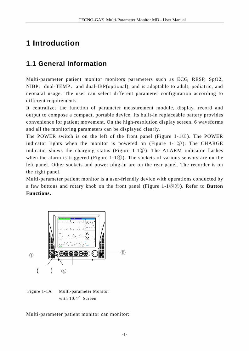
Multi-parameter patient monitor monitors parameters such as ECG, RESP, SpO2, NIBP,dual-TEMP,and dual-IBP(optional), and is adaptable to adult, pediatric, and neonatal usage. The user can select different parameter configuration according to different requirements. It centralizes the function of parameter measurement module, display, record and output to compose a compact, portable device. Its built-in replaceable battery provides convenience for patient movement. On the high-resolution display screen, 6 waveforms and all the monitoring parameters can be displayed clearly. The POWER switch is on the left of the front panel (Figure 1-1① ). The POWER indicator lights when the monitor is powered on (Figure 1-1② ). The CHARGE indicator shows the charging status (Figure 1-1③ ). The ALARM indicator flashes when the alarm is triggered (Figure 1-1④ ). The sockets of various sensors are on the left panel. Other sockets and power plug-in are on the rear panel. The recorder is on the right panel. Multi-parameter patient monitor is a user-friendly device with operations conducted by a few buttons and rotary knob on the front panel (Figure 1-1⑤⑥ ). Refer to Button Functions.
Multi-parameter patient monitor can monitor:
(ÇÉ) ④ Ö
⑥ ①
Figure 1-1A Multi-parameter Monitor with 10.4〞Screen
④

TECNO-GAZ Multi-Parameter Monitor MD - User Manual
-2-
ECG: Heart Rate (HR) 2-channel ECG waveform Arrhythmia and ST-segment analysis (optional)
RESP: Respiration Rate (RR) Respiration Waveform
SpO2: Oxygen Saturation (SpO2), Pulse Rate (PR) SpO2 Plethysmogram
NIBP: Systolic Pressure (NS), Diastolic Pressure (ND), Mean Pressure (NM)
TEMP: Channel-1 Temperature (T1), Channel-2 Temperature (T2), Temperature Difference between two channels (TD)
IBP: Channel-1 SYS, DIA, MAP Channel-2 SYS, DIA, MAP Dual-IBP waveforms
The patient monitor provides extensive functions as visual & audible alarm, storage for trend data, NIBP measurements, alarm events, and drug dose calculation.
1.2 Screen Display
Multi-parameter patient monitor is equipped with a high-resolution multicolor TFT LCD screen. The patient parameters, waveforms, alarm messages, bed number, time, monitor status and other data can be reflected from the screen. The screen is divided into three areas: 1 Information Area; 2 Waveform Area; 3 Parameter Area.
Figure 1-2 Main Interface
①
④
②
③
TECNO-GAZ Multi-Parameter Monitor MD - User Manuall
-3-
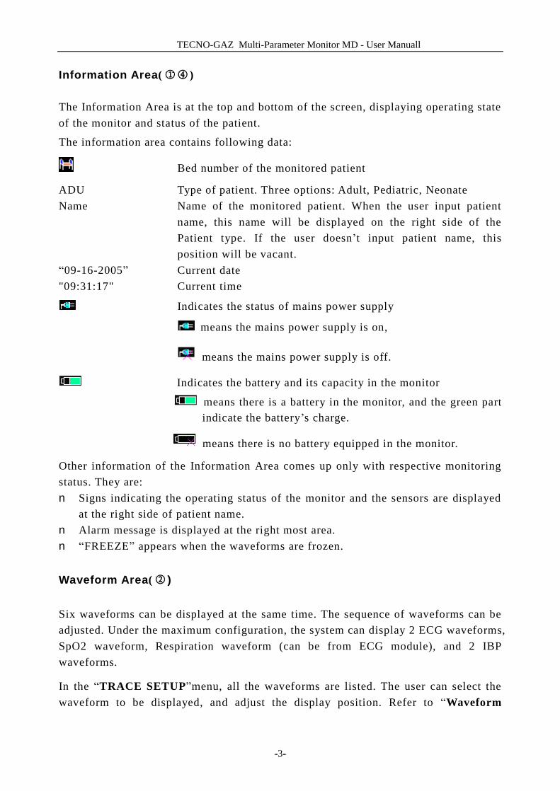
Information Area(①④) The Information Area is at the top and bottom of the screen, displaying operating state of the monitor and status of the patient.
The information area contains following data:
Bed number of the monitored patient
ADU Type of patient. Three options: Adult, Pediatric, Neonate Name Name of the monitored patient. When the user input patient
name, this name will be displayed on the right side of the Patient type. If the user doesn’t input patient name, this position will be vacant.
“09-16-2005” Current date "09:31:17" Current time
Indicates the status of mains power supply
means the mains power supply is on,
means the mains power supply is off.
Indicates the battery and its capacity in the monitor
means there is a battery in the monitor, and the green part indicate the battery’s charge.
means there is no battery equipped in the monitor.
Other information of the Information Area comes up only with respective monitoring status. They are: n Signs indicating the operating status of the monitor and the sensors are displayed
at the right side of patient name. n Alarm message is displayed at the right most area. n “FREEZE” appears when the waveforms are frozen.
Waveform Area(② )
Six waveforms can be displayed at the same time. The sequence of waveforms can be adjusted. Under the maximum configuration, the system can display 2 ECG waveforms, SpO2 waveform, Respiration waveform (can be from ECG module), and 2 IBP waveforms.
In the “TRACE SETUP”menu, all the waveforms are listed. The user can select the waveform to be displayed, and adjust the display position. Refer to “Waveform
TECNO-GAZ Multi-Parameter Monitor MD - User Manual
-4-
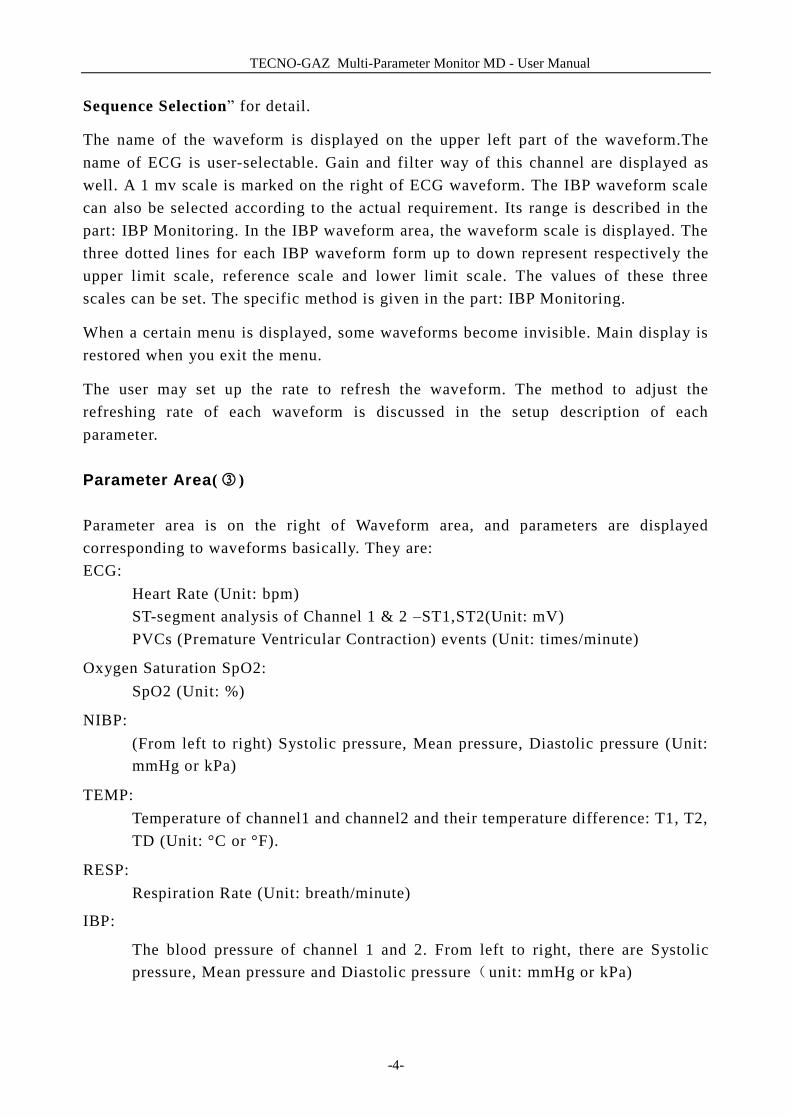
Sequence Selection” for detail.
The name of the waveform is displayed on the upper left part of the waveform.The name of ECG is user-selectable. Gain and filter way of this channel are displayed as well. A 1 mv scale is marked on the right of ECG waveform. The IBP waveform scale can also be selected according to the actual requirement. Its range is described in the part: IBP Monitoring. In the IBP waveform area, the waveform scale is displayed. The three dotted lines for each IBP waveform form up to down represent respectively the upper limit scale, reference scale and lower limit scale. The values of these three scales can be set. The specific method is given in the part: IBP Monitoring.
When a certain menu is displayed, some waveforms become invisible. Main display is restored when you exit the menu.
The user may set up the rate to refresh the waveform. The method to adjust the refreshing rate of each waveform is discussed in the setup description of each parameter. Parameter Area(③) Parameter area is on the right of Waveform area, and parameters are displayed corresponding to waveforms basically. They are: ECG:
Heart Rate (Unit: bpm) ST-segment analysis of Channel 1 & 2 –ST1,ST2(Unit: mV) PVCs (Premature Ventricular Contraction) events (Unit: times/minute)
Oxygen Saturation SpO2: SpO2 (Unit: %)
NIBP: (From left to right) Systolic pressure, Mean pressure, Diastolic pressure (Unit:
mmHg or kPa)
TEMP: Temperature of channel1 and channel2 and their temperature difference: T1, T2,
TD (Unit: °C or °F).
RESP: Respiration Rate (Unit: breath/minute)
IBP:
The blood pressure of channel 1 and 2. From left to right, there are Systolic pressure, Mean pressure and Diastolic pressure(unit: mmHg or kPa)
TECNO-GAZ Multi-Parameter Monitor MD - User Manual
-5-
Alarm Indicator and Alarm Status Under normal status, the alarm indicator won’t light. When alarming, the alarm indicator lights or flashes. The color of light represents the alarm level. Refer to “Alarm Functions” for detail. Refer to relative content of parameter for Alarm information and prompt.
Charge Indicator and Charge Status (take for monitor with 10.4〞screen example)
To indicate the status of switching on or charging. When the monitor is switched on,
the indictor will flash with green light. And then if the battery is charged, the light
color will turn to orange.
1.3 Button Functions
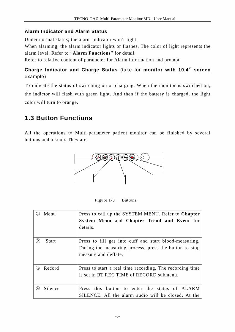
All the operations to Multi-parameter patient monitor can be finished by several buttons and a knob. They are:
Figure 1-3 Buttons
① Menu Press to call up the SYSTEM MENU. Refer to Chapter System Menu and Chapter Trend and Event for details.
S② tart Press to fill gas into cuff and start blood-measuring. During the measuring process, press the button to stop measure and deflate.
③ Record Press to start a real time recording. The recording time is set in RT REC TIME of RECORD submenu.
④ Silence Press this button to enter the status of ALARM SILENCE. All the alarm audio will be closed. At the
Ü
Ö Ñ
á
Å Ç
É
TECNO-GAZ Multi-Parameter Monitor MD - User Manual
-6-
same time, “Alarm Pause xx s” will be displayed in the parameter alarm area. When repress it or the pause time is over, the system will stop pausing, and resume to the normal monitoring status, and “Alarm Pause xx s” will vanish. NOTE: Whether an alarm will be reset depends on the status of the alarm cause. But by pressing SILENCE button (suspend alarm) can permanently shut off audio sound of the Lead Off or Sensor Off alarms. So the user can exit the Alarm Silence Status by Technical Alarm.
⑤ Freeze When in normal mode, press this button to freeze all the waveforms on the screen. When in FREEZE mode, press to restore the waveform refreshing.
⑥ Main Press to return to the main interface.
⑦ Rotary Knob The user may use the rotary knob to select the menu item and modify the setup. It can be rotated clockwise or anticlockwise and pressed like other buttons. The user may use the knob to realize the operations on the screen and in the system menu and parameter menu.
Method to Use the Knob to Operate on the Screen:
The rectangular mark on the screen that moves with the rotation of the knob is called
“cursor”. Operation can be performed at any position at which the cursor can stay.
When the cursor is in the waveform area, the user may immediately modify the current
setup. When the cursor is in the parameter area, the user may open the setup menu of
the corresponding parameter module so as to set up the menu items of the module.
Operating method:
■ Move the cursor to the item where the operation is wanted
■ Press the knob
■ One of the following four situations may appear:
TECNO-GAZ Multi-Parameter Monitor MD - User Manual
-7-
1. The cursor with background color may become into the frame without background color, which implies that the content in the frame can change with the rotation of the knob.
2. Menu or measuring window may appear on the screen, or the original menu is replaced by the new menu.
3. A check mark “√” appears at the position, indicating that the item is confirmed.
4. The system immediately executes a certain function.
1.4 Interfaces
For the convenience of operator, interfaces of different function are in different sites of the monitor.
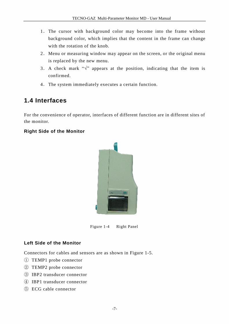
Right Side of the Monitor
Figure 1-4 Right Panel
Left Side of the Monitor
Connectors for cables and sensors are as shown in Figure 1-5. ① TEMP1 probe connector ② TEMP2 probe connector ③ IBP2 transducer connector ④ IBP1 transducer connector ⑤ ECG cable connector

TECNO-GAZ Multi-Parameter Monitor MD - User Manual
-8-
⑥ NIBP cuff connector ⑦ SpO2 sensor connector
Figure1-5 Left Panel
This symbol means “BE CAREFUL". Refer to the manual.
Indicates that the instrument is IEC60601-1 Type CF equipment. The unit displ-
aying this symbol contains an F-Type isolated (floating) patient applied part providing a high degree of protection against shock, and is suitable for use during defibrillation.
Rear Panel
Figure 1-6 Rear Panel
Sockets on the rear panel are shown in Figure 1-6.
①
②
③④
⑤
⑥ ⑦
T2
T1
SpO2
IBP2
NIBP
ECG
IBP1
CO
CO2
④
① ③
②
!

TECNO-GAZ Multi-Parameter Monitor MD - User Manual
-9-
① Network Interface: Standard RJ45 Socket. (reserved) ② Equipotential grounding terminal for connection with the hospital’s grounding
system. ③ Fuse box, used to put fuse in. ④ Power supply socket: AC100-240 V, 50/60 Hz
1.5 Label
Figure1-7 Label on the Rear Panel
Figure1-8 Label on the Package
1.6 Built-in Chargeable Battery
Multi-parameter Patient Monitor is equipped with a built-in chargeable battery. When switch on AC power supply, the battery will be charged automatically until full electric energy. There is a sign “ ” in the lower left corner of screen to show the
Model & Serial No.
Manufacturer Information
Equipment name
Manufacturing Date
Product Information
Manufacturer Address
TECNO-GAZ Multi-Parameter Monitor MD - User Manual
-10-
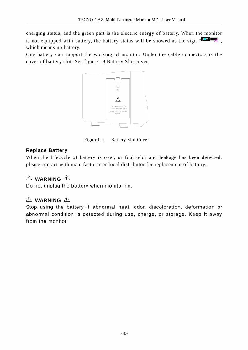
charging status, and the green part is the electric energy of battery. When the monitor is not equipped with battery, the battery status will be showed as the sign “ ”, which means no battery. One battery can support the working of monitor. Under the cable connectors is the cover of battery slot. See figure1-9 Battery Slot cover.
Figure1-9 Battery Slot Cover
Replace Battery When the lifecycle of battery is over, or foul odor and leakage has been detected, please contact with manufacturer or local distributor for replacement of battery.
WARNING Do not unplug the battery when monitoring.
WARNING Stop using the battery if abnormal heat, odor, discoloration, deformation or abnormal condition is detected during use, charge, or storage. Keep it away from the monitor.
TECNO-GAZ Multi-Parameter Monitor MD - User Manual
-11-
2 Installation of Monitor
■ Open the package and check ■ Install wall mount for patient monitor ■ Connect the power cables ■ Power on the monitor ■ Connect patient sensors ■ Check the recorder
NOTE: To ensure that the monitor works properly, please read Chapter Safety Guidance, and follow the steps before using the monitor.
2.1 Open the Package and Check
Open the package and take out the monitor and accessories carefully. Keep the package for possible future transportation or storage. Check the components according to the packing list. n Check for any mechanical damage. n Check all the cables, modules and accessories. If there is any problem, contact the distributor immediately.
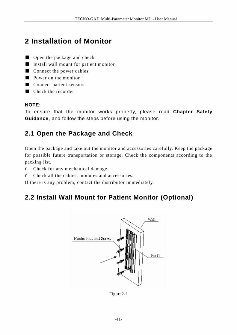
2.2 Install Wall Mount for Patient Monitor (Optional)
Figure2-1
TECNO-GAZ Multi-Parameter Monitor MD - User Manual
-12-
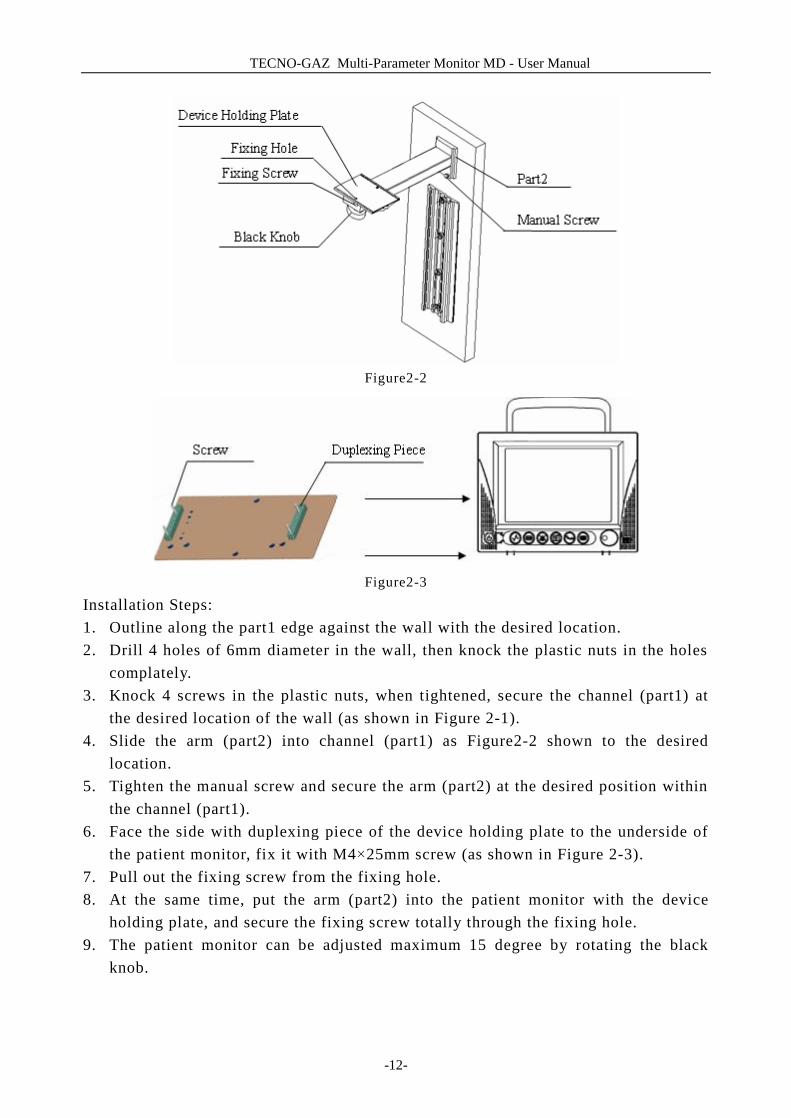
Figure2-2
Figure2-3
Installation Steps: 1. Outline along the part1 edge against the wall with the desired location. 2. Drill 4 holes of 6mm diameter in the wall, then knock the plastic nuts in the holes
complately. 3. Knock 4 screws in the plastic nuts, when tightened, secure the channel (part1) at
the desired location of the wall (as shown in Figure 2-1). 4. Slide the arm (part2) into channel (part1) as Figure2-2 shown to the desired
location. 5. Tighten the manual screw and secure the arm (part2) at the desired position within
the channel (part1). 6. Face the side with duplexing piece of the device holding plate to the underside of
the patient monitor, fix it with M4×25mm screw (as shown in Figure 2-3). 7. Pull out the fixing screw from the fixing hole. 8. At the same time, put the arm (part2) into the patient monitor with the device
holding plate, and secure the fixing screw totally through the fixing hole. 9. The patient monitor can be adjusted maximum 15 degree by rotating the black
knob.
TECNO-GAZ Multi-Parameter Monitor MD - User Manual
-13-
2.3 Connect the Power Cables
Connection procedure of the AC power line: n Make sure the AC power supply complies with following specification: 100~240
VAC, 50/60 Hz. n Apply the power line provided with the monitor. Plug the power line to INPUT
interface of the monitor (Socket ④ in Figure 1-6). Connect the other end of the power line to a grounded 3-phase power output.
NOTE: Connect the power line to the jack special for hospital usage. n Connect to the ground line if necessary. Refer to Chapter Safety Guidance for
details. NOTE: When the battery configuration is provided, after the device is transported or stored, the battery must be charged. Powering on without connecting AC power supply may cause the device out of work. Switch on AC power supply can charge the battery no matter if the monitor is powered on.
2.4 Power on the Monitor
Power on, LOGO information will be displayed on the screen. NOTE: Check all the functions that may be used to monitor and make sure that the monitor is in good status.
NOTE: If chargeable batteries are provided, charge them after using the device every time to ensure the electric power is enough.
WARNING If any sign of damage is detected, or the monitor displays some error messages, do not use it on any patient. Contact biomedical engineer in the hospital or Customer Service Center immediately. NOTE: The interval between twice press of POWER should be more than 1 minute.
TECNO-GAZ Multi-Parameter Monitor MD - User Manual
-14-
NOTE: After continious 360-hour runtime, please restart the monitor to ensure the monitor ’s steady performance and long lifespan.
2.5 Connect Patient Sensors
Connect all the necessary patient sensors between the monitor and the patient.
NOTE: For information on correct connection, refer to related chapters.
2.6 Check the Recorder
If your monitor is equipped with a recorder, open the recorder door to check if paper is properly installed in the slot. If no paper present, refer to Chapter Recording for details.
TECNO-GAZ Multi-Parameter Monitor MD - User Manual
-15-
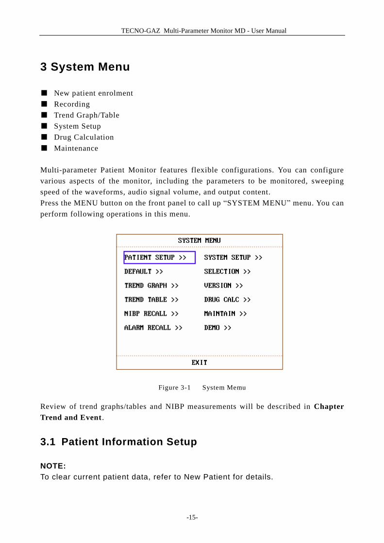
3 System Menu
■ New patient enrolment ■ Recording ■ Trend Graph/Table ■ System Setup ■ Drug Calculation ■ Maintenance
Multi-parameter Patient Monitor features flexible configurations. You can configure various aspects of the monitor, including the parameters to be monitored, sweeping speed of the waveforms, audio signal volume, and output content. Press the MENU button on the front panel to call up “SYSTEM MENU” menu. You can perform following operations in this menu.
Figure 3-1 System Memu
Review of trend graphs/tables and NIBP measurements will be described in Chapter Trend and Event .
3.1 Patient Information Setup
NOTE: To clear current patient data, refer to New Patient for details.
TECNO-GAZ Multi-Parameter Monitor MD - User Manual
-16-
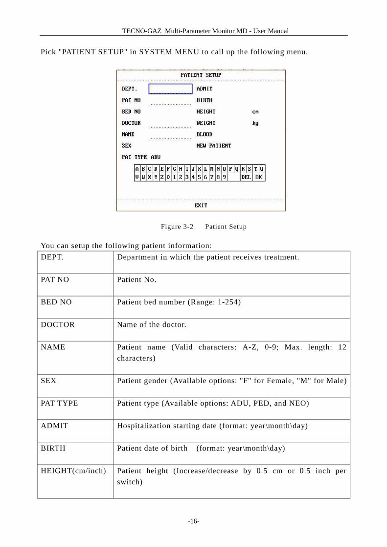
Pick "PATIENT SETUP" in SYSTEM MENU to call up the following menu.
Figure 3-2 Patient Setup
You can setup the following patient information: DEPT. Department in which the patient receives treatment.
PAT NO Patient No.
BED NO Patient bed number (Range: 1-254)
DOCTOR Name of the doctor.
NAME Patient name (Valid characters: A-Z, 0-9; Max. length: 12
characters)
SEX Patient gender (Available options: "F" for Female, "M" for Male)
PAT TYPE Patient type (Available options: ADU, PED, and NEO)
ADMIT Hospitalization starting date (format: year\month\day)
BIRTH Patient date of birth (format: year\month\day)
HEIGHT(cm/inch) Patient height (Increase/decrease by 0.5 cm or 0.5 inch per switch)
TECNO-GAZ Multi-Parameter Monitor MD - User Manuall
-17-
WEIGHT(kg/lb) Patient weight (Increase/decrease by 0.5 kg or 0.5 lb per switch)
BLOOD Patient blood type (Pick A, B, O, AB, or N. "N" represents unknown blood type)
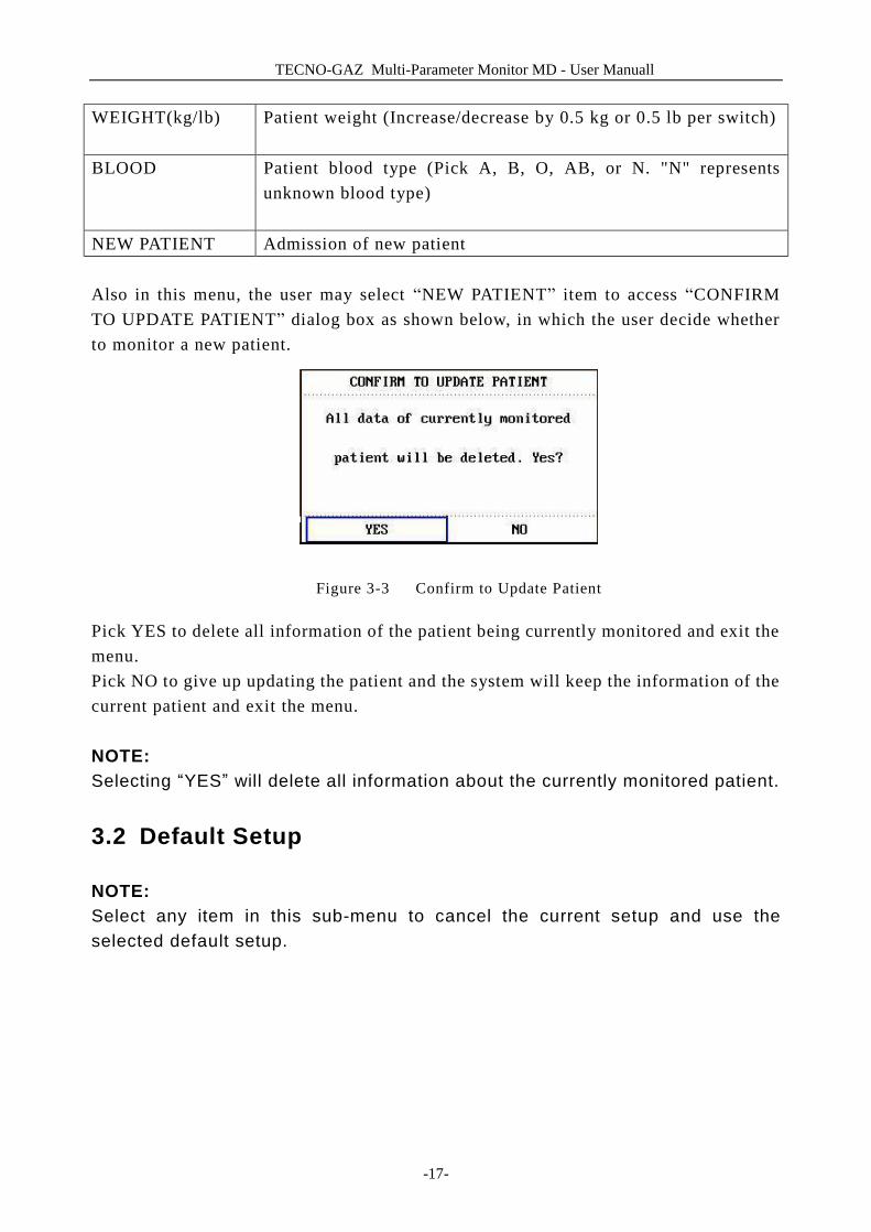
NEW PATIENT Admission of new patient Also in this menu, the user may select “NEW PATIENT” item to access “CONFIRM TO UPDATE PATIENT” dialog box as shown below, in which the user decide whether to monitor a new patient.
Figure 3-3 Confirm to Update Patient
Pick YES to delete all information of the patient being currently monitored and exit the menu. Pick NO to give up updating the patient and the system will keep the information of the current patient and exit the menu.
NOTE: Selecting “YES” will delete all information about the currently monitored patient.
3.2 Default Setup
NOTE: Select any item in this sub-menu to cancel the current setup and use the selected default setup.
TECNO-GAZ Multi-Parameter Monitor MD - User Manual
-18-
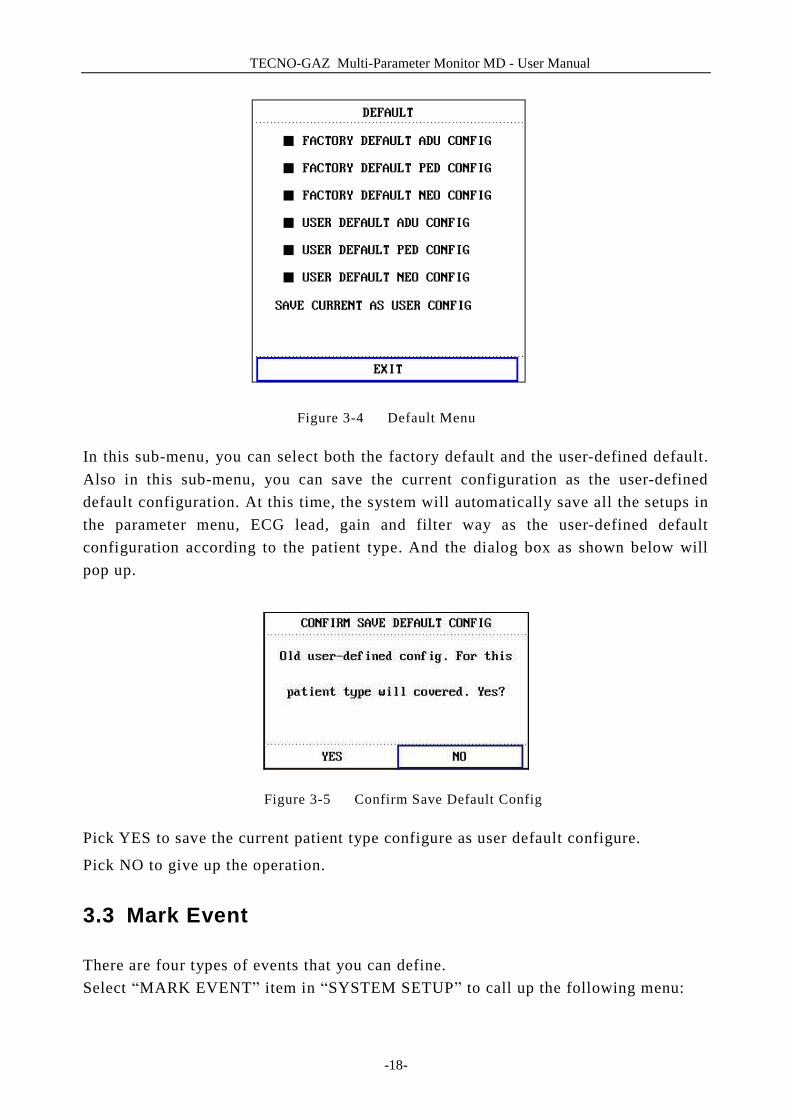
Figure 3-4 Default Menu
In this sub-menu, you can select both the factory default and the user-defined default. Also in this sub-menu, you can save the current configuration as the user-defined default configuration. At this time, the system will automatically save all the setups in the parameter menu, ECG lead, gain and filter way as the user-defined default configuration according to the patient type. And the dialog box as shown below will pop up.
Figure 3-5 Confirm Save Default Config
Pick YES to save the current patient type configure as user default configure.
Pick NO to give up the operation.
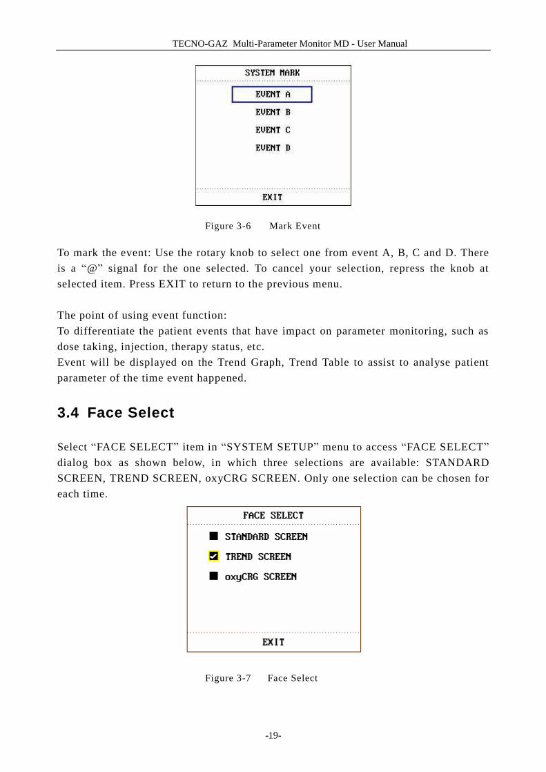
3.3 Mark Event
There are four types of events that you can define. Select “MARK EVENT” item in “SYSTEM SETUP” to call up the following menu:
TECNO-GAZ Multi-Parameter Monitor MD - User Manual
-19-
Figure 3-6 Mark Event
To mark the event: Use the rotary knob to select one from event A, B, C and D. There is a “@” signal for the one selected. To cancel your selection, repress the knob at selected item. Press EXIT to return to the previous menu. The point of using event function: To differentiate the patient events that have impact on parameter monitoring, such as dose taking, injection, therapy status, etc. Event will be displayed on the Trend Graph, Trend Table to assist to analyse patient parameter of the time event happened.
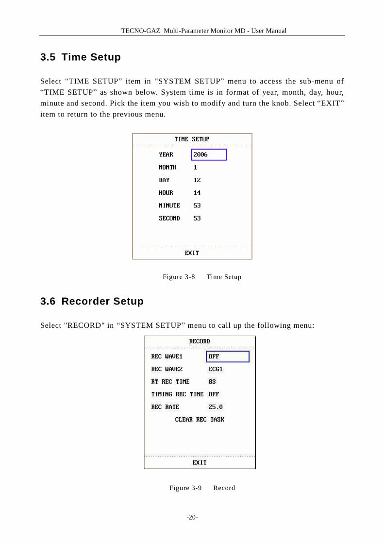
3.4 Face Select
Select “FACE SELECT” item in “SYSTEM SETUP” menu to access “FACE SELECT” dialog box as shown below, in which three selections are available: STANDARD SCREEN, TREND SCREEN, oxyCRG SCREEN. Only one selection can be chosen for each time.
Figure 3-7 Face Select
TECNO-GAZ Multi-Parameter Monitor MD - User Manual
-20-
3.5 Time Setup
Select “TIME SETUP” item in “SYSTEM SETUP” menu to access the sub-menu of “TIME SETUP” as shown below. System time is in format of year, month, day, hour, minute and second. Pick the item you wish to modify and turn the knob. Select “EXIT” item to return to the previous menu.
Figure 3-8 Time Setup
3.6 Recorder Setup
Select "RECORD" in “SYSTEM SETUP” menu to call up the following menu:
Figure 3-9 Record

TECNO-GAZ Multi-Parameter Monitor MD - User Manual
-21-
In the sub-menu, the user may select the waveforms to be output in “REC WAVE1” and “REC WAVE2” items.
ECG1, ECG2 ECG1 waveform and ECG2 waveform. (There will be 7
ECG waveforms on the screen when Full-Lead display).
If no ECG waveform is currently displayed on the screen,
this item cannot be picked.
SPO2 SpO2 Plethysmogram. (If no SpO2 waveform is currently
displayed on the screen, this item cannot be picked. But
under ECG Full-Lead display mode, this item can be
picked, although no SpO2 waveform is currently
displayed on the screen. )
RESP RESP waveform. (If no RESP waveform is currently
displayed on the screen, this item cannot be picked. But
under ECG Full-Lead display mode, this item can be
picked, although no RESP waveform is currently
displayed on the screen.)
IBP1, IBP2 IBP1 waveform and IBP2 waveform. (If no IBP waveform
is currently displayed on the screen, this item cannot be
picked. But under ECG Full-Lead display mode, this item
can be picked, although no IBP waveform is currently
displayed on the screen.))
OFF No display for this waveform.
l RT REC TIME represents “real-time recording time”, for which two selections are
available: CONTINUAL and 8S. “CONTINUAL” means once pressing button on the front panel, the recorder will continuously print out the waveform or
parameter until button is pressed again.
TECNO-GAZ Multi-Parameter Monitor MD - User Manual
-22-
l TIMING REC TIME represents “time interval between two times of timing recording”. 10 selections are available: “OFF, 10MIN, 20MIN, 30MIN, 40MIN, 50MIN, 1HOUR, 2HOURS, 3HOURS and 4HOURS”. It means that the system will trigger the recording operation according to the selected time interval. The recording time is fixed at 8 seconds.
NOTE: REC TIME has the priority compared with TIMING REC TIME.
l REC RATE: 25.0 mm/s or 50.0 mm/s.. l CLEAR REC TASK can be used by the user to stop recorder from printing out too
many tasks.
NOTE: The recorder is an optional part. NOTE: If two same waveforms are selected, one of them is switched to a different waveform automatically.
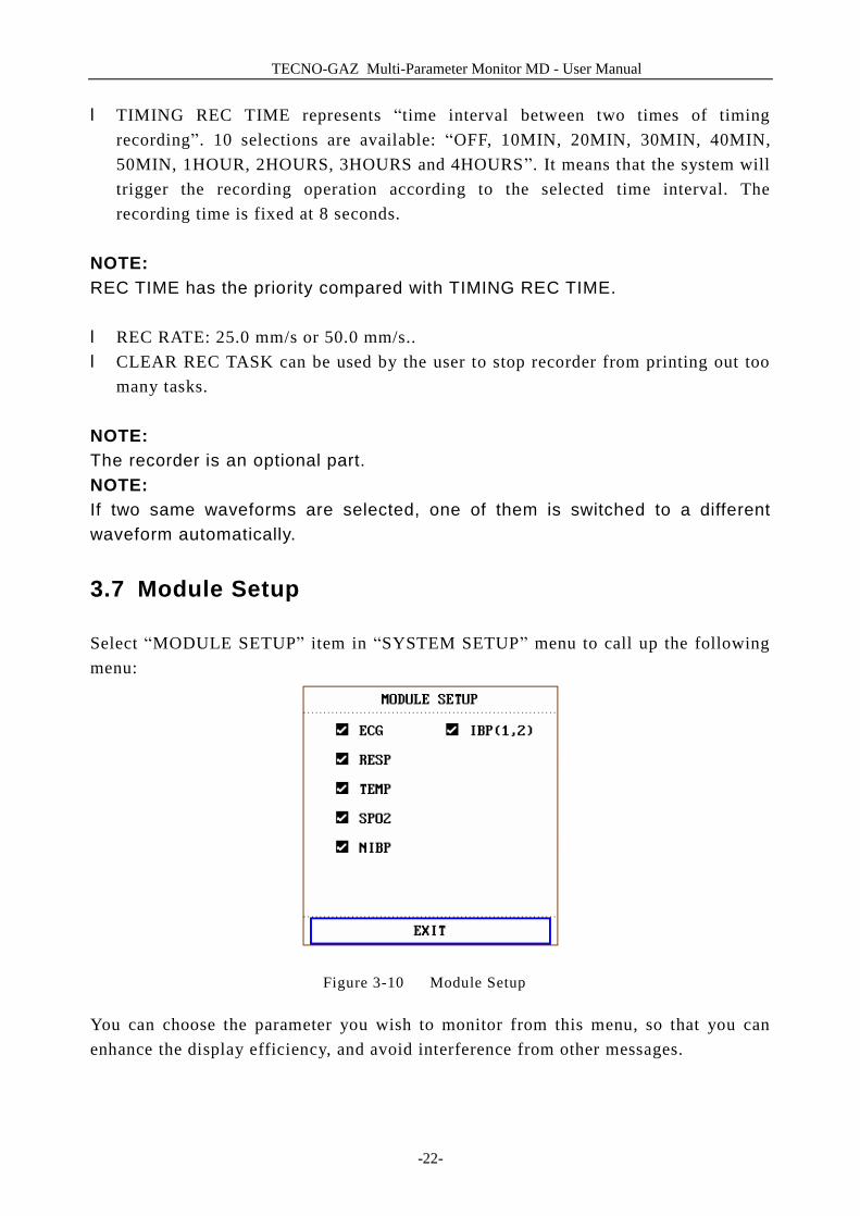
3.7 Module Setup
Select “MODULE SETUP” item in “SYSTEM SETUP” menu to call up the following menu:
Figure 3-10 Module Setup
You can choose the parameter you wish to monitor from this menu, so that you can enhance the display efficiency, and avoid interference from other messages.

TECNO-GAZ Multi-Parameter Monitor MD - User Manual
-23-
3.8 Tracing Waveforms Selection
Select “TRACE SETUP” item in “SYSTEM SETUP” menu to call up the following menu:
Figure 3-11 Trace Setup
You can define the traces displayed on the screen in this menu. The waveforms available for selection are those whose modules have been selected in “MODULE SETUP” menu.
3.9 Monitor Version
Pick VERSION to show the software version information of this monitor.
3.10 Alarm Volume
The system provides five levels of alarm volume and an alarm silence function. The system will give audio alarm prompt (including no alarm sound) based on the selection.
The user may select different level of volume as per clinical requirement. The method is listed below: Press “ALARM SETUP” item in “SYSTEM SETUP” menu to call up “ALARM SETUP” sub-menu as shown below, in which the user may set up the alarm volume and other alarm information. Refer to Chapter Alarm for detailed information.
TECNO-GAZ Multi-Parameter Monitor MD - User Manual
-24-
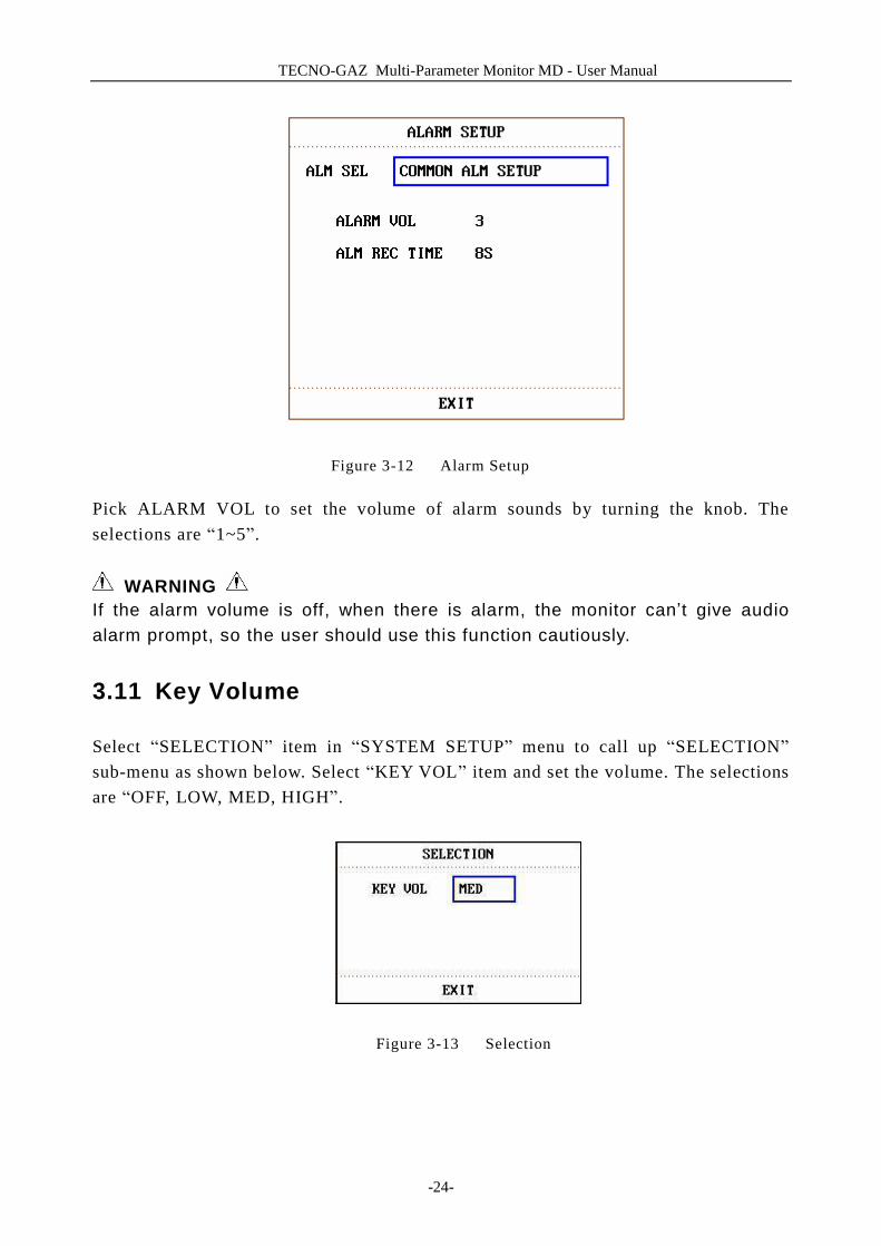
Figure 3-12 Alarm Setup
Pick ALARM VOL to set the volume of alarm sounds by turning the knob. The selections are “1~5”.
WARNING If the alarm volume is off, when there is alarm, the monitor can’t give audio alarm prompt, so the user should use this function cautiously.
3.11 Key Volume
Select “SELECTION” item in “SYSTEM SETUP” menu to call up “SELECTION” sub-menu as shown below. Select “KEY VOL” item and set the volume. The selections are “OFF, LOW, MED, HIGH”.
Figure 3-13 Selection
TECNO-GAZ Multi-Parameter Monitor MD - User Manual
-25-
3.12 Drug Calculation
The patient monitor provide drug calculation and titration table display functions for fifteen different drugs. For details, please refer to the Chapter: Drug Calculation and Titration Table.
3.13 Waveform Demonstration
Select “DEMO” item in “SYSTEM MENU” to call up “INPUT DEMO KEY”. After entering the password, the system enters the Demonstration Waveform status.
The purpose of waveform demonstration is only to demonstrate the machine performance, and for training purpose. In clinical application, this function is not recommended because the DEMO will mislead the hospital workers to treat the waveform and parameter as actual data of the patient, which may result in delay of treatment or mistreatment.
3.14 Maintenance
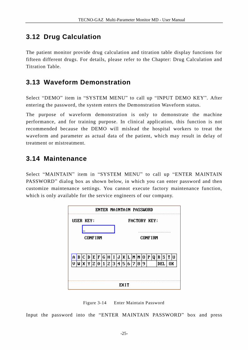
Select “MAINTAIN” item in “SYSTEM MENU” to call up “ENTER MAINTAIN PASSWORD” dialog box as shown below, in which you can enter password and then customize maintenance settings. You cannot execute factory maintenance function, which is only available for the service engineers of our company.
Figure 3-14 Enter Maintain Password
Input the password into the “ENTER MAINTAIN PASSWORD” box and press
TECNO-GAZ Multi-Parameter Monitor MD - User Manual
-26-
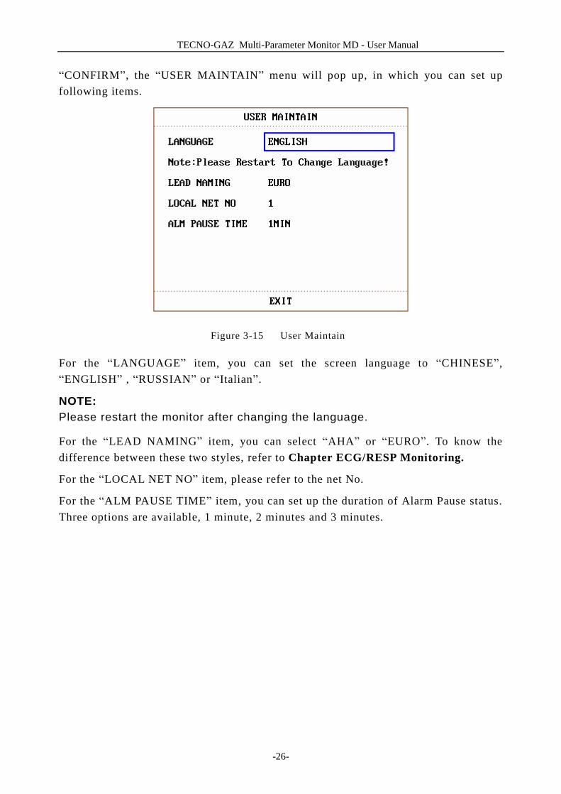
“CONFIRM”, the “USER MAINTAIN” menu will pop up, in which you can set up following items.
Figure 3-15 User Maintain
For the “LANGUAGE” item, you can set the screen language to “CHINESE”, “ENGLISH” , “RUSSIAN” or “Italian”.
NOTE: Please restart the monitor after changing the language.
For the “LEAD NAMING” item, you can select “AHA” or “EURO”. To know the difference between these two styles, refer to Chapter ECG/RESP Monitoring.
For the “LOCAL NET NO” item, please refer to the net No.
For the “ALM PAUSE TIME” item, you can set up the duration of Alarm Pause status. Three options are available, 1 minute, 2 minutes and 3 minutes.
TECNO-GAZ Multi-Parameter Monitor MD - User Manual
-27-
4 Face Select
This monitor has three different operating screens, which are “Standard Screen”, “Trend Screen”, “oxyCRG Screen”. When required, you can select different operating screens for necessary information. Let’s probe into these three operating screens one by one.
4.1 Select Operating Screen
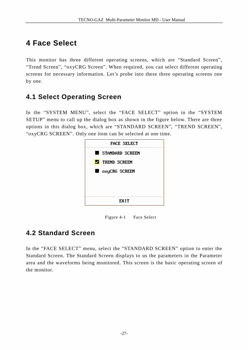
In the “SYSTEM MENU”, select the “FACE SELECT” option in the “SYSTEM SETUP” menu to call up the dialog box as shown in the figure below. There are three options in this dialog box, which are “STANDARD SCREEN”, “TREND SCREEN”, “oxyCRG SCREEN”. Only one item can be selected at one time.
Figure 4-1 Face Select
4.2 Standard Screen
In the “FACE SELECT” menu, select the “STANDARD SCREEN” option to enter the Standard Screen. The Standard Screen displays to us the parameters in the Parameter area and the waveforms being monitored. This screen is the basic operating screen of the monitor.

TECNO-GAZ Multi-Parameter Monitor MD - User Manual
-28-
Figure 4-2 Standard Screen
4.3 Trend Screen
n Enter TREND SCREEN In the “FACE SELECT” menu, select the“TREND SCREEN”option to enter the Trend Screen.
Figure 4-3 Trend Screen
TECNO-GAZ Multi-Parameter Monitor MD - User Manual
-29-
n Position of trend graph Trend graph is located to the right of the corresponding waveform in the Waveform area. Its color is the same as that of the corresponding parameter. n Trend length Dynamic trend length is 2 hours. On the trend graph, the scale of the right end of the X-axis is 0 hour while the left end is 2-hour. n Select trend parameter If multiple parameters are located at the same position on the trend graph, by selecting the corresponding hot key of a parameter on the trend graph, you can have the trend graph of this parameter displayed on the screen. For example, in ECG trend graph, you can select hot keys such as HR, ST or PVCs, then the system will display their corresponding trend graphs respectively. n Close trend screen In the “FACE SELECT” menu, select options of other operating screens to close the Trend Screen.
4.4 oxyCRG Screen
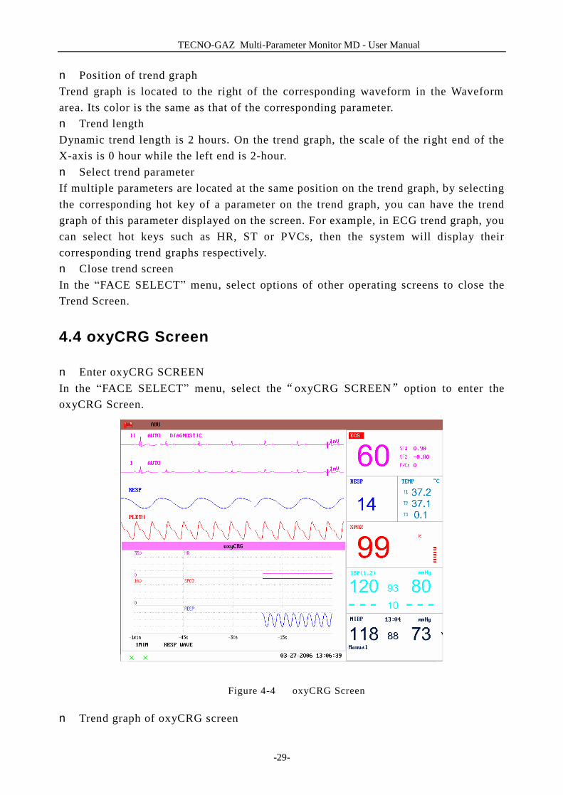
n Enter oxyCRG SCREEN In the “FACE SELECT” menu, select the“oxyCRG SCREEN”option to enter the oxyCRG Screen.
Figure 4-4 oxyCRG Screen
n Trend graph of oxyCRG screen
TECNO-GAZ Multi-Parameter Monitor MD - User Manual
-30-
Located at the lower part of the screen, oxyCRG screen consists of three trends: HR Trend, SpO2 Trend and RR Trend or Compressed Resp. Waveform. n Select oxyCRG trend length Three are two hot keys at the bottom part of the oxyCRG Screen, which are 4MIN/2MIN/1MIN, RR/RESP WAVE. By using hot keys for trend time, you may select to display trend graphs of three different lengths, i.e., 1 min, 2 min and 4 min. n Select RR trend or Compressed Resp. Waveform By using the hot keys for RR/RESP WAVE, you may select either RR trend graph or compressed Resp. Wave. They occupy the same position. Therefore, if select “RR”, the position displays the dynamic trend of RR. If select “RESP WAVE”, the position displays the compressed Resp. Wave. n Close oxyCRG In the FACE SELECT menu, select options of other operating screens to close the oxyCRG Screen.
TECNO-GAZ Multi-Parameter Monitor MD - User Manual
-31-
5 Alarm
This chapter gives general information about the alarm and measures to be taken accordingly. Alarm setup and prompt messages are provided in respective parameter setup sections.
5.1 Alarm Modes
5.1.1 Alarm Level
Each alarm, either technical or physiological, has its own level. For alarm of higher level, when it occurs, the system will give prompt in various ways. Some alarm’s level can be set by the user via software. Others can not be changed once defined by the system. Alarms in Multi-parameter patient monitor are divided into three levels, that is, high, medium and low.
High-level alarm indicates the patient’s life is in danger or the monitor under using has serious problem in technical respect. It is the most serious alarm. Medium-level alarm means serious warning. Low-level alarm is a general warning.
Alarms are classified into three categories, which are physiological alarm, technical alarm and general alarm. Physiological alarm refer to those alarms triggered by patient’s physiological situation which could be considered dangerous to his or her life, such as heart rate (HR) exceeding alarm limit (parameter alarms). Technical alarm refer to system failure which can make certain monitoring process technically impossible or make monitoring result unbelievable. Technical alarm is also called System Error Message. General alarm belongs to those situations that can not be categorized into these two cases but still need to pay some attention.
Multi-parameter patient monitor has preset the alarm level for the parameters. You can also modify the alarm level using the method described in this chapter.
Alarm level of the System Error Message (technical alarm) is pre-set in the system. All technical alarm level and general alarm level, some of the physiological alarm level are pre-set in the system and can not be changed by user.
TECNO-GAZ Multi-Parameter Monitor MD - User Manual
-32-
5.1.2 Alarm Modes
When alarm occurs, Multi-parameter patient monitor may raise the user ’s attention in at least three ways, which are audio prompt, visual prompt and description. Audio and visual prompt is given by TFT display device, the speaker on the display device and the alarm indicator. Description is displayed on the screen. Physiological alarm is displayed in the Physiological Alarm area. Most of technical alarms are displayed in the Technical Alarm area. Technical alarms related to NIBP measurement are displayed in the NIBP Technical Alarm area at the bottom of NIBP parameter area.
NOTE: The Physiological Alarm area is on the upper right part of the screen. The Technical Alarm area is to the left side of the Physiological Alarm area.
NOTE: If Multi-parameter patient monitor is connected to the external alarm prompt system (e.g. the alarm speaker and indicator connected onto the rear panel of the monitor), when alarm occurs, the external alarm prompt system responds in the same way as the the monitor.
NOTE: The concrete presentation of each alarm prompt is related to the alarm level.
How to indicate that the measured parameter has exceeded its alarm limits:
When physiological alarm of the monitored parameter exceeds the alarm limit, besides using the above-mentioned three ways to give the alarm prompt, the monitor also gives alarm by making the monitored parameter flash in the frequency of 1Hz.
Screen Display
When the measured parameter exceeds its alarm limits and triggers a physiological alarm, the corresponding parameter value will flash. “*” signal appears on the screen indicating the occurrence of alarm. Red “***” indicates high-level alarm, yellow “**” indicates medium-level alarm, and yellow “*” indicates low-level alarm. Technical alarm will not prompts “*” signal.
Lamp light
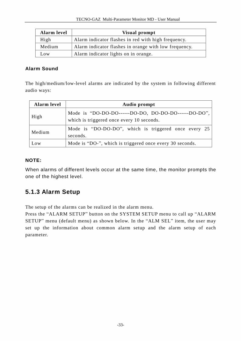
The high/medium/low-level alarms are indicated by the system in following different visual ways:
TECNO-GAZ Multi-Parameter Monitor MD - User Manual
-33-
Alarm level Visual prompt High Alarm indicator flashes in red with high frequency. Medium Alarm indicator flashes in orange with low frequency. Low Alarm indicator lights on in orange.
Alarm Sound
The high/medium/low-level alarms are indicated by the system in following different audio ways:
Alarm level Audio prompt
High Mode is “DO-DO-DO------DO-DO, DO-DO-DO------DO-DO”, which is triggered once every 10 seconds.
Medium Mode is “DO-DO-DO”, which is triggered once every 25 seconds.
Low Mode is “DO-”, which is triggered once every 30 seconds.
NOTE:
When alarms of different levels occur at the same time, the monitor prompts the one of the highest level.
5.1.3 Alarm Setup
The setup of the alarms can be realized in the alarm menu. Press the “ALARM SETUP” button on the SYSTEM SETUP menu to call up “ALARM SETUP” menu (default menu) as shown below. In the “ALM SEL” item, the user may set up the information about common alarm setup and the alarm setup of each parameter.

TECNO-GAZ Multi-Parameter Monitor MD - User Manual
-34-
Figure 5-1 Alarm Setup
n COMMON ALM SETUP Select “COMMON ALM SETUP” selection in “ALM SEL” item. This operation may call up the dialog box as the default one. l ALARM VOL: which has five selections: 1, 2, 3, 4 and 5. l ALM REC TIME: which has three selections: 8S, 16S, 32S. n Alarm setup of each parameter In the “ALARM SETUP” menu, select the “ALM SEL” item to set up the alarm information for following parameters. They are HR, ST, PVCs, SPO2, NIBP, IBP(1,2), RESP, and TEMP. For example: l Method to set up HR alarm information: Step 1: Select the “HR ALM SETUP” option in the “ALM SEL” item. Then the menu only displays HR setup items. Step 2: You can set up five items in this menu, which are HR ALM (on/off of the alarm switch), ALM LEV (alarm level), ALM REC (alarm recording switch), ALM HI (higher limit of HR alarm), ALM LO (lower limit of HR alarm). You can move the cursor onto the item to be setup by using the knob and press the knob to make the setup. The method for setting the alarm information of other parameters is the same as HR.
5.2 Alarm Cause
Alarm occurs when: 1. Physiological alarm is evoked; 2. Alarm for error of the system (technical alarm) is evoked; 3. General alert occurs.
TECNO-GAZ Multi-Parameter Monitor MD - User Manual
-35-
n A. Conditions that activate the parameter alarms: When the measurement value exceeds the alarm limit and the alarm is set “ON”. Alarm will not activate if the alarm is set “OFF”.
n B. Conditions that activate the system alarms (technical alarm): Upon the system error, the monitor prompts alarm immediately. n C. General alert In some circumstances, alerts will behave as physiological alarm but in normal sense, we don’t regard them as real patient health related items.
5.3 SILENCE
n SILENCE
Press the SILENCE button on the control panel for more than 1 second, the system will shut off all sounds. The rest seconds for alarm silence is displayed in the Physiological Alarm area. And the symbol is displayed on the left side the Physiological Alarm area. The user may set up the time for Alarm Silence in the ALARM SETUP menu. Three selections are available: 1min, 2min and 3min.
NOTE: Whether an alarm will be reset depends on the status of the alarm cause.
5.4 Parameter Alarm
The setup for parameter alarms is in their menus. In the menu for a specific parameter, you can check and set the alarm limit, alarm status. The setup is isolated from each other. When a parameter alarm is off, a symbol “ ” displays near the parameter. If the alarms are turned off individually, they must be turned on individually. For the parameters whose alarm is set to ON, the alarm will be triggered when at least one of them exceeds alarm limit. The following actions take place: 1. Alarm message displays on the screen as described in alarm mode; 2. The monitor beeps in its corresponding alarm class and volume;
TECNO-GAZ Multi-Parameter Monitor MD - User Manual
-36-
3. Alarm lamp flashes;
5.5 When an Alarm Occurs
NOTE: When an alarm occurs, you should always check the patient's condition first.
The alarm message appears at the top of the screen on the right side. It is needed to identify the alarm and act appropriately, according to the cause of the alarm. 1. Check the patient's condition. 2. Identify the cause of the alarm. 3. Identify which parameter is alarming or which alarm is happening. 4. When cause of alarm has been over, check that the alarm is working properly.
You will find the alarm messages for the individual parameter in their appropriate parameter chapters of this manual.
TECNO-GAZ Multi-Parameter Monitor MD - User Manual
-37-
6 Freeze
n General
n Freeze & Unfreeze
n Review Frozen Waveforms
6.1 General
When monitoring a patient, you may freeze the waveforms of interest so as to view them carefully. Generally you can review maximally 60 seconds of a frozen waveform. The Freeze function of this monitor has following features:
n Freeze status can be activated on any operating screen; n At the same time of entering the Freeze status, the system exits all other operating
menus. Besides, the system freezes all waveforms in the Waveform area of the Basic Screen, and also freezes Full Lead ECG waveforms and extra waveforms in the Full Lead ECG interface(if have). Nevertheless the Parameter area refreshes normally.
n The frozen waveforms can be reviewed .
6.2 Enter/Exit Freeze Status
Enter Freeze Status
In the Non-Freeze status, press the “FREEZE” button on the control panel of the monitor to let the system exit the Menu being currently displayed (if available), then enter the Freeze status and display the popup “FROZEN” menu. In the Freeze status, all other waveforms are frozen. In other words, the system will no longer refresh all other waveforms.
Exit Freeze Status
In the Freeze status, executing any of the following operations will command the system to exit the Freeze status:
n Select the “EXIT” option on the “FROZEN” menu;
TECNO-GAZ Multi-Parameter Monitor MD - User Manual
-38-
n Press the “FREEZE” button on the control panel again; n Press the non-immediate-to-execute button (such as a button once pressed, a menu
will pop up for you to further select an option )on the front panel and system
buttons of MENU and MAIN ; n Execute any operation that may trigger the adjustment of the screen or display of a
new menu. After exiting the Freeze status, the system will discharge the Freeze status, clear screen waveforms and resume to display real-time waveforms. In the Screen Refresh mode, the system will sweep the waveforms from the left to right in the Waveform Area.
6.3 FROZEN Menu
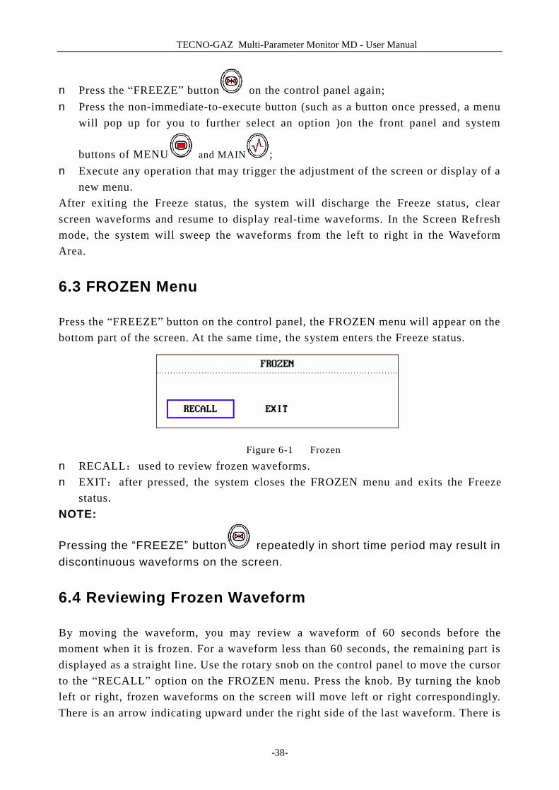
Press the “FREEZE” button on the control panel, the FROZEN menu will appear on the bottom part of the screen. At the same time, the system enters the Freeze status.
Figure 6-1 Frozen
n RECALL:used to review frozen waveforms. n EXIT:after pressed, the system closes the FROZEN menu and exits the Freeze
status. NOTE:
Pressing the “FREEZE” button repeatedly in short time period may result in discontinuous waveforms on the screen.
6.4 Reviewing Frozen Waveform
By moving the waveform, you may review a waveform of 60 seconds before the moment when it is frozen. For a waveform less than 60 seconds, the remaining part is displayed as a straight line. Use the rotary snob on the control panel to move the cursor to the “RECALL” option on the FROZEN menu. Press the knob. By turning the knob left or right, frozen waveforms on the screen will move left or right correspondingly. There is an arrow indicating upward under the right side of the last waveform. There is

TECNO-GAZ Multi-Parameter Monitor MD - User Manual
-39-
also a time scale beside the arrow. “-0S” is used to mark the moment when waveforms are frozen. With waveforms moving right, this time mark will in turn change into -1S, -2S, -3S… These time marks are applied to all waveforms on the screen.
TECNO-GAZ Multi-Parameter Monitor MD - User Manual
-40-
7 Recording (Optional)
n General information on recording n Instructions for configuring and recording n Recording messages
7.1 General Information on Recording
A thermal dot matrices recorder with 48mm wide printout paper is used for Multi-parameter Patient Monitor.
Performance of the Recorder
n Waveform record is printed out at the rate of 25 mm/s or 50 mm/s. n It can record up to 2 waveforms. n English printout. n User-selectable real-time recording time and waveform. n Auto recording interval is set by the user, the waveform is in accordance with the
real time recording.
7.2 Recording Type
Multi-parameter patient monitor provides several stripe recording types:
n Continuous real-time recording n 8 second real-time recording n Auto 8 second recording n Alarm recording n Drug calculation titration recording
Real-time Recording
Real-time recording starts as you press the RECORD button on the recorder.
The waveforms for continuous real-time recording and continuous 8 second recording are automatically set by the monitor (usually the first two waveforms displayed on the screen). You can also configure it through the menu. Refer to related section for details.
TECNO-GAZ Multi-Parameter Monitor MD - User Manual
-41-
In RECORD menu, the user can choose two waveforms to be printed out. The User can setup one waveform off. Thus, the real time record will print out one waveform. If two waveforms are off, the real time record will print out measure parameters only. NOTE: When the system is executing a recording task, the system can start executing next alarm recording task only when the current one is finished.
Auto Recording
The monitor starts the recorder for 8 seconds according to interval time set in the “TIMING REC TIME” of the “RECORD” menu. Refer to Chapter Recorder Setup for details.
Alarm Recording
n Parameter Alarm The monitor records waveforms 4, 8, or 16 seconds prior to and after the alarm (totally 8, 16 or 32 seconds) (which can be selected in System Menu). All parameter values during the alarm will also be recorded. When parameter alarm occurs, two recorded waveforms can be printed out. In order to avoid repeated printout of alarm waveforms: ① If more than two parameter alarms are switched on and triggered simultaneously,
the recorder will print out those of the highest level. If of the same alarm level, the latest alarm will be printed out.
② If an alarm occurs during the alarm of another parameter, it will be printed out after the current recording is finished.
③ If many alarms occur at the same time, some of waveforms will be stored for printout in turn.
n ST Segment Alarm The monitor records 2-channel ECG waveforms 4, 8, or 16 seconds prior to and after the alarm (totally 8, 16 or 32 seconds) (which can be selected in the ECG SETUP menu). All parameter values during the alarm will also be recorded. n Arrhythgmia Alarm The monitor records 2-channel ECG waveforms 4, 8, or 16 seconds prior to and after the alarm (totally 8, 16 or 32 seconds). All measurement results during the alarm will also be recorded.
Titration Table
The monitor can print out the message in the current TITRATION window.
TECNO-GAZ Multi-Parameter Monitor MD - User Manual
-42-
Notes on Recording
n Recording types: Real time Report Periodic Report Para Alarm Report Titration Table
n Patient bed number, name, sex, height, weight, date of birth, admission date n Parameter name and value n Recording time n Waveform name n Waveform scale (for ECG waveform) n ECG lead, scale, filter mode, (if having ECG waveforms, it will be printed out
within the first second or when changing the lead, gain and filter mode during real-time recording.)
n IBP scale (the first second of IBP waveform) n Date and time
7.3 Recording Startup
You can start the recording in the following ways: Continuous real-time recording Press RECORD button to start/stop the recording.
8 second real-time recording Press RECORD button to start recording. It will
automatically stop in 8 seconds. Auto recording Record the two waveforms selected in RECORD menu
according to the setup time interval in RECORD menu. It will automatically stop in 8 seconds.
Alarm recoding When alarm recording is set ON, it automatically starts when alarm occurs.
Titration table recording Access the “DRUG CALC” menu from the “SYSTEM MENU” menu. Pick the “TITRATION” button in the menu to access the “TITRATION” window. Pick the “REC” button to print out the titration currently displayed in the window.
TECNO-GAZ Multi-Parameter Monitor MD - User Manual
-43-
NOTE:
You can press RECORD button on the control panel to stop the current recording process. Access the “RECORD” menu from the “SYSTEM SETUP” menu. Then pick the “CLEAR REC TASK” button to stop all recording tasks.
7.4 Recorder Operations and Status Messages
Record Paper Requirement
Only standard thermosensitive record paper can be used, otherwise the recorder may not function, the recording quality may be poor, and the thermosensitive printhead may be damaged.
Proper Operation
■ When the recorder is working, the record paper goes out steadily. Do not pull the paper outward with force,otherwise the recorder may be damaged.
■ Do not operate the recorder without record paper.
Paper Out
When "RECORDER OUT OF PAPER" alarm is displayed, the recorder cannot start. Please insert record paper properly.
Inserting Paper
■ Place fingers under the two sides flange of the recorder casing, pull outwards directly to release the casing.
■ Insert a new roll of paper into the paper cassette, printing side facing upwards. ■ Ensure proper position and tidy margin. ■ Pull about 2cm of the paper out, then close the recorder casing.
NOTE: Be careful when inserting paper. Avoid damaging the thermo-sensitive print head. Unless when inserting paper or shooting troubles, do not leave the recorder catch open.

TECNO-GAZ Multi-Parameter Monitor MD - User Manual
-44-
Removing Paper Jam
When the recorder functions or sounds improperly, open the recorder casing to check for a paper jam. Removing the paper jam in the following way: ■ Cut the record paper from the feeding edge. ■ Open the recorder casing. ■ Re-insert the paper.
TECNO-GAZ Multi-Parameter Monitor MD - User Manual
-45-
8 Trend and Event
Multi-parameter patient monitor provides 96-hour trend data of all parameters, storage of 500 NIBP measurement results and 60 alarm events. This chapter gives detailed instruction for review of all data.
8.1 Trend Graph
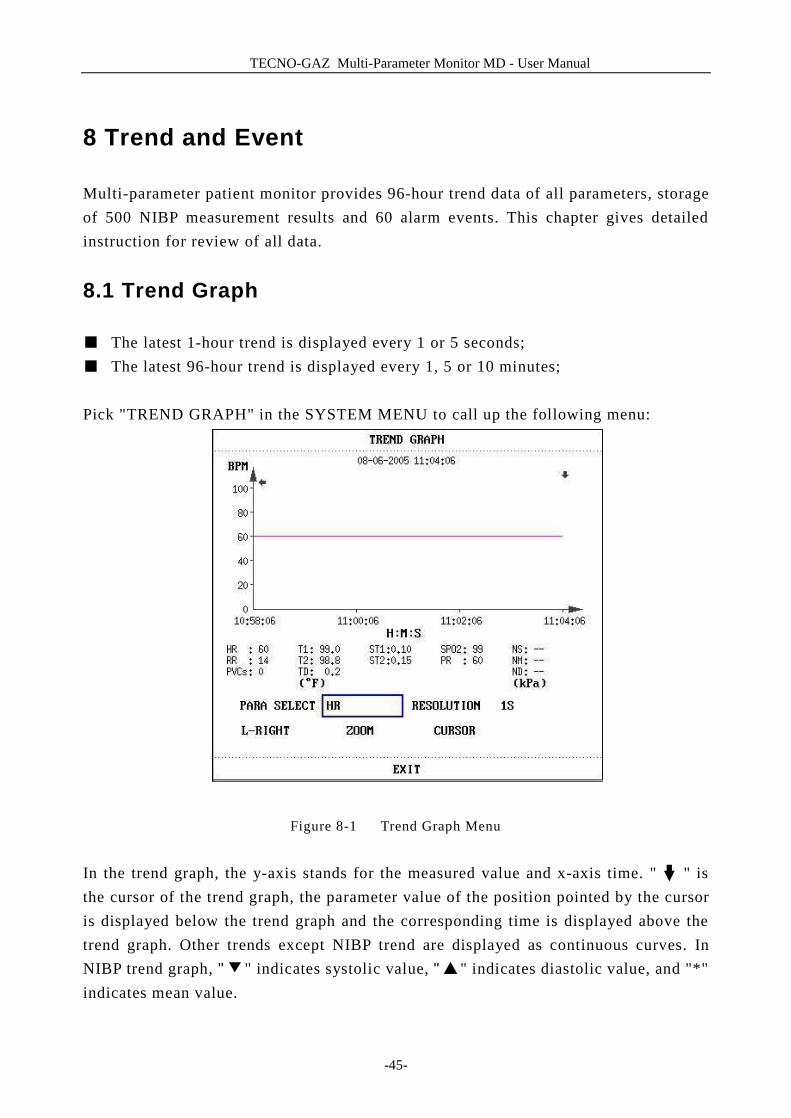
■ The latest 1-hour trend is displayed every 1 or 5 seconds; ■ The latest 96-hour trend is displayed every 1, 5 or 10 minutes; Pick "TREND GRAPH" in the SYSTEM MENU to call up the following menu:
Figure 8-1 Trend Graph Menu
In the trend graph, the y-axis stands for the measured value and x-axis time. " " is the cursor of the trend graph, the parameter value of the position pointed by the cursor is displayed below the trend graph and the corresponding time is displayed above the trend graph. Other trends except NIBP trend are displayed as continuous curves. In NIBP trend graph, "▼" indicates systolic value, "▲" indicates diastolic value, and "*" indicates mean value.
TECNO-GAZ Multi-Parameter Monitor MD - User Manual
-46-
To select trend graph of a specific parameter
Pick PARA SELECT item and select a requested parameter name by turning the knob.
To select 1-hour or 96-hour trend graph
Pick RESOLUTION item, choose 1 or 5 sec for 1-hour trend graph and 1, 5 or 10 min for 96-hour trend graph.
To view other trend curves
When " " appears on the right part of the screen, pick "L-RIGHT", turn the knob clockwise to view later trend curves. When " " appears on the left part of the screen, pick the same item, turn the knob counterclockwise to view earlier trend curve.
To change the display scale
Pick the “ZOOM” button to adjust the y-axis scale and thus change the trend curve in proportion. The value beyond maximum value will be represented by the maximum value.
To obtain trend data of a specific time
The time to which the cursor points will change as the knob is turned. Parameter at this time is displayed below the x-axis. When " " appears on the right part of the screen, the trend graph pages down for later trend curve as the cursor moves here. When " " appears on the left part of the screen, the trend graph pages up for earlier trend curve as the cursor moves here.
Mark Event
If an event is marked A, B, C, or D, then the corresponding event type will display on
the axis time of the trend graph,such as , , or .
Operation Example
To view the NIBP trend graph of the last 1 hour:
n Pick the MENU key on the lower right of the screen. n Pick TREND GRAPH item in the SYSTEM MENU. n Select parameter: pick the PARA item and turn the knob until NIBP appears.
TECNO-GAZ Multi-Parameter Monitor MD - User Manual
-47-
n Select 1S or 5S in the RESOLUTION item. n Pick the L-Right button and turn the knob to view changes of the trend graph time
and trend curve. n Stop at requested trend time section for careful review. Pick the ZOOM button to
adjust the display scale if necessary. n For measurement result of a specific time, pick CURSOR to move the cursor to the
point, corresponding time and value will display on above and below respectively. n Pick EXIT to return to trend graph display.
8.2 Trend Table
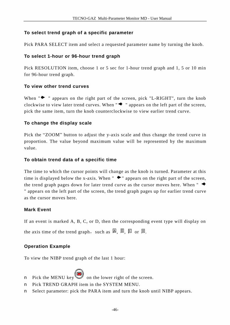
n The latest 96-trend table data can be displayed at every 1, 5, 10, 30, or 60 minutes. Pick TREND TABLE in the SYSTEM MENU to call up the following menu:
Figure 8-2 Trend Table
Time in response to each group of trend data is displayed at the leftmost list with date in bracket. Marked event corresponds to marking time. Trend data of each parameter is divided into 7 groups.
HR, PVC ST1, ST2 RR

TECNO-GAZ Multi-Parameter Monitor MD - User Manual
-48-
T1, T2, TD SPO2, PR NIBP NS/NM/ND IBP1, IBP2
To choose trend table of different resolution
Pick the RESOLUTION item and turn the knob to change its content so as to change the time interval of trend data.
To view other trend data
When " " appears on the upper part of the screen, pick UP-DOWN button and turn the knob counterclockwise to view later trend data. When " " appears on the lower part of the screen, pick the same item and turn the knob clockwise to view earlier trend data.
To obtain trend data of different parameter
Pick L-RIGHT to select one from the 8 groups of parameters. A " " by the rightmost item indicates following page available. And " " by the leftmost item indicated previous page available.
Mark Event
If an event is marked A, B, C, or D, the corresponding event type will display on the axis time of the trend table.
Operation Example
To view a NIBP trend table:
n Pick MENU hot key on the lower right of the screen to access “SYSTEM MENU”.
n Pick TREND TABLE. n Pick L-RIGHT and switch to NIBP by turning the knob. n Pick RESOLUTION to select requested time interval. n Pick UP-DOWN and turn the knob to view NIBP trend data of different time. n Pick EXIT to return to SYSTEM MENU.
TECNO-GAZ Multi-Parameter Monitor MD - User Manual
-49-
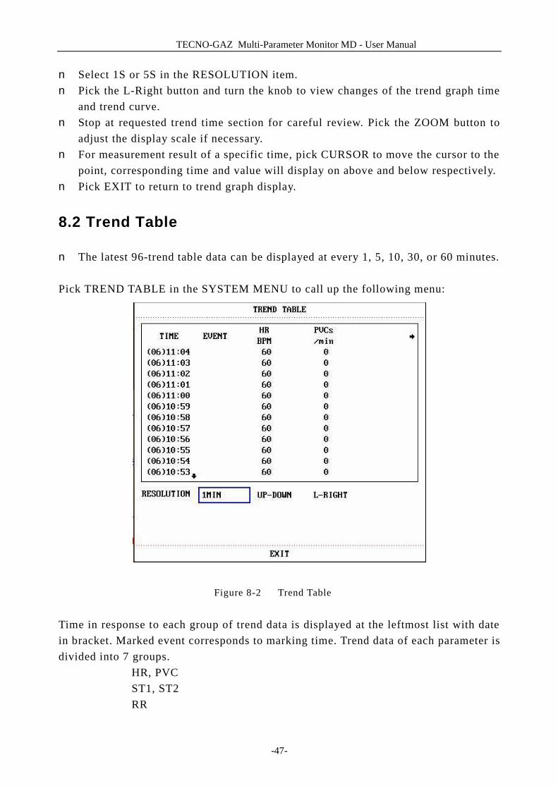
8.3 NIBP Recall
The Multi-parameter patient monitor can review the latest 500 NIBP measurement data. Pick NIBP RECALL in the SYSTEM MENU to invoke the result and time of the latest 15 measurements, as shown in the figure below.
Figure 8-3 NIBP Recall
Data is listed chronologically from the latest to the earliest. 15 measurements can be displayed in one screen. Pick UP-DOWN to view other trend curve up to 500 results. When you press the “RECORD”button,the recorder will pint out the metrical data of current window.
8.4 Alarm Event Recall
The Multi-parameter patient monitor can display the latest 60 alarm events. n Select “ALARM RECALL” in the SYSTEM MENU to access ALARM RECALL
CONDITION menu as shown below.
TECNO-GAZ Multi-Parameter Monitor MD - User Manual
-50-
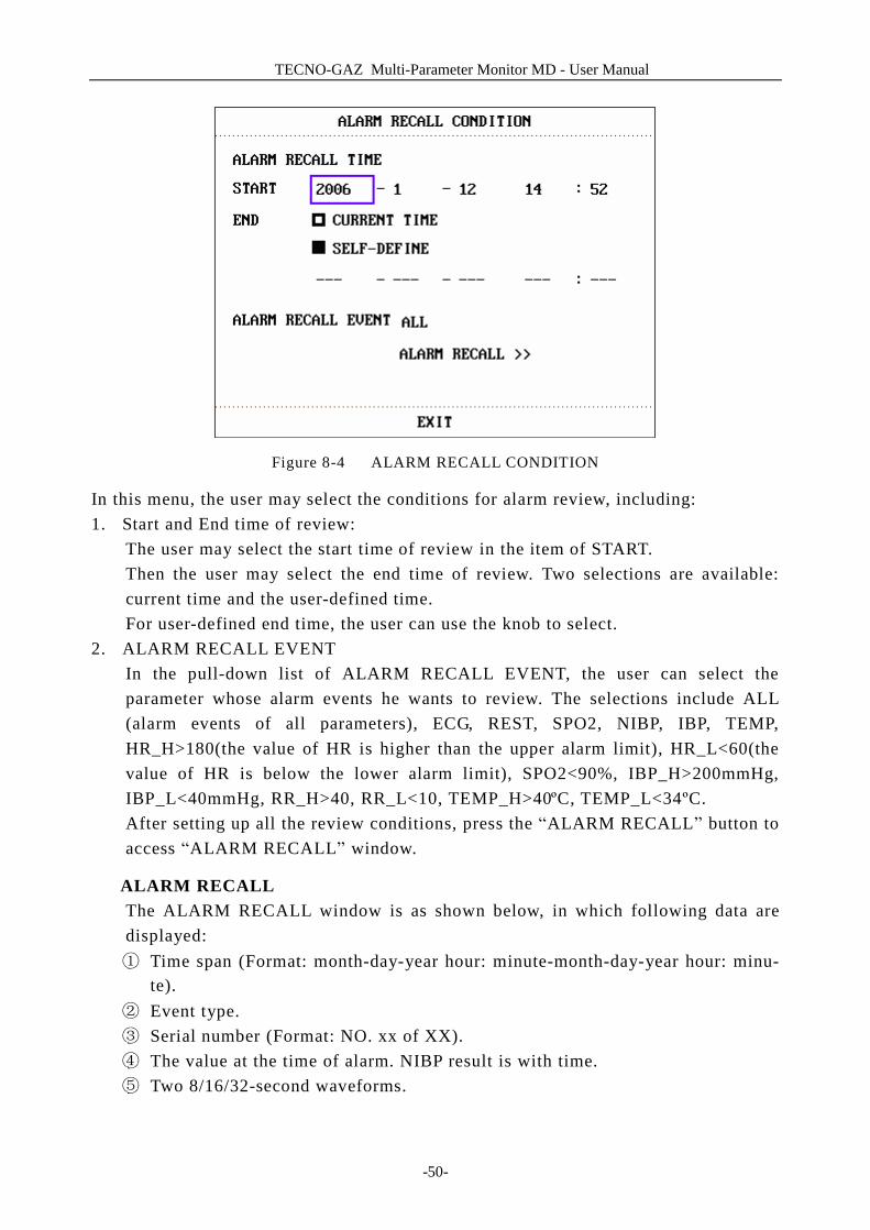
Figure 8-4 ALARM RECALL CONDITION
In this menu, the user may select the conditions for alarm review, including: 1. Start and End time of review:
The user may select the start time of review in the item of START. Then the user may select the end time of review. Two selections are available: current time and the user-defined time. For user-defined end time, the user can use the knob to select.
2. ALARM RECALL EVENT In the pull-down list of ALARM RECALL EVENT, the user can select the parameter whose alarm events he wants to review. The selections include ALL (alarm events of all parameters), ECG, REST, SPO2, NIBP, IBP, TEMP, HR_H>180(the value of HR is higher than the upper alarm limit), HR_L<60(the value of HR is below the lower alarm limit), SPO2<90%, IBP_H>200mmHg, IBP_L<40mmHg, RR_H>40, RR_L<10, TEMP_H>40ºC, TEMP_L<34ºC. After setting up all the review conditions, press the “ALARM RECALL” button to access “ALARM RECALL” window.
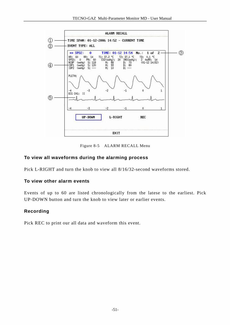
ALARM RECALL The ALARM RECALL window is as shown below, in which following data are displayed: ① Time span (Format: month-day-year hour: minute-month-day-year hour: minu-
te). ② Event type. ③ Serial number (Format: NO. xx of XX). ④ The value at the time of alarm. NIBP result is with time. ⑤ Two 8/16/32-second waveforms.
TECNO-GAZ Multi-Parameter Monitor MD - User Manual
-51-
Figure 8-5 ALARM RECALL Menu
To view all waveforms during the alarming process
Pick L-RIGHT and turn the knob to view all 8/16/32-second waveforms stored.
To view other alarm events
Events of up to 60 are listed chronologically from the latese to the earliest. Pick UP-DOWN button and turn the knob to view later or earlier events.
Recording
Pick REC to print our all data and waveform this event.
TECNO-GAZ Multi-Parameter Monitor MD - User Manual
-52-
9 Drug Calculation and Titration Table (Optional)
Multi-parameter patient monitor provides Drug calculation and titration table display functions for fifteen drugs and outputs the content of titration table on the recorder.
9.1 Drug Calculation
The drug calculations that can be performed by the system are AMINOPHYLLINE, DOBUTAMINE, DOPAMINE, EPINEPHRINE, HEPARIN, ISUPREL, LIDOCAINE, NIPRIDE, NITROGLYCERIN and PITOCIN. Besides DRUG A, DRUG B, DRUG C, DRUG D and DRUG E are also provided to flexibly replace any of the drugs.
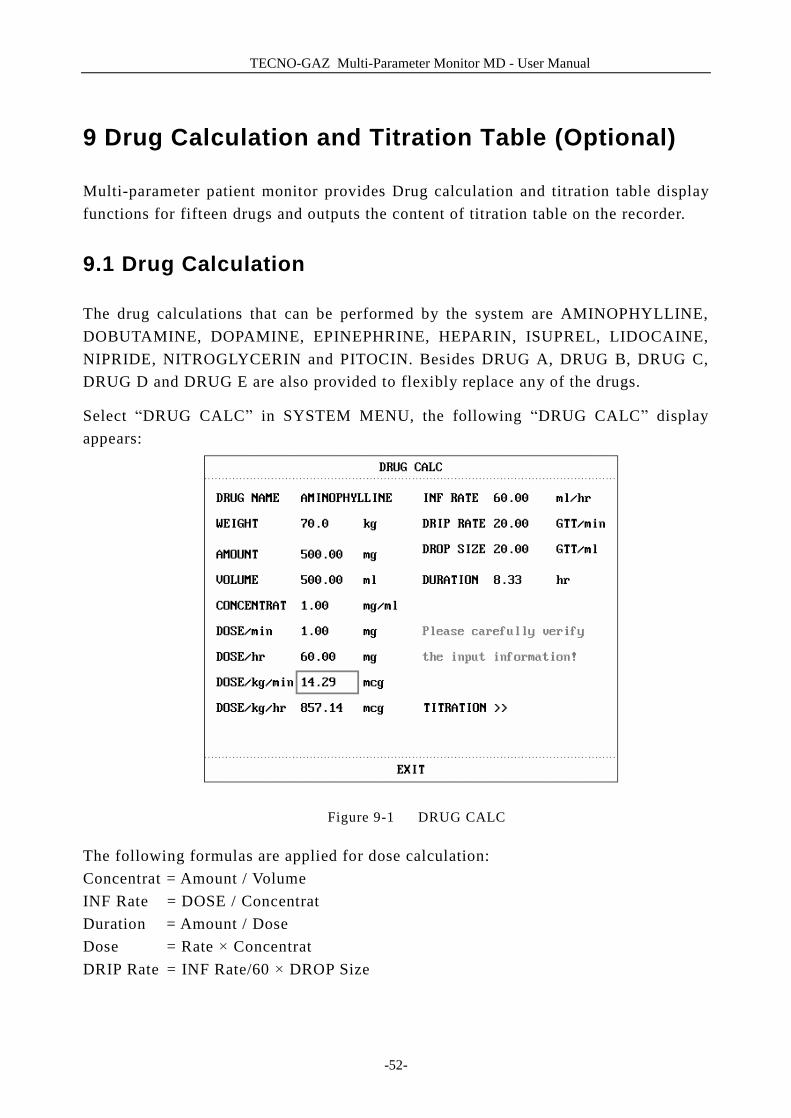
Select “DRUG CALC” in SYSTEM MENU, the following “DRUG CALC” display appears:
Figure 9-1 DRUG CALC
The following formulas are applied for dose calculation: Concentrat = Amount / Volume INF Rate = DOSE / Concentrat Duration = Amount / Dose Dose = Rate × Concentrat DRIP Rate = INF Rate/60 × DROP Size
TECNO-GAZ Multi-Parameter Monitor MD - User Manual
-53-
Operating Method:
In the Drug Calculation window, the operator should first select the name of the drug to be calculated, and then confirm the patient weight. Afterwards, the operator should also enter other known values.
Turn the knob to select the value of the item to be calculated. Turn the knob to change the value. When it is the required value, press the knob to view the calculation result. Each item has its calculation range. If the result exceeds the range, display “---.--”.
NOTE: For the drug calculation, the prerequisite is that the operator must first of all enter the patient weight and drug name. The system first gives a group of random initial values, which cannot be used by the operator as the calculation reference. Instead, he should enter a new group of values at the doctor ’s instruction.
NOTE: Each drug has its fixed unit or unit series. Operator must select the proper unit at the doctor ’s instruction. If the result exceeds the system-defined range, it will display “---”.
NOTE: After entering a value, a conspicuous prompt will appear in the menu warning the operator to confirm the correctness of the entered value. The correct value is the guarantee for the reliability and safety of the calculated results.
NOTE: For each entered value, the system will always give a dialog box asking for the user ’s confirmation. You must be careful when answering each box. The calculated result is reliable only after the entered value is confirmed to be correct.
Select the Drug Name:
Turn the knob to pick the DRUG NAME item in DRUG CALC menu. The user may select the drug name in the pull-down list, including AMINOPHYLLINE 、DOBUTAMINE、DOPAMINE、EPINEPHRINE、HEPARIN、ISUPREL、LIDOCAINE、NIPRIDE、NITROGLYCERIN、PITOCIN、Drug A、Drug B、Drug C、Drug D and Drug E. Calculation for only one type can be generated each time. NOTE: A、B、C、D、E are only codes for drugs instead of their real names. The units for these five drugs are fixed. The operator may select the appropriate units

TECNO-GAZ Multi-Parameter Monitor MD - User Manual
-54-
according to the convention of using these drugs. The rules for expressing the units are:
“mg” series units are fixedly used for drug A, B and C: g, mg, mcg. “unit” series units are fixedly used for drug D: unit, k unit, m unit. “mEq” is fixedly used for drug E.
Patient Weight:
After accessing the DRUG CALC window, the operator should enter the patient weight into the first or the second item. The entered weight will be used as the independent data only for the calculation of drug concentration.
NOTE: This drug calculation function acts only as a calculator. That means the patient weight in Drug Calculation menu and the patient weight in Patient Information menu are independent from each other.Therefore if the Weight in Drug Calcu- lation changes, the Weight in Patient Information does not change. In this way, we can say, the Drug Calculation menu is independent from other menus in the system. Any change of it will not affect other information about the patient being currently monitored.
9.2 Titration Table
Access Titration Table:
Select TITRATION item in DRUG CALC menu to enter titration table display. Titration table display for drug is as following:
TECNO-GAZ Multi-Parameter Monitor MD - User Manual
-55-
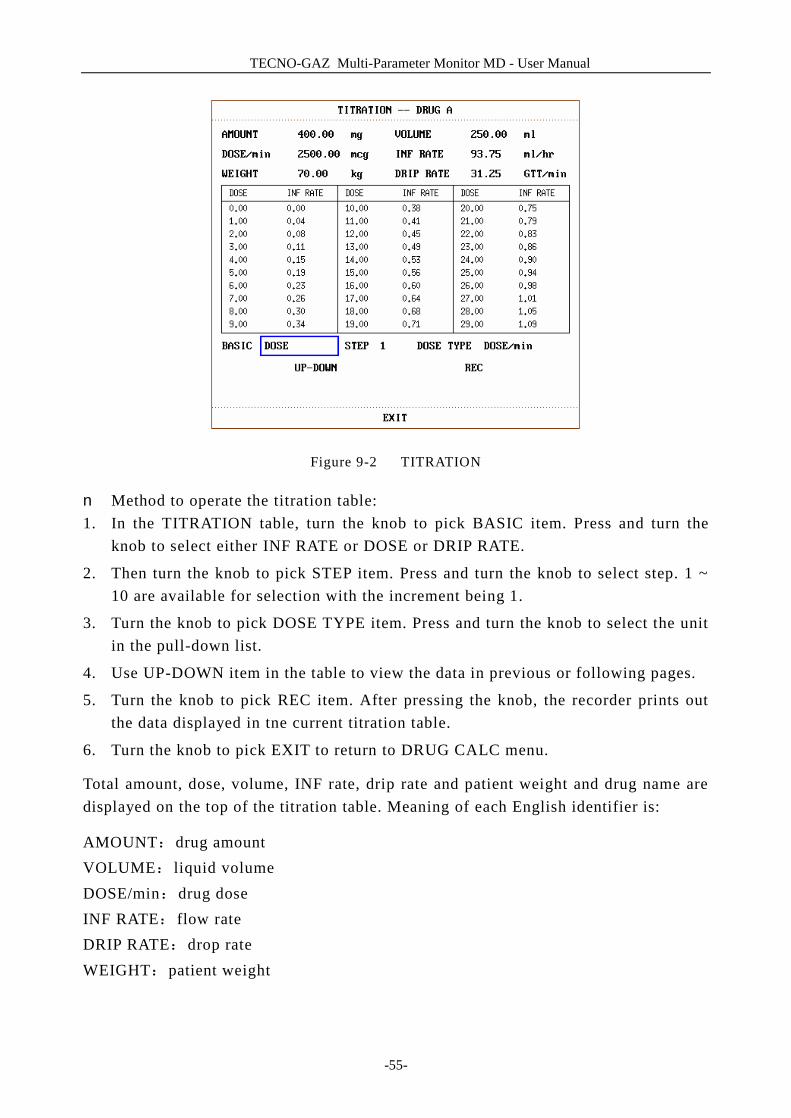
Figure 9-2 TITRATION
n Method to operate the titration table: 1. In the TITRATION table, turn the knob to pick BASIC item. Press and turn the
knob to select either INF RATE or DOSE or DRIP RATE.
2. Then turn the knob to pick STEP item. Press and turn the knob to select step. 1 ~ 10 are available for selection with the increment being 1.
3. Turn the knob to pick DOSE TYPE item. Press and turn the knob to select the unit in the pull-down list.
4. Use UP-DOWN item in the table to view the data in previous or following pages.
5. Turn the knob to pick REC item. After pressing the knob, the recorder prints out the data displayed in tne current titration table.
6. Turn the knob to pick EXIT to return to DRUG CALC menu.
Total amount, dose, volume, INF rate, drip rate and patient weight and drug name are displayed on the top of the titration table. Meaning of each English identifier is:
AMOUNT:drug amount VOLUME: liquid volume DOSE/min:drug dose INF RATE: flow rate DRIP RATE:drop rate WEIGHT:patient weight
TECNO-GAZ Multi-Parameter Monitor MD - User Manual
-56-
10 Safety Guidance
The Multi-parameter Patient Monitor is designed to comply with the International National Safety requirements for medical electrical equipment IEC60601-1, EN60601-2-27 and EN60601-2-30. This device has floating inputs and is protected against the effects of defibrillation and electrosurgery. If the correct electrodes are used and applied in accordance with the manufacturer instructions (see Chapter ECG/RESP Monitoring), the system can restore screen display within 10 seconds after defibrillation.
This symbol indicates that the instrument is IEC 60601-1 Type CF equipment. The unit displaying this symbol contains an F-Type isolated (floating) patient applied part providing a high degree of protection against shock, and is suitable for use during defibrillation.
Environment
Follow the instructions below to ensure a completely safe electrical installation. The environment where the Multi-parameter Patient Monitor will be used should be reasonably free from vibration, dust, corrosive or explosive gases, extremes of temperature, humidity, and so on. For a cabinet mounted installation, allow sufficient room at the front for operation and sufficient room at the rear for servicing with the cabinet access door open.
The Multi-parameter Patient Monitor operates within specifications at ambient temperatures between 5℃ and 40℃ . Ambient temperatures that exceed these limits could affect the accuracy of the instrument and cause damage to the modules and circuits. Allow at least 2 inches (5cms) clearance around the instrument for proper air circulation.
Power Source Requirements
Refer to APPENDIX Ⅰ .
Grounding the Multi-parameter Patient Monitor
To protect the patient and hospital personnel, the cabinet of the Multi-parameter Patient Monitor must be grounded. Accordingly, the Multi-parameter Patient Monitor is equipped with a detachable 3-wire cable which grounds the instrument to the power
TECNO-GAZ Multi-Parameter Monitor MD - User Manual
-57-
line ground (protective earth) when plugged into an appropriate 3-wire receptacle. If a 3-wire receptacle is not available, consult the hospital electrician.
Connect the grounding wire to the equipotential grounding terminal on the main system. If it is not evident from the instrument specifications whether a particular instrument combination is hazardous or not, for example due to summation of leakage currents, the user should consult the manufacturers concerned or else an expert in the field, to ensure that the necessary safety of all instruments concerned will not be impaired by the proposed combination.
Equipotential Grounding
Protection class 1 instruments are already included in the protective grounding (protective earth) system of the room by way of grounding contacts in the power plug. For internal examinations on the heart or the brain, the Multi-parameter Patient Monitor must have a separate connection to the equipotential grounding system. One end of the equipotential grounding cable (potential equalization conductor) is connected to the equipotential grounding terminal on the instrument rear panel and the other end to one point of the equipotential grounding system. The equipotential grounding system assumes the safety function of the protective grounding conductor if ever there is a break in the protective grounding system. Examinations in or on the heart (or brain) should only be carried out in medically used rooms incorporating an equipotential grounding system. Check each time before use that the instrument is in perfect working order. The cable connecting the patient to the instrument must be free of electrolyte.
WARNING If the protective grounding (protective earth) system is doubtful, the monitor must be supplied by inner power only.
Condensation
Make sure that during operation, the instrument is free of condensation. Condensation can form when equipment is moved from one building to another, thus being exposed to moisture and differences in temperature.
Safety Precautions
WARNING and CAUTION messages must be observed. To avoid the possibility of injury, observe the following precautions during the operation of the instrument.
TECNO-GAZ Multi-Parameter Monitor MD - User Manual
-58-
WARNING The patient monitor is provided for the use of qualified physicians or personnel professionally trained. And they should be familiar with the contents of this user manual before operation.
WARNING Only qualified service engineers can install this equipment.
WARNING EXPLOSION HAZARD- Do not use the device in a flammable atmosphere where concentrations of flammable anesthetics or other materials may occur.
WARNING SHOCK HAZARD- the power receptacle must be a three-wire grounded outlet. A hospital grade outlet is required. Never adapt the three-prong plug from the monitor to fit a two-slot outlet.
WARNING SHOCK HAZARD-Do not attempt to connect or disconnect a power cord with wet hands. Make certain that your hands are clean and dry before touching a power cord.
WARNING Accessory equipment connected to the analog and digital interfaces must be certified according to the respective IEC standards (e.g. IEC 950 for data processing equipment and IEC 60601-1 for medical equipment). Furthermore all configurations shall comply with the valid version of the system standard IEC 60601-1-1. Everybody who connects additional equipment to the signal input connector or signal output connector configures a medical system, and is therefore responsible that the system complies with the requirements of the valid version of the system standard IEC 60601-1-1. If in doubt, consult our technical service department or your local distributor.
WARNING Before using the rechargeable lithium-ion battery (hereinafter called battery), be sure to read the user manual and safety precautions thoroughly.
WARNING Do not place battery in the monitor with the (+) and (-) in the wrong way around.
TECNO-GAZ Multi-Parameter Monitor MD - User Manual
-59-
WARNING Don’t connect the positive (+) and negative (-) terminals with metal objects, and don’t put the battery together with metal object, which can result in short circuit.
WARNING Do not unplug the battery when monitoring.
WARNING Do not heat or throw battery into a fire.
WARNING Do not use, leave battery close to fire or other places where temperature may be above 60℃ .
WARNING Do not immerse, throw, and wet battery in water/ seawater.
WARNING Do not destroy the battery: Do not pierce battery with a sharp object such as a needle; Do not hit with a hammer, step on or throw or drop to cause strong shock; Do not disassemble or modify the battery.
WARNING Use the battery only in the MD multi-parameter patient monitor. Do not connect battery directly to an electric outlet or cigarette lighter charger.
WARNING Don’t solder the leading wire and the battery terminal directly.
WARNING If liquid leaking from the battery gets into your eyes, do not rub your eyes. Wash them well with clean water and go to see a doctor immediately.
WARNING If liquid leaks of the battery onto your skin or clothes, wash well with fresh water immediately.
WARNING Keep away from fire immediately when leakage or foul odor is detected.
TECNO-GAZ Multi-Parameter Monitor MD - User Manual
-60-
WARNING Stop using the battery if abnormal heat, odor, discoloration, deformation or abnormal condition is detected during use, charge, or storage. Keep it away from the monitor.
WARNING Do not use a battery with serious scar or deformation.
WARNING Only patient cable and other accessories supplied by TecnoGaz can be used. Or else, the performance and electric shock protection can not be guaranteed.
WARNING The user should check the monitor and accessories before use.
WARNING Be sure that all electrodes have been connected to the patient correctly before operation.
WARNING When connecting the cables and electrodes, make sure no conductive part is in contact with the ground. Verify that all ECG electrodes, including neutral electrodes, are securely attached to the patient.
WARNING Do not touch the patient, bed or instrument during defibrillation.
WARNING Please set the alarm according to the individual status of patient to avoid delaying treatment. Ensure there will be alarm audio prompt when alarming.
WARNING Devices connecting with monitor should be equipotential.
WARNING When the monitor and electrosurgical device are used together, the user (physician or nurse) should guarantee the safety of patient.
WARNING Please sterilize and disinfect timely to prevent the cross infection between patients.
TECNO-GAZ Multi-Parameter Monitor MD - User Manual
-61-
CAUTION
Electromagnetic Interference- Ensure that the environment in which the patient monitor is installed is not subject to any sources of strong electromagnetic interference, such as radio transmitters, mobile telephones, etc.
CAUTION
The device is designed for continuous and is “ordinary” (i.e. not drip or splash-proof).
CAUTION
Keep the environment clean. Avoid vibration. Keep it far from corrosive medicine, dust area, high-temperature and humid environment.
CAUTION
Do not immerse transducers in liquid. When using solutions, use sterile wipes to avoid pouring fluids directly on the transducer.
CAUTION
Do not autoclave or gas sterilize the monitor, recorder or any accessories.
CAUTION
The device and reusable accessories could be sent back to the manufacturer for recycling or proper disposal after their useful lives.
CAUTION
Remove a battery whose life cycle has expired from the monitor immediately.
CAUTION
Avoid liquid splash and excessive temperature. The temperature must be kept between 5℃ and 40℃ while working. And it should be kept between -20℃ and 55℃ during transportation and storage.
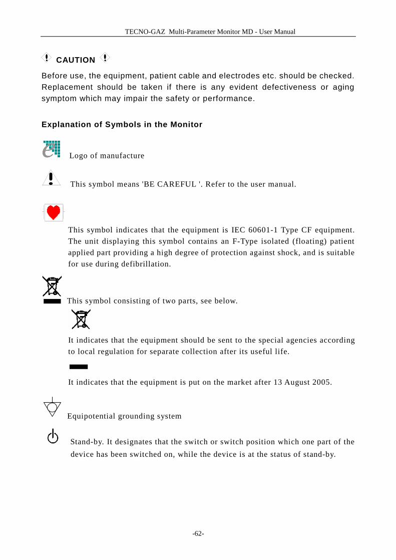
TECNO-GAZ Multi-Parameter Monitor MD - User Manual
-62-
CAUTION
Before use, the equipment, patient cable and electrodes etc. should be checked. Replacement should be taken if there is any evident defectiveness or aging symptom which may impair the safety or performance.
Explanation of Symbols in the Monitor
Logo of manufacture
This symbol means 'BE CAREFUL '. Refer to the user manual.
This symbol indicates that the equipment is IEC 60601-1 Type CF equipment. The unit displaying this symbol contains an F-Type isolated (floating) patient applied part providing a high degree of protection against shock, and is suitable for use during defibrillation.
This symbol consisting of two parts, see below.
It indicates that the equipment should be sent to the special agencies according to local regulation for separate collection after its useful life.
It indicates that the equipment is put on the market after 13 August 2005.
Equipotential grounding system
Stand-by. It designates that the switch or switch position which one part of the device has been switched on, while the device is at the status of stand-by.
TECNO-GAZ Multi-Parameter Monitor MD - User Manual
-63-
11 Maintenance / Cleaning
11.1 System Check
Before using the monitor, do the following: ■ Check if there is any mechanical damage; ■ Check if all the outer cables, inserted modules and accessories are in good
condition; ■ Check all the functions of the monitor to make sure that the monitor is in good
condition. If you find any damage on the monitor, stop using the monitor on patient, and contact the biomedical engineer of the hospital or Customer Service immediately. The overall check of the monitor, including the safety check, should be performed only by qualified personnel once every 6 to 12 month, and each time after fix up. All the checks that need to open the monitor should be performed by qualified customer service technician. The safety and maintenance check can be conducted by persons from this company. You can obtain the material about the customer service contract from the local company’s office.
WARNING If the hospital or agency that is responding to using the monitor does not follow a satisfactory maintenance schedule, the monitor may become invalid, and the human health may be endangered.
NOTE: To prolong the life of chargeable battery, charging it once every month at least is recommended, and it must be done after the electric energy is run out.
WARNING Replace batteries according to the instruction of our servicing engineer.
11.2 General Cleaning

TECNO-GAZ Multi-Parameter Monitor MD - User Manual
-64-
WARNING Before cleaning the monitor or the sensor, make sure that the equipment is switched off and disconnected from the power line.
The Multi-parameter Patient Monitor must be kept dust-free. Regular cleaning of the monitor shell and the screen is strongly recommended. Use only non-caustic detergents such as soap and water to clean the monitor shell.
CAUTION
Please pay special attention to the following items: 1. Avoid using ammonia-based or acetone-based cleaners such as acetone. 2. Most cleaning agents must be diluted before use. Follow the manufacturer's directions carefully to avoid damaging the monitor. 3. Don't use the grinding material, such as steel wool etc. 4. Don't let the cleaning agent enter into the chassis of the system. 5. Don't leave the cleaning agents at any part of the equipment.
11.3 Cleaning Agents
Examples of disinfectants that can be used on the instrument casing are listed below: ■ Diluted Ammonia Water ■ Diluted Sodium Hyoichlo (Bleaching agent). NOTE: The diluted sodium hyoichlo from 500ppm (1:100 diluted bleaching agent) to 5000ppm (1:10 bleaching agents) is very effective. The concentration of the diluted sodium hyocihlo depends on how many organisms (blood, mucus) on the surface of the chassis to be cleaned. ■ Diluted Formaldehyde 35% -- 37% ■ Hydrogen Peroxide 3% ■ Alcohol ■ Isopropanol NOTE: Multi-parameter Patient Monitor and sensor surface can be cleaned with hospital-grade ethanol and dried in air or with crisp and clean cloth.
TECNO-GAZ Multi-Parameter Monitor MD - User Manual
-65-
NOTE: This company has no responsibility for the effectiveness of controlling infectious disease using these chemical agents. Please contact infectious disease experts in your hospital for details.
11.4 Sterilization
To avoid extended damage to the equipment, sterilization is only recommended when stipulated as necessary in the Hospital Maintenance Schedule. Sterilization facilities should be cleaned first.
Recommended sterilization material: Ethylate, and Acetaldehyde. Appropriate sterilization materials for ECG lead, blood pressure cuff are introduced in relative chapters respectively.
WARNING Please sterilize and disinfect timely to prevent the cross infection between patients.
CAUTION
n Follow the manufacturer ’s instruction to dilute the solution, or adopt the lowest possible density.
n Do not let liquid enter the monitor. n No part of this monitor can be subjected to immersion in liquid. n Do not pour liquid onto the monitor during sterilization. n Use a moistened cloth to wipe up any agent remained on the monitor.
11.5 Disinfection
To avoid extended damage to the equipment, disinfection is only recommended when stipulated as necessary in the Hospital Maintenance Schedule. Disinfection facilities should be cleaned first. Appropriate disinfection materials for ECG lead, SpO2 sensor, blood pressure cuff, TEMP probe, IBP sensor are introduced in relative chapters respectively.
CAUTION
Do not use EtO gas or formaldehyde to disinfect the monitor.
TECNO-GAZ Multi-Parameter Monitor MD - User Manual
-66-
11.6 Replacement of Fuse
Unscrew the fuse cap anticlockwise, replace the fuse (protector tube) and screw down the fuse cap clockwise. Fuse size: Ф5x20 Rated value: T1.6AL/250V. NOTE: Switch off the power switch of the patient monitor before examining the fuse.
TECNO-GAZ Multi-Parameter Monitor MD - User Manual
-67-
12 ECG/RESP Monitoring
12.1 What Is ECG Monitoring
Monitoring the ECG produces a continuous waveform of the patient's cardiac electric activity to enable an accurate assessment of his current physiological state. Only proper connection of the ECG cables can ensure satisfactory measurement. On the Normal Display, The monitor provides display of 2-channel ECG waveforms.
■ The patient cable consists of 2 parts The cable that connects to the monitor;
The lead set that connects to the patient. ■ Using a 3-lead set, one waveform is displayed on the screen. Using a 5-lead set, the
ECG can derive up to two waveforms from two different leads. For requested lead, you may choose from the left side of ECG waveform.
■ The monitor displays the Heart Rate (HR), ST segment and Arrhythmia analysis. ■ All of the parameters above can be set as alarm parameters. NOTE: In the default settings of the monitor, the ECG waveforms are the first two waveforms from top in the Waveform Area.
12.2 Precautions during ECG Monitoring
WARNING Do not come into contact with the patient, table, or the monitor during defibrillation.
WARNING Use only the original ECG cable for monitoring.
WARNING When connecting the cables and electrodes, make sure no conductive part is in contact with the ground. Verify that all ECG electrodes, including neutral electrodes, are securely attached to the patient but not the conductive part or ground.
TECNO-GAZ Multi-Parameter Monitor MD - User Manual
-68-
NOTE:
Interference from a non-grounded instrument near the patient and ESU interference can cause inaccuracy of the waveform.
EN60601-1-2 (protection against radiation is 3v/m) specifies that the electrical field density exceeding 1v/m may cause measurement error in various frequencies. It is accordingly suggested that do not use equipment generating electrical radiation near ECG/RESP monitoring devices.
NOTE:
The simultaneous use of cardiac pacemaker or other patient-connected equipments does not cause safety hazard.
12.3 Monitoring Procedure
12.3.1 Preparation
1. Prepare the patient's skin prior to placing the electrodes. ■ The skin is a poor conductor of electricity, therefore preparation of the patient's
skin is important to facilitate good electrode contact to skin. ■ Shave hair from sites, if necessary. ■ Wash sites thoroughly with soap and water. (Never use ether or pure alcohol,
because this increases skin impedance). ■ Rub the skin briskly to increase capillary blood flow in the tissues and remove
skin scurf and grease. 2. Attach clip or snap to electrodes prior to placement. 3. Put the electrodes on the patient. Before attaching, apply some conductive jelly on
the electrodes if the electrodes are not electrolyte self-supplied. 4. Connect the electrode lead to the patient's cable. 5. Make sure the monitor is ready with power supply.
WARNING Placed the electrode carefully and make sure contact good.
WARNING Check everyday whether there is skin irritation resulted from the ECG electrodes. If so, replace electrodes every 24 hours or change their sites.
WARNING Check if the lead connection is correct before monitoring. Unplug the ECG cable

TECNO-GAZ Multi-Parameter Monitor MD - User Manual
-69-
from the socket, the screen will display the error message “ECG LEAD OFF” and the audible alarm is activated. NOTE: For protecting environment, the electrodes must be recycled or disposed of properly.
12.3.2 Installing ECG Lead
Placing the Electrodes for ECG Monitoring
Electrode placement for 3-lead set (Figure 12-1) ■ Red (R) electrode - Be placed near the right shoulder, directly below the clavicle. ■ Yellow (L) electrode - Be placed near the left shoulder, directly below the clavicle. ■ Green (F) electrode - Be placed on the left hypogastrium. NOTE: the following table gives the corresponding lead names used in Europe and America respectively. (Lead names are represented by R, L, F in Europe, whose corresponding lead names in America are RA, LA, LL.)
America Euro
Lead names color Lead names color
RA White R Red
LA Black L Yellow
LL Red F Green
Figure 12-1 Electrode Placement for 3-lead Set
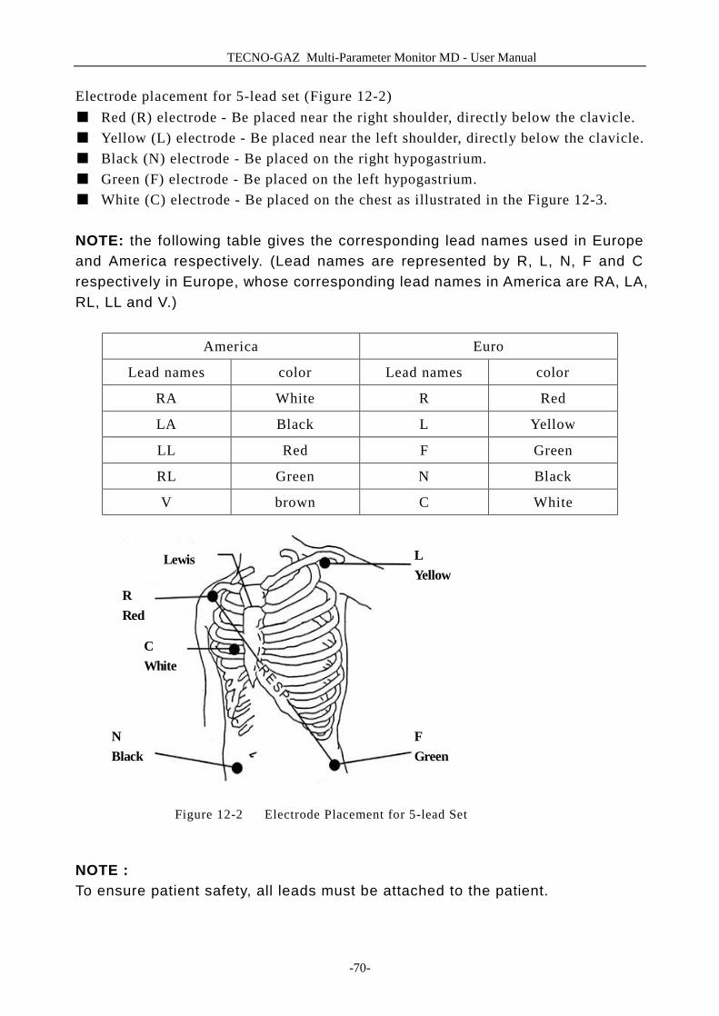
TECNO-GAZ Multi-Parameter Monitor MD - User Manual
-70-
Electrode placement for 5-lead set (Figure 12-2) ■ Red (R) electrode - Be placed near the right shoulder, directly below the clavicle. ■ Yellow (L) electrode - Be placed near the left shoulder, directly below the clavicle. ■ Black (N) electrode - Be placed on the right hypogastrium. ■ Green (F) electrode - Be placed on the left hypogastrium. ■ White (C) electrode - Be placed on the chest as illustrated in the Figure 12-3.
NOTE: the following table gives the corresponding lead names used in Europe and America respectively. (Lead names are represented by R, L, N, F and C respectively in Europe, whose corresponding lead names in America are RA, LA, RL, LL and V.)
America Euro
Lead names color Lead names color
RA White R Red
LA Black L Yellow
LL Red F Green
RL Green N Black
V brown C White
Figure 12-2 Electrode Placement for 5-lead Set
NOTE : To ensure patient safety, all leads must be attached to the patient.
RRed
CWhite
NBlack
LYellow
FGreen
Lewis
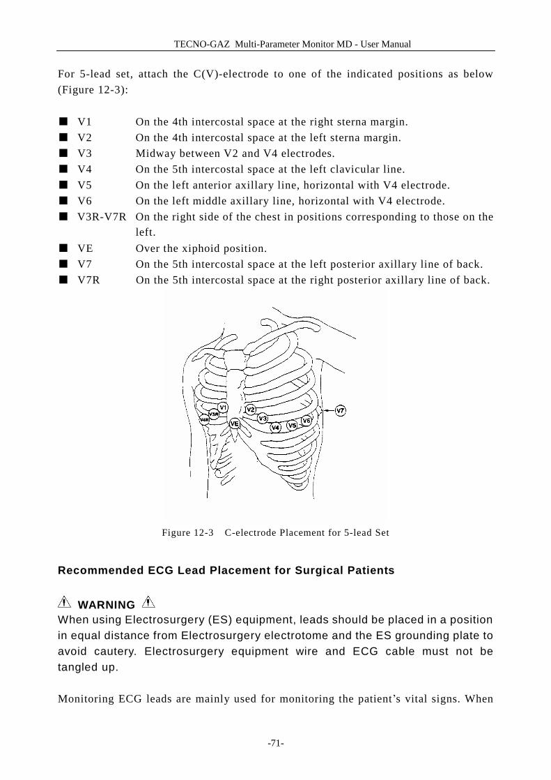
TECNO-GAZ Multi-Parameter Monitor MD - User Manual
-71-
For 5-lead set, attach the C(V)-electrode to one of the indicated positions as below (Figure 12-3): ■ V1 On the 4th intercostal space at the right sterna margin. ■ V2 On the 4th intercostal space at the left sterna margin. ■ V3 Midway between V2 and V4 electrodes. ■ V4 On the 5th intercostal space at the left clavicular line. ■ V5 On the left anterior axillary line, horizontal with V4 electrode. ■ V6 On the left middle axillary line, horizontal with V4 electrode. ■ V3R-V7R On the right side of the chest in positions corresponding to those on the
left. ■ VE Over the xiphoid position. ■ V7 On the 5th intercostal space at the left posterior axillary line of back. ■ V7R On the 5th intercostal space at the right posterior axillary line of back.
Figure 12-3 C-electrode Placement for 5-lead Set
Recommended ECG Lead Placement for Surgical Patients
WARNING When using Electrosurgery (ES) equipment, leads should be placed in a position in equal distance from Electrosurgery electrotome and the ES grounding plate to avoid cautery. Electrosurgery equipment wire and ECG cable must not be tangled up. Monitoring ECG leads are mainly used for monitoring the patient’s vital signs. When
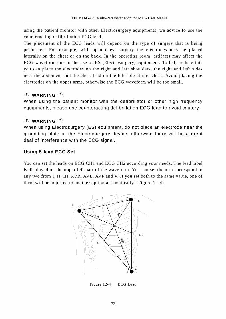
TECNO-GAZ Multi-Parameter Monitor MD - User Manual
-72-
using the patient monitor with other Electrosurgery equipments, we advice to use the counteracting defibrillation ECG lead. The placement of the ECG leads will depend on the type of surgery that is being performed. For example, with open chest surgery the electrodes may be placed laterally on the chest or on the back. In the operating room, artifacts may affect the ECG waveform due to the use of ES (Electrosurgery) equipment. To help reduce this you can place the electrodes on the right and left shoulders, the right and left sides near the abdomen, and the chest lead on the left side at mid-chest. Avoid placing the electrodes on the upper arms, otherwise the ECG waveform will be too small.
WARNING
When using the patient monitor with the defibrillator or other high frequency equipments, please use counteracting defibrillation ECG lead to avoid cautery.
WARNING When using Electrosurgery (ES) equipment, do not place an electrode near the grounding plate of the Electrosurgery device, otherwise there will be a great deal of interference with the ECG signal.
Using 5-lead ECG Set
You can set the leads on ECG CH1 and ECG CH2 according your needs. The lead label is displayed on the upper left part of the waveform. You can set them to correspond to any two from I, II, III, AVR, AVL, AVF and V. If you set both to the same value, one of them will be adjusted to another option automatically. (Figure 12-4)
F
Figure 12-4 ECG Lead
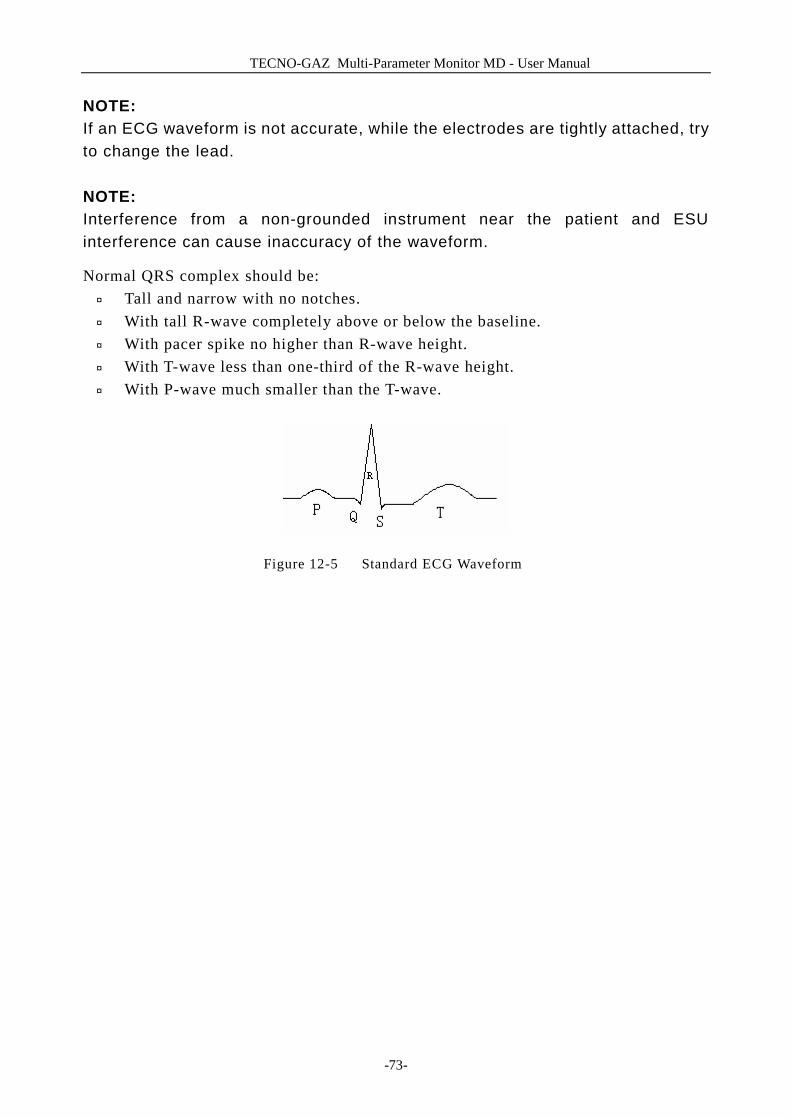
TECNO-GAZ Multi-Parameter Monitor MD - User Manual
-73-
NOTE: If an ECG waveform is not accurate, while the electrodes are tightly attached, try to change the lead. NOTE: Interference from a non-grounded instrument near the patient and ESU interference can cause inaccuracy of the waveform.
Normal QRS complex should be: ¨ Tall and narrow with no notches. ¨ With tall R-wave completely above or below the baseline. ¨ With pacer spike no higher than R-wave height. ¨ With T-wave less than one-third of the R-wave height. ¨ With P-wave much smaller than the T-wave.
Figure 12-5 Standard ECG Waveform

TECNO-GAZ Multi-Parameter Monitor MD - User Manual
-74-
12.4 ECG Screen Hot Keys
Figure 12-6 The Hot Key for ECG
① Leads of channel 1:
1) The selectable leads are I, II, III, aVR, aVL, aVF, V. 2) When the ECG is 5-lead, the selectable leads are: I, II, III, aVR, aVL, aVF, V; when ECG is 3-lead, the selectable leads are: I, II, III. 3) Leads on the ECG wave must not have the same name. Otherwise, the system will automatically change the ECG waveform name that has the same name as the waveform being currently adjusted to another name.
② Waveform gain of channel 1: used to adjust the size of ECG waveforms
Select gain value for each channel from ×0.25,×0.5,×1,×2, and auto. Under "auto" mode, the monitor chooses an appropriate level automatically. A 1mv scale displays on each ECG channel's right side. The height of 1mV bar is directly proportional to the waveform amplitude. NOTE: When the input signals are too large, the peak of the waveform may be not able to be displayed. In this case the user may manually change the setup method of ECG waveform according to the actual waveform so as to avoid the occurrence of the unfavorable phenomena.
③ Filter method: used for displaying clearer and more detailed waveform
④
⑤
② ③ ①
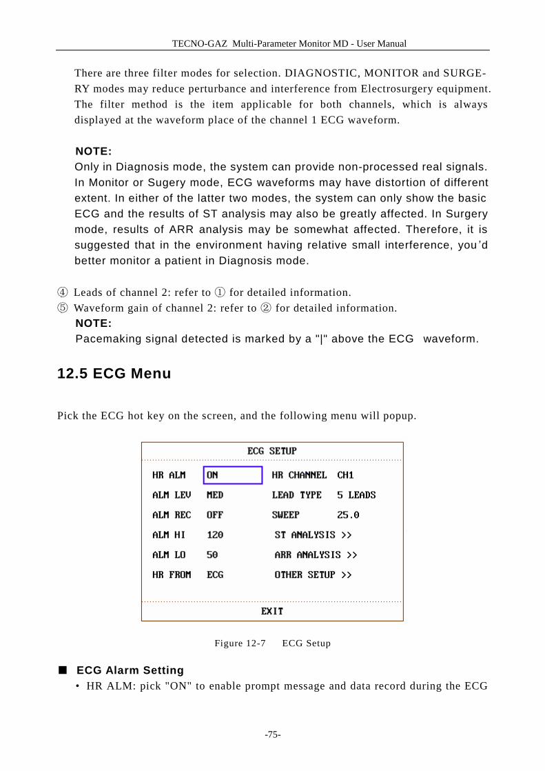
TECNO-GAZ Multi-Parameter Monitor MD - User Manual
-75-
There are three filter modes for selection. DIAGNOSTIC, MONITOR and SURGE- RY modes may reduce perturbance and interference from Electrosurgery equipment. The filter method is the item applicable for both channels, which is always displayed at the waveform place of the channel 1 ECG waveform. NOTE: Only in Diagnosis mode, the system can provide non-processed real signals. In Monitor or Sugery mode, ECG waveforms may have distortion of different extent. In either of the latter two modes, the system can only show the basic ECG and the results of ST analysis may also be greatly affected. In Surgery mode, results of ARR analysis may be somewhat affected. Therefore, it is suggested that in the environment having relative small interference, you ’d better monitor a patient in Diagnosis mode.
④ Leads of channel 2: refer to ① for detailed information. ⑤ Waveform gain of channel 2: refer to ② for detailed information.
NOTE: Pacemaking signal detected is marked by a "|" above the ECG waveform.
12.5 ECG Menu
Pick the ECG hot key on the screen, and the following menu will popup.
Figure 12-7 ECG Setup
■ ECG Alarm Setting • HR ALM: pick "ON" to enable prompt message and data record during the ECG
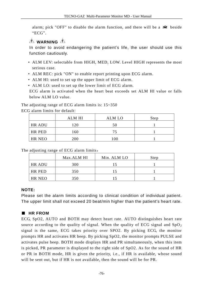
TECNO-GAZ Multi-Parameter Monitor MD - User Manual
-76-
alarm; pick "OFF" to disable the alarm function, and there will be a beside “ECG”.
WARNING In order to avoid endangering the patient’s life, the user should use this function cautiously.
• ALM LEV: selectable from HIGH, MED, LOW. Level HIGH represents the most serious case.
• ALM REC: pick "ON" to enable report printing upon ECG alarm. • ALM HI: used to set up the upper limit of ECG alarm. • ALM LO: used to set up the lower limit of ECG alarm. ECG alarm is activated when the heart beat exceeds set ALM HI value or falls below ALM LO value.
The adjusting range of ECG alarm limits is: 15~350 ECG alarm limits for default:
ALM HI ALM LO Step
HR ADU 120 50 1
HR PED 160 75 1
HR NEO 200 100 1 The adjusting range of ECG alarm limits:
Max.ALM HI Min. ALM LO Step
HR ADU 300 15 1
HR PED 350 15 1
HR NEO 350 15 1 NOTE: Please set the alarm limits according to clinical condition of individual patient. The upper limit shall not exceed 20 beat/min higher than the patient's heart rate. ■ HR FROM ECG, SpO2, AUTO and BOTH may detect heart rate. AUTO distinguishes heart rate source according to the quality of signal. When the quality of ECG signal and SpO 2 signal is the same, ECG takes priority over SPO2. By picking ECG, the monitor prompts HR and activates HR beep. By picking SpO2, the monitor prompts PULSE and activates pulse beep. BOTH mode displays HR and PR simultaneously, when this item is picked, PR parameter is displayed to the right side of SpO2. As for the sound of HR or PR in BOTH mode, HR is given the priority, i.e., if HR is available, whose sound will be sent out, but if HR is not available, then the sound will be for PR.
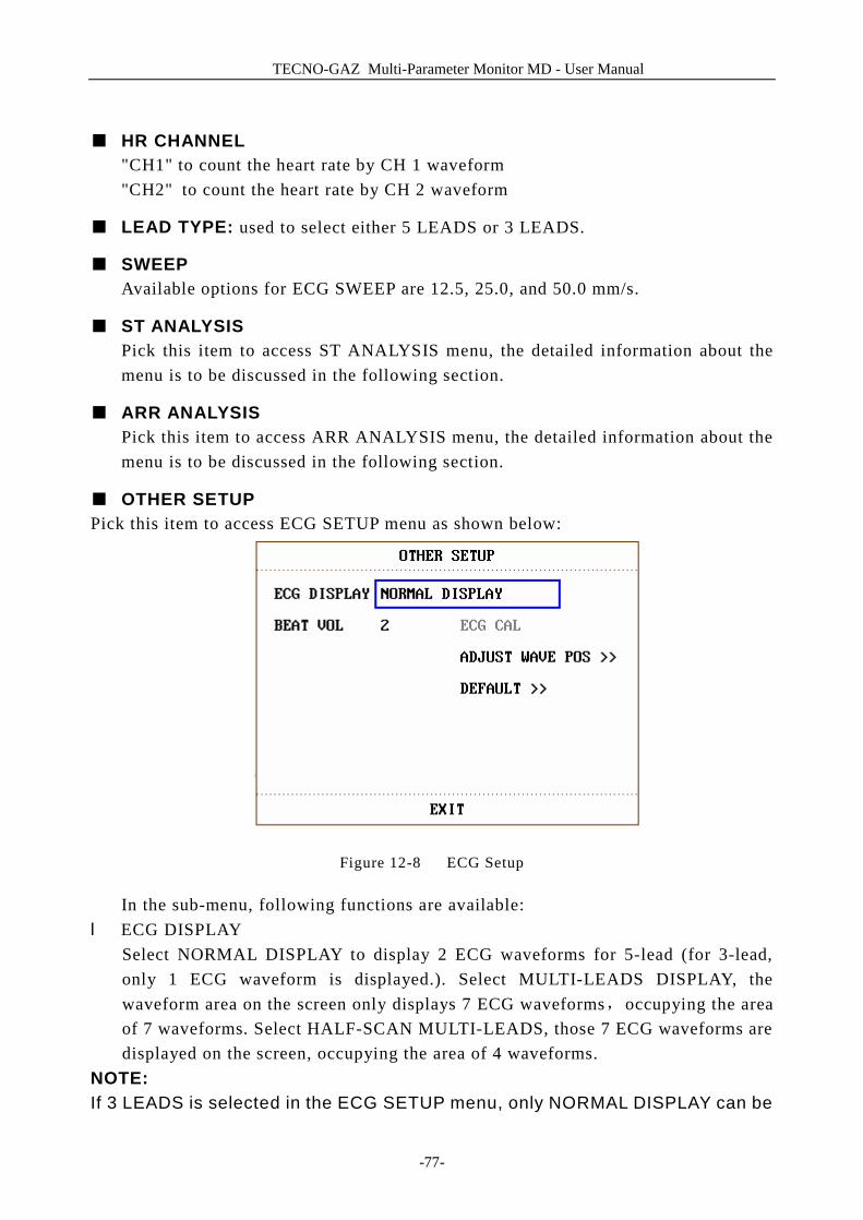
TECNO-GAZ Multi-Parameter Monitor MD - User Manual
-77-
■ HR CHANNEL
"CH1" to count the heart rate by CH 1 waveform "CH2" to count the heart rate by CH 2 waveform
■ LEAD TYPE: used to select either 5 LEADS or 3 LEADS.
■ SWEEP Available options for ECG SWEEP are 12.5, 25.0, and 50.0 mm/s.
■ ST ANALYSIS Pick this item to access ST ANALYSIS menu, the detailed information about the menu is to be discussed in the following section.
■ ARR ANALYSIS Pick this item to access ARR ANALYSIS menu, the detailed information about the menu is to be discussed in the following section.
■ OTHER SETUP Pick this item to access ECG SETUP menu as shown below:
Figure 12-8 ECG Setup
In the sub-menu, following functions are available: l ECG DISPLAY
Select NORMAL DISPLAY to display 2 ECG waveforms for 5-lead (for 3-lead, only 1 ECG waveform is displayed.). Select MULTI-LEADS DISPLAY, the waveform area on the screen only displays 7 ECG waveforms,occupying the area of 7 waveforms. Select HALF-SCAN MULTI-LEADS, those 7 ECG waveforms are displayed on the screen, occupying the area of 4 waveforms.
NOTE: If 3 LEADS is selected in the ECG SETUP menu, only NORMAL DISPLAY can be
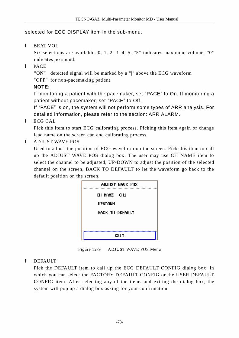
TECNO-GAZ Multi-Parameter Monitor MD - User Manual
-78-
selected for ECG DISPLAY item in the sub-menu. l BEAT VOL
Six selections are available: 0, 1, 2, 3, 4, 5. “5” indicates maximum volume. “0” indicates no sound.
l PACE "ON" detected signal will be marked by a "|" above the ECG waveform "OFF" for non-pacemaking patient. NOTE: If monitoring a patient with the pacemaker, set “PACE” to On. If monitoring a patient without pacemaker, set “PACE” to Off. If “PACE” is on, the system will not perform some types of ARR analysis. For detailed information, please refer to the section: ARR ALARM.
l ECG CAL Pick this item to start ECG calibrating process. Picking this item again or change lead name on the screen can end calibrating process.
l ADJUST WAVE POS Used to adjust the position of ECG waveform on the screen. Pick this item to call up the ADJUST WAVE POS dialog box. The user may use CH NAME item to select the channel to be adjusted, UP-DOWN to adjust the position of the selected channel on the screen, BACK TO DEFAULT to let the waveform go back to the default position on the screen.
Figure 12-9 ADJUST WAVE POS Menu
l DEFAULT Pick the DEFAULT item to call up the ECG DEFAULT CONFIG dialog box, in which you can select the FACTORY DEFAULT CONFIG or the USER DEFAULT CONFIG item. After selecting any of the items and exiting the dialog box, the system will pop up a dialog box asking for your confirmation.
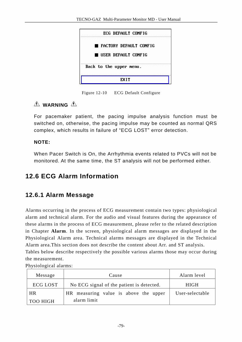
TECNO-GAZ Multi-Parameter Monitor MD - User Manual
-79-
Figure 12-10 ECG Default Configure
WARNING
For pacemaker patient, the pacing impulse analysis function must be switched on, otherwise, the pacing impulse may be counted as normal QRS complex, which results in failure of “ECG LOST” error detection.
NOTE:
When Pacer Switch is On, the Arrhythmia events related to PVCs will not be monitored. At the same time, the ST analysis will not be performed either.
12.6 ECG Alarm Information
12.6.1 Alarm Message
Alarms occurring in the process of ECG measurement contain two types: physiological alarm and technical alarm. For the audio and visual features during the appearance of these alarms in the process of ECG measurement, please refer to the related description in Chapter Alarm. In the screen, physiological alarm messages are displayed in the Physiological Alarm area. Technical alarms messages are displayed in the Technical Alarm area.This section does not describe the content about Arr. and ST analysis. Tables below describe respectively the possible various alarms those may occur during the measurement. Physiological alarms:
Message Cause Alarm level
ECG LOST No ECG signal of the patient is detected. HIGH
HR
TOO HIGH
HR measuring value is above the upper alarm limit
User-selectable
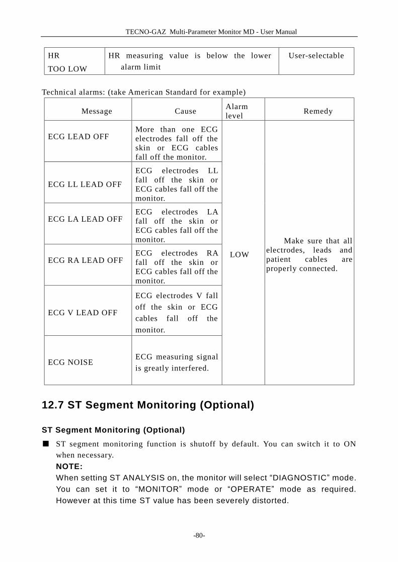
TECNO-GAZ Multi-Parameter Monitor MD - User Manual
-80-
HR
TOO LOW
HR measuring value is below the lower alarm limit
User-selectable
Technical alarms: (take American Standard for example)
Message Cause Alarm level Remedy
ECG LEAD OFF
More than one ECG electrodes fall off the skin or ECG cables fall off the monitor.
ECG LL LEAD OFF
ECG electrodes LL fall off the skin or ECG cables fall off the monitor.
ECG LA LEAD OFF
ECG electrodes LA fall off the skin or ECG cables fall off the monitor.
ECG RA LEAD OFF
ECG electrodes RA fall off the skin or ECG cables fall off the monitor.
ECG V LEAD OFF
ECG electrodes V fall off the skin or ECG cables fall off the monitor.
ECG NOISE ECG measuring signal is greatly interfered.
LOW
Make sure that all electrodes, leads and patient cables are properly connected.
12.7 ST Segment Monitoring (Optional)
ST Segment Monitoring (Optional) ■ ST segment monitoring function is shutoff by default. You can switch it to ON
when necessary. NOTE: When setting ST ANALYSIS on, the monitor will select “DIAGNOSTIC” mode. You can set it to “MONITOR” mode or “OPERATE” mode as required. However at this time ST value has been severely distorted.
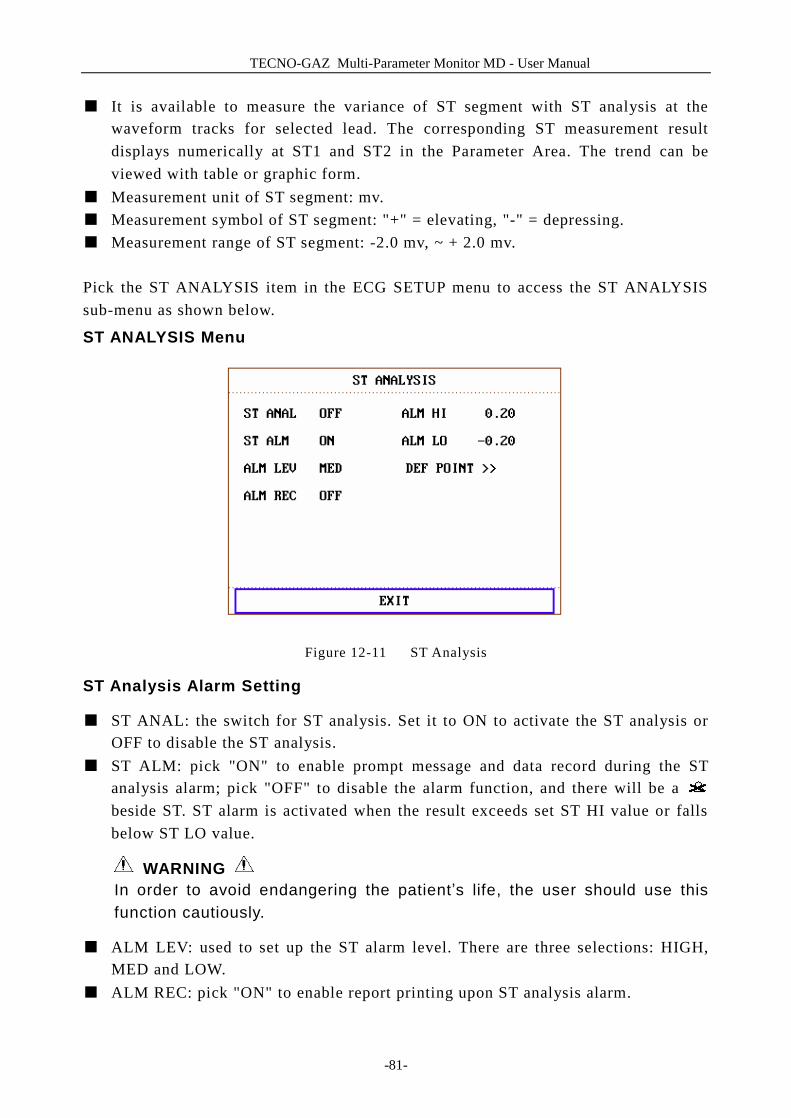
TECNO-GAZ Multi-Parameter Monitor MD - User Manual
-81-
■ It is available to measure the variance of ST segment with ST analysis at the waveform tracks for selected lead. The corresponding ST measurement result displays numerically at ST1 and ST2 in the Parameter Area. The trend can be viewed with table or graphic form.
■ Measurement unit of ST segment: mv. ■ Measurement symbol of ST segment: "+" = elevating, "-" = depressing. ■ Measurement range of ST segment: -2.0 mv, ~ + 2.0 mv. Pick the ST ANALYSIS item in the ECG SETUP menu to access the ST ANALYSIS sub-menu as shown below.
ST ANALYSIS Menu
Figure 12-11 ST Analysis
ST Analysis Alarm Setting
■ ST ANAL: the switch for ST analysis. Set it to ON to activate the ST analysis or OFF to disable the ST analysis.
■ ST ALM: pick "ON" to enable prompt message and data record during the ST analysis alarm; pick "OFF" to disable the alarm function, and there will be a beside ST. ST alarm is activated when the result exceeds set ST HI value or falls below ST LO value.
WARNING In order to avoid endangering the patient’s life, the user should use this function cautiously.
■ ALM LEV: used to set up the ST alarm level. There are three selections: HIGH, MED and LOW.
■ ALM REC: pick "ON" to enable report printing upon ST analysis alarm.
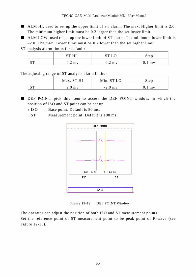
TECNO-GAZ Multi-Parameter Monitor MD - User Manual
-82-
■ ALM HI: used to set up the upper limit of ST alarm. The max. Higher limit is 2.0. The minimum higher limit must be 0.2 larger than the set lower limit.
■ ALM LOW: used to set up the lower limit of ST alarm. The minimum lower limit is –2.0. The max. Lower limit must be 0.2 lower than the set higher limit.
ST analysis alarm limits for default:
ST HI ST LO Step
ST 0.2 mv -0.2 mv 0.1 mv The adjusting range of ST analysis alarm limits:
Max. ST HI Min. ST LO Step
ST 2.0 mv -2.0 mv 0.1 mv ■ DEF POINT: pick this item to access the DEF POINT window, in which the
position of ISO and ST point can be set up. ¨ ISO Base point. Default is 80 ms. ¨ ST Measurement point. Default is 108 ms.
Figure 12-12 DEF POINT Window
The operator can adjust the position of both ISO and ST measurement points. Set the reference point of ST measurement point to be peak point of R-wave (see Figure 12-13).
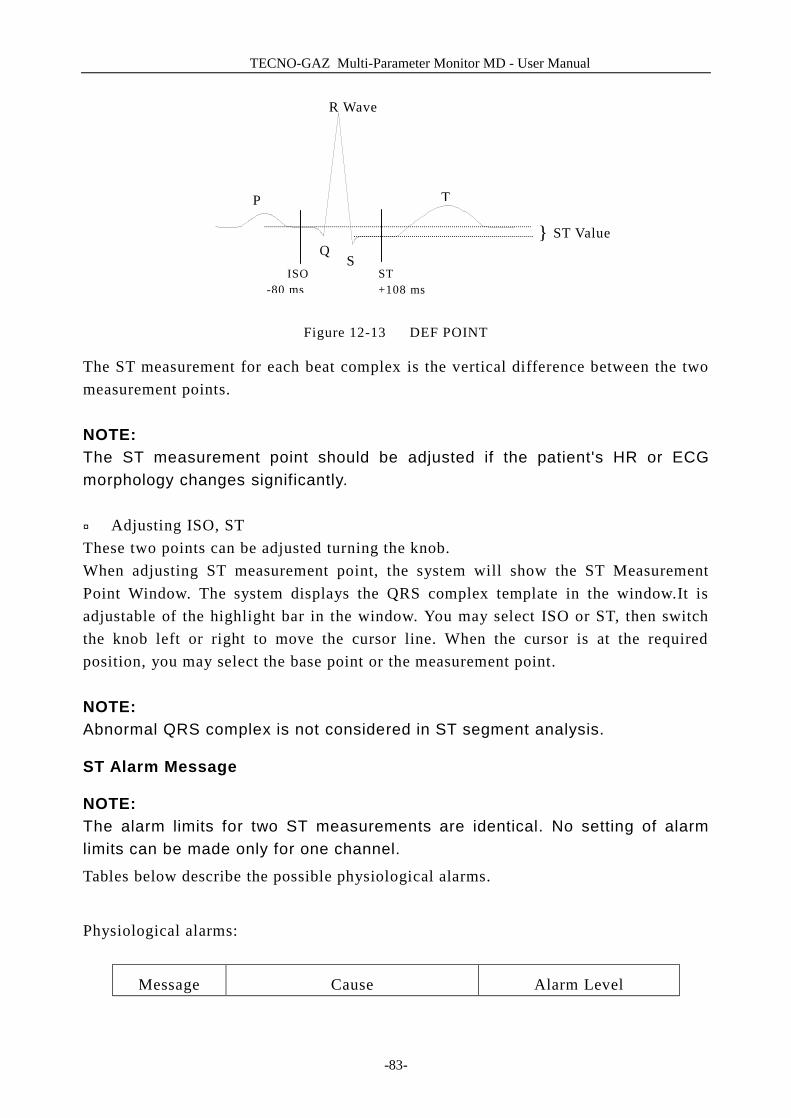
TECNO-GAZ Multi-Parameter Monitor MD - User Manual
-83-
Figure 12-13 DEF POINT
The ST measurement for each beat complex is the vertical difference between the two measurement points. NOTE: The ST measurement point should be adjusted if the patient's HR or ECG morphology changes significantly. ¨ Adjusting ISO, ST These two points can be adjusted turning the knob. When adjusting ST measurement point, the system will show the ST Measurement Point Window. The system displays the QRS complex template in the window.It is adjustable of the highlight bar in the window. You may select ISO or ST, then switch the knob left or right to move the cursor line. When the cursor is at the required position, you may select the base point or the measurement point. NOTE: Abnormal QRS complex is not considered in ST segment analysis.
ST Alarm Message
NOTE: The alarm limits for two ST measurements are identical. No setting of alarm limits can be made only for one channel.
Tables below describe the possible physiological alarms.
Physiological alarms:
Message Cause Alarm Level
Q }
R Wave
P
S
T
ST Value
ISO -80 ms
ST +108 ms
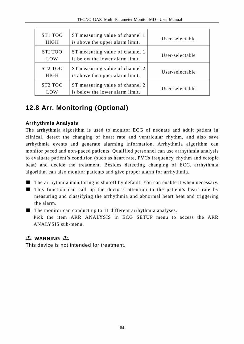
TECNO-GAZ Multi-Parameter Monitor MD - User Manual
-84-
ST1 TOO HIGH
ST measuring value of channel 1 is above the upper alarm limit.
User-selectable
STI TOO LOW
ST measuring value of channel 1 is below the lower alarm limit.
User-selectable
ST2 TOO HIGH
ST measuring value of channel 2 is above the upper alarm limit.
User-selectable
ST2 TOO LOW
ST measuring value of channel 2 is below the lower alarm limit.
User-selectable
12.8 Arr. Monitoring (Optional)
Arrhythmia Analysis The arrhythmia algorithm is used to monitor ECG of neonate and adult patient in clinical, detect the changing of heart rate and ventricular rhythm, and also save arrhythmia events and generate alarming information. Arrhythmia algorithm can monitor paced and non-paced patients. Qualified personnel can use arrhythmia analysis to evaluate patient’s condition (such as heart rate, PVCs frequency, rhythm and ectopic beat) and decide the treatment. Besides detecting changing of ECG, arrhythmia algorithm can also monitor patients and give proper alarm for arrhythmia.
■ The arrhythmia monitoring is shutoff by default. You can enable it when necessary. ■ This function can call up the doctor's attention to the patient's heart rate by
measuring and classifying the arrhythmia and abnormal heart beat and triggering the alarm.
■ The monitor can conduct up to 11 different arrhythmia analyses. Pick the item ARR ANALYSIS in ECG SETUP menu to access the ARR ANALYSIS sub-menu.
WARNING This device is not intended for treatment.

TECNO-GAZ Multi-Parameter Monitor MD - User Manual
-85-
ARR ANALYSIS Menu
Figure 12-14 ARR Analysis
■ ARR ANAL: Pick "ON" during monitoring. Default set is "OFF". ■ PVCs ALM: Pick "ON" to enable prompt message when alarm occurs; pick "OFF"
to disable the alarm function, and there will be a beside “PVCs”.
WARNING In order to avoid endangering the patient’s life, the user should use this function cautiously.
■ ALM LEV: Selectable from HIGH, MED, LOW. Level HIGH represents the most serious case.
■ ALM REC: pick "ON" to enable report printing upon PVCs alarm. ■ PVCs alarm is activated when the PVCs exceeds set PVCs ALM HI value. PVCs alarm upper limits:
Max Min Step
PVCs 10 1 1
PVCs Alarm and Prompt Message: Tables below describe the possible physiological alarms occurring during pvcs measurement.
Physiological alarms:
Message Cause Alarm Level
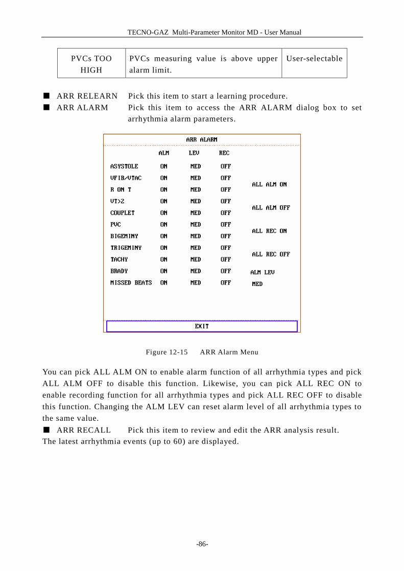
TECNO-GAZ Multi-Parameter Monitor MD - User Manual
-86-
PVCs TOO HIGH
PVCs measuring value is above upper alarm limit.
User-selectable
■ ARR RELEARN Pick this item to start a learning procedure. ■ ARR ALARM Pick this item to access the ARR ALARM dialog box to set
arrhythmia alarm parameters.
Figure 12-15 ARR Alarm Menu
You can pick ALL ALM ON to enable alarm function of all arrhythmia types and pick ALL ALM OFF to disable this function. Likewise, you can pick ALL REC ON to enable recording function for all arrhythmia types and pick ALL REC OFF to disable this function. Changing the ALM LEV can reset alarm level of all arrhythmia types to the same value. ■ ARR RECALL Pick this item to review and edit the ARR analysis result. The latest arrhythmia events (up to 60) are displayed.
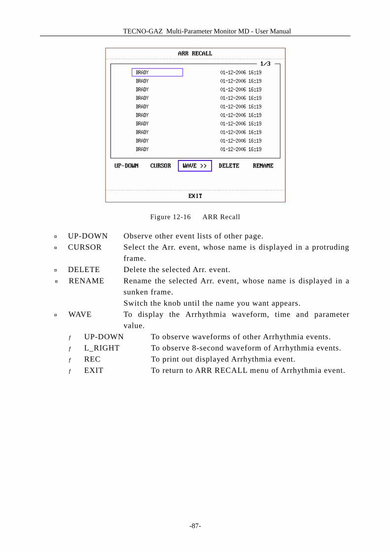
TECNO-GAZ Multi-Parameter Monitor MD - User Manual
-87-
Figure 12-16 ARR Recall
¨ UP-DOWN Observe other event lists of other page. ¨ CURSOR Select the Arr. event, whose name is displayed in a protruding
frame. ¨ DELETE Delete the selected Arr. event. ¨ RENAME Rename the selected Arr. event, whose name is displayed in a
sunken frame. Switch the knob until the name you want appears.
¨ WAVE To display the Arrhythmia waveform, time and parameter value.
¦ UP-DOWN To observe waveforms of other Arrhythmia events. ¦ L_RIGHT To observe 8-second waveform of Arrhythmia events. ¦ REC To print out displayed Arrhythmia event. ¦ EXIT To return to ARR RECALL menu of Arrhythmia event.
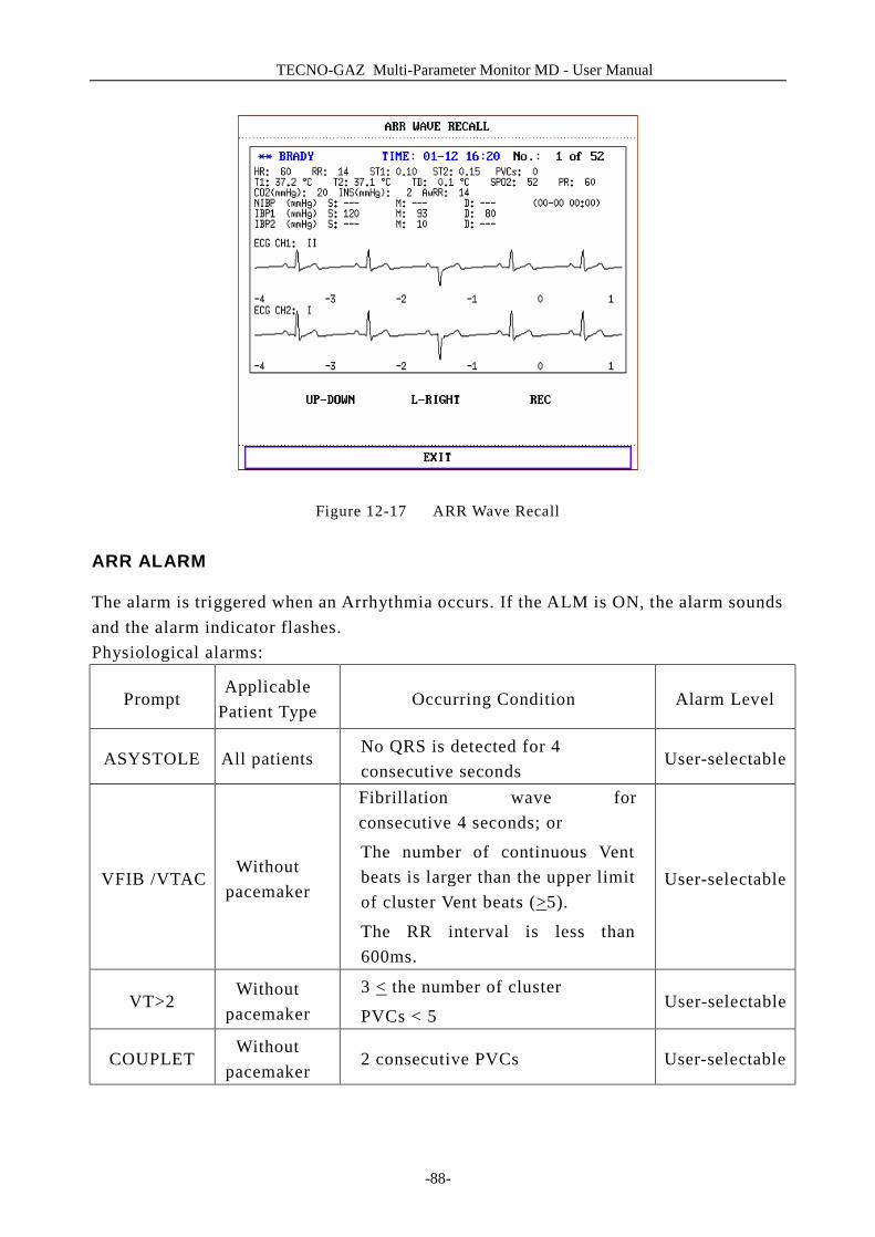
TECNO-GAZ Multi-Parameter Monitor MD - User Manual
-88-
Figure 12-17 ARR Wave Recall
ARR ALARM
The alarm is triggered when an Arrhythmia occurs. If the ALM is ON, the alarm sounds and the alarm indicator flashes. Physiological alarms:
Prompt Applicable
Patient Type Occurring Condition Alarm Level
ASYSTOLE All patients No QRS is detected for 4 consecutive seconds
User-selectable
VFIB /VTAC Without
pacemaker
Fibrillation wave for consecutive 4 seconds; or
The number of continuous Vent beats is larger than the upper limit of cluster Vent beats (>5).
The RR interval is less than 600ms.
User-selectable
VT>2 Without
pacemaker 3 < the number of cluster
PVCs < 5 User-selectable
COUPLET Without
pacemaker 2 consecutive PVCs User-selectable
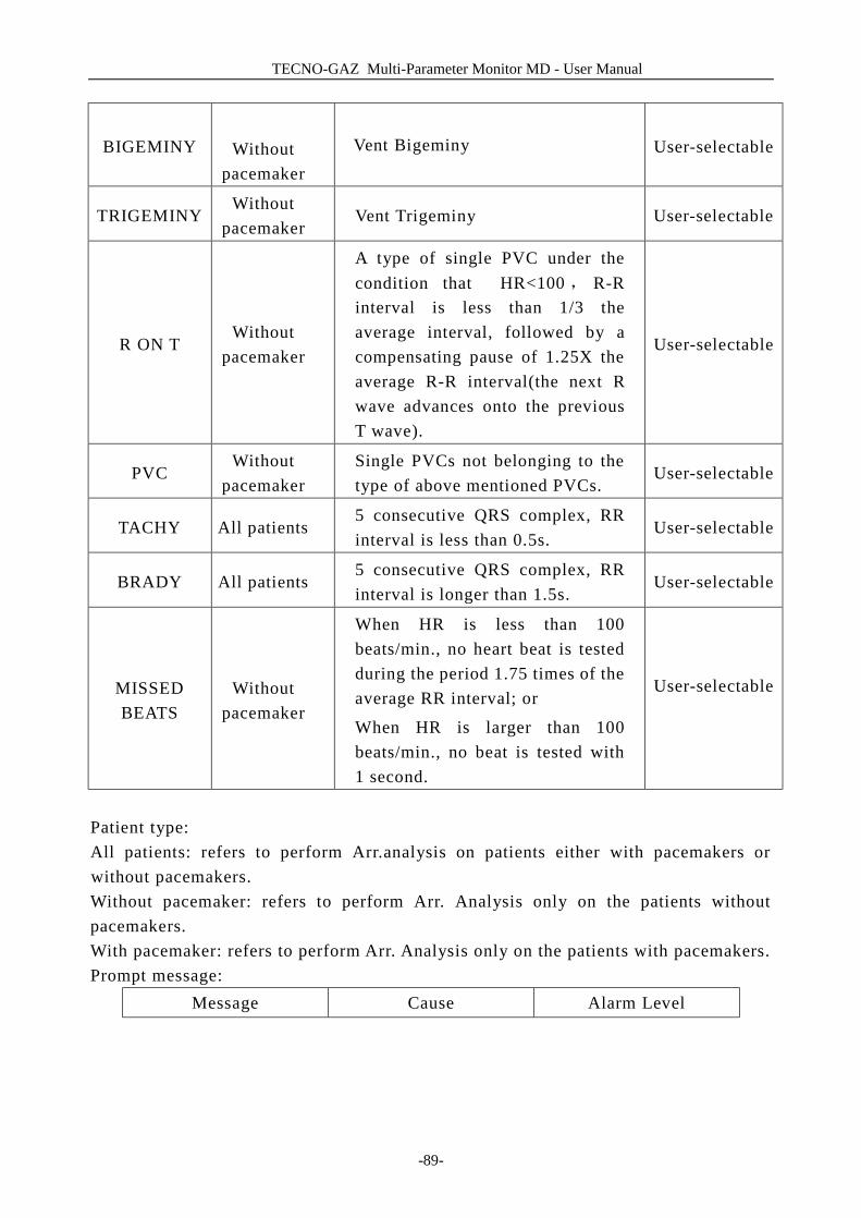
TECNO-GAZ Multi-Parameter Monitor MD - User Manual
-89-
BIGEMINY
Without pacemaker
Vent Bigeminy User-selectable
TRIGEMINY Without
pacemaker Vent Trigeminy User-selectable
R ON T Without
pacemaker
A type of single PVC under the condition that HR<100 , R-R interval is less than 1/3 the average interval, followed by a compensating pause of 1.25X the average R-R interval(the next R wave advances onto the previous T wave).
User-selectable
PVC Without
pacemaker Single PVCs not belonging to the type of above mentioned PVCs.
User-selectable
TACHY All patients 5 consecutive QRS complex, RR interval is less than 0.5s.
User-selectable
BRADY All patients 5 consecutive QRS complex, RR interval is longer than 1.5s.
User-selectable
MISSED BEATS
Without pacemaker
When HR is less than 100 beats/min., no heart beat is tested during the period 1.75 times of the average RR interval; or
When HR is larger than 100 beats/min., no beat is tested with 1 second.
User-selectable
Patient type: All patients: refers to perform Arr.analysis on patients either with pacemakers or without pacemakers. Without pacemaker: refers to perform Arr. Analysis only on the patients without pacemakers. With pacemaker: refers to perform Arr. Analysis only on the patients with pacemakers. Prompt message:
Message Cause Alarm Level
TECNO-GAZ Multi-Parameter Monitor MD - User Manual
-90-
ARR LEARNING
The QRS template building required for Arr. Analysis is in process.
No alarm
NOTE: Arrhythmia name displays in the Alarm Message Area.
12.9 Measuring RESP
12.9.1 How to Measure RESP?
The monitor measures respiration from the amount of thoracic impedance between two ECG electrodes. The change of impedance between the two electrodes, (due to the thoracic movement), produces a respiratory waveform on the screen.
12.9.2 Setting Up RESP Measurement
For RESP monitoring, it is not necessary for additional electrodes, however, it is very important to attach the electrodes to the correct positions. Some patients, due to their clinical condition, expand their chest laterally, causing a negative intrathoracic pressure. In these cases it is better to place the two RESP electrodes laterally in the right axillary and left lateral chest areas at the maximum point of breathing movement to optimize the respiratory waveform.
NOTE: The RESP monitoring is not recommended to be used on patients who are very active, as this can cause false alarms. Checklist for RESP Monitoring 1. Prepare the patient's skin prior to placing the electrodes. 2. Attach snap or clip to the electrodes and attach the electrodes to the patient as
described below. 3. Switch on the monitor.
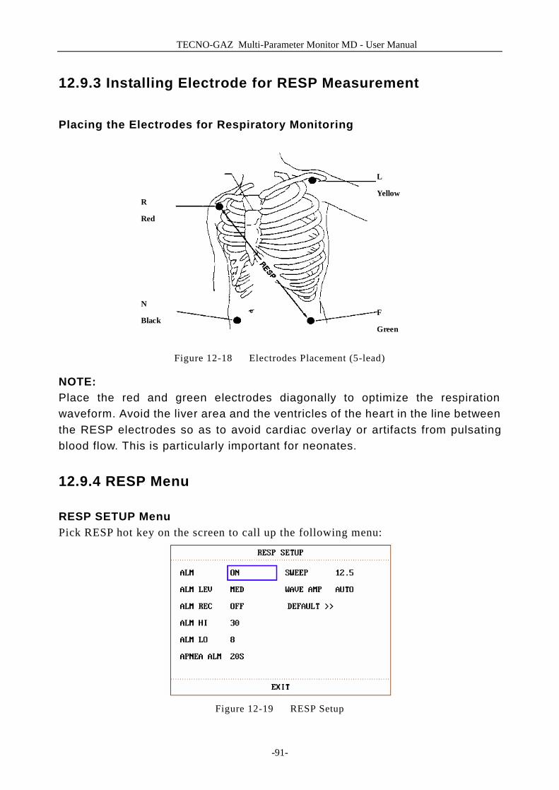
TECNO-GAZ Multi-Parameter Monitor MD - User Manual
-91-
12.9.3 Installing Electrode for RESP Measurement
Placing the Electrodes for Respiratory Monitoring
R
Red
N
BlackF
Green
L
Yellow
Figure 12-18 Electrodes Placement (5-lead)
NOTE: Place the red and green electrodes diagonally to optimize the respiration waveform. Avoid the liver area and the ventricles of the heart in the line between the RESP electrodes so as to avoid cardiac overlay or artifacts from pulsating blood flow. This is particularly important for neonates.
12.9.4 RESP Menu
RESP SETUP Menu Pick RESP hot key on the screen to call up the following menu:
Figure 12-19 RESP Setup
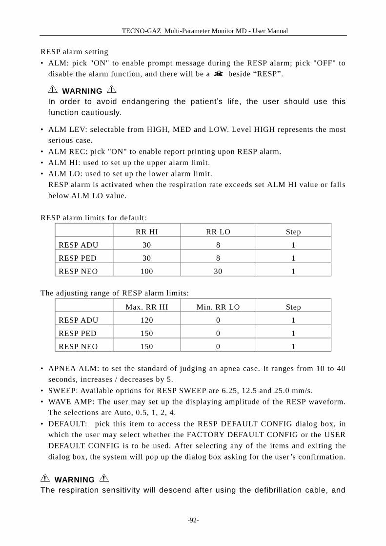
TECNO-GAZ Multi-Parameter Monitor MD - User Manual
-92-
RESP alarm setting • ALM: pick "ON" to enable prompt message during the RESP alarm; pick "OFF" to
disable the alarm function, and there will be a beside “RESP”.
WARNING In order to avoid endangering the patient’s life, the user should use this function cautiously.
• ALM LEV: selectable from HIGH, MED and LOW. Level HIGH represents the most serious case.
• ALM REC: pick "ON" to enable report printing upon RESP alarm. • ALM HI: used to set up the upper alarm limit. • ALM LO: used to set up the lower alarm limit.
RESP alarm is activated when the respiration rate exceeds set ALM HI value or falls below ALM LO value.
RESP alarm limits for default:
RR HI RR LO Step
RESP ADU 30 8 1
RESP PED 30 8 1
RESP NEO 100 30 1 The adjusting range of RESP alarm limits:
Max. RR HI Min. RR LO Step
RESP ADU 120 0 1
RESP PED 150 0 1
RESP NEO 150 0 1 • APNEA ALM: to set the standard of judging an apnea case. It ranges from 10 to 40
seconds, increases / decreases by 5. • SWEEP: Available options for RESP SWEEP are 6.25, 12.5 and 25.0 mm/s. • WAVE AMP: The user may set up the displaying amplitude of the RESP waveform.
The selections are Auto, 0.5, 1, 2, 4. • DEFAULT: pick this item to access the RESP DEFAULT CONFIG dialog box, in
which the user may select whether the FACTORY DEFAULT CONFIG or the USER DEFAULT CONFIG is to be used. After selecting any of the items and exiting the dialog box, the system will pop up the dialog box asking for the user ’s confirmation.
WARNING
The respiration sensitivity will descend after using the defibrillation cable, and
TECNO-GAZ Multi-Parameter Monitor MD - User Manual
-93-
the “4” mode is recommended in the WAVE AMP.
12.9.5 RESP Alarm Message
Tables below describe the possible physiological alarms messages occurring during resp measurement.
Physiological alarms:
Message Cause Alarm Level
RR TOO HIGH
RESP measuring value is above upper alarm limit.
User-selectable
RR TOO LOW
RESP measuring value is below lower alarm limit.
User-selectable
RESP APNEA
RESP can not be measured within specific time interval.
HIGH
12.10 Maintenance and Cleaning
Care and Cleaning
WARNING Before cleaning the monitor or the sensor, make sure that the equipment is switched off and disconnected from the power line. If there is any sign that the ECG cable may be damaged or deteriorated, replace it with a new one instead of continuing its application on the patient. ■ Cleaning:
Use fine-hair cloth moistened in mild soap liquid or cleaning agent containing 70% ethanol to clean the equipment.
■ Sterilization To avoid extended damage to the equipment, sterilization is only recommended when stipulated as necessary in the Hospital Maintenance Schedule. Sterilization facilities should be cleaned first. Recommended sterilization material: ü Ethylate: 70% alcohol, 70% isopropanol ü Acetaldehyde
TECNO-GAZ Multi-Parameter Monitor MD - User Manual
-94-
■ Disinfection
To avoid extended damage to the equipment, disinfection is only recommended when stipulated as necessary in the Hospital Maintenance Schedule. Disinfection facilities should be cleaned first.

TECNO-GAZ Multi-Parameter Monitor MD - User Manual
-95-
13 SpO2 Monitoring
13.1 What is SpO2 Monitoring
SpO2 Plethysmogram measurement is employed to determine the oxygen saturation of hemoglobin in the arterial blood. If, for example, 97% hemoglobin molecules in the red blood cells of the arterial blood combine with oxygen, then the blood has a SpO2 oxygen saturation of 97%. The SpO2 numeric on the monitor will read 97% .The SpO2 numeric shows the percentage of hemoglobin molecules which have combined with oxygen molecules to form oxyhemoglobin. The SpO2/PLETH parameter can also provide a pulse rate signal and a plethysmogram wave.
How the SpO2 / PLETH Parameter Works
■ Arterial oxygen saturation is measured by a method called pulse oximetry. It is a continuous, non-invasive method based on the different absorption spectra of reduced hemoglobin and oxyhemoglobin. It measures how much light, sent from light sources on one side of the sensor, is transmitted through patient tissue (such as a finger or an ear), to a receiver on the other side.
■ The amount of light transmitted depends on many factors, most of which are constant. However, one of these factors, the blood flow in the arteries, varies with time, because it is pulsating. By measuring the light absorption during a pulsation, it is possible to derive the oxygen saturation of the arterial blood. Detecting the pulsation gives a PLETH waveform and pulse rate signal.
■ The SpO2 value and the PLETH waveform can be displayed on the main interface.
WARNING Pulse oximetry can overestimate the SpO2 value in the presence of Hb-CO, Met-Hb or dye dilution chemicals. SpO2 / Pulse Monitoring
WARNING ES (Electrosurgery) equipment wire and SpO2 cable must not be tangled up.
TECNO-GAZ Multi-Parameter Monitor MD - User Manualanual
-96-
WARNING Do not put the sensor on extremities with arterial catheter or venous syringe. NOTE: Do not perform SpO2 measuring and NIBP measuring in same arm at one time, because obstruction of blood flow during NIBP measuring may adversely affect the reading of SpO2 value.
13.2 Precautions during SpO2/Pulse Monitoring
NOTE: l Make sure the nail covers the light window; l The wire should be on the backside of the hand. NOTE:
SpO2 value always displays at the same position. Pulse Rate will display when HR FROM is set at "SPO2", No ECG signal when HR FROM is set at “Auto”.
NOTE:
SpO2 waveform is not proportional to the pulse volume.
WARNING
Verify sensor cable fault detection before beginning of monitoring phase. Unplug the SpO2 sensor cable from the socket, the screen will display the error message “SpO2 SENSOR OFF” and the audible alarm is activated.
WARNING
If the SpO2 sensor can’t work properly, please reconnect the sensor or change a new one.
WARNING
Do not use the sterile supplied SpO2 sensors if the packaging or the sensor is damaged and return them to the vendor.
WARNING
Prolonged and continuous monitoring may increase jeopardy of unexpected change of dermal condition such as abnormal sensitivity, rubescence, vesicle, repressive putrescence, and so on. It is especially important to check the sensor
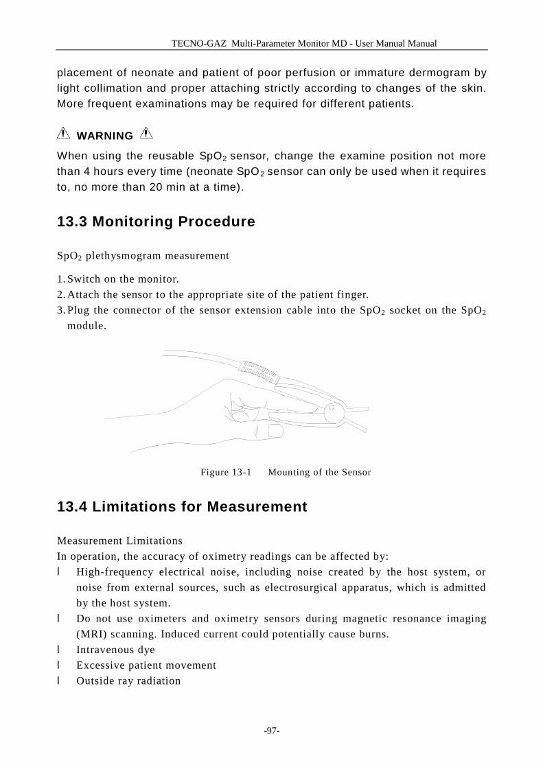
TECNO-GAZ Multi-Parameter Monitor MD - User Manual Manual
-97-
placement of neonate and patient of poor perfusion or immature dermogram by light collimation and proper attaching strictly according to changes of the skin. More frequent examinations may be required for different patients.
WARNING
When using the reusable SpO2 sensor, change the examine position not more than 4 hours every time (neonate SpO2 sensor can only be used when it requires to, no more than 20 min at a time).
13.3 Monitoring Procedure
SpO2 plethysmogram measurement
1. Switch on the monitor. 2. Attach the sensor to the appropriate site of the patient finger. 3. Plug the connector of the sensor extension cable into the SpO2 socket on the SpO2
module.
Figure 13-1 Mounting of the Sensor
13.4 Limitations for Measurement
Measurement Limitations In operation, the accuracy of oximetry readings can be affected by: l High-frequency electrical noise, including noise created by the host system, or
noise from external sources, such as electrosurgical apparatus, which is admitted by the host system.
l Do not use oximeters and oximetry sensors during magnetic resonance imaging (MRI) scanning. Induced current could potentially cause burns.
l Intravenous dye l Excessive patient movement l Outside ray radiation
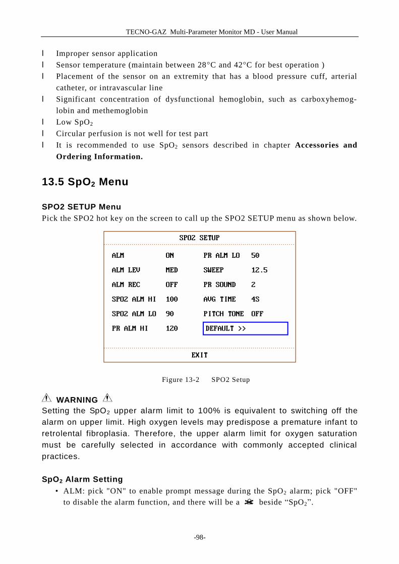
TECNO-GAZ Multi-Parameter Monitor MD - User Manual
-98-
l Improper sensor application l Sensor temperature (maintain between 28°C and 42°C for best operation ) l Placement of the sensor on an extremity that has a blood pressure cuff, arterial
catheter, or intravascular line l Significant concentration of dysfunctional hemoglobin, such as carboxyhemog-
lobin and methemoglobin l Low SpO2 l Circular perfusion is not well for test part l It is recommended to use SpO2 sensors described in chapter Accessories and
Ordering Information.
13.5 SpO2 Menu
SPO2 SETUP Menu Pick the SPO2 hot key on the screen to call up the SPO2 SETUP menu as shown below.
Figure 13-2 SPO2 Setup
WARNING Setting the SpO2 upper alarm limit to 100% is equivalent to switching off the alarm on upper limit. High oxygen levels may predispose a premature infant to retrolental fibroplasia. Therefore, the upper alarm limit for oxygen saturation must be carefully selected in accordance with commonly accepted clinical practices. SpO2 Alarm Setting
• ALM: pick "ON" to enable prompt message during the SpO2 alarm; pick "OFF" to disable the alarm function, and there will be a beside “SpO2”.

TECNO-GAZ Multi-Parameter Monitor MD - User Manual
-99-
WARNING In order to avoid endangering the patient’s life, the user should use this function cautiously.
• ALM LEV: used to set up alarm level, selectable from HIGH, MED and LOW. HIGH represents the most serious case.
• ALM REC: pick "ON" to enable report printing upon SpO2 alarm. • SpO2 alarm is activated when the result exceeds set SPO2 ALM HI value or falls
below SPO2 ALM LO value. Use the knob to pick the SPO2 ALM HI or SPO2 ALM LOW item and turn the knob to select the desired alarm limit.
• PR alarm is activated when the pulse rate exceeds set PR ALM HI value or falls below PR ALM LO value. Use the knob to pick the PR ALM HI or PR ALM LOW item and turn the knob to select the desired alarm limit.
The adjusting range of SpO2 alarm limits is: 0~100 SpO2 alarm limits for default:
Max. Upper Limit Min. Lower Limit Step
ADU 100 90 1
PED 100 90 1
NEO 95 80 1 The adjusting range of PR alarm limits is: 0~254
PR alarm limits for default:
Max. Upper Limit Min. Lower Limit Step
ADU 120 50 1
PED 160 75 1
NEO 200 100 1 ■ SWEEP
Available options for SPO2 SWEEP are 6.25, 12.5 and 25.0 mm/s. ■ PR SOUND
Pulse beep volume. Options are “0~5”. ■ AVG TIME
4S, 8S, 16S represent times that SpO2 average value is counted. ■ PITCH TONE
When ON is enabled, the system will provide prompt sound with different tone for clinic under complex monitoring environment, basing on the variance of SpO2 value.
■ DEFAULT
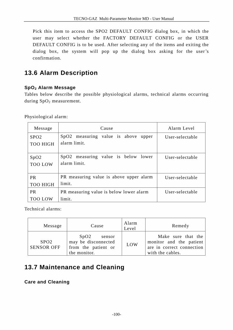
TECNO-GAZ Multi-Parameter Monitor MD - User Manual
-100-
Pick this item to access the SPO2 DEFAULT CONFIG dialog box, in which the user may select whether the FACTORY DEFAULT CONFIG or the USER DEFAULT CONFIG is to be used. After selecting any of the items and exiting the dialog box, the system will pop up the dialog box asking for the user ’s confirmation.
13.6 Alarm Description
SpO2 Alarm Message Tables below describe the possible physiological alarms, technical alarms occurring during SpO2 measurement.
Physiological alarm:
Message Cause Alarm Level
SPO2 TOO HIGH
SpO2 measuring value is above upper alarm limit.
User-selectable
SpO2 TOO LOW
SpO2 measuring value is below lower alarm limit.
User-selectable
PR TOO HIGH
PR measuring value is above upper alarm limit.
User-selectable
PR TOO LOW
PR measuring value is below lower alarm limit.
User-selectable
Technical alarms:
Message Cause Alarm Level Remedy
SPO2 SENSOR OFF
SpO2 sensor may be disconnected from the patient or the monitor.
LOW
Make sure that the monitor and the patient are in correct connection with the cables.
13.7 Maintenance and Cleaning
Care and Cleaning
TECNO-GAZ Multi-Parameter Monitor MD - User Manual
-101-
WARNING Before cleaning the monitor or the sensor, make sure that the equipment is switched off and disconnected from the power line.
WARNING Do not subject the sensor to autoclaving. Do not immerse the sensor into any liquid. Do not use any sensor or cable that may be damaged or deteriorated. For cleaning:
n Use a cotton ball or a soft mull moistened with hospital-grade ethanol to wipe the surface of the sensor, and then dry it with a cloth. This cleaning method can also be applied to the luminotron and receiving unit.
n The cable can be cleaned with 3% hydrogen dioxide, 7% isopropanol, or other active reagent. However, connector of the sensor shall not be subjected to such solution.
TECNO-GAZ Multi-Parameter Monitor MD - User Manual
-102-
14 NIBP Monitoring
14.1 Introduction
■ The Non-invasive Blood Pressure (NIBP) module measures the blood pressure using the oscillometric method.
■ It is applicable for adult, pediatric, and neonatal usage. ■ There are two modes of measurement available: manual, automatic. Each mode
displays the diastolic, systolic and mean blood pressure. ² In the MANUAL mode, only one measurement is conducted for each time. ² In the AUTO mode, the measurement is cycled; you can set the interval time to
1/2/3/4/5/10/15/30/60/90/120/180/240/480 minutes. ² In the CONTINUAL mode, the system executes NIBP measurement continuously
within five minutes.
WARNING 1. You must not perform NIBP measurements on patients with sickle-cell disease
or under any condition which the skin is damaged or expected to be damaged. 2. For a thrombasthemia patient, it is important to determine whether
measurement of the blood pressure shall be done automatically. The determination should be based on the clinical evaluation.
3. Ensure that the correct setting is selected when performing measurements on children. It may be dangerous for the children to use an over pressure level.
NOTE: The equipment is suitable for use in the presence of electrosurgery. NOTE: The equipment can provide protective means to prevent the patient from being burned when used with HF SURGICAL EQUIPMENT. NOTE: The equipment can protect against the effects of the discharge of a defibrillator. NOTE: The equipment is suitable for connection to public mains as defined in CISPR 11.
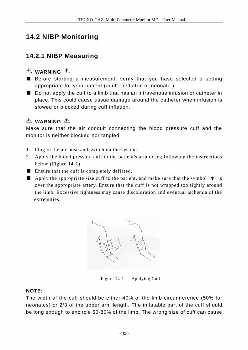
TECNO-GAZ Multi-Parameter Monitor MD - User Manual
-103-
14.2 NIBP Monitoring
14.2.1 NIBP Measuring
WARNING ■ Before starting a measurement, verify that you have selected a setting
appropriate for your patient (adult, pediatric or neonate.) ■ Do not apply the cuff to a limb that has an intravenous infusion or catheter in
place. This could cause tissue damage around the catheter when infusion is slowed or blocked during cuff inflation.
WARNING
Make sure that the air conduit connecting the blood pressure cuff and the monitor is neither blocked nor tangled. 1. Plug in the air hose and switch on the system. 2. Apply the blood pressure cuff to the patient's arm or leg following the instructions
below (Figure 14-1). ■ Ensure that the cuff is completely deflated. ■ Apply the appropriate size cuff to the patient, and make sure that the symbol "Φ" is
over the appropriate artery. Ensure that the cuff is not wrapped too tightly around the limb. Excessive tightness may cause discoloration and eventual ischemia of the extremities.
Figure 14-1 Applying Cuff
NOTE: The width of the cuff should be either 40% of the limb circumference (50% for neonates) or 2/3 of the upper arm length. The inflatable part of the cuff should be long enough to encircle 50-80% of the limb. The wrong size of cuff can cause

TECNO-GAZ Multi-Parameter Monitor MD - User Manual
-104-
erroneous readings. If the cuff size is in question, then use a larger cuff.
Size of reusable cuff for neonate/children/adult
Patient Type Limb perimeter Cuff width Hose
Infant 10 ~19 cm 8 cm
Child 18 ~ 26 cm 10.6 cm
Adult 25 ~ 35 cm 14 cm
Large Adult 33 ~ 47 cm 17 cm
Thigh 46 ~ 66 cm 21 cm
1.5 m or 3 m
Size of disposable cuff for neonate/children/adult
Size No. Limb perimeter Cuff width Hose
1 3.1 ~ 5.7 cm 2.5 cm
2 4.3 ~ 8.0 cm 3.2 cm
3 5.8 ~ 10.9 cm 4.3 cm
4 7.1 ~ 13.1 cm 5.1 cm
1.5 m or 3 m
The lifecycle of cuff is: 480mmHg/20000 times; 300mmHg/50000 times. ■ Make sure that the cuff edge falls within the range of mark <->. If it does not, use a
larger or smaller cuff that fits better.
3. Connect the cuff to the air hose. The limb chosen for taking the measurement should be placed at the same level as the patient's heart. If this is not possible you should apply the following corrections to the measured values:
■ If the cuff is placed higher than the heart level, add 0.75 mmHg (0.10 kPa) for each inch of difference.
■ If it is placed lower than the heart level, deduct 0.75 mmHg (0.10 kPa) for each inch of difference.
4. Check whether the patient mode is appropriately selected. Access PATIENT SETUP menu from SYSTEM MENU and pick PAT TYPE item and turn the knob to select the required patient type.
5. Select a measurement mode in the NIBP SETUP menu. Refer to the following paragraphs Operation Hints for details.
6. Press the START button on the front panel to start a measurement.
TECNO-GAZ Multi-Parameter Monitor MD - User Manual
-105-
Operation Hints
1. To start auto measuring: Access NIBP SETUP menu and pick the INTERVAL item, in which the user may choose the selections other than MANUAL to set up the time interval for auto
measurement. After that, press START button on the front panel to start the auto measuring according to the selected time interval.
WARNING
Prolonged non-invasive blood pressure measurements in Auto mode may be associated with purport, ischemia and neuropathy in the limb wearing the cuff. When monitoring a patient, examine the extremities of the limb frequently for normal color, warmth and sensitivity. If any abnormality is observed, stop the blood pressure measurements.
2. To stop auto measuring:
During auto measuring, press START button on the front panel at any time to stop auto measurement.
3. To start a manual measuring: n Access NIBP SETUP menu and pick the INTERVAL item. Select the MANUAL
selection. Then press the START button on the front panel to start a manual measurement.
n During the idle period of auto measuring process, press the START button on the front panel at any time to start a manual measurement. Then press the
START button on the front panel to stop manual measurement and the system continues executes auto-measuring program according to selected time interval.
4. To start a manual measuring during the AUTO mode:
Press START button on the front panel.
5. To stop a manual measuring
Repress the START button on the front panel again.
TECNO-GAZ Multi-Parameter Monitor MD - User Manual
-106-
WARNING Prolonged non-invasive blood pressure measurements in Auto mode may be associated with purport, ischemia and neuropathy in the limb wearing the cuff. When monitoring a patient, examine the extremities of the limb frequently for normal color, warmth and sensitivity. If any abnormality is observed, stop the blood pressure measurements.
6. To start a continuous measuring: Access the NIBP SETUP menu and pick the CONTINUAL item to start a continuous measurement. The continuous measurement will last 5 minutes.
7. To stop continuous measuring:
During continuous measuring press START button on the front panel at any time to stop continuous measurement.
NOTE: If you are in doubt about the accuracy of any reading(s), check the patient's vital signs by an alternative method before checking the functioning of the monitor.
WARNING If liquid is inadvertently splashed on the equipment or its accessories, or may enter the conduit or inside the monitor, contact local Customer Service Center.
Measurement Limitations
To different patient conditions, the oscillometric measurement has certain limitations. The measurement is in search of regular arterial pressure pulse. In those circumstances when the patient's condition makes it difficult to detect, the measurement becomes unreliable and measuring time increases. The user should be aware that the following conditions could interfere with the measurement, making the measurement unreliable or longer to derive. In some cases, the patient's condition will make a measurement impossible.
l Patient Movement Measurements will be unreliable or may not be possible if the patient is moving, shivering or having convulsions. These motions may interfere with the detection of the arterial pressure pulses. In addition, the measurement time will be prolonged.
l Cardiac Arrhythmia's Measurements will be unreliable and may not be possible if the patient's cardiac arrhythmia has caused an irregular heartbeat. The measuring time thus will be prolonged.
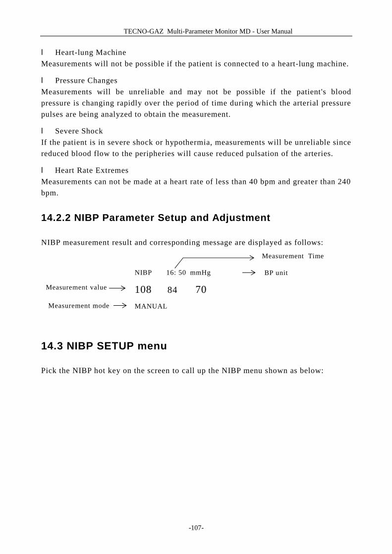
TECNO-GAZ Multi-Parameter Monitor MD - User Manual
-107-
l Heart-lung Machine Measurements will not be possible if the patient is connected to a heart-lung machine.
l Pressure Changes Measurements will be unreliable and may not be possible if the patient's blood pressure is changing rapidly over the period of time during which the arterial pressure pulses are being analyzed to obtain the measurement.
l Severe Shock If the patient is in severe shock or hypothermia, measurements will be unreliable since reduced blood flow to the peripheries will cause reduced pulsation of the arteries.
l Heart Rate Extremes Measurements can not be made at a heart rate of less than 40 bpm and greater than 240 bpm.
14.2.2 NIBP Parameter Setup and Adjustment
NIBP measurement result and corresponding message are displayed as follows:
14.3 NIBP SETUP menu
Pick the NIBP hot key on the screen to call up the NIBP menu shown as below:
NIBP 16: 50 mmHg
108 84 70 MANUAL
Measurement Time
BP unit
Measurement mode
Measurement value
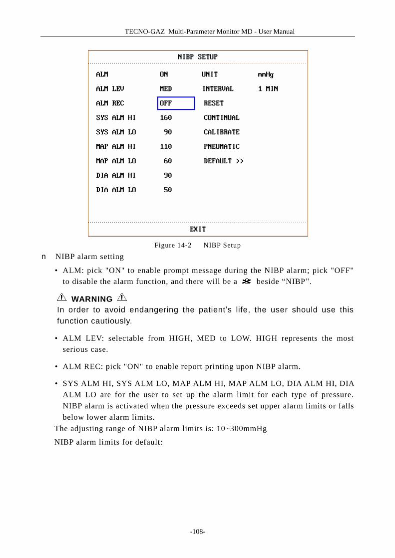
TECNO-GAZ Multi-Parameter Monitor MD - User Manual
-108-
Figure 14-2 NIBP Setup
n NIBP alarm setting
• ALM: pick "ON" to enable prompt message during the NIBP alarm; pick "OFF" to disable the alarm function, and there will be a beside “NIBP”.
WARNING In order to avoid endangering the patient’s life, the user should use this function cautiously.
• ALM LEV: selectable from HIGH, MED to LOW. HIGH represents the most serious case.
• ALM REC: pick "ON" to enable report printing upon NIBP alarm.
• SYS ALM HI, SYS ALM LO, MAP ALM HI, MAP ALM LO, DIA ALM HI, DIA ALM LO are for the user to set up the alarm limit for each type of pressure. NIBP alarm is activated when the pressure exceeds set upper alarm limits or falls below lower alarm limits.
The adjusting range of NIBP alarm limits is: 10~300mmHg
NIBP alarm limits for default:
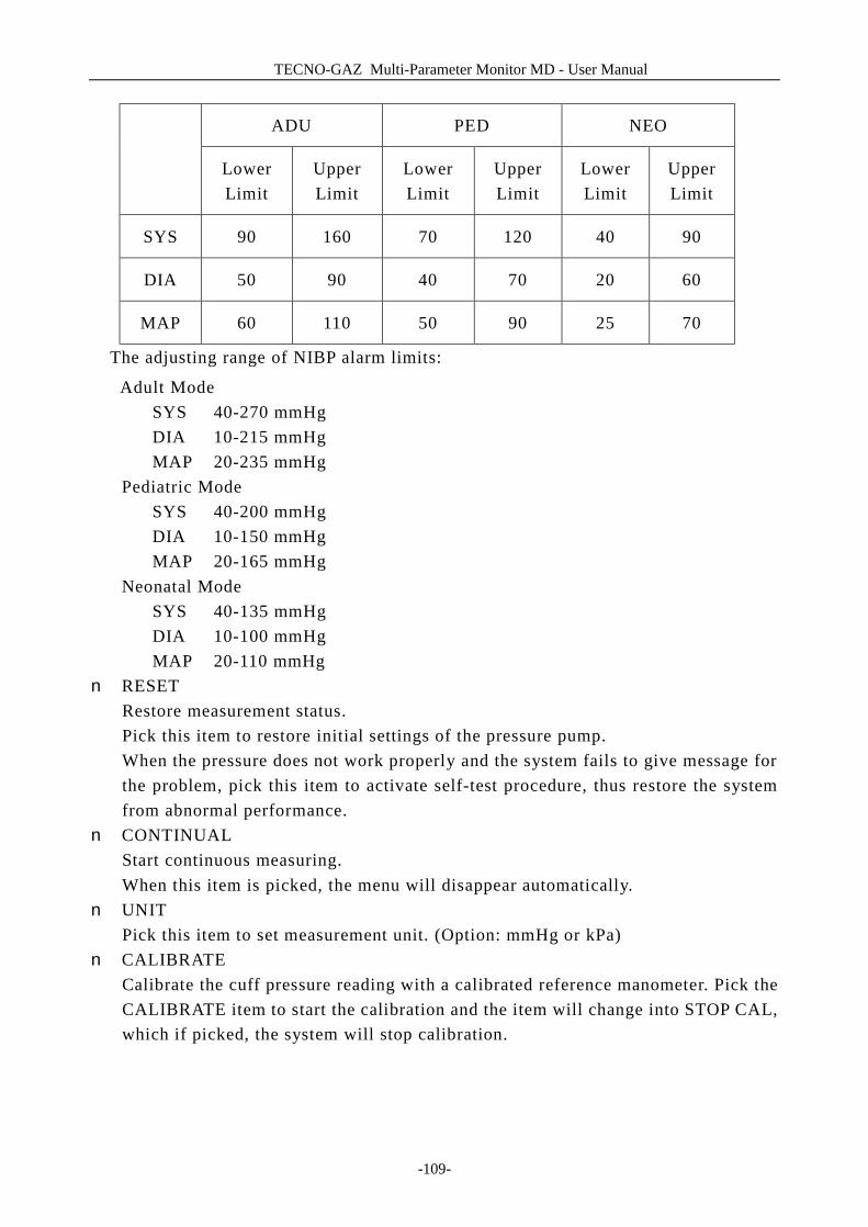
TECNO-GAZ Multi-Parameter Monitor MD - User Manual
-109-
ADU PED NEO
Lower Limit
Upper Limit
Lower Limit
Upper Limit
Lower Limit
Upper Limit
SYS 90 160 70 120 40 90
DIA 50 90 40 70 20 60
MAP 60 110 50 90 25 70
The adjusting range of NIBP alarm limits:
Adult Mode SYS 40-270 mmHg DIA 10-215 mmHg MAP 20-235 mmHg Pediatric Mode SYS 40-200 mmHg DIA 10-150 mmHg MAP 20-165 mmHg Neonatal Mode SYS 40-135 mmHg DIA 10-100 mmHg MAP 20-110 mmHg n RESET
Restore measurement status. Pick this item to restore initial settings of the pressure pump. When the pressure does not work properly and the system fails to give message for the problem, pick this item to activate self-test procedure, thus restore the system from abnormal performance.
n CONTINUAL Start continuous measuring. When this item is picked, the menu will disappear automatically.
n UNIT Pick this item to set measurement unit. (Option: mmHg or kPa)
n CALIBRATE Calibrate the cuff pressure reading with a calibrated reference manometer. Pick the CALIBRATE item to start the calibration and the item will change into STOP CAL, which if picked, the system will stop calibration.
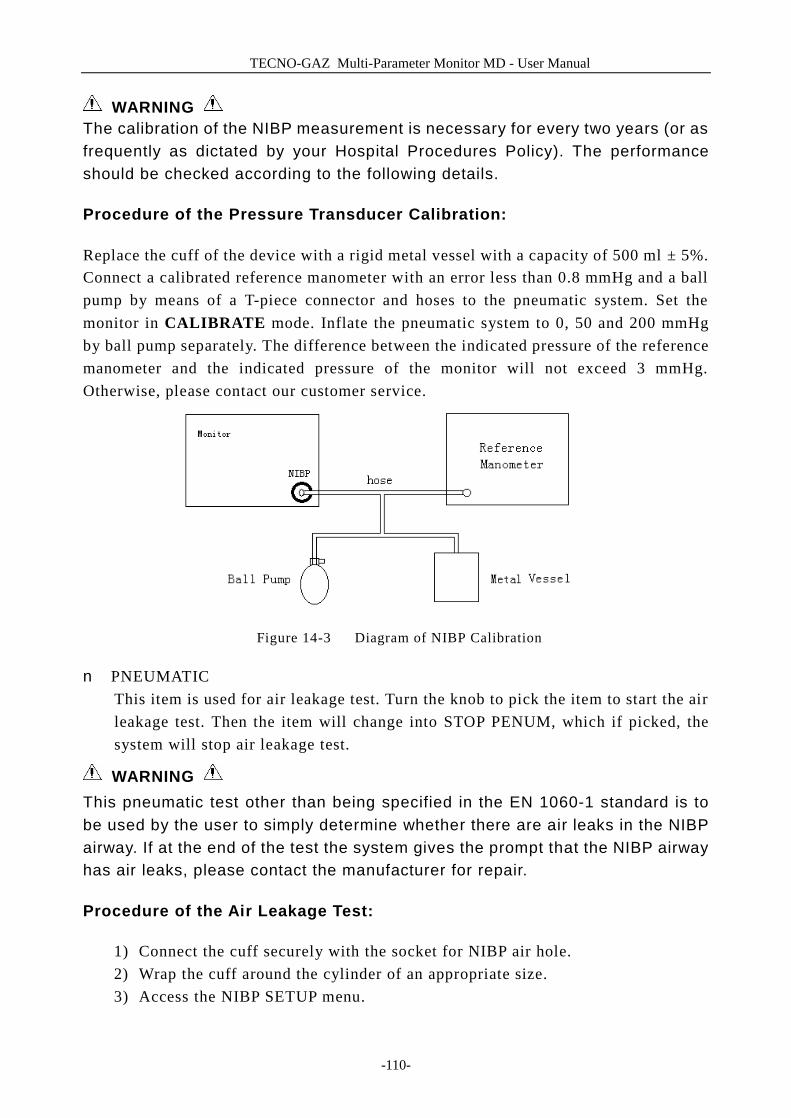
TECNO-GAZ Multi-Parameter Monitor MD - User Manual
-110-
WARNING The calibration of the NIBP measurement is necessary for every two years (or as frequently as dictated by your Hospital Procedures Policy). The performance should be checked according to the following details.
Procedure of the Pressure Transducer Calibration:
Replace the cuff of the device with a rigid metal vessel with a capacity of 500 ml ± 5%. Connect a calibrated reference manometer with an error less than 0.8 mmHg and a ball pump by means of a T-piece connector and hoses to the pneumatic system. Set the monitor in CALIBRATE mode. Inflate the pneumatic system to 0, 50 and 200 mmHg by ball pump separately. The difference between the indicated pressure of the reference manometer and the indicated pressure of the monitor will not exceed 3 mmHg. Otherwise, please contact our customer service.
Figure 14-3 Diagram of NIBP Calibration
n PNEUMATIC This item is used for air leakage test. Turn the knob to pick the item to start the air leakage test. Then the item will change into STOP PENUM, which if picked, the system will stop air leakage test.
WARNING This pneumatic test other than being specified in the EN 1060-1 standard is to be used by the user to simply determine whether there are air leaks in the NIBP airway. If at the end of the test the system gives the prompt that the NIBP airway has air leaks, please contact the manufacturer for repair.
Procedure of the Air Leakage Test:
1) Connect the cuff securely with the socket for NIBP air hole. 2) Wrap the cuff around the cylinder of an appropriate size. 3) Access the NIBP SETUP menu.
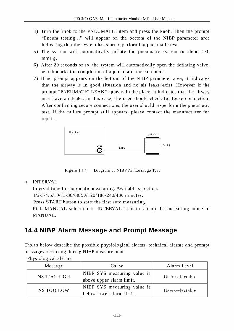
TECNO-GAZ Multi-Parameter Monitor MD - User Manual
-111-
4) Turn the knob to the PNEUMATIC item and press the knob. Then the prompt “Pneum testing…” will appear on the bottom of the NIBP parameter area indicating that the system has started performing pneumatic test.
5) The system will automatically inflate the pneumatic system to about 180 mmHg.
6) After 20 seconds or so, the system will automatically open the deflating valve, which marks the completion of a pneumatic measurement.
7) If no prompt appears on the bottom of the NIBP parameter area, it indicates that the airway is in good situation and no air leaks exist. However if the prompt “PNEUMATIC LEAK” appears in the place, it indicates that the airway may have air leaks. In this case, the user should check for loose connection. After confirming secure connections, the user should re-perform the pneumatic test. If the failure prompt still appears, please contact the manufacturer for repair.
Figure 14-4 Diagram of NIBP Air Leakage Test
n INTERVAL Interval time for automatic measuring. Available selection: 1/2/3/4/5/10/15/30/60/90/120/180/240/480 minutes. Press START button to start the first auto measuring. Pick MANUAL selection in INTERVAL item to set up the measuring mode to MANUAL.
14.4 NIBP Alarm Message and Prompt Message
Tables below describe the possible physiological alarms, technical alarms and prompt messages occurring during NIBP measurement.
Physiological alarms: Message Cause Alarm Level
NS TOO HIGH NIBP SYS measuring value is above upper alarm limit.
User-selectable
NS TOO LOW NIBP SYS measuring value is below lower alarm limit.
User-selectable
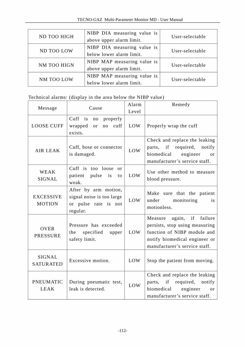
TECNO-GAZ Multi-Parameter Monitor MD - User Manual
-112-
ND TOO HIGH NIBP DIA measuring value is above upper alarm limit.
User-selectable
ND TOO LOW NIBP DIA measuring value is below lower alarm limit.
User-selectable
NM TOO HIGN NIBP MAP measuring value is above upper alarm limit.
User-selectable
NM TOO LOW NIBP MAP measuring value is below lower alarm limit.
User-selectable
Technical alarms: (display in the area below the NIBP value)
Message Cause Alarm Level
Remedy
LOOSE CUFF Cuff is no properly wrapped or no cuff exists.
LOW Properly wrap the cuff
AIR LEAK Cuff, hose or connector is damaged.
LOW
Check and replace the leaking parts, if required, notify biomedical engineer or manufacturer ’s service staff.
WEAK SIGNAL
Cuff is too loose or patient pulse is to weak.
LOW Use other method to measure blood pressure.
EXCESSIVE MOTION
After by arm motion, signal noise is too large or pulse rate is not regular.
LOW Make sure that the patient under monitoring is motionless.
OVER PRESSURE
Pressure has exceeded the specified upper safety limit.
LOW
Measure again, if failure persists, stop using measuring function of NIBP module and notify biomedical engineer or manufacturer ’s service staff.
SIGNAL SATURATED
Excessive motion. LOW Stop the patient from moving.
PNEUMATIC LEAK
During pneumatic test, leak is detected.
LOW
Check and replace the leaking parts, if required, notify biomedical engineer or manufacturer ’s service staff.
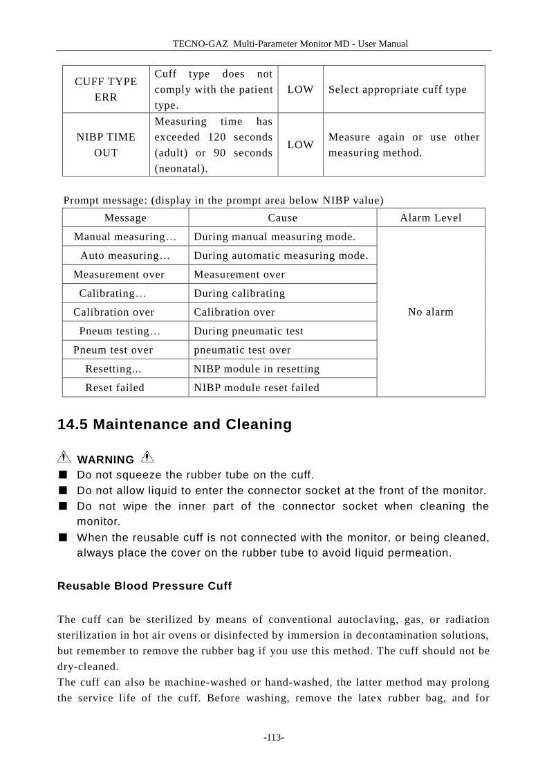
TECNO-GAZ Multi-Parameter Monitor MD - User Manual
-113-
CUFF TYPE ERR
Cuff type does not comply with the patient type.
LOW Select appropriate cuff type
NIBP TIME OUT
Measuring time has exceeded 120 seconds (adult) or 90 seconds (neonatal).
LOW Measure again or use other measuring method.
Prompt message: (display in the prompt area below NIBP value)
Message Cause Alarm Level
Manual measuring… During manual measuring mode.
Auto measuring… During automatic measuring mode.
Measurement over Measurement over
Calibrating… During calibrating
Calibration over Calibration over
Pneum testing… During pneumatic test
Pneum test over pneumatic test over
Resetting... NIBP module in resetting
Reset failed NIBP module reset failed
No alarm
14.5 Maintenance and Cleaning
WARNING ■ Do not squeeze the rubber tube on the cuff. ■ Do not allow liquid to enter the connector socket at the front of the monitor. ■ Do not wipe the inner part of the connector socket when cleaning the
monitor. ■ When the reusable cuff is not connected with the monitor, or being cleaned,
always place the cover on the rubber tube to avoid liquid permeation.
Reusable Blood Pressure Cuff
The cuff can be sterilized by means of conventional autoclaving, gas, or radiation sterilization in hot air ovens or disinfected by immersion in decontamination solutions, but remember to remove the rubber bag if you use this method. The cuff should not be dry-cleaned. The cuff can also be machine-washed or hand-washed, the latter method may prolong the service life of the cuff. Before washing, remove the latex rubber bag, and for
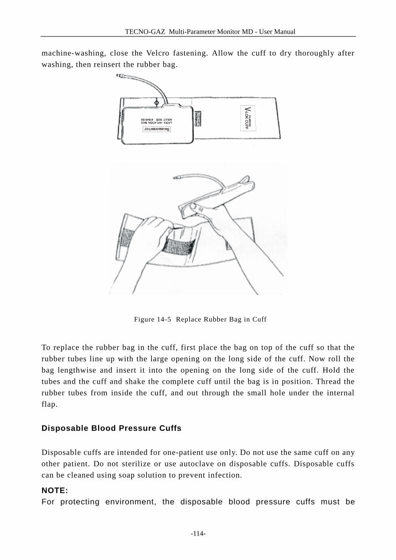
TECNO-GAZ Multi-Parameter Monitor MD - User Manual
-114-
machine-washing, close the Velcro fastening. Allow the cuff to dry thoroughly after washing, then reinsert the rubber bag.
Figure 14-5 Replace Rubber Bag in Cuff
To replace the rubber bag in the cuff, first place the bag on top of the cuff so that the rubber tubes line up with the large opening on the long side of the cuff. Now roll the bag lengthwise and insert it into the opening on the long side of the cuff. Hold the tubes and the cuff and shake the complete cuff until the bag is in position. Thread the rubber tubes from inside the cuff, and out through the small hole under the internal flap.
Disposable Blood Pressure Cuffs
Disposable cuffs are intended for one-patient use only. Do not use the same cuff on any other patient. Do not sterilize or use autoclave on disposable cuffs. Disposable cuffs can be cleaned using soap solution to prevent infection.
NOTE: For protecting environment, the disposable blood pressure cuffs must be

TECNO-GAZ Multi-Parameter Monitor MD - User Manual
-115-
recycled or disposed of properly.
TECNO-GAZ Multi-Parameter Monitor MD - User Manual
-116-
15 TEMP Monitoring
15.1 TEMP Monitoring
Two TEMP probes can be used simultaneously to measure two TEMP datas, and get the temperature difference.
TEMP Monitoring Setup
n If you are using disposable TEMP probes you need to plug the TEMP cable into the monitor and then connect the probe to the cable. With a reusable TEMP probe you can plug the probe directly into the monitor.
n Apply the TEMP probe(s) securely to the patient. n Switch on the system.
WARNING Verify probe cables fault detection before beginning of monitoring phase. Unplug the temperature probe cable of the channe1 from the socket, the screen will display the error message “TEMP1 SENSOR OFF” and the audible alarm is activated. The other channel is the same. NOTE: Disposable TEMP probe can only be used once for one patient.
WARNING The calibration of the temperature measurement is necessary for every two years (or as frequently as dictated by your Hospital Procedures Policy). When you need calibrate the temperature measurement, contact the manufacture please.
WARNING Take the TEMP probe and cable carefully. If not use, you should coil up the probe and cable into a loose circle. If the wire inside the cable is tensely pulled, it may cause mechanical damage to the probe and the cable.
WARNING The TEMP module shall be calibrated once every two years (or as required by your hospital’s regulation). When calibration is required, contact the manufacture please.
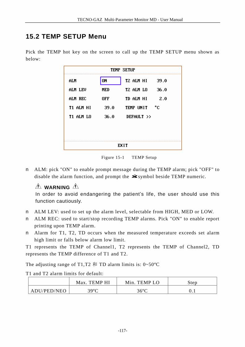
TECNO-GAZ Multi-Parameter Monitor MD - User Manual
-117-
15.2 TEMP SETUP Menu
Pick the TEMP hot key on the screen to call up the TEMP SETUP menu shown as below:
Figure 15-1 TEMP Setup
n ALM: pick "ON" to enable prompt message during the TEMP alarm; pick "OFF" to disable the alarm function, and prompt the symbol beside TEMP numeric.
WARNING In order to avoid endangering the patient’s life, the user should use this function cautiously.
n ALM LEV: used to set up the alarm level, selectable from HIGH, MED or LOW. n ALM REC: used to start/stop recording TEMP alarms. Pick "ON" to enable report
printing upon TEMP alarm. n Alarm for T1, T2, TD occurs when the measured temperature exceeds set alarm
high limit or falls below alarm low limit. T1 represents the TEMP of Channel1, T2 represents the TEMP of Channel2, TD represents the TEMP difference of T1 and T2.
The adjusting range of T1,T2 和 TD alarm limits is: 0~50ºC
T1 and T2 alarm limits for default:
Max. TEMP HI Min. TEMP LO Step
ADU/PED/NEO 39ºC 36ºC 0.1

TECNO-GAZ Multi-Parameter Monitor MD - User Manual
-118-
TD alarm limits for default:
TEMP HI Step
ADU/PED/NEO 2ºC 0.1 n UNIT: To set temperature unit (ºC or ºF). n DEFAULT: Pick this item to access the TEMP DEFAULT CONFIG dialog box,
in which the user may select whether the FACTORY DEFAULT CONFIG or the USER DEFAULT CONFIG is to be used. After selecting any of the items and exiting the dialog box, the system will pop up the dialog box asking for the user’s confirmation.
15.3 TEMP Alarm Message
Tables below describe the possible physiological alarms, technical alarms occurring during TEMP measurement. Physiological alarms:
Message Cause Alarm Level
T1 TOO HIGH Measuring value of T1 channel is above upper alarm limit.
User-selectable
T1 TOO LOW Measuring value of T1 channel is below lower alarm limit.
User-selectable
T2 TOO HIGH Measuring value of T2 channel is above upper alarm limit.
User-selectable
T2 TOO LOW Measuring value of T2 channel is below lower alarm limit.
User-selectable
TD TOO HIGH Temperature difference of T1 and T2 is above upper temperature difference limit.
User-selectable
Technical alarms:
Alarm Message Cause Alarm Level
Remedy
TEMP1 SENSOR OFF
Temperature cable of TEMP channe1 may be disconnected from the monitor.
LOW Make sure that
the cable is properly connected

TECNO-GAZ Multi-Parameter Monitor MD - User Manual
-119-
TEMP2 SENSOR OFF
Temperature cable of TEMP channe2 may be disconnected from the monitor.
LOW Make sure that
the cable is properly connected.
15.4 Care and Cleaning
WARNING Before cleaning the monitor or the probe, make sure that the equipment is switched off and disconnected from the power line.
Reusable TEMP Probes
1 The TEMP probe should not be heated above 100℃ (212℉). It should only be subjected briefly to temperatures between 80℃ (176℉) and 100℃ (212℉).
2 The probe must not be sterilized in steam. 3 Only detergents containing no alcohol can be used for disaffection. 4 The rectal probes should be used, if possible, in conjunction with a protective
rubber cover. 5 To clean the probe, hold the tip with one hand and with the other hand rubbing the
probe down in the direction of the connector using a moist lint-free cloth. NOTE: Wash the probe with clean water after disinfecting and sterilizing to remove any remaining solution. The probe can only be reused after being dried thoroughly. NOTE: Do not disinfect the probe with the means of water boiled.
NOTE: The product has not been disinfected at the factory.
NOTE: Any residue should be removed from the probe before being disinfected and sterilized, and avoid contacting corrosive solvent. Dip the cable into alcohol or alkalescent solvent for a long time, may reduce the flexibility of the scarfskin of the cable. Also, the connector should not be dipped.
TECNO-GAZ Multi-Parameter Monitor MD - User Manual
-120-
NOTE: After monitoring, disinfect the probe according to the instruction described in the user manual. NOTE: Disposable TEMP probe must not be re-sterilized or reused. NOTE: Cavity temperature probe only suggested to be used inside the recta. Recommend to use the disposable cannula to prevent cross infection. NOTE: For protecting environment, the disposable TEMP probe must be recycled or disposed of properly. NOTE: Do not force the cavity temperature probe against resistance when inserted into human body. Also it is not recommended to use it in bleeding part and cankerous part of human body.
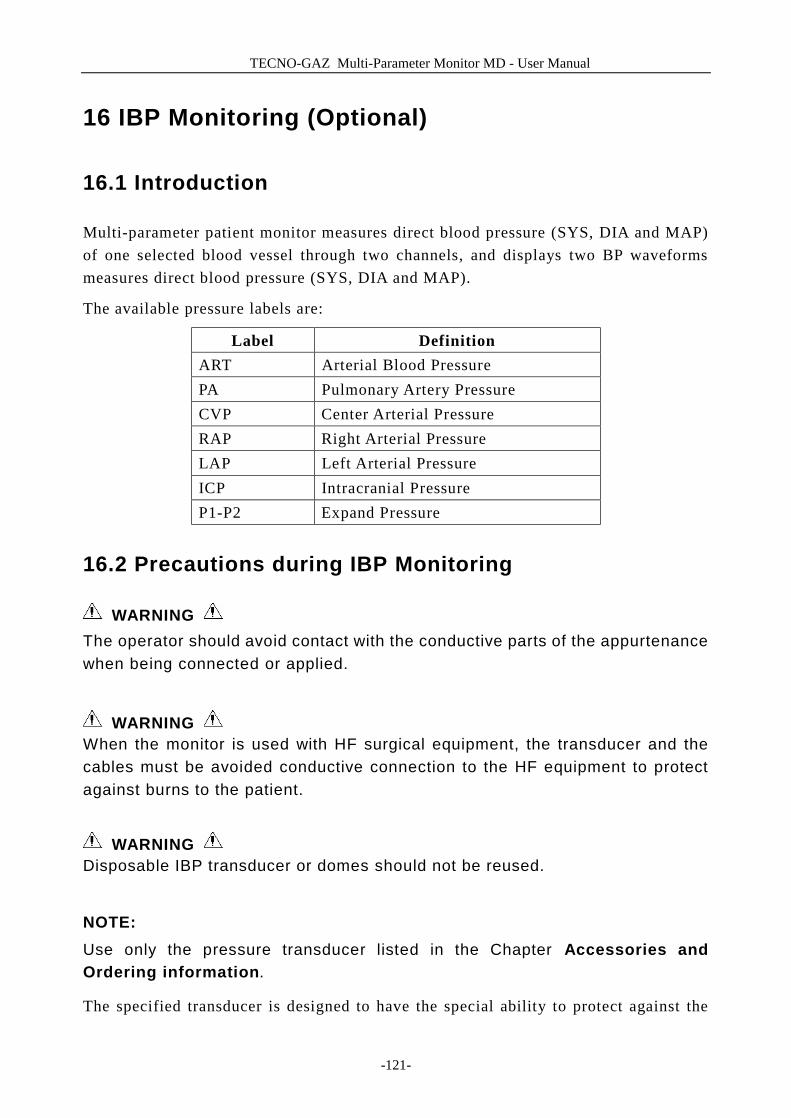
TECNO-GAZ Multi-Parameter Monitor MD - User Manual
-121-
16 IBP Monitoring (Optional)
16.1 Introduction
Multi-parameter patient monitor measures direct blood pressure (SYS, DIA and MAP) of one selected blood vessel through two channels, and displays two BP waveforms measures direct blood pressure (SYS, DIA and MAP).
The available pressure labels are:
Label Definition ART Arterial Blood Pressure PA Pulmonary Artery Pressure CVP Center Arterial Pressure RAP Right Arterial Pressure LAP Left Arterial Pressure ICP Intracranial Pressure P1-P2 Expand Pressure
16.2 Precautions during IBP Monitoring
WARNING The operator should avoid contact with the conductive parts of the appurtenance when being connected or applied.
WARNING When the monitor is used with HF surgical equipment, the transducer and the cables must be avoided conductive connection to the HF equipment to protect against burns to the patient.
WARNING Disposable IBP transducer or domes should not be reused.
NOTE: Use only the pressure transducer listed in the Chapter Accessories and Ordering information.
The specified transducer is designed to have the special ability to protect against the
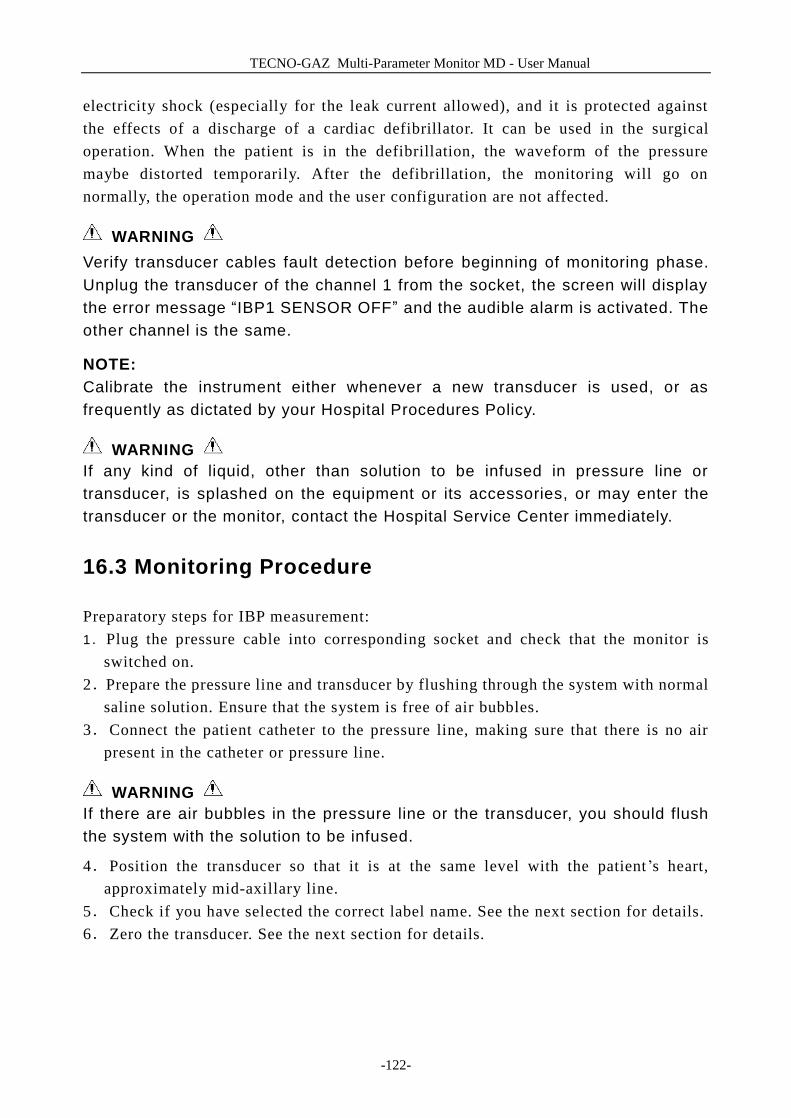
TECNO-GAZ Multi-Parameter Monitor MD - User Manual
-122-
electricity shock (especially for the leak current allowed), and it is protected against the effects of a discharge of a cardiac defibrillator. It can be used in the surgical operation. When the patient is in the defibrillation, the waveform of the pressure maybe distorted temporarily. After the defibrillation, the monitoring will go on normally, the operation mode and the user configuration are not affected.
WARNING Verify transducer cables fault detection before beginning of monitoring phase. Unplug the transducer of the channel 1 from the socket, the screen will display the error message “IBP1 SENSOR OFF” and the audible alarm is activated. The other channel is the same.
NOTE: Calibrate the instrument either whenever a new transducer is used, or as frequently as dictated by your Hospital Procedures Policy.
WARNING If any kind of liquid, other than solution to be infused in pressure line or transducer, is splashed on the equipment or its accessories, or may enter the transducer or the monitor, contact the Hospital Service Center immediately.
16.3 Monitoring Procedure
Preparatory steps for IBP measurement: 1.Plug the pressure cable into corresponding socket and check that the monitor is
switched on. 2.Prepare the pressure line and transducer by flushing through the system with normal
saline solution. Ensure that the system is free of air bubbles. 3.Connect the patient catheter to the pressure line, making sure that there is no air
present in the catheter or pressure line.
WARNING If there are air bubbles in the pressure line or the transducer, you should flush the system with the solution to be infused.
4.Position the transducer so that it is at the same level with the patient’s heart, approximately mid-axillary line.
5.Check if you have selected the correct label name. See the next section for details. 6.Zero the transducer. See the next section for details.
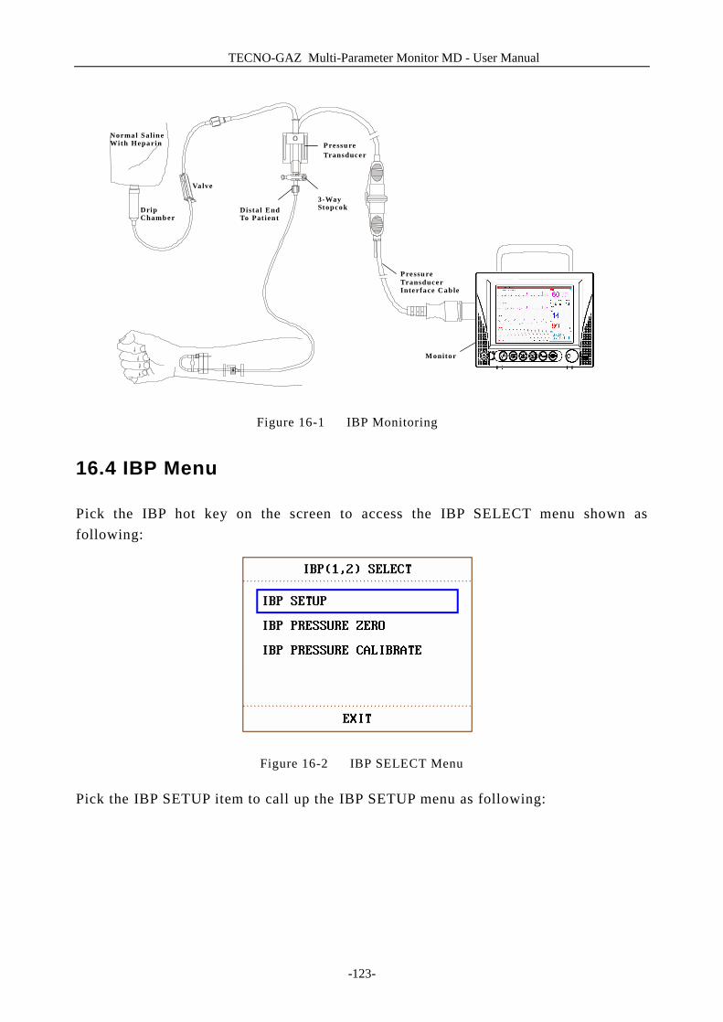
TECNO-GAZ Multi-Parameter Monitor MD - User Manual
-123-
Figure 16-1 IBP Monitoring
16.4 IBP Menu
Pick the IBP hot key on the screen to access the IBP SELECT menu shown as following:
Figure 16-2 IBP SELECT Menu
Pick the IBP SETUP item to call up the IBP SETUP menu as following:
Normal Saline With Heparin
Drip Chamber
Va lve
Transducer
3-Way Stopcok Dista l End
To Pat ient
Monitor
Pressure Transducer
Interface Cab le
Pressure
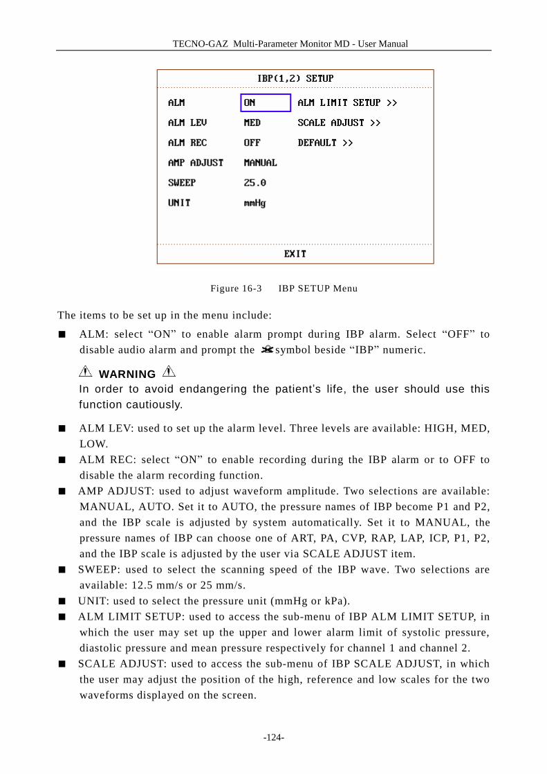
TECNO-GAZ Multi-Parameter Monitor MD - User Manual
-124-
Figure 16-3 IBP SETUP Menu
The items to be set up in the menu include:
■ ALM: select “ON” to enable alarm prompt during IBP alarm. Select “OFF” to disable audio alarm and prompt the symbol beside “IBP” numeric.
WARNING In order to avoid endangering the patient’s life, the user should use this function cautiously.
■ ALM LEV: used to set up the alarm level. Three levels are available: HIGH, MED, LOW.
■ ALM REC: select “ON” to enable recording during the IBP alarm or to OFF to disable the alarm recording function.
■ AMP ADJUST: used to adjust waveform amplitude. Two selections are available: MANUAL, AUTO. Set it to AUTO, the pressure names of IBP become P1 and P2, and the IBP scale is adjusted by system automatically. Set it to MANUAL, the pressure names of IBP can choose one of ART, PA, CVP, RAP, LAP, ICP, P1, P2, and the IBP scale is adjusted by the user via SCALE ADJUST item.
■ SWEEP: used to select the scanning speed of the IBP wave. Two selections are available: 12.5 mm/s or 25 mm/s.
■ UNIT: used to select the pressure unit (mmHg or kPa). ■ ALM LIMIT SETUP: used to access the sub-menu of IBP ALM LIMIT SETUP, in
which the user may set up the upper and lower alarm limit of systolic pressure, diastolic pressure and mean pressure respectively for channel 1 and channel 2.
■ SCALE ADJUST: used to access the sub-menu of IBP SCALE ADJUST, in which the user may adjust the position of the high, reference and low scales for the two waveforms displayed on the screen.
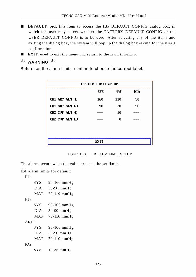
TECNO-GAZ Multi-Parameter Monitor MD - User Manual
-125-
■ DEFAULT: pick this item to access the IBP DEFAULT CONFIG dialog box, in which the user may select whether the FACTORY DEFAULT CONFIG or the USER DEFAULT CONFIG is to be used. After selecting any of the items and exiting the dialog box, the system will pop up the dialog box asking for the user’s confirmation.
■ EXIT: used to exit the menu and return to the main interface.
WARNING Before set the alarm limits, confirm to choose the correct label.
Figure 16-4 IBP ALM LIMIT SETUP
The alarm occurs when the value exceeds the set limits.
IBP alarm limits for default: P1:
SYS 90-160 mmHg DIA 50-90 mmHg MAP 70-110 mmHg
P2: SYS 90-160 mmHg
DIA 50-90 mmHg MAP 70-110 mmHg
ART: SYS 90-160 mmHg
DIA 50-90 mmHg MAP 70-110 mmHg
PA: SYS 10-35 mmHg
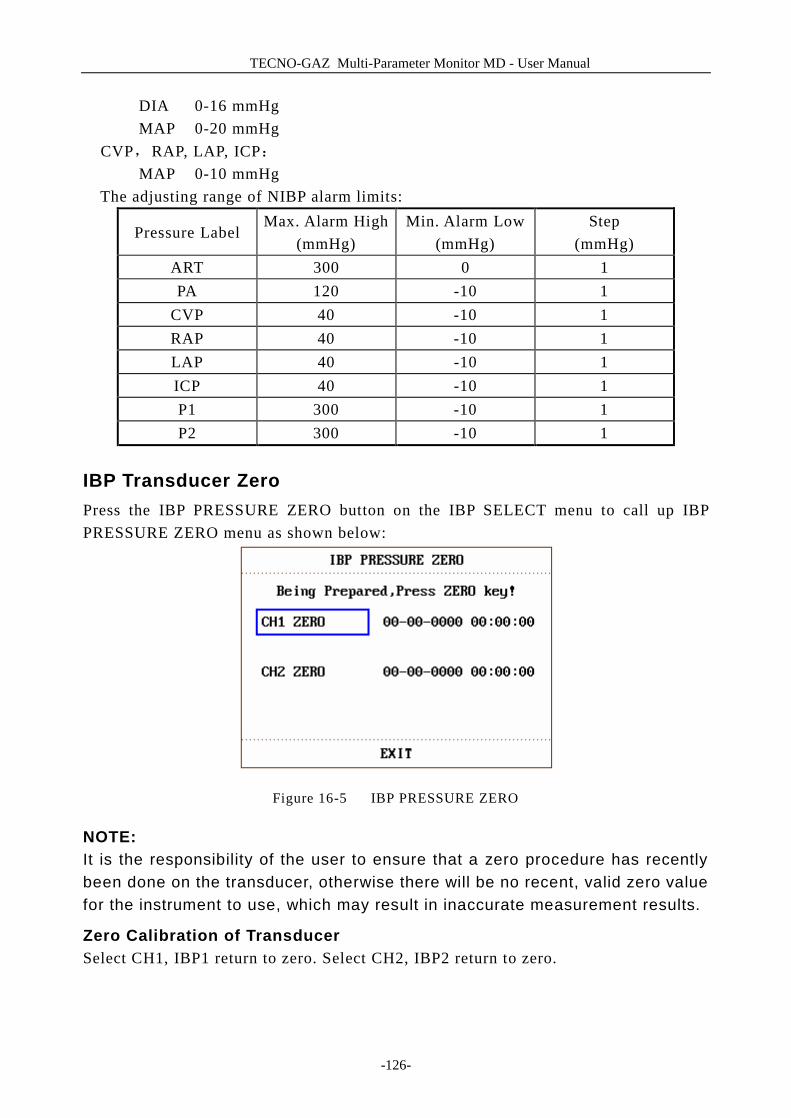
TECNO-GAZ Multi-Parameter Monitor MD - User Manual
-126-
DIA 0-16 mmHg MAP 0-20 mmHg
CVP,RAP, LAP, ICP: MAP 0-10 mmHg
The adjusting range of NIBP alarm limits:
Pressure Label Max. Alarm High
(mmHg) Min. Alarm Low
(mmHg) Step
(mmHg) ART 300 0 1 PA 120 -10 1
CVP 40 -10 1 RAP 40 -10 1 LAP 40 -10 1 ICP 40 -10 1 P1 300 -10 1 P2 300 -10 1
IBP Transducer Zero Press the IBP PRESSURE ZERO button on the IBP SELECT menu to call up IBP PRESSURE ZERO menu as shown below:
Figure 16-5 IBP PRESSURE ZERO
NOTE: It is the responsibility of the user to ensure that a zero procedure has recently been done on the transducer, otherwise there will be no recent, valid zero value for the instrument to use, which may result in inaccurate measurement results.
Zero Calibration of Transducer Select CH1, IBP1 return to zero. Select CH2, IBP2 return to zero.
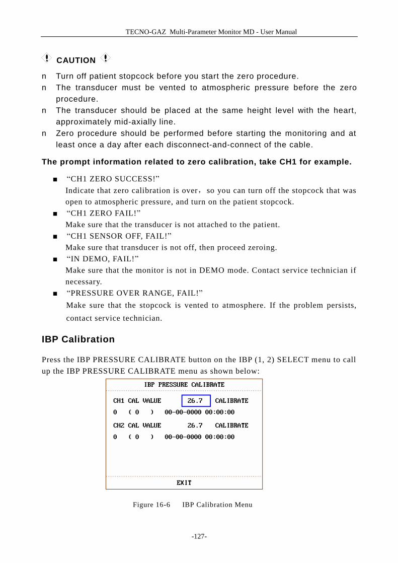
TECNO-GAZ Multi-Parameter Monitor MD - User Manual
-127-
CAUTION
n Turn off patient stopcock before you start the zero procedure. n The transducer must be vented to atmospheric pressure before the zero
procedure. n The transducer should be placed at the same height level with the heart,
approximately mid-axially line. n Zero procedure should be performed before starting the monitoring and at
least once a day after each disconnect-and-connect of the cable.
The prompt information related to zero calibration, take CH1 for example.
■ “CH1 ZERO SUCCESS!” Indicate that zero calibration is over,so you can turn off the stopcock that was open to atmospheric pressure, and turn on the patient stopcock.
■ “CH1 ZERO FAIL!” Make sure that the transducer is not attached to the patient.
■ “CH1 SENSOR OFF, FAIL!” Make sure that transducer is not off, then proceed zeroing.
■ “IN DEMO, FAIL!” Make sure that the monitor is not in DEMO mode. Contact service technician if necessary.
■ “PRESSURE OVER RANGE, FAIL!” Make sure that the stopcock is vented to atmosphere. If the problem persists, contact service technician.
IBP Calibration
Press the IBP PRESSURE CALIBRATE button on the IBP (1, 2) SELECT menu to call up the IBP PRESSURE CALIBRATE menu as shown below:
Figure 16-6 IBP Calibration Menu
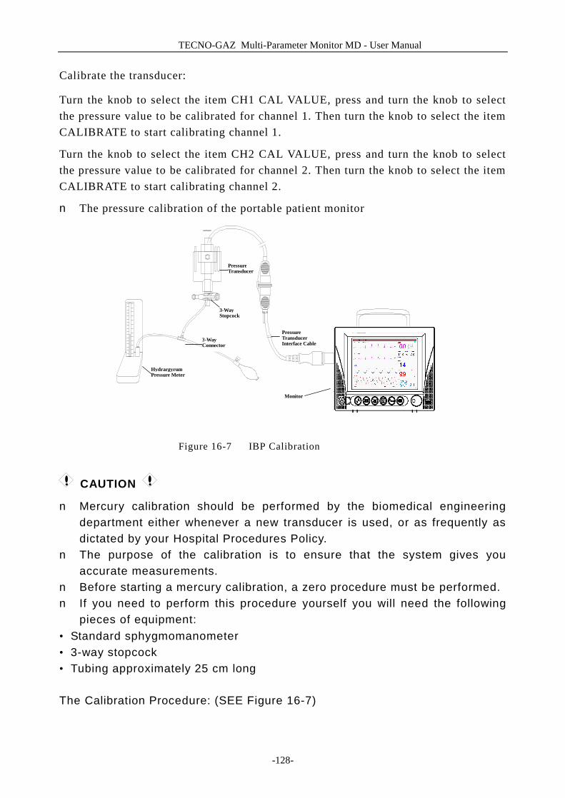
TECNO-GAZ Multi-Parameter Monitor MD - User Manual
-128-
Calibrate the transducer:
Turn the knob to select the item CH1 CAL VALUE, press and turn the knob to select the pressure value to be calibrated for channel 1. Then turn the knob to select the item CALIBRATE to start calibrating channel 1.
Turn the knob to select the item CH2 CAL VALUE, press and turn the knob to select the pressure value to be calibrated for channel 2. Then turn the knob to select the item CALIBRATE to start calibrating channel 2.
n The pressure calibration of the portable patient monitor
Figure 16-7 IBP Calibration
CAUTION
n Mercury calibration should be performed by the biomedical engineering department either whenever a new transducer is used, or as frequently as dictated by your Hospital Procedures Policy.
n The purpose of the calibration is to ensure that the system gives you accurate measurements.
n Before starting a mercury calibration, a zero procedure must be performed. n If you need to perform this procedure yourself you will need the following
pieces of equipment: • Standard sphygmomanometer • 3-way stopcock • Tubing approximately 25 cm long The Calibration Procedure: (SEE Figure 16-7)
Monitor
Pressure Transducer Interface Cable
Pressure Transducer
3-Way Stopcock
3-Way Connector
Hydrargyrum Pressure Meter
TECNO-GAZ Multi-Parameter Monitor MD - User Manual
-129-
WARNING You must never perform this procedure while patient is being monitored.
1. Close the stopcock that was open to atmospheric pressure for the zero calibration. 2. Attach the tubing to the sphygmomanometer. 3. Ensure that connection that would lead to patient is off. 4. Connect the 3-way connector to the 3-way stopcock that is not connected to the
patient catheter. 5. Open the port of the 3-way stopcock to the sphygmomanometer. 6. Select the channel to be calibrated in the menu and select the pressure value to
which the IBP is to be adjusted. 7. Inflate to make the mercury bar rise to the setup pressure value. 8. Adjust repeatedly until the value in the menu is equal to the pressure value shown
by the mercury calibration. 9. Press the Start button, the device will begin calibrating. 10. Wait for the calibrated result. You should take corresponding measures based on
the prompt information. 11. After calibration, disassemble the blood pressure tubing and the attached 3-way
valve.
The prompt information related to calibration, take CH1 for example.
■ “CH1 CAL SUCCESS!” Indicate that CH1 works normally, you can use CH1 to monitor the patient.
■ “CH1 CAL FAIL!” Make sure that pressure value shown by hydrargyrum pressure meter is change- less.
■ “CH1 SENSOR OFF, FAIL!” Make sure that sensor is not off, then proceed calibration.
■ “IN DEMO, FAIL!” Make sure that the monitor is not in DEMO mode. Contact service technician if necessary.
■ “PRESSURE OVER RANGE, FAIL!” Make sure that you have selected transducer value in IBP CAL, then proceed calibration.
IBP SCALE ADJUST Submenu
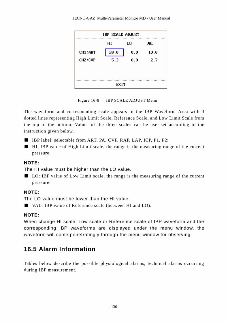
TECNO-GAZ Multi-Parameter Monitor MD - User Manual
-130-
Figure 16-8 IBP SCALE ADJUST Menu
The waveform and corresponding scale appears in the IBP Waveform Area with 3 dotted lines representing High Limit Scale, Reference Scale, and Low Limit Scale from the top to the bottom. Values of the three scales can be user-set according to the instruction given below.
■ IBP label: selectable from ART, PA, CVP, RAP, LAP, ICP, P1, P2; ■ HI: IBP value of High Limit scale, the range is the measuring range of the current
pressure.
NOTE: The HI value must be higher than the LO value. ■ LO: IBP value of Low Limit scale, the range is the measuring range of the current
pressure.
NOTE: The LO value must be lower than the HI value. ■ VAL: IBP value of Reference scale (between HI and LO).
NOTE: When change HI scale, Low scale or Reference scale of IBP waveform and the corresponding IBP waveforms are displayed under the menu window, the waveform will come penetratingly through the menu window for observing.
16.5 Alarm Information
Tables below describe the possible physiological alarms, technical alarms occurring during IBP measurement.
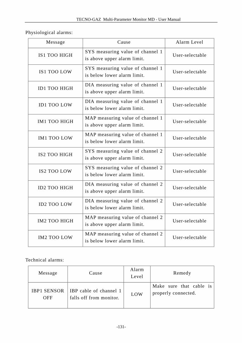
TECNO-GAZ Multi-Parameter Monitor MD - User Manual
-131-
Physiological alarms:
Message Cause Alarm Level
IS1 TOO HIGH SYS measuring value of channel 1 is above upper alarm limit.
User-selectable
IS1 TOO LOW SYS measuring value of channel 1 is below lower alarm limit.
User-selectable
ID1 TOO HIGH DIA measuring value of channel 1 is above upper alarm limit.
User-selectable
ID1 TOO LOW DIA measuring value of channel 1 is below lower alarm limit.
User-selectable
IM1 TOO HIGH MAP measuring value of channel 1 is above upper alarm limit.
User-selectable
IM1 TOO LOW MAP measuring value of channel 1 is below lower alarm limit.
User-selectable
IS2 TOO HIGH SYS measuring value of channel 2 is above upper alarm limit.
User-selectable
IS2 TOO LOW SYS measuring value of channel 2 is below lower alarm limit.
User-selectable
ID2 TOO HIGH DIA measuring value of channel 2 is above upper alarm limit.
User-selectable
ID2 TOO LOW DIA measuring value of channel 2 is below lower alarm limit.
User-selectable
IM2 TOO HIGH MAP measuring value of channel 2 is above upper alarm limit.
User-selectable
IM2 TOO LOW MAP measuring value of channel 2 is below lower alarm limit.
User-selectable
Technical alarms:
Message Cause Alarm Level
Remedy
IBP1 SENSOR OFF
IBP cable of channel 1 falls off from monitor.
LOW
Make sure that cable is properly connected.
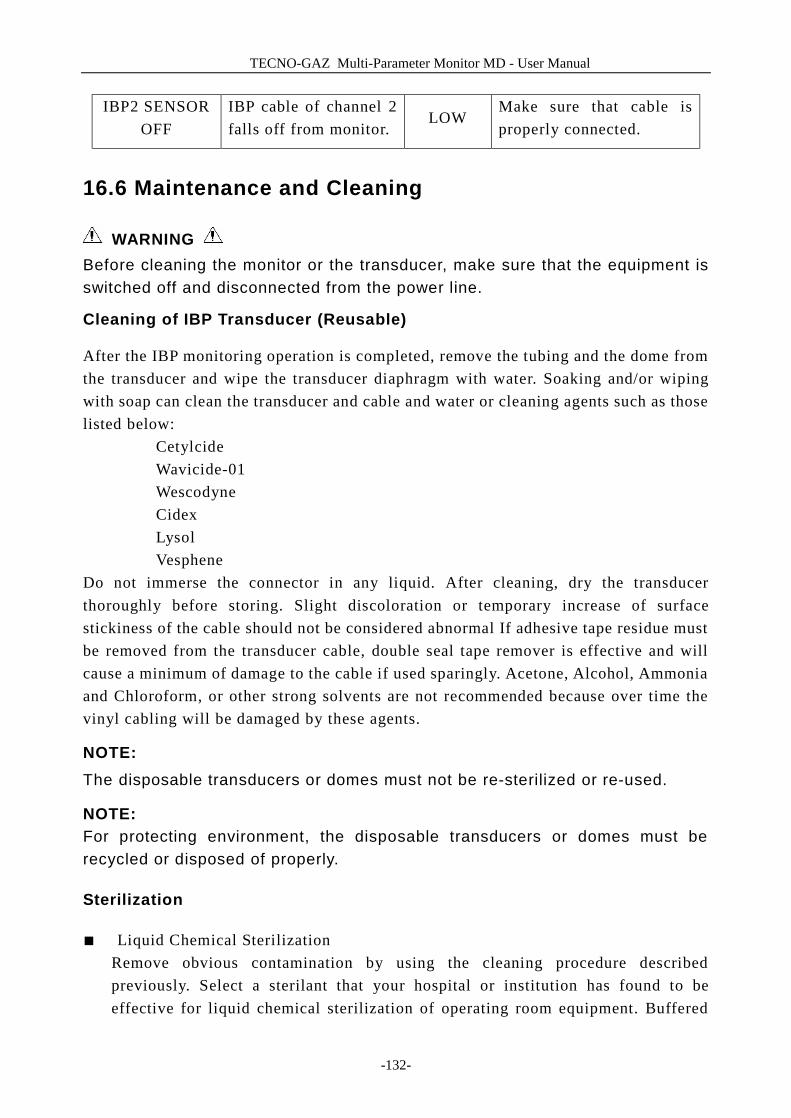
TECNO-GAZ Multi-Parameter Monitor MD - User Manual
-132-
IBP2 SENSOR OFF
IBP cable of channel 2 falls off from monitor.
LOW Make sure that cable is properly connected.
16.6 Maintenance and Cleaning
WARNING Before cleaning the monitor or the transducer, make sure that the equipment is switched off and disconnected from the power line.
Cleaning of IBP Transducer (Reusable)
After the IBP monitoring operation is completed, remove the tubing and the dome from the transducer and wipe the transducer diaphragm with water. Soaking and/or wiping with soap can clean the transducer and cable and water or cleaning agents such as those listed below:
Cetylcide Wavicide-01 Wescodyne Cidex Lysol Vesphene
Do not immerse the connector in any liquid. After cleaning, dry the transducer thoroughly before storing. Slight discoloration or temporary increase of surface stickiness of the cable should not be considered abnormal If adhesive tape residue must be removed from the transducer cable, double seal tape remover is effective and will cause a minimum of damage to the cable if used sparingly. Acetone, Alcohol, Ammonia and Chloroform, or other strong solvents are not recommended because over time the vinyl cabling will be damaged by these agents.
NOTE: The disposable transducers or domes must not be re-sterilized or re-used.
NOTE: For protecting environment, the disposable transducers or domes must be recycled or disposed of properly.
Sterilization
■ Liquid Chemical Sterilization Remove obvious contamination by using the cleaning procedure described previously. Select a sterilant that your hospital or institution has found to be effective for liquid chemical sterilization of operating room equipment. Buffered
TECNO-GAZ Multi-Parameter Monitor MD - User Manual
-133-
gluteraldehyed (e.g. Cidex or Hospisept) has been found to be effective. Do not use quaternary cationic detergents such as zephiran chloride. If the whole unit is to be sterilized, immerse the transducer but not the electrical connector into the sterilant for the recommended sterilizing period. Be sure that the dome is removed. Then rinse all transducer parts except the electrical connector with sterilized water or saline. The transducer must be thoroughly dried before storing.
■ Gas Sterilization For more complete asepsis, use gas sterilization. Remove obvious contamination by using the cleaning procedure described previously. To inhibit the formation of ethylene glycol when ethylene oxide gas is used as the disinfectant, the transducer should be completely dry. Follow the operating instructions provided by the manufacturer of the gas disinfectant.
WARNING The sterilize temperature must not exceed 70°C (158°F). Plastics in the pressure transducer may deform or melt above this temperature.

TECNO-GAZ Multi-Parameter Monitor MD - User Manual
-134-

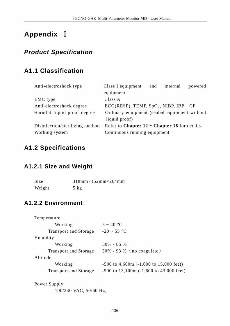
TECNO-GAZ Multi-Parameter Monitor MD - User Manual
-136-
Appendix Ⅰ
Product Specification
A1.1 Classification
Anti-electroshock type Class equipment Ⅰ and internal powered equipment
EMC type Class A Anti-electroshock degree ECG(RESP), TEMP, SpO2, NIBP, IBP CF Harmful liquid proof degree Ordinary equipment (sealed equipment without
liquid proof) Disinfection/sterilizing method Refer to Chapter 12 ~ Chapter 16 for details. Working system Continuous running equipment
A1.2 Specifications
A1.2.1 Size and Weight
Size 318mm×152mm×264mm Weight 5 kg
A1.2.2 Environment
Temperature Working 5 ~ 40 °C
Transport and Storage -20 ~ 55 °C Humidity
Working 30% - 85 % Transport and Storage 30% - 93 %(no coagulate)
Altitude Working -500 to 4,600m (-1,600 to 15,000 feet)
Transport and Storage -500 to 13,100m (-1,600 to 43,000 feet)
Power Supply 100/240 VAC, 50/60 Hz,
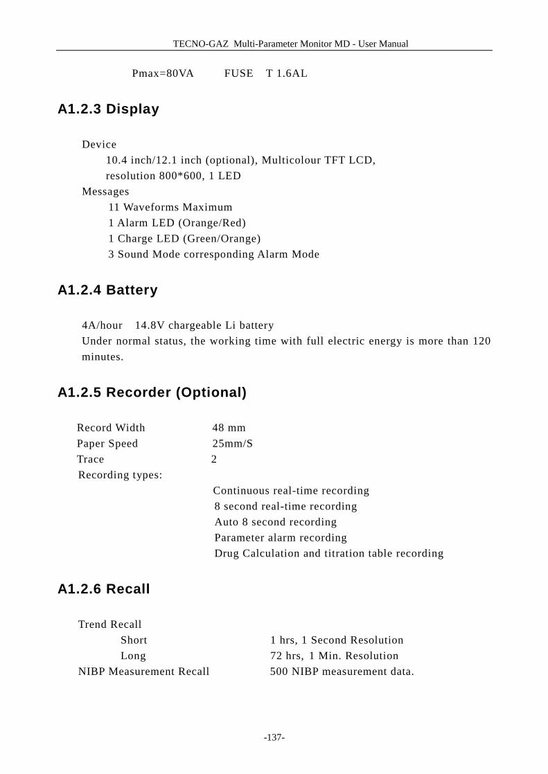
TECNO-GAZ Multi-Parameter Monitor MD - User Manual
-137-
Pmax=80VA FUSE T 1.6AL
A1.2.3 Display
Device 10.4 inch/12.1 inch (optional), Multicolour TFT LCD, resolution 800*600, 1 LED
Messages 11 Waveforms Maximum 1 Alarm LED (Orange/Red) 1 Charge LED (Green/Orange) 3 Sound Mode corresponding Alarm Mode
A1.2.4 Battery
4A/hour 14.8V chargeable Li battery Under normal status, the working time with full electric energy is more than 120 minutes.
A1.2.5 Recorder (Optional)
Record Width 48 mm Paper Speed 25mm/S Trace 2
Recording types: Continuous real-time recording 8 second real-time recording Auto 8 second recording Parameter alarm recording Drug Calculation and titration table recording
A1.2.6 Recall
Trend Recall Short 1 hrs, 1 Second Resolution Long 72 hrs, 1 Min. Resolution
NIBP Measurement Recall 500 NIBP measurement data.
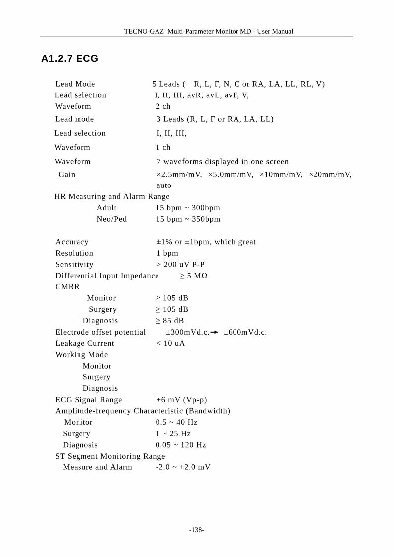
TECNO-GAZ Multi-Parameter Monitor MD - User Manual
-138-
A1.2.7 ECG
Lead Mode 5 Leads ( R, L, F, N, C or RA, LA, LL, RL, V) Lead selection I, II, III, avR, avL, avF, V, Waveform 2 ch Lead mode 3 Leads (R, L, F or RA, LA, LL)
Lead selection I, II, III,
Waveform 1 ch
Waveform 7 waveforms displayed in one screen Gain ×2.5mm/mV, ×5.0mm/mV, ×10mm/mV, ×20mm/mV,
auto HR Measuring and Alarm Range Adult 15 bpm ~ 300bpm Neo/Ped 15 bpm ~ 350bpm Accuracy ±1% or ±1bpm, which great Resolution 1 bpm Sensitivity > 200 uV P-P Differential Input Impedance ≥ 5 MΩ CMRR Monitor ≥ 105 dB
Surgery ≥ 105 dB Diagnosis ≥ 85 dB Electrode offset potential ±300mVd.c. ±600mVd.c. Leakage Current < 10 uA Working Mode Monitor Surgery Diagnosis ECG Signal Range ±6 mV (Vp-p) Amplitude-frequency Characteristic (Bandwidth)
Monitor 0.5 ~ 40 Hz Surgery 1 ~ 25 Hz Diagnosis 0.05 ~ 120 Hz
ST Segment Monitoring Range Measure and Alarm -2.0 ~ +2.0 mV
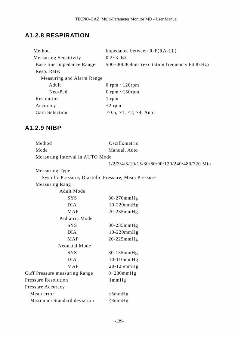
TECNO-GAZ Multi-Parameter Monitor MD - User Manual
-139-
A1.2.8 RESPIRATION
Method Impedance between R-F(RA-LL) Measuring Sensitivity 0.2~3.0Ω Base line Impedance Range 500~4000Ohms (excitation frequency 64.8kHz) Resp. Rate:
Measuring and Alarm Range Adult 0 rpm ~120rpm Neo/Ped 0 rpm ~150rpm
Resolution 1 rpm Accuracy ±2 rpm Gain Selection ×0.5, ×1, ×2, ×4, Auto
A1.2.9 NIBP
Method Oscillometric Mode Manual, Auto Measuring Interval in AUTO Mode
1/2/3/4/5/10/15/30/60/90/120/240/480/720 Min Measuring Type Systolic Pressure, Diastolic Pressure, Mean Pressure Measuring Rang
Adult Mode SYS 30-270mmHg DIA 10-220mmHg MAP 20-235mmHg
Pediatric Mode SYS 30-235mmHg DIA 10-220mmHg
MAP 20-225mmHg Neonatal Mode
SYS 30-135mmHg DIA 10-110mmHg MAP 20-125mmHg
Cuff Pressure measuring Range 0~280mmHg Pressure Resolution 1mmHg Pressure Accuracy
Mean error ±5mmHg Maximum Standard deviation ≤8mmHg
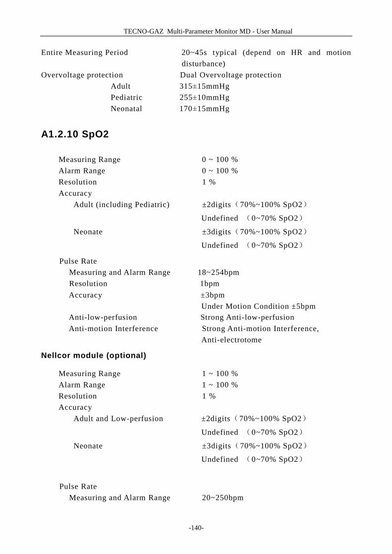
TECNO-GAZ Multi-Parameter Monitor MD - User Manual
-140-
Entire Measuring Period 20~45s typical (depend on HR and motion disturbance)
Overvoltage protection Dual Overvoltage protection Adult 315±15mmHg Pediatric 255±10mmHg Neonatal 170±15mmHg
A1.2.10 SpO2
Measuring Range 0 ~ 100 % Alarm Range 0 ~ 100 % Resolution 1 % Accuracy
Adult (including Pediatric) ±2digits(70%~100% SpO2)
Undefined (0~70% SpO2)
Neonate ±3digits(70%~100% SpO2)
Undefined (0~70% SpO2)
Pulse Rate Measuring and Alarm Range 18~254bpm Resolution 1bpm
Accuracy ±3bpm Under Motion Condition ±5bpm Anti-low-perfusion Strong Anti-low-perfusion Anti-motion Interference Strong Anti-motion Interference, Anti-electrotome
Nellcor module (optional)
Measuring Range 1 ~ 100 % Alarm Range 1 ~ 100 % Resolution 1 % Accuracy
Adult and Low-perfusion ±2digits(70%~100% SpO2)
Undefined (0~70% SpO2)
Neonate ±3digits(70%~100% SpO2)
Undefined (0~70% SpO2)
Pulse Rate
Measuring and Alarm Range 20~250bpm
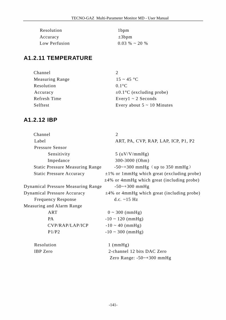
TECNO-GAZ Multi-Parameter Monitor MD - User Manual
-141-
Resolution 1bpm Accuracy ±3bpm Low Perfusion 0.03 % ~ 20 %
A1.2.11 TEMPERATURE
Channel 2 Measuring Range 15 ~ 45 °C Resolution 0.1°C Accuracy ±0.1°C (excluding probe) Refresh Time Every1 ~ 2 Seconds Selftest Every about 5 ~ 10 Minutes
A1.2.12 IBP
Channel 2 Label ART, PA, CVP, RAP, LAP, ICP, P1, P2
Pressure Sensor Sensitivity 5 (uV/V/mmHg)
Impedance 300-3000 (Ohm) Static Pressure Measuring Range -50~+300 mmHg(up to 350 mmHg)
Static Pressure Accuracy ±1% or 1mmHg which great (excluding probe) ±4% or 4mmHg which great (including probe) Dynamical Pressure Measuring Range -50~+300 mmHg Dynamical Pressure Accuracy ±4% or 4mmHg which great (including probe)
Frequency Response d.c. ~15 Hz Measuring and Alarm Range
ART 0 ~ 300 (mmHg) PA -10 ~ 120 (mmHg)
CVP/RAP/LAP/ICP -10 ~ 40 (mmHg) P1/P2 -10 ~ 300 (mmHg)
Resolution 1 (mmHg)
IBP Zero 2-channel 12 bits DAC Zero Zero Range: -50~+300 mmHg
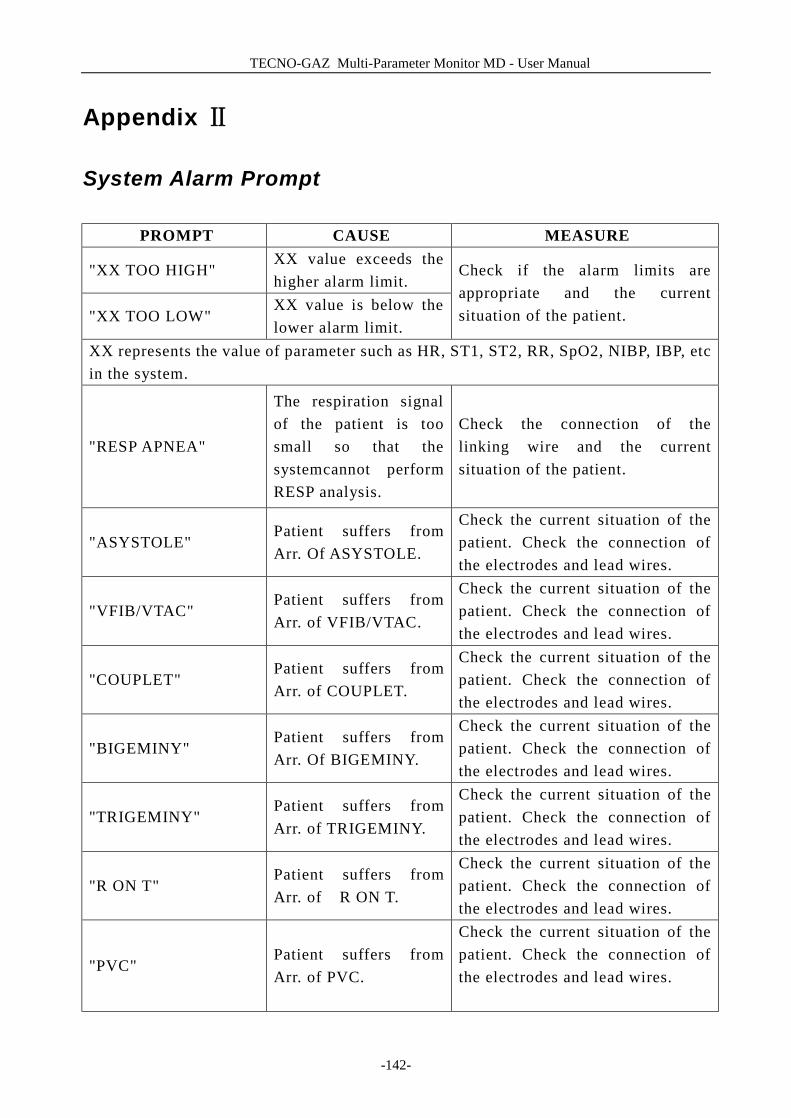
TECNO-GAZ Multi-Parameter Monitor MD - User Manual
-142-
Appendix Ⅱ
System Alarm Prompt
PROMPT CAUSE MEASURE
"XX TOO HIGH" XX value exceeds the higher alarm limit.
"XX TOO LOW" XX value is below the lower alarm limit.
Check if the alarm limits are appropriate and the current situation of the patient.
XX represents the value of parameter such as HR, ST1, ST2, RR, SpO2, NIBP, IBP, etc in the system.
"RESP APNEA"
The respiration signal of the patient is too small so that the systemcannot perform RESP analysis.
Check the connection of the linking wire and the current situation of the patient.
"ASYSTOLE" Patient suffers from Arr. Of ASYSTOLE.
Check the current situation of the patient. Check the connection of the electrodes and lead wires.
"VFIB/VTAC" Patient suffers from Arr. of VFIB/VTAC.
Check the current situation of the patient. Check the connection of the electrodes and lead wires.
"COUPLET" Patient suffers from Arr. of COUPLET.
Check the current situation of the patient. Check the connection of the electrodes and lead wires.
"BIGEMINY" Patient suffers from Arr. Of BIGEMINY.
Check the current situation of the patient. Check the connection of the electrodes and lead wires.
"TRIGEMINY" Patient suffers from Arr. of TRIGEMINY.
Check the current situation of the patient. Check the connection of the electrodes and lead wires.
"R ON T" Patient suffers from Arr. of R ON T.
Check the current situation of the patient. Check the connection of the electrodes and lead wires.
"PVC" Patient suffers from Arr. of PVC.
Check the current situation of the patient. Check the connection of the electrodes and lead wires.
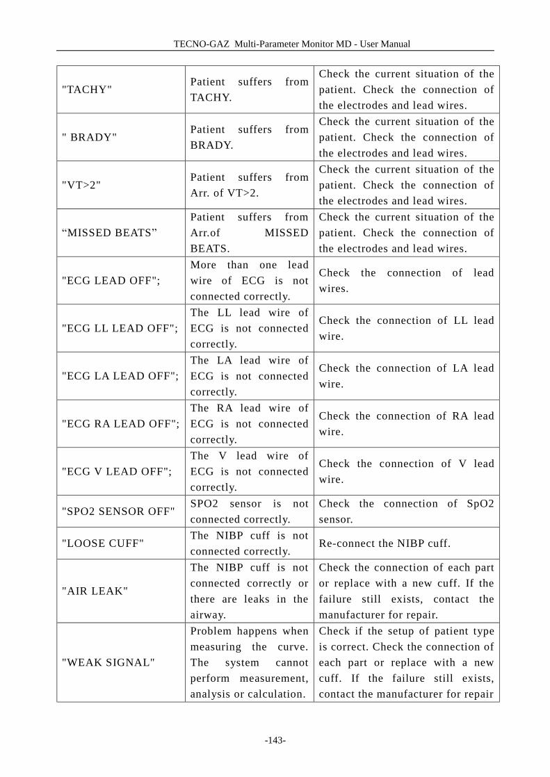
TECNO-GAZ Multi-Parameter Monitor MD - User Manual
-143-
"TACHY" Patient suffers from TACHY.
Check the current situation of the patient. Check the connection of the electrodes and lead wires.
" BRADY" Patient suffers from BRADY.
Check the current situation of the patient. Check the connection of the electrodes and lead wires.
"VT>2" Patient suffers from Arr. of VT>2.
Check the current situation of the patient. Check the connection of the electrodes and lead wires.
“MISSED BEATS” Patient suffers from Arr.of MISSED BEATS.
Check the current situation of the patient. Check the connection of the electrodes and lead wires.
"ECG LEAD OFF"; More than one lead wire of ECG is not connected correctly.
Check the connection of lead wires.
"ECG LL LEAD OFF"; The LL lead wire of ECG is not connected correctly.
Check the connection of LL lead wire.
"ECG LA LEAD OFF"; The LA lead wire of ECG is not connected correctly.
Check the connection of LA lead wire.
"ECG RA LEAD OFF"; The RA lead wire of ECG is not connected correctly.
Check the connection of RA lead wire.
"ECG V LEAD OFF"; The V lead wire of ECG is not connected correctly.
Check the connection of V lead wire.
"SPO2 SENSOR OFF" SPO2 sensor is not connected correctly.
Check the connection of SpO2 sensor.
"LOOSE CUFF" The NIBP cuff is not connected correctly.
Re-connect the NIBP cuff.
"AIR LEAK"
The NIBP cuff is not connected correctly or there are leaks in the airway.
Check the connection of each part or replace with a new cuff. If the failure still exists, contact the manufacturer for repair.
"WEAK SIGNAL"
Problem happens when measuring the curve. The system cannot perform measurement, analysis or calculation.
Check if the setup of patient type is correct. Check the connection of each part or replace with a new cuff. If the failure still exists, contact the manufacturer for repair
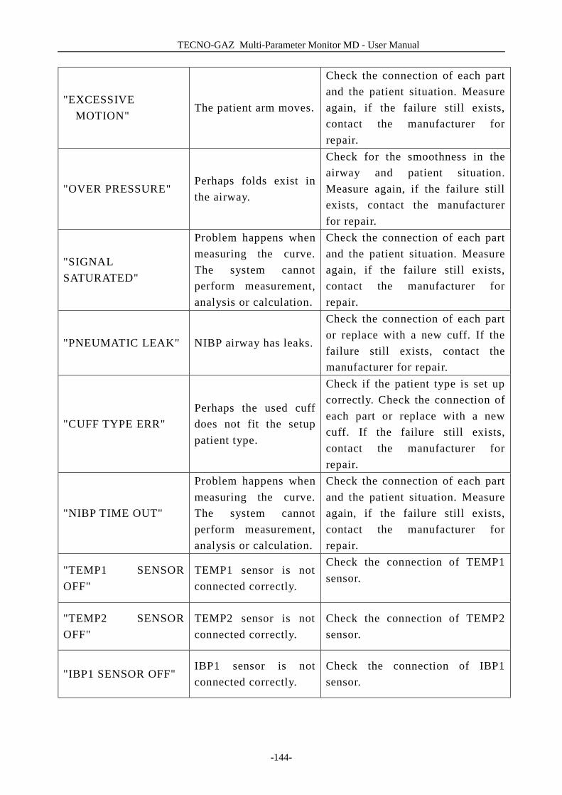
TECNO-GAZ Multi-Parameter Monitor MD - User Manual
-144-
"EXCESSIVE MOTION"
The patient arm moves.
Check the connection of each part and the patient situation. Measure again, if the failure still exists, contact the manufacturer for repair.
"OVER PRESSURE" Perhaps folds exist in the airway.
Check for the smoothness in the airway and patient situation. Measure again, if the failure still exists, contact the manufacturer for repair.
"SIGNAL SATURATED"
Problem happens when measuring the curve. The system cannot perform measurement, analysis or calculation.
Check the connection of each part and the patient situation. Measure again, if the failure still exists, contact the manufacturer for repair.
"PNEUMATIC LEAK" NIBP airway has leaks.
Check the connection of each part or replace with a new cuff. If the failure still exists, contact the manufacturer for repair.
"CUFF TYPE ERR" Perhaps the used cuff does not fit the setup patient type.
Check if the patient type is set up correctly. Check the connection of each part or replace with a new cuff. If the failure still exists, contact the manufacturer for repair.
"NIBP TIME OUT"
Problem happens when measuring the curve. The system cannot perform measurement, analysis or calculation.
Check the connection of each part and the patient situation. Measure again, if the failure still exists, contact the manufacturer for repair.
"TEMP1 SENSOR OFF"
TEMP1 sensor is not connected correctly.
Check the connection of TEMP1 sensor.
"TEMP2 SENSOR OFF"
TEMP2 sensor is not connected correctly.
Check the connection of TEMP2 sensor.
"IBP1 SENSOR OFF" IBP1 sensor is not connected correctly.
Check the connection of IBP1 sensor.

TECNO-GAZ Multi-Parameter Monitor MD - User Manual
-145-
"IBP2 SENSOR OFF" IBP2 sensor is not connected correctly.
Check the connection of IBP2 sensor.
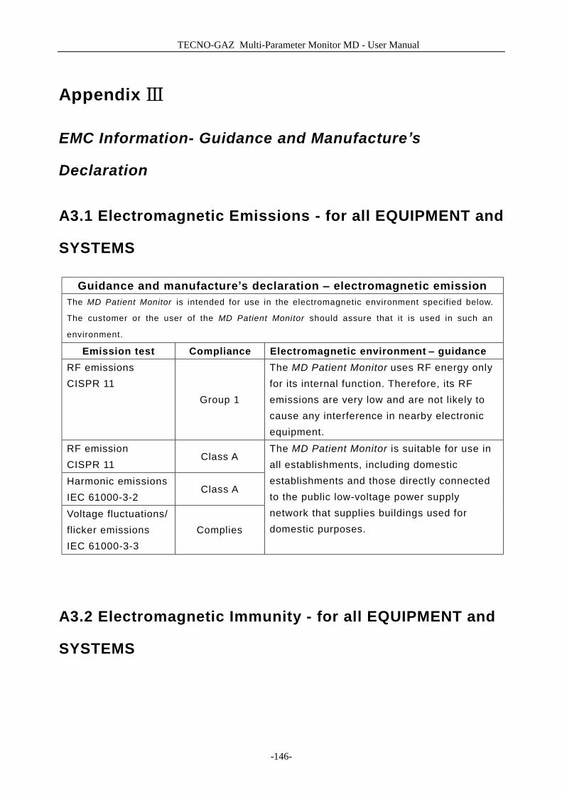
TECNO-GAZ Multi-Parameter Monitor MD - User Manual
-146-
Appendix Ⅲ
EMC Information- Guidance and Manufacture’s
Declaration
A3.1 Electromagnetic Emissions - for all EQUIPMENT and
SYSTEMS
Guidance and manufacture’s declaration – electromagnetic emission The MD Patient Monitor is intended for use in the electromagnetic environment specified below.
The customer or the user of the MD Patient Monitor should assure that it is used in such an
environment.
Emission test Compliance Electromagnetic environment – guidance RF emissions CISPR 11
Group 1
The MD Patient Monitor uses RF energy only for its internal function. Therefore, its RF emissions are very low and are not likely to cause any interference in nearby electronic equipment.
RF emission CISPR 11
Class A
Harmonic emissions IEC 61000-3-2
Class A
Voltage fluctuations/ flicker emissions IEC 61000-3-3
Complies
The MD Patient Monitor is suitable for use in all establishments, including domestic establishments and those directly connected to the public low-voltage power supply network that supplies buildings used for domestic purposes.
A3.2 Electromagnetic Immunity - for all EQUIPMENT and
SYSTEMS

TECNO-GAZ Multi-Parameter Monitor MD - User Manual
-147-
Guidance and manufacture’s declaration – electromagnetic immunity The MD Patient Monitor is intended for use in the electromagnetic environment specified below. The
customer or the user of MD Patient Monitor should assure that it is used in such an environment.
Immunity test IEC 60601 test
level Compliance level
Electromagnetic environment -
guidance Electrostatic discharge (ESD) IEC 61000-4-2
±6 kV contact ±8 kV air
±6 kV contact ±8 kV air
Floors should be wood, concrete or ceramic tile. If floor are covered with synthetic material, the relative humidity should be at least 30%.
Electrical fast transient/burst IEC 61000-4-4
±2 kV for power supply lines
±1kV for power supply lines
Mains power quality should be that of a typical commercial or hospital environment.
Surge IEC 61000-4-5
±1 kV differential mode ±2 kV common mode
±1 kV differential mode ±2 kV common mode
Mains power quality should be that of a typical commercial or hospital environment.
Power frequency (50/60Hz) magnetic field IEC61000-4-8
3A/m 3A/m Power frequency magnetic fields should be at levels characteristic of a typical location in a typical commercial or hospital environment.
Voltage dips, short interruptions and voltage variations on power supply input lines IEC 61000-4-11
<5% UT (>95% dip in UT) for 0.5 cycle 40% UT (60% dip in UT) for 5 cycles 70% UT (30% dip in UT) for 25 cycles
<5% UT (>95% dip in UT) for 0.5 cycle 40% UT (60% dip in UT) for 5 cycles 70% UT (30% dip in UT) for 25 cycles
Mains power quality should be that of a typical commercial or hospital environment. If the user of the MD Patient Monitor requires continued operation during power mains interruptions, it is recommended that the MD Patient Monitor be powered from an
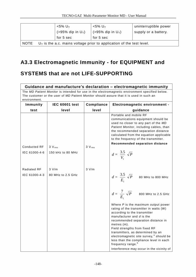
TECNO-GAZ Multi-Parameter Monitor MD - User Manual
-148-
<5% UT (>95% dip in UT) for 5 sec
<5% UT (>95% dip in UT) for 5 sec
uninterruptible power supply or a battery.
NOTE UT is the a.c. mains voltage prior to application of the test level.
A3.3 Electromagnetic Immunity - for EQUIPMENT and
SYSTEMS that are not LIFE-SUPPORTING
Guidance and manufacture’s declaration – electromagnetic immunity The MD Patient Monitor is intended for use in the electromagnetic environment specified below. The customer or the user of MD Patient Monitor should assure that it is used in such an environment.
Immunity test
IEC 60601 test level
Compliance level
Electromagnetic environment - guidance
Conducted RF
IEC 61000-4-6
Radiated RF
IEC 61000-4-3
3 Vrms
150 kHz to 80 MHz
3 V/m
80 MHz to 2.5 GHz
3 V rms
3 V/m
Portable and mobile RF communications equipment should be used no closer to any part of the MD Patient Monitor , including cables, than the recommended separation distance calculated from the equation applicable to the frequency of the transmitter. Recommended separation distance
PV
d
=
1
5.3
PE
d
=
1
5.3 80 MHz to 800 MHz
PE
d
=
1
7 800 MHz to 2.5 GHz
Where P is the maximum output power rating of the transmitter in watts (W) according to the transmitter manufacturer and d is the recommended separation distance in metres (m). Field strengths from fixed RF transmitters, as determined by an electromagnetic site survey, a should be less than the compliance level in each frequency range.b Interference may occur in the vicinity of
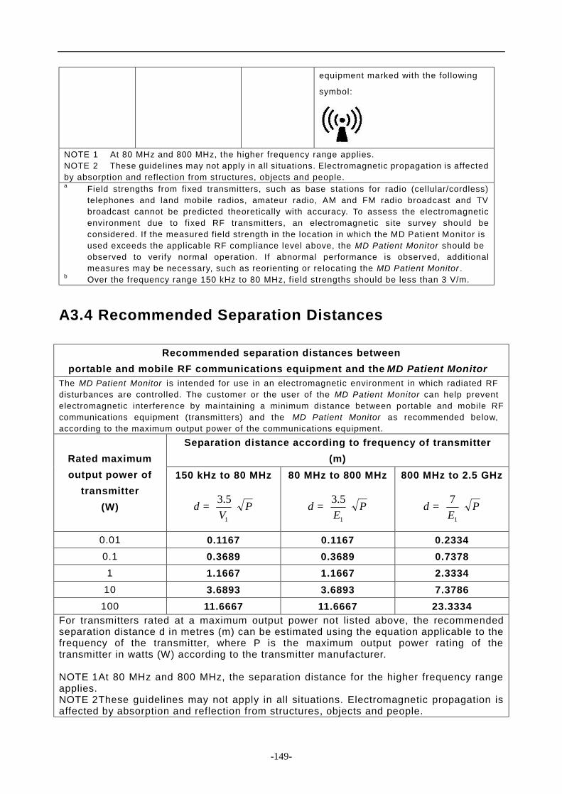
-149-
equipment marked with the following
symbol:
NOTE 1 At 80 MHz and 800 MHz, the higher frequency range applies. NOTE 2 These guidelines may not apply in all situations. Electromagnetic propagation is affected by absorption and reflection from structures, objects and people. a Field strengths from fixed transmitters, such as base stations for radio (cellular/cordless)
telephones and land mobile radios, amateur radio, AM and FM radio broadcast and TV broadcast cannot be predicted theoretically with accuracy. To assess the electromagnetic environment due to fixed RF transmitters, an electromagnetic site survey should be considered. If the measured field strength in the location in which the MD Patient Monitor is used exceeds the applicable RF compliance level above, the MD Patient Monitor should be observed to verify normal operation. If abnormal performance is observed, additional measures may be necessary, such as reorienting or relocating the MD Patient Monitor .
b Over the frequency range 150 kHz to 80 MHz, f ield strengths should be less than 3 V/m.
A3.4 Recommended Separation Distances
Recommended separation distances between portable and mobile RF communications equipment and the MD Patient Monitor
The MD Patient Monitor is intended for use in an electromagnetic environment in which radiated RF disturbances are controlled. The customer or the user of the MD Patient Monitor can help prevent electromagnetic interference by maintaining a minimum distance between portable and mobile RF communications equipment (transmitters) and the MD Patient Monitor as recommended below, according to the maximum output power of the communications equipment.
Separation distance according to frequency of transmitter (m)
Rated maximum output power of
transmitter (W)
150 kHz to 80 MHz
PV
d
=
1
5.3
80 MHz to 800 MHz
PE
d
=
1
5.3
800 MHz to 2.5 GHz
PE
d
=
1
7
0.01 0.1167 0.1167 0.2334 0.1 0.3689 0.3689 0.7378 1 1.1667 1.1667 2.3334
10 3.6893 3.6893 7.3786 100 11.6667 11.6667 23.3334
For transmitters rated at a maximum output power not listed above, the recommended separation distance d in metres (m) can be estimated using the equation applicable to the frequency of the transmitter, where P is the maximum output power rating of the transmitter in watts (W) according to the transmitter manufacturer. NOTE 1 At 80 MHz and 800 MHz, the separation distance for the higher frequency range applies. NOTE 2 These guidelines may not apply in all situations. Electromagnetic propagation is affected by absorption and reflection from structures, objects and people.
d e n t a l a n d m e d i c a l e q u i p m e n t
TECNOTECNOTECNOTECNO----GAZ S.p.A.GAZ S.p.A.GAZ S.p.A.GAZ S.p.A. Strada Cavalli,4 • 43038 • Sala Baganza • Parma • ITALIA Tel. +39 0521 83.39.26 r.a. Fax. +39 0521 83.33.91
www.tecnogaz.comwww.tecnogaz.comwww.tecnogaz.comwww.tecnogaz.com
This manual must always be kept with the product, in complying with the Directives of European Community.
TECNO-GAZ reserves the right to modify the enclosed document without notice.
TECNO-GAZ reserves the property of the document and forbids others to use it or spread it without its approval.