multi-user interactions for spatially augmented reality games
TRANSCRIPT
MULTI-USER INTERACTIONS FOR SPATIALLYAUGMENTED REALITY GAMES
By
Andrew Dolce
A Thesis Submitted to the Graduate
Faculty of Rensselaer Polytechnic Institute
in Partial Fulfillment of the
Requirements for the Degree of
MASTER OF SCIENCE
Major Subject: COMPUTER SCIENCE
Approved:
Barbara Cutler, Thesis Adviser
Rensselaer Polytechnic InstituteTroy, New York
April 2011(For Graduation May 2011)
CONTENTS
LIST OF FIGURES . . . . . . . . . . . . . . . . . . . . . . . . . . . . . . . . iv
ACKNOWLEDGMENT . . . . . . . . . . . . . . . . . . . . . . . . . . . . . . v
ABSTRACT . . . . . . . . . . . . . . . . . . . . . . . . . . . . . . . . . . . . vi
1. INTRODUCTION . . . . . . . . . . . . . . . . . . . . . . . . . . . . . . . 1
1.1 Augmented Reality . . . . . . . . . . . . . . . . . . . . . . . . . . . . 1
1.2 Tabletop Games . . . . . . . . . . . . . . . . . . . . . . . . . . . . . . 2
1.3 Video Games . . . . . . . . . . . . . . . . . . . . . . . . . . . . . . . 3
1.4 Motivation and Goals . . . . . . . . . . . . . . . . . . . . . . . . . . . 4
2. RELATED WORK . . . . . . . . . . . . . . . . . . . . . . . . . . . . . . . 6
2.1 Display Types . . . . . . . . . . . . . . . . . . . . . . . . . . . . . . . 6
2.1.1 Head-mounted Displays . . . . . . . . . . . . . . . . . . . . . 6
2.1.2 Hand-held Displays . . . . . . . . . . . . . . . . . . . . . . . . 7
2.1.3 Spatially Aligned Displays . . . . . . . . . . . . . . . . . . . . 8
2.2 3D Registration . . . . . . . . . . . . . . . . . . . . . . . . . . . . . . 11
2.2.1 Calibration . . . . . . . . . . . . . . . . . . . . . . . . . . . . 11
2.2.2 Tracking . . . . . . . . . . . . . . . . . . . . . . . . . . . . . . 12
2.2.2.1 Fiducial Markers . . . . . . . . . . . . . . . . . . . . 12
2.2.2.2 Structured Light . . . . . . . . . . . . . . . . . . . . 13
2.2.2.3 Imperceptible Pattern Embedding . . . . . . . . . . 14
2.2.2.4 Infrared Tracking . . . . . . . . . . . . . . . . . . . . 15
2.2.2.5 Color-based Tracking . . . . . . . . . . . . . . . . . . 16
2.2.2.6 Human Tracking . . . . . . . . . . . . . . . . . . . . 16
2.3 Summary . . . . . . . . . . . . . . . . . . . . . . . . . . . . . . . . . 17
3. SAR GAME APPLICATIONS . . . . . . . . . . . . . . . . . . . . . . . . . 18
3.1 ARmy Simulation Overview . . . . . . . . . . . . . . . . . . . . . . . 18
3.1.1 Terrain Placement . . . . . . . . . . . . . . . . . . . . . . . . 20
3.1.2 Army Placement . . . . . . . . . . . . . . . . . . . . . . . . . 23
3.1.3 Movement Phase . . . . . . . . . . . . . . . . . . . . . . . . . 23
3.1.4 Combat Simulation . . . . . . . . . . . . . . . . . . . . . . . . 24
ii
3.2 Large-scale Applications . . . . . . . . . . . . . . . . . . . . . . . . . 27
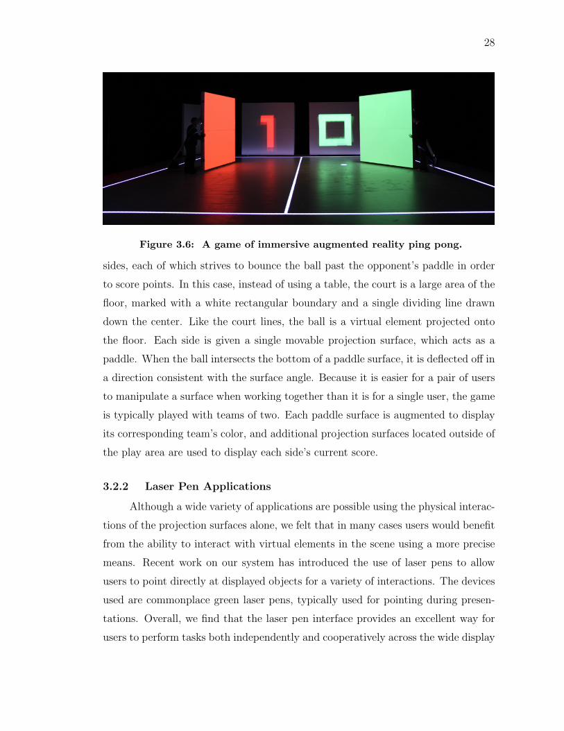
3.2.1 Ping Pong . . . . . . . . . . . . . . . . . . . . . . . . . . . . 27
3.2.2 Laser Pen Applications . . . . . . . . . . . . . . . . . . . . . 28
3.3 Summary . . . . . . . . . . . . . . . . . . . . . . . . . . . . . . . . . 29
4. IMPLEMENTATION DETAILS . . . . . . . . . . . . . . . . . . . . . . . 31
4.1 System Overview . . . . . . . . . . . . . . . . . . . . . . . . . . . . . 31
4.1.1 Camera Component for Scene Recognition and Tracking . . . 31
4.1.2 Vision Component . . . . . . . . . . . . . . . . . . . . . . . . 32
4.1.3 World Modeling Component . . . . . . . . . . . . . . . . . . 33
4.1.4 Display Controller and Projector Renderers . . . . . . . . . . 33
4.2 ARmy Application Details . . . . . . . . . . . . . . . . . . . . . . . . 33
4.2.1 Object Detection . . . . . . . . . . . . . . . . . . . . . . . . . 34
4.2.2 Modeling the Game World . . . . . . . . . . . . . . . . . . . 36
4.2.3 Tracking Soldier Movement . . . . . . . . . . . . . . . . . . . 39
4.2.4 Line of Sight Calculation . . . . . . . . . . . . . . . . . . . . 41
4.2.5 Visual Augmentation . . . . . . . . . . . . . . . . . . . . . . 41
4.3 Large-scale Application Details . . . . . . . . . . . . . . . . . . . . . 42
4.3.1 Infrared Point Detection . . . . . . . . . . . . . . . . . . . . . 43
4.3.2 Surface Recognition and Tracking . . . . . . . . . . . . . . . . 43
4.3.3 Laser Pen Detection . . . . . . . . . . . . . . . . . . . . . . . 48
4.4 Summary . . . . . . . . . . . . . . . . . . . . . . . . . . . . . . . . . 48
5. DISCUSSION AND FUTURE WORK . . . . . . . . . . . . . . . . . . . . 49
5.1 Simultaneous Acquisition and Display . . . . . . . . . . . . . . . . . . 49
5.2 Improvements to Object Identification . . . . . . . . . . . . . . . . . 50
5.3 Additional User Interactions . . . . . . . . . . . . . . . . . . . . . . 51
5.4 Audio Features . . . . . . . . . . . . . . . . . . . . . . . . . . . . . . 51
6. CONCLUSIONS . . . . . . . . . . . . . . . . . . . . . . . . . . . . . . . . 53
LITERATURE CITED . . . . . . . . . . . . . . . . . . . . . . . . . . . . . . 54
iii
LIST OF FIGURES
1.1 Images of ARmy: A Spatially Augmented Reality Game . . . . . . . . . 5
2.1 Projector/Camera Rig . . . . . . . . . . . . . . . . . . . . . . . . . . . 11
3.1 ARmy Application State Diagram . . . . . . . . . . . . . . . . . . . . . 19
3.2 ARmy Primitives . . . . . . . . . . . . . . . . . . . . . . . . . . . . . . 21
3.3 Terrain Placement . . . . . . . . . . . . . . . . . . . . . . . . . . . . . . 22
3.4 Movement Region Display . . . . . . . . . . . . . . . . . . . . . . . . . 24
3.5 Sample ARmy Game . . . . . . . . . . . . . . . . . . . . . . . . . . . . 25
3.6 Spatially Augmented Ping Pong Game . . . . . . . . . . . . . . . . . . 28
3.7 Spatially Augmented Shooting Gallery Game . . . . . . . . . . . . . . . 29
4.1 Overview of System Architecture . . . . . . . . . . . . . . . . . . . . . . 32
4.2 ARmy Object Detection . . . . . . . . . . . . . . . . . . . . . . . . . . 35
4.3 ARmy Game World Model . . . . . . . . . . . . . . . . . . . . . . . . . 38
4.4 Assignment of Material Properties . . . . . . . . . . . . . . . . . . . . . 42
4.5 Surface Recognition and Tracking . . . . . . . . . . . . . . . . . . . . . 43
4.6 Large-Scale Surface Recognition Algorithm . . . . . . . . . . . . . . . . 44
4.7 Optimal Surface Configuration Search . . . . . . . . . . . . . . . . . . . 46
iv

ACKNOWLEDGMENT
First and foremost, I am sincerely grateful to my adviser, Dr. Barbara Cutler, who
has been a wonderful mentor to me throughout my time at RPI. I thank her for
welcoming me into her research group, for encouraging my ideas (even the ones
bordering on whimsical,) and for showing up in lab with donuts exactly when they
are most needed. Without her patience and support, this thesis would not exist.
My research is but a small part of a much larger body of work, and I would
like to thank all of my fellow contributors, including Dr. Yu Sheng, Josh Nasman,
Eric Li, and Ted Yapo. Working on our system has been a truly intense experience
full of long hours, dark rooms, and faulty projectors, but I can honestly say that
it has been a pleasure collaborating with each of these people and I wish them the
best in their future endeavors.
I also thank my labmates, Chris Stuetzle, Eric Smith, Zhongxian Chen, Her-
bert Holzbauer, Justin LaPre, and Mark Anderson, for all the conversations that
make our lab a fun place to work. I owe special thanks to Chris, who I hold re-
sponsible for transforming me into a board game geek. I would also like to thank
all of my friends at RPI, especially my roommates, Eric Li, Jeff Bedard, and Pat
McKenna, who made every year of my college life an absolute blast.
Last but certainly not least, I thank my family, especially my parents, Stephen
and Maria, and my younger brother, Joseph, as well as my grandparents, aunts,
uncles, and all of my cousins, for giving me the love and support that made me
grow into who I am today.
v
ABSTRACT
Augmented reality offers a means of overlaying interactive virtual elements onto
real world environments. Motivated by an interest in developing new methods for
multi-user interactions in the context of games, this thesis extends an existing spa-
tially augmented reality system to develop a number of engaging game prototypes
in both small-scale and human-scale display environments. Primarily, it discusses
the details of ARmy, a two-player military strategy game that demonstrates the
concept of combining physical tabletop games with virtual elements characteristic
of modern video games. As players move plastic miniatures through a physical
scene, the application moderates and augments play by maintaining a heightfield
representation of the scene, which it uses to validate movement paths and perform
automatic line-of-sight calculations.
The described applications are built on top of a display system capable of
dynamically augmenting the appearance of physical objects. The system uses an
overhead camera to track a collection of movable, white surfaces, and applies virtual
textures to these objects using multiple projectors. This thesis includes a high-level
overview of the system architecture, and describes some of the specific methods it
uses, most notably in regard to the problem of fast 3D registration of surface objects.
Finally, it discusses the effectiveness of the applications in their current form, as well
as possible areas for future research.
vi
1. INTRODUCTION
1.1 Augmented Reality
The term virtual reality (VR) refers to any visualization that replaces the
user’s view of the real world with computer-generated visuals. In other words,
virtual reality strives to create the illusion that the user is fully immersed in a virtual
world. Suppose instead that we aim not to completely remove the user’s sense of the
real world, but rather to augment it by overlaying or otherwise blending in virtual
elements and information. This concept, known as augmented reality (AR), entails
a variety of exciting possibilities.
Unlike VR, which primarily allows us to interact with entities that are not real,
AR holds the promise of taking the physical, real-world interactions that we expe-
rience every day and improving upon them. For example, AR techniques could be
used to overlay useful information onto physical objects, such as combining medical
data with a surgeon’s real-world view of a patient’s body, or annotating products in
a grocery store with calories and sales information.
The AR techniques that exist today run a wide gambit, varying significantly
in both the details of implementation and the user experience provided by the end
result. For this reason, deciding on a precise definition for AR can be difficult.
However, a generally accepted definition is presented by Azuma [4], which states that
an AR system must satisfy three basic characteristics as follows. First, the system
must combine real and virtual elements. Second, the system must be interactive,
responding promptly to user actions. Finally, the system must be registered in 3D,
meaning that the virtual elements must exhibit some degree of alignment with the
physical scene. Combining these three properties, we see that augmented reality
aims not only to display virtual entities, but to create the appearance that these
elements are temporally and spatially consistent with the real environment.
In exploration of AR techniques, our research group has developed a system
capable of dynamically projecting virtual images onto movable physical objects. Our
method is an example of spatially augmented reality, a term coined by Bimber and
1
2
Raskar [6] to describe AR systems where the display technology consists of devices
embedded in the environment. Originally developed with the specific intention of
creating a flexible architectural design tool, our system has since been expanded to
include a variety of other applications. Of the wide range of possibilities, one that
I find personally intriguing is the development of augmented reality games.
Games are found throughout every day life in a variety of forms, and can be
a source of entertainment, a means for education, and even a medium for artistic
expression or social commentary. Of the numerous types of games that exist, two
categories that are particularly interesting in regard to AR research are physical
tabletop games, which use tangible game elements, and video games, which leverage
modern computing technology to create virtual user experiences.
1.2 Tabletop Games
The term “tabletop game” can be used to describe a wide variety of games.
Popular examples include board games, such as chess, Monopoly [9], The Settlers of
Catan [36], and Puerto Rico [32], card games, such as Magic: The Gathering [11],
pen-and-paper role-playing games, such as Dungeons & Dragons [12], and many
others. Of particular interest in the context of augmented reality are “miniature war
games,” such as Warhammer 40,000 [26] and Mage Knight [41], which use realistic
figurines and other models to create a highly-detailed, miniature game world.
Despite the diversity of these games, they do share a number of defining char-
acteristics. One such property is the use of some combination of physical, tangible
game objects, such as a board, deck of cards, dice, or miniature figurines. A ma-
jor advantage of this physical tangibility is that it usually provides a simple and
intuitive interface. In other words, although the rules of a particular game may
be complex, the basic actions governed by the rules typically boil down to sim-
ple physical operations, such as moving a game piece, rolling dice, or drawing a
card. Additionally, because tabletop games are usually played in a single, physical
location, they provide a social setting for personal, face-to-face interactions.
Though they define a set of rules and provide necessary game objects, tabletop
games do not offer any autonomous agents for moderating or facilitating play. In
3
other words, the progression of play is typically governed completely by the players,
who are collectively responsible for correctly keeping track of the state of the game
and for making sure that everyone is following the rules. For example, in Monopoly,
players keep track of money using paper bills and manually resolve the payment
of debts. Although a well designed game may provide a set of helpful procedures
or other mechanisms to keep players on track, some players may find bookkeeping
tasks to be overly taxing, particularly in cases where the rules of the game are highly
complex.
1.3 Video Games
In contrast, video games allow the players to interact in ways that are purely
virtual. The game world is a simulation, the state of which is displayed to the
user in the form of a rendered image, sometimes accompanied with fantastic visuals
generated through computer graphics and art techniques. Traditionally, the player
interacts with the world using some configuration of input devices, such as a mouse
and keyboard, or a hand-held game controller equipped with buttons.
The result of these implementational differences is that video games offer a
drastically different experience than tabletop games. One significant advantage of
video games is that they provide a game world that is essentially autonomous. Play-
ers are no longer responsible for governing over the state of the game. Instead, they
simply provide input to indicate their desired actions, and the game itself decides
upon the result, allowing for the creation of larger and more complex simulations.
For example, the virtual world of a game might contain a simulated city, inhabited
by a large population of people who each carry out a series of individual actions
and decisions. Clearly a finely detailed, large-scale simulation such as this would be
impractical to achieve in the form of a physical tabletop game, which would require
the players to manually maintain each member of the population.
Creating an appealing virtual world is pointless unless the players are provided
with an effective means of interaction. Unfortunately, in this regard video games
often fall short of tabletop games, in that many video games lack a natural, intuitive
interface. Although veteran gamers typically have no problem utilizing a mouse,
4
keyboard, or console controller, novice and casual players often find such devices
alienating, a problem that has driven recent industry trends toward the development
of more intuitive interfaces.
1.4 Motivation and Goals
In considering the differences between tabletop games and video games, an
intriguing idea is the possibility of combining the two into an interesting new type
of game. More specifically, by using a physically manifested, tabletop game as
a foundation, and utilizing AR techniques, one could introduce a computational
module to moderate the game and to augment the physical appearance of the game
by overlaying virtual elements. The ideal result would be a hybrid game experience,
combining the intuitive, tangible interfaces and face-to-face player interactions of a
tabletop game with the highly detailed world and rich computer graphics of a video
game. This concept serves as the primary motivation for my research.
The purpose of this thesis is to summarize my work in developing spatially
augmented reality applications to facilitate multi-user game interactions in both
small-scale tabletop settings and large-scale immersive environments. In particular,
I focus on ARmy, a proof-of-concept game prototype that borrows concepts from
traditional tabletop war games and augments them with virtual elements, as shown
in Figure 1.1. I also present a number of applications demonstrating possible ideas
for AR games using various devices for interaction in human-scale display environ-
ments. Additionally, I describe my contributions to some of the underlying system
components that make these applications possible. Finally, I discuss the preliminary
results of the applications, as well as aspects that could be expanded through future
work.
5
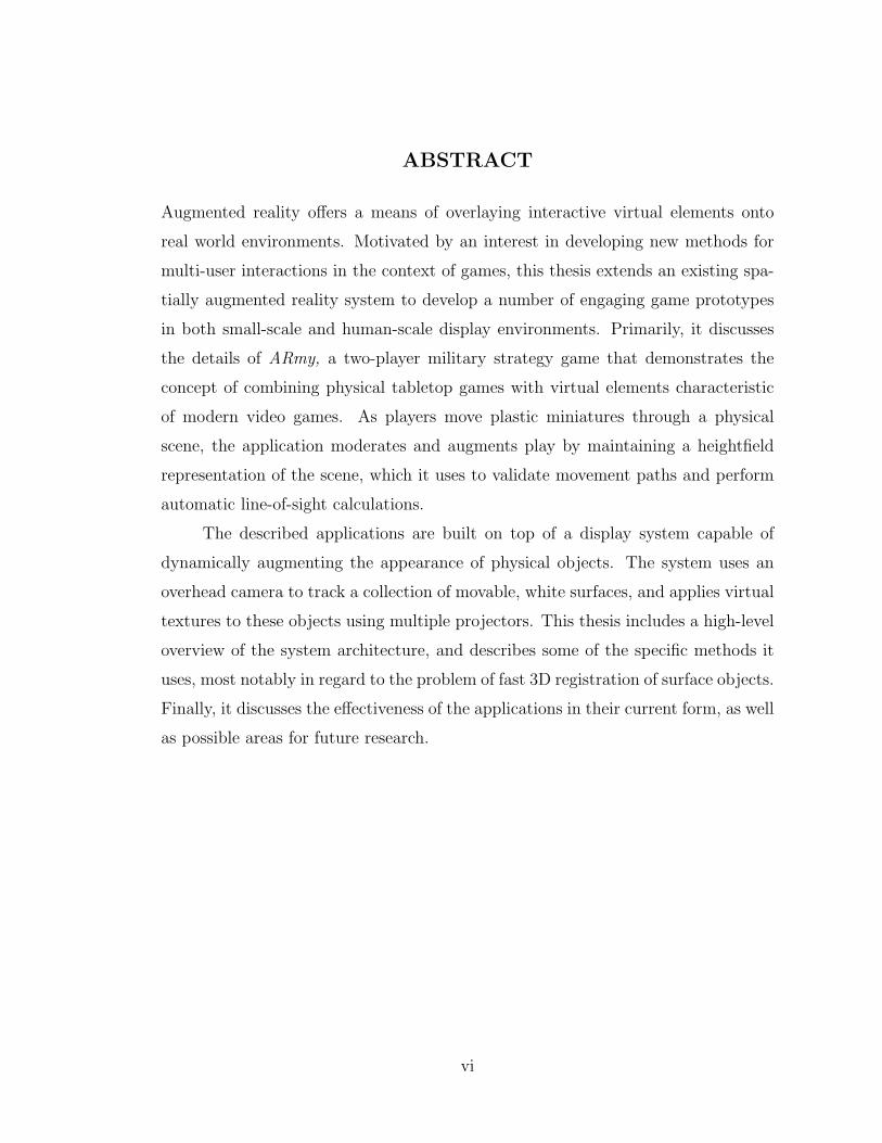
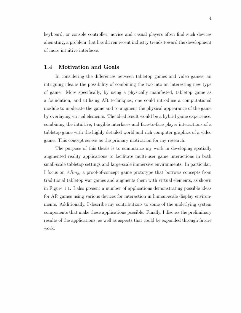
Figure 1.1: The above images are snapshots of the ARmy application inprogress. The application is an example of a spatially augmented realitygame, which combines physical game objects with virtual elements throughprojection. The projections decorate simple, white objects with colorful vir-tual textures, and display important game information regarding legal movesand simulated combat.
2. RELATED WORK
Augmented reality is a relatively recent field, with a large amount of research fo-
cusing on how to combine underlying technologies to achieve stable, reproducible
systems. Existing work includes a diverse set of techniques, of which spatially aug-
mented reality comprises only a small subset. In order to comprehend the relative
advantages and disadvantages of our techniques, it is useful to gain some high level
understanding of this broad body of work. The purpose of this chapter is to describe
and compare a number of common AR techniques and to provide relevant exam-
ples. The discussion focuses in particular on two important problems that must be
solved in order to achieve Azuma’s definition of augmented reality: the creation of
an effective augmented display, and the problem of 3D registration.
2.1 Display Types
One major component of any AR system is the display technology used to visu-
ally integrate the virtual elements with the real world. A wide variety of technologies
have been explored by previous research in both augmented and virtual reality, and
classifying them can be a challenging task. For the purpose of enumerating some im-
portant examples, I adopt the classification scheme of Bimber and Raskar [6], which
separates display technologies into three main groups: head-mounted, hand-held,
and spatially aligned.
2.1.1 Head-mounted Displays
Head-mounted displays (HMDs) comprise the earliest and most dominant dis-
play technology used in augmented reality applications. As their name implies,
head-mounted displays are devices physically worn by the user, generally composed
of some eye-aligned viewing equipment that provides the augmented visuals. The
earliest and most typical HMDs can be classified as optical or video-based see-
through displays, although more recent research has also explored head-mounted
projectors, and retinal display methods.
6
7
The first head-mounted display, and therefore the earliest example of aug-
mented reality, is credited to Ivan E. Sutherland [35], who developed an opti-
cal see-through display to present the viewer with perspective images of three-
dimensional, virtual, wireframe objects. An optical see-through display is one in
which the user looks through an optical combiner, such as a partially transparent
mirror. The combiner allows some light to pass through while simultaneously re-
flecting computer-generated images into the viewer’s eyes, thus combining real and
virtual images. In contrast, a video-based augmented display provides a view of the
physical world through video footage. Images are captured via camera and com-
bined in real time with computer-generated visuals before being displayed on some
form of head-mounted monitor. Numerous survey papers exist which compare and
contrast optical and video-based HMDs [4, 30].
In general, head-mounted displays are cited as being good candidates for
portable AR applications in that they equip users with personal display devices
that could be worn in a variety of settings. However, they also suffer from a number
of disadvantages. Because HMDs typically rely on small, eye-aligned displays, they
tend to be limited in both display resolution and field of view. Bimber and Raskar
note that the hardware required for many head-mounted devices may be expensive
to construct, difficult to properly calibrate, and at times too heavy for users to wear
comfortably [6].
2.1.2 Hand-held Displays
In contrast to head-mounted displays, hand-held displays are those in which
the display technology is embedded in small, portable, hand-held devices. Gener-
ally, hand-held AR systems aim to use the portable devices already available to the
average consumer today, including cell phones, personal digital assistants (PDAs),
and laptop PCs. Such devices already contain small monitor or touch-screen dis-
plays, as well as digital cameras, which make them viable candidates for video-based
see-through AR techniques. Most importantly, these devices represent technology
that has already become ubiquitous, providing an immediate platform for AR ap-
plications for everyday use.
8
A potential limitation of hand-held AR applications is that many mobile de-
vices lack the computational power and resources of larger systems. One solution is
to develop applications as lightweight clients that offload heavy computations onto
remote servers, such as in the work of Pasman and Woodward [24], who developed
a client/server framework for AR applications on a PDA using data compression
schemes for fast network traffic. Wagner and Schmalsteig [38] presented an AR im-
plementation for an off-the-shelf PDA capable of running in both a self-contained
stand-alone mode and a distributed networked mode. Their system switches be-
tween the two methods dynamically to adapt to variable network availability.
Hand-held AR techniques are beginning to find prominence within the video
game industry. Perhaps the most notable example is the Nintendo 3DS, a hand-held
video game system equipped with multiple cameras and an autostereoscopic screen,
allowing for video see-through techniques to be combined with 3D effects [22]. The
system comes with a library of AR games, which can be played by aiming the camera
at a set of provided marker cards. A similar example is ARhrrrr!, an AR game
developed by Georgia Tech Augmented Environments Lab and the Savannah College
of Art and Design, which also uses a mobile device as a video see-through display [2].
The game overlays graphics onto a physical paper map, and also incorporates other
tangible objects, such as brightly colored candies.
2.1.3 Spatially Aligned Displays
The third and final category of AR display devices is characterized by dis-
plays that are completely unattached to the user, but instead consist of fixtures
physically aligned with the environment. These spatially augmented reality (SAR)
techniques represent the particular branch of AR under which our current research
falls. Some spatial displays apply optical or video-based see-through techniques by
using stationary screens or monitors to display the augmented visuals. For example,
Bimber et al. present a “Virtual Showcase,” which uses half-silvered mirror com-
biners to create an enclosed AR display analogous to the physical showcases typical
of museum exhibits [5]. However, the spatial display techniques most related to our
research are those which employ direct augmentation, typically by displaying virtual
9
information directly on the surfaces of physical objects using some configuration of
video projectors.
An important and well-known example of projector-based spatial display tech-
niques is the CAVE (CAVE Automatic Virtual Environment) system developed by
Cruz-Neira et. al [8]. Although the CAVE is technically classified as an example of
virtual reality, it stands as a significant precursor to SAR techniques. The display
area is an enclosed room comprised of rear-projection screens and a top-down pro-
jector for displaying images on the floor, thus allowing for an effective immersive
environment. The user is equipped with head-tracking devices and 3D goggles for
stereoscopic image display.
Raskar and colleagues have presented the “Office of the Future,” which ex-
plores the possibility of using SAR applications in the setting of an everyday workspace
to facilitate telepresence and computing tasks [29]. They proposed using multiple
projectors to present images on irregular, nonplanar surfaces, and demonstrated a
technique for generating images suitable for such displays [27]. Their later work
expands upon these techniques with the idea of “Shader Lamps”, which allow for
augmentation of complex 3D objects to create the appearance of desired material
properties, such as color and texture [28].
A significant underlying theme of much projection-based SAR research is the
vision of a future in which these display technologies have become truly ubiquitous.
Underkoffler et al. presented the idea of a “Luminous Room,” lit by multiple “IO
bulbs,” which combine a projector and camera to facilitate both spatial display and
user interactions [37]. Pinhanez proposed the use of “Everywhere Display” projec-
tors equipped with poseable mirrors that allow for the projection to be steered to
any suitable surface within the surrounding environment [25]. The idea behind each
of these techniques is to create a compact SAR device that can be reasonably re-
produced and distributed for use in homes, workplaces, schools, commercial venues,
and other public settings.
Spatially augmented reality techniques offer a number of advantages over user-
attached display technologies. One benefit is that SAR displays are capable of
covering large surfaces in full-scale, immersive environments, and therefore provide
10
higher resolution displays with a wider field of view. With the exception of specific
view-dependent effects, general augmentation of a scene can be experienced by any
number of users independent of the number of display devices. Therefore, achieving
a shared multi-user environment may be easier with SAR than with head-mounted
or hand-held methods, which require that each user be equipped with a personal
display device. Because spatial displays generally do not require such devices, users
are able to experience a higher degree of mobility and comfort while participating.
Yet another advantage is that when properly calibrated, spatial display devices
do not suffer from as many visual disparities as see-through displays, which may
produce large amounts of error in cases of misalignment. For example, projector
displays can more easily create realistic looking augmentation because the virtual
elements are directly applied to real objects, which have physical presence in the
scene free from spatial inconsistencies.
Despite these benefits, spatially augmented reality does entail a number of
drawbacks. Direct projector-based methods are capable of augmenting the physi-
cal surfaces in the scene, but are generally unable to display virtual objects with
volume. In other words, three-dimensional objects cannot be created from thin air,
but must have a physical basis in the real scene. Another issue is that although
SAR display configurations are becoming cheaper and easier to produce, at present
these systems are not as ubiquitous as hand-held devices. Therefore, while current
SAR environments may be good candidates for fixed locations, such as museum ex-
hibits, conference rooms, or amusement park rides, they do not yet offer immediate
solutions for mobile AR applications.
Our previous research has focused on visualization using direct augmentation
through multi-projector, multi-surface systems. One application that we have ex-
plored with this system is an architectural daylighting design tool, which allows
the user to design a physical room using movable projection surfaces as walls. We
then use multiple projectors to display simulated lighting and material properties
on the physical room model, creating a virtual heliodon that allows the user to
observe different designs under natural lighting conditions for any given time and
day of the year. We have experimented with this technology in a tabletop setting
11
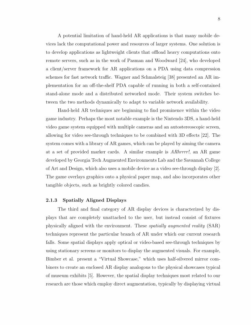
Figure 2.1: Our spatially augmented reality rig is equipped with a singlecamera for object detection and multiple projectors for display. It is designedto fully cover the surface of a centered table, which acts as a space for userinteractions.
with miniature models, as well as in a large-scale, immersive setting with full-scale
walls [33,42].
2.2 3D Registration
In addition to displaying virtual objects within the real world, augmented
reality ideally allows the user to interact with the virtual elements in an intuitive way.
In order to provide convincing visuals and a means for interaction, the virtual objects
and display devices must be registered in 3D relative to the physical environment.
Generally this involves two main steps: calibration and tracking.
2.2.1 Calibration
Calibration refers to the problem of correctly modeling and recovering geo-
metric correspondences between display or tracking devices and the physical envi-
ronment. In the case of projector-based displays, it is necessary that we be able to
map each projector pixel to a known point relative to the world coordinate system
so that we can use that information to project images that are correctly aligned
with the physical display surfaces. In addition, since camera devices are required
12
for vision-based techniques used in the tracking step, these devices must also be
calibrated.
Camera calibration is a classical vision topic that has been researched thor-
oughly. Typically cameras and projectors are described using the pinhole model,
which maps 3D points in the world to 2D image coordinates using both intrinsic
parameters, which describe center, scale, and skewness of the image coordinate sys-
tem, and extrinsic parameters, which describe the rotation and translation of the
camera relative to world coordinates. Zhang [43] provides a simple, robust method
for calibration in which the user captures multiple images of a single, planar calibra-
tion target from differing points of view. The method requires no a priori knowledge
of the position, orientation, or movement of the target relative to the camera. Ad-
ditional research has focused on recovering calibration parameters even in cases
involving significant lens distortion. For example, Scaramuzza et al. [31] provide an
effective means for calibrating omnidirectional cameras, as well as cameras equipped
with a fisheye lens.
2.2.2 Tracking
Once the display and vision devices are properly calibrated within the world
coordinate system, we can use them to accomplish tracking of physical objects for
augmentation. Unlike calibration routines, which typically are done once during
setup, and therefore can accommodate somewhat time-consuming, manual tasks,
tracking must be done automatically and efficiently at interactive rates for the sys-
tem to be responsive. Effective registration has been achieved by utilizing electro-
magnetic and mechanical tracking devices, such as in the CAVE system [8], as well
as vision-based techniques, which are discussed below.
2.2.2.1 Fiducial Markers
A large variety of AR applications use fiducial markers to identify objects
and determine their position and orientation. Kato and Billinghurst [14] provide
a method for tracking square, planar markers with a black border and bi-tonal
interior pattern. Their method identifies markers in the camera image by using edge-
based vision techniques to detect quadrilaterals. Detected regions are normalized,
13
sampled, and compared via correlation to a set of marker patterns provided a priori
by the user. They present their technique in the context of an augmented reality
conferencing system, and have released a working library known as the ARToolkit,
which has since become well-known and widely used within the AR community.
Using a similar quadrilateral-based method, Fiala [10] employs digital processing
techniques to identify square markers bearing ten-digit identification codes, encoded
in the form of six-by-six bitonal grids similar to barcodes. This tracking system,
known as ARTag, provides the user with a large library of predefined markers, and
leverages redundancies in the encoding technique to identify markers even under
conditions of partial occlusion.
Fiducial marker systems hold great promise for AR game applications, as they
provide a viable, inexpensive means of identifying specific game-related objects. For
example, markers could be printed on cards, attached to wooden game pieces, or
positioned at the corners of a movable game board in a manner similar to the aug-
mented whiteboard used in Kato and Billinghurst’s conferencing system [14]. One
disadvantage of fiducial markers is that the robustness and accuracy of the tracking
generally depends on the relative size of the markers in the camera image, since an
image of a marker that is too small or far away may not yield sufficient resolution
for the tracking algorithm to identify the contained pattern. Thus, suitable tracking
may require markers that are too large or unwieldy for players to use comfortably.
In addition, large fiducial markers may interfere with the visual quality of virtual
elements projected onto them. This presents an added problem for projector-based
SAR systems, which, unlike see-through AR displays, cannot fully hide the marker
with rendered objects.
2.2.2.2 Structured Light
Other useful methods for 3D registration employ structured light techniques,
which project known pixel patterns into the scene and measure the result in order
to recover depth information. Ashdown et al. [3] use a variation of structured light
to project successive patterns containing continuous horizontal and vertical lines.
The method detects “kinks” in the lines and uses this information to segment the
14
image into multiple planar regions, which are then stitched together into a contin-
uous display by refining their individual homographies to fit adjacency constraints.
Lee et al. [17] propose a structured light method for registering projection surfaces
without the use of a camera and vision techniques. Instead, the corners of the tar-
get surface are embedded with light sensors, which detect and transmit the binary
sequences projected in the patterns. The system uses this information to identify
the quadrilateral region of the surface within the projector image and warps images
accordingly.
2.2.2.3 Imperceptible Pattern Embedding
A potentially serious hurdle for the application of fiducial marker and struc-
tured light techniques to display systems that use direct augmentation is interference
from projected images. In other words, projecting a colored image onto a surface
bearing a fiducial marker may obscure the pattern of the marker in such a way as to
prevent correct identification by the tracking algorithm. Projected structured light
patterns suffer from the same problem, and may obstruct the displayed images or
otherwise distract the user.
One possible solution to this problem involves directly embedding structured
light patterns into the display images in such a way as to remain imperceptible to
the user. Lee et al. [19] demonstrate an improvement on their previous sensor-based
technique which is able to embed the light patterns into perceptually uniform gray
blocks, which are less distracting than high-contrast patterns. Although the method
is shown to achieve accurate tracking at interactive framerates, regions bearing the
embedded patterns are still visible to the user and reduce the overall display space
available for application content. In addition, the method is shown to work only
with a modified projector that outputs grayscale images.
Cotting et al. [7] propose a method that achieves direct pattern embedding
by taking advantage of unmodified DLP projectors, which use precisely-timed mod-
ulation of micro-mirrors to determine the intensity and color of each image pixel.
Each pixel corresponds to a single mirror, which switches between a “white” po-
sition that tilts toward the projector light source, thus contributing high intensity
15
light to the image, and a “black” position that tilts away, thus contributing little
light. Their method first measures the sequences of mirror flips across the full range
of color values for each independent color channel. Then it remaps each pixel to a
perceptually similar color value such, that during a predetermined exposure time,
the mirror’s position matches the specified black or white value of the desired light
pattern. Using carefully calibrated exposures, the camera can acquire images of
the light pattern without greatly degrading the image quality of the simultaneous
display. Although appealing, short-exposure methods such as this require the extra
work of precisely synchronizing the camera and projectors.
2.2.2.4 Infrared Tracking
Another solution to the problem of simultaneous acquisition and display is to
track objects based only on specific wavelengths of light which are not projected
in significant amounts by the display. A significant amount of research has experi-
mented with tracking using infrared light, which is invisible to the human eye and
therefore does not interfere with displayed images. For example, Lee et al. [18]
have presented the use of a hybrid LED projector capable of transmitting both in-
frared and visible light in order to simultaneously display visible application images
and invisible structured light patterns. Although an excellent proof of concept, the
proposed method does not work with standard commodity projectors.
More recent work has led to the development of commercially available 3D
range cameras, which use infrared structured light techniques to produce real-time
depth images of a measured scene. Perhaps the most widely known example of this
kind of registration is Microsoft’s Kinect, a recent Xbox 360 peripheral that uses a
depth-image camera as an input device for motion-based controls [15,34].
A different approach to infrared-based tracking is to use more conventional
infrared-emitting devices, such as LED markers or laser pens. Kato and Billinghurst
demonstrated the use of an infrared LED-tipped stylus that allowed users to interact
with a virtual whiteboard [14]. The LED activates in response to pressure on the
tip of the stylus, and is detected by a calibrated infrared camera. Because the
surface location of the whiteboard is known, the system is able to determine the
16
location of the pen tip in screen coordinates, allowing the user to write or draw on
the augmented display.
2.2.2.5 Color-based Tracking
Color information provides another potential means for detecting and regis-
tering objects. For example, the Luminous Room project presented by Underkoffler
et al. [37] used a simple tagging system through which application-specific objects
were marked with small groupings of colored dots. The system identifies objects
by first detecting dots as regions of specified size and color, and then by grouping
individual dots based on patterns with known distance and angle constraints. An
advantage of color-based techniques is that they are generally simpler to implement
and at times faster than more sophisticated vision algorithms.
One problem of color-based techniques is that they may not be highly robust
under inconsistent lighting conditions, and are likely to suffer from a high num-
ber of false positives, as target colors may appear within background clutter. The
Luminous Room prototype avoids these problems by using special reflective dot
markers which appear brighter in the camera image, allowing them to be easily
separated from the background. In addition, colored markers share the same prob-
lem as bitonal fiducial markers, in that projected visuals are likely to obscure the
appearance of the marker, making it difficult to achieve simultaneous capture and
display. Despite these drawbacks, color-based object recognition may be useful in
the context of SAR games, since color is commonly used in games to distinguish
objects that appear otherwise identical. Thus it might be possible to track specific
game pieces without the need for added markers.
2.2.2.6 Human Tracking
In addition to tracking physical game pieces, another set of interactions can be
achieved through the tracking of the users. For example, the Kinect tracks the user’s
body and maps it to a skeleton model in real time, allowing for game applications to
use full-body gestural controls [15,34]. Other research has tried to achieve accurate
tracking of specific body parts, most commonly focusing on the human hand. Lee
and Hollerer present Handy AR, a system for markerless tracking that detects and
17
estimates the 3D pose of an out-stretched human hand [20]. This provides the
benefit of allowing the user’s hand to act in place of a fiducial marker, but requires
the hand to remain out-stretched during use. More recently, Wang and Popovic [39]
have proposed using a lightweight colored glove to allow for more robust detection
of a wide variety of hand poses, including such complex gestures as the alphabet
used in American Sign Language.
2.3 Summary
The blending of real and virtual entities through augmented reality has been
the focus of a wide range of research, combining contributions from engineering,
graphics, and computer vision. Augmented reality requires the use of specialized
displays, which have been implemented in various ways, including the use of head-
mounted, hand-held, and spatially aligned devices. In addition, consistently aligning
virtual elements with the physical scene typically requires accurate 3D registration of
physical objects, which has been achieved using electromagnetic devices, structured
light patterns, fiducial markers, and infrared-based or color-based tracking.
3. SAR GAME APPLICATIONS
In this chapter, I will present a number of interesting prototype applications designed
to demonstrate the capabilities of our developing system and to explore possible
uses of SAR techniques. I will describe the basic design of each application and the
user interactions that they facilitate. A more detailed discussion of the underlying
implementation is presented in the next chapter.
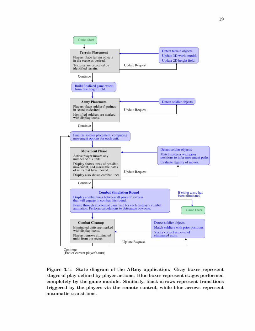
3.1 ARmy Simulation Overview
The ARmy application is a military simulation game played between two op-
ponents. The game is in many ways similar to a typical tabletop war game, in that
it uses miniature objects to create a physical representation of the game world. The
players are given a number of plastic soldier figurines, referred to as units, which
represent their respective armies. Each player moves his units through the scene
according to the rules of the game, engaging in combat with opposing units to elim-
inate them from play. Victory is achieved by completely eliminating the opposing
army.
Most tabletop games are played over a number of turns consisting of multiple
steps, through which the players progress at their own pace. In the same way,
the ARmy application is designed as a series of player-controlled feedback loops,
meaning that the game module only proceeds at the request of the players. The
current implementation relies on a simple wireless remote control, which allows the
players to send two different signals to the game module. The first is an “update
request,” which tells the game to update its model of the scene and display any
new information. The second is a “continue” command, which indicates that the
players have finished with the current stage of play and wish to proceed to the next
step. Figure 3.1 diagrams the overall design of the interaction using a finite state
representation.
In designing this application, special consideration was given as to how SAR
techniques could be leveraged to improve upon the play style of traditional tabletop
18
19
Detect terrain objects.
Update 3D world model.
Update 2D height field.
Build finalized game worldfrom raw height field.
Detect soldier objects.
Detect soldier objects.
Match soldiers with priorpositions to infer movement paths.
Evaluate legality of moves.
Game Start
Army Placement
Players place soldier figurinesin scene as desired.
Identified soldiers are markedwith display icons.
Finalize soldier placement, computingmovement options for each unit.
of units that have moved.
Display also shows combat lines.
Movement Phase
Active player moves anynumber of his units.
Display shows areas of possiblemovement, and marks the paths
Game Over
If either army hasbeen eliminated
Combat Simulation Round
Display combat lines between all pairs of soldiersthat will engage in combat this round.
Iterate through all combat pairs, and for each display a combatanimation. Perform calculations to determine outcome.
Combat Cleanup
Eliminated units are markedwith display icons.
Players remove eliminatedunits from the scene.
Detect soldier objects.
eliminated units.Verify correct removal of
Match soldiers with prior positions.
Update Request
Continue
Update Request
Continue
Continue
Update Request
Terrain Placement
in the scene as desired.
Textures are projected onidentified terrain.
Players place terrain objects
Update Request
Continue(End of current player’s turn)
Figure 3.1: State diagram of the ARmy application. Gray boxes representstages of play defined by player actions. Blue boxes represent stages performedcompletely by the game module. Similarly, black arrows represent transitionstriggered by the players via the remote control, while blue arrows representautomatic transitions.
20
games. This section provides a step-by-step description of how the game is played,
as well as how it incorporates virtual elements to create a new and interesting game
experience.
3.1.1 Terrain Placement
An important aspect of many tabletop games, particularly those that involve
military strategy, is the idea that the game world is not flat and uniform, but
rather that it is characterized by varying terrain. As in the real world, terrain
represents variations in elevation and environment that affect units within the area.
For example, one kind of terrain might represent a swamp that is difficult to walk
through, resulting in a movement penalty to units attempting to move through the
terrain. Another might represent tall grass that provides some degree of cover, thus
making it more difficult to fire at concealed units in combat.
At present, the ARmy prototype provides three simple terrain object types:
high walls, elevated platforms, and ramps. Walls represent tall barriers through
which units cannot move or see. Elevated platforms serve a similar function, but
differ in that units may stand and move around on top of them. Units are not
allowed to “jump” or “climb” from low elevation to high elevation or vice versa,
but must instead use connected ramp objects to walk between the two. Controlling
elevated terrain and ramps is important to the strategy of the game, as units that
hold the higher ground receive a significant advantage in combat.
The game begins with a terrain placement step, during which players decide
on the terrain layout for the table. An appealing aspect of ARmy is that, like
most miniature war games, it allows players to be creative in their construction of
the game world, designing the terrain configuration to suit strategies that seem fun
and exciting. They accomplish this by freely placing provided terrain primitives on
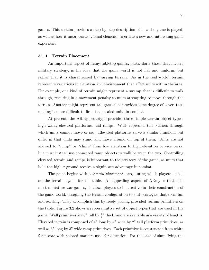
the table. Figure 3.2 shows a representative set of object types that are used in the
game. Wall primitives are 8” tall by 12” thick, and are available in a variety of lengths.
Elevated terrain is composed of 4” long by 4” wide by 2” tall platform primitives, as
well as 5” long by 3” wide ramp primitives. Each primitive is constructed from white
foam-core with colored markers used for detection. For the sake of simplifying the
21
Figure 3.2: ARmy is played using a set of physical props and a simple wire-less remote. The prop library contains plastic soldier figurines and foam-coreterrain objects, including walls, platforms, and ramps
game rules as well as the task of detecting the terrain, it is assumed that platforms
and ramps will not be stacked on top of each other, and that terrain placement
will not change after the game has begun. After both players have agreed upon
an acceptable terrain configuration, they use the remote to signal the application,
which locks their decision.
In traditional miniature war games, players are typically allowed to represent
terrain using whatever objects or methods may be available to them. However,
many players prefer to use objects that physically resemble the terrain that they
represent in order to make it easier for players to remember the meaning of each
object. In addition, realistic terrain objects help to create a more aesthetically
sound environment, which may help some players to feel immersed in the miniature
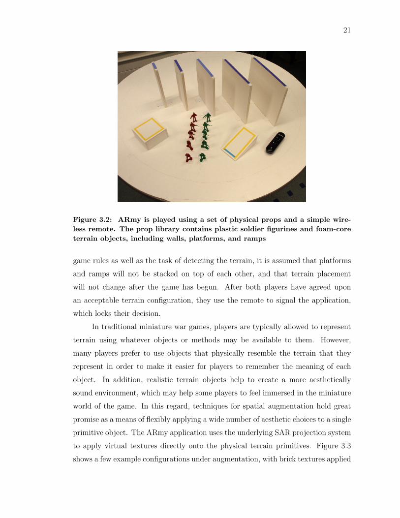
world of the game. In this regard, techniques for spatial augmentation hold great
promise as a means of flexibly applying a wide number of aesthetic choices to a single
primitive object. The ARmy application uses the underlying SAR projection system
to apply virtual textures directly onto the physical terrain primitives. Figure 3.3
shows a few example configurations under augmentation, with brick textures applied
22
Figure 3.3: Players freely arrange terrain objects in the scene, and our systemdetects and augments these objects with virtual textures. Above are three ex-ample configurations, including a simple setup (left), a complex one (middle),and a more complex one with wall objects (right).
to the sides of elevated terrain, and a windowed building facade texture applied to
the wall surfaces. Of course, these textures are merely an example of one possible
aesthetic choice, and could easily be replaced with anything desired by the players,
such as grass, concrete, or sandbags.
It is important to note that many players of miniature war games enjoy con-
structing and customizing terrain objects as much as they enjoy playing the game
itself. For this reason, an ideal application of spatially augmented reality would not
prohibit players from crafting and using such objects. In other words, visual aug-
mentation is not intended to replace fine craftsmanship, but instead to be available
only when players desire it. For example, consider a situation in which a player
wishes to make last-minute changes to a setup, thus requiring him to add primi-
tive objects to an otherwise highly-detailed scene. In this case, projecting a few
well-chosen textures can help maintain the visual integrity of the game.
23
3.1.2 Army Placement
After configuring terrain, players decide on rules for positioning their respective
armies. Units are represented using 2” tall plastic soldier figurines, which have been
colored with red or green spray paint to denote player ownership. As in any figurine-
based tabletop game, units are positioned by physically placing them on the table.
At any point during this step, players may request an update from the game module,
which will then detect all positioned figurines, marking each with a colorful projected
icon to show that it has been recognized, as depicted in Figure 3.5b. When all units
have been placed and recognized satisfactorily, players signal for the game to start.
3.1.3 Movement Phase
Each player’s turn consists of a movement phase, during which he has the
option of moving any number of his units. As in most tabletop war games, a unit’s
movement is constrained to a specified maximum distance, and must conform to the
movement rules dictated by the terrain. However, a crucial difference is that in a
traditional game, players would be required to measure distances using a ruler or
measuring tape, and to make sure that all moves fall within the acceptable range.
As previously stated, one goal of augmenting physical games with elements of video
games is to automate tedious tasks that would otherwise burden the player, as well
as subjective tasks that could lead to disagreements about legality. In this case,
the game module completely eliminates the need for players to manually measure
distances by precisely indicating each unit’s field of movement, and reduces ambi-
guity in rules by notifying players when a move is illegal. Additionally, since players
may move many units at once, the augmentation helps to indicate which units have
already been moved from their initial positions, thereby avoiding a potential source
of confusion.
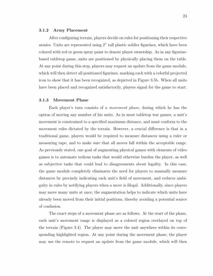
The exact steps of a movement phase are as follows. At the start of the phase,
each unit’s movement range is displayed as a colored region overlayed on top of
the terrain (Figure 3.4). The player may move the unit anywhere within its corre-
sponding highlighted region. At any point during the movement phase, the player
may use the remote to request an update from the game module, which will then
24
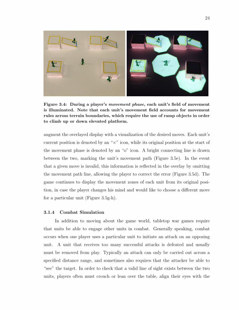
Figure 3.4: During a player’s movement phase, each unit’s field of movementis illuminated. Note that each unit’s movement field accounts for movementrules across terrain boundaries, which require the use of ramp objects in orderto climb up or down elevated platform.
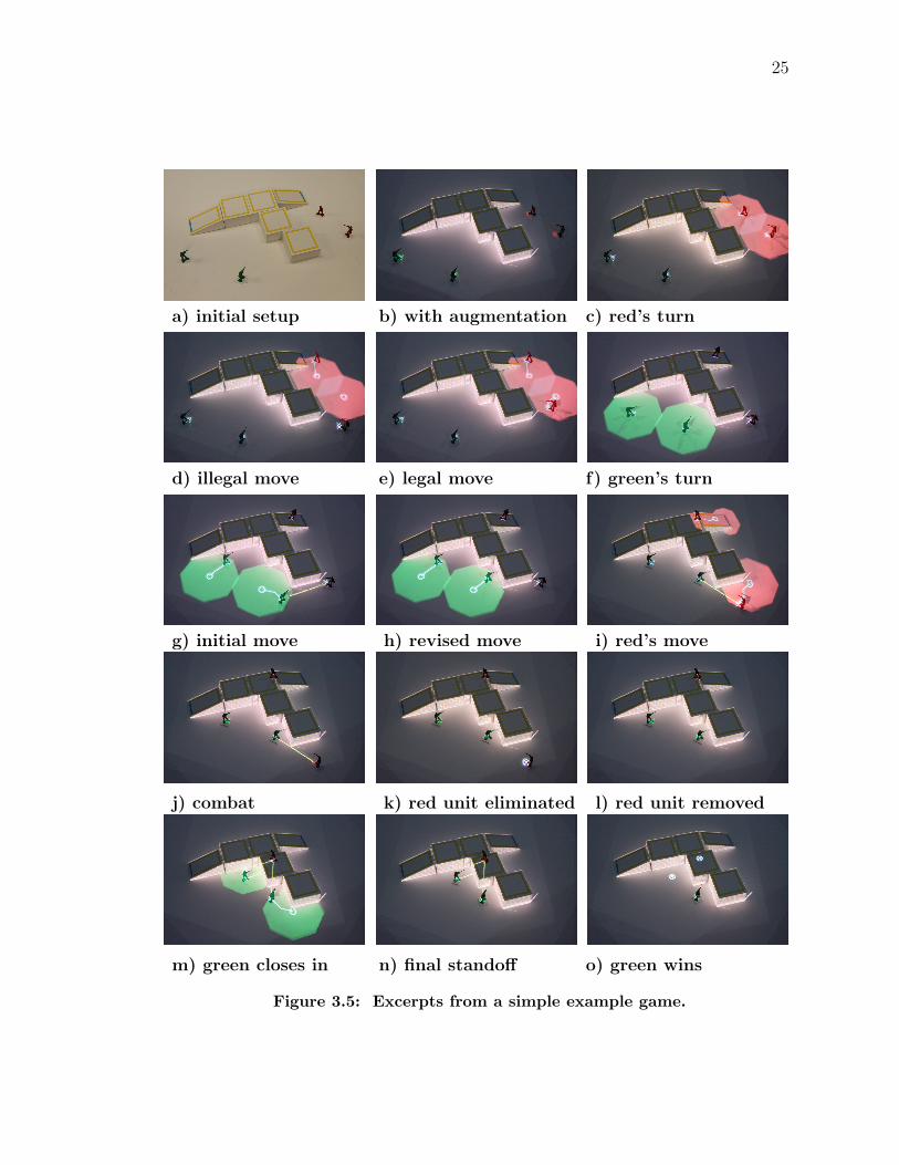
augment the overlayed display with a visualization of the desired moves. Each unit’s
current position is denoted by an “×” icon, while its original position at the start of
the movement phase is denoted by an “o” icon. A bright connecting line is drawn
between the two, marking the unit’s movement path (Figure 3.5e). In the event
that a given move is invalid, this information is reflected in the overlay by omitting
the movement path line, allowing the player to correct the error (Figure 3.5d). The
game continues to display the movement zones of each unit from its original posi-
tion, in case the player changes his mind and would like to choose a different move
for a particular unit (Figure 3.5g-h).
3.1.4 Combat Simulation
In addition to moving about the game world, tabletop war games require
that units be able to engage other units in combat. Generally speaking, combat
occurs when one player uses a particular unit to initiate an attack on an opposing
unit. A unit that receives too many successful attacks is defeated and usually
must be removed from play. Typically an attack can only be carried out across a
specified distance range, and sometimes also requires that the attacker be able to
“see” the target. In order to check that a valid line of sight exists between the two
units, players often must crouch or lean over the table, align their eyes with the
25
a) initial setup b) with augmentation c) red’s turn
d) illegal move e) legal move f) green’s turn
g) initial move h) revised move i) red’s move
j) combat k) red unit eliminated l) red unit removed
m) green closes in n) final standoff o) green wins
Figure 3.5: Excerpts from a simple example game.
26
attacking figurine’s “point of view,” and verify that the target figurine is visible and
unobstructed by terrain or other objects. After a valid attack has been declared,
its effectiveness is determined according to combat rules, which often involve rolling
dice. Once again, all of these tasks represent prime opportunities for automation.
The current game prototype handles combat in a different manner from typical
miniature war games, in that attacks are not explicitly declared by the players.
Instead, each movement phase is followed by a combat simulation round, during
which all units automatically attack available targets in range. This is somewhat
more similar to how combat works in a typical real-time strategy (RTS) video game,
in which individual units exhibit a certain amount of autonomy in their actions,
following orders only to the extent allowable by their preprogrammed behaviors.
The idea of commanding “smart” units in combat interactions is not something that
can be practically simulated by traditional tabletop war games, but is an interesting
possibility for augmented reality games like ARmy.
As players move units around the battlefield, yellow “combat lines” are over-
layed on the ground textures, connecting opposing units that are able to attack each
other (Figure 3.5j). This visualization provides important feedback to help players
plan moves strategically. During a subsequent combat round, the game module
iterates through all such connected pairs and in each case simulates an individual
contest, which results in either one unit winning by successfully eliminating the
other, or in a tie, in which case neither is eliminated. The contest consists of a
simple “dice roll” calculation, which assigns each unit a probability value represent-
ing the likeliness of winning, weighted according to strategic advantages, such as
holding higher ground than the opponent. At the end of the combat simulation
round, units that have been eliminated are marked with a white “⊗” icon, signaling
to the players that these figurines should be removed from play (Figure 3.5k). Once
all eliminated units have been correctly removed, the players signal for the game to
continue into the next movement phase.
27
3.2 Large-scale Applications
In addition to the small-scale tabletop AR system, our research group has de-
veloped a large-scale equivalent that aims to provide users with an immersive display
environment [42]. The differences between the two systems will be discussed later
in the implementation details, but it should be mentioned that a key aspect of the
large-scale system is its ability to continuously acquire updated views of the scene ge-
ometry while simultaneously displaying the AR visualization. In other words, while
applications developed on the tabletop are typically updated only by user-driven
commands, such as in the turn-based game detailed above, our large-scale applica-
tions are able to run continuously, responding to user actions at interactive rates.
The applications discussed in this section were developed to explore and demon-
strate the kinds of novel, tangible interactions that would be possible if everyday
objects were augmented through similar SAR techniques.
3.2.1 Ping Pong
A prominent feature of our large-scale display environment is the use of full-
size projection surfaces, which users may freely move in order to interact with the
application and control the space. Many of the applications supported by our system
utilize these surfaces as a means of user input to the system. For example, the
original target application for our system is a lighting simulation for architectural
design, which allows users to experiment with interior designs by using the projection
surfaces as direct analogues to the physical walls of a room [33].
In line with this idea, we wanted to explore the possibility of using these sur-
faces as unorthodox game controllers. In developing such applications, we felt it
absolutely critical that the function of the surfaces seem natural within the appli-
cation setting, such that users may interact with the game intuitively and without
detailed instruction. With this goal in mind, we developed a virtual ping pong game
as a prototype application (Figure 3.6). The design was inspired by the iconic video
game Pong [1], and strives to reimagine its classic interactions in the context of
augmented reality.
As in traditional, real-life ping pong, the game is played between two opposing
28
Figure 3.6: A game of immersive augmented reality ping pong.
sides, each of which strives to bounce the ball past the opponent’s paddle in order
to score points. In this case, instead of using a table, the court is a large area of the
floor, marked with a white rectangular boundary and a single dividing line drawn
down the center. Like the court lines, the ball is a virtual element projected onto
the floor. Each side is given a single movable projection surface, which acts as a
paddle. When the ball intersects the bottom of a paddle surface, it is deflected off in
a direction consistent with the surface angle. Because it is easier for a pair of users
to manipulate a surface when working together than it is for a single user, the game
is typically played with teams of two. Each paddle surface is augmented to display
its corresponding team’s color, and additional projection surfaces located outside of
the play area are used to display each side’s current score.
3.2.2 Laser Pen Applications
Although a wide variety of applications are possible using the physical interac-
tions of the projection surfaces alone, we felt that in many cases users would benefit
from the ability to interact with virtual elements in the scene using a more precise
means. Recent work on our system has introduced the use of laser pens to allow
users to point directly at displayed objects for a variety of interactions. The devices
used are commonplace green laser pens, typically used for pointing during presen-
tations. Overall, we find that the laser pen interface provides an excellent way for
users to perform tasks both independently and cooperatively across the wide display
29
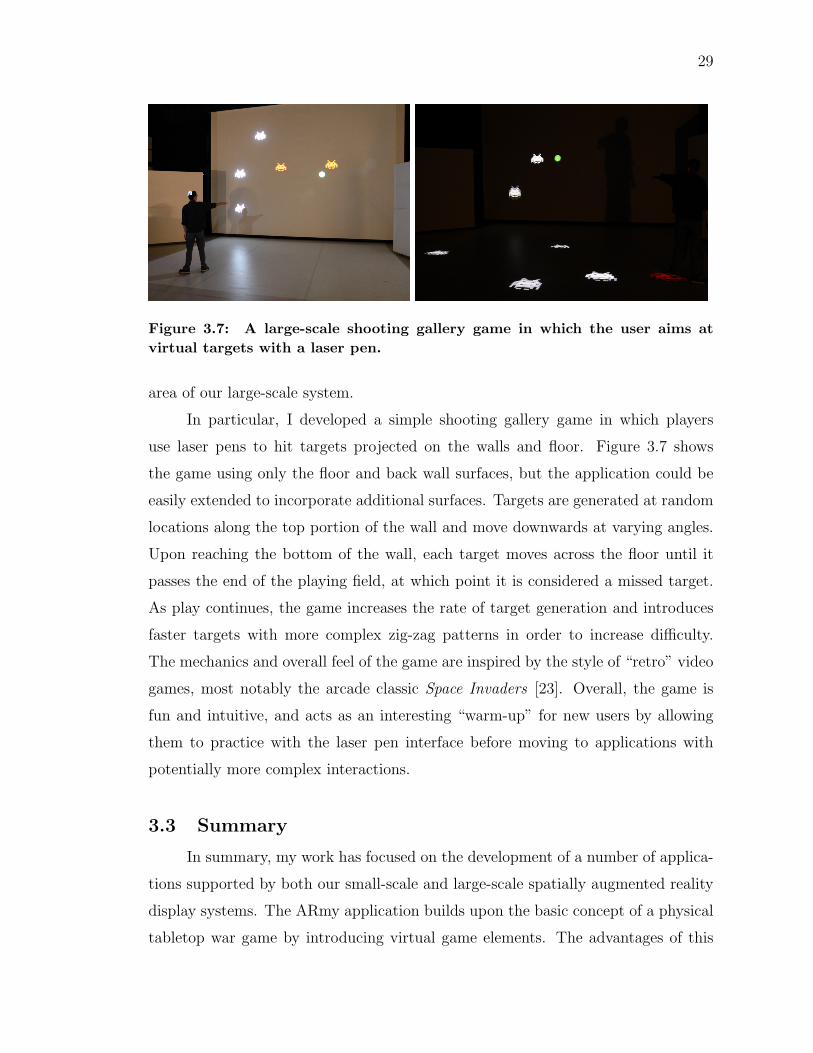
Figure 3.7: A large-scale shooting gallery game in which the user aims atvirtual targets with a laser pen.
area of our large-scale system.
In particular, I developed a simple shooting gallery game in which players
use laser pens to hit targets projected on the walls and floor. Figure 3.7 shows
the game using only the floor and back wall surfaces, but the application could be
easily extended to incorporate additional surfaces. Targets are generated at random
locations along the top portion of the wall and move downwards at varying angles.
Upon reaching the bottom of the wall, each target moves across the floor until it
passes the end of the playing field, at which point it is considered a missed target.
As play continues, the game increases the rate of target generation and introduces
faster targets with more complex zig-zag patterns in order to increase difficulty.
The mechanics and overall feel of the game are inspired by the style of “retro” video
games, most notably the arcade classic Space Invaders [23]. Overall, the game is
fun and intuitive, and acts as an interesting “warm-up” for new users by allowing
them to practice with the laser pen interface before moving to applications with
potentially more complex interactions.
3.3 Summary
In summary, my work has focused on the development of a number of applica-
tions supported by both our small-scale and large-scale spatially augmented reality
display systems. The ARmy application builds upon the basic concept of a physical
tabletop war game by introducing virtual game elements. The advantages of this

30
method are that it provides an intuitive interface and display, allowing players to
easily see available options, and that it automates a number of tedious tasks that
might ordinarily encumber play, such as measuring distances, checking lines of sight,
and performing arithmetic for calculations in combat. The large-scale applications
explore possible ways in which users may interact with our system, by directly mov-
ing physical projection surfaces to alter the scene, and by using laser pointers to
precisely interact with virtual elements.
4. IMPLEMENTATION DETAILS
1
The spatially augmented reality game applications presented in the previous
chapter are built on top of a system for dynamic projection developed through
ongoing work by members of our computer graphics research group. The purpose
of this chapter is not to explain the details of our system in depth, but rather to
provide a general overview of how the system is organized, and to explain how each
of the existing components is used to create the game applications. I will highlight
the algorithms that I personally contributed to the system infrastructure and I will
also explain how I prototyped the game applications by adapting and extending
portions of the system developed by other students.
4.1 System Overview
Although our small-scale and large-scale systems differ in a number of ways,
the two can be understood as variations of a single design, divided into a number
of components. The purpose of this section is to provide a high-level outline of this
system, describing the role of each individual component.
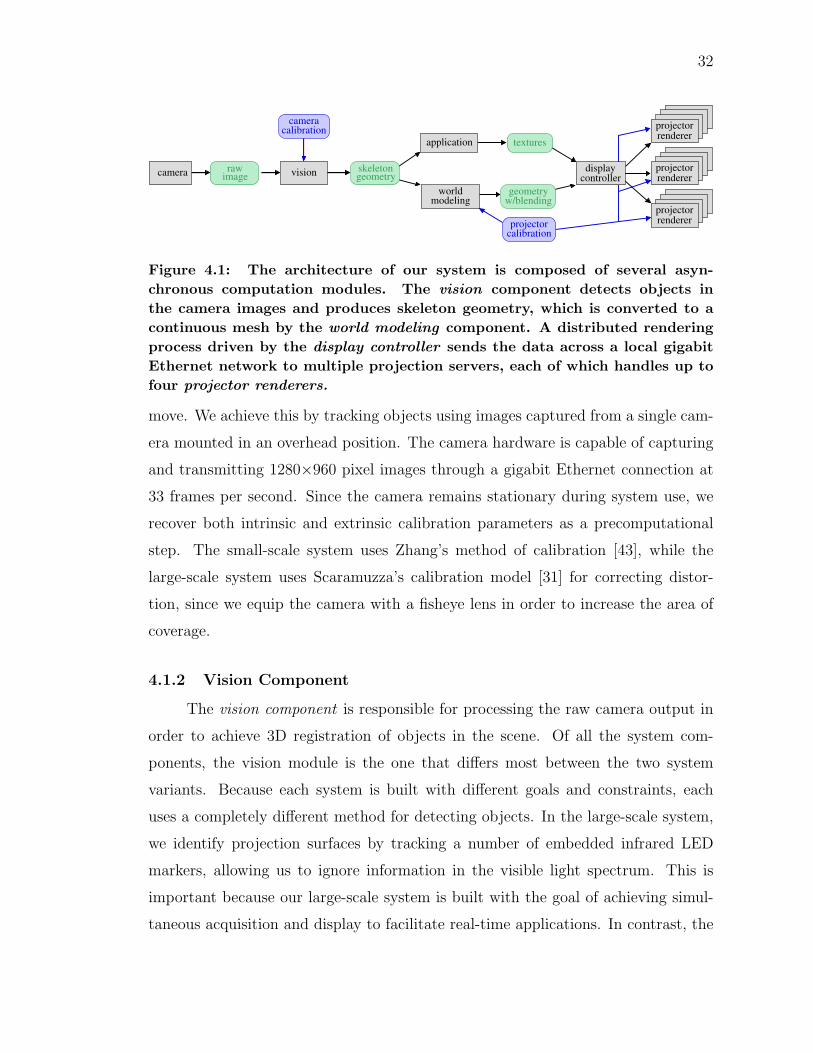
An important principle of the general system design is that each component
represents a single autonomous process. Since the various responsibilities of a given
component may require it to run at different rates than others, we decouple them
such that at any point in time, a process can obtain the latest output from the
previous stage of the pipeline (Figure 4.1).
4.1.1 Camera Component for Scene Recognition and Tracking
Projecting images onto a dynamic scene requires that our system be able to
accurately recover the positions and orientations of objects and surfaces as they
1Portions of this chapter previously appeared as: Theodore C. Yapo, Yu Sheng, Joshua Nasman,Andrew Dolce, Eric Li, and Barbara Cutler. Dynamic Projection Surfaces for Immersive Visu-alization. PROCAMS 2010 IEEE International Workshop on Projector-Camera Systems, June2010.
31
32
calibrationprojector
calibrationcamera
geometryskeleton
w/blendinggeometry
textures
rawimage
application
controllerdisplay projector
renderer
projectorrenderer
projectorrenderer
world
camera vision
modeling
Figure 4.1: The architecture of our system is composed of several asyn-chronous computation modules. The vision component detects objects inthe camera images and produces skeleton geometry, which is converted to acontinuous mesh by the world modeling component. A distributed renderingprocess driven by the display controller sends the data across a local gigabitEthernet network to multiple projection servers, each of which handles up tofour projector renderers.
move. We achieve this by tracking objects using images captured from a single cam-
era mounted in an overhead position. The camera hardware is capable of capturing
and transmitting 1280×960 pixel images through a gigabit Ethernet connection at
33 frames per second. Since the camera remains stationary during system use, we
recover both intrinsic and extrinsic calibration parameters as a precomputational
step. The small-scale system uses Zhang’s method of calibration [43], while the
large-scale system uses Scaramuzza’s calibration model [31] for correcting distor-
tion, since we equip the camera with a fisheye lens in order to increase the area of
coverage.
4.1.2 Vision Component
The vision component is responsible for processing the raw camera output in
order to achieve 3D registration of objects in the scene. Of all the system com-
ponents, the vision module is the one that differs most between the two system
variants. Because each system is built with different goals and constraints, each
uses a completely different method for detecting objects. In the large-scale system,
we identify projection surfaces by tracking a number of embedded infrared LED
markers, allowing us to ignore information in the visible light spectrum. This is
important because our large-scale system is built with the goal of achieving simul-
taneous acquisition and display to facilitate real-time applications. In contrast, the
33
small-scale system does not provide this feature, and instead detects objects using
simple colored markers, making the objects lighter, cheaper, and easier to construct.
In either case, the output of the vision module is a list of detected objects and as-
sociated positional data, which we refer to as the “skeleton geometry” of the scene.
4.1.3 World Modeling Component
Skeleton geometry alone generally does not provide a sufficient representation
of the scene for augmentation. Instead, this information is passed to the world mod-
eling component, which is responsible for constructing a more complete environment
model in order to suit the needs of the rendering modules, and sometimes the ap-
plication. The output is a three-dimensional virtual model of the scene in the form
of a triangle mesh. Additionally, two-dimensional heightfield representations of the
scene can be provided if needed by a particular application.
4.1.4 Display Controller and Projector Renderers
Because the number of projectors that a particular machine may drive is lim-
ited to the number DVI output ports that it provides, our system uses a distributive
rendering process to divide the workload across multiple computers. Our most re-
cent configuration is capable of driving a maximum of eight projectors by using two
servers, each equipped with two dual-head graphics cards. We accomplish this using
a single display controller, which coordinates a number of remote projector renderer
modules. The display controller sends relevant display information to the separate
renderers, including the geometric model and textures. Each projector renderer
controls the display of a single projector and generates the final display image by
rendering the virtual model of the scene from the perspective of the projector based
on calibration data.
4.2 ARmy Application Details
The ARmy application was built on top of the small-scale version of our sys-
tem. This section explains in greater detail the ways in which the application inter-
acts with the underlying system modules, as well as the algorithms used to perform
34
various game operations.
4.2.1 Object Detection
During acquisition, a single image from the camera is processed by our vision
module, which uses thresholding techniques to identify connected image components
with predominant color attributes matching a set of identifiable colors. Currently
the set is limited to six colors : red, green, blue, yellow, cyan, and magenta. This
six-color vocabulary has proven sufficient for a number of applications developed
using the system.
After a colored component is detected, the vision module attempts to classify
it as a known object type based on a set of rules dictated by the current application.
In the case of the ARmy application, the vision module is equipped with a set of
rules specifically tuned for detecting the game object primitives. Because the game
is designed with the assumption that terrain does not change beyond the initial
setup phase, which occurs before soldier units have been placed in the scene, the
classification rules can be separated into two distinct sets, allowing the vision module
to operate in separate modes.
The first mode is used only in the terrain placement phase of the game to detect
the initial configuration of terrain objects, which are encoded with the colors blue,
yellow, and cyan. Blue components that fit a rectangular shape within an acceptable
margin of error are classified as wall objects. Platform objects are detected in the
image as yellow components with a valid quadrilateral fit. Similarly, ramps are
classified from quadrilateral components with three predominantly yellow sides and
one predominantly cyan side. The cyan side indicates the low edge of the ramp,
which reaches down to the table surface. Once an appropriate quadrilateral has
been fit to a terrain object, the corners are used to specify position and orientation.
After the terrain setup has been finalized, subsequent scene recognition steps
use the second detection mode, which is responsible for identifying soldiers. Since
red and green colors are reserved for soldier figurines, any red or green component
that falls within an acceptable range of sizes can be classified as a soldier unit. Each
detected unit is assigned a single location equal to the centroid of the component in
35
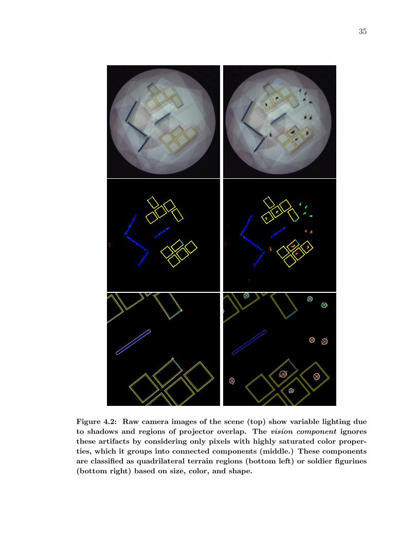
Figure 4.2: Raw camera images of the scene (top) show variable lighting dueto shadows and regions of projector overlap. The vision component ignoresthese artifacts by considering only pixels with highly saturated color proper-ties, which it groups into connected components (middle.) These componentsare classified as quadrilateral terrain regions (bottom left) or soldier figurines(bottom right) based on size, color, and shape.
36
image space.
In either case, any detected component that does not fit a specified classifica-
tion rule is deemed irrelevant and discarded. Once a component has been classified
as a valid object, its known world dimensions are used in combination with the
calibration data of the camera to determine its position and orientation in world
space. For any given pixel coordinates in the camera image, the calibration param-
eters define a ray in 3D space representing the corresponding path along which light
enters the camera. By using the known height of the object at that point, we can
backproject along the ray to determine the exact world position.
Overall, our color-based detection method successfully recognizes a variety of
objects without the need for large fiducial markers or embedded sensors, allowing us
to easily construct a sizeable collection of lightweight objects. Objects with natural
color properties, such as brightly colored game pieces, can often be tracked without
any modification, while objects that lack these properties can be tracked with the
simple addition of colored markers.
4.2.2 Modeling the Game World
The game world is represented as a two-dimensional heightfield, discretized
into a high-resolution square grid. The purpose of this grid is to allow the game
module to approximate the travel distances of units as they move through the scene,
as well as to perform line-of-sight checks for combat purposes. In addition to a
height value, each cell stores the cost of moving from the cell to each of its eight
neighbors, subject to a maximum height difference threshold. If the difference in
height of two adjacent cells is below the threshold, then the cells are considered
connected neighbors, and the associated movement cost is equal to the Euclidean
distance between the two, which is simply 1 for neighbors along cardinal directions
and√
2 for diagonal neighbors. If the height difference is above the threshold, then
it is impossible for a unit to move between the two, and therefore the distances are
set to infinity. Because the terrain configuration does not change after the terrain
placement step, these distance values are computed once for all cells and stored for
the remainder of the game. Since each cell is connected to at most eight neighbors,
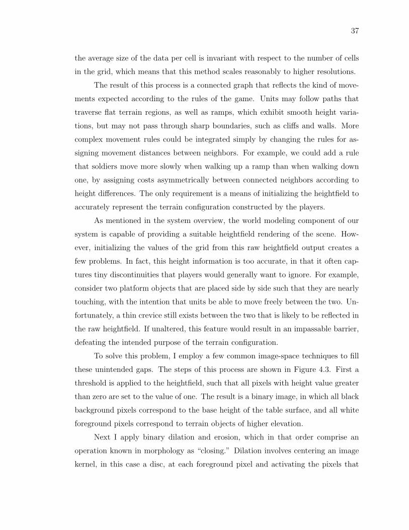
37
the average size of the data per cell is invariant with respect to the number of cells
in the grid, which means that this method scales reasonably to higher resolutions.
The result of this process is a connected graph that reflects the kind of move-
ments expected according to the rules of the game. Units may follow paths that
traverse flat terrain regions, as well as ramps, which exhibit smooth height varia-
tions, but may not pass through sharp boundaries, such as cliffs and walls. More
complex movement rules could be integrated simply by changing the rules for as-
signing movement distances between neighbors. For example, we could add a rule
that soldiers move more slowly when walking up a ramp than when walking down
one, by assigning costs asymmetrically between connected neighbors according to
height differences. The only requirement is a means of initializing the heightfield to
accurately represent the terrain configuration constructed by the players.
As mentioned in the system overview, the world modeling component of our
system is capable of providing a suitable heightfield rendering of the scene. How-
ever, initializing the values of the grid from this raw heightfield output creates a
few problems. In fact, this height information is too accurate, in that it often cap-
tures tiny discontinuities that players would generally want to ignore. For example,
consider two platform objects that are placed side by side such that they are nearly
touching, with the intention that units be able to move freely between the two. Un-
fortunately, a thin crevice still exists between the two that is likely to be reflected in
the raw heightfield. If unaltered, this feature would result in an impassable barrier,
defeating the intended purpose of the terrain configuration.
To solve this problem, I employ a few common image-space techniques to fill
these unintended gaps. The steps of this process are shown in Figure 4.3. First a
threshold is applied to the heightfield, such that all pixels with height value greater
than zero are set to the value of one. The result is a binary image, in which all black
background pixels correspond to the base height of the table surface, and all white
foreground pixels correspond to terrain objects of higher elevation.
Next I apply binary dilation and erosion, which in that order comprise an
operation known in morphology as “closing.” Dilation involves centering an image
kernel, in this case a disc, at each foreground pixel and activating the pixels that
38
a) b) c)
d) e)
Figure 4.3: The game world is constructed by beginning with an initial height-field rendering of the scene (a) and filling in unwanted discontinuities. First athreshold is applied (b) to separate the floor from elevated terrain. The nextimages show the results after dilation (c), and erosion (d), with green regionsindicating differences from the original heightfield. These pixels are assignednew height values (e) to form the final, corrected heightfield.
are overlapped. This expands the foreground regions, filling in tight crevices and
other undesired features. Erosion performs another sweep with the same kernel,
but instead deactivates locations where the kernel overlaps any background pixels.
This reduces the foreground components back to their approximate original size,
but leaves the newly filled features intact.
Finally, the modified image is compared to the original threshold image. For
each newly activated pixel, I assign a new reasonable height value equal to that of the
nearest nonzero pixel in the raw heightfield. Although the method may sometimes
lose minor details, such as sharp internal corners, the end result is a heightfield that
more closely matches expected continuities.
39
4.2.3 Tracking Soldier Movement
When a unit is placed at a given location in the scene, the game module must
determine all possible movement options. It does this by performing a breadth-
first search across the connected graph, through which it enumerates all possible
destination points, as well as an estimate of the minimum distance required to
reach each destination. The search is limited by the unit’s maximum movement
distance, such that only positions reachable by legal movement paths are generated.
The path enumeration algorithm results in movement using grid-based dis-
tances instead of straight-line Euclidean distances. Because each path consists only
of transitions between neighboring grid cells, units are effectively restricted to move-
ment along the primary eight directions. To illustrate this, consider a unit standing
in a region of completely flat terrain with no obstructions, such as the unit at the
center of the configuration shown in Figure 3.4. In a typical miniature war game,
the unit can move to any point within a surrounding circle of radius equal to the
maximum movement distance. However, according to the movement rules of the
current ARmy implementation, the unit’s movement is constrained to an octagon,
since it may only travel to locations reachable by a combination of cardinal and
diagonal moves. Although this could be corrected by a more complex pathing al-
gorithm, preliminary player feedback has suggested that the octagonal regions are
acceptable and do not greatly detract from play.
With the limited resolution of the camera and the general challenges of com-
puter vision, it is impossible to uniquely distinguish the nearly identical soldiers as
they are moved across the table. Our current technique is limited by an inability to
distinguish between objects of similar size, color, and shape, as well as infrequent
picture updates due to the requirement that users move out of the scene during
acquisition. As a result, the game module must maintain identification of each unit
on a frame-to-frame basis by relying on temporal coherence alone.
One way to easily fix this problem would be to divide the movement phase into
a number of smaller phases, each of which would restrict the player to moving a single
specified unit. However, this would result in slower, more tedious play, requiring
the players to pause for updates many times per turn. Instead, the player is allowed

40
to simultaneously move any number of his units, requesting a new acquisition only
when he would like to see an updated display or has decided on a final configuration.
The simultaneous movement of multiple units means that at each update, the
game module must have some way of mapping the last known configuration of units
to the the newly acquired one, and of verifying that the changes constitute a set
of legal moves. This is achieved using the Kuhn-Munkres algorithm, sometimes
known as the Hungarian method [16, 21]. The current application uses an existing
open-source implementation, written by John Weaver and made available for free
use under the GNU General Public License [40].
Consider a set of m 2D locations representing the configuration of a player’s
units before an update, and a set of n locations representing the newly detected posi-
tions of the units after the update. The input to the matching algorithm is an m×nmatrix A, such that each coefficient Aij is equal to the assignment cost of matching
the ith unit of the old configuration to the jth unit of the new configuration. In this
case, the assignment cost is simply set to the minimum valid movement distance
between the two positions, as computed by the breadth-first search of the previous
path enumeration step. If no valid move exists between the two points, either due
to impassable terrain or maximum distance constraints, then the assignment cost is
set to a large value representing infinity.
The result of the matching algorithm is a mapping that allows the game module
to reasonably maintain correct identification of each unit across movement frames.
Because the algorithm does not require that the two sets be of the same cardinality,
this method robustly handles error cases in which units might have been illegally
added or removed from the scene, by correctly identifying extraneous or missing
units.
Nevertheless, it should be noted that the resultant mapping is not always ex-
actly what players might expect. For example, consider a situation in which two
units cross paths, such that each ends in a location relatively close to the other’s
starting location. In this situation it is quite likely that the game module will
incorrectly swap the identities of the two units. Although this artifact is clearly
undesirable and may cause potential confusion, it does not actually have any conse-
41
quences on the state of the game, since the current prototype assumes that all units
are functionally equivalent. However, a more complex set of game rules involving
multiple types of units with individual state information would obviously require a
more robust means of identification and tracking.
4.2.4 Line of Sight Calculation
As explained in the combat simulation section of the game overview (3.1.4),
units may only attack targets that fall within a maximum firing distance, and that
are visible through an unobstructed line of sight. Because of the two-dimensional
heightfield representation of the game world, performing automatic visibility tests
is a relatively trivial matter. Given two viewpoints of specified location and height,
the game module simply fits a three-dimensional line between the two, and then
discretizes the line into segments based on an interval with length smaller than the
width of a single grid cell. At each of these sampled points, the method verifies that
the height of the terrain field is less than that of the line. If no point violates this
property, then the line of sight is deemed valid.
4.2.5 Visual Augmentation
The ability to apply virtual textures to specific physical objects and surfaces in
the scene is a basic primary feature of our dynamic projection system. As described
above, the positions and orientations of detected objects are used by our world
modeling component to create a virtual representation of the scene in the form of
a three-dimensional mesh. This module is also responsible for assigning material
identifiers, as well as texture coordinates, to each distinct surface, which are then
used by applications and other system modules to specify textures for display. In
other words, applications use the projection system to augment objects by assigning
textures to each of the identified surfaces (Figure 4.4).
This allows the game to easily display information to the players by main-
taining a single overlay texture, which is shared by the table surface and the top
surfaces of all platforms and ramps. The overlay is of the same resolution as the
512×512 heightfield, such that each pixel corresponds directly to a single position in
the game world. Although this resolution is sufficient for covering the 42’ diameter
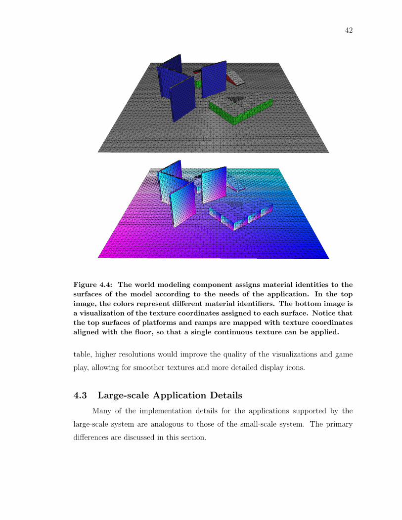
42
Figure 4.4: The world modeling component assigns material identities to thesurfaces of the model according to the needs of the application. In the topimage, the colors represent different material identifiers. The bottom image isa visualization of the texture coordinates assigned to each surface. Notice thatthe top surfaces of platforms and ramps are mapped with texture coordinatesaligned with the floor, so that a single continuous texture can be applied.
table, higher resolutions would improve the quality of the visualizations and game
play, allowing for smoother textures and more detailed display icons.
4.3 Large-scale Application Details
Many of the implementation details for the applications supported by the
large-scale system are analogous to those of the small-scale system. The primary
differences are discussed in this section.
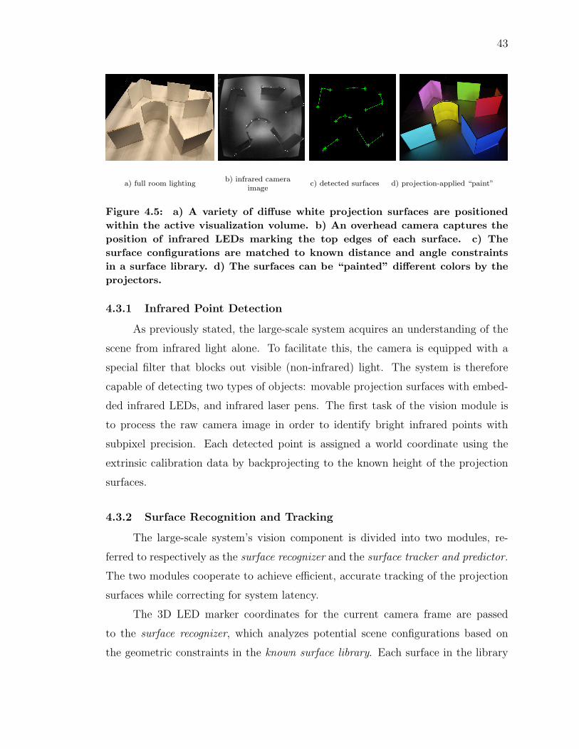
43
a) full room lightingb) infrared camera
imagec) detected surfaces d) projection-applied “paint”
Figure 4.5: a) A variety of diffuse white projection surfaces are positionedwithin the active visualization volume. b) An overhead camera captures theposition of infrared LEDs marking the top edges of each surface. c) Thesurface configurations are matched to known distance and angle constraintsin a surface library. d) The surfaces can be “painted” different colors by theprojectors.
4.3.1 Infrared Point Detection
As previously stated, the large-scale system acquires an understanding of the
scene from infrared light alone. To facilitate this, the camera is equipped with a
special filter that blocks out visible (non-infrared) light. The system is therefore
capable of detecting two types of objects: movable projection surfaces with embed-
ded infrared LEDs, and infrared laser pens. The first task of the vision module is
to process the raw camera image in order to identify bright infrared points with
subpixel precision. Each detected point is assigned a world coordinate using the
extrinsic calibration data by backprojecting to the known height of the projection
surfaces.
4.3.2 Surface Recognition and Tracking
The large-scale system’s vision component is divided into two modules, re-
ferred to respectively as the surface recognizer and the surface tracker and predictor.
The two modules cooperate to achieve efficient, accurate tracking of the projection
surfaces while correcting for system latency.
The 3D LED marker coordinates for the current camera frame are passed
to the surface recognizer, which analyzes potential scene configurations based on
the geometric constraints in the known surface library. Each surface in the library
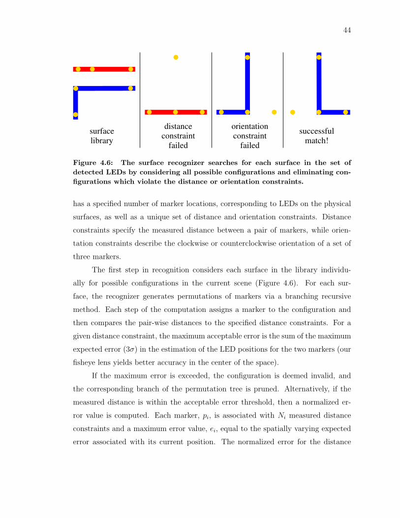
44
constraintsurfacelibrary
distance
failed failed
successfulmatch!
constraintorientation
Figure 4.6: The surface recognizer searches for each surface in the set ofdetected LEDs by considering all possible configurations and eliminating con-figurations which violate the distance or orientation constraints.
has a specified number of marker locations, corresponding to LEDs on the physical
surfaces, as well as a unique set of distance and orientation constraints. Distance
constraints specify the measured distance between a pair of markers, while orien-
tation constraints describe the clockwise or counterclockwise orientation of a set of
three markers.
The first step in recognition considers each surface in the library individu-
ally for possible configurations in the current scene (Figure 4.6). For each sur-
face, the recognizer generates permutations of markers via a branching recursive
method. Each step of the computation assigns a marker to the configuration and
then compares the pair-wise distances to the specified distance constraints. For a
given distance constraint, the maximum acceptable error is the sum of the maximum
expected error (3σ) in the estimation of the LED positions for the two markers (our
fisheye lens yields better accuracy in the center of the space).
If the maximum error is exceeded, the configuration is deemed invalid, and
the corresponding branch of the permutation tree is pruned. Alternatively, if the
measured distance is within the acceptable error threshold, then a normalized er-
ror value is computed. Each marker, pi, is associated with Ni measured distance
constraints and a maximum error value, ei, equal to the spatially varying expected
error associated with its current position. The normalized error for the distance
45
constraint between markers pi and pj is computed as follows:
Eij =
(ei
Ni
+ej
Nj
)(|d− d0|ei + ej
), (4.1)
where d is the distance between the detected positions of pi and pj, and d0 is the
ideal distance specified by the constraint.
This normalization ensures that the total error for an acceptable configuration
will not exceed the sum of the maximum expected errors of its markers, a property
that is important during the next step of recognition. Each complete permutation
that does not violate distance constraints is then checked for agreement with the
known orientation constraints, and each valid configuration is assigned an error
equal to the sum of the normalized error values of all its distance constraints.
In the second step, the recognizer combines the possible individual surface
configurations into a single scene configuration (Figure 4.5c). The optimal solution
is found by performing a best-first tree search (Figure 4.7). The search begins with
an empty node containing no assignments. At each step, the node with minimum
total cost is expanded by selecting a surface and generating a new node for each
of the possible configurations of that surface. We also allow that no configuration
is chosen for the surface, as it may not currently be within the field of view of the
camera. Configurations that re-use the same LED are eliminated.
The total cost of a given node is equal to the sum of the configuration error
values for each surface that has been assigned, plus additional error for each detected
LED that is not used in any surface assignment. The error for each unassigned
marker is equal to the maximum calibration error at that spatial location, and
is therefore the same value used for thresholding the distance constraints in the
first step of recognition. Equation (4.1) ensures that the total cost for assigning a
configuration is always less than the cost of excluding it, which means that a given
configuration will always be included in the solution unless it conflicts with a better
configuration. The result is a relatively robust algorithm that excludes incorrect
matches while still favoring results that incorporate as many surfaces as possible.
In cases where extraneous markers are detected, it is possible for incorrect
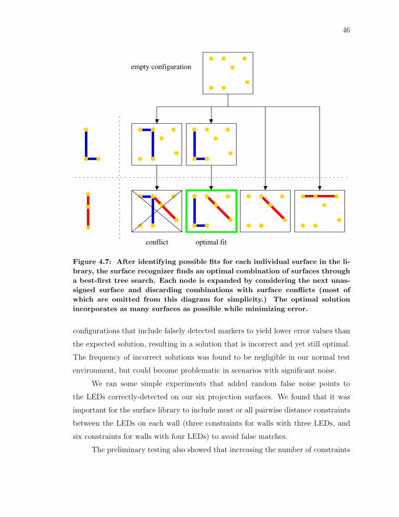
46
optimal fit
empty configuration
conflict
Figure 4.7: After identifying possible fits for each individual surface in the li-brary, the surface recognizer finds an optimal combination of surfaces througha best-first tree search. Each node is expanded by considering the next unas-signed surface and discarding combinations with surface conflicts (most ofwhich are omitted from this diagram for simplicity.) The optimal solutionincorporates as many surfaces as possible while minimizing error.
configurations that include falsely detected markers to yield lower error values than
the expected solution, resulting in a solution that is incorrect and yet still optimal.
The frequency of incorrect solutions was found to be negligible in our normal test
environment, but could become problematic in scenarios with significant noise.
We ran some simple experiments that added random false noise points to
the LEDs correctly-detected on our six projection surfaces. We found that it was
important for the surface library to include most or all pairwise distance constraints
between the LEDs on each wall (three constraints for walls with three LEDs, and
six constraints for walls with four LEDs) to avoid false matches.
The preliminary testing also showed that increasing the number of constraints
47
results in the early rejection of many incorrect configurations and in some cases
improves the running time. In tests involving 22 real points and 60 noise points, we
found that adding constraints improves the results but does not reduce the frequency
of error to an acceptable level for most applications. Therefore, systems operating
in noisier environments may require a different approach. The current recognition
algorithm can process up to 90 markers at an acceptable real-time frame rate, but
is not scalable for significantly larger numbers.
The surface tracker and predictor module compensates for system latency by
predicting future surface locations based on movement from frame to frame. Al-
though it is possible to simply use the results of the surface recognizer for projec-
tion, the latency between the tracking and display of the current frame results in
projections that appear to lag behind their target moving surfaces. We mitigate
this issue by using an intermediate predictive tracking module to achieve greater
stability and to correct for latency in our asynchronous system components. This
module tracks each marker from frame to frame by maintaining a Kalman filter [13]
to increase the accuracy of the predictions.
The tracking module checks for new output from the surface recognizer, and
uses the detected locations as measurements for updating the corresponding Kalman
filters and generating the posterior state estimations, including locations and veloc-
ities. The predicted surface location is the sum of posterior location estimation
from the Kalman filter and a displacement computed by multiplying the Kalman-
corrected velocity and a timestep tuned to match the latency of the current appli-
cation.
Our current surface library with six moving projection surfaces contains a total
of 22 markers. During typical use of the system, we occasionally receive one or two
falsely detected markers as a result of noise from extraneous infrared sources. The
LED detection process and surface recognizer each run at 33 frames per second,
which is the maximum transfer speed of the camera. The surface recognizer is
capable of running at much higher framerates on the tested surface library, but is
constrained to run only on new data from the camera module. The surface tracker
and predictor is likewise constrained to update the Kalman filter at the camera
48
framerate, but benchmarking suggests it could be used at much greater speeds with
a correspondingly faster camera.
4.3.3 Laser Pen Detection
If the application module is compatible with laser pen input, then detected
points that do not fit valid surface configurations are assumed to be reflected light
at the target location of a laser pen. In this case, the pixel coordinate is compared
to a number of image masks representing the visible regions which correspond to
the known surfaces in the scene. Once the target surface has been identified, its
planar parameters are used to perform another backprojection, resulting in new
world coordinates that replace the position originally assigned to the infrared point.
The current laser pen interface is a rough prototype that has not yet been
completely integrated with the full set of existing system features. More work is
needed to ensure smooth cooperation between the pen detection and surface track-
ing. Additional cameras may be needed in order to guarantee complete coverage of
the vertical wall surfaces, which would require tight calibration and a scheme for
cooperative tracking.
4.4 Summary
Our dynamic projection system achieves spatial augmentation through a num-
ber of steps, each of which is performed by an asynchronous system component.
Images are captured from a single overhead camera and analyzed to recover the
positional data of objects in the scene. From this skeleton geometry, we construct
a complete virtual model of the scene in the form of a 3D mesh. Using projector
calibration data and blending weights, we are able to render this model from the
perspective of each projector, resulting in a seamless multi-projector display aligned
with the real-world geometry. Finally, applications are able to interact with the
base system by specifying rules for object identification, performing operations on
the virtual scene model, and assigning textures to be displayed on specific objects.
5. DISCUSSION AND FUTURE WORK
The applications presented here are functional prototypes for demonstrating the
key concepts of our SAR system, but our methods could benefit from numerous
improvements, many of which point to interesting avenues of future research.
5.1 Simultaneous Acquisition and Display
As previously explained, our small-scale tabletop system is currently inca-
pable of simultaneous acquisition and display. Although this has not prevented
development of interesting applications that update upon user command, such as
the turn-based ARmy game, feedback from potential users after an informational
demonstration of the prototype indicates that these applications might be more
appealing if the system updated automatically in real-time.
Accomplishing this would require overcoming a number of challenges. The
primary issue is that our current color-based object tracking methods are not robust
enough to ignore the influence of the projected visuals. One possible solution would
be to use infrared marker-based detection as we do in the large-scale case, but
this would add the requirement of attaching suitable markers to all display objects,
which is impractical in the cases of small, detailed objects, such as the plastic soldier
figurines. A more promising idea would be to leverage more precise synchronization
between the camera and projectors in order to interleave periods of acquisition and
periods of display at imperceptibly fast speeds.
Yet another possibility would be to abandon color-based and marker-based
techniques altogether, in favor of structured light techniques. In this case, imper-
ceptible pattern embedding techniques or infrared light techniques could provide a
sensible solution. These changes would likely also require a shift in paradigm of
how specific objects are recognized in order to use the depth information that these
methods provide, perhaps adopting a technique similar to the pose-estimation em-
ployed by the Kinect [15,34]. Ultimately, this could lead to more robust tracking of
a larger, more flexible collection of objects. For example, more unique terrain with
49
50
complex variations in elevation could be used in place of the relatively primitive
platforms and ramps of the current application.
Users interacting with objects on the table are likely to occlude parts of the ta-
ble from the camera, thereby presenting another hurdle to real-time acquisition. At
present, users are instructed to step back from the table before requesting an update
to ensure that such occlusions do not occur. One way to handle this problem would
be to implement an algorithm for detecting when occlusions have occurred and to
simply update only objects that are visible to the camera. Incorporating additional
cameras would also improve the situation by allowing objects to be detected from
multiple points of view.
5.2 Improvements to Object Identification
Because the system currently lacks the ability to distinguish between objects
with similar shape and color properties, it is relatively common for object identities
to be accidentally swapped. Improved object recognition could allow for unique
identification of each object, instead of relying solely on frame-to-frame temporal
coherence. In the case of the ARmy application, this would allow for more complex
game mechanics, such as the introduction of multiple types of unique units. Ideally,
for this technology to be applied to an existing commercial tabletop game, the
tracking module would need to be able to reliably identify units from the large library
of available miniatures, including ones that may have been painted or otherwise
customized by players.
The current ARmy application uses the projector system for overlaying infor-
mation and visually augmenting only the terrain objects. More accurate represen-
tation of figurine models could allow for increased opportunities for direct augmen-
tation. Instead of simply augmenting the terrain, we could paint elements directly
onto figurine surfaces, again allowing users to integrate undecorated game pieces and
highly detailed ones without compromising aesthetic quality. Additionally, display-
ing state information onto the units themselves could reduce the amount of visual
clutter that must be overlayed onto the table surface.
51
5.3 Additional User Interactions
Perhaps the most significant way in which the user interface of our tabletop
system could be expanded would be to provide the user with additional means of
interacting with objects other than by physically moving them. Ideally, users should
be able to “select” objects by pointing or otherwise gesturing. For example, the
ARmy application would greatly benefit by allowing users to toggle the information
display of specific units and to explicitly designate targets during combat rounds.
An obvious first step in solving this problem would be to integrate our infrared
laser pointing techniques within our small-scale system. However, a preferable solu-
tion would not require users to interact through extraneous devices, but to instead
use physical gestures, such as pointing with their hands. In addition to picking ob-
jects, hand-tracking methods could facilitate other user interactions, replacing the
wireless remote used by many of our applications.
The benefits of user tracking are not limited to our small-scale applications.
Positional data of users moving through our large-scale display environment could
be used to automatically focus and expand visual information as appropriate. A
potential first step for our system would be to provide users with wearable markers
detectable by our infrared camera module. Ideally however, we would be able to
track users without the need for such markers, which might interfere with the user’s
comfort and mobility. Additionally, more complex body tracking could allow for
gestural controls.
5.4 Audio Features
Our research up to this point has almost completely ignored the prospect of
adding audio output to our applications, a feature that could be especially useful
in our large-scale system, which ultimately aims for an increased sense of immer-
sion. Although a few of our applications have featured audio elements, such as the
ping pong application’s sound effects, we have not yet explored any output device
configurations beyond using a single speaker. Since our system is centered on the
ability of the users to change the display setup at will, optimal integration of audio
elements into a dynamic scene presents an interesting problem with a number of

52
challenges. In the future, our research group looks forward to opportunities to work
with acoustic specialists in this regard. Audio input offers another interesting set
of possibilities. For example, voice-activated commands could be used in combina-
tion with the existing user input methods to produce an even better, more natural
interface.
6. CONCLUSIONS
The ARmy application stands as a viable first step in pursuing the creation of hybrid
game experiences. It successfully maintains the intuitive interface and satisfying,
tactile qualities of a tabletop game by using physical miniatures to represent game
objects. At the same time, it introduces a semi-autonomous game module, which
helps facilitate faster, smoother play by governing over the state of the game and
automating a number of tedious, time-consuming tasks that would otherwise be
performed manually by the players. Finally, it leverages our multi-projector SAR
system to vividly augment the physical scene, providing decorational elements for
an aesthetically pleasing game world, and displaying useful game information when
appropriate to aid in player interactions.
Our large-scale projection system represents a number of different but nonethe-
less interesting possibilities for SAR games. By achieving real-time, simultaneous
acquisition and display in a human-scale setting, our system provides a means for
building highly immersive gaming environments. Though simplistic, the ping pong
and shooting gallery game applications discussed here are clear examples of how
SAR techniques could be used to create fun, physically-based multiplayer games
with intuitive, approachable interfaces for novice users.
More rigorous user testing is necessary to fully understand the effectiveness of
our system, but the results are promising. The purpose of the applications discussed
here are to demonstrate possible uses of an experimental display system, and in that
regard they have succeeded. Fully functional, intuitive, and engaging, the current
forms of these applications serve as effective prototypes upon which more finely
polished products could be constructed.
53
LITERATURE CITED
[1] Allan Alcorn. Pong. Atari, Inc., 1972.
[2] ARhrrrr! From Georgia Institute of Technology Augmented EnvironmentsLab:http://www.augmentedenvironments.org/lab/research/handheld-ar/arhrrrr/(Date Last Accessed: April 19, 2011).
[3] Mark Ashdown, Matthew Flagg, Rahul Sukthankar, and James M. Rehg. AFlexible Projector-Camera System for Multi-Planar Displays. In Proceedingsof the 2004 IEEE Computer Society Conference on Computer Vision andPattern Recognition (CVPR), pages 165–172, Washington, DC, USA, 2004.IEEE Computer Society.
[4] Ronald T. Azuma. A Survey of Augmented Reality. Presence: Teleoperatorsand Virtual Environments, 6(4):355–385, August 1997.
[5] Oliver Bimber, Bernd Frohlich, Dieter Schmalstieg, and L. MiguelEncarnacao. The Virtual Showcase. In ACM SIGGRAPH 2005 Courses, NewYork, NY, USA, 2005. ACM.
[6] Oliver Bimber and Ramesh Raskar. Spatial Augmented Reality: Merging Realand Virtual Worlds. A K Peters LTD, 2005.
[7] Daniel Cotting, Martin Naef, Markus Gross, and Henry Fuchs. EmbeddingImperceptible Patterns into Projected Images for Simultaneous Acquisitionand Display. In Proceedings of the 3rd IEEE/ACM International Symposiumon Mixed and Augmented Reality (ISMAR), pages 100–109, Washington, DC,USA, 2004. IEEE Computer Society.
[8] Carolina Cruz-Neira, Daniel J. Sandin, and Thomas A. DeFanti.Surround-Screen Projection-Based Virtual Reality: The Design andImplementation of the CAVE. In Proceedings of the 20th Annual Conferenceon Computer Graphics and Interactive Techniques (SIGGRAPH), pages135–142, New York, NY, USA, 1993. ACM.
[9] Charles Darrow. Monopoly. Parker Brothers / Hasbro, 1933. From Hasbro:http://www.hasbro.com/monopoly/en US/ (Date Last Accessed: April 19,2011).
[10] Mark Fiala. ARTag, a Fiducial Marker System Using Digital Techniques. InProceedings of the 2005 IEEE Computer Society Conference on Computer
54
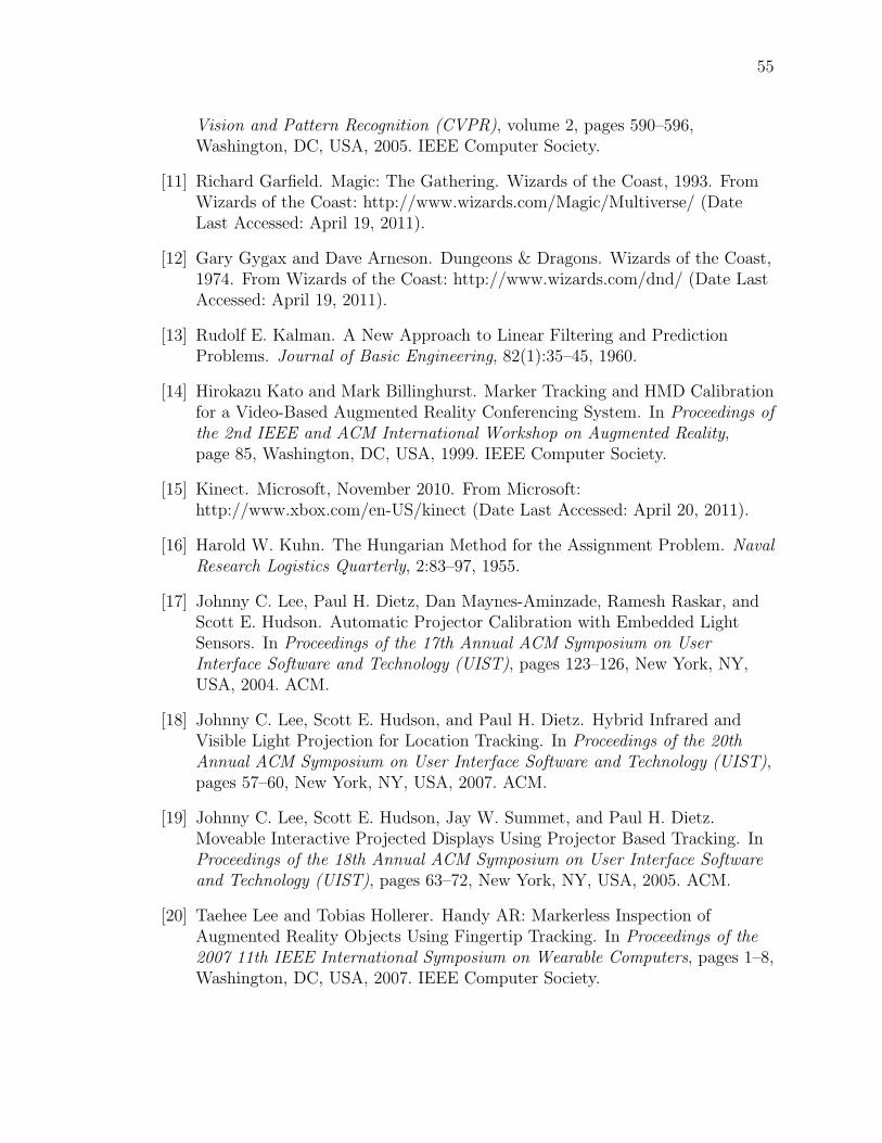
55
Vision and Pattern Recognition (CVPR), volume 2, pages 590–596,Washington, DC, USA, 2005. IEEE Computer Society.
[11] Richard Garfield. Magic: The Gathering. Wizards of the Coast, 1993. FromWizards of the Coast: http://www.wizards.com/Magic/Multiverse/ (DateLast Accessed: April 19, 2011).
[12] Gary Gygax and Dave Arneson. Dungeons & Dragons. Wizards of the Coast,1974. From Wizards of the Coast: http://www.wizards.com/dnd/ (Date LastAccessed: April 19, 2011).
[13] Rudolf E. Kalman. A New Approach to Linear Filtering and PredictionProblems. Journal of Basic Engineering, 82(1):35–45, 1960.
[14] Hirokazu Kato and Mark Billinghurst. Marker Tracking and HMD Calibrationfor a Video-Based Augmented Reality Conferencing System. In Proceedings ofthe 2nd IEEE and ACM International Workshop on Augmented Reality,page 85, Washington, DC, USA, 1999. IEEE Computer Society.
[15] Kinect. Microsoft, November 2010. From Microsoft:http://www.xbox.com/en-US/kinect (Date Last Accessed: April 20, 2011).
[16] Harold W. Kuhn. The Hungarian Method for the Assignment Problem. NavalResearch Logistics Quarterly, 2:83–97, 1955.
[17] Johnny C. Lee, Paul H. Dietz, Dan Maynes-Aminzade, Ramesh Raskar, andScott E. Hudson. Automatic Projector Calibration with Embedded LightSensors. In Proceedings of the 17th Annual ACM Symposium on UserInterface Software and Technology (UIST), pages 123–126, New York, NY,USA, 2004. ACM.
[18] Johnny C. Lee, Scott E. Hudson, and Paul H. Dietz. Hybrid Infrared andVisible Light Projection for Location Tracking. In Proceedings of the 20thAnnual ACM Symposium on User Interface Software and Technology (UIST),pages 57–60, New York, NY, USA, 2007. ACM.
[19] Johnny C. Lee, Scott E. Hudson, Jay W. Summet, and Paul H. Dietz.Moveable Interactive Projected Displays Using Projector Based Tracking. InProceedings of the 18th Annual ACM Symposium on User Interface Softwareand Technology (UIST), pages 63–72, New York, NY, USA, 2005. ACM.
[20] Taehee Lee and Tobias Hollerer. Handy AR: Markerless Inspection ofAugmented Reality Objects Using Fingertip Tracking. In Proceedings of the2007 11th IEEE International Symposium on Wearable Computers, pages 1–8,Washington, DC, USA, 2007. IEEE Computer Society.
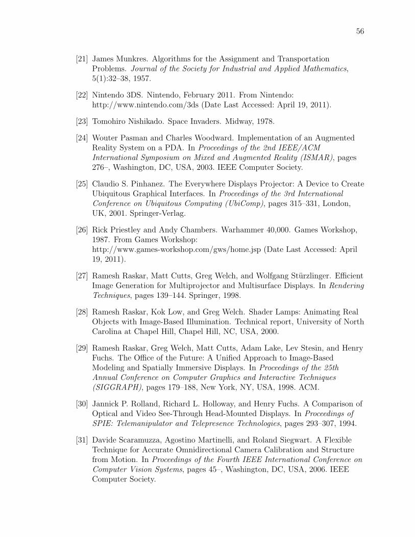
56
[21] James Munkres. Algorithms for the Assignment and TransportationProblems. Journal of the Society for Industrial and Applied Mathematics,5(1):32–38, 1957.
[22] Nintendo 3DS. Nintendo, February 2011. From Nintendo:http://www.nintendo.com/3ds (Date Last Accessed: April 19, 2011).
[23] Tomohiro Nishikado. Space Invaders. Midway, 1978.
[24] Wouter Pasman and Charles Woodward. Implementation of an AugmentedReality System on a PDA. In Proceedings of the 2nd IEEE/ACMInternational Symposium on Mixed and Augmented Reality (ISMAR), pages276–, Washington, DC, USA, 2003. IEEE Computer Society.
[25] Claudio S. Pinhanez. The Everywhere Displays Projector: A Device to CreateUbiquitous Graphical Interfaces. In Proceedings of the 3rd InternationalConference on Ubiquitous Computing (UbiComp), pages 315–331, London,UK, 2001. Springer-Verlag.
[26] Rick Priestley and Andy Chambers. Warhammer 40,000. Games Workshop,1987. From Games Workshop:http://www.games-workshop.com/gws/home.jsp (Date Last Accessed: April19, 2011).
[27] Ramesh Raskar, Matt Cutts, Greg Welch, and Wolfgang Sturzlinger. EfficientImage Generation for Multiprojector and Multisurface Displays. In RenderingTechniques, pages 139–144. Springer, 1998.
[28] Ramesh Raskar, Kok Low, and Greg Welch. Shader Lamps: Animating RealObjects with Image-Based Illumination. Technical report, University of NorthCarolina at Chapel Hill, Chapel Hill, NC, USA, 2000.
[29] Ramesh Raskar, Greg Welch, Matt Cutts, Adam Lake, Lev Stesin, and HenryFuchs. The Office of the Future: A Unified Approach to Image-BasedModeling and Spatially Immersive Displays. In Proceedings of the 25thAnnual Conference on Computer Graphics and Interactive Techniques(SIGGRAPH), pages 179–188, New York, NY, USA, 1998. ACM.
[30] Jannick P. Rolland, Richard L. Holloway, and Henry Fuchs. A Comparison ofOptical and Video See-Through Head-Mounted Displays. In Proceedings ofSPIE: Telemanipulator and Telepresence Technologies, pages 293–307, 1994.
[31] Davide Scaramuzza, Agostino Martinelli, and Roland Siegwart. A FlexibleTechnique for Accurate Omnidirectional Camera Calibration and Structurefrom Motion. In Proceedings of the Fourth IEEE International Conference onComputer Vision Systems, pages 45–, Washington, DC, USA, 2006. IEEEComputer Society.
57
[32] Andreas Seyfarth. Puerto Rico. Rio Grande Games, 2002. From Rio GrandeGames: http://www.riograndegames.com/games.html?id=4 (Date LastAccessed: April 19, 2011).
[33] Yu Sheng, Theodore C. Yapo, Christopher Young, and Barbara Cutler.Virtual Heliodon: Spatially Augmented Reality for Architectural DaylightingDesign. In IEEE Virtual Reality Conference (VR), pages 63–70, Washington,DC, USA, 2009. IEEE Computer Society.
[34] Jamie Shotton, Andrew Fitzgibbon, Mat Cook, Toby Sharp, Mark Finocchio,Richard Moore, Alex Kipman, and Andrew Blake. Real-Time Human PoseRecognition in Parts from Single Depth Images. In Proceedings of the 2011IEEE Computer Society Conference on Computer Vision and PatternRecognition (CVPR) (to appear), Washington, DC, USA, June 2011. IEEEComputer Society.
[35] Ivan E. Sutherland. A Head-Mounted Three Dimensional Display. InProceedings of the Fall Joint Computer Conference, Part I (AFIPS), pages757–764, New York, NY, USA, December 1968. ACM.
[36] Klaus Teuber. The Settlers of Catan. Mayfair Games, 1955. From MayfairGames: http://www.catan.com/ (Date Last Accessed: April 19, 2011).
[37] John Underkoffler, Brygg Ullmer, and Hiroshi Ishii. Emancipated Pixels:Real-World Graphics in the Luminous Room. In Proceedings of the 26thAnnual Conference on Computer Graphics and Interactive Techniques(SIGGRAPH), pages 385–392, New York, NY, USA, 1999. ACMPress/Addison-Wesley Publishing Co.
[38] Daniel Wagner and Dieter Schmalstieg. First Steps Towards HandheldAugmented Reality. In Proceedings of the 7th IEEE International Symposiumon Wearable Computers (ISWC), pages 127–, Washington, DC, USA, 2003.IEEE Computer Society.
[39] Robert Y. Wang and Jovan Popovic. Real-Time Hand-Tracking with a ColorGlove. In Proceedings of the 36th Annual Conference on Computer Graphicsand Interactive Techniques (SIGGRAPH), pages 63:1–63:8, New York, NY,USA, 2009. ACM.
[40] John Weaver. Kuhn-Munkres implementation, 2007. From GitHub:https://github.com/saebyn/munkres-cpp (Date Last Accessed: February 14,2011).
[41] Jordan Weisman and Kevin Barrett. Mage Knight. WizKids, Inc. FromWizKids, Inc. : http://wizkidsgames.com/mageknight/ (Date Last Accessed:April 19, 2011).

58
[42] Theodore C. Yapo, Yu Sheng, Joshua Nasman, Andrew Dolce, Eric Li, andBarbara Cutler. Dynamic Projection Surfaces for Immersive Visualization. InProceedings of IEEE International Workshop on Projector-Camera Systems(PROCAMS), Washington, DC, USA, 2010. IEEE Computer Society.
[43] Zhengyou Zhang. A Flexible New Technique for Camera Calibration. IEEETransactions on Pattern Analysis and Machine Intelligence,22(11):1330–1334, November 2000.