multi-field responsive origami structures: … · the use of origami principles to create...
TRANSCRIPT
Proceedings of the ASME 2013 International Design Engineering Technical Conferences & Computers and Information in Engineering Conference
IDETC/CIE 2013 August 4-7, 2013, Portland, Oregon, USA
DETC2013-12405
MULTI-FIELD RESPONSIVE ORIGAMI STRUCTURES: PRELIMINARY MODELING AND EXPERIMENTS
Saad Ahmed,a Carlye Lauff,a Adrienne Crivaro,a Kevin McGough,a Robert Sheridan,b Mary Frecker,a* Paris von Lockette,b Zoubeida Ounaies,a Timothy Simpson,a Jyh-Ming Lien,c Rebecca Strzelecd
aDepartment of Mechanical and Nuclear Engineering
The Pennsylvania State University State College, PA 16801
*Contact email: [email protected]
bDepartment of Mechanical Engineering Rowan University
Glassboro, NJ 08016
cDepartment of Computer Science George Mason University
Fairfax, VA 22030
dDivision of Arts and Humanities The Pennsylvania State University, Altoona Campus
Altoona, PA 16601
ABSTRACT
The use of origami principles to create 3-dimensional shapes has the potential to revolutionize active material structures and compliant mechanisms. Active origami structures can be applied to a broad range of areas such as reconfigurable aircraft and deployable space structures as well as instruments for minimally invasive surgery. Our current research is focused on dielectric elastomer (DE) and magneto active elastomer (MAE) materials to create multi-field responsive structures. Such multi-field responsive structures will integrate the DE and MAE materials to enable active structures that fold/unfold in different ways in response to electric and/or magnetic field. They can also unfold either as a result of eliminating the applied field or in response to the application of an opposite field. This concept is demonstrated in a folding cube shape and induced locomotion in the MAE material. Two finite element models are developed for both the DE and MAE materials and validated through physical testing of these materials. The models are then integrated to demonstrate multi-field responses of a bi-fold multi-field responsive structure. The bifold model is designed to fold about one axis in an electric field and a perpendicular axis in a magnetic field. Future modeling efforts and research directions are also discussed based on these preliminary results.
NOMENCLATURE Si, S1, S2, S3 Shapes due to applied fields σ Maxwell stress V Applied voltage t Thickness r Relative dielectric permittivity ε0 Permittivity of free space H Magnetic field magnitude α1, α2, µ1, µ2 Ogden parameters G Shear modulus
Gradient operator Cauchy stress
H Magnetic field vector B Magnetic induction U Strain energy density
I1, I2 First and second principle stretch invariants J Jacobian matrix
Dielectric stress Uniaxial (Cauchy) stress
C10, C01 Mooney Rivlin constants Kronecker delta
Magnetic Permittivity of free space Remanent magnetization
Density θ Fold angle R2 Coefficient of determination tc MAE cantilever thickness
MAE cantilever length
/ MAE / PDMS folding composite thickness
/ MAE / PDMS folding composite width MAE folding composite length PDMS folding composite length
s MAE folding composite spacing tc MAE cantilever thickness Vhi Voltage difference L Length of composite rDE Radius of fold line for DE rDE offset Offset of fold lone radius for DE rMAE Radius of fold line for MAE rMAE offset Offset of fold line radius for MAE EMAE Young’s modulus of MAE EDE Young’s modulus of DE EUL Young’s modulus of underlayer r,DE Relative permittivity of DE w1 Width of DE strips w2 Width of MAE strips t1 Active layer thickness t2 Underlayer thickness ρDE DE density
ρMAE MAE density
m Mass of active material Avector potential Magnetic vector potential Vdifference Applied voltage INTRODUCTION
The use of origami principles to create three-dimensional shapes has the potential to revolutionize active material structures and compliant mechanisms. Origami principles can be applied to a broad range of areas such as reconfigurable aircraft and deployable space structures as well as instruments for minimally invasive surgery. Our research goal is to accomplish rigorous design of multi-field origami structures using compliant mechanisms and active materials. These origami structures respond to multiple physical stimuli and will be realized through development of new nano- and micro-enabled active materials and rigorous design of active compliant mechanisms. The multi-field responsive origami structures are designed to self-assemble (by folding) and self-disassemble (by unfolding). This ability to actively fold and unfold is in contrast to state-of-the-art active origami structures that must be manually unfolded [1]. An example of a multi-field self-assembling and self-disassembling origami structure is illustrated in Figure 1, where the active structure is capable of folding from an initial shape Si (flat sheet) to shape S1 (stair step) due to an magnetic field, to shape S2 (accordion) due to an electric field, and to shape S3 (complex 3D shape [2]) due to a thermal field. It can also actively unfold from any shape Sj back to the flat sheet Si, either as a result of eliminating the applied field or in response to application of an opposite field.
A key component to accomplishing our research goal is
development of integrated active materials for on-demand folding and unfolding. This approach is in contrast to current efforts where discrete actuators, such as shape memory alloys or piezoelectric patches, are added to enable structures to deform or reconfigure into particular shapes [3-6]. Similarly, the few references that discuss programmable matter also employ similar discrete actuators, either affixed or in some cases embedded in the structure [1, 7], which add weight and complexity and limit scalability. Previous compliant mechanism design approaches have focused on multifunctionality in response to mechanical actuation to a limited extent [8-12] and on morphing structures with small and large deformation [13-15], some with discrete active material actuators [16, 17], but none have considered folding structures or multi-field responses directly.
In this work, we focus on dielectric elastomer (DE) and magneto active elastomer (MAE) materials to create multi-field responsive structures. We first demonstrate bending actuation using DE and MAE separately, and then report our efforts to elevate the deformation of each from bending to folding, and finally introduce our concept of realizing a multi-field actuated structure using a bifold constructed from both MAE and DE materials.
Dielectric elastomers are polymers that exhibit coupling between mechanical and electrical fields; resulting electromechanical strains can reach over 300% [18-22] . DEs are extremely promising as active materials because of their high specific elastic energy density (3.4 J/g), large strain response (>300%), rapid response (< 1 ms), moderate stress (up to 8 MPa), and high electromechanical
coupling efficiency (60-90%) [20, 23-29]. A DE can be thought of as a compliant capacitor, where the actuation mechanism takes advantage of the low modulus and high breakdown electric field of the material. As shown in Figure 2, the DE is generally coated with a compliant electrode on both sides, and a high voltage is applied. As a result of the voltage, opposite charges form at the electrodes, giving rise to electrostatic forces which compress and squeeze the film (Figure 2); compression of the film thickness brings opposite charges of two electrodes close together, and the planar stretching of the film separates similar charges of same electrode.
Volume conservation forces the elastomer to expand transversely to the electric field direction by increasing the area of the electrodes. The electrostatic pressure across the electrode is given by the Maxwell stress σ. The Maxwell stress σ acting on the elastomer film can be calculated for a given applied voltage V and film thickness t by Equation 1 [30] ,
σ = r ε0 (1)
where r is the relative dielectric permittivity of the material, and ε0 is the permittivity of free space (8.854 10 / ).
To date most scientific research has focused on the actuation mode based on planar expansion or area change of DE; the planar actuator can be easily built using the commercially available acrylic material 3M VHB 4905 and 3M VHB 4910, and has a proven track record of demonstrating very high deformations when pre-strained [19, 23, 24, 30, 31] . Although the concept of a DE bender is not new, and there is evidence of theoretical and modeling work mentioning this configuration [23, 30], the need for pre-stress in DE materials has prevented the experimental realization of DE-based benders to date. In fact, the most widely used DE samples are 3M VHB 4905/4910, which require large pre-strain to demonstrate significant actuation. However, the last two years have seen a small number of studies utilizing a new thinner DE material based on 3M VHB (F9460PC, F9469PC, F9473PC), which enables configuring DE as unimorph and bimorph bender actuators [32-35] .
Finite element analysis investigating electromechanical coupling has been performed for planar DE actuators [36]. Typically however, previous finite element modeling of DE-based actuators, both planar [37-39] and bending [40], are non-coupled (i.e., purely mechanical) and apply pressure loads to simulate the induced Maxwell stress. When calculating the Maxwell stress, it can be assumed that the DE thickness remains constant while undergoing deformation [40]. However, this assumption neglects the increase in Maxwell stress as the thickness of the DE decreases during the deformation. To improve the application of Equation 1, efforts have been made to account for the change in thickness of the DE as it contracts under the application of Maxwell stress [37, 38]. Several constitutive models have been used to describe the hyperelastic behavior of a given dielectric elastomer, including the Ogden [38, 39, 41], Arruda-Boyce [38, 40, 42], and Yeoh [38, 43] models.
Magneto-active elastomers, also termed magneto-rheological elastomers (MREs) owing to their roots in MR fluids, are
Figure 1: A CONCEPT FOR A MULTI-FIELD RESPONSIVEORIGAMI STRUCTURE THAT ACTIVELY FOLDS FROM ANINITIALLY FLAT SHEET TO COMPLEX THREE-DIMENSIONAL SHAPES IN RESPONSE TO DIFFERENTAPPLIED FIELDS. IT IS ALSO CAPABLE OF ACTIVELYUNFOLDING FROM ANY SHAPE BACK TO THE FLATSHEET.
Figure 2: PRINCIPLE OF OPERATION OF DE.
comprised of ferromagnetic particles embedded in an elastomer matrix. Their initial technological importance stemmed from the relative increase in the material’s shear stiffness in the presence of moderate magnetic fields ( 1 3 ) with respect to the zero-field stiffness, the so-called MR effect. Reported values to date range from 60 – 300% depending on the initial stiffness of the matrix and the field strengths used [44-53]. Most work on MAEs use carbonyl iron, a roughly spherical form of the element easily available in a large range of sizes with useful particle sizes ranging from 100nm through 100s of micrometers [44-53].
Though a number of studies have engaged the problem of modeling MAEs in the context of soft-magnetic filler materials, none have addressed similar concerns in systems comprised of hard-magnetic filler particles. This oversight has largely occurred since experimental investigations have only recently addressed the novel behaviors exhibited by hard-magnetic MAEs, which include large deformation transverse bending in cantilevers and in-plane shearing actuations in flat sheets, both from the undeformed state – behavior of which soft-magnetic carbonyl (spherical) iron materials are incapable [54-57].
In previous theoretical and computational work [58-70], simplifying assumptions required to generate tractable problems have excluded hard-magnetic torque-generating behavior as a necessary step to produce closed-form relationships. Moreover, most studies failed to address the role of demagnetizing effects, the interaction the local field produced by the magnetic material has with the external field, and the magnetic material around it. Finally, most prior work modeling MAEs has focused on microstructure-property relationships. While microstructure-property relationships of soft-magnetic MAE materials are an important materials science issue, this work examines a larger length-scale, focusing on generating a framework for predictions of the macroscopic response for devices that are driven in part by hard-magnetic MAE materials. The problem, necessarily, requires descriptions of material properties but may do so at the macroscopic level. Additionally, while particle-particle interactions caused by particle-level demagnetizing fields are below the length-scale lens of this work, the bulk geometry of the device in conjunction with magnetization behavior of the embedded MAE materials, generates a macro-scale demagnetizing field that must be accounted for since it disrupts the local field seen by the device itself.
The remainder of the paper is organized in the following manner. The use of DE and MAE as bender actuators is described, including both the finite element modeling and related experimental validation. Next, our efforts in evolving from bending to folding in both DE- and MAE-based structures is presented, followed by two proof-of-concept demonstrations for 3D folding using MAE. Both DE and MAE are then integrated into one finite element analysis model to show multi-field responses of a bi-fold structure. Finally, we describe future modeling efforts and research directions. BENDING ACTUATION USING DE AND MAE
In this section, we explore different approaches to achieving large bending actuation driven by DE and MAE actuators, and present modeling of benders and related experimental validation. DE Bender
Finite element modeling of DE bender. Finite element analysis (FEA) of the DE bender was performed using the commercially available multi-physics finite element software package COMSOL Multiphysics [71]. Use of this software package is preferred because it is capable of solving coupled electromechanical models, which will be developed in future studies. Material properties for the DE were based on the commercially available 3M VHB 4905/4910. The three-term Ogden model is used to describe the hyperelastic behavior of the DE. The values of the Ogden parameters α1, α2, α3, µ1, µ2 and µ3 are 1.293, 2.3252, 2.561, 0.00858 MPa, 0.0843 MPa, and -0.0233 MPa, respectively [38]. For
a hyperelastic material described by the Ogden model, the shear modulus G at small strain can be expressed in terms of the Odgen parameters, as in Equation 2,
∑ μ (2)
where N is the number of terms used for the Ogden model [72]. Equation 2 yields a shear modulus of 0.0737 MPa for the DE. The present work sets forth that the incompressibility of the DE can be modeled by assuming that the initial bulk modulus of the DE, which is a required input for COMSOL, to six orders of magnitude higher than the shear modulus. The initial bulk modulus determines how strongly incompressibility is enforced. The density of the DE is set equal to that of 3M VHB 4910, which is reported as 960 kg/m3 [73]. The substrate, 3M magic scotch tape in this example, is treated as linear elastic, and its modulus of elasticity is experimentally determined to be 1.6 GPa. The density of the substrate is experimentally determined to be 1063 kg/m3. The Poisson’s ratio of the substrate is assumed to be 0.3.
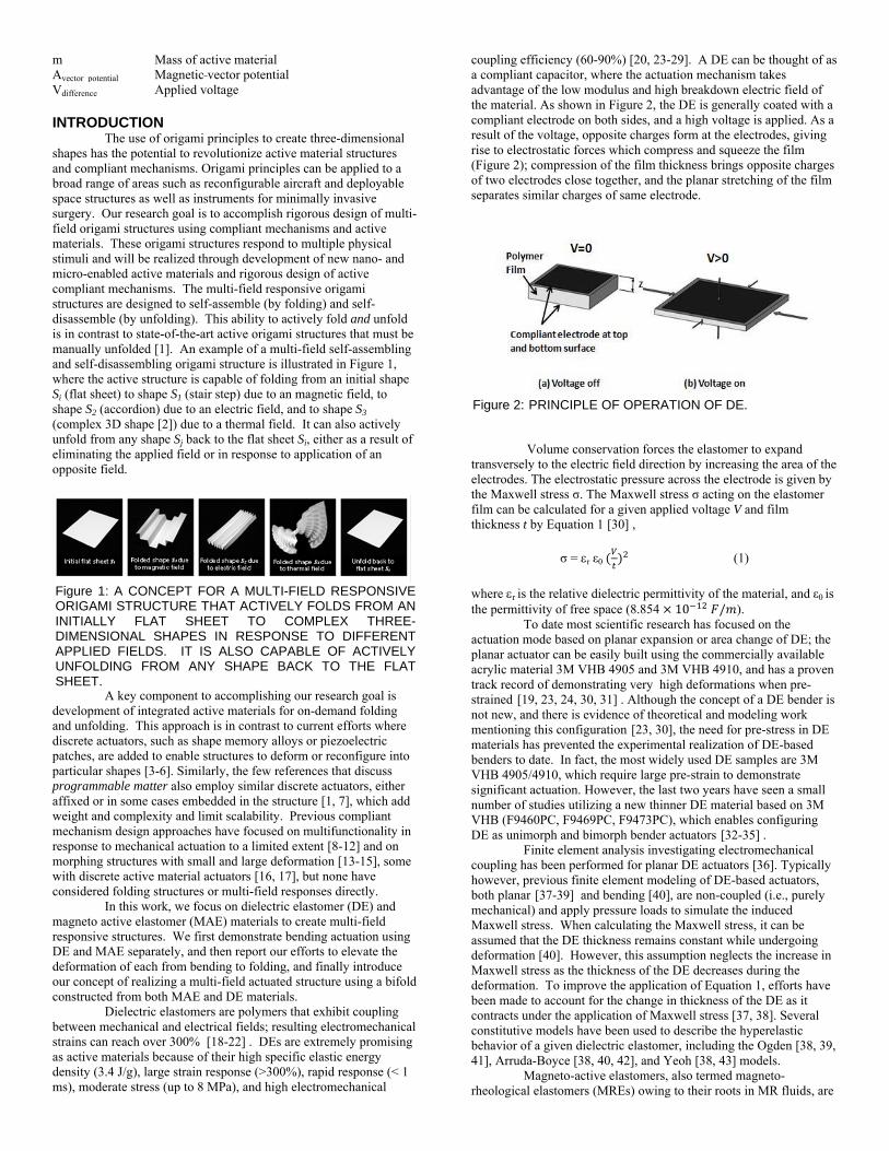
The model of the DE bender consists of four components (Figure 3). Components 1 (0.16368 cm x 5.5 cm x 0.75 cm), 2 (0.16368 cm x 0.5 cm x 0.75 cm), and 3 (0.16368 cm x 6.0 cm x 0.25 cm) are treated as the hyperelastic DE, while Component 4 (0.031 cm x 6.0 cm x 0.95 cm) is treated as the linear elastic substrate. The thickness of the DE components (0.16368 cm) is used to model the six layers of the DE as a single layer bulk material. Similarly, the thickness (0.031 cm) of the substrate component is selected to model the 5 layers of 3M magic scotch tape as a single layer bulk material. To simulate the individual DE components as a single entity, continuity conditions are applied to the mutual faces shared by 1, 2, and 3. To simulate a connection between the DE and substrate along the areas where the compliant electrode is not present, continuity conditions are applied to the mutual face of 3 and 4 and the mutual face of 2 and 4. Where the compliant electrode is present between the DE and substrate, there is no connection between the materials because the compliant electrode will not allow the DE to adhere to the substrate. For this reason, a frictionless contact condition is applied to the mutual face of 1 and 4. A fixed boundary condition is applied to the faces of 1, 3, and 4 with their normal vector oriented in the negative y-direction. A symmetry boundary condition is applied to the faces of 1, 2, and 4 with their normal vector oriented in the negative z-direction. To simulate the effect of the Maxwell stress, uniform pressure loads (dielectric pressure) are applied to the large faces of 1. One of these faces is indicated on 1 in blue in Figure 3. The dielectric pressure is set equal to half the Maxwell stress, which means the sum of the dielectric pressures will cause a stress in 1 equal to the Maxwell stress. For the calculation of the Maxwell stress, the material thickness used in Equation 1 is set equal to the thickness of one of the six DE layers (272.8 µm). By doing so, the induced Maxwell stress experienced by the bulk 1 will be equivalent to the Maxwell stress induced in each individual layer. Due to the large expected deformation of the DE bender, it is necessary to ensure any load placed on the bender is aligned with a material’s local coordinate system. When large deformation is expected, it should be noted that a geometric nonlinearity feature, which alters stress-strain relationships, must be implemented.
The model is meshed utilizing the predefined extra fine element size of the tetrahedral element meshing feature to yield 33,010 total elements. The model simulates applied voltages ranging from 100 V to 4000 V in 100 V increments. The resulting magnitude of tip displacement in the x- and y-directions is studied as a function of the nominal electric field. Nominal electric field is calculated by dividing the applied voltage by the nominal initial thickness of a single layer of dielectric elastomer. The resultant tip displacement is then normalized with respect to length of the DE bender (6 cm) for comparison between the finite element model and experimental analysis. Simulations with an applied voltage greater than 4000 V were found to encounter convergence difficulties. It is believed the convergence difficulties resulted from the large deformation
experienced by the DE bender and the strong enforcement of DE incompressibility.
Figure 3: FINITE ELEMENT ANALYSIS MODEL OF THE DIELECTRIC BENDER CONSISTING OF DIELECTRIC ELASTOMER COMPONENTS (LABELED 1, 2, AND 3) AND A SUBSTRATE COMPONENT (LABELED 4). THE FACE SHOWN IN BLUE INDICATES ONE OF THE TWO FACES THAT THE DIELECTRIC PRESSURE ACTS ON.
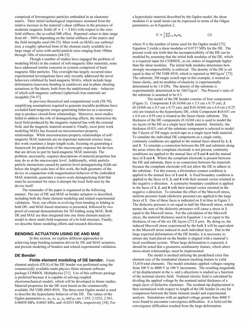
Experimental validation of DE bender. 3M VHB (F9473PC) elastomer was chosen due to its high dielectric constant (4.7), low thickness (272.8 µm), very low young’s modulus (0.19MPa), and adhesive surface. Carbon conductive grease (MG Chemicals) was chosen as compliant electrode due to its outstanding electrical conductivity and great tolerance and compliance to large strain. 3M magic scotch tape was selected as the passive substrate because it is a good electrical insulator, very thin (62µm thick), and has very high young’s modulus (1.6GPa) compared to DE layers. The bending actuator consists of three major portions: active material (DE), substrate (scotch tape) and compliant electrodes (carbon grease) as shown in Figure 4.
Rectangular DE samples of 6cmx2cm are cut, carbon grease is manually painted on a 5.5cm 1.5cm area and a long narrow aluminum foil is attached to the edge of the electrode to create an external terminal. Then the substrate is cut from 3M magic scotch tape in 6cm 1.9cm size and attached to the DE containing carbon grease. The paper liner from the other side of the DE sample is removed, and carbon grease is again manually applied. Then a new DE sample is stacked on top of the previous one, and the adhered layers are pressed together manually for good inter layer bonding. Afterwards, the paper liner of this DE sample is again removed to expose the sticky side of the sample and to paint carbon grease on it. Subsequently, a total of six DE layers are stacked one on top of one another to fabricate the bending actuator. In between the steps of layer-to-layer stacking, aluminum foils are attached to the alternative position of each stack to separate positive and negative electrodes.
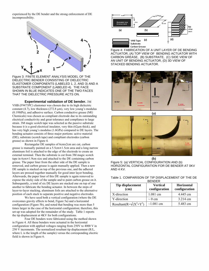
We have used both a vertical configuration (where the DE overcomes gravity effects to bend, Figure 5a) and a horizontal configuration (Figure 5b), and noted that bending was more than 5 times larger in the case of the horizontal configuration; therefore, this set-up was adopted for the remainder of the study. Table 1 reports the tip displacement at 4KV for both configurations. Four DE benders were fabricated using the method shown in Figure 4. All these benders were actuated in the horizontal configuration with applied voltages ranging from 250V to 4000 V in 250 V increments. The normalized resultant tip displacement (R/L, where L is the length of the sample) versus the corresponding electric field is shown in Figure 6.
Figure 4: FABRICATION OF A UNIT LAYER OF DE BENDING ACTUATOR, (A) TOP VIEW OF BENDING ACTUATOR WITH CARBON GREASE, (B) SUBSTRATE, (C) SIDE VIEW OF AN UNIT OF BENDING ACTUATOR, (D) 3D VIEW OF STACKED BENDING ACTUATOR.
(a)
(b)
Figure 5: (a) VERTICAL CONFIGURATION AND (b) HORIZONTAL CONFIGURATION FOR DE BENDER AT 0KV AND 4 KV.
Table 1. COMPARISON OF TIP DISPLACEMENT OF THE DE
BENDER Tip displacement
(cm) Vertical
configuration Horizontal
configuration
X-direction 1.081 cm 4.445 cm Y-direction ~ 0 cm 3.214 cm
Resultant(R=√(X2+Y2) ~1.081 cm 5.483 cm
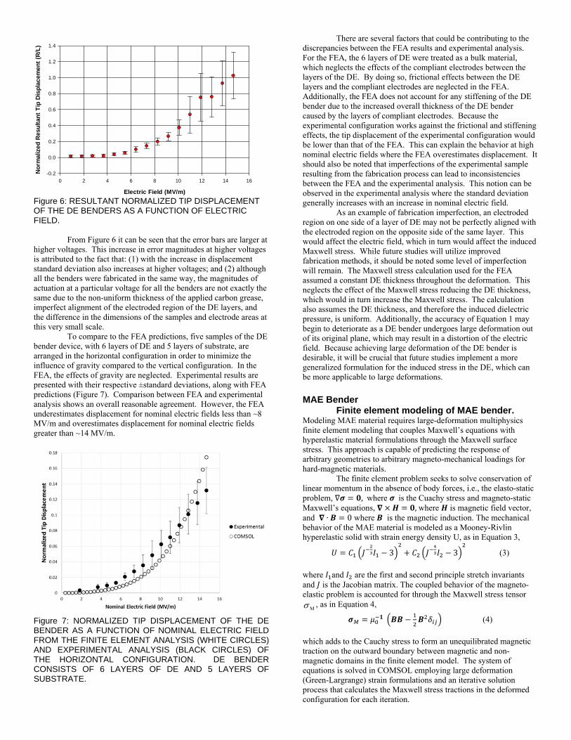
Figure 6: RESULTANT NORMALIZED TIP DISPLACEMENT OF THE DE BENDERS AS A FUNCTION OF ELECTRIC FIELD.
From Figure 6 it can be seen that the error bars are larger at higher voltages. This increase in error magnitudes at higher voltages is attributed to the fact that: (1) with the increase in displacement standard deviation also increases at higher voltages; and (2) although all the benders were fabricated in the same way, the magnitudes of actuation at a particular voltage for all the benders are not exactly the same due to the non-uniform thickness of the applied carbon grease, imperfect alignment of the electroded region of the DE layers, and the difference in the dimensions of the samples and electrode areas at this very small scale.
To compare to the FEA predictions, five samples of the DE bender device, with 6 layers of DE and 5 layers of substrate, are arranged in the horizontal configuration in order to minimize the influence of gravity compared to the vertical configuration. In the FEA, the effects of gravity are neglected. Experimental results are presented with their respective ±standard deviations, along with FEA predictions (Figure 7). Comparison between FEA and experimental analysis shows an overall reasonable agreement. However, the FEA underestimates displacement for nominal electric fields less than ~8 MV/m and overestimates displacement for nominal electric fields greater than ~14 MV/m.
Figure 7: NORMALIZED TIP DISPLACEMENT OF THE DE BENDER AS A FUNCTION OF NOMINAL ELECTRIC FIELD FROM THE FINITE ELEMENT ANALYSIS (WHITE CIRCLES) AND EXPERIMENTAL ANALYSIS (BLACK CIRCLES) OF THE HORIZONTAL CONFIGURATION. DE BENDER CONSISTS OF 6 LAYERS OF DE AND 5 LAYERS OF SUBSTRATE.
There are several factors that could be contributing to the discrepancies between the FEA results and experimental analysis. For the FEA, the 6 layers of DE were treated as a bulk material, which neglects the effects of the compliant electrodes between the layers of the DE. By doing so, frictional effects between the DE layers and the compliant electrodes are neglected in the FEA. Additionally, the FEA does not account for any stiffening of the DE bender due to the increased overall thickness of the DE bender caused by the layers of compliant electrodes. Because the experimental configuration works against the frictional and stiffening effects, the tip displacement of the experimental configuration would be lower than that of the FEA. This can explain the behavior at high nominal electric fields where the FEA overestimates displacement. It should also be noted that imperfections of the experimental sample resulting from the fabrication process can lead to inconsistencies between the FEA and the experimental analysis. This notion can be observed in the experimental analysis where the standard deviation generally increases with an increase in nominal electric field.
As an example of fabrication imperfection, an electroded region on one side of a layer of DE may not be perfectly aligned with the electroded region on the opposite side of the same layer. This would affect the electric field, which in turn would affect the induced Maxwell stress. While future studies will utilize improved fabrication methods, it should be noted some level of imperfection will remain. The Maxwell stress calculation used for the FEA assumed a constant DE thickness throughout the deformation. This neglects the effect of the Maxwell stress reducing the DE thickness, which would in turn increase the Maxwell stress. The calculation also assumes the DE thickness, and therefore the induced dielectric pressure, is uniform. Additionally, the accuracy of Equation 1 may begin to deteriorate as a DE bender undergoes large deformation out of its original plane, which may result in a distortion of the electric field. Because achieving large deformation of the DE bender is desirable, it will be crucial that future studies implement a more generalized formulation for the induced stress in the DE, which can be more applicable to large deformations. MAE Bender
Finite element modeling of MAE bender. Modeling MAE material requires large-deformation multiphysics finite element modeling that couples Maxwell’s equations with hyperelastic material formulations through the Maxwell surface stress. This approach is capable of predicting the response of arbitrary geometries to arbitrary magneto-mechanical loadings for hard-magnetic materials.
The finite element problem seeks to solve conservation of linear momentum in the absence of body forces, i.e., the elasto-static problem, , where is the Cuachy stress and magneto-static Maxwell’s equations, ,where is magnetic field vector, and ∙ 0 where is the magnetic induction. The mechanical behavior of the MAE material is modeled as a Mooney-Rivlin hyperelastic solid with strain energy density U, as in Equation 3,
3 3 (3)
where and are the first and second principle stretch invariants and is the Jacobian matrix. The coupled behavior of the magneto-elastic problem is accounted for through the Maxwell stress tensor
M , as in Equation 4,
(4)
which adds to the Cauchy stress to form an unequilibrated magnetic traction on the outward boundary between magnetic and non-magnetic domains in the finite element model. The system of equations is solved in COMSOL employing large deformation (Green-Largrange) strain formulations and an iterative solution process that calculates the Maxwell stress tractions in the deformed configuration for each iteration.
Electric Field (MV/m)
0 2 4 6 8 10 12 14 16
No
rmal
ized
Res
ult
ant
Tip
Dis
pla
cem
ent
(R/L
)
-0.2
0.0
0.2
0.4
0.6
0.8
1.0
1.2
1.4
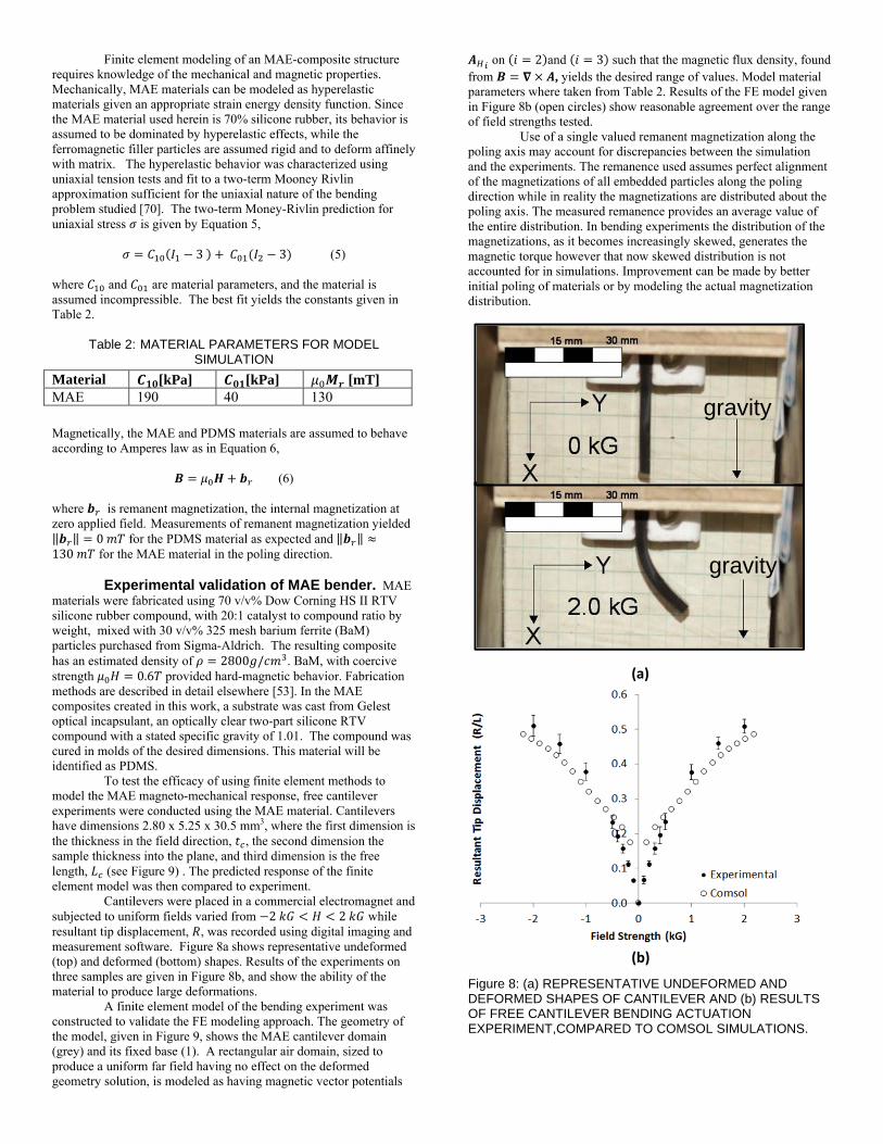
Finite element modeling of an MAE-composite structure requires knowledge of the mechanical and magnetic properties. Mechanically, MAE materials can be modeled as hyperelastic materials given an appropriate strain energy density function. Since the MAE material used herein is 70% silicone rubber, its behavior is assumed to be dominated by hyperelastic effects, while the ferromagnetic filler particles are assumed rigid and to deform affinely with matrix. The hyperelastic behavior was characterized using uniaxial tension tests and fit to a two-term Mooney Rivlin approximation sufficient for the uniaxial nature of the bending problem studied [70]. The two-term Money-Rivlin prediction for uniaxial stress is given by Equation 5,
3 3 (5)
where and are material parameters, and the material is assumed incompressible. The best fit yields the constants given in Table 2.
Table 2: MATERIAL PARAMETERS FOR MODEL SIMULATION
Magnetically, the MAE and PDMS materials are assumed to behave according to Amperes law as in Equation 6,
(6)
where is remanent magnetization, the internal magnetization at zero applied field. Measurements of remanent magnetization yielded ‖ ‖ 0 for the PDMS material as expected and ‖ ‖130 for the MAE material in the poling direction.
Experimental validation of MAE bender. MAE materials were fabricated using 70 v/v% Dow Corning HS II RTV silicone rubber compound, with 20:1 catalyst to compound ratio by weight, mixed with 30 v/v% 325 mesh barium ferrite (BaM) particles purchased from Sigma-Aldrich. The resulting composite has an estimated density of 2800 / . BaM, with coercive strength 0.6 provided hard-magnetic behavior. Fabrication methods are described in detail elsewhere [53]. In the MAE composites created in this work, a substrate was cast from Gelest optical incapsulant, an optically clear two-part silicone RTV compound with a stated specific gravity of 1.01. The compound was cured in molds of the desired dimensions. This material will be identified as PDMS.
To test the efficacy of using finite element methods to model the MAE magneto-mechanical response, free cantilever experiments were conducted using the MAE material. Cantilevers have dimensions 2.80 x 5.25 x 30.5 mm3, where the first dimension is the thickness in the field direction, , the second dimension the sample thickness into the plane, and third dimension is the free length, (see Figure 9) . The predicted response of the finite element model was then compared to experiment.
Cantilevers were placed in a commercial electromagnet and subjected to uniform fields varied from 2 2 while resultant tip displacement, , was recorded using digital imaging and measurement software. Figure 8a shows representative undeformed (top) and deformed (bottom) shapes. Results of the experiments on three samples are given in Figure 8b, and show the ability of the material to produce large deformations.
A finite element model of the bending experiment was constructed to validate the FE modeling approach. The geometry of the model, given in Figure 9, shows the MAE cantilever domain (grey) and its fixed base (1). A rectangular air domain, sized to produce a uniform far field having no effect on the deformed geometry solution, is modeled as having magnetic vector potentials
on 2 and 3 such that the magnetic flux density, found from , yields the desired range of values. Model material parameters where taken from Table 2. Results of the FE model given in Figure 8b (open circles) show reasonable agreement over the range of field strengths tested.
Use of a single valued remanent magnetization along the poling axis may account for discrepancies between the simulation and the experiments. The remanence used assumes perfect alignment of the magnetizations of all embedded particles along the poling direction while in reality the magnetizations are distributed about the poling axis. The measured remanence provides an average value of the entire distribution. In bending experiments the distribution of the magnetizations, as it becomes increasingly skewed, generates the magnetic torque however that now skewed distribution is not accounted for in simulations. Improvement can be made by better initial poling of materials or by modeling the actual magnetization distribution.
Figure 8: (a) REPRESENTATIVE UNDEFORMED AND DEFORMED SHAPES OF CANTILEVER AND (b) RESULTS OF FREE CANTILEVER BENDING ACTUATION EXPERIMENT,COMPARED TO COMSOL SIMULATIONS.
Material [kPa] [kPa] [mT] MAE 190 40 130
gravity
gravity
(a)
(b)
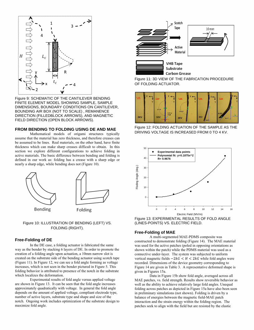
Figure 9: SCHEMATIC OF THE CANTILEVER BENDING FINITE ELEMENT MODEL SHOWING SAMPLE, SAMPLE DIMENSIONS, BOUNDARY CONDITIONS ON CANTILEVER, BOUNDING AIR BOX (NOT TO SCALE) , REMANENCE DIRECTION (FILLEDBLOCK ARROWS), AND MAGNETIC FIELD DIRECTION (OPEN BLOCK ARROWS). FROM BENDING TO FOLDING USING DE AND MAE
Mathematical models of origami structures typically assume that the material has zero thickness, and therefore creases can be assumed to be lines. Real materials, on the other hand, have finite thickness which can make sharp creases difficult to obtain. In this section we explore different configurations to achieve folding in active materials. The basic difference between bending and folding is defined in our work as: folding has a crease with a sharp edge or nearly a sharp edge, while bending does not (Figure 10).
Figure 10: ILLUSTRATION OF BENDING (LEFT) VS.
FOLDING (RIGHT). Free-Folding of DE
In the DE case, a folding actuator is fabricated the same way as the bender by stacking 6 layers of DE. In order to promote the creation of a folding angle upon actuation, a 10mm narrow slot is created on the substrate side of the bending actuator using scotch tape (Figure 11). In Figure 12, we can see a fold angle forming as voltage increases, which is not seen in the bender pictured in Figure 5. This folding behavior is attributed to presence of the notch in the substrate which localizes the deformation.
Experimental results of fold angle versus applied voltage are shown in Figure 13. It can be seen that the fold angle increases approximately quadratically with voltage. In general the fold angle depends on the amount of applied voltage, compliant electrode type, number of active layers, substrate type and shape and size of the notch. Ongoing work includes optimization of the substrate design to maximize fold angle.
Figure 11: 3D VIEW OF THE FABRICATION PROCEDURE OF FOLDING ACTUATOR.
Figure 12: FOLDING ACTUATION OF THE SAMPLE AS THE DRIVING VOLTAGE IS INCREASED FROM 0 TO 4 KV.
Figure 13: EXPERIMENTAL RESULTS OF FOLD ANGLE (LINES-POINTS) VS. ELECTRIC FIELD. Free-Folding of MAE
A multi-segmented MAE-PDMS composite was constructed to demonstrate folding (Figure 14). The MAE material was used for the active patches (poled in opposing orientations as shown within the patch) while the PDMS material was used as a connective under-layer. The system was subjected to uniform vertical magnetic fields 2 2 while fold angles were recorded. Dimensions of the device geometry corresponding to Figure 14 are given in Table 3. A representative deformed shape is given in Figures 15a.
Data in Figure 15b show fold angle, averaged across all MAE patches, vs. field strength. Results show reversible behavior as well as the ability to achieve relatively large fold angles. Unequal folding across patches as depicted in Figure 15a have also been seen in preliminary simulations (not shown). Folding is driven by a balance of energies between the magnetic field-MAE patch interaction and the strain energy within the folding region. The patches seek to align with the field but are resisted by the elastic
Electric Field (MV/m)
0 2 4 6 8 10 12 14 16
Flo
ding
Ang
le (
deg.
)
0
10
20
30
40
50
Experimental data pointsPolynomial fit: y=0.1875x^2R= 0.9676
2 4 x
y R
3
4
1
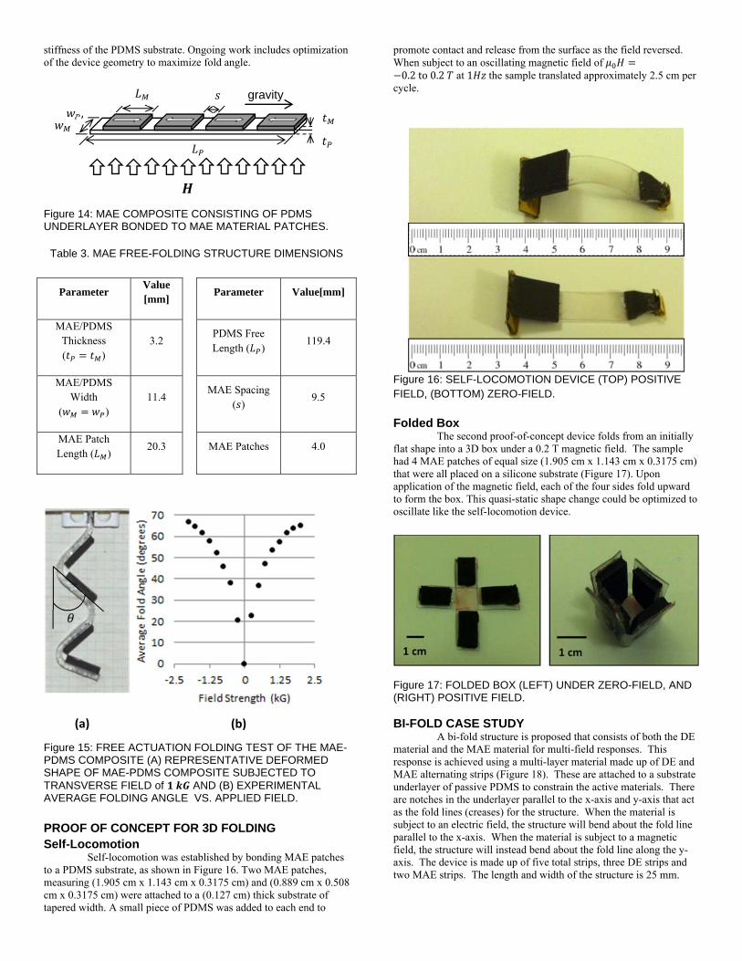
stiffness of the PDMS substrate. Ongoing work includes optimization of the device geometry to maximize fold angle.
Figure 14: MAE COMPOSITE CONSISTING OF PDMS UNDERLAYER BONDED TO MAE MATERIAL PATCHES.
Table 3. MAE FREE-FOLDING STRUCTURE DIMENSIONS
Parameter Value [mm]
Parameter Value[mm]
MAE/PDMS Thickness ( )
3.2 PDMS Free Length ( )
119.4
MAE/PDMS Width
( ) 11.4
MAE Spacing ( )
9.5
MAE Patch Length ( )
20.3 MAE Patches 4.0
Figure 15: FREE ACTUATION FOLDING TEST OF THE MAE-PDMS COMPOSITE (A) REPRESENTATIVE DEFORMED SHAPE OF MAE-PDMS COMPOSITE SUBJECTED TO TRANSVERSE FIELD of AND (B) EXPERIMENTAL AVERAGE FOLDING ANGLE VS. APPLIED FIELD.
PROOF OF CONCEPT FOR 3D FOLDING Self-Locomotion
Self-locomotion was established by bonding MAE patches to a PDMS substrate, as shown in Figure 16. Two MAE patches, measuring (1.905 cm x 1.143 cm x 0.3175 cm) and (0.889 cm x 0.508 cm x 0.3175 cm) were attached to a (0.127 cm) thick substrate of tapered width. A small piece of PDMS was added to each end to
promote contact and release from the surface as the field reversed. When subject to an oscillating magnetic field of 0.2to0.2 at 1 the sample translated approximately 2.5 cm per
cycle.
Figure 16: SELF-LOCOMOTION DEVICE (TOP) POSITIVE FIELD, (BOTTOM) ZERO-FIELD.
Folded Box
The second proof-of-concept device folds from an initially flat shape into a 3D box under a 0.2 T magnetic field. The sample had 4 MAE patches of equal size (1.905 cm x 1.143 cm x 0.3175 cm) that were all placed on a silicone substrate (Figure 17). Upon application of the magnetic field, each of the four sides fold upward to form the box. This quasi-static shape change could be optimized to oscillate like the self-locomotion device.
Figure 17: FOLDED BOX (LEFT) UNDER ZERO-FIELD, AND (RIGHT) POSITIVE FIELD. BI-FOLD CASE STUDY
A bi-fold structure is proposed that consists of both the DE material and the MAE material for multi-field responses. This response is achieved using a multi-layer material made up of DE and MAE alternating strips (Figure 18). These are attached to a substrate underlayer of passive PDMS to constrain the active materials. There are notches in the underlayer parallel to the x-axis and y-axis that act as the fold lines (creases) for the structure. When the material is subject to an electric field, the structure will bend about the fold line parallel to the x-axis. When the material is subject to a magnetic field, the structure will instead bend about the fold line along the y-axis. The device is made up of five total strips, three DE strips and two MAE strips. The length and width of the structure is 25 mm.
,
gravity
(a) (b)
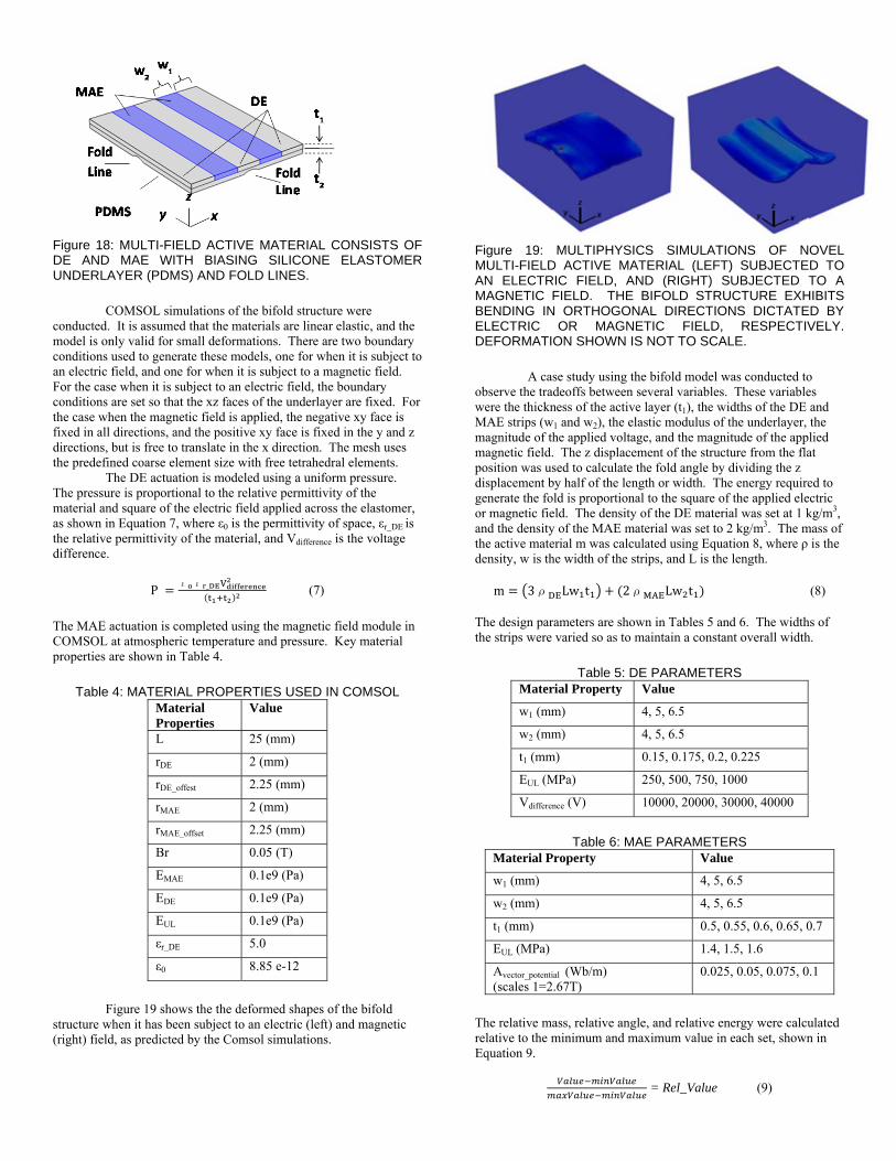
Figure 18: MULTI-FIELD ACTIVE MATERIAL CONSISTS OF DE AND MAE WITH BIASING SILICONE ELASTOMER UNDERLAYER (PDMS) AND FOLD LINES.
COMSOL simulations of the bifold structure were
conducted. It is assumed that the materials are linear elastic, and the model is only valid for small deformations. There are two boundary conditions used to generate these models, one for when it is subject to an electric field, and one for when it is subject to a magnetic field. For the case when it is subject to an electric field, the boundary conditions are set so that the xz faces of the underlayer are fixed. For the case when the magnetic field is applied, the negative xy face is fixed in all directions, and the positive xy face is fixed in the y and z directions, but is free to translate in the x direction. The mesh uses the predefined coarse element size with free tetrahedral elements.
The DE actuation is modeled using a uniform pressure. The pressure is proportional to the relative permittivity of the material and square of the electric field applied across the elastomer, as shown in Equation 7, where ε0 is the permittivity of space, εr_DE is the relative permittivity of the material, and Vdifference is the voltage difference.
Pε ε _ (7)
The MAE actuation is completed using the magnetic field module in COMSOL at atmospheric temperature and pressure. Key material properties are shown in Table 4.
Table 4: MATERIAL PROPERTIES USED IN COMSOL
Material Properties
Value
L 25 (mm)
rDE 2 (mm)
rDE_offest 2.25 (mm)
rMAE 2 (mm)
rMAE_offset 2.25 (mm)
Br 0.05 (T)
EMAE 0.1e9 (Pa)
EDE 0.1e9 (Pa)
EUL 0.1e9 (Pa)
εr_DE 5.0
ε0 8.85 e-12
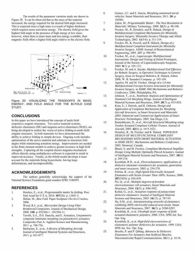
Figure 19 shows the the deformed shapes of the bifold
structure when it has been subject to an electric (left) and magnetic (right) field, as predicted by the Comsol simulations.
Figure 19: MULTIPHYSICS SIMULATIONS OF NOVEL MULTI-FIELD ACTIVE MATERIAL (LEFT) SUBJECTED TO AN ELECTRIC FIELD, AND (RIGHT) SUBJECTED TO A MAGNETIC FIELD. THE BIFOLD STRUCTURE EXHIBITS BENDING IN ORTHOGONAL DIRECTIONS DICTATED BY ELECTRIC OR MAGNETIC FIELD, RESPECTIVELY. DEFORMATION SHOWN IS NOT TO SCALE.
A case study using the bifold model was conducted to
observe the tradeoffs between several variables. These variables were the thickness of the active layer (t1), the widths of the DE and MAE strips (w1 and w2), the elastic modulus of the underlayer, the magnitude of the applied voltage, and the magnitude of the applied magnetic field. The z displacement of the structure from the flat position was used to calculate the fold angle by dividing the z displacement by half of the length or width. The energy required to generate the fold is proportional to the square of the applied electric or magnetic field. The density of the DE material was set at 1 kg/m3, and the density of the MAE material was set to 2 kg/m3. The mass of the active material m was calculated using Equation 8, where ρ is the density, w is the width of the strips, and L is the length.
m 3ρ Lw t 2ρ Lw t (8) The design parameters are shown in Tables 5 and 6. The widths of the strips were varied so as to maintain a constant overall width.
Table 5: DE PARAMETERS
Material Property Value
w1 (mm) 4, 5, 6.5
w2 (mm) 4, 5, 6.5
t1 (mm) 0.15, 0.175, 0.2, 0.225
EUL (MPa) 250, 500, 750, 1000
Vdifference (V) 10000, 20000, 30000, 40000
Table 6: MAE PARAMETERS
Material Property Value
w1 (mm) 4, 5, 6.5
w2 (mm) 4, 5, 6.5
t1 (mm) 0.5, 0.55, 0.6, 0.65, 0.7
EUL (MPa) 1.4, 1.5, 1.6
Avector_potential (Wb/m) (scales 1=2.67T)
0.025, 0.05, 0.075, 0.1
The relative mass, relative angle, and relative energy were calculated relative to the minimum and maximum value in each set, shown in Equation 9.
= Rel_Value (9)
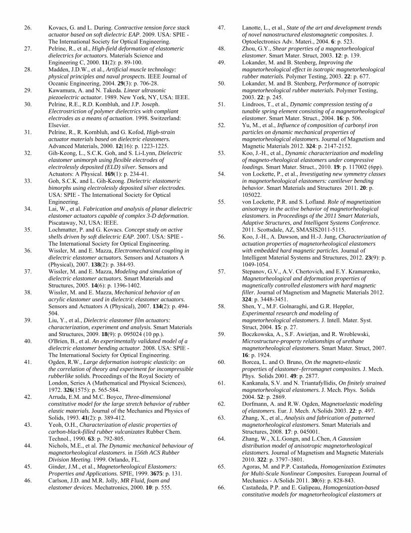
The results of the parameter variation study are shown in
Figure 20. It can be observed that as the mass of the material increased, the energy required for the desired fold angle increased. This is expected since a high mass is a result of higher thickness which requires more activation energy. The electric field gives the highest fold angle in the presence of high energy at low mass; however, when there is more mass and less energy available, then magnetic field offers a higher fold angle relative to the electric field.
Figure 20: VISUALIZING THE TRADEOFFS IN MASS, ENERGY, AND FOLD ANGLE FOR THE BI-FOLD CASE STUDY.
CONCLUSIONS In this paper we have introduced the concept of multi-field responsive origami structures. Two active material systems, dielectric elastomers (DE) and magneto-active elastomers (MAE), are being developed to realize the vision of active folding in multi-field origami structures. In both materials we have demonstrated the ability to achieve folding in simple devices. Ongoing work includes optimization of the active material and substrate to maximize fold angles while minimizing actuation energy. Improvements are needed in the finite element models to achieve greater accuracy at high field strengths. Capturing all the coupled electro-magneto-mechanical effects directly using multiphysics software is expected to result in improved accuracy. Finally, as the bifold model develops it must account for the materials being hyperelastic, having large deformations, and incompressibility. ACKNOWLEDGEMENTS The authors gratefully acknowledge the support of the National Science Foundation grant number EFRI 1240459.
REFERENCES
1. Hawkes, E., et al., Programmable matter by folding. Proc Natl Acad Sci U S A, 2010. 107(28): p. 12441-5.
2. Shlian, M., Bow Fold. Paper Sculpture 24x16x12 inches, 2006.
3. Wood, R.J., et al., Microrobot Design Using Fiber Reinforced Composites. Journal of Mechanical Design, 2008. 130: p. 052304-1 - 052304-11.
4. Tawfik, S.A., D.S. Dancila, and E. Armanios, Unsymmetric composite laminates morphing via piezoelectric actuators. Composites Part A: Applied Science and Manufacturing, 2011: p. 748-756.
5. Barbarino, S., et al., A Review of Morphing Aircraft. Journal of intelligent Material Systems and Structures, 2011: p. 823-877.
6. Gomez, J.C. and E. Garcia, Morphing unmanned aerial vehicles. Smart Materials and Structures, 2011. 20: p. 103001.
7. Zakin, M., Programmable Matter - The Next Revolution in Materials. Military Technology, 2008. 32(5): p. 98-100.
8. Frecker, M., R. Dziedzic, and R. Haluck, Design of Multifunctional Compliant Mechanisms for Minimally Invasive Surgery. Minimally Invasive Therapy and Allied Technologies, 2002. 11(5/6): p. 311-319.
9. Frecker, M., K. Powell, and R. Haluck, Design of a Multifunctional Compliant Instrument for Minimally Invasive Surgery. ASME Journal of Biomechanical Engineering, 2005. 127: p. 990-993.
10. Frecker, M., et al., Laparoscopic Multifunctional Instruments: Design and Testing of Initial Prototypes. Journal of the Society of Laparoendoscopic Surgeons, 2005. 9(1): p. 105-112.
11. Frecker, M. and A. Snyder, Multifunctional End Effectors for Robotic Surgery, in Operative Techniques in General Surgery, Issue on Surgical Robotics, R. Haluck, Editor 2006, W. B. Saunders Company. p. 165-169.
12. Aguirre, M. and M. Frecker. Design of a 1.0 mm Multifunctional Forceps-Scissors Instrument for Minimally Invasive Surgery. in ASME 30th Mechanisms and Robotics Conference. 2006. Philadelphia, PA.
13. Johnson, T., et al., Nonlinear Analysis and Optimization of Diamond Cell Morphing Wings. Journal of Intelligent Material Systems and Structures, 2009. 20(7): p. 815-824.
14. Kota, S., J. Hetrick, and R. Osborne. Design and Application of Compliant Mechanisms for Morphing Aircraft Structures. in Smart Structures and Materials 2003: Industrial and Commercial Applications of Smart Structure Technologies. 2003. San Diego, CA.
15. Ramrakhyani, D., et al., Aircraft Structural Morphing using Tendon Actuated Compliant Cellular Trusses. Journal of Aircraft, 2005. 42(6): p. 1615-1621.
16. Dziedzic, R., M. Frecker, and R. Haluck. TOPOLOGY DESIGN OF MULTIFUNCTIONAL COMPLIANT MECHANISMS WITH SMART MATERIAL ACTUATION. in ASME DETC: Mechanisms and Robotics Conference. 2002. Montreal, Canada.
17. Bharti, S. and M. Frecker, Compliant Mechanical Amplifier Design Using Multiple Optimally Placed Actuators. Journal of Intelligent Material Systems and Structures, 2007. 18(3): p. 209-218.
18. Kornbluh, R.D., et al., Electroelastomers: applications of dielectric elastomer transducers for actuation, generation, and smart structures. 2002: p. 254-270.
19. Pelrine, R., et al., High-Speed Electrically Actuated Elastomers with Strain Greater Than 100%. Science, 2000. 287(5454): p. 836-839.
20. Pei, Q., et al., Multiple-degrees-of-freedom electroelastomer roll actuators. Smart Materials and Structures, 2004. 13(5): p. N86-N92.
21. Kofod, G., et al., Actuation response of polyacrylate dielectric elastomers. Journal of Intelligent Material Systems and Structures, 2003. 14(12): p. 787-93.
22. Ha, S.M., et al., Interpenetrating networks of elastomers exhibiting 300% electrically-induced area strain. Smart Materials and Structures, 2007. 16(2): p. S280-S287.
23. Kornbluh, R., et al. Ultrahigh strain response of field-actuated elastomeric polymers. 2000. USA: SPIE-Int. Soc. Opt. Eng.
24. Kornbluh, R., et al. High-field electrostriction of elastomeric polymer dielectrics for actuation. 1999. USA: SPIE-Int. Soc. Opt. Eng.
25. Brochu, P. and P. Qibing, Advances In Dielectric Elastomers For Actuators And Artificial Muscles. Macromolecular Rapid Communications. 31(1): p. 10-36.
26. Kovacs, G. and L. During. Contractive tension force stack actuator based on soft dielectric EAP. 2009. USA: SPIE - The International Society for Optical Engineering.
27. Pelrine, R., et al., High-field deformation of elastomeric dielectrics for actuators. Materials Science and Engineering C, 2000. 11(2): p. 89-100.
28. Madden, J.D.W., et al., Artificial muscle technology: physical principles and naval prospects. IEEE Journal of Oceanic Engineering, 2004. 29(3): p. 706-28.
29. Kawamura, A. and N. Takeda. Linear ultrasonic piezoelectric actuator. 1989. New York, NY, USA: IEEE.
30. Pelrine, R.E., R.D. Kombluh, and J.P. Joseph. Electrostriction of polymer dielectrics with compliant electrodes as a means of actuation. 1998. Switzerland: Elsevier.
31. Pelrine, R., R. Kornbluh, and G. Kofod, High-strain actuator materials based on dielectric elastomers. Advanced Materials, 2000. 12(16): p. 1223-1225.
32. Gih-Keong, L., S.C.K. Goh, and S. Li-Lynn, Dielectric elastomer unimorph using flexible electrodes of electrolessly deposited (ELD) silver. Sensors and Actuators: A Physical. 169(1): p. 234-41.
33. Goh, S.C.K. and L. Gih-Keong. Dielectric elastomeric bimorphs using electrolessly deposited silver electrodes. USA: SPIE - The International Society for Optical Engineering.
34. Lai, W., et al. Fabrication and analysis of planar dielectric elastomer actuators capable of complex 3-D deformation. Piscataway, NJ, USA: IEEE.
35. Lochmatter, P. and G. Kovacs. Concept study on active shells driven by soft dielectric EAP. 2007. USA: SPIE - The International Society for Optical Engineering.
36. Wissler, M. and E. Mazza, Electromechanical coupling in dielectric elastomer actuators. Sensors and Actuators A (Physical), 2007. 138(2): p. 384-93.
37. Wissler, M. and E. Mazza, Modeling and simulation of dielectric elastomer actuators. Smart Materials and Structures, 2005. 14(6): p. 1396-1402.
38. Wissler, M. and E. Mazza, Mechanical behavior of an acrylic elastomer used in dielectric elastomer actuators. Sensors and Actuators A (Physical), 2007. 134(2): p. 494-504.
39. Liu, Y., et al., Dielectric elastomer film actuators: characterization, experiment and analysis. Smart Materials and Structures, 2009. 18(9): p. 095024 (10 pp.).
40. O'Brien, B., et al. An experimentally validated model of a dielectric elastomer bending actuator. 2008. USA: SPIE - The International Society for Optical Engineering.
41. Ogden, R.W., Large deformation isotropic elasticity: on the correlation of theory and experiment for incompressible rubberlike solids. Proceedings of the Royal Society of London, Series A (Mathematical and Physical Sciences), 1972. 326(1575): p. 565-584.
42. Arruda, E.M. and M.C. Boyce, Three-dimensional constitutive model for the large stretch behavior of rubber elastic materials. Journal of the Mechanics and Physics of Solids, 1993. 41(2): p. 389-412.
43. Yeoh, O.H., Characterization of elastic properties of carbon-black-filled rubber vulcanizates Rubber Chem. Technol., 1990. 63: p. 792-805.
44. Nichols, M.E., et al. The Dynamic mechanical behaviour of magnetorheological elastomers. in 156th ACS Rubber Division Meeting. 1999. Orlando, FL.
45. Ginder, J.M., et al., Magnetorheological Elastomers: Properties and Applications. SPIE, 1999. 3675: p. 131.
46. Carlson, J.D. and M.R. Jolly, MR Fluid, foam and elastomer devices. Mechatronics, 2000. 10: p. 555.
47. Lanotte, L., et al., State of the art and development trends of novel nanostructured elastomagnetic composites. J. Optoelectronics Adv. Materi., 2004. 6: p. 523.
48. Zhou, G.Y., Shear properties of a magnetorheological elastomer. Smart Mater. Struct, 2003. 12: p. 139.
49. Lokander, M. and B. Stenberg, Improving the magnetorheological effect in isotropic magnetorheological rubber materials. Polymer Testing, 2003. 22: p. 677.
50. Lokander, M. and B. Stenberg, Performance of isotropic magnetorheological rubber materials. Polymer Testing, 2003. 22: p. 245.
51. Lindroos, T., et al., Dynamic compression testing of a tunable spring element consisting of a magnetorheological elastomer. Smart Mater. Struct., 2004. 16: p. 506.
52. Yu, M., et al., Influence of composition of carbonyl iron particles on dynamic mechanical properties of magnetorheological elastomers. Journal of Magnetism and Magnetic Materials 2012. 324: p. 2147-2152.
53. Koo, J.-H., et al., Dynamic characterization and modeling of magneto-rheological elastomers under compressive loadings. Smart Mater. Struct., 2010. 19: p. 117002 (6pp).
54. von Lockette, P., et al., Investigating new symmetry classes in magnetorheological elastomers: cantilever bending behavior. Smart Materials and Structures 2011. 20: p. 105022.
55. von Lockette, P.R. and S. Lofland. Role of magnetization anisotropy in the active behavior of magnetorheological elastomers. in Proceedings of the 2011 Smart Materials, Adaptive Structures, and Intelligent Systems Conference. 2011. Scottsdale, AZ, SMASIS2011-5115.
56. Koo, J.-H., A. Dawson, and H.-J. Jung, Characterization of actuation properties of magnetorheological elastomers with embedded hard magnetic particles. Journal of Intelligent Material Systems and Structures, 2012. 23(9): p. 1049-1054.
57. Stepanov, G.V., A.V. Chertovich, and E.Y. Kramarenko, Magnetorheological and deformation properties of magnetically controlled elastomers with hard magnetic filler. Journal of Magnetism and Magnetic Materials 2012. 324: p. 3448-3451.
58. Shen, Y., M.F. Golnaraghi, and G.R. Heppler, Experimental research and modeling of magnetorheological elastomers. J. Intell. Mater. Syst. Struct, 2004. 15: p. 27.
59. Boczkowska, A., S.F. Awietjan, and R. Wroblewski, Microstructure-property relationships of urethane magnetorheological elastomers. Smart Mater. Struct, 2007. 16: p. 1924.
60. Borcea, L. and O. Bruno, On the magneto-elastic properties of elastomer–ferromagnet composites. J. Mech. Phys. Solids 2001. 49: p. 2877.
61. Kankanala, S.V. and N. Triantafyllidis, On finitely strained magnetorheological elastomers. J. Mech. Phys. Solids 2004. 52: p. 2869.
62. Dorfmann, A. and R.W. Ogden, Magnetoelastic modeling of elastomers. Eur. J. Mech. A/Solids 2003. 22: p. 497.
63. Zhang, X., et al., Analysis and fabrication of patterned magnetorheological elastomers. Smart Materials and Structures, 2008. 17: p. 045001.
64. Zhang, W., X.L.Gongn, and L.Chen, A Gaussian distribution model of anisotropic magnetorheological elastomers. Journal of Magnetism and Magnetic Materials 2010. 322: p. 3797–3801.
65. Agoras, M. and P.P. Castañeda, Homogenization Estimates for Multi-Scale Nonlinear Composites. European Journal of Mechanics - A/Solids 2011. 30(6): p. 828-843.
66. Castañeda, P.P. and E. Galipeau, Homogenization-based constitutive models for magnetorheological elastomers at
finite strain. Journal of the Mechanics and Physics of Solids 2011. 59: p. 194-215.
67. Galipeau, E. and P.P. Castañeda, The effect of particle shape and distribution on the macroscopic behavior of magnetoelastic composites. International Journal of Solids and Structures 2012. 49: p. 1-17.
68. Galipeau, E. and P.P. Castañeda, On the effect of magnetic torques and particle rotations on the constitutive response of magnetorheological elastomers. Journal of the Mechanics and Physics of Solids, Accepted 12/2012.
69. Davis, L.C., Model Of Magnetorheological Elastomers. Journal of Applied Physics, 1999. 85(6): p. 3348-3351
70. Barham, M.I., D.A. White, and D.J. Steigmann, Finite element modeling of the deformation of magnetoelastic film. Journal of Computational Physics, 2010. 229: p. 6193–6207
71. Multiphysics, C., User’s Guide, version 4.3, 2012, COMSOL, Inc.
72. Kofod, G., The static actuation of dielectric elastomer actuators: how does pre-stretch improve actuation? J. Phys. D: Appl. Phys., 2008. 41: p. 215405.
73. 3M VHB Tapes Technical Data, I.A.a.T. Division, Editor June, 2011, 3M.