mueller co. · clean dirt, etc., from machine and equipment. give cutters, drills, and equipment a...
TRANSCRIPT
WARNING: 1. Read and follow instructions carefully. Proper training and periodic review regarding the use of this equipment is essential to prevent possible serious injury and/or property damage. The instructions contained herein were developed for using this equipment on fittings of Mueller manufacturer only, and may not be applicable for any other use.2. Do noT exceed the pressure ratings of any components or equipment. Exceeding the rated pressure may result in serious injury and/or property damage.3. Safety goggles and other appropriate protective gear should be used. Failure to do so could result in serious injury.4. Pressure test, check for and repair leaks in all fittings and components each time one is installed or any joint or connection is broken. Failure to find and repair a leak from any source in the fittings, by-pass lines or equipment could result in an explosion and subsequent serious injury and/or property damage.5. MUELLER® Drilling Machines and Equipment have been carefully designed and engineered to work together as a unit. The use of equipment manufactured by someone other than Mueller Co. may cause excessive wear or a malfunction of the MUELLER machines.
!
C1-36 andC1-36-99002DrillingMachines
MUELLER®
CO.
O p E R at i n g i n s t R U C t i O n s M a n U a L
tabLE of ContEnts PAGE
General Information 2
Maintenance Instructions 3
Operating Instructions 4-6
Travel Charts 7-10
Calculating Number of Turns to Contact Main 10
Installation Instructions: Replacing Feed Knob with Auto-Feed Lever 11
Customer service CenterDecatur, Illinois
1.800.423.1323 • 1.800.798.3131www.muellercompany.com • www.muellergas.com
all warranties, expressed or implied, for Mueller Drilling Machines are rendered null and void if the machines are used with shell cutters or
equipment manufactured by someone other than Mueller Co.
Reliable ConnectionsTM
MUELLER® C1-36 Drilling MachinesGeneral Information
2
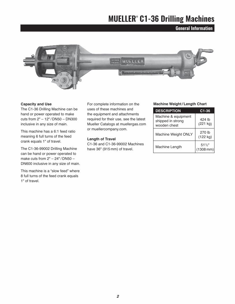
Capacity and UseThe C1-36 Drilling Machine can be hand or power operated to make cuts from 2" – 12" / DN50 – DN300 inclusive in any size of main.
This machine has a 6:1 feed ratio meaning 6 full turns of the feed crank equals 1" of travel.
The C1-36-99002 Drilling Machine can be hand or power operated to make cuts from 2" – 24" / DN50 – DN600 inclusive in any size of main.
This machine is a “slow feed” where 8 full turns of the feed crank equals 1" of travel.
Machine Weight / Length Chart
desCRIptIoN C1-36Machine & equipment
424 lbshipped in strong (221 kg)wooden chest
Machine Weight ONLy 270 lb
(122 kg)
Machine Length 511/2" (1308 mm)
For complete information on the uses of these machines and the equipment and attachments required for their use, see the latest Mueller Catalogs at muellergas.com or muellercompany.com.
Length of travelC1-36 and C1-36-99002 Machines have 36" (915 mm) of travel.
MUELLER® C1-36 Drilling MachinesMaintenance Instructions
2 3
6. Place gland in a vise or clamp so that packing will not “spring” out of gland when the two retaining pins (Part No. 47092) are removed.7. Remove retaining pins.8. Model 3 and prior: Remove concave follower, four packing rings, convex follower, and spring from the gland.9. Remove any burrs from the boring bar drive lugs. Lubricate the boring bar and inside of the new packing rings with a light film of oil or cutting grease.10. Remove cap screws from alternate tapped holes in gland.11. Replace boring bar wiper ring (Part No. 501158) and gland seal O-ring (Part No. 52162) if necessary. Place gland on boring bar being careful not to damage packing ring or the wiper ring.12. Slide gland into flange recess. Insert and tighten cap screws evenly and securely.13. Replace hub retaining bolt and nut.
Cutters SHARPEN CUTTERS AND PILOT DRILLS By TOUCHING THEM UP WITH AN OILSTONE BEFORE EACH CUT. If the cutters and/or pilot drills dull, return to Mueller Co. Contact Customer Service to arrange reconditioning.
oILING (Model 4, 5 & 6) for model 3 or earlier call Mueller Customer service.Keep the drive box and rear gear case of torque tube half full of a good grade oil with a Saybolt Universal Viscosity of 200 Sec., at 210°F. Change oil periodically. Drain old oil and replace with 4 pints in drive box and 1.6 pints in rear gear case of torque tube. Mueller Part No. 89347 gear oil is used and needs no thinning in cold weather.
packingBoring Bar Packing is the self-adjusting type. If packing leaks. Replace it as follows:1. Remove hub retaining bolt (Part No. 311866) and nut (Part No. 058849) from boring bar.2. Remove 4 cap screws (Part No. 055098) from the gland (Part No. 581974).3. Insert cap screws into the alternative tapped holes in gland and screw them in all the way. This should be done evenly, tightening each cap screw a little at a time. This will cause the gland to move forward evenly out of the gland recess until the gland seal O-ring (Part No. 52162) is exposed.4. Rotate crank handle (Part No. 88150) counter-clockwise and advance boring bar 6 or 8 inches. This will cause the gland to move forward into an exposed position.5. Remove gland from boring bar.
CAUtIoN: Keeping cutters and pilot drills sharp assures maximum efficiency in cutting operations. When cutters are dull they not only make cutting more difficult, but place an additional strain on the teeth which can cause tooth breakage. When not in use, keep cutters in the machine chest or other wooden container. (NOTE: Be careful not to drop cutter and damage cutter teeth.) If necessary to rest cutter on teeth, place upon wood rather than brick, concrete, or metal.
After UseClean dirt, etc., from machine and equipment. Give cutters, drills, and equipment a light coat of oil to protect them from rust.
storageWhen not in use, the machine and equipment furnished with each machine should be stored in the chest furnished with the machine.NOTE: If the machine is stored or transported in the vertical position. It is recommended that before use it be placed in a horizontal position for a short period of time (1/2 hour), to allow grease to drain back into the rear grease case.
Maintenance of Machines and Equipment
!
MUELLER® C1-36 Drilling MachinesOperating Instructions
4
b) 2½"– 3" / Dn65 – Dn80. Assemble both the pilot drill and the shell cutter to the cutter arbor. Remove retaining screw from the shank of the arbor. Insert the shank of the arbor into the socket in the boring bar. Align the bolt hole in the end of the boring bar with the tapped hole in the shank of the arbor and replace the retaining screw.
c) Sizes larger than 3" / Dn80. Assemble shell cutter and cutter hub. Insert the end of the pilot drill into the socket in the boring bar. Slide cutter hub and shell cutter over the end of the boring bar. Align the holes in the cutter hub, boring bar and pilot drill and attach to boring bar with hub retaining bolt and nut.
Apply a small amount of Mueller cutting grease to the lead cutting edges of the shell cutter and pilot drill. DO NOT use cutting grease when cutting AC or concrete pipe.6. The term “valve”, as used in these instructions, refers to whatever type of valving means that is being used between the machine and the main. This might be a tapping valve, standard gate valve or line stopper fitting gate valve. If valve is being used, open completely and measure, or check, the exact size of opening and size of cutter to make sure the entire opening is clear and unobstructed and the cutter will pass freely.7. Retract boring bar to its rearmost position by rotating feed crank clockwise.8. Place the machine (with adapter and drilling equipment assembled) in drilling position. For horizontal use, support the assembly by blocking up under the machine and valve.NOTE: Make certain machined recess on adapter and lip on adapter flange and machine flange are flush.
1. INSPECT CUTTER AND PILOT DRILL TO MAKE SURE THAT THEy ARE SHARP. IF CUTTER IS DULL IT SHOULD BE SHARPENED AS DESCRIBED IN MAINTENANCE INSTRUCTIONS.2. Bolt proper size adapter to front of machine, being sure machine-to-adapter gasket is in good condition and in place. (All gaskets should be replaced periodically.)NOTE: Make certain machined recess on adapter and lip on adapter flange and machine flange are flush.3. Release automatic feed by pulling out automatic feed knob or disengaging with Auto Feed Lever. (Directions are indicated on panel on rear of torque tube.)4. Advance boring bar by rotating feed crank counter-clockwise until hub retaining bolt in boring bar is exposed beyond face of adapter. (Directions are indicated on panel on rear cover of torque tube.) Remove hub retaining bolt.5. Attach proper drilling equipment to boring bar. Check detent type pilot drills before each operation to make sure the detents will move completely to the submerged position.a) 1½"– 2" / Dn40 – Dn50. Remove
the retaining screws from the shank of the drill. Insert the shank into the socket in the boring bar. Align the hole in the end of the boring bar with the tapped hole in the shank of the drill and replace the retaining screws. See instructions under “CAUtIoN” on page 5.
a) Place machine and adapter against valve, allowing cutter to extend into the end of the valve. Cutter must not interfere with operation of the valve. (When machine is used horizontally, the driving spindle should be at a right angle to the main.) Bolt adapter to outlet flange of the valve, making certain that the adapter gasket is in place.
9. Close valve and test between tap sleeve / line stopper ftting and valve for pressure tightness. 10. Set feed indicator to zero. Mark the point on feed indicator that the arrow will reach when cut will be completed. (See pages 7 – 10 for travel chart.)For Gas applications, see page 10 for calculating the number of turns to contact main. 11. Rotate feed crank counter-clockwise to advance boring bar until pilot drill contacts the main. One turn of the feed crank moves the boring bar 1/6" (4 mm) – 6 revolutions equal 1" (25 mm). For C1-36-99002 machine, 8 revolutions equal 1" (25 mm). Back up boring bar 1/4 turn of feed crank clockwise to release tension between pilot drill and main.12. Engage automatic feed by pushing in on automatic feed mechanism.13. Rotate feed crank clockwise until dive key engages. This can be felt when feed crank ceases to freely rotate.a) When using the C1-36 Machine
and Mueller air or Hydraulic Motors: Refer to Form 12237 for H-614 Air motor, Form 12480 for Hydraulic motor.If cutting becomes difficult and stalling occurs, follow one of the methods listed in instruction 20.
4
MUELLER® C1-36 Drilling MachinesOperating Instructions
5
17. Close valve securely.
18. Unbolt adapter from valve and remove adapter and drilling machine from valve as a unit.
19. Advance boring bar by rotating feed crank counter-clockwise and remove hub retaining bolt, (retaining screw from cutter arbor or retaining screws from shank of solid drill.) Remove cut-out section of pipe, shell cutter, cutter hub or cutter arbor and pilot drill as a unit.
20. If cutting operation becomes difficult, follow one of these methods:a) If cutter has difficulty in cutting,
becomes dull or should stall after the cut is started, withdraw the cutter, close valve, remove machine and sharpen or replace cutter. Reassemble and proceed in the regular manner.
b) If cut is further along, release automatic feed and feed machine by hand by holding back on the feed crank at the rear of the machine a little each half revolution.
NOTE: Automatic feed should be used whenever possible. Automatic feed also provides the correct tool feed.
14. Continue the cutting operation until the cutter stops cutting or until feed indicator reads the amount shown in the travel chart. (See pages 7–10 for travel chart).
For Gas applications, see page 10 for calculating the number of turns to contact main.15. Check completion of cut by releasing automatic feed and attempting to advance cutter by rotating feed crank. If it does not advance easily, the cut is not completed and automatic feed knob must be pushed in to engage automatic feed for further cutting.
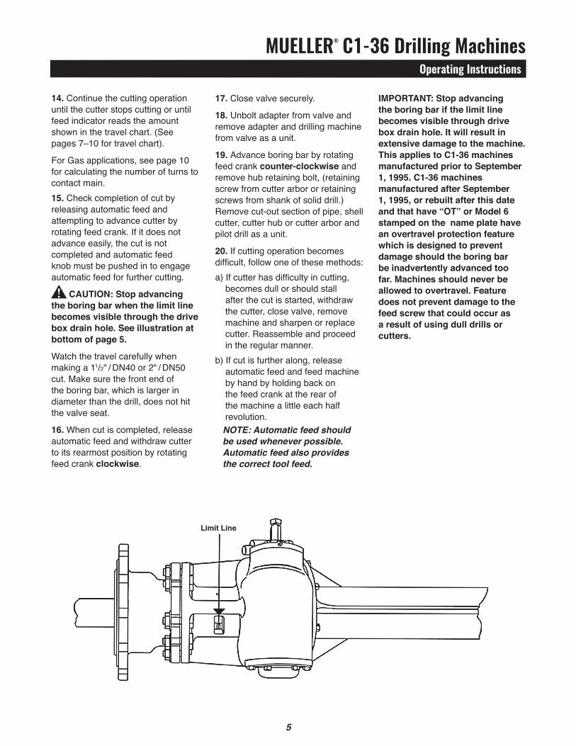
CAUtIoN: stop advancing the boring bar when the limit line becomes visible through the drive box drain hole. See illustration at bottom of page 5.
Watch the travel carefully when making a 11/2" / DN40 or 2" / DN50 cut. Make sure the front end of the boring bar, which is larger in diameter than the drill, does not hit the valve seat.
16. When cut is completed, release automatic feed and withdraw cutter to its rearmost position by rotating feed crank clockwise.
IMpoRtANt: stop advancing the boring bar if the limit line becomes visible through drive box drain hole. It will result in extensive damage to the machine. this applies to C1-36 machines manufactured prior to September 1, 1995. C1-36 machines manufactured after September 1, 1995, or rebuilt after this date and that have “ot” or Model 6 stamped on the name plate have an overtravel protection feature which is designed to prevent damage should the boring bar be inadvertently advanced too far. Machines should never be allowed to overtravel. Feature does not prevent damage to the feed screw that could occur as a result of using dull drills or cutters.
!
Limit Line
MUELLER® C1-36 Drilling MachinesOperating Instructions
6 7
3. Remove the cotter pin from the feed screw nut which is located in the center of the crank hub at the rear of the machine4. Back off the feed screw nut 3 revolutions only. DO NOT remove the feed screw nut.5. Rotate the feed crank in the clockwise direction until you feel the screw re-engage the feed nut.6. If the feed screw does not re-engage the feed nut: GENTLy tap on the feed screw nut with a soft mallet and repeat Step (5) above and this Step (6) until it does.7. Continue to turn the feed crank in the clockwise direction for 18 full revolutions. This will ensure full re-engagement between the feed screw and feed nut. Retighten the feed screw nut and replace the cotter pin.8. Resume normal operations.
Re-engaging overtravel FeatureTo re-engage the boring bar after it has overtraveled while making a cut on a pipe that is under pressure:1. Turn off the drive unit2. Disengage the automatic feed by pulling out on the automatic feed knob.3. Rotate the feed crank in the clockwise direction until the pickup of the feed nut is felt.4. Continue to turn the feed crank in the clockwise direction for 18 full revolutions. This will ensure full re-engagement between the feed screw and feed nut.5. Resume normal operation.
To re-engage the boring bar after it has overtraveled while making a cut on a pipe that is not under pressure, or if the feed screw will not engage the feed nut when the feed crank is turned in the clockwise direction:1. Turn off the drive unit.2. Disengage the automatic feed by pulling out on the automatic feed knob.
Overtravel Feature
MUELLER® C1-36 Drilling MachinesTravel Charts
7
OutsideDiameterof Cutter
11/2" 2" 21/2" 3"
11/2" 2" 21/2" 3" 31/2" 4"
11/2" 2" 21/2" 3" 31/2" 4" 51/2" 6"
11/2" 2" 21/2" 3" 31/2" 4" 51/2" 6" 71/2" 8"
11/2" 2" 21/2" 3" 31/2" 4" 51/2" 6" 71/2" 8" 91/2" 10"
ASA A 21.6.1953ASA A 21.8.1953AWWA C106-53AWWA C108-53
CLASS 150
11/4 11/2 2 23/8
11/4 11/2 13/4 2 17/8 27/8
11/4 13/8 13/4 17/8 11/2 2 23/4 43/8
11/4 13/8 15/8 13/4 11/2 17/8 21/4 33/8 43/8 51/8
11/4 13/8 15/8 13/4 11/4 13/4 2 3 35/8 37/8 41/2 57/8
ASA A 2.1953AWWA C102-53
CLASS 150
11/4 15/8 21/8 25/8
11/4 11/2 17/8 21/8 2 31/8*
11/4 11/2 13/4 17/8 11/2 21/8 3 45/8
11/4 11/2 13/4 13/4 11/2 17/8 21/2 33/8 41/2 53/8
13/8 11/2 13/4 17/8 11/2 17/8 21/2 31/8 33/4 41/8 43/4 65/8
AWWA 1908 Standard
CLASS B
13/8 15/8 21/8 25/8
13/8 15/8 17/8 21/8 2 3
13/8 11/2 13/4 17/8 13/4 21/4 3 43/8
13/8 11/2 13/4 17/8 11/2 2 21/2 33/8 45/8 55/8
13/8 11/2 13/4 1 7/8 11/2 17/8 21/2 31/8 37/8 41/8 43/4 63/4*
AWWA 1908 Standard
CLASS D
13/8 13/4 21/4 23/4*
13/8 15/8 2 21/4 2 31/8*
13/8 15/8 17/8 2 13/4 25/16
3 47/8*
13/8 15/8 17/8 2 11/2 21/8 21/2 31/2 45/8 53/4
11/2 15/8 17/8 2 11/2 2 21/2 31/4 37/8 41/4 43/4 67/8
ASA A 21.7.1953
ASA A 21.9.1953
CLASS 10
11/4 11/2 13/4 2 17/8 27/8
11/4 13/8 13/4 17/8 11/2 2 21/2 43/8
11/4 13/8 15/8 13/4 11/2 17/8 21/2 31/4 43/8 51/8
11/4 13/8 15/8 13/4 11/2 13/4 2 3 35/8 37/8 43/4 57/8
AGAOld
Standard
11/4 11/2 17/8 21/8 2 31/8*
11/4 11/2 13/4 17/8 11/2 21/8 3 45/8
11/4 11/2 13/4 13/4 11/2 17/8 21/2 33/8 41/2 51/4
11/4 11/2 13/4 13/4 11/2 17/8 21/2 3 33/4 4 43/4 61/4
Schedule
40
11/8 11/2 17/8 21/2
11/8 13/8 13/4 2 13/4 3
11/8 13/8 15/8 13/4 11/2 2 21/2 43/8
11/8 13/8 15/8 15/8 11/2 13/4 21/2 31/4 41/2 55/8*
11/8 13/8 15/8 15/8 11/2 13/4 21/2 27/8 35/8 37/8 43/4 61/2
Schedule
80
11/4 15/8 21/8 21/2*
11/4 11/2 17/8 21/8 2 27/8*
11/4 11/2 13/4 17/8 21/2 21/8 31/4 45/8*
13/8 11/2 13/4 17/8 11/2 2 21/2 31/2 51/8 55/8*
13/8 15/8 17/8 17/8 11/2 2 21/2 31/4 4 41/4 43/4 61/2*
NominalSize
of Pipeto be Cut
3"
4"
6"
8"
10"
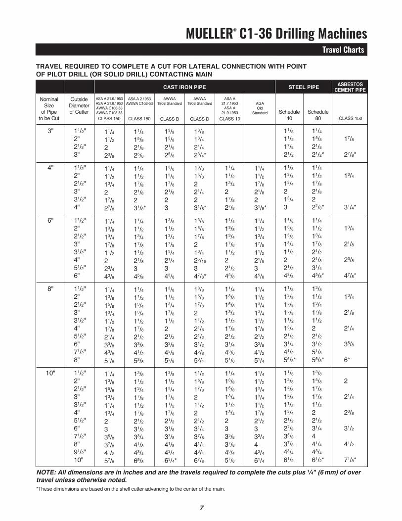
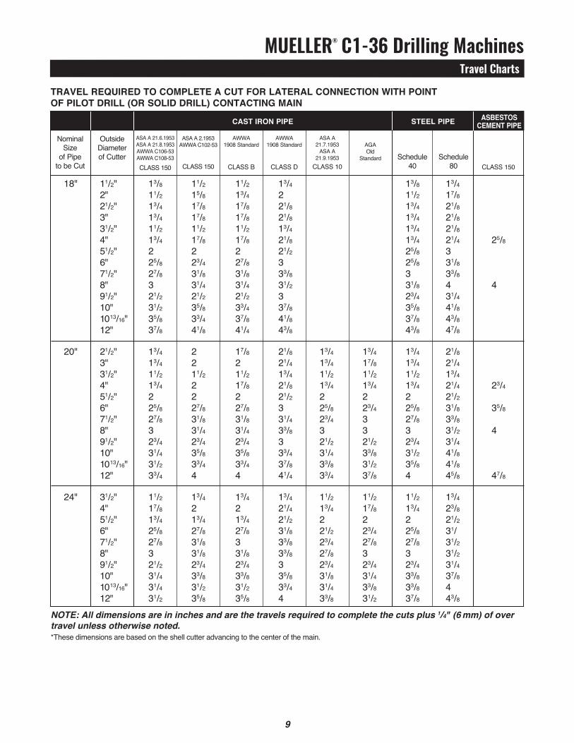
NOTE: All dimensions are in inches and are the travels required to complete the cuts plus 1/4" (6 mm) of over travel unless otherwise noted.*These dimensions are based on the shell cutter advancing to the center of the main.
CLASS 150
17/8 27/8*
13/4 31/4*
13/4 21/8 23/8 47/8*
13/4 21/8 21/4 35/8 6*
2 21/4 23/8 31/2 41/2 71/8*
OutsideDiameterof Cutter
ASA A 21.6.1953ASA A 21.8.1953AWWA C106-53AWWA C108-53CLASS 150
ASA A 2.1953AWWA C102-53
CLASS 150
AWWA 1908 Standard
CLASS B
AWWA 1908 Standard
CLASS D
ASA A 21.7.1953
ASA A 21.9.1953
CLASS 10
AGAOld
Standard
Schedule
40
Schedule
80
NominalSize
of Pipeto be Cut
tRAVeL ReQUIRed to CoMpLete A CUt FoR LAteRAL CoNNeCtIoN WItH poINt oF pILot dRILL (oR soLId dRILL) CoNtACtING MAIN
CAst IRoN pIpe steeL pIpe AsBestosCeMeNt pIpe
MUELLER® C1-36 Drilling MachinesTravel Charts
8
11/2" 2" 21/2" 3" 31/2" 4" 51/2" 6" 71/2" 8" 91/2" 10" 1013/16" 12"
11/2" 2" 21/2" 3" 31/2" 4" 51/2" 6" 71/2" 8" 91/2" 10" 1013/16" 12"
11/2" 2" 21/2" 3" 31/2" 4" 51/2" 6" 71/2" 8" 91/2" 10" 1013/16" 12"
11/4 13/8 25/8 13/4 11/2 13/4 2 27/8 33/8 31/2 31/2 41/2 5 65/8
11/4 11/2 15/8 15/8 11/2 13/4 2 23/4 31/8 31/4 31/2 37/8 41/4 47/8
13/8 11/2 13/4 13/4 11/2 13/4 2 25/8 3 31/8 3 35/8 37/8 41/4
13/8 11/2 13/4 17/8 11/2 17/8 2 3 31/2 35/8 33/4 45/8 51/4 71/4
13/8 15/8 13/4 17/8 11/2 17/8 2 27/8 31/4 33/8 31/2 41/8 43/8 5
11/2 15/8 17/8 17/8 11/2 17/8 2 23/4 31/8 31/4 3 33/4 4 41/2
13/8 15/8 13/4 17/8 11/2 17/8 21/2 3 31/2 35/8 33/4 43/4 53/8 71/2*
11/2 15/8 17/8 17/8 11/2 17/8 2 27/8 31/4 31/2 31/2 41/4 41/2 51/4
11/2 15/8 17/8 17/8 11/2 17/8 2 27/8 31/4 33/8 31/2 37/8 41/8 45/8
11/2 13/4 2 2 11/2 2 21/2 31/8 35/8 33/4 33/4 47/8 51/2 75/8*
15/8 13/4 2 2 13/4 2 21/2 3 31/2 35/8 31/2 43/8 43/4 53/8
2 17/8 2 21/8 11/2 21/8 21/8 3 33/8 31/2 31/2 41/8 41/4 43/4
11/4 11/2 15/8 13/4 11/2 13/4 21/2 27/8 33/8 31/2 33/4 41/2 5 65/8
11/4 11/2 15/8 13/4 11/2 15/8 2 25/8 3 31/8 3 35/8 37/8 41/4
13/8 11/2 13/4 13/4 11/2 13/4 21/2 27/8 33/8 35/8 33/4 45/8 51/8 65/8
13/8 15/8 13/4 11/2 17/8 13/4 2 23/4 31/8 31/4 3 33/4 4 41/2
11/4 13/8 15/8 15/8 11/2 15/8 2 23/4 31/4 31/2 33/4 51/8 51/8 73/8*
11/4 13/8 15/8 15/8 11/2 15/8 2 23/4 31/8 33/8 31/2 41/8 41/4 55/8
11/4 11/2 15/8 11/2 13/4 13/4 2 25/8 3 31/4 3 37/8 41/8 43/4
11/2 15/8 17/8 2 11/2 2 21/2 31/8 35/8 37/8 33/4 51/8 57/8 73/8*
11/2 13/4 17/8 2 11/2 2 21/2 31/8 31/2 33/4 33/4 45/8 51/8 61/2
15/8 13/4 2 11/2 21/8 2 21/2 3 31/2 35/8 31/2 41/4 45/8 53/8
21/8
21/4
31/2
41/8
51/4
8*
31/2
4
43/4 57/8
31/2
4
41/2 51/4
12"
14"
16"
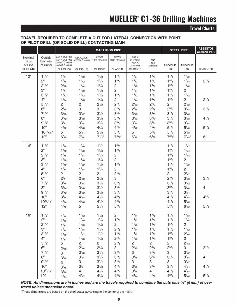
NOTE: All dimensions are in inches and are the travels required to complete the cuts plus 1/4" (6 mm) of over travel unless otherwise noted.*These dimensions are based on the shell cutter advancing to the center of the main.
OutsideDiameterof Cutter
ASA A 21.6.1953ASA A 21.8.1953AWWA C106-53AWWA C108-53CLASS 150
ASA A 2.1953AWWA C102-53
CLASS 150
AWWA 1908 Standard
CLASS B
AWWA 1908 Standard
CLASS D
ASA A 21.7.1953
ASA A 21.9.1953
CLASS 10
AGAOld
Standard
Schedule 40
Schedule
80
CLASS 150
NominalSize
of Pipeto be Cut
tRAVeL ReQUIRed to CoMpLete A CUt FoR LAteRAL CoNNeCtIoN WItH poINt oF pILot dRILL (oR soLId dRILL) CoNtACtING MAIN
CAst IRoN pIpe steeL pIpe AsBestosCeMeNt pIpe
MUELLER® C1-36 Drilling MachinesTravel Charts
8 9
NOTE: All dimensions are in inches and are the travels required to complete the cuts plus 1/4" (6 mm) of over travel unless otherwise noted.*These dimensions are based on the shell cutter advancing to the center of the main.
11/2" 2" 21/2" 3" 31/2" 4" 51/2" 6" 71/2" 8" 91/2" 10" 1013/16" 12"
21/2" 3" 31/2" 4" 51/2" 6" 71/2" 8" 91/2" 10" 1013/16" 12"
31/2" 4" 51/2" 6" 71/2" 8" 91/2" 10" 1013/16" 12"
13/8 11/2 13/4 13/4 11/2 13/4 2 25/8 27/8 3 21/2 31/2 35/8 37/8
13/4 13/4 11/2 13/4 2 25/8 27/8 3 23/4 31/4 31/2 33/4
11/2 17/8 13/4 25/8 27/8 3 21/2 31/4 31/4 31/2
11/2 15/8 17/8 17/8 11/2 17/8 2 23/4 31/8 31/4 21/2 35/8 33/4 41/8
2 2 11/2 2 2 27/8 31/8 31/4 23/4 35/8 33/4 4
13/4 2 13/4 27/8 31/8 31/8 23/4 33/8 31/2 35/8
11/2 13/4 17/8 17/8 11/2 17/8 2 27/8 31/8 31/4 21/2 33/4 37/8 41/4
17/8 2 11/2 17/8 2 27/8 31/8 31/4 23/4 35/8 33/4 4
13/4 2 13/4 27/8 3 31/8 23/4 33/8 31/2 35/8
13/4 2 21/8 21/8 13/4 21/8 21/2 3 33/8 31/2 3 37/8 41/8 43/8
21/8 21/4 13/4 21/8 21/2 3 31/4 33/8 3 33/4 37/8 41/4
13/4 21/4 21/2 31/8 33/8 33/8 3 35/8 33/4 4
13/4 13/4 11/2 13/4 2 25/8 23/4 3 21/2 31/4 33/8 33/4
11/2 13/4 2 21/2 23/4 27/8 23/4 31/8 31/4 33/8
13/4 17/8 11/2 13/4 2 23/4 3 3 21/2 33/8 31/2 37/8
11/2 17/8 2 23/4 27/8 3 23/4 31/4 33/8 31/2
13/8 11/2 13/4 13/4 13/4 13/4 25/8 25/8 3 31/8 23/4 35/8 37/8 43/8
13/4 13/4 11/2 13/4 2 25/8 27/8 3 23/4 31/2 35/8 4
11/2 13/4 2 25/8 27/8 3 23/4 33/8 33/8 37/8
13/4 17/8 21/8 21/8 21/8 21/4 3 31/8 33/8 4 31/4 41/8 43/8 47/8
21/8 21/4 13/4 21/4 21/2 31/8 33/8 31/2 31/4 41/8 41/8 45/8
13/4 23/8 21/2 31/ 31/2 31/2 31/4 37/8 4 43/8
25/8
4
23/4
35/8
4
47/8
18"
20"
24"
CLASS 150
OutsideDiameterof Cutter
ASA A 21.6.1953ASA A 21.8.1953AWWA C106-53AWWA C108-53CLASS 150
ASA A 2.1953AWWA C102-53
CLASS 150
AWWA 1908 Standard
CLASS B
AWWA 1908 Standard
CLASS D
ASA A 21.7.1953
ASA A 21.9.1953
CLASS 10
AGAOld
Standard
Schedule
40
Schedule
80
NominalSize
of Pipeto be Cut
tRAVeL ReQUIRed to CoMpLete A CUt FoR LAteRAL CoNNeCtIoN WItH poINt oF pILot dRILL (oR soLId dRILL) CoNtACtING MAIN
CAst IRoN pIpe steeL pIpe AsBestosCeMeNt pIpe
MUELLER® C1-36 Drilling MachinesTravel Charts / Calculating C1-36 Turns
10 11
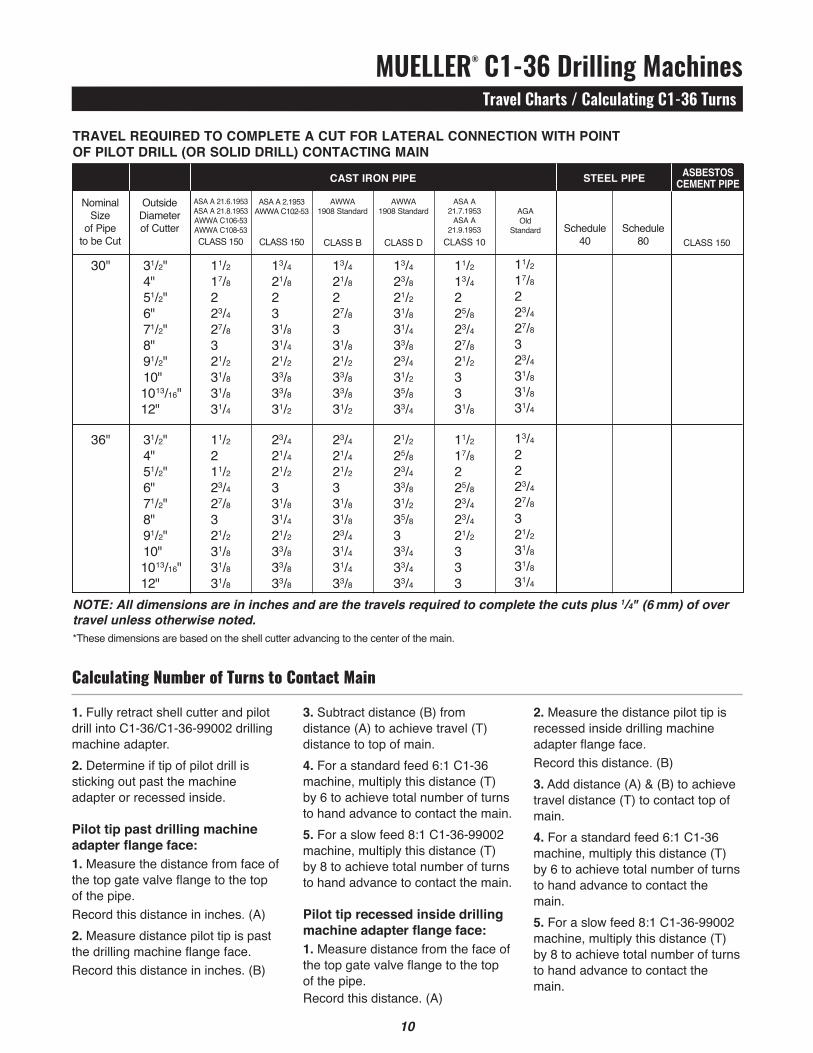
NOTE: All dimensions are in inches and are the travels required to complete the cuts plus 1/4" (6 mm) of over travel unless otherwise noted.*These dimensions are based on the shell cutter advancing to the center of the main.
31/2" 4" 51/2" 6" 71/2" 8" 91/2" 10" 1013/16" 12"
31/2" 4" 51/2" 6" 71/2" 8" 91/2" 10" 1013/16" 12"
11/2 17/8 2 23/4 27/8 3 21/2 31/8 31/8 31/4
11/2 2 11/2 23/4 27/8 3 21/2 31/8 31/8 31/8
13/4 21/8 2 3 31/8 31/4 21/2 33/8 33/8 31/2
23/4 21/4 21/2 3 31/8 31/4 21/2 33/8 33/8 33/8
13/4 21/8 2 27/8 3 31/8 21/2 33/8 33/8 31/2
23/4 21/4 21/2 3 31/8 31/8 23/4 31/4 31/4 33/8
13/4 23/8 21/2 31/8 31/4 33/8 23/4 31/2 35/8 33/4
21/2 25/8 23/4 33/8 31/2 35/8 3 33/4 33/4 33/4
11/2 13/4 2 25/8 23/4 27/8 21/2 3 3 31/8
11/2 17/8 2 25/8 23/4 23/4 21/2 3 3 3
11/2 17/8 2 23/4 27/8 3 23/4 31/8 31/8 31/4
13/4 2 2 23/4 27/8 3 21/2 31/8 31/8 31/4
30"
36"
CLASS 150
OutsideDiameterof Cutter
ASA A 21.6.1953ASA A 21.8.1953AWWA C106-53AWWA C108-53CLASS 150
ASA A 2.1953AWWA C102-53
CLASS 150
AWWA 1908 Standard
CLASS B
AWWA 1908 Standard
CLASS D
ASA A 21.7.1953
ASA A 21.9.1953
CLASS 10
AGAOld
Standard
Schedule 40
Schedule
80
NominalSize
of Pipeto be Cut
tRAVeL ReQUIRed to CoMpLete A CUt FoR LAteRAL CoNNeCtIoN WItH poINt oF pILot dRILL (oR soLId dRILL) CoNtACtING MAIN
CAst IRoN pIpe steeL pIpe AsBestosCeMeNt pIpe
3. Subtract distance (B) from distance (A) to achieve travel (T) distance to top of main.4. For a standard feed 6:1 C1-36 machine, multiply this distance (T) by 6 to achieve total number of turns to hand advance to contact the main.5. For a slow feed 8:1 C1-36-99002 machine, multiply this distance (T) by 8 to achieve total number of turns to hand advance to contact the main.
pilot tip recessed inside drilling machine adapter flange face:1. Measure distance from the face of the top gate valve flange to the top of the pipe.Record this distance. (A)
1. Fully retract shell cutter and pilot drill into C1-36/C1-36-99002 drilling machine adapter.2. Determine if tip of pilot drill is sticking out past the machine adapter or recessed inside.
pilot tip past drilling machine adapter flange face:1. Measure the distance from face of the top gate valve flange to the top of the pipe.Record this distance in inches. (A)2. Measure distance pilot tip is past the drilling machine flange face. Record this distance in inches. (B)
2. Measure the distance pilot tip is recessed inside drilling machine adapter flange face. Record this distance. (B)3. Add distance (A) & (B) to achieve travel distance (T) to contact top of main.4. For a standard feed 6:1 C1-36 machine, multiply this distance (T) by 6 to achieve total number of turns to hand advance to contact the main.5. For a slow feed 8:1 C1-36-99002 machine, multiply this distance (T) by 8 to achieve total number of turns to hand advance to contact the main.
Calculating Number of Turns to Contact Main
MUELLER® C1-36 Drilling MachinesInstallation Instructions
11
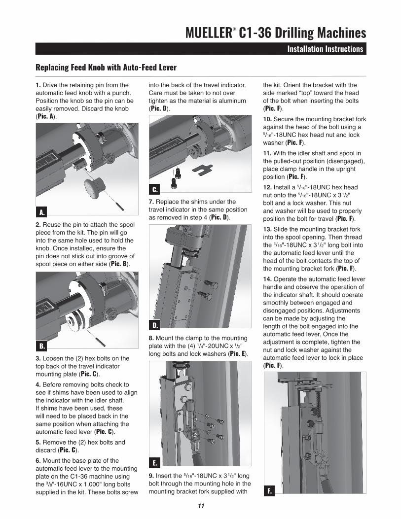
into the back of the travel indicator. Care must be taken to not over tighten as the material is aluminum (Pic. D).
7. Replace the shims under the travel indicator in the same position as removed in step 4 (Pic. D).
8. Mount the clamp to the mounting plate with the (4) 1/4"-20UNC x 1/2" long bolts and lock washers (Pic. E).
9. Insert the 5/16"-18UNC x 31/2" long bolt through the mounting hole in the mounting bracket fork supplied with
1. Drive the retaining pin from the automatic feed knob with a punch. Position the knob so the pin can be easily removed. Discard the knob (Pic. A).
2. Reuse the pin to attach the spool piece from the kit. The pin will go into the same hole used to hold the knob. Once installed, ensure the pin does not stick out into groove of spool piece on either side (Pic. B).
3. Loosen the (2) hex bolts on the top back of the travel indicator mounting plate (Pic. C).4. Before removing bolts check to see if shims have been used to align the indicator with the idler shaft. If shims have been used, these will need to be placed back in the same position when attaching the automatic feed lever (Pic. C).5. Remove the (2) hex bolts and discard (Pic. C).6. Mount the base plate of the automatic feed lever to the mounting plate on the C1-36 machine using the 3/8"-16UNC x 1.000" long bolts supplied in the kit. These bolts screw
Replacing Feed Knob with Auto-Feed Lever
A.
C.
E.
B.
D.
the kit. Orient the bracket with the side marked “top” toward the head of the bolt when inserting the bolts (Pic. F).10. Secure the mounting bracket fork against the head of the bolt using a 5/16"-18UNC hex head nut and lock washer (Pic. F).11. With the idler shaft and spool in the pulled-out position (disengaged), place clamp handle in the upright position (Pic. F).12. Install a 5/16"-18UNC hex head nut onto the 5/16"-18UNC x 31/2" bolt and a lock washer. This nut and washer will be used to properly position the bolt for travel (Pic. F).13. Slide the mounting bracket fork into the spool opening. Then thread the 5/16"-18UNC x 31/2" long bolt into the automatic feed lever until the head of the bolt contacts the top of the mounting bracket fork (Pic. F).14. Operate the automatic feed lever handle and observe the operation of the indicator shaft. It should operate smoothly between engaged and disengaged positions. Adjustments can be made by adjusting the length of the bolt engaged into the automatic feed lever. Once the adjustment is complete, tighten the nut and lock washer against the automatic feed lever to lock in place (Pic. F).
F.

Gas (North America)[email protected]
Form 8513 – Rev 08/18
Copyright © 2016 Mueller Co., LLC. All Rights Reserved.The trademarks, logos and service marks displayed in this document herein are the property of Mueller Co., LLC, its affiliates or other third parties. Products marked with a section symbol ( § ) are subject to patents or patent applications. For details, visit www.mwppat.com. These products are intended for use in potable water applications. Please contact your Mueller Sales or Customer Service Representative concerning any other application(s).
Reliable ConnectionsTM
International1.423.490.9555www.mueller-international.cominternational@muellercompany.com
Water (North America)[email protected]