ms05 applied seabed geomorphology in cable route … · abstract: geomorphological mapping is a...
TRANSCRIPT
Marine Services and Operations
Copyright © SubOptic2016 Page 1 of 5
APPLIED SEABED GEOMORPHOLOGY IN CABLE ROUTE
PLANNING, SURVEYING AND ENGINEERING
Elias Tahchi (EGS), Bell Chan (EGS), Aaron Micallef (University of Malta, Malta) and Joyce Chan (EGS) Email: [email protected] EGS (Asia) Ltd., 5/F, Zung Fu Industrial Building, 1067 King's Road, Quarry Bay, Hong Kong, China. Abstract: Geomorphological mapping is a fundamental requirement in cable route planning, surveying and engineering. It comprises several constituents that require sophisticated equipment to collect and build. Efforts are being made by industrial and academic institutions to provide harmonized standards to render geomorphological maps to be scientifically holistic. Compilation of geomorphological maps in most cases is assigned to laymen and the maps are designated to be read by laymen. Thus, a new approach has been developed in EGS to maintain geomorphological information precision and easy information transfer for cable route surveying and engineering. Applied geomorphology will allow a cost effective design of a survivable cable network, optimizing the shapes of the submarine cables taking into consideration of the seabed topology. 1. GEOMORPHOLOGY AND ITS
CONSTITUENTS
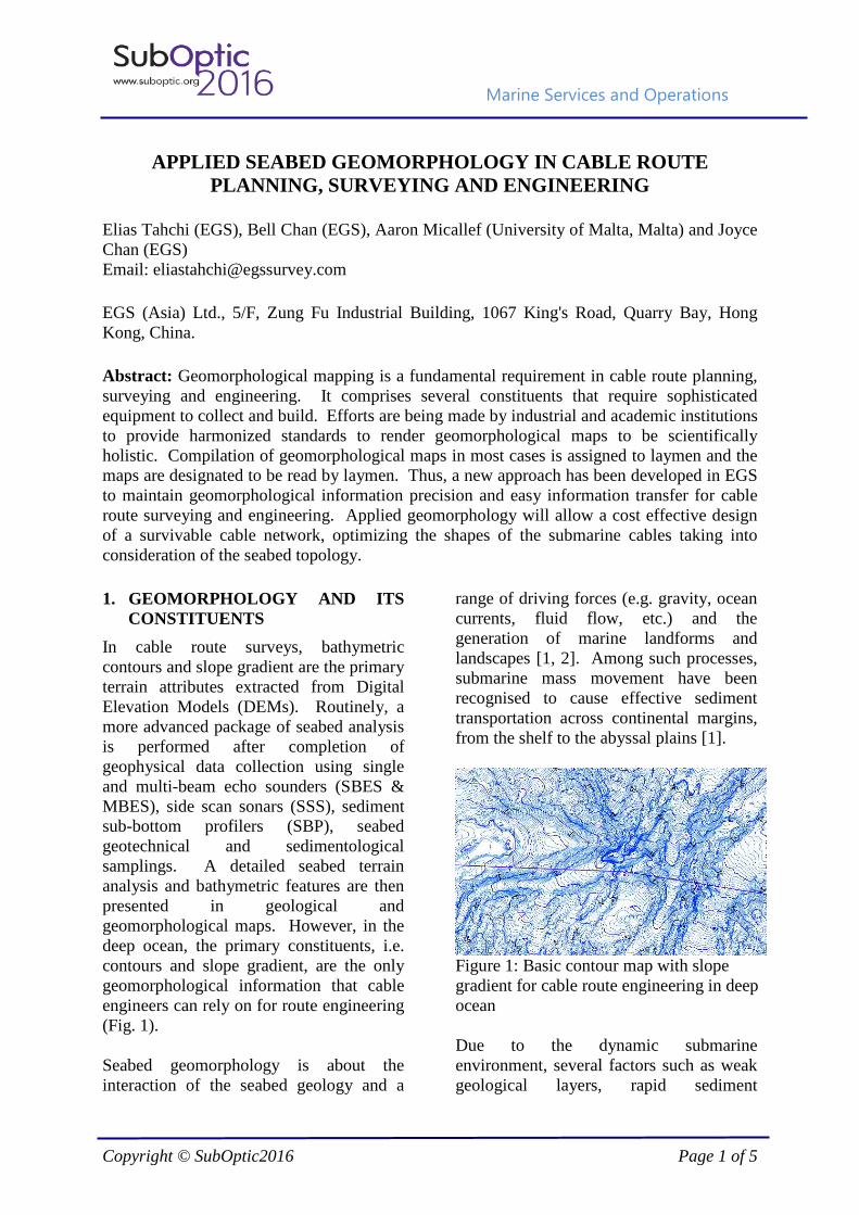
In cable route surveys, bathymetric contours and slope gradient are the primary terrain attributes extracted from Digital Elevation Models (DEMs). Routinely, a more advanced package of seabed analysis is performed after completion of geophysical data collection using single and multi-beam echo sounders (SBES & MBES), side scan sonars (SSS), sediment sub-bottom profilers (SBP), seabed geotechnical and sedimentological samplings. A detailed seabed terrain analysis and bathymetric features are then presented in geological and geomorphological maps. However, in the deep ocean, the primary constituents, i.e. contours and slope gradient, are the only geomorphological information that cable engineers can rely on for route engineering (Fig. 1). Seabed geomorphology is about the interaction of the seabed geology and a
range of driving forces (e.g. gravity, ocean currents, fluid flow, etc.) and the generation of marine landforms and landscapes [1, 2]. Among such processes, submarine mass movement have been recognised to cause effective sediment transportation across continental margins, from the shelf to the abyssal plains [1].
Figure 1: Basic contour map with slope gradient for cable route engineering in deep ocean Due to the dynamic submarine environment, several factors such as weak geological layers, rapid sediment
Marine Services and Operations
Copyright © SubOptic2016 Page 2 of 5
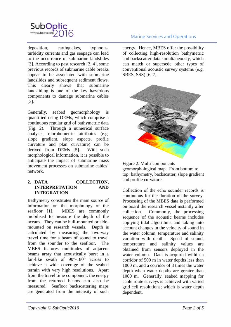
deposition, earthquakes, typhoons, turbidity currents and gas seepage can lead to the occurrence of submarine landslides [3]. According to past research [3, 4], some previous records of submarine cable breaks appear to be associated with submarine landslides and subsequent sediment flows. This clearly shows that submarine landsliding is one of the key hazardous components to damage submarine cables [3]. Generally, seabed geomorphology is quantified using DEMs, which comprise a continuous regular grid of bathymetric data (Fig. 2). Through a numerical surface analysis, morphometric attributes (e.g. slope gradient, slope aspects, profile curvature and plan curvature) can be derived from DEMs [5]. With such morphological information, it is possible to anticipate the impact of submarine mass movement processes on submarine cables’ network. 2. DATA COLLECTION,
INTERPRETATION AND INTEGRATION
Bathymetry constitutes the main source of information on the morphology of the seafloor [1]. MBES are commonly mobilised to measure the depth of the oceans. They can be hull-mounted or side-mounted on research vessels. Depth is calculated by measuring the two-way travel time for a beam of sound to travel from the sounder to the seafloor. The MBES features multitudes of adjacent beams array that acoustically burst in a fan-like swath of 90°-180° across to achieve a wide coverage of the seabed terrain with very high resolutions. Apart from the travel time component, the energy from the returned beams can also be measured. Seafloor backscattering maps are generated from the intensity of such
energy. Hence, MBES offer the possibility of collecting high-resolution bathymetric and backscatter data simultaneously, which can match or supersede other types of conventional acoustic survey systems (e.g. SBES, SSS) [6, 7].
Figure 2: Multi-components geomorphological map. From bottom to top: bathymetry, backscatter, slope gradient and profile curvature. Collection of the echo sounder records is continuous for the duration of the survey. Processing of the MBES data is performed on board the research vessel instantly after collection. Commonly, the processing sequence of the acoustic beams includes applying tidal algorithms and taking into account changes in the velocity of sound in the water column, temperature and salinity variation with depth. Speed of sound, temperature and salinity values are obtained from sensors deployed in the water column. Data is acquired within a corridor of 500 m in water depths less than 1000 m, and a corridor of 3 times the water depth when water depths are greater than 1000 m. Generally, seabed mapping for cable route surveys is achieved with varied grid cell resolutions; which is water depth dependent.
Marine Services and Operations
Copyright © SubOptic2016 Page 3 of 5
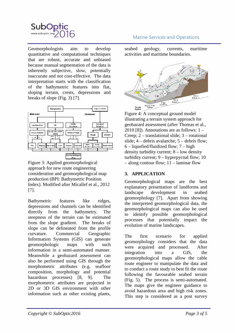
Geomorphologists aim to develop quantitative and computational techniques that are robust, accurate and unbiased because manual segmentation of the data is inherently subjective, slow, potentially inaccurate and not cost-effective. The data interpretation starts with the classification of the bathymetric features into flat, sloping terrain, crests, depressions and breaks of slope (Fig. 3) [7].
Figure 3: Applied geomorphological approach for new route engineering consideration and geomorphological map production (BPI: Bathymetric Position Index). Modified after Micallef et al., 2012 [7]. Bathymetric features like ridges, depressions and channels can be identified directly from the bathymetry. The steepness of the terrain can be estimated from the slope gradient. The breaks of slope can be delineated from the profile curvature. Commercial Geographic Information Systems (GIS) can generate geomorphologic maps with such information in a semi-automated manner. Meanwhile a geohazard assessment can also be performed using GIS through the morphometric attributes (e.g. seafloor composition, morphology and potential hazardous processes) [8, 9]. The morphometric attributes are projected in 2D or 3D GIS environment with other information such as other existing plants,
seabed geology, currents, maritime activities and maritime boundaries.
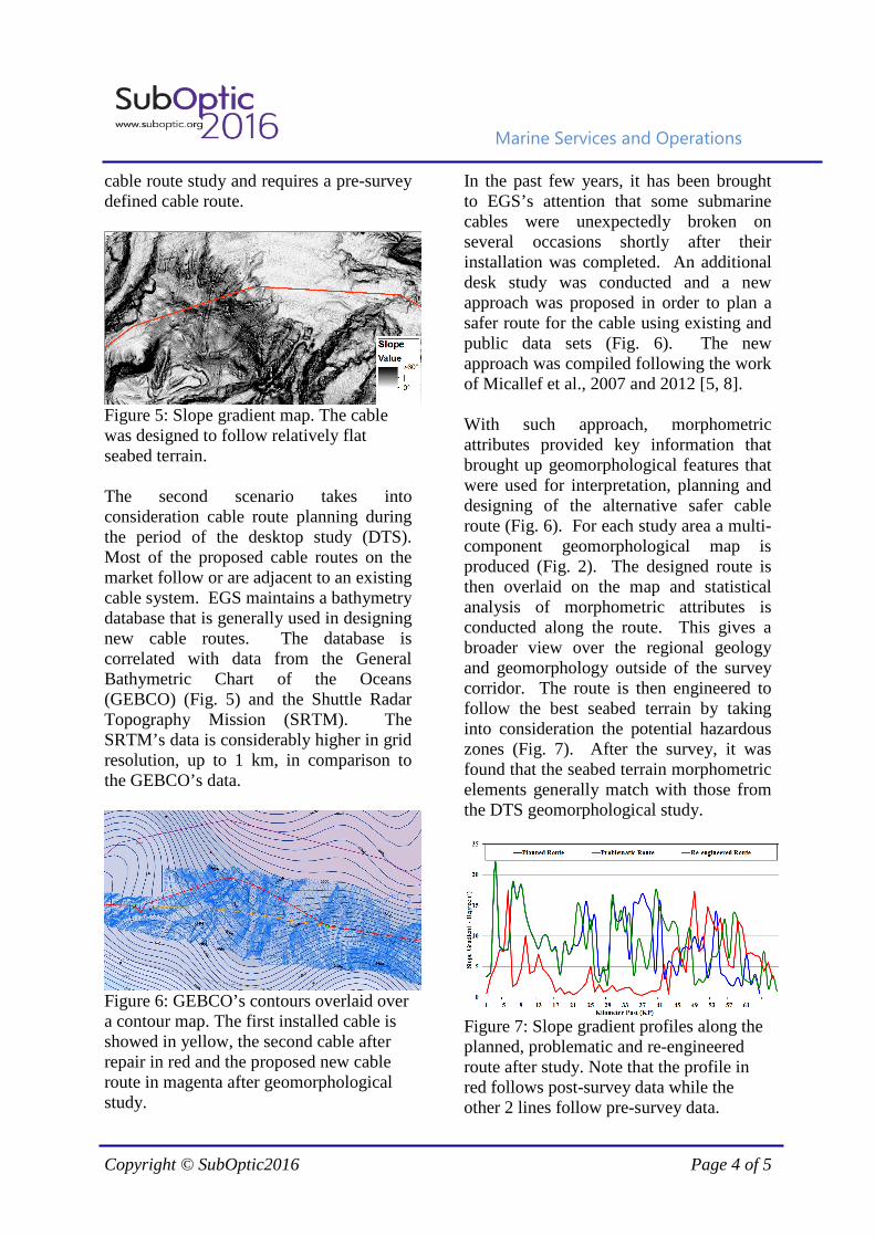
Figure 4: A conceptual ground model illustrating a terrain system approach for geohazard assessment (after Thomas et al., 2010 [8]). Annotations are as follows: 1 – Creep; 2 – translational slide; 3 – rotational slide; 4 – debris avalanche; 5 – debris flow; 6 – liquefied/fluidized flow; 7 – high density turbidity current; 8 – low density turbidity current; 9 – hyperpycnal flow; 10 – along contour flow; 11 – laminar flow 3. APPLICATION
Geomorphological maps are the best explanatory presentation of landforms and landscape development in seabed geomorphology [7]. Apart from showing the interpreted geomorphological data, the geomorphological maps can also be used to identify possible geomorphological processes that potentially impact the evolution of marine landscapes. The first scenario for applied geomorphology considers that the data were acquired and processed. After integration into a GIS, the geomorphological maps allow the cable route engineer to manipulate the data and to conduct a route study to best fit the route following the favourable seabed terrain (Fig. 5). The process is semi-automated. The maps give the engineer guidance to avoid hazardous area and high risk zones. This step is considered as a post survey
Marine Services and Operations
Copyright © SubOptic2016 Page 4 of 5
cable route study and requires a pre-survey defined cable route.
Figure 5: Slope gradient map. The cable was designed to follow relatively flat seabed terrain. The second scenario takes into consideration cable route planning during the period of the desktop study (DTS). Most of the proposed cable routes on the market follow or are adjacent to an existing cable system. EGS maintains a bathymetry database that is generally used in designing new cable routes. The database is correlated with data from the General Bathymetric Chart of the Oceans (GEBCO) (Fig. 5) and the Shuttle Radar Topography Mission (SRTM). The SRTM’s data is considerably higher in grid resolution, up to 1 km, in comparison to the GEBCO’s data.
Figure 6: GEBCO’s contours overlaid over a contour map. The first installed cable is showed in yellow, the second cable after repair in red and the proposed new cable route in magenta after geomorphological study.
In the past few years, it has been brought to EGS’s attention that some submarine cables were unexpectedly broken on several occasions shortly after their installation was completed. An additional desk study was conducted and a new approach was proposed in order to plan a safer route for the cable using existing and public data sets (Fig. 6). The new approach was compiled following the work of Micallef et al., 2007 and 2012 [5, 8]. With such approach, morphometric attributes provided key information that brought up geomorphological features that were used for interpretation, planning and designing of the alternative safer cable route (Fig. 6). For each study area a multi-component geomorphological map is produced (Fig. 2). The designed route is then overlaid on the map and statistical analysis of morphometric attributes is conducted along the route. This gives a broader view over the regional geology and geomorphology outside of the survey corridor. The route is then engineered to follow the best seabed terrain by taking into consideration the potential hazardous zones (Fig. 7). After the survey, it was found that the seabed terrain morphometric elements generally match with those from the DTS geomorphological study.
Figure 7: Slope gradient profiles along the planned, problematic and re-engineered route after study. Note that the profile in red follows post-survey data while the other 2 lines follow pre-survey data.
Marine Services and Operations
Copyright © SubOptic2016 Page 5 of 5
4. CONLUSION
The approach of bathymetric parameterisation allows a better understanding of the seafloor morpho-bathymetric settings where a broader view over the regional geo-hazards is demonstrated. Pre and post-survey geomorphological studies underscore a better control of cable routes to avoid hazardous areas. Applied geomorphology is a useful tool for the cable route engineer. This new approach tends to standardise the various components extracted from the seafloor’s DEMs in order to be efficiently utilised in cable route planning and engineering. Additional parameters and approaches are being currently studied at the City University of Hong Kong to optimise survivability of wide-area submarine telecommunication networks in hazardous seabed terrain [10]. 5. REFERENCES
[1] A. Micallef, 2011, Marine Geomorphology: Geomorphological Mapping and the Study of Submarine Landslides , Chapter 13, Developments in Earth Surface Process, Volume 15, p377-395, Elsevier B.V. [2] E. Tahchi, R. Urgeles, C. Hübscher and J. Benkhelil, 2010, Mass Wating at the Easternmost Cyprus Arc, Off Syria, Eastern Mediterranean, D.C. Mosher et al. (eds.), Submarine Mass Movement and Their Consequences, Advances in Natural and Technological Hazards Research, Vol 28, p323-334, Springer Science B.V. [3] L. Carter, R. Gavey, P.J. Talling, and J.T. Liu, 2014, Insights into submarine geohazards from breaks in subsea telecommunication cables. Oceanography 27(2):58–67. [4] J. Local and H. J. Lee, Submarine landslides: advances and challenges, 2002, Can. Geotech. J. 39:193-212.
[5] A. Micallef, C. Berndt, D.G. Masson, D.A. Stow, 2007, A technique for the morphological characterization of submarine landscapes as exemplified by debris flows of the Storegga Slide, Journal of Geophysical Research, V112, F02001. [6] T.P. Le Bas and V.A.I. Huvenne, 2009, Acquisition and processing of backscatter data for habitat mapping: comparison of multibeam and sidescan systems. Applied Acoustics 70, 1248-1257 [7] A. Micallef, T.P. Le Bas, V.A.I. Huvenne, P. Blondel, V. Hühnerbach and A. Deidun, 2012, A multi-method approach for benthic habitat mapping of shallow coastal areas with high-resolution multibeam data, Continental Shelf Research 39-40, p14-26. [8] S. Thomas, J. Hooper and M. Clare, 2010, Constraining Geohazards to the Past: Impact Assessment of Submarine Mass Movements on Seabed Developments. D.C. Mosher et al. (eds.), Submarine Mass Movement and Their Consequences, Advances in Natural and Technological Hazards Research, Vol 28, p323-334, Springer Science B.V. [9] L. Carter, 2014, Guide to Natural Hazards, International Cable Protection Committee (ICPC). [10] M. Zukerman, S.K. Au, F. Cucker, J. Manton, B. Mukherjee, G. Wang, Y. Wang, J. Jang and X. Yuan, 2015, Cost Effective and Survivable Wide-area Topology of Telecommunication Cabling, Mid Term Report, Hong Kong Research Grants Council Collaborative Research Fund Project CityU8/CRF/13G.