mrts05 technical specification
TRANSCRIPT
Technical Specification Transport and Main Roads Specifications MRTS05 Unbound Pavements November 2018

Transport and Main Roads Specifications, November 2018
Copyright
© The State of Queensland (Department of Transport and Main Roads) 2018. Licence
This work is licensed by the State of Queensland (Department of Transport and Main Roads) under a Creative Commons Attribution (CC BY) 4.0 International licence. CC BY licence summary statement In essence, you are free to copy, communicate and adapt this work, as long as you attribute the work to the State of Queensland (Department of Transport and Main Roads). To view a copy of this licence, visit: https://creativecommons.org/licenses/by/4.0/ Translating and interpreting assistance
The Queensland Government is committed to providing accessible services to Queenslanders from all cultural and linguistic backgrounds. If you have difficulty understanding this publication and need a translator, please call the Translating and Interpreting Service (TIS National) on 13 14 50 and ask them to telephone the Queensland Department of Transport and Main Roads on 13 74 68.
Disclaimer While every care has been taken in preparing this publication, the State of Queensland accepts no responsibility for decisions or actions taken as a result of any data, information, statement or advice, expressed or implied, contained within. To the best of our knowledge, the content was correct at the time of publishing. Feedback Please send your feedback regarding this document to: [email protected]
Transport and Main Roads Specifications, November 2018 i
Contents
1 Introduction ....................................................................................................................................1
2 Definition of terms .........................................................................................................................1
3 Referenced documents .................................................................................................................2
4 Standard test methods ..................................................................................................................2
4.1 Supplementary requirements for test method Q113A .................................................................... 3
4.2 Supplementary requirements for test method AS 1141.22 ............................................................ 4
5 Quality system requirements .......................................................................................................4
5.1 Hold Points, Witness Points and Milestones .................................................................................. 4
5.2 Construction procedures ................................................................................................................. 5 5.2.1 Aggregate production procedure ....................................................................................5 5.2.2 Unbound pavement construction procedure ..................................................................5
6 Quarry registration and source material assessment ...............................................................6
7 Material ...........................................................................................................................................7
7.1 Type 1 unbound material - high standard granular (HSG) ............................................................. 8 7.1.1 General ...........................................................................................................................8 7.1.2 Coarse component .........................................................................................................9 7.1.3 Fines component ............................................................................................................9 7.1.4 Particle size distribution (grading) ............................................................................... 10
7.2 Type 2 unbound material .............................................................................................................. 11 7.2.1 General ........................................................................................................................ 11 7.2.2 Coarse component ...................................................................................................... 12 7.2.3 Fines component ......................................................................................................... 13 7.2.4 Particle size distribution (grading) ............................................................................... 13 7.2.5 California bearing ratio ................................................................................................ 15
7.3 Type 3 unbound material .............................................................................................................. 15 7.3.1 General ........................................................................................................................ 15 7.3.2 Coarse component ...................................................................................................... 16 7.3.3 Fines component ......................................................................................................... 16 7.3.4 Particle size distribution (grading) ............................................................................... 17 7.3.5 California bearing ratio ................................................................................................ 19
7.4 Type 4 Unbound material ............................................................................................................. 19
7.5 All unbound materials ................................................................................................................... 19
7.6 Stockpiling of materials ................................................................................................................. 19
7.7 Water Quality ................................................................................................................................ 20
8 Construction ................................................................................................................................ 20
8.1 Trial pavement .............................................................................................................................. 20
8.2 Process requirements ................................................................................................................... 21 8.2.1 Paving Equipment ....................................................................................................... 21 8.2.2 Paving .......................................................................................................................... 21 8.2.3 Layer thicknesses ........................................................................................................ 22 8.2.4 Moisture content .......................................................................................................... 22 8.2.5 Surface finish ............................................................................................................... 24 8.2.6 Construction joints between adjacent paving runs ...................................................... 25 8.2.7 Contractors responsibilities ......................................................................................... 25 8.2.8 Dust management ....................................................................................................... 25
8.3 Product standards ......................................................................................................................... 25
Transport and Main Roads Specifications, November 2018 ii
8.3.1 Segregation ................................................................................................................. 25 8.3.2 Post compaction grading of Type 1 material ............................................................... 26 8.3.3 Compaction standard .................................................................................................. 26 8.3.4 Geometrics .................................................................................................................. 26 8.3.5 Deviation from a straight-edge .................................................................................... 28 8.3.6 Road roughness (surface evenness) .......................................................................... 28
9 Compliance testing ..................................................................................................................... 29
9.1 General ......................................................................................................................................... 29
9.2 Test locations ................................................................................................................................ 30
9.3 Maximum lot sizes ........................................................................................................................ 30
9.4 Compliance testing requirements ................................................................................................. 30 9.4.1 Unbound pavement materials ..................................................................................... 30 9.4.2 Segregation ................................................................................................................. 30 9.4.3 Post compaction grading of Type 1 materials ............................................................. 30 9.4.4 Degree of saturation .................................................................................................... 30 9.4.5 Compaction ................................................................................................................. 31 9.4.6 Proof rolling ................................................................................................................. 31 9.4.7 Ball penetration testing ................................................................................................ 32 9.4.8 Geometrics & deviation from a straight edge .............................................................. 32 9.4.9 Road roughness (surface evenness) .......................................................................... 33
9.5 Compliance testing results ............................................................................................................ 33 9.5.1 Acceptance of lots ....................................................................................................... 33
10 Supplementary requirements .................................................................................................... 33
Appendix A: Maximum lot sizes and minimum testing frequencies .............................................. 34
Technical Specification, MRTS05 Unbound Pavements
Transport and Main Roads Specifications, November 2018 1
1 Introduction
This Technical Specification applies to the construction of road pavements using unbound granular materials.
This Technical Specification shall be read in conjunction with MRTS01 Introduction to Technical Specifications, MRTS50 Specific Quality System Requirements and other Technical Specifications as appropriate.
This Technical Specification forms part of the Transport and Main Roads Specifications Manual.
The requirements of this Technical Specification, where followed closely should provide a high probability of a satisfactory pavement being produced. However it is recommended that alternative or supplementary requirements specific to local conditions and the known performance of local materials be incorporated where possible through project-specific supplementary requirements in Annexure MRTS05.1 or elsewhere in the contract.
This Technical Specification assumes that the pavement is not excessively exposed to water and that protective measures are taken to assure this. Where exposure to moisture is expected or occurs, additional controls over and above the requirements of this Technical Specification may be warranted or the use of bound pavement materials should be considered in the pavement design.
2 Definition of terms
The terms used in this Technical Specification shall be as defined in Clause 2 of MRTS01 Introduction to Technical Specifications. Further definitions are as defined in Table 2.
Table 2 - Definition of terms
Term Definition
acid igneous rock As defined in AS 1726. Including Rhyolite, Rhyodacite, Dacite, Tuffs (of same composition), Granite, Adamellite and Granodiorite
APHA American Public Health Association
base course A course or courses principally intended to directly support the traffic loads
basic igneous rock As defined in AS 1726. Including Basalt, Dolerite and Gabbro
coarse component The fraction of the material which does not pass the 0.425 mm test sieve
fines component The fraction of the material passing the 0.425 mm test sieve
fines ratio The ratio of the percentage of the material passing the 0.075 mm test sieve and the percentage of the material passing the 0.425 mm test sieve
supplementary material Material that is not sourced from the quarry detailed on the Quarry Registration Certificate
intermediate igneous rock As defined in AS 1726. Including Trachyte, Trachyandesite, Andesite, Tuffs (of same composition), Syenite and Diorite
material group A category selected on the basis of material classification, geological processes and material properties. Materials of one group may grade into another in the one quarry site

Technical Specification, MRTS05 Unbound Pavements
Transport and Main Roads Specifications, November 2018 2
Term Definition
metamorphic rock As defined in AS 1726 including Hornfels, Quartzite, Metagreywacke, Greenstone, Slate and Amphibolite
Modified C grading The “Modified C’ grading is a type of C Grading
natural gravel Naturally occurring granular alluvial, colluvial or residual deposits
pavement The portion of the road placed above the subgrade for the support of and to form a running surface for, vehicular traffic
pavement verge The edge section of the pavement as defined above, which may consist of material differing from the remainder of the pavement due to different requirements for the edge section
QRS Quarry Registration System as defined in MRTS50 Specific Quality System Requirements
quarry A site from which construction materials are won by blasting, ripping or other excavation means for use in their natural state or after processing such as by crushing, screening or combining with other materials. The term quarry also includes pits
RMS Roads and Maritime Services, New South Wales
sedimentary and duricrust rocks
As defined in AS 1726 including Limestone, Mudstone, Arenite, Chert, Silcrete and Dolomite
subbase course A course or courses principally intended to distribute to the subgrade the loads from overlying courses
wearing course A course which has no structural function but protects the underlying course from wear and the ingress of water. A hot-mixed asphalt course less than 50 mm thick and an open graded hot-mixed asphalt course are classed as wearing courses
3 Referenced documents
Table 3 lists additional documents referenced in this Technical Specification.
Table 3 – Referenced documents
Reference Title
AS 1726 Geotechnical Site Investigations
MRTS50 Quality System Requirements
Pavement Design Supplement
Pavement Design Supplement, Transport and Main Roads
Quarry Registration System
Quarry Registration System, Transport and Main Roads
Technical Note 140 Source Material Assessment for Subtype 2.5, Subtype 3.5 and Type 4 Unbound Pavement Materials, Transport and Main Roads
4 Standard test methods
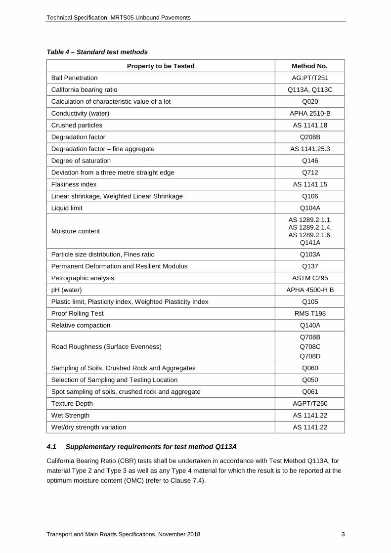
The standard test methods specified in Table 4 will be used in this Technical Specification.
Further details of test numbers and test descriptions are specified in Clause 4 of MRTS01 Introduction to Technical Specifications.
Technical Specification, MRTS05 Unbound Pavements
Transport and Main Roads Specifications, November 2018 3
Table 4 – Standard test methods
Property to be Tested Method No.
Ball Penetration AG:PT/T251
California bearing ratio Q113A, Q113C
Calculation of characteristic value of a lot Q020
Conductivity (water) APHA 2510-B
Crushed particles AS 1141.18
Degradation factor Q208B
Degradation factor – fine aggregate AS 1141.25.3
Degree of saturation Q146
Deviation from a three metre straight edge Q712
Flakiness index AS 1141.15
Linear shrinkage, Weighted Linear Shrinkage Q106
Liquid limit Q104A
Moisture content
AS 1289.2.1.1, AS 1289.2.1.4, AS 1289.2.1.6,
Q141A
Particle size distribution, Fines ratio Q103A
Permanent Deformation and Resilient Modulus Q137
Petrographic analysis ASTM C295
pH (water) APHA 4500-H B
Plastic limit, Plasticity index, Weighted Plasticity Index Q105
Proof Rolling Test RMS T198
Relative compaction Q140A
Road Roughness (Surface Evenness) Q708B Q708C Q708D
Sampling of Soils, Crushed Rock and Aggregates Q060
Selection of Sampling and Testing Location Q050
Spot sampling of soils, crushed rock and aggregate Q061
Texture Depth AGPT/T250
Wet Strength AS 1141.22
Wet/dry strength variation AS 1141.22 4.1 Supplementary requirements for test method Q113A
California Bearing Ratio (CBR) tests shall be undertaken in accordance with Test Method Q113A, for material Type 2 and Type 3 as well as any Type 4 material for which the result is to be reported at the optimum moisture content (OMC) (refer to Clause 7.4).

Technical Specification, MRTS05 Unbound Pavements
Transport and Main Roads Specifications, November 2018 4
For these materials, the test result shall be reported at the maximum dry density and optimum moisture content as defined by Test Method Q113A.
For other Type 4 materials (where a moisture content other than OMC is to be used – refer Clause 7.4), the CBR may be determined from one single-point test, in accordance with Test Method Q113C. This test shall be carried out at the maximum dry density of the material, and at the relative moisture content specified in Clause 2.4.2 of Annexure MRTS05.1.
Where a soaked CBR is specified, the soaking period shall be four days unless otherwise nominated in the design documents.
4.2 Supplementary requirements for test method AS 1141.22
The Wet Strength and the Wet/Dry Strength Variation tests shall both be carried out on the fraction of the coarse component passing the 13.2 mm test sieve but retained on the 9.5 mm test sieve.
However, for material which are specified with grading envelopes D or E, if sufficient material for the test cannot be obtained from this sieve range, the tests may be carried out on an alternative fraction approved by the Administrator. This will normally be the next coarse fraction which comprises 10% or more of the material and conforms with one of the component sizes listed in Test Method AS 1141.22.
5 Quality system requirements
5.1 Hold Points, Witness Points and Milestones
General requirements for Hold Points, Witness Points and Milestones are stated in Clause 5.2 of MRTS01 Introduction to Technical Specifications.
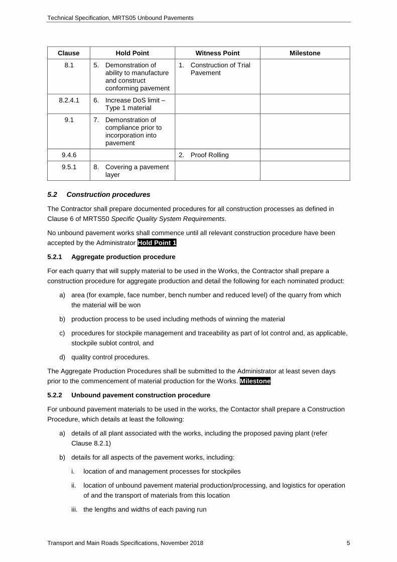
The Hold Points, Witness Points and Milestones applicable to this Technical Specification are summarised in Table 5.1.
Table 5.1 – Hold Points, Witness Points and Milestones
Clause Hold Point Witness Point Milestone
5.2 1. Acceptance of Construction Procedures for unbound pavement works
Submit Construction Procedure for aggregate production (7 days). Submit Construction Procedure for unbound pavement construction (14 days).
6 2. Use of quarry or source
Submit Quarry Registration Certificate (7 days). Submit Source Material Report (7 days).
7.2.4 3. Approval of grading envelope – Type 2
7.3.4 4. Approval of grading envelope – Type 3
Technical Specification, MRTS05 Unbound Pavements
Transport and Main Roads Specifications, November 2018 5
Clause Hold Point Witness Point Milestone
8.1 5. Demonstration of ability to manufacture and construct conforming pavement
1. Construction of Trial Pavement
8.2.4.1 6. Increase DoS limit – Type 1 material
9.1 7. Demonstration of compliance prior to incorporation into pavement
9.4.6 2. Proof Rolling
9.5.1 8. Covering a pavement layer
5.2 Construction procedures
The Contractor shall prepare documented procedures for all construction processes as defined in Clause 6 of MRTS50 Specific Quality System Requirements.
No unbound pavement works shall commence until all relevant construction procedure have been accepted by the Administrator Hold Point 1
5.2.1 Aggregate production procedure
For each quarry that will supply material to be used in the Works, the Contractor shall prepare a construction procedure for aggregate production and detail the following for each nominated product:
a) area (for example, face number, bench number and reduced level) of the quarry from which the material will be won
b) production process to be used including methods of winning the material
c) procedures for stockpile management and traceability as part of lot control and, as applicable, stockpile sublot control, and
d) quality control procedures.
The Aggregate Production Procedures shall be submitted to the Administrator at least seven days prior to the commencement of material production for the Works. Milestone
5.2.2 Unbound pavement construction procedure
For unbound pavement materials to be used in the works, the Contactor shall prepare a Construction Procedure, which details at least the following:
a) details of all plant associated with the works, including the proposed paving plant (refer Clause 8.2.1)
b) details for all aspects of the pavement works, including:
i. location of and management processes for stockpiles
ii. location of unbound pavement material production/processing, and logistics for operation of and the transport of materials from this location
iii. the lengths and widths of each paving run

Technical Specification, MRTS05 Unbound Pavements
Transport and Main Roads Specifications, November 2018 6
iv. the location and detail of joints required between each paving run
v. joint and surface preparation procedures
vi. procedures for the transport, placement, compaction and trimming of the pavement material
vii. details for working up to or against to structures, kerbs, road safety barriers, access chambers, drainage gullies and other fixed infrastructure within or adjacent to the pavement, including how the material will be placed and compacted to meet the minimum requirements of this Technical Specification, and
viii. procedure for proof rolling pavement layers.
c) process to provide traceability of unbound pavement materials from source through to material incorporated into the final pavement.
Where multiple unbound pavement materials are to be incorporated into the works, the Contractor may prepare a single procedure provided that any differences in construction process for each material are clearly noted.
The Unbound Pavement Construction Procedure shall be submitted to the Administrator at least 14 days prior to the commencement of unbound pavement works. Milestone
6 Quarry registration and source material assessment
The following applies to the Works:
a) The coarse component of Type 1, Type 2 (excluding Subtype 2.5) and Type 3 (excluding Subtype 3.5) materials shall each be supplied by a quarry registered and operated in accordance with the Transport and Main Roads Quarry Registration System requirements. The current Quarry Registration Certificate shall be submitted to the Administrator at least seven days before a material’s supply or use. Milestone
b) Where a Subtype 2.5, Subtype 3.5 or Type 4 material is not sourced from a quarry registered under the Quarry Registration System, for Contractor supplied material a source material assessment in accordance with Technical Note 140 Source Material Assessment for Subtype 2.5, Subtype 3.5 and Type 4 Unbound Pavement Materials shall be undertaken for the material source from which Subtype 2.5, Subtype 3.5 or Type 4 unbound pavement material is to be supplied. A copy of the Source Material Assessment Report shall be submitted to the Administrator at least seven days before supply or use. Milestone
c) The written permission of the Administrator to use the quarry or source is required prior to material being supplied to or used in the Works. Hold Point 2
Where any material is supplied by a quarry registered and operated in accordance with the Transport and Main Roads Quarry Registration System, and accordingly any changes are made to the Quarry Registration Certificate, including the associated Testing Frequency Schedule, Hold Point 2 shall be reapplied.

Technical Specification, MRTS05 Unbound Pavements
Transport and Main Roads Specifications, November 2018 7
7 Material
Unbound pavement materials specified in accordance with the Technical Specification have the following attributes:
Type 1 – High Standard Granular (HSG)
• A premium unbound granular pavement material, for use in the base course of heavy duty unbound pavements to produce a hard, durable and uniform material that enables a dense and homogeneous pavement to be constructed.
• typically covered with a sprayed seal or thin asphalt surfacing
• relies principally on the mobilisation of internal frictional forces to resist the applied load
• potentially highly permeable. Requires protection from moisture as soon as possible after construction. Will deteriorate rapidly if the wearing course fails
• permeability is reduced by specifying a minimum linear shrinkage requirement
• higher default compaction standard specified to provide some reduction in permeability as well as increased stiffness
• due to the minimal clay content, Type 1 materials typically have a very low unconfined strength. Consequently a single coat seal may not provide adequate confinement, particularly under heavy traffic, and at least a two coat polymer modified seal or asphalt surfacing should be applied
• must not be subject to traffic without a wearing course, and should be subject to traffic only for a very short period of time if it is covered by a prime only
• no direct strength test (CBR) is specified as optimum property limits are specified.
• because of the extensive range of properties chosen to specify this material, and because optimum property limits have been specified, Type 1 materials provide the highest probability of obtaining a consistently high quality pavement material
Type 2
• A high quality unbound granular pavement material, for use in base, sub-base and lower pavement layers
• relies principally on the mobilisation of internal frictional forces and/or cohesion to resist the applied load
• if a sprayed seal or asphalt wearing course is not provided, an appropriate minimum plasticity index or linear shrinkage requirement should be specified
• to comply with the relevant CBR requirement, the Contractor may have to apply more stringent target properties to the material within the limits given in this Technical Specification
• commonly used in wet environments, hence the specification of a soaked CBR requirement and more stringent durability requirements (compared to Type 3 materials)

Technical Specification, MRTS05 Unbound Pavements
Transport and Main Roads Specifications, November 2018 8
• historically, Type 2 materials were naturally occurring soil aggregate products, although the used of crushed quarry products has become increasingly popular over time
Type 3
• Attributes are as per Type 2, except intended for use in relatively dry environments only where the pavement equilibrium moisture content is low, hence the specification of an unsoaked CBR requirement. Similarly, only the 10% fines (wet) and the flakiness index properties for the course component are specified and the fines standards are less stringent than the values specified for Type 2 materials.
Type 4 - Non-standard material
• relies principally on cohesion but may also utilise the mobilisation of internal frictional forces to resist the applied load
• the only property specified for Type 4 materials is unsoaked CBR, to provide a hierarchy of the respective subtypes
• to utilise a Type 4 material, the designer must develop the standards and requirements relevant to the particular material and include these in the Annexure to MRTS05.1
Typical applications for each material subtype are given in Transport and Main Roads Pavement Design Supplement.
7.1 Type 1 unbound material - high standard granular (HSG)
7.1.1 General
Type 1 (HSG) material shall be hard, sound, durable and not breakdown in service.
The locations in which Type 1 (HSG) material is to be used shall be shown in the design documentation or specified in Clause 2.1 of Annexure MRTS05.1.
When properly constructed, a High Standard Granular (HSG) base provides a dense, relatively low-permeability structural layer, with increased durability. The HSG requirements of this Technical Specification are based on historically specified subtype 1.1 materials, modified to help ensure that this higher standard of pavement is able to be consistently achieved.
The use of Type 1 (HSG) materials in accordance with this Technical Specification has a number of specific requirements:
• material properties as specified in this Clause
• use of specific paving equipment and tighter process controls for adding moisture
• tighter controls on layer thickness and DoS
• texturing of the surface between layers, and
• checking of Post-compaction gradings and assessment of compaction using ‘modified compaction’ method.
Technical Specification, MRTS05 Unbound Pavements
Transport and Main Roads Specifications, November 2018 9
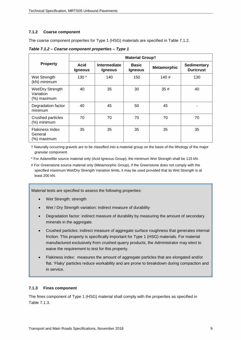
7.1.2 Coarse component
The coarse component properties for Type 1 (HSG) materials are specified in Table 7.1.2.
Table 7.1.2 – Coarse component properties – Type 1
Property Material Group†
Acid Igneous
Intermediate Igneous
Basic Igneous Metamorphic Sedimentary
Duricrust
Wet Strength (kN) minimum
130 * 140 150 140 # 130
Wet/Dry Strength Variation (%) maximum
40 35 30 35 # 40
Degradation factor minimum
40 45 50 45 -
Crushed particles (%) minimum
70 70 70 70 70
Flakiness Index General (%) maximum
35 35 35 35 35
† Naturally occurring gravels are to be classified into a material group on the basis of the lithology of the major granular component.
* For Adamellite source material only (Acid Igneous Group), the minimum Wet Strength shall be 115 kN.
# For Greenstone source material only (Metamorphic Group), if the Greenstone does not comply with the specified maximum Wet/Dry Strength Variation limits, it may be used provided that its Wet Strength is at least 200 kN.
Material tests are specified to assess the following properties:
• Wet Strength: strength
• Wet / Dry Strength variation: indirect measure of durability
• Degradation factor: indirect measure of durability by measuring the amount of secondary minerals in the aggregate.
• Crushed particles: indirect measure of aggregate surface roughness that generates internal friction. This property is specifically important for Type 1 (HSG) materials. For material manufactured exclusively from crushed quarry products, the Administrator may elect to waive the requirement to test for this property.
• Flakiness index: measures the amount of aggregate particles that are elongated and/or flat. ‘Flaky’ particles reduce workability and are prone to breakdown during compaction and in service.
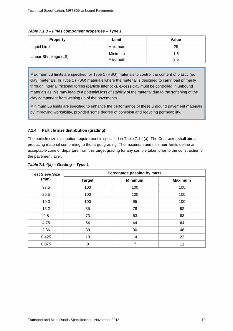
7.1.3 Fines component
The fines component of Type 1 (HSG) material shall comply with the properties as specified in Table 7.1.3.
Technical Specification, MRTS05 Unbound Pavements
Transport and Main Roads Specifications, November 2018 10
Table 7.1.3 – Fines component properties – Type 1
Property Limit Value
Liquid Limit Maximum 25
Linear Shrinkage (LS) Minimum Maximum
1.5 3.5
Maximum LS limits are specified for Type 1 (HSG) materials to control the content of plastic (ie. clay) materials. In Type 1 (HSG) materials where the material is designed to carry load primarily through internal frictional forces (particle interlock), excess clay must be controlled in unbound materials as this may lead to a potential loss of stability of the material due to the softening of the clay component from wetting up of the pavements.
Minimum LS limits are specified to enhance the performance of these unbound pavement materials by improving workability, provided some degree of cohesion and reducing permeability.
7.1.4 Particle size distribution (grading)
The particle size distribution requirement is specified in Table 7.1.4(a). The Contractor shall aim at producing material conforming to the target grading. The maximum and minimum limits define an acceptable zone of departure from this target grading for any sample taken prior to the construction of the pavement layer.
Table 7.1.4(a) – Grading – Type 1
Test Sieve Size (mm)
Percentage passing by mass
Target Minimum Maximum
37.5 100 100 100
26.5 100 100 100
19.0 100 95 100
13.2 85 78 92
9.5 73 63 83
4.75 54 44 64
2.36 39 30 48
0.425 18 14 22
0.075 9 7 11

Technical Specification, MRTS05 Unbound Pavements
Transport and Main Roads Specifications, November 2018 11
The following additional requirements shall apply to the particle size distribution specified in Table 7.1.4(a):
a) fines ratio, the ratio of the percentage of the material passing the 0.075 mm test sieve to the percentage of the material passing the 0.425 mm test sieve, shall be between the limits specified in Table 7.1.4(b), and
b) the grading curve for the material shall be smooth. Between adjacent sieves, the grading shall not vary from one outer third of the grading limits of one sieve to the opposite outer third of the grading limits of the next sieve.
Table 7.1.4(b) - Ratio of 0.075 mm material to 0.425 mm material – Type 1
Material Fines Ratio
Minimum Maximum
Type 1 0.30 0.55
The fines ratio can be related to unbound pavement material performance as follows:
• higher ratio – leads to a reduction in stability and strength, and
• lower ratio – increases permeability, poor surface finish, and reduces surface stability.
7.2 Type 2 unbound material
7.2.1 General
Type 2 material, excluding Subtype 2.5, shall comply where applicable with the following requirements:
a) any component retained on the 2.36 mm test sieve shall be manufactured only from source material from a quarry which has a current Quarry Registration Certificate and will produce the coarse component of the final product which complies with the relevant properties specified in Table 7.2.2, and
b) any component passing the 2.36 mm test sieve and retained on the 0.425 mm test sieve (ie sand size) shall be obtained from either a natural deposit in which the individual grains are hard and durable or a crushed rock source which has current certification and from which the coarse component complies with the properties specified in Table 7.2.2.
c) Supplementary fine material can be imported to overcome grading and/or plastic property deficiencies provided it is durable, complies with the above requirements and the requirements of Clause 7.2.3.
The locations in which material of a specific subtype is to be used shall be shown in the design documentation or specified in Clause 2.1 of Annexure MRTS05.1.
Technical Specification, MRTS05 Unbound Pavements
Transport and Main Roads Specifications, November 2018 12
The strength of Type 2 material is principally assessed by the soaked California Bearing Ratio (CBR) test (Test Method Q113A). To consistently comply with all of the relevant specification requirements, it may be necessary for the Contractor to develop a set of secondary requirements which comply with the list of primary requirements specified in Clauses 7.2.2, 7.2.3 and 7.2.4 but, where necessary, are more stringent so that the specified CBR is achieved.
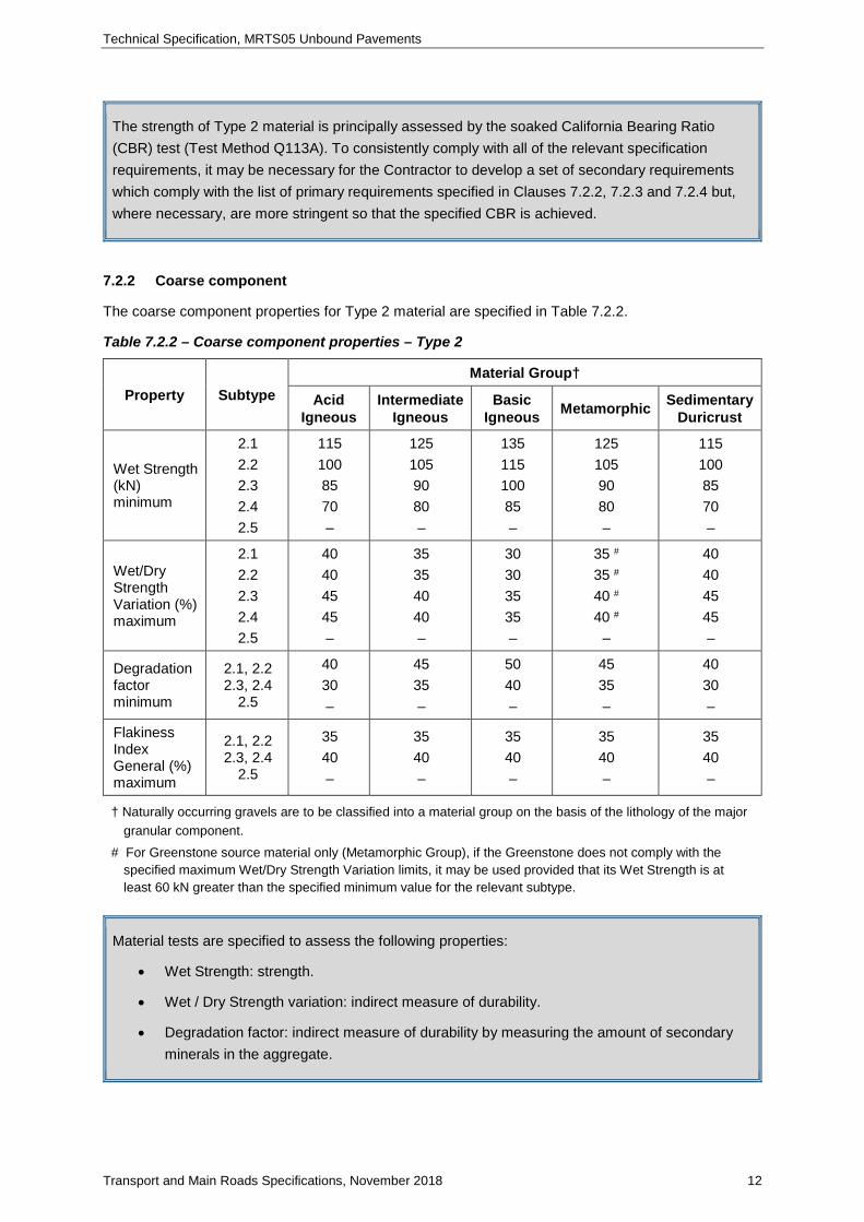
7.2.2 Coarse component
The coarse component properties for Type 2 material are specified in Table 7.2.2.
Table 7.2.2 – Coarse component properties – Type 2
Property Subtype Material Group†
Acid Igneous
Intermediate Igneous
Basic Igneous Metamorphic Sedimentary
Duricrust
Wet Strength (kN) minimum
2.1 2.2 2.3 2.4 2.5
115 100 85 70 –
125 105 90 80 –
135 115 100 85 –
125 105 90 80 –
115 100 85 70 –
Wet/Dry Strength Variation (%) maximum
2.1 2.2 2.3 2.4 2.5
40 40 45 45 –
35 35 40 40 –
30 30 35 35 –
35 # 35 # 40 # 40 #
–
40 40 45 45 –
Degradation factor minimum
2.1, 2.2 2.3, 2.4
2.5
40 30 –
45 35 –
50 40 –
45 35 –
40 30 –
Flakiness Index General (%) maximum
2.1, 2.2 2.3, 2.4
2.5
35 40 –
35 40 –
35 40 –
35 40 –
35 40 –
† Naturally occurring gravels are to be classified into a material group on the basis of the lithology of the major granular component.
# For Greenstone source material only (Metamorphic Group), if the Greenstone does not comply with the specified maximum Wet/Dry Strength Variation limits, it may be used provided that its Wet Strength is at least 60 kN greater than the specified minimum value for the relevant subtype.
Material tests are specified to assess the following properties:
• Wet Strength: strength.
• Wet / Dry Strength variation: indirect measure of durability.
• Degradation factor: indirect measure of durability by measuring the amount of secondary minerals in the aggregate.
Technical Specification, MRTS05 Unbound Pavements
Transport and Main Roads Specifications, November 2018 13
• Flakiness index: measures the amount of aggregate particles that are elongated and/or flat. ‘Flaky’ particles reduce workability and are prone to breakdown during compaction and in service.
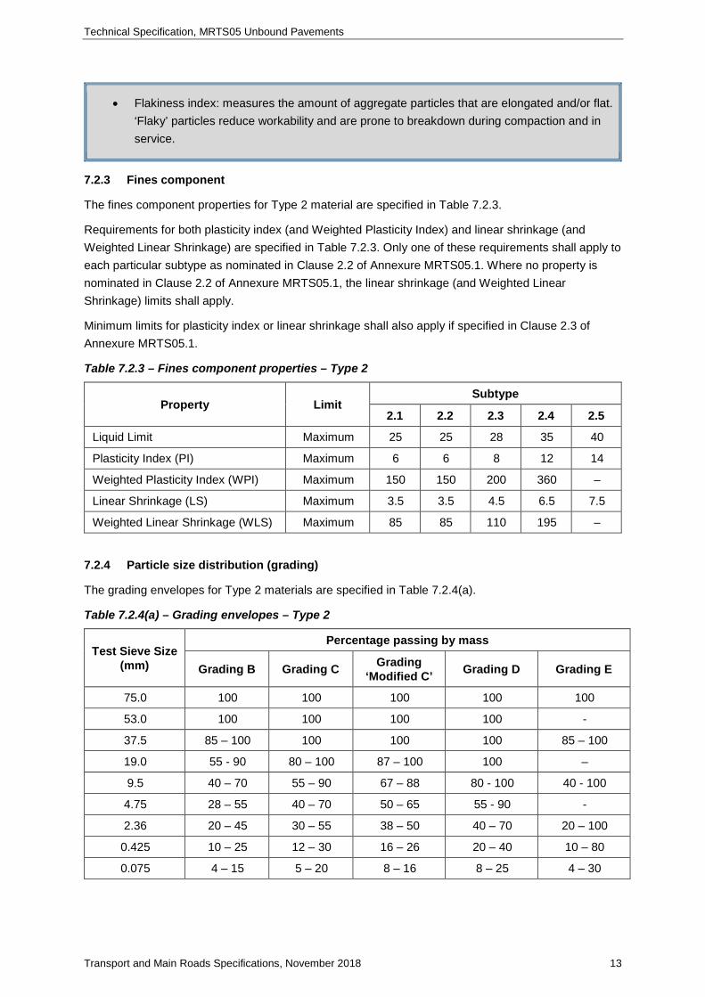
7.2.3 Fines component
The fines component properties for Type 2 material are specified in Table 7.2.3.
Requirements for both plasticity index (and Weighted Plasticity Index) and linear shrinkage (and Weighted Linear Shrinkage) are specified in Table 7.2.3. Only one of these requirements shall apply to each particular subtype as nominated in Clause 2.2 of Annexure MRTS05.1. Where no property is nominated in Clause 2.2 of Annexure MRTS05.1, the linear shrinkage (and Weighted Linear Shrinkage) limits shall apply.
Minimum limits for plasticity index or linear shrinkage shall also apply if specified in Clause 2.3 of Annexure MRTS05.1.
Table 7.2.3 – Fines component properties – Type 2
Property Limit Subtype
2.1 2.2 2.3 2.4 2.5
Liquid Limit Maximum 25 25 28 35 40
Plasticity Index (PI) Maximum 6 6 8 12 14
Weighted Plasticity Index (WPI) Maximum 150 150 200 360 –
Linear Shrinkage (LS) Maximum 3.5 3.5 4.5 6.5 7.5
Weighted Linear Shrinkage (WLS) Maximum 85 85 110 195 –
7.2.4 Particle size distribution (grading)
The grading envelopes for Type 2 materials are specified in Table 7.2.4(a).
Table 7.2.4(a) – Grading envelopes – Type 2
Test Sieve Size (mm)
Percentage passing by mass
Grading B Grading C Grading ‘Modified C’ Grading D Grading E
75.0 100 100 100 100 100
53.0 100 100 100 100 -
37.5 85 – 100 100 100 100 85 – 100
19.0 55 - 90 80 – 100 87 – 100 100 –
9.5 40 – 70 55 – 90 67 – 88 80 - 100 40 - 100
4.75 28 – 55 40 – 70 50 – 65 55 - 90 -
2.36 20 – 45 30 – 55 38 – 50 40 – 70 20 – 100
0.425 10 – 25 12 – 30 16 – 26 20 – 40 10 – 80
0.075 4 – 15 5 – 20 8 – 16 8 – 25 4 – 30

Technical Specification, MRTS05 Unbound Pavements
Transport and Main Roads Specifications, November 2018 14
The following additional requirements shall apply to the grading envelopes specified in Table 7.2.4(a):
a) fines ratio, the ratio of the percentage of the material passing the 0.075 mm test sieve to the percentage of the material passing the 0.425 mm test sieve, shall be between the limits specified in Table 7.2.4(b), and
b) Where grading B, C, ‘Modified C’ or D is specified the grading curve for the material shall be smooth. With the exception of ‘Modified C’ grading, between adjacent sieves, the grading shall not vary from one outer third of the grading limits of one sieve to the opposite outer third of the grading limits of the next sieve.
The “Modified C” grading has been introduced with the intent of standardising project-specific local practices. Before nominating the “Modified C” grading, if it has not been used previously, it is recommended that the Transport and Main Roads District investigate the feasibility of obtaining this tighter grading from local sources. Depending on rock type and crusher capability, mix adjustment/s to assure compliance with both this tighter grading and all other requirements may require allowance/s for additional time and/or cost. For further advice prior to specifying ‘Modified C’ grading in Departmental projects, the Transport and Main Roads District should consult with the Director (Pavements Rehabilitation) or their nominee.
Table 7.2.4(b) – Ratio of 0.075 mm material to 0.425 mm material – Type 2
Subtype Fines Ratio
Minimum Maximum
2.1 0.30 0.55
2.2, 2.3 0.30 0.65
2.4, 2.5 – –
The fines ratio can be related to unbound pavement material performance as follows:
• higher ratio – leads to a reduction in stability and strength
• lower ratio – increases permeability, poor surface finish, and reduces surface stability
The acceptable grading envelope shall be in accordance with the requirements specified in Table 7.2.4(c) and the nominated grading envelopes to be used for various locations under the Contract are specified in Clause 2.1 of Annexure MRTS05.1.

Technical Specification, MRTS05 Unbound Pavements
Transport and Main Roads Specifications, November 2018 15
Table 7.2.4(c) – Acceptable gradings – Type 2
Subtype Acceptable Gradings
2.1 B, C or ‘Modified C’
2.2 and 2.3 B, C, ‘Modified C’ or D
2.4 and 2.5 if used in a base or upper subbase layer
B, C, ‘Modified C’ or D
2.4 and 2.5 if used in a layer other than a base or upper
subbase
Any
If more than one grading envelope is specified in Clause 2.1 of Annexure MRTS05.1 for a single location, the Contractor shall notify the Administrator in writing, at least two working days before the commencement of the production of materials for the works, which of the grading envelopes will be used Hold Point 3
If the Contractor wishes to use an alternative grading nominated in Clause 2.1 of Annexure MRTS05.1, Hold Point 3 shall be resubmitted at least two working days before the commencement of the production of materials for the works
7.2.5 California bearing ratio
The California Bearing Ratio requirements for Type 2 material are specified in Table 7.2.5.
Table 7.2.5 – California bearing ratio requirements – Type 2
Property Limit Subtype
2.1 2.2 2.3 2.4 2.5
CBR (soaked) Minimum 80 60 45 35 15
7.3 Type 3 unbound material
7.3.1 General
Type 3 material, excluding Subtype 3.5, shall comply where applicable with the following requirements:
a) any component retained on the 2.36 mm test sieve shall be manufactured only from source material from a quarry which has a current Quarry Registration Certificate and will produce the coarse component of the final product which complies with the relevant properties given in Table 7.3.2, and
b) any component passing the 2.36 mm test sieve and retained on the 0.425 mm test sieve (i.e. sand size) shall be obtained from either a natural deposit in which the individual grains are hard and durable or a crushed rock source which has a current Quarry Registration Certificate and from which the coarse component complies with the properties specified in Table 7.3.2.
c) Supplementary fine material can be imported to overcome grading and/or plastic property deficiencies provided it is durable, complies with the above requirements and the requirements of Clause 7.3.2.
Technical Specification, MRTS05 Unbound Pavements
Transport and Main Roads Specifications, November 2018 16
The locations in which material of a specific subtype is to be used shall be shown in the design documentation or specified in Clause 2.1 of Annexure MRTS05.1.
The strength of Type 3 material is principally assessed by the soaked California Bearing Ratio (CBR) test (Test Method Q113A). To consistently comply with all of the relevant specification requirements, it may be necessary for the Contractor to develop a set of secondary requirements which comply with the list of primary requirements specified in Clauses 7.3.2, 7.3.3 and 7.3.4 but, where necessary, are more stringent so that the specified CBR is achieved.
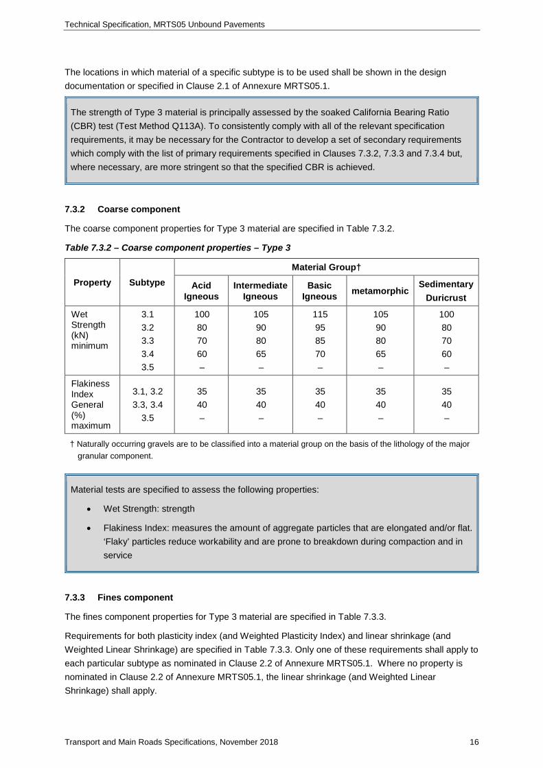
7.3.2 Coarse component
The coarse component properties for Type 3 material are specified in Table 7.3.2.
Table 7.3.2 – Coarse component properties – Type 3
Property Subtype Material Group†
Acid Igneous
Intermediate Igneous
Basic Igneous metamorphic
Sedimentary Duricrust
Wet Strength (kN) minimum
3.1 3.2 3.3 3.4 3.5
100 80 70 60 –
105 90 80 65 –
115 95 85 70 –
105 90 80 65 –
100 80 70 60 –
Flakiness Index General (%) maximum
3.1, 3.2 3.3, 3.4
3.5
35 40 –
35 40 –
35 40 –
35 40 –
35 40 –
† Naturally occurring gravels are to be classified into a material group on the basis of the lithology of the major granular component.
Material tests are specified to assess the following properties:
• Wet Strength: strength
• Flakiness Index: measures the amount of aggregate particles that are elongated and/or flat. ‘Flaky’ particles reduce workability and are prone to breakdown during compaction and in service
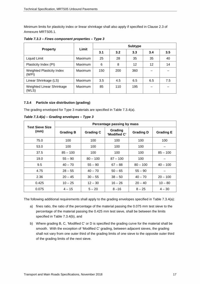
7.3.3 Fines component
The fines component properties for Type 3 material are specified in Table 7.3.3.
Requirements for both plasticity index (and Weighted Plasticity Index) and linear shrinkage (and Weighted Linear Shrinkage) are specified in Table 7.3.3. Only one of these requirements shall apply to each particular subtype as nominated in Clause 2.2 of Annexure MRTS05.1. Where no property is nominated in Clause 2.2 of Annexure MRTS05.1, the linear shrinkage (and Weighted Linear Shrinkage) shall apply.
Technical Specification, MRTS05 Unbound Pavements
Transport and Main Roads Specifications, November 2018 17
Minimum limits for plasticity index or linear shrinkage shall also apply if specified in Clause 2.3 of Annexure MRTS05.1.
Table 7.3.3 – Fines component properties – Type 3
Property Limit Subtype
3.1 3.2 3.3 3.4 3.5
Liquid Limit Maximum 25 28 35 35 40
Plasticity Index (PI) Maximum 6 8 12 12 14
Weighted Plasticity Index (WPI)
Maximum 150 200 360 – –
Linear Shrinkage (LS) Maximum 3.5 4.5 6.5 6.5 7.5
Weighted Linear Shrinkage (WLS)
Maximum 85 110 195 – –
7.3.4 Particle size distribution (grading)
The grading enveloped for Type 3 materials are specified in Table 7.3.4(a).
Table 7.3.4(a) – Grading envelopes – Type 3
Test Sieve Size (mm)
Percentage passing by mass
Grading B Grading C Grading ‘Modified C’ Grading D Grading E
75.0 100 100 100 100 100
53.0 100 100 100 100 –
37.5 85 – 100 100 100 100 85 – 100
19.0 55 – 90 80 – 100 87 – 100 100 –
9.5 40 – 70 55 – 90 67 – 88 80 – 100 40 – 100
4.75 28 – 55 40 – 70 50 – 65 55 – 90 –
2.36 20 – 45 30 – 55 38 – 50 40 – 70 20 – 100
0.425 10 – 25 12 – 30 16 – 26 20 – 40 10 – 80
0.075 4 – 15 5 – 20 8 –16 8 – 25 4 – 30 The following additional requirements shall apply to the grading envelopes specified in Table 7.3.4(a):
a) fines ratio, the ratio of the percentage of the material passing the 0.075 mm test sieve to the percentage of the material passing the 0.425 mm test sieve, shall be between the limits specified in Table 7.3.4(b), and
b) Where grading B, C, ‘Modified C’ or D is specified the grading curve for the material shall be smooth. With the exception of ‘Modified C’ grading, between adjacent sieves, the grading shall not vary from one outer third of the grading limits of one sieve to the opposite outer third of the grading limits of the next sieve.

Technical Specification, MRTS05 Unbound Pavements
Transport and Main Roads Specifications, November 2018 18
The “Modified C” grading has been introduced with the intent of standardising project-specific local practices. Before nominating the “Modified C” grading, if it has not been used previously, it is recommended that the Transport and Main Roads District investigate the feasibility of obtaining this tighter grading from local sources. Depending on rock type and crusher capability, mix adjustment/s to assure compliance with both this tighter grading and all other requirements may require allowance/s for additional time and/or cost. For further advice prior to specifying “Modified C’ grading in Departmental projects, the Transport and Main Roads District should consult with the Director (Pavements Rehabilitation) or their nominee
Table 7.3.4(b) – Ratio of 0.075 mm material to 0.425 mm material – Type 3
Subtype Fines Ratio
Minimum Maximum
3.1 0.35 0.55
3.2, 3.3 0.35 0.65
3.4, 3.5 – –
The fines ratio can be related to unbound pavement material performance as follows:
• higher ratio – leads to a reduction in stability and strength
• lower ratio – increases permeability, poor surface finish, and reduces surface stability
The acceptable grading envelope shall be in accordance with the requirements specified in Table 7.3.4(c) and the nominated grading envelopes to be used for various locations under the Contract are specified in Clause 2.1 of Annexure MRTS05.1.
Table 7.3.4(c) – Acceptable gradings – Type 3
Subtype Acceptable Gradings
3.1 B, C or ‘Modified C’
3.2 and 3.3 B, C, ‘Modified C’ or D
3.4 and 3.5 if used in a base or upper subbase layer
B, C, ‘Modified C’ or D
3.4 and 3.5 if used in a layer other than a base or upper
subbase Any
If more than one grading envelope is specified in Clause 2.1 of Annexure MRTS05.1 for a single location, the Contractor shall notify the Administrator in writing, at least two working days before the commencement of the production of materials for the works, which of the grading envelopes will be used Hold Point 4
If the Contractor wishes to use an alternative grading nominated in Clause 2.1 of Annexure MRTS05.1, Hold Point 4 shall be resubmitted at least two working days before the commencement of the production of materials for the works.
Technical Specification, MRTS05 Unbound Pavements
Transport and Main Roads Specifications, November 2018 19
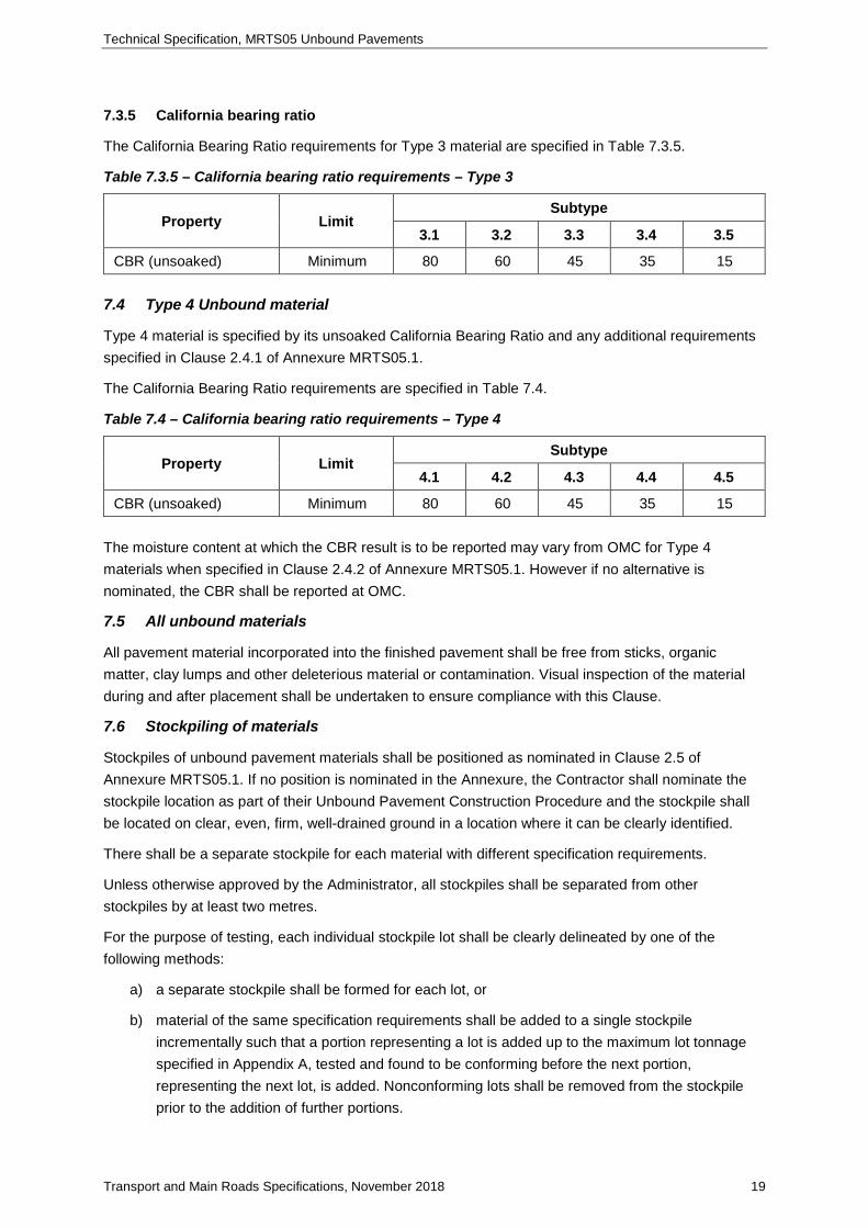
7.3.5 California bearing ratio
The California Bearing Ratio requirements for Type 3 material are specified in Table 7.3.5.
Table 7.3.5 – California bearing ratio requirements – Type 3
Property Limit Subtype
3.1 3.2 3.3 3.4 3.5
CBR (unsoaked) Minimum 80 60 45 35 15 7.4 Type 4 Unbound material
Type 4 material is specified by its unsoaked California Bearing Ratio and any additional requirements specified in Clause 2.4.1 of Annexure MRTS05.1.
The California Bearing Ratio requirements are specified in Table 7.4.
Table 7.4 – California bearing ratio requirements – Type 4
Property Limit Subtype
4.1 4.2 4.3 4.4 4.5
CBR (unsoaked) Minimum 80 60 45 35 15 The moisture content at which the CBR result is to be reported may vary from OMC for Type 4 materials when specified in Clause 2.4.2 of Annexure MRTS05.1. However if no alternative is nominated, the CBR shall be reported at OMC.
7.5 All unbound materials
All pavement material incorporated into the finished pavement shall be free from sticks, organic matter, clay lumps and other deleterious material or contamination. Visual inspection of the material during and after placement shall be undertaken to ensure compliance with this Clause.
7.6 Stockpiling of materials
Stockpiles of unbound pavement materials shall be positioned as nominated in Clause 2.5 of Annexure MRTS05.1. If no position is nominated in the Annexure, the Contractor shall nominate the stockpile location as part of their Unbound Pavement Construction Procedure and the stockpile shall be located on clear, even, firm, well-drained ground in a location where it can be clearly identified.
There shall be a separate stockpile for each material with different specification requirements.
Unless otherwise approved by the Administrator, all stockpiles shall be separated from other stockpiles by at least two metres.
For the purpose of testing, each individual stockpile lot shall be clearly delineated by one of the following methods:
a) a separate stockpile shall be formed for each lot, or
b) material of the same specification requirements shall be added to a single stockpile incrementally such that a portion representing a lot is added up to the maximum lot tonnage specified in Appendix A, tested and found to be conforming before the next portion, representing the next lot, is added. Nonconforming lots shall be removed from the stockpile prior to the addition of further portions.
Technical Specification, MRTS05 Unbound Pavements
Transport and Main Roads Specifications, November 2018 20
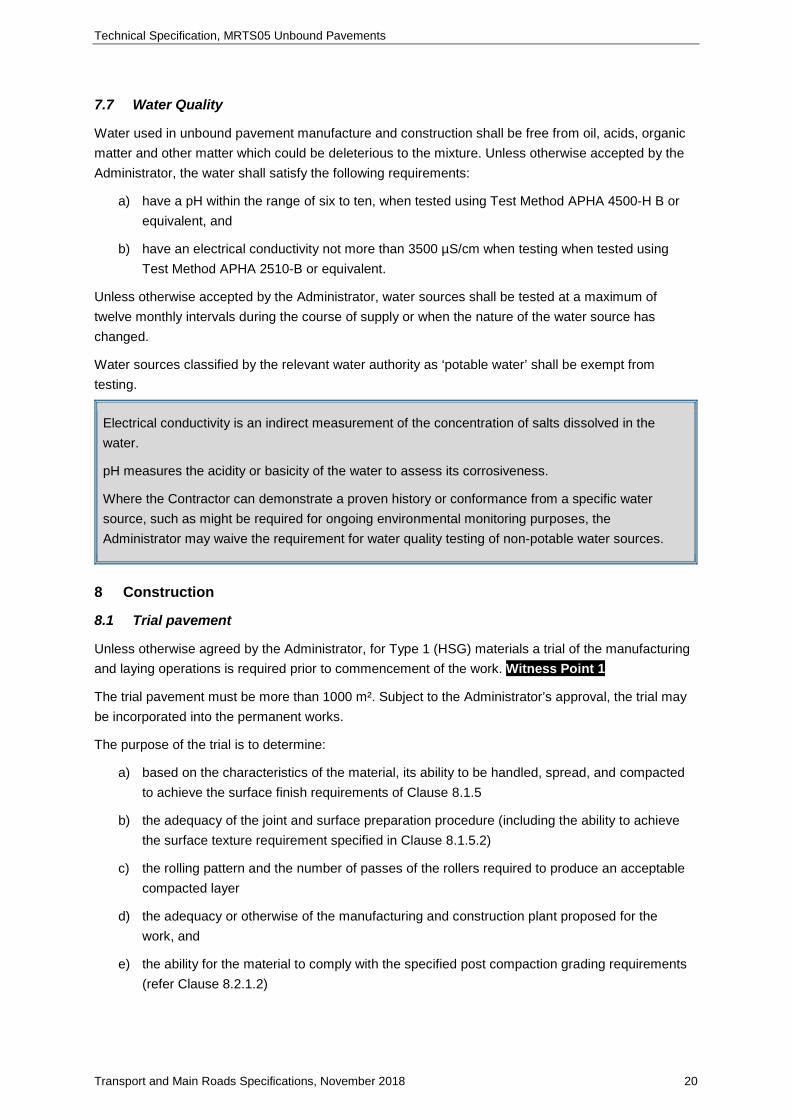
7.7 Water Quality
Water used in unbound pavement manufacture and construction shall be free from oil, acids, organic matter and other matter which could be deleterious to the mixture. Unless otherwise accepted by the Administrator, the water shall satisfy the following requirements:
a) have a pH within the range of six to ten, when tested using Test Method APHA 4500-H B or equivalent, and
b) have an electrical conductivity not more than 3500 µS/cm when testing when tested using Test Method APHA 2510-B or equivalent.
Unless otherwise accepted by the Administrator, water sources shall be tested at a maximum of twelve monthly intervals during the course of supply or when the nature of the water source has changed.
Water sources classified by the relevant water authority as ‘potable water’ shall be exempt from testing.
Electrical conductivity is an indirect measurement of the concentration of salts dissolved in the water.
pH measures the acidity or basicity of the water to assess its corrosiveness.
Where the Contractor can demonstrate a proven history or conformance from a specific water source, such as might be required for ongoing environmental monitoring purposes, the Administrator may waive the requirement for water quality testing of non-potable water sources.
8 Construction
8.1 Trial pavement
Unless otherwise agreed by the Administrator, for Type 1 (HSG) materials a trial of the manufacturing and laying operations is required prior to commencement of the work. Witness Point 1
The trial pavement must be more than 1000 m². Subject to the Administrator’s approval, the trial may be incorporated into the permanent works.
The purpose of the trial is to determine:
a) based on the characteristics of the material, its ability to be handled, spread, and compacted to achieve the surface finish requirements of Clause 8.1.5
b) the adequacy of the joint and surface preparation procedure (including the ability to achieve the surface texture requirement specified in Clause 8.1.5.2)
c) the rolling pattern and the number of passes of the rollers required to produce an acceptable compacted layer
d) the adequacy or otherwise of the manufacturing and construction plant proposed for the work, and
e) the ability for the material to comply with the specified post compaction grading requirements (refer Clause 8.2.1.2)

Technical Specification, MRTS05 Unbound Pavements
Transport and Main Roads Specifications, November 2018 21
The Contractor shall carry out material and construction compliance tests in accordance with Clause 9 to confirm the trial complies with the requirements of this Technical Specification. Prior to continuing works after completion of the trial, the Contractor shall submit to the Administrator, for their acceptance, records which demonstrate this compliance Hold Point 5 If the trial does not conform in full to the requirements of this Technical Specification, the Contractor shall review their construction procedure and the properties of the proposed unbound materials and a further trial shall be undertaken.
Where minor nonconformances occur in a trial, and the Administrator accepts to incorporate the lot into the permanent works (either at a reduced level of service or otherwise), the Administrator, at their sole discretion may elect to waive the requirement for a further trial to be undertaken.
However where more significant nonconformances occur, and these or other nonconformances occur again after a further trial, the Contractor should substantially review their construction procedure and proposed materials.
8.2 Process requirements
8.2.1 Paving Equipment
8.2.1.1 General
For pavements constructed, using Type 2, 3 or 4 materials, specific equipment shall be used as stated in Clause 3.1 of Annexure MRTS05.1.
For pavement constructed using Type 1 materials, the requirements of Clause 8.2.1.2 shall apply.
Where no specific equipment is nominated in Clause 3.1 of Annexure MRTS05.1, or the Administrator approves the use of alternative equipment in accordance with Clause 8.2.1.2, the Contractor shall nominate the paving equipment to be used in their Unbound Pavement Construction Procedure.
Irrespective of what equipment is used, the mix shall be placed and spread such that there is no segregation of the mixture.
8.2.1.2 Paving Type 1 material
Pavements incorporating Type 1 (HSG) materials shall be constructed using a self-propelled spreading machine purpose-built for this work (that is, a paver). Such machines shall have the capacity to either:
a) receive the material in a hopper and place and spread the material on the prepared surface to the required uncompacted layer thickness, width and shape in one pass, or
b) spread previously placed windrows of the material to the required uncompacted layer thickness, width and shape in one pass.
The Administrator may approve other methods of paving (for example, using a grader) in areas where the pavement width is such that the use of a paver is not practical.
8.2.2 Paving
Unbound pavements shall be constructed such that each individual layer is laid in one pass that meets the requirements of this Technical Specification without the addition of extra material except as detailed below.

Technical Specification, MRTS05 Unbound Pavements
Transport and Main Roads Specifications, November 2018 22
The material laid ready for compaction shall not have any visible areas of segregation. Any segregated areas are to be removed and replaced with fresh mix prior to the commencement of compaction of the lot. Material removed for this reason shall be disposed of in accordance with Clause 10 of MRTS01 Introduction to Technical Specifications and shall trigger a nonconformance, under which the Contractor must identify the cause of the segregation and propose preventative action to prevent reoccurrence Nonconformance
8.2.3 Layer thicknesses
Individual compacted layer thicknesses shall be chosen to suit the construction process and the requirements of the Contract. Unless otherwise approved by the Administrator, the completed layer thicknesses (after compaction and surface preparation) shall be in accordance with Table 8.2.3.
Table 8.2.3 – Layer thickness requirements
Material Minimum Value Maximum Value
Type 1 (HSG) 100 mm 150 mm
All other subtypes 75 mm 250 mm Where multiple layers of the same material are placed together in a single course each layer shall be of equal thickness
8.2.4 Moisture content
8.2.4.1 Moisture Content prior to covering
The pavement layer shall have a moisture content such that the degree of saturation is less than the relevant limit specified in Table 8.2.4.1 at the time that it is covered by another pavement layer or surfacing. Unless otherwise accepted by the Administrator, these requirements shall also apply to trafficking unbound pavement layers.
Table 8.2.4.1 – Maximum degree of saturation
Material Maximum Degree of Saturation (%)
Type 1 (HSG) 60 *
Type 2 65
Type 3 70
Type 4 70
* For Type 1 material, the Administrator may accept a higher degree of saturation limit (up to a maximum of 70%) when the Contractor Hold Point 6:
a) confirms the use of a higher moisture content limit will not impact on achieving the surface finish requirements stated in Clause 8.2.5, and
b) demonstrates adequate resistance to deformation at a higher DOS level. This demonstration shall at least include RLT testing in accordance with Test Method Q137 where the maximum DOS at the time of sealing shall be the maximum value providing:
i. less than 1.5% permanent strain after 1000 cycles
ii. less than 4.0% strain at 50,000 cycles, and
iii. RLT test results shall be undertaken on the manufactured pavement material not more than 12 months prior to its intended incorporation into the works.
Technical Specification, MRTS05 Unbound Pavements
Transport and Main Roads Specifications, November 2018 23
A common factor affecting the premature failure of newly constructed unbound granular pavements has been the presence of excess moisture within the pavement base prior to the application of the bituminous surfacing. A degree of saturation above the specified limits can lead to:
• rapid failure including blow-outs and rutting of an unbound pavement layer due to shear failures
• lifting of the wearing course due to positive pore pressure, and
• embedment of cover aggregate in the wearing course due to softening of the unbound base.
8.2.4.2 Moisture content during construction
The unbound pavement material may have a moisture content greater than that represented by the relevant degree of saturation limit specified in Clause 8.2.4.1 for the purpose of construction only, provided that the section of pavement is dried back to meet the requirements of Clause 8.2.4.1 at the time it is covered by another pavement or surfacing layer.
For Type 1 (HSG) material, water shall only be added to the unbound pavement material via a controlled and measured process and be uniformly mixed through the material using a pugmill (or equivalent mechanical process).
Sufficient moisture must be added to unbound pavement material to allow adequate lubrication of the particles to achieve compaction. Generally unbound materials should be compacted near OMC to achieve maximum density, however materials are often compacted slightly dry of OMC to reduce the time required to achieve dry back. For Type 1 (HSG) materials, a higher moisture content may be required to achieve the higher standard of compaction specified.
Developing optimum moisture content and density graphs for the material can be useful to characterise the material, indicate sensitivity to water content and inform compaction procedures. However, the required moisture content for field compaction will depend largely on the conditions onsite and must be chosen to align with the materials characteristics and the compaction equipment to be used.
Uniformity of moisture content in the material is important as variations will likely affect compactability, leading to unsatisfactory variations in density.
Wet-mixing unbound pavement materials prior to delivery to the roadbed will assist in minimising segregation during the spreading stage. However the type and capacity of the pugmill will determine the length of the mixing time. Too short a mixing time in the pugmill will result in uneven moisture content throughout the product and will adversely impact on the ability to readily achieve the required compaction result.
Technical Specification, MRTS05 Unbound Pavements
Transport and Main Roads Specifications, November 2018 24
8.2.5 Surface finish
8.2.5.1 General
The finished surface of any unbound pavement layer shall:
• be hard and homogenous in appearance
• not have any loose, segregated or contaminated areas
• have the course particles slightly exposed
• not be affected by delamination
• not show signs of water pumping, and
• not visibly deflect under load when proof rolled in accordance with Clause 9.4.6.
For layers that are to be covered be a sprayed bituminous treatment, the surface shall have a maximum ball penetration value of 3.0 mm when tested in accordance with Clause 9.4.7
As necessary, the Contractor shall trim, lightly water, broom and roll the pavement to achieve the above finish to the satisfaction of the Administrator.
It is intended that these requirements apply to the condition of the pavement surface immediately prior to application of the surfacing treatment/ layer. The Contractor may need to undertake additional controls beyond the basic construction activities (compaction, trimming and so on) to ensure these requirements are satisfied.
8.2.5.2 Preparation of Type 1 layers prior to placing the next layer
Where a Type 1 (HSG) layer is to be overlaid directly with another layer of Type 1 material, the finished surface shall be prepared so that it has a hard rough surface with a texture depth not less than 1 mm (when testing in accordance with Test Method AGPT/T250) without reducing the density of the layer or compromising the integrity of the surface.
The Contractor will nominate in their Construction Procedure the proposed methodology to prepare the pavement. This may be undertaken by hard brooming using a drag broom, however other plant may be used dependent on the nature of the project and what equipment is available onsite for other processes.
Unless otherwise approved by the Administrator, the overlying layer of type 1 material must be constructed within three days of the construction of the underlying layer unless additional time is required to dry back the underlying layer. Where additional time is needed to dry back the underlying layer, the overlying layer shall be constructed as soon as the required degree of saturation has been reached.
All cut back material shall be disposed of in accordance with Clause 10 of MRTS01 Introduction to Technical Specifications.
Technical Specification, MRTS05 Unbound Pavements
Transport and Main Roads Specifications, November 2018 25
8.2.6 Construction joints between adjacent paving runs
To the extent practical, the Contractor shall spread the unbound pavement material in a manner that minimises the number of joints.
Joints shall be constructed such that the material at the joints comply in all ways with the requirements of this Technical Specification.
Longitudinal joints must comply with the following requirements unless otherwise approved by the Administrator:
a) Joints shall be offset by a minimum of 150 mm from a joint in the underlying layers, except where required otherwise to achieve the design shape (for example to construct a crowned pavement), and
b) Joints in the final (uppermost) layer of unbound pavement material shall be located within 300 mm of the planned position of the final traffic lane marking.
Transverse joints must be offset by a minimum of 2.0 m from a joint in any underlying layer, unless otherwise approved by the Administrator.
The Administrator may approve pavement joints to be constructed away from lane marking where this represents the best outcome to achieve the pavement design intent. For example, when paving a single lane ramp with wide shoulders, the Administrator may allow the Contractor to form a single longitudinal joint along the centre of the ramp rather than paving the ramp lane between the edge line marking and the subsequently paving narrow shoulders on either side.
8.2.7 Contractors responsibilities
The Contractor shall maintain each layer such that it complies with all aspects of this Technical Specification until it has been overlaid with another pavement layer or surfaced with the final wearing surface, and then until the end of the defect liability period or as otherwise required under the Contract.
8.2.8 Dust management
Unbound pavement material shall be transported and delivered with sufficient moisture to control dust.
Unless other specific dust management practices are in place, unbound pavement material should not be handled dry. The moisture content required to manage dust will vary from material to material, however would generally be less than that required to place and compact the material as a conforming pavement layer.
8.3 Product standards
8.3.1 Segregation
Segregation is the uneven distribution of particle sizes. The construction process shall control segregation so that the particle size distribution of the unbound pavement material complies with the particle size distribution requirements in Clause 7 (for the relevant subtype and grading) prior to the commencement of compaction.
Technical Specification, MRTS05 Unbound Pavements
Transport and Main Roads Specifications, November 2018 26
Where there are visible signs of segregation in any lot prior to the commencement of compaction, the Administrator may direct the area to be tested for conformance with the above requirements.
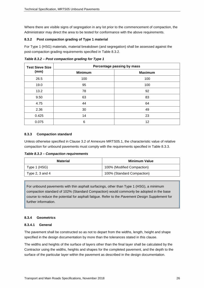
8.3.2 Post compaction grading of Type 1 material
For Type 1 (HSG) materials, material breakdown (and segregation) shall be assessed against the post-compaction grading requirements specified in Table 8.3.2.
Table 8.3.2 – Post compaction grading for Type 1
Test Sieve Size (mm)
Percentage passing by mass
Minimum Maximum
26.5 100 100
19.0 95 100
13.2 78 92
9.50 63 83
4.75 44 64
2.36 30 49
0.425 14 23
0.075 6 12
8.3.3 Compaction standard
Unless otherwise specified in Clause 3.2 of Annexure MRTS05.1, the characteristic value of relative compaction for unbound pavements must comply with the requirements specified in Table 8.3.3.
Table 8.3.3 – Compaction requirements
Material Minimum Value
Type 1 (HSG) 100% (Modified Compaction)
Type 2, 3 and 4 100% (Standard Compaction)
For unbound pavements with thin asphalt surfacings, other than Type 1 (HSG), a minimum compaction standard of 102% (Standard Compaction) would commonly be adopted in the base course to reduce the potential for asphalt fatigue. Refer to the Pavement Design Supplement for further information.
8.3.4 Geometrics
8.3.4.1 General
The pavement shall be constructed so as not to depart from the widths, length, height and shape specified in the design documentation by more than the tolerances stated in this clause.
The widths and heights of the surface of layers other than the final layer shall be calculated by the Contractor using the widths, heights and shapes for the completed pavement, and the depth to the surface of the particular layer within the pavement as described in the design documentation.
Technical Specification, MRTS05 Unbound Pavements
Transport and Main Roads Specifications, November 2018 27
The location of longitudinal joins in paving runs must also comply with the requirements of Clause 8.2.6.
8.3.4.2 Geometrics, horizontal tolerances
The horizontal location of any point on the pavement shall not differ from the corresponding point shown in the design documentation, or the point calculated as described in Clause 8.3.4.1, by more than ± 50 mm except for the following situations:
a) For pavement edges not adjacent to any other part of the pavement and not adjacent to any fixed infrastructure or adjoining road, the transverse tolerance shall be – 50 mm, + 250 mm (where the + tolerance is in the direction which increases the width of the pavement), and
b) where alignment of the pavement with an existing pavement or piece of fixed infrastructure is necessary, the new work shall be joined neatly to the existing work in a smooth manner as shown on the drawings, or if this is not shown, in a manner approved by the Administrator.
8.3.4.3 Geometrics, vertical tolerances
The vertical tolerances as specified in Table 8.3.4.3 shall apply for:
• The surface level (height) measured at any point on the surface of any layer, and
• The average total thickness of the unbound pavement constructed under the Contract in accordance with this Technical Specification. Assessed as either.
o Where the pavement contains only a single unbound pavement layer - the total thickness of that individual layer, or
o Where the pavement contains multiple unbound pavement layers constructed immediately over on another in accordance with this specification - the total thickness of the overall unbound pavement material (which may include different unbound pavement material types).
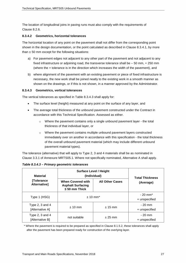
The tolerance (alternative) that will apply to Type 2, 3 and 4 materials shall be as nominated in Clause 3.3.1 of Annexure MRTS05.1. Where not specifically nominated, Alternative A shall apply.
Table 8.3.4.3 – Primary geometric tolerances
Material [Tolerance Alternative]
Surface Level / Height (Individual) Total Thickness
(Average) When Covered with Asphalt Surfacing ≤ 50 mm Thick
All Other Cases
Type 1 (HSG) ± 10 mm* - 20 mm*
+ unspecified
Type 2, 3 and 4 [Alternative A]
± 10 mm ± 15 mm - 20 mm
+ unspecified
Type 2, 3 and 4 [Alternative B]
not suitable ± 25 mm - 20 mm
+ unspecified
* Where the pavement is required to be prepared as specified in Clause 8.1.5.2, these tolerances shall apply after the pavement has been prepared ready for construction of the overlying layer.

Technical Specification, MRTS05 Unbound Pavements
Transport and Main Roads Specifications, November 2018 28
8.3.4.4 Crossfall
For the final (uppermost) layer of unbound pavement to be constructed under the Contract, the crossfall shall not depart from the design crossfall by more than 0.5% absolute. These requirements shall be also be applied to other layers where stated in Clause 3.3.3 of Annexure MRTS05.1.
This crossfall shall be measured:
a) between any two points more than two metres apart excluding where the overall width of a single crossfall is less than two metres wide. For crossfalls less than two metres wide, the measurement shall be made between the extreme edges of the crossfall as shown in the design documentation
b) transverse to the centre line, and
c) within the boundaries of a cross-section element which has a constant crossfall as shown in the design documentation.
8.3.5 Deviation from a straight-edge
The deviation from a three metre long straight-edge placed anywhere on the surface of the final (uppermost) layer of unbound pavement to be constructed under the contract shall be in accordance with the requirements of Table 8.3.5 with due allowance being made for design shape, where relevant. These requirements shall be also be applied to other layers where stated in Clause 3.3.3 of Annexure MRTS05.1.
The tolerance (alternative) that will apply to Type 2, 3 and 4 materials shall be as nominated in Clause 3.3.2 of Annexure MRTS05.1. Where not specifically nominated, Alternative C shall apply.
Table 8.3.5 – Requirements for deviation from a straight-edge
Material [Tolerance Alternative] Maximum Value
Type 1 (HSG) 5 mm
Type 2, 3 and 4 [Alternative C]
5 mm
Type 2, 3 and 4 [Alternative D]
8 mm
8.3.6 Road roughness (surface evenness)
Unless otherwise specified in Clause 3.3.4 of Annexure MRTS05.1, the road roughness of the final (uppermost) layer of an unbound pavement to be constructed under the contract shall be in accordance with the requirements of Table 8.3.6.
Table 8.3.6 – Road roughness requirements
Property Maximum Value
Road Roughness (Rs) (m/km) 2.31

Technical Specification, MRTS05 Unbound Pavements
Transport and Main Roads Specifications, November 2018 29
The Administrator may waive the requirement for roughness testing where the unbound pavement will be overlayed with asphalt or another pavement material within the same contract, and there is a roughness requirement specified elsewhere in the contract for the overlying layer.
Calculation of road roughness should accurately represent the ride quality of the complete pavement. It is generally accepted that the inclusion of other road features within the pavement are likely to reduce ride quality.
In accordance with the test method adopted, these features are required to be noted during roughness testing. The following features are typically allowed to be excluded from the ride quality assessment:
• roundabouts
• railway lines
• bridge joints, and
• inspection pit covers (for example, drainage manholes).
The Contractor should nominate a methodology and provide calculations on ride quality for the Administrators acceptance, showing how each feature has been excluded from the assessment and the subsequent lot structure.
Under no circumstances should pavement features (including joints) or signalised/unsignalised intersections (other than roundabouts) be excluded from the ride quality assessment without the express agreement of the Administrator.
9 Compliance testing
9.1 General
Compliance testing of unbound pavements shall be undertaken on a lot basis in accordance with MRTS01 Introduction to Technical Specifications. A lot shall include only material of the same subtype
For each lot, the Contractor is responsible for performing sufficient tests to ensure that the pavement complies in all regards with the requirements of this Technical Specification. As a minimum the Contractor's testing program shall not be less than that specified in this clause.
The Contractor shall ensure that sufficient, clearly documented construction compliance records are provided to the Administrator to ensure that traceability of unbound pavement materials is provided from their source (for example, quarry face) to the constructed pavement.
The Contractor shall not incorporate materials into the work unless it has demonstrated that the material complies fully with the requirements of this Technical Specification before delivery of the material to site Hold Point 7
Maximum lot sizes, minimum test frequencies and the minimum number of tests required are specified in Appendix A unless otherwise specified in Clause 1.1 of Annexure MRTS05.1.
Where testing frequencies are specified as a number of tests per a quantity, the tests should be representative of the quantity of materials nominated, or part thereof.

Technical Specification, MRTS05 Unbound Pavements
Transport and Main Roads Specifications, November 2018 30
For example, if a frequency of 1 test per 1000 m² is nominated, and a lot includes 2500 m² of that material a minimum of 3 tests would be required.
9.2 Test locations
Unless indicated otherwise in Clause 1.3 of Annexure MRTS05.1, or elsewhere in this Technical Specification samples for material compliance testing shall be taken from the stockpile.
Locations for compliance testing shall be selected by random stratified sampling as specified in Test Method Q050. Representative sampling shall be undertaken as detailed in Test Method Q060. Spot sampling shall be undertaken as detailed in Test Method Q061.
9.3 Maximum lot sizes
The maximum lot sizes for unbound pavements shall be as specified in Table A1 of Appendix A, unless otherwise specified in Clause 1.1 of Annexure MRTS05.1.
9.4 Compliance testing requirements
9.4.1 Unbound pavement materials
Minimum testing frequencies for unbound pavement material source and product testing shall be as specified in Table A2 of Appendix A, unless otherwise specified in Clause 1.2.1 of Annexure MRTS05.1.
9.4.2 Segregation
Minimum testing frequencies for segregation shall be as specified in Table A3 of Appendix A.
The Administrator may direct additional testing of any areas which show visible signs of segregation during construction
9.4.3 Post compaction grading of Type 1 materials
Minimum testing frequencies for post compaction grading of Type 1 (HSG) materials shall be as specified in Table A3 of Appendix A unless otherwise given in Clause 1.2.2 of Annexure MRTS05.1
Breakdown (as well as segregation) of Type 1 material shall be assessed based on its post-compaction grading. The specimen to be tested shall:
a) be sampled from the compacted pavement
b) be sampled using Q061 Spot Sampling of Soils, Crushed Rock and Aggregates, and
c) be sampled at a location adjacent to the location of sampling for the Relative Compaction testing.
9.4.4 Degree of saturation
9.4.4.1 General
Minimum testing frequencies for degree of saturation shall be as specified in Table A3 of Appendix A, unless otherwise specified in Clause 1.2.2 of Annexure MRTS05.1.
The degree of saturation for each lot shall be represented by the maximum characteristic value of the degree of saturation of the individual samples taken from the lot. The characteristic value shall be calculated in accordance with Test Method Q020.

Technical Specification, MRTS05 Unbound Pavements
Transport and Main Roads Specifications, November 2018 31
The degree of saturation result reported for any lot shall be representative of the condition of the lot immediately prior to it being covered by another pavement layer. Should the pavement lot have been subjected to rainfall or moisture ingress in any way since degree of saturation testing was undertaken, the Administrator may direct the Contractor to retest the lot in accordance with Clause 9.4.4.2 to prove conformance.
9.4.4.2 Retesting degree of saturation
Retesting of the Degree of Saturation through measurement of the moisture content only, and without measurement of the compacted density, may be undertaken under the following conditions:
• the compacted density used in the calculation of the Degree of Saturation (retest) shall be that density determined with the initial Degree of Saturation testing, so long as the (retest) moisture content is determined at a location within 1.0 m of the initial test location, and
• sampling for moisture content testing (other than by Q141A), shall be undertaken in accordance with Test Method Q061.
In all other circumstances, retesting of the Degree of Saturation shall include the measurement of both the compacted density, and the moisture content.
If the retested results do not comply with the requirements of this Technical Specification, the Contractor shall dry back and/or reprepare the pavement such that it complies with the requirements of this Technical Specification prior to covering the lot.
9.4.5 Compaction
Minimum testing frequencies for compaction shall be as specified in Table A3 of Appendix A, unless otherwise specified in Clause 1.2.2 of Annexure MRTS05.1.
The compaction standard for each lot shall be represented by the minimum characteristic value of relative compaction. The characteristic value shall be calculated in accordance with Test Method Q020 using the individual relative compaction results reported for each lot.
9.4.6 Proof rolling
Each unbound pavement layer shall be tested for perceptible surface deformation by ‘proof rolling’ the pavement, in the presence of the Administrator Witness Point 2 All areas of unbound pavements shall be ‘proof rolled’, including all trafficked lanes, shoulders and other areas.
Testing shall be in accordance with RMS Test Method T198 unless otherwise approved by the Administrator. Testing for perceptible surface deformation is exempt from the requirement for NATA accreditation or Construction Material Testing (CMT) registration.
In areas where perceptible surface deformation is observed, the Contractor shall remove and replace the affected section, or take other corrective action to the satisfaction of the Administrator. In doing so, the Administrator may require the Contractor to carry out additional compliance testing to ensure that the affected section of pavement complies with Clause 8.2.4 and 8.3.3. No additional payment will be made by the Principal for any such additional testing.

Technical Specification, MRTS05 Unbound Pavements
Transport and Main Roads Specifications, November 2018 32
The proof rolling result reported for any lot shall be representative of the condition of the lot immediately prior to it being covered by another pavement layer. If the pavement lot has been subjected to rainfall or moisture ingress in any way since proof rolling was undertaken, the Administrator may direct the Contractor to retest the lot to prove conformance. If the retested results do not comply with the requirements of this Technical Specification, the Contractor shall dry back and/or reprepare the pavement such that it complies with the requirements of this Technical Specification. No addition payment will be made by the Principal for any such additional efforts.
RMS Test Method T198 provides a method for using either a pneumatic-tyred static roller or a 10,000 L loaded water tanker for proof rolling.
9.4.7 Ball penetration testing
For unbound pavement layers that are to be covered by a sprayed bituminous treatment, the Contractor shall undertake ball penetration testing in accordance with Test Method AG:PT/T251 on the completed layer prior to undertaking the sprayed bituminous treatment.
Minimum testing frequencies for ball penetration testing shall be as specified in Table A3 of Appendix A, unless otherwise specified in Clause 1.2.2 of Annexure MRTS05.1.
In accordance with Test Method AG:PT/T251, ball penetration results shall be reported as both individual and average values.
For the average value to be adopted for lot conformance and seal design purposes, the results must be representative of a homogeneous section of pavement. Any areas represented by excessively low or high individual values should be considered for sub-lotting, and may require additional construction or testing actions before they can be incorporated into the final works. Any such works shall be undertaken by the Contractor at no cost to the Principal.
The ball penetration result reported for any lot shall be representative of the condition of the lot immediately prior to it being covered. If the pavement lot has been subjected to rainfall or moisture ingress in any way since ball penetration testing was undertaken, the Administrator may direct the Contractor to retest the lot to prove conformance. If the retested results do not comply with the requirements of this Technical Specification, the Contractor shall dry back and/or reprepare the pavement such that it complies with the requirements of this Technical Specification. No additional payment will be made by the Principal for any such additional efforts.
9.4.8 Geometrics & deviation from a straight edge
Minimum testing frequencies for geometric tolerances and deviation from a straight edge shall be as specified in Table A4 of Appendix A, unless otherwise specified in Clause 1.2.2 of Annexure MRTS05.1.
Horizontal position, vertical levels, crossfall and layer thickness shall be determined by survey unless otherwise agreed by the Administrator.

Technical Specification, MRTS05 Unbound Pavements
Transport and Main Roads Specifications, November 2018 33
9.4.9 Road roughness (surface evenness)
The road roughness of the final (uppermost) layer of unbound pavement shall be measured by Test Methods Q708B, Q708C or Q708D.
For road roughness testing, a lot shall not be less than 100 m or greater than 500 m in length, unless otherwise approved by the Administrator. Areas of pavement affected by roundabouts, railway lines, bridge joints and inspection pit covers may be excluded from ride quality assessment.
9.5 Compliance testing results
9.5.1 Acceptance of lots
Unless otherwise approved by the Administrator, no unbound pavement layer shall be covered by a subsequent layer of pavement or by a surfacing until Hold Point 8:
a) all testing has been completed
b) the surface finish of the layer complies with the requirements of Clause 8.2.5
c) all test results comply with the requirements of this Technical Specification, or any non-conformances have been submitted, with corrective actions proposed by the Contractor, and accepted by the Administrator, and
d) the layer has been presented to the Administrator for inspection.
10 Supplementary requirements
The requirements of MRTS05 Unbound Pavements are varied by the supplementary requirements specified in Clause 4 of Annexure MRTS05.1.

Technical Specification, MRTS05 Unbound Pavements
Transport and Main Roads Specifications, November 2018 34
Appendix A: Maximum lot sizes and minimum testing frequencies
Table A1 – Maximum lot size requirements
Construction Activity Maximum Lot Size
Supply of unbound pavement materials 5000 tonnes
Construction of unbound pavements A continuous single layer constructed in one day’s production
Road Roughness Testing 500 m
The default testing frequencies provided in this Appendix have been developed for use on typical Transport and Main Roads projects. Where projects warrant specific testing frequencies, these are to be nominated using Annexure MRTS05.1.
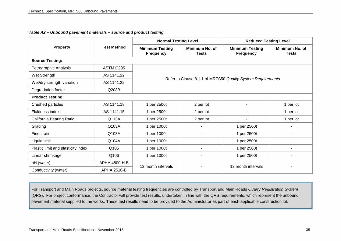
Technical Specification, MRTS05 Unbound Pavements
Transport and Main Roads Specifications, November 2018 35
Table A2 – Unbound pavement materials – source and product testing
Property Test Method Normal Testing Level Reduced Testing Level
Minimum Testing Frequency
Minimum No. of Tests
Minimum Testing Frequency
Minimum No. of Tests
Source Testing:
Petrographic Analysis ASTM C295
Refer to Clause 8.1.1 of MRTS50 Quality System Requirements Wet Strength AS 1141.22
Wet/dry strength variation AS 1141.22
Degradation factor Q208B
Product Testing:
Crushed particles AS 1141.18 1 per 2500t 2 per lot - 1 per lot
Flakiness index AS 1141.15 1 per 2500t 2 per lot - 1 per lot
California Bearing Ratio Q113A 1 per 2500t 2 per lot - 1 per lot
Grading Q103A 1 per 1000t - 1 per 2500t -
Fines ratio Q103A 1 per 1000t - 1 per 2500t -
Liquid limit Q104A 1 per 1000t - 1 per 2500t -
Plastic limit and plasticity index Q105 1 per 1000t - 1 per 2500t -
Linear shrinkage Q106 1 per 1000t - 1 per 2500t -
pH (water) APHA 4500-H B 12 month intervals - 12 month intervals -
Conductivity (water) APHA 2510-B
For Transport and Main Roads projects, source material testing frequencies are controlled by Transport and Main Roads Quarry Registration System (QRS). For project conformance, the Contractor will provide test results, undertaken in line with the QRS requirements, which represent the unbound pavement material supplied to the works. These test results need to be provided to the Administrator as part of each applicable construction lot.
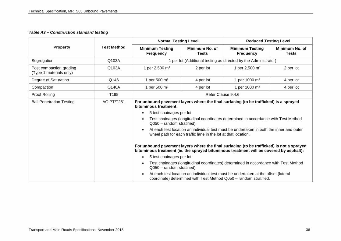
Technical Specification, MRTS05 Unbound Pavements
Transport and Main Roads Specifications, November 2018 36
Table A3 – Construction standard testing
Property Test Method Normal Testing Level Reduced Testing Level
Minimum Testing Frequency
Minimum No. of Tests
Minimum Testing Frequency
Minimum No. of Tests
Segregation Q103A 1 per lot (Additional testing as directed by the Administrator)
Post compaction grading (Type 1 materials only)
Q103A 1 per 2,500 m² 2 per lot 1 per 2,500 m² 2 per lot
Degree of Saturation Q146 1 per 500 m² 4 per lot 1 per 1000 m² 4 per lot
Compaction Q140A 1 per 500 m² 4 per lot 1 per 1000 m² 4 per lot
Proof Rolling T198 Refer Clause 9.4.6
Ball Penetration Testing AG:PT/T251 For unbound pavement layers where the final surfacing (to be trafficked) is a sprayed bituminous treatment:
• 5 test chainages per lot • Test chainages (longitudinal coordinates determined in accordance with Test Method
Q050 – random stratified) • At each test location an individual test must be undertaken in both the inner and outer
wheel path for each traffic lane in the lot at that location. For unbound pavement layers where the final surfacing (to be trafficked) is not a sprayed bituminous treatment (ie. the sprayed bituminous treatment will be covered by asphalt):
• 5 test chainages per lot • Test chainages (longitudinal coordinates) determined in accordance with Test Method
Q050 – random stratified) • At each test location an individual test must be undertaken at the offset (lateral
coordinate) determined with Test Method Q050 – random stratified.
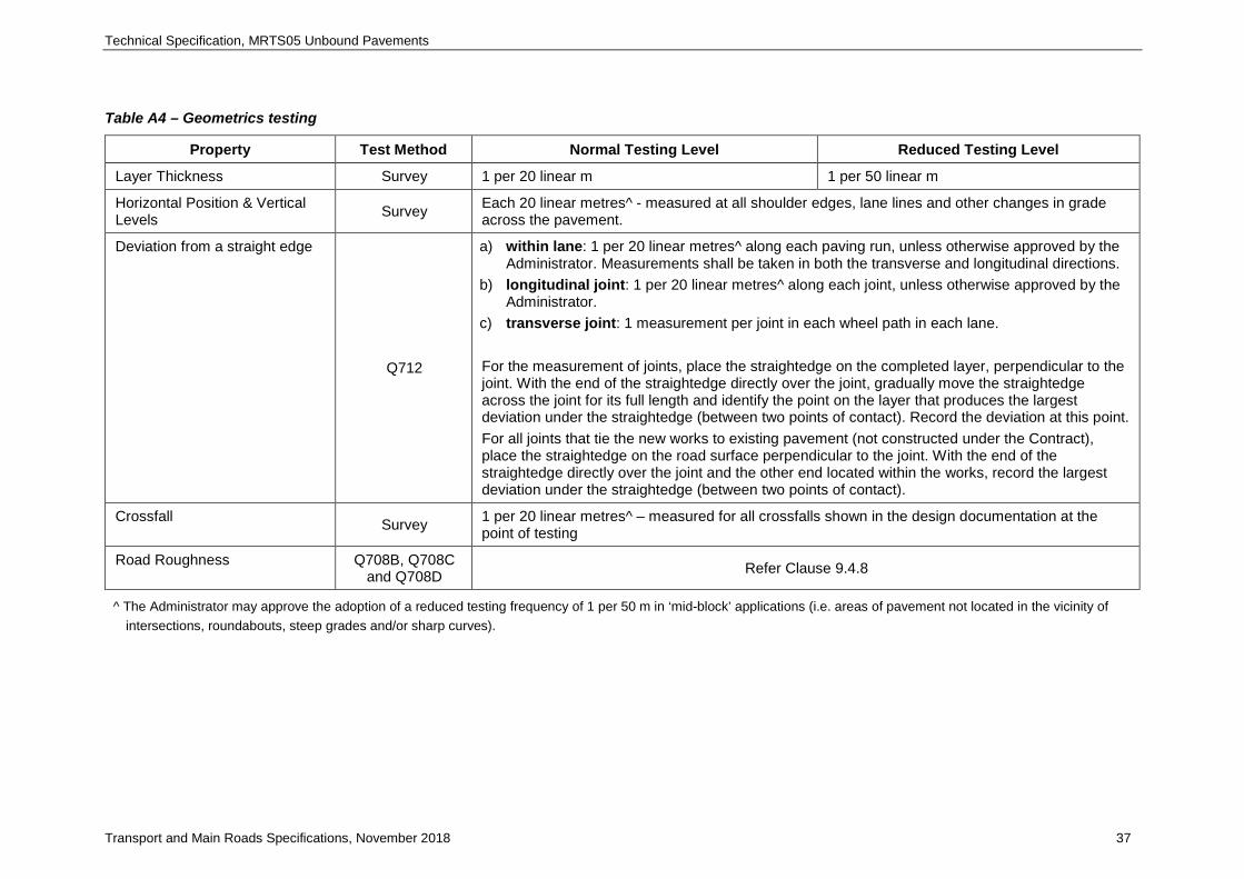
Technical Specification, MRTS05 Unbound Pavements
Transport and Main Roads Specifications, November 2018 37
Table A4 – Geometrics testing
Property Test Method Normal Testing Level Reduced Testing Level
Layer Thickness Survey 1 per 20 linear m 1 per 50 linear m
Horizontal Position & Vertical Levels Survey Each 20 linear metres^ - measured at all shoulder edges, lane lines and other changes in grade
across the pavement.
Deviation from a straight edge
Q712
a) within lane: 1 per 20 linear metres^ along each paving run, unless otherwise approved by the Administrator. Measurements shall be taken in both the transverse and longitudinal directions.
b) longitudinal joint: 1 per 20 linear metres^ along each joint, unless otherwise approved by the Administrator.
c) transverse joint: 1 measurement per joint in each wheel path in each lane. For the measurement of joints, place the straightedge on the completed layer, perpendicular to the joint. With the end of the straightedge directly over the joint, gradually move the straightedge across the joint for its full length and identify the point on the layer that produces the largest deviation under the straightedge (between two points of contact). Record the deviation at this point. For all joints that tie the new works to existing pavement (not constructed under the Contract), place the straightedge on the road surface perpendicular to the joint. With the end of the straightedge directly over the joint and the other end located within the works, record the largest deviation under the straightedge (between two points of contact).
Crossfall Survey 1 per 20 linear metres^ – measured for all crossfalls shown in the design documentation at the point of testing
Road Roughness Q708B, Q708C and Q708D Refer Clause 9.4.8
^ The Administrator may approve the adoption of a reduced testing frequency of 1 per 50 m in ‘mid-block’ applications (i.e. areas of pavement not located in the vicinity of intersections, roundabouts, steep grades and/or sharp curves).