mppt - maximum power point tracking
DESCRIPTION
MPPT - Maximum Power Point Tracking.pdfTRANSCRIPT
mppt: a maximum power point trackingphotovoltaic system.
INTRODUCTION
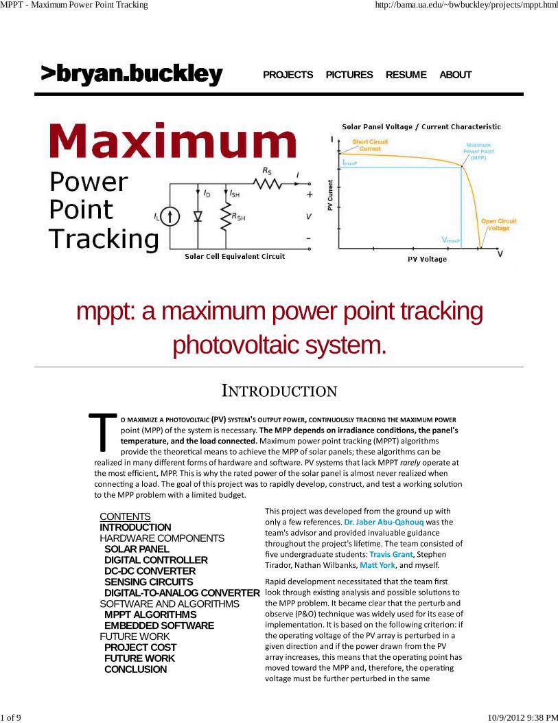
O MAXIMIZE A PHOTOVOLTAIC (PV) SYSTEM'S OUTPUT POWER, CONTINUOUSLY TRACKING THE MAXIMUM POWER
point (MPP) of the system is necessary. The MPP depends on irradiance condi&ons, the panel's
temperature, and the load connected. Maximum power point tracking (MPPT) algorithms
provide the theore�cal means to achieve the MPP of solar panels; these algorithms can be
realized in many different forms of hardware and so#ware. PV systems that lack MPPT rarely operate at
the most efficient, MPP. This is why the rated power of the solar panel is almost never realized when
connec�ng a load. The goal of this project was to rapidly develop, construct, and test a working solu�on
to the MPP problem with a limited budget.
This project was developed from the ground up with
only a few references. was the
team's advisor and provided invaluable guidance
throughout the project's life�me. The team consisted of
five undergraduate students: , Stephen
Tirador, Nathan Wilbanks, , and myself.
Rapid development necessitated that the team first
look through exis�ng analysis and possible solu�ons to
the MPP problem. It became clear that the perturb and
observe (P&O) technique was widely used for its ease of
implementa�on. It is based on the following criterion: if
the opera�ng voltage of the PV array is perturbed in a
given direc�on and if the power drawn from the PV
array increases, this means that the opera�ng point has
moved toward the MPP and, therefore, the opera�ng
voltage must be further perturbed in the same
PROJECTS PICTURES RESUME ABOUT
CONTENTS
HARDWARE COMPONENTS SOFTWARE AND ALGORITHMS FUTURE WORK
INTRODUCTION
SOLAR PANELDIGITAL CONTROLLERDC-DC CONVERTERSENSING CIRCUITSDIGITAL-TO-ANALOG CONVERTER
MPPT ALGORITHMSEMBEDDED SOFTWARE
PROJECT COSTFUTURE WORKCONCLUSION
Dr. Jaber Abu‐Qahouq
Travis Grant
Ma3 York
MPPT - Maximum Power Point Tracking http://bama.ua.edu/~bwbuckley/projects/mppt.html
1 of 9 10/9/2012 9:38 PM
direc�on. Otherwise, if the power drawn from the PV array decreases, the opera�ng point has moved
away from the MPP and, therefore, the direc�on of the opera�ng voltage perturba�on must be
reversed.
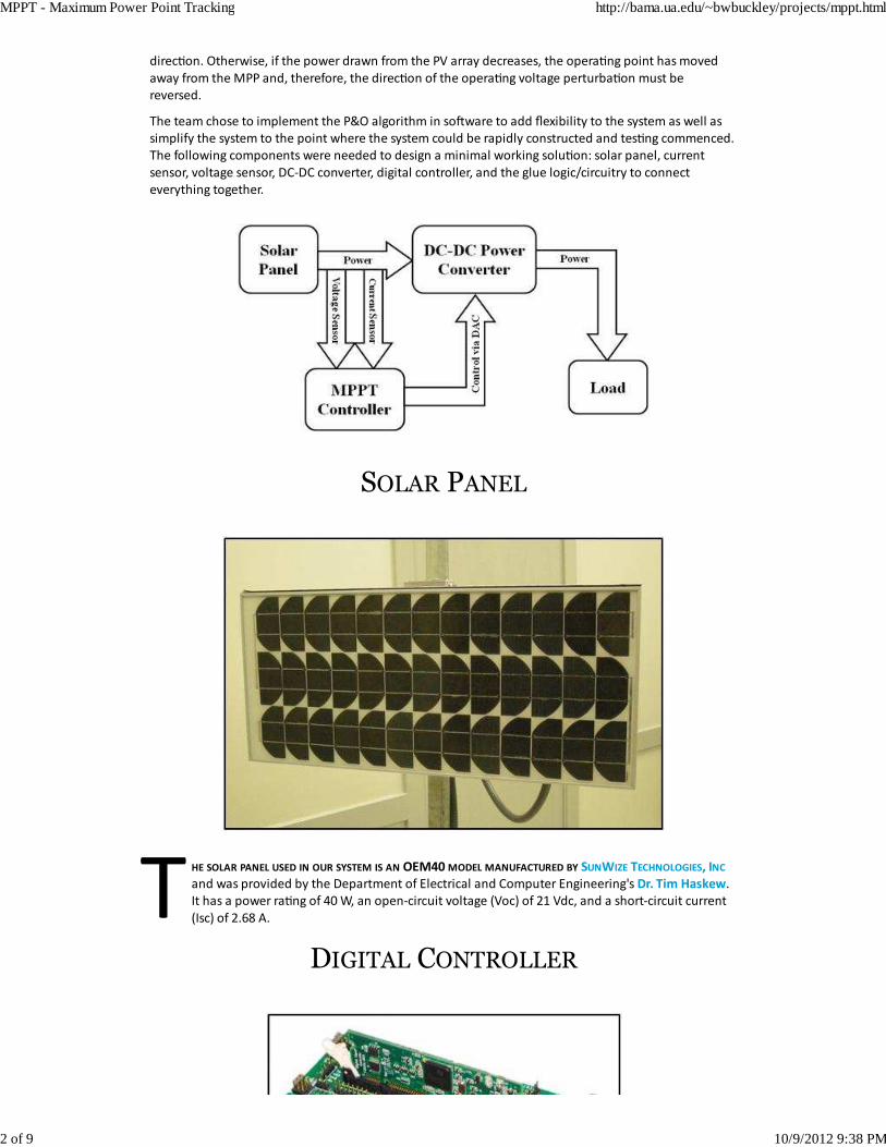
The team chose to implement the P&O algorithm in so#ware to add flexibility to the system as well as
simplify the system to the point where the system could be rapidly constructed and tes�ng commenced.
The following components were needed to design a minimal working solu�on: solar panel, current
sensor, voltage sensor, DC‐DC converter, digital controller, and the glue logic/circuitry to connect
everything together.
SOLAR PANEL
HE SOLAR PANEL USED IN OUR SYSTEM IS AN OEM40 MODEL MANUFACTURED BY
and was provided by the Department of Electrical and Computer Engineering's .
It has a power ra�ng of 40 W, an open‐circuit voltage (Voc) of 21 Vdc, and a short‐circuit current
(Isc) of 2.68 A.
DIGITAL CONTROLLER
SUNWIZE TECHNOLOGIES, INC
Dr. Tim Haskew
MPPT - Maximum Power Point Tracking http://bama.ua.edu/~bwbuckley/projects/mppt.html
2 of 9 10/9/2012 9:38 PM
HE MICROCONTROLLER PROVIDES THE CONTROL IN OUR SYSTEM. THE CHOICE OF MICROCONTROLLER FOR THE
system dictates much of the cost, performance, and flexibility of the en�re system. Taking into
considera�on the project's constraints, the Texas Instruments model digital
signal controller (DSC) was chosen. The single‐chip C2000 family of microcontrollers is targeted
toward real‐�me control applica�ons thanks to powerful, high performance integrated peripherals. The
core is "math‐op�mized" and gives designers the means to improve system efficiency, reliability, and
flexibility when the applica�on requires complex algorithms. It features:
The C2000's development tools are very useable and help minimize development �me. So#ware for the
controller can be developed, deployed, and tested with ease thanks to the provided, easy to use IDE
featuring a C/C++ assembler/compiler/linker in addi�on to a powerful debugger and seamless device
programmer.
DC-DC CONVERTER
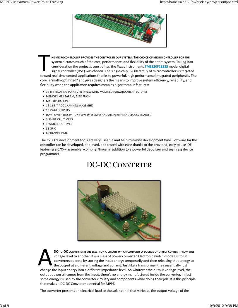
DC‐TO‐DC CONVERTER IS AN ELECTRONIC CIRCUIT WHICH CONVERTS A SOURCE OF DIRECT CURRENT FROM ONE
voltage level to another. It is a class of power converter. Electronic switch‐mode DC to DC
converters operate by storing the input energy temporarily and then releasing that energy to
the output at a different voltage and current. Just like a transformer, they essen�ally just
change the input energy into a different impedance level. So whatever the output voltage level, the
output power all comes from the input; there's no energy manufactured inside the converter. In fact
some energy is used by the converter circuitry and components while doing their job. It is this principle
that makes a DC‐DC Converter essen�al for MPPT.
The converter presents an electrical load to the solar panel that varies as the output voltage of the
TMS320F28335
32‐BIT FLOATING POINT CPU (<=150 MHZ, MODIFIED HARVARD ARCHITECTURE)
MEMORY: 68K SARAM, 512K FLASH
MAC OPERATIONS
16 12‐BIT ADC CHANNELS (<=25MHZ)
18 PWM OUTPUTS
LOW POWER DISSIPATION (<1W @ 150MHZ AND ALL PERIPHERAL CLOCKS ENABLED)
3 32‐BIT CPU TIMERS
1 WATCHDOG TIMER
88 GPIO
6 CHANNEL DMA
MPPT - Maximum Power Point Tracking http://bama.ua.edu/~bwbuckley/projects/mppt.html
3 of 9 10/9/2012 9:38 PM
converter varies. This load varia�on in turn causes a change in the opera�ng point (current and voltage
characteris�cs) of the panel. Thus by intelligently controlling the opera�on of the DC‐DC converter, the
power output of the panel can be intelligently controlled and made to output the maximum possible.
The DC‐DC power converter used in our system is a Micro 24 Vout, 100 W V28C24C100BL model
manufactured by . The input voltage range of the converter is 9‐36 Vdc. Because the voltage
provided by the solar panel (which serves as the input voltage to the converter) can drop below the
converter's 9 Vdc minimum and thus cause the converter to shut down, our MPPT system is only
opera�onal when the voltage provided by the solar panel is greater than or equal to 9 Vdc. The output
voltage of the converter can be varied between 10% and 110% of its nominal 24 Vdc output (i.e. 2.4‐26.4
Vdc) via a reference input voltage at the SC pin with respect to the ‐OUT pin between 0.123‐1.353 Vdc.
The converter has the capability of func�oning in isolated or non‐isolated mode depending on whether
the grounds of the converter (‐IN and ‐OUT) are separate or connected together, respec�vely.
SENSING CIRCUITS
VOLTAGE SENSOR
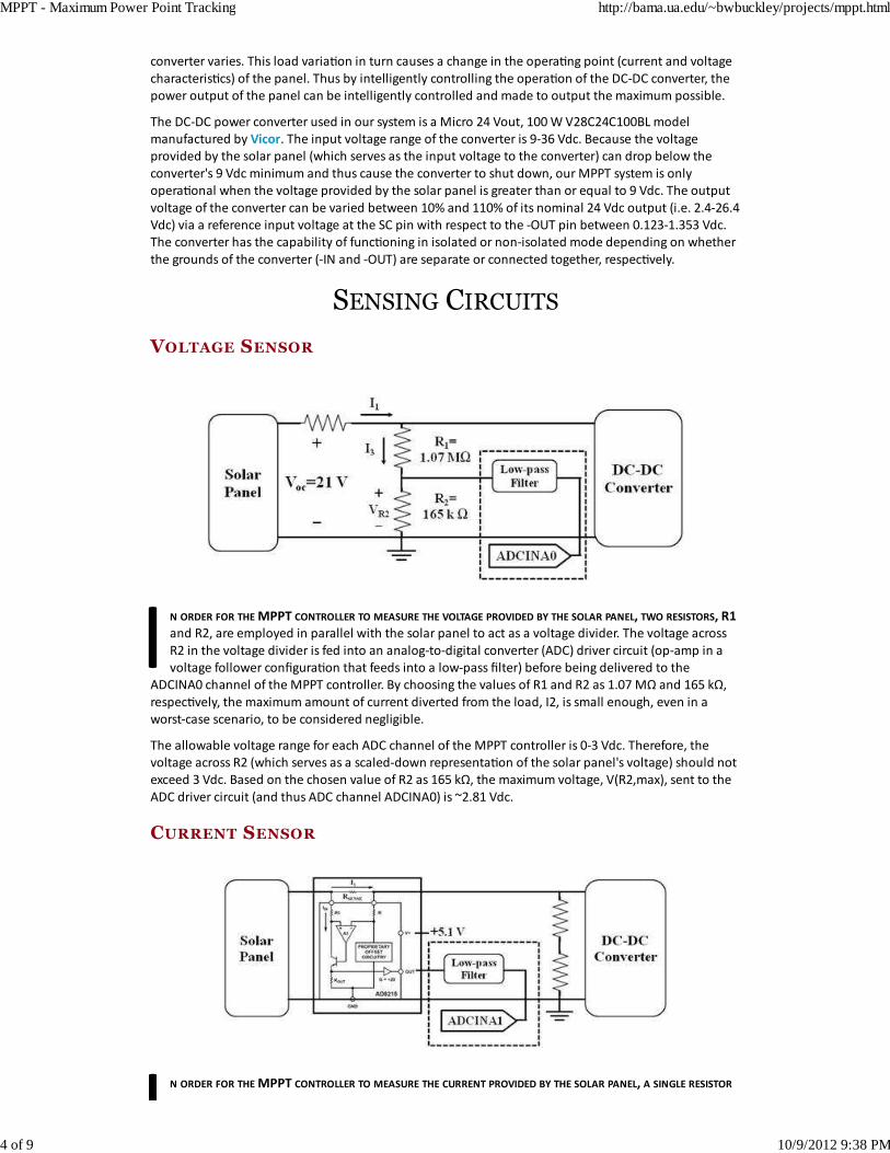
N ORDER FOR THE MPPT CONTROLLER TO MEASURE THE VOLTAGE PROVIDED BY THE SOLAR PANEL, TWO RESISTORS, R1
and R2, are employed in parallel with the solar panel to act as a voltage divider. The voltage across
R2 in the voltage divider is fed into an analog‐to‐digital converter (ADC) driver circuit (op‐amp in a
voltage follower configura�on that feeds into a low‐pass filter) before being delivered to the
ADCINA0 channel of the MPPT controller. By choosing the values of R1 and R2 as 1.07 MΩ and 165 kΩ,
respec�vely, the maximum amount of current diverted from the load, I2, is small enough, even in a
worst‐case scenario, to be considered negligible.
The allowable voltage range for each ADC channel of the MPPT controller is 0‐3 Vdc. Therefore, the
voltage across R2 (which serves as a scaled‐down representa�on of the solar panel's voltage) should not
exceed 3 Vdc. Based on the chosen value of R2 as 165 kΩ, the maximum voltage, V(R2,max), sent to the
ADC driver circuit (and thus ADC channel ADCINA0) is ~2.81 Vdc.
CURRENT SENSOR
N ORDER FOR THE MPPT CONTROLLER TO MEASURE THE CURRENT PROVIDED BY THE SOLAR PANEL, A SINGLE RESISTOR
Vicor
MPPT - Maximum Power Point Tracking http://bama.ua.edu/~bwbuckley/projects/mppt.html
4 of 9 10/9/2012 9:38 PM
(Rsense) is placed in series between the solar panel and the DC‐DC converter. The voltage across Rsense
is fed into an AD8215 current sensor manufactured by whose output voltage is then fed
into an ADC driver circuit (op‐amp in a voltage follower configura�on that feeds into a low‐pass filter)
before being delivered to the ADCINA1 channel of the MPPT controller. By choosing the value of Rsense
as 51 mΩ, the maximum voltage drop across Rsense, VRsense, is small enough, even in a worst‐case
scenario, to be considered negligible.
As stated previously, the allowable voltage range for each ADC channel of the MPPT controller is 0‐3
Vdc. Therefore, the output voltage of the AD8215 current sensor (which serves as an equivalent voltage
representa�on of the solar panel's current) should not exceed 3 Vdc. Based on the chosen value of
Rsense as 51 mΩ, the maximum voltage, Vout, sent to the ADC driver circuit (and thus ADC channel
ADCINA1) is ~2.73 Vdc.
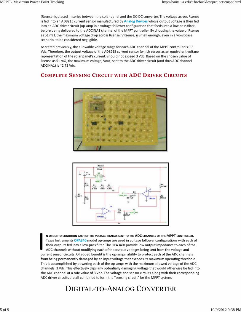
COMPLETE SENSING CIRCUIT WITH ADC DRIVER CIRCUITS
N ORDER TO CONDITION EACH OF THE VOLTAGE SIGNALS SENT TO THE ADC CHANNELS OF THE MPPT CONTROLLER,
Texas Instruments model op‐amps are used in voltage follower configura�ons with each of
their outputs fed into a low‐pass filter. The OPA340s provide low output impedance to each of the
ADC channels without modifying each of the output voltages being sent from the voltage and
current sensor circuits. Of added benefit is the op‐amps' ability to protect each of the ADC channels
from being permanently damaged by an input voltage that exceeds its maximum opera�ng threshold.
This is accomplished by powering each of the op‐amps with the maximum allowed voltage of the ADC
channels: 3 Vdc. This effec�vely clips any poten�ally damaging voltage that would otherwise be fed into
the ADC channel at a safe value of 3 Vdc. The voltage and sensor circuits along with their corresponding
ADC driver circuits are all combined to form the "sensing circuit" for the MPPT system.
DIGITAL-TO-ANALOG CONVERTER
Analog Devices
OPA340
MPPT - Maximum Power Point Tracking http://bama.ua.edu/~bwbuckley/projects/mppt.html
5 of 9 10/9/2012 9:38 PM
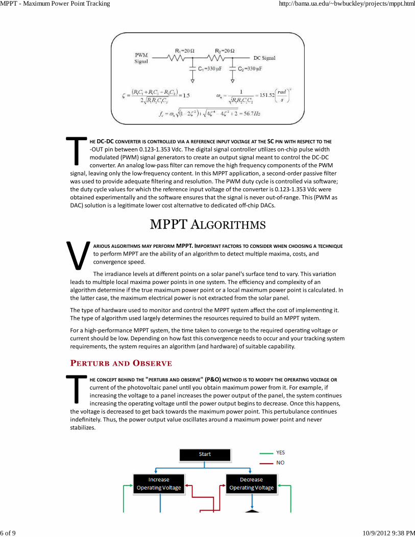
HE DC‐DC CONVERTER IS CONTROLLED VIA A REFERENCE INPUT VOLTAGE AT THE SC PIN WITH RESPECT TO THE
‐OUT pin between 0.123‐1.353 Vdc. The digital signal controller u�lizes on‐chip pulse width
modulated (PWM) signal generators to create an output signal meant to control the DC‐DC
converter. An analog low‐pass filter can remove the high frequency components of the PWM
signal, leaving only the low‐frequency content. In this MPPT applica�on, a second‐order passive filter
was used to provide adequate filtering and resolu�on. The PWM duty cycle is controlled via so#ware;
the duty cycle values for which the reference input voltage of the converter is 0.123‐1.353 Vdc were
obtained experimentally and the so#ware ensures that the signal is never out‐of‐range. This (PWM as
DAC) solu�on is a legi�mate lower cost alterna�ve to dedicated off‐chip DACs.
MPPT ALGORITHMS
ARIOUS ALGORITHMS MAY PERFORM MPPT. IMPORTANT FACTORS TO CONSIDER WHEN CHOOSING A TECHNIQUE
to perform MPPT are the ability of an algorithm to detect mul�ple maxima, costs, and
convergence speed.
The irradiance levels at different points on a solar panel's surface tend to vary. This varia�on
leads to mul�ple local maxima power points in one system. The efficiency and complexity of an
algorithm determine if the true maximum power point or a local maximum power point is calculated. In
the laVer case, the maximum electrical power is not extracted from the solar panel.
The type of hardware used to monitor and control the MPPT system affect the cost of implemen�ng it.
The type of algorithm used largely determines the resources required to build an MPPT system.
For a high‐performance MPPT system, the �me taken to converge to the required opera�ng voltage or
current should be low. Depending on how fast this convergence needs to occur and your tracking system
requirements, the system requires an algorithm (and hardware) of suitable capability.
PERTURB AND OBSERVE
HE CONCEPT BEHIND THE "PERTURB AND OBSERVE" (P&O) METHOD IS TO MODIFY THE OPERATING VOLTAGE OR
current of the photovoltaic panel un�l you obtain maximum power from it. For example, if
increasing the voltage to a panel increases the power output of the panel, the system con�nues
increasing the opera�ng voltage un�l the power output begins to decrease. Once this happens,
the voltage is decreased to get back towards the maximum power point. This pertubulance con�nues
indefinitely. Thus, the power output value oscillates around a maximum power point and never
stabilizes.
MPPT - Maximum Power Point Tracking http://bama.ua.edu/~bwbuckley/projects/mppt.html
6 of 9 10/9/2012 9:38 PM
P&O is simple to implement and thus can be implemented quickly. The major drawbacks of the P&O
method are that the power obtained oscillates around the maximum power point in steady state
opera�on, it can track in the wrong direc�on under rapidly varying irradiance levels and load levels, and
the step size (the magnitude of the change in the opera�ng voltage) determines both the speed of
convergence to the MPP and the range of oscilla�on around the MPP at steady state opera�on.
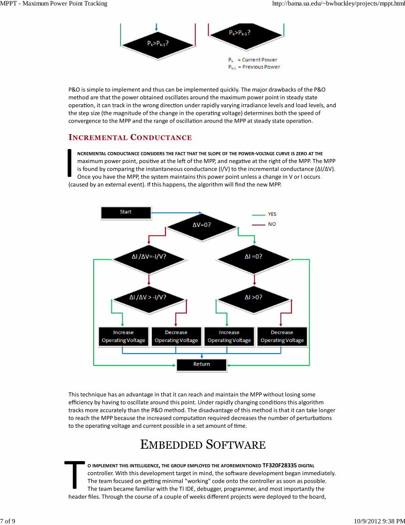
INCREMENTAL CONDUCTANCE
NCREMENTAL CONDUCTANCE CONSIDERS THE FACT THAT THE SLOPE OF THE POWER‐VOLTAGE CURVE IS ZERO AT THE
maximum power point, posi�ve at the le# of the MPP, and nega�ve at the right of the MPP. The MPP
is found by comparing the instantaneous conductance (I/V) to the incremental conductance (ΔI/ΔV).
Once you have the MPP, the system maintains this power point unless a change in V or I occurs
(caused by an external event). If this happens, the algorithm will find the new MPP.
This technique has an advantage in that it can reach and maintain the MPP without losing some
efficiency by having to oscillate around this point. Under rapidly changing condi�ons this algorithm
tracks more accurately than the P&O method. The disadvantage of this method is that it can take longer
to reach the MPP because the increased computa�on required decreases the number of perturba�ons
to the opera�ng voltage and current possible in a set amount of �me.
EMBEDDED SOFTWARE
O IMPLEMENT THIS INTELLIGENCE, THE GROUP EMPLOYED THE AFOREMENTIONED TF320F28335 DIGITAL
controller. With this development target in mind, the so#ware development began immediately.
The team focused on geXng minimal "working" code onto the controller as soon as possible.
The team became familiar with the TI IDE, debugger, programmer, and most importantly the
header files. Through the course of a couple of weeks different projects were deployed to the board,
MPPT - Maximum Power Point Tracking http://bama.ua.edu/~bwbuckley/projects/mppt.html
7 of 9 10/9/2012 9:38 PM
ranging from flashing an LED to running programs from the flash memory. Each peripheral to be used in
the MPPT project was inves�gated and played with in these first few weeks. Most significantly, unit tests
for the PWM and the ADC (using DMA) were developed. Each unit test was built with pre‐defined
pass/fail criteria.
For the PWM unit test, the duty cycle of the PWM would be automa�cally, con�nuously varied through
the en�re opera�ng range of the final MPPT project as defined by the DC‐DC converter control pin
specs. The test would pass if the PWM duty never exceeded or fell under the defined upper and lower
limits and if the PWM duty was con�nuously increasing or decreasing. This test could run without
interfacing with the DC‐DC converter; an oscilloscope was hooked into the PWM pins of the controller
and the test behavior was observed.
For the ADC unit test, the result of an ADC conversion would be stored in a monitored variable. The
reference analog signal was varied through a range of values and the variables value was recorded for
each analog value. These recorded values were compared to calculated, expected values to verify
opera�on.
Once the team was very comfortable working with the C2000, work began on a custom MPPT algorithm
based on the P&O algorithm from before. This algorithm was aVempted first since it was the simplest
solu�on requiring the least amount of effort while s�ll fulfilling requirements. The simplicity of the
algorithm could also afford the team more �me to integrate the hardware and so#ware near the end of
development if necessary. This system and algorithm does not require a scheduler; if the controller
needed to be more reac�ve to more inputs (tracking the MPP of more solar panels) then a scheduling
method would likely be necessary to ensure a quick response to all inputs and efficient u�liza�on of the
processor.
This system is designed to run for a long �me; the so#ware is single purpose and loops forever. Each
loop is an itera�on of the P&O algorithm described earlier. Each itera�on starts by seXng a variable to
the calculated amount of power being supplied by the panel (current and voltage values known from
ADC). The program then switches on whether the power point is increasing or decreasing in voltage.
Inside each case the itera�on's power value is compared to the previous itera�on's and the duty of the
PWM is either increased or decreased to move closer to the MPP; if the PWM duty is increased, the
voltage will be increasing, if the PWM duty is decreased, the voltage will be decreasing. Before repea�ng
the loop, the previous itera�on's power variable is set to the current itera�on's. Pseudo code for this
behavior is below.
next_pwr = calcPwr(adc_voltage, adc_current);
switch(voltage_direction){
case PV_RIGHT :
if (next_pwr > prev_pwr){incDuty();}
else if (next_pwr <= prev_pwr){
decDuty();
voltage_direction = PV_LEFT;}
break;
case PV_LEFT :
if(next_pwr >= prev_pwr){decDuty();}
else if (next_pwr < prev_pwr){
incDuty();
voltage_direction = PV_RIGHT;}
break;
}
prev_pwr = next_pwr;
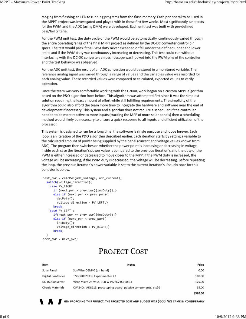
PROJECT COST
Item Notes Price
Solar Panel SunWize OEM40 (on hand) 0.00
Digital Controller TMS320F28335 Experimenter Kit 110.00
DC‐DC Converter Vicor Micro 24 Vout, 100 W (V28C24C100BL) 175.00
Circuit Materials OPA340s, AD8215, prototyping board, passive components, etc… 35.00
$320.00
HEN PROPOSING THIS PROJECT, THE PROJECTED COST AND BUDGET WAS $500. WE CAME IN CONSIDERABLY
MPPT - Maximum Power Point Tracking http://bama.ua.edu/~bwbuckley/projects/mppt.html
8 of 9 10/9/2012 9:38 PM
under budget primarily thanks to having a solar panel on hand. A solar panel could have been
constructed from solar cells available at $.5/WaV, or about $20, though construc�on materials would
add more cost. Our simple system (40W panel and P&O algorithm) could have been constructed with a
very simple microcontroller and a less capable DC‐DC converter, bringing the cost down to close to $150.
However, with a cheaper microcontroller, the math opera�ons take longer to evaluate. The incremental
conductance algorithm is more math intensive and has more control flow for one itera�on; a cheap
microcontroller will not offer the same performance as the C2000. Also, the C2000 has enough
performance capabili�es and ADC and PWM channels to calculate the MPPT of many different solar
panels simultaneously.
FUTURE WORK
HE SCOPE OF THIS PROJECT WAS SIMPLY TO CREATE A WORKING PROTOTYPE OF A MPPT SYSTEM. THIS SYSTEM
successfully uses the simple P&O algorithm to reach the MPP. The addi�onal resources (labor)
needed to implement the more complex incremental conductance algorithm is quite modest.
Reaching a stable, true MPP at steady state instead of oscilla�ng around this point would
improve the system's efficiency and increase reliability. Thus implemen�ng the incremental
conductance algorithm is a good choice in con�nuing this project.
Another extension of this project would be to directly power the microcontroller and other circuits from
the solar panel instead of from a power supply. Or to incorporate a power supply into the system that
draws energy from the solar panel or an energy storage element that is in turn charged by the solar
panel. This extension would allow the system to be deployed to remote loca�ons.
Yet another more useful system would be one that could directly power a DC or AC load. An addi�onal
DC‐DC converter would be needed to supply a regulated DC signal. An inverter is needed to supply an
AC signal. If the AC signal is meant to connect to the grid, it is necessary to synchronize the frequency of
the signal with that of the grid in addi�on to limi�ng the voltage to no higher than the grid voltage.
This digital controller would allow us to add these features to our system with rela�ve ease thanks to its
high performance and many peripherals.
UPDATE: Thanks to the success of this project and the large amount of documenta�on le# behind, two
new teams will be working on extending different parts of this project for next year.
CONCLUSION
RENEWABLE ENERGY SYSTEM, LIKE THE ONE IMPLEMENTED HERE, IS SUITABLE FOR RESIDENTIAL AND/OR
industrial applica�ons. Such a system would typically provide a regulated AC output voltage
that may also track the input mains u�lity voltage in phase and amplitude at hundreds to
thousands of waVs. Thus a system such as this can be deployed easily with liVle concern about
adap�ng a home or business's electrical wiring to take advantage of solar energy. Many areas allow
surplus energy generated by systems such as this to be sold to the u�lity grid in a policy known as "net
metering." But for this project, these features were out of scope.
MPPT - Maximum Power Point Tracking http://bama.ua.edu/~bwbuckley/projects/mppt.html
9 of 9 10/9/2012 9:38 PM