mpls oam tutorial final
TRANSCRIPT

Agenda• Introduction
• Terms and Terminology
• An Introduction to Tools
• Introduction to MPLS
• MPLS TP 101
• Troubleshooting MPLS
• MPLS OAM
• LSP Ping
• ECMP troubleshooting
• BFD for MPLS
• Tools GaloreJune 3-6, 2012 2NANOG55
What is OAM
• Means different things to different people and
organizations.
• Worst, some times it means different things to
different people within the same organization
• IETF standardized the meaning of OAM within the
IETFIETF
– June 2011, RFC 6291
June 3-6, 2012 3NANOG55
IETF definition of OAM
• Operations: Operational activities to keep
network up and running. E.g. Monitoring, finding
faults
• Administration: Involves keeping track of
network resources. E.g. Bookkeeping, (available ports, network resources. E.g. Bookkeeping, (available ports,
BW)
• Maintenance: Involves repair and upgrades. E.g. Software upgrades, configurations, corrective and
preventive measures.
June 3-6, 2012 4NANOG55
Scope of the Tutorial
• Today’s presentation mainly focus on IETF
defined Operations aspects of MPLS OAM.
• Various OAM operations and techniques are
presented for MPLS networks
June 3-6, 2012 5NANOG55
Agenda
• Introduction
• Terms and Terminology
• An Introduction to Tools
• Introduction to MPLS
• MPLS TP 101• MPLS TP 101
• Troubleshooting MPLS
• MPLS OAM
• LSP Ping
• ECMP troubleshooting
• BFD for MPLS
• Tools GaloreJune 3-6, 2012 6NANOG55
Important Terminologies
• Before we dive deeper, it is important to understand some of the terminologies and their meanings
• What are they ?
– Various organizations (IEEE, ITUT, IETF) all have their versionversion
– We will discuss here selected set of definitions from RFC 5860, RFC 6371 and draft-ietf-opsawg-oam-overview-05
• Good understanding of these Terminologies will help us to appreciate modern OAM protocols better.
June 3-6, 2012 7NANOG55
Important Terminologies• Maintenance Point (MP)
– Is a functional entity that is defined within a node that either
initiate or react to a OAM message
• Maintenance Entity (ME)
– Point to Point relationship between two MP
– In MPLS this is LSP, In BFD this is session
• Maintenance Point can be either MEP or MIP
– Maintenance End Point (MEP)
• Can either initiate or react to OAM Messages
• MEP are the two end points of the ME
– Maintenance Intermediate Point (MIP)
• Is an intermediate MP between two MEP
• It can only respond to OAM messagesJune 3-6, 2012 8NANOG55
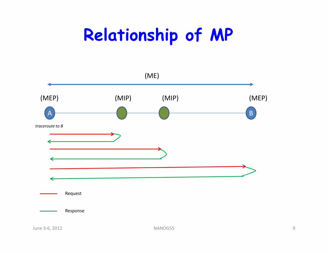
Relationship of MP
A B
(ME)
(MEP) (MEP)(MIP) (MIP)
traceroute to Btraceroute to B
Request
Response
June 3-6, 2012 9NANOG55
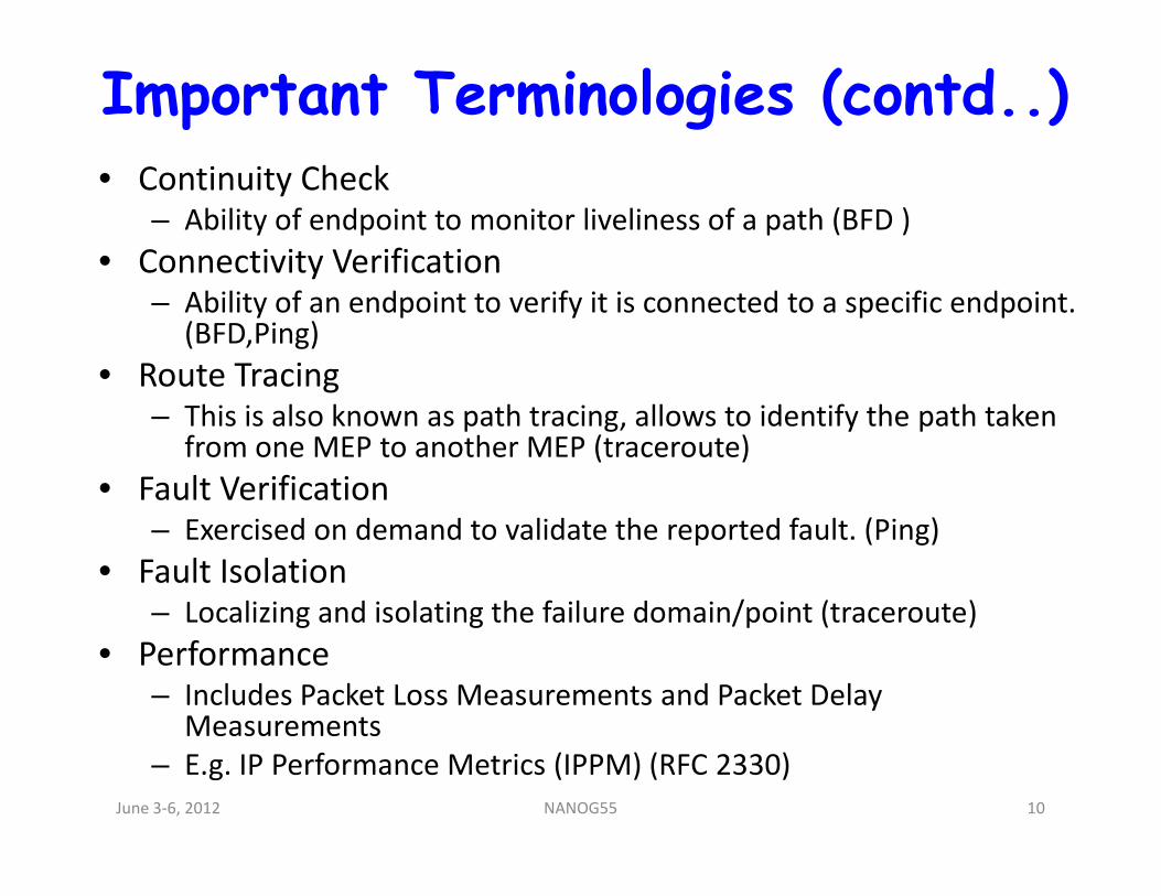
Important Terminologies (contd..)• Continuity Check
– Ability of endpoint to monitor liveliness of a path (BFD )
• Connectivity Verification– Ability of an endpoint to verify it is connected to a specific endpoint.
(BFD,Ping)
• Route Tracing– This is also known as path tracing, allows to identify the path taken
from one MEP to another MEP (traceroute)from one MEP to another MEP (traceroute)
• Fault Verification– Exercised on demand to validate the reported fault. (Ping)
• Fault Isolation– Localizing and isolating the failure domain/point (traceroute)
• Performance – Includes Packet Loss Measurements and Packet Delay
Measurements
– E.g. IP Performance Metrics (IPPM) (RFC 2330)
June 3-6, 2012 10NANOG55
Agenda• Introduction
• Terms and Terminology
• An Introduction to Tools
• Introduction to MPLS
• MPLS TP 101
• Troubleshooting MPLS
• MPLS OAM
• LSP Ping
• ECMP troubleshooting
• BFD for MPLS
• Tools GaloreJune 3-6, 2012 11NANOG55
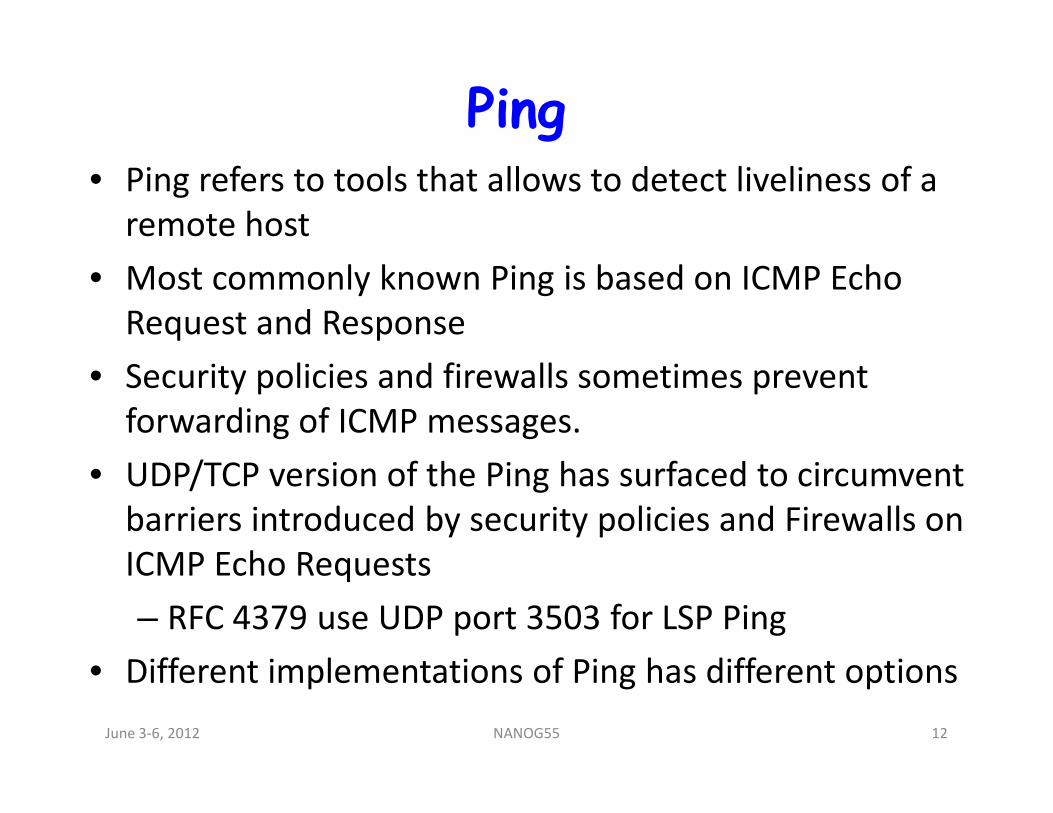
Ping• Ping refers to tools that allows to detect liveliness of a
remote host
• Most commonly known Ping is based on ICMP Echo
Request and Response
• Security policies and firewalls sometimes prevent
forwarding of ICMP messages.forwarding of ICMP messages.
• UDP/TCP version of the Ping has surfaced to circumvent
barriers introduced by security policies and Firewalls on
ICMP Echo Requests
– RFC 4379 use UDP port 3503 for LSP Ping
• Different implementations of Ping has different options
June 3-6, 2012 12NANOG55
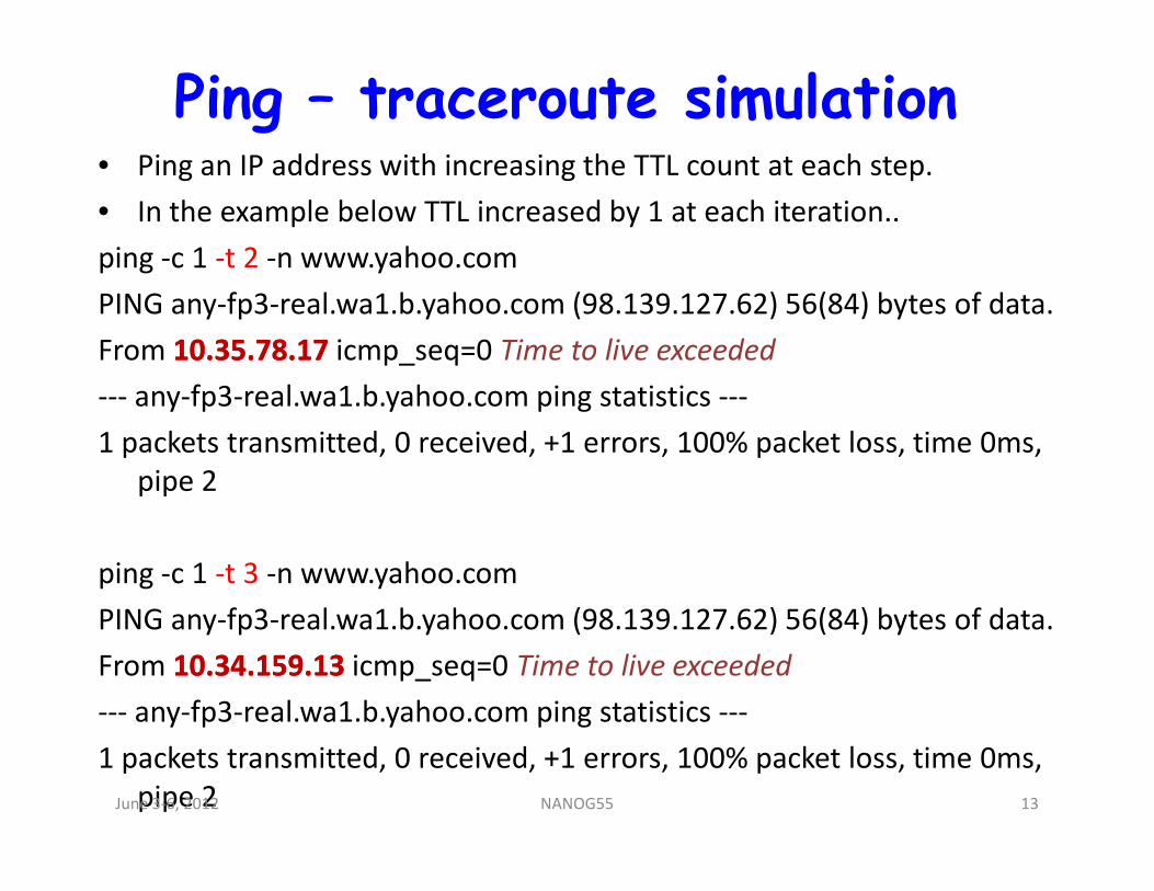
Ping – traceroute simulation• Ping an IP address with increasing the TTL count at each step.
• In the example below TTL increased by 1 at each iteration..
ping -c 1 -t 2 -n www.yahoo.com
PING any-fp3-real.wa1.b.yahoo.com (98.139.127.62) 56(84) bytes of data.
From 10.35.78.1710.35.78.17 icmp_seq=0 Time to live exceeded
--- any-fp3-real.wa1.b.yahoo.com ping statistics ---
1 packets transmitted, 0 received, +1 errors, 100% packet loss, time 0ms, 1 packets transmitted, 0 received, +1 errors, 100% packet loss, time 0ms,
pipe 2
ping -c 1 -t 3 -n www.yahoo.com
PING any-fp3-real.wa1.b.yahoo.com (98.139.127.62) 56(84) bytes of data.
From 10.34.159.1310.34.159.13 icmp_seq=0 Time to live exceeded
--- any-fp3-real.wa1.b.yahoo.com ping statistics ---
1 packets transmitted, 0 received, +1 errors, 100% packet loss, time 0ms,
pipe 2June 3-6, 2012 13NANOG55
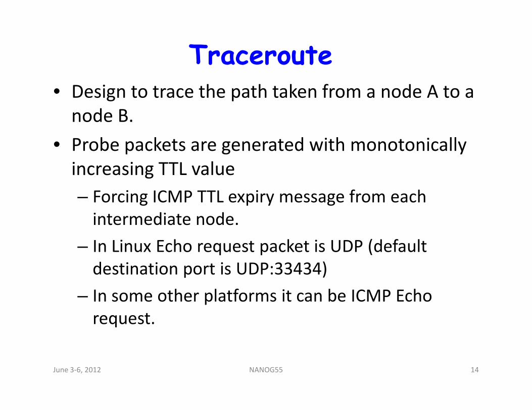
Traceroute• Design to trace the path taken from a node A to a
node B.
• Probe packets are generated with monotonically
increasing TTL value
– Forcing ICMP TTL expiry message from each – Forcing ICMP TTL expiry message from each
intermediate node.
– In Linux Echo request packet is UDP (default
destination port is UDP:33434)
– In some other platforms it can be ICMP Echo
request.
June 3-6, 2012 14NANOG55
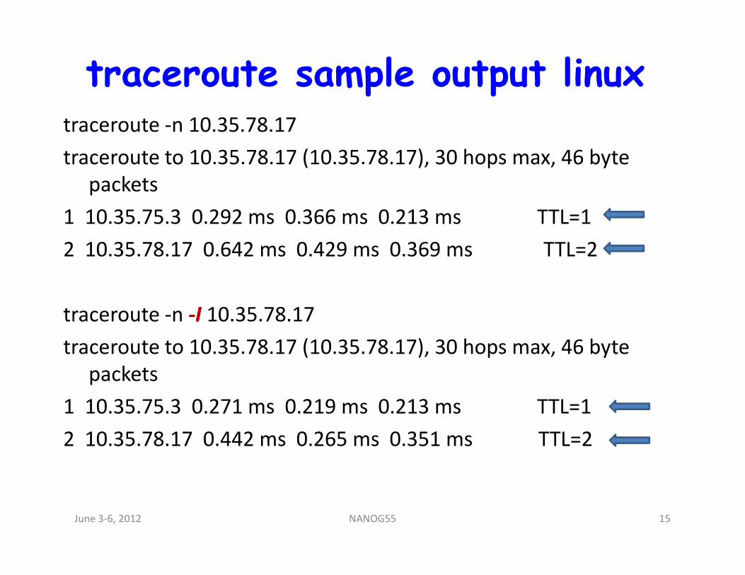
traceroute sample output linuxtraceroute -n 10.35.78.17
traceroute to 10.35.78.17 (10.35.78.17), 30 hops max, 46 byte
packets
1 10.35.75.3 0.292 ms 0.366 ms 0.213 ms TTL=1
2 10.35.78.17 0.642 ms 0.429 ms 0.369 ms TTL=2
traceroute -n --II 10.35.78.17
traceroute to 10.35.78.17 (10.35.78.17), 30 hops max, 46 byte
packets
1 10.35.75.3 0.271 ms 0.219 ms 0.213 ms TTL=1
2 10.35.78.17 0.442 ms 0.265 ms 0.351 ms TTL=2
June 3-6, 2012 15NANOG55
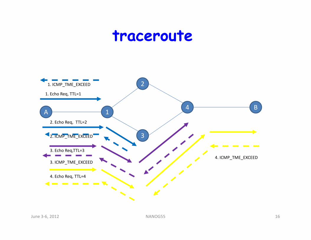
traceroute
A 1
2
4 B
1. Echo Req, TTL=1
2. Echo Req, TTL=2
1. ICMP_TME_EXCEED
32. ICMP_TME_EXCEED
2. Echo Req, TTL=2
3. Echo Req,TTL=3
3. ICMP_TME_EXCEED
4. Echo Req, TTL=4
4. ICMP_TME_EXCEED
June 3-6, 2012 16NANOG55
Challenges
• Over the years networking has evolved with that
comes OAM challenges
– ECMP (Equal Cost Multi Path)
– Multicast
– Tunneling (MPLS, PW, VPN, TRILL)– Tunneling (MPLS, PW, VPN, TRILL)
– Firewalls
• ICMP and more traditional OAM are designed for
unicast traffic with single path to the destination.
June 3-6, 2012 17NANOG55
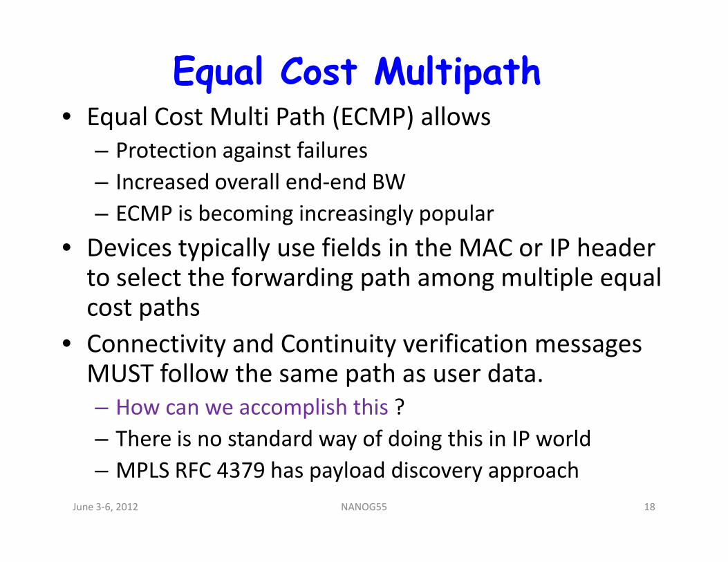
Equal Cost Multipath• Equal Cost Multi Path (ECMP) allows
– Protection against failures
– Increased overall end-end BW
– ECMP is becoming increasingly popular
• Devices typically use fields in the MAC or IP header to select the forwarding path among multiple equal to select the forwarding path among multiple equal cost paths
• Connectivity and Continuity verification messages MUST follow the same path as user data.
– How can we accomplish this ?
– There is no standard way of doing this in IP world
– MPLS RFC 4379 has payload discovery approach
June 3-6, 2012 18NANOG55
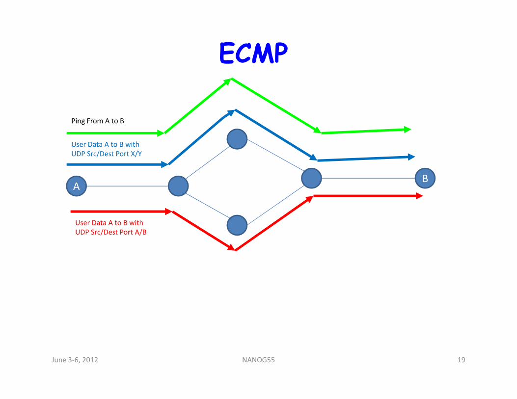
ECMP
AB
Ping From A to B
User Data A to B with
UDP Src/Dest Port X/Y
User Data A to B with
UDP Src/Dest Port A/B
June 3-6, 2012 19NANOG55
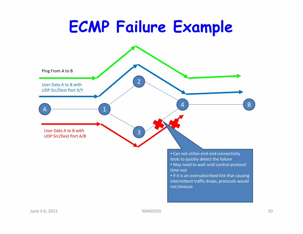
ECMP Failure Example
A 1
2
4 B
Ping From A to B
User Data A to B with
UDP Src/Dest Port X/Y
3User Data A to B with
UDP Src/Dest Port A/B
• Can not utilize end-end connectivity
tools to quickly detect the failure
• May need to wait until control protocol
time-out
• If it is an oversubscribed link that causing
intermittent traffic drops, protocols would
not timeout
June 3-6, 2012 20NANOG55
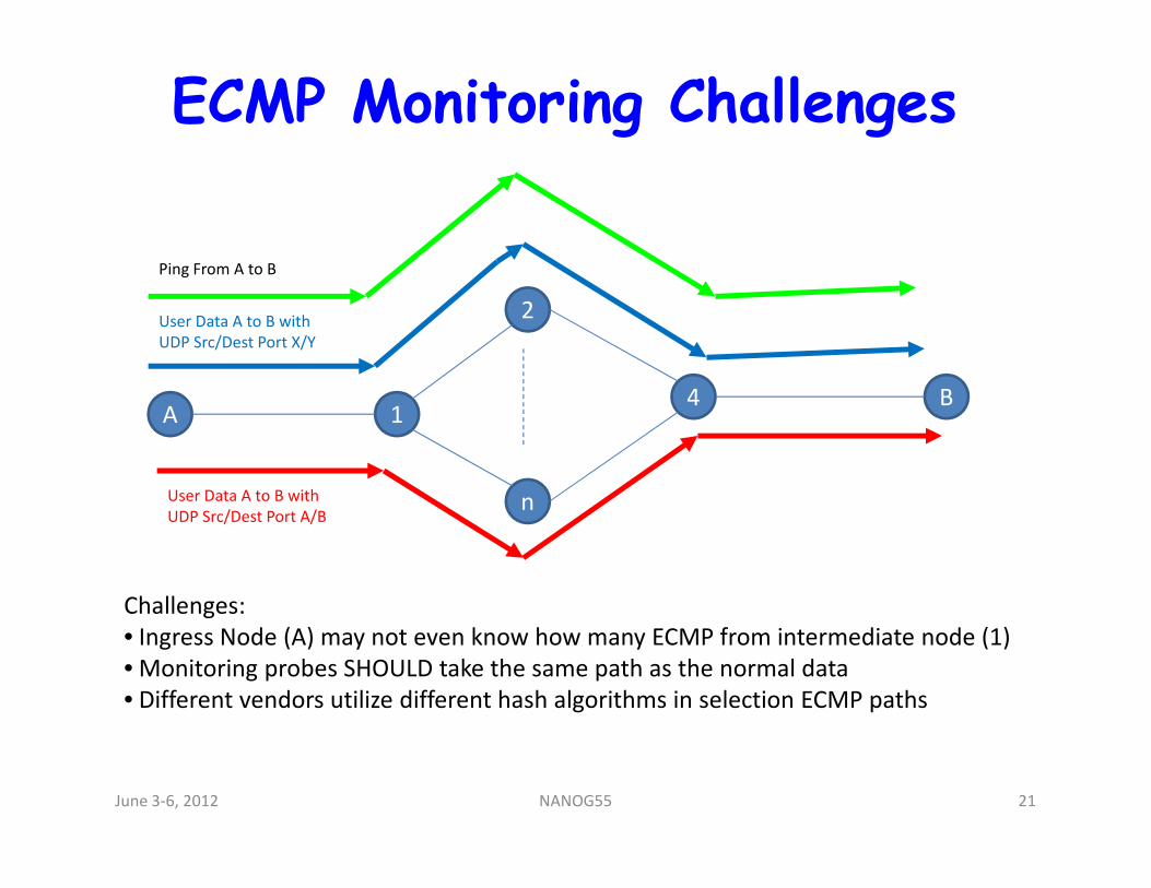
ECMP Monitoring Challenges
A 1
2
4 B
Ping From A to B
User Data A to B with
UDP Src/Dest Port X/Y
nUser Data A to B with
UDP Src/Dest Port A/B
Challenges:
• Ingress Node (A) may not even know how many ECMP from intermediate node (1)
• Monitoring probes SHOULD take the same path as the normal data
• Different vendors utilize different hash algorithms in selection ECMP paths
June 3-6, 2012 21NANOG55
ECMP challenges
• Conclusion
– No standard method to exercise end-end
continuity and connectivity verifications that
covers all of the ECMP in IP networks
June 3-6, 2012 22NANOG55
Agenda• Introduction
• Terms and Terminology
• An Introduction to Tools
• Introduction to MPLS
• MPLS TP 101
• Troubleshooting MPLS
• MPLS OAM
• LSP Ping
• ECMP troubleshooting
• BFD for MPLS
• Tools GaloreJune 3-6, 2012 23NANOG55
What is MPLS
• MPLS is acronym for Multi Protocol Label Switching
• Forwards traffic using labels
• Provides virtual connection (LSP) within the network
• Labels are allocated based on FEC
• Different types of label distribution• Different types of label distribution
• An LSP is usually unidirectional
• Ingress, Transit and Egress router types
• Traditional MPLS networks support PHP processing
• Supports different traffic types like ATM, FR, IP etc
• Private services like VPN for scalable service provider
requirementsJune 3-6, 2012 24NANOG55
MPLS LSP signaling protocols
• Resourced Reservation Protocol (RSVP)
� Extended to support Traffic Engineering
� Labels are assigned for identified path
� Explicit bandwidth reservation and paths
• Label Distribution Protocol (LDP)• Label Distribution Protocol (LDP)
� Labels are exchanged between neighbors
� IGP identifies the shortest path
• Constrained Routing LDP (CR-LDP)
� Traffic Engineering support using LDP
June 3-6, 2012 25NANOG55
Agenda
• Introduction
• Terms and Terminology
• An Introduction to Tools
• Introduction to MPLS
• MPLS TP 101• MPLS TP 101
• Troubleshooting MPLS
• MPLS OAM
• LSP Ping
• ECMP troubleshooting
• BFD for MPLS
• Tools GaloreJune 3-6, 2012 26NANOG55
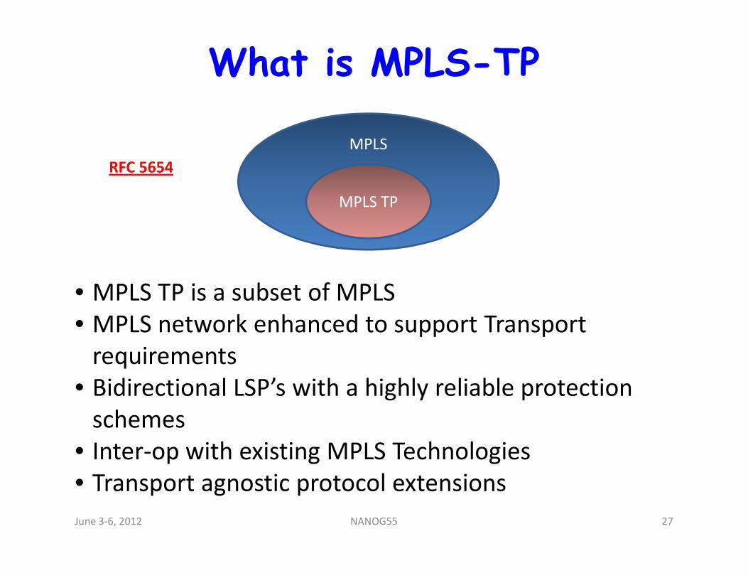
What is MPLS-TP
• MPLS TP is a subset of MPLS
MPLS
MPLS TP
RFC 5654
• MPLS TP is a subset of MPLS
• MPLS network enhanced to support Transport
requirements
• Bidirectional LSP’s with a highly reliable protection
schemes
• Inter-op with existing MPLS Technologies
• Transport agnostic protocol extensions
June 3-6, 2012 27NANOG55
What is being solved by MPLS-TP?
• Next Generation networks are moving
– SONET/SDH to Packet Switching
– Bandwidth hungry
– Lower cost with network resource sharing
• OPEX and CAPEX• OPEX and CAPEX
– Provisioning of paths
– OAM capabilities
– Fault detection and recovery mechanisms
– Path computation
– SLA requirementsJune 3-6, 2012 28NANOG55
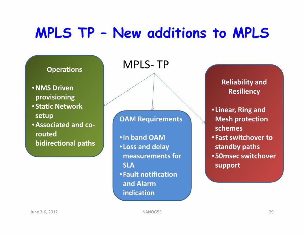
MPLS TP – New additions to MPLS
OAM Requirements
Operations
•NMS Driven
provisioning
•Static Network
setup
Reliability and
Resiliency
•Linear, Ring and
Mesh protection
MPLS- TP
OAM Requirements
• In band OAM
•Loss and delay
measurements for
SLA
•Fault notification
and Alarm
indication
setup
•Associated and co-
routed
bidirectional paths
Mesh protection
schemes
•Fast switchover to
standby paths
•50msec switchover
support
June 3-6, 2012 29NANOG55
Agenda• Introduction
• Terms and Terminology
• An Introduction to Tools
• Introduction to MPLS
• MPLS TP 101
• Troubleshooting MPLS
• MPLS OAM
• LSP Ping
• ECMP troubleshooting
• BFD for MPLS
• Tools GaloreJune 3-6, 2012 30NANOG55
Problems in MPLS Networks
• Control Plane is working, Data Plane is broken
• IGP working but MPLS control protocol is broken
• Proactive monitoring of End-to-End MPLS LSP’s
• Identifying the End-to-End packet path
• Unlabelled interface• Unlabelled interface
• MTU issues
• Performance degradation and unable to provide QoS
• Black holes
• ECMP Verification
June 3-6, 2012 31NANOG55
Primitive Debugging Methods
• ICMP provides connectivity verification
• VRF aware ping could test VPN path connectivity
• UDP ping could test the UDP transport
• Route table and Label table provides label entries
programmedprogrammed
• Interface status verification
• MPLS control plane protocols provides control plane
information
June 3-6, 2012 32NANOG55
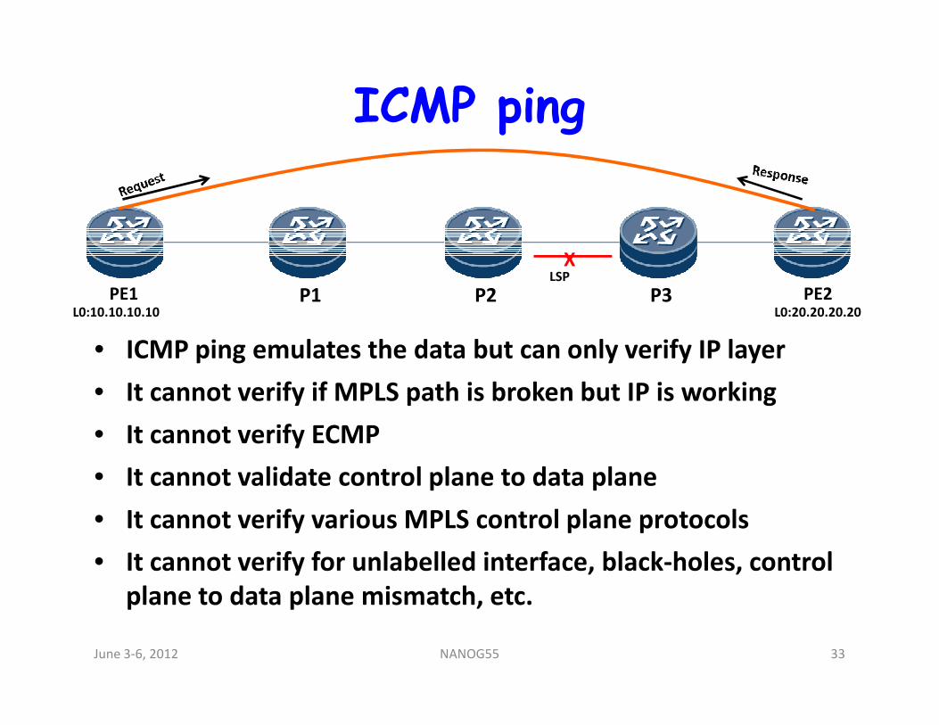
ICMP ping
• ICMP ping emulates the data but can only verify IP layer
PE1 P1 P2 P3 PE2L0:10.10.10.10 L0:20.20.20.20
XLSP
• ICMP ping emulates the data but can only verify IP layer
• It cannot verify if MPLS path is broken but IP is working
• It cannot verify ECMP
• It cannot validate control plane to data plane
• It cannot verify various MPLS control plane protocols
• It cannot verify for unlabelled interface, black-holes, control
plane to data plane mismatch, etc.
June 3-6, 2012 33NANOG55
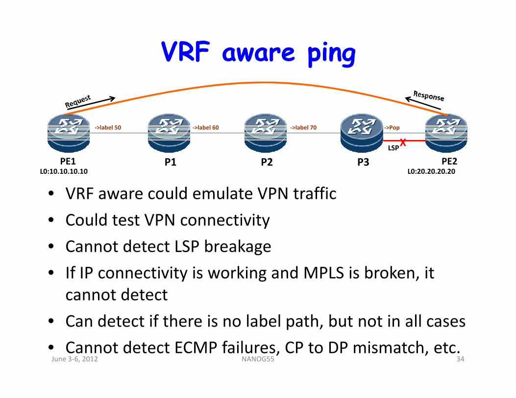
VRF aware ping
• VRF aware could emulate VPN traffic
PE1 P1 P2 P3 PE2L0:10.10.10.10 L0:20.20.20.20
XLSP
->label 50 ->label 60 ->label 70 ->Pop
• VRF aware could emulate VPN traffic
• Could test VPN connectivity
• Cannot detect LSP breakage
• If IP connectivity is working and MPLS is broken, it
cannot detect
• Can detect if there is no label path, but not in all cases
• Cannot detect ECMP failures, CP to DP mismatch, etc.June 3-6, 2012 34NANOG55
Agenda• Introduction
• Terms and Terminology
• An Introduction to Tools
• Introduction to MPLS
• MPLS TP 101
• Troubleshooting MPLS• Troubleshooting MPLS
• MPLS OAM
• LSP Ping
• ECMP troubleshooting
• BFD for MPLS
• Tools GaloreJune 3-6, 2012 35NANOG55
What is MPLS OAM• Operations, Administration and Maintenance of
MPLS Networks
• Perform proactive and on-demand troubleshooting
of MPLS Networks and devices
• Ability to measure MPLS network and aid user in
managing the networkmanaging the network
• Ability to diagnose defects which cannot be done at
other layers or using non-MPLS specific toolset
• Provide carrier class tool set to manage MPLS
networks
June 3-6, 2012 36NANOG55
Agenda• Introduction
• Terms and Terminology
• An Introduction to Tools
• Introduction to MPLS
• MPLS TP 101
• Troubleshooting MPLS
• MPLS OAM
• LSP Ping
• ECMP troubleshooting
• BFD for MPLS
• Tools GaloreJune 3-6, 2012 37NANOG55
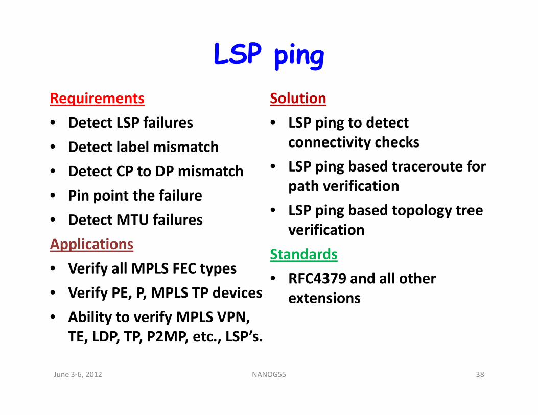
LSP ping
Requirements
• Detect LSP failures
• Detect label mismatch
• Detect CP to DP mismatch
• Pin point the failure
Solution
• LSP ping to detect
connectivity checks
• LSP ping based traceroute for
path verification
• LSP ping based topology tree • Detect MTU failures
Applications
• Verify all MPLS FEC types
• Verify PE, P, MPLS TP devices
• Ability to verify MPLS VPN,
TE, LDP, TP, P2MP, etc., LSP’s.
• LSP ping based topology tree
verification
Standards
• RFC4379 and all other
extensions
June 3-6, 2012 38NANOG55
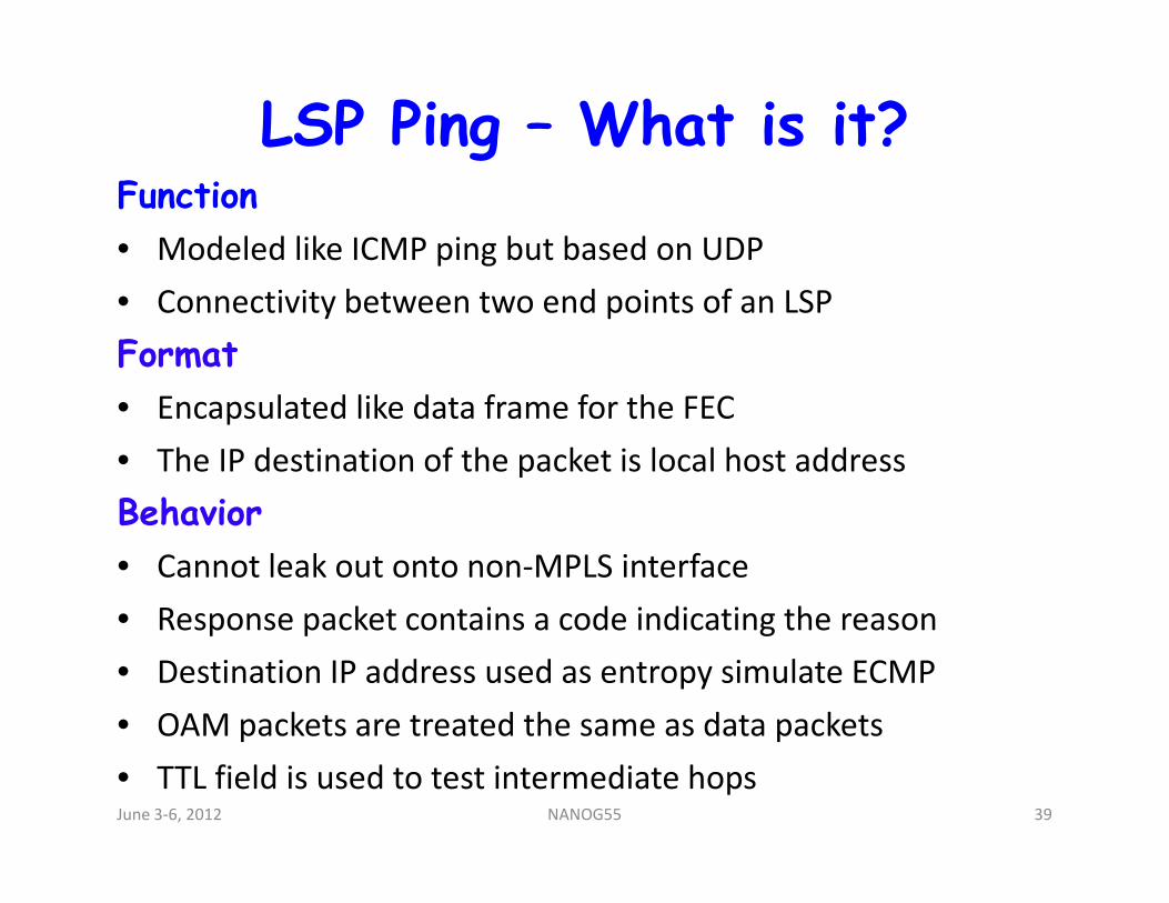
LSP Ping – What is it?Function
• Modeled like ICMP ping but based on UDP
• Connectivity between two end points of an LSP
Format
• Encapsulated like data frame for the FEC
• The IP destination of the packet is local host address• The IP destination of the packet is local host address
Behavior
• Cannot leak out onto non-MPLS interface
• Response packet contains a code indicating the reason
• Destination IP address used as entropy simulate ECMP
• OAM packets are treated the same as data packets
• TTL field is used to test intermediate hopsJune 3-6, 2012 39NANOG55
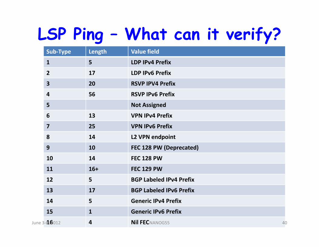
LSP Ping – What can it verify?Sub-Type Length Value field
1 5 LDP IPv4 Prefix
2 17 LDP IPv6 Prefix
3 20 RSVP IPV4 Prefix
4 56 RSVP IPv6 Prefix
5 Not Assigned
6 13 VPN IPv4 Prefix
7 25 VPN IPv6 Prefix7 25 VPN IPv6 Prefix
8 14 L2 VPN endpoint
9 10 FEC 128 PW (Deprecated)
10 14 FEC 128 PW
11 16+ FEC 129 PW
12 5 BGP Labeled IPv4 Prefix
13 17 BGP Labeled IPv6 Prefix
14 5 Generic IPv4 Prefix
15 1 Generic IPv6 Prefix
16 4 Nil FECJune 3-6, 2012 40NANOG55
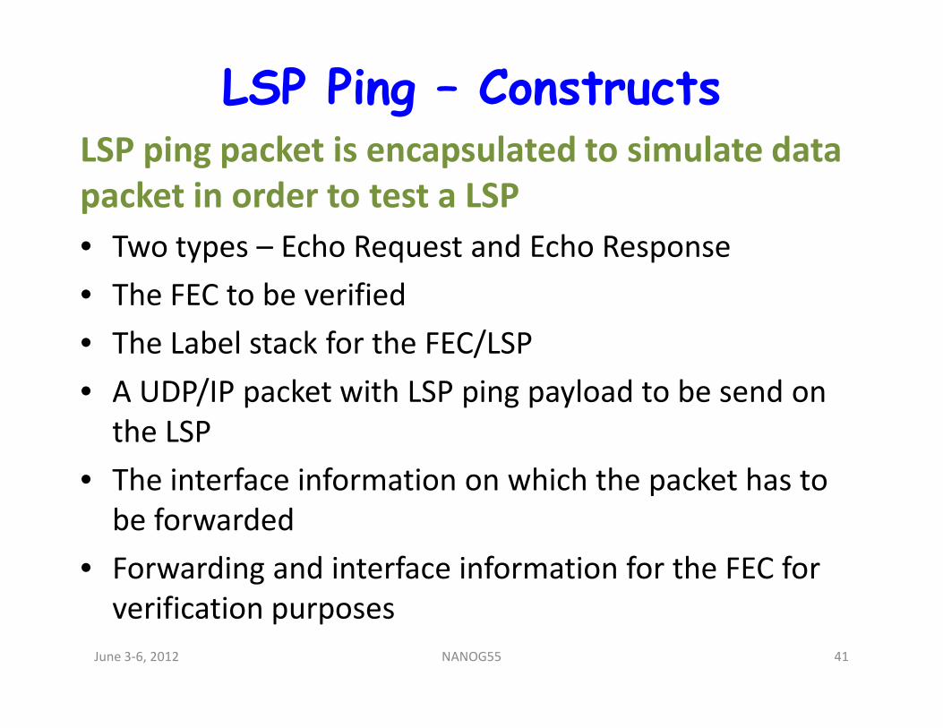
LSP Ping – ConstructsLSP ping packet is encapsulated to simulate data
packet in order to test a LSP
• Two types – Echo Request and Echo Response
• The FEC to be verified
• The Label stack for the FEC/LSP
• A UDP/IP packet with LSP ping payload to be send on
the LSP
• The interface information on which the packet has to
be forwarded
• Forwarding and interface information for the FEC for
verification purposes
June 3-6, 2012 41NANOG55
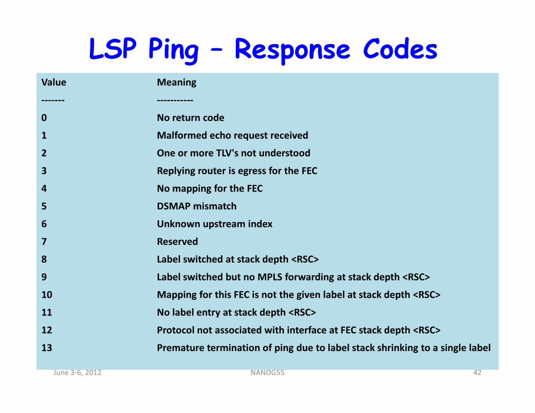
LSP Ping – Response CodesValue Meaning
------- -----------
0 No return code
1 Malformed echo request received
2 One or more TLV's not understood
3 Replying router is egress for the FEC
4 No mapping for the FEC
5 DSMAP mismatch5 DSMAP mismatch
6 Unknown upstream index
7 Reserved
8 Label switched at stack depth <RSC>
9 Label switched but no MPLS forwarding at stack depth <RSC>
10 Mapping for this FEC is not the given label at stack depth <RSC>
11 No label entry at stack depth <RSC>
12 Protocol not associated with interface at FEC stack depth <RSC>
13 Premature termination of ping due to label stack shrinking to a single label
June 3-6, 2012 42NANOG55
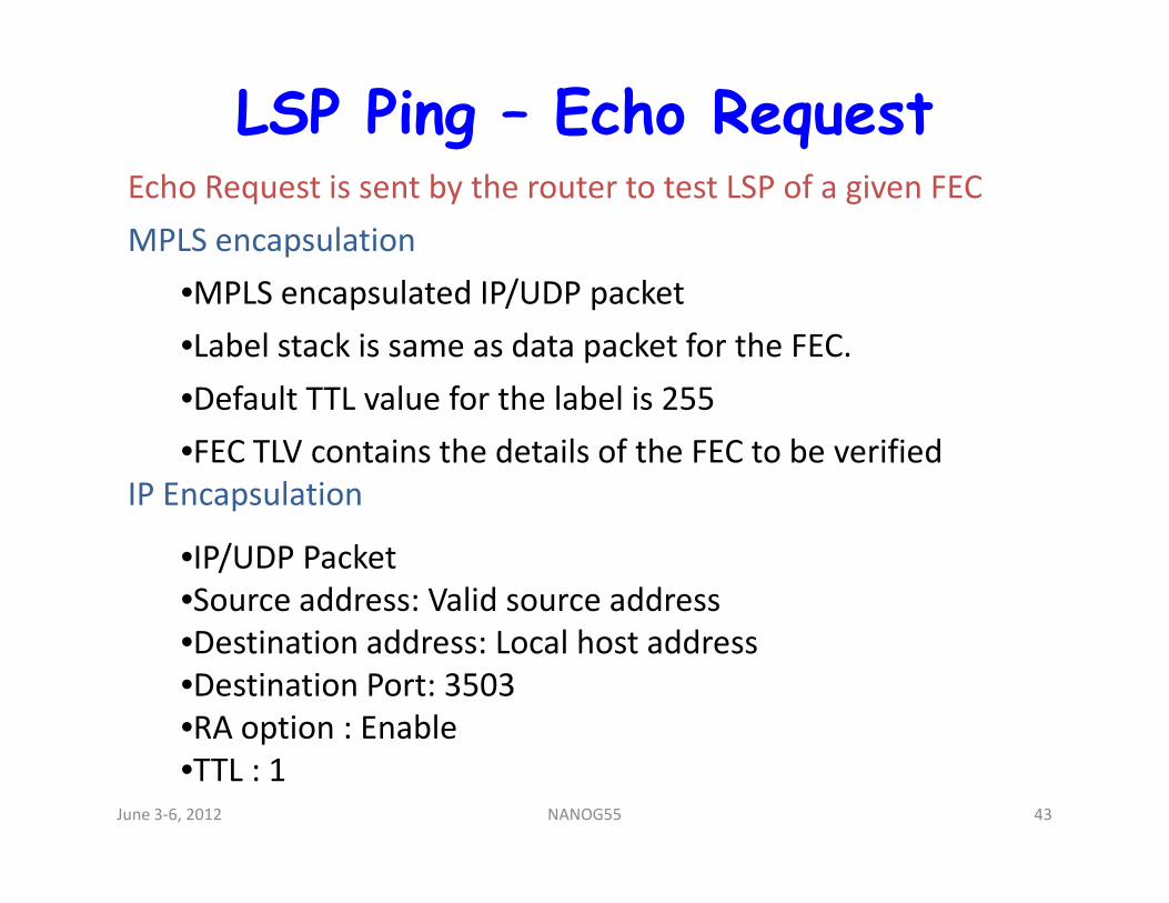
LSP Ping – Echo RequestEcho Request is sent by the router to test LSP of a given FEC
MPLS encapsulation
•MPLS encapsulated IP/UDP packet
•Label stack is same as data packet for the FEC.
•Default TTL value for the label is 255
•FEC TLV contains the details of the FEC to be verified•FEC TLV contains the details of the FEC to be verified
IP Encapsulation
•IP/UDP Packet
•Source address: Valid source address
•Destination address: Local host address
•Destination Port: 3503
•RA option : Enable
•TTL : 1 June 3-6, 2012 43NANOG55
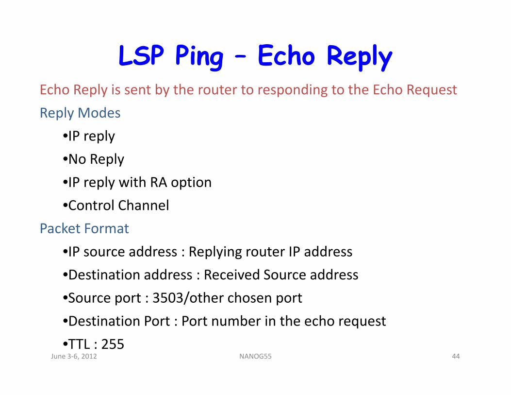
LSP Ping – Echo ReplyEcho Reply is sent by the router to responding to the Echo Request
Reply Modes
•IP reply
•No Reply
•IP reply with RA option
•Control Channel•Control Channel
Packet Format
•IP source address : Replying router IP address
•Destination address : Received Source address
•Source port : 3503/other chosen port
•Destination Port : Port number in the echo request
•TTL : 255June 3-6, 2012 44NANOG55
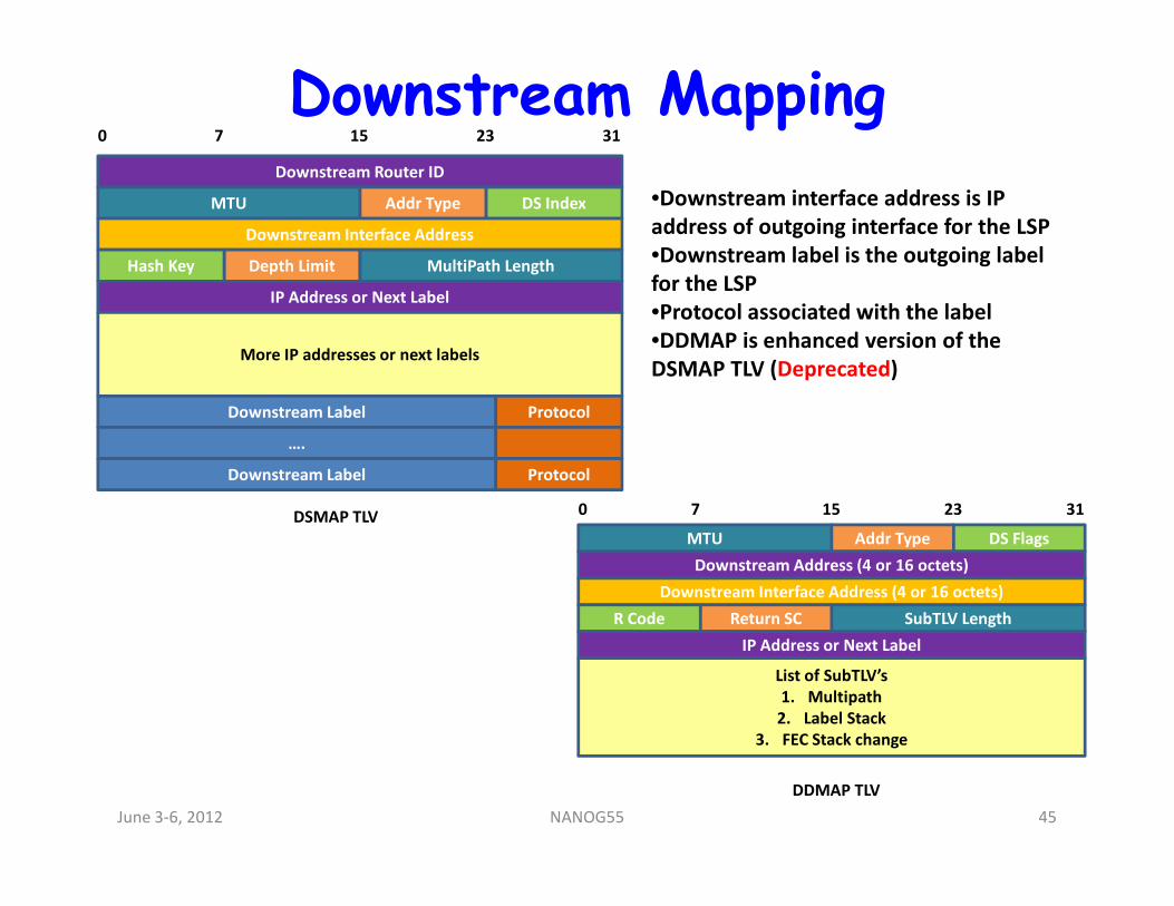
Downstream MappingDownstream Router ID
MTU Addr Type DS Index
Downstream Interface Address
Depth LimitHash Key MultiPath Length
IP Address or Next Label
More IP addresses or next labels
Downstream Label Protocol
….
0 15 23 317
•Downstream interface address is IP
address of outgoing interface for the LSP
•Downstream label is the outgoing label
for the LSP
•Protocol associated with the label
•DDMAP is enhanced version of the
DSMAP TLV (Deprecated)
Downstream Label Protocol
DSMAP TLV
MTU Addr Type DS Flags
Downstream Interface Address (4 or 16 octets)
Return SCR Code SubTLV Length
IP Address or Next Label
List of SubTLV’s
1. Multipath
2. Label Stack
3. FEC Stack change
0 15 23 317
Downstream Address (4 or 16 octets)
DDMAP TLV
June 3-6, 2012 45NANOG55
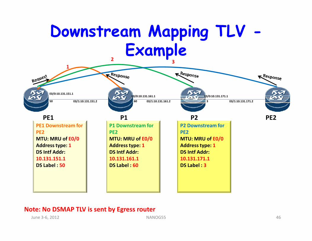
Downstream Mapping TLV -Example
PE1 P1 P2 PE2
E0/0:10.131.151.1
E0/1:10.131.161.2
E0/0:10.131.161.1
E0/1:10.131.151.2
E0/0:10.131.171.1
E0/1:10.131.171.250 60 3
1
23
PE1 P1 P2 PE2PE1 Downstream for
PE2
MTU: MRU of E0/0
Address type: 1
DS Intf Addr:
10.131.151.1
DS Label : 50
P1 Downstream for
PE2
MTU: MRU of E0/0
Address type: 1
DS Intf Addr:
10.131.161.1
DS Label : 60
P2 Downstream for
PE2
MTU: MRU of E0/0
Address type: 1
DS Intf Addr:
10.131.171.1
DS Label : 3
Note: No DSMAP TLV is sent by Egress routerJune 3-6, 2012 46NANOG55
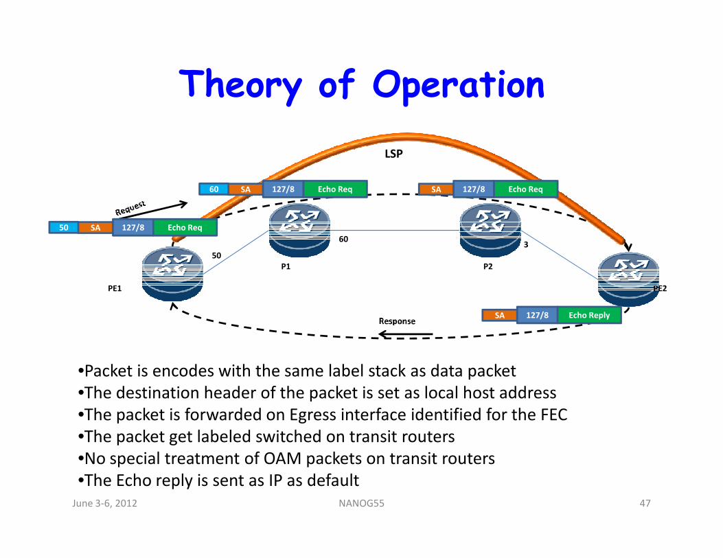
Theory of Operation
P1 P2
SA 127/8 Echo Req50
SA 127/8 Echo Req60 SA 127/8 Echo Req
50
603
LSP
PE1 PE2
SA 127/8 Echo Reply
•Packet is encodes with the same label stack as data packet
•The destination header of the packet is set as local host address
•The packet is forwarded on Egress interface identified for the FEC
•The packet get labeled switched on transit routers
•No special treatment of OAM packets on transit routers
•The Echo reply is sent as IP as default
June 3-6, 2012 47NANOG55
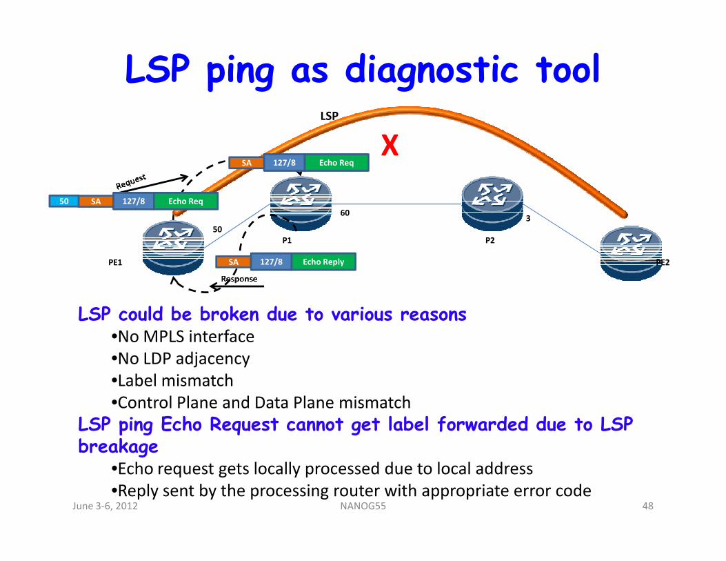
LSP ping as diagnostic tool
PE1
P1 P2
PE2
SA 127/8 Echo Req50
SA 127/8 Echo Req
50
603
SA 127/8 Echo Reply
LSP
X
LSP could be broken due to various reasons•No MPLS interface
•No LDP adjacency
•Label mismatch
•Control Plane and Data Plane mismatch
LSP ping Echo Request cannot get label forwarded due to LSP breakage
•Echo request gets locally processed due to local address
•Reply sent by the processing router with appropriate error codeJune 3-6, 2012 48NANOG55
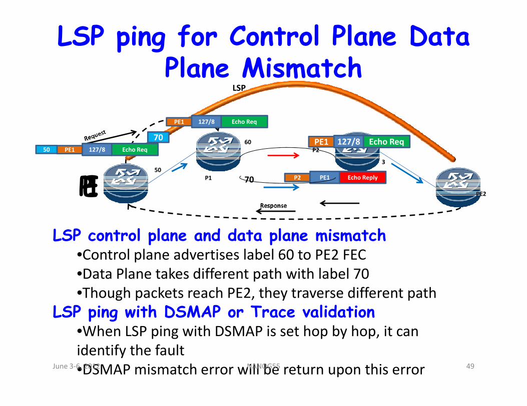
LSP ping for Control Plane Data Plane Mismatch
PE1P1
P2
PE2
PE1 127/8 Echo Req50
PE1 127/8 Echo Req
50
60
3
P2 PE1 Echo Reply
LSP
70
70PE1 127/8 Echo Req
LSP control plane and data plane mismatch•Control plane advertises label 60 to PE2 FEC
•Data Plane takes different path with label 70
•Though packets reach PE2, they traverse different path
LSP ping with DSMAP or Trace validation•When LSP ping with DSMAP is set hop by hop, it can
identify the fault
•DSMAP mismatch error will be return upon this errorJune 3-6, 2012 49NANOG55
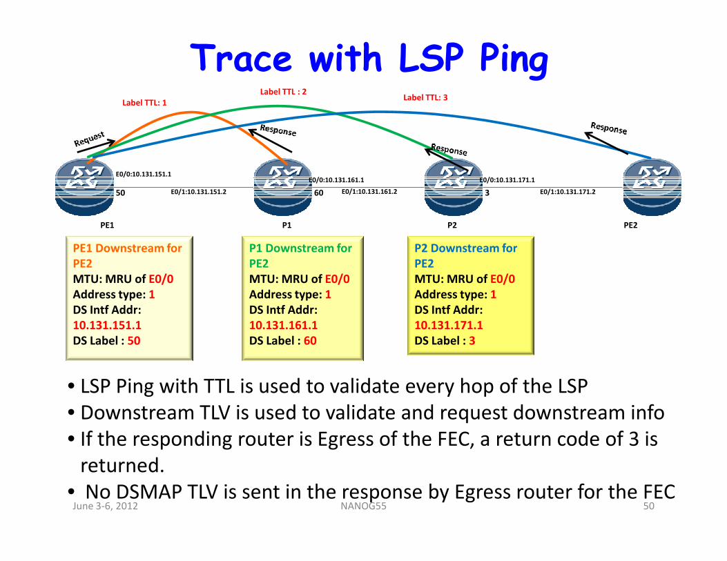
Trace with LSP Ping
PE1 P1 P2 PE2
E0/0:10.131.151.1
E0/1:10.131.161.2
E0/0:10.131.161.1
E0/1:10.131.151.2
E0/0:10.131.171.1
E0/1:10.131.171.250 60 3
PE1 Downstream for
PE2
MTU: MRU of E0/0
P1 Downstream for
PE2
MTU: MRU of E0/0
P2 Downstream for
PE2
MTU: MRU of E0/0
Label TTL: 1
Label TTL : 2Label TTL: 3
MTU: MRU of E0/0
Address type: 1
DS Intf Addr:
10.131.151.1
DS Label : 50
MTU: MRU of E0/0
Address type: 1
DS Intf Addr:
10.131.161.1
DS Label : 60
MTU: MRU of E0/0
Address type: 1
DS Intf Addr:
10.131.171.1
DS Label : 3
• LSP Ping with TTL is used to validate every hop of the LSP
• Downstream TLV is used to validate and request downstream info
• If the responding router is Egress of the FEC, a return code of 3 is
returned.
• No DSMAP TLV is sent in the response by Egress router for the FECJune 3-6, 2012 50NANOG55
Agenda• Introduction
• Terms and Terminology
• An Introduction to Tools
• Introduction to MPLS
• MPLS TP 101
• Troubleshooting MPLS
• MPLS OAM
• LSP Ping
• ECMP troubleshooting
• BFD for MPLS
• Tools GaloreJune 3-6, 2012 51NANOG55
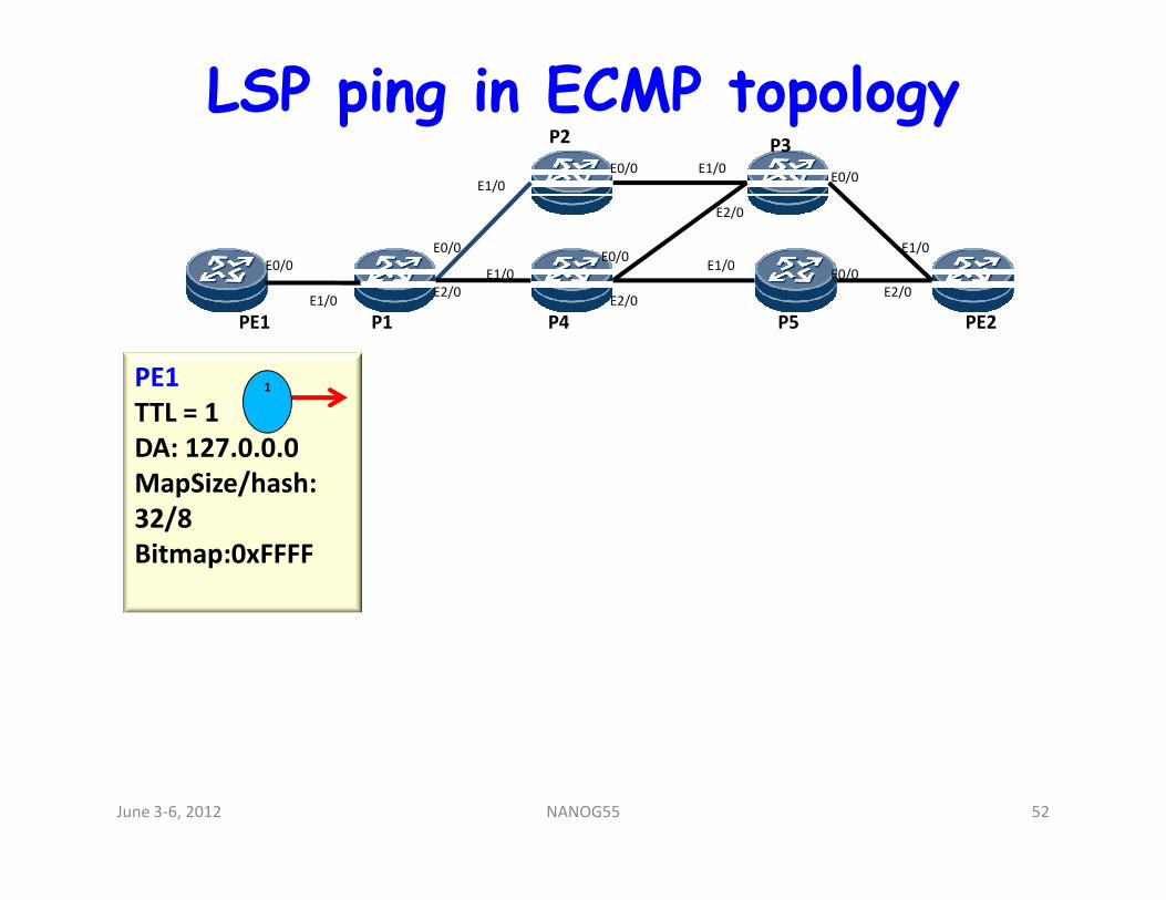
LSP ping in ECMP topology
PE1
P2
P1 P4
P3
PE2P5
E0/0
E1/0
E0/0
E1/0
E1/0
E2/0
E0/0
E2/0
E1/0
E1/0E0/0
E2/0
E1/0
E2/0
E0/0
E0/0
PE1
TTL = 1
DA: 127.0.0.0
1
DA: 127.0.0.0
MapSize/hash:
32/8
Bitmap:0xFFFF
June 3-6, 2012 52NANOG55
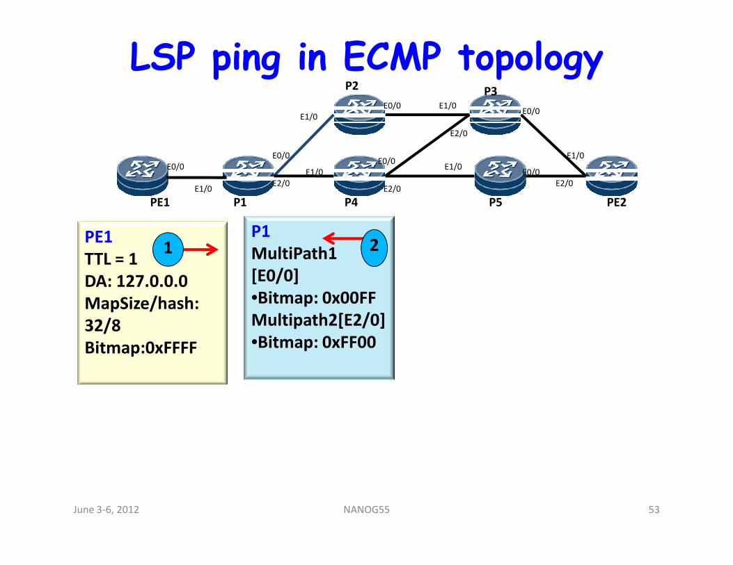
LSP ping in ECMP topology
PE1
P2
P1 P4
P3
PE2P5
E0/0
E1/0
E0/0
E1/0
E1/0
E2/0
E0/0
E2/0
E1/0
E1/0E0/0
E2/0
E1/0
E2/0
E0/0
E0/0
PE1
TTL = 1
DA: 127.0.0.0
1P1
MultiPath1
[E0/0]
2
DA: 127.0.0.0
MapSize/hash:
32/8
Bitmap:0xFFFF
[E0/0]
•Bitmap: 0x00FF
Multipath2[E2/0]
•Bitmap: 0xFF00
June 3-6, 2012 53NANOG55
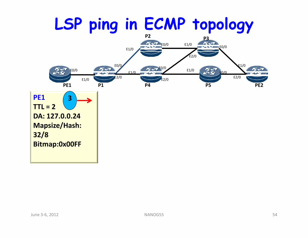
LSP ping in ECMP topology
PE1
P2
P1 P4
P3
PE2P5
E0/0
E1/0
E0/0
E1/0
E1/0
E2/0
E0/0
E2/0
E1/0
E1/0E0/0
E2/0
E1/0
E2/0
E0/0
E0/0
PE1
TTL = 2
DA: 127.0.0.24
3
DA: 127.0.0.24
Mapsize/Hash:
32/8
Bitmap:0x00FF
June 3-6, 2012 54NANOG55
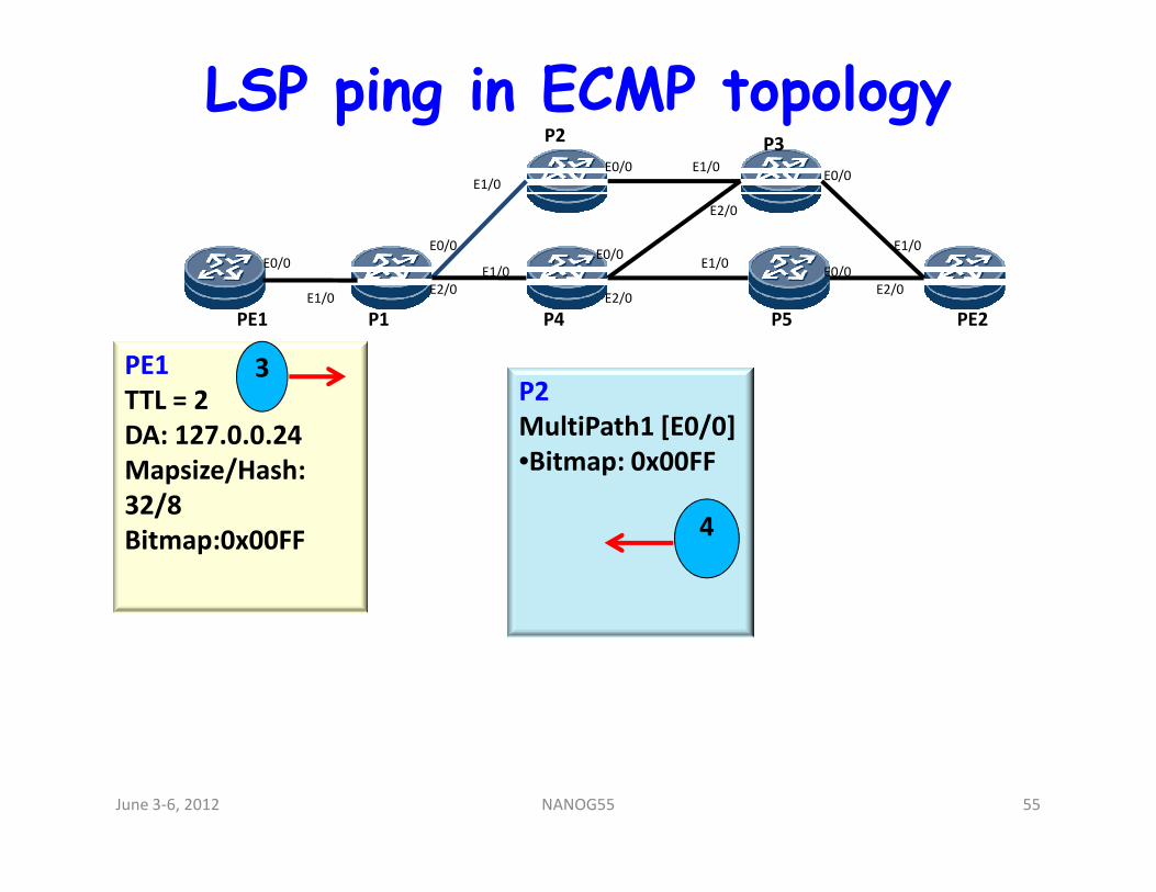
LSP ping in ECMP topology
PE1
P2
P1 P4
P3
PE2P5
E0/0
E1/0
E0/0
E1/0
E1/0
E2/0
E0/0
E2/0
E1/0
E1/0E0/0
E2/0
E1/0
E2/0
E0/0
E0/0
PE1
TTL = 2
DA: 127.0.0.24
3P2
MultiPath1 [E0/0]
•Bitmap: 0x00FFDA: 127.0.0.24
Mapsize/Hash:
32/8
Bitmap:0x00FF
•Bitmap: 0x00FF
4
June 3-6, 2012 55NANOG55
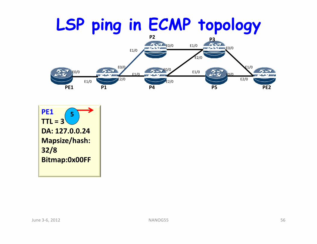
LSP ping in ECMP topology
PE1
P2
P1 P4
P3
PE2P5
E0/0
E1/0
E0/0
E1/0
E1/0
E2/0
E0/0
E2/0
E1/0
E1/0E0/0
E2/0
E1/0
E2/0
E0/0
E0/0
PE1
TTL = 35
TTL = 3
DA: 127.0.0.24
Mapsize/hash:
32/8
Bitmap:0x00FF
June 3-6, 2012 56NANOG55
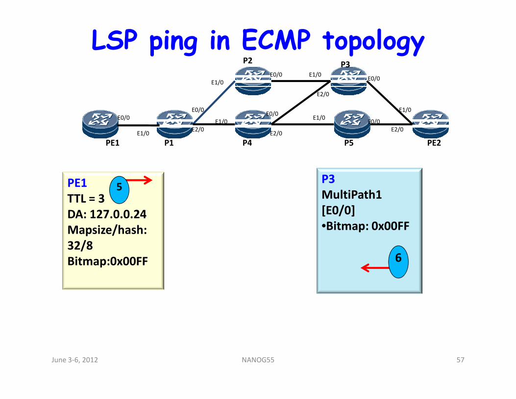
LSP ping in ECMP topology
PE1
P2
P1 P4
P3
PE2P5
E0/0
E1/0
E0/0
E1/0
E1/0
E2/0
E0/0
E2/0
E1/0
E1/0E0/0
E2/0
E1/0
E2/0
E0/0
E0/0
PE1
TTL = 35
P3
MultiPath1 TTL = 3
DA: 127.0.0.24
Mapsize/hash:
32/8
Bitmap:0x00FF
MultiPath1
[E0/0]
•Bitmap: 0x00FF
6
June 3-6, 2012 57NANOG55
LSP ping in ECMP topology
PE1
P2
P1 P4
P3
PE2P5
E0/0
E1/0
E0/0
E1/0
E1/0
E2/0
E0/0
E2/0
E1/0
E1/0E0/0
E2/0
E1/0
E2/0
E0/0
E0/0
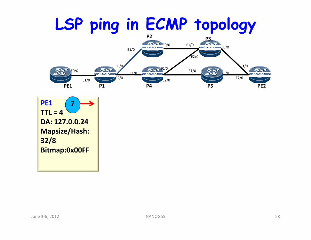
PE1
TTL = 4
DA: 127.0.0.24
7
DA: 127.0.0.24
Mapsize/Hash:
32/8
Bitmap:0x00FF
June 3-6, 2012 58NANOG55
LSP ping in ECMP topology
PE1
P2
P1 P4
P3
PE2P5
E0/0
E1/0
E0/0
E1/0
E1/0
E2/0
E0/0
E2/0
E1/0
E1/0E0/0
E2/0
E1/0
E2/0
E0/0
E0/0
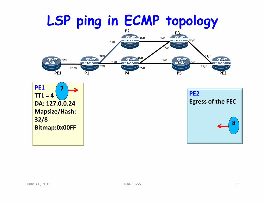
PE1
TTL = 4
DA: 127.0.0.24
7PE2
Egress of the FECDA: 127.0.0.24
Mapsize/Hash:
32/8
Bitmap:0x00FF
Egress of the FEC
8
June 3-6, 2012 59NANOG55
LSP ping in ECMP topology
PE1
P2
P1 P4
P3
PE2P5
E0/0
E1/0
E0/0
E1/0
E1/0
E2/0
E0/0
E2/0
E1/0
E1/0E0/0
E2/0
E1/0
E2/0
E0/0
E0/0
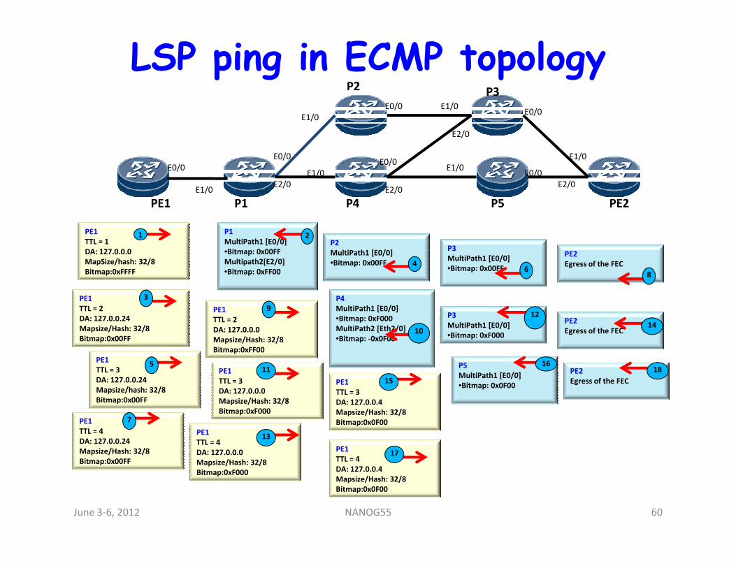
PE1
TTL = 1
DA: 127.0.0.0
MapSize/hash: 32/8
Bitmap:0xFFFF
1P2
MultiPath1 [E0/0]
•Bitmap: 0x00FF 4
P1
MultiPath1 [E0/0]
•Bitmap: 0x00FF
Multipath2[E2/0]
•Bitmap: 0xFF00
2
P3
MultiPath1 [E0/0]
•Bitmap: 0x00FF 6
PE2
Egress of the FEC
8
PE1
TTL = 2
DA: 127.0.0.24
Mapsize/Hash: 32/8
Bitmap:0x00FF
3
PE1
TTL = 3
DA: 127.0.0.24
Mapsize/hash: 32/8
Bitmap:0x00FF
5
P4
MultiPath1 [E0/0]
•Bitmap: 0xF000
MultiPath2 [Eth2/0]
•Bitmap: -0x0F0010
P5
MultiPath1 [E0/0]
•Bitmap: 0x0F00
16
PE1
TTL = 4
DA: 127.0.0.24
Mapsize/Hash: 32/8
Bitmap:0x00FF
7
PE1
TTL = 2
DA: 127.0.0.0
Mapsize/Hash: 32/8
Bitmap:0xFF00
9
PE1
TTL = 3
DA: 127.0.0.0
Mapsize/Hash: 32/8
Bitmap:0xF000
11
P3
MultiPath1 [E0/0]
•Bitmap: 0xF000
12
PE1
TTL = 4
DA: 127.0.0.0
Mapsize/Hash: 32/8
Bitmap:0xF000
13
PE2
Egress of the FEC14
PE1
TTL = 3
DA: 127.0.0.4
Mapsize/Hash: 32/8
Bitmap:0x0F00
15
PE1
TTL = 4
DA: 127.0.0.4
Mapsize/Hash: 32/8
Bitmap:0x0F00
17
PE2
Egress of the FEC
18
June 3-6, 2012 60NANOG55
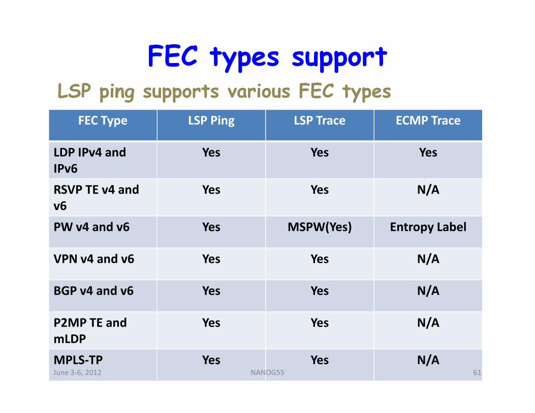
FEC types supportLSP ping supports various FEC types
FEC Type LSP Ping LSP Trace ECMP Trace
LDP IPv4 and
IPv6
Yes Yes Yes
RSVP TE v4 and
v6
Yes Yes N/A
v6
PW v4 and v6 Yes MSPW(Yes) Entropy Label
VPN v4 and v6 Yes Yes N/A
BGP v4 and v6 Yes Yes N/A
P2MP TE and
mLDP
Yes Yes N/A
MPLS-TP Yes Yes N/AJune 3-6, 2012 61NANOG55
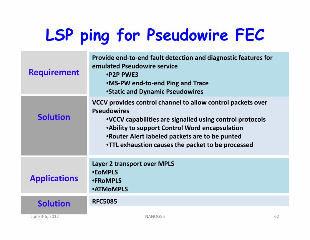
LSP ping for Pseudowire FEC
Requirement
Provide end-to-end fault detection and diagnostic features for
emulated Pseudowire service
•P2P PWE3
•MS-PW end-to-end Ping and Trace
•Static and Dynamic Pseudowires
Solution
VCCV provides control channel to allow control packets over
Pseudowires
•VCCV capabilities are signalled using control protocolsSolution •VCCV capabilities are signalled using control protocols
•Ability to support Control Word encapsulation
•Router Alert labeled packets are to be punted
•TTL exhaustion causes the packet to be processed
Applications
Layer 2 transport over MPLS
•EoMPLS
•FRoMPLS
•ATMoMPLS
Solution RFC5085
June 3-6, 2012 62NANOG55
Agenda• Introduction
• Terms and Terminology
• An Introduction to Tools
• Introduction to MPLS
• MPLS TP 101
• Troubleshooting MPLS
• MPLS OAM
• LSP Ping
• ECMP troubleshooting
• BFD for MPLS
• Tools GaloreJune 3-6, 2012 63NANOG55
Bidirectional Forward Detection (BFD)
• Simple fixed-field, hello protocol
• Packets are periodically transmitted over respective
directions of the path
• If a node stops receiving BFD packets, some component
of the bidirectional path is assumed to have failed.of the bidirectional path is assumed to have failed.
• Several modes of operation
June 3-6, 2012 64NANOG55
BFD protocol Overview
• Typical hello protocol
• Neighbors continuously negotiate transmit and receive
rates in micro seconds
• Dynamic rate adaption
• Neighbor is declared down when hello packets don’t
show up
• Uses UDP/IP or Non IP packets as BFD packets
• Ability to support single-hop and multi-hop
June 3-6, 2012 65NANOG55
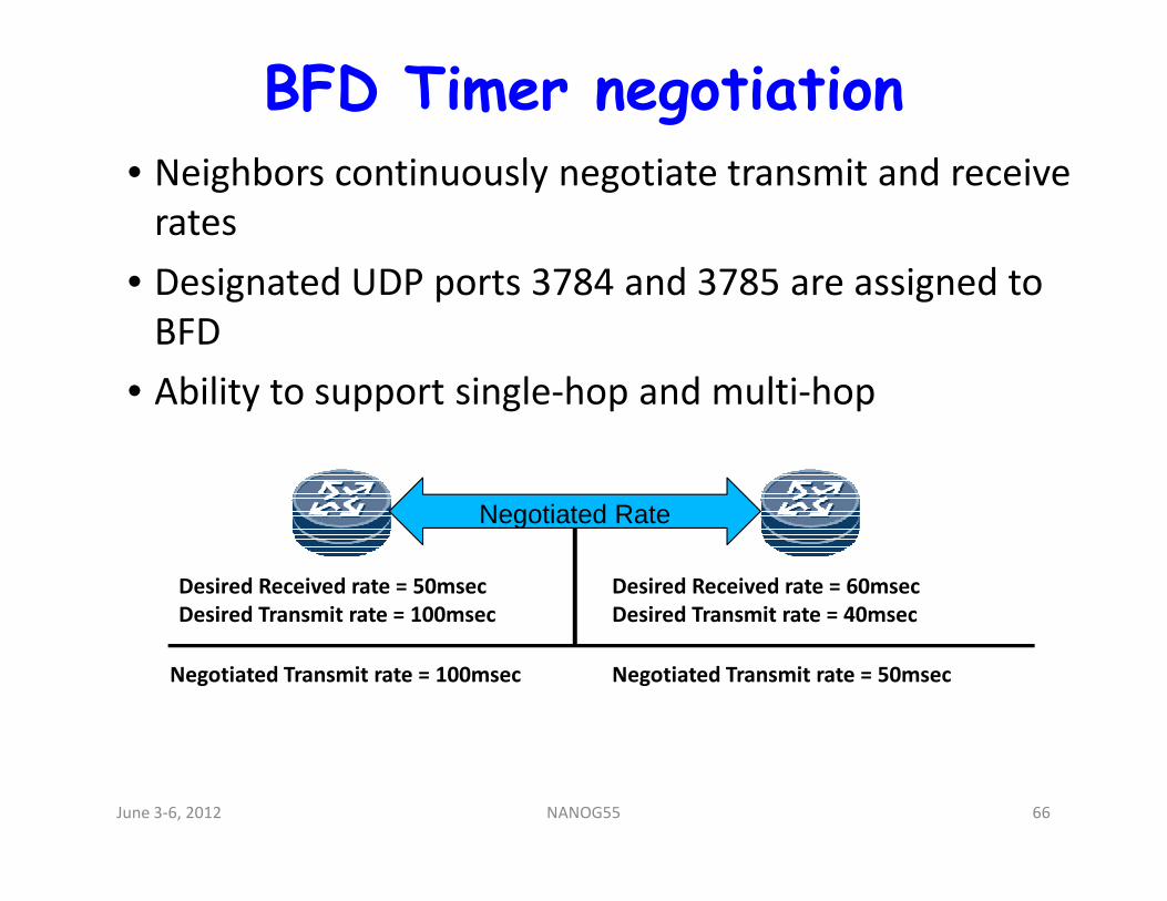
BFD Timer negotiation• Neighbors continuously negotiate transmit and receive
rates
• Designated UDP ports 3784 and 3785 are assigned to
BFD
• Ability to support single-hop and multi-hop
Negotiated Rate
Desired Received rate = 50msec
Desired Transmit rate = 100msec
Desired Received rate = 60msec
Desired Transmit rate = 40msec
Negotiated Transmit rate = 100msec Negotiated Transmit rate = 50msec
June 3-6, 2012 66NANOG55
BFD for MPLS• Ability to verify LSP
• BFD to verify TE tunnels, TP tunnels, PW LSP’s etc
• VCCV to be used to verify PW LSP’s
• BFD could be used to complement or replace use of
RSVP hellos for MPLS FRR Link/Node protection
• BFD to carry AIS, RDI errors to end points of TP tunnels• BFD to carry AIS, RDI errors to end points of TP tunnels
• BFD the primary mechanism to make fast switchover
and meet transport requirements
• BFD to play complimentary role to provide OAM within
MPLS
June 3-6, 2012 67NANOG55
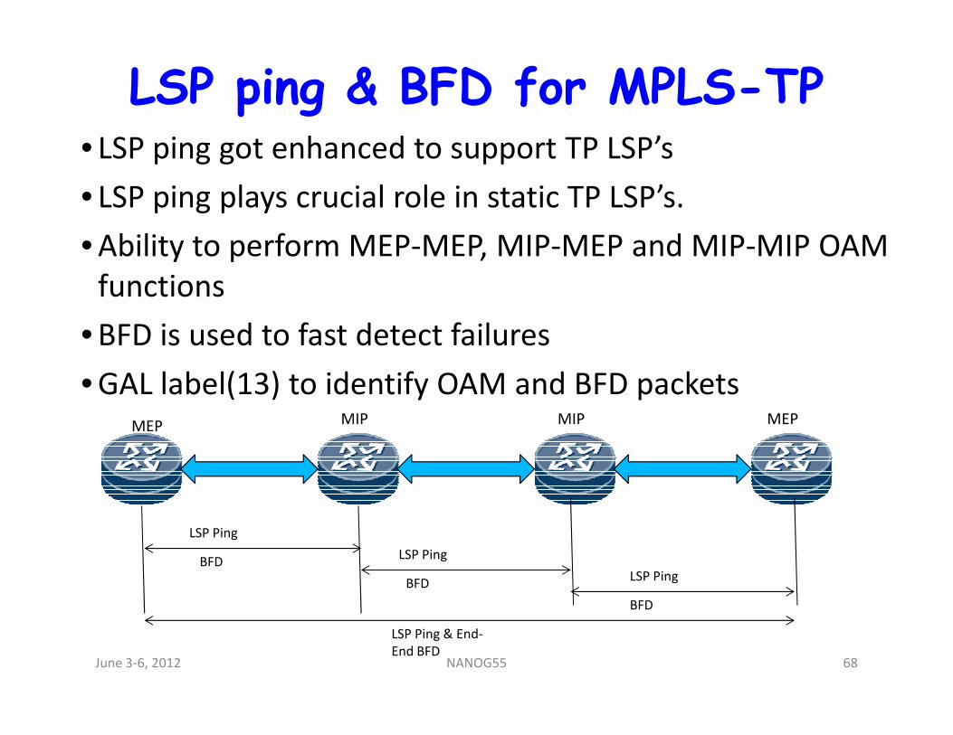
LSP ping & BFD for MPLS-TP• LSP ping got enhanced to support TP LSP’s
• LSP ping plays crucial role in static TP LSP’s.
• Ability to perform MEP-MEP, MIP-MEP and MIP-MIP OAM
functions
• BFD is used to fast detect failures
• GAL label(13) to identify OAM and BFD packets• GAL label(13) to identify OAM and BFD packetsMEP MIPMIP MEP
LSP Ping
LSP Ping
LSP Ping
LSP Ping & End-
End BFD
BFD
BFD
BFD
June 3-6, 2012 68NANOG55
Agenda• Introduction
• Terms and Terminology
• An Introduction to Tools
• Introduction to MPLS
• MPLS TP 101
• Troubleshooting MPLS
• MPLS OAM
• LSP Ping
• ECMP troubleshooting
• BFD for MPLS
• Tools GaloreJune 3-6, 2012 69NANOG55
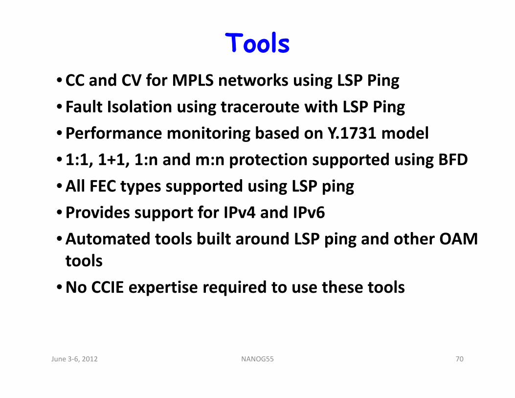
Tools• CC and CV for MPLS networks using LSP Ping
• Fault Isolation using traceroute with LSP Ping
• Performance monitoring based on Y.1731 model
• 1:1, 1+1, 1:n and m:n protection supported using BFD
• All FEC types supported using LSP ping
• Provides support for IPv4 and IPv6
• Automated tools built around LSP ping and other OAM
tools
• No CCIE expertise required to use these tools
June 3-6, 2012 70NANOG55
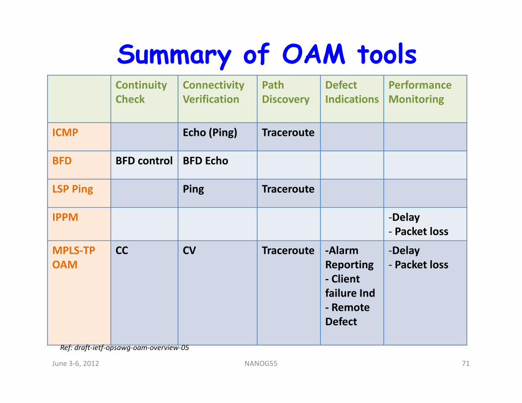
Summary of OAM toolsContinuity
Check
Connectivity
Verification
Path
Discovery
Defect
Indications
Performance
Monitoring
ICMP Echo (Ping) Traceroute
BFD BFD control BFD Echo
LSP Ping Ping Traceroute
IPPM -Delay
- Packet loss
MPLS-TP
OAM
CC CV Traceroute -Alarm
Reporting
- Client
failure Ind
- Remote
Defect
-Delay
- Packet loss
Ref: draft-ietf-opsawg-oam-overview-05
June 3-6, 2012 71NANOG55

Summary
June 3-6, 2012 72NANOG55
Summary
• MPLS OAM covers all types of MPLS networks
• No CCIE’s required to manage MPLS networks
• Already built into major vendors MPLS devices
• Deployed and being used in major carrier networks
• Inter-op tests carried out at various labs prove the OAM • Inter-op tests carried out at various labs prove the OAM
technologies WORK
• MPLS-TP brought forth the usefulness of OAM in
transport networks
• “MPLS OAM” a proven technology
June 3-6, 2012 73NANOG55

Questions
June 3-6, 2012 74NANOG55