mpls-based metro ethernet
TRANSCRIPT
Paresh Khatri
Feb, 2013
MPLS-based Metro Ethernet NetworksA Tutorial
COPYRIGHT © 2013 ALCATEL-LUCENT. ALL RIGHTS RESERVED. SLIDE 2
Agenda
Introduction to Metro Ethernet Services
Traditional Metro Ethernet networks
Delivering Ethernet over MPLS
Summary
Questions

COPYRIGHT © 2013 ALCATEL-LUCENT. ALL RIGHTS RESERVED. SLIDE 3
1. Introduction
COPYRIGHT © 2013 ALCATEL-LUCENT. ALL RIGHTS RESERVED. SLIDE 4
Paresh Khatri ([email protected])
Director – IP Competence Centre, APAC Pre-Sales, Alcatel-Lucent
Key focus areas:
Large-scale IP/MPLS networks
L2/L3 VPNs
Carrier Ethernet
Next-generation mobile backhaul networks
Acknowledgements:
Some figures and text are provided courtesy of the Metro Ethernet Forum (MEF)
Introduction

COPYRIGHT © 2013 ALCATEL-LUCENT. ALL RIGHTS RESERVED. SLIDE 5
2. Introduction to Metro Ethernet Services
COPYRIGHT © 2013 ALCATEL-LUCENT. ALL RIGHTS RESERVED. SLIDE 6
Agenda
2. Introduction to Metro Ethernet Services
2.1 Why Metro Ethernet ?
2.2 Attributes of Carrier Ethernet
2.3 Carrier Ethernet Services defined by the MEF
COPYRIGHT © 2013 ALCATEL-LUCENT. ALL RIGHTS RESERVED. SLIDE 7
2.1 Why Metro Ethernet ?
COPYRIGHT © 2013 ALCATEL-LUCENT. ALL RIGHTS RESERVED. SLIDE 8
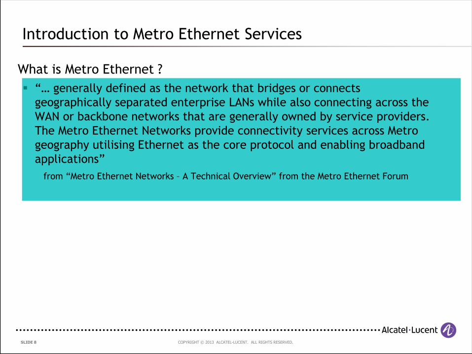
What is Metro Ethernet ?
“… generally defined as the network that bridges or connects
geographically separated enterprise LANs while also connecting across the
WAN or backbone networks that are generally owned by service providers.
The Metro Ethernet Networks provide connectivity services across Metro
geography utilising Ethernet as the core protocol and enabling broadband
applications”
from “Metro Ethernet Networks – A Technical Overview” from the Metro Ethernet Forum
Introduction to Metro Ethernet Services
COPYRIGHT © 2013 ALCATEL-LUCENT. ALL RIGHTS RESERVED. SLIDE 9
Why Metro Ethernet ?
Benefits both providers and customers in numerous ways …
Packet traffic has now overtaken all other traffic types
Need for rapid provisioning
Reduced CAPEX/OPEX
Increased and flexible bandwidth options
Well-known interfaces and technology
Introduction to Metro Ethernet Services
COPYRIGHT © 2013 ALCATEL-LUCENT. ALL RIGHTS RESERVED. SLIDE 10
2.2 Attributes of Carrier Ethernet
COPYRIGHT © 2013 ALCATEL-LUCENT. ALL RIGHTS RESERVED. SLIDE 11
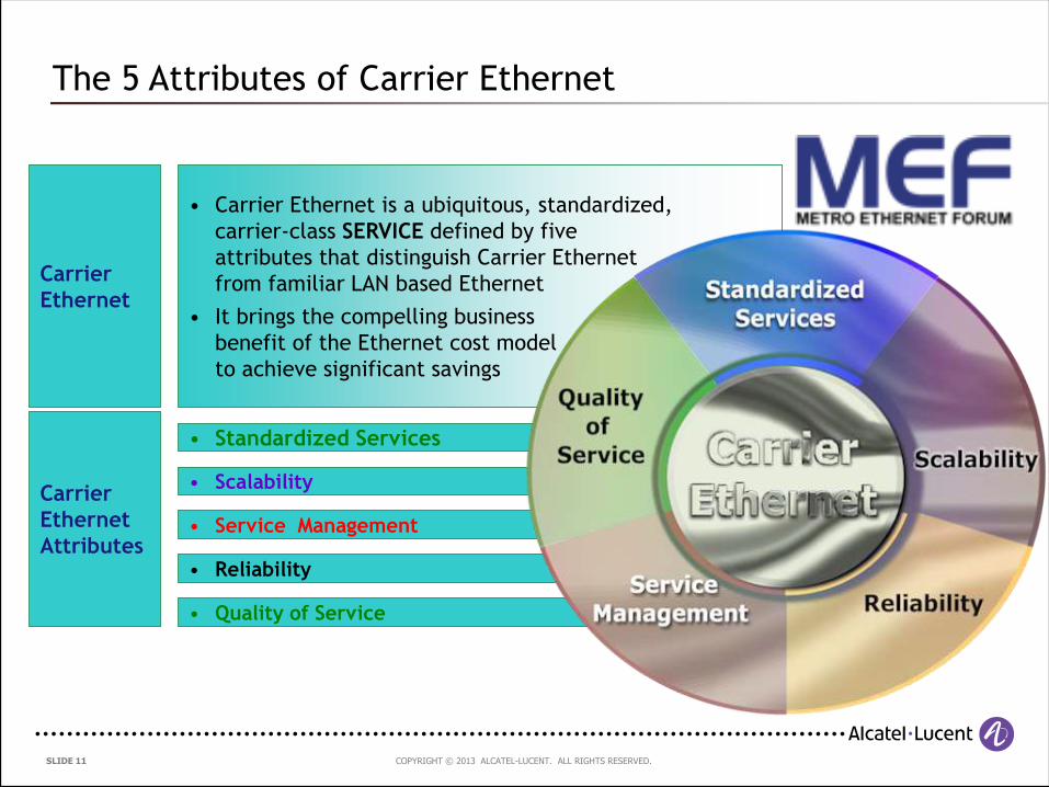
• Carrier Ethernet is a ubiquitous, standardized,
carrier-class SERVICE defined by five
attributes that distinguish Carrier Ethernet
from familiar LAN based Ethernet
• It brings the compelling business
benefit of the Ethernet cost model
to achieve significant savings
Carrier
Ethernet
• Scalability
• Standardized Services
• Service Management
• Quality of Service
• Reliability
Carrier
Ethernet
Attributes
The 5 Attributes of Carrier Ethernet
COPYRIGHT © 2013 ALCATEL-LUCENT. ALL RIGHTS RESERVED. SLIDE 12
2.3 Carrier Ethernet Services defined by the MEF
COPYRIGHT © 2013 ALCATEL-LUCENT. ALL RIGHTS RESERVED. SLIDE 13
What do we mean by Metro Ethernet services ?
Use of Ethernet access tails
Provision of Ethernet-based services across the MAN/WAN
Point-to-point
Point-to-multipoint
Multipoint-to-multipoint
However, the underlying infrastructure used to deliver Ethernet services
does NOT have to be Ethernet !!!
Referred to as Carrier Ethernet services by the Metro Ethernet Forum
The terms “Carrier Ethernet” and “Metro Ethernet” are used interchangeably in
this presentation, but in the strict sense of the term, “Carrier Ethernet” refers to
the carrier-grade evolution of “Metro Ethernet”
Introduction to Metro Ethernet Services
COPYRIGHT © 2013 ALCATEL-LUCENT. ALL RIGHTS RESERVED. SLIDE 14
Carrier Ethernet Network
UNI
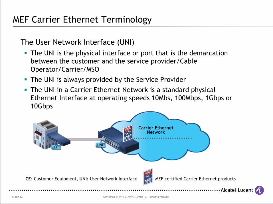
The User Network Interface (UNI)
The UNI is the physical interface or port that is the demarcation
between the customer and the service provider/Cable
Operator/Carrier/MSO
The UNI is always provided by the Service Provider
The UNI in a Carrier Ethernet Network is a standard physical
Ethernet Interface at operating speeds 10Mbs, 100Mbps, 1Gbps or
10Gbps
CE: Customer Equipment, UNI: User Network Interface. MEF certified Carrier Ethernet products
CE
MEF Carrier Ethernet Terminology
COPYRIGHT © 2013 ALCATEL-LUCENT. ALL RIGHTS RESERVED. SLIDE 15
Carrier Ethernet Network
UNI
MEF Carrier Ethernet Terminology
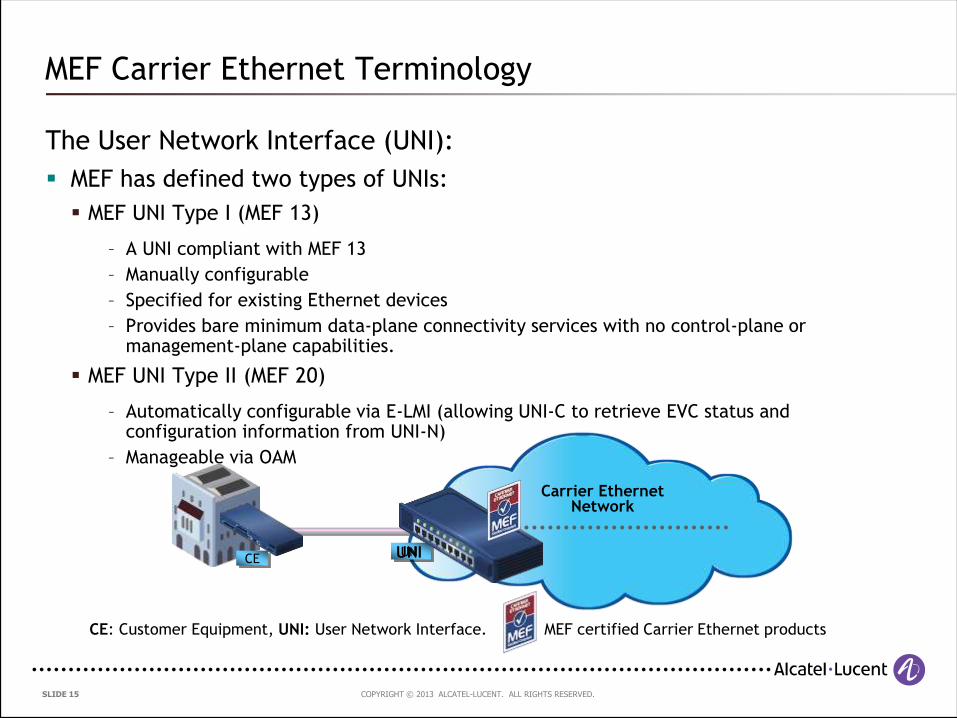
The User Network Interface (UNI):
MEF has defined two types of UNIs:
MEF UNI Type I (MEF 13)
– A UNI compliant with MEF 13
– Manually configurable
– Specified for existing Ethernet devices
– Provides bare minimum data-plane connectivity services with no control-plane or management-plane capabilities.
MEF UNI Type II (MEF 20)
– Automatically configurable via E-LMI (allowing UNI-C to retrieve EVC status and configuration information from UNI-N)
– Manageable via OAM
CE: Customer Equipment, UNI: User Network Interface. MEF certified Carrier Ethernet products
CE UNI
COPYRIGHT © 2013 ALCATEL-LUCENT. ALL RIGHTS RESERVED. SLIDE 16
MetroMetro
EthernetEthernet
NetworkNetwork
CustomerCustomer
EdgeEdge
(CE)(CE)
User NetworkUser Network
InterfaceInterface
(UNI)(UNI)
User NetworkUser Network
InterfaceInterface
(UNI)(UNI)
CustomerCustomer
EdgeEdge
(CE)(CE)
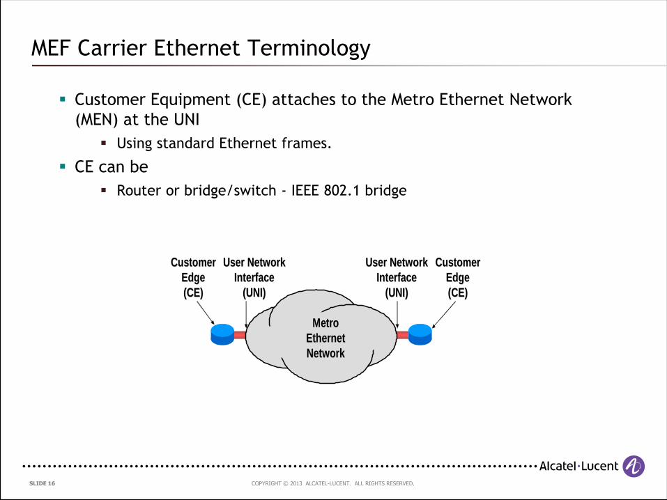
MEF Carrier Ethernet Terminology
Customer Equipment (CE) attaches to the Metro Ethernet Network
(MEN) at the UNI
Using standard Ethernet frames.
CE can be
Router or bridge/switch - IEEE 802.1 bridge
COPYRIGHT © 2013 ALCATEL-LUCENT. ALL RIGHTS RESERVED. SLIDE 17
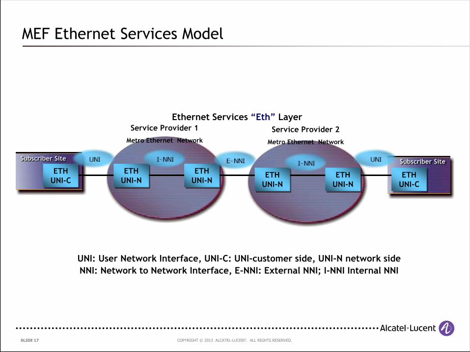
Ethernet Services “Eth” Layer
Subscriber Site
Service Provider 1
Metro Ethernet Network
Service Provider 2
Metro Ethernet Network
Subscriber Site
ETH
UNI-C
ETH
UNI-N
ETH
UNI-NETH
UNI-N
ETH
UNI-N
ETH
UNI-C
UNI: User Network Interface, UNI-C: UNI-customer side, UNI-N network side
NNI: Network to Network Interface, E-NNI: External NNI; I-NNI Internal NNI
MEF Ethernet Services Model
COPYRIGHT © 2013 ALCATEL-LUCENT. ALL RIGHTS RESERVED. SLIDE 18
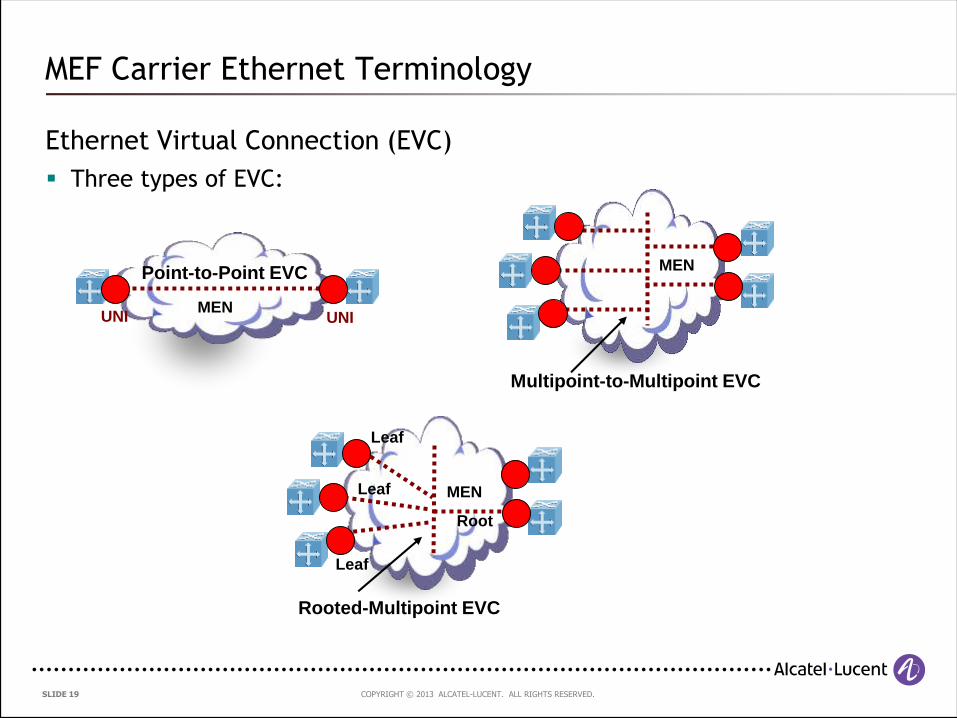
MEF Carrier Ethernet Terminology
Ethernet Virtual Connection (EVC)
An Ethernet Service Instantiation
Most commonly (but not necessarily) identified via a VLAN-ID
Like Frame Relay and ATM PVCs or SVCs
Connects two or more subscriber sites (UNI’s)
Can multiplex multiple EVCs on the same UNI
An association of two or more UNIs
Prevents data transfer between sites that are not part of the same EVC
COPYRIGHT © 2013 ALCATEL-LUCENT. ALL RIGHTS RESERVED. SLIDE 19
MEF Carrier Ethernet Terminology
Ethernet Virtual Connection (EVC)
Three types of EVC:
UNIMEN
UNI
Point-to-Point EVC MEN
Multipoint-to-Multipoint EVC
MEN
Rooted-Multipoint EVC
Leaf
Leaf
Leaf
Root
COPYRIGHT © 2013 ALCATEL-LUCENT. ALL RIGHTS RESERVED. SLIDE 20
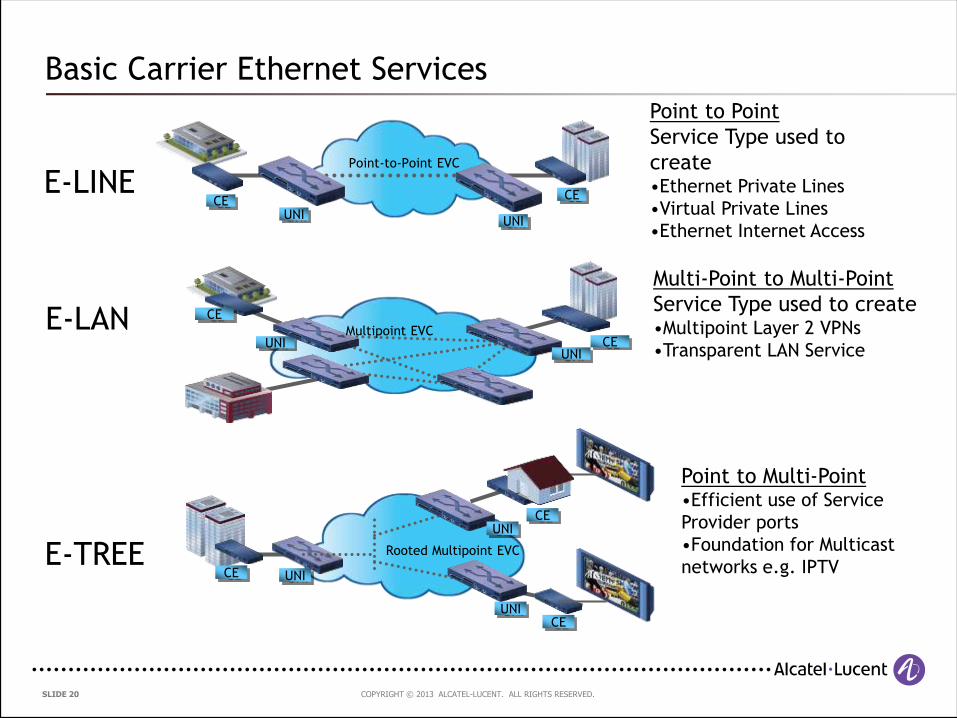
E-LINE
E-LAN
Point to Point
Service Type used to
create•Ethernet Private Lines
•Virtual Private Lines
•Ethernet Internet Access
E-TREE
Point to Multi-Point•Efficient use of Service
Provider ports
•Foundation for Multicast
networks e.g. IPTV
Multi-Point to Multi-Point
Service Type used to create•Multipoint Layer 2 VPNs
•Transparent LAN Service
Point-to-Point EVC
CEUNI
UNI
CE
CE
UNI CEUNI
Multipoint EVC
Rooted Multipoint EVC
CE UNI
CEUNI
CEUNI
Basic Carrier Ethernet Services
COPYRIGHT © 2013 ALCATEL-LUCENT. ALL RIGHTS RESERVED. SLIDE 21
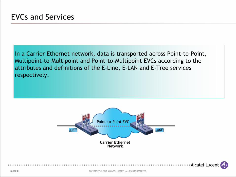
EVCs and Services
In a Carrier Ethernet network, data is transported across Point-to-Point,
Multipoint-to-Multipoint and Point-to-Multipoint EVCs according to the
attributes and definitions of the E-Line, E-LAN and E-Tree services
respectively.
Point-to-Point EVC
Carrier Ethernet Network
UNI UNI
COPYRIGHT © 2013 ALCATEL-LUCENT. ALL RIGHTS RESERVED. SLIDE 22
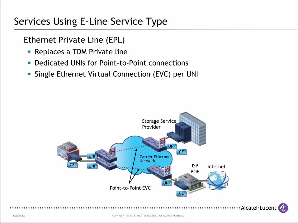
Services Using E-Line Service Type
Ethernet Private Line (EPL)
Replaces a TDM Private line
Dedicated UNIs for Point-to-Point connections
Single Ethernet Virtual Connection (EVC) per UNI
Point-to-Point EVC
Carrier Ethernet Network
CE UNI
CE
UNI
CE
UNI
ISP
POP
UNI
Storage Service
Provider
Internet
COPYRIGHT © 2013 ALCATEL-LUCENT. ALL RIGHTS RESERVED. SLIDE 23
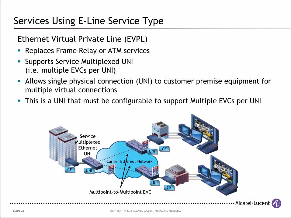
Services Using E-Line Service Type
Ethernet Virtual Private Line (EVPL)
Replaces Frame Relay or ATM services
Supports Service Multiplexed UNI
(i.e. multiple EVCs per UNI)
Allows single physical connection (UNI) to customer premise equipment for
multiple virtual connections
This is a UNI that must be configurable to support Multiple EVCs per UNI
Service
Multiplexed
Ethernet
UNI
Multipoint-to-Multipoint EVC
Carrier Ethernet Network
CE UNI
CEUNI
CE
UNI
COPYRIGHT © 2013 ALCATEL-LUCENT. ALL RIGHTS RESERVED. SLIDE 24
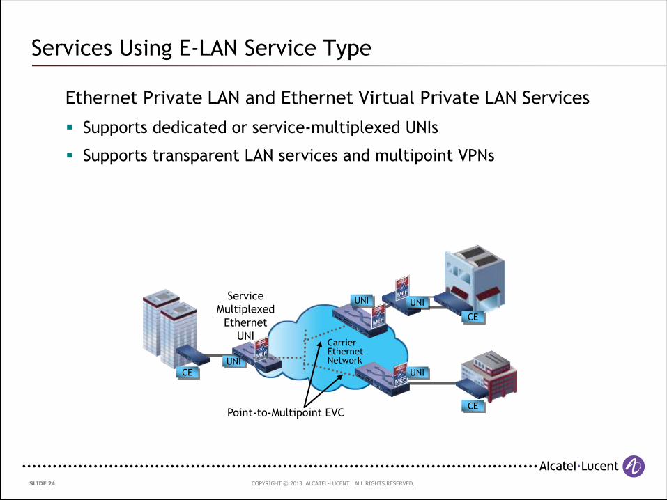
Services Using E-LAN Service Type
Ethernet Private LAN and Ethernet Virtual Private LAN Services
Supports dedicated or service-multiplexed UNIs
Supports transparent LAN services and multipoint VPNs
Service
Multiplexed
Ethernet
UNI
Point-to-Multipoint EVC
Carrier Ethernet Network
CE
UNI
UNI
UNI
CE
UNI
CE
COPYRIGHT © 2013 ALCATEL-LUCENT. ALL RIGHTS RESERVED. SLIDE 25
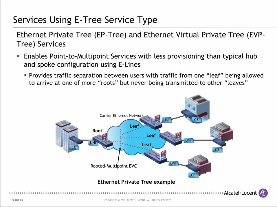
Services Using E-Tree Service Type
Ethernet Private Tree (EP-Tree) and Ethernet Virtual Private Tree (EVP-
Tree) Services
Enables Point-to-Multipoint Services with less provisioning than typical hub
and spoke configuration using E-Lines
Provides traffic separation between users with traffic from one “leaf” being allowed
to arrive at one of more “roots” but never being transmitted to other “leaves”
Root
Carrier Ethernet Network
CE
UNI
UNI
UNI
CE
CE
Leaf
Leaf
UNI
CE
Leaf
Rooted-Multipoint EVC
Ethernet Private Tree example
COPYRIGHT © 2013 ALCATEL-LUCENT. ALL RIGHTS RESERVED. SLIDE 26
Name any two of the five attributes of Carrier Ethernet as defined by the Metro Ethernet
Forum.
Audience Question 1

COPYRIGHT © 2013 ALCATEL-LUCENT. ALL RIGHTS RESERVED. SLIDE 27
3. Traditional Metro Ethernet networks
COPYRIGHT © 2013 ALCATEL-LUCENT. ALL RIGHTS RESERVED. SLIDE 28
Agenda
3. Traditional Metro Ethernet Networks
3.1 Service Identification
3.2 Forwarding Mechanism
3.3 Resiliency and Redundancy
3.4 Recent Developments
3.5 Summary
COPYRIGHT © 2013 ALCATEL-LUCENT. ALL RIGHTS RESERVED. SLIDE 29
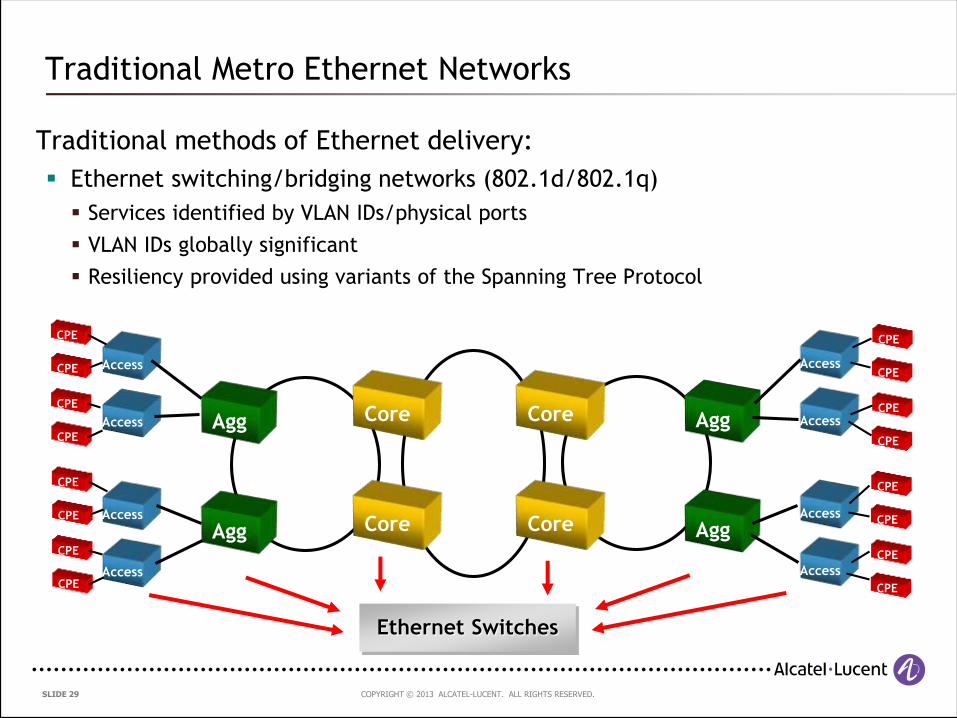
Traditional methods of Ethernet delivery:
Ethernet switching/bridging networks (802.1d/802.1q)
Services identified by VLAN IDs/physical ports
VLAN IDs globally significant
Resiliency provided using variants of the Spanning Tree Protocol
Traditional Metro Ethernet Networks
Agg
Agg
Core
Core
Access
Access
Access
Access
Agg
Agg
Access
Access
Access
Access
Core
Core
CPE
CPE
CPE
CPE
CPE
CPE
CPE
CPE
CPE
CPE
CPE
CPE
CPE
CPE
CPE
CPE
Ethernet Switches
COPYRIGHT © 2013 ALCATEL-LUCENT. ALL RIGHTS RESERVED. SLIDE 30
3.1 Service Identification
COPYRIGHT © 2013 ALCATEL-LUCENT. ALL RIGHTS RESERVED. SLIDE 31
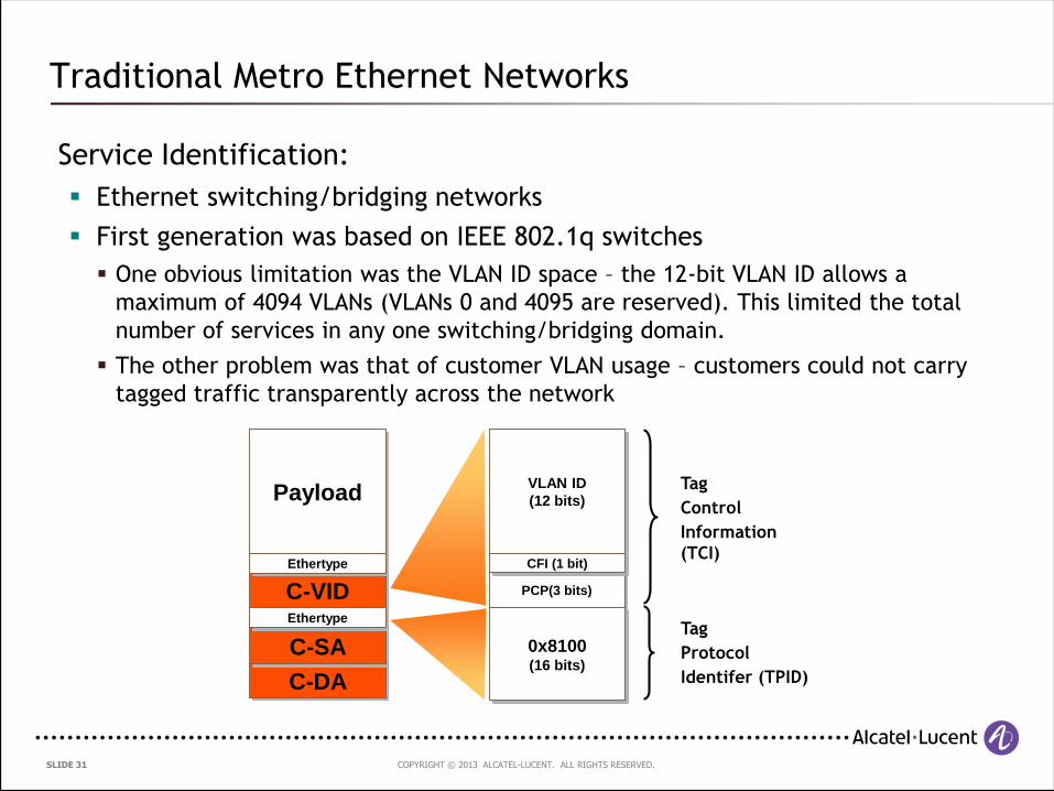
Service Identification:
Ethernet switching/bridging networks
First generation was based on IEEE 802.1q switches
One obvious limitation was the VLAN ID space – the 12-bit VLAN ID allows a
maximum of 4094 VLANs (VLANs 0 and 4095 are reserved). This limited the total
number of services in any one switching/bridging domain.
The other problem was that of customer VLAN usage – customers could not carry
tagged traffic transparently across the network
Traditional Metro Ethernet Networks
C-DA
C-SA
Payload
C-VIDEthertype
Ethertype
VLAN ID
(12 bits)
PCP(3 bits)
0x8100(16 bits)
CFI (1 bit)
Tag
Protocol
Identifer (TPID)
Tag
Control
Information
(TCI)
COPYRIGHT © 2013 ALCATEL-LUCENT. ALL RIGHTS RESERVED. SLIDE 32
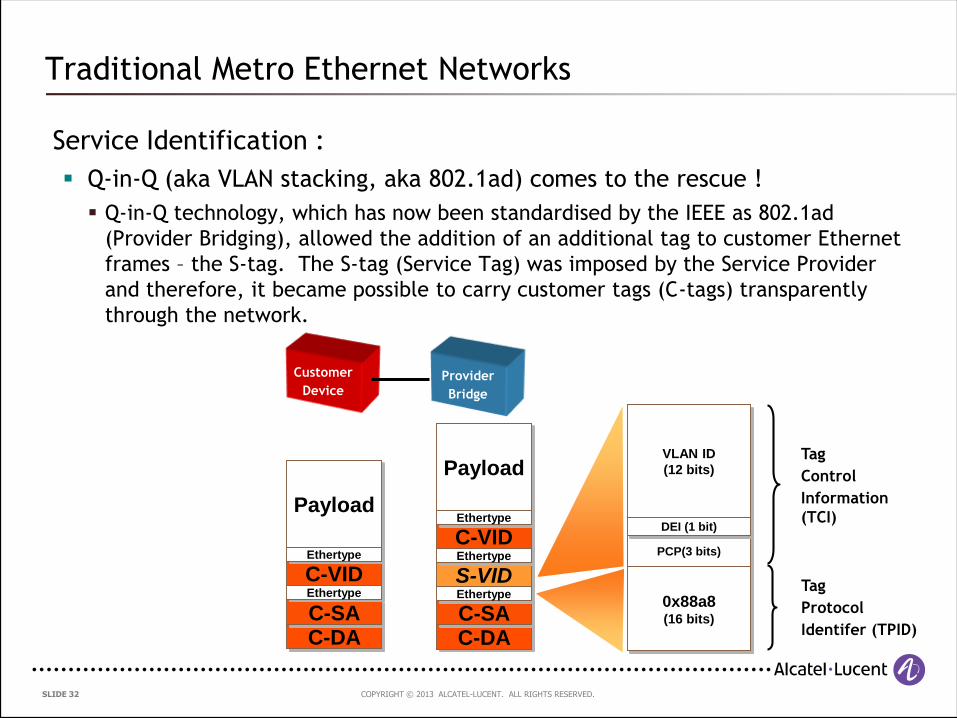
Service Identification :
Q-in-Q (aka VLAN stacking, aka 802.1ad) comes to the rescue !
Q-in-Q technology, which has now been standardised by the IEEE as 802.1ad
(Provider Bridging), allowed the addition of an additional tag to customer Ethernet
frames – the S-tag. The S-tag (Service Tag) was imposed by the Service Provider
and therefore, it became possible to carry customer tags (C-tags) transparently
through the network.
Traditional Metro Ethernet Networks
Provider
Bridge
Customer
Device
C-DAC-SA
Payload
C-VIDEthertype
Ethertype
C-DAC-SA
Payload
S-VID
C-VID
Ethertype
Ethertype
Ethertype
VLAN ID
(12 bits)
PCP(3 bits)
0x88a8(16 bits)
DEI (1 bit)
Tag
Protocol
Identifer (TPID)
Tag
Control
Information
(TCI)
COPYRIGHT © 2013 ALCATEL-LUCENT. ALL RIGHTS RESERVED. SLIDE 33
Service Identification:
Some important observations about Q-in-Q:
This is not a new encapsulation format; it simply results in the addition of a second
tag to the customer Ethernet frame, allowing any customer VLAN tags to be
preserved across the network
There is no change to the customer destination or source MAC addresses
The number of distinct service instances within each Provider Bridging domain is
still limited by the S-VLAN ID space i.e. 4094 S-VLANs. The difference is that
customer VLANs can now be preserved and carried transparently across the
provider network.
Traditional Metro Ethernet Networks
COPYRIGHT © 2013 ALCATEL-LUCENT. ALL RIGHTS RESERVED. SLIDE 34
3.2 Forwarding Mechanism
COPYRIGHT © 2013 ALCATEL-LUCENT. ALL RIGHTS RESERVED. SLIDE 35
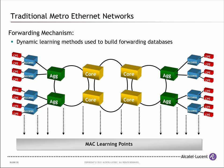
Forwarding Mechanism:
Dynamic learning methods used to build forwarding databases
Traditional Metro Ethernet Networks
Agg
Agg
Core
Core
Access
Access
Access
Access
Agg
Agg
Access
Access
Access
Access
Core
Core
CPE
CPE
CPE
CPE
CPE
CPE
CPE
CPE
CPE
CPE
CPE
CPE
CPE
CPE
CPE
CPE
MAC Learning Points
COPYRIGHT © 2013 ALCATEL-LUCENT. ALL RIGHTS RESERVED. SLIDE 36
Traditional Metro Ethernet Networks
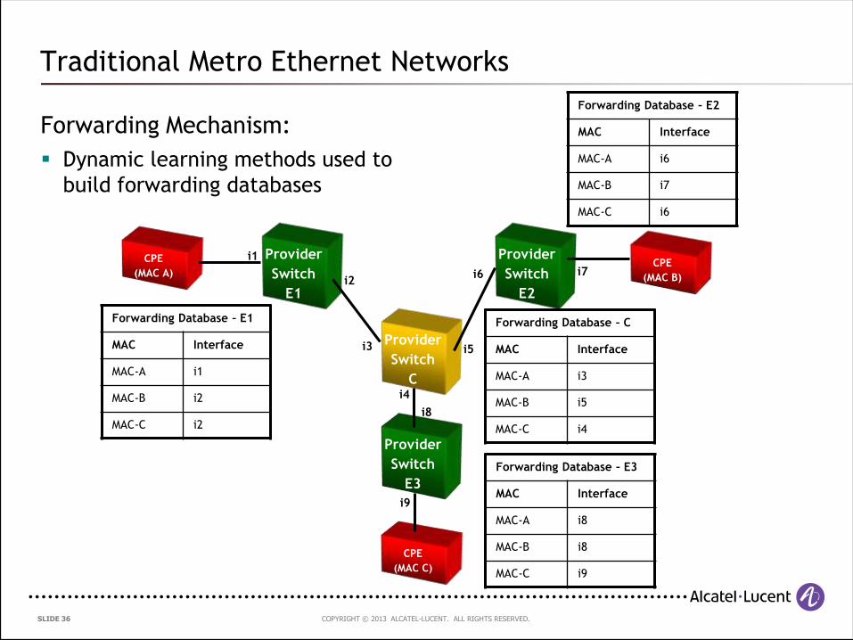
Forwarding Mechanism:
Dynamic learning methods used to
build forwarding databases
Provider
Switch
E1
CPE
(MAC A)
Provider
Switch
E2
Provider
Switch
C
Provider
Switch
E3
CPE
(MAC C)
CPE
(MAC B)
Forwarding Database – E1
MAC Interface
MAC-A i1
MAC-B i2
MAC-C i2
i1
i2
i3
i4
i5
i6 i7
i8
i9
Forwarding Database – E2
MAC Interface
MAC-A i6
MAC-B i7
MAC-C i6
Forwarding Database – E3
MAC Interface
MAC-A i8
MAC-B i8
MAC-C i9
Forwarding Database – C
MAC Interface
MAC-A i3
MAC-B i5
MAC-C i4
COPYRIGHT © 2013 ALCATEL-LUCENT. ALL RIGHTS RESERVED. SLIDE 37
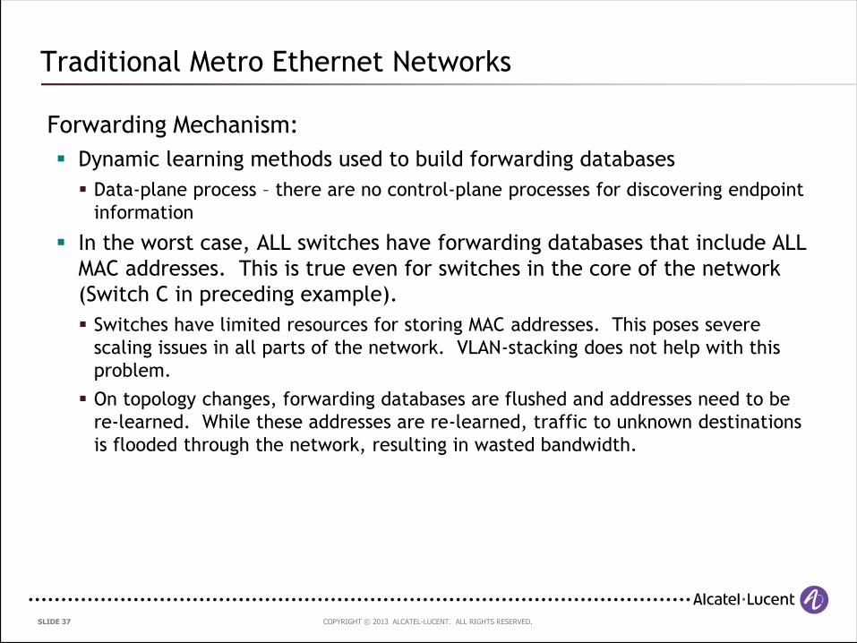
Forwarding Mechanism:
Dynamic learning methods used to build forwarding databases
Data-plane process – there are no control-plane processes for discovering endpoint
information
In the worst case, ALL switches have forwarding databases that include ALL
MAC addresses. This is true even for switches in the core of the network
(Switch C in preceding example).
Switches have limited resources for storing MAC addresses. This poses severe
scaling issues in all parts of the network. VLAN-stacking does not help with this
problem.
On topology changes, forwarding databases are flushed and addresses need to be
re-learned. While these addresses are re-learned, traffic to unknown destinations
is flooded through the network, resulting in wasted bandwidth.
Traditional Metro Ethernet Networks
COPYRIGHT © 2013 ALCATEL-LUCENT. ALL RIGHTS RESERVED. SLIDE 38
3.3 Resiliency and Redundancy
COPYRIGHT © 2013 ALCATEL-LUCENT. ALL RIGHTS RESERVED. SLIDE 39
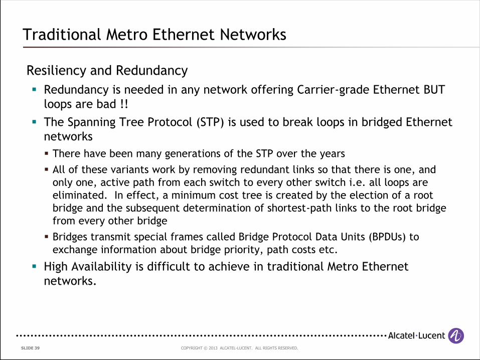
Resiliency and Redundancy
Redundancy is needed in any network offering Carrier-grade Ethernet BUT
loops are bad !!
The Spanning Tree Protocol (STP) is used to break loops in bridged Ethernet
networks
There have been many generations of the STP over the years
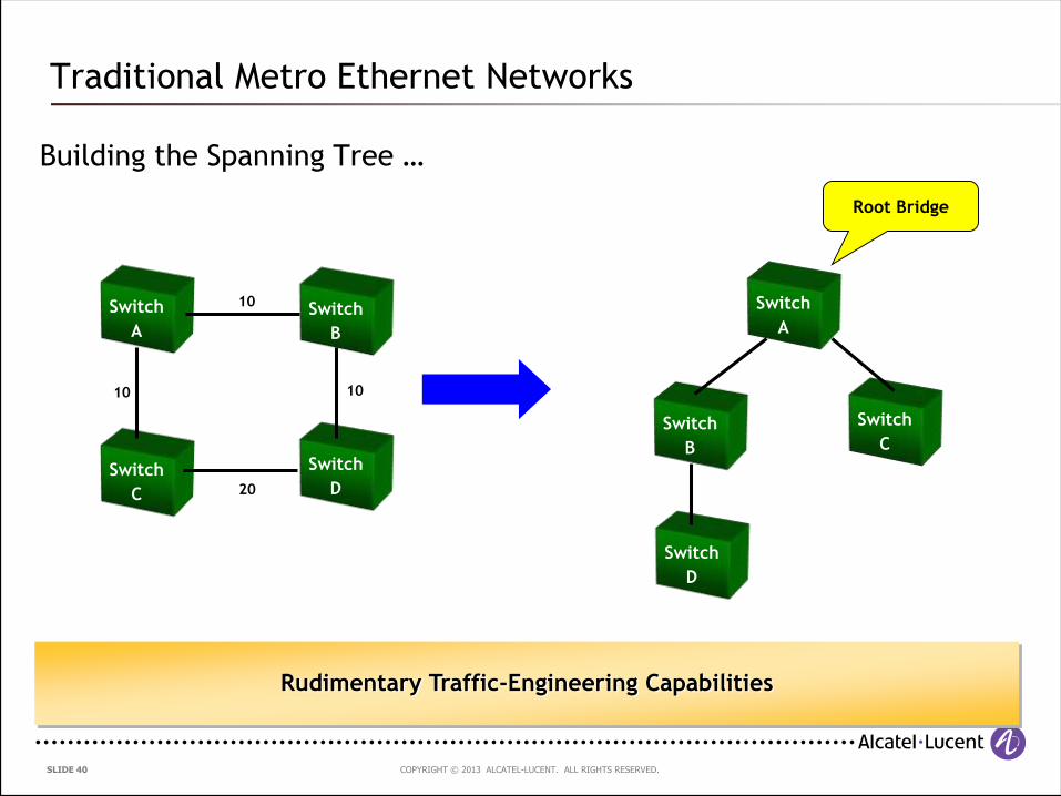
All of these variants work by removing redundant links so that there is one, and
only one, active path from each switch to every other switch i.e. all loops are
eliminated. In effect, a minimum cost tree is created by the election of a root
bridge and the subsequent determination of shortest-path links to the root bridge
from every other bridge
Bridges transmit special frames called Bridge Protocol Data Units (BPDUs) to
exchange information about bridge priority, path costs etc.
High Availability is difficult to achieve in traditional Metro Ethernet
networks.
Traditional Metro Ethernet Networks
COPYRIGHT © 2013 ALCATEL-LUCENT. ALL RIGHTS RESERVED. SLIDE 40
Building the Spanning Tree …
Traditional Metro Ethernet Networks
Switch
A
Switch
B
Switch
C
Switch
D
10
10
20
10
Switch
A
Switch
B
Switch
C
Switch
D
Root Bridge
Rudimentary Traffic-Engineering Capabilities
COPYRIGHT © 2013 ALCATEL-LUCENT. ALL RIGHTS RESERVED. SLIDE 41
First generation of STP (IEEE802.1d-1998):
Had a number of significant shortcomings:
Convergence times – the protocol is timer-based with times in the order of 10s of
seconds. After network topology changes (failure or addition of links), it could
take up to 50s for the network to re-converge
The protocol was VLAN-unaware, which meant that in an IEEE 802.1q network, all
VLANs had to share the same spanning tree. This meant that there were network
links that would not be utilised at all since they were placed into a blocked state.
– Many vendors implemented their own, proprietary extensions to the protocol to
allow the use of a separate STP instance per VLAN, allowing better link utilisation
within the network
There were many conditions which resulted in the inadvertent formation of loops in
the network. Given the flooding nature of bridged Ethernet, and the lack of a TTL-
like field in Ethernet frames, looping frames could loop forever.
– There are numerous well-publicised instances of network meltdowns in Enterprise
and Service Provider networks
– A lot of service providers have been permanently scarred by the catastrophic effects
of STP loops !
Traditional Metro Ethernet Networks
COPYRIGHT © 2013 ALCATEL-LUCENT. ALL RIGHTS RESERVED. SLIDE 42
Newer generations of STP (IEEE802.1d-2004 – Rapid STP aka 802.1w):
Some major improvements:
Dependence on timers is reduced. Negotiation protocols have been introduced to
allow rapid transitioning of links to a forwarding state
The Topology Change process has been re-designed to allow faster recovery from
topology changes
Optimisations for certain types of direct and indirect link failures
Convergence times are now down to sub-second in certain special cases but a lot of
failure cases still require seconds to converge !
But…
The protocol was still VLAN-unaware, which meant that the issue of under-utilised
links was still present
Traditional Metro Ethernet Networks
COPYRIGHT © 2013 ALCATEL-LUCENT. ALL RIGHTS RESERVED. SLIDE 43
Newer generations of STP (IEEE802.1q-2003 – Multiple STP aka 802.1s):
Built on top of RSTP
Added VLAN awareness:
Introduces the capability for the existence of multiple STP instances within the
same bridged network
Allows the association of VLANs to STP instances, in order to provide a (relatively)
small number of STP instances, instead of using an instance per VLAN.
Different STP instances can have different topologies, which allows much better
link utilisation
BUT
The stigma associated with past failures is hard to remove…
The protocol is fairly complicated, compared to its much simpler predecessors
Traditional Metro Ethernet Networks
COPYRIGHT © 2013 ALCATEL-LUCENT. ALL RIGHTS RESERVED. SLIDE 44
3.4 Recent Developments
COPYRIGHT © 2013 ALCATEL-LUCENT. ALL RIGHTS RESERVED. SLIDE 45
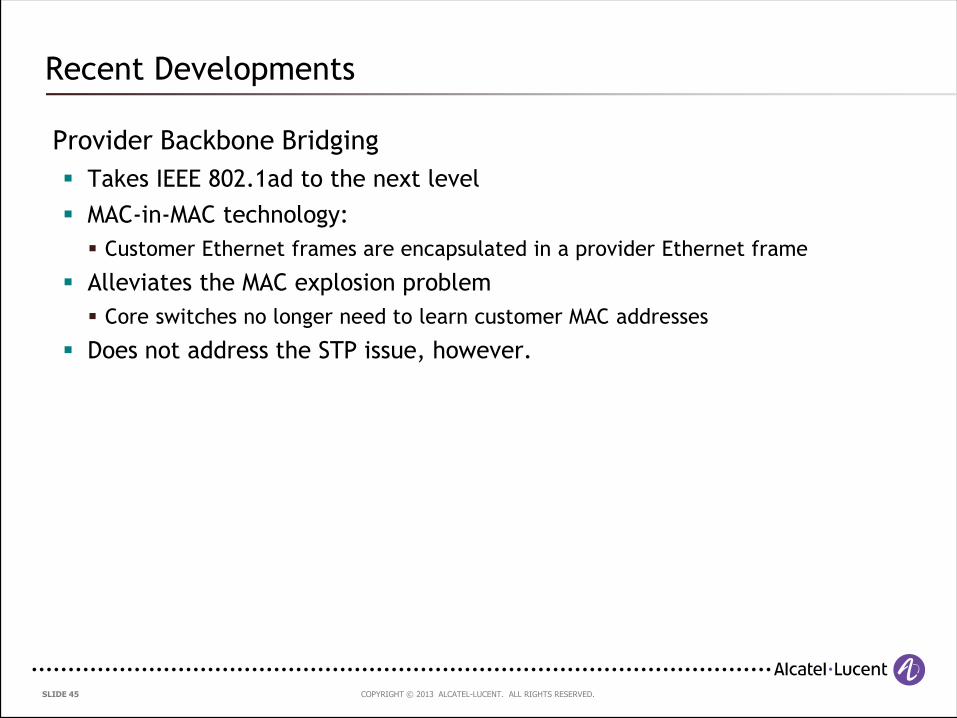
Provider Backbone Bridging
Takes IEEE 802.1ad to the next level
MAC-in-MAC technology:
Customer Ethernet frames are encapsulated in a provider Ethernet frame
Alleviates the MAC explosion problem
Core switches no longer need to learn customer MAC addresses
Does not address the STP issue, however.
Recent Developments
COPYRIGHT © 2013 ALCATEL-LUCENT. ALL RIGHTS RESERVED. SLIDE 46
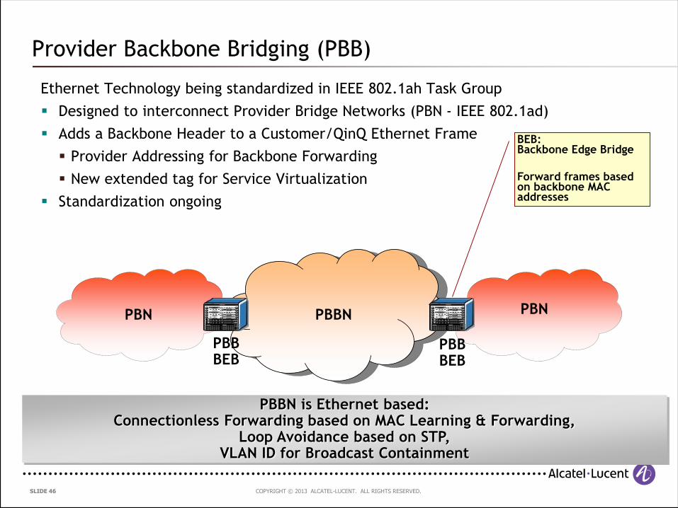
Provider Backbone Bridging (PBB)
Ethernet Technology being standardized in IEEE 802.1ah Task Group
Designed to interconnect Provider Bridge Networks (PBN - IEEE 802.1ad)
Adds a Backbone Header to a Customer/QinQ Ethernet Frame
Provider Addressing for Backbone Forwarding
New extended tag for Service Virtualization
Standardization ongoing
PBBN is Ethernet based:Connectionless Forwarding based on MAC Learning & Forwarding,
Loop Avoidance based on STP,VLAN ID for Broadcast Containment
PBN PBNPBBN
PBB BEB
PBB BEB
BEB:Backbone Edge Bridge
Forward frames based on backbone MAC addresses
COPYRIGHT © 2013 ALCATEL-LUCENT. ALL RIGHTS RESERVED. SLIDE 47
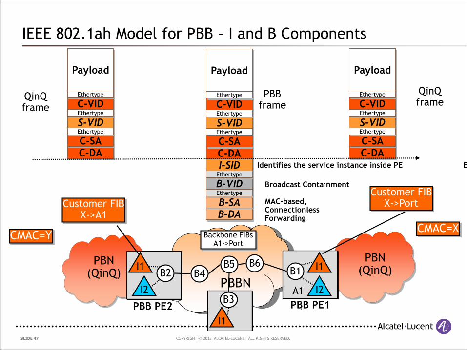
C-DAC-SA
Payload
B-DAB-SA
B-VID
I-SID
S-VID
C-VID
Ethertype
Ethertype
Ethertype
Ethertype
Ethertype
PBN (QinQ)
PBN (QinQ)
PBBN
PBB PE2
C-DAC-SA
Payload
S-VID
C-VID
Ethertype
Ethertype
Ethertype
C-DAC-SA
Payload
S-VID
C-VID
Ethertype
Ethertype
EthertypeQinQ frame
QinQ frame
PBB frame
B2
PBB PE1
B1B4B6B5
B3A1
CMAC=XBackbone FIBs
A1->Port
Customer FIBX->A1
Customer FIBX->Port
CMAC=Y
MAC-based, Connectionless Forwarding
Broadcast Containment
Extended Service TagIdentifies the service instance inside PE
I1
I2
I1
I1
I2
IEEE 802.1ah Model for PBB – I and B Components
COPYRIGHT © 2013 ALCATEL-LUCENT. ALL RIGHTS RESERVED. SLIDE 48
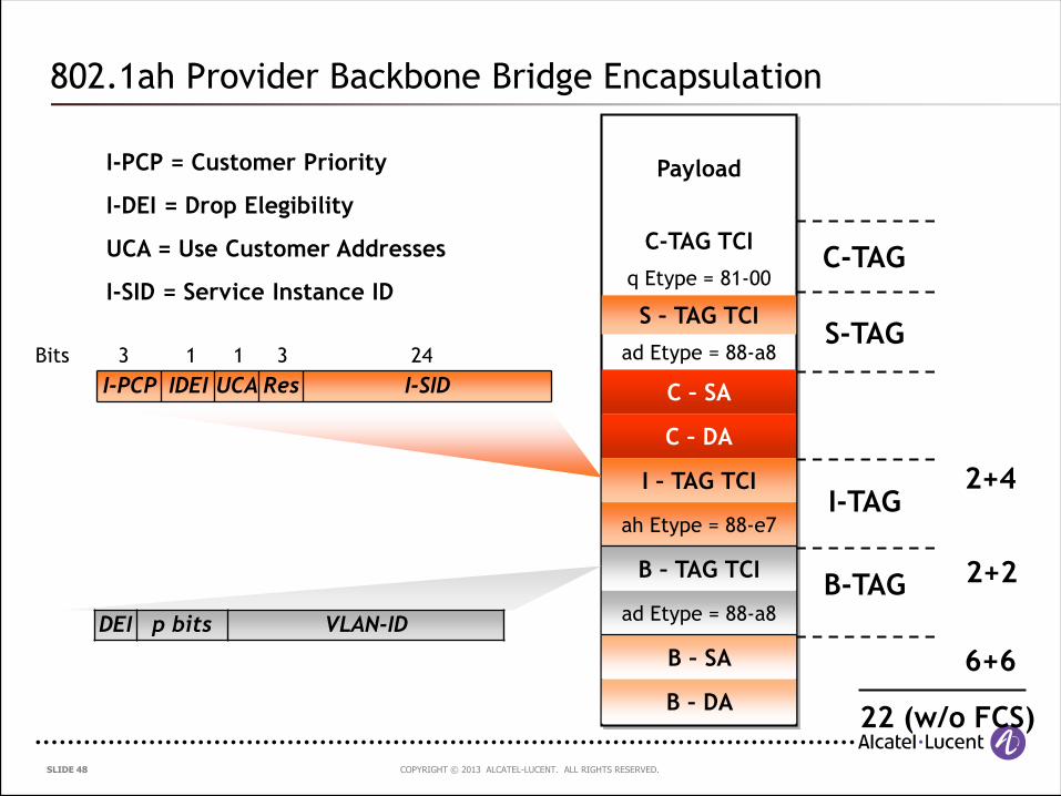
802.1ah Provider Backbone Bridge Encapsulation
Payload
C-TAG TCI
q Etype = 81-00
S – TAG TCI
ad Etype = 88-a8
C – SA
C – DA
I – TAG TCI
ah Etype = 88-e7
B – TAG TCI
ad Etype = 88-a8
B – SA
B – DA
6+6
22 (w/o FCS)
2+2
2+4I-TAG
B-TAG
S-TAG
C-TAG
DEI p bits VLAN-ID
I-PCP IDEI UCA Res I-SID
24313 1Bits
I-PCP = Customer Priority
I-DEI = Drop Elegibility
UCA = Use Customer Addresses
I-SID = Service Instance ID
COPYRIGHT © 2013 ALCATEL-LUCENT. ALL RIGHTS RESERVED. SLIDE 49
Shortest Path Bridging
Addresses the STP issue…
SPBM is a Spanning-Tree Protocol replacement for PBB
Being standardized in the IEEE in 802.1aq
Shortest path backbone bridging Mac/VLAN Mode
Requirements to address:
No blocked ports like STP
Fast resiliency
No hop count restrictions like STP
Simple networking paradigm
Recent Developments
COPYRIGHT © 2013 ALCATEL-LUCENT. ALL RIGHTS RESERVED. SLIDE 50
How it works:
Discover the network topology
Enable a routing protocol on each system to discover the network topology
Build shortest path trees between the network nodes
To be used later for forwarding traffic on
Distribute the service information to the network nodes
Once services are created (i.e. ISIDs), the routing protocol is used to distribute the
information to all SPBM nodes
All nodes (edge and core) are now aware of all VPNs and where the endpoints are.
Update Forwarding Tables to connect the service nodes
If the node determines that it is on the shortest path between endpoints for an
ISID, it updates its FIB for forwarding.
When all nodes on shortest path complete the calculations, the VPN is connected!
Shortest Path Bridging
COPYRIGHT © 2013 ALCATEL-LUCENT. ALL RIGHTS RESERVED. SLIDE 51
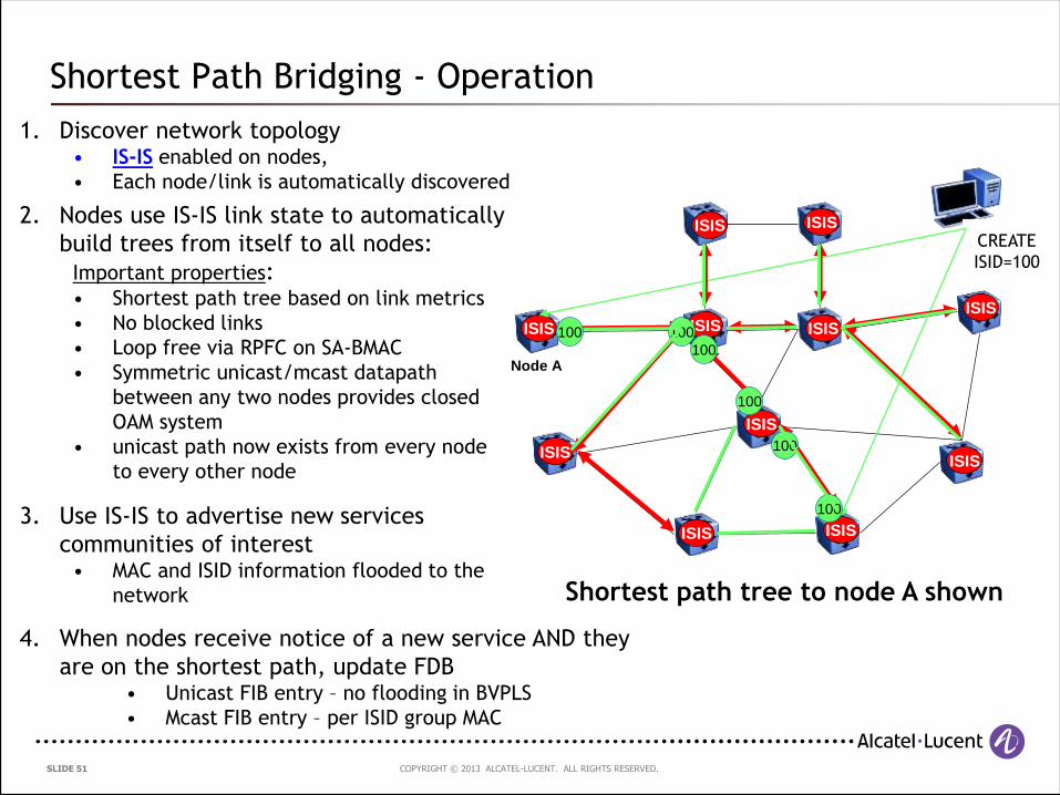
1. Discover network topology• IS-IS enabled on nodes,
• Each node/link is automatically discovered
ISIS
ISIS ISIS
ISISISIS
ISIS
ISIS
ISIS ISIS
ISIS
ISIS
2. Nodes use IS-IS link state to automatically
build trees from itself to all nodes:
Important properties:• Shortest path tree based on link metrics
• No blocked links
• Loop free via RPFC on SA-BMAC
• Symmetric unicast/mcast datapath
between any two nodes provides closed
OAM system
• unicast path now exists from every node
to every other node
3. Use IS-IS to advertise new services
communities of interest• MAC and ISID information flooded to the
network
CREATE
ISID=100
4. When nodes receive notice of a new service AND they
are on the shortest path, update FDB• Unicast FIB entry – no flooding in BVPLS
• Mcast FIB entry – per ISID group MAC
100
100
100
100
100
100
Shortest path tree to node A shown
Node A
Shortest Path Bridging - Operation
COPYRIGHT © 2013 ALCATEL-LUCENT. ALL RIGHTS RESERVED. SLIDE 52
2
43
1
2
43
12
43 1
3
2
1
4
4
2
1
3
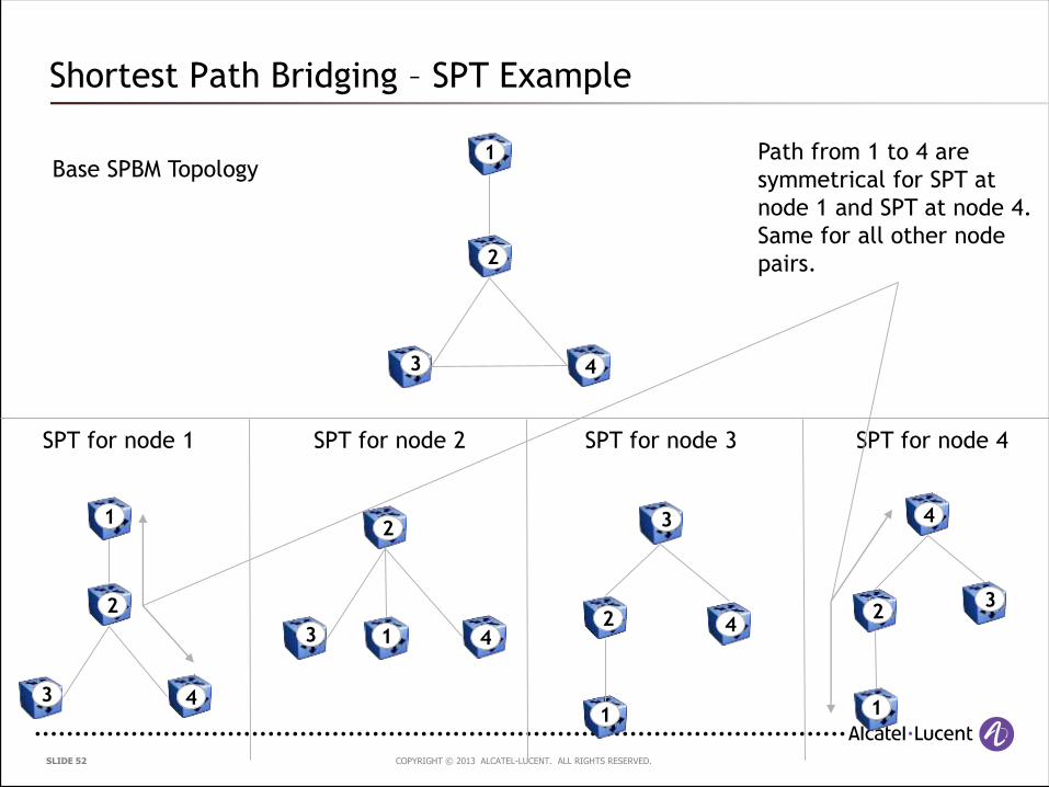
Base SPBM Topology
SPT for node 1 SPT for node 2 SPT for node 3 SPT for node 4
Path from 1 to 4 are
symmetrical for SPT at
node 1 and SPT at node 4.
Same for all other node
pairs.
Shortest Path Bridging – SPT Example

COPYRIGHT © 2013 ALCATEL-LUCENT. ALL RIGHTS RESERVED. SLIDE 53
3.5 Summary
COPYRIGHT © 2013 ALCATEL-LUCENT. ALL RIGHTS RESERVED. SLIDE 54
Summary of Issues:
High Availability is difficult to achieve in networks running the Spanning
Tree Protocol
Scalability – IEEE 802.1q/802.1ad networks run into scalability limitations in
terms of the number of supported services
Customer Ethernet frames are encapsulated in a provider Ethernet frame
QoS – only very rudimentary traffic-engineering can be achieved in bridged
Ethernet networks.
A lot of deployed Ethernet switching platforms lack carrier-class capabilities
required for the delivery of Carrier Ethernet services
New extensions in IEEE 802.1ah address some limitations such as the
number of service instances and MAC explosion problems
New extensions in IEEE 802.1aq address the replacement of the Spanning
Tree Protocol
Traditional Metro Ethernet Networks
COPYRIGHT © 2013 ALCATEL-LUCENT. ALL RIGHTS RESERVED. SLIDE 55
Which IEEE standard defines Provider Bridging (Q-in-Q) ?
Audience Question 2
COPYRIGHT © 2013 ALCATEL-LUCENT. ALL RIGHTS RESERVED. SLIDE 56
What is the size of the I-SID field in IEEE 802.1ah?
Audience Question 3
COPYRIGHT © 2013 ALCATEL-LUCENT. ALL RIGHTS RESERVED. SLIDE 57
4. Delivering Ethernet over MPLS
COPYRIGHT © 2013 ALCATEL-LUCENT. ALL RIGHTS RESERVED. SLIDE 58
Agenda
4. Delivering Ethernet over MPLS
4.1 Introduction to MPLS
4.2 The Pseudowire Reference Model
4.3 Ethernet Virtual Private Wire Service
4.4 Ethernet Virtual Private LAN Service
4.5 Scaling VPLS
4.6 VPLS Topologies
4.7 Resiliency Mechanisms
COPYRIGHT © 2013 ALCATEL-LUCENT. ALL RIGHTS RESERVED. SLIDE 59
4.1 Introduction to MPLS
COPYRIGHT © 2013 ALCATEL-LUCENT. ALL RIGHTS RESERVED. SLIDE 60
MPLS Attributes
Convergence: From “MPLS over everything” to “Everything over MPLS” !
One network, multiple services
Excellent virtualisation capabilities
Today’s MPLS network can transport IP, ATM, Frame Relay and even TDM !
Scalability
MPLS is used in some of the largest service provider networks in the world
Advanced Traffic Engineering capabilities using RSVP-TE
Rapid recovery based on MPLS Fast ReRoute (FRR)
Rapid restoration around failures by local action at the Points of Local Repair (PLRs)
Sub-50ms restoration on link/node failures is a key requirement for carriers who are used to such performance in their SONET/SDH networks
Feature-richness
MPLS has 10 years of development behind it and continues to evolve today
Layer 3 VPNs have already proven themselves as the killer app for MPLS – there is no reason why this success cannot be emulated by Layer 2 VPNs
Delivering Ethernet over MPLS
COPYRIGHT © 2013 ALCATEL-LUCENT. ALL RIGHTS RESERVED. SLIDE 61
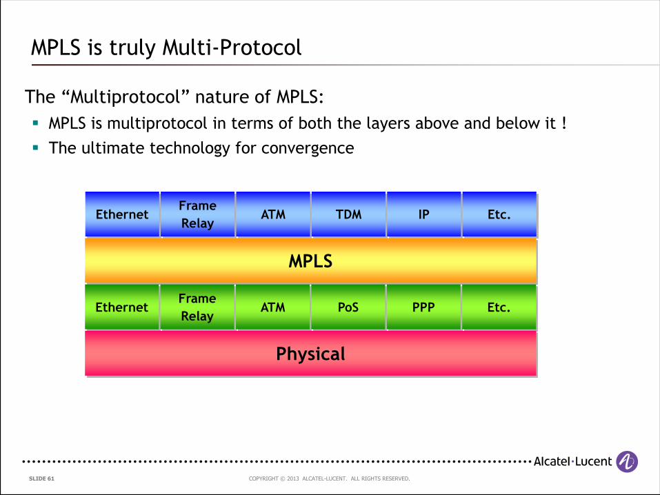
The “Multiprotocol” nature of MPLS:
MPLS is multiprotocol in terms of both the layers above and below it !
The ultimate technology for convergence
MPLS is truly Multi-Protocol
MPLS
EthernetFrame
RelayATM PoS PPP Etc.
Physical
EthernetFrame
RelayATM TDM IP Etc.
COPYRIGHT © 2013 ALCATEL-LUCENT. ALL RIGHTS RESERVED. SLIDE 62
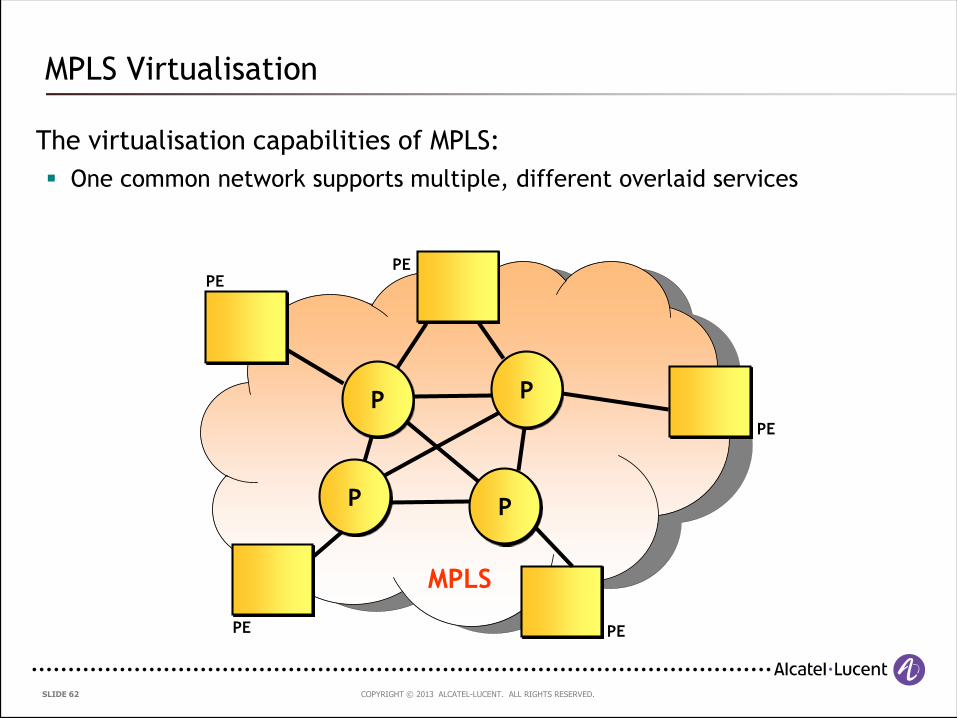
The virtualisation capabilities of MPLS:
One common network supports multiple, different overlaid services
MPLS Virtualisation
PE PE
MPLS
PE
PE
PE
P
P P
P
COPYRIGHT © 2013 ALCATEL-LUCENT. ALL RIGHTS RESERVED. SLIDE 63
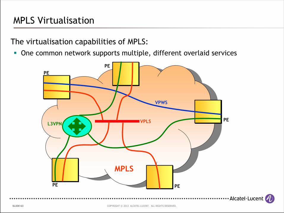
The virtualisation capabilities of MPLS:
One common network supports multiple, different overlaid services
MPLS Virtualisation
VPLS
VPWS
L3VPN
MPLS
PE
PE PE
PE
PE
COPYRIGHT © 2013 ALCATEL-LUCENT. ALL RIGHTS RESERVED. SLIDE 6464 | MPLS-based Metro Ethernet Networks, February 2011
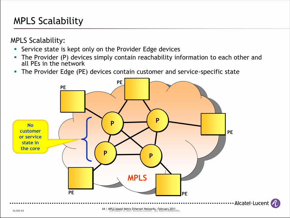
MPLS Scalability: Service state is kept only on the Provider Edge devices
The Provider (P) devices simply contain reachability information to each other and all PEs in the network
The Provider Edge (PE) devices contain customer and service-specific state
MPLS Scalability
PE PE
MPLS
PE
PE
PE
P
P P
PNo
customer
or service
state in
the core
COPYRIGHT © 2013 ALCATEL-LUCENT. ALL RIGHTS RESERVED. SLIDE 65
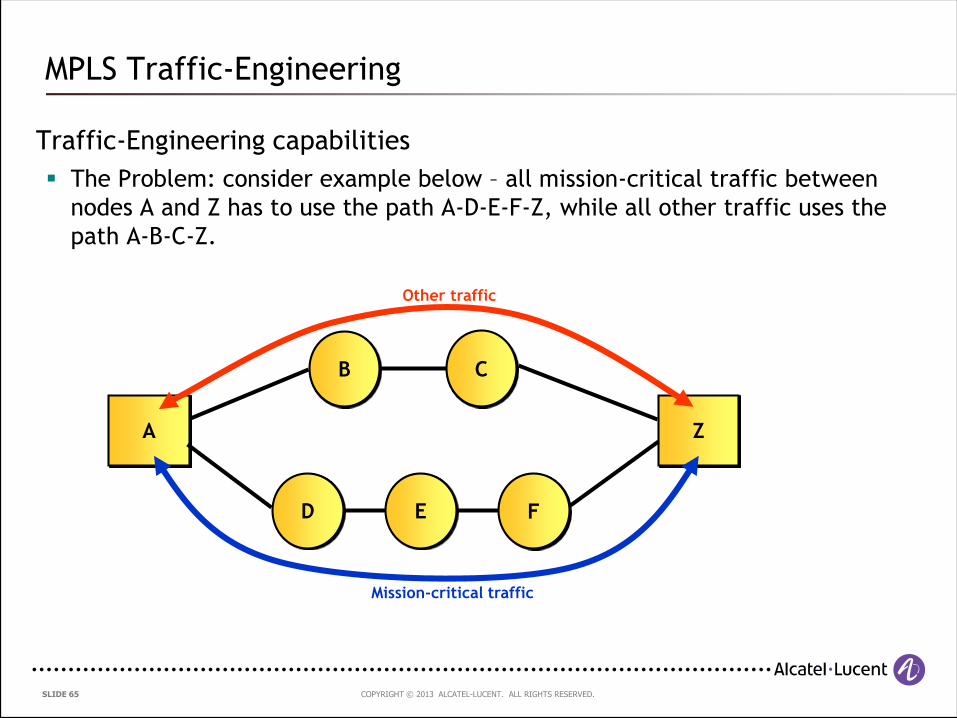
Traffic-Engineering capabilities
The Problem: consider example below – all mission-critical traffic between
nodes A and Z has to use the path A-D-E-F-Z, while all other traffic uses the
path A-B-C-Z.
MPLS Traffic-Engineering
A Z
D E F
B C
Other traffic
Mission-critical traffic
COPYRIGHT © 2013 ALCATEL-LUCENT. ALL RIGHTS RESERVED. SLIDE 66
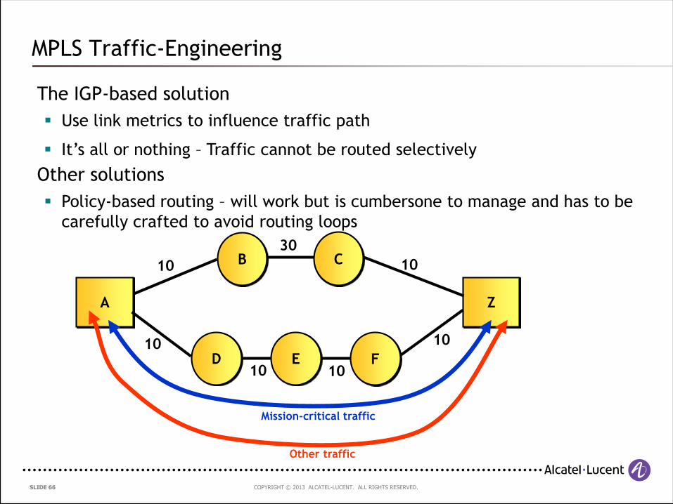
The IGP-based solution
Use link metrics to influence traffic path
MPLS Traffic-Engineering
A Z
D E F
B C10
10
10 10
30
10
10
Other traffic
Mission-critical traffic
It’s all or nothing – Traffic cannot be routed selectively
Other solutions
Policy-based routing – will work but is cumbersone to manage and has to be
carefully crafted to avoid routing loops
COPYRIGHT © 2013 ALCATEL-LUCENT. ALL RIGHTS RESERVED. SLIDE 67
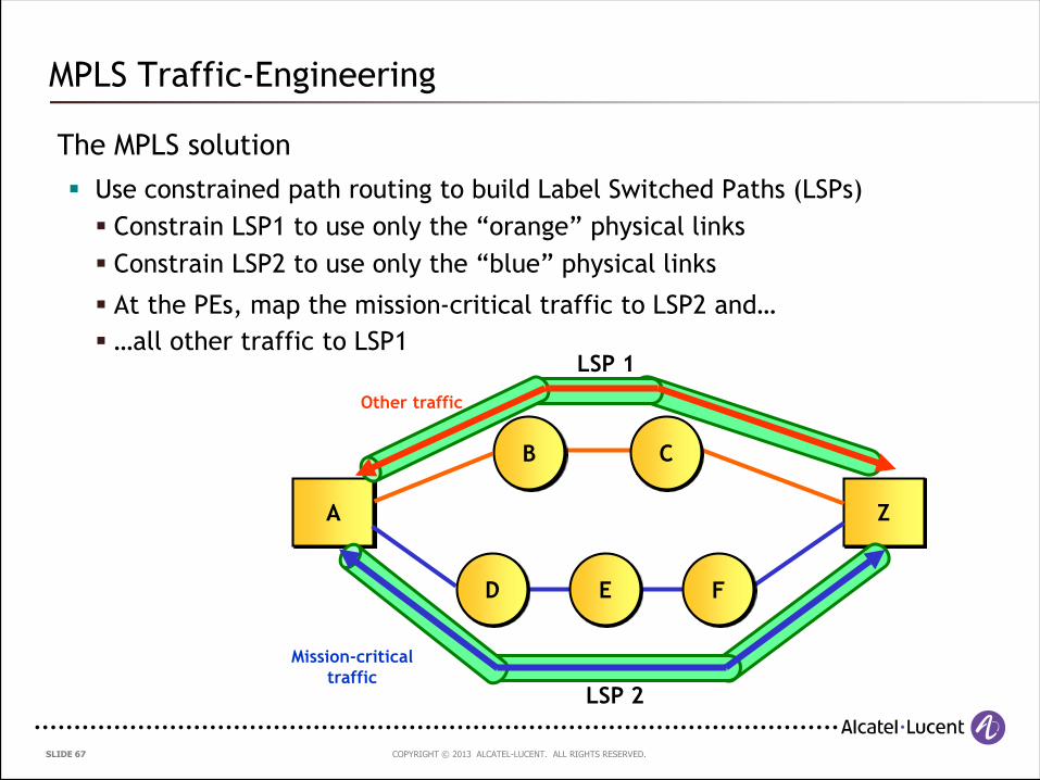
The MPLS solution
Use constrained path routing to build Label Switched Paths (LSPs)
MPLS Traffic-Engineering
Constrain LSP1 to use only the “orange” physical links
A Z
D E F
B C
Mission-critical
trafficLSP 2
LSP 1
Other traffic
Constrain LSP2 to use only the “blue” physical links
At the PEs, map the mission-critical traffic to LSP2 and…
…all other traffic to LSP1
COPYRIGHT © 2013 ALCATEL-LUCENT. ALL RIGHTS RESERVED. SLIDE 68
Recovery from failures – typical IGP
Step 1 – Detection of the failure
One or more routers detect that a failure (link or node) has occurred
Step 2 – Propagation of failure notification
The router(s) detecting the failure inform other routers in the domain about the
failure
Step 3 – Recomputation of Paths/Routes
All routers which receive the failure notification now have to recalculate new
routes/paths by running SPF algorithms etc
Step 4 – Updating of the Forwarding Table
Once new routes are computed, they are downloaded to the routers’ forwarding
table, in order to allow them to be used
All of this takes time…
MPLS Traffic-Engineering
COPYRIGHT © 2013 ALCATEL-LUCENT. ALL RIGHTS RESERVED. SLIDE 69
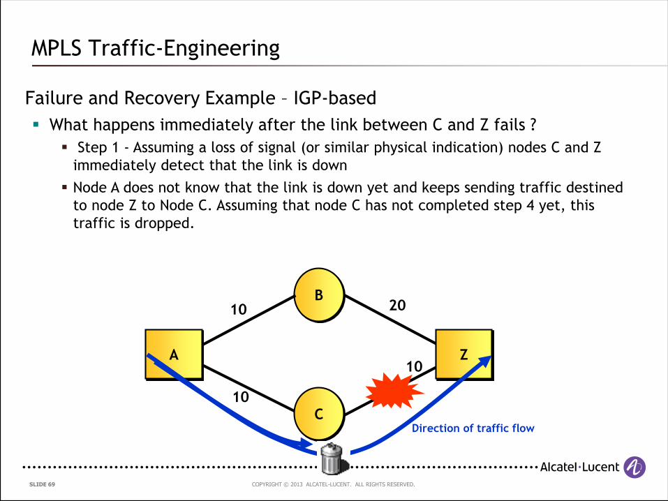
Failure and Recovery Example – IGP-based
What happens immediately after the link between C and Z fails ?
MPLS Traffic-Engineering
B
Z
Direction of traffic flow
Step 1 - Assuming a loss of signal (or similar physical indication) nodes C and Z
immediately detect that the link is down
Node A does not know that the link is down yet and keeps sending traffic destined
to node Z to Node C. Assuming that node C has not completed step 4 yet, this
traffic is dropped.
C
A
10
10
20
10
COPYRIGHT © 2013 ALCATEL-LUCENT. ALL RIGHTS RESERVED. SLIDE 70
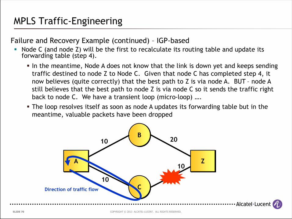
Failure and Recovery Example (continued) – IGP-based Node C (and node Z) will be the first to recalculate its routing table and update its
forwarding table (step 4).
MPLS Traffic-Engineering
In the meantime, Node A does not know that the link is down yet and keeps sending
traffic destined to node Z to Node C. Given that node C has completed step 4, it
now believes (quite correctly) that the best path to Z is via node A. BUT – node A
still believes that the best path to node Z is via node C so it sends the traffic right
back to node C. We have a transient loop (micro-loop) ….
The loop resolves itself as soon as node A updates its forwarding table but in the
meantime, valuable packets have been dropped
B
Z
Direction of traffic flow C
A
10
10
20
10
COPYRIGHT © 2013 ALCATEL-LUCENT. ALL RIGHTS RESERVED. SLIDE 71
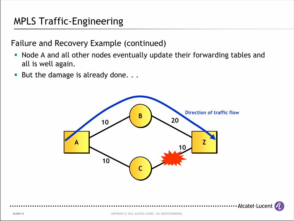
Failure and Recovery Example (continued)
Node A and all other nodes eventually update their forwarding tables and
all is well again.
But the damage is already done. . .
MPLS Traffic-Engineering
B
Z
Direction of traffic flow
C
A
10
10
20
10
COPYRIGHT © 2013 ALCATEL-LUCENT. ALL RIGHTS RESERVED. SLIDE 72
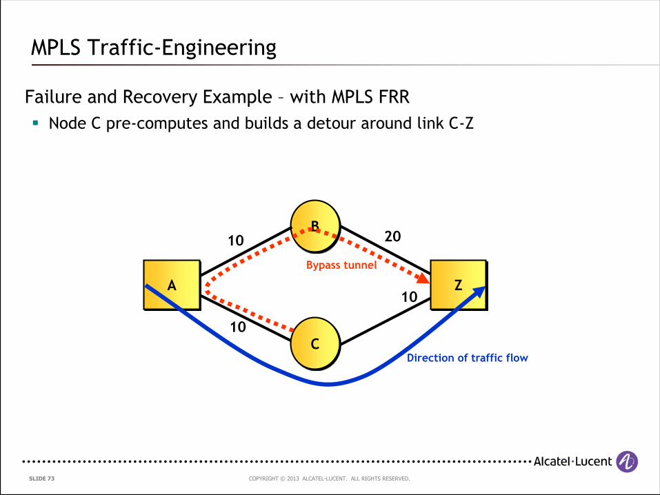
Recovery from failures – how can MPLS help ?
RSVP-TE Fast Re-Route (FRR) pre-computes detours around potential failure
points such as next-hop nodes and links
When link or node failures occur, the routers (Points of Local Repair)
directly connected to the failed link rapidly (sub-50ms) switch all traffic
onto the detour paths.
The network eventually converges and the head-end router (source of the
traffic) switches traffic onto the most optimal path. Until that is done,
traffic flows over the potentially sub-optimal detour path BUT the packet
loss is kept to a minimum
MPLS Traffic-Engineering
COPYRIGHT © 2013 ALCATEL-LUCENT. ALL RIGHTS RESERVED. SLIDE 73
Failure and Recovery Example – with MPLS FRR
Node C pre-computes and builds a detour around link C-Z
MPLS Traffic-Engineering
B
Z
Direction of traffic flowC
A
10
10
20
10
Bypass tunnel
COPYRIGHT © 2013 ALCATEL-LUCENT. ALL RIGHTS RESERVED. SLIDE 74
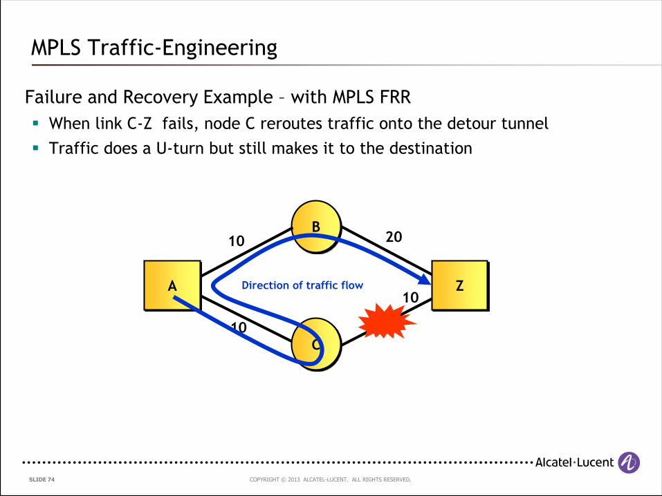
Failure and Recovery Example – with MPLS FRR
When link C-Z fails, node C reroutes traffic onto the detour tunnel
Traffic does a U-turn but still makes it to the destination
MPLS Traffic-Engineering
B
ZDirection of traffic flow
C
A
10
10
20
10
COPYRIGHT © 2013 ALCATEL-LUCENT. ALL RIGHTS RESERVED. SLIDE 75
What is the size of the MPLS label stack entry ?
And the MPLS label itself ?
Audience Question 4
COPYRIGHT © 2013 ALCATEL-LUCENT. ALL RIGHTS RESERVED. SLIDE 76
4.2 The Pseudowire Reference Model
COPYRIGHT © 2013 ALCATEL-LUCENT. ALL RIGHTS RESERVED. SLIDE 77
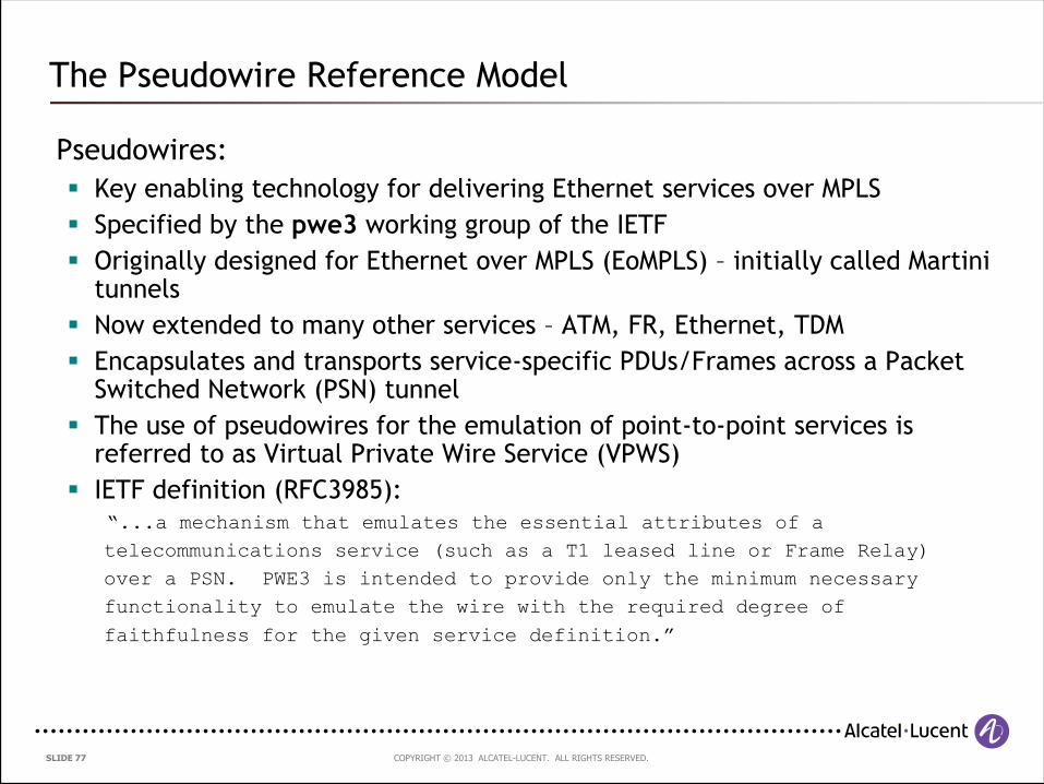
Pseudowires:
Key enabling technology for delivering Ethernet services over MPLS
Specified by the pwe3 working group of the IETF
Originally designed for Ethernet over MPLS (EoMPLS) – initially called Martini tunnels
Now extended to many other services – ATM, FR, Ethernet, TDM
Encapsulates and transports service-specific PDUs/Frames across a Packet Switched Network (PSN) tunnel
The use of pseudowires for the emulation of point-to-point services is referred to as Virtual Private Wire Service (VPWS)
IETF definition (RFC3985):“...a mechanism that emulates the essential attributes of a
telecommunications service (such as a T1 leased line or Frame Relay)
over a PSN. PWE3 is intended to provide only the minimum necessary
functionality to emulate the wire with the required degree of
faithfulness for the given service definition.”
The Pseudowire Reference Model
COPYRIGHT © 2013 ALCATEL-LUCENT. ALL RIGHTS RESERVED. SLIDE 78
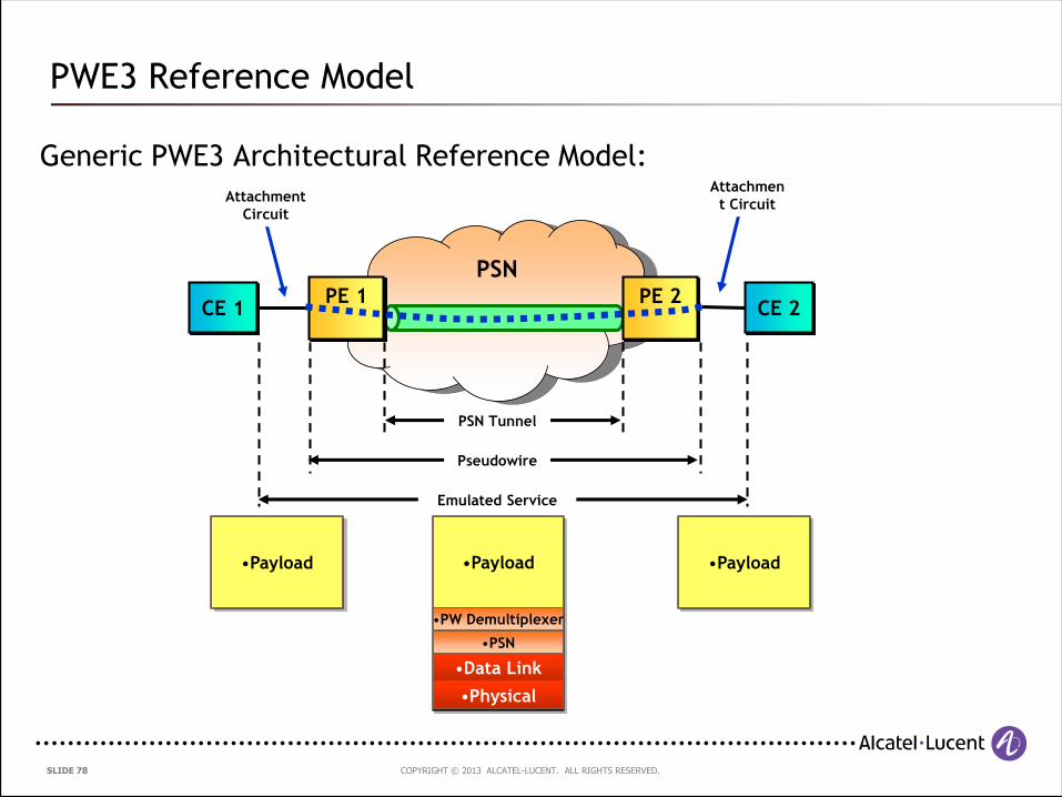
Generic PWE3 Architectural Reference Model:
PWE3 Reference Model
PSN
CE 1 CE 2
Emulated Service
Pseudowire
PSN Tunnel
Attachment
Circuit
Attachmen
t Circuit
PE 1 PE 2
•Payload •Payload
•PW Demultiplexer
•Physical
•Data Link
•PSN
•Payload
COPYRIGHT © 2013 ALCATEL-LUCENT. ALL RIGHTS RESERVED. SLIDE 79
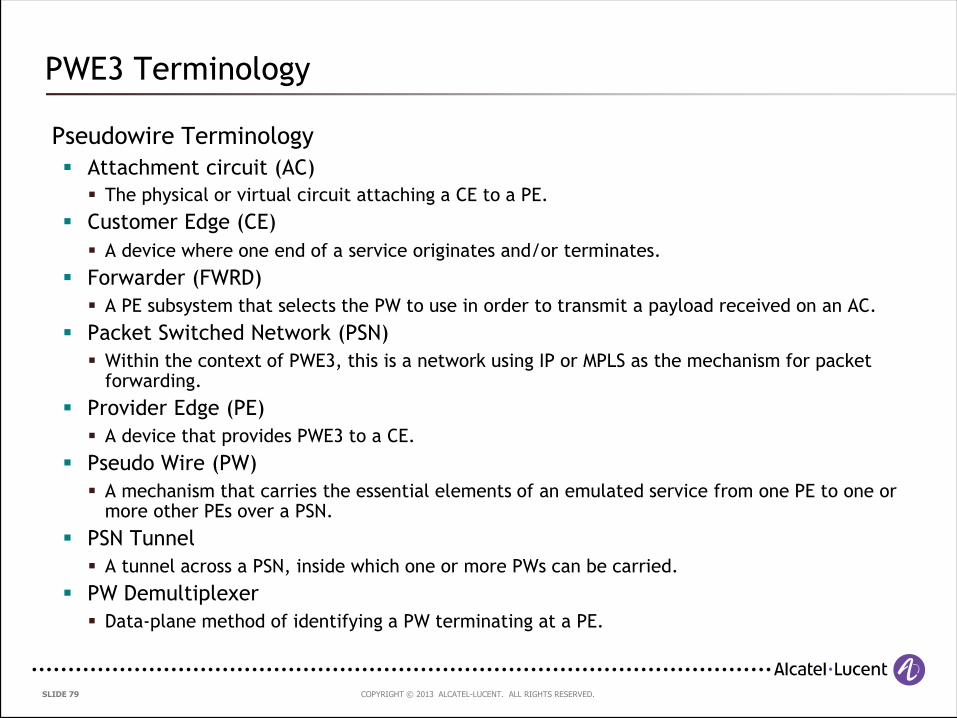
Pseudowire Terminology
Attachment circuit (AC)
The physical or virtual circuit attaching a CE to a PE.
Customer Edge (CE)
A device where one end of a service originates and/or terminates.
Forwarder (FWRD)
A PE subsystem that selects the PW to use in order to transmit a payload received on an AC.
Packet Switched Network (PSN)
Within the context of PWE3, this is a network using IP or MPLS as the mechanism for packet forwarding.
Provider Edge (PE)
A device that provides PWE3 to a CE.
Pseudo Wire (PW)
A mechanism that carries the essential elements of an emulated service from one PE to one or more other PEs over a PSN.
PSN Tunnel
A tunnel across a PSN, inside which one or more PWs can be carried.
PW Demultiplexer
Data-plane method of identifying a PW terminating at a PE.
PWE3 Terminology
COPYRIGHT © 2013 ALCATEL-LUCENT. ALL RIGHTS RESERVED. SLIDE 80
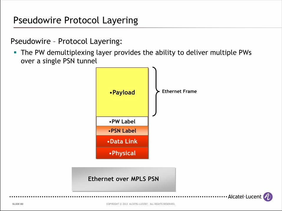
Pseudowire – Protocol Layering:
The PW demultiplexing layer provides the ability to deliver multiple PWs
over a single PSN tunnel
Pseudowire Protocol Layering
•Payload
•PW Label
•Physical
•Data Link
•PSN Label
Ethernet over MPLS PSN
Ethernet Frame
COPYRIGHT © 2013 ALCATEL-LUCENT. ALL RIGHTS RESERVED. SLIDE 81
4.3 Ethernet Virtual Private Wire Service (VPWS)
COPYRIGHT © 2013 ALCATEL-LUCENT. ALL RIGHTS RESERVED. SLIDE 82
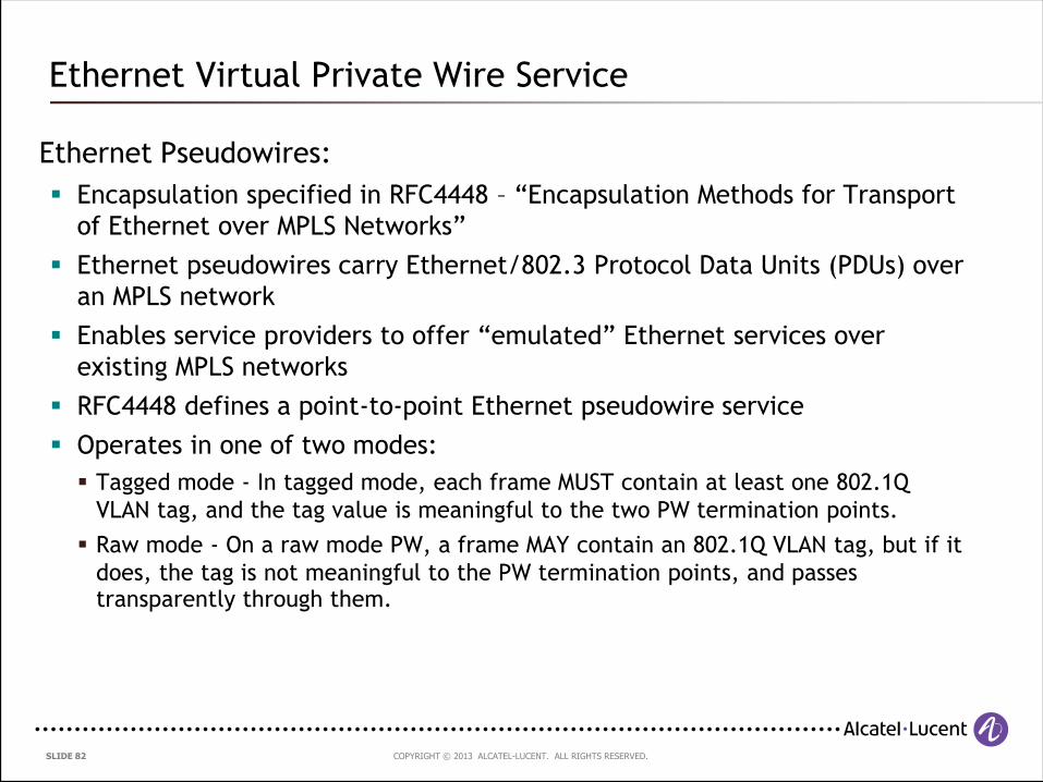
Ethernet Pseudowires:
Encapsulation specified in RFC4448 – “Encapsulation Methods for Transport
of Ethernet over MPLS Networks”
Ethernet pseudowires carry Ethernet/802.3 Protocol Data Units (PDUs) over
an MPLS network
Enables service providers to offer “emulated” Ethernet services over
existing MPLS networks
RFC4448 defines a point-to-point Ethernet pseudowire service
Operates in one of two modes:
Tagged mode - In tagged mode, each frame MUST contain at least one 802.1Q
VLAN tag, and the tag value is meaningful to the two PW termination points.
Raw mode - On a raw mode PW, a frame MAY contain an 802.1Q VLAN tag, but if it
does, the tag is not meaningful to the PW termination points, and passes transparently through them.
Ethernet Virtual Private Wire Service
COPYRIGHT © 2013 ALCATEL-LUCENT. ALL RIGHTS RESERVED. SLIDE 83
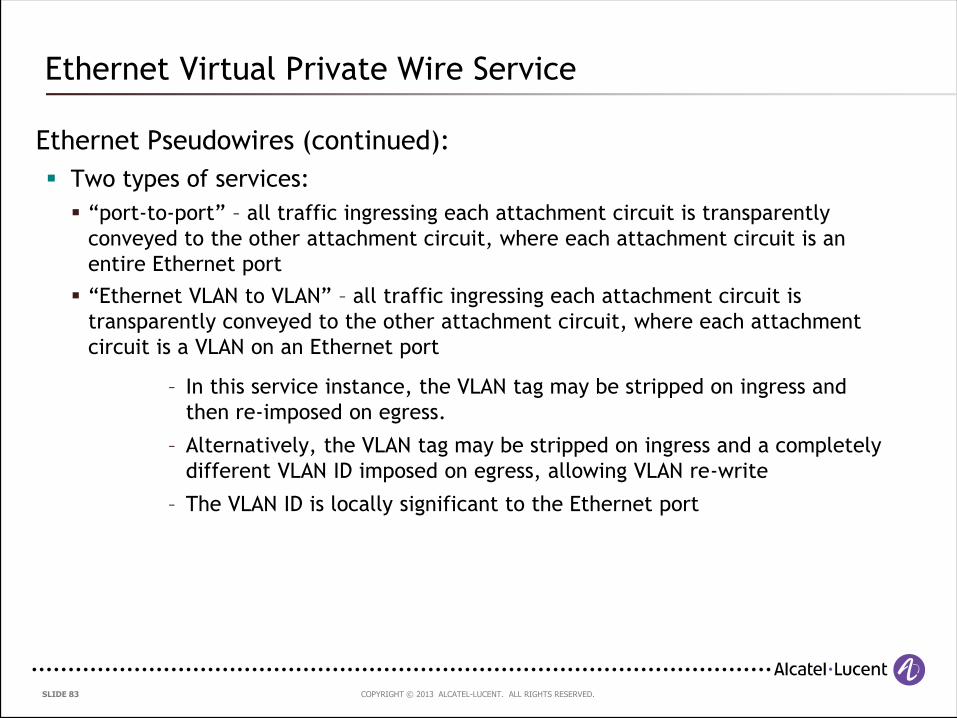
Ethernet Pseudowires (continued):
Two types of services:
“port-to-port” – all traffic ingressing each attachment circuit is transparently
conveyed to the other attachment circuit, where each attachment circuit is an
entire Ethernet port
“Ethernet VLAN to VLAN” – all traffic ingressing each attachment circuit is
transparently conveyed to the other attachment circuit, where each attachment
circuit is a VLAN on an Ethernet port
– In this service instance, the VLAN tag may be stripped on ingress and
then re-imposed on egress.
– Alternatively, the VLAN tag may be stripped on ingress and a completely
different VLAN ID imposed on egress, allowing VLAN re-write
– The VLAN ID is locally significant to the Ethernet port
Ethernet Virtual Private Wire Service
COPYRIGHT © 2013 ALCATEL-LUCENT. ALL RIGHTS RESERVED. SLIDE 84
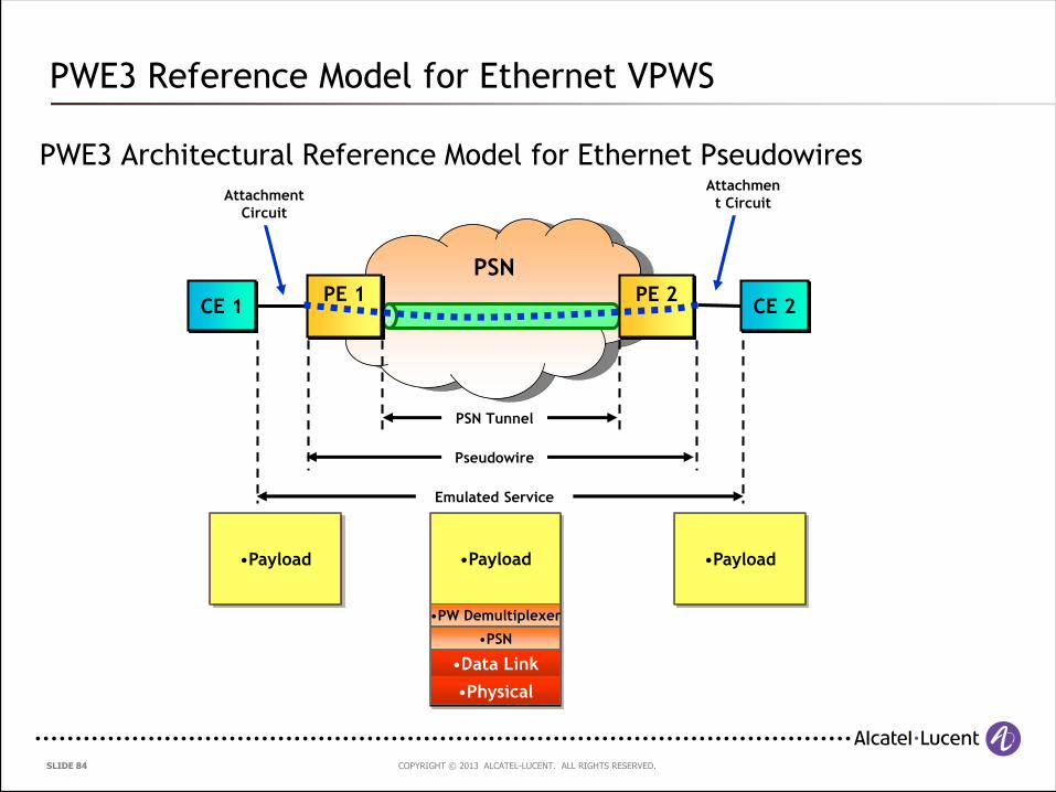
PWE3 Architectural Reference Model for Ethernet Pseudowires
PWE3 Reference Model for Ethernet VPWS
PSN
CE 1 CE 2
Emulated Service
Pseudowire
PSN Tunnel
Attachment
Circuit
Attachmen
t Circuit
PE 1 PE 2
•Payload •Payload
•PW Demultiplexer
•Physical
•Data Link
•PSN
•Payload
COPYRIGHT © 2013 ALCATEL-LUCENT. ALL RIGHTS RESERVED. SLIDE 85
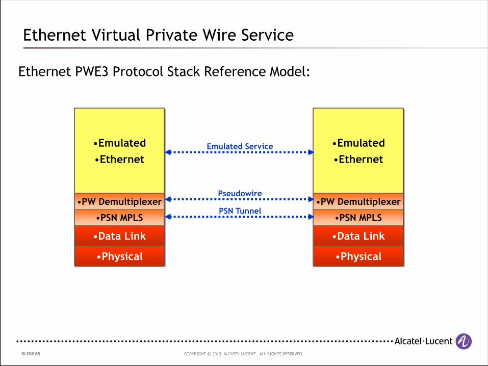
Ethernet PWE3 Protocol Stack Reference Model:
Ethernet Virtual Private Wire Service
•Emulated
•Ethernet
•PW Demultiplexer
•Physical
•Data Link
•PSN MPLS
Emulated Service •Emulated
•Ethernet
•PW Demultiplexer
•Physical
•Data Link
•PSN MPLS
Pseudowire
PSN Tunnel
COPYRIGHT © 2013 ALCATEL-LUCENT. ALL RIGHTS RESERVED. SLIDE 86
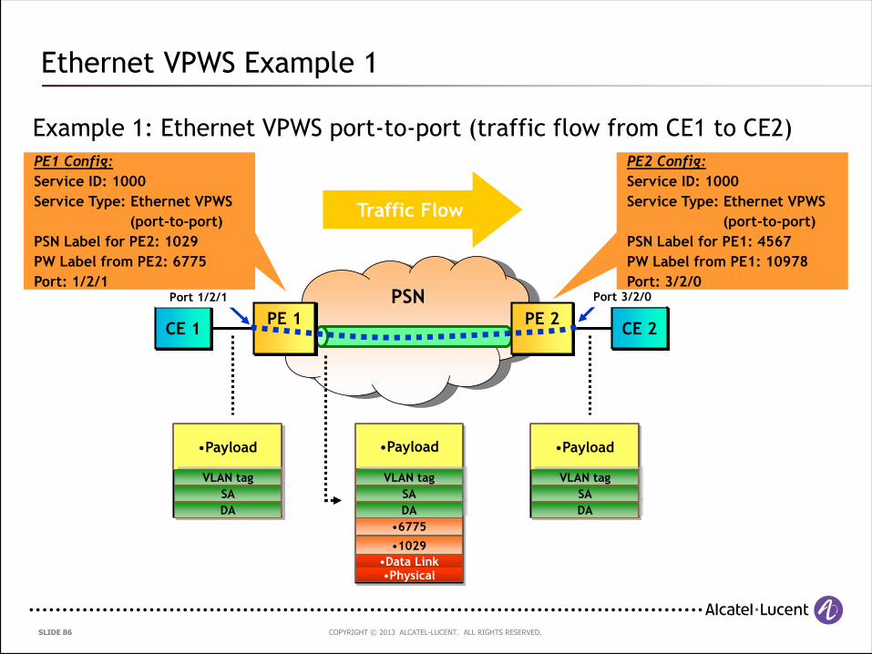
Example 1: Ethernet VPWS port-to-port (traffic flow from CE1 to CE2)
Ethernet VPWS Example 1
PSN
CE 1 CE 2
Port 1/2/1 Port 3/2/0
PE 1 PE 2
•Payload •Payload
•6775
•Physical•Data Link
•1029
PE1 Config:
Service ID: 1000
Service Type: Ethernet VPWS
(port-to-port)
PSN Label for PE2: 1029
PW Label from PE2: 6775
Port: 1/2/1
PE2 Config:
Service ID: 1000
Service Type: Ethernet VPWS
(port-to-port)
PSN Label for PE1: 4567
PW Label from PE1: 10978
Port: 3/2/0
Traffic Flow
DA
SA
VLAN tag
DA
SA
VLAN tag
•Payload
DA
SA
VLAN tag
COPYRIGHT © 2013 ALCATEL-LUCENT. ALL RIGHTS RESERVED. SLIDE 87
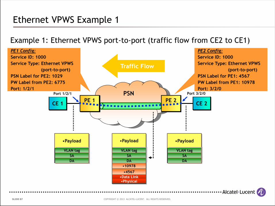
Example 1: Ethernet VPWS port-to-port (traffic flow from CE2 to CE1)
Ethernet VPWS Example 1
PSN
CE 1 CE 2
Port 1/2/1 Port 3/2/0
PE 1 PE 2
•Payload •Payload
•10978
•Physical•Data Link
•4567
PE1 Config:
Service ID: 1000
Service Type: Ethernet VPWS
(port-to-port)
PSN Label for PE2: 1029
PW Label from PE2: 6775
Port: 1/2/1
PE2 Config:
Service ID: 1000
Service Type: Ethernet VPWS
(port-to-port)
PSN Label for PE1: 4567
PW Label from PE1: 10978
Port: 3/2/0
Traffic Flow
DA
SA
VLAN tag
DA
SA
VLAN tag
•Payload
DA
SA
VLAN tag
COPYRIGHT © 2013 ALCATEL-LUCENT. ALL RIGHTS RESERVED. SLIDE 88
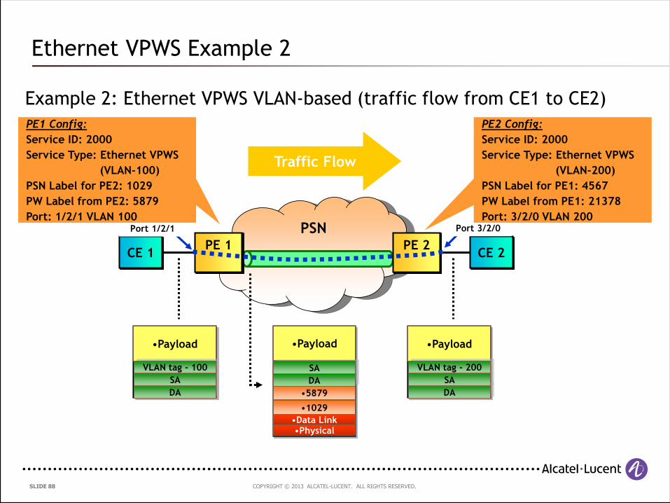
Example 2: Ethernet VPWS VLAN-based (traffic flow from CE1 to CE2)
Ethernet VPWS Example 2
PSN
CE 1 CE 2
Port 1/2/1 Port 3/2/0
PE 1 PE 2
•Payload •Payload
•5879
•Physical•Data Link
•1029
PE1 Config:
Service ID: 2000
Service Type: Ethernet VPWS
(VLAN-100)
PSN Label for PE2: 1029
PW Label from PE2: 5879
Port: 1/2/1 VLAN 100
PE2 Config:
Service ID: 2000
Service Type: Ethernet VPWS
(VLAN-200)
PSN Label for PE1: 4567
PW Label from PE1: 21378
Port: 3/2/0 VLAN 200
Traffic Flow
DA
SA
VLAN tag - 100
DA
SA
•Payload
DA
SA
VLAN tag - 200
COPYRIGHT © 2013 ALCATEL-LUCENT. ALL RIGHTS RESERVED. SLIDE 89
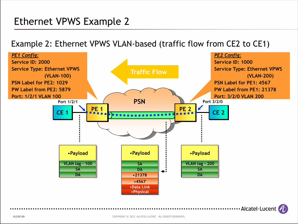
Example 2: Ethernet VPWS VLAN-based (traffic flow from CE2 to CE1)
Ethernet VPWS Example 2
PSN
CE 1 CE 2
Port 1/2/1 Port 3/2/0
PE 1 PE 2
•Payload •Payload
•21378
•Physical•Data Link
•4567
PE1 Config:
Service ID: 2000
Service Type: Ethernet VPWS
(VLAN-100)
PSN Label for PE2: 1029
PW Label from PE2: 5879
Port: 1/2/1 VLAN 100
PE2 Config:
Service ID: 1000
Service Type: Ethernet VPWS
(VLAN-200)
PSN Label for PE1: 4567
PW Label from PE1: 21378
Port: 3/2/0 VLAN 200
Traffic Flow
DA
SA
VLAN tag - 100
DA
SA
•Payload
DA
SA
VLAN tag - 200
COPYRIGHT © 2013 ALCATEL-LUCENT. ALL RIGHTS RESERVED. SLIDE 90
Ethernet Pseudowires – Setup and Maintenance:
Signalling specified in RFC4447 – “Pseudowire Setup and Maintenance Using
the Label Distribution Protocol (LDP)”
The MPLS Label Distribution Protocol, LDP [RFC5036], is used for setting up
and maintaining the pseudowires
PW label bindings are distributed using the LDP downstream unsolicited mode
PEs establish an LDP session using the LDP Extended Discovery mechanism a.k.a
Targeted LDP or tLDP
The PSN tunnels are established and maintained separately by using any of
the following:
The Label Distribution Protocol (LDP)
The Resource Reservation Protocol with Traffic Engineering (RSVP-TE)
Static labels
Ethernet Virtual Private Wire Service
COPYRIGHT © 2013 ALCATEL-LUCENT. ALL RIGHTS RESERVED. SLIDE 91
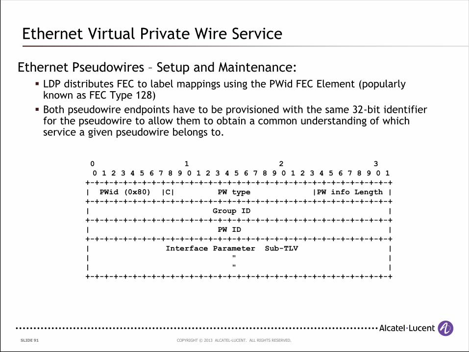
Ethernet Pseudowires – Setup and Maintenance:
LDP distributes FEC to label mappings using the PWid FEC Element (popularly known as FEC Type 128)
Both pseudowire endpoints have to be provisioned with the same 32-bit identifier for the pseudowire to allow them to obtain a common understanding of which service a given pseudowire belongs to.
Ethernet Virtual Private Wire Service
0 1 2 3
0 1 2 3 4 5 6 7 8 9 0 1 2 3 4 5 6 7 8 9 0 1 2 3 4 5 6 7 8 9 0 1
+-+-+-+-+-+-+-+-+-+-+-+-+-+-+-+-+-+-+-+-+-+-+-+-+-+-+-+-+-+-+-+-+
| PWid (0x80) |C| PW type |PW info Length |
+-+-+-+-+-+-+-+-+-+-+-+-+-+-+-+-+-+-+-+-+-+-+-+-+-+-+-+-+-+-+-+-+
| Group ID |
+-+-+-+-+-+-+-+-+-+-+-+-+-+-+-+-+-+-+-+-+-+-+-+-+-+-+-+-+-+-+-+-+
| PW ID |
+-+-+-+-+-+-+-+-+-+-+-+-+-+-+-+-+-+-+-+-+-+-+-+-+-+-+-+-+-+-+-+-+
| Interface Parameter Sub-TLV |
| " |
| " |
+-+-+-+-+-+-+-+-+-+-+-+-+-+-+-+-+-+-+-+-+-+-+-+-+-+-+-+-+-+-+-+-+
COPYRIGHT © 2013 ALCATEL-LUCENT. ALL RIGHTS RESERVED. SLIDE 92
Ethernet Pseudowires – Setup and Maintenance:
A new TLV, the Generalized PWid FEC Element (popularly known as FEC Type 129)
has also been developed but is not widely deployed as yet
The Generalized PWid FEC element requires that the PW endpoints be uniquely
identified; the PW itself is identified as a pair of endpoints. In addition, the
endpoint identifiers are structured to support applications where the identity of
the remote endpoints needs to be auto-discovered rather than statically
configured.
Ethernet Virtual Private Wire Service
COPYRIGHT © 2013 ALCATEL-LUCENT. ALL RIGHTS RESERVED. SLIDE 93
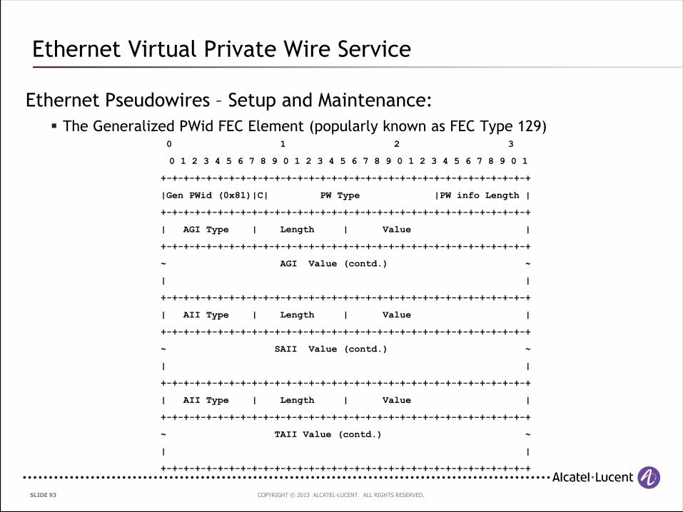
Ethernet Pseudowires – Setup and Maintenance:
The Generalized PWid FEC Element (popularly known as FEC Type 129)
Ethernet Virtual Private Wire Service
0 1 2 3
0 1 2 3 4 5 6 7 8 9 0 1 2 3 4 5 6 7 8 9 0 1 2 3 4 5 6 7 8 9 0 1
+-+-+-+-+-+-+-+-+-+-+-+-+-+-+-+-+-+-+-+-+-+-+-+-+-+-+-+-+-+-+-+-+
|Gen PWid (0x81)|C| PW Type |PW info Length |
+-+-+-+-+-+-+-+-+-+-+-+-+-+-+-+-+-+-+-+-+-+-+-+-+-+-+-+-+-+-+-+-+
| AGI Type | Length | Value |
+-+-+-+-+-+-+-+-+-+-+-+-+-+-+-+-+-+-+-+-+-+-+-+-+-+-+-+-+-+-+-+-+
~ AGI Value (contd.) ~
| |
+-+-+-+-+-+-+-+-+-+-+-+-+-+-+-+-+-+-+-+-+-+-+-+-+-+-+-+-+-+-+-+-+
| AII Type | Length | Value |
+-+-+-+-+-+-+-+-+-+-+-+-+-+-+-+-+-+-+-+-+-+-+-+-+-+-+-+-+-+-+-+-+
~ SAII Value (contd.) ~
| |
+-+-+-+-+-+-+-+-+-+-+-+-+-+-+-+-+-+-+-+-+-+-+-+-+-+-+-+-+-+-+-+-+
| AII Type | Length | Value |
+-+-+-+-+-+-+-+-+-+-+-+-+-+-+-+-+-+-+-+-+-+-+-+-+-+-+-+-+-+-+-+-+
~ TAII Value (contd.) ~
| |
+-+-+-+-+-+-+-+-+-+-+-+-+-+-+-+-+-+-+-+-+-+-+-+-+-+-+-+-+-+-+-+-+
COPYRIGHT © 2013 ALCATEL-LUCENT. ALL RIGHTS RESERVED. SLIDE 94
What protocol is used to exchange pseudowire labels between provider edge routers ?
Audience Question 5
COPYRIGHT © 2013 ALCATEL-LUCENT. ALL RIGHTS RESERVED. SLIDE 95
4.4 Ethernet Virtual Private LAN Service (VPLS)
COPYRIGHT © 2013 ALCATEL-LUCENT. ALL RIGHTS RESERVED. SLIDE 96
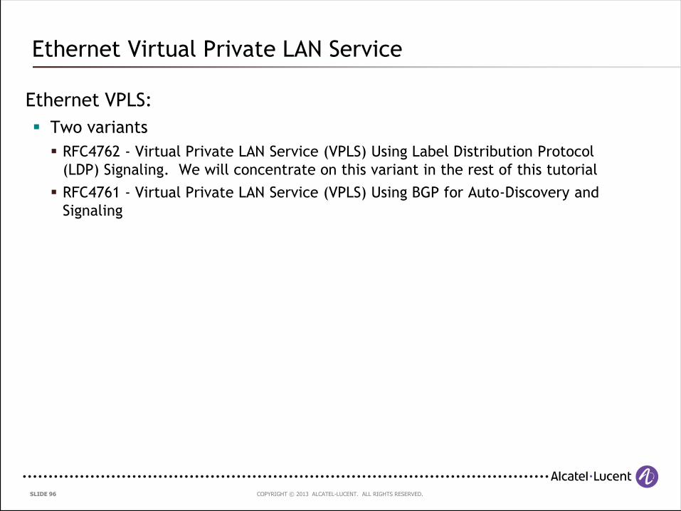
Ethernet VPLS:
Two variants
RFC4762 - Virtual Private LAN Service (VPLS) Using Label Distribution Protocol
(LDP) Signaling. We will concentrate on this variant in the rest of this tutorial
RFC4761 - Virtual Private LAN Service (VPLS) Using BGP for Auto-Discovery and
Signaling
Ethernet Virtual Private LAN Service
COPYRIGHT © 2013 ALCATEL-LUCENT. ALL RIGHTS RESERVED. SLIDE 97
Definition:
A VPLS creates an emulated private LAN segment for a given set of users.
It creates a Layer 2 broadcast domain that is fully capable of learning and
forwarding on Ethernet MAC addresses and that is closed to a given set of
users. Multiple VPLS services can be supported from a single Provider Edge
(PE) node.
The primary motivation behind VPLS is to provide connectivity between
geographically dispersed customer sites across MANs and WANs, as if they
were connected using a LAN.
The main intended application for the end-user can be divided into the
following two categories:
Connectivity between customer routers: LAN routing application
Connectivity between customer Ethernet switches: LAN switching application
Ethernet Virtual Private LAN Service
COPYRIGHT © 2013 ALCATEL-LUCENT. ALL RIGHTS RESERVED. SLIDE 98
Benefits for the customer:
Simplicity
Behaves like an “ethernet switch in the sky”
No routing interaction with the provider
Clear demarcation between subscriber and provider
Layer 3 agnostic
Scalable
Provider configures site connectivity only
Hierarchy reduces number of sites touched
Multi-site connectivity
On the fly connectivity via Ethernet bridging
VPLS Benefits
COPYRIGHT © 2013 ALCATEL-LUCENT. ALL RIGHTS RESERVED. SLIDE 99
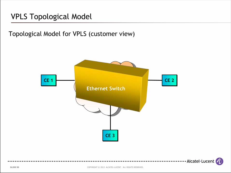
Topological Model for VPLS (customer view)
VPLS Topological Model
PSN
CE 1 CE 2
CE 3
Ethernet Switch
COPYRIGHT © 2013 ALCATEL-LUCENT. ALL RIGHTS RESERVED. SLIDE 100
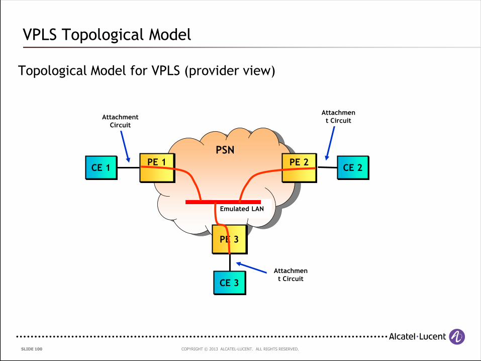
Topological Model for VPLS (provider view)
VPLS Topological Model
PSN
CE 1 CE 2
Emulated LAN
Attachment
Circuit
Attachmen
t Circuit
PE 1 PE 2
CE 3
PE 3
Attachmen
t Circuit
COPYRIGHT © 2013 ALCATEL-LUCENT. ALL RIGHTS RESERVED. SLIDE 101
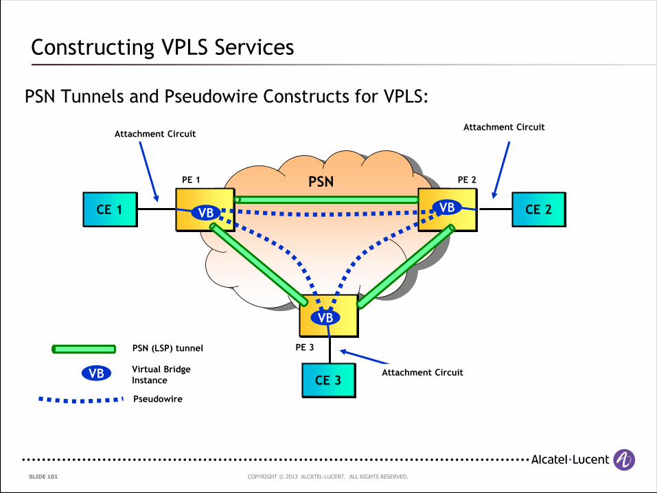
PSN Tunnels and Pseudowire Constructs for VPLS:
Constructing VPLS Services
PSN
CE 1 CE 2
Attachment Circuit Attachment Circuit
CE 3Attachment Circuit
PSN (LSP) tunnel
VB
VB
PE 1 PE 2
PE 3
VBVB
Virtual Bridge
Instance
Pseudowire
COPYRIGHT © 2013 ALCATEL-LUCENT. ALL RIGHTS RESERVED. SLIDE 102
Provider Edge Functions:
PE interfaces participating in a VPLS instance are able to flood, forward,
and filter Ethernet frames, like a standard Ethernet bridged port
Many forms of Attachment Circuits are acceptable, as long as they carry
Ethernet frames:
Physical Ethernet ports
Logical (tagged) Ethernet ports
ATM PVCs carrying Ethernet frames
Ethernet Pseudowire
Frames sent to broadcast addresses and to unknown destination MAC
addresses are flooded to all ports:
Attachment Circuits
Pseudowires to all other PE nodes participating in the VPLS service
PEs have the capability to associate MAC addresses with Pseudowires
VPLS PE Functions
COPYRIGHT © 2013 ALCATEL-LUCENT. ALL RIGHTS RESERVED. SLIDE 103
Provider Edge Functions (continued):
Address learning:
Unlike BGP VPNs [RFC4364], reachability information is not advertised and
distributed via a control plane.
Reachability is obtained by standard learning bridge functions in the data plane.
When a packet arrives on a PW, if the source MAC address is unknown, it is
associated with the PW, so that outbound packets to that MAC address can be
delivered over the associated PW.
When a packet arrives on an AC, if the source MAC address is unknown, it is
associated with the AC, so that outbound packets to that MAC address can be
delivered over the associated AC.
VPLS PE Functions
COPYRIGHT © 2013 ALCATEL-LUCENT. ALL RIGHTS RESERVED. SLIDE 104
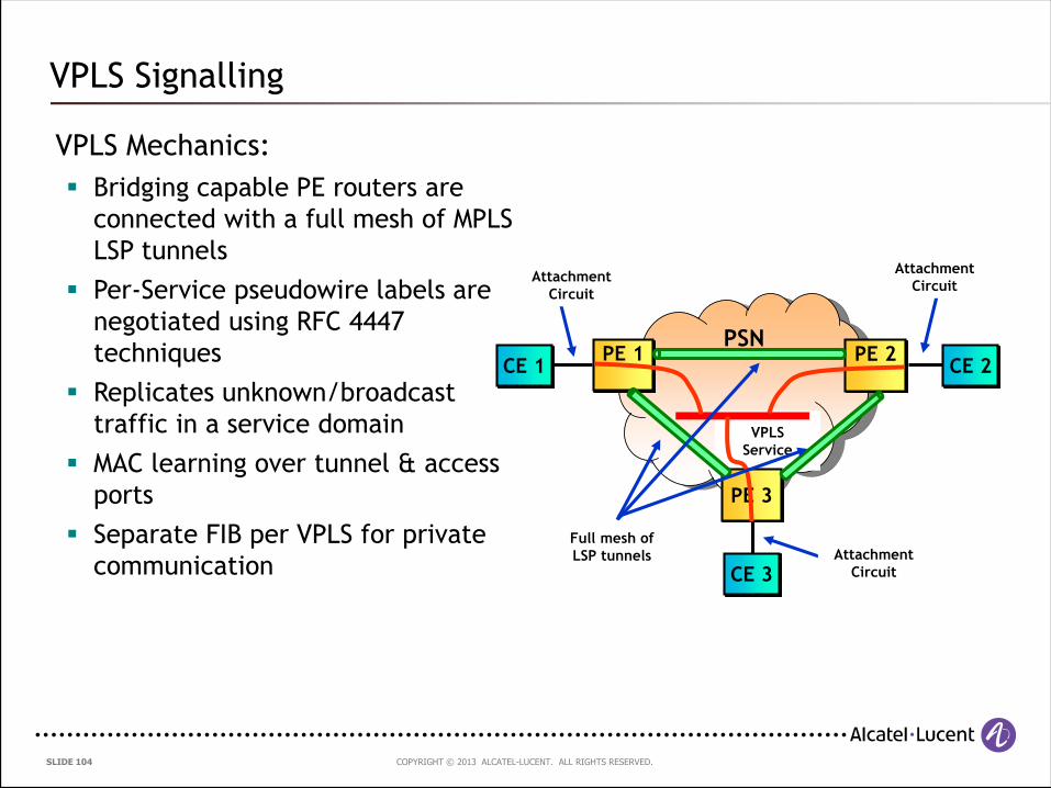
VPLS Signalling
VPLS Mechanics:
Bridging capable PE routers are
connected with a full mesh of MPLS
LSP tunnels
Per-Service pseudowire labels are
negotiated using RFC 4447
techniques
Replicates unknown/broadcast
traffic in a service domain
MAC learning over tunnel & access
ports
Separate FIB per VPLS for private
communication
PSNCE 1 CE 2
VPLS
Service
Attachment
Circuit
Attachment
Circuit
PE 1 PE 2
CE 3
PE 3
Attachment
Circuit
Full mesh of
LSP tunnels
COPYRIGHT © 2013 ALCATEL-LUCENT. ALL RIGHTS RESERVED. SLIDE 105
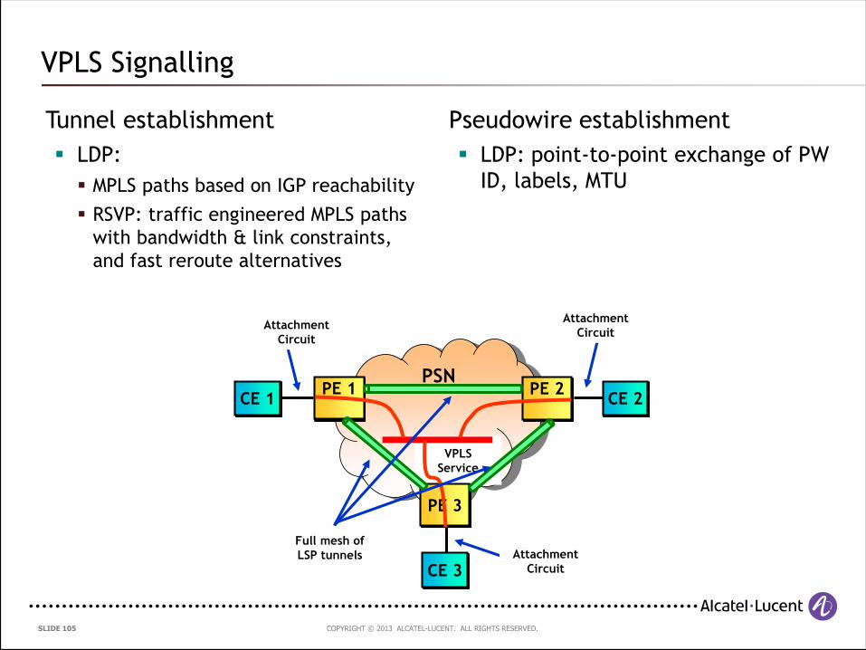
VPLS Signalling
Tunnel establishment
LDP:
MPLS paths based on IGP reachability
RSVP: traffic engineered MPLS paths
with bandwidth & link constraints,
and fast reroute alternatives
Pseudowire establishment
LDP: point-to-point exchange of PW
ID, labels, MTU
PSNCE 1 CE 2
VPLS
Service
Attachment
Circuit
Attachment
Circuit
PE 1 PE 2
CE 3
PE 3
Attachment
Circuit
Full mesh of
LSP tunnels
COPYRIGHT © 2013 ALCATEL-LUCENT. ALL RIGHTS RESERVED. SLIDE 106
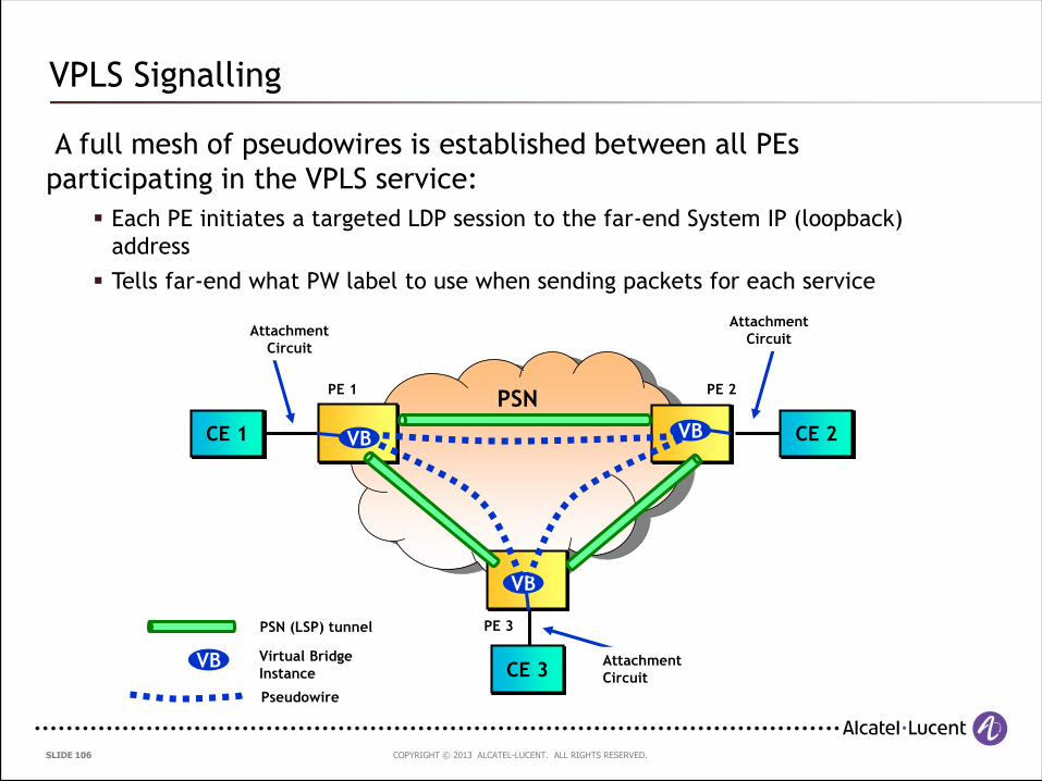
VPLS Signalling
A full mesh of pseudowires is established between all PEs
participating in the VPLS service:
Each PE initiates a targeted LDP session to the far-end System IP (loopback)
address
Tells far-end what PW label to use when sending packets for each service
PSN
CE 1 CE 2
Attachment
Circuit
Attachment
Circuit
CE 3Attachment
Circuit
PSN (LSP) tunnel
VB
VB
PE 1 PE 2
PE 3
VBVB
Virtual Bridge
Instance
Pseudowire
COPYRIGHT © 2013 ALCATEL-LUCENT. ALL RIGHTS RESERVED. SLIDE 107
VPLS Signalling
Why a full mesh of pseudowires?
If the topology of the VPLS is not restricted to a full mesh, then it may
be that for two PEs not directly connected via PWs, they would have to
use an intermediary PE to relay packets
A loop-breaking protocol, such as the Spanning Tree Protocol, would be
required
With a full-mesh of PWs, every PE is now directly connected to every
other PE in the VPLS via a PW; there is no longer any need to relay
packets
The loop-breaking rule now becomes the "split horizon" rule, whereby a
PE MUST NOT forward traffic received from one PW to another in the
same VPLS mesh
Does this remind you of a similar mechanism used in IP networks ? The ibgp
full-mesh !
COPYRIGHT © 2013 ALCATEL-LUCENT. ALL RIGHTS RESERVED. SLIDE 108
Ethernet Pseudowires – Setup and Maintenance:
Signalling specified in RFC4447 – “Pseudowire Setup and Maintenance Using
the Label Distribution Protocol (LDP)”
The MPLS Label Distribution Protocol, LDP [RFC5036], is used for setting up
and maintaining the pseudowires
PW label bindings are distributed using the LDP downstream unsolicited mode
PEs establish an LDP session using the LDP Extended Discovery mechanism a.k.a
Targeted LDP or tLDP
The PSN tunnels are established and maintained separately by using any of
the following:
The Label Distribution Protocol (LDP)
The Resource Reservation Protocol with Traffic Engineering (RSVP-TE)
Static labels
VPLS Pseudowire Signalling
COPYRIGHT © 2013 ALCATEL-LUCENT. ALL RIGHTS RESERVED. SLIDE 109
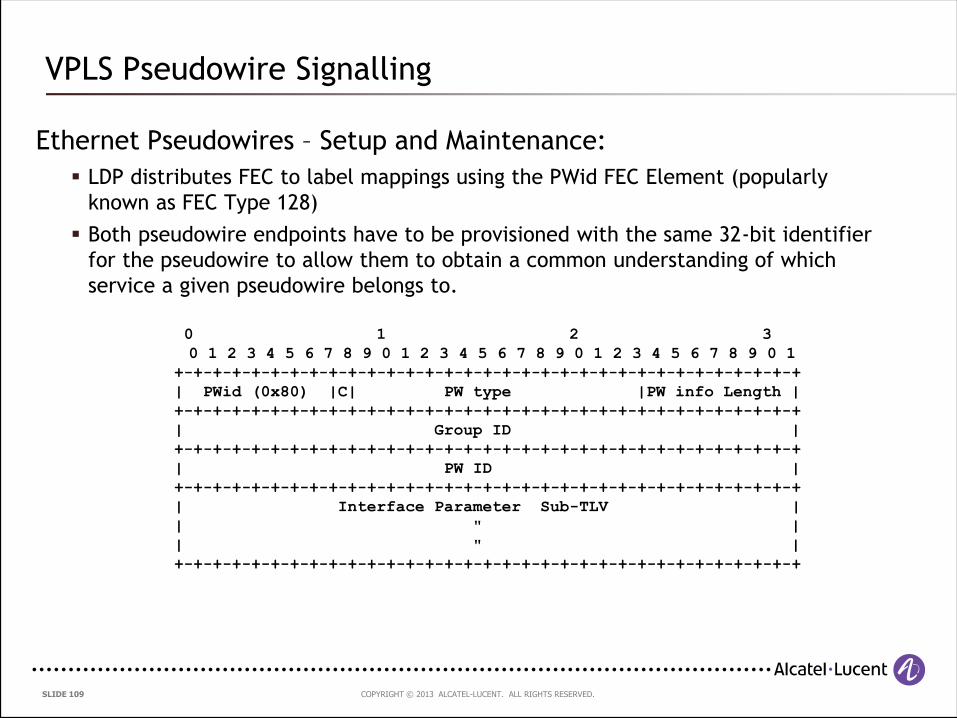
Ethernet Pseudowires – Setup and Maintenance:
LDP distributes FEC to label mappings using the PWid FEC Element (popularly
known as FEC Type 128)
Both pseudowire endpoints have to be provisioned with the same 32-bit identifier
for the pseudowire to allow them to obtain a common understanding of which
service a given pseudowire belongs to.
VPLS Pseudowire Signalling
0 1 2 3
0 1 2 3 4 5 6 7 8 9 0 1 2 3 4 5 6 7 8 9 0 1 2 3 4 5 6 7 8 9 0 1
+-+-+-+-+-+-+-+-+-+-+-+-+-+-+-+-+-+-+-+-+-+-+-+-+-+-+-+-+-+-+-+-+
| PWid (0x80) |C| PW type |PW info Length |
+-+-+-+-+-+-+-+-+-+-+-+-+-+-+-+-+-+-+-+-+-+-+-+-+-+-+-+-+-+-+-+-+
| Group ID |
+-+-+-+-+-+-+-+-+-+-+-+-+-+-+-+-+-+-+-+-+-+-+-+-+-+-+-+-+-+-+-+-+
| PW ID |
+-+-+-+-+-+-+-+-+-+-+-+-+-+-+-+-+-+-+-+-+-+-+-+-+-+-+-+-+-+-+-+-+
| Interface Parameter Sub-TLV |
| " |
| " |
+-+-+-+-+-+-+-+-+-+-+-+-+-+-+-+-+-+-+-+-+-+-+-+-+-+-+-+-+-+-+-+-+
COPYRIGHT © 2013 ALCATEL-LUCENT. ALL RIGHTS RESERVED. SLIDE 110
Ethernet Pseudowires – Setup and Maintenance:
A new TLV, the Generalized PWid FEC Element (popularly known as FEC Type 129)
has also been developed but is not widely deployed as yet
The Generalized PWid FEC element requires that the PW endpoints be uniquely
identified; the PW itself is identified as a pair of endpoints. In addition, the
endpoint identifiers are structured to support applications where the identity of
the remote endpoints needs to be auto-discovered rather than statically
configured.
VPLS Pseudowire Signalling
COPYRIGHT © 2013 ALCATEL-LUCENT. ALL RIGHTS RESERVED. SLIDE 111
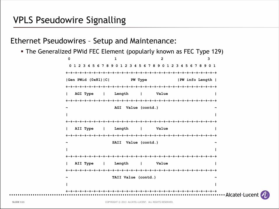
Ethernet Pseudowires – Setup and Maintenance:
The Generalized PWid FEC Element (popularly known as FEC Type 129)
VPLS Pseudowire Signalling
0 1 2 3
0 1 2 3 4 5 6 7 8 9 0 1 2 3 4 5 6 7 8 9 0 1 2 3 4 5 6 7 8 9 0 1
+-+-+-+-+-+-+-+-+-+-+-+-+-+-+-+-+-+-+-+-+-+-+-+-+-+-+-+-+-+-+-+-+
|Gen PWid (0x81)|C| PW Type |PW info Length |
+-+-+-+-+-+-+-+-+-+-+-+-+-+-+-+-+-+-+-+-+-+-+-+-+-+-+-+-+-+-+-+-+
| AGI Type | Length | Value |
+-+-+-+-+-+-+-+-+-+-+-+-+-+-+-+-+-+-+-+-+-+-+-+-+-+-+-+-+-+-+-+-+
~ AGI Value (contd.) ~
| |
+-+-+-+-+-+-+-+-+-+-+-+-+-+-+-+-+-+-+-+-+-+-+-+-+-+-+-+-+-+-+-+-+
| AII Type | Length | Value |
+-+-+-+-+-+-+-+-+-+-+-+-+-+-+-+-+-+-+-+-+-+-+-+-+-+-+-+-+-+-+-+-+
~ SAII Value (contd.) ~
| |
+-+-+-+-+-+-+-+-+-+-+-+-+-+-+-+-+-+-+-+-+-+-+-+-+-+-+-+-+-+-+-+-+
| AII Type | Length | Value |
+-+-+-+-+-+-+-+-+-+-+-+-+-+-+-+-+-+-+-+-+-+-+-+-+-+-+-+-+-+-+-+-+
~ TAII Value (contd.) ~
| |
+-+-+-+-+-+-+-+-+-+-+-+-+-+-+-+-+-+-+-+-+-+-+-+-+-+-+-+-+-+-+-+-+
COPYRIGHT © 2013 ALCATEL-LUCENT. ALL RIGHTS RESERVED. SLIDE 112
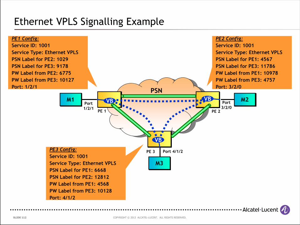
Ethernet VPLS Signalling Example
PE1 Config:
Service ID: 1001
Service Type: Ethernet VPLS
PSN Label for PE2: 1029
PSN Label for PE3: 9178
PW Label from PE2: 6775
PW Label from PE3: 10127
Port: 1/2/1
PE2 Config:
Service ID: 1001
Service Type: Ethernet VPLS
PSN Label for PE1: 4567
PSN Label for PE3: 11786
PW Label from PE1: 10978
PW Label from PE3: 4757
Port: 3/2/0
Port
1/2/1
Port
3/2/0
PSN
M1 M2
M3
VB
PE 1 PE 2
PE 3
VBVB
PE3 Config:
Service ID: 1001
Service Type: Ethernet VPLS
PSN Label for PE1: 6668
PSN Label for PE2: 12812
PW Label from PE1: 4568
PW Label from PE3: 10128
Port: 4/1/2
Port 4/1/2
COPYRIGHT © 2013 ALCATEL-LUCENT. ALL RIGHTS RESERVED. SLIDE 113
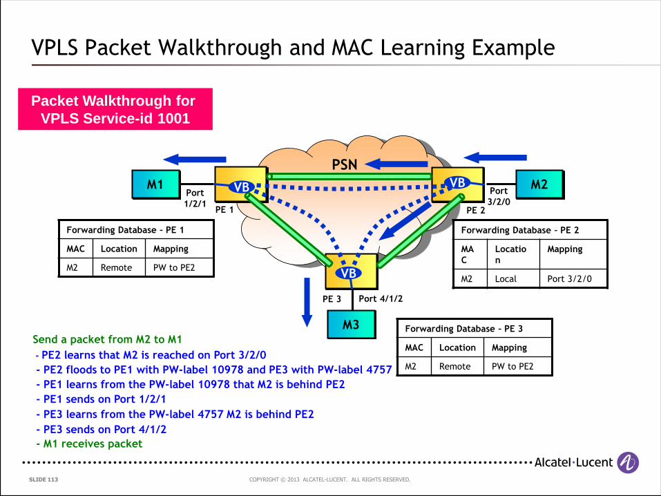
VPLS Packet Walkthrough and MAC Learning Example
Port
1/2/1
Port
3/2/0
PSN
M1 M2
M3
VB
PE 1 PE 2
PE 3
VBVB
Port 4/1/2
Packet Walkthrough for
VPLS Service-id 1001
Send a packet from M2 to M1
- PE2 learns that M2 is reached on Port 3/2/0
- PE2 floods to PE1 with PW-label 10978 and PE3 with PW-label 4757
- PE1 learns from the PW-label 10978 that M2 is behind PE2
- PE1 sends on Port 1/2/1
- PE3 sends on Port 4/1/2
- PE3 learns from the PW-label 4757 M2 is behind PE2
- M1 receives packet
Forwarding Database – PE 2
MA
C
Locatio
n
Mapping
M2 Local Port 3/2/0
Forwarding Database – PE 3
MAC Location Mapping
M2 Remote PW to PE2
Forwarding Database – PE 1
MAC Location Mapping
M2 Remote PW to PE2
COPYRIGHT © 2013 ALCATEL-LUCENT. ALL RIGHTS RESERVED. SLIDE 114
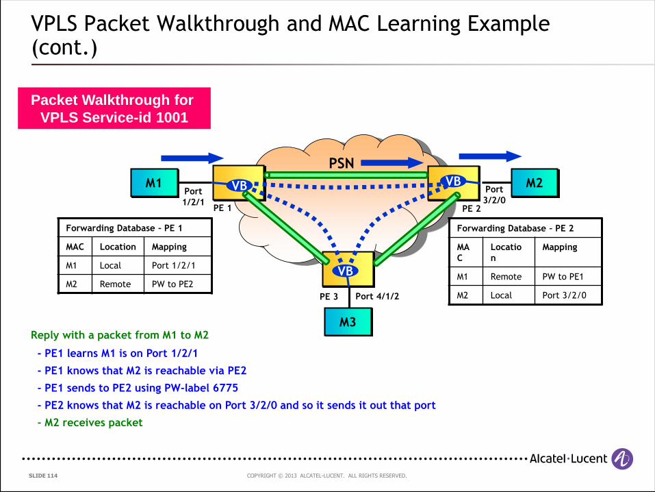
VPLS Packet Walkthrough and MAC Learning Example (cont.)
Port
1/2/1
Port
3/2/0
PSN
M1 M2
M3
VB
PE 1 PE 2
PE 3
VBVB
Port 4/1/2
Packet Walkthrough for
VPLS Service-id 1001
Forwarding Database – PE 2
MA
C
Locatio
n
Mapping
M1 Remote PW to PE1
M2 Local Port 3/2/0
Forwarding Database – PE 1
MAC Location Mapping
M1 Local Port 1/2/1
M2 Remote PW to PE2
Reply with a packet from M1 to M2
- PE1 learns M1 is on Port 1/2/1
- PE1 knows that M2 is reachable via PE2
- PE1 sends to PE2 using PW-label 6775
- PE2 knows that M2 is reachable on Port 3/2/0 and so it sends it out that port
- M2 receives packet
COPYRIGHT © 2013 ALCATEL-LUCENT. ALL RIGHTS RESERVED. SLIDE 115
If a full-mesh VPLS is set up between 5 provider edge routers, how many pseudowires need to be
configured ?
Audience Question 6
COPYRIGHT © 2013 ALCATEL-LUCENT. ALL RIGHTS RESERVED. SLIDE 116
4.5 Scaling VPLS
COPYRIGHT © 2013 ALCATEL-LUCENT. ALL RIGHTS RESERVED. SLIDE 117
PE-1
PE-2
VPLS
M-1
M-3
VB
VB
VB
PE-3
VB
M-5
M-6
VB
MTU-1
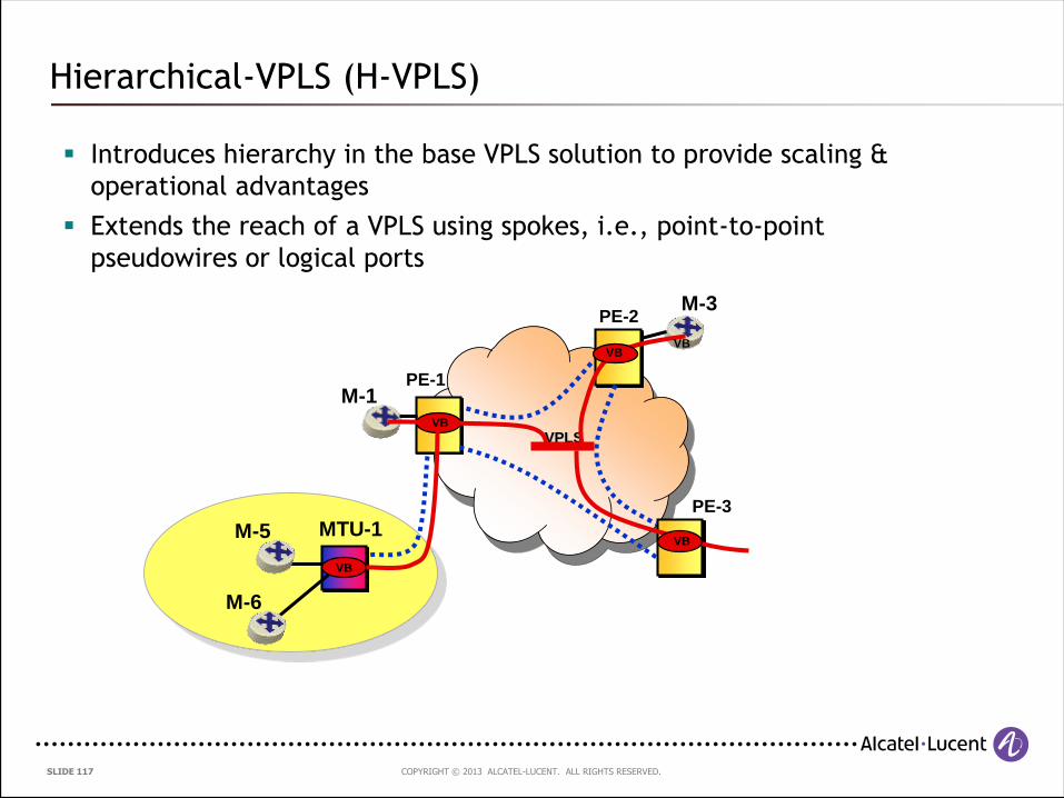
Hierarchical-VPLS (H-VPLS)
Introduces hierarchy in the base VPLS solution to provide scaling &
operational advantages
Extends the reach of a VPLS using spokes, i.e., point-to-point
pseudowires or logical ports
COPYRIGHT © 2013 ALCATEL-LUCENT. ALL RIGHTS RESERVED. SLIDE 118
Hierarchical VPLS
How is a spoke useful?
Scales signalling
Full-mesh between MTUs is reduced to full-mesh between PEs and
single PW between MTU and PE
Scales replication
Replication at MTU is not required
Replication is reduced to what is necessary between PEs
Simplifies edge devices
Keeps cost down because PEs can be replaced with MTUs
Enables scalable inter-domain VPLS
Single spoke to interconnect domains
COPYRIGHT © 2013 ALCATEL-LUCENT. ALL RIGHTS RESERVED. SLIDE 119
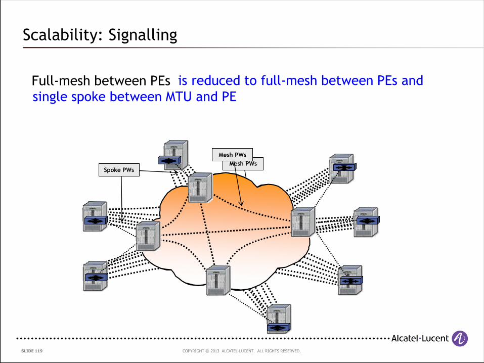
Scalability: Signalling
is reduced to full-mesh between PEs and
single spoke between MTU and PE
Mesh PWsSpoke PWs
Mesh PWs
Full-mesh between PEs
COPYRIGHT © 2013 ALCATEL-LUCENT. ALL RIGHTS RESERVED. SLIDE 120
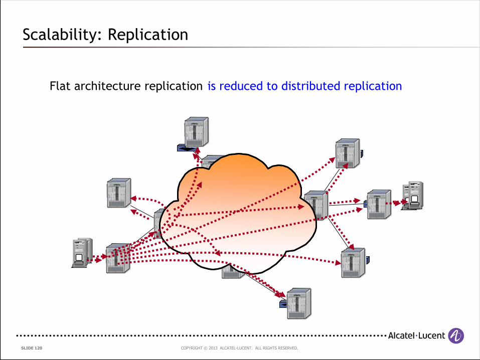
Scalability: Replication
Flat architecture replication is reduced to distributed replication
COPYRIGHT © 2013 ALCATEL-LUCENT. ALL RIGHTS RESERVED. SLIDE 121
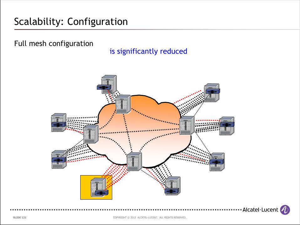
Scalability: Configuration
Full mesh configurationis significantly reduced
COPYRIGHT © 2013 ALCATEL-LUCENT. ALL RIGHTS RESERVED. SLIDE 122
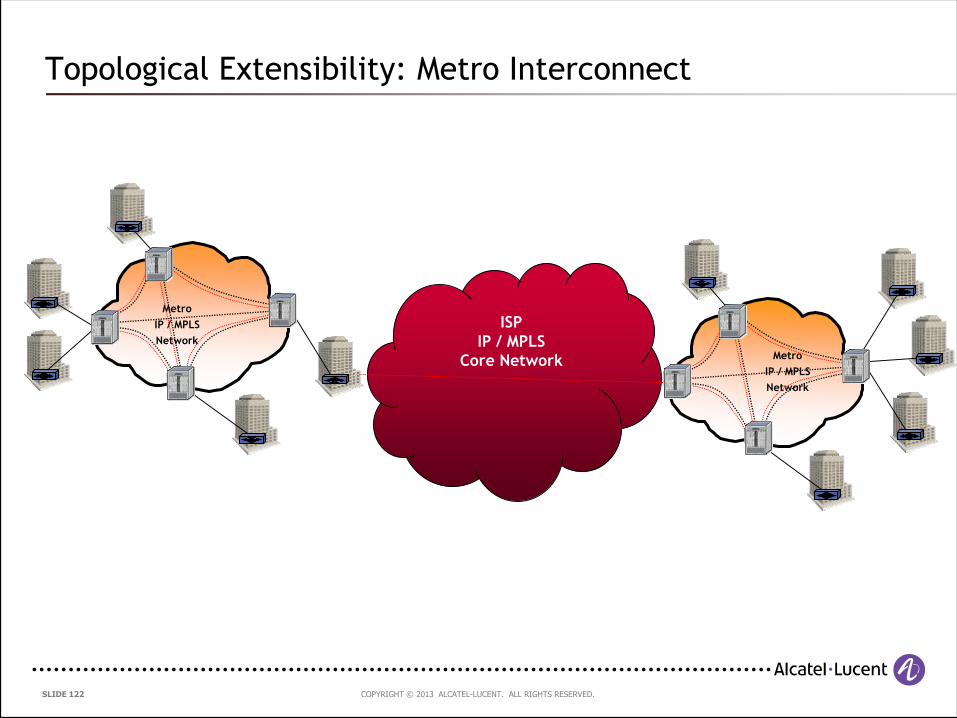
Topological Extensibility: Metro Interconnect
ISP
IP / MPLS
Core Network
Metro
IP / MPLS
Network
Metro
IP / MPLS
Network
COPYRIGHT © 2013 ALCATEL-LUCENT. ALL RIGHTS RESERVED. SLIDE 123
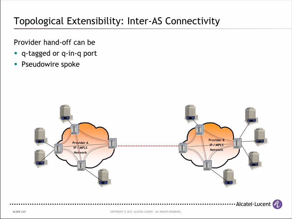
Topological Extensibility: Inter-AS Connectivity
Provider hand-off can be
q-tagged or q-in-q port
Pseudowire spoke
Provider A
IP / MPLS
Network
Provider B
IP / MPLS
Network
COPYRIGHT © 2013 ALCATEL-LUCENT. ALL RIGHTS RESERVED. SLIDE 124
4.6 VPLS Topologies
COPYRIGHT © 2013 ALCATEL-LUCENT. ALL RIGHTS RESERVED. SLIDE 125
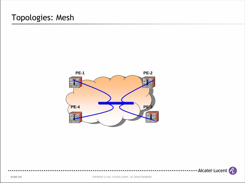
Topologies: Mesh
PE-4
PE-1
PE-3
PE-2
COPYRIGHT © 2013 ALCATEL-LUCENT. ALL RIGHTS RESERVED. SLIDE 126
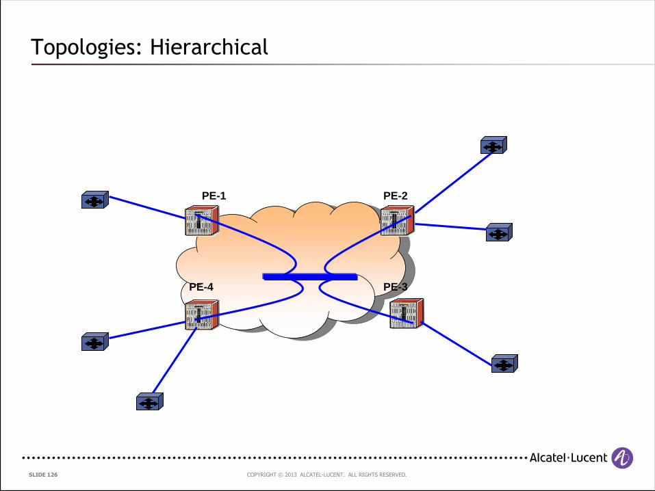
Topologies: Hierarchical
PE-4
PE-1
PE-3
PE-2
COPYRIGHT © 2013 ALCATEL-LUCENT. ALL RIGHTS RESERVED. SLIDE 127
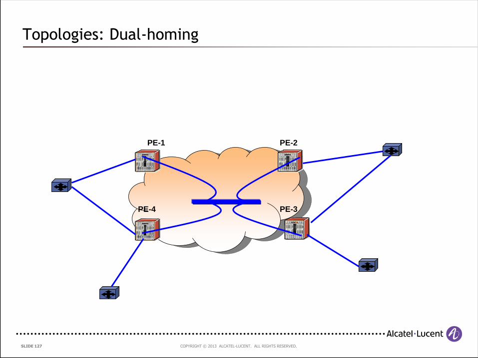
Topologies: Dual-homing
PE-4
PE-1
PE-3
PE-2
COPYRIGHT © 2013 ALCATEL-LUCENT. ALL RIGHTS RESERVED. SLIDE 128
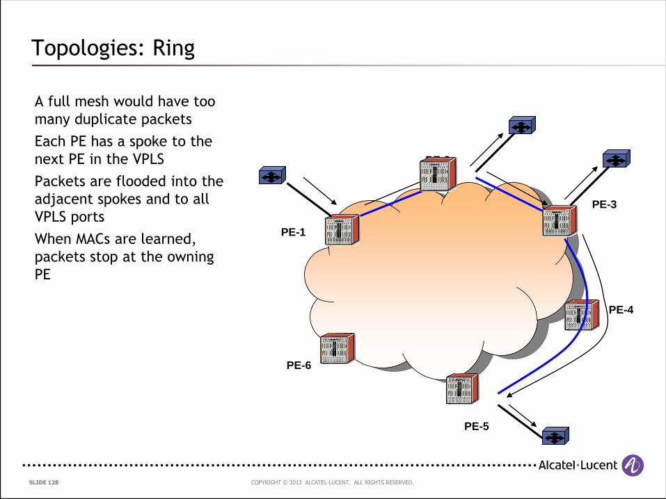
Topologies: Ring
A full mesh would have too
many duplicate packets
Each PE has a spoke to the
next PE in the VPLS
Packets are flooded into the
adjacent spokes and to all
VPLS ports
When MACs are learned,
packets stop at the owning
PE
PE-6
PE-1
PE-4
PE-3
PE-2
PE-5
COPYRIGHT © 2013 ALCATEL-LUCENT. ALL RIGHTS RESERVED. SLIDE 129
4.7 Resiliency Mechanisms
COPYRIGHT © 2013 ALCATEL-LUCENT. ALL RIGHTS RESERVED. SLIDE 130
Agenda
4.7. Resiliency Mechanisms
4.7.1 Multi-Chassis LAG (MC-LAG)
4.7.2 Redundancy with VPLS
4.7.3 Pseudo-wire Redundancy with MC-LAG
4.7.4 Multi-Segment Pseudo-wires
COPYRIGHT © 2013 ALCATEL-LUCENT. ALL RIGHTS RESERVED. SLIDE 131
4.7.1 Multi-Chassis LAG (MC-LAG)
COPYRIGHT © 2013 ALCATEL-LUCENT. ALL RIGHTS RESERVED. SLIDE 132
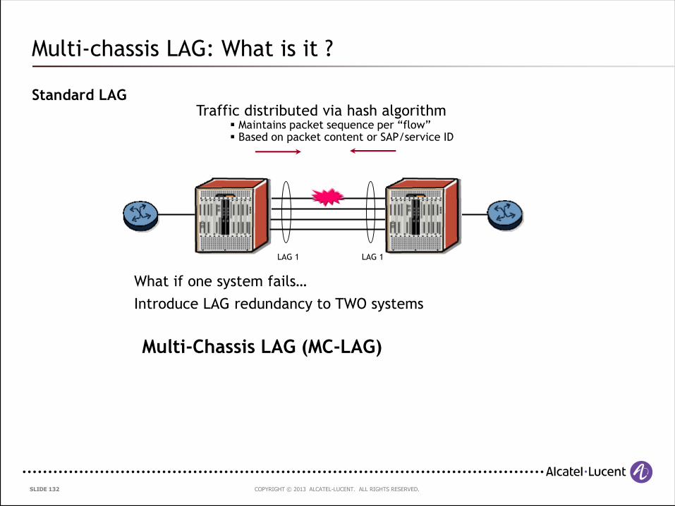
Multi-chassis LAG: What is it ?
LAG 1 LAG 1
Traffic distributed via hash algorithm Maintains packet sequence per “flow” Based on packet content or SAP/service ID
Link Aggregation Control Protocol (LACP)
IEEE Std 802.3-2002_part3 (formerly in 802.3ad)
system MAC and priority system MAC and priority
administrative key administrative key
Consistent port capabilities (e.g. speed, duplex)
Standard LAG
What if one system fails…
Introduce LAG redundancy to TWO systems
Multi-Chassis LAG (MC-LAG)
COPYRIGHT © 2013 ALCATEL-LUCENT. ALL RIGHTS RESERVED. SLIDE 133
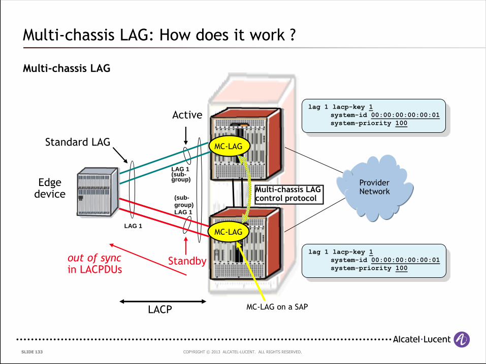
Multi-chassis LAG: How does it work ?
Multi-chassis LAG
LAG 1
Provider Network
lag 1 lacp-key 1
system-id 00:00:00:00:00:01
system-priority 100
lag 1 lacp-key 1
system-id 00:00:00:00:00:01
system-priority 100
Edge device
LAG 1(sub-group)
(sub-
group)
LAG 1
LACP
Standard LAG
Multi-chassis LAG control protocol
MC-LAG
MC-LAG
MC-LAG on a SAP
Active
Standbyout of syncin LACPDUs
COPYRIGHT © 2013 ALCATEL-LUCENT. ALL RIGHTS RESERVED. SLIDE 134
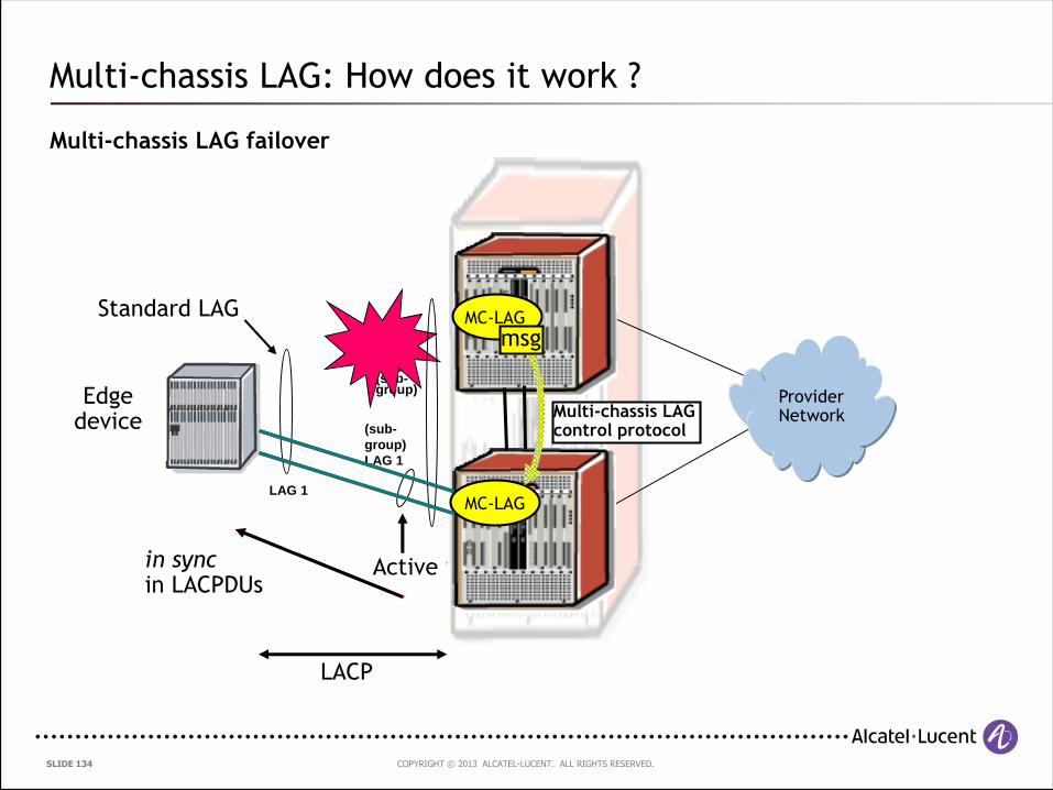
Multi-chassis LAG: How does it work ?
Active
LAG 1(sub-group)
LAG 1
Provider Network
Edge device
LACP
Standard LAG
Standby
Multi-chassis LAG failover
Multi-chassis LAG control protocol
MC-LAG
MC-LAG
msg
(sub-
group)
LAG 1
out of sync LACP message
Activein syncin LACPDUs
COPYRIGHT © 2013 ALCATEL-LUCENT. ALL RIGHTS RESERVED. SLIDE 135
4.7.2 Redundancy with VPLS
COPYRIGHT © 2013 ALCATEL-LUCENT. ALL RIGHTS RESERVED. SLIDE 136
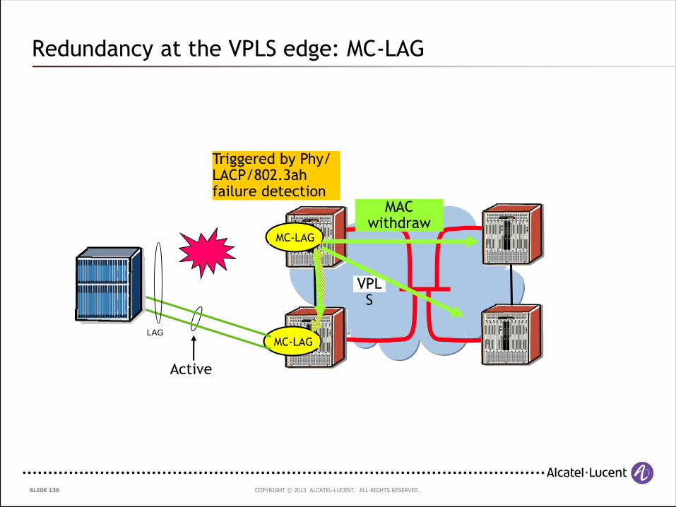
Active
Redundancy at the VPLS edge: MC-LAG
LAG
Standby
MC-LAG
Standard LAG
VPLS
Active
MC-LAG
MAC withdraw
Triggered by Phy/ LACP/802.3ah failure detection
COPYRIGHT © 2013 ALCATEL-LUCENT. ALL RIGHTS RESERVED. SLIDE 137
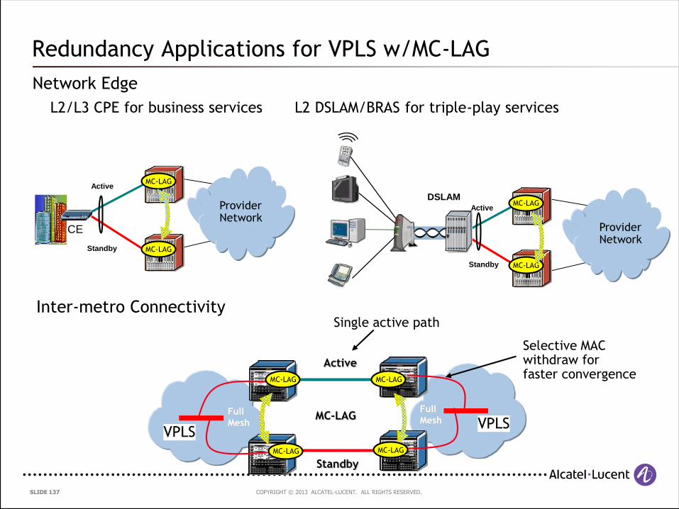
Redundancy Applications for VPLS w/MC-LAG
Network Edge
L2/L3 CPE for business services L2 DSLAM/BRAS for triple-play services
DSLAM
Provider Network
Standby
ActiveProvider Network
Standby
Active
CE
MC-LAG
MC-LAG
MC-LAG
MC-LAG
Full
Mesh
Full
MeshMC-LAG
Active
Standby
MC-LAG
MC-LAG
MC-LAG
MC-LAG
VPLSVPLS
Inter-metro ConnectivitySingle active path
Selective MAC withdraw for faster convergence
COPYRIGHT © 2013 ALCATEL-LUCENT. ALL RIGHTS RESERVED. SLIDE 138
4.7.3 Pseudo-wire Redundancy with Multi-chassis LAG
COPYRIGHT © 2013 ALCATEL-LUCENT. ALL RIGHTS RESERVED. SLIDE 139
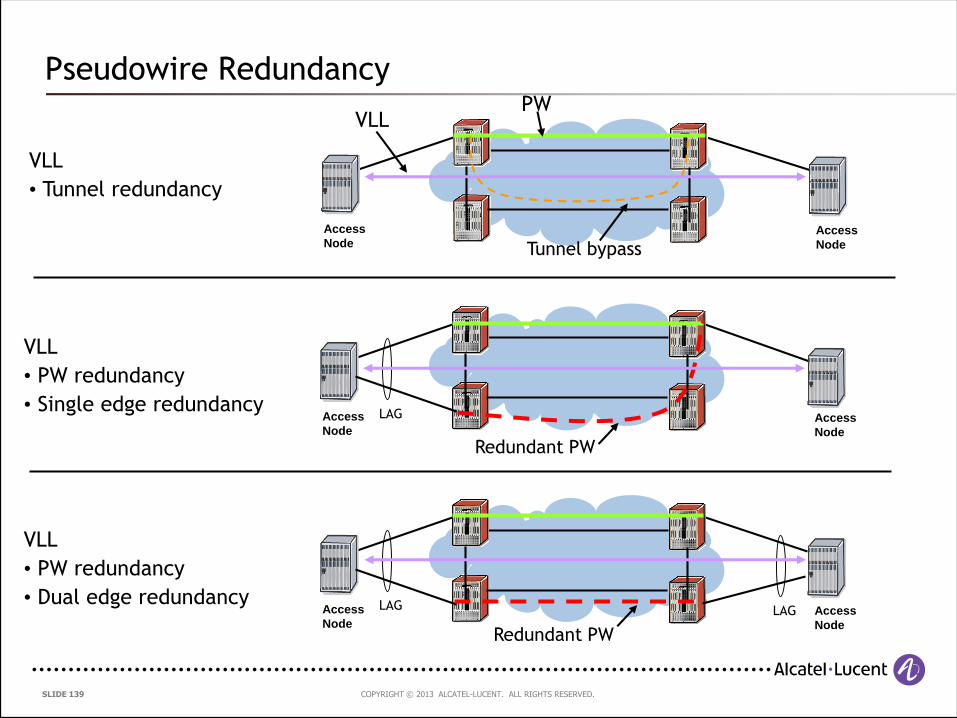
Pseudowire Redundancy
Access
NodeAccess
Node
VLL
• Tunnel redundancy
PW
Tunnel bypass
VLL
Access
NodeAccess
Node
VLL
• PW redundancy
• Single edge redundancyLAG
Redundant PW
Access
NodeAccess
Node
VLL
• PW redundancy
• Dual edge redundancy LAG LAG
Redundant PW

COPYRIGHT © 2013 ALCATEL-LUCENT. ALL RIGHTS RESERVED. SLIDE 140
Combining MC-LAG with Pseudowire Redundancy
Extends L2 point-to-point redundancy across the network
Acces
s NodeAcces
s Node
MC-LAG
Redundant PW
Active Active
Active Standby
Local PW status signaled via T-LDP
VLL service terminates on different devices
MC-LAG status propagatedto local PW end points
PW showing both endsactive preferred for forwarding

COPYRIGHT © 2013 ALCATEL-LUCENT. ALL RIGHTS RESERVED. SLIDE 141
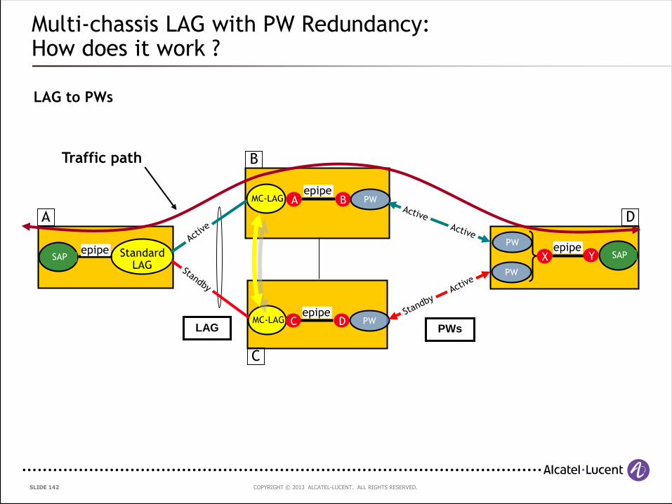
Multi-chassis LAG with Pseudo-Wire Redundancy:How does it work ?
Access
Node
Access
Node
VLL
• PW redundancy
• Single edge redundancy
LAG
PWVLL
COPYRIGHT © 2013 ALCATEL-LUCENT. ALL RIGHTS RESERVED. SLIDE 142
Multi-chassis LAG with PW Redundancy:How does it work ?
LAG to PWs
LAG
MC-LAG
Standard LAG
SAP
MC-LAG
SAP
epipeC
X Y
BA
D
epipe
epipe
PW
PW
PW
PW
Traffic path
epipe
PWs
A
C
B
D
COPYRIGHT © 2013 ALCATEL-LUCENT. ALL RIGHTS RESERVED. SLIDE 143
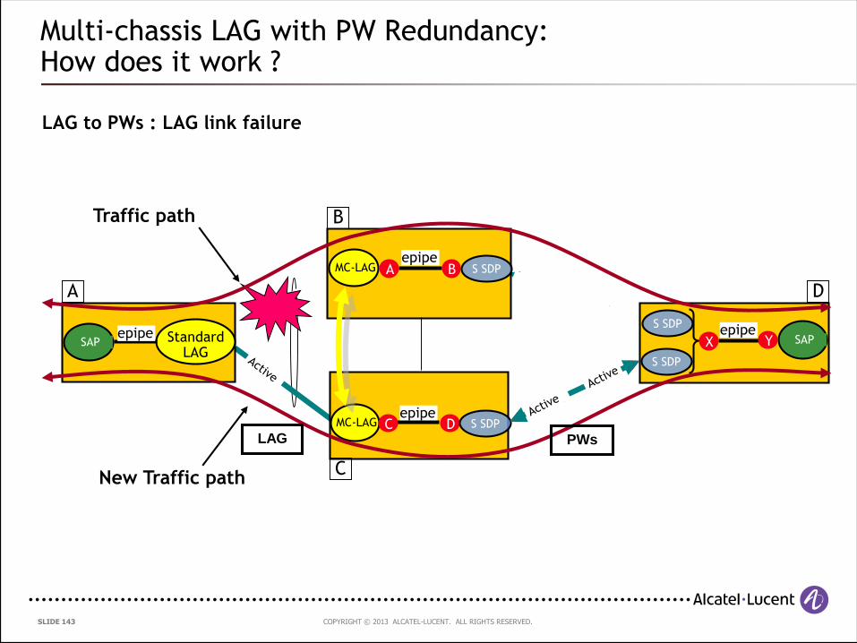
Multi-chassis LAG with PW Redundancy:How does it work ?
LAG to PWs : LAG link failure
MC-LAG
Standard LAG
SAP
MC-LAG
SAP
epipeC
X Y
BA
D
epipe
epipe
S SDP
S SDP
S SDP
S SDP
Traffic path
epipe
New Traffic path
A
C
B
D
LAG PWs
COPYRIGHT © 2013 ALCATEL-LUCENT. ALL RIGHTS RESERVED. SLIDE 144
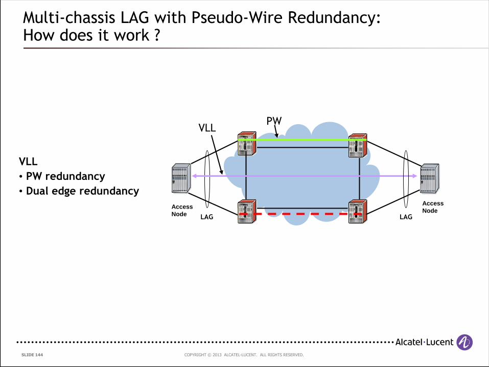
Multi-chassis LAG with Pseudo-Wire Redundancy:How does it work ?
Access
Node
Access
Node
VLL
• PW redundancy
• Dual edge redundancy
LAG
PWVLL
LAG
COPYRIGHT © 2013 ALCATEL-LUCENT. ALL RIGHTS RESERVED. SLIDE 145
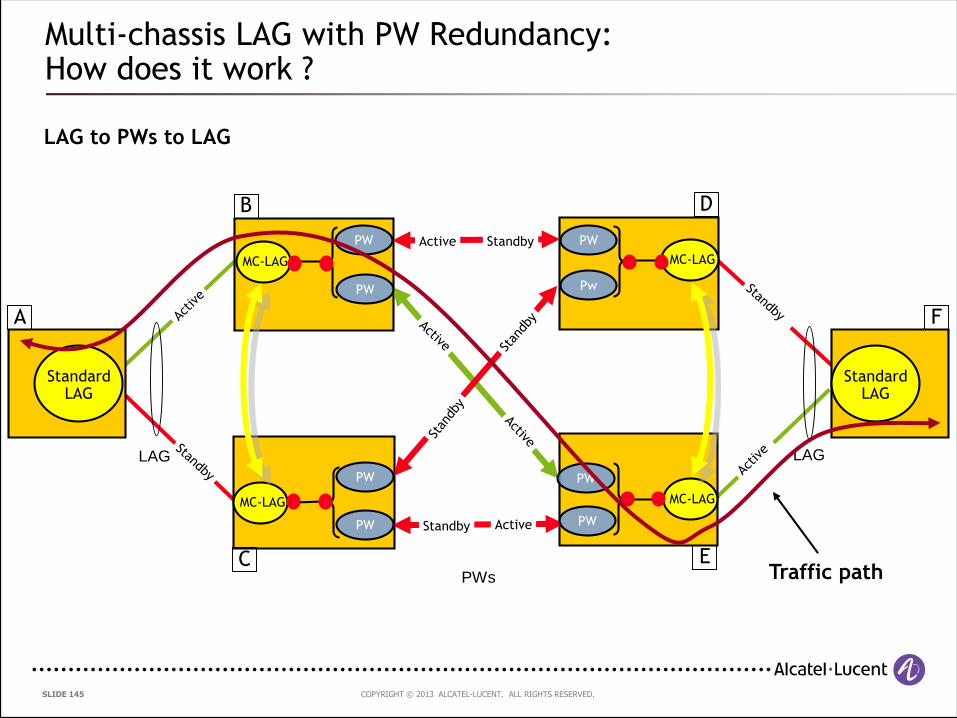
Multi-chassis LAG with PW Redundancy:How does it work ?
LAG to PWs to LAG
LAG LAG
MC-LAG
Standard LAG
MC-LAG MC-LAG
MC-LAG
Active Standby
Active Standby
Standard LAG
PWs
PW
Pw
PW
PW
PW
PW
PW
PW
Traffic path
A F
B D
EC
COPYRIGHT © 2013 ALCATEL-LUCENT. ALL RIGHTS RESERVED. SLIDE 146
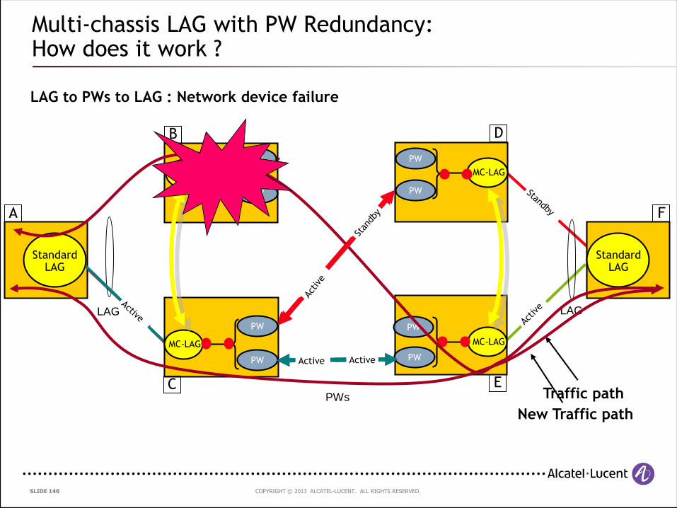
Multi-chassis LAG with PW Redundancy:How does it work ?
LAG to PWs to LAG : Network device failure
Active Standby
LAG LAG
MC-LAG
Standard LAG
MC-LAG MC-LAG
MC-LAG
Active Standby
Standard LAG
PWs
PW
PW
PW
PW
PW
PW
PW
PW
Traffic path
New Traffic path
Active Active
A F
B D
EC
COPYRIGHT © 2013 ALCATEL-LUCENT. ALL RIGHTS RESERVED. SLIDE 147
4.7.4 Multi-segment Pseudo-wires
COPYRIGHT © 2013 ALCATEL-LUCENT. ALL RIGHTS RESERVED. SLIDE 148
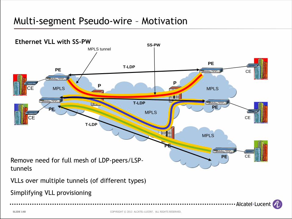
Multi-segment Pseudo-wire – Motivation
Ethernet VLL with SS-PW
CE
CE
CE
CE
CE
MPLS MPLS
MPLS
MPLS
PE
PE
PE
PE
PP
PE
PE
MPLS tunnelSS-PW
T-LDP
T-LDP
T-LDP
Remove need for full mesh of LDP-peers/LSP-
tunnels
VLLs over multiple tunnels (of different types)
Simplifying VLL provisioning
COPYRIGHT © 2013 ALCATEL-LUCENT. ALL RIGHTS RESERVED. SLIDE 149149 | MPLS-based Metro Ethernet Networks, February 2011
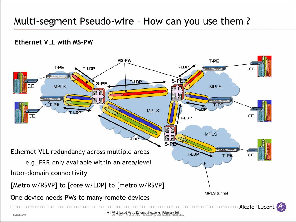
Multi-segment Pseudo-wire – How can you use them ?
Ethernet VLL with MS-PW
CE
CE
CE
CE
CE
MPLS MPLS
MPLS
MPLS tunnel
T-LDP
T-LDP
T-LDP
MPLS
S-PES-PE
T-PEMS-PW
T-PE
T-PE
T-PE
T-LDP
T-LDP
T-LDP
S-PE
T-PE
T-LDP
T-LDP
Ethernet VLL redundancy across multiple areas
e.g. FRR only available within an area/level
Inter-domain connectivity
[Metro w/RSVP] to [core w/LDP] to [metro w/RSVP]
One device needs PWs to many remote devices
COPYRIGHT © 2013 ALCATEL-LUCENT. ALL RIGHTS RESERVED. SLIDE 150
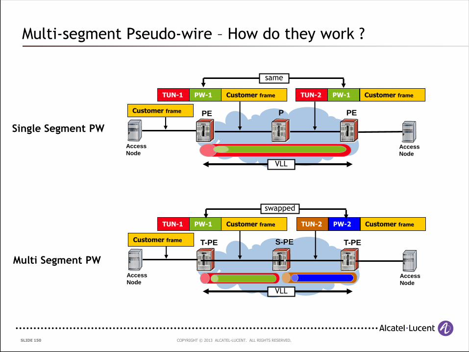
Multi-segment Pseudo-wire – How do they work ?
Customer frame
Customer frame
PE
Access
NodeAccess
Node
PEP
Single Segment PW
VLL
Access
NodeAccess
Node
T-PET-PE S-PE
Multi Segment PW
VLL
Customer frameTUN-1 PW-1 Customer frameTUN-2 PW-2
Customer frameTUN-1 PW-1 Customer frameTUN-2 PW-1
same
swapped
COPYRIGHT © 2013 ALCATEL-LUCENT. ALL RIGHTS RESERVED. SLIDE 151
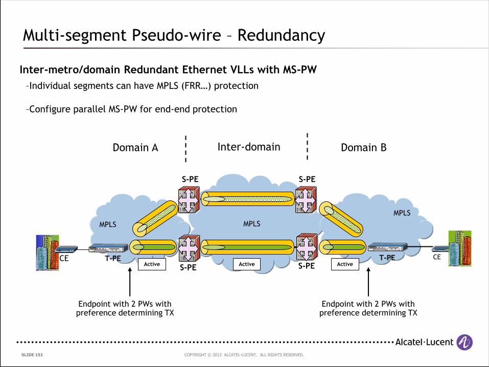
Multi-segment Pseudo-wire – Redundancy
Inter-metro/domain Redundant Ethernet VLLs with MS-PW
CECE
MPLS
MPLS
MPLS
S-PET-PE T-PE
S-PEActive Active Active
Endpoint with 2 PWs with preference determining TX
Endpoint with 2 PWs with preference determining TX
S-PES-PE
Domain A Domain BInter-domain
–Individual segments can have MPLS (FRR…) protection
–Configure parallel MS-PW for end-end protection

COPYRIGHT © 2013 ALCATEL-LUCENT. ALL RIGHTS RESERVED. SLIDE 152
5. Summary
COPYRIGHT © 2013 ALCATEL-LUCENT. ALL RIGHTS RESERVED. SLIDE 153
Summary
Ethernet Services are in a period of tremendous growth with great
revenue potential for service providers
The Metro Ethernet Forum has standardised Ethernet services and
continues to enhance specifications
Traditional forms of Ethernet delivery are no longer suitable for the
delivery of “carrier-grade” Ethernet services
MPLS provides a proven platform for the delivery of scalable, flexible,
feature-rich Ethernet services using the same infrastructure used to
deliver other MPLS-based services

COPYRIGHT © 2013 ALCATEL-LUCENT. ALL RIGHTS RESERVED. SLIDE 154
6. Questions ???

COPYRIGHT © 2013 ALCATEL-LUCENT. ALL RIGHTS RESERVED. SLIDE 155
Thank You

COPYRIGHT © 2013 ALCATEL-LUCENT. ALL RIGHTS RESERVED. SLIDE 156
www.alcatel-lucent.com