motorised pulley solves dirt conveyor problem at uk … · motorised pulley solves dirt conveyor...
TRANSCRIPT
23rd Annual International Coal Preparation & Aggregate Processing Exhibition & Conference Lexington, KY; May 2-4, 2006
1
MOTORISED PULLEY SOLVES DIRT CONVEYOR PROBLEM AT UK COAL COLLIERY
S. Pringle
Head of Coal Preparation, UK Coal Ltd M. Barry
Coal Preparation Manager, UK Coal Ltd Kellingley Colliery M. Gawinski
President, Rulmeca Corporation
ABSTRACT Beginning with an historical sketch of the UK Coal industry this paper highlights the technical blessings and burdens of that industry’s long life. The paper explains how UK Coal’s Kelling-ley Colliery reduced unscheduled production stoppages and decreased maintenance and energy expense by upgrading their floor-mounted “bottom-belt” conveyor drive system. Specific de-tails on the new Motorised Pulley belt drive are presented.
BACKGROUND
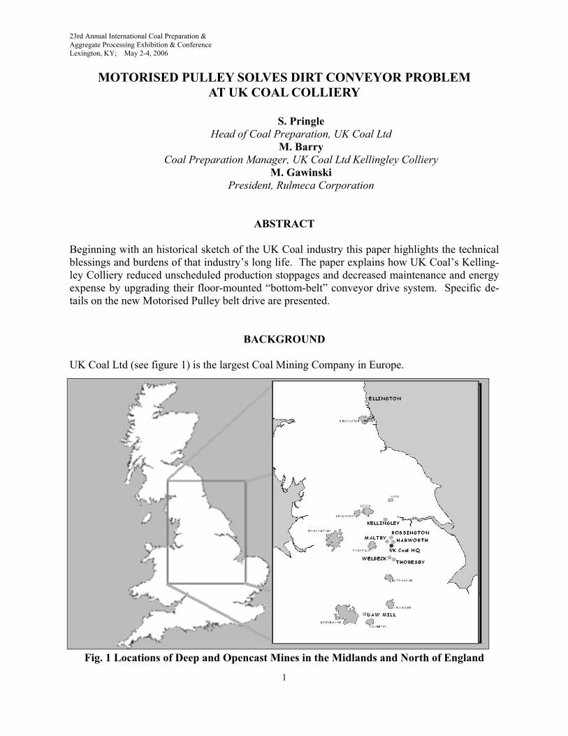
UK Coal Ltd (see figure 1) is the largest Coal Mining Company in Europe.
Fig. 1 Locations of Deep and Opencast Mines in the Midlands and North of England
23rd Annual International Coal Preparation & Aggregate Processing Exhibition & Conference Lexington, KY; May 2-4, 2006
11
RULMECA MOTORISED PULLEY INSTALLATION AT UK COAL’S KELLINGLEY COLLIERY, OCTOBER 2003
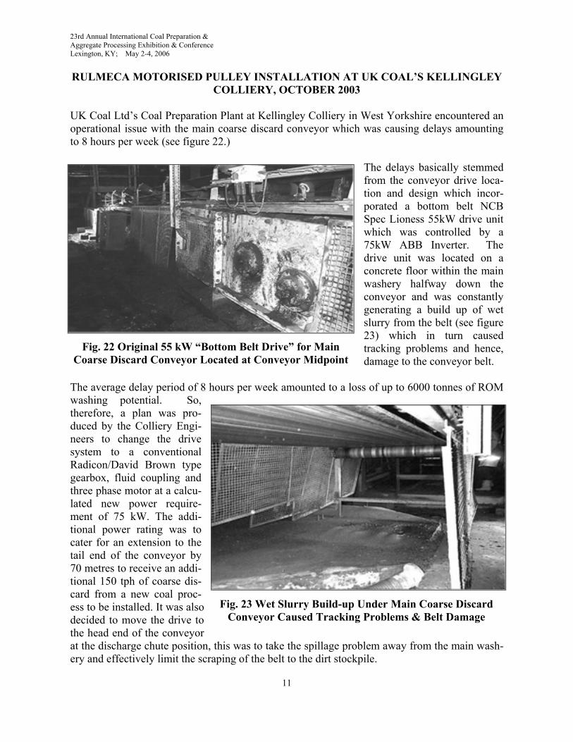
UK Coal Ltd’s Coal Preparation Plant at Kellingley Colliery in West Yorkshire encountered an operational issue with the main coarse discard conveyor which was causing delays amounting to 8 hours per week (see figure 22.)
The delays basically stemmed from the conveyor drive loca-tion and design which incor-porated a bottom belt NCB Spec Lioness 55kW drive unit which was controlled by a 75kW ABB Inverter. The drive unit was located on a concrete floor within the main washery halfway down the conveyor and was constantly generating a build up of wet slurry from the belt (see figure 23) which in turn caused tracking problems and hence, damage to the conveyor belt.
The average delay period of 8 hours per week amounted to a loss of up to 6000 tonnes of ROM washing potential. So, therefore, a plan was pro-duced by the Colliery Engi-neers to change the drive system to a conventional Radicon/David Brown type gearbox, fluid coupling and three phase motor at a calcu-lated new power require-ment of 75 kW. The addi-tional power rating was to cater for an extension to the tail end of the conveyor by 70 metres to receive an addi-tional 150 tph of coarse dis-card from a new coal proc-ess to be installed. It was also decided to move the drive to the head end of the conveyor at the discharge chute position, this was to take the spillage problem away from the main wash-ery and effectively limit the scraping of the belt to the dirt stockpile.
Fig. 22 Original 55 kW “Bottom Belt Drive” for Main Coarse Discard Conveyor Located at Conveyor Midpoint
Fig. 23 Wet Slurry Build-up Under Main Coarse Discard Conveyor Caused Tracking Problems & Belt Damage
23rd Annual International Coal Preparation & Aggregate Processing Exhibition & Conference Lexington, KY; May 2-4, 2006
12
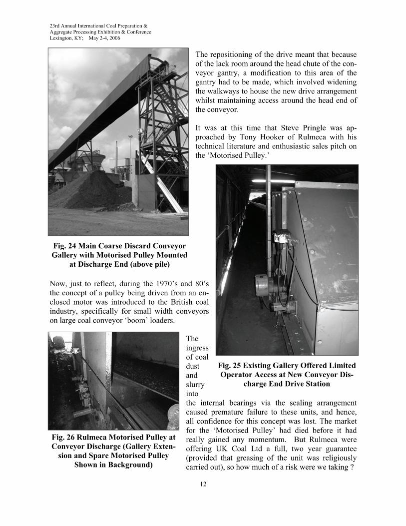
The repositioning of the drive meant that because of the lack room around the head chute of the con-veyor gantry, a modification to this area of the gantry had to be made, which involved widening the walkways to house the new drive arrangement whilst maintaining access around the head end of the conveyor. It was at this time that Steve Pringle was ap-proached by Tony Hooker of Rulmeca with his technical literature and enthusiastic sales pitch on the ‘Motorised Pulley.’
Now, just to reflect, during the 1970’s and 80’s the concept of a pulley being driven from an en-closed motor was introduced to the British coal industry, specifically for small width conveyors on large coal conveyor ‘boom’ loaders.
The ingress of coal dust and slurry into the internal bearings via the sealing arrangement caused premature failure to these units, and hence, all confidence for this concept was lost. The market for the ‘Motorised Pulley’ had died before it had really gained any momentum. But Rulmeca were offering UK Coal Ltd a full, two year guarantee (provided that greasing of the unit was religiously carried out), so how much of a risk were we taking ?
Fig. 24 Main Coarse Discard Conveyor Gallery with Motorised Pulley Mounted
at Discharge End (above pile)
Fig. 25 Existing Gallery Offered Limited Operator Access at New Conveyor Dis-
charge End Drive Station
Fig. 26 Rulmeca Motorised Pulley at Conveyor Discharge (Gallery Exten-
sion and Spare Motorised Pulley Shown in Background)
23rd Annual International Coal Preparation & Aggregate Processing Exhibition & Conference Lexington, KY; May 2-4, 2006
13
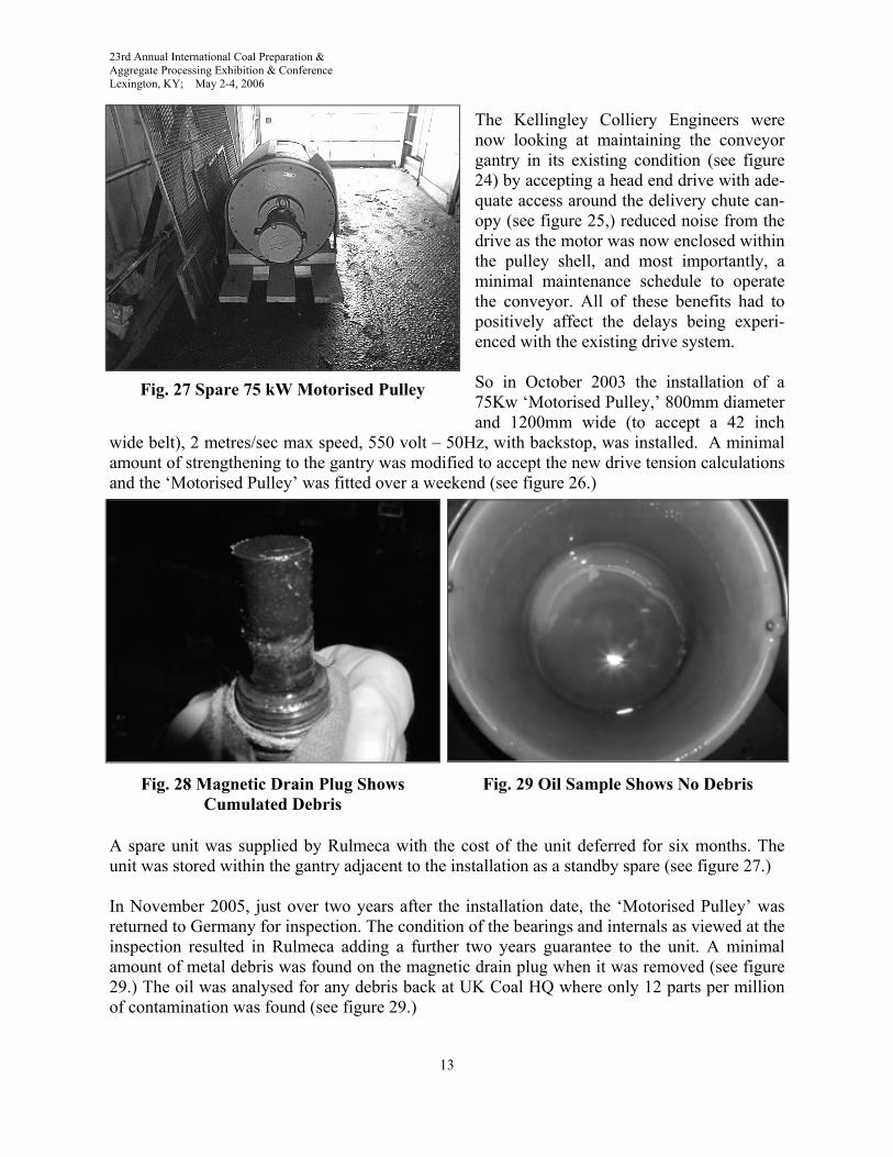
The Kellingley Colliery Engineers were now looking at maintaining the conveyor gantry in its existing condition (see figure 24) by accepting a head end drive with ade-quate access around the delivery chute can-opy (see figure 25,) reduced noise from the drive as the motor was now enclosed within the pulley shell, and most importantly, a minimal maintenance schedule to operate the conveyor. All of these benefits had to positively affect the delays being experi-enced with the existing drive system. So in October 2003 the installation of a 75Kw ‘Motorised Pulley,’ 800mm diameter and 1200mm wide (to accept a 42 inch
wide belt), 2 metres/sec max speed, 550 volt – 50Hz, with backstop, was installed. A minimal amount of strengthening to the gantry was modified to accept the new drive tension calculations and the ‘Motorised Pulley’ was fitted over a weekend (see figure 26.)
A spare unit was supplied by Rulmeca with the cost of the unit deferred for six months. The unit was stored within the gantry adjacent to the installation as a standby spare (see figure 27.) In November 2005, just over two years after the installation date, the ‘Motorised Pulley’ was returned to Germany for inspection. The condition of the bearings and internals as viewed at the inspection resulted in Rulmeca adding a further two years guarantee to the unit. A minimal amount of metal debris was found on the magnetic drain plug when it was removed (see figure 29.) The oil was analysed for any debris back at UK Coal HQ where only 12 parts per million of contamination was found (see figure 29.)
Fig. 27 Spare 75 kW Motorised Pulley
Fig. 29 Oil Sample Shows No Debris Fig. 28 Magnetic Drain Plug Shows Cumulated Debris
23rd Annual International Coal Preparation & Aggregate Processing Exhibition & Conference Lexington, KY; May 2-4, 2006
14
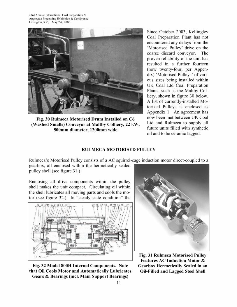
Since October 2003, Kellingley Coal Preparation Plant has not encountered any delays from the ‘Motorised Pulley’ drive on the coarse discard conveyor. The proven reliability of the unit has resulted in a further fourteen (now twenty-four, per Appen-dix) ‘Motorised Pulleys’ of vari-ous sizes being installed within UK Coal Ltd Coal Preparation Plants, such as the Maltby Col-liery, shown in figure 30 below. A list of currently-installed Mo-torized Pulleys is enclosed as Appendix 1. An agreement has now been met between UK Coal Ltd and Rulmeca to supply all future units filled with synthetic oil and to be ceramic lagged.
RULMECA MOTORISED PULLEY
Rulmeca’s Motorised Pulley consists of a AC squirrel-cage induction motor direct-coupled to a gearbox, all enclosed within the hermetically sealed pulley shell (see figure 31.) Enclosing all drive components within the pulley shell makes the unit compact. Circulating oil within the shell lubricates all moving parts and cools the mo-tor (see figure 32.) In “steady state condition” the
Fig. 30 Rulmeca Motorised Drum Installed on C6 (Washed Smalls) Conveyor at Maltby Colliery, 22 kW,
500mm diameter, 1200mm wide
Fig. 31 Rulmeca Motorised Pulley Features AC Induction Motor &
Gearbox Hermetically Sealed in an Oil-Filled and Lagged Steel Shell
Fig. 32 Model 800H Internal Components. Note that Oil Cools Motor and Automatically Lubricates
Gears & Bearings (incl. Main Support Bearings)
23rd Annual International Coal Preparation & Aggregate Processing Exhibition & Conference Lexington, KY; May 2-4, 2006
15
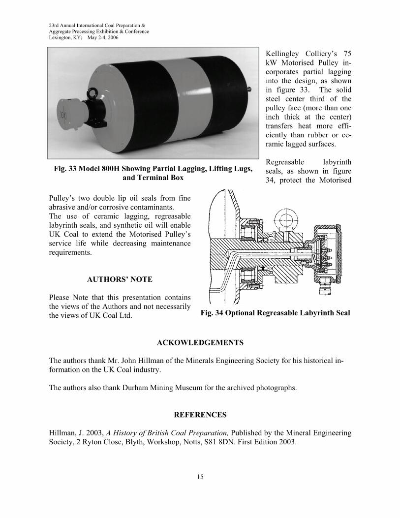
Kellingley Colliery’s 75 kW Motorised Pulley in-corporates partial lagging into the design, as shown in figure 33. The solid steel center third of the pulley face (more than one inch thick at the center) transfers heat more effi-ciently than rubber or ce-ramic lagged surfaces. Regreasable labyrinth seals, as shown in figure 34, protect the Motorised
Pulley’s two double lip oil seals from fine abrasive and/or corrosive contaminants. The use of ceramic lagging, regreasable labyrinth seals, and synthetic oil will enable UK Coal to extend the Motorised Pulley’s service life while decreasing maintenance requirements.
AUTHORS’ NOTE Please Note that this presentation contains the views of the Authors and not necessarily the views of UK Coal Ltd.
ACKOWLEDGEMENTS
The authors thank Mr. John Hillman of the Minerals Engineering Society for his historical in-formation on the UK Coal industry. The authors also thank Durham Mining Museum for the archived photographs.
REFERENCES
Hillman, J. 2003, A History of British Coal Preparation, Published by the Mineral Engineering Society, 2 Ryton Close, Blyth, Workshop, Notts, S81 8DN. First Edition 2003.
Fig. 33 Model 800H Showing Partial Lagging, Lifting Lugs, and Terminal Box
Fig. 34 Optional Regreasable Labyrinth Seal
23rd Annual International Coal Preparation & Aggregate Processing Exhibition & Conference Lexington, KY; May 2-4, 2006
16
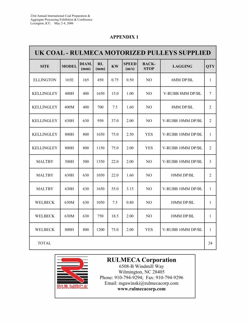
UK COAL - RULMECA MOTORIZED PULLEYS SUPPLIED
SITE MODEL DIAM. (mm)
RL (mm) KW SPEED
(m/s) BACK-STOP LAGGING QTY
ELLINGTON 165E 165 450 0.75 0.50 NO 6MM DP/BL 1
KELLINGLEY 400H 400 1650 15.0 1.00 NO V-RUBB 8MM DP/BL 7
KELLINGLEY 400M 400 700 7.5 1.60 NO 8MM DP/BL 2
KELLINGLEY 630H 630 950 37.0 2.00 NO V-RUBB 10MM DP/BL 2
KELLINGLEY 800H 800 1650 75.0 2.50 YES V-RUBB 10MM DP/BL 1
KELLINGLEY 800H 800 1150 75.0 2.00 YES V-RUBB 10MM DP/BL 2
MALTBY 500H 500 1350 22.0 2.00 NO V-RUBB 10MM DP/BL 3
MALTBY 630H 630 1050 22.0 1.60 NO 10MM DP/BL 2
MALTBY 630H 630 1650 55.0 3.15 NO V-RUBB 10MM DP/BL 1
WELBECK 630M 630 1050 7.5 0.80 NO 10MM DP/BL 1
WELBECK 630M 630 750 18.5 2.00 NO 10MM DP/BL 1
WELBECK 800H 800 1200 75.0 2.00 YES V-RUBB 10MM DP/BL 1
24 TOTAL
APPENDIX 1
RULMECA Corporation 6508-B Windmill Way Wilmington, NC 28405
Phone: 910-794-9294; Fax: 910-794-9296 Email: [email protected]
www.rulmecacorp.com