motor operated valves
DESCRIPTION
electricalTRANSCRIPT
QURAYYAH COMBINED CYCLE POWER PLANT
MECHANICAL MAINTENANCE TRAINING
Motor Operated Valves

TABLE OF CONTENTS
QCCPP (MOTOR OPERATED VALVES - MECHANICAL) 1
Table of Contents
Description Page Number
Pacing Schedule
Abbreviations
1.0 General
1.1 Purpose ................................................................................................................................ 9
1.2 References ........................................................................................................................... 9
1.3 Safety ................................................................................................................................. 10
1.4 Terminal Objectives ........................................................................................................... 11
1.5 Overview ............................................................................................................................ 12
2.0 Valves .............................................................................................................................................. 15
2.1 Types of Valves .................................................................................................................. 17
2.2 Motor Operated Valves at the QCCPP ............................................................................... 24
2.3 Piping and Instrumentation Diagrams .............................................................................. 25
2.4 Rigging, Handling, Storage & Installation of Valves ........................................................... 29
3.0 Valve Actuators .............................................................................................................................. 29
3.1Valve Actuators ................................................................................................................... 33
3.2 Rotorik Actuator ................................................................................................................. 35
3.3 Limitorque Actuator ........................................................................................................... 43
3.4 EIM Actuator ...................................................................................................................... 51
4.0 Task Sheets ..................................................................................................................................... 61
LIST OF FIGURES
2 QCCPP (MOTOR OPERATED VALVES - MECHANICAL)
LIST OF FIGURES
Description Page Number
Figure 1: Description of Manual/Operation ............................................................................ 13
Figure 2 : Hammer Blow Effect ................................................................................................ 14
Figure 3: Gate Valve ................................................................................................................. 17
Figure 4: Gate Valve Operating Positions ................................................................................ 18
Figure 5: Globe Valve ............................................................................................................... 18
Figure 6: Globe Valve Operating Positions .............................................................................. 19
Figure 7: Ball Valves ................................................................................................................. 19
Figure 8: Ball Valve Operating Positions .................................................................................. 20
Figure 9: Ball Valve Operating Positions .................................................................................. 20
Figure 10: Butterfly Valve ........................................................................................................ 21
Figure 11: Butterfly Valve Operating Procedure ..................................................................... 21
Figure 12: Diaphragm Valves ................................................................................................... 22
Figure 13: Diaphragm Valve Operating Positions .................................................................... 22
Figure 14: Fluid direction ......................................................................................................... 23
Figure 15: Main Parts of a Check Valve ................................................................................... 23
Figure 16: Swing Check Valve Operating Positions .................................................................. 23
Figure 17: Piping & Instrumentation Diagram of MOVs for Fuel Oil System .......................... 25
Figure 18: Piping and Instrumentation Diagram of MOVs for Raw Water .............................. 27
Figure 19: Rigging, Handling, Storage & Installation for a Ball Valve and Actuator ................ 29
Figure 20: Electric Motor Actuator .......................................................................................... 33
Figure 21: Parts list (a) ............................................................................................................ 38
Figure 22: Parts List (b) ........................................................................................................... 38
Figure 23: Parts list (c) ............................................................................................................. 39
Figure 24: MX actuator base .................................................................................................... 47
Figure 25: MX Actuator Base (b) .............................................................................................. 48
LIST OF FIGURES
QCCPP (MOTOR OPERATED VALVES - MECHANICAL) 3
LIST OF FIGURES
Description Page Number
Figure 26: Exploded view of Actuator Base ............................................................................. 48
Figure 27: B1 Base .................................................................................................................... 49
Figure 28 Exploded View of B1 Base ........................................................................................ 50
Figure 29: Cut‐ Away View of Stem Nut .................................................................................. 54
Figure 30: Exploded View of Thrust Base Parts Including Bearing Assembly .......................... 54
Figure 31: Parts of EIM Electric Actuator ................................................................................. 55
Figure 32: Motors and Spur Gears ........................................................................................... 57
Figure 33: Splined Mounted Gear ............................................................................................ 57
Figure 34: Motor Gear Assembly ............................................................................................. 57
Figure 35: Thermal Overload Protection Diagram ................................................................... 57
Figure 36: Clutch Lever Assembly ............................................................................................ 58
Figure 37: Clutch Spool ............................................................................................................ 58
Figure 38: Pad lockable Clutch Lever ....................................................................................... 58
Figure 39: Main Drive Gear ...................................................................................................... 58
Figure 40: Worm and Clutch Assembly .................................................................................... 59
Figure 41: Clutch Shaft Splined Connection ............................................................................ 59
Figure 42: Splined Drive Bushing ............................................................................................. 59
Figure 43: Torque Limit and Geared Limit Drive Assembly ..................................................... 60
Figure 44: Limit Switch Gear Box ............................................................................................. 60
LIST OF TABLES
4 QCCPP (MOTOR OPERATED VALVES - MECHANICAL)
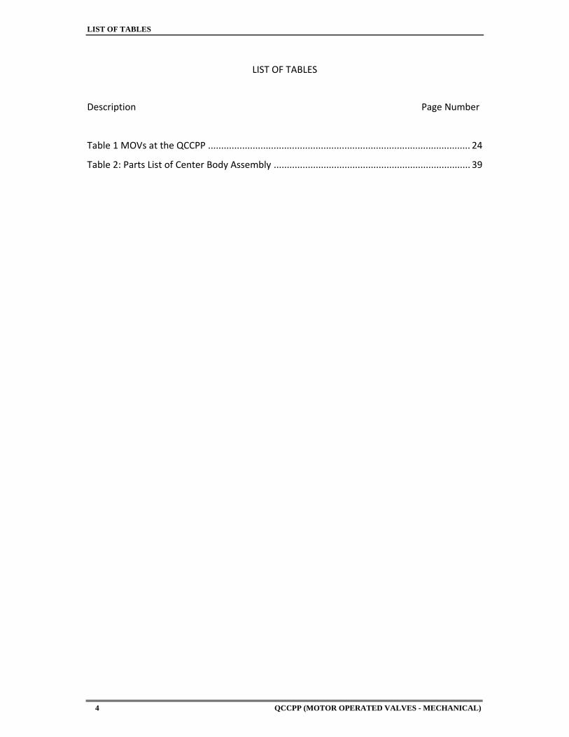
LIST OF TABLES
Description Page Number
Table 1 MOVs at the QCCPP .................................................................................................... 24
Table 2: Parts List of Center Body Assembly ........................................................................... 39
PACING SCHEDULE
QCCPP (MOTOR OPERATED VALVES - MECHANICAL) 5
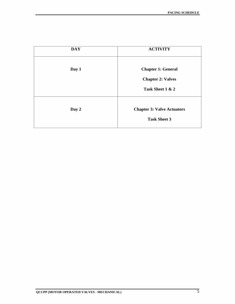
DAY ACTIVITY
Day 1
Chapter 1: General
Chapter 2: Valves
Task Sheet 1 & 2
Day 2
Chapter 3: Valve Actuators
Task Sheet 3
ABBREVIATIONS
QCCPP (MOTOR OPERATED VALVES - MECHANICAL) 6
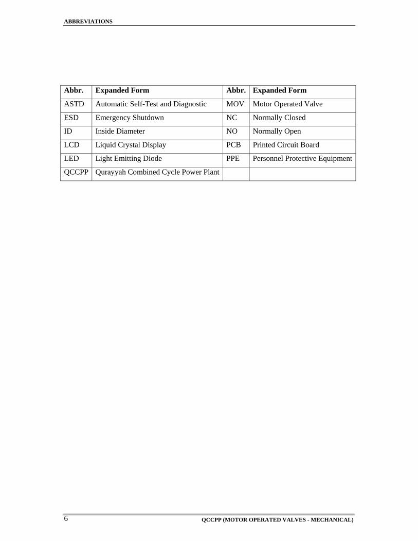
Abbr. Expanded Form Abbr. Expanded Form
ASTD Automatic Self-Test and Diagnostic MOV Motor Operated Valve
ESD Emergency Shutdown NC Normally Closed
ID Inside Diameter NO Normally Open
LCD Liquid Crystal Display PCB Printed Circuit Board
LED Light Emitting Diode PPE Personnel Protective Equipment
QCCPP Qurayyah Combined Cycle Power Plant
QCCPP (MOTOR OPERATED VALVES - MECHANICAL) 7
CHAPTER 1
GENERAL

QCCPP (MOTOR OPERATED VALVES - MECHANICAL) 8
QCCPP (MOTOR OPERATED VALVES - MECHANICAL) 9
GENERAL
1.1 Purpose
The purpose of this manual is to provide specific information to the Qurayyah Combined
Cycle Power Plant Maintenance Personnel regarding the Motor Operated Valves installed at
the Qurayyah Combined Cycle Power Plant. Although this document will convey a good
knowledge and direction concerning the Motor Operated Valves, it is recommended that the
personnel should also consult the Original Equipment Manufacturer’s Instruction Book.
1.2 References
1. Limitorque MX Electronic Actuator FCD LMENIM2306-02 – 9/08 (Installation,
Operation, Maintenance).
2. EIM TECH 2000 ELECTRONIC VALVE ACTUATORS Engineering & Controls
Manual
3. ROTORIK FLUID SYSTEMS, Installation and Maintenance Manual.
QCCPP (MOTOR OPERATED VALVES - MECHANICAL) 10
1.3 Safety
Before the commencement of any maintenance work, the person in charge of the work site is
to perform the job scope activities, described within the work permit. This includes
identifying, recognizing and understanding the potential hazards associated with the work.
Perform his work in the safe working practices in accordance with the safety manual and the
manufacturer’s instruction manual to prevent personal injury and/or equipment damage.
Prior to the commencement of actual work, the person carrying out the work is to make a
safety check based on the above mentioned instructions also use his own judgment to ensure
that the equipment and the prevailing working conditions are safe. During maintenance work,
every employee should follow the safe working procedures detailed in the plant safety
manual.
QCCPP (MOTOR OPERATED VALVES - MECHANICAL) 11
1.4 Terminal Objectives
In a training environment, given the required lectures and demonstrations, instructional
materials and tools, and the references needed, the trainee will be able to:
Describe the construction and explain the principle of operation of the different
actuators used in Qurayyah Power Plant.
1. Rotorik Actuators
2. Limitorque Actuators
3. EIM Actuators
Explain the functions, operation and indication of limit switches assemblies for each
type of MOV actuator and various constructional features of limit switches.
Be able to explain the operating principle and control of the different types of
actuators; Rotorik, Limitorque, and EIM.
Be able to discuss the MOV remote position indicator setting and adjustment.
Trace and analyze circuit, and troubleshoot abnormal indications and operations of
motor - operated valves.
QCCPP (MOTOR OPERATED VALVES - MECHANICAL) 12
1.5 Overview
1.5.1 Valve Functions
Valves are installed in a system to achieve the following functions:
a) Isolation of equipment
b) Regulation of flow and pressure
c) Prevention of reverse flow
d) Prevention of system over-pressurization
1.5.2 Major components
The major components of a valve are:
a) The valve body; in which an aperture of the desired size and shape is provided, depending
upon the function of the valve.
b) The valve stem, a moving component, the operation of which will control the opening or
closing of the aperture in the valve body.
c) The actuator; to control the movement of the stem according to the system requirement.
The actuation may be manual by a hand wheel, power operated by a pneumatic or an electric
actuator or self-regulating against a present spring.
QCCPP (MOTOR OPERATED VALVES - MECHANICAL) 13
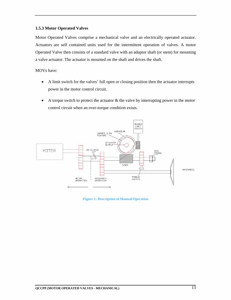
1.5.3 Motor Operated Valves
Motor Operated Valves comprise a mechanical valve and an electrically operated actuator.
Actuators are self contained units used for the intermittent operation of valves. A motor
Operated Valve then consists of a standard valve with an adaptor shaft (or stem) for mounting
a valve actuator. The actuator is mounted on the shaft and drives the shaft.
MOVs have:
A limit switch for the valves’ full open or closing position then the actuator interrupts
power in the motor control circuit.
A torque switch to protect the actuator & the valve by interrupting power in the motor
control circuit when an over-torque condition exists.
Figure 1: Description of Manual/Operation
QCCPP (MOTOR OPERATED VALVES - MECHANICAL) 14
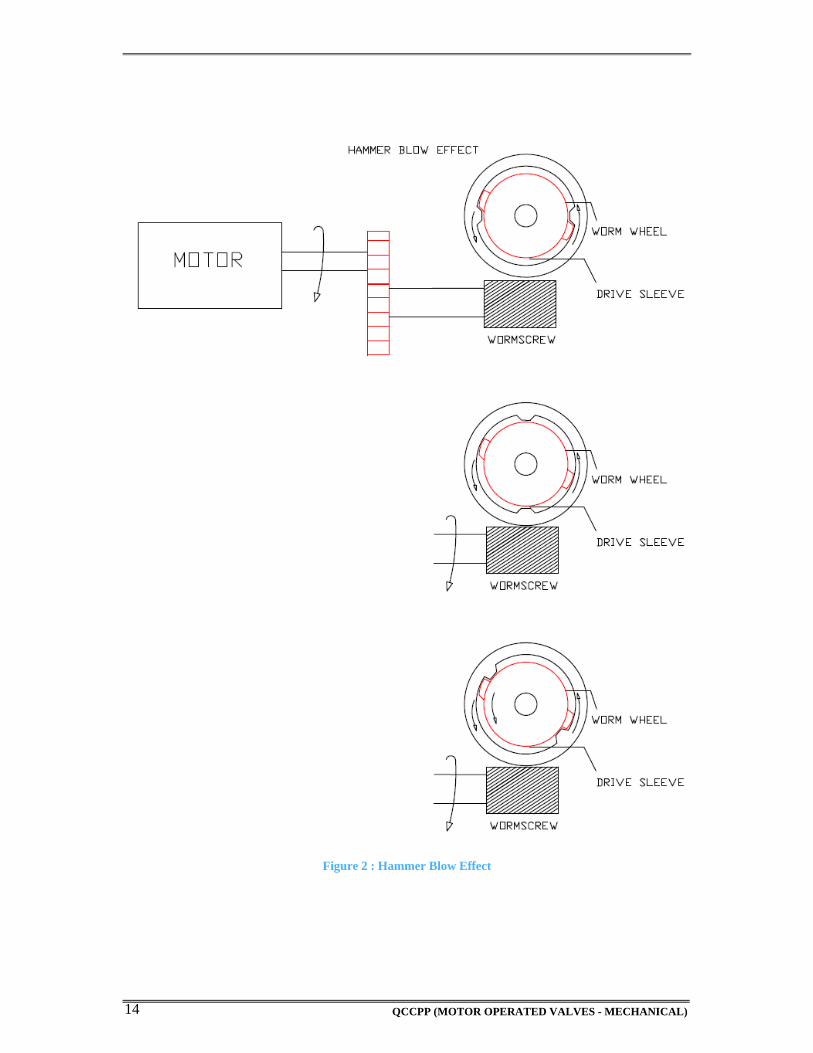
Figure 2 : Hammer Blow Effect
QCCPP (MOTOR OPERATED VALVES - MECHANICAL) 15
CHAPTER 2
VALVES

QCCPP (MOTOR OPERATED VALVES - MECHANICAL) 16
QCCPP (MOTOR OPERATED VALVES - MECHANICAL) 17
2.1 TYPES OF VALVES
* Gate Valves
* Globe Valves
* Ball Valves
* Butterfly Valves
* Diaphragm Valves
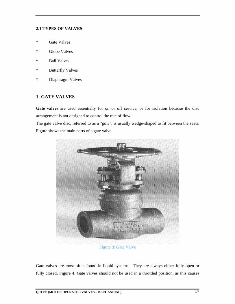
1- GATE VALVES Gate valves are used essentially for on or off service, or for isolation because the disc
arrangement is not designed to control the rate of flow.
The gate valve disc, referred to as a "gate", is usually wedge-shaped to fit between the seats.
Figure shows the main parts of a gate valve.
Figure 3: Gate Valve
Gate valves are most often found in liquid systems. They are always either fully open or
fully closed, Figure 4. Gate valves should not be used in a throttled position, as this causes
QCCPP (MOTOR OPERATED VALVES - MECHANICAL) 18
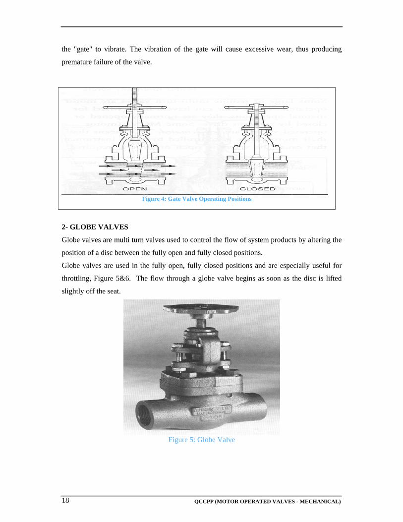
the "gate" to vibrate. The vibration of the gate will cause excessive wear, thus producing
premature failure of the valve.
Figure 4: Gate Valve Operating Positions
2- GLOBE VALVES
Globe valves are multi turn valves used to control the flow of system products by altering the
position of a disc between the fully open and fully closed positions.
Globe valves are used in the fully open, fully closed positions and are especially useful for
throttling, Figure 5&6. The flow through a globe valve begins as soon as the disc is lifted
slightly off the seat.
Figure 5: Globe Valve
QCCPP (MOTOR OPERATED VALVES - MECHANICAL) 19
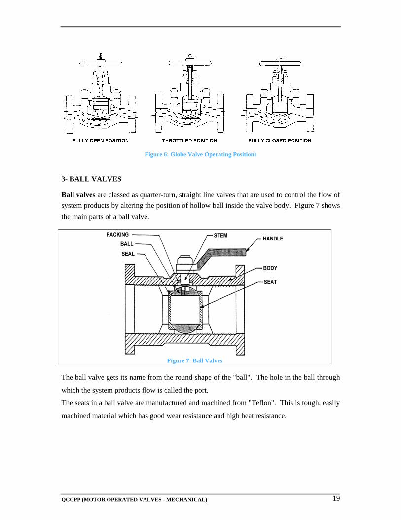
Figure 6: Globe Valve Operating Positions 3- BALL VALVES
Ball valves are classed as quarter-turn, straight line valves that are used to control the flow of
system products by altering the position of hollow ball inside the valve body. Figure 7 shows
the main parts of a ball valve.
Figure 7: Ball Valves
The ball valve gets its name from the round shape of the "ball". The hole in the ball through
which the system products flow is called the port.
The seats in a ball valve are manufactured and machined from "Teflon". This is tough, easily
machined material which has good wear resistance and high heat resistance.
QCCPP (MOTOR OPERATED VALVES - MECHANICAL) 20
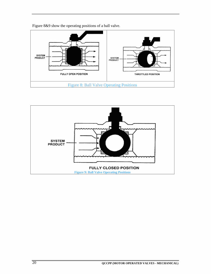
Figure 8&9 show the operating positions of a ball valve.
Figure 8: Ball Valve Operating Positions
Figure 9: Ball Valve Operating Positions
QCCPP (MOTOR OPERATED VALVES - MECHANICAL) 21
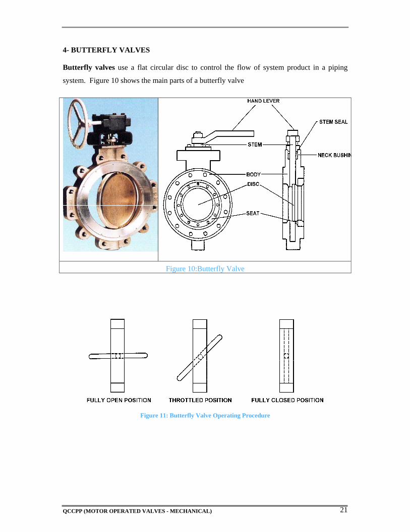
4- BUTTERFLY VALVES Butterfly valves use a flat circular disc to control the flow of system product in a piping
system. Figure 10 shows the main parts of a butterfly valve
Figure 10:Butterfly Valve
Figure 11: Butterfly Valve Operating Procedure
QCCPP (MOTOR OPERATED VALVES - MECHANICAL) 22
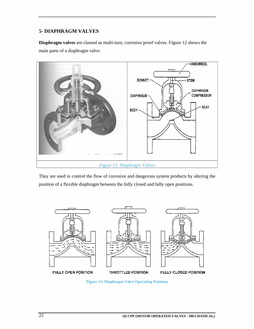
5- DIAPHRAGM VALVES Diaphragm valves are classed as multi-turn, corrosive proof valves. Figure 12 shows the
main parts of a diaphragm valve.
Figure 12: Diaphragm Valves They are used to control the flow of corrosive and dangerous system products by altering the
position of a flexible diaphragm between the fully closed and fully open positions.
Figure 13: Diaphragm Valve Operating Positions
QCCPP (MOTOR OPERATED VALVES - MECHANICAL) 23
Many diaphragm valves are lined with plastic to protect the bore of the valve body from
corrosive system products.
The flexible diaphragm and the body liner are made from a wide range of materials. This is to
cover the wide range of corrosive and dangerous system products used in plant processes.
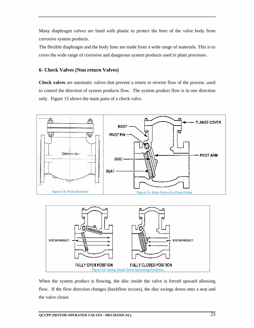
6- Check Valves (Non return Valves) Check valves are automatic valves that prevent a return or reverse flow of the process .used
to control the direction of system products flow. The system product flow is in one direction
only. Figure 15 shows the main parts of a check valve.
Figure 14: Fluid direction
Figure 15: Main Parts of a Check Valve
Figure 16: Swing Check Valve Operating Positions
When the system product is flowing, the disc inside the valve is forced upward allowing
flow. If the flow direction changes (backflow occurs), the disc swings down onto a seat and
the valve closes
QCCPP (MOTOR OPERATED VALVES - MECHANICAL) 24
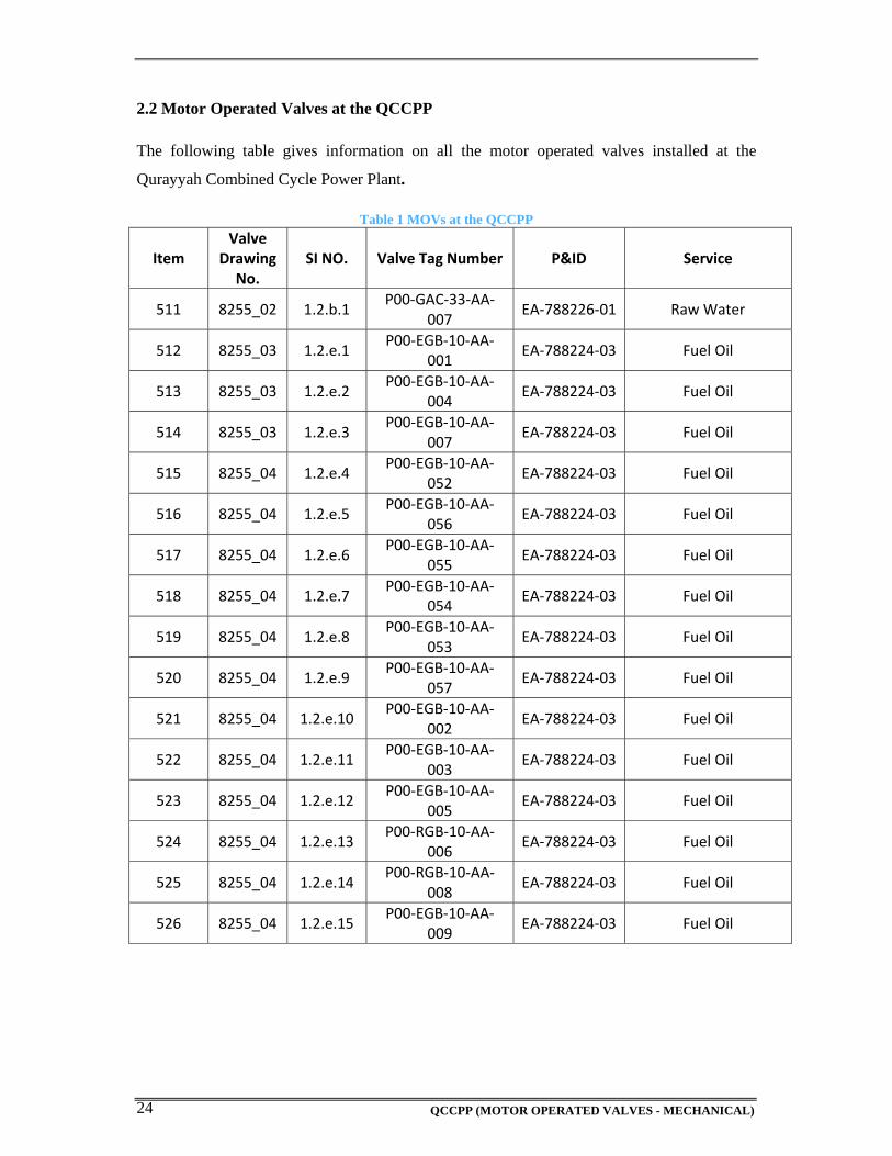
2.2 Motor Operated Valves at the QCCPP
The following table gives information on all the motor operated valves installed at the
Qurayyah Combined Cycle Power Plant.
Table 1 MOVs at the QCCPP
Item Valve
Drawing No.
SI NO. Valve Tag Number P&ID Service
511 8255_02 1.2.b.1 P00‐GAC‐33‐AA‐
007 EA‐788226‐01 Raw Water
512 8255_03 1.2.e.1 P00‐EGB‐10‐AA‐
001 EA‐788224‐03 Fuel Oil
513 8255_03 1.2.e.2 P00‐EGB‐10‐AA‐
004 EA‐788224‐03 Fuel Oil
514 8255_03 1.2.e.3 P00‐EGB‐10‐AA‐
007EA‐788224‐03 Fuel Oil
515 8255_04 1.2.e.4 P00‐EGB‐10‐AA‐
052 EA‐788224‐03 Fuel Oil
516 8255_04 1.2.e.5 P00‐EGB‐10‐AA‐
056 EA‐788224‐03 Fuel Oil
517 8255_04 1.2.e.6 P00‐EGB‐10‐AA‐
055 EA‐788224‐03 Fuel Oil
518 8255_04 1.2.e.7 P00‐EGB‐10‐AA‐
054 EA‐788224‐03 Fuel Oil
519 8255_04 1.2.e.8 P00‐EGB‐10‐AA‐
053EA‐788224‐03 Fuel Oil
520 8255_04 1.2.e.9 P00‐EGB‐10‐AA‐
057 EA‐788224‐03 Fuel Oil
521 8255_04 1.2.e.10 P00‐EGB‐10‐AA‐
002 EA‐788224‐03 Fuel Oil
522 8255_04 1.2.e.11 P00‐EGB‐10‐AA‐
003EA‐788224‐03 Fuel Oil
523 8255_04 1.2.e.12 P00‐EGB‐10‐AA‐
005 EA‐788224‐03 Fuel Oil
524 8255_04 1.2.e.13 P00‐RGB‐10‐AA‐
006 EA‐788224‐03 Fuel Oil
525 8255_04 1.2.e.14 P00‐RGB‐10‐AA‐
008 EA‐788224‐03 Fuel Oil
526 8255_04 1.2.e.15 P00‐EGB‐10‐AA‐
009 EA‐788224‐03 Fuel Oil
QCCPP (MOTOR OPERATED VALVES - MECHANICAL) 25
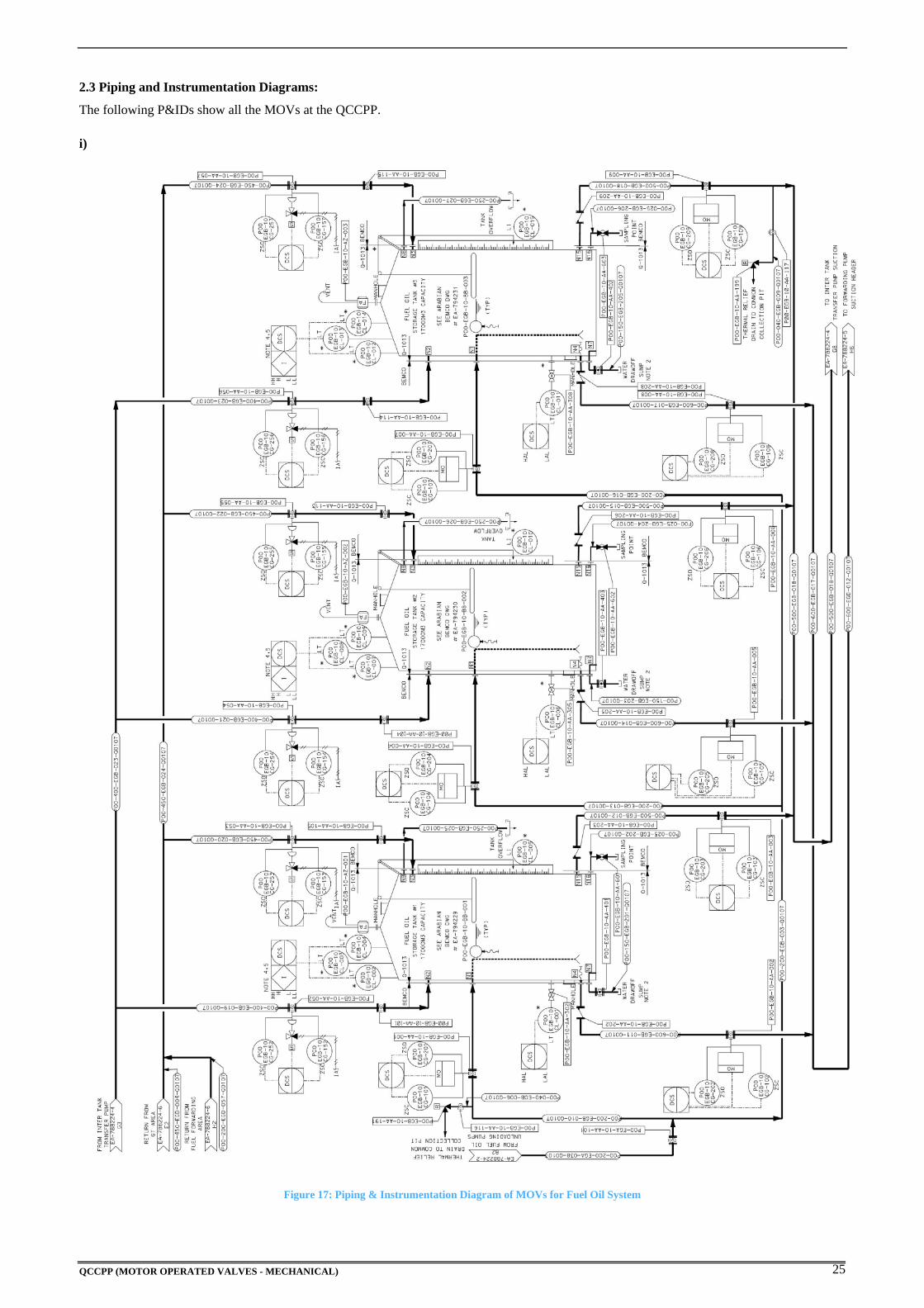
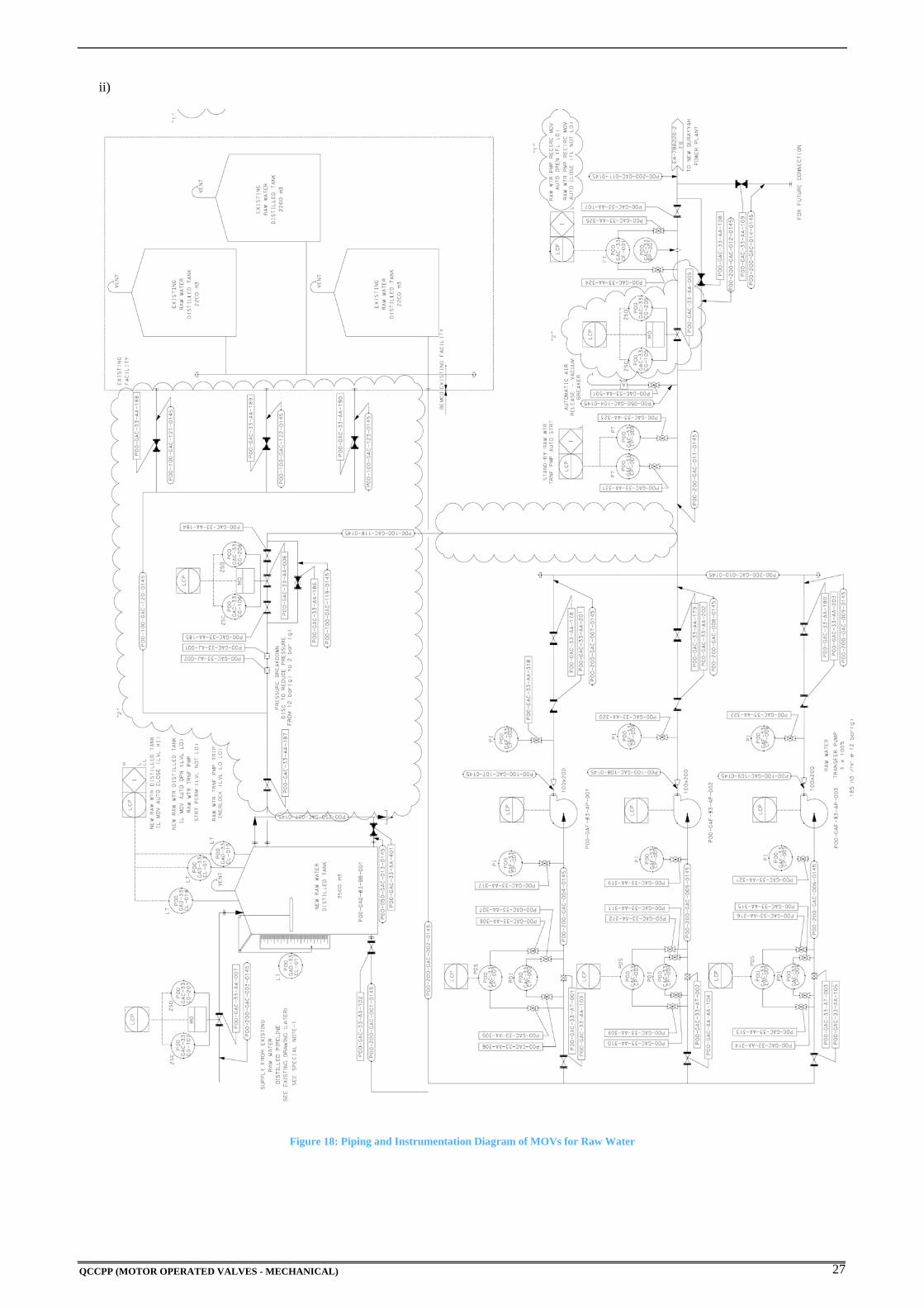
2.3 Piping and Instrumentation Diagrams:
The following P&IDs show all the MOVs at the QCCPP.
i)
Figure 17: Piping & Instrumentation Diagram of MOVs for Fuel Oil System

QCCPP (MOTOR OPERATED VALVES - MECHANICAL) 26
QCCPP (MOTOR OPERATED VALVES - MECHANICAL) 27
ii)
Figure 18: Piping and Instrumentation Diagram of MOVs for Raw Water

QCCPP (MOTOR OPERATED VALVES - MECHANICAL) 28
QCCPP (MOTOR OPERATED VALVES - MECHANICAL) 29
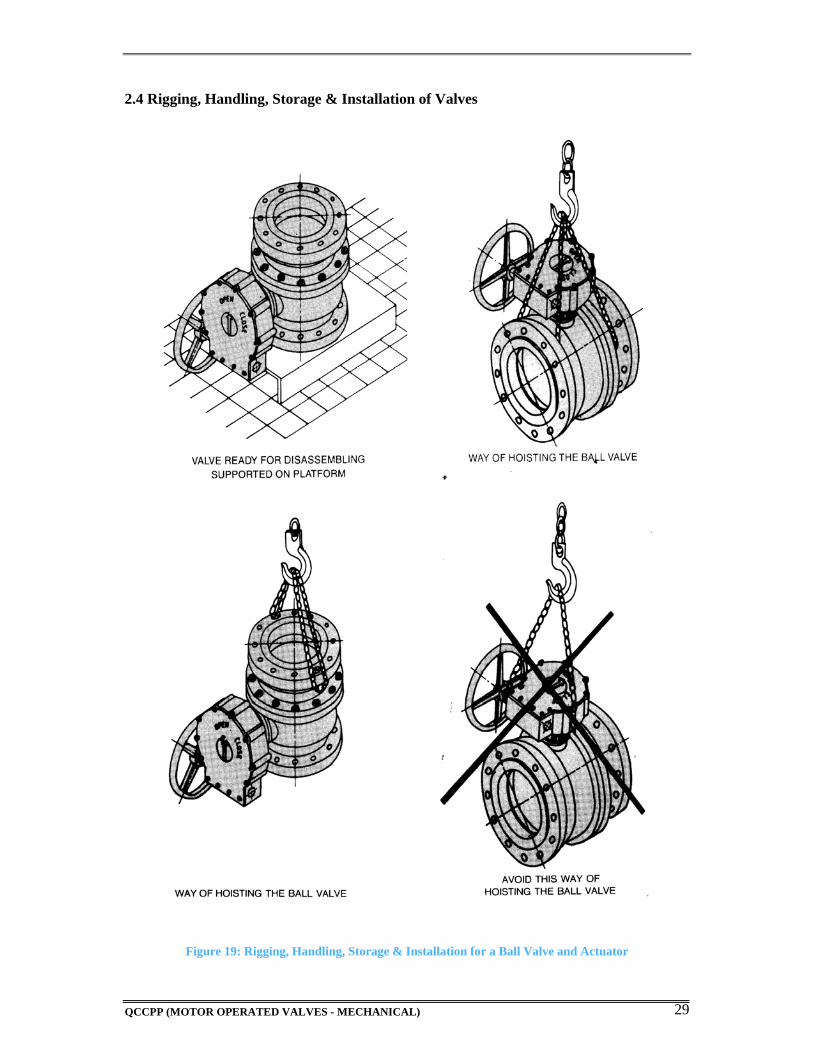
2.4 Rigging, Handling, Storage & Installation of Valves
Figure 19: Rigging, Handling, Storage & Installation for a Ball Valve and Actuator

QCCPP (MOTOR OPERATED VALVES - MECHANICAL) 30
QCCPP (MOTOR OPERATED VALVES - MECHANICAL) 31
CHAPTER 3
Valve Actuators

QCCPP (MOTOR OPERATED VALVES - MECHANICAL) 32
QCCPP (MOTOR OPERATED VALVES - MECHANICAL) 33
3.1 Valve Actuators
By themselves, valves cannot control a process. Manual valves require an operator to position
them to control a process variable. Valves that must be operated remotely and automatically
require special devices to move them. These devices are called actuators. Actuators may be
pneumatic, hydraulic, electric solenoids or motors. We will be dealing with motor actuators
in this manual. Following is a brief description on the function and components of motor
actuators.
Electric Motor Actuators
Electric motor actuators vary widely in their design and applications. Some electric motor
actuators are designed to operate in only two positions (fully open or fully closed). Other
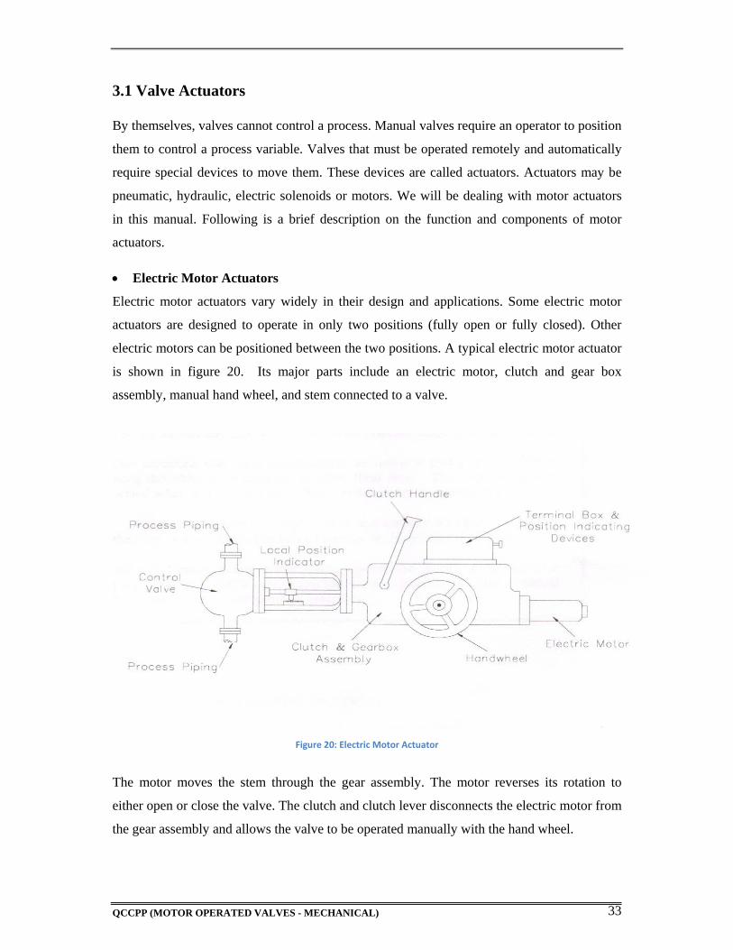
electric motors can be positioned between the two positions. A typical electric motor actuator
is shown in figure 20. Its major parts include an electric motor, clutch and gear box
assembly, manual hand wheel, and stem connected to a valve.
Figure 20: Electric Motor Actuator
The motor moves the stem through the gear assembly. The motor reverses its rotation to
either open or close the valve. The clutch and clutch lever disconnects the electric motor from
the gear assembly and allows the valve to be operated manually with the hand wheel.
QCCPP (MOTOR OPERATED VALVES - MECHANICAL) 34
Most electric motor actuators are equipped with limit switches, torque limiters, or both. Limit
switches de-energize the electric motor when the valve has reached a specific position.
Torque limiters de-energize the electric motor when the amount of turning force has reached
a specified value. The turning force normally is greatest when the valve reaches fully open or
fully closed position. This feature can also prevent damage to the actuator or valve if the
valve binds in an intermediate position.
QCCPP (MOTOR OPERATED VALVES - MECHANICAL) 35
3.2 Rotorik Actuator
3.2.1 Safety Precautions:
Prior to the commencement of actual work, the person carrying out the work is to make a
safety check based on the above method statement and also use his own judgment to ensure
that the equipment and the prevailing working conditions are safe. During maintenance work,
every employee should follow the safe working procedures detailed in the method statement.
Following is a list of points that need to be adhered to before commencing any maintenance
work.
Any personnel working with or on the equipment must be properly trained for the
work they are performing and be aware of their responsibilities relating to health and
safety in the workplace.
No inspection or repair should be undertaken unless it conforms to any applicable
hazardous area certification requirements. Under no circumstances should any
modification or alteration be carried out on the unit as this could invalidate the
certification.
3.2.2 Maintenance
Rotorik actuators are designed to work for long periods of time in the most severe conditions.
However, a preventative approach to maintenance helps prevent costly down time and can
actually reduce the cost of ownership. Preventive maintenance is carried out to avoid or
minimize the possibility of failure or deterioration of equipment performance. There are two
categories of preventive maintenance, routine maintenance and annual outage maintenance.
Though vendor/manufacturer’s recommendations provide a good basis for the provision of a
preventive maintenance schedule, the frequency and other details should be updated from
time to time based on the practical experience and actual feedback gathered through
inspection and normal operation of the equipment/plant.
Following is a list of points extracted from the manufacturer’s installation and operation
manual concerning the maintenance of ROTORIK actuators.
Ensure that the actuator correctly operates the valve within the required cycle time.
The actuator should be cycled several times with all the existing controls e.g., remote
QCCPP (MOTOR OPERATED VALVES - MECHANICAL) 36
control, local control and manual override; particularly if the actuator is not frequently
operated.
Verify that the power gas supply pressure value is within the required range.
Visually inspect external components of the actuator for physical damage.
Check pneumatic/hydraulic connections for leakage. Tighten pipe fittings as
required.
Remove dust and dirt build-up from all actuator surfaces. They can inhibit cooling
thus raising the temperature of the actuator above the maximum allowable limit.
Inspect actuator paint work for damaged to ensure continued corrosion protection.
Touch-up as required to applicable paint specification.
3.2.3 DISASSEMBLY AND REASSEMBLY
Disassembly and reassembly are the activities to be conducted when internal parts of the
equipment are required to be accessed. An important part of the activities is the preparatory
work. This should identify the manpower, spares and tools that may be required during the
maintenance work. A shortfall of any of these may affect the preset schedule and the
operational status of the plant. The major steps associated with disassembly and re-assembly
is as follows:
a) Prerequisites
If actuator disassembly becomes necessary, all associated equipment is to be mechanically
and electrically isolated and an authorized clearance and work permit shall be in place prior
to the commencement of work. The following points are also to be considered when
preparing for disassembly and reassembly:
Have all necessary drawings (assembly drawings, sectional drawings, part details,
etc.) and documents (log sheets, field record book, etc.) ready prior to start of
work. Ensure that the correct drawing is obtained for the actuator being worked
on. The unique drawing number for each actuator is given on the nameplate.
QCCPP (MOTOR OPERATED VALVES - MECHANICAL) 37
Prepare the necessary handling facilities and lifting equipment to remove and
store the various parts of the equipment.
Prior to carrying out any maintenance, confirm the equipment is shut down and all
isolations are in place.
b) Disassembly Procedure
1- Disconnect pneumatic and electrical supply connections. For spring return actuators,
ensure that the actuator is in the failed position (i.e., at end of the spring stroke).
2- Remove stop bolt nut (33).
3- Loosen stop nut (31) and remove stop bolt (32). 4- Remove tie rod nuts (34) from the tie rods (22). 5- Remove bottom flange (21). 6- Remove cylinder tube (19). 7- Remove housing cover bolts (16), center body cover (15) and cover gasket (14). 8- Remove piston retaining nut (35) and separate piston (23), shoulder washer (30), and o-
ring (36) from piston rod (20).
9- Remove o-ring (25) and sliding ring (24) from piston (23). 10- Remove piston rod (20) by unscrewing it from the guide block (4). 11- Remove flange retaining bolts (13) and remove head flange (18). 12- Remove head flange and bottom flange o-rings (26). 13- Remove bolts (38) and shaft seal retaining flange (37) from the head flange (18). 14- Remove o-ring (28) and shaft seal (29). 15- Clean all sealing surfaces. 16- Coat new o-rings, seals and gaskets with grease
QCCPP (MOTOR OPERATED VALVES - MECHANICAL) 38
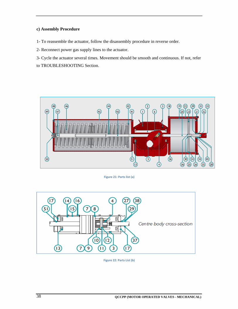
c) Assembly Procedure
1- To reassemble the actuator, follow the disassembly procedure in reverse order. 2- Reconnect power gas supply lines to the actuator. 3- Cycle the actuator several times. Movement should be smooth and continuous. If not, refer
to TROUBLESHOOTING Section.
Figure 21: Parts list (a)
Figure 22: Parts List (b)
QCCPP (MOTOR OPERATED VALVES - MECHANICAL) 39
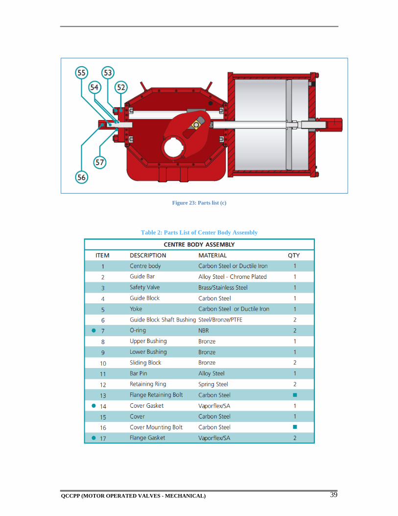
Figure 23: Parts list (c)
Table 2: Parts List of Center Body Assembly
QCCPP (MOTOR OPERATED VALVES - MECHANICAL) 40
QCCPP (MOTOR OPERATED VALVES - MECHANICAL) 41
QCCPP (MOTOR OPERATED VALVES - MECHANICAL) 42
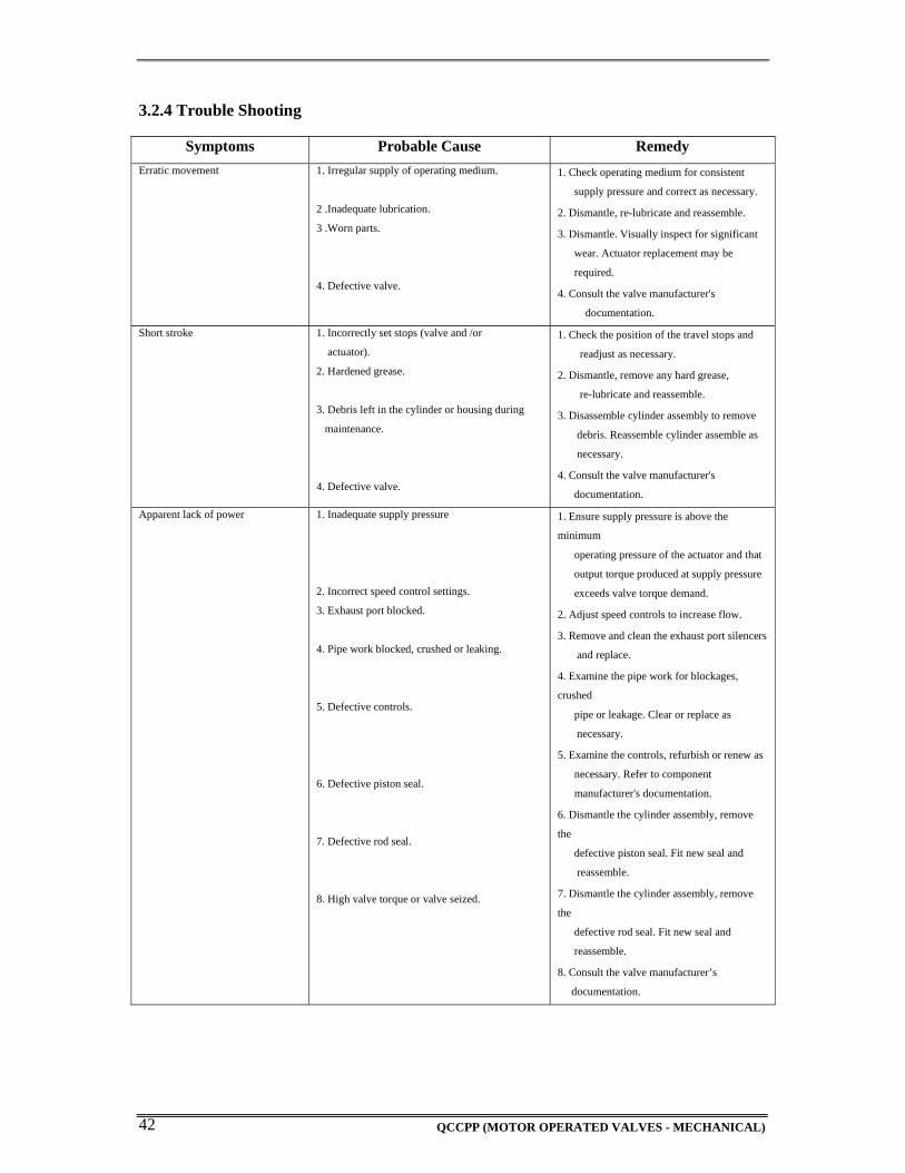
3.2.4 Trouble Shooting
Symptoms Probable Cause Remedy
Erratic movement 1. Irregular supply of operating medium.
2 .Inadequate lubrication.
3 .Worn parts.
4. Defective valve.
1. Check operating medium for consistent
supply pressure and correct as necessary.
2. Dismantle, re-lubricate and reassemble.
3. Dismantle. Visually inspect for significant
wear. Actuator replacement may be
required.
4. Consult the valve manufacturer's
documentation.
Short stroke 1. Incorrectly set stops (valve and /or
actuator).
2. Hardened grease.
3. Debris left in the cylinder or housing during
maintenance.
4. Defective valve.
1. Check the position of the travel stops and
readjust as necessary.
2. Dismantle, remove any hard grease,
re-lubricate and reassemble.
3. Disassemble cylinder assembly to remove
debris. Reassemble cylinder assemble as
necessary.
4. Consult the valve manufacturer's
documentation.
Apparent lack of power
1. Inadequate supply pressure
2. Incorrect speed control settings.
3. Exhaust port blocked.
4. Pipe work blocked, crushed or leaking.
5. Defective controls.
6. Defective piston seal.
7. Defective rod seal.
8. High valve torque or valve seized.
1. Ensure supply pressure is above the
minimum
operating pressure of the actuator and that
output torque produced at supply pressure
exceeds valve torque demand.
2. Adjust speed controls to increase flow.
3. Remove and clean the exhaust port silencers
and replace.
4. Examine the pipe work for blockages,
crushed
pipe or leakage. Clear or replace as
necessary.
5. Examine the controls, refurbish or renew as
necessary. Refer to component
manufacturer's documentation.
6. Dismantle the cylinder assembly, remove
the
defective piston seal. Fit new seal and
reassemble.
7. Dismantle the cylinder assembly, remove
the
defective rod seal. Fit new seal and
reassemble.
8. Consult the valve manufacturer’s
documentation.
QCCPP (MOTOR OPERATED VALVES - MECHANICAL) 43
3.3 LIMITORQUE ACTUATOR
3.3.1 Safety Precautions:
Prior to the commencement of actual work, the person carrying out the work is to make a
safety check based on the above method statement and also use his own judgment to ensure
that the equipment and the prevailing working conditions are safe. During maintenance work,
every employee should follow the safe working procedures detailed in the method statement.
Following is a list of points that need to be adhered to before commencing any maintenance
work.
Confirm the equipment is shut down and all isolations are in place
Disconnect all incoming power before opening limit switch compartment or working
on the torque switch.
Do not use an abrasive cloth to clean the contacts on the torque switch.
3.3.2 Maintenance
Under normal operating conditions, Limitorque MX actuator is a maintenance-free actuator.
For ordinary applications, the actuator will require no formal maintenance program.
However, if the actuator is used under severe service conditions or operated in a Hazardous
Location, the following maintenance procedures are required:
1. Check the oil level every 50 hours of operation at a minimum. Where conditions are severe
due to frequent operation or high ambient temperatures, a more regular inspection interval
should be maintained.
2. Change the gear oil every 100 hours of operation. (See Lubrication)
3. All ball bearings, oil seals, O-rings and quad-rings are to be replaced after 450 hours of
operation. Clean and lubricate the valve stem regularly to avoid torque build-up and wear due
to silting and corrosion. Infrequent operation can lead to corrosion and contamination of the
valve stem thread lubricant. Check any thrust bearings that are fitted to the actuator for proper
lubrication at regular intervals.
QCCPP (MOTOR OPERATED VALVES - MECHANICAL) 44
Lubrication
Limitorque MX actuators are oil-filled, as standard, using Mobil SHC 632. Exxon Teresstic
SHP 320 may be used as a direct substitute. These products are synthetic machine oils
suitable for ambient temperatures of -20°F to 250°F (30°C to 120°C). For extreme low
temperature conditions (< -30°C to -55°C), an alternative lubricant is available.
Oil Capacities
To avoid pressurization of the gear case, the following recommended oil capacities should
not be exceeded:
• MX-05 – 10 oz. (256 ml) MX-85 – 192 oz. (5.7 liters)
• MX-10 – 21 oz. (.6 liters) MX-140 – 192 oz. (5.7 liters)
• MX-20 – 48 oz. (1.4 liters) MX-150 – 192 oz. (5.7 liters)
• MX-40 – 65 oz. (1.9 liters)
Checking Oil Level
To check the level:
1. Remove the uppermost filler plug on the gear case.
2. Check that the level of oil is within 1 inch (25 mm) of the hole (when actuator is mounted
with base horizontal).
3.3.3 TROUBLESHOOTING
i) Actuator Fails to Operate
Actuator Fails to Operate from LOCAL Controls
1. Place the red selector knob in “LOCAL.”
2. If motor runs but actuator output does not turn, check that declutch lever has returned to
motor operation position.
3. Check LCD display for following alarms:
• If motor runs but no actuator movement is detected, check if the display says “JAMMED
VALVE” and free if necessary.
QCCPP (MOTOR OPERATED VALVES - MECHANICAL) 45
• Inhibit signal may be present or absent at the terminals. Check for signal and adjust as
necessary. “INHIBIT ACTIVE” appears on display.
• Thermal overload of the motor may have been detected. Check motor for high temperature.
Thermal overload is self-resetting when motor cools. “MOTOR OVERTEMP” appears on the
display.
4. Check to see if the position limits are set incorrectly on top of one another. See Section
3.5.4, Setting Position Limits.
5. Check to see if the reversing contact is plugged in correctly.
Actuator Fails to Operate from REMOTE Controls
1. Check that the actuator will operate from “LOCAL.” If not, then carry out the checks
described below.
2. Check that the red knob is in “REMOTE.”
3. ESD signal may be present or absent at the terminals. Check for signal and adjust as
necessary. (“ESD ACTIVE” at display.) If actuator previously operated in “LOCAL,” then
the fault is probably in the remote control circuit. Check the integrity of the cabling and that
the connections to the terminals are in accordance with the wiring diagram. If motor runs in
“LOCAL,” but not “REMOTE,” adjust ESD to be greater than local.
4. Confirm correct monitor relay operation.
ii) Jammed Valve Detected
1. Check that position limits have been set correctly. If valve is position-seated, the limits
should stop the motor just before the end-of-travel. Recalibrate the position limits if
necessary.
2. Check that torque settings are correct for the valve. Recalibrate if necessary.
3. Check the condition of the valve and lubrication of the valve stem and thrust bearings. The
valve may have remained in the same position for a long time and become corroded
internally or externally. Engage manual override and employ the hand wheel drive to unseat
the valve.
4. Verify that the actuator will now operate the valve. Open and close the valve a few times to
check for correct operation throughout the travel.
QCCPP (MOTOR OPERATED VALVES - MECHANICAL) 46
iii) Actuator Operates but Does Not Drive Valve
1. Verify that the ‘declutch lever’ has returned to motor-operated position.
2. Verify that the stem nut is fitted correctly in the actuator base.
3. Verify that the stem nut has sufficient engagement with the valve stem.
4. Verify that the key is fitted in bore/keyway applications.
iv) Valve Does Not Seat Correctly
1. Verify that position limits are calibrated correctly for the valve travel.
2. Verify that the torque-seating valves have been configured to close on torque, not position.
3. Verify that closing torque value has been set high enough to suit the process conditions.
4. Verify that the valve is not obstructed.
3.3.4 DISASSEMBLY AND REASSEMBLY
Disassembly and reassembly are the activities to be conducted when internal parts of the
equipment are required to be accessed. An important part of the activities is the preparatory
work. This should identify the manpower, spares and tools that may be required during the
maintenance work. A shortfall of any of these may affect the preset schedule and the
operational status of the plant. The major steps associated with disassembly and re-assembly
is as follows:
a) Prerequisites
If actuator disassembly becomes necessary, all associated equipment is to be mechanically
and electrically isolated and an authorized clearance and work permit shall be in place prior
to the commencement of work. The following points are also to be considered when
preparing for disassembly and reassembly:
Have all necessary drawings (assembly drawings, sectional drawings, part details,
etc.) and documents (log sheets, field record book, etc.) ready prior to start of
work. Ensure that the correct drawing is obtained for the actuator being worked
on. The unique drawing number for each actuator is given on the nameplate.
Prepare the necessary handling facilities and lifting equipment to remove and
store the various parts of the equipment.
QCCPP (MOTOR OPERATED VALVES - MECHANICAL) 47
Prior to carrying out any maintenance, confirm the equipment is shut down and all
isolations are in place.
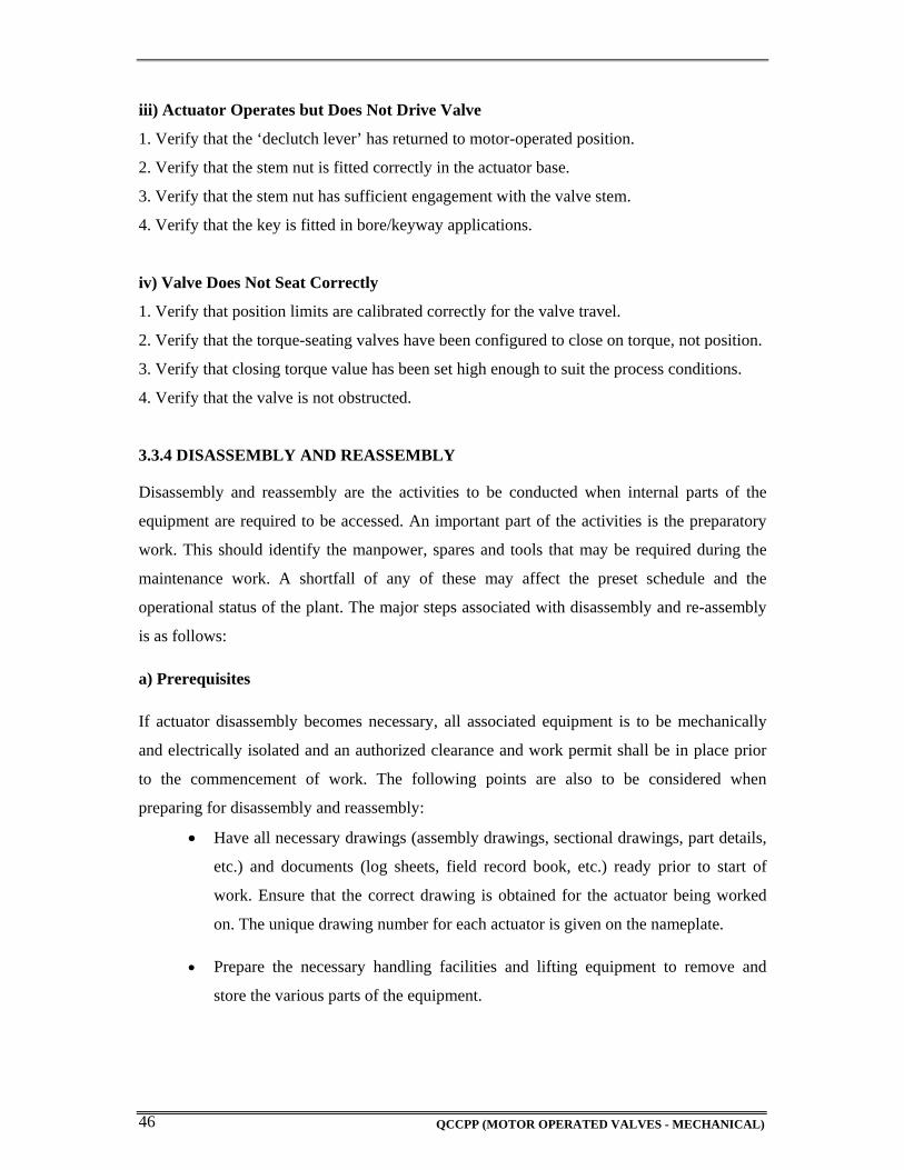
The standard MX actuator base is the B4 torque-only. It includes a mounting plate and steel
torque nut, which may be machined to fit a valve or gearbox. A B4E torque nut can be
provided and may be installed to allow for extended stem acceptance.
NOTE: Some MX actuators are supplied with single piece drive sleeves that have been
bored and keyed. These are typically mounted directly to gearboxes
Figure 24: MX actuator base
QCCPP (MOTOR OPERATED VALVES - MECHANICAL) 48
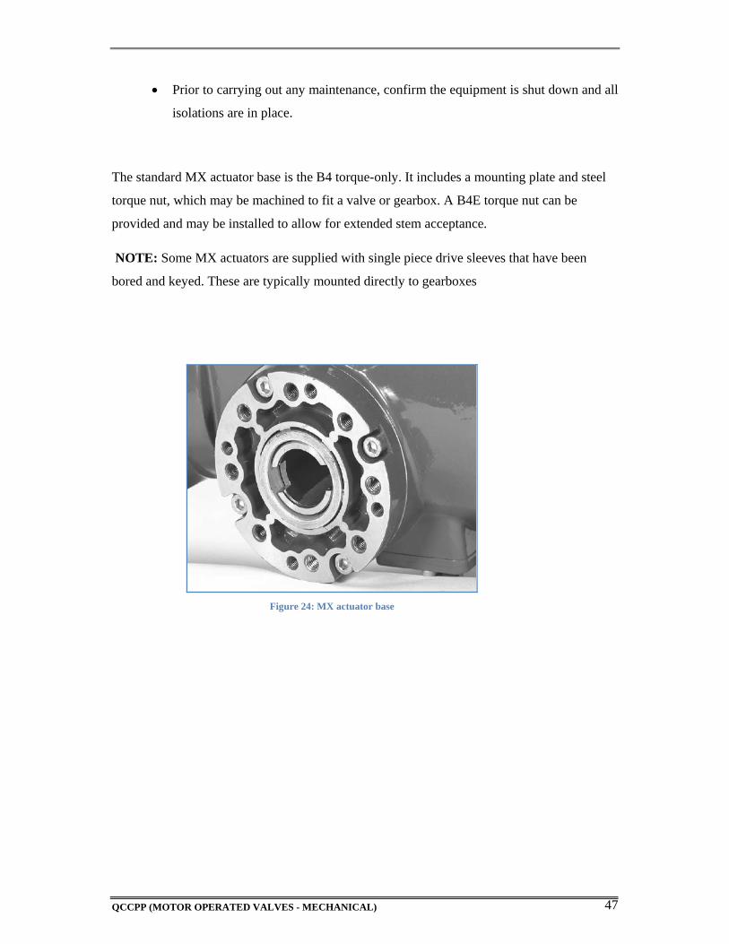
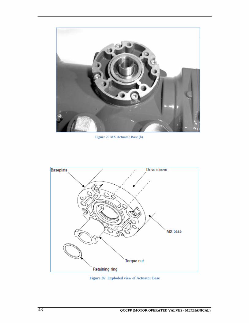
Figure 25 MX Actuator Base (b)
Figure 26: Exploded view of Actuator Base
QCCPP (MOTOR OPERATED VALVES - MECHANICAL) 49
b) Disassembly
1. Remove the retaining ring (B4 base) or spiral-wound ring (B4E base) that retains the torque nut in the drive sleeve.
2. Remove the torque nut. If the torque nut is difficult to remove, insert a suitable device into the drive sleeve through bore and gently tap it loose from the hand wheel end.
3. Machine the torque nut to suit the valve stem or gearbox input shaft. Ensure sufficient clearance for a smooth, sliding fit.
c) Reassembly
1. Clean the torque nut thoroughly and lightly grease.
2. Replace the torque nut in the drive sleeve. Ensure the torque nut meshes with the drive lugs.
3. Refit the retaining ring (B4 base) or spiral-wound ring (B4E base).
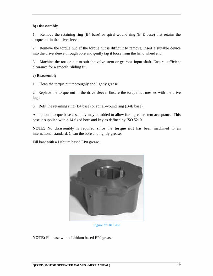
An optional torque base assembly may be added to allow for a greater stem acceptance. This base is supplied with a 14 fixed bore and key as defined by ISO 5210.
NOTE: No disassembly is required since the torque nut has been machined to an international standard. Clean the bore and lightly grease.
Fill base with a Lithium based EP0 grease.
Figure 27: B1 Base
NOTE: Fill base with a Lithium based EP0 grease.
QCCPP (MOTOR OPERATED VALVES - MECHANICAL) 50
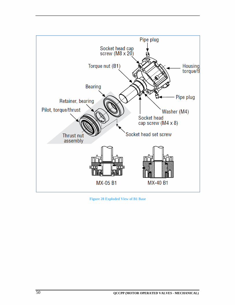
Figure 28 Exploded View of B1 Base
QCCPP (MOTOR OPERATED VALVES - MECHANICAL) 51
3.4 EIM Actuators 3.4.1 Safety Precautions:
Prior to the commencement of actual work, the person carrying out the work is to make a
safety check based on the above method statement and also use his own judgment to ensure
that the equipment and the prevailing working conditions are safe. During maintenance work,
every employee should follow the safe working procedures detailed in the method statement.
Following is a list of points that need to be adhered to before commencing any maintenance
work.
Confirm the equipment is shut down and all isolations are in place
Disconnect all incoming power before opening limit switch compartment or working
on the torque switch.
Do not use an abrasive cloth to clean the contacts on the torque switch. 3.4.2 MAINTENANCE
At least once a year a check should be made of your EIM actuator.
a) Disconnect all electrical power to actuator.
b) Open Electrical Enclosure. Inspect and tighten all electrical connections.
c) Visually inspect for any electrical or mechanical damage. Replace worn or damaged
components
d) Check lubrication consistency and level. Fill or replace if required.
3.4.3 LUBRICATION
ElM Actuators are factory filled with a high quality lubricant carefully selected to insure
actuator performance under specified operating conditions. Normal operation of actuator will
not require replacement of lubricant.
QCCPP (MOTOR OPERATED VALVES - MECHANICAL) 52
3.4.4 DISASSEMBLY AND REASSEMBLY
Disassembly and reassembly are the activities to be conducted when internal parts of the
equipment are required to be accessed. An important part of the activities is the preparatory
work. This should identify the manpower, spares and tools that may be required during the
maintenance work. A shortfall of any of these may affect the preset schedule and the
operational status of the plant. The major steps associated with disassembly and re-assembly
is as follows:
a) Prerequisites
If actuator disassembly becomes necessary, all associated equipment is to be mechanically
and electrically isolated and an authorized clearance and work permit shall be in place prior
to the commencement of work. The following points are also to be considered when
preparing for disassembly and reassembly:
Have all necessary drawings (assembly drawings, sectional drawings, part details,
etc.) and documents (log sheets, field record book, etc.) ready prior to start of
work. Ensure that the correct drawing is obtained for the actuator being worked
on. The unique drawing number for each actuator is given on the nameplate.
Prepare the necessary handling facilities and lifting equipment to remove and
store the various parts of the equipment.
Prior to carrying out any maintenance, confirm the equipment is shut down and all
isolations are in place.
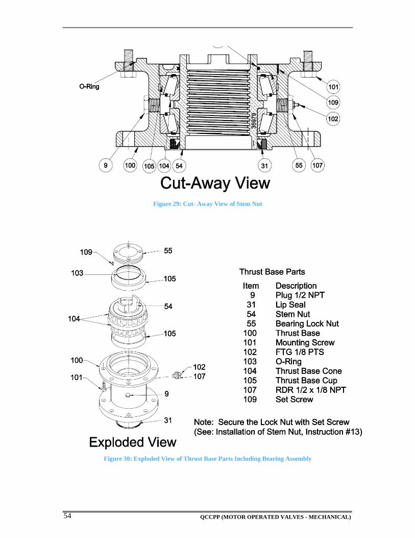
b) REMOVAL OF STEM NUT FROM THRUST SPOOL
Use Exploded View in figure 31 for reference.
1) Locate Thrust Mounting Bolts (Item 101).
2) Remove the eight mounting bolts and separate the spool (Item 100) from the unit.
3) Remove Set Screw from Lock Nut (Item 55).
4) Remove Lock Nut (Item 55) from spool (Item 100).
5) Remove Bearing Cup (Item 105).
6) Remove Stem Nut (Item 54) from Spool (Bearings will be attached).
QCCPP (MOTOR OPERATED VALVES - MECHANICAL) 53
c) REMOVAL OF BEARINGS FROM STEM NUT
7) Use a Draft and a Ball Pen Hammer to tap the bearings off the Stem Nut (Item 54).
CAUTION: Be careful not to mar up the seal area on the stem nut when removing bearings.
Marring will cause leakage of lubricant and void the EIM Warranty.
8) The Stem Nut is now ready for tapping.
d) INSTALLATION OF STEM NUT
9) Place the Stem Nut and Bearings back into the spool.
CAUTION: When installing the Stem Nut, be careful of Lip Seal on Bottom Side
(Use a flat screwdriver to shape the seal around the Stem Nut).
10) Using grease fitting (Item 102), lubricate the cavity in the spool; rotate the Stem Nut
(item 54) so that an adequate amount of lubrication is spread to cover the bearings (Item
104).
11) Re-install Bearing Cap (Item 105) onto the spool.
12) Re-install the Lock Nut (Item 55).
CAUTION: Be careful not to cut the O-Ring inside the Lock Nut.
13) Secure the Lock Nut (Item 55) to original position so that the Set Screw can be
reinstalled.
NOTE: If Set Screw was never installed perform the following:
Drill Set Screw after securing Lock Nut (Item 55), Center punch between Spool and
Lock Nut. Use a Letter “I” drill bit and go ½” deep, tap with a 5/16-24. Install Set Screw
(109).
14) Re-install the Set Screw. (Use Locktite Sealant)
15) Refer to installation of the Thrust Spool with Threaded Stem Nut for remainder of the
installation procedure.
QCCPP (MOTOR OPERATED VALVES - MECHANICAL) 54
Figure 29: Cut- Away View of Stem Nut
Figure 30: Exploded View of Thrust Base Parts Including Bearing Assembly
QCCPP (MOTOR OPERATED VALVES - MECHANICAL) 55
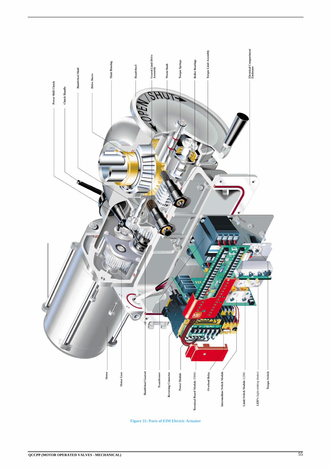
Figure 31: Parts of EIM Electric Actuator

QCCPP (MOTOR OPERATED VALVES - MECHANICAL) 56
QCCPP (MOTOR OPERATED VALVES - MECHANICAL) 57
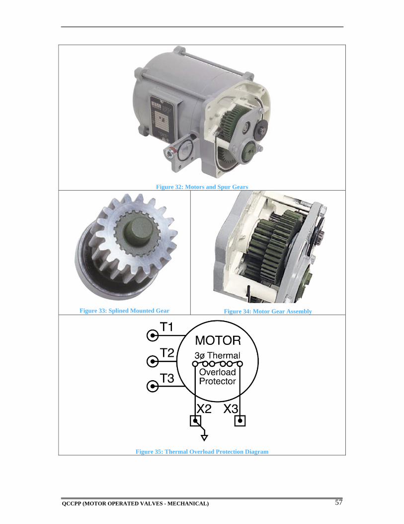
Figure 32: Motors and Spur Gears
Figure 33: Splined Mounted Gear
Figure 34: Motor Gear Assembly
Figure 35: Thermal Overload Protection Diagram
QCCPP (MOTOR OPERATED VALVES - MECHANICAL) 58
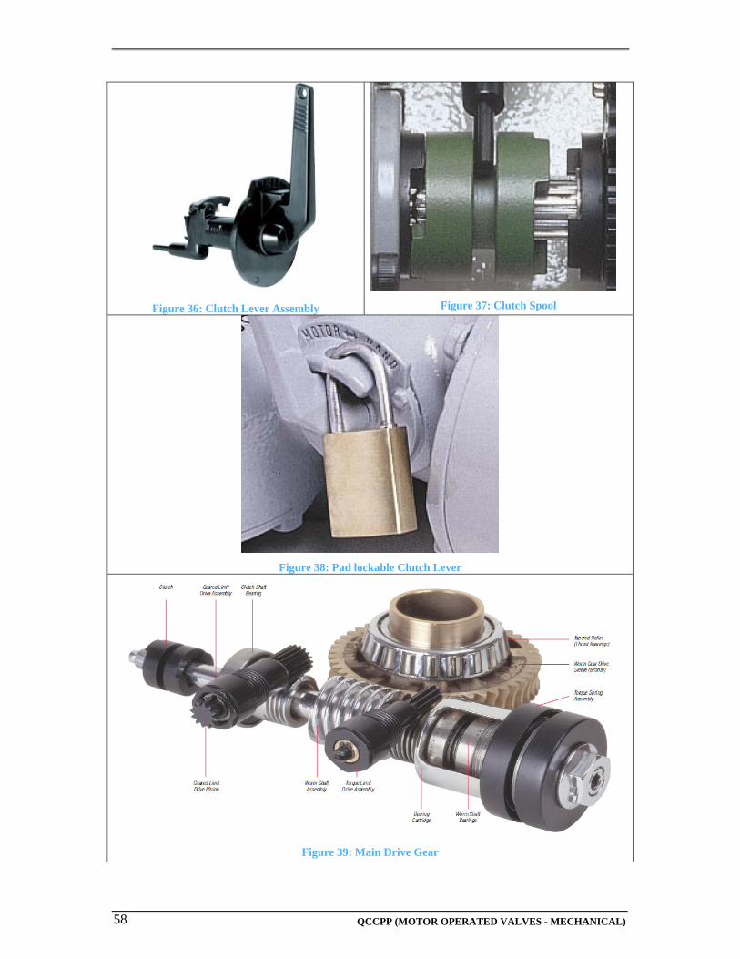
Figure 36: Clutch Lever Assembly
Figure 37: Clutch Spool
Figure 38: Pad lockable Clutch Lever
Figure 39: Main Drive Gear
QCCPP (MOTOR OPERATED VALVES - MECHANICAL) 59
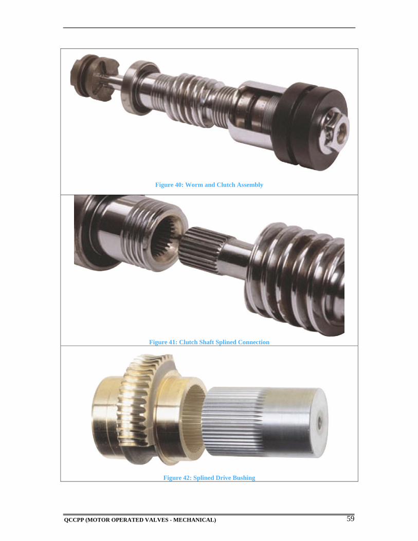
Figure 40: Worm and Clutch Assembly
Figure 41: Clutch Shaft Splined Connection
Figure 42: Splined Drive Bushing
QCCPP (MOTOR OPERATED VALVES - MECHANICAL) 60
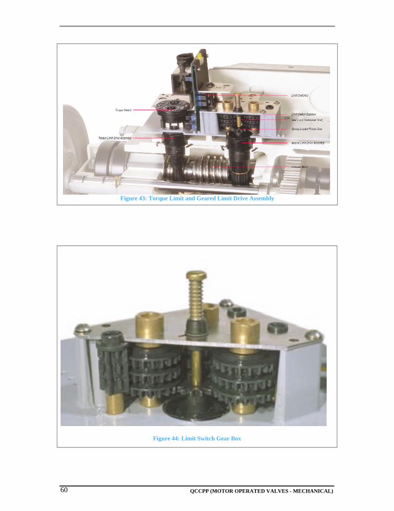
Figure 44: Limit Switch Gear Box
Figure 43: Torque Limit and Geared Limit Drive Assembly
QCCPP (MOTOR OPERATED VALVES - MECHANICAL) 61
CHAPTER 4
TASKSHEETS

QCCPP (MOTOR OPERATED VALVES - MECHANICAL) 62
QCCPP (MOTOR OPERATED VALVES - MECHANICAL) 63
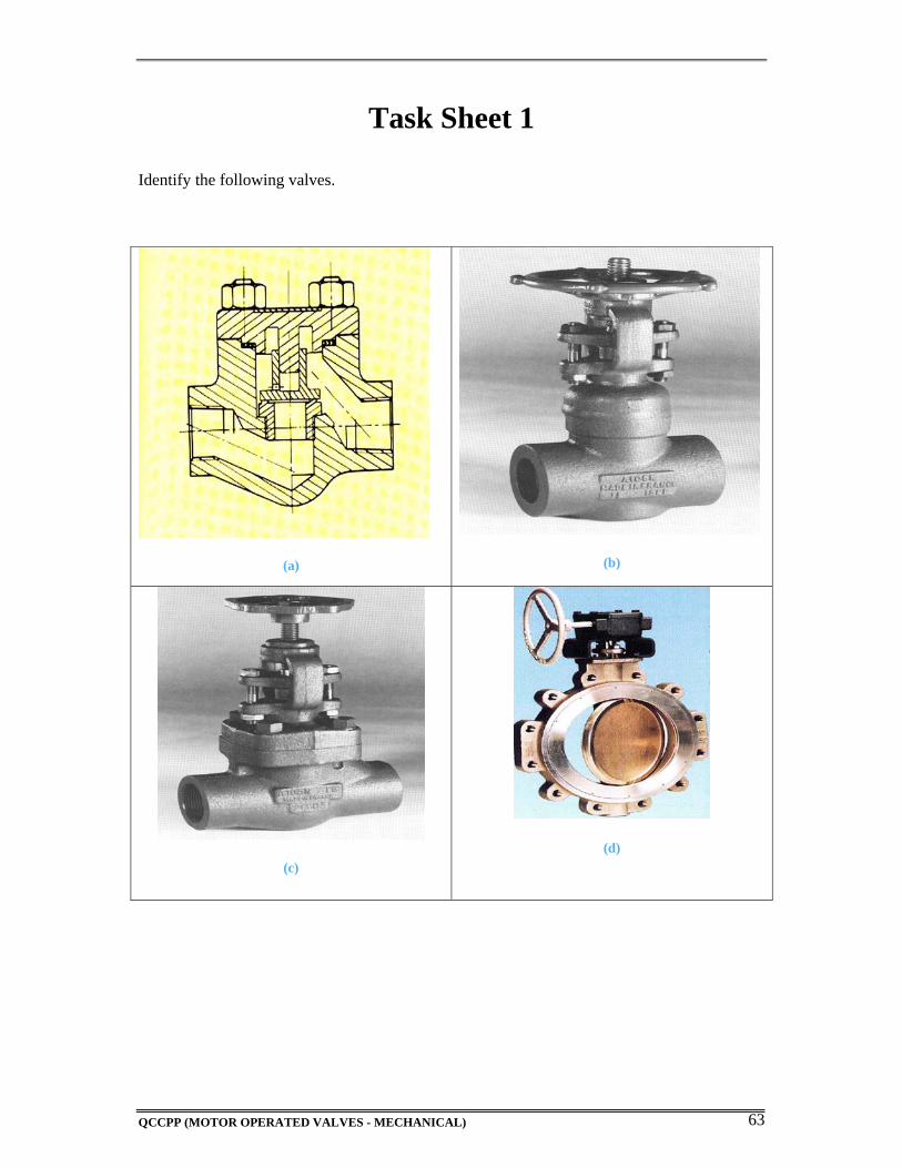
Task Sheet 1
Identify the following valves.
(a)
(b)
(c)
(d)

QCCPP (MOTOR OPERATED VALVES - MECHANICAL) 64
QCCPP (MOTOR OPERATED VALVES - MECHANICAL) 65
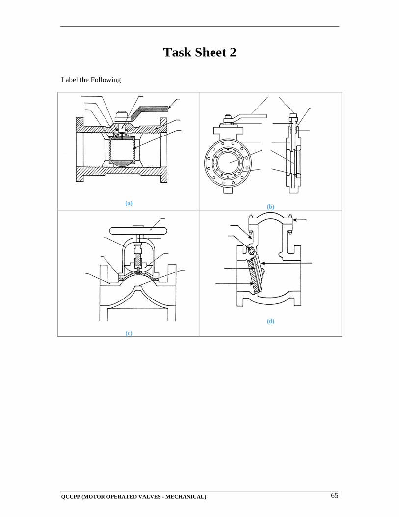
Task Sheet 2
Label the Following
(a)
(b)
(c)
(d)

QCCPP (MOTOR OPERATED VALVES - MECHANICAL) 66
QCCPP (MOTOR OPERATED VALVES - MECHANICAL) 67
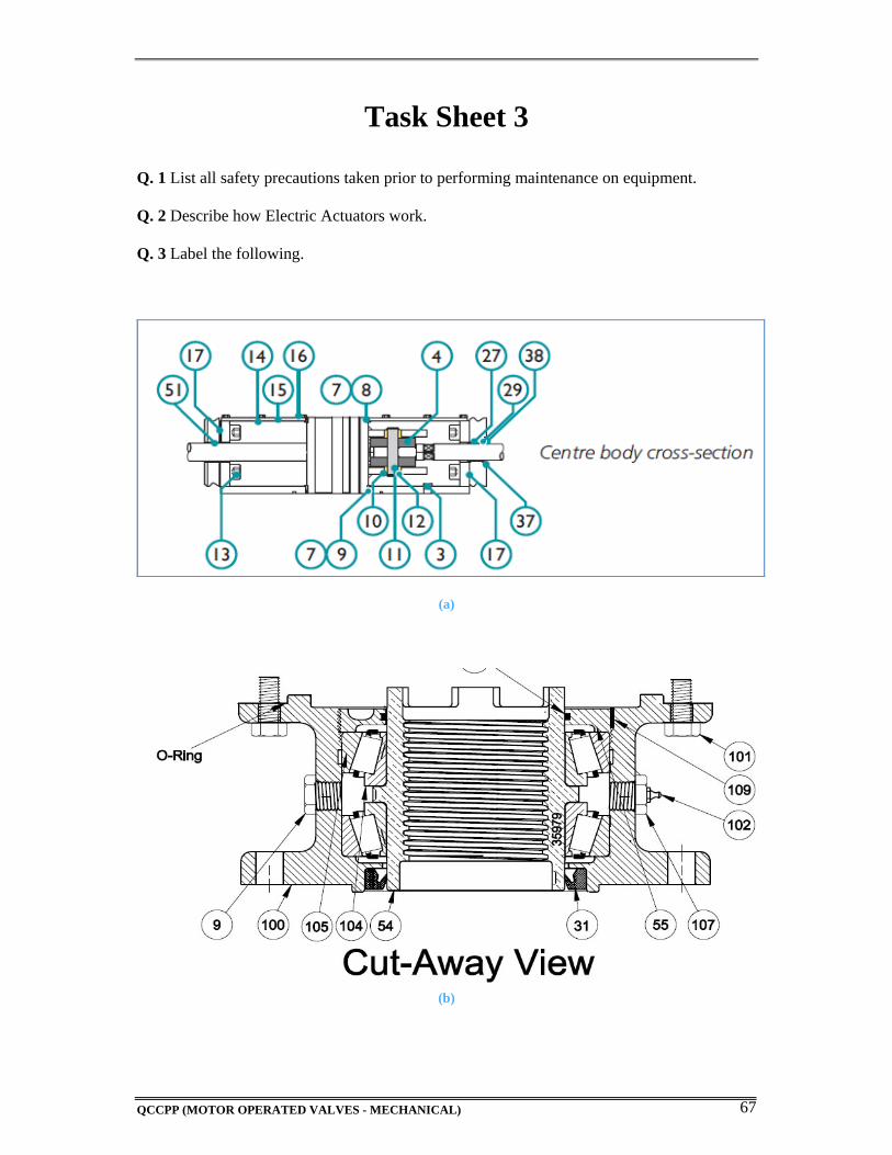
Task Sheet 3
Q. 1 List all safety precautions taken prior to performing maintenance on equipment.
Q. 2 Describe how Electric Actuators work.
Q. 3 Label the following.
(a)
(b)

QCCPP (MOTOR OPERATED VALVES - MECHANICAL) 68