moss-europe.co · place hydraulic jack (preferably trolley type) ... the damper is fitted with an...
TRANSCRIPT
Dynamic Coil-Over Suspension Fitting Instructions
Part Numbers: TMG40750G/TMG40751G/TMG40752GDescription: Dynamic Coil-Over SuspensionApplications: MGBTools Required: As normal for work on the front suspension (see workshop manual), plus:
• WD-40 (or similar releasing fluid spray).• Copaslip grease (or similar).• An electric drill.• A sharp, coarse 1/2 round file.
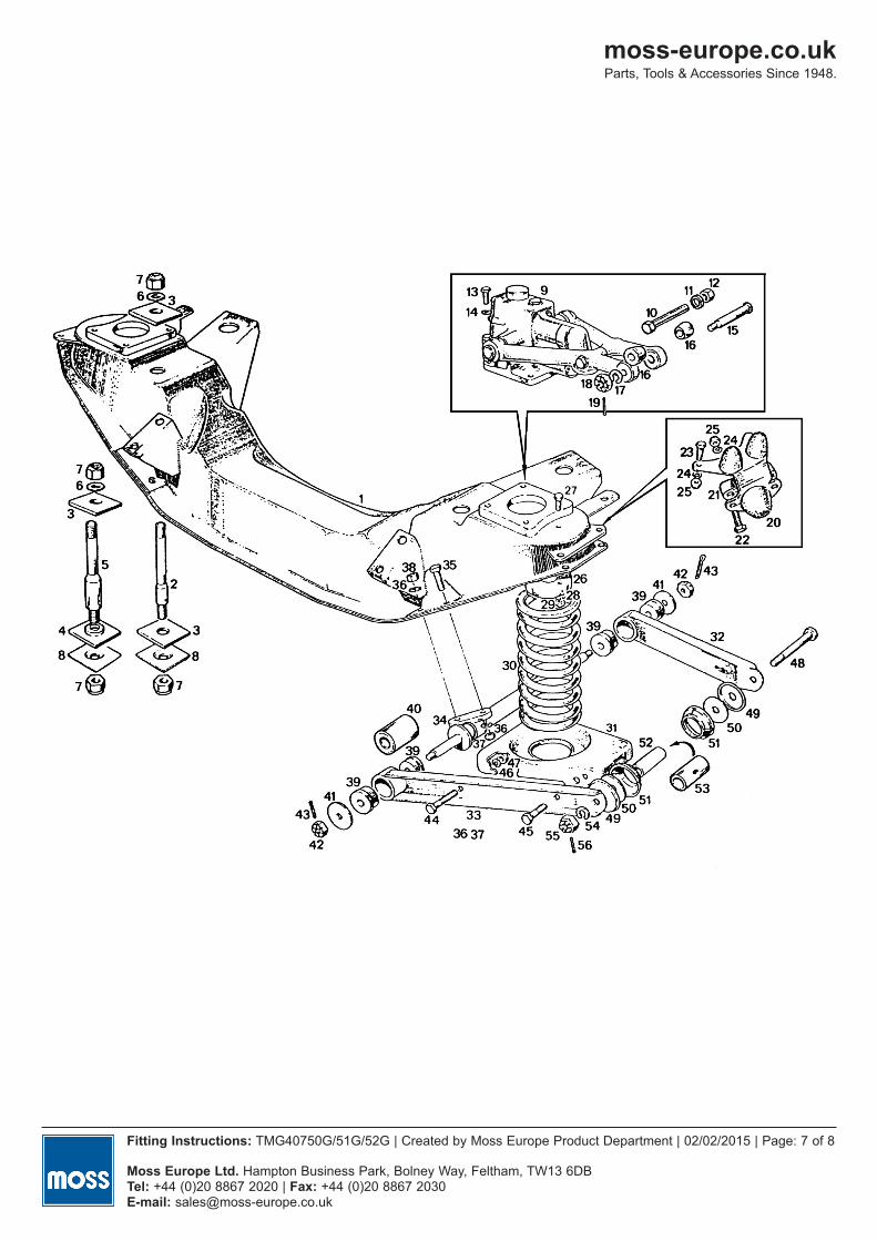
PreparationIt is recommended to read through these instructions carefully before commencing any work. The numbers referred to inbrackets ( ) is a reference to the attached drawing.
1. All nuts and bolts to be undone should be soaked in releasing fluid, preferably 24hrs before work starts.2. Park car on a level surface. Check and note the height from centre of front wheel arch to centre of hub on both
front wheels. It should be approx 38cms (15”) for rubber bumper models. Chock behind rear wheels. Applyhandbrake. Loosen front wheel nuts. Jack up and support bodywork at a suitable height for working under car.Remove front wheels.
3. Remove the brake caliper by levering back the ears of the lockwasher and remove the 2x securing bolts. Supportor tie up caliper out of the way to the inner wheel arch with wire to avoid weight being taken by hydraulic hose.Retain bolts and washers for later use in assembly or replace if unusable. (Refer to manual if in doubt).
4. Remove the anti roll bar bolts and retain for later fitment.5. Place hydraulic jack (preferably trolley type) under spring pan (31) with a piece of wood between jack head and
pan and raise the jack to partially compress the coil spring. With the weight partially removed, the nuts and bolts(44,45,46,47) retaining the spring pan to lower wishbone arms (32,33) can be removed. Also remove the anti rollbar drop link from the wishbone/spring pan assembly. With the use of the jack, the spring pan can now be loweredfor the safe removal of the road spring (30).
6. Undo the steering arm bolts and retain.7. Undo the upper (15) and lower (48) kingpin fulcrum/pivot bolts by removing the split pins (19 & 56) from the
castellated nuts (18 & 55) and undoing the nuts. Remove the upper fulcrum pin (15) by carefully knocking it outand discard. The kingpin assembly can now be allowed to rotate outwards under control.
8. Carefully knock out lower kingpin bolt (48) and retain if reusable. Remove the whole kingpin/brake disc assemblyand put aside. Retain the standard sleeve/distance tube (52) and end seal assemblies (49,50,51) if in a reusablestate. If any of these parts are not reusable, replacements can be obtained from your Moss dealer. Please refer toyour Moss catalogue for part numbers.
9. Clean up lower wishbone arms with a wire brush and rag. Check outer kingpin bolt holes in lower wishbone arms(32,33) for wear, ovality or elongation. Please discard and replace if found to be worn. Please refer to Mosscatalogue for part numbers.
10. Undo 4 bolts and spring washers (13,14) and remove lever arm damper (9). Retain 2 bolts and discard the othersand the damper.
11. Remove upper spring locator/spigot (26) on underside of crossmember by undoing and removing 2 nuts and bolts(27) and discard.
12. Remove the rebound buffer. (20)13. Repeat steps 3-12 for the other side of the car.
moss-europe.co.ukParts, Tools & Accessories Since 1948.
Fitting Instructions: TMG40750G/51G/52G | Created by Moss Europe Product Department | 02/02/2015 | Page: 1 of 8
Moss Europe Ltd. Hampton Business Park, Bolney Way, Feltham, TW13 6DBTel: +44 (0)20 8867 2020 | Fax: +44 (0)20 8867 2030 E-mail: [email protected]

Getting Started1. Offer up the drill template to the underside of the crossmember. Check that it is aligned with the recessed hole in
the upper side of the crossmember and that the cut out notch is facing away from the engine and that the holes inthe plate line up with the existing damper securing bolt holes. Secure using the 2x damper bolts retained (13) intothe lever arm damper securing bolt holes from below.
2. Wearing suitable eye and breathing protection, use the smaller of the drill bits (1/8”) supplied in the kit to drillthrough the template to produce a ring of holes. Use a slow speed setting and oil to keep the drill bit cool in orderto keep an edge on the drill bit. Remove the template.
3. Change to the larger drill bit (1/4”) supplied and repeat the circle of drilling, again using a slow speed. Oncecomplete, remove the jagged centre piece using a hammer and cold chisel. Finish opening the hole with a sharpcoarse half round file. The finished hole should be circular and large enough to allow the upper damper loop (whichhas the bushes already fitted) to pass through. (Installation can be made easier by either allowing the hole to havefour grooves in order for the bush in the upper damper loop to pass through, or alternatively, the bush can beremoved from the upper damper loop by removing the metal sleeve from the bush, the 2x halves of the bush canthen be removed thus reducing the size of the upper damper loop. Reassemble in situ). Please use a suitablecoating on the exposed cut metal to prevent corrosion.
4. Repeat steps 1-3 on the other side of the car.5. Identify L/H and R/H upper wishbone arms. The arms come in pairs. One of the pair has a threaded block and the
other arm is plain. The upper kingpin/trunnion bolt fits from the front, through the plain arm and into the threadedarm behind. Do not mix up arms.
6. Install polyurethane bushes supplied (BHH1123SP) into the wishbone arms. Please follow the manufacturer’sinstructions regarding the fitting of these bushes. These are located within the packaging of the bush.
7. Identify the pairs of upper support blocks (TMG49082). These are in pairs marked L and R and must be used aspairs as the holes are offset to match the hole pattern in the lever arm damper. These blocks will be mounted inplace of the dampers during assembly.
8. Assemble damper and road spring. First, screw the bottom spring retaining ring on the damper down as far it will go.Then extend the telescopic portion of the damper to full height. Pull down the rubber bung on the telescopic portionenough to remove the top spring retaining plate. Remove the plate and place road spring over the damper.Reassemble the top spring plate onto the damper and screw up the bottom spring retaining ring. The use of the Cspanner provided in the kit will he be required. Final adjustment of the spring will be done when the assembly is complete.
9. The damper is fitted with an inbuilt rebound stop that is adjusted by use of a knob on the lower side of the damper. As a basis for set up purposes, we recommend that this knob is turned 20 clicks to the right. The final position forthis setting will be done when assembly is complete.
10. Remove the existing rubber bushes from the top trunnion of the stub axle.11. Install polyurethane bushes supplied (8G621SP) into top trunnion. Please follow the manufacturer’s
instructions regarding the fitting of these bushes. These are located within the packaging of the bush.
AssemblyUse Copaslip on all metal to metal contact points such as bushes and pin/post apertures.
Top Assembly1. Locate the 4x grub screws into the 4x support posts and turn them enough to get them started in the threads. This
will ease location later on.
moss-europe.co.ukParts, Tools & Accessories Since 1948.
Fitting Instructions: TMG40750G/51G/52G | Created by Moss Europe Product Department | 02/02/2015 | Page: 2 of 8
Moss Europe Ltd. Hampton Business Park, Bolney Way, Feltham, TW13 6DBTel: +44 (0)20 8867 2020 | Fax: +44 (0)20 8867 2030 E-mail: [email protected]

2. Fit the upper support posts and top plate on top of the crossmember to the former lever arm damper holes using4x bolts (BHH606261) and lock washers supplied. Use lock and seal on the threads. Finger tight only at this stage.Make sure that the post marked L is on the left and the post marked R is on the right (as you look at it).
3. Position the upper loop of the damper assembly through the hole in the crossmember and between the supportposts. Insert the top spindle (TMG49102) with the 2x flat surfaces uppermost, through the hole in the support post,through the upper loop in the damper assembly and through the hole in the other support post. Make sure the topspindle is equidistant on both sides. Using the hex key, tighten the grub screws enough to hold the spindle firm.The wishbone arms and damper should pivot around the spindle. Do not tighten fully at this stage.
4. Fit wishbone arms to either side on the spindle. Make sure that the front and rear are correct (refer to section 5 onpage 2. Getting Started). Secure with a large plain washer at either end and thin M12 (NZ112041) Nyloc nut eitherend. Finger tight only at this stage.
Lower Assembly5. Fit new lower spring pan (damper fixing point underneath) to existing lower wishbone arms using 3x of the small
bolts, plain washers and locknuts, supplied in the kit. Leave all loose at this stage.6. Install the lower damper bolt (BH114201) and lock nut from the front, through the damper fixing point in the spring
pan and through the lower loop of the damper. Leave loose at this stage.7. Connect the anti roll bar link to lower wishbone in 4th hole in the spring pan, from the outside. Leave loose at this stage.8. Refit the lower kingpin assembly to the lower wishbone arms using the old lower kingpin (48) with standard sleeve
(52) and end seal assemblies (49,50 & 51). Put on securing nut (55). Do not tighten at this stage. (If any of thehardware is not reusable, please replace).
9. Tighten up spring pan nuts (torque setting 22lbs/ft, 30Nm) and the lower anti roll bar link nut. (The latter will requirethe use of an open jawed spanner).
Torque settings are given only when available from the workshop manual. All other nuts/bolts should be tightenedoff sufficiently for security. Do not over tighten.
Final Assembly 10. Reconnect the steering arm/lever (19) and tighten the bolts (torque setting 60-65lbs/ft, 81- 88Nm).11. Rotate the kingpin assembly up and position between the upper wishbone arms. Install new upper fulcrum/pivot
bolt and washer from the front, through wishbone arm and top trunnion and finger tighten into threaded boss in therear wishbone arm. When tightened up, use the 1/2 UNF thin nut as a lock nut on the bolt threads. The use of ahydraulic jack will probably be required to lift the new lower spring pan by a small amount to allow the bolt/washerto be inserted.
12. With the jack still in place, fit the central distance piece between the upper wishbone arms and secure using nuts,bolts and washers supplied.
13. Release the jack carefully.14. Tighten up all nuts and bolts;
A. Upper outer kingpin pivot/fulcrum bolt. Use the plain nut supplied as a lock nut. B. Lower kingpin pivot/fulcrum bolt. Tighten up and fit new split pin.C. Anti roll bar link nut, using an open ended spanner.D. Check spring pan bolts (torque setting 22lbs/ft, 30Nm).E. Bottom damper bolt.
moss-europe.co.ukParts, Tools & Accessories Since 1948.
Fitting Instructions: TMG40750G/51G/52G | Created by Moss Europe Product Department | 02/02/2015 | Page: 3 of 8
Moss Europe Ltd. Hampton Business Park, Bolney Way, Feltham, TW13 6DBTel: +44 (0)20 8867 2020 | Fax: +44 (0)20 8867 2030 E-mail: [email protected]

moss-europe.co.ukParts, Tools & Accessories Since 1948.
Fitting Instructions: TMG40750G/51G/52G | Created by Moss Europe Product Department | 02/02/2015 | Page: 4 of 8
Moss Europe Ltd. Hampton Business Park, Bolney Way, Feltham, TW13 6DBTel: +44 (0)20 8867 2020 | Fax: +44 (0)20 8867 2030 E-mail: [email protected]
F. Upper support post bolts (torque setting 43-45lbs/ft, 58-61Nm).G. Grub screws. They should hold the spindle static. The wishbone arms and damper should pivot freely.H. Upper pivot/fulcrum pin (spindle) lock nuts.I. Upper wishbone central distance piece bolt.
Repeat steps 1 to 14 for the other side of the car.
Now check all the nuts again.
15. Replace brake caliper and tighten securing nuts over a new lock washer (torque setting 40-45lbs/ft, 54-61Nm).16. Refit the roll bar upper link bolts and tighten up.17. Pump grease into 2x lower kingpin grease nipples on each side (refer to workshop manual).18. Replace road wheels, finger tighten the securing bolts, then lower the car and tighten the road wheel nuts. (torque
setting 60-65lbs/ft, 81-88Nm)19. Check the ride height of the car. The height from top centre of wheel arch to centre of hub should now be 36cm.
If higher, check again after initial shake-down drive and use C spanner to adjust damper/spring rings if required.Check toe-in (refer to workshop manual).
20. Test drive the car. Then adjust the damper settings, ride height and toe-in again, if required.21. To adjust the rate of the damper, the knob on the damper can be rotated clockwise to increase the damper setting or anti
clockwise to decrease the setting. It is preferable to adjust in small increments until it is adjusted to your needs.
Additional parts that may be required
Part No. Description Quantity required.GHF504 SPLIT PIN LOWER 2AHH4001K LOWER TRUNNION BOLT KIT 2AAA1324 DUST SEAL SUPPORT 4AAA1390 THRUST WASHER 4AAA1323 DUST SEAL 4BTC114 CALIPER LOCK TAB 2BHH1773 DISTANCE TUBE 2AAA1773 REAR LOWER WISHBONE ARM 2 (Only if existing is U/S)AHH5927 RH FRONT LOWER WISHBONE ARM 1 (With anti roll bar if U/S)AHH5929 LH FRONT LOWER WISHBONE ARM 1 (With anti roll bar if U/S)
moss-europe.co.ukParts, Tools & Accessories Since 1948.
Fitting Instructions: TMG40750G/51G/52G | Created by Moss Europe Product Department | 02/02/2015 | Page: 5 of 8
Moss Europe Ltd. Hampton Business Park, Bolney Way, Feltham, TW13 6DBTel: +44 (0)20 8867 2020 | Fax: +44 (0)20 8867 2030 E-mail: [email protected]
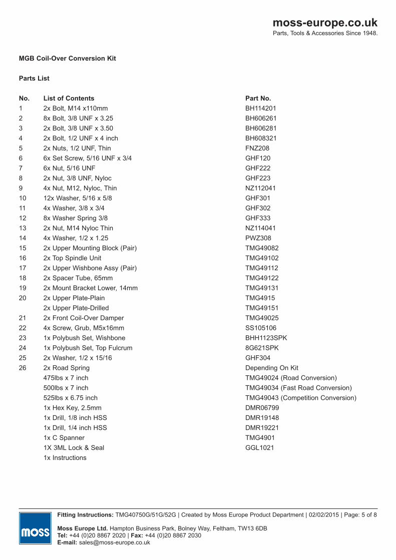
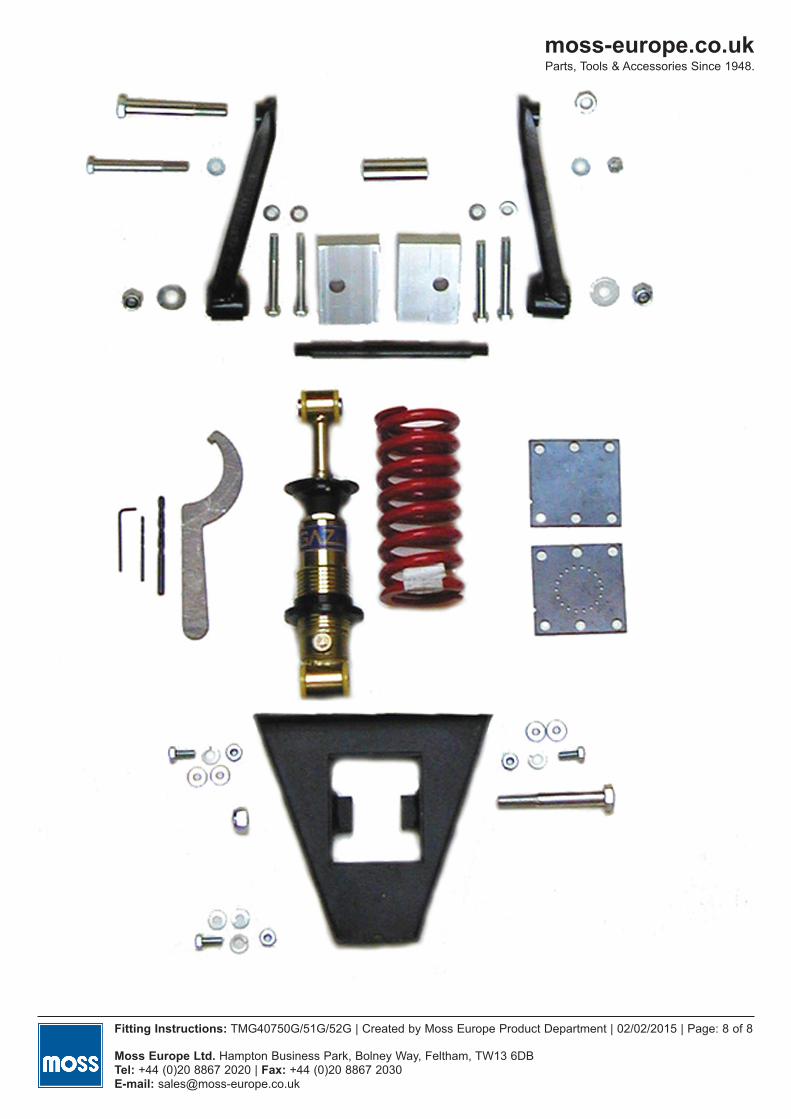
MGB Coil-Over Conversion Kit
Parts List
No. List of Contents Part No.1 2x Bolt, M14 x110mm BH1142012 8x Bolt, 3/8 UNF x 3.25 BH6062613 2x Bolt, 3/8 UNF x 3.50 BH6062814 2x Bolt, 1/2 UNF x 4 inch BH6083215 2x Nuts, 1/2 UNF, Thin FNZ2086 6x Set Screw, 5/16 UNF x 3/4 GHF1207 6x Nut, 5/16 UNF GHF2228 2x Nut, 3/8 UNF, Nyloc GHF2239 4x Nut, M12, Nyloc, Thin NZ11204110 12x Washer, 5/16 x 5/8 GHF30111 4x Washer, 3/8 x 3/4 GHF30212 8x Washer Spring 3/8 GHF33313 2x Nut, M14 Nyloc Thin NZ11404114 4x Washer, 1/2 x 1.25 PWZ30815 2x Upper Mounting Block (Pair) TMG4908216 2x Top Spindle Unit TMG4910217 2x Upper Wishbone Assy (Pair) TMG4911218 2x Spacer Tube, 65mm TMG4912219 2x Mount Bracket Lower, 14mm TMG4913120 2x Upper Plate-Plain TMG4915
2x Upper Plate-Drilled TMG4915121 2x Front Coil-Over Damper TMG4902522 4x Screw, Grub, M5x16mm SS10510623 1x Polybush Set, Wishbone BHH1123SPK24 1x Polybush Set, Top Fulcrum 8G621SPK25 2x Washer, 1/2 x 15/16 GHF30426 2x Road Spring Depending On Kit
475lbs x 7 inch TMG49024 (Road Conversion)500lbs x 7 inch TMG49034 (Fast Road Conversion)525lbs x 6.75 inch TMG49043 (Competition Conversion)1x Hex Key, 2.5mm DMR067991x Drill, 1/8 inch HSS DMR191481x Drill, 1/4 inch HSS DMR192211x C Spanner TMG49011X 3ML Lock & Seal GGL10211x Instructions

moss-europe.co.ukParts, Tools & Accessories Since 1948.
Fitting Instructions: TMG40750G/51G/52G | Created by Moss Europe Product Department | 02/02/2015 | Page: 6 of 8
Moss Europe Ltd. Hampton Business Park, Bolney Way, Feltham, TW13 6DBTel: +44 (0)20 8867 2020 | Fax: +44 (0)20 8867 2030 E-mail: [email protected]
moss-europe.co.ukParts, Tools & Accessories Since 1948.
Fitting Instructions: TMG40750G/51G/52G | Created by Moss Europe Product Department | 02/02/2015 | Page: 7 of 8
Moss Europe Ltd. Hampton Business Park, Bolney Way, Feltham, TW13 6DBTel: +44 (0)20 8867 2020 | Fax: +44 (0)20 8867 2030 E-mail: [email protected]
moss-europe.co.ukParts, Tools & Accessories Since 1948.
Fitting Instructions: TMG40750G/51G/52G | Created by Moss Europe Product Department | 02/02/2015 | Page: 8 of 8
Moss Europe Ltd. Hampton Business Park, Bolney Way, Feltham, TW13 6DBTel: +44 (0)20 8867 2020 | Fax: +44 (0)20 8867 2030 E-mail: [email protected]