moog gmbh hydraulic controls engineering (hce) user …€¦ · moog gmbh hydraulic controls...
TRANSCRIPT

Moog GmbH
Hydraulic Controls Engineering (HCE)
User Manual
Control System
QAIO 2/2 AV
Analog Extension Module with Pulse Input
Version: 1.1 September 2006
MOOG GmbH, HCE filename: QAIO2_2_2_Manual_EN.doc; page 1 of 21

Table of Contents
1 Introduction ............................................................................................................................... 3 2 Short Description....................................................................................................................... 4
2.1 General ................................................................................................................................. 4 2.2 Features ................................................................................................................................ 4 2.3 Outputs/Inputs....................................................................................................................... 4 2.4 Module Status LEDs ............................................................................................................. 4 2.5 Configuration......................................................................................................................... 4 2.6 Actuation ............................................................................................................................... 4 2.7 E-Bus .................................................................................................................................... 4 2.8 Technical Data ...................................................................................................................... 5 2.9 Accessories........................................................................................................................... 6
3 View of the Module and Terminal Assignment.......................................................................... 7 3.1 View of the Module................................................................................................................ 7 3.2 Terminal assignment............................................................................................................. 8
4 Analog Outputs ......................................................................................................................... 9 4.1 Basic Wiring Diagram............................................................................................................ 9 4.2 Specifications ........................................................................................................................ 9 4.3 Reference Voltage Output................................................................................................... 11
5 Analog Inputs .......................................................................................................................... 12 5.1 Basic Wiring Diagram.......................................................................................................... 12 5.2 Specifications ...................................................................................................................... 12 5.3 Connecting Analog Sensors................................................................................................ 14
6 Pulse Input .............................................................................................................................. 19 6.1 Operation of digital inputs of QAIO 2/2: .............................................................................. 19 6.2 Hardware:............................................................................................................................ 19 6.3 Electrical specification:........................................................................................................ 20 6.4 Pulse frequency .................................................................................................................. 20 6.5 Software .............................................................................................................................. 20 6.6 Usage constraints ............................................................................................................... 21
MOOG GmbH, HCE filename: QAIO2_2_2_Manual_EN.doc; page 2 of 21
1 Introduction This user manual is an extension to the User Manual M3000® Control System Control System MSC (Moog Servo Controller) Control Module Pay attention to the chapters “General Information“ and “Safety Instructions“ of this user manual.
MOOG GmbH, HCE filename: QAIO2_2_2_Manual_EN.doc; page 3 of 21

2 Short Description
2.1 General The QAIO 2/2 analog module is used for local extension of the inputs and outputs (I/O) of the Moog Servo Controller (MSC) control module. The analog levels are identical to the levels of the MSC. The module is mounted on a DIN top-hat rail and directly connected to the MSC via the internal extension bus (E-Bus).
2.2 Features Analog I/O extension module with pulse input.
• 2 analog inputs • 2 analog outputs • 1 reference voltage output +10 V • Pulse input • Connection via E-Bus
2.3 Outputs/Inputs • 2 analog inputs, each configurable in the MACS development environment as ±10 V,
±10 mA or 4-20 mA. The inputs are converted in multiplex operation. • 2 analog outputs, each ±10 V, additionally individually configurable in the MACS software
as ±10 mA, ±50 mA or 4–20 mA with wire fault monitoring • 1 reference voltage output
The reference voltage source provides a short circuit protected voltage of +10 V. • 1 pulse input 24 V useable as counter input or frequency measurement input
2.4 Module Status LEDs On the front, 4 LEDs provide information about the status of important module functions.
2.5 Configuration The configuration of the analog I/O is carried out per software via the central control configuration in the Moog Axis Control Software (MACS) development environment. Either the two analog inputs or the pulse input can be used.
2.6 Actuation The I/O of the analog extension module is actuated directly from the MSC (not D136X001-001 and D136E001-001) via the extension bus (E-bus). All input- and output-data are transferred within one cycle of the E-Bus. Therefore the module is perfect for fast control tasks.
2.7 E-Bus One MSC can be extended with a maximum of 7 QAIO 2/2 modules. It is not possible to combine it with QAIO 16/4 on one E-Bus segment.
MOOG GmbH, HCE filename: QAIO2_2_2_Manual_EN.doc; page 4 of 21

2.8 Technical Data Module data QAIO 2/2-AV I/O extension module Order number D137-001-011 Connection to M3000 modules Via E-Bus (10 MHz)
Please note: • It is not possible to connect the module to an MSC
D136X001-001 or D136E001-001 • Combination with QAIO 16/4 V or QAIO 16/4 A on
one E-Bus segment is not possible • All QAIO 2/2 A/V modules must be connected next to
the E-Bus master MSC. Further E-Bus modules may be connected right to the QAIO 2/2 A/V modules.
Connection technique Plug-in terminal strips for screwing or clamping Mounting Mounting rail NS 35/7.5 pursuant to EN 50022 (DIN top-hat
rail) 4 module status LEDs Module functions and diagnosis Dimensions, WxHxD 124 x 170 x 85.5 (attachment dimension: W = 113/118.5) mm
4.88 x 6.69 x 3.37 (attachment dimension: W = 4.45/4.67) inch
Temperature range +5°C (+41°F) to +55°C (+131°F) (operation) and -25°C (-13°F) to +70°C (+158°F) (storage) Mean temperature in operation for 24 hrs.: max. +50°C (+122°F)
Relative air humidity 10 % to 95 % (non-condensing) Operation height Max. 2000 m (6500 ft); storage/transport max. 3000 m
(9800 ft) Standards Operating equipment demands and examinations
IEC 61131-2
Interference emission / immunity EN 61000-6-4 / EN 61000-6-2, industrial part Shock / vibration IEC 60068 part 2-27 / IEC 60068 part 2-6 Protection class / protection system III / IP20 Insulation strength IEC 61131-2; test voltage 500 V DC Energy Supply Voltage supply of module electronics
+24 V DC (18-32 V DC) SELV pursuant to DIN EN 60950-1
Current consumption of module electronics
max. 0.25 A
Potential separation Separate potentials for: module electronics, 24 V energy supply, pulse input
Internal voltages Internally generated via DC/DC converters Protection against reverse polarity Yes Analog Inputs 2 analog inputs 16 Bit; individually configurable in the MACS development
environment as ±10 V, ±10 mA or 4–20 mA; overvoltage protection up to ±36 V
Analog Outputs 2 analog outputs 16 Bit; each ±10 V, additionally individually configurable in
the MACS development environment as ±10 mA, ±50 mA or 4–20 mA Overvoltage protection up to ±36 V; short-circuit protected
MOOG GmbH, HCE filename: QAIO2_2_2_Manual_EN.doc; page 5 of 21

Reference for sensors Reference voltage output +10 V; max. load: 5 mA
Overvoltage protection up to ± 36V; short circuit protected Pulse input Pulse input 24 V digital input can be used as input pursuant to IEC
61131-2 type 1 Positive switching (input OE) or ground switching Either the two analog inputs or the pulse input can be used.
2.9 Accessories Accessories Plug-in terminal strips ( two 18-pole and one 9-pole are required per module) Designation Description Order numberScrew terminal 18-pole Up to max. conductor cross-section of 2.5 mm2
(14 AWG) VK055-018
Screw terminal 9-pole Up to max. conductor cross-section of 2.5 mm2 (14 AWG)
VK055-009
Spring latch clamp 18-pole Up to max. conductor cross-section of 2.5 mm2 (14 AWG)
B95907-018
Spring latch clamp 9-pole Up to max. conductor cross-section of 2.5 mm2 (14 AWG)
B95907-018
MOOG GmbH, HCE filename: QAIO2_2_2_Manual_EN.doc; page 6 of 21

3 View of the Module and Terminal Assignment
3.1 View of the Module
64 65 66 67 68 69 70 71 72
REF AGND SHLD Ai1+ C1a C1b Ai1- AGND SHLD REF AGND SHLD Ai2+ C2a C2b Ai2- AGND SHLD
91 92 93 94 95 96 97 98 99 100 101 102 103 104 105 106 107 108
X4
X6
n.c. Ao1a Ao1b AGND SHLD Ao2a Ao2b AGND SHLD
QAIO 2/2-AV
L1+ Di OutEn
L1+ L1+ M1 M1 L2+ L2+ M2 OutEN
1 2 3 4 5 6 7 8 9 10 11 12 13 14 15 16 17 18 X1
±15V
M2 M2L2+ OE M2L2+ OCn.c.
MOOG GmbH, HCE filename: QAIO2_2_2_Manual_EN.doc; page 7 of 21

3.2 Terminal assignment
QAIO 2/2-AV Terminal Assignment Conn. Term.
Nr. Function Description
1 L1+ +24V Supply Module 2 L1+ +24V Supply Module 3 M1 GND Supply Module 4 M1 GND Supply Module 5 L2+ +24V Supply Digital Output + Sensors 6 L2+ +24V Supply Digital Output + Sensors 7 M2 GND Supply Digital Output + Sensors 8 M2 GND Supply Digital Output + Sensors 9 OutEN Digital Output 'Outputs Enabled' 10 11 12 13 L2+ +24V Supply Sensor 1 14 OE Open Emitter Output Sensor 1 15 M2 GND Supply Sensor 1
Pulse input OE
16 L2+ +24V Supply Sensor 2 17 OC Open Collector Output Sensor 2
X1
18 M2 GND Supply Sensor 2
Pulse input OC
64 n.c. 65 Ao1a Analog Output 1 Voltage Output (referenced to AGND) 66 Ao1b Analog Output 1 Current Output (referenced to AGND) 67 AGND Analog Ground 68 SHLD optional Shield Connection
Analog Output 1
69 Ao2a Analog Output 2 Voltage Output (referenced to AGND) 70 Ao2b Analog Output 2 Current Output (referenced to AGND) 71 AGND Analog Ground
X4
72 SHLD optional Shield Connection
Analog Output 2
91 REF +10V Reference Voltage Output 92 AGND Analog Ground 93 SHLD optional Shield Connection
94 Ai1+ Analog Input 1 non inverting 95 C1a Input Current Sample Resistor (connect to C1b) 96 C1b Input Current Sample Resistor (connect to C1a) 97 Ai1- Analog Input 1 inverting 98 AGND Analog Ground 99 SHLD optional Shield Connection
Analog Input 1
100 REF +10V Reference Voltage Output 101 AGND Analog Ground 102 SHLD optional Shield Connection 103 Ai2+ Analog Input 2 non inverting 104 C2a Input Current Sample Resistor (connect to C2b) 105 C2b Input Current Sample Resistor (connect to C2a) 106 Ai2- Analog Input 2 inverting 107 AGND Analog Ground
X6
108 SHLD optional Shield Connection
Analog Input 2
MOOG GmbH, HCE filename: QAIO2_2_2_Manual_EN.doc; page 8 of 21

4 Analog Outputs
4.1 Basic Wiring Diagram
4.2 Specifications Number of analog outputs 2 Analog output type Voltage output ±10 V nominal Additionally one current output each: configurable as: ±10 mA, ±50 mA or 4–20 mA (each nominal)
The analog outputs are configured in the PLC configuration of the MACS development environment. Output impedance within nominal signal range <0.2 W (voltage output) Approx. 1 MW (current outputs)
MOOG GmbH, HCE filename: QAIO2_2_2_Manual_EN.doc; page 9 of 21

Greatest error over the entire temperature range ±1 % of full scale value Output ranges
nominal minimal maximal LSB Value
±10 V -10,92 V +10,92 V 0,333 mV
±10 mA -10,92 mA +10,92 mA 0,333 µA
±50 mA -54,61 mA +54,61 mA 1,667 µA
4–20 mA +3,262 mA +20,74 mA 0,267 µA
Output Ranges of QAIO 2/2 Analog Outputs Digital resolution 16 bit Data format in the application program 32 bit floating point Load impedance range Voltage output ±10 V: ≥ 1.000 Ω Current output ±10 mA: ≤ 1.000 Ω Current output ±50 mA: ≤ 200 Ω Current output 4–20 mA: ≤ 500 Ω
The load impedance range of the current output 4–20 mA does not comply with IEC 61131-2. (IEC 61131-2 requires a load impedance range of ≤ 600 Ω.) Update time The update time corresponds to the task interval of the application program that actuates the output.
The task interval (and thereby the update time of the outputs) is set in the task configuration of the MACS development environment. Rise time T10/90
Step Output from to
RL typ. T10/90
+10 V -10 V Voltage Output ±10 V -10 V +10 V
≥ 1.000 Ω 60 µs
+10 mA -10 mA ±10 mA -10 mA +10 mA
1.000 Ω 60 µs
+50 mA -50 mA ±50 mA -50 mA +50 mA
200 Ω 125 µs
20 mA 4 mA
Current Output
4-20 mA 4 mA 20 mA
500 Ω 70 µs
Rise time T10/90 of QAIO 2/2 Analog Outputs Protection Continuous short-circuit protection; overvoltage protection up to ±36 V Short-circuit current IKmax Voltage output ±10 V: IKmax = ±15 mA Current output ±10 mA: IKmax = ±10.92 mA Current output ±50 mA: IKmax = ±54.61 mA Current output 4–20 mA: IKmax = ±20.74 mA
MOOG GmbH, HCE filename: QAIO2_2_2_Manual_EN.doc; page 10 of 21

Recommended cable types Use only shielded cables. The shield must be made of copper braiding with at least 80% coverage. The wire must be made of copper with a cross section of at least 0.25 mm2 (23 AWG). In environments with a high amount of disturbance, use cables with twisted pair wires. Calibration The QAIO 2/2 is calibrated at the factory and does not require any additional calibration. Permissible load types Resistive load according to "Load impedance range"
The stability of the current outputs is ensured up to an inductive load of 100 mH.
The stability of the voltage outputs is ensured up to a capacitive load of 10 µF. Output current of the voltage output Max. 10 mA Wire fault monitoring of the analog current outputs The analog current outputs are monitored for wire faults. The status of the wire fault monitoring can be evaluated in the application program.
4.3 Reference Voltage Output Reference voltage +10 V DC Load current Max. 5 mA Precision ±0.3 % of full scale value Temperature coefficient < 280 µV/K Output impedance < 0.2 Ω Protection Continuous short-circuit protection; overvoltage protection up to ±36 V Short-circuit current IKmax = 15 mA (residual current of the terminals 91 (REF) and 100 (REF) of the connector X6)
MOOG GmbH, HCE filename: QAIO2_2_2_Manual_EN.doc; page 11 of 21

5 Analog Inputs
5.1 Basic Wiring Diagram
QAIO 2/2
Basic Wiring Diagram of the Analog Inputs Ai1…Ai2 of the QAIO 2/2 The upper analog input Aix is configured as a voltage input, the lower analog input Aiy as a current input.
An analog input Aix can only be used as a current input if the terminal Cxa is connected to the terminal Cxb. Example: If Ai2 will be used as an analog current input, C2a must be connected to C2b.
Insertion bridges for connecting the QAIO 2/2 terminals Cxa and Cxb are available from Moog as accessories.
5.2 Specifications Number of analog inputs 2 Type of analog inputs Differential, configurable as: ±10 V, ±10 mA or 4–20 mA (each nominal) The analog inputs are configured in the PLC configuration of the MACS development environment. Common-mode properties Common-mode rejection: > 85 dB Common-mode voltage range: ±17 V Input impedance within nominal signal range > 100 kΩ on voltage inputs 200 Ω on current inputs
MOOG GmbH, HCE filename: QAIO2_2_2_Manual_EN.doc; page 12 of 21

Greatest error over the entire temperature range ±0.5 % of full scale value Permissible measurement range
nominal minimal maximal LSB value
±10 V -10,92 V +10,92 V 0,333 mV
±10 mA -10,92 mA +10,92 mA 0,333 µA
4–20 mA +3,262 mA +20,74 mA 0,267 µA
Permissible Measurement Range of QAIO 2/2 analog inputs Max. permissible continuous overload (higher load results in damage) ±36 V on voltage inputs ±36 mA on current inputs (or ±6.4 V without current limiting) Digital resolution 16 bit Data format in the application program 32 bit floating point Output values when below or above measurement range Maximum or minimum values: see “Permissible Measurement Range” Conversion method Successive approximation Duration of conversion per input Typ. 12.5 µs Sampling time The sampling time corresponds to the task interval of the application program that reads the input. All 2 analog inputs are sampled continuously in succession, i.e., every analog input is updated every 25 µs (max. 2 inputs à 12.5 µs of conversion time). The most recent value is used in the application program.
The task interval (and thereby the sampling time of the inputs) is set in the task configuration of the MACS development environment. Protective device Diodes Recommended cable types Use only shielded cables. The shield must be made of copper braiding with at least 80% coverage. The wire must be made of copper with a cross section of at least 0.25 mm2 (23 AWG). In environments with a high amount of disturbance, use cables with twisted pair wires. Calibration The QAIO 2/2 is calibrated at the factory and does not require any additional calibration. Crosstalk between inputs <0.02%
MOOG GmbH, HCE filename: QAIO2_2_2_Manual_EN.doc; page 13 of 21

5.3 Connecting Analog Sensors Recommended cable types Use only shielded cables. The shield must be made of copper braiding with at least 80% coverage. The wire must be made of copper with a cross section of at least 0.25 mm2 (23 AWG). In environments with a high amount of disturbance, use cables with twisted pair wires.
5.3.1 Shielding Signal Cables
Shielding the Signal Cable when Connecting an Analog Sensor to the QAIO 2/2
MOOG GmbH, HCE filename: QAIO2_2_2_Manual_EN.doc; page 14 of 21
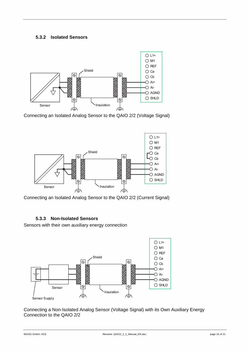
5.3.2 Isolated Sensors
Connecting an Isolated Analog Sensor to the QAIO 2/2 (Voltage Signal)
Connecting an Isolated Analog Sensor to the QAIO 2/2 (Current Signal)
5.3.3 Non-Isolated Sensors Sensors with their own auxiliary energy connection
Connecting a Non-Isolated Analog Sensor (Voltage Signal) with its Own Auxiliary Energy Connection to the QAIO 2/2
MOOG GmbH, HCE filename: QAIO2_2_2_Manual_EN.doc; page 15 of 21

Connecting a Non-Isolated Analog Sensor (Current Signal) with its Own Auxiliary Energy Connection to the QAIO 2/2
Connecting a Non-Isolated Analog Sensor (Voltage Signal) with the Same Auxiliary Energy Connection as the QAIO 2/2
Connecting a Non-Isolated Analog Sensor (Current Signal) with the Same Auxiliary Energy Connection as the QAIO 2/2
MOOG GmbH, HCE filename: QAIO2_2_2_Manual_EN.doc; page 16 of 21
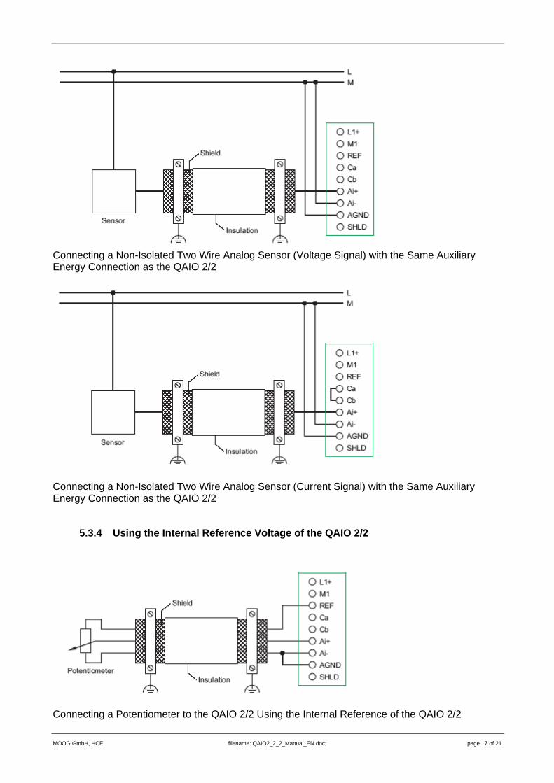
Connecting a Non-Isolated Two Wire Analog Sensor (Voltage Signal) with the Same Auxiliary Energy Connection as the QAIO 2/2
Connecting a Non-Isolated Two Wire Analog Sensor (Current Signal) with the Same Auxiliary Energy Connection as the QAIO 2/2
5.3.4 Using the Internal Reference Voltage of the QAIO 2/2
Connecting a Potentiometer to the QAIO 2/2 Using the Internal Reference of the QAIO 2/2
MOOG GmbH, HCE filename: QAIO2_2_2_Manual_EN.doc; page 17 of 21

Connecting an Analog 4-Wire Sensor to the QAIO 2/2 Using the Internal Reference Voltage of the QAIO 2/2
MOOG GmbH, HCE filename: QAIO2_2_2_Manual_EN.doc; page 18 of 21

6 Pulse Input
6.1 Operation of digital inputs of QAIO 2/2: To use any digital input of the QAIO 2/2, the analog inputs of the module must be disabled. Both digital channels of the QAIO 2/2 are used as pulse counting inputs. In this mode only one of the two inputs can be active. The configuration can be done completely with the MACS software of the E-Bus master module.
6.2 Hardware Digital Input OE:
to eval-uation
L2+
OE
M2
Opto-Decoupling
24 V
DC
Signal-Source
Digital Input OC:
to eval-uation
L2+
OC
M2
Opto-Decoupling
24 V
DC
Signal-Source
MOOG GmbH, HCE filename: QAIO2_2_2_Manual_EN.doc; page 19 of 21

6.3 Electrical specification:
0 State
Transition Area
Typical Characteristic Input Curve of a Digital Input (U vs. I)
1 State
U[V]
I [mA]
0
10
20
30
0 2 4 6 8 10 12 14 16
25
5
15
U/I working ranges of digital inputs:
Rated Voltage Ue = 24V upper limit Ue max = 32V
Digital input OE: Ue = OE – M2 Digital input OC: Ue = L2 – OC (ground reference point: M2) lower limit Ue min = 18V
upper limit UHmax = 30V IHmax = 15mA Limits for the 1 state lower limit UHmin = 15V IHmin = 2mA upper limit ULmax = 15/5V ILmax = 15mA Limits for the 0 state lower limit ULmin = −3V ILmin = ND
6.4 Pulse frequency Pulses with a minimum pulse width of 200ns (5MHz) are detected by the electronics. The counter register value is incremented by 1 at any occurrence of a falling edge at the digital input in use.
6.5 Software Configuration: The configuration of the QAIO 2/2 is done by the E-Bus master module. For that purpose a QAIO 2/2 module must be placed as an E-Bus slave. To use any digital input, the operation mode “Analog input“ has to be changed to “Pulse counter“ or “Frequency measurement“. In both cases the QAIO 2/2 works as a pulse counter. The calculation of the frequency is done by the E-Bus master module. The time base for this calculation is the cycle time of the task with the highest priority.
MOOG GmbH, HCE filename: QAIO2_2_2_Manual_EN.doc; page 20 of 21

6.6 Usage constraints When using QAIO 2/2 modules in a E-Bus chain, it is not possible to use QAIO 16/4 modules at the same time in the same E-Bus group. The MACS software avoids this and displays an error message. When using QAIO 2/2 modules in combination with QDIO 16/16 modules in the same E-Bus group, it is necessary to use the QAIO 2/2 modules close to the E-Bus master and align the QDIO 16/16 modules on the right side of the E-Bus group.
MOOG GmbH, HCE filename: QAIO2_2_2_Manual_EN.doc; page 21 of 21