montageanweisung - hsi 90/hsi 150. instructions de montage ... · abb. hsi 150-k2/240...
TRANSCRIPT
Immer. Sicher. Dicht.
Abb. HSI 150-K2/240
Montageanweisung - HSI 90/HSI 150.
So wird einbetoniert.
EN
FR
NL
PL
DE
Instrukcja montażu - HSI 90/HSI 150.
Prawidłowy sposób zabetonowania.
Montage-instructie - HSI 90/HSI 150.
Inbedden in beton gaat als volgt.
Instructions de montage - HSI 90/HSI 150.
Sceller dans le béton.
Installation Instruction - HSI 90/HSI 150.
How to set in concrete correctly.
2
HSI 90/HSI 150. So wird einbetoniert.DE
• Grundsätzlich sind die national gültigen Verlege und Verfüllvorschriften für Rohre zu beachten.
• Untergrund und Kabelunterbau vor der Kabel-/Rohrverlegung gut verdichten, damit kein Absinken der Kabel möglich ist.
• Falsche Kabel- bzw. Kabelschutzrohrverlegung und unsachgemäßes Verfüllen des Kabelgra-bens führt zu Setzungen und kann dadurch zu Beschädigungen und Undichtigkeiten führen.
• Die Durchführung darf durch Kabel bzw. Rohre nicht mechanisch belastet werden.
• Für die Reinigung der Kabeldurchführungen dürfen keine lösungsmittelhaltigen Reiniger verwendet werden, wir empfehlen den Kabelreiniger KR M.T.X.
• Bei Paketbildung von Rohranschlüssen �a = 160mm empfehlen wir die Verwendung des Abstandhalters HSI-AH 40 für eine optimierte Verdichtung des Betons und die Verdichtung im Kabelgraben (Achsmaßvergrößerung von 210 mm auf 250 mm).
• Weiteres Zubehör und Informationen unter www.hauff-technik.de und in den tech-nischen Datenblättern.
Inhalt
1 Allgemeines und Verwendungszweck2 Allgemeine Hinweise/Sicherheitshinweise3 Beschreibung4 Lieferumfang5 Benötigtes Werkzeug und Hilfsmittel6 Montage
1 Allgemeines und Verwendungszweck
Systemlösungsstandard für Kabelabdichtungen.
2 Allgemeine Hinweise
• Bei Schutzrohranschlüssen wird die Systemsicherheit der Kabeldurchführung auf die Dicht-heit des Schutzrohrsystems reduziert, sofern keine Kabelabdichtung vorgenommen wird.
• Schützen Sie die Dichtpackung bei der Montageinstallation vor Beschädigungen, Feuchte und Verunreinigungen. Überprüfen Sie die Lieferung auf Vollständigkeit und alle Einzelteile und eventuelle Schäden
• Es dürfen nur unbeschädigte Teile montiert werden.
• Bei der Installation müssen die entsprechenden Vorschriften der Berufsgenossenschaften, die VDE-Bestimmungen, die entsprechenden nationalen Sicherheits- und Unfallver-hütungsvorschriften sowie die Richtlinien (Arbeits- und Verfahrensanweisungen) Ihres Unternehmens beachtet werden.
Sicherheitshinweise
3
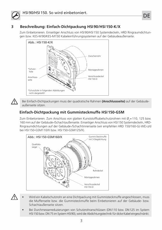
3 Beschreibung: Einfach-Dichtpackung HSI 90/HSI 150-K/X
HSI 90/HSI 150. So wird einbetoniert.DE
Zum Einbetonieren. Einseitiger Anschluss von HSI 90/HSI 150 Systemdeckeln, HRD Ringraumdichtun-gen bzw. KES-M 90/KES-M150 Kabeleinführungssystemen auf der Gebäudeaußenseite.
Montagerahmen
VerschlussdeckelHSI 150-D
Zwischenrohr
Anschluss-seite
Abb.: HSI 150-K/X
*Schutz- folie
*Schutzfolie in folgenden Abbildungen nicht dargestellt!
Bei Einfach-Dichtpackungen muss der quadratische Rahmen (Anschlussseite) auf der Gebäude-außenseite sitzen.
Einfach-Dichtpackung mit Gummisteckmuffe HSI 150-GSM
Zum Einbetonieren. Zum Anschluss von glatten Kunststoffkabelschutzrohren mit �a= 110, 125 bzw. 160 mm auf der Gebäude-/Schachtaußenseite. Einseitiger Anschluss von HSI 150 Systemdeckeln, HRD-Ringraumdichtungen auf der Gebäude-/Schachtinnenseite (wir empfehlen HRD 150/160-G(-WE)-z/d bei HSI 150-GSM110/X bzw. HSI 150-GSM125/X).
• Wird ein Kabelschutzrohr an eine Dichtpackung mit Gummisteckmuffe angeschlossen, muss die Muffenseite bzw. die Gummisteckmuffe beim Einbetonieren auf der Gebäude- bzw. Schachtaußenseite sitzen.
• Bei Durchmesserreduzierungen von Schutzrohranschlüssen (DN 110 bzw. DN 125 im System HSI 150 bzw. DN 75 im System HSI 90), wird die Abdichtungstechnik für dicke Kabel eingeschränkt.
Montagerahmen
VerschlussdeckelHSI 150-D
Qualitäts-siegel
Gummi-Steckmuffe mit 3-Stegdichtung
Abb.: HSI 150-GSM160/X
+49 7322 1333
-0
Rohrdeckel
4
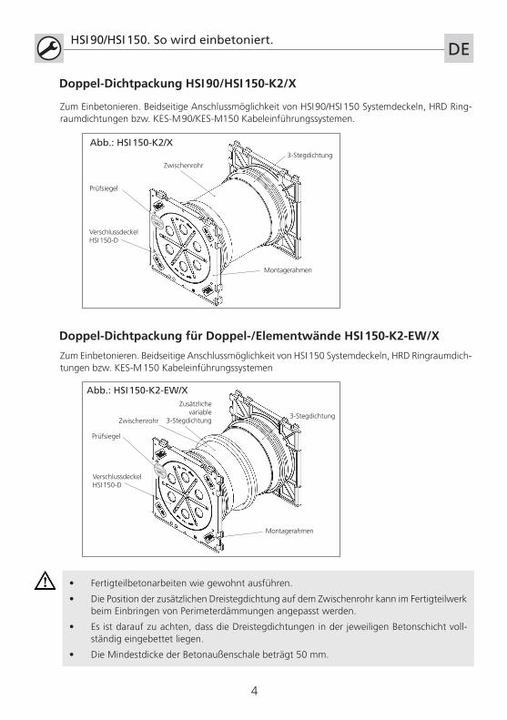
Doppel-Dichtpackung HSI 90/HSI 150-K2/X
HSI 90/HSI 150. So wird einbetoniert.DE
Montagerahmen
VerschlussdeckelHSI 150-D
Prüfsiegel
Zwischenrohr
Zum Einbetonieren. Beidseitige Anschlussmöglichkeit von HSI 90/HSI 150 Systemdeckeln, HRD Ring-raumdichtungen bzw. KES-M 90/KES-M150 Kabeleinführungssystemen.
3-Stegdichtung
+49 7322 1333
-0
Doppel-Dichtpackung für Doppel-/Elementwände HSI 150-K2-EW/X
Zum Einbetonieren. Beidseitige Anschlussmöglichkeit von HSI 150 Systemdeckeln, HRD Ringraumdich-tungen bzw. KES-M 150 Kabeleinführungssystemen
• Fertigteilbetonarbeiten wie gewohnt ausführen.
• Die Position der zusätzlichen Dreistegdichtung auf dem Zwischenrohr kann im Fertigteilwerk beim Einbringen von Perimeterdämmungen angepasst werden.
• Es ist darauf zu achten, dass die Dreistegdichtungen in der jeweiligen Betonschicht voll-ständig eingebettet liegen.
• Die Mindestdicke der Betonaußenschale beträgt 50 mm.
Montagerahmen
VerschlussdeckelHSI 150-D
Prüfsiegel
Zusätzliche variable
3-Stegdichtung3-Stegdichtung
Abb.: HSI 150-K2/X
Abb.: HSI 150-K2-EW/X
+49 7322 1333
-0
Zwischenrohr
5
HSI 90/HSI 150. So wird einbetoniert.DE
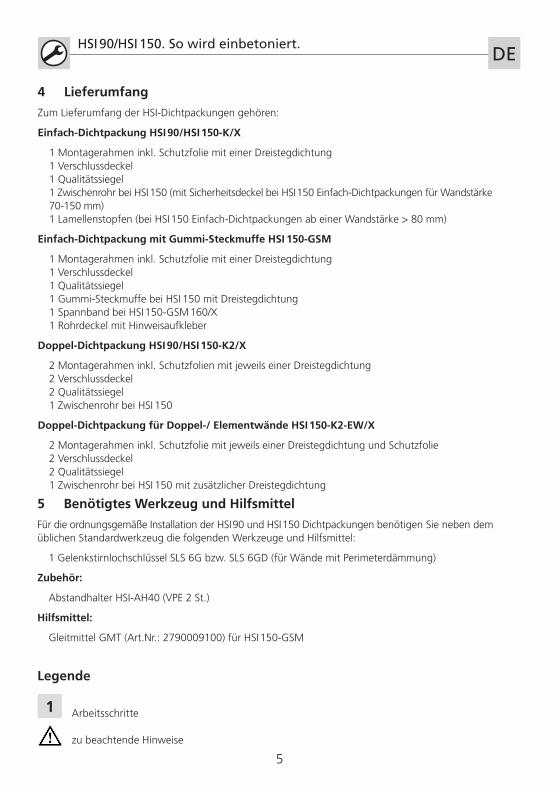
5 Benötigtes Werkzeug und Hilfsmittel
Für die ordnungsgemäße Installation der HSI 90 und HSI 150 Dichtpackungen benötigen Sie neben dem üblichen Standardwerkzeug die folgenden Werkzeuge und Hilfsmittel:
1 Gelenkstirnlochschlüssel SLS 6G bzw. SLS 6GD (für Wände mit Perimeterdämmung)
Zubehör:
Abstandhalter HSI-AH40 (VPE 2 St.)
Hilfsmittel:
Gleitmittel GMT (Art.Nr.: 2790009100) für HSI 150-GSM
4 Lieferumfang
Zum Lieferumfang der HSI-Dichtpackungen gehören:
Einfach-Dichtpackung HSI 90/HSI 150-K/X
1 Montagerahmen inkl. Schutzfolie mit einer Dreistegdichtung 1 Verschlussdeckel 1 Qualitätssiegel 1 Zwischenrohr bei HSI 150 (mit Sicherheitsdeckel bei HSI 150 Einfach-Dichtpackungen für Wandstärke 70-150 mm) 1 Lamellenstopfen (bei HSI 150 Einfach-Dichtpackungen ab einer Wandstärke > 80 mm)
Einfach-Dichtpackung mit Gummi-Steckmuffe HSI 150-GSM
1 Montagerahmen inkl. Schutzfolie mit einer Dreistegdichtung 1 Verschlussdeckel 1 Qualitätssiegel 1 Gummi-Steckmuffe bei HSI 150 mit Dreistegdichtung 1 Spannband bei HSI 150-GSM 160/X 1 Rohrdeckel mit Hinweisaufkleber
Doppel-Dichtpackung HSI 90/HSI 150-K2/X
2 Montagerahmen inkl. Schutzfolien mit jeweils einer Dreistegdichtung 2 Verschlussdeckel 2 Qualitätssiegel 1 Zwischenrohr bei HSI 150
Doppel-Dichtpackung für Doppel-/ Elementwände HSI 150-K2-EW/X
2 Montagerahmen inkl. Schutzfolie mit jeweils einer Dreistegdichtung und Schutzfolie 2 Verschlussdeckel 2 Qualitätssiegel 1 Zwischenrohr bei HSI 150 mit zusätzlicher Dreistegdichtung
1
Legende
Arbeitsschritte
zu beachtende Hinweise
Ach
sab
stan
d25
0 m
m
Ran
dab
stan
d65
mm
6
HSI 90/HSI 150. So wird einbetoniert. DE
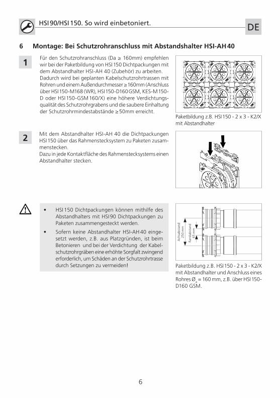
Für den Schutzrohranschluss (Da ≥ 160mm) empfehlen wir bei der Paketbildung von HSI 150 Dichtpackungen mit dem Abstandhalter HSI-AH 40 (Zubehör) zu arbeiten.Dadurch wird bei geplanten Kabelschutzrohrtrassen mit Rohren und einem Außendurchmesser ≥ 160mm (Anschluss über HSI 150-M168 (WR), HSI 150-D160 GSM, KES-M 150-D oder HSI 150-GSM 160/X) eine höhere Verdichtungs-qualität des Schutzrohrgrabens und die saubere Einhaltung der Schutzrohrmindestabstände ≥ 50mm erreicht.
2
• HSI 150 Dichtpackungen können mithilfe des Abstandhalters mit HSI 90 Dichtpackungen zu Paketen zusammengesteckt werden.
• Sofern keine Abstandhalter HSI-AH 40 einge-setzt werden, z.B. aus Platzgründen, ist beim Betonieren und bei der Verdichtung der Kabel-schutzrohrgräben eine erhöhte Sorgfalt zwingend erforderlich, um Schäden an der Schutzrohrtrasse durch Setzungen zu vermeiden!
Mit dem Abstandhalter HSI-AH 40 die Dichtpackungen HSI 150 über das Rahmenstecksystem zu Paketen zusam-menstecken. Dazu in jede Kontaktfläche des Rahmenstecksystems einen Abstandhalter stecken.
Paketbildung z.B. HSI 150 - 2 x 3 - K2/X mit Abstandhalter und Anschluss eines Rohres �a = 160 mm, z.B. über HSI 150-D160 GSM.
1
6 Montage: Bei Schutzrohranschluss mit Abstandshalter HSI-AH 40
Paketbildung z.B. HSI 150 - 2 x 3 - K2/X mit Abstandhalter
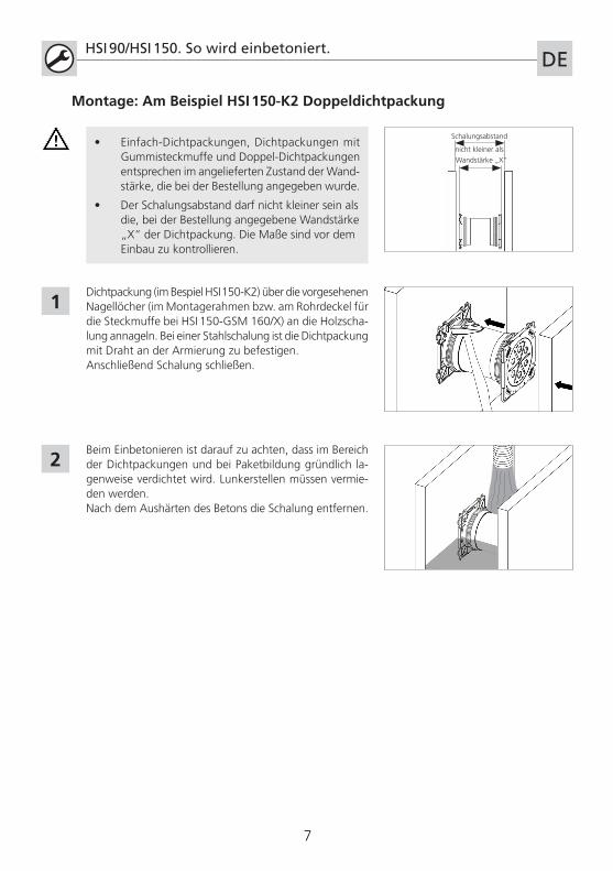
Schalungsabstand
nicht kleiner als
Wandstärke „X“
7
HSI 90/HSI 150. So wird einbetoniert.DE
Dichtpackung (im Bespiel HSI 150-K2) über die vorgesehenen Nagellöcher (im Montagerahmen bzw. am Rohrdeckel für die Steckmuffe bei HSI 150-GSM 160/X) an die Holzscha-lung annageln. Bei einer Stahlschalung ist die Dichtpackung mit Draht an der Armierung zu befestigen. Anschließend Schalung schließen.
1
2Beim Einbetonieren ist darauf zu achten, dass im Bereich der Dichtpackungen und bei Paketbildung gründlich la-genweise verdichtet wird. Lunkerstellen müssen vermie-den werden. Nach dem Aushärten des Betons die Schalung entfernen.
Montage: Am Beispiel HSI 150-K2 Doppeldichtpackung
• Einfach-Dichtpackungen, Dichtpackungen mit Gummisteckmuffe und Doppel-Dichtpackungen entsprechen im angelieferten Zustand der Wand-stärke, die bei der Bestellung angegeben wurde.
• Der Schalungsabstand darf nicht kleiner sein als die, bei der Bestellung angegebene Wandstärke „X“ der Dichtpackung. Die Maße sind vor dem Einbau zu kontrollieren.
8
HSI 90/HSI 150. So wird einbetoniert. DE
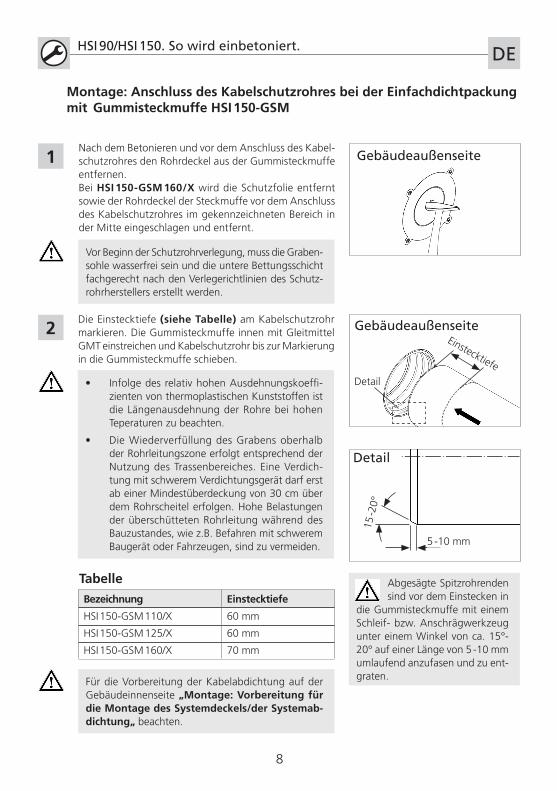
Die Einstecktiefe (siehe Tabelle) am Kabelschutzrohr markieren. Die Gummisteckmuffe innen mit Gleitmittel GMT einstreichen und Kabelschutzrohr bis zur Markierung in die Gummisteckmuffe schieben.
Bezeichnung Einstecktiefe
HSI 150-GSM 110/X 60 mm
HSI 150-GSM 125/X 60 mm
HSI 150-GSM 160/X 70 mm
Tabelle
2
Nach dem Betonieren und vor dem Anschluss des Kabel-schutzrohres den Rohrdeckel aus der Gummisteckmuffe entfernen.Bei HSI 150-GSM 160/X wird die Schutzfolie entfernt sowie der Rohrdeckel der Steckmuffe vor dem Anschluss des Kabelschutzrohres im gekennzeichneten Bereich in der Mitte eingeschlagen und entfernt.
1
Für die Vorbereitung der Kabelabdichtung auf der Gebäudeinnenseite „Montage: Vorbereitung für die Montage des Systemdeckels/der Systemab-dichtung„ beachten.
Montage: Anschluss des Kabelschutzrohres bei der Einfachdichtpackung mit Gummisteckmuffe HSI 150-GSM
Gebäudeaußenseite
Vor Beginn der Schutzrohrverlegung, muss die Graben-sohle wasserfrei sein und die untere Bettungsschicht fachgerecht nach den Verlegerichtlinien des Schutz-rohrherstellers erstellt werden.
• Infolge des relativ hohen Ausdehnungskoeffi-zienten von thermoplastischen Kunststoffen ist die Längenausdehnung der Rohre bei hohen Teperaturen zu beachten.
• Die Wiederverfüllung des Grabens oberhalb der Rohrleitungszone erfolgt entsprechend der Nutzung des Trassenbereiches. Eine Verdich-tung mit schwerem Verdichtungsgerät darf erst ab einer Mindestüberdeckung von 30 cm über dem Rohrscheitel erfolgen. Hohe Belastungen der überschütteten Rohrleitung während des Bauzustandes, wie z.B. Befahren mit schwerem Baugerät oder Fahrzeugen, sind zu vermeiden.
Abgesägte Spitzrohrenden sind vor dem Einstecken in
die Gummisteckmuffe mit einem Schleif- bzw. Anschrägwerkzeug unter einem Winkel von ca. 15°-20° auf einer Länge von 5 -10 mm umlaufend anzufasen und zu ent-graten.
GebäudeaußenseiteEinstecktiefe
Detail
Detail
5 -10 mm
15 -2
0°
HSI 90/HSI 150. So wird einbetoniert. DE
9
Unsere Produkte sind entsprechend ihrer vorgesehenen Verwendungsweise ausschließlich für den Einbau in Bauwerke entwickelt, deren Baustoffe dem derzeitigen Stand der Technik ent-sprechen. Für eine andere oder darüber hinaus gehende Verwendung, sofern sie nach Rück-sprache mit uns nicht ausdrücklich schriftlich bestätigt wurde, übernehmen wir keine Haftung.
Änderungen vorbehalten.Service-Telefon +49 7322 1333-0
2
1
• Den Verschlussdeckel der Dichtpackung erst unmittelbar vor der Kabelbelegung öffnen. Montageanweisung für Systemdeckel beachten.
• Nicht benötigte Kabeldurchführungen können bei unbeschädigtem Hauff-Qualitätssiegel auf dem Verschlussdeckel als druckdichte Reservedurchführungen genutzt werden.
• Verschlussdeckel nicht mit Hammer oder scharfem Gegenstand einschlagen!
• Geöffnete Kabeldurchführungen, welche als Reservedurchführungen genutzt werden sollen bzw. Verschlussdeckel, die versehentlich geöffnet wurden, sind grundsätzlich mit neuen Verschlussdeckeln HSI 150-D bzw. HSI 90 auszurüsten!
• Demontierte bzw. beschädigte Verschlussdeckel dürfen nicht wieder verwendet werden!
Montage: Vorbereitung für die Montage des Systemdeckels/der System-abdichtung
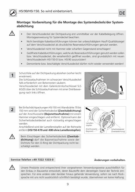
Schutzfolie auf der Dichtpackung abziehen (vorher leicht erwärmen).Die Schlüsselaufnahmen im schwarzen Verschlussdeckel falls erforderlich von Betonresten säubern.Verschlussdeckel mit dem Gelenkstirnlochschlüssel SLS 6G(D) über die Schlüsselaufnahmen mit einer Drehbewe-gung nach links öffnen.
Bei Einfachdichtpackungen HSI 150 mit Wandstärke 70 bis 150 mm wird der Sicherheitsdeckel (Zweitabdichtung) auf der Anschlussseite (Bajonettaufnahme) mit einem Hammer eingeschlagen und entfernt. Optional kann der Sicherheitsdeckeldeckel auch rückseitig eingeschlagen werden.Anschließend wird der Lamellenstopfen auf der Rohrseite entfernt (HSI 150-K70 und -K80 ohne Lamellenstopfen). Anschlussseite
(Bajonett)Sicherheitsdeckel (Zweitabdichtung)
Lamellen-stopfen
Beim Einschlagen des Sicherheitsdeckels (Zweitab-dichtung) darf die Bajonettaufnahme sowie der Dichtsitz für den O-Ring der Dichtpackung nicht be-schädigt werden.
HSI 90/HSI 150. How to set in concrete correctly.EN
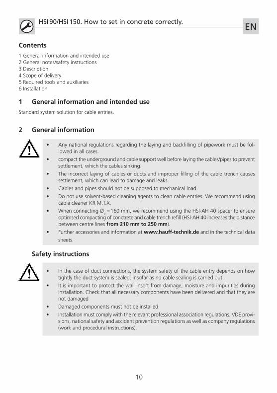
• Any national regulations regarding the laying and backfilling of pipework must be fol-lowed in all cases.
• compact the underground and cable support well before laying the cables/pipes to prevent settlement, which the cables sinking.
• The incorrect laying of cables or ducts and improper filling of the cable trench causes settlement, which can lead to damage and leaks.
• Cables and pipes should not be supposed to mechanical load.
• Do not use solvent-based cleaning agents to clean cable entries. We recommend using cable cleaner KR M.T.X.
• When connecting �a = 160 mm, we recommend using the HSI-AH 40 spacer to ensure optimsed compacting of conctrete and cable trench refill (HSI-AH 40 increases the distance between centre lines from 210 mm to 250 mm).
• Further accessories and information at www.hauff-technik.de and in the technical data
sheets.
Contents
1 General information and intended use2 General notes/safety instructions3 Description4 Scope of delivery5 Required tools and auxiliaries6 Installation
1 General information and intended use
Standard system solution for cable entries.
2 General information
• In the case of duct connections, the system safety of the cable entry depends on how tightly the duct system is sealed, insofar as no cable sealing is carried out.
• It is important to protect the wall insert from damage, moisture and impurities during installation. Check that all necessary components have been delivered and that they are not damaged
• Damaged components must not be installed.
• Installation must comply with the relevant professional association regulations, VDE provi-sions, national safety and accident prevention regulations as well as company regulations (work and procedural instructions).
Safety instructions
10
3 Description: Single wall insert HSI 90/HSI 150-K/X
HSI 90/HSI 150. How to set in concrete correctly.EN
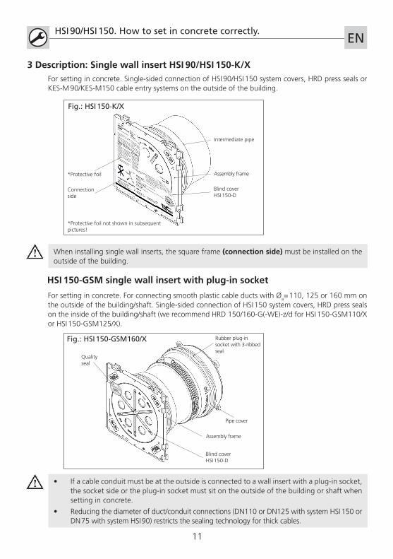
For setting in concrete. Single-sided connection of HSI 90/HSI 150 system covers, HRD press seals or KES-M 90/KES-M150 cable entry systems on the outside of the building.
Assembly frame
Blind coverHSI 150-D
Intermediate pipe
Connection side
Fig.: HSI 150-K/X
*Protective foil
*Protective foil not shown in subsequent pictures!
When installing single wall inserts, the square frame (connection side) must be installed on the outside of the building.
HSI 150-GSM single wall insert with plug-in socket
For setting in concrete. For connecting smooth plastic cable ducts with �a= 110, 125 or 160 mm on the outside of the building/shaft. Single-sided connection of HSI 150 system covers, HRD press seals on the inside of the building/shaft (we recommend HRD 150/160-G(-WE)-z/d for HSI 150-GSM110/X or HSI 150-GSM125/X).
• If a cable conduit must be at the outside is connected to a wall insert with a plug-in socket, the socket side or the plug-in socket must sit on the outside of the building or shaft when setting in concrete.
• Reducing the diameter of duct/conduit connections (DN110 or DN125 with system HSI 150 or DN 75 with system HSI 90) restricts the sealing technology for thick cables.
Assembly frame
Blind coverHSI 150-D
Quality seal
Rubber plug-in socket with 3-ribbed seal
Fig.: HSI 150-GSM160/X
+49 7322 1333
-0
Pipe cover
11
Double wall insert HSI 90/HSI 150-K2/X
HSI 90/HSI 150. How to set in concrete correctly.EN
Assembly frame
Blind coverHSI 150-D
Quality seal
Intermediate pipe
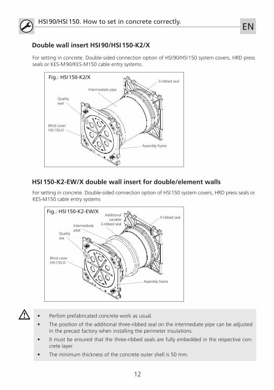
For setting in concrete. Double-sided connection option of HSI 90/HSI 150 system covers, HRD press seals or KES-M 90/KES-M150 cable entry systems.
3-ribbed seal
+49 7322 1333
-0
HSI 150-K2-EW/X double wall insert for double/element walls
For setting in concrete. Double-sided connection option of HSI 150 system covers, HRD press seals or KES-M150 cable entry systems
• Perfom prefabricated concrete work as usual.
• The position of the additional three-ribbed seal on the intermediate pipe can be adjusted in the precast factory when installing the perimeter insulations.
• It must be ensured that the three-ribbed seals are fully embedded in the respective con-crete layer.
• The minimum thickness of the concrete outer shell is 50 mm.
Assembly frame
Blind coverHSI 150-D
Quality sea
Additional variable
3-ribbed seal
3-ribbed seal
Fig.: HSI 150-K2/X
Fig.: HSI 150-K2-EW/X
+49 7322 1333
-0
Intermediate pipe
12
HSI 90/HSI 150. How to set in concrete correctly.EN
5 Required tool and auxiliaries
To install the HSI 90 and HSI 150 wall inserts correctly, you will need the following tools and auxiliaries in addition to the usual tools:
1 flexible socket spanner SLS 6G or SLS 6GD (for walls with perimeter insulation)
Accessories:
HSI-AH40 spacer (VPE 2x)
Auxiliaries:
GMT lubricant (Article number: 2790009100) for HSI 150-GSM
4 Scope of delivery
The scope of delivery of the HSI wall inserts includes:
Single wall insert HSI 90/HSI 150-K/X
1 assembly frame, incl. protective foil with a three-ribbed seal 1 Blind cover 1 quality seal 1 Intermediate pipe for HSI 150 (with safety cover for HSI 150 single wall inserts for wall thicknesses 70-150 mm) 1 lamella plug (for HSI 150 single wall inserts from a wall thickness > 80 mm)
HSI 150-GSM single wall insert with rubber plug-in socket
1 assembly frame, incl. protective film with a three-ribbed seal 1 Blind cover 1 quality seal 1 plug-in socket for HSI 150 with three-ribbed seal 1 clamping strap for HSI 150-GSM 160/X 1 Pipe cover plug with instruction label
Double wall insert HSI 90/HSI 150-K2/X
2 assembly frames incl. protective foils, each with a three-ribbed seal 2 Blind covers 2 quality seals 1 intermediate pipe for HSI 150
HSI 150-K2-EW/X double wall insert for double/element walls
2 assembly frames, incl. protective foil, each with a three-ribbed seal and protective film 2 Blind covers 2 quality seals 1 intermediate pipe for HSI 150 with additional three-ribbed seal
1
Legend
Workflow
Important information
13
Cen
tre
dist
ance
250
mm
Dis
tanc
e fr
om
ed
ge
65 m
m
HSI 90/HSI 150. How to set in concrete correctly.EN
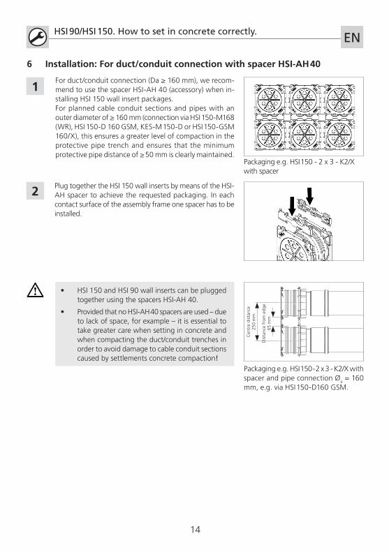
For duct/conduit connection (Da ≥ 160 mm), we recom-mend to use the spacer HSI-AH 40 (accessory) when in-stalling HSI 150 wall insert packages.For planned cable conduit sections and pipes with an outer diameter of ≥ 160 mm (connection via HSI 150-M168 (WR), HSI 150-D 160 GSM, KES-M 150-D or HSI 150-GSM 160/X), this ensures a greater level of compaction in the protective pipe trench and ensures that the minimum protective pipe distance of ≥ 50 mm is clearly maintained.
2
• HSI 150 and HSI 90 wall inserts can be plugged together using the spacers HSI-AH 40.
• Provided that no HSI-AH 40 spacers are used – due to lack of space, for example – it is essential to take greater care when setting in concrete and when compacting the duct/conduit trenches in order to avoid damage to cable conduit sections caused by settlements concrete compaction!
Plug together the HSI 150 wall inserts by means of the HSI-AH spacer to achieve the requested packaging. In each contact surface of the assembly frame one spacer has to be installed.
Packaging e.g. HSI 150 - 2 x 3 - K2/X with spacer and pipe connection �a = 160 mm, e.g. via HSI 150-D160 GSM.
1
6 Installation: For duct/conduit connection with spacer HSI-AH 40
Packaging e.g. HSI 150 - 2 x 3 - K2/X with spacer
14
Formwork spacing
no smaller than
wall thickness "X"
HSI 90/HSI 150. How to set in concrete correctly.EN
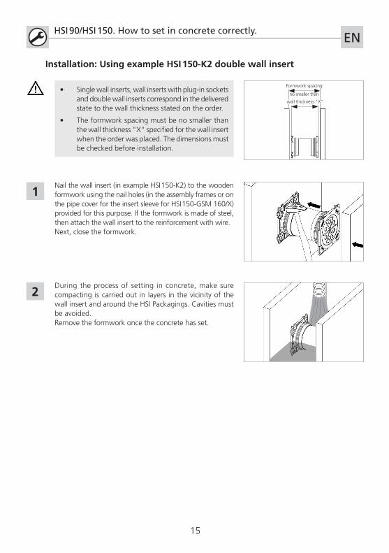
Nail the wall insert (in example HSI 150-K2) to the wooden formwork using the nail holes (in the assembly frames or on the pipe cover for the insert sleeve for HSI 150-GSM 160/X) provided for this purpose. If the formwork is made of steel, then attach the wall insert to the reinforcement with wire. Next, close the formwork.
1
2During the process of setting in concrete, make sure compacting is carried out in layers in the vicinity of the wall insert and around the HSI Packagings. Cavities must be avoided. Remove the formwork once the concrete has set.
Installation: Using example HSI 150-K2 double wall insert
• Single wall inserts, wall inserts with plug-in sockets and double wall inserts correspond in the delivered state to the wall thickness stated on the order.
• The formwork spacing must be no smaller than the wall thickness "X" specified for the wall insert when the order was placed. The dimensions must be checked before installation.
15
HSI 90/HSI 150. How to set in concrete correctly. EN
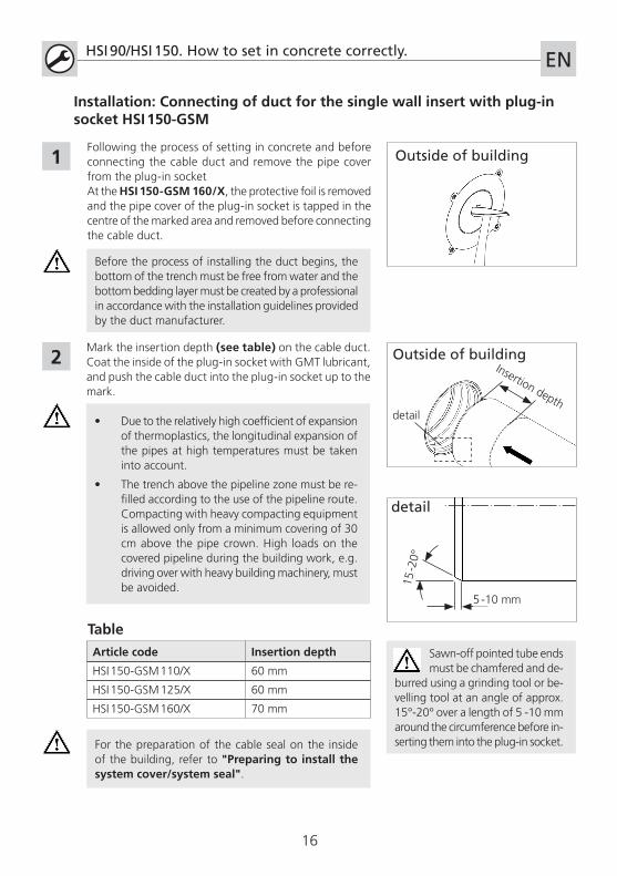
Mark the insertion depth (see table) on the cable duct. Coat the inside of the plug-in socket with GMT lubricant, and push the cable duct into the plug-in socket up to the mark.
Article code Insertion depth
HSI 150-GSM 110/X 60 mm
HSI 150-GSM 125/X 60 mm
HSI 150-GSM 160/X 70 mm
Table
2
Following the process of setting in concrete and before connecting the cable duct and remove the pipe cover from the plug-in socketAt the HSI 150-GSM 160/X, the protective foil is removed and the pipe cover of the plug-in socket is tapped in the centre of the marked area and removed before connecting the cable duct.
1
For the preparation of the cable seal on the inside of the building, refer to "Preparing to install the system cover/system seal".
Installation: Connecting of duct for the single wall insert with plug-in socket HSI 150-GSM
Outside of building
Outside of buildingInsertion depth
Before the process of installing the duct begins, the bottom of the trench must be free from water and the bottom bedding layer must be created by a professional in accordance with the installation guidelines provided by the duct manufacturer.
• Due to the relatively high coefficient of expansion of thermoplastics, the longitudinal expansion of the pipes at high temperatures must be taken into account.
• The trench above the pipeline zone must be re-filled according to the use of the pipeline route. Compacting with heavy compacting equipment is allowed only from a minimum covering of 30 cm above the pipe crown. High loads on the covered pipeline during the building work, e.g. driving over with heavy building machinery, must be avoided.
detail
16
Sawn-off pointed tube ends must be chamfered and de-
burred using a grinding tool or be-velling tool at an angle of approx. 15°-20° over a length of 5 -10 mm around the circumference before in-serting them into the plug-in socket.
detail
5 -10 mm
15 -2
0°
HSI 90/HSI 150. How to set in concrete correctly. EN
As indicated in the instructions for use, our products have been designed exclusively for in-stallation in buildings made from state-of-the-art construction materials. We do not accept liability for use deviating from or beyond this unless our express written confirmation has been obtained in advance.
Subject to change.Service telephone +49 7322 1333-0
2
1
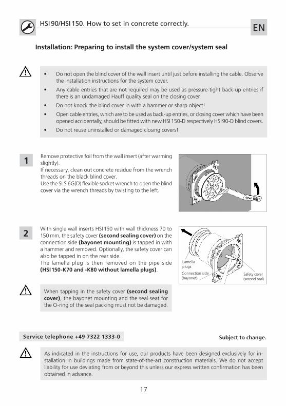
• Do not open the blind cover of the wall insert until just before installing the cable. Observe the installation instructions for the system cover.
• Any cable entries that are not required may be used as pressure-tight back-up entries if there is an undamaged Hauff quality seal on the closing cover.
• Do not knock the blind cover in with a hammer or sharp object!
• Open cable entries, which are to be used as back-up entries, or closing cover which have been opened accidentally, should be fitted with new HSI 150-D respectively HSI 90-D blind covers.
• Do not reuse uninstalled or damaged closing covers!
Installation: Preparing to install the system cover/system seal
Remove protective foil from the wall insert (after warming slightly).If necessary, clean out concrete residue from the wrench threads on the black blind cover.Use the SLS 6G(D) flexible socket wrench to open the blind cover via the wrench threads by twisting to the left.
With single wall inserts HSI 150 with wall thickness 70 to 150 mm, the safety cover (second sealing cover) on the connection side (bayonet mounting) is tapped in with a hammer and removed. Optionally, the safety cover can also be tapped in on the rear side.The lamella plug is then removed on the pipe side (HSI 150-K70 and -K80 without lamella plugs).
Connection side(bayonet)
Safety cover (second seal)
Lamella plugs
When tapping in the safety cover (second sealing cover), the bayonet mounting and the seal seat for the O-ring of the seal packing must not be damaged.
17
18
HSI 90/HSI 150. Sceller dans le béton.FR
• Toujours respecter les prescriptions nationales en mati�re de pose et de remplissage pour les tubes.
• Bien étanchéifier le support et la sous-structure du câble/tube afin d'emp�cher tout affaissement des câbles.
• La pose incorrecte des câbles ou des tubes de protection de câbles et la garniture non conforme de la tranchée de câbles entraînent l'affaissement et peut provoquer des dégâts ou mettre en cause l'étanchéité.
• Le passage ne doit pas �tre endommagé mécaniquement par les câbles ou les tubes.
• Aucun produit � base de solvant ne doit �tre utilisé pour le nettoyage des passe-câbles; nous recommandons le produit nettoyant pour câbles KR M.T.X.
• Pour la formation de passages de raccordement de gaines �a = 160 mm, il est recommandé d'utiliser une entretoise HSI-AH 40 pour assurer une étanchéité optimisée du béton et, ultérieurement, de procéder � l'étanchéité de la tranchée de câbles (agrandissement de la dimension de l'axe de 210 mm à 250 mm).
• D‘autres accessoires et informations sont disponibles sous www.hauff-technik.de et dans les fiches techniques.
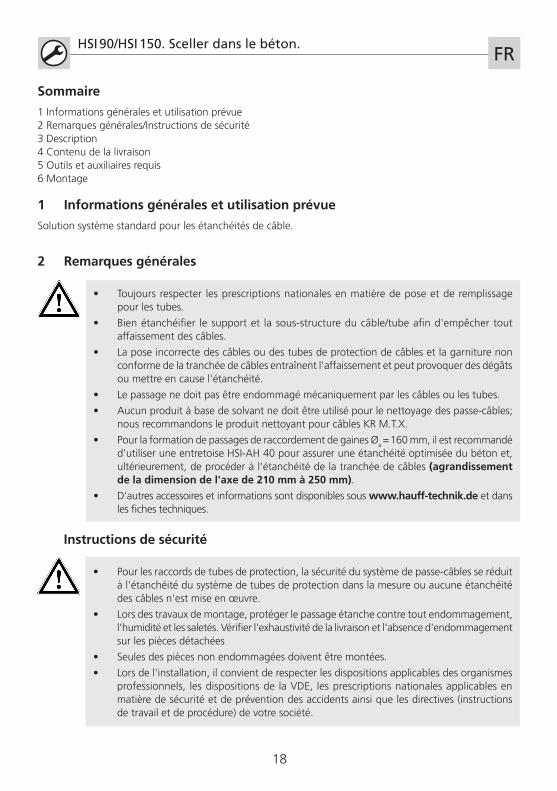
Sommaire
1 Informations générales et utilisation prévue2 Remarques générales/Instructions de sécurité3 Description4 Contenu de la livraison5 Outils et auxiliaires requis6 Montage
1 Informations générales et utilisation prévue
Solution syst�me standard pour les étanchéités de câble.
2 Remarques générales
• Pour les raccords de tubes de protection, la sécurité du syst�me de passe-câbles se réduit � l'étanchéité du syst�me de tubes de protection dans la mesure ou aucune étanchéité des câbles n'est mise en uvre.
• Lors des travaux de montage, protéger le passage étanche contre tout endommagement, l'humidité et les saletés. Vérifier l'exhaustivité de la livraison et l'absence d'endommagement sur les pi�ces détachées
• Seules des pi�ces non endommagées doivent �tre montées.
• Lors de l'installation, il convient de respecter les dispositions applicables des organismes professionnels, les dispositions de la VDE, les prescriptions nationales applicables en mati�re de sécurité et de prévention des accidents ainsi que les directives (instructions de travail et de procédure) de votre société.
Instructions de sécurité
19
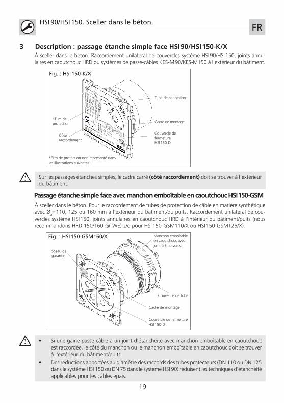
3 Description : passage étanche simple face HSI 90/HSI 150-K/X
HSI 90/HSI 150. Sceller dans le béton.FR
� sceller dans le béton. Raccordement unilatéral de couvercles syst�me HSI 90/HSI 150, joints annu-laires en caoutchouc HRD ou syst�mes de passe-câbles KES-M 90/KES-M150 � l'extérieur du bâtiment.
Cadre de montage
Couvercle de fermetureHSI 150-D
Tube de connexion
Côté raccordement
Fig. : HSI 150-K/X
*Film de protection
*Film de protection non représenté dans les illustrations suivantes!
Sur les passages étanches simples, le cadre carré (côté raccordement) doit se trouver � l'extérieur du bâtiment.
Passage étanche simple face avec manchon emboîtable en caoutchouc HSI 150-GSM� sceller dans le béton. Pour le raccordement de tubes de protection de câble en mati�re synthétique avec �a= 110, 125 ou 160 mm � l'extérieur du bâtiment/du puits. Raccordement unilatéral de cou-vercles syst�me HSI 150, joints annulaires en caoutchouc HRD � l'intérieur du bâtiment/puits (nous recommandons HRD 150/160-G(-WE)-z/d pour HSI 150-GSM110/X ou HSI 150-GSM125/X).
• Si une gaine passe-câble � un joint d‘étanchéité avec manchon emboîtable en caoutchouc est raccordée, le côté du manchon ou le manchon emboîtable en caoutchouc doit se trouver � l'extérieur du bâtiment/puits.
• Des réductions apportées au diam�tre des raccords des tubes protecteurs (DN 110 ou DN 125 dans le syst�me HSI 150 ou DN 75 dans le syst�me HSI 90) réduisent les techniques d'étanchéité applicables pour les câbles épais.
Cadre de montage
Couvercle de fermetureHSI 150-D
Sceau de garantie
Manchon emboîtable en caoutchouc avec joint � 3 nervures
Fig. : HSI 150-GSM160/X
+49 7322 1333
-0
Couvercle de tube
20
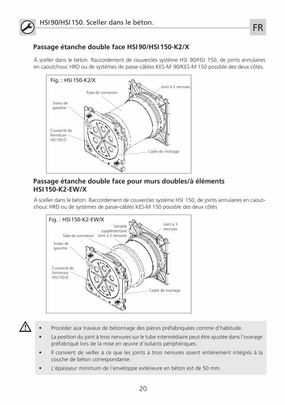
Passage étanche double face HSI 90/HSI 150-K2/X
HSI 90/HSI 150. Sceller dans le béton.FR
Cadre de montage
Couvercle de fermetureHSI 150-D
Sceau de garantie
Tube de connexion
� sceller dans le béton. Raccordement de couvercles syst�me HSI 90/HSI 150, de joints annulaires en caoutchouc HRD ou de syst�mes de passe-câbles KES-M 90/KES-M 150 possible des deux côtés.
Joint � 3 nervures
+49 7322 1333
-0
Passage étanche double face pour murs doubles/à éléments HSI 150-K2-EW/X
� sceller dans le béton. Raccordement de couvercles syst�me HSI 150, de joints annulaires en caout-chouc HRD ou de syst�mes de passe-câbles KES-M 150 possible des deux côtés
• Procéder aux travaux de bétonnage des pi�ces préfabriquées comme d'habitude.
• La position du joint � trois nervures sur le tube intermédiaire peut �tre ajustée dans l'ouvrage préfabriqué lors de la mise en uvre d'isolants périphériques.
• Il convient de veiller � ce que les joints � trois nervures soient enti�rement intégrés � la couche de béton correspondante.
• L'épaisseur minimum de l'enveloppe extérieure en béton est de 50 mm.
Cadre de montage
Couvercle de fermetureHSI 150-D
Sceau de garantie
Variable supplémentaire
Joint � 3 nervures
Joint � 3 nervures
Fig. : HSI 150-K2/X
Fig. : HSI 150-K2-EW/X
+49 7322 1333
-0
Tube de connexion
21
HSI 90/HSI 150. Sceller dans le béton.FR
5 Outils et auxiliaires requis
Pour installer correctement les passages étanches HSI 90 et HSI 150, les outils et dispositifs d'aide suivants sont nécessaires en plus des outils standard :
1 clé � double ergot rond axial articulée SLS 6G ou SLS 6GD (pour murs � isolation périmétrique)
Accessoires :
Entretoise HSI-AH40 (VPE 2 St.)
Dispositifs d'aide :
Lubrifiant GMT (Numéro d‘article: 2790009100) pour HSI 150-GSM
4 Contenu de la livraison
La livraison des passages étanches HSI comprend :
Passage étanche simple face HSI 90/HSI 150-K/X
1 cadre de montage, y compris film de protection avec joint � trois nervures 1 couvercle 1 Sceau de garantie 1 Tube de connexion au HSI150 avec couvercle de sécurité pour passages étanches simple face HSI 150 pour une épaisseur de paroi de 70-150 mm 1 bouchon � lamelles (pour passages étanches simple face HSI 150 � partir d'une épaisseur de paroi > 80 mm)
Passage étanche simple face avec manchon emboîtable en caoutchouc HSI 150-GSM
1 cadre de montage, y compris film de protection avec joint � trois nervures 1 couvercle 1 Sceau de garantie 1 manchon emboîtable en caoutchouc avec joint � trois nervures 1 collier de serrage pour HSI 150-GSM 160/X 1 Couvercle de tube avec autocollant d'avertissement
Passage étanche double face HSI 90/HSI 150-K2/X
2 cadres de montage y compris film de protection avec joints � trois nervures 2 couvercles 2 Sceau de garantie 1 Tube de connexion au HSI150
Passage étanche double face pour murs doubles/à éléments HSI 150-K2-EW/X
2 cadres de montage, y compris film de protection avec joint � trois nervures et film de protection 2 couvercles 2 Sceau de garantie 1 Tube de connexion au HSI150 avec joint � trois nervures supplémentaire
1
Légende
Flux de travail
Remarques � respecter
22
Entr
axe
250
mm
Dis
tanc
e au
bo
rd65
mm
HSI 90/HSI 150. Sceller dans le béton. FR
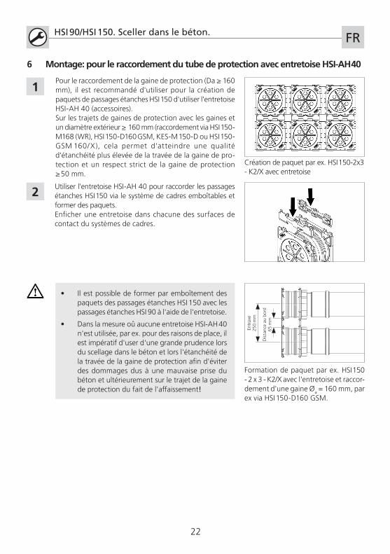
Pour le raccordement de la gaine de protection (Da ≥ 160 mm), il est recommandé d'utiliser pour la création de paquets de passages étanches HSI 150 d'utiliser l'entretoise HSI-AH 40 (accessoires).Sur les trajets de gaines de protection avec les gaines et un diam�tre extérieur ≥ 160 mm (raccordement via HSI 150-M168 (WR), HSI 150-D160 GSM, KES-M 150-D ou HSI 150-GSM 160/X), cela permet d'atteindre une qualité d'étanchéité plus élevée de la travée de la gaine de pro-tection et un respect strict de la gaine de protection ≥ 50 mm.
2
• Il est possible de former par emboîtement des paquets des passages étanches HSI 150 avec les passages étanches HSI 90 � l'aide de l'entretoise.
• Dans la mesure où aucune entretoise HSI-AH 40 n'est utilisée, par ex. pour des raisons de place, il est impératif d'user d'une grande prudence lors du scellage dans le béton et lors l'étanchéité de la travée de la gaine de protection afin d'éviter des dommages dus � une mauvaise prise du béton et ultérieurement sur le trajet de la gaine de protection du fait de l'affaissement!
Utiliser l'entretoise HSI-AH 40 pour raccorder les passages étanches HSI 150 via le syst�me de cadres emboîtables et former des paquets. Enficher une entretoise dans chacune des surfaces de contact du syst�mes de cadres.
Formation de paquet par ex. HSI 150 - 2 x 3 - K2/X avec l'entretoise et raccor-dement d'une gaine �a = 160 mm, par ex via HSI 150-D160 GSM.
1
6 Montage: pour le raccordement du tube de protection avec entretoise HSI-AH 40
Création de paquet par ex. HSI 150-2x3 - K2/X avec entretoise

23
Distance au coffrage
pas inférieure �
l'épaisseur du mur « X »
HSI 90/HSI 150. Sceller dans le béton.FR
Clouer le passage étanche (HSI 150-K2 dans l'exemple) au coffrage en bois en utilisant les trous prévus � cet effet (dans le cadre de montage ou le Couvercle de tube de fermeture pour le manchon emboîtable avec HSI 150-GSM 160/X). En cas de coffrages en acier, le passage étanche doit �tre fixé � l'armature avec du fil. Ensuite, fermer le coffrage.
1
2Lors du scellage dans le béton, il faut veiller � poser une étanchéité par couche au niveau des passages étanches et de la formation de passages. Éviter les cavités. Retirer le coffrage apr�s durcissement du béton.
Montage: exemple du passage double face HSI 150-K2
• Les passages étanches simple face, passages étanches avec manchon emboîtable en caoutchouc et passages étanches doubles face correspondent � l'état livré � l'épaisseur de paroi indiquée lors de la commande.
• La distance au coffrage ne doit �tre inférieure � l'épaisseur du mur « X » du passage étanche indiqué lors de la commande. Les dimensions doivent �tre contrôlées avant le montage.
6 Montage: pour le raccordement du tube de protection avec entretoise HSI-AH 40
24
HSI 90/HSI 150. Sceller dans le béton. FR
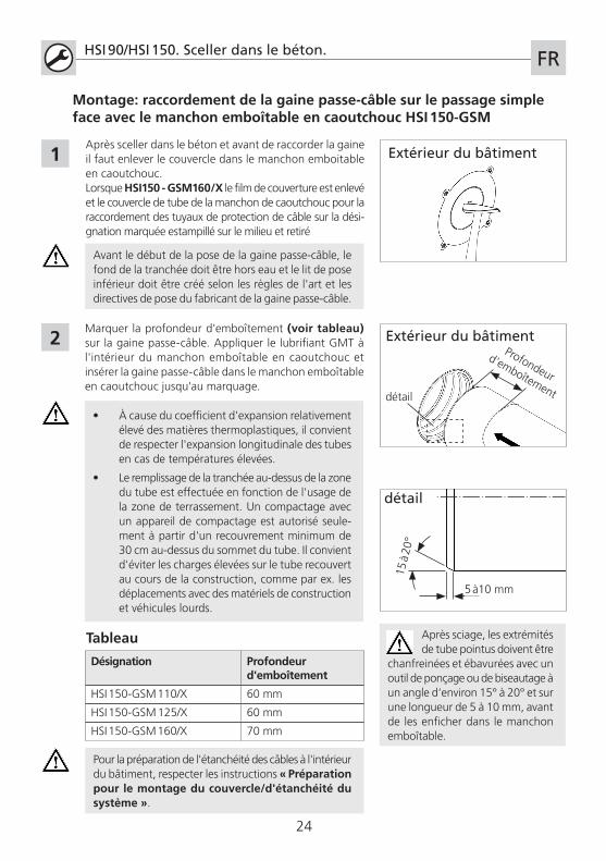
Marquer la profondeur d'emboîtement (voir tableau) sur la gaine passe-câble. Appliquer le lubrifiant GMT � l'intérieur du manchon emboîtable en caoutchouc et insérer la gaine passe-câble dans le manchon emboîtable en caoutchouc jusqu'au marquage.
Désignation Profondeur d'emboîtement
HSI 150-GSM 110/X 60 mm
HSI 150-GSM 125/X 60 mm
HSI 150-GSM 160/X 70 mm
Tableau
2
Apr�s sceller dans le béton et avant de raccorder la gaine il faut enlever le couvercle dans le manchon emboitable en caoutchouc.Lorsque HSI150 - GSM160/X le film de couverture est enlevé et le couvercle de tube de la manchon de caoutchouc pour la raccordement des tuyaux de protection de câble sur la dési-gnation marquée estampillé sur le milieu et retiré
1
Pour la préparation de l'étanchéité des câbles � l'intérieur du bâtiment, respecter les instructions « Préparation pour le montage du couvercle/d'étanchéité du système ».
Montage: raccordement de la gaine passe-câble sur le passage simple face avec le manchon emboîtable en caoutchouc HSI 150-GSM
Extérieur du bâtiment
Extérieur du bâtimentProfondeur
d'emboîtement
Avant le début de la pose de la gaine passe-câble, le fond de la tranchée doit �tre hors eau et le lit de pose inférieur doit �tre créé selon les r�gles de l'art et les directives de pose du fabricant de la gaine passe-câble.
• � cause du coefficient d'expansion relativement élevé des mati�res thermoplastiques, il convient de respecter l'expansion longitudinale des tubes en cas de températures élevées.
• Le remplissage de la tranchée au-dessus de la zone du tube est effectuée en fonction de l'usage de la zone de terrassement. Un compactage avec un appareil de compactage est autorisé seule-ment � partir d'un recouvrement minimum de 30 cm au-dessus du sommet du tube. Il convient d'éviter les charges élevées sur le tube recouvert au cours de la construction, comme par ex. les déplacements avec des matériels de construction et véhicules lourds.
Apr�s sciage, les extrémités de tube pointus doivent �tre
chanfreinées et ébavurées avec un outil de ponçage ou de biseautage � un angle d‘environ 15° � 20° et sur une longueur de 5 � 10 mm, avant de les enficher dans le manchon emboîtable.
détail
5 �10 mm
15 �
20°
détail
25
HSI 90/HSI 150. Sceller dans le béton. FR
Conformément � l‘usage prévu, nos produits sont conçus exclusivement pour �tre intégrés dans des constructions dont les matériaux sont conformes � la réglementation technique en vigueur. Nous déclinons toutes responsabilités dans le cas d‘une utilisation non-conforme pour l’usage indiqué si nous n‘avons pas donné notre accord par écrit apr�s consultation.
Sous réserve de modifications.Téléphone SAV +49 7322 1333-0
2
1
• Ouvrir le couvercle de fermeture du passage étanche seulement juste avant la pose des câbles. Respecter les instructions de montage du couvercle.
• Les passe-câbles inutilisés peuvent servir de passe-câbles de réserve étanches � la pression si la marque de qualité Hauff sur le couvercle n'est pas endommagée.
• Ne pas monter le couvercle � coup de marteau ou � l'aide d'un outil tranchant!
• Poser des nouveaux couvercles HSI 150-D resp. HSI90 sur les passe-câbles ouverts utilisés comme passages de réserve ou sur les couvercles qui ont été ouverts par mégarde.
• Ne pas réutiliser les couvercles démontés ou endommagés!
Montage: préparation pour le montage du couvercle/d'étanchéité du système
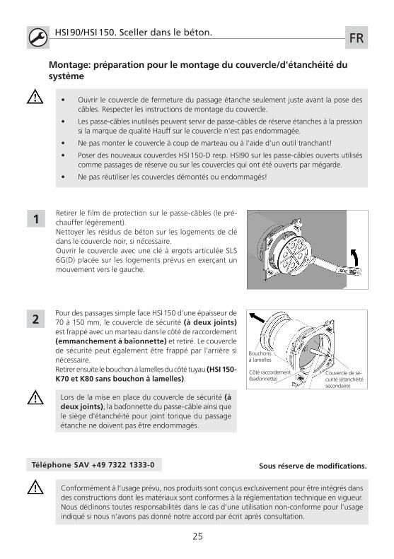
Retirer le film de protection sur le passe-câbles (le pré-chauffer lég�rement).Nettoyer les résidus de béton sur les logements de clé dans le couvercle noir, si nécessaire.Ouvrir le couvercle avec une clé � ergots articulée SLS 6G(D) placée sur les logements prévus en exerçant un mouvement vers le gauche.
Pour des passages simple face HSI 150 d'une épaisseur de 70 � 150 mm, le couvercle de sécurité (à deux joints) est frappé avec un marteau dans le côté de raccordement (emmanchement à baïonnette) et retiré. Le couvercle de sécurité peut également �tre frappé par l'arri�re si nécessaire.Retirer ensuite le bouchon � lamelles du côté tuyau (HSI 150-K70 et K80 sans bouchon à lamelles).
Côté raccordement(baïonnette)
Couvercle de sé-curité (étanchéité secondaire)
Bouchons � lamelles
Lors de la mise en place du couvercle de sécurité (à deux joints), la baïonnette du passe-câble ainsi que le si�ge d'étanchéité pour joint torique du passage étanche ne doivent pas �tre endommagés.
26
HSI 90/HSI 150. Inbedden in beton gaat als volgt.NL
• Principieel dienen de landelijk geldende voorschriften voor het verleggen en vullen van leidingen in acht te worden genomen.
• De ondergrond en de kabelonderbouw voor het verleggen van buizen en kabels zorgvuldig verdichten, zodat de kabels niet kunnen verzakken.
• Het verkeerd verleggen van kabels of kabelbeschermingsbuizen en het ondeskundig opvullen van kabelgoten veroorzaakt verzakkingen en kan daardoor leiden tot beschadi-gingen en lekkages.
• De doorvoer mag niet mechanisch worden belast door kabels of buizen.
• Voor het reinigen van de kabeldoorgangen mogen geen reinigingsmiddelen met oplos-middelen worden gebruikt, wij adviseren kabelreiniger KR M.T.X.
• Bij bundeling van buisaansluitingen �a = 160mm verdient het gebruik van afstandhouder HSI-AH 40 aanbeveling voor een optimale verdichting van het beton en de verdichting in de kabelgoot (asmaatuitbreiding van 210 mm naar 250 mm).
• Andere toebehoren en informatie onder www.hauff-technik.de en in de technische specificatiebladen.
Inhoud
1 Algemene informatie en beoogd gebruik2 Algemene aanwijzingen/veiligheidsinstructies3 Beschrijving4 Leveringsomvang5 Benodigd gereedschap en hulpmiddelen6 Montage
1 Algemene informatie en beoogd gebruik
Systeemoplossingsstandaard voor kabelafdichtingen.
2 Algemene aanwijzingen
• Bij beschermingsbuisaansluitingen wordt de veiligheid van het systeem voor de kabel-doorvoer beperkt tot de dichtheid van het beschermingsbuissysteem, voor zover een kabelafdichting wordt uitgevoerd.
• Bescherm de dichtpakking bij de montage-installatie tegen beschadigingen, vocht en verontreinigingen. Controleer de levering op volledigheid en alle losse onderdelen en op eventuele schade
• Er mogen alleen onbeschadigde delen worden gemonteerd.
• Bij de installatie moeten de geldende voorschriften van de beroepsvereniging, de VDE-bepalingen, de geldende nationale veiligheids- en ongevallenpreventievoorschriften en de richtlijnen (werk- en procedure-instructies) van uw onderneming worden aangehouden.
Veiligheidsinstructies
27
3 Beschrijving: enkelvoudige dichtpakking HSI 90/HSI 150-K/X
HSI 90/HSI 150. Inbedden in beton gaat als volgt.NL
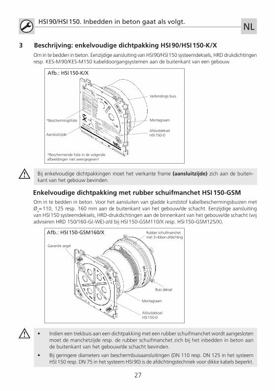
Om in te bedden in beton. Eenzijdige aansluiting van HSI 90/HSI 150 systeemdeksels, HRD drukdichtingen resp. KES-M 90/KES-M150 kabeldoorgangsystemen aan de buitenkant van een gebouw.
Montagraam
AfsluitdekselHSI 150-D
Verbindings buis
Aansluitzijde
Afb.: HSI 150-K/X
*Beschermingsfolie
*Beschermende folie in de volgende afbeeldingen niet weergegeven!
Bij enkelvoudige dichtpakkingen moet het vierkante frame (aansluitzijde) zich aan de buiten-kant van het gebouw bevinden.
Enkelvoudige dichtpakking met rubber schuifmanchet HSI 150-GSMOm in te bedden in beton. Voor het aansluiten van gladde kunststof kabelbeschermingsbuizen met �a= 110, 125 resp. 160 mm aan de buitenkant van het gebouw/de schacht. Eenzijdige aansluiting van HSI 150 systeemdeksels, HRD-drukdichtingen aan de binnenkant van het gebouw/de schacht (wij adviseren HRD 150/160-G(-WE)-z/d bij HSI 150-GSM110/X resp. HSI 150-GSM125/X).
• Indien een trekbuis aan een dichtpakking met een rubber schuifmanchet wordt aangesloten moet de manchetzijde resp. de rubber schuifmanchet zich bij het inbedden in beton aan de buitenkant van het gebouw/de schacht bevinden.
• Bij geringere diameters van beschermbuisaansluitingen (DN 110 resp. DN 125 in het systeem HSI 150 resp. DN 75 in het systeem HSI 90) is de afdichtingstechniek voor dikke kabels beperkt.
Montagraam
AfsluitdekselHSI 150-D
Garantie zegel
Rubber schuifmanchet met 3-ribben-afdichting
Afb.: HSI 150-GSM160/X
+49 7322 1333
-0
Buis deksel
28
Dubbele dichtpakking HSI 90/HSI 150-K2/X
HSI 90/HSI 150. Inbedden in beton gaat als volgt.NL
Montagraam
AfsluitdekselHSI 150-D
Garantie zegel
Tussenbuis
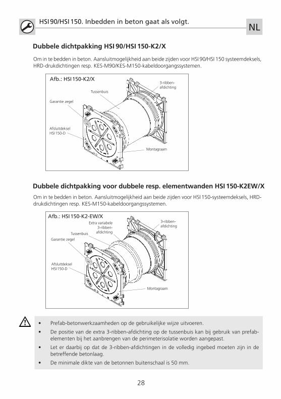
Om in te bedden in beton. Aansluitmogelijkheid aan beide zijden voor HSI 90/HSI 150 systeemdeksels, HRD-drukdichtingen resp. KES-M90/KES-M150-kabeldoorgangssystemen.
3-ribben-afdichting
+49 7322 1333
-0
Dubbele dichtpakking voor dubbele resp. elementwanden HSI 150-K2EW/X
Om in te bedden in beton. Aansluitmogelijkheid aan beide zijden voor HSI 150-systeemdeksels, HRD-drukdichtingen resp. KES-M150-kabeldoorgangssystemen.
• Prefab-betonwerkzaamheden op de gebruikelijke wijze uitvoeren.
• De positie van de extra 3-ribben-afdichting op de tussenbuis kan bij gebruik van prefab-elementen bij het aanbrengen van de perimeterisolatie worden aangepast.
• Let er daarbij op dat de 3-ribben-afdichtingen in de volledig ingebed moeten zijn in de betreffende betonlaag.
• De minimale dikte van de betonnen buitenschaal is 50 mm.
Montagraam
AfsluitdekselHSI 150-D
Garantie zegel
Extra variabele 3-ribben-afdichting
3-ribben-afdichting
Afb.: HSI 150-K2/X
Afb.: HSI 150-K2-EW/X
+49 7322 1333
-0
Tussenbuis
29
HSI 90/HSI 150. Inbedden in beton gaat als volgt.NL
5 Benodigd gereedschap en hulpmiddelen
Voor de correcte installatie van de HSI 90 en HSI 150-dichtpakkingen hebt u naast het standaard ge-reedschap de volgende gereedschappen en hulpmiddelen nodig:
1 momentsleutel SLS 6G resp. SLS 6GD (voor muren met perimeterisolatie)
Toebehoren:
Afstandhouder HSI-AH40 (VPE 2 St.)
Hulpmiddelen:
Glijmiddel GMT (Artikelnummer: 2790009100) voor HSI 150-GSM
4 Leveringsomvang
Bij levering van de HSI-dichtpakkingen is inbegrepen:
Enkelvoudige dichtpakking HSI 90/HSI 150-K/X
1 montageframe incl. beschermende folie met een 3-ribben-afdichting 1 afsluitdeksels 1 Garantie zegel 1 verbindings buis met veiligheidsdeksel bij enkelvoudige dichtpakkingen HSI 150 voor wanddikte 70-150 mm 1 lamellenstop (bij enkelvoudige dichtpakkingen HSI 150 vanaf een wanddikte van > 80 mm)
Enkelvoudige dichtpakking met rubber schuifmanchet HSI 150-GSM
1 montageframe incl. beschermende folie met een 3-ribben-afdichting 1 afsluitdeksels 1 Garantie zegel 1 rubber schuifmanchet met 3-ribben-afdichting 1 spanband bij HSI 150-GSM 160/X 1 Buis deksel met aanwijzingssticker
Dubbele dichtpakking HSI 90/HSI 150-K2/X
2 montageframes incl. beschermende folie, elk met een 3-ribben-afdichting 2 afsluitdeksels 2 Garantie zegel 1 verbindings buis bij HSI150
Dubbele dichtpakking voor dubbele resp. elementwanden HSI 150-K2EW/X
2 montageframes incl. beschermende folie, elk met een3-ribben-afdichting en beschermende folie 2 afsluitdeksels 2 Garantie zegel 1 verbindings buis bij HSI150 met extra 3-ribben-afdichting
1
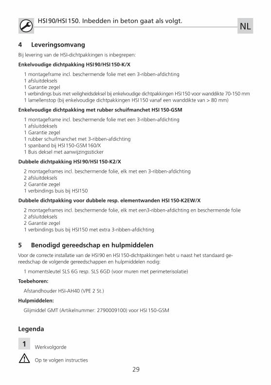
Legenda
Werkvolgorde
Op te volgen instructies
30
Asa
fsta
nd25
0 m
m
Ran
dafs
tand
65 m
m
HSI 90/HSI 150. Inbedden in beton gaat als volgt. NL
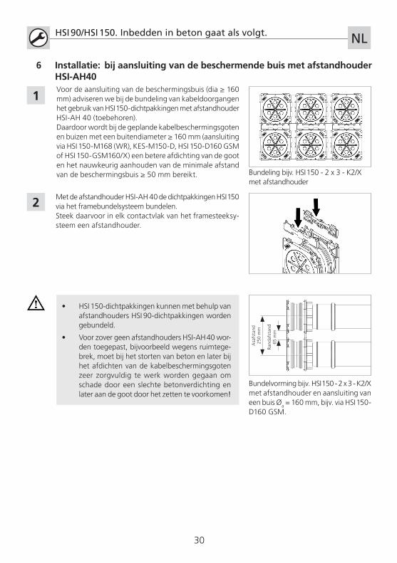
Voor de aansluiting van de beschermingsbuis (dia ≥ 160 mm) adviseren we bij de bundeling van kabeldoorgangen het gebruik van HSI 150-dichtpakkingen met afstandhouder HSI-AH 40 (toebehoren).Daardoor wordt bij de geplande kabelbeschermingsgoten en buizen met een buitendiameter ≥ 160 mm (aansluiting via HSI 150-M168 (WR), KES-M150-D, HSI 150-D160 GSM of HSI 150-GSM160/X) een betere afdichting van de goot en het nauwkeurig aanhouden van de minimale afstand van de beschermingsbuis ≥ 50 mm bereikt.
2
• HSI 150-dichtpakkingen kunnen met behulp van afstandhouders HSI 90-dichtpakkingen worden gebundeld.
• Voor zover geen afstandhouders HSI-AH 40 wor-den toegepast, bijvoorbeeld wegens ruimtege-brek, moet bij het storten van beton en later bij het afdichten van de kabelbeschermingsgoten zeer zorgvuldig te werk worden gegaan om schade door een slechte betonverdichting en later aan de goot door het zetten te voorkomen!
Met de afstandhouder HSI-AH 40 de dichtpakkingen HSI 150 via het framebundelsysteem bundelen. Steek daarvoor in elk contactvlak van het framesteeksy-steem een afstandhouder.
Bundelvorming bijv. HSI 150 - 2 x 3 - K2/X met afstandhouder en aansluiting van een buis �a = 160 mm, bijv. via HSI 150-D160 GSM.
1
6 Installatie: bij aansluiting van de beschermende buis met afstandhouder HSI-AH40
Bundeling bijv. HSI 150 - 2 x 3 - K2/X met afstandhouder
31
Bekistingsafstand
niet kleiner dan
Wanddikte „X“
HSI 90/HSI 150. Inbedden in beton gaat als volgt.NL
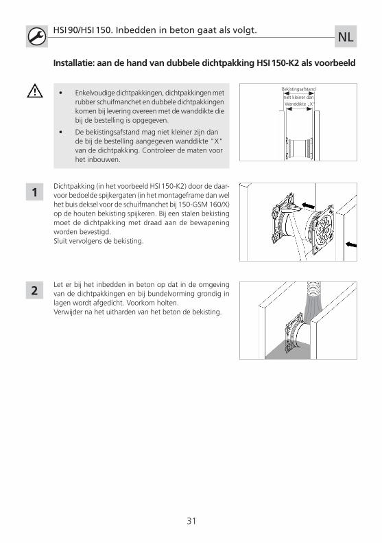
Dichtpakking (in het voorbeeld HSI 150-K2) door de daar-voor bedoelde spijkergaten (in het montageframe dan wel het buis deksel voor de schuifmanchet bij 150-GSM 160/X) op de houten bekisting spijkeren. Bij een stalen bekisting moet de dichtpakking met draad aan de bewapening worden bevestigd. Sluit vervolgens de bekisting.
1
2Let er bij het inbedden in beton op dat in de omgeving van de dichtpakkingen en bij bundelvorming grondig in lagen wordt afgedicht. Voorkom holten. Verwijder na het uitharden van het beton de bekisting.
Installatie: aan de hand van dubbele dichtpakking HSI 150-K2 als voorbeeld
• Enkelvoudige dichtpakkingen, dichtpakkingen met rubber schuifmanchet en dubbele dichtpakkingen komen bij levering overeen met de wanddikte die bij de bestelling is opgegeven.
• De bekistingsafstand mag niet kleiner zijn dan de bij de bestelling aangegeven wanddikte "X" van de dichtpakking. Controleer de maten voor het inbouwen.
32
HSI 90/HSI 150. Inbedden in beton gaat als volgt. NL
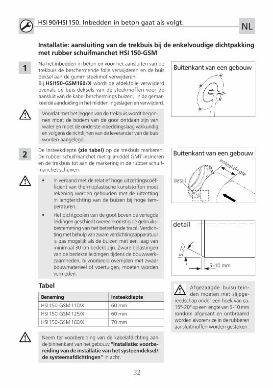
De insteekdiepte (zie tabel) op de trekbuis markeren. De rubber schuifmanchet met glijmiddel GMT insmeren en de trekbuis tot aan de markering in de rubber schuif-manchet schuiven.
Benaming Insteekdiepte
HSI 150-GSM 110/X 60 mm
HSI 150-GSM 125/X 60 mm
HSI 150-GSM 160/X 70 mm
Tabel
2
Na het inbedden in beton en voor het aansluiten van de trekbuis de beschermende folie verwijderen en de buis deksel aan de gummisteekmof verwijderen.Bij HSI150-GSM160/X wordt de afdekfolie verwijderd evenals de buis deksels van de steekmoffen voor de aansluit van de kabel beschermings buizen, in de gemar-keerde aanduiding in het midden ingeslagen en verwijderd.
1
Neem ter voorbereiding van de kabelafdichting aan de binnenkant van het gebouw "Installatie: voorbe-reiding van de installatie van het systeemdeksel/de systeemafdichtingen" in acht.
Installatie: aansluiting van de trekbuis bij de enkelvoudige dichtpakking met rubber schuifmanchet HSI 150-GSM
Buitenkant van een gebouw
Buitenkant van een gebouwInsteekdiepte
Voordat met het leggen van de trekbuis wordt begon-nen moet de bodem van de goot ontdaan zijn van water en moet de onderste inbeddingslaag vakkundig en volgens de richtlijnen van de leverancier van de buis worden aangelegd.
• In verband met de relatief hoge uitzettingscoëf-ficiënt van thermoplastische kunststoffen moet rekening worden gehouden met de uitzetting in lengterichting van de buizen bij hoge tem-peraturen.
• Het dichtgooien van de goot boven de verlegde leidingen geschiedt overeenkomstig de gebruiks-bestemming van het betreffende tracé. Verdich-ting met behulp van zware verdichtingsapparatuur is pas mogelijk als de buizen met een laag van minimaal 30 cm bedekt zijn. Zware belastingen van de bedekte leidingen tijdens de bouwwerk-zaamheden, bijvoorbeeld overrijden met zwaar bouwmaterieel of voertuigen, moeten worden vermeden.
Afgezaagde buisuitein-den moeten met slijpge-
reedschap onder een hoek van ca. 15°- 20° op een lengte van 5 -10 mm rondom afgekant en ontbraamd worden alvorens ze in de rubberen aansluitmoffen worden gestoken.
detail
5 -10 mm
15 -2
0°detail

33
HSI 90/HSI 150. Inbedden in beton gaat als volgt.NL
Onze producten zijn uitsluitend bedoeld voor gebruik conform inbouw in bouwwerken ontwik-keld, waarvan de materialen aan de huidige stand van de techniek voldoen.Voor een andere toepassing dan wel ander gebruik, voor zover dit na overleg met ons niet uitdrukkelijk schrifte-lijk is bevestigd, aanvaarden wij geen aansprakelijkheid.
Wijzigingen voorbehouden.Servicetelefoon +49 (0) 7322 1333-0
2
1
• Het afsluitdeksel van de dichtpakking pas vlak voor het leggen van de kabel openen. Volg de montage-instructie voor het systeemdeksel.
• Niet benodigde kabeldoorgangen kunnen bij onbeschadigd Hauff-kwaliteitszegel op het afsluitdeksel als drukvaste reservedoorvoeren worden gebruikt.
• Afsluitdeksel niet met een hamer of een scherp object inslaan!
• Geopende kabeldoorgangen die als reservedoorvoeren moeten worden gebruikt resp. afsluitdeksels die per ongeluk zijn geopend moeten van nieuwe afsluitdeksels HSI 150-D resp. HSI90 worden voorzien!
• Gedemonteerde resp. beschadigde deksels mogen niet worden hergebruikt!
Installatie: voorbereiding van de installatie van het systeemdeksel/de systeemafdichting
Beschermende folie van de dichtpakking verwijderen (eerst licht verwarmen).Indien nodig betonresten uit de sleutelgaten in het zwar-te afsluitdeksel verwijderen.Deksel met de sleutel SLS 6G(D) via de sleutelgaten met een draaibeweging naar links openen.
Bij enkelvoudige dichtpakkingen HSI 150 met wanddikte 70 tot 150 mm wordt het veiligheidsdeksel (tweede afdichting) aan de aansluitzijde (bajonetaansluiting) met een hamer ingetikt en verwijderd. Optioneel kan het veiligheidsdeksel ook vanaf de achterzijde worden inges-lagen.Aansluitend wordt de lamellenstop aan de zijde van de buis verwijderd (HSI 150-K70 en -K80 hebben geen lamellenstop).
Aansluitzijde(bajonet)
Veiligheidsdeksel (tweede afdichting)
Lamellen-stop
Bij het intikken van het veiligheidsdeksel (tweede afdichting) mag de bajonetaansluiting en de dichtin-gshouder voor de O-ring van de dichtpakking niet worden beschadigd.
34
HSI 90/HSI 150. Prawidłowy sposób zabetonowania.PL
• Należy postępować zgodnie z obowiązującymi na szczeblu krajowym przepisami w zakresie układania rur oraz wypełniania pustek.
• Przed przystąpieniem do układania kabli/rur należy odpowiednio wzmocnić podłoże i konstrukcję wsporczą, aby zapobiec zapadaniu się układanych elementów.
• Nieprawidłowe układanie kabli lub rur osłonowych oraz niewłaściwe wypełnienie rowu kablowego powoduje zapadanie, które może doprowadzić do uszkodzeń układanych elementów i nieszczelności.
• Przepust nie powinien być obciążany mechanicznie przez kable bądź rury.
• Do czyszczenia przepustów kablowych nie wolno używać środków czyszczących zawierających rozpuszczalniki; zalecamy preparat do czyszczenia kabli KR M.T.X.
• W przypadku tworzenia pakietów złączy rurowych �a = 160 mm zalecamy zastosowanie przekładki HSI-AH 40 do optymalnego zagęszczenia betonu, a później uszczelnienie rowu kablowego (powiększenie odległości między osiami z 210 mm do 250 mm).
• Opis pozostałych elementów wyposażenia dodatkowego oraz szczegółowe informacje podane są na stronie internetowej www.hauff-technik.de oraz w arkuszach danych technicznych.
Spis treści
1 Informacje ogólne i przeznaczenie2 Wskazówki ogólne/instrukcje bezpieczeństwa3 Opis4 Zakres dostawy5 Niezbędne narzędzia i środki pomocnicze6 Montaż
1 Informacje ogólne i przeznaczenie
Standardowe rozwiązanie systemowe do uszczelnień kablowych.
2 Wskazówki ogólne
• W przypadku podłączeń rur osłonowych bezpieczeństwo systemu przepustu kablowego jest zapewniane tylko przez prawidłową szczelność systemu rur osłonowych, o ile nie jest wykonywane uszczelnienie kabli.
• Podczas montażu przepust kablowy należy chronić przed uszkodzeniami, wilgocią i za-nieczyszczeniami. Sprawdzić, czy dostawa jest kompletna oraz czy poszczególne części nie są uszkodzone
• Dozwolony jest montaż wyłącznie nieuszkodzonych części.
• Podczas instalacji należy stosować się do przepisów wydanych przez stowarzyszenia za-wodowe, niemieckie stowarzyszenie elektrotechniczne (VDE), odpowiednich krajowych przepisów BHP oraz wytycznych firmy (dotyczących przebiegu prac i procedur postępowania).
Instrukcja bezpieczeństwa
35
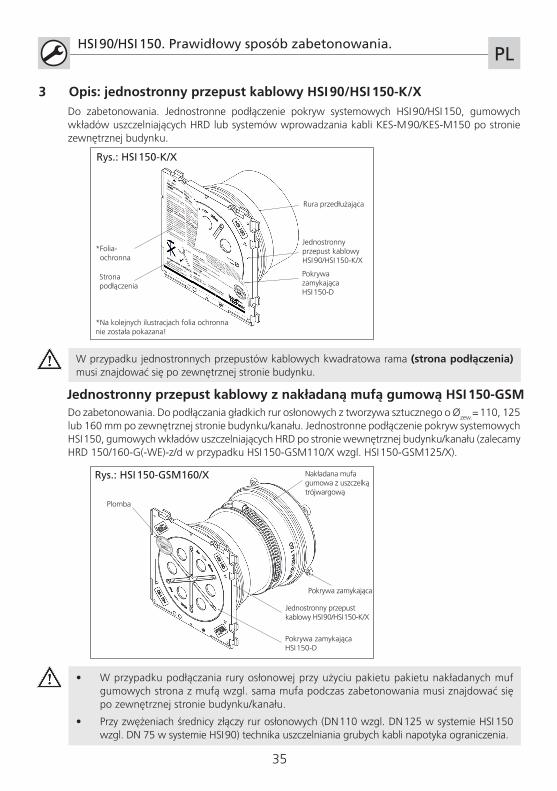
3 Opis: jednostronny przepust kablowy HSI 90/HSI 150-K/X
HSI 90/HSI 150. Prawidłowy sposób zabetonowania.PL
Do zabetonowania. Jednostronne podłączenie pokryw systemowych HSI 90/HSI 150, gumowych wkładów uszczelniających HRD lub systemów wprowadzania kabli KES-M 90/KES-M150 po stronie zewnętrznej budynku.
Jednostronny przepust kablowyHSI 90/HSI 150-K/X
Pokrywa zamykającaHSI 150-D
Rura przedłużająca
Strona podłączenia
Rys.: HSI 150-K/X
*Folia- ochronna
*Na kolejnych ilustracjach folia ochronna nie została pokazana!
W przypadku jednostronnych przepustów kablowych kwadratowa rama (strona podłączenia) musi znajdować się po zewnętrznej stronie budynku.
Jednostronny przepust kablowy z nakładaną mufą gumową HSI 150-GSMDo zabetonowania. Do podłączania gładkich rur osłonowych z tworzywa sztucznego o �zew.= 110, 125 lub 160 mm po zewnętrznej stronie budynku/kanału. Jednostronne podłączenie pokryw systemowych HSI 150, gumowych wkładów uszczelniających HRD po stronie wewnętrznej budynku/kanału (zalecamy HRD 150/160-G(-WE)-z/d w przypadku HSI 150-GSM110/X wzgl. HSI 150-GSM125/X).
• W przypadku podłączania rury osłonowej przy użyciu pakietu pakietu nakładanych muf gumowych strona z mufą wzgl. sama mufa podczas zabetonowania musi znajdować się po zewnętrznej stronie budynku/kanału.
• Przy zwężeniach średnicy złączy rur osłonowych (DN 110 wzgl. DN 125 w systemie HSI 150 wzgl. DN 75 w systemie HSI 90) technika uszczelniania grubych kabli napotyka ograniczenia.
Jednostronny przepust kablowy HSI 90/HSI 150-K/X
Pokrywa zamykającaHSI 150-D
Plomba
Nakładana mufa gumowa z uszczelką trójwargową
Rys.: HSI 150-GSM160/X
+49 7322 1333
-0
Pokrywa zamykająca
36
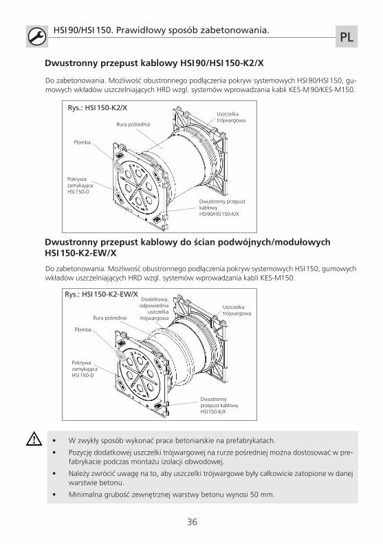
Dwustronny przepust kablowy HSI 90/HSI 150-K2/X
HSI 90/HSI 150. Prawidłowy sposób zabetonowania.PL
Dwustronny przepust kablowyHSI 90/HSI 150-K/X
Pokrywa zamykającaHSI 150-D
Plomba
Rura pośrednia
Do zabetonowania. Możliwość obustronnego podłączenia pokryw systemowych HSI 90/HSI 150, gu-mowych wkładów uszczelniających HRD wzgl. systemów wprowadzania kabli KES-M 90/KES-M150.
Uszczelka trójwargowa
+49 7322 1333
-0
Dwustronny przepust kablowy do ścian podwójnych/modułowych HSI 150-K2-EW/X
Do zabetonowania. Możliwość obustronnego podłączenia pokryw systemowych HSI 150, gumowych wkładów uszczelniających HRD wzgl. systemów wprowadzania kabli KES-M150.
• W zwykły sposób wykonać prace betoniarskie na prefabrykatach.
• Pozycję dodatkowej uszczelki trójwargowej na rurze pośredniej można dostosować w pre-fabrykacie podczas montażu izolacji obwodowej.
• Należy zwrócić uwagę na to, aby uszczelki trójwargowe były całkowicie zatopione w danej warstwie betonu.
• Minimalna grubość zewnętrznej warstwy betonu wynosi 50 mm.
Dwustronny przepust kablowyHSI 150-K/X
Pokrywa zamykającaHSI 150-D
Plomba
Dodatkowa, odpowiednia
uszczelka trójwargowa
Uszczelka trójwargowa
Rys.: HSI 150-K2/X
Rys.: HSI 150-K2-EW/X
+49 7322 1333
-0
Rura pośrednia
37
HSI 90/HSI 150. Prawidłowy sposób zabetonowania.PL
Dwustronny przepust kablowy do ścian podwójnych/modułowych HSI 150-K2-EW/X
5 Niezbędne narzędzia i środki pomocnicze
Do prawidłowego montażu przepustów kablowych HSI 90 i HSI 150 potrzebne są, oprócz standardowych narzędzi, następujące narzędzia i środki pomocnicze:
1 przegubowy klucz widełkowy SLS 6G lub SLS 6GD (do ścian z izolacją obwodową)
Akcesoria
Rozpórka HSI-AH40 (opakowanie jednostkowe 2 szt.)
Środki pomocnicze:
Środek poślizgowy GMT (Numer artykułu: 2790009100) do HSI 150-GSM
4 Zakres dostawy
Zakres dostawy przepustów kablowych HSI obejmuje:
Jednostronny przepust kablowy HSI 90/HSI 150-K/X
1 rama montażowa z folią ochronną i uszczelką trójwargową 1 pokrywa zamykająca 1 plomba 1 rura przedłużająca z pokrywą zabezpieczającą w przypadku jednostronnych przepustów kablowych HSI 150 do ścian o grubości 70-150 mm 1 zaślepka z wyżłobieniami (w przypadku jednostronnych przepustów kablowych HSI 150 do ścian o grubości > 80 mm)
Jednostronny przepust kablowy z nakładaną mufą gumową HSI 150-GSM
1 rama montażowa z folią ochronną i uszczelką trójwargową 1 pokrywa zamykająca 1 plomba 1 nakładana mufa gumowa z uszczelką trójwargową 1 taśma zaciskowa w przypadku HSI 150-GSM 160/X 1 zaślepka mufy z naklejką informacyjną
Dwustronny przepust kablowy HSI 90/HSI 150-K2/X
2 ramy montażowe z folią ochronną i uszczelką trójwargową 2 pokrywy zamykające 2 plomby 1 rura pośrednia dla HSI 150
Dwustronny przepust kablowy do ścian podwójnych/modułowych HSI 150-K2-EW/X
2 ramy montażowa z folią ochronną i uszczelką trójwargową 2 pokrywy zamykające 2 plomby 1 rura pośrednia dla HSI 150 z dodatkową uszczelką trójwargową
1
Legenda
Czynności
Ważne wskazówki
38
Rozs
taw
osi
250
mm
Od
stęp
od
kraw
ędzi
65 m
m
HSI 90/HSI 150. Prawidłowy sposób zabetonowania. PL
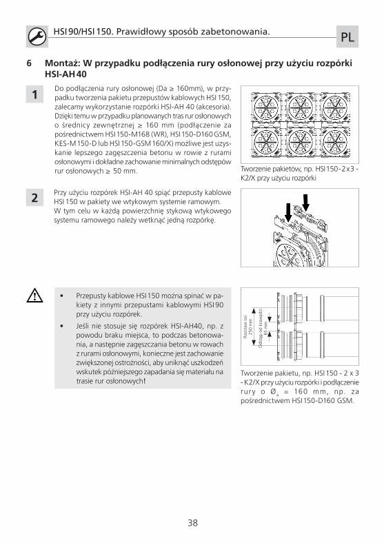
Do podłączenia rury osłonowej (Da ≥ 160mm), w przy-padku tworzenia pakietu przepustów kablowych HSI 150, zalecamy wykorzystanie rozpórki HSI-AH 40 (akcesoria).Dzięki temu w przypadku planowanych tras rur osłonowych o średnicy zewnętrznej ≥ 160 mm (podłączenie za pośrednictwem HSI 150-M168 (WR), HSI 150-D160 GSM, KES-M 150-D lub HSI 150-GSM 160/X) możliwe jest uzys-kanie lepszego zagęszczenia betonu w rowie z rurami osłonowymi i dokładne zachowanie minimalnych odstępów rur osłonowych ≥ 50 mm.
2
• Przepusty kablowe HSI 150 można spinać w pa-kiety z innymi przepustami kablowymi HSI 90 przy użyciu rozpórek.
• Jeśli nie stosuje się rozpórek HSI-AH40, np. z powodu braku miejsca, to podczas betonowa-nia, a następnie zagęszczania betonu w rowach z rurami osłonowymi, konieczne jest zachowanie zwiększonej ostrożności, aby uniknąć uszkodzeń wskutek późniejszego zapadania się materiału na trasie rur osłonowych!
Przy użyciu rozpórek HSI-AH 40 spiąć przepusty kablowe HSI 150 w pakiety we wtykowym systemie ramowym. W tym celu w każdą powierzchnię stykową wtykowego systemu ramowego należy wetknąć jedną rozpórkę.
Tworzenie pakietu, np. HSI 150 - 2 x 3 - K2/X przy użyciu rozpórki i podłączenie rur y o � a = 160 mm, np. za pośrednictwem HSI 150-D160 GSM.
1
6 Montaż: W przypadku podłączenia rury osłonowej przy użyciu rozpórki HSI-AH 40
Tworzenie pakietów, np. HSI 150 - 2 x 3 - K2/X przy użyciu rozpórki

39
Odstęp szalunku
nie mniejszy niż
grubość ściany „X”
HSI 90/HSI 150. Prawidłowy sposób zabetonowania.PL
Przybić przepust kablowy (w przykładzie HSI 150-K2) przez przeznaczone do tego otwory (w ramie montażowej oraz osłonę mufy nakładanej HSI 150-GSM 160/X) do szalunku drewnianego. W przypadku szalunku stalowego przepust kablowy należy przymocować drutem do zbrojenia. Następnie zamknąć szalunek.
1
2Podczas zabetonowywania należy pamiętać, aby zagęszczanie w obszarze przepustów kablowych i utwor-zonych pakietów przebiegało warstwami. Niepożądane jest tworzenie się jam usadowych. Po utwardzeniu się betonu należy usunąć szalunek.
Montaż: Na przykładzie dwustronnego przepustu kablowego HSI 150-K2
• Jednostronne przepusty kablowe, przepusty kablowe z nakładaną mufą gumową oraz dwus-tronne przepusty kablowe w dostarczonym stanie odpowiadają grubości ściany podanej podczas składania zamówienia.
• Odstęp szalunku nie może być mniejszy od po-danej podczas składania zamówienia grubości ściany „X” dla przepustu kablowego. Przed zamontowaniem należy skontrolować wymiary.
40
HSI 90/HSI 150. Prawidłowy sposób zabetonowania. PL
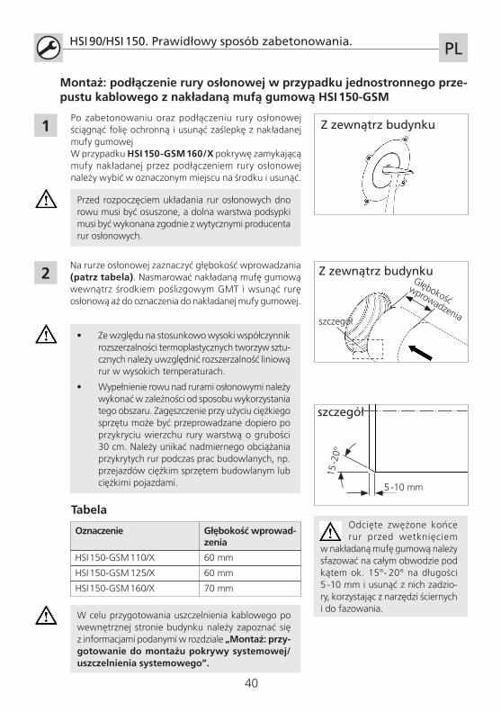
Na rurze osłonowej zaznaczyć głębokość wprowadzania (patrz tabela). Nasmarować nakładaną mufę gumową wewnątrz środkiem poślizgowym GMT i wsunąć rurę osłonową aż do oznaczenia do nakładanej mufy gumowej.
Oznaczenie Głębokość wprowad-zenia
HSI 150-GSM 110/X 60 mm
HSI 150-GSM 125/X 60 mm
HSI 150-GSM 160/X 70 mm
Tabela
2
Po zabetonowaniu oraz podłączeniu rury osłonowej ściągnąć folię ochronną i usunąć zaślepkę z nakładanej mufy gumowejW przypadku HSI 150-GSM 160/X pokrywę zamykającą mufy nakładanej przez podłączeniem rury osłonowej należy wybić w oznaczonym miejscu na środku i usunąć.
1
W celu przygotowania uszczelnienia kablowego po wewnętrznej stronie budynku należy zapoznać się z informacjami podanymi w rozdziale „Montaż: przy-gotowanie do montażu pokrywy systemowej/uszczelnienia systemowego”.
Montaż: podłączenie rury osłonowej w przypadku jednostronnego prze-pustu kablowego z nakładaną mufą gumową HSI 150-GSM
Z zewnątrz budynku
Z zewnątrz budynkuGłębokość
wprowadzenia
Przed rozpoczęciem układania rur osłonowych dno rowu musi być osuszone, a dolna warstwa podsypki musi być wykonana zgodnie z wytycznymi producenta rur osłonowych.
• Ze względu na stosunkowo wysoki współczynnik rozszerzalności termoplastycznych tworzyw sztu-cznych należy uwzględnić rozszerzalność liniową rur w wysokich temperaturach.
• Wypełnienie rowu nad rurami osłonowymi należy wykonać w zależności od sposobu wykorzystania tego obszaru. Zagęszczenie przy użyciu ciężkiego sprzętu może być przeprowadzane dopiero po przykryciu wierzchu rury warstwą o grubości 30 cm. Należy unikać nadmiernego obciążania przykrytych rur podczas prac budowlanych, np. przejazdów ciężkim sprzętem budowlanym lub ciężkimi pojazdami.
Odcięte zwężone końce rur przed wetknięciem
w nakładaną mufę gumową należy sfazować na całym obwodzie pod kątem ok. 15°- 20° na długości 5 -10 mm i usunąć z nich zadzio-ry, korzystając z narzędzi ściernych i do fazowania.
szczegół
5 -10 mm
15 -2
0°
szczegół
41
HSI 90/HSI 150. Prawidłowy sposób zabetonowania. PL
Nasze produkty, zgodnie z ich przeznaczeniem, zostały opracowane wyłącznie do montażu w budynkach wykonanych z materiałów budowlanych zgodnych z aktualnym stanem wiedzy technicznej. Nie ponosimy odpowiedzialności za wszelkie inne lub wykraczające poza wyżej opisane zastosowania, o ile nie zostały one przez nas w sposób wyraźny potwierdzone na piśmie.
Zastrzega się prawo do wprowadzania zmian.Telefon działu serwisowego: +49 7322 1333-0
2
1
• Pokrywę zamykającą przepust kablowy otwiera się bezpośrednio przed ułożeniem kabli. Przestrzegać instrukcji montażu pokrywy systemowej.
• Niewykorzystanych przepustów kablowych można użyć jako zapasowych przepustów hermetycznych, jeśli plomba Hauff na pokrywie zamykającej nie jest naruszona.
• Nie wbijać pokrywy zamykającej młotkiem ani innym przedmiotem o ostrych krawędziach!
• Otwarte przepusty kablowe przeznaczone do wykorzystania jako przepusty zapasowe bądź przepusty, z których przypadkowo zdjęto pokrywę zamykającą, należy wyposażyć w nowe pokrywy zamykające HSI 150 lub HSI 90!
• Zdemontowanych wzgl. uszkodzonych pokryw zamykających nie należy ponownie wykorzystywać!
Montaż: przygotowanie do montażu pokrywy systemowej/uszczelnienia systemowego
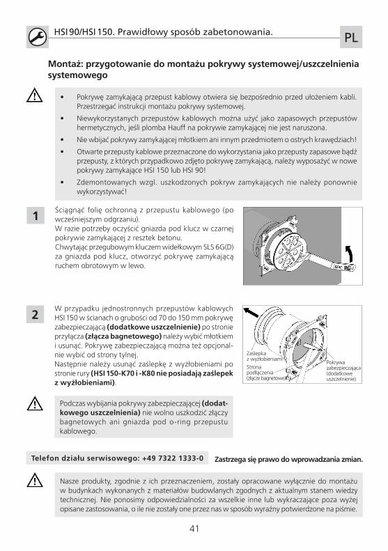
Ściągnąć folię ochronną z przepustu kablowego (po wcześniejszym odgrzaniu).W razie potrzeby oczyścić gniazda pod klucz w czarnej pokrywie zamykającej z resztek betonu.Chwytając przegubowym kluczem widełkowym SLS 6G(D) za gniazda pod klucz, otworzyć pokrywę zamykającą ruchem obrotowym w lewo.
W przypadku jednostronnych przepustów kablowych HSI 150 w ścianach o grubości od 70 do 150 mm pokrywę zabezpieczającą (dodatkowe uszczelnienie) po stronie przyłącza (złącza bagnetowego) należy wybić młotkiem i usunąć. Pokrywę zabezpieczającą można też opcjonal-nie wybić od strony tylnej.Następnie należy usunąć zaślepkę z wyżłobieniami po stronie rury (HSI 150-K70 i -K80 nie posiadają zaślepek z wyżłobieniami).
Strona podłączenia(złącze bagnetowe)
Pokrywa zabezpieczająca (dodatkowe uszczelnienie)
Zaślepka z wyżłobieniami
Podczas wybijania pokrywy zabezpieczającej (dodat-kowego uszczelnienia) nie wolno uszkodzić złączy bagnetowych ani gniazda pod o-ring przepustu kablowego.
42
Notizen / Notes / Remarques / Opmerkingen / Notatki

43
Notizen / Notes / Remarques / Opmerkingen / Notatki
Hauff-Technik GmbH & Co. KGRobert-Bosch-Straße 989568 Hermaringen, GERMANY
Tel. +49 7322 1333-0Fax +49 7322 1333-999
ma_
HSI
90_
150_
so_w
ird_e
inbe
toni
ert_
1512
0250
9003
2067