molded case circuit breakers
DESCRIPTION
MCCBTRANSCRIPT
LEARNING MODULE 8:MOLDED CASE CIRCUIT BREAKERS
101 B
ASIC
S SE
RIES
Cutler-Hammer
1
MOLDED CASE CIRCUIT BREAKERS
Welcome to Module 8, covering molded case circuit breakers. In previous modules,you have learned about the fundamentals of circuit breakers (Module 5), mediumvoltage power circuit breakers (Module 6), and low voltage power circuit breakers(Module 7, 7+). In this module, we will specifically cover molded case circuitbreakers (MCCBs): where they are used, their components and accessories.
This module is intended to be a continuation of the study of circuit breakers. Youshould have a good understanding of the concepts discussed in Module 5. Sincevarious terms and phrases will be used in this module without providing furtherexplanation, you might wish to review Module 5 before proceeding.
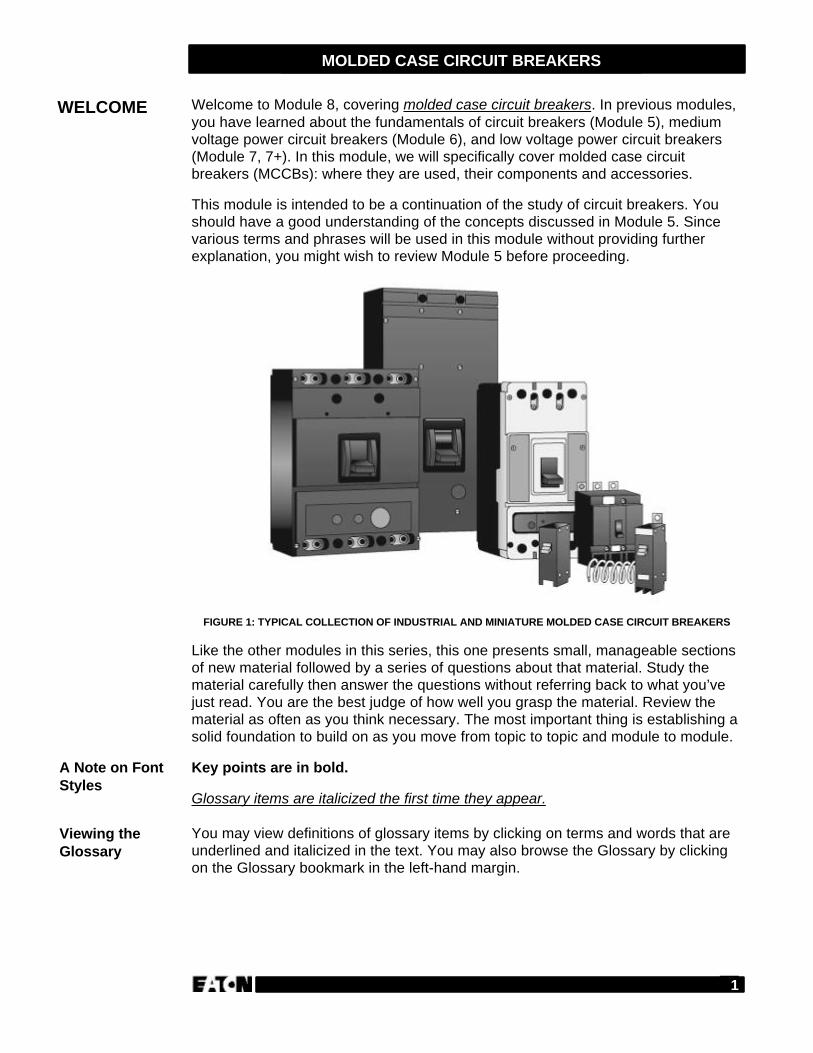
FIGURE 1: TYPICAL COLLECTION OF INDUSTRIAL AND MINIATURE MOLDED CASE CIRCUIT BREAKERS
Like the other modules in this series, this one presents small, manageable sectionsof new material followed by a series of questions about that material. Study thematerial carefully then answer the questions without referring back to what you’vejust read. You are the best judge of how well you grasp the material. Review thematerial as often as you think necessary. The most important thing is establishing asolid foundation to build on as you move from topic to topic and module to module.
Key points are in bold.
Glossary items are italicized the first time they appear.
You may view definitions of glossary items by clicking on terms and words that areunderlined and italicized in the text. You may also browse the Glossary by clickingon the Glossary bookmark in the left-hand margin.
WELCOME
A Note on FontStyles
Viewing theGlossary
2
MOLDED CASE CIRCUIT BREAKERS
We’ll step through each of these topics in detail:
Section Title Page Number
• Overview 3
• What Are Molded Case Circuit Breakers? 3
• Circuit Breaker Components 4
• Frame 4
• Operating Mechanism 5
• Arc Extinguisher 5
• Trip Unit 6
• Review 1 8
• Ratings and Environment 9
• Ratings 9
• Environment 10
• Review 2 12
• Motor Circuit Protectors 13
• Fuse vs. Circuit Breaker 13
• Components 14
• How It Operates 15
• Applications 16
• Review 3 17
• Accessories and Modifications 18
• Operational Devices 18
• Termination Devices 20
• Review 4 25
• Handle Operating Devices 26
• Lock and Interlock Devices 28
• Miscellaneous Devices 30
• Mounting and Enclosures 31
• Helping the Customer 33
• Protecting Non-Motor Circuits 33
• Protecting Motor Circuits 33
• Review 5 34
• Glossary 35
• Review Answers 37
WHAT YOUWILL LEARN
3
MOLDED CASE CIRCUIT BREAKERS
In Module 5, Fundamentals of Circuit Breakers, the definitions of a circuit breakerwere given as follows:
• NEMA Definition – A circuit breaker is defined in NEMA standards as a devicedesigned to open and close a circuit by non-automatic means, and to open thecircuit automatically on a predetermined overcurrent, without injury to itself whenproperly applied within its rating.
• ANSI Definition – A circuit breaker is defined in ANSI standards as a mechanicalswitching device, capable of making, carrying and breaking currents undernormal circuit conditions, and also making and carrying for a specified time andbreaking currents under specified abnormal circuit conditions such as those ofshort circuit.
The molded case circuit breaker is one of the two basic low voltage classes ofcircuit breakers. The other class is the low voltage power circuit breaker, which iscovered in modules 7 and 7+.
Molded case circuit breakers are tested and rated according to the UL 489Standard. Their current carrying parts, mechanisms and trip devices arecompletely contained within a molded case of insulating material. MCCBs areavailable in various frame sizes with various interrupting ratings for each frame size.
Molded case circuit breakers are designed to provide circuit protection for lowvoltage distribution systems. They protect connected devices against overloadsand/or short circuits. They are used primarily in panelboards and switchboardswhere they are fixed mounted. Some of the larger MCCBs are available in drawoutmount design.
Molded case circuit breakers are available with special features making themsuitable for the protection of motor circuits when used in conjunction with aseparate overload protection device. In these applications, they are often referred toas motor circuit protectors (MCPs).
OVERVIEW
What Are MoldedCase CircuitBreakers?
4
MOLDED CASE CIRCUIT BREAKERS
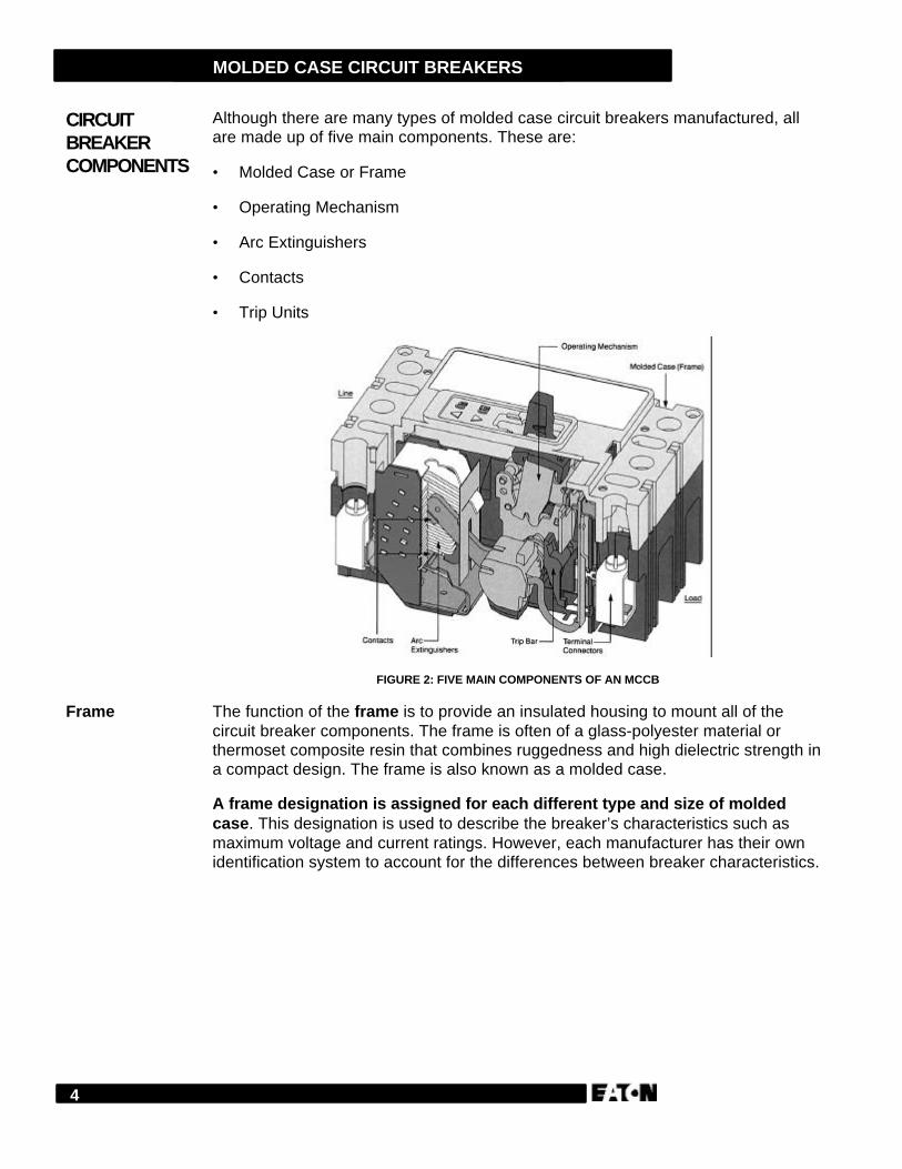
Although there are many types of molded case circuit breakers manufactured, allare made up of five main components. These are:
• Molded Case or Frame
• Operating Mechanism
• Arc Extinguishers
• Contacts
• Trip Units
FIGURE 2: FIVE MAIN COMPONENTS OF AN MCCB
The function of the frame is to provide an insulated housing to mount all of thecircuit breaker components. The frame is often of a glass-polyester material orthermoset composite resin that combines ruggedness and high dielectric strength ina compact design. The frame is also known as a molded case.
A frame designation is assigned for each different type and size of moldedcase. This designation is used to describe the breaker’s characteristics such asmaximum voltage and current ratings. However, each manufacturer has their ownidentification system to account for the differences between breaker characteristics.
CIRCUITBREAKERCOMPONENTS
Frame
5
MOLDED CASE CIRCUIT BREAKERS
The operating mechanism is the means to open and close the contacts. Thespeed with which the contacts open or close is independent of how fast the handleis moved. This is known as quick-make, quick-break. The breaker cannot beprevented from tripping by holding the handle in the ON position. This is known astrip-free. The handle position indicates the status of the contacts — closed, open ortripped. When the contacts are in the tripped position, the handle is in a midwayposition.
To restore service after the breaker trips, the handle must be moved first to theOFF position from its center tripped position. Then the handle must be moved tothe ON position. When breakers are mounted in a group, as in a panelboard, thedistinct handle position clearly indicates the faulted circuit. Some breaker designsalso incorporate a push-to-trip mechanism. This allows a manual means to trip thebreaker and test the mechanism.
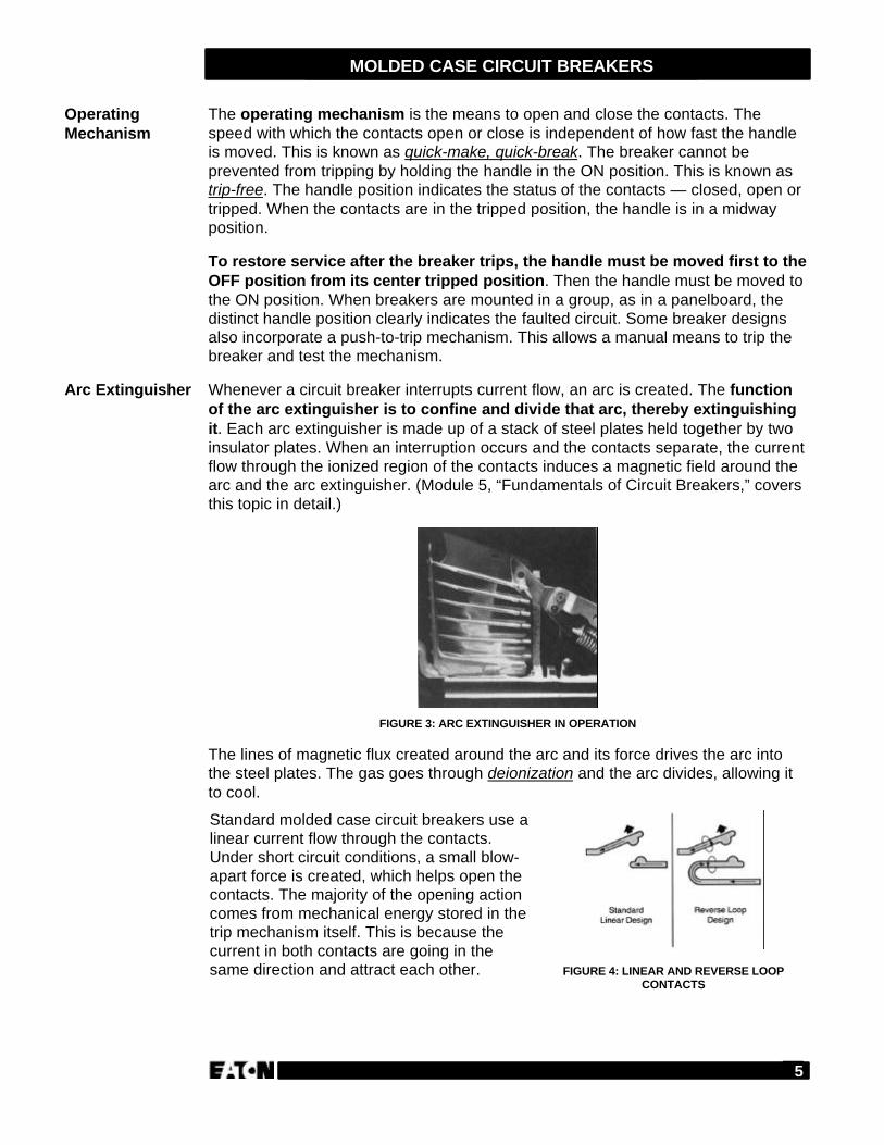
Whenever a circuit breaker interrupts current flow, an arc is created. The functionof the arc extinguisher is to confine and divide that arc, thereby extinguishingit. Each arc extinguisher is made up of a stack of steel plates held together by twoinsulator plates. When an interruption occurs and the contacts separate, the currentflow through the ionized region of the contacts induces a magnetic field around thearc and the arc extinguisher. (Module 5, “Fundamentals of Circuit Breakers,” coversthis topic in detail.)
FIGURE 3: ARC EXTINGUISHER IN OPERATION
The lines of magnetic flux created around the arc and its force drives the arc intothe steel plates. The gas goes through deionization and the arc divides, allowing itto cool.
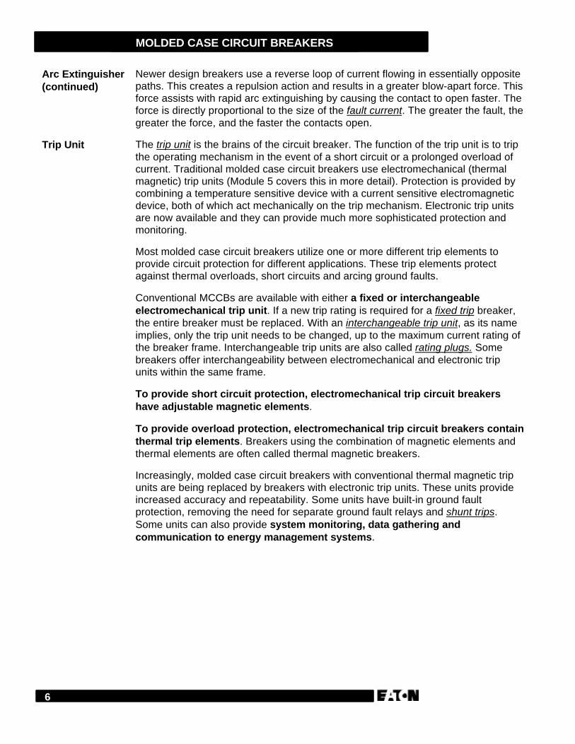
Standard molded case circuit breakers use alinear current flow through the contacts.Under short circuit conditions, a small blow-apart force is created, which helps open thecontacts. The majority of the opening actioncomes from mechanical energy stored in thetrip mechanism itself. This is because thecurrent in both contacts are going in thesame direction and attract each other. FIGURE 4: LINEAR AND REVERSE LOOP
CONTACTS
OperatingMechanism
Arc Extinguisher
6
MOLDED CASE CIRCUIT BREAKERS
Newer design breakers use a reverse loop of current flowing in essentially oppositepaths. This creates a repulsion action and results in a greater blow-apart force. Thisforce assists with rapid arc extinguishing by causing the contact to open faster. Theforce is directly proportional to the size of the fault current. The greater the fault, thegreater the force, and the faster the contacts open.
The trip unit is the brains of the circuit breaker. The function of the trip unit is to tripthe operating mechanism in the event of a short circuit or a prolonged overload ofcurrent. Traditional molded case circuit breakers use electromechanical (thermalmagnetic) trip units (Module 5 covers this in more detail). Protection is provided bycombining a temperature sensitive device with a current sensitive electromagneticdevice, both of which act mechanically on the trip mechanism. Electronic trip unitsare now available and they can provide much more sophisticated protection andmonitoring.
Most molded case circuit breakers utilize one or more different trip elements toprovide circuit protection for different applications. These trip elements protectagainst thermal overloads, short circuits and arcing ground faults.
Conventional MCCBs are available with either a fixed or interchangeableelectromechanical trip unit. If a new trip rating is required for a fixed trip breaker,the entire breaker must be replaced. With an interchangeable trip unit, as its nameimplies, only the trip unit needs to be changed, up to the maximum current rating ofthe breaker frame. Interchangeable trip units are also called rating plugs. Somebreakers offer interchangeability between electromechanical and electronic tripunits within the same frame.
To provide short circuit protection, electromechanical trip circuit breakershave adjustable magnetic elements.
To provide overload protection, electromechanical trip circuit breakers containthermal trip elements. Breakers using the combination of magnetic elements andthermal elements are often called thermal magnetic breakers.
Increasingly, molded case circuit breakers with conventional thermal magnetic tripunits are being replaced by breakers with electronic trip units. These units provideincreased accuracy and repeatability. Some units have built-in ground faultprotection, removing the need for separate ground fault relays and shunt trips.Some units can also provide system monitoring, data gathering andcommunication to energy management systems.
Arc Extinguisher(continued)
Trip Unit

7
MOLDED CASE CIRCUIT BREAKERS
In general, electronic trip systems are composed of three components:
• A current transformer (sensor) is used on each phase to monitor the current. Italso reduces the current to the proper level for input to a printed circuit board.
• Electronic circuitry (printed circuit board) that interprets the input and makes adecision based on predetermined values. A decision to trip results in sending anoutput to the next component.
• A low power flux-transfer internal shunt trip that trips the breaker. This istypically a mechanical, spring loaded device held in place by a permanentmagnet.
FIGURE 5: ELECTRONIC TRIP SYSTEM
When a tripping signal is received from the electronic circuitry, the effects of thepermanent magnet are momentarily counteracted by the tripping pulse, allowing themechanical tripping action to take place. There is no need for an external source oftripping power, since the entire tripping system has very low power requirements.
Trip Unit(continued)
8
MOLDED CASE CIRCUIT BREAKERS
Answer the following questions without referring to the material just presented.Begin the next section when you are confident that you understand what you’vealready read.
1. Molded case circuit breakers have their current carrying parts, mechanisms andtrip devices completely contained within a molded case of insulating material.
TRUE FALSE
2. When the speed with which contacts open or close is independent of how fastthe handle is moved, it is known as ____________, ______________.
3. To restore service after the breaker trips, the handle must first be moved to thefull OFF position.
TRUE FALSE
4. The function of the arc extinguisher is to ___________ and ________ the arc.
5. To provide short circuit protection, electromechanical trip circuit breakers have____________________.
6. To provide overload protection, electromechanical trip circuit breakers have____________________.
7. Some electronic trip MCCBs can provide system monitoring, data gathering andground fault protection.
TRUE FALSE
REVIEW 1
9
MOLDED CASE CIRCUIT BREAKERS
When selecting the proper circuit breaker for an application, the ratings andenvironment need to be considered.
The voltage rating of a circuit breaker is determined by the maximum voltage thatcan be applied across the terminals, the type of distribution system and howthe breaker is being applied in the system.
The voltage system of 480Y/277V is the most common found in commercial andinstitutional buildings. It has a solidly grounded neutral. This system is also veryprevalent in industrial plants and some high-rise residential buildings.
When a breaker is applied in a panelboard, it is important that it have the lowestpossible voltage rating that will do the job and meet the specifications. It can savethe customer a lot of money if the breaker is wisely chosen.
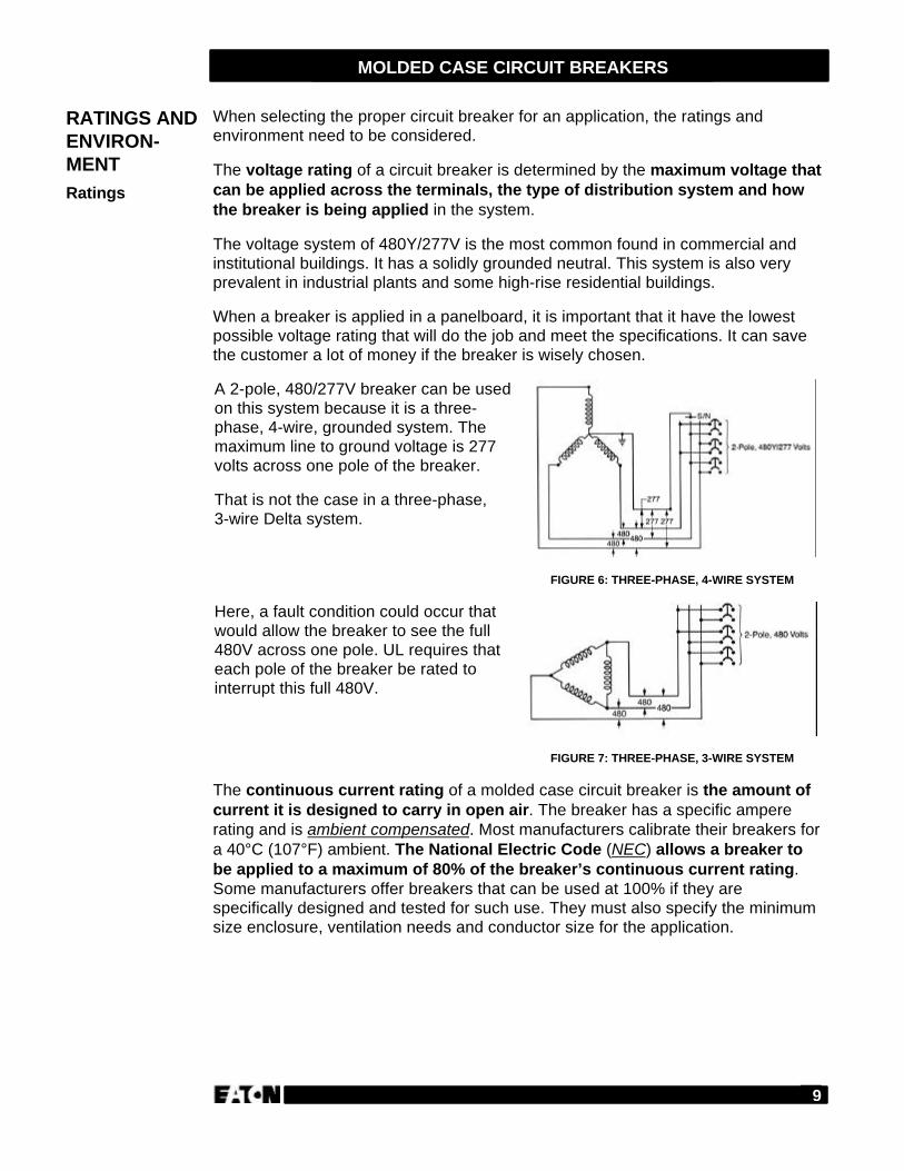
A 2-pole, 480/277V breaker can be usedon this system because it is a three-phase, 4-wire, grounded system. Themaximum line to ground voltage is 277volts across one pole of the breaker.
That is not the case in a three-phase,3-wire Delta system.
FIGURE 6: THREE-PHASE, 4-WIRE SYSTEM
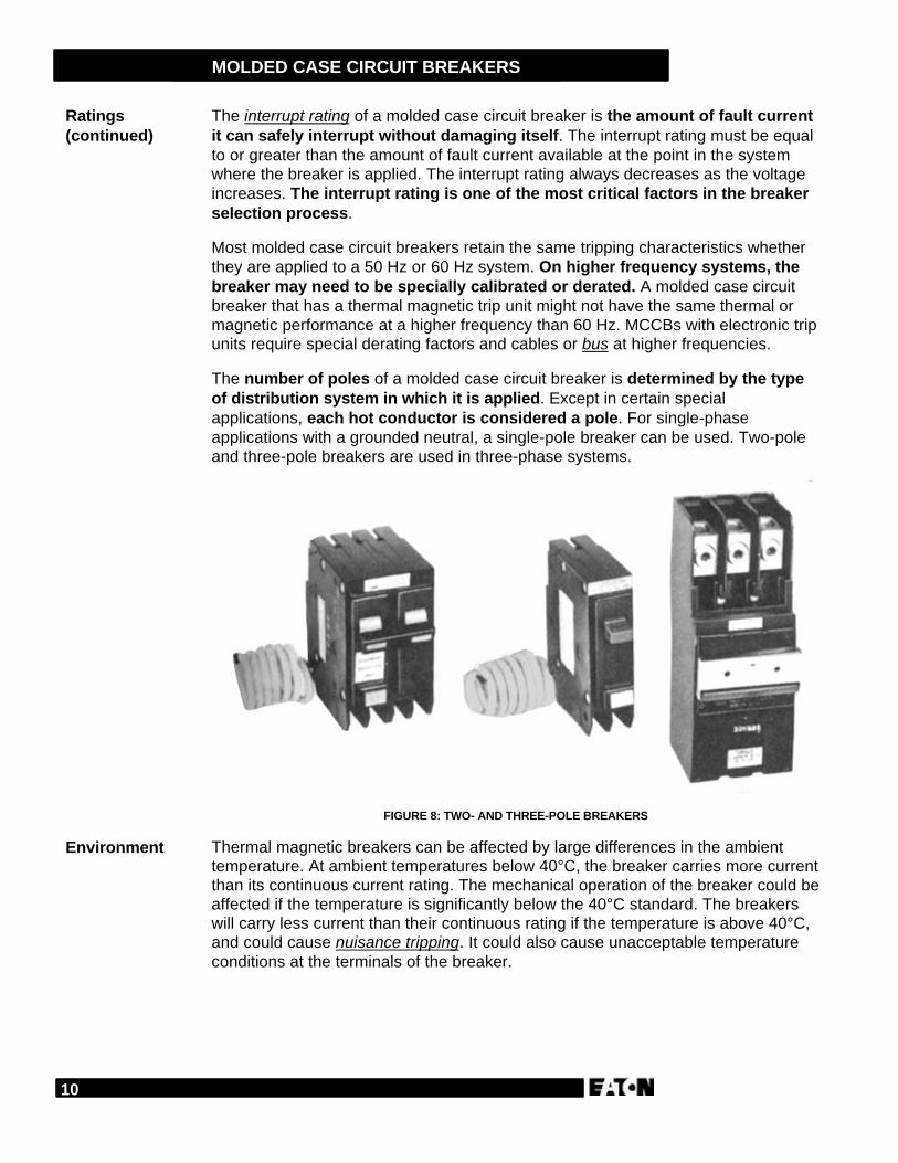
Here, a fault condition could occur thatwould allow the breaker to see the full480V across one pole. UL requires thateach pole of the breaker be rated tointerrupt this full 480V.
FIGURE 7: THREE-PHASE, 3-WIRE SYSTEM
The continuous current rating of a molded case circuit breaker is the amount ofcurrent it is designed to carry in open air. The breaker has a specific ampererating and is ambient compensated. Most manufacturers calibrate their breakers fora 40°C (107°F) ambient. The National Electric Code (NEC) allows a breaker tobe applied to a maximum of 80% of the breaker’s continuous current rating.Some manufacturers offer breakers that can be used at 100% if they arespecifically designed and tested for such use. They must also specify the minimumsize enclosure, ventilation needs and conductor size for the application.
RATINGS ANDENVIRON-MENTRatings
10
MOLDED CASE CIRCUIT BREAKERS
The interrupt rating of a molded case circuit breaker is the amount of fault currentit can safely interrupt without damaging itself. The interrupt rating must be equalto or greater than the amount of fault current available at the point in the systemwhere the breaker is applied. The interrupt rating always decreases as the voltageincreases. The interrupt rating is one of the most critical factors in the breakerselection process.
Most molded case circuit breakers retain the same tripping characteristics whetherthey are applied to a 50 Hz or 60 Hz system. On higher frequency systems, thebreaker may need to be specially calibrated or derated. A molded case circuitbreaker that has a thermal magnetic trip unit might not have the same thermal ormagnetic performance at a higher frequency than 60 Hz. MCCBs with electronic tripunits require special derating factors and cables or bus at higher frequencies.
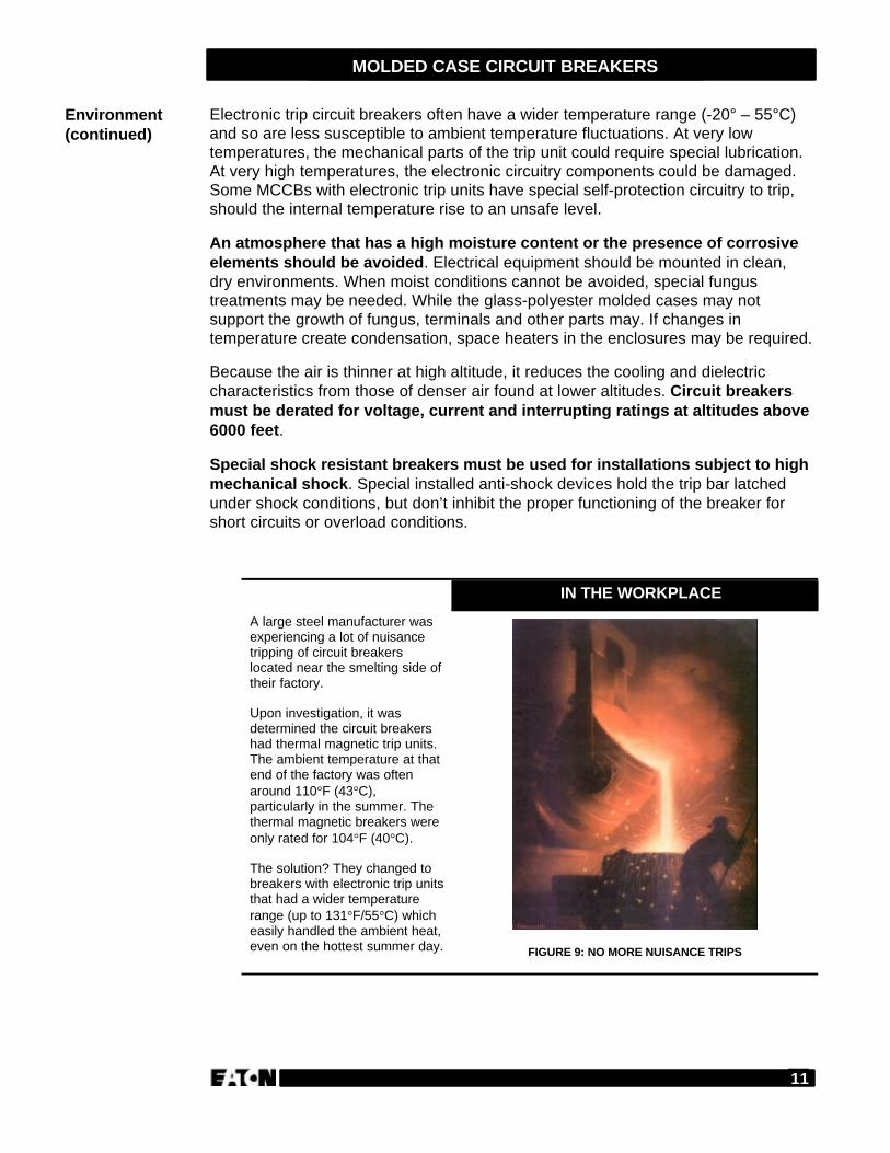
The number of poles of a molded case circuit breaker is determined by the typeof distribution system in which it is applied. Except in certain specialapplications, each hot conductor is considered a pole. For single-phaseapplications with a grounded neutral, a single-pole breaker can be used. Two-poleand three-pole breakers are used in three-phase systems.
FIGURE 8: TWO- AND THREE-POLE BREAKERS
Thermal magnetic breakers can be affected by large differences in the ambienttemperature. At ambient temperatures below 40°C, the breaker carries more currentthan its continuous current rating. The mechanical operation of the breaker could beaffected if the temperature is significantly below the 40°C standard. The breakerswill carry less current than their continuous rating if the temperature is above 40°C,and could cause nuisance tripping. It could also cause unacceptable temperatureconditions at the terminals of the breaker.
Ratings(continued)
Environment
11
MOLDED CASE CIRCUIT BREAKERS
Electronic trip circuit breakers often have a wider temperature range (-20° – 55°C)and so are less susceptible to ambient temperature fluctuations. At very lowtemperatures, the mechanical parts of the trip unit could require special lubrication.At very high temperatures, the electronic circuitry components could be damaged.Some MCCBs with electronic trip units have special self-protection circuitry to trip,should the internal temperature rise to an unsafe level.
An atmosphere that has a high moisture content or the presence of corrosiveelements should be avoided. Electrical equipment should be mounted in clean,dry environments. When moist conditions cannot be avoided, special fungustreatments may be needed. While the glass-polyester molded cases may notsupport the growth of fungus, terminals and other parts may. If changes intemperature create condensation, space heaters in the enclosures may be required.
Because the air is thinner at high altitude, it reduces the cooling and dielectriccharacteristics from those of denser air found at lower altitudes. Circuit breakersmust be derated for voltage, current and interrupting ratings at altitudes above6000 feet.
Special shock resistant breakers must be used for installations subject to highmechanical shock. Special installed anti-shock devices hold the trip bar latchedunder shock conditions, but don’t inhibit the proper functioning of the breaker forshort circuits or overload conditions.
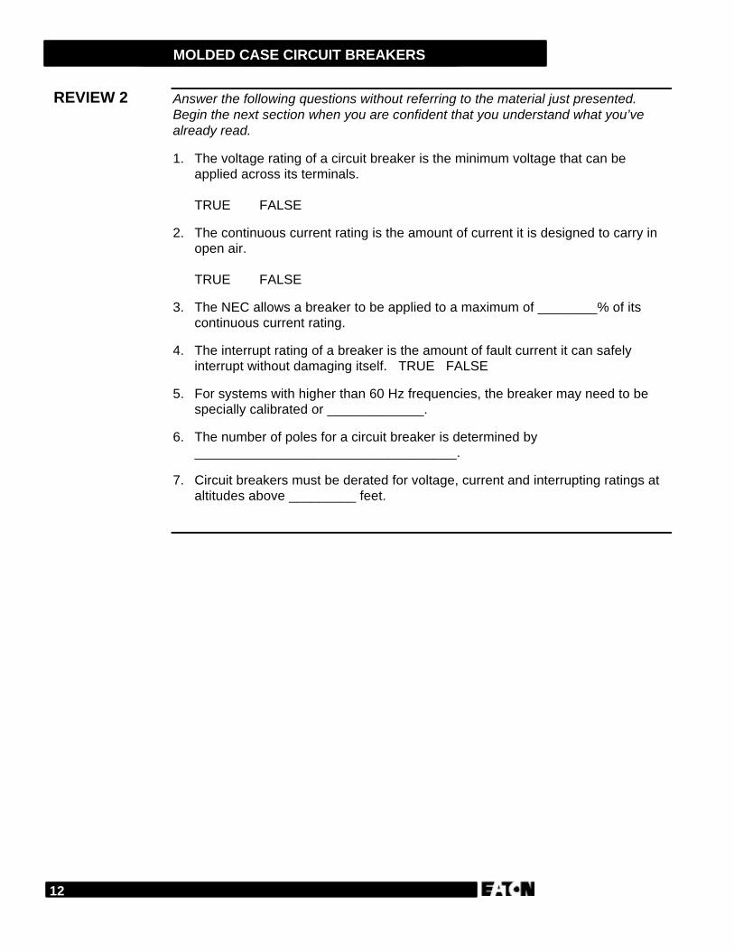
A large steel manufacturer wasexperiencing a lot of nuisancetripping of circuit breakerslocated near the smelting side oftheir factory.
Upon investigation, it wasdetermined the circuit breakershad thermal magnetic trip units.The ambient temperature at thatend of the factory was oftenaround 110°F (43°C),particularly in the summer. Thethermal magnetic breakers wereonly rated for 104°F (40°C).
The solution? They changed tobreakers with electronic trip unitsthat had a wider temperaturerange (up to 131°F/55°C) whicheasily handled the ambient heat,even on the hottest summer day. FIGURE 9: NO MORE NUISANCE TRIPS
Environment(continued)
IN THE WORKPLACE
12
MOLDED CASE CIRCUIT BREAKERS
Answer the following questions without referring to the material just presented.Begin the next section when you are confident that you understand what you’vealready read.
1. The voltage rating of a circuit breaker is the minimum voltage that can beapplied across its terminals.
TRUE FALSE
2. The continuous current rating is the amount of current it is designed to carry inopen air.
TRUE FALSE
3. The NEC allows a breaker to be applied to a maximum of ________% of itscontinuous current rating.
4. The interrupt rating of a breaker is the amount of fault current it can safelyinterrupt without damaging itself. TRUE FALSE
5. For systems with higher than 60 Hz frequencies, the breaker may need to bespecially calibrated or _____________.
6. The number of poles for a circuit breaker is determined by___________________________________.
7. Circuit breakers must be derated for voltage, current and interrupting ratings ataltitudes above _________ feet.
REVIEW 2
13
MOLDED CASE CIRCUIT BREAKERS
Since special considerations need to be taken when using circuit breakers withmotors, we will dedicate this section on their particular characteristics andapplications.
Most faults on a motor circuit are caused by a breakdown of the insulationwithin the motor windings. The initial fault current is usually low when comparedto the overall system capacity. However, because it causes an arcing condition, itcould cascade and short out more and more of the motor windings. If the fault isallowed to continue, serious motor and starter damages occur, increasing repaircosts. While fusible switches and thermal magnetic breakers can provide motorbranch circuit protection, the level of protection is not as effective against this typeof fault.
For this reason, the motor circuit protector was developed. A motor circuitprotector (MCP) operates on a magnetic only principle. It has a speciallydesigned current sensing coil in each of its three poles to provide sensitive low levelprotection. It can clear a fault faster than a fusible device. It does not, however,provide overload protection for the motor. As a result, a contactor with anoverload relay or motor starter must be used in conjunction with the motor circuitprotector. (See Module 19 for information on contactors, overload protection andstarters.)
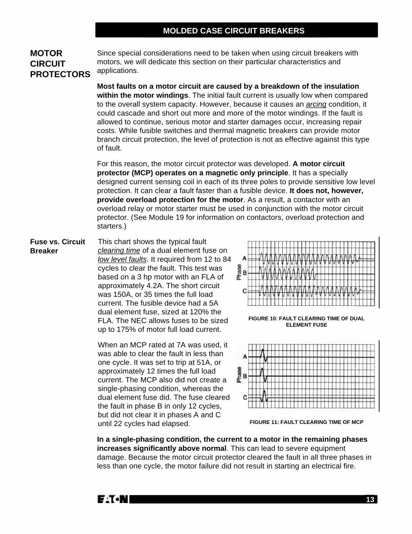
This chart shows the typical faultclearing time of a dual element fuse onlow level faults. It required from 12 to 84cycles to clear the fault. This test wasbased on a 3 hp motor with an FLA ofapproximately 4.2A. The short circuitwas 150A, or 35 times the full loadcurrent. The fusible device had a 5Adual element fuse, sized at 120% theFLA. The NEC allows fuses to be sizedup to 175% of motor full load current.
FIGURE 10: FAULT CLEARING TIME OF DUALELEMENT FUSE
When an MCP rated at 7A was used, itwas able to clear the fault in less thanone cycle. It was set to trip at 51A, orapproximately 12 times the full loadcurrent. The MCP also did not create asingle-phasing condition, whereas thedual element fuse did. The fuse clearedthe fault in phase B in only 12 cycles,but did not clear it in phases A and Cuntil 22 cycles had elapsed. FIGURE 11: FAULT CLEARING TIME OF MCP
In a single-phasing condition, the current to a motor in the remaining phasesincreases significantly above normal. This can lead to severe equipmentdamage. Because the motor circuit protector cleared the fault in all three phases inless than one cycle, the motor failure did not result in starting an electrical fire.
MOTORCIRCUITPROTECTORS
Fuse vs. CircuitBreaker
14
MOLDED CASE CIRCUIT BREAKERS
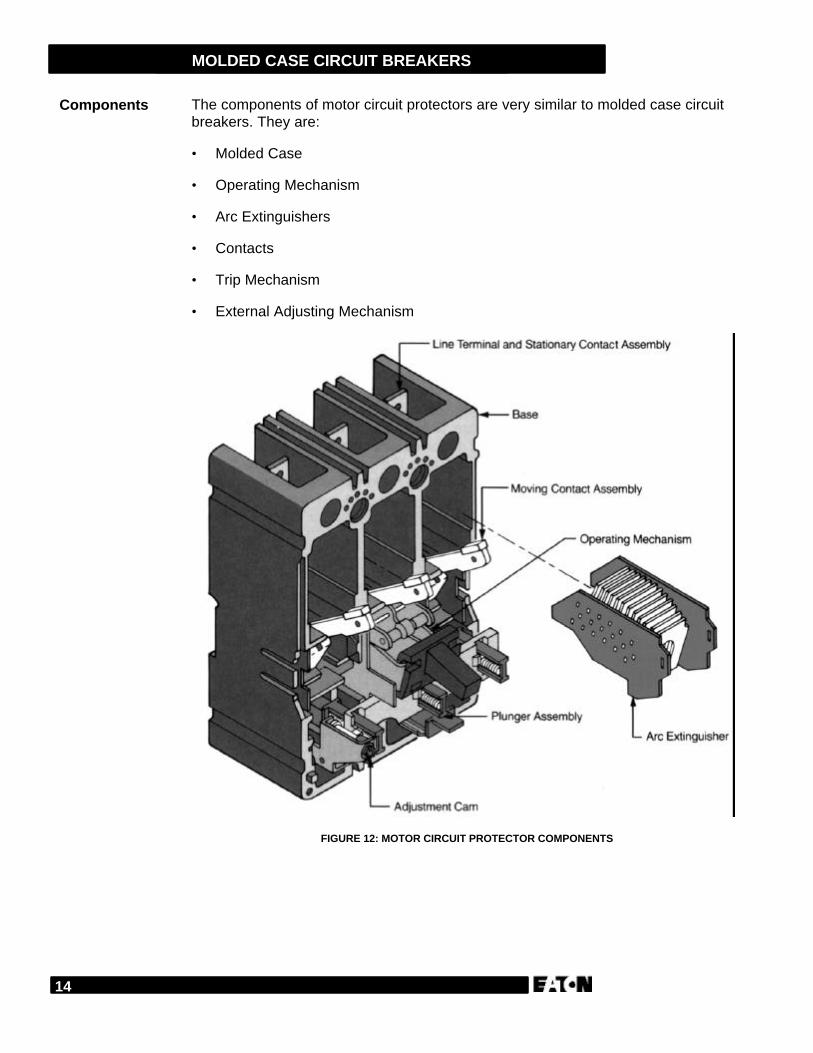
The components of motor circuit protectors are very similar to molded case circuitbreakers. They are:
• Molded Case
• Operating Mechanism
• Arc Extinguishers
• Contacts
• Trip Mechanism
• External Adjusting Mechanism
FIGURE 12: MOTOR CIRCUIT PROTECTOR COMPONENTS
Components
15
MOLDED CASE CIRCUIT BREAKERS
Motor circuit protectors disconnect the motor load from an electrical supply underthree conditions. They are:
• When the handle is switched to OFF.
• When an automatic trip operation occurs.
• When a manual trip is initiated with a push-to-trip button.
As with the molded case circuit breakers, the operating mechanism is a spring-loaded toggle that provides quick-make, quick-break and trip-free operation.
Its design provides an increased air gap between the stationary and moveablecontacts when in the tripped position. This air gap results in greater arcextinguishing during contact opening and provides higher interrupt ratings.
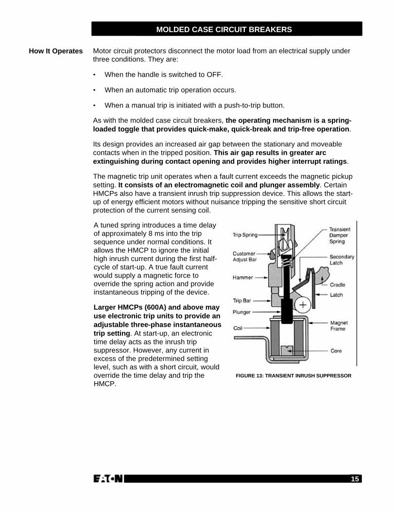
The magnetic trip unit operates when a fault current exceeds the magnetic pickupsetting. It consists of an electromagnetic coil and plunger assembly. CertainHMCPs also have a transient inrush trip suppression device. This allows the start-up of energy efficient motors without nuisance tripping the sensitive short circuitprotection of the current sensing coil.
A tuned spring introduces a time delayof approximately 8 ms into the tripsequence under normal conditions. Itallows the HMCP to ignore the initialhigh inrush current during the first half-cycle of start-up. A true fault currentwould supply a magnetic force tooverride the spring action and provideinstantaneous tripping of the device.
Larger HMCPs (600A) and above mayuse electronic trip units to provide anadjustable three-phase instantaneoustrip setting. At start-up, an electronictime delay acts as the inrush tripsuppressor. However, any current inexcess of the predetermined settinglevel, such as with a short circuit, wouldoverride the time delay and trip theHMCP.
FIGURE 13: TRANSIENT INRUSH SUPPRESSOR
How It Operates
16
MOLDED CASE CIRCUIT BREAKERS
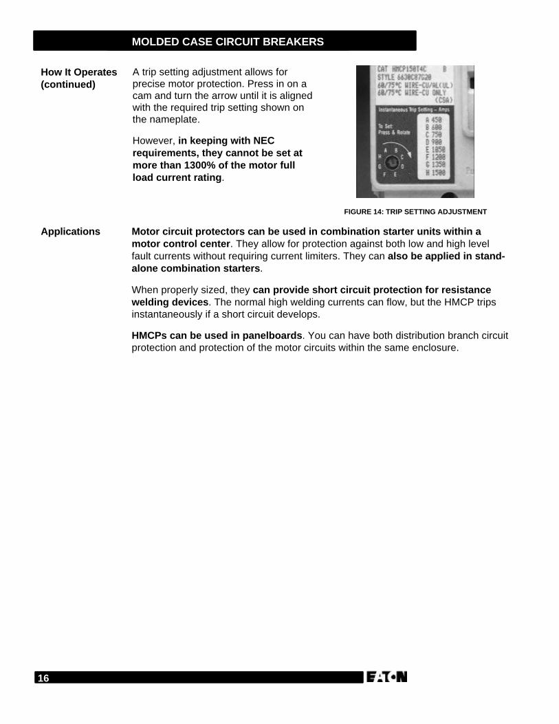
A trip setting adjustment allows forprecise motor protection. Press in on acam and turn the arrow until it is alignedwith the required trip setting shown onthe nameplate.
However, in keeping with NECrequirements, they cannot be set atmore than 1300% of the motor fullload current rating.
FIGURE 14: TRIP SETTING ADJUSTMENT
Motor circuit protectors can be used in combination starter units within amotor control center. They allow for protection against both low and high levelfault currents without requiring current limiters. They can also be applied in stand-alone combination starters.
When properly sized, they can provide short circuit protection for resistancewelding devices. The normal high welding currents can flow, but the HMCP tripsinstantaneously if a short circuit develops.
HMCPs can be used in panelboards. You can have both distribution branch circuitprotection and protection of the motor circuits within the same enclosure.
How It Operates(continued)
Applications
17
MOLDED CASE CIRCUIT BREAKERS
Answer the following questions without referring to the material just presented.Begin the next section when you are confident that you understand what you’vealready read.
1. Most faults on a motor circuit are caused by a breakdown of the insulation withinthe motor windings.
TRUE FALSE
2. A motor circuit protector operates on a ___________ _____ principle.
3. An MCP provides overload protection for the motor.
TRUE FALSE
4. In a single-phasing condition, current to the motor in the remaining phasesincreases significantly.
TRUE FALSE
5. The operating mechanism provides quick-make, quick break and trip-freeoperation.
TRUE FALSE
6. The NEC allows an HMCP to be adjusted to a maximum of ________% of themotor FLA rating.
7. HMCPs cannot be used in panelboards.
TRUE FALSE
REVIEW 3
18
MOLDED CASE CIRCUIT BREAKERS
When a comparison is made between a fusible switch and a molded case circuitbreaker, it is easy to see the application flexibility MCCBs provide. This is evenmore apparent when you look at the array of accessories and modificationsavailable. We are going to review in general what is available with a briefexplanation of their purpose and applications. We will not cover specificaccessories for specific lines of breakers in this module.
We are going to divide our review into the following categories:
• Operational Devices
• Termination Devices
• Handle Operating Devices
• Lock and Interlock Devices
• Miscellaneous Devices
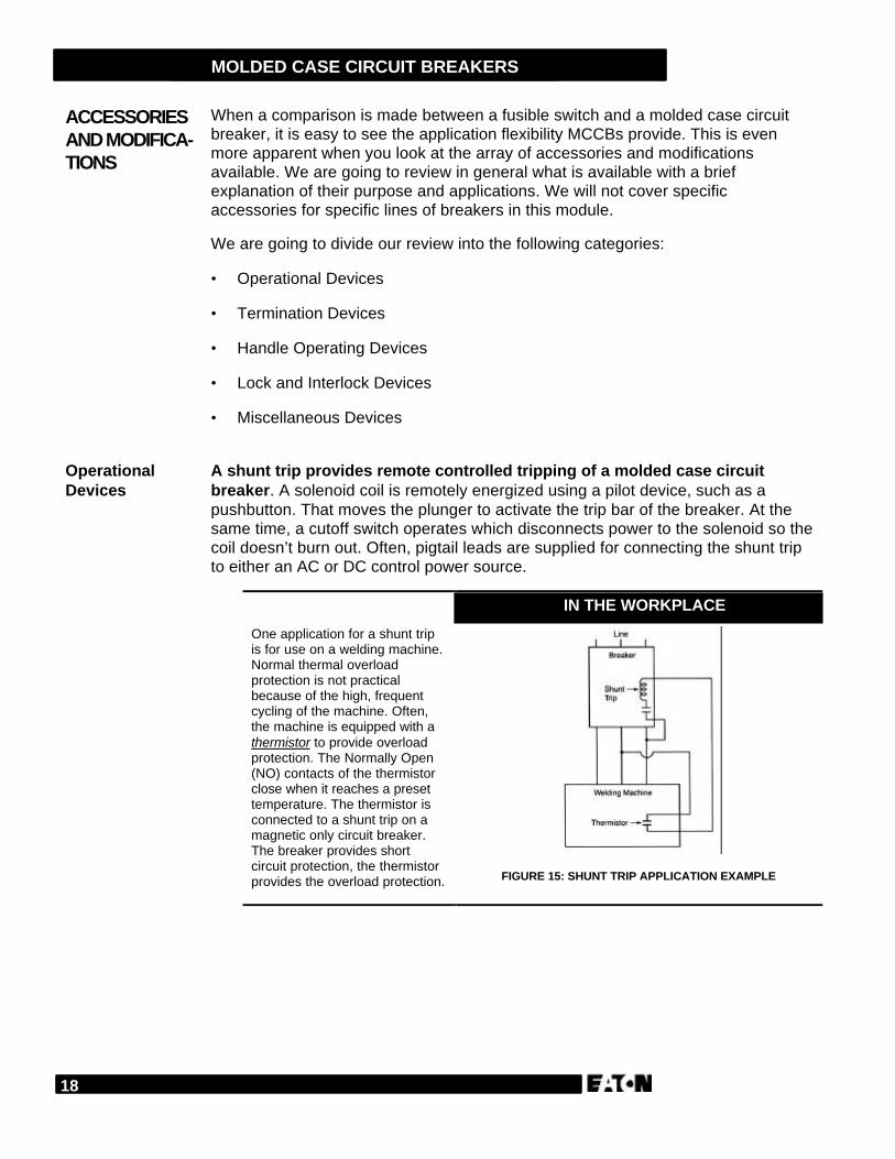
A shunt trip provides remote controlled tripping of a molded case circuitbreaker. A solenoid coil is remotely energized using a pilot device, such as apushbutton. That moves the plunger to activate the trip bar of the breaker. At thesame time, a cutoff switch operates which disconnects power to the solenoid so thecoil doesn’t burn out. Often, pigtail leads are supplied for connecting the shunt tripto either an AC or DC control power source.
One application for a shunt tripis for use on a welding machine.Normal thermal overloadprotection is not practicalbecause of the high, frequentcycling of the machine. Often,the machine is equipped with athermistor to provide overloadprotection. The Normally Open(NO) contacts of the thermistorclose when it reaches a presettemperature. The thermistor isconnected to a shunt trip on amagnetic only circuit breaker.The breaker provides shortcircuit protection, the thermistorprovides the overload protection. FIGURE 15: SHUNT TRIP APPLICATION EXAMPLE
ACCESSORIESAND MODIFICA-TIONS
OperationalDevices
IN THE WORKPLACE
19
MOLDED CASE CIRCUIT BREAKERS
An undervoltage release mechanism trips the breaker whenever the voltagefalls below a predetermined level. These undervoltage release mechanisms(UVRs) come in two different styles:
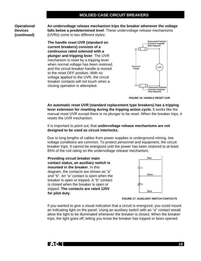
The handle reset UVR (standard oncurrent breakers) consists of acontinuous rated solenoid with aplunger and tripping lever. The UVRmechanism is reset by a tripping leverwhen normal voltage has been restored,and the circuit breaker handle is movedto the reset OFF position. With novoltage applied to the UVR, the circuitbreaker contacts will not touch when aclosing operation is attempted.
FIGURE 16: HANDLE RESET UVR
An automatic reset UVR (standard replacement type breakers) has a trippinglever extension for resetting during the tripping action cycle. It works like themanual reset UVR except there is no plunger to be reset. When the breaker trips, itresets the UVR mechanism.
It is important to point out, that undervoltage release mechanisms are notdesigned to be used as circuit interlocks.
Due to long lengths of cables from power supplies in underground mining, lowvoltage conditions are common. To protect personnel and equipment, the circuitbreaker trips. It cannot be energized until the power has been restored to at least85% of the coil rating on the undervoltage release mechanism.
Providing circuit breaker maincontact status, an auxiliary switch ismounted in the breaker. In thisdiagram, the contacts are shown as “a”and “b”. An “a” contact is open when thebreaker is open or tripped. A “b” contactis closed when the breaker is open ortripped. The contacts are rated 120Vfor pilot duty.
FIGURE 17: AUXILIARY SWITCH CONTACTS
If you wanted to give a visual indication that a circuit is energized, you could mountan indicating light on the panel. Using an auxiliary switch with an “a” contact wouldallow the light to be illuminated whenever the breaker is closed. When the breakertrips, the light goes off, letting you know the breaker has tripped or been opened.
OperationalDevices(continued)
20
MOLDED CASE CIRCUIT BREAKERS
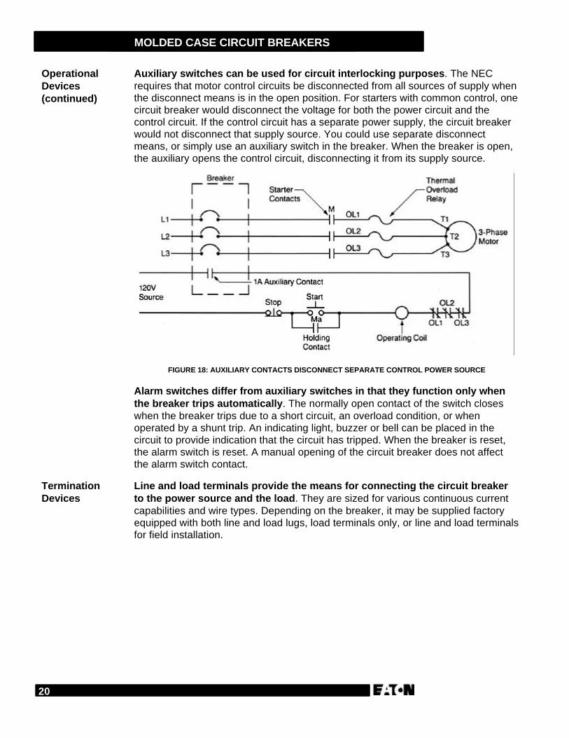
Auxiliary switches can be used for circuit interlocking purposes. The NECrequires that motor control circuits be disconnected from all sources of supply whenthe disconnect means is in the open position. For starters with common control, onecircuit breaker would disconnect the voltage for both the power circuit and thecontrol circuit. If the control circuit has a separate power supply, the circuit breakerwould not disconnect that supply source. You could use separate disconnectmeans, or simply use an auxiliary switch in the breaker. When the breaker is open,the auxiliary opens the control circuit, disconnecting it from its supply source.
FIGURE 18: AUXILIARY CONTACTS DISCONNECT SEPARATE CONTROL POWER SOURCE
Alarm switches differ from auxiliary switches in that they function only whenthe breaker trips automatically. The normally open contact of the switch closeswhen the breaker trips due to a short circuit, an overload condition, or whenoperated by a shunt trip. An indicating light, buzzer or bell can be placed in thecircuit to provide indication that the circuit has tripped. When the breaker is reset,the alarm switch is reset. A manual opening of the circuit breaker does not affectthe alarm switch contact.
Line and load terminals provide the means for connecting the circuit breakerto the power source and the load. They are sized for various continuous currentcapabilities and wire types. Depending on the breaker, it may be supplied factoryequipped with both line and load lugs, load terminals only, or line and load terminalsfor field installation.
OperationalDevices(continued)
TerminationDevices
21
MOLDED CASE CIRCUIT BREAKERS
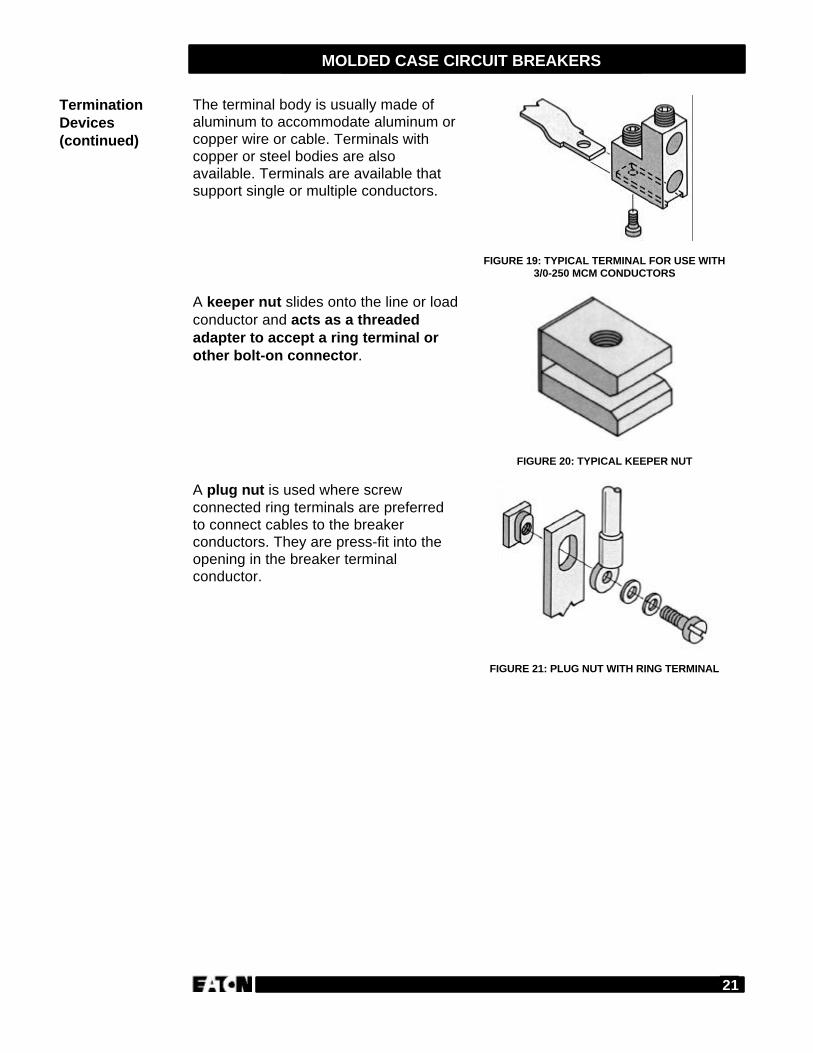
The terminal body is usually made ofaluminum to accommodate aluminum orcopper wire or cable. Terminals withcopper or steel bodies are alsoavailable. Terminals are available thatsupport single or multiple conductors.
FIGURE 19: TYPICAL TERMINAL FOR USE WITH3/0-250 MCM CONDUCTORS
A keeper nut slides onto the line or loadconductor and acts as a threadedadapter to accept a ring terminal orother bolt-on connector.
FIGURE 20: TYPICAL KEEPER NUT
A plug nut is used where screwconnected ring terminals are preferredto connect cables to the breakerconductors. They are press-fit into theopening in the breaker terminalconductor.
FIGURE 21: PLUG NUT WITH RING TERMINAL
TerminationDevices(continued)
22
MOLDED CASE CIRCUIT BREAKERS
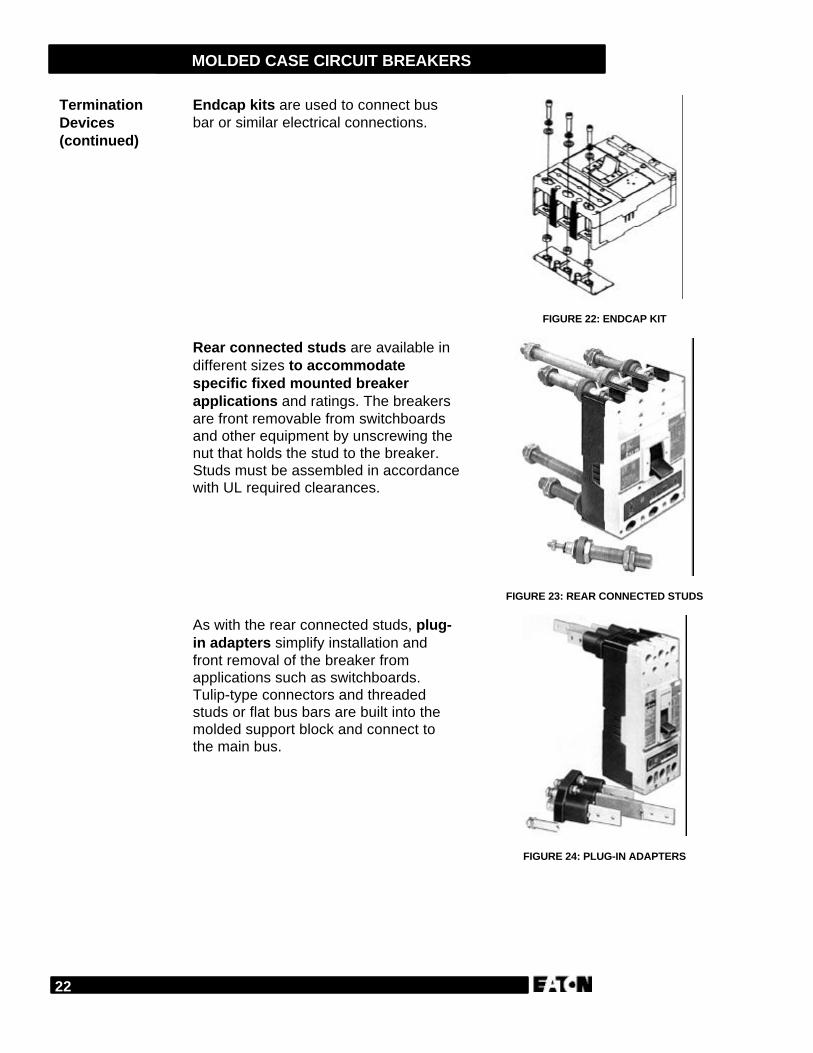
Endcap kits are used to connect busbar or similar electrical connections.
FIGURE 22: ENDCAP KIT
Rear connected studs are available indifferent sizes to accommodatespecific fixed mounted breakerapplications and ratings. The breakersare front removable from switchboardsand other equipment by unscrewing thenut that holds the stud to the breaker.Studs must be assembled in accordancewith UL required clearances.
FIGURE 23: REAR CONNECTED STUDS
As with the rear connected studs, plug-in adapters simplify installation andfront removal of the breaker fromapplications such as switchboards.Tulip-type connectors and threadedstuds or flat bus bars are built into themolded support block and connect tothe main bus.
FIGURE 24: PLUG-IN ADAPTERS
TerminationDevices(continued)
23
MOLDED CASE CIRCUIT BREAKERS
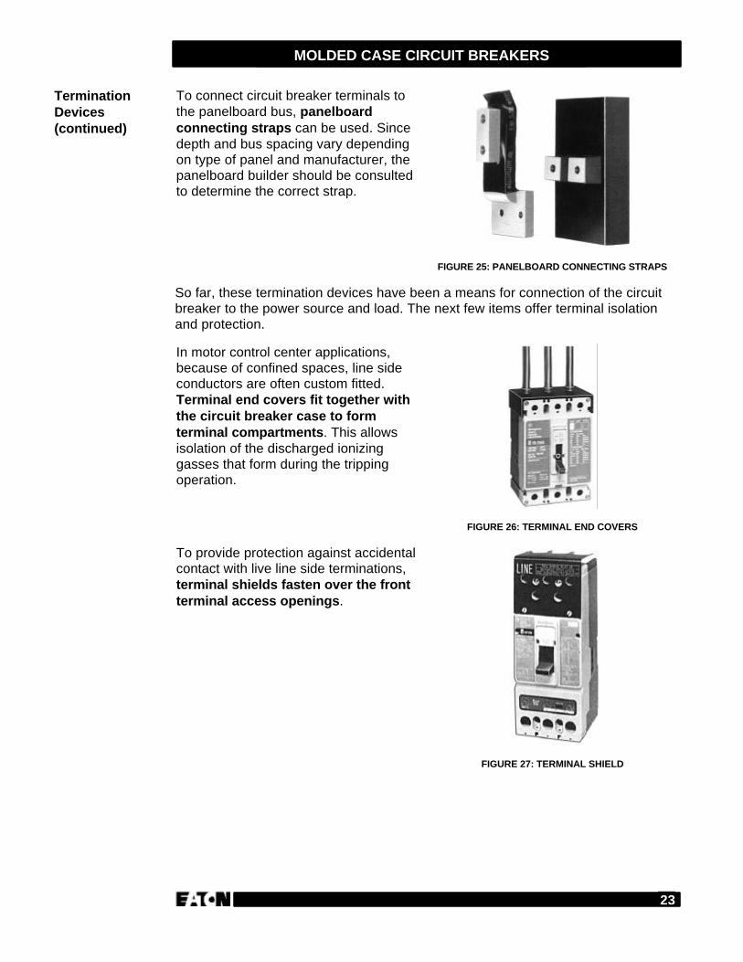
To connect circuit breaker terminals tothe panelboard bus, panelboardconnecting straps can be used. Sincedepth and bus spacing vary dependingon type of panel and manufacturer, thepanelboard builder should be consultedto determine the correct strap.
FIGURE 25: PANELBOARD CONNECTING STRAPS
So far, these termination devices have been a means for connection of the circuitbreaker to the power source and load. The next few items offer terminal isolationand protection.
In motor control center applications,because of confined spaces, line sideconductors are often custom fitted.Terminal end covers fit together withthe circuit breaker case to formterminal compartments. This allowsisolation of the discharged ionizinggasses that form during the trippingoperation.
FIGURE 26: TERMINAL END COVERS
To provide protection against accidentalcontact with live line side terminations,terminal shields fasten over the frontterminal access openings.
FIGURE 27: TERMINAL SHIELD
TerminationDevices(continued)
24
MOLDED CASE CIRCUIT BREAKERS
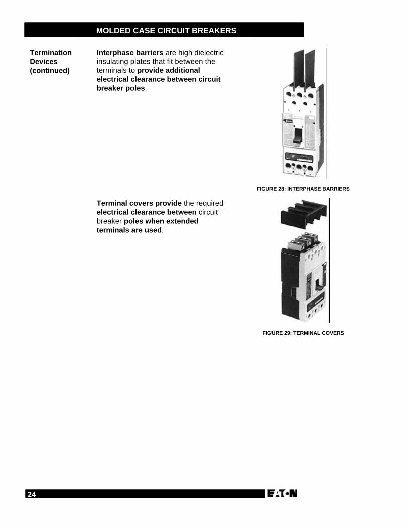
Interphase barriers are high dielectricinsulating plates that fit between theterminals to provide additionalelectrical clearance between circuitbreaker poles.
FIGURE 28: INTERPHASE BARRIERS
Terminal covers provide the requiredelectrical clearance between circuitbreaker poles when extendedterminals are used.
FIGURE 29: TERMINAL COVERS
TerminationDevices(continued)
25
MOLDED CASE CIRCUIT BREAKERS
Answer the following questions without referring to the material just presented.Begin the next section when you are confident that you understand what you’vealready read.
1. A shunt trip provides remote controlled tripping of a circuit breaker.
TRUE FALSE
2. An undervoltage release mechanism trips the breaker whenever the voltage___________________ a predetermined level.
3. Auxiliary switches can be used for circuit interlocking.
TRUE FALSE
4. _________ and ________ terminals provide the means for connecting thecircuit breaker to the power source and the load.
5. Interphase barriers provide additional electrical clearance between the circuitbreaker poles.
TRUE FALSE
REVIEW 4
26
MOLDED CASE CIRCUIT BREAKERS
Handle operating devices provide indirect electrical or manual operation of thecircuit breaker handle.
Electrical operators provide complete remote control of a molded case circuitbreaker by means of a pushbutton or similar pilot device. When energized froma remote location, the operator mechanism moves the circuit breaker handle toeither the ON or OFF position. Shunt trips and undervoltage release mechanismscan only be used to trip the breaker. Electrical operators deliver a positive switchingaction. In case of a power failure, means are provided for manual operation. Theycome in a variety of designs and, depending on the circuit breaker type, aremounted in different ways.
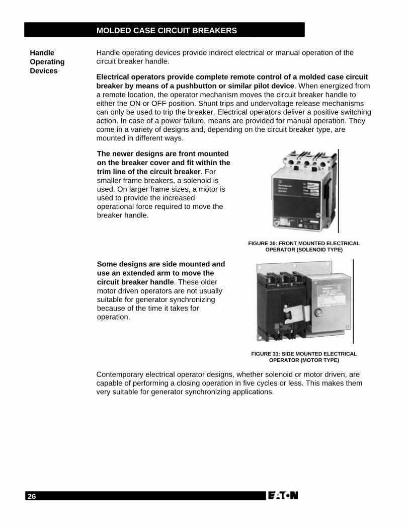
The newer designs are front mountedon the breaker cover and fit within thetrim line of the circuit breaker. Forsmaller frame breakers, a solenoid isused. On larger frame sizes, a motor isused to provide the increasedoperational force required to move thebreaker handle.
FIGURE 30: FRONT MOUNTED ELECTRICALOPERATOR (SOLENOID TYPE)
Some designs are side mounted anduse an extended arm to move thecircuit breaker handle. These oldermotor driven operators are not usuallysuitable for generator synchronizingbecause of the time it takes foroperation.
FIGURE 31: SIDE MOUNTED ELECTRICALOPERATOR (MOTOR TYPE)
Contemporary electrical operator designs, whether solenoid or motor driven, arecapable of performing a closing operation in five cycles or less. This makes themvery suitable for generator synchronizing applications.
HandleOperatingDevices
27
MOLDED CASE CIRCUIT BREAKERS
Handle mechanisms allow for the manual operation of the circuit breakertoggle handle. These mechanical devices allow personnel to open and close thebreaker without opening the enclosure in which the breaker is mounted. They comein a variety of designs for different applications and enclosure types.
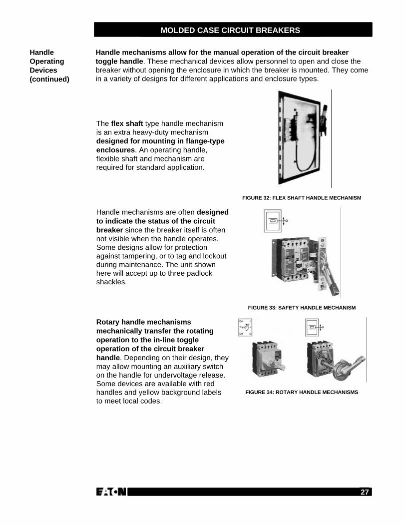
The flex shaft type handle mechanismis an extra heavy-duty mechanismdesigned for mounting in flange-typeenclosures. An operating handle,flexible shaft and mechanism arerequired for standard application.
FIGURE 32: FLEX SHAFT HANDLE MECHANISM
Handle mechanisms are often designedto indicate the status of the circuitbreaker since the breaker itself is oftennot visible when the handle operates.Some designs allow for protectionagainst tampering, or to tag and lockoutduring maintenance. The unit shownhere will accept up to three padlockshackles.
FIGURE 33: SAFETY HANDLE MECHANISM
Rotary handle mechanismsmechanically transfer the rotatingoperation to the in-line toggleoperation of the circuit breakerhandle. Depending on their design, theymay allow mounting an auxiliary switchon the handle for undervoltage release.Some devices are available with redhandles and yellow background labelsto meet local codes.
FIGURE 34: ROTARY HANDLE MECHANISMS
HandleOperatingDevices(continued)
28
MOLDED CASE CIRCUIT BREAKERS
Lock and interlock devices are used to deter undesired circuit breaker operationand establish interlocked control systems. They do not interfere with the trip-freeoperation of the molded case circuit breaker.
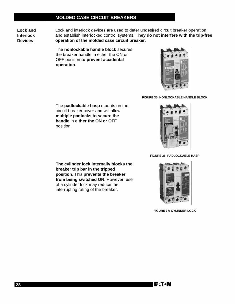
The nonlockable handle block securesthe breaker handle in either the ON orOFF position to prevent accidentaloperation.
FIGURE 35: NONLOCKABLE HANDLE BLOCK
The padlockable hasp mounts on thecircuit breaker cover and will allowmultiple padlocks to secure thehandle in either the ON or OFFposition.
FIGURE 36: PADLOCKABLE HASP
The cylinder lock internally blocks thebreaker trip bar in the trippedposition. This prevents the breakerfrom being switched ON. However, useof a cylinder lock may reduce theinterrupting rating of the breaker.
FIGURE 37: CYLINDER LOCK
Lock andInterlockDevices
29
MOLDED CASE CIRCUIT BREAKERS
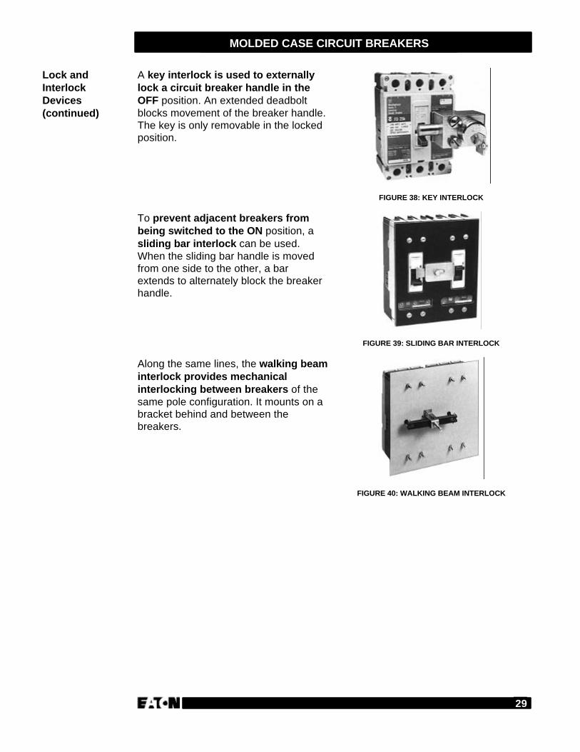
A key interlock is used to externallylock a circuit breaker handle in theOFF position. An extended deadboltblocks movement of the breaker handle.The key is only removable in the lockedposition.
FIGURE 38: KEY INTERLOCK
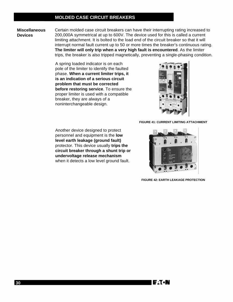
To prevent adjacent breakers frombeing switched to the ON position, asliding bar interlock can be used.When the sliding bar handle is movedfrom one side to the other, a barextends to alternately block the breakerhandle.
FIGURE 39: SLIDING BAR INTERLOCK
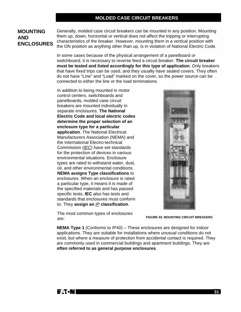
Along the same lines, the walking beaminterlock provides mechanicalinterlocking between breakers of thesame pole configuration. It mounts on abracket behind and between thebreakers.
FIGURE 40: WALKING BEAM INTERLOCK
Lock andInterlockDevices(continued)
30
MOLDED CASE CIRCUIT BREAKERS
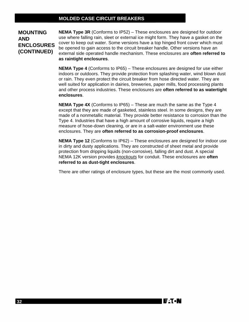
Certain molded case circuit breakers can have their interrupting rating increased to200,000A symmetrical at up to 600V. The device used for this is called a currentlimiting attachment. It is bolted to the load end of the circuit breaker so that it willinterrupt normal fault current up to 50 or more times the breaker’s continuous rating.The limiter will only trip when a very high fault is encountered. As the limitertrips, the breaker is also tripped magnetically, preventing a single-phasing condition.
A spring loaded indicator is on eachpole of the limiter to identify the faultedphase. When a current limiter trips, itis an indication of a serious circuitproblem that must be correctedbefore restoring service. To ensure theproper limiter is used with a compatiblebreaker, they are always of anoninterchangeable design.
FIGURE 41: CURRENT LIMITING ATTACHMENT
Another device designed to protectpersonnel and equipment is the lowlevel earth leakage (ground fault)protector. This device usually trips thecircuit breaker through a shunt trip orundervoltage release mechanismwhen it detects a low level ground fault.
FIGURE 42: EARTH LEAKAGE PROTECTION
MiscellaneousDevices
31
MOLDED CASE CIRCUIT BREAKERS
Generally, molded case circuit breakers can be mounted in any position. Mountingthem up, down, horizontal or vertical does not affect the tripping or interruptingcharacteristics of the breaker. However, mounting them in a vertical position withthe ON position as anything other than up, is in violation of National Electric Code.
In some cases because of the physical arrangement of a panelboard orswitchboard, it is necessary to reverse feed a circuit breaker. The circuit breakermust be tested and listed accordingly for this type of application. Only breakersthat have fixed trips can be used, and they usually have sealed covers. They oftendo not have “Line” and “Load” marked on the cover, so the power source can beconnected to either the line or the load terminations.
In addition to being mounted in motorcontrol centers, switchboards andpanelboards, molded case circuitbreakers are mounted individually inseparate enclosures. The NationalElectric Code and local electric codesdetermine the proper selection of anenclosure type for a particularapplication. The National ElectricalManufacturers Association (NEMA) andthe International Electro-technicalCommission (IEC) have set standardsfor the protection of devices in variousenvironmental situations. Enclosuretypes are rated to withstand water, dust,oil, and other environmental conditions.NEMA assigns Type classifications toenclosures. When an enclosure is rateda particular type, it means it is made ofthe specified materials and has passedspecific tests. IEC also has tests andstandards that enclosures must conformto. They assign an IP classification.
The most common types of enclosuresare: FIGURE 43: MOUNTING CIRCUIT BREAKERS
NEMA Type 1 (Conforms to IP40) – These enclosures are designed for indoorapplications. They are suitable for installations where unusual conditions do notexist, but where a measure of protection from accidental contact is required. Theyare commonly used in commercial buildings and apartment buildings. They areoften referred to as general purpose enclosures.
MOUNTINGANDENCLOSURES
32
MOLDED CASE CIRCUIT BREAKERS
NEMA Type 3R (Conforms to IP52) – These enclosures are designed for outdooruse where falling rain, sleet or external ice might form. They have a gasket on thecover to keep out water. Some versions have a top hinged front cover which mustbe opened to gain access to the circuit breaker handle. Other versions have anexternal side operated handle mechanism. These enclosures are often referred toas raintight enclosures.
NEMA Type 4 (Conforms to IP65) – These enclosures are designed for use eitherindoors or outdoors. They provide protection from splashing water, wind blown dustor rain. They even protect the circuit breaker from hose directed water. They arewell suited for application in dairies, breweries, paper mills, food processing plantsand other process industries. These enclosures are often referred to as watertightenclosures.
NEMA Type 4X (Conforms to IP65) – These are much the same as the Type 4except that they are made of gasketed, stainless steel. In some designs, they aremade of a nonmetallic material. They provide better resistance to corrosion than theType 4. Industries that have a high amount of corrosive liquids, require a highmeasure of hose-down cleaning, or are in a salt-water environment use theseenclosures. They are often referred to as corrosion-proof enclosures.
NEMA Type 12 (Conforms to IP62) – These enclosures are designed for indoor usein dirty and dusty applications. They are constructed of sheet metal and provideprotection from dripping liquids (non-corrosive), falling dirt and dust. A specialNEMA 12K version provides knockouts for conduit. These enclosures are oftenreferred to as dust-tight enclosures.
There are other ratings of enclosure types, but these are the most commonly used.
MOUNTINGANDENCLOSURES(CONTINUED)
33
MOLDED CASE CIRCUIT BREAKERS
The selection of molded case circuit breakers is generally determined in two ways:
• For protection of non-motor circuits.
• For protection of motor circuits.
We will discuss protection of non-motor circuits first.
Non-motor circuit applications usually center around cable protection and requiremolded case circuit breakers with both overload and short circuit capabilities. Theyshould be able to distinguish between harmless and destructive conditions, andfunction appropriately for its application. It is very important that the MCCB selectedbe adequately rated and equipped for all the electrical and physical conditions thatare likely to exist when the system is energized.
The standard selection factors for molded case circuit breakers include:
• Voltage Rating
• Frequency
• Continuous Current Rating
• Interrupting Rating
• Number of Poles
• Fixed or Interchangeable Trip Unit
• Trip Unit Functions
• Accessories
The selection of an HMCP is based on the full load current of the motor it is toprotect. Data shown in the National Electric Code (tables 430-148 and 430-150) listthe full load currents of induction motors running at speeds normal for belted motorsand with normal torque characteristics. However, actual motor nameplate ratingsshould be used for selecting the motor running overload protection.
Other considerations in the selection of HMCPs include:
• The ambient temperature outside the enclosure should not exceed 40°C(104°F).
• Infrequent starting, stopping and reversing of the motor.
• Motor accelerating time of 10 seconds or less.
• Locked rotor rating is a maximum of six times the motor FLA rating.
HELPING THECUSTOMER
ProtectingNon-MotorCircuits
Protecting MotorCircuits
34
MOLDED CASE CIRCUIT BREAKERS
Answer the following questions without referring to the material just presented.
1. Electrical operating devices provide complete remote control of a molded casecircuit breaker.
TRUE FALSE
2. Handle mechanisms are often designed to ________ ________ of the circuitbreaker.
3. Rotary handle mechanisms mechanically transfer the rotating operation to thein-line toggle operation of the breaker handle.
TRUE FALSE
4. The padlockable hasp will allow securing the circuit breaker handle only in theOFF position.
TRUE FALSE
5. To prevent adjacent breakers from being switched to the ON position, you canuse a ___________________________________.
6. A current limiting attachment can increase a circuit breaker’s interrupting rating.
TRUE FALSE
7. __________ and ____________ determine which type of enclosure is used fora given application.
REVIEW 5
35
MOLDED CASE CIRCUIT BREAKERS
AmbientCompensated
An electromechanical circuit breaker whose trip element iscalibrated/adjusted to perform as required in a specificsurrounding temperature condition.
ANSI Abbreviation for American National Standards Institute. Itdoes not develop standards, but functions as a coordinatingbody for the purpose of encouraging development andadoption of worthwhile standards.
Arcing The discharge of electric current across a gap between twopoints. It occurs between breaker contacts each time abreaker interrupts a current.
Bus The conductor(s), usually made of copper or aluminum,which carries the current and serves as a commonconnection for two or more circuits.
Clearing Time(Circuit Breaker)
The total elapsed time between the time the specifiedovercurrent causes a release device to be actuated and theinstant of final arc extinction on all poles of the primaryarcing contacts.
Clearing Time(Fuse)
The total elapsed time between the beginning of thespecified overcurrent and the final interruption of the circuit.It is the sum of the melting time and the arcing time.
Deionization The process of removing conduction ions, thus permittingarc extinction.
Drawout Mount Breaker can be moved into or out of its structure withoutunbolting, often on a Racking mechanism.
Fault Current The surge of amperage created during an electrical failing.
Fixed Mounted The breaker is bolted into a fixed position with bus or cablemechanically bolted to breaker terminations.
Fixed Trip The trip unit of the circuit breaker is set for a specific triprating and cannot be adjusted if a new trip rating is needed.The circuit breaker must be replaced.
IEC International Electro-technical Commission.
InterchangeableTrip Unit
If a new trip rating is required for an application, only thetrip unit needs to be replaced, up to the maximum currentrating of the breaker frame.
Interrupt Rating The maximum short circuit current that an overcurrentprotective device can safely interrupt.
GLOSSARY
36
MOLDED CASE CIRCUIT BREAKERS
IP Ingress Protection: protection from the entry of dust, liquid,or other material into the enclosure and/or protection ofhuman contact with live electrical parts.
Knockouts Pre-stamped holes for the insertion of conduit orconductors into an enclosure.
Low Level Fault Can range in magnitude from just above full load current to10 or more times normal current. Does not usually causenoticeable damage immediately, but can lead to eventualproblems.
Molded CaseCircuit Breaker
A circuit breakers designed to provide circuit protection forlow voltage distribution systems. Used primarily inpanelboards and switchboards.
NEC National Electric Code — a set of electrical installationstandards applicable throughout the U.S. and published bythe National Fire Protection Association. The NEC workswith UL requirements and usually carry mandatorycompliance.
NEMA Abbreviation for National Electrical ManufacturersAssociation. An organization of manufacturers of electricalproducts.
Nuisance Tripping An unintentional trip at below set pickup currents, usuallythe result of circuit conditions or equipment applications.
Quick-Make,Quick-Break
Speed with which contacts open or close, regardless of thespeed of handle operation.
Rating Plug Used to change the continuous current rating of anelectronic trip unit.
Shunt Trip A device used to trip a circuit breaker remotely.
Thermistor A temperature-sensitive resistor that changes its electricalresistance with a change in temperature.
Trip-Free Breaker cannot be prevented from tripping, even whenholding the handle in the ON position.
Trip Unit Device that trips the operating mechanism in the event of ashort circuit or overload condition.
37
MOLDED CASE CIRCUIT BREAKERS
1. True
2. Quick-make; quick-break
3. True
4. Confine; divide
5. Adjustable magnetic elements
6. Thermal trip elements
7. True
1. False
2. True
3. 80
4. True
5. Derated
6. The distribution system in which it is applied
7. 6000
1. True
2. Magnetic only
3. False
4. True
5. True
6. 1300
7. False
REVIEW 1ANSWERS
REVIEW 2ANSWERS
REVIEW 3ANSWERS
38
MOLDED CASE CIRCUIT BREAKERS
1. True
2. Falls below
3. True
4. Line; load
5. True
1. True
2. Indicate status
3. True
4. False
5. Sliding bar interlock
6. True
7. NEC; local electric codes
REVIEW 4ANSWERS
REVIEW 5ANSWERS

Publication No. TR.29.01.T.EFebruary 1999Printed in U.S.A. (GSP)
101 Basics Series and 201 Advanced Series are trademarks of Cutler-Hammer University, Cutler-Hammer and Eaton Corp.©1999, Eaton Corp.
Cutler-HammerMilwaukee, Wisconsin U.S.A.