module 3 selection of manufacturing processes...shaping, joining and finishing processes as shown...
TRANSCRIPT
IIT Bombay
Module 3
Selection of Manufacturing Processes
IIT Bombay
Lecture 1
Review of Manufacturing Processes
IIT Bombay
Instructional objectives By the end of this lecture, the student will learn what are the different types of manufacturing
processes and manufacturability of engineering materials,
Manufacturing Processes and Classification Manufacturing processes are the steps through which raw materials are transformed into a
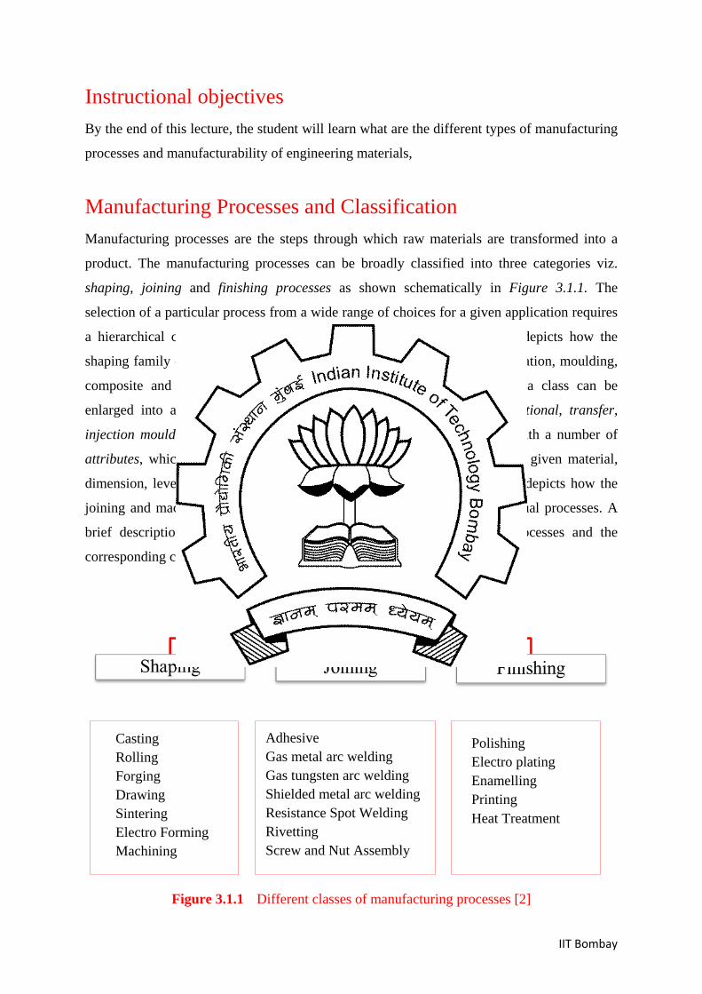
product. The manufacturing processes can be broadly classified into three categories viz.
shaping, joining and finishing processes as shown schematically in Figure 3.1.1. The
selection of a particular process from a wide range of choices for a given application requires
a hierarchical classification of the processes. For example, Figure 3.1.2 depicts how the
shaping family can be expanded in different classes such as casting, deformation, moulding,
composite and powder processing, and prototyping. Next, moulding as a class can be
enlarged into a number of member processes such as compression, rotational, transfer,
injection moulding, etc. Lastly, each member process can be identified with a number of
attributes, which would facilitate the selection of a member process for a given material,
dimension, level of requisite tolerances and so on. Similarly, Figure 3.1.3 depicts how the
joining and machining family can be expanded in different classes and actual processes. A
brief description of the three broad categories of the manufacturing processes and the
corresponding classifications are outlined in the following.
Figure 3.1.1 Different classes of manufacturing processes [2]
Casting Rolling Forging Drawing Sintering Electro Forming Machining
Adhesive Gas metal arc welding Gas tungsten arc welding Shielded metal arc welding Resistance Spot Welding Rivetting Screw and Nut Assembly
Polishing Electro plating Enamelling Printing Heat Treatment

IIT Bombay
Kingdom Family Class Member Attribute
Joining
Shaping
Finishing
Casting
Deformation
Moulding
Composite
Powder
Prototyping
Compression
Rotational
Transfer
Injection
Foam
Extrusion
Resin casting
Blow moulding
Thermoforming
Material Shape
Size range
Minimum section
Tolerance
Roughness Minimum Batch Size
Cost Model
Figure 3.1.2 Taxonomy of process with part of the shaping family [2]
Kingdom Family Class Member Attribute
Joining
Shaping
Finishing
Adhesives
Welding
Fasteners
Heat treatment
Paint/print
Coat
Polish
Texture
Braze
Solder
Arc
Gas
Hot Gas
Hot Bar
Electroplate
Anodize
Powder Coat
Figure 3.1.3 Taxonomy of processes with part of the joining and finishing family [2]
Processes
Processes
Material Joint geometry Size Range Thickness Relative cost... Supporting information
Purpose of treatment Coating thickness Surface hardness Relative cost...
IIT Bombay
Shaping Processes The shaping processes are referred to those that use a certain raw material and shape it to a
final part. Casting, moulding, powder material processing, primary and secondary material
forming, machining are typical example of shaping processes. A short exposure of different
shaping processes is enlisted below.
Casting Processes Most of the manufactured parts start its journey with casting process. In a typical casting
process, metal is first heated in a furnace until it melts and then the molten metal is poured
into a mold so that the liquid metal takes the shape of the mold cavity, which is the final
shape of the part. Once the liquid metal in the mold cavity solidifies, the mold is broken or
opened to take the final part out of the mold cavity. The metal casting process involves three
sequential steps –
• liquefying of metallic material by properly heating it in a suitable furnace,
• pouring of hot molten metal into a previously made colder mould cavity, • extraction of the solidified cast from the mould cavity
Though casting is one of the oldest manufacturing processes, it is still preferred over other
processes due to several advantages listed below:
• It is economical with very little wastage. Even the extra metal produced during
each casting can be re-melted and reused.
• It can produce parts with complex geometrical features such as internal cavities,
hollow sections with fair dimensional accuracy.
• Casting can be used to make very small to extremely large and complex parts.
• It is possible to cast metallic materials with very low to reasonably high melting
temperatures. Further, the mechanical properties of a cast are usually isotropic.
Classification of casting processes The casting processes can be classified into two broad categories – expendable mold casting
processes and permanent mold casting processes. In expendable mold casting processes, the
mold is usually broken to free the solidified cast whereas the mold can be reused in case of
permanent mold casting. The pattern used to prepare the molds can also be permanent and
IIT Bombay
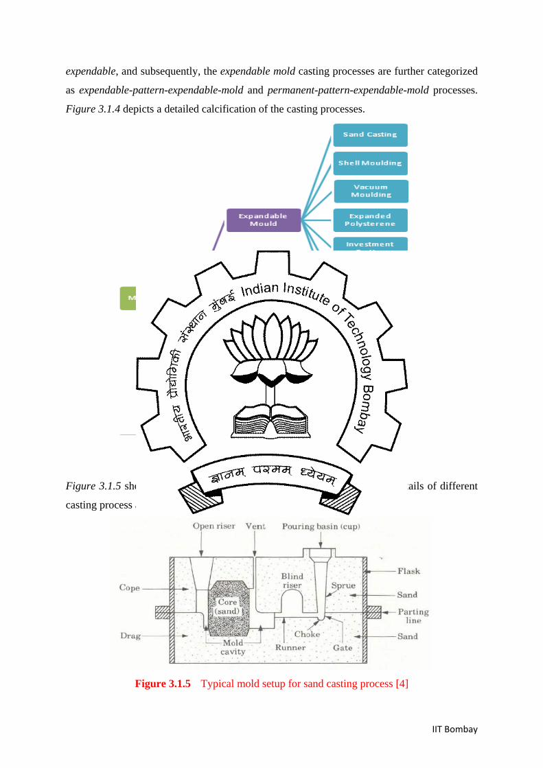
expendable, and subsequently, the expendable mold casting processes are further categorized
as expendable-pattern-expendable-mold and permanent-pattern-expendable-mold processes.
Figure 3.1.4 depicts a detailed calcification of the casting processes.
Figure 3.1.4 Classification of casting processes
Figure 3.1.5 shows a typical mold arrangement for sand casting. Further details of different
casting process are discussed in the subsequent lectures.
Figure 3.1.5 Typical mold setup for sand casting process [4]
IIT Bombay
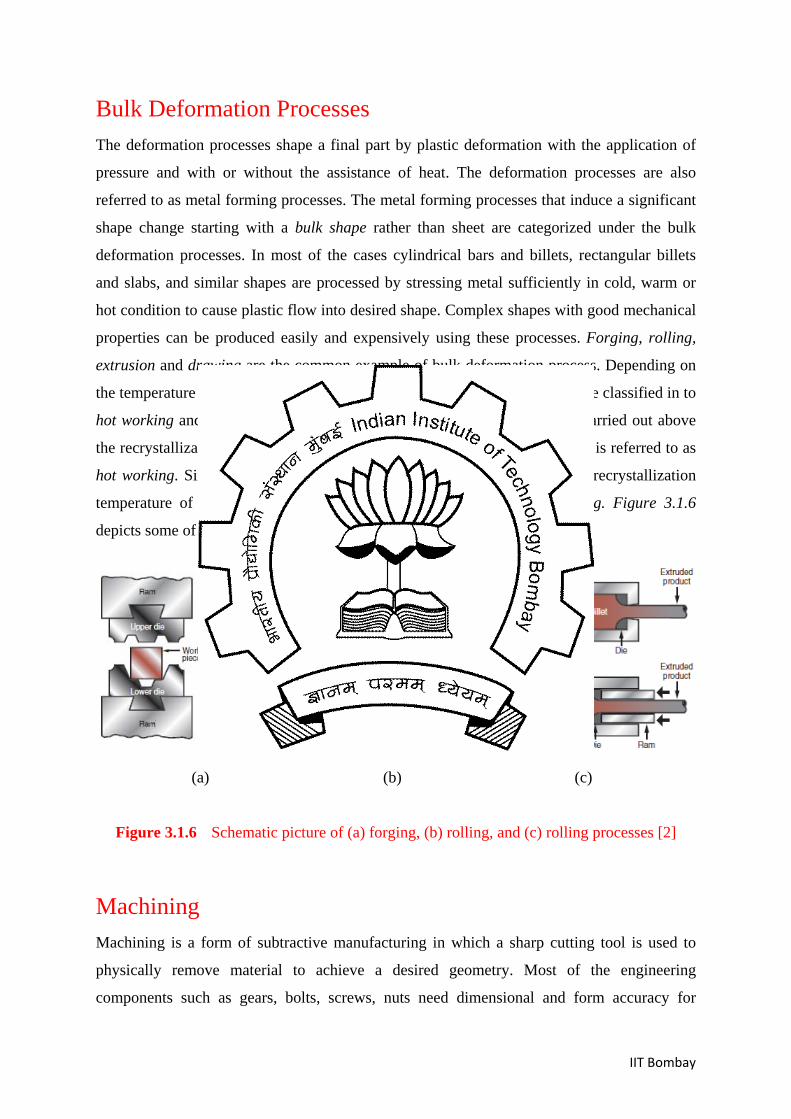
Bulk Deformation Processes The deformation processes shape a final part by plastic deformation with the application of
pressure and with or without the assistance of heat. The deformation processes are also
referred to as metal forming processes. The metal forming processes that induce a significant
shape change starting with a bulk shape rather than sheet are categorized under the bulk
deformation processes. In most of the cases cylindrical bars and billets, rectangular billets
and slabs, and similar shapes are processed by stressing metal sufficiently in cold, warm or
hot condition to cause plastic flow into desired shape. Complex shapes with good mechanical
properties can be produced easily and expensively using these processes. Forging, rolling,
extrusion and drawing are the common example of bulk deformation process. Depending on
the temperature at which the deformation is carried out, these processes can be classified in to
hot working and cold working processes. When the plastic deformation is carried out above
the recrystallization temperature of the material, the corresponding operation is referred to as
hot working. Similarly, when the plastic deformation is induced below the recrystallization
temperature of the material, the processes are referred to as cold working. Figure 3.1.6
depicts some of the bulk deformation processes in a schematic manner.
(a) (b) (c)
Figure 3.1.6 Schematic picture of (a) forging, (b) rolling, and (c) rolling processes [2]
Machining Machining is a form of subtractive manufacturing in which a sharp cutting tool is used to
physically remove material to achieve a desired geometry. Most of the engineering
components such as gears, bolts, screws, nuts need dimensional and form accuracy for
IIT Bombay
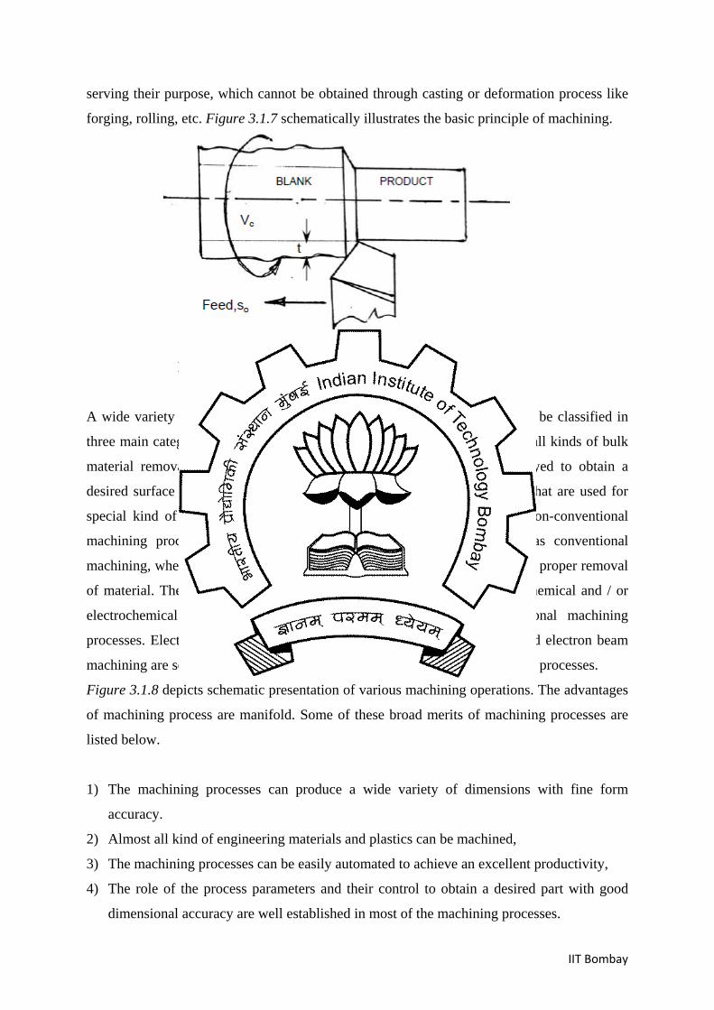
serving their purpose, which cannot be obtained through casting or deformation process like
forging, rolling, etc. Figure 3.1.7 schematically illustrates the basic principle of machining.
machining (turning)
Figure 3.1.7 Schematic illustration of machining process [4]
A wide variety of machining processes are available today that can broadly be classified in
three main categories – conventional machining processes that are used for all kinds of bulk
material removal operations, grinding processes that are primarily employed to obtain a
desired surface finish, non-conventional or advanced machining processes that are used for
special kind of material removal operations. As per the name suggests, non-conventional
machining processes do not follow the principle of relative hardness as conventional
machining, where the tool material must be harder than the work material for proper removal
of material. The processes that remove material by melting, evaporation, chemical and / or
electrochemical action etc. are generally referred to as non-conventional machining
processes. Electrodischarge machining, electrochemical machining, laser and electron beam
machining are some of the common examples of non-conventional machining processes.
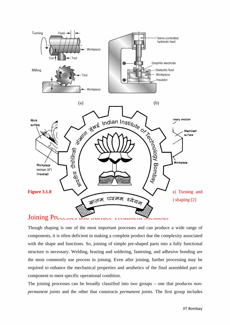
Figure 3.1.8 depicts schematic presentation of various machining operations. The advantages
of machining process are manifold. Some of these broad merits of machining processes are
listed below.
1) The machining processes can produce a wide variety of dimensions with fine form
accuracy.
2) Almost all kind of engineering materials and plastics can be machined,
3) The machining processes can be easily automated to achieve an excellent productivity,
4) The role of the process parameters and their control to obtain a desired part with good
dimensional accuracy are well established in most of the machining processes.
IIT Bombay
(a) (b)
(c) (d)
Figure 3.1.8 Schematic presentations of four machining processes – (a) Turning and
milling, b) electro discharge machining, c) surface grinding, d) shaping [2]
Joining Processes and Surface Treatment Methods Though shaping is one of the most important processes and can produce a wide range of
components, it is often deficient in making a complete product due the complexity associated
with the shape and functions. So, joining of simple pre-shaped parts into a fully functional
structure is necessary. Welding, brazing and soldering, fastening, and adhesive bonding are
the most commonly use process in joining. Even after joining, further processing may be
required to enhance the mechanical properties and aesthetics of the final assembled part or
component to meet specific operational condition.
The joining processes can be broadly classified into two groups – one that produces non-
permanent joints and the other that constructs permanent joints. The first group includes
IIT Bombay
some of the common mechanical joining processes such as screws and bolts, snap fits, shrink
fits etc. The permanent joining processes can be classified into four groups including
mechanical, solid state, liquid state, and liquid-solid state. The mechanical joining processes,
which are permanent in nature, include rivet, stitch, staple, and lap-seam. In principle, these
joints are heterogeneous in nature since no atomic bonding takes place along the original joint
interface.
Mechanical Joining Processes
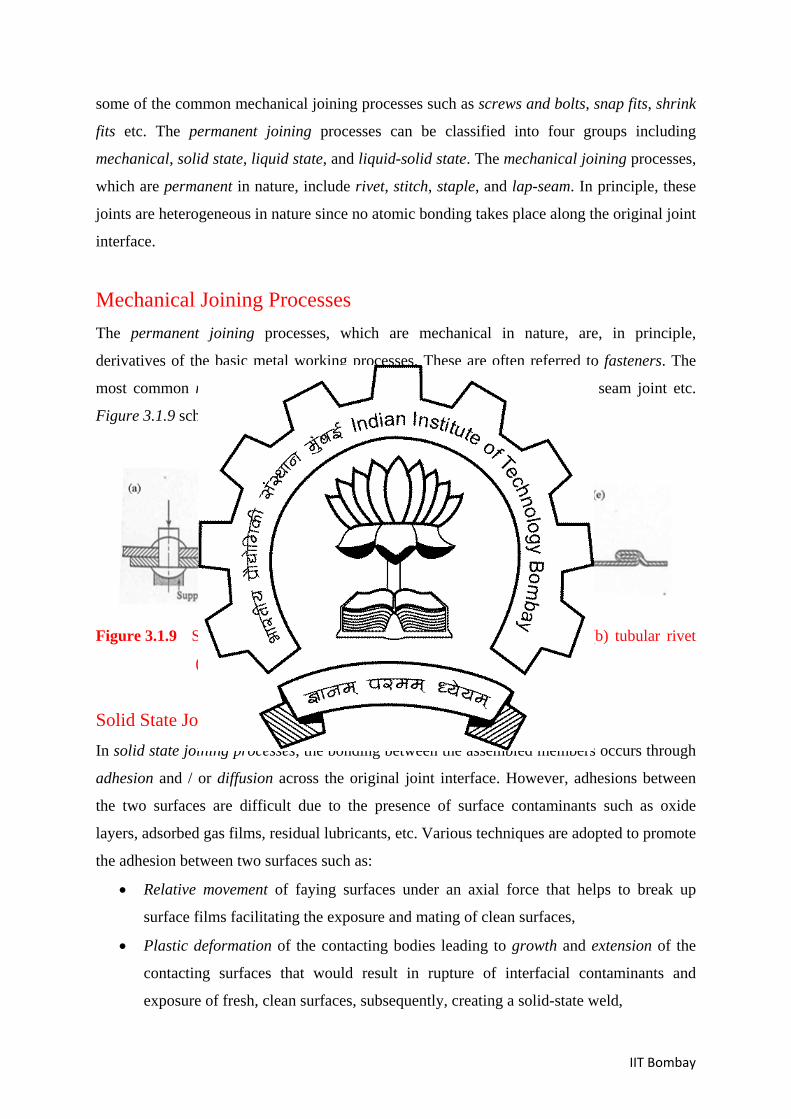
The permanent joining processes, which are mechanical in nature, are, in principle,
derivatives of the basic metal working processes. These are often referred to fasteners. The
most common mechanical joining methods are rivet, nut and bolts, staple, seam joint etc.
Figure 3.1.9 schematically depicts a number of mechanical joints.
Figure 3.1.9 Schematic presentation of five mechanical joints: (a) rivet, (b) tubular rivet
(c) blind rivet, (d) staple, (e) seam [1]
Solid State Joining Process In solid state joining processes, the bonding between the assembled members occurs through
adhesion and / or diffusion across the original joint interface. However, adhesions between
the two surfaces are difficult due to the presence of surface contaminants such as oxide
layers, adsorbed gas films, residual lubricants, etc. Various techniques are adopted to promote
the adhesion between two surfaces such as:
• Relative movement of faying surfaces under an axial force that helps to break up
surface films facilitating the exposure and mating of clean surfaces,
• Plastic deformation of the contacting bodies leading to growth and extension of the
contacting surfaces that would result in rupture of interfacial contaminants and
exposure of fresh, clean surfaces, subsequently, creating a solid-state weld,
IIT Bombay
• Softening of contacting interfaces by localized heating, applied externally or
generated in-process, to promote easy plastic deformation and / or inter-atomic
diffusion creating a solid-state bond.
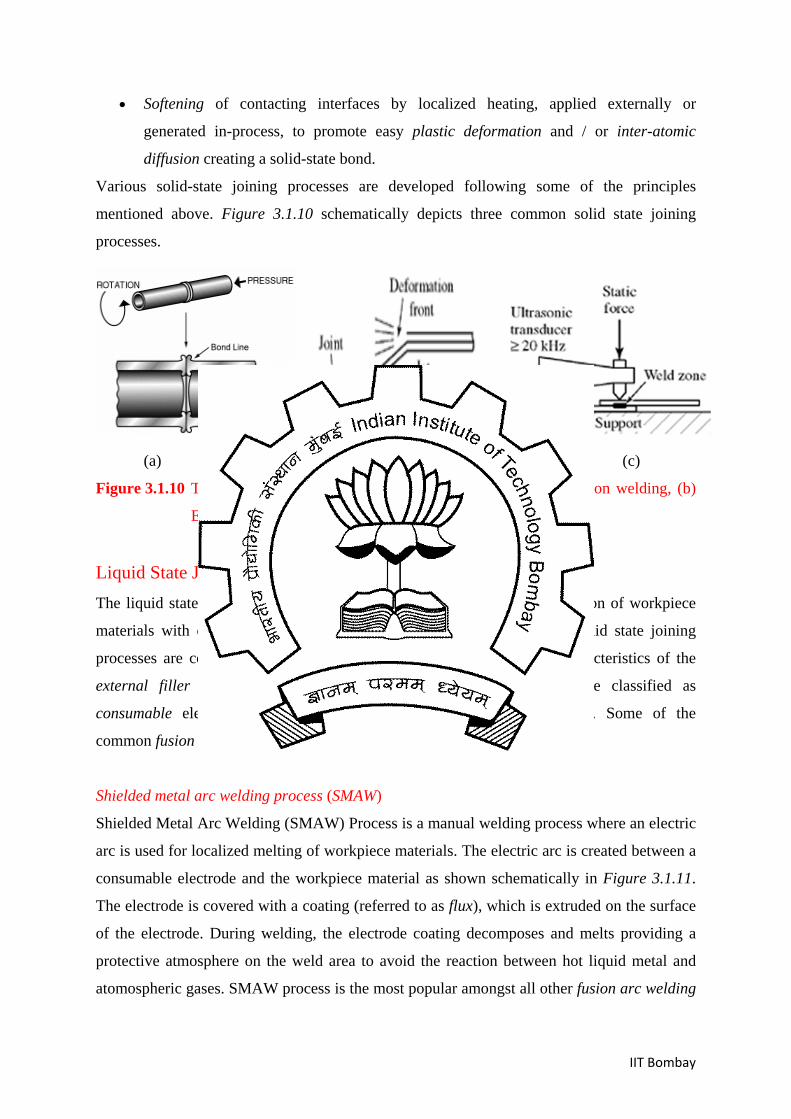
Various solid-state joining processes are developed following some of the principles
mentioned above. Figure 3.1.10 schematically depicts three common solid state joining
processes.
(a) (b) (c)
Figure 3.1.10 Three different types of solid state joining process; (a) Friction welding, (b)
Explosion welding, and (c) Ultrasonic welding [2]
Liquid State Joining Process
The liquid state joining processes involve localized melting and solidification of workpiece
materials with or without the addition of external filler material. The liquid state joining
processes are commonly referred to as fusion welding. Based on the characteristics of the
external filler (electrode) material, the welding processes can also be classified as
consumable electrode and non-consumable electrode welding processes. Some of the
common fusion welding processes are listed below.
Shielded metal arc welding process (SMAW)
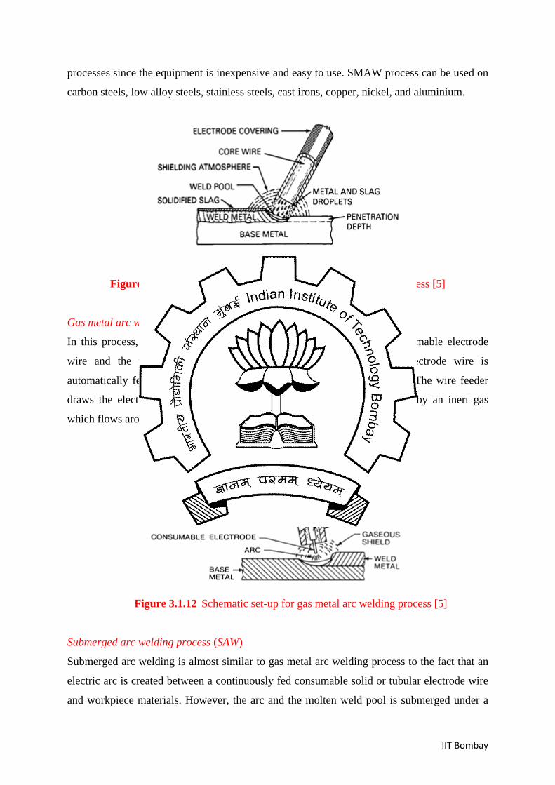
Shielded Metal Arc Welding (SMAW) Process is a manual welding process where an electric
arc is used for localized melting of workpiece materials. The electric arc is created between a
consumable electrode and the workpiece material as shown schematically in Figure 3.1.11.
The electrode is covered with a coating (referred to as flux), which is extruded on the surface
of the electrode. During welding, the electrode coating decomposes and melts providing a
protective atmosphere on the weld area to avoid the reaction between hot liquid metal and
atomospheric gases. SMAW process is the most popular amongst all other fusion arc welding
IIT Bombay
processes since the equipment is inexpensive and easy to use. SMAW process can be used on
carbon steels, low alloy steels, stainless steels, cast irons, copper, nickel, and aluminium.
Figure 3.1.11 Schematic set-up for shielded metal arc welding process [5]
Gas metal arc welding process (GMAW)
In this process, an electric arc is struck between a continuously fed consumable electrode
wire and the workpiece material as shown in Figure 3.1.12. The electrode wire is
automatically fed from a spool into the weld pool by a wire feed system. The wire feeder
draws the electrode through the welding torch. The shielding is supplied by an inert gas
which flows around the wire through a gas cap attached to the torch.
Figure 3.1.12 Schematic set-up for gas metal arc welding process [5]
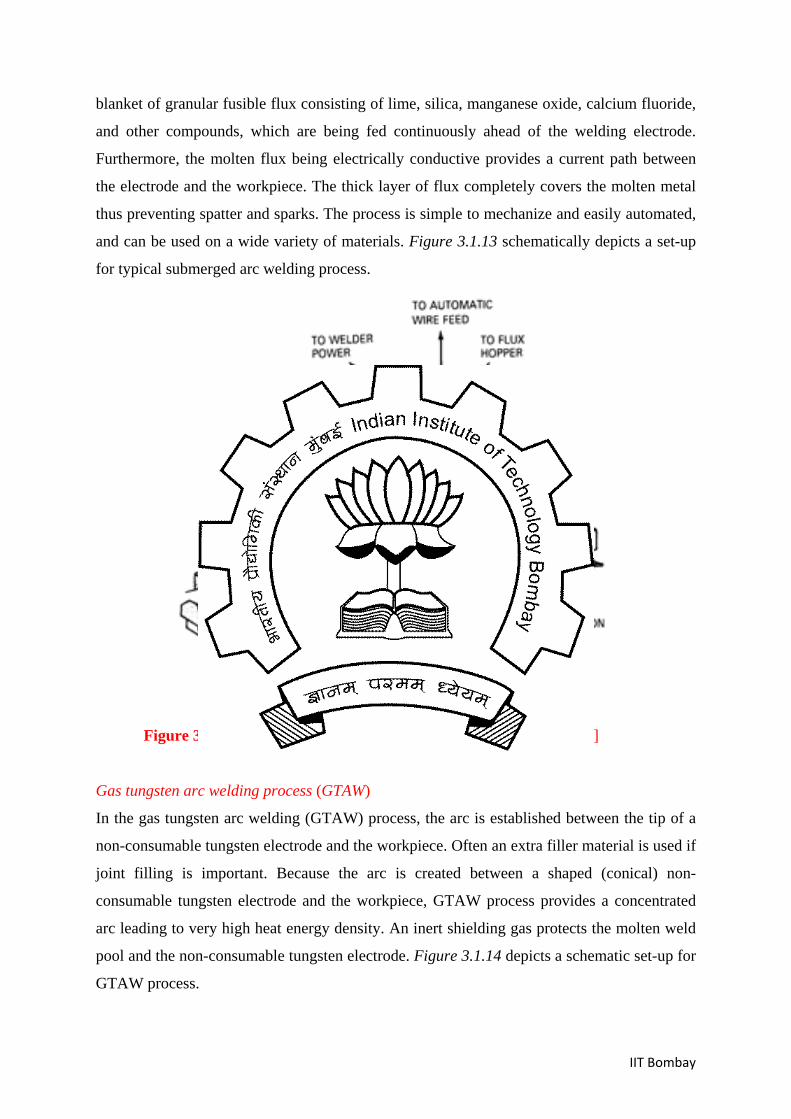
Submerged arc welding process (SAW)
Submerged arc welding is almost similar to gas metal arc welding process to the fact that an
electric arc is created between a continuously fed consumable solid or tubular electrode wire
and workpiece materials. However, the arc and the molten weld pool is submerged under a
IIT Bombay
blanket of granular fusible flux consisting of lime, silica, manganese oxide, calcium fluoride,
and other compounds, which are being fed continuously ahead of the welding electrode.
Furthermore, the molten flux being electrically conductive provides a current path between
the electrode and the workpiece. The thick layer of flux completely covers the molten metal
thus preventing spatter and sparks. The process is simple to mechanize and easily automated,
and can be used on a wide variety of materials. Figure 3.1.13 schematically depicts a set-up
for typical submerged arc welding process.
Figure 3.1.13 Schematic set-up for submerged arc welding process [5]
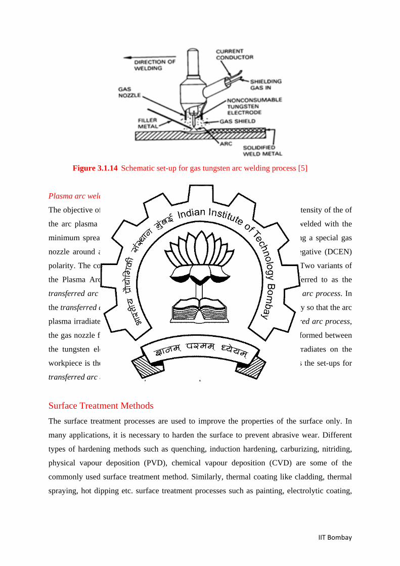
Gas tungsten arc welding process (GTAW)
In the gas tungsten arc welding (GTAW) process, the arc is established between the tip of a
non-consumable tungsten electrode and the workpiece. Often an extra filler material is used if
joint filling is important. Because the arc is created between a shaped (conical) non-
consumable tungsten electrode and the workpiece, GTAW process provides a concentrated
arc leading to very high heat energy density. An inert shielding gas protects the molten weld
pool and the non-consumable tungsten electrode. Figure 3.1.14 depicts a schematic set-up for
GTAW process.
IIT Bombay
Figure 3.1.14 Schematic set-up for gas tungsten arc welding process [5]
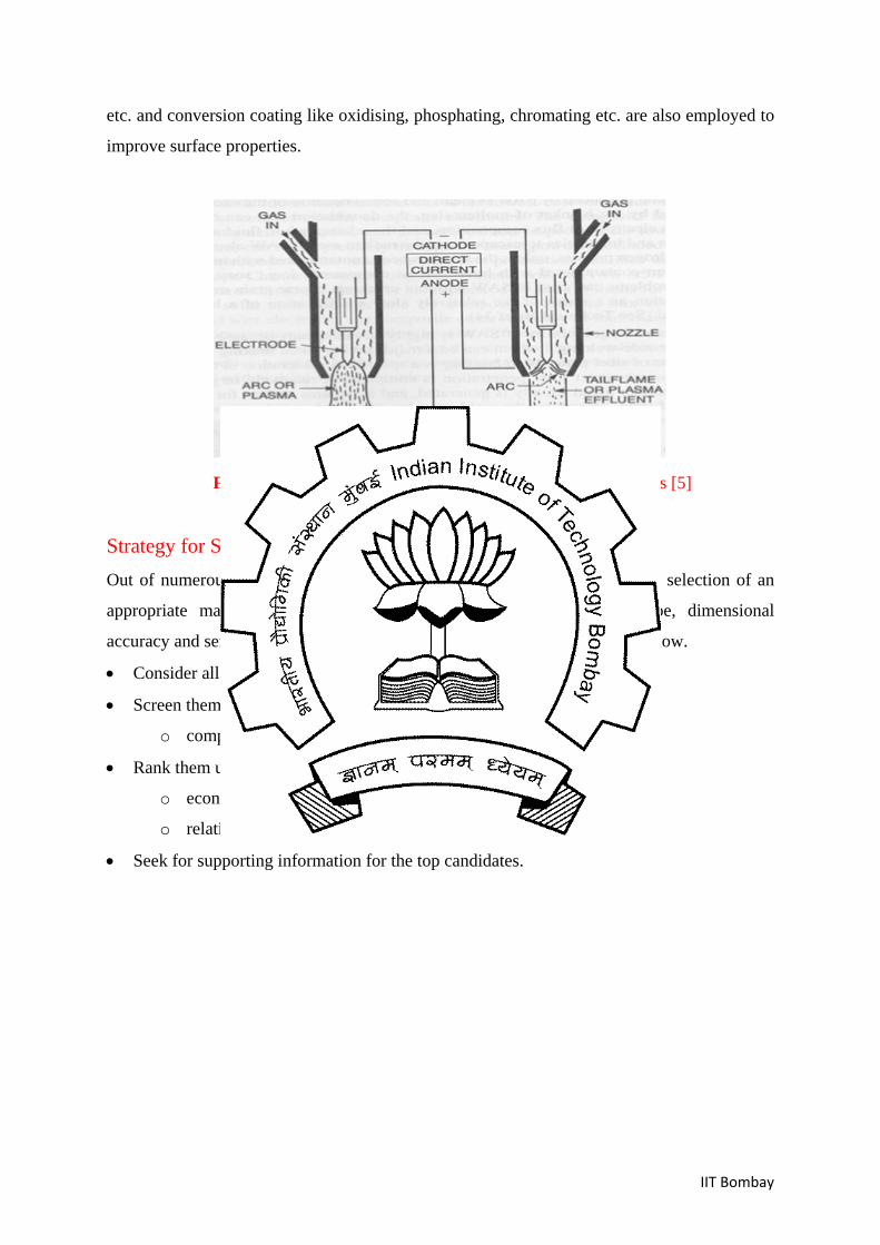
Plasma arc welding process (PAW)
The objective of the Plasma Arc Welding (PAW) process is to increase the intensity of the of
the arc plasma in a controlled manner such that greater thickness can be welded with the
minimum spread of the welding arc. This objective is achieved by providing a special gas
nozzle around a tungsten electrode operating on direct current electrode negative (DCEN)
polarity. The constricted plasma formed is highly ionized and concentrated. Two variants of
the Plasma Arc Welding (PAW) process are commonly used. One is referred to as the
transferred arc process and the second is referred to as the non-transferred arc process. In
the transferred arc process, the workpiece is connected to the negative polarity so that the arc
plasma irradiated on the workpiece has greater intensity. In the non-transferred arc process,
the gas nozzle forms part of the electric circuit and hence, the arc plasma is formed between
the tungsten electrode and the nozzle. The tail of the arc plasma that irradiates on the
workpiece is therefore of lesser intensity. Figure 3.1.15 schematically shows the set-ups for
transferred arc and non-transferred arc PAW processes.
Surface Treatment Methods The surface treatment processes are used to improve the properties of the surface only. In
many applications, it is necessary to harden the surface to prevent abrasive wear. Different
types of hardening methods such as quenching, induction hardening, carburizing, nitriding,
physical vapour deposition (PVD), chemical vapour deposition (CVD) are some of the
commonly used surface treatment method. Similarly, thermal coating like cladding, thermal
spraying, hot dipping etc. surface treatment processes such as painting, electrolytic coating,
IIT Bombay
etc. and conversion coating like oxidising, phosphating, chromating etc. are also employed to
improve surface properties.
Figure 3.1.15 Schematic set-up for plasma arc welding process [5]
Strategy for Selecting Proper Processes Out of numerous manufacturing processes only a few are listed above. The selection of an
appropriate manufacturing process for a given material, requisite shape, dimensional
accuracy and service is critical and broadly requires the following steps to follow.
• Consider all processes as probable candidates
• Screen them
o compatibility to material and / or shape and / or precision
• Rank them using objective
o economic batch size-ranges
o relative cost
• Seek for supporting information for the top candidates.
IIT Bombay
Exercise 1. Sort the following processes in the decreasing order of specific energy:
[i] Sheet metal forming [ii] Forging [iii] Machining [iv] Casting
2. Which of the following processes is suitable for components/assemblies with high
fatigue life?
[i] Machining [ii] Forging [iii] Casting [iv]Sheet metal forming
3. List two significant advantages of Investment Casting over sand casting.
4. Give examples of permanent and detachable type of mechanical fastener.
References 1. G Dieter, Engineering Design - a materials and processing approach, McGraw Hill,
NY, 2000.
2. M F Ashby, Material Selection in Mechanical Design, Butterworth-Heinemann, 1999.
3. John A. Schey, Introduction to Manufacturing Process.
4. A. Ghosh, A.Mallik, Manufacturing Science, Tata McGraw Hill,1997
5. Robert W. Messler,
Principles of Welding: Processes, Physics, Chemistry, and Metallurgy,
John Wiley &Sons, 1999