models srl, srl-c and srl-xt - goulds pumps · models srl, srl-c and srl-xt. note the in for ma...
TRANSCRIPT
© 1999 Goulds Pumps
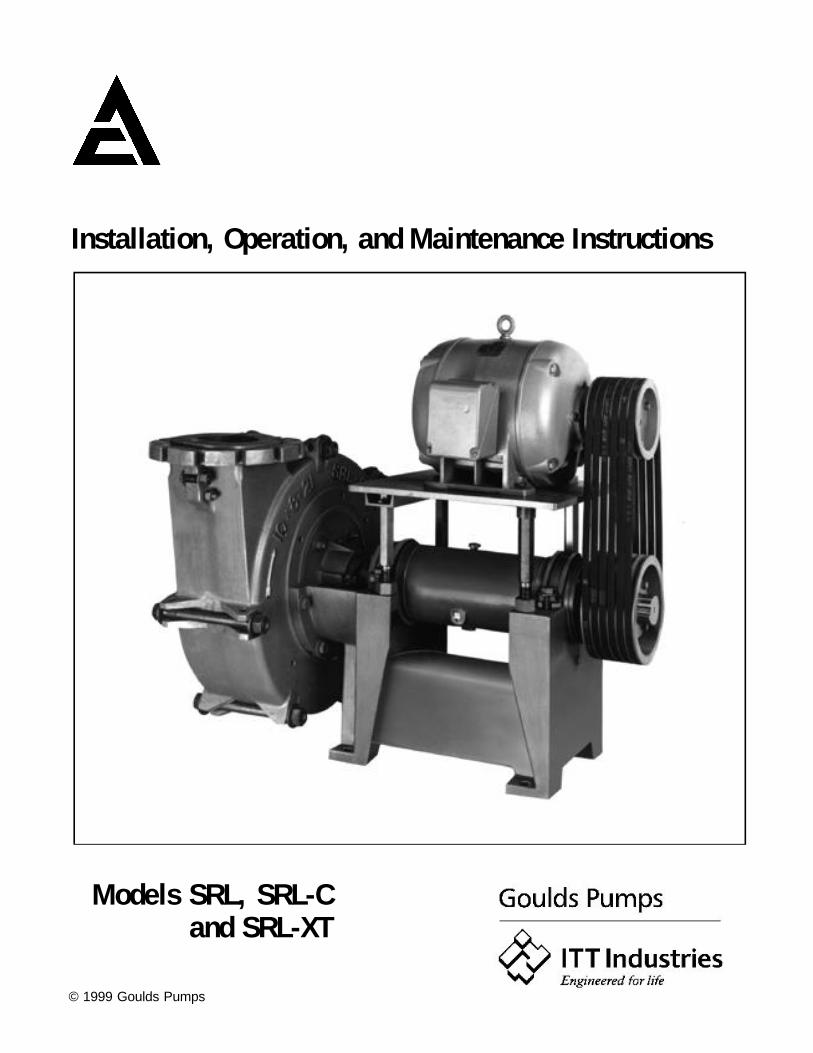
In stal la tion, Op er a tion, and Main te nance In struc tions
Models SRL, SRL-Cand SRL-XT

NOTE
The in for ma tion con tained in this book is in tended toas sist op er at ing per son nel by pro vid ing in for ma tionon the char ac ter is tics of the pur chased equip ment.
It does not re lieve the user of their re spon si bil ity ofus ing ac cepted en gi neer ing prac tices in the in stal la -tion, op er a tion, and main te nance of this equip ment.
Any fur ther ques tions, con tactITT In dus tries - Goulds Pumps.(519)824-7750

W A R N I N G
Your pump was care fully se lected, sized, man u fac tured and in spected with the ut most care to pro vide safeand re li able ser vice, at the best pos si ble ef fi ciency to suit your spe cific pump ing re qui re ments. In the in ter estof trou ble free pump op er a tion and safety of op er at ing per son nel, the fol low ing safety pre cau tion should bestrictly ad hered to.
1. READ AND FOL LOW CARE FULLY ALL RE COM MENCED PRO CE DURES, as de scribed inyour op er a tor’s man ual, for stor age, in stal la tion, start-up, op er a tion and main te nance of your pump andre lated aux il iary equip ment such as mo tor, vari able speed drive, gear re ducer, v-belt, cou pling, etc.
2. DRIVER RO TA TION MUST BE CHECKED be fore first start-up and be fore the v-belts are in stalledor the cou pling halves are con nected. Se vere equip ment dam age and in jury to per son nel may oc cur if thepump is driven in the op po site di rec tion to the ar row of ro ta tion cast on the pump cas ing.
3. DO NOT AL TER THE ORIG I NAL OP ER AT ING CON DI TIONS of the pump with out first con sult ingwith your lo cal ITT In dus tries - Goulds Pump rep re sen ta tive. The op er a tion of the pump at con di tions other thanthose for which it was de signed may re sult in equip ment dam age and in jury to op er a tors.
4. DO NOT OP ER ATE THE PUMP AT LOW OR ZERO FLOW CON DI TIONS. All op er at ingcon di tions which could cause the pumped liq uid to va por ize are dan ger ous, such as clogged suc tion anddis charge pip ing, shut-off suc tion and dis charge valves, etc. Va por pres sure build-up could cause thepump cas ing and sys tem pip ing to ex plode re sult ing in se vere equip ment dam age and per sonal in jury.
5. DO NOT USE HEAT TO AS SIST IN IM PEL LER RE MOVAL from the shaft when ser vic ing the pump. Heat can cause va por iza tion of fluid which may be trapped in the im pel ler hub re sult ing in an ex plo sion whichcould cause per sonal in jury and equip ment dam age.
6. DO NOT OP ER ATE THE PUMP WITH OUT PROP ERLY IN STALLED V-BELT OR COU PLINGGUARD. Fail ure to in stall guards may re sult in per sonal in jury.
S-1
IMPORTANT SAFETY NOTICE
To: Our Valued Customers
User safety is a major focus in the design of our products. Following the precautions outlined in this manual will minimize your risk of injury.
ITT Goulds pumps will provide safe, trouble-free service when properly installed, maintained, and operated.
Safe installation, operation, and maintenance of ITT Goulds Pumps equipment are an essential end user responsibility. This Pump Safety Manual identifies specific safety risks that must be considered at all times during product life. Understanding and adhering to these safety warnings is mandatory to ensure personnel, property, and/or the environment will not be harmed. Adherence to these warnings alone, however, is not sufficient — it is anticipated that the end user will also comply with industry and corporate safety standards. Identifying and eliminating unsafe installation, operating and maintenance practices is the responsibility of all individuals involved in the installation, operation, and maintenance of industrial equipment.
Please take the time to review and understand the safe installation, operation, and maintenance guidelines outlined in this Pump Safety Manual and the Instruction, Operation, and Maintenance (IOM) manual. Current manuals are available at www.gouldspumps.com/literature_ioms.html or by contacting your nearest Goulds Pumps sales representative.
These manuals must be read and understood before installation and start-up.
For additional information, contact your nearest Goulds Pumps sales representative or visit our Web site at www.gouldspumps.com.

S-2
SAFETY WARNINGS
Specific to pumping equipment, significant risks bear reinforcement above and beyond normal safety precautions.
WARNING
A pump is a pressure vessel with rotating parts that can be hazardous. Any pressure vessel can explode, rupture, or discharge its contents if sufficiently over pressurized causing death, personal injury, property damage, and/or damage to the environment. All necessary measures must be taken to ensure over pressurization does not occur.
WARNING
Operation of any pumping system with a blocked suction and discharge must be avoided in all cases. Operation, even for a brief period under these conditions, can cause superheating of enclosed pumpage and result in a violent explosion. All necessary measures must be taken by the end user to ensure this condition is avoided.
WARNING
The pump may handle hazardous and/or toxic fluids. Care must be taken to identify the contents of the pump and eliminate the possibility of exposure, particularly if hazardous and/or toxic. Potential hazards include, but are not limited to, high temperature, flammable, acidic, caustic, explosive, and other risks.
WARNING
Pumping equipment Instruction, Operation, and Maintenance manuals clearly identify accepted methods for disassembling pumping units. These methods must be adhered to. Specifically, applying heat to impellers and/or impeller retaining devices to aid in their removal is strictly forbidden. Trapped liquid can rapidly expand and result in a violent explosion and injury.
ITT Goulds Pumps will not accept responsibility for physical injury, damage, or delays caused by a failure to observe the instructions for installation, operation, and maintenance contained in this Pump Safety Manual or the current IOM available at www.gouldspumps.com/literature.
S-3
SAFETY
DEFINITIONS Throughout this manual the words WARNING, CAUTION, ELECTRICAL, and ATEX are used to indicate where special operator attention is required.
Observe all Cautions and Warnings highlighted in this Pump Safety Manual and the IOM provided with your equipment.
WARNING Indicates a hazardous situation which, if not avoided, could result in death or serious injury.
Example: Pump shall never be operated without coupling guard installed correctly.
CAUTION Indicates a hazardous situation which, if not avoided, could result in minor or moderate injury.
Example: Throttling flow from the suction side may cause cavitation and pump damage.
ELECTRICAL HAZARD
Indicates the possibility of electrical risks if directions are not followed.
Example: Lock out driver power to prevent electric shock, accidental start-up, and physical injury.
When installed in potentially explosive atmospheres, the instructions that follow the Ex symbol must be followed. Personal injury and/or equipment damage may occur if these instructions are not followed. If there is any question regarding these requirements or if the equipment is to be modified, please contact an ITT Goulds Pumps representative before proceeding.
Example: Improper impeller adjustment could cause contact between the rotating and stationary parts, resulting in a spark and heat generation.
S-4
GENERAL PRECAUTIONS
WARNING
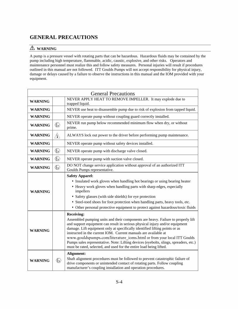
A pump is a pressure vessel with rotating parts that can be hazardous. Hazardous fluids may be contained by the pump including high temperature, flammable, acidic, caustic, explosive, and other risks. Operators and maintenance personnel must realize this and follow safety measures. Personal injuries will result if procedures outlined in this manual are not followed. ITT Goulds Pumps will not accept responsibility for physical injury, damage or delays caused by a failure to observe the instructions in this manual and the IOM provided with your equipment.
General Precautions
WARNING NEVER APPLY HEAT TO REMOVE IMPELLER. It may explode due to trapped liquid.
WARNING NEVER use heat to disassemble pump due to risk of explosion from tapped liquid.
WARNING NEVER operate pump without coupling guard correctly installed.
WARNING NEVER run pump below recommended minimum flow when dry, or without prime.
WARNING ALWAYS lock out power to the driver before performing pump maintenance.
WARNING NEVER operate pump without safety devices installed.
WARNING NEVER operate pump with discharge valve closed.
WARNING NEVER operate pump with suction valve closed.
WARNING DO NOT change service application without approval of an authorized ITT Goulds Pumps representative.
WARNING
Safety Apparel: Insulated work gloves when handling hot bearings or using bearing heater Heavy work gloves when handling parts with sharp edges, especially impellers
Safety glasses (with side shields) for eye protection Steel-toed shoes for foot protection when handling parts, heavy tools, etc. Other personal protective equipment to protect against hazardous/toxic fluids
WARNING
Receiving: Assembled pumping units and their components are heavy. Failure to properly lift and support equipment can result in serious physical injury and/or equipment damage. Lift equipment only at specifically identified lifting points or as instructed in the current IOM. Current manuals are available at www.gouldspumps.com/literature_ioms.html or from your local ITT Goulds Pumps sales representative. Note: Lifting devices (eyebolts, slings, spreaders, etc.) must be rated, selected, and used for the entire load being lifted.
WARNING
Alignment: Shaft alignment procedures must be followed to prevent catastrophic failure of drive components or unintended contact of rotating parts. Follow coupling manufacturer’s coupling installation and operation procedures.

S-5
General Precautions
WARNING Before beginning any alignment procedure, make sure driver power is locked out. Failure to lock out driver power will result in serious physical injury.
CAUTION
Piping: Never draw piping into place by forcing at the flanged connections of the pump. This may impose dangerous strains on the unit and cause misalignment between pump and driver. Pipe strain will adversely effect the operation of the pump resulting in physical injury and damage to the equipment.
WARNING Flanged Connections: Use only fasteners of the proper size and material.
WARNING Replace all corroded fasteners.
WARNING Ensure all fasteners are properly tightened and there are no missing fasteners.
WARNING Startup and Operation: When installing in a potentially explosive environment, please ensure that the motor is properly certified.
WARNING Operating pump in reverse rotation may result in contact of metal parts, heat generation, and breach of containment.
WARNING Lock out driver power to prevent accidental start-up and physical injury.
WARNING The impeller clearance setting procedure must be followed. Improperly setting the clearance or not following any of the proper procedures can result in sparks, unexpected heat generation and equipment damage.
WARNING If using a cartridge mechanical seal, the centering clips must be installed and set screws loosened prior to setting impeller clearance. Failure to do so could result in sparks, heat generation, and mechanical seal damage.
WARNING The coupling used in an ATEX classified environment must be properly certified and must be constructed from a non-sparking material.
WARNING Never operate a pump without coupling guard properly installed. Personal injury will occur if pump is run without coupling guard.
WARNING Make sure to properly lubricate the bearings. Failure to do so may result in excess heat generation, sparks, and / or premature failure.
CAUTION The mechanical seal used in an ATEX classified environment must be properly certified. Prior to start up, ensure all points of potential leakage of process fluid to the work environment are closed.
CAUTION Never operate the pump without liquid supplied to mechanical seal. Running a mechanical seal dry, even for a few seconds, can cause seal damage and must be avoided. Physical injury can occur if mechanical seal fails.
WARNING Never attempt to replace packing until the driver is properly locked out and the coupling spacer is removed.
WARNING Dynamic seals are not allowed in an ATEX classified environment.
WARNING DO NOT operate pump below minimum rated flows or with suction and/or discharge valve closed. These conditions may create an explosive hazard due to vaporization of pumpage and can quickly lead to pump failure and physical injury.
S-6
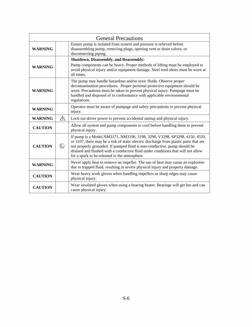
General Precautions
WARNING Ensure pump is isolated from system and pressure is relieved before disassembling pump, removing plugs, opening vent or drain valves, or disconnecting piping.
WARNING
Shutdown, Disassembly, and Reassembly: Pump components can be heavy. Proper methods of lifting must be employed to avoid physical injury and/or equipment damage. Steel toed shoes must be worn at all times.
WARNING
The pump may handle hazardous and/or toxic fluids. Observe proper decontamination procedures. Proper personal protective equipment should be worn. Precautions must be taken to prevent physical injury. Pumpage must be handled and disposed of in conformance with applicable environmental regulations.
WARNING Operator must be aware of pumpage and safety precautions to prevent physical injury.
WARNING Lock out driver power to prevent accidental startup and physical injury.
CAUTION Allow all system and pump components to cool before handling them to prevent physical injury.
CAUTION
If pump is a Model NM3171, NM3196, 3198, 3298, V3298, SP3298, 4150, 4550, or 3107, there may be a risk of static electric discharge from plastic parts that are not properly grounded. If pumped fluid is non-conductive, pump should be drained and flushed with a conductive fluid under conditions that will not allow for a spark to be released to the atmosphere.
WARNING Never apply heat to remove an impeller. The use of heat may cause an explosion due to trapped fluid, resulting in severe physical injury and property damage.
CAUTION Wear heavy work gloves when handling impellers as sharp edges may cause physical injury.
CAUTION Wear insulated gloves when using a bearing heater. Bearings will get hot and can cause physical injury.
S-7
ATEX CONSIDERATIONS and INTENDED USE Special care must be taken in potentially explosive environments to ensure that the equipment is properly maintained. This includes but is not limited to:
1. Monitoring the pump frame and liquid end temperature. 2. Maintaining proper bearing lubrication. 3. Ensuring that the pump is operated in the intended hydraulic range.
The ATEX conformance is only applicable when the pump unit is operated within its intended use. Operating, installing or maintaining the pump unit in any way that is not covered in the Instruction, Operation, and Maintenance manual (IOM) can cause serious personal injury or damage to the equipment. This includes any modification to the equipment or use of parts not provided by ITT Goulds Pumps. If there is any question regarding the intended use of the equipment, please contact an ITT Goulds representative before proceeding. Current IOMs are available at www.gouldspumps.com/literature_ioms.html or from your local ITT Goulds Pumps Sales representative.
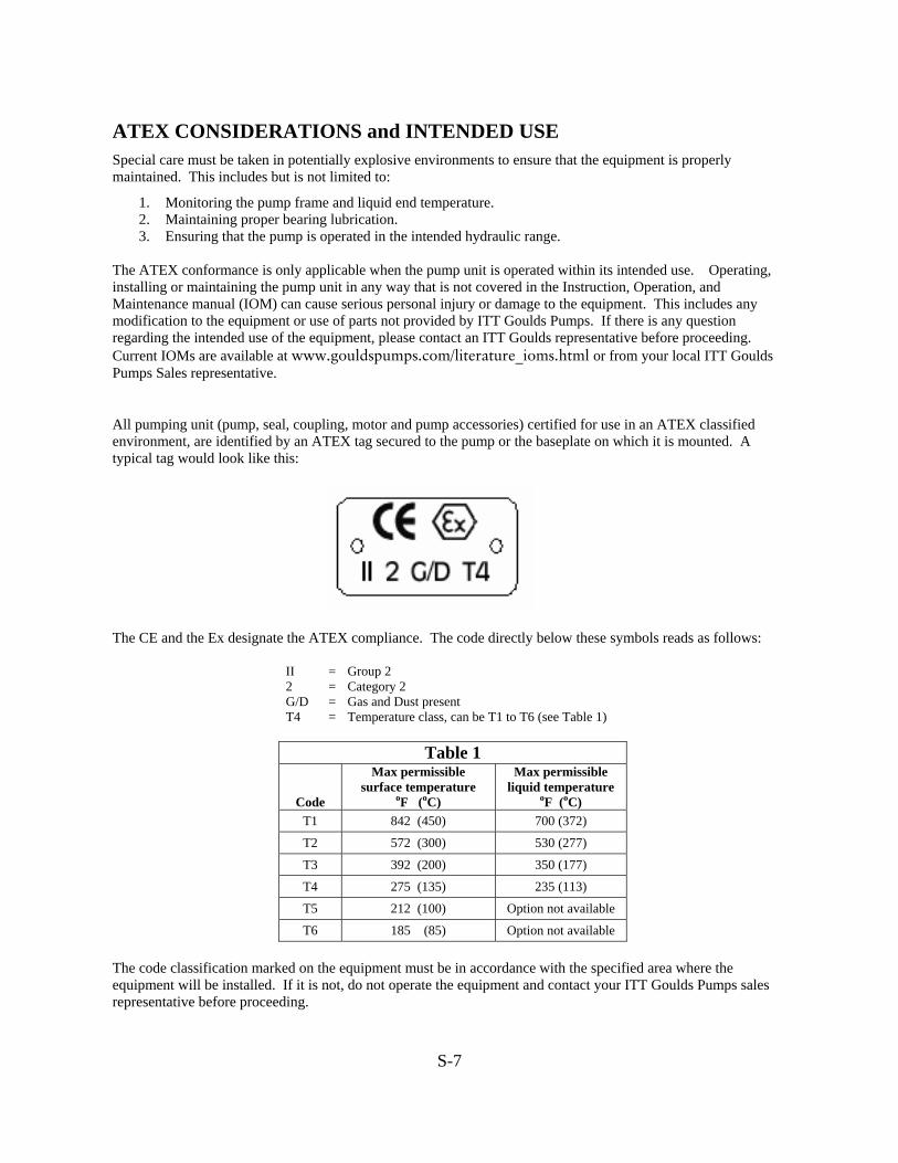
All pumping unit (pump, seal, coupling, motor and pump accessories) certified for use in an ATEX classified environment, are identified by an ATEX tag secured to the pump or the baseplate on which it is mounted. A typical tag would look like this:
The CE and the Ex designate the ATEX compliance. The code directly below these symbols reads as follows:
II = Group 2 2 = Category 2 G/D = Gas and Dust present T4 = Temperature class, can be T1 to T6 (see Table 1)
Table 1
Code
Max permissible surface temperature
oF (oC)
Max permissible liquid temperature
oF (oC) T1 842 (450) 700 (372)
T2 572 (300) 530 (277)
T3 392 (200) 350 (177)
T4 275 (135) 235 (113)
T5 212 (100) Option not available
T6 185 (85) Option not available
The code classification marked on the equipment must be in accordance with the specified area where the equipment will be installed. If it is not, do not operate the equipment and contact your ITT Goulds Pumps sales representative before proceeding.
S-8
PARTS
The use of genuine Goulds parts will provide the safest and most reliable operation of your pump. ITT Goulds Pumps ISO certification and quality control procedures ensure the parts are manufactured to the highest quality and safety levels. Please contact your local Goulds representative for details on genuine Goulds parts.


The law requires that the belt drives and/or couplings on thisequipment be covered by SAFETY GUARDS while inoperation. Such guards must be provided by the owner if notspecifically contracted to ITT Industries - Goulds Pump.
TABLE of CONTENTSPage
General Information 1 & 2
Start-up and Operation 3
Locating Trouble 4
Dismantling and Re-Assembly Procedure:Photos 52x2x10 SRL 6 & 73x3x10 SRL, 5x5x14 SRL, 6x6x15 SRL, 8 & 93x3x10 SRL-C and 5x4x14 SRL-C8x6x18 SRL-C & 10x8x21 SRL-C 10 & 1112x10x25 SRL-C 12 & 1314x12x29 SRL-C 14 & 1516x14x34 SRL-C 16 & 1720x18x40 SRL-C 18 & 196x6x21 SRL-XT 20 & 218x8x25 SRL-XT 22 & 2310x10x28 SRL-XT 24 & 2514x12x36 SRL-XT 26 & 27
Rigid Liner 28

Page 1
GENERAL INFORMATION
INTRODUCTIONThis man ual is fur nished to ac quaint you with the eas i est andmost prac ti cal way to in stall, op er ate and main tain this pump.Keep it handy for fu ture ref er ence. Ad di tional in for ma tion canbe ob tained from the near est ITT In dus tries - Goulds Pumpsales of fice or cer ti fied dealer. The stan dards of the Hy drau licIn sti tute are an ex cel lent source for sup ple men tary ad vice onthe sub ject of in stal la tion, op er a tion and main te nance of pumps. To keep the unit at top ef fi ciency, cor rect pro ce dures forin stall ing and main tain ing must be fol lowed. The ITTIn dus tries - Goulds Pump ser vice or ga ni za tion can help in stallthis equip ment cor rectly so that max i mum ma chine life can beob tained with a min i mum of down time.
PUMP IDENTIFICATIONThe size and type designation of ITT Industries - Goulds Pumprubber-lined pumps includes the suction and dischargediameters and the nominal impeller diameter. For example, a12x10x25 SRL-C pump has a 12" suction, a 10" discharge anda 25" diameter closed impeller.
INSPECTIONRECEIVING PUMP
Check pump for damage and material shortages after arrival.Prompt reporting to the carrier’s agent, with notations made onthe freight bill, will expedite satisfactory adjustment by thecarrier.
2. Unload and handle the unit carefully.
NOTE: HOLES ON CAS ING LUGS ARE USED TOLIFT CAS ING HALVES ONLY. DO NOT USEFOR LIFT ING ENTIRE UNIT.
TEMPORARY STORAGEIf the pump is not to be installed and operated soon afterarrival, store it in a cool, dry and dark place, ideally 50°—70° F (10°- 21° C) with a maximum of 100° F (38° C). If storedbelow 32° F (0° C), some rubber products may become stiffand should be warmed before being placed in service. Do notstore near electrical equipment which may generate ozone or inareas of known high ozone. Avoid direct or reflected sunlight.Certain insect and rodents thrive on rubber products soadequate protection should be provided. Rubber should not bestored in areas of high or low humidity. Oils, solvents,corrosive liquids and fumes could also adversely affect therubber.
Rotate the shaft periodically to coat the bearings with lubricantand to retard oxidation and corrosion.
FOUNDATIONFOUNDATION
The foundation should be sufficiently substantial to absorb anyvibration, and to form a permanent rigid support for the pump.A concrete foundation, with foundation bolts of the proper sizegrouted in place to drawing dimensions, is recommended.
MOUNTING OF PUMPThe foundation surface will support the pump with sole-platesunder the frame at the foundation bolts. The sole-plates can beset in a puddle of grout and should be leveled in all directions,and in relation to each other. This will ensure a minimumamount of shimming necessary to completely level the pump.
Tighten the foundation bolts evenly and recheck for all roundlevelness of the pump.
PIPINGNote that piping should not be connected to pump until unit has been set per instructions and grouted in.
1. Support piping close to, but independently of pump.
2. Keep piping as straight as possible, with few or no bendsand fittings.
3. Remove burrs, sharp edges, ream pipe cuts, and make joints air tight.
4. Do not “spring” pipes to make connection. Strain must notbe transmitted to pump.
SUCTION PIPE1. The suction pipe should be as short as possible, containing a minimum number of fittings. It should be so arranged that onesection may be readily removed to allow the dismantling of thesuction half casing. Victaulic or similar type couplings arerecommended for this section of the pipe to facilitatedismantling. The suction pipe should slope upwards to thepump nozzle.
2. Suction line inlet in the sump must be flooded at all times,even if it necessary to install the pumps so that a suction lift isinvolved. The pump must never be throttled by the use of avalve on the suction side of the pump. It is advisable to have ashut-off valve in the suction line so that the pump can beisolated while repairs are being made, but this valve shouldnever be used to control the capacity of the pump by throttling.
DISCHARGE PIPEOn long horizontal runs, it is desirable to maintain as even agrade as feasible. Avoid high spots, such as loops, which will collect air and throttle the system or lead to erratic pumpingor surging.
Page 2
GENERAL INFORMATION
LUBRICATIONAll horizontal SRL, SRL-C, and SRL-XT pumps are designed for oil lubricationwith anti-friction bearings. Before starting the pump flush the cylinder or frameliner with oil to remove any grit or dirt that may have entered the bearing housingduring shipment or erection. Then refill with the proper lubricant to the operativelevel as shown by a line of the oil sight glass.
Experience shows that oils meeting the following specifications will providesatisfactory lubrication. These oils can be furnished by all major oil companies. It isthe responsibility of the oil vendor to supply a suitable lubricant.
1) Saybolt viscosity at 100° F . . . . . . . . . . . . . . . 300 SSU - 650 SSU2) Saybolt viscosity at 210° F . . . . . . . . . . . . . . . . 50 SSU - 70 SSU3) Viscosity index . . . . . . . . . . . . . . . . . . . . . . . . . . . 90 - 1004) API gravity . . . . . . . . . . . . . . . . . . . . . . . . . . . . . . 28 - 305) Pour point . . . . . . . . . . . . . . . . . . . . . . . . . . . . -5° F - 25° F6) Flash point . . . . . . . . . . . . . . . . . . . . . . . . . . 430° F - 485° F7) Additives . . . . . . . . . . . . . . . . . . . . rust and oxidation inhibitors
The oil should be well refined, premium to heavy duty type (API), filtered mineral oil with non-foaming characteristics. It must be free from water, sediment, resin,soaps, acid and fillers of any kind. It should also contain a protective agent against rust and wear. An SAE-20-30 grade with the above characteristics isrecommended.
In installations with moderate temperature changes, humidity and dirt, the first oil change should be made after approximately 160 hours of operation. The oilshould be inspected at this time to determine the operation period before the nextoil change. Oil change periods may be increased up to 2000-4000 hours based onan 8000 hour year. Check the oil frequently for moisture, dirt or signs of“breakdown.”
The bearings are also protected with a grease seal located in the bearing cover. Agrease fitting is provided to fill cavity in the bearing cover with grease to preventforeign matter from entering the bearing housing.
We recommend the use of a 30°-300° F (-1°-149° C) temperature range grease ofabout 1500 SSU at 100° F (38° C) (base oil viscosity). The grease should be ofhigh quality, have shear stability, controlled adhesiveness and rust preventiveadditives.
CAUTIONDO NOT OVER OIL as this causes the bearings to run hot and failprematurely. The maximum desirable operating temperature for ball bearingsis 180° F (82° C). Should the temperature of the bearing frame exceed 180° F(82° C) (measured by thermometer), shut down pump to determine the cause.
Oils from different supplier should not be mixed.
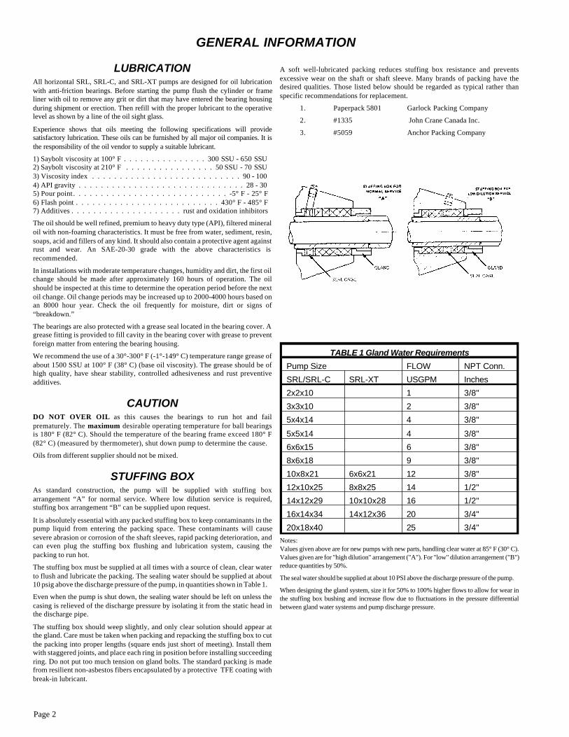
STUFFING BOXAs standard construction, the pump will be supplied with stuffing boxarrangement “A” for normal service. Where low dilution service is required,stuffing box arrangement “B” can be supplied upon request.
It is absolutely essential with any packed stuffing box to keep contaminants in thepump liquid from entering the packing space. These contaminants will causesevere abrasion or corrosion of the shaft sleeves, rapid packing deterioration, andcan even plug the stuffing box flushing and lubrication system, causing thepacking to run hot.
The stuffing box must be supplied at all times with a source of clean, clear waterto flush and lubricate the packing. The sealing water should be supplied at about10 psig above the discharge pressure of the pump, in quantities shown in Table 1.
Even when the pump is shut down, the sealing water should be left on unless thecasing is relieved of the discharge pressure by isolating it from the static head inthe discharge pipe.
The stuffing box should weep slightly, and only clear solution should appear atthe gland. Care must be taken when packing and repacking the stuffing box to cutthe packing into proper lengths (square ends just short of meeting). Install themwith staggered joints, and place each ring in position before installing succeedingring. Do not put too much tension on gland bolts. The standard packing is madefrom resilient non-asbestos fibers encapsulated by a protective TFE coating withbreak-in lubricant.
A soft well-lubricated packing reduces stuffing box resistance and preventsexcessive wear on the shaft or shaft sleeve. Many brands of packing have thedesired qualities. Those listed below should be regarded as typical rather thanspecific recommendations for replacement.
1. Paperpack 5801 Garlock Packing Company
2. #1335 John Crane Canada Inc.
3. #5059 Anchor Packing Company
TABLE 1 Gland Water Requirements
Pump Size FLOW NPT Conn.
SRL/SRL-C SRL-XT USGPM Inches
2x2x10 1 3/8"
3x3x10 2 3/8"
5x4x14 4 3/8"
5x5x14 4 3/8"
6x6x15 6 3/8"
8x6x18 9 3/8"
10x8x21 6x6x21 12 3/8"
12x10x25 8x8x25 14 1/2"
14x12x29 10x10x28 16 1/2"
16x14x34 14x12x36 20 3/4"
20x18x40 25 3/4"Notes:Values given above are for new pumps with new parts, handling clear water at 85° F (30° C).Values given are for "high dilution" arrangement ("A"). For "low" dilution arrangement ("B") reduce quantities by 50%.
The seal water should be supplied at about 10 PSI above the discharge pressure of the pump.
When designing the gland system, size it for 50% to 100% higher flows to allow for wear inthe stuffing box bushing and increase flow due to fluctuations in the pressure differentialbetween gland water systems and pump discharge pressure.
Page 3
START-UP and OPERATION
STARTING THE PUMP 1. Check the direction of rotation of the driver. All SRL,SRL-C, SRL-XT, and SRL-XT pumps are designed forclockwise rotation (looking at the pump from the drive end). The impellers are held in place by right-hand threads. Incorrectrotation of the motor could cause the impeller to unscrew andjam against the casing liner, causing severe damage to the pump.
2. Driver and driven sheaves must be carefully lined up paralleland square. On V-Belt applications, tension of the belts should beadjusted periodically. It is very important belts be tensionedproperly per belt manufacturer’s recommendations. Undertensioned belts will cause belts to slip and over tensioned beltswill put undue forces on shaft and bearings. Mount coupling orbelt guard before starting pump.
NOTE: SAFETY GUARDS ARE MAN DA TORY FORTHIS EQUIP MENT. IT IS THE OWNER’SRESPON SI BIL ITY TO PRO VIDE, AND/ORALTER AND MAIN TAIN THESE GUARDS INACCOR DANCE WITH LOCAL SAFETY CODEREG U LA TIONS.
3. Turn the shaft by hand to be sure that no solid material isimpeding the impeller from rotating. This is particularlyimportant if the pump has been idle with slurry in the casing.Solids could settle so that the shaft could not be turned by hand,and the casing would have to be opened to clear out the solids.
4. Turn on the sealing water supply to the stuffing box, perinstructions on page 2.
5. Slowly admit slurry into pump, and prime the unit byflooding the entire casing.
6. If a valve is installed in the discharge line, it should beclosed as the initial load on the motor will be greatly reduced in this way.
7. Start motor.
8. Open discharge valve slowly.
9. Check stuffing box to ensure there is a slight leakage ofclear water. The gland bolts should not be much more thanfinger tight for proper operation.
10. Check sump to be sure suction pipe is well flooded withslurry.
IMPELLER CLEARANCE To obtain proper performance from the pump and increase parts wear life, it is recommended that the clearance between theimpeller and suction side liner/wear plate be adjustedperiodically. For instructions on the method of adjustingclearance, refer to individual instructions for dismantling andreassembly—pages 6 thru 27.
MAINTENANCE TIMETABLE
EVERY MONTH Check bearing temperature with a thermometer, not by hand. Ifbearings are running hot, it may be the result of too much (ortoo little) lubricant. If changing the lubricant does not correctthe condition, disassemble and inspect the bearings.
EVERY 3 MONTHS Drain oil and flush oil reservoir and bearings. Refill to properlevel with recommended grade of lubricant (see page 2).
EVERY 6 MONTHS Check the packing and replace if necessary. Use the packinggrade recommended.
Check shaft sleeve for scoring. Scoring accelerates packingwear, so do not install new packing on scored sleeves.
Check alignment of pump. Shim up units if necessary. Ifmisalignment recurs frequently, inspect the entire pipingsystem. Unbolt piping at suction and discharge flanges to see ifit springs away, thereby indicating strain on the casing. Inspectall piping supports for soundness and effective support of load.
EVERY YEAR Remove the rotating element. Inspect thoroughly for wear, andorder replacement parts if necessary.
Remove any deposit or scaling. Clean out stuffing box piping.
Page 4
NO LIQUID OR NOT ENOUGH LIQUIDDELIVERED
1. Lack of prime.Fill pump and suction completely with slurry. Check forvapor bind.
2. Speed too low.Check whether motor is wired correctly and receiving fullvoltage across each phase. If frequency is too low, motor mayhave an open phase. Check V-Belt tension. Check sheavediam e ters.
3. Discharge head too high. Check pipe fric tion losses. Larger piping may correct condi tion. Are valves wide open?
4. Suction lift too high. Check for pipe fric tion losses as static lift may be too great.Measure with mercury column or vacuum gauge while pumpoper ates. If static lift is too high, liquid to be pumped must beraised or pump lowered.
5. Impeller completely or partially plugged. Dismantle pump and clean impeller.
6. Obstruction at inlet. Check and remove.
7. Defective packing Replace packing and sleeve if badly worn.
NOT ENOUGH PRESSURE 8. Speed too low. See item 2.
9. Obstruction in liquid passages. Dismantle pump and inspect passages of impeller and casing.Remove obstruc tion.
INCONSISTENT OPERATION 10. Incomplete priming. Free pump, pip ing and valves of all air. If high points insuc tion line pre vent this, they need cor rect ing. See Suc tionPip ing on page 2.
11. Suction lift too high. See item 4.
12. Stuffing box too tight. Release gland pres sure. Tighten reason ably. If sealing waterdoes not flow while pump oper ates, replace packing. Checkshaft or shaft sleeve for scoring, replace if neces sary. Alwayshave slight leakage from packed stuffing box.
13. Casing distorted by excessive strains from suction ordischarge piping.
Examine pump for rubbing between impeller and casing;replace damaged parts.
14. Shaft bent due to thermal distortion, damage duringoverhauling, or improper assembly of rotating element.
Check run-out by turning between lathe centers. Total run-outshould not exceed .002" on all pumps.
15. Mechanical failure of critical pump parts. Check bear ings, and impeller for damage. Any irreg u larity inthese parts will cause a drag on the shaft.
MOTOR OVERLOADS16. Liquid heavier (in specific gravity) than allowed for. Use larger driver. Consult pump manu fac turer forrecom mended size. Test liquid for specific gravity.
17. Speed may be too high (Brake HP of pump varies as thecube of the speed); therefore, any increase in speed means considerable increase in power demand.
Check voltage on motor.
HOW TO REMEDY PUMP TROUBLES
• FIND TROUBLE IN HEADING BELOW. . . . . . . .
• CHECK CAUSES . . . . . . . . . . . . . . . . . . . .
• FOLLOW SUGGESTED CURES . . . . . . . . . . .
EXAMPLENO LIQUID DELIVERED
1. Lack of prime. Fill pump and suction completelywith slurry. Check for vapor bind.
LOCATING TABLES
Page 5
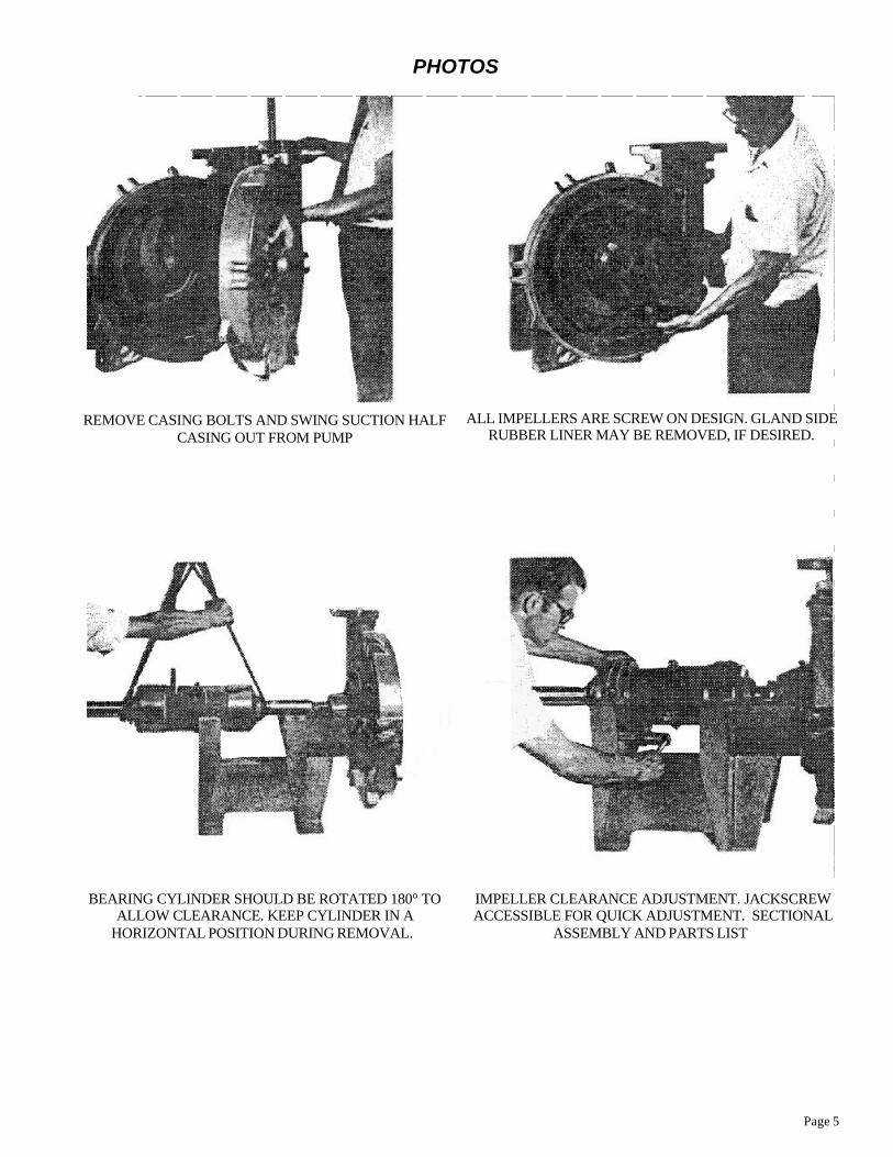
REMOVE CASING BOLTS AND SWING SUCTION HALFCASING OUT FROM PUMP
ALL IMPELLERS ARE SCREW ON DESIGN. GLAND SIDE RUBBER LINER MAY BE REMOVED, IF DESIRED.
BEARING CYLINDER SHOULD BE ROTATED 180° TOALLOW CLEARANCE. KEEP CYLINDER IN A
HORIZONTAL POSITION DURING REMOVAL.
IMPELLER CLEARANCE ADJUSTMENT. JACKSCREWACCESSIBLE FOR QUICK ADJUSTMENT. SECTIONAL
ASSEMBLY AND PARTS LIST
PHOTOS
Page 6
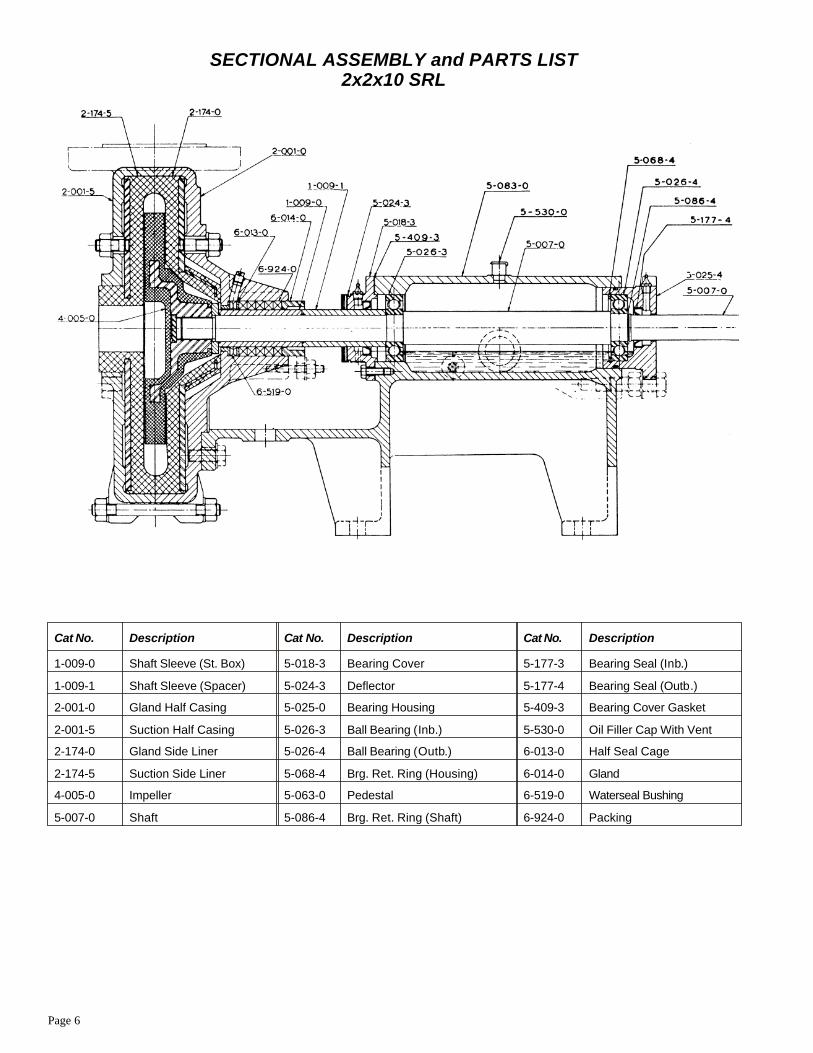
SECTIONAL ASSEMBLY and PARTS LIST2x2x10 SRL
Cat No. Description Cat No. Description Cat No. Description
1-009-0 Shaft Sleeve (St. Box) 5-018-3 Bearing Cover 5-177-3 Bearing Seal (Inb.)
1-009-1 Shaft Sleeve (Spacer) 5-024-3 Deflector 5-177-4 Bearing Seal (Outb.)
2-001-0 Gland Half Casing 5-025-0 Bearing Housing 5-409-3 Bearing Cover Gasket
2-001-5 Suction Half Casing 5-026-3 Ball Bearing (Inb.) 5-530-0 Oil Filler Cap With Vent
2-174-0 Gland Side Liner 5-026-4 Ball Bearing (Outb.) 6-013-0 Half Seal Cage
2-174-5 Suction Side Liner 5-068-4 Brg. Ret. Ring (Housing) 6-014-0 Gland
4-005-0 Impeller 5-063-0 Pedestal 6-519-0 Waterseal Bushing
5-007-0 Shaft 5-086-4 Brg. Ret. Ring (Shaft) 6-924-0 Packing
Page 7
2x2x10 SRL
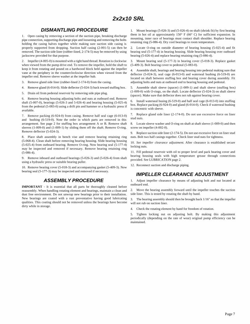
DISMANTLING PROCEDURE1. Open casing by removing a section of the suction pipe, breaking dischargepipe connection, supporting discharge pipe and loosening and removing the boltsholding the casing halves together while making sure suction side casing isproperly supported from dropping. Suction half casing (2-001-5) can then beremoved. The suction side liner (rubber-lined, 2-174-5) may be removed by using jackscrew provided for that purpose.
2. Impeller (4-005-0) is mounted with a right hand thread. Rotation is clockwise when viewed from the pump drive end. To remove the impeller, hold the shaft tokeep it from rotating and pound on a hardwood block held against the impellervane at the periphery in the counterclockwise direction when viewed from theimpeller end. Remove sleeve washer at the impeller hub.
3. Remove gland side liner (rubber-lined 2-174-0) from the casing.
4. Remove gland (6-014-0). Slide deflector (5-024-3) back toward stuffing box.
5. Drain oil from pedestal reservoir by removing side pipe plug.
6. Remove bearing housing adjusting bolts and nuts at outboard end. Removeshaft (5-007-0), bearings (5-026-3 and 5-026-4) and bearing housing (5-025-4)from the pedestal (5-083-0) using a drift pin and hammer or a hydraulic press ifavailable.
7. Remove packing (6-924-0) from casing. Remove half seal cage (6-013-0)and bushing (6-519-0). Note the order in which parts are removed in thisarrangement. See page 2 for stuffing box arrangement A or B. Remove shaftsleeves (1-009-0) and (1-009-1) by sliding them off the shaft. Remove O-ring.Remove deflector (5-024-3).
8. Place shaft assembly in bench vise and remove bearing retaining ring(5-068-4). Clean shaft before removing bearing housing. Slide bearing housing(5-025-4) from outboard bearing. Remove O-ring. Now bearing seal (5-177-4)may be inspected and removed if necessary. Remove bearing retaining ring(5-086-4).
9. Remove inboard and outboard bearings (5-026-3) and (5-026-4) from shaftusing a hydraulic press or suitable bearing puller.
10. Remove bearing cover (5-018-3) and accompanying gasket (5-409-3). Nowbearing seal (5-177-3) may be inspected and removed if necessary.
ASSEMBLY PROCEDURE IMPORTANT - It is essential that all parts be thoroughly cleaned beforereassembly. When handling rotating element and bearings, maintain a clean anddust free environment. Do not unwrap new bearings prior to their installation.New bearings are coated with a rust preventative having good lubricatingqualities. This coating should not be removed unless the bearings have becomedirty while in storage.
1. Mount bearings (5-026-3) and (5-026-4) on shaft (shrink fit) by first heatingthem in hot oil at approximately 150° F (66° C) for sufficient expansion. Inmounting, inner race of bearings must contact shaft shoulder. Replace bearingretaining ring (5-086-4). Dry cool bearings to room temperature.
2. Locate O-ring on outside diameter of bearing housing (5-025-4) and fitbearing seal (5-177-4) in bearing housing. Slide bearing housing over outboardbearing (5-026-4) and replace bearing retaining ring (5-086-4).
3. Mount bearing seal (5-177-3) in bearing cover (5-018-3). Replace gasket(5-409-3). Bolt bearing cover to pedestal (5-083-0).
4. Assemble shaft, bearings and bearing housing into pedestal making sure thatdeflector (5-024-3), seal cage (6-013-0) and waterseal bushing (6-519-0) arelocated on shaft between stuffing box and bearing cover during assembly. Fitadjusting bolts and nuts at outboard end to bearing housing and pedestal.
5. Assemble shaft sleeve (spacer) (1-009-1) and shaft sleeve (stuffing box)(1-009-0) with O-rings, on the shaft. Locate deflector (5-024-3) on shaft sleeve(spacer). Make sure that deflector does not rub against bearing cover.
6. Install waterseal busing (6-519-0) and half seal cage (6-013-0) into stuffingbox. Replace packing (6-924-0) and gland (6-014-0). Check if waterseal bushingis concentric with sleeve.
7. Replace gland side liner (2-174-0). Do not use excessive force on linerstud nuts.
8. Locate sleeve washer and O-ring on shaft at shaft sleeve (1-009-0) and thenscrew on impeller (4-002-0).
9. Replace suction side liner (2-174-5). Do not use excessive force on liner studnuts. Bolt two half casings together. Check liner stud nuts for tightness.
10. See impeller clearance adjustment. After clearance is established securelocking nuts.
11. Fill pedestal reservoir with oil to proper level and pack bearing cover andbearing housing seals with high temperature grease through connectionsprovided. See LUBRICATION page 2.
12. Reconnect suction and discharge piping.
IMPELLER CLEARANCE ADJUSTMENT 1. Adjust impeller clearance by means of adjusting bolt and nut located atoutboard end.
2. Move the bearing assembly forward until the impeller touches the suctionside liner. This is tested by rotating the shaft by hand.
3. The bearing assembly should then be brought back 1/16" so that the impellerwill not rub on suction liner.
4. Check the rotating element by hand for freedom of rotation.
5. Tighten locking nut on adjusting bolt. By making this adjustmentperiodically (depending on the rate of wear) original pump efficiency can bemaintained.
Page 8
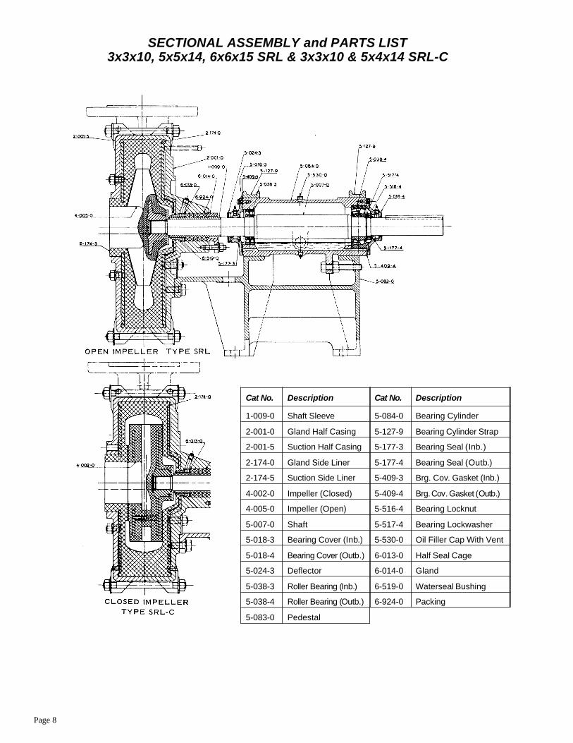
Cat No. Description Cat No. Description
1-009-0 Shaft Sleeve 5-084-0 Bearing Cylinder
2-001-0 Gland Half Casing 5-127-9 Bearing Cylinder Strap
2-001-5 Suction Half Casing 5-177-3 Bearing Seal (Inb.)
2-174-0 Gland Side Liner 5-177-4 Bearing Seal (Outb.)
2-174-5 Suction Side Liner 5-409-3 Brg. Cov. Gasket (Inb.)
4-002-0 Impeller (Closed) 5-409-4 Brg. Cov. Gasket (Outb.)
4-005-0 Impeller (Open) 5-516-4 Bearing Locknut
5-007-0 Shaft 5-517-4 Bearing Lockwasher
5-018-3 Bearing Cover (Inb.) 5-530-0 Oil Filler Cap With Vent
5-018-4 Bearing Cover (Outb.) 6-013-0 Half Seal Cage
5-024-3 Deflector 6-014-0 Gland
5-038-3 Roller Bearing (Inb.) 6-519-0 Waterseal Bushing
5-038-4 Roller Bearing (Outb.) 6-924-0 Packing
5-083-0 Pedestal
SECTIONAL ASSEMBLY and PARTS LIST3x3x10, 5x5x14, 6x6x15 SRL & 3x3x10 & 5x4x14 SRL-C
Page 9
3x3x10, 5x5x14, 6x6x15 SRL3x3x10 & 5x4x14 SRL-C
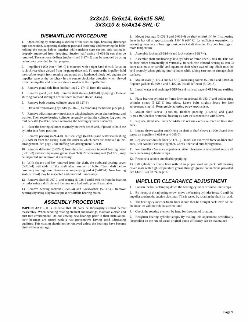
DISMANTLING PROCEDURE1. Open casing by removing a section of the suction pipe, breaking dischargepipe connection, supporting discharge pipe and loosening and removing the boltsholding the casing halves together while making sure suction side casing isproperly supported from dropping. Suction half casing (2-001-5) can then beremoved. The suction side liner (rubber-lined 2-174-5) may be removed by usingjackscrews provided for that purpose.
2. Impeller (4-002-0 or 4-005-0) is mounted with a right hand thread. Rotationis clockwise when viewed from the pump drive end. To remove the impeller, holdthe shaft to keep it from rotating and pound on a hardwood block held against theimpeller vane at the periphery in the counterclockwise direction when viewedfrom the impeller end. Remove sleeve washer at the impeller hub.
3. Remove gland side liner (rubber-lined 2-174-0) from the casing.
4. Remove gland (6-014-0). Remove shaft sleeve (1-009-0) by prying it loose at stuffing box and sliding it off the shaft. Remove sleeve O-ring.
5. Remove both bearing cylinder straps (5-127-9).
6. Drain oil from bearing cylinder (5-084-0) by removing the bottom pipe plug.
7. Remove adjusting screw mechanism which includes cotter pin, castle nut and washer. Then rotate bearing cylinder assembly so that the cylinder lug does notfoul pedestal (5-083-0) when removing the bearing cylinder assembly.
8. Place the bearing cylinder assembly on work bench and, if possible, hold thecylinder in a fixed position.
9. Remove packing (6-924-0), half seal cage (6-013-0) and waterseal bushing(6-6-519-0) from the casing. Note the order in which parts are removed in thisarrangement. See page 2 for stuffing box arrangement A or B.
10. Remove deflector (5-024-3) from the shaft. Remove inboard bearing cover(5-018-3) and accompanying gasket (5-409-3). Now bearing seal (5-177-3) maybe inspected and removed if necessary.
11. With sheave and key removed from the shaft, the outboard bearing cover(5-018-4) will slide off the shaft after removal of bolts. Clean shaft beforeremoving bearing cover. Remove accompanying gasket (5-409-4). Now bearingseal (5-177-4) may be inspected and removed if necessary.
12. Remove shaft (5-007-0) and bearing (5-038-3 and 5-038-4) from the bearingcylinder using a drift pin and hammer or a hydraulic press if available.
13. Remove bearing locknut (5-516-4) and lockwasher (5-517-4). Removebearings by using a hydraulic press or suitable bearing puller.
ASSEMBLY PROCEDUREIMPORTANT - It is essential that all parts be thoroughly cleaned beforereassembly. When handling rotating element and bearings, maintain a clean anddust-free environment. Do not unwrap new bearings prior to their installation.New bearings are coated with a rust preventative having good lubricatingqualities. This coating should not be removed unless the bearings have becomedirty while in storage.
1. Mount bearings (5-038-3 and 5-038-4) on shaft (shrink fit) by first heatingthem in hot oil at approximately 150° F (66° C) for sufficient expansion. Inmounting inner race of bearings must contact shaft shoulder. Dry cool bearings toroom temperature.
2. Assemble locknut (5-516-4) and lockwasher (5-517-4).
3. Assemble shaft and bearings into cylinder or frame liner (5-084-0). This canbe done either horizontally or vertically. In each case inboard bearing (5-038-3)outer race must be parallel and square to shaft when assembling. Shaft must beheld securely when guiding into cylinder while taking care not to damage shaftsurfaces.
4. Mount seals (5-177-4 and 5-177-3) in bearing covers (5-018-4 and 5-018-3).Replace gaskets (5-409-4 and 5-409-3). Install deflector (5-024-3).
5. Install water seal bushing (6-519-0) and half seal cage (6-013-0) into stuffingbox.
6. Place bearing cylinder or frame liner on pedestal (5-083-0) and bolt bearingcylinder straps (5-127-9) into place. Leave bolts slightly loose for lateradjustment, step 11. Reassemble adjusting screw mechanism.
7. Mount shaft sleeve (1-009-0). Replace packing (6-924-0) and gland(6-014-0). Check if waterseal bushing (5-519-0) is concentric with sleeve.
8. Replace gland side liner (2-174-0). Do not use excessive force on liner studnuts.
9. Locate sleeve washer and O-ring on shaft at shaft sleeve (1-009-0) and thenscrew on impeller (4-002-0 or 4-005-0).
10. Replace suction side liner (2-174-5). Do not use excessive force on liner studnuts. Bolt two half casings together. Check liner stud nuts for tightness.
11. See impeller clearance adjustment. After clearance is established secure allbolts on bearing cylinder straps.
12. Reconnect suction and discharge piping.
13. Fill cylinder or frame liner with oil to proper level and pack both bearingcover seals with high temperature grease through grease connections provided.See LUBRICATION, page 2.
IMPELLER CLEARANCE ADJUSTMENT1. Loosen the bolts clamping down the bearing cylinder or frame liner straps.
2. By means of the adjusting screw, move the bearing cylinder forward until theimpeller touches the suction side liner. This is tested by rotating the shaft by hand.
3. The bearing cylinder or frame liner should then be brought back 1/16" so thatthe impeller will not rub on suction liner.
4. Check the rotating element by hand for freedom of rotation.
5. Retighten bearing cylinder straps. By making this adjustment periodically(depending on the rate of wear) original pump efficiency can be maintained
.

Page 10
Cat No. Description Cat No. Description Cat No. Description
1-009-0 Shaft Sleeve 5-018-4 Bearing Cover (Outb.) 5-409-3 Bearing Cover Gasket (Inb.)
2-001-0 Gland Half Casing 5-024-3 Deflector 5-409-4 Bearing Cover Gasket (Outb.)
2-001-5 Suction Half Casing 5-038-3 Roller Bearing (Inb.) 5-516-4 Bearing Locknut
2-046-5 Casing Sideplate 5-038-4 Roller Bearing (Outb.) 5-517-4 Bearing Lockwasher
2-174-0 Gland Side Liner 5-083-0 Pedestal 5-530-0 Oil Filler Cap With Vent
2-174-5 Suction Side Liner 5-084-0 Bearing Cylinder 6-013-0 Half Seal Cage
4-002-0 Impeller 5-127-9 Bearing Cylinder Strap 6-014-0 Gland
5-007-0 Shaft 5-177-3 Bearing Seal (Inb.) 6-519-0 Waterseal Bushing
5-018-3 Bearing Cover (Inb.) 5-177-4 Bearing Seal (Outb.) 6-924-0 Packing
SECTIONAL ASSEMBLY and PARTS LIST8x6x18 and 10x8x21 SRL-C

Page 11
8x6x18 and 10x8x21 SRL-C
DISMANTLING PROCEDURE1. Open casing by removing a section of the suction pipe, breaking dischargepipe connection, supporting discharge pipe and loosening and removing the boltsholding the casing halves together while making sure suction side casing isproperly supported from dropping. Suction half casing (2-001-5) can then beremoved. Remove casing sideplate (2-046-5). The suction side liner (rubber-lined 2-174-5) may be removed by using jackscrews provided for that purpose.
2. Impeller (4-002-0) is mounted with a right hand thread. Rotation is clockwise when viewed from the pump drive end. To remove the impeller, hold the shaft tokeep it from rotating and pound on a hardwood block held against the impellervane at the periphery in the counterclockwise direction when viewed from theimpeller end.
3. Remove gland side liner (rubber-lined 2-174-0) from the casing.
4. Remove gland (6-014-0). Remove shaft sleeve (1-009-0) by prying it loose at stuffing box and sliding it off the shaft. Remove sleeve O-ring.
5. Remove both bearing cylinder straps (5-127-9).
6. Drain oil from bearing cylinder (5-084-0) by removing the bottom pipe plug.
7. Remove adjusting screw mechanism which includes cotter pin, castle nut and washer. Then rotate bearing cylinder assembly so that the cylinder lug does notfoul pedestal (5-083-0) when removing the bearing cylinder assembly.
8. Place the bearing cylinder assembly on work bench and, if possible, hold thecylinder in a fixed position.
9. Remove packing (6-924-0), half seal cage (6-013-0) and waterseal bushing(6-519-0) from the casing. Note the order in which parts are removed in thisarrangement. See page 2 for stuffing box arrangement A or B.
10. Remove deflector (5-024-3) from the shaft. Remove inboard bearing cover(5-018-3) and accompanying gasket (5-409-3). Now bearing seal (5-177-3) maybe inspected and removed if necessary.
11. With sheave and key removed from the shaft, the outboard bearing cover(5-018-4) will slide off the shaft after removal of bolts. Clean shaft beforeremoving bearing cover. Remove accompanying gasket (5-409-4). Now bearingseal (5-177-4) may be inspected and removed if necessary.
12. Remove shaft (5-007-0) and bearings (5-038-3 and 5-038-4) from thebearing cylinder using a drift pin and hammer or a hydraulic press if available.
13. Remove bearing lockout (5-516-4) and lockwasher (5-517-4). Removebearings by using a hydraulic press or suitable bearing puller.
ASSEMBLY PROCEDUREIMPORTANT - It is essential that all parts be thoroughly cleaned beforereassembly. When handling rotating element and bearings, maintain a clean anddust-free environment. Do not unwrap new bearings prior to their installation.New bearings are coated with a rust preventative having good lubricatingqualities. This coating should not be removed unless the bearings have becomedirty while in storage.
1. Mount bearings (5-038-3 and 5-038-4) on shaft (shrink fit) by first heatingthem in hot oil at approximately 150° F (66° C) for sufficient expansion. Inmounting inner race of bearings must contact shaft shoulder. Dry cool bearings toroom temperature.
2. Assemble locknut (5-516-4) and lockwasher (5-517-4).
3. Assemble shaft and bearings into cylinder or frame liner (5-084-0). This canbe done either horizontally or vertically. In each case inboard bearing (5-038-3)outer race must be parallel and square to shaft when assembling. Shaft must beheld securely when guiding into cylinder while taking care not to damage shaftsurfaces.
4. Mount seals (5-177-4 and 5-177-3) in bearing covers (5-018-4 and 5-018-3).Replace gaskets (5-409-4 and 5-409-3). Install deflector (5-024-3).
5. Install waterseal bushing (6-519-0) and half seal cage (6-013-0) into stuffingbox.
6. Place bearing cylinder or frame liner on pedestal (5-083-0) and bolt bearingcylinder straps (5-127-9) into place. Leave bolts slightly loose for lateradjustment, step 11.
Reassemble adjusting screw mechanism.
7. Mount shaft sleeve (1-009-0). Replace packing (6-924-0) and gland(6-014-0). Check if waterseal bushing (6-519-0) is concentric with sleeve.
8. Replace gland side liner (2-174-0). Do not use excessive force on liner studnuts.
9. Screw on impeller (4-002-0).
10. Replace suction side liner (2-174-5). Replace casing sideplate (2-046-5). Donot use excessive force on casing sideplate stud nuts. Bolt two half casingstogether. Check casing sideplate stud nuts for tightness.
11. See impeller clearance adjustment. After clearance is established, secure allbolts on bearing cylinder straps.
12. Reconnect suction and discharge piping.
13. Fill cylinder or frame liner with oil to proper level and pack both bearingcover seals with high temperature grease through connections provided. SeeLUBRICATION, page 2.
IMPELLER CLEARANCE ADJUSTMENT1. Loosen the bolts clamping down the bearing cylinder or frame liner straps.
2. By means of the adjusting screw, move the bearing cylinder forward until theimpeller touches the suction side liner. This is tested by rotating the shaft by hand.
3. The bearing cylinder or frame liner should then be brought back 1/16" so thatthe impeller will not rub on suction liner.
4. Check the rotating element by hand for freedom of rotation.
5. Retighten bearing cylinder straps. By making this adjustment periodically(depending on the rate of wear) original pump efficiency can be maintained.
Page 12
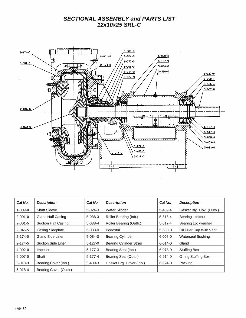
Cat No. Description Cat No. Description Cat No. Description
1-009-0 Shaft Sleeve 5-024-3 Water Slinger 5-409-4 Gasket Brg. Cov. (Outb.)
2-001-0 Gland Half Casing 5-038-3 Roller Bearing (Inb.) 5-516-4 Bearing Locknut
2-001-5 Suction Half Casing 5-038-4 Roller Bearing (Outb.) 5-517-4 Bearing Lockwasher
2-046-5 Casing Sideplate 5-083-0 Pedestal 5-530-0 Oil Filler Cap With Vent
2-174-0 Gland Side Liner 5-084-0 Bearing Cylinder 6-008-0 Waterseal Bushing
2-174-5 Suction Side Liner 5-127-0 Bearing Cylinder Strap 6-014-0 Gland
4-002-0 Impeller 5-177-3 Bearing Seal (Inb.) 6-073-0 Stuffing Box
5-007-0 Shaft 5-177-4 Bearing Seal (Outb.) 6-914-0 O-ring Stuffing Box
5-018-3 Bearing Cover (Inb.) 5-409-3 Gasket Brg. Cover (Inb.) 6-924-0 Packing
5-018-4 Bearing Cover (Outb.)
SECTIONAL ASSEMBLY and PARTS LIST12x10x25 SRL-C
Page 13
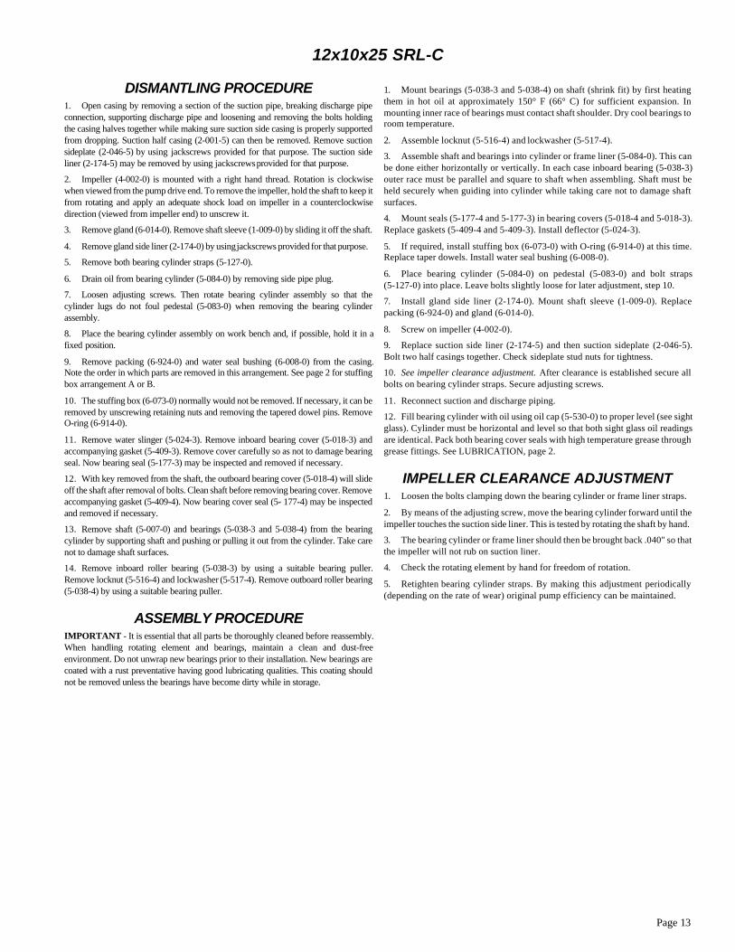
12x10x25 SRL-C
DISMANTLING PROCEDURE1. Open casing by removing a section of the suction pipe, breaking discharge pipeconnection, supporting discharge pipe and loosening and removing the bolts holdingthe casing halves together while making sure suction side casing is properly supportedfrom dropping. Suction half casing (2-001-5) can then be removed. Remove suctionsideplate (2-046-5) by using jackscrews provided for that purpose. The suction sideliner (2-174-5) may be removed by using jackscrews provided for that purpose.
2. Impeller (4-002-0) is mounted with a right hand thread. Rotation is clockwisewhen viewed from the pump drive end. To remove the impeller, hold the shaft to keep it from rotating and apply an adequate shock load on impeller in a counterclockwisedirection (viewed from impeller end) to unscrew it.
3. Remove gland (6-014-0). Remove shaft sleeve (1-009-0) by sliding it off the shaft.
4. Remove gland side liner (2-174-0) by using jackscrews provided for that purpose.
5. Remove both bearing cylinder straps (5-127-0).
6. Drain oil from bearing cylinder (5-084-0) by removing side pipe plug.
7. Loosen adjusting screws. Then rotate bearing cylinder assembly so that thecylinder lugs do not foul pedestal (5-083-0) when removing the bearing cylinderassembly.
8. Place the bearing cylinder assembly on work bench and, if possible, hold it in afixed position.
9. Remove packing (6-924-0) and water seal bushing (6-008-0) from the casing.Note the order in which parts are removed in this arrangement. See page 2 for stuffingbox arrangement A or B.
10. The stuffing box (6-073-0) normally would not be removed. If necessary, it can beremoved by unscrewing retaining nuts and removing the tapered dowel pins. RemoveO-ring (6-914-0).
11. Remove water slinger (5-024-3). Remove inboard bearing cover (5-018-3) andaccompanying gasket (5-409-3). Remove cover carefully so as not to damage bearingseal. Now bearing seal (5-177-3) may be inspected and removed if necessary.
12. With key removed from the shaft, the outboard bearing cover (5-018-4) will slideoff the shaft after removal of bolts. Clean shaft before removing bearing cover. Remove accompanying gasket (5-409-4). Now bearing cover seal (5- 177-4) may be inspectedand removed if necessary.
13. Remove shaft (5-007-0) and bearings (5-038-3 and 5-038-4) from the bearingcylinder by supporting shaft and pushing or pulling it out from the cylinder. Take carenot to damage shaft surfaces.
14. Remove inboard roller bearing (5-038-3) by using a suitable bearing puller.Remove locknut (5-516-4) and lockwasher (5-517-4). Remove outboard roller bearing(5-038-4) by using a suitable bearing puller.
ASSEMBLY PROCEDUREIMPORTANT - It is essential that all parts be thoroughly cleaned before reassembly.When handling rotating element and bearings, maintain a clean and dust-freeenvironment. Do not unwrap new bearings prior to their installation. New bearings arecoated with a rust preventative having good lubricating qualities. This coating shouldnot be removed unless the bearings have become dirty while in storage.
1. Mount bearings (5-038-3 and 5-038-4) on shaft (shrink fit) by first heatingthem in hot oil at approximately 150° F (66° C) for sufficient expansion. Inmounting inner race of bearings must contact shaft shoulder. Dry cool bearings toroom temperature.
2. Assemble locknut (5-516-4) and lockwasher (5-517-4).
3. Assemble shaft and bearings into cylinder or frame liner (5-084-0). This canbe done either horizontally or vertically. In each case inboard bearing (5-038-3)outer race must be parallel and square to shaft when assembling. Shaft must beheld securely when guiding into cylinder while taking care not to damage shaftsurfaces.
4. Mount seals (5-177-4 and 5-177-3) in bearing covers (5-018-4 and 5-018-3).Replace gaskets (5-409-4 and 5-409-3). Install deflector (5-024-3).
5. If required, install stuffing box (6-073-0) with O-ring (6-914-0) at this time.Replace taper dowels. Install water seal bushing (6-008-0).
6. Place bearing cylinder (5-084-0) on pedestal (5-083-0) and bolt straps(5-127-0) into place. Leave bolts slightly loose for later adjustment, step 10.
7. Install gland side liner (2-174-0). Mount shaft sleeve (1-009-0). Replacepacking (6-924-0) and gland (6-014-0).
8. Screw on impeller (4-002-0).
9. Replace suction side liner (2-174-5) and then suction sideplate (2-046-5).Bolt two half casings together. Check sideplate stud nuts for tightness.
10. See impeller clearance adjustment. After clearance is established secure allbolts on bearing cylinder straps. Secure adjusting screws.
11. Reconnect suction and discharge piping.
12. Fill bearing cylinder with oil using oil cap (5-530-0) to proper level (see sight glass). Cylinder must be horizontal and level so that both sight glass oil readingsare identical. Pack both bearing cover seals with high temperature grease throughgrease fittings. See LUBRICATION, page 2.
IMPELLER CLEARANCE ADJUSTMENT1. Loosen the bolts clamping down the bearing cylinder or frame liner straps.
2. By means of the adjusting screw, move the bearing cylinder forward until theimpeller touches the suction side liner. This is tested by rotating the shaft by hand.
3. The bearing cylinder or frame liner should then be brought back .040" so thatthe impeller will not rub on suction liner.
4. Check the rotating element by hand for freedom of rotation.
5. Retighten bearing cylinder straps. By making this adjustment periodically(depending on the rate of wear) original pump efficiency can be maintained.
Page 14
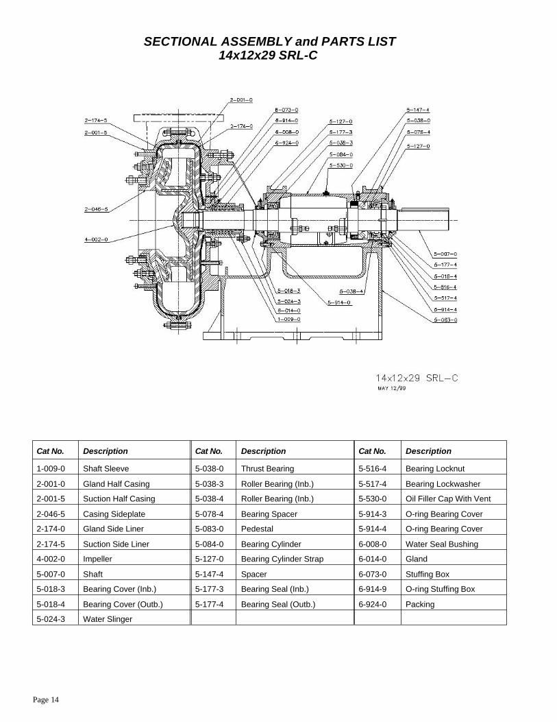
SECTIONAL ASSEMBLY and PARTS LIST14x12x29 SRL-C
Cat No. Description Cat No. Description Cat No. Description
1-009-0 Shaft Sleeve 5-038-0 Thrust Bearing 5-516-4 Bearing Locknut
2-001-0 Gland Half Casing 5-038-3 Roller Bearing (Inb.) 5-517-4 Bearing Lockwasher
2-001-5 Suction Half Casing 5-038-4 Roller Bearing (Inb.) 5-530-0 Oil Filler Cap With Vent
2-046-5 Casing Sideplate 5-078-4 Bearing Spacer 5-914-3 O-ring Bearing Cover
2-174-0 Gland Side Liner 5-083-0 Pedestal 5-914-4 O-ring Bearing Cover
2-174-5 Suction Side Liner 5-084-0 Bearing Cylinder 6-008-0 Water Seal Bushing
4-002-0 Impeller 5-127-0 Bearing Cylinder Strap 6-014-0 Gland
5-007-0 Shaft 5-147-4 Spacer 6-073-0 Stuffing Box
5-018-3 Bearing Cover (Inb.) 5-177-3 Bearing Seal (Inb.) 6-914-9 O-ring Stuffing Box
5-018-4 Bearing Cover (Outb.) 5-177-4 Bearing Seal (Outb.) 6-924-0 Packing
5-024-3 Water Slinger
Page 15
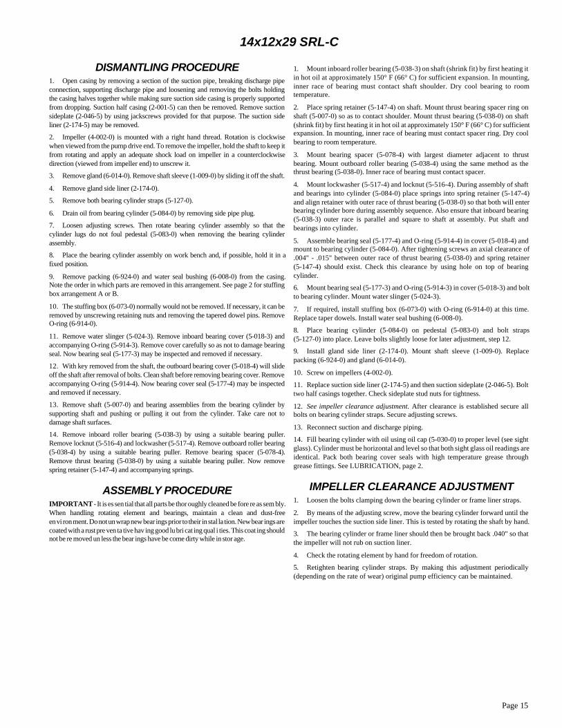
14x12x29 SRL-C
DISMANTLING PROCEDURE1. Open casing by removing a section of the suction pipe, breaking discharge pipeconnection, supporting discharge pipe and loosening and removing the bolts holdingthe casing halves together while making sure suction side casing is properly supportedfrom dropping. Suction half casing (2-001-5) can then be removed. Remove suctionsideplate (2-046-5) by using jackscrews provided for that purpose. The suction sideliner (2-174-5) may be removed.
2. Impeller (4-002-0) is mounted with a right hand thread. Rotation is clockwisewhen viewed from the pump drive end. To remove the impeller, hold the shaft to keep it from rotating and apply an adequate shock load on impeller in a counterclockwisedirection (viewed from impeller end) to unscrew it.
3. Remove gland (6-014-0). Remove shaft sleeve (1-009-0) by sliding it off the shaft.
4. Remove gland side liner (2-174-0).
5. Remove both bearing cylinder straps (5-127-0).
6. Drain oil from bearing cylinder (5-084-0) by removing side pipe plug.
7. Loosen adjusting screws. Then rotate bearing cylinder assembly so that thecylinder lugs do not foul pedestal (5-083-0) when removing the bearing cylinderassembly.
8. Place the bearing cylinder assembly on work bench and, if possible, hold it in afixed position.
9. Remove packing (6-924-0) and water seal bushing (6-008-0) from the casing.Note the order in which parts are removed in this arrangement. See page 2 for stuffingbox arrangement A or B.
10. The stuffing box (6-073-0) normally would not be removed. If necessary, it can beremoved by unscrewing retaining nuts and removing the tapered dowel pins. RemoveO-ring (6-914-0).
11. Remove water slinger (5-024-3). Remove inboard bearing cover (5-018-3) andaccompanying O-ring (5-914-3). Remove cover carefully so as not to damage bearingseal. Now bearing seal (5-177-3) may be inspected and removed if necessary.
12. With key removed from the shaft, the outboard bearing cover (5-018-4) will slideoff the shaft after removal of bolts. Clean shaft before removing bearing cover. Remove accompanying O-ring (5-914-4). Now bearing cover seal (5-177-4) may be inspectedand removed if necessary.
13. Remove shaft (5-007-0) and bearing assemblies from the bearing cylinder bysupporting shaft and pushing or pulling it out from the cylinder. Take care not todamage shaft surfaces.
14. Remove inboard roller bearing (5-038-3) by using a suitable bearing puller.Remove locknut (5-516-4) and lockwasher (5-517-4). Remove outboard roller bearing(5-038-4) by using a suitable bearing puller. Remove bearing spacer (5-078-4).Remove thrust bearing (5-038-0) by using a suitable bearing puller. Now removespring retainer (5-147-4) and accompanying springs.
ASSEMBLY PROCEDUREIMPORTANT - It is es sen tial that all parts be thor oughly cleaned be fore re as sem bly.When han dling ro tat ing el e ment and bear ings, main tain a clean and dust-freeen vi ron ment. Do not un wrap new bear ings prior to their in stal la tion. New bear ings arecoated with a rust pre ven ta tive hav ing good lu bri cat ing qual i ties. This coat ing shouldnot be re moved un less the bear ings have be come dirty while in stor age.
1. Mount inboard roller bearing (5-038-3) on shaft (shrink fit) by first heating itin hot oil at approximately 150° F (66° C) for sufficient expansion. In mounting,inner race of bearing must contact shaft shoulder. Dry cool bearing to roomtemperature.
2. Place spring retainer (5-147-4) on shaft. Mount thrust bearing spacer ring onshaft (5-007-0) so as to contact shoulder. Mount thrust bearing (5-038-0) on shaft(shrink fit) by first heating it in hot oil at approximately 150° F (66° C) for sufficient expansion. In mounting, inner race of bearing must contact spacer ring. Dry coolbearing to room temperature.
3. Mount bearing spacer (5-078-4) with largest diameter adjacent to thrustbearing. Mount outboard roller bearing (5-038-4) using the same method as thethrust bearing (5-038-0). Inner race of bearing must contact spacer.
4. Mount lockwasher (5-517-4) and locknut (5-516-4). During assembly of shaftand bearings into cylinder (5-084-0) place springs into spring retainer (5-147-4)and align retainer with outer race of thrust bearing (5-038-0) so that both will enterbearing cylinder bore during assembly sequence. Also ensure that inboard bearing(5-038-3) outer race is parallel and square to shaft at assembly. Put shaft andbearings into cylinder.
5. Assemble bearing seal (5-177-4) and O-ring (5-914-4) in cover (5-018-4) andmount to bearing cylinder (5-084-0). After tightening screws an axial clearance of.004" - .015" between outer race of thrust bearing (5-038-0) and spring retainer(5-147-4) should exist. Check this clearance by using hole on top of bearingcylinder.
6. Mount bearing seal (5-177-3) and O-ring (5-914-3) in cover (5-018-3) and bolt to bearing cylinder. Mount water slinger (5-024-3).
7. If required, install stuffing box (6-073-0) with O-ring (6-914-0) at this time.Replace taper dowels. Install water seal bushing (6-008-0).
8. Place bearing cylinder (5-084-0) on pedestal (5-083-0) and bolt straps(5-127-0) into place. Leave bolts slightly loose for later adjustment, step 12.
9. Install gland side liner (2-174-0). Mount shaft sleeve (1-009-0). Replacepacking (6-924-0) and gland (6-014-0).
10. Screw on impellers (4-002-0).
11. Replace suction side liner (2-174-5) and then suction sideplate (2-046-5). Bolttwo half casings together. Check sideplate stud nuts for tightness.
12. See impeller clearance adjustment. After clearance is established secure allbolts on bearing cylinder straps. Secure adjusting screws.
13. Reconnect suction and discharge piping.
14. Fill bearing cylinder with oil using oil cap (5-030-0) to proper level (see sightglass). Cylinder must be horizontal and level so that both sight glass oil readings are identical. Pack both bearing cover seals with high temperature grease throughgrease fittings. See LUBRICATION, page 2.
IMPELLER CLEARANCE ADJUSTMENT1. Loosen the bolts clamping down the bearing cylinder or frame liner straps.
2. By means of the adjusting screw, move the bearing cylinder forward until theimpeller touches the suction side liner. This is tested by rotating the shaft by hand.
3. The bearing cylinder or frame liner should then be brought back .040" so thatthe impeller will not rub on suction liner.
4. Check the rotating element by hand for freedom of rotation.
5. Retighten bearing cylinder straps. By making this adjustment periodically(depending on the rate of wear) original pump efficiency can be maintained.
Page 16
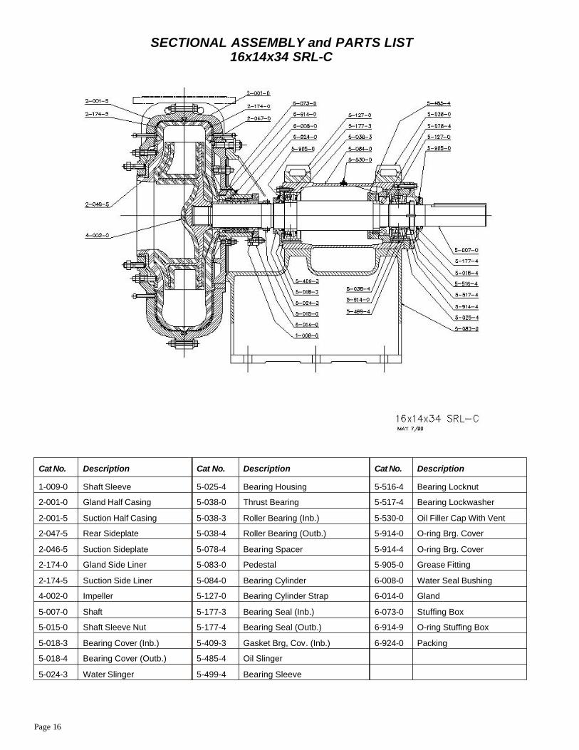
Cat No. Description Cat No. Description Cat No. Description
1-009-0 Shaft Sleeve 5-025-4 Bearing Housing 5-516-4 Bearing Locknut
2-001-0 Gland Half Casing 5-038-0 Thrust Bearing 5-517-4 Bearing Lockwasher
2-001-5 Suction Half Casing 5-038-3 Roller Bearing (Inb.) 5-530-0 Oil Filler Cap With Vent
2-047-5 Rear Sideplate 5-038-4 Roller Bearing (Outb.) 5-914-0 O-ring Brg. Cover
2-046-5 Suction Sideplate 5-078-4 Bearing Spacer 5-914-4 O-ring Brg. Cover
2-174-0 Gland Side Liner 5-083-0 Pedestal 5-905-0 Grease Fitting
2-174-5 Suction Side Liner 5-084-0 Bearing Cylinder 6-008-0 Water Seal Bushing
4-002-0 Impeller 5-127-0 Bearing Cylinder Strap 6-014-0 Gland
5-007-0 Shaft 5-177-3 Bearing Seal (Inb.) 6-073-0 Stuffing Box
5-015-0 Shaft Sleeve Nut 5-177-4 Bearing Seal (Outb.) 6-914-9 O-ring Stuffing Box
5-018-3 Bearing Cover (Inb.) 5-409-3 Gasket Brg, Cov. (Inb.) 6-924-0 Packing
5-018-4 Bearing Cover (Outb.) 5-485-4 Oil Slinger
5-024-3 Water Slinger 5-499-4 Bearing Sleeve
SECTIONAL ASSEMBLY and PARTS LIST16x14x34 SRL-C
Page 17
16x14x34 SRL-C
DISMANTLING PROCEDURE1. Open casing by removing a section of the suction pipe, breaking discharge pipeconnection, supporting discharge pipe and loosening and removing the bolts holdingthe casing halves together while making sure suction side casing is properly supportedfrom dropping. Suction half casing (2-001-5) can then be removed. Remove suctionsideplate (2-046-5) by using jackscrews provided for that purpose. The suction sideliner (2-174-5) may be removed.
2. Impeller (4-002-0) is mounted with a right hand thread. Rotation is clockwisewhen viewed from the pump drive end. To remove the impeller, hold the shaft to keep it from rotating and apply an adequate shock load on impeller in a counterclockwisedirection (viewed from impeller end) to unscrew it.
3. Remove gland (6-014-0). Remove shaft sleeve (1-009-0) by sliding it off the shaft.
4. Remove rear sideplate (2-047-0) by using jackscrews provided for that purpose.Remove gland side liner (2-174-0).
5. Remove both bearing cylinder straps (5-127-0).
6. Drain oil from bearing cylinder (5-084-0) by removing side pipe plug.
7. Loosen adjusting screws. Then rotate bearing cylinder assembly so that thecylinder lugs do not foul pedestal (5-083-0) when removing the bearing cylinderassembly.
8. Place the bearing cylinder assembly on work bench and, if possible, hold it in afixed position.
9. Remove packing (6-924-0) and water seal bushing (6-008-0) from the casing.Note the order in which parts are removed in this arrangement. See page 2 for stuffingbox arrangement A or B.
10. The stuffing box (6-073-0) normally would not be removed. If necessary, it can beremoved by unscrewing retaining nuts and removing the tapered dowel pins. RemoveO-ring (6-914-0).
11. Remove shaft sleeve nut (5-015-0). Remove water slinger (5-024-3). Removeinboard bearing cover (5-018-3) and accompanying gasket (5-409-3). Remove covercarefully so as not to damage bearing seal. Now bearing cover seal (5-177-3) may beinspected and removed if necessary.
12. With key removed from the shaft, the outboard bearing cover (5-018-4) will slideoff the shaft after removal of bolts. Clean shaft before removing bearing cover. Remove accompanying O-ring (5-914-4). Now bearing cover seal (5-177-4) may be inspectedand removed if necessary.
13. Remove shaft (5-007-0) and bearing assemblies from the bearing cylinder bysupporting shaft and using bearing housing (5-025-4) tap holes, jack the rotatingelement out of the bearing cylinder. Remove bearing housing O-ring (5-914-0).
14. Remove inboard roller bearing (5-038-3) by using a suitable bearing puller.Remove oil slinger (5-485-4). Now push or slide bearing housing (5-025-4) off towardthe impeller end of shaft. Remove springs in bearing housing. Remove bearing locknut(5-516-4) and lockwasher (5-517-4). Using SKF KM—31 withdrawal nut, removeoutboard roller bearing (5-038-4) and bearing spacer (5-078-4). Remove thrust bearing(5-038-0) by using a suitable bearing puller.
ASSEMBLY PROCEDUREIMPORTANT - It is essential that all parts be thoroughly cleaned before reassembly.When handling rotating element and bearings, maintain a clean and dust-freeenvironment. Do not unwrap new bearings prior to their installation. New bearings arecoated with a rust preventative having good lubricating qualities. This coating shouldnot be removed unless the bearings have become dirty while in storage.
1. Mount thrust bearing spacer ring on shaft (5-007-0) and contact shoulder. Mountthrust bearing (5-038-0) on shaft (shrink fit) by first heating it in hot oil atapproximately 150° F (66° C) for sufficient expansion. In mounting, inner race ofbearing must contact spacer ring. Dry cool bearing to room temperature.
2. Mount bearing spacer with largest diameter adjacent to thrust bearing. Withdrawal sleeve (5-078-4) together with outboard roller bearing (5-038-4) are placed on shaft.Inner race of bearing must contact spacer. Mount lockwasher (5-517-4) and locknut(5-516-4). Using locknut, drive withdrawal sleeve in outboard roller bearing so thatthrust bearing total clearance between rollers and outer race is set at .005-.007". Notewithdrawal sleeve movement of .015" reduces radial clearance of thrust bearing by.001" approximately. Lock in proper clearance position.
3. Place the four springs in bearing housing (5-025-4) and slide housing on shaft andover bearings. Assembly bearing seal (5-177-4) and O-ring (5-914-4) in cover(5-018-4) and mount to bearing housing using the three tapped holes in housing. Aftertightening screws an axial clearance of .005-.030" between outer race of thrust bearingand bearing housing should exist. Check this clearance by using the cored hole for oilreturn at bottom of housing. Mount oil slinger (5-485-4).
4. Mount inboard roller bearing (5-038-3) on shaft (shrink fit) by first heating it in hot oil at approximately 150° F (66° C) for sufficient expansion. In mounting, inner race ofbearing must contact shaft shoulder. Dry cool bearing to room temperature.
5. Mount O-ring (5-914-0) on housing. Assemble shaft and bearings into bearingcylinder (5-084-0). This can be done either horizontally or vertically. In each case,inboard bearing (5-038-3) outer race must be parallel and square to shaft whenassembling. Shaft must be held securely when guiding into cylinder while taking carenot to damage shaft surfaces.
6. Bolt bearing housing and cover assembly (5-025-4) and (5-018-4) to bearingcylinder (5-084-0). Mount bearing seal (5-177-3) in cover (5-018-3) and using gasket(5-409-3) bolt bearing cover to bearing cylinder. Mount water slinger (5-024-3). Installshaft sleeve nut (5-015-0).
7. If required, install stuffing box (6-073-0) with O-ring (6-914-0) at this time.Replace taper dowels. Install water seal bushing (6-008-0).
8. Place bearing cylinder (5-084-0) on pedestal (5-083-0) and bolt straps (5-127-0)into place. Leave bolts slightly loose for later adjustment, step 12.
9. Install gland side liner (2-174-0). and then rear sideplate (2-047-0). Mount shaftsleeve (1-009-0). Replace packing (6-924-0) and gland (6-014-0).
10. Screw on impeller (4-002-0). After seating on shaft shoulder, tighten shaft sleevenut (5-015-0).
11. Replace suction side liner (2-074-5) and then suction sideplate (2-046-5). Bolt twohalf casings together. Check sideplate stud nuts for tightness.
12. See impeller clearance adjustment. After clearance is established secure all boltson bearing cylinder straps. Secure adjusting screws.
13. Reconnect suction and discharge piping.
14. Fill bearing cylinder with oil using oil cap (5-530-0) to proper level (see sightglass). Cylinder must be horizontal and level so that both sight glass oil readings areidentical. Pack both bearing cover seals with high temperature grease through greasefittings (5-905-0). See LUBRICATION, page 2.
IMPELLER CLEARANCE ADJUSTMENT1. Loosen the bolts clamping down the bearing cylinder or frame liner straps.
2. By means of the adjusting screw, move the bearing cylinder forward until theimpeller touches the suction side liner. This is tested by rotating the shaft by hand.
3. The bearing cylinder or frame liner should then be brought back .040" so that theimpeller will not rub on suction liner.
4. Check the rotating element by hand for freedom of rotation.
5. Retighten bearing cylinder straps. By making this adjustment periodically(depending on the rate of wear) original pump efficiency can be maintained.
Page 18
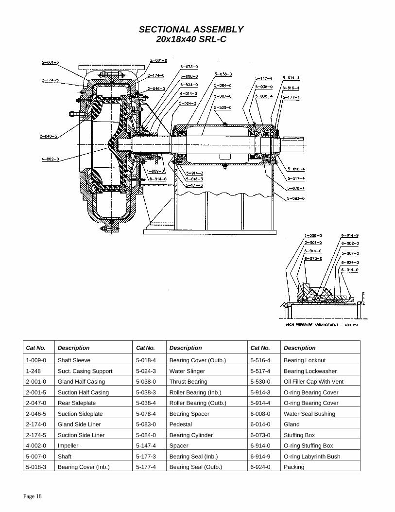
Cat No. Description Cat No. Description Cat No. Description
1-009-0 Shaft Sleeve 5-018-4 Bearing Cover (Outb.) 5-516-4 Bearing Locknut
1-248 Suct. Casing Support 5-024-3 Water Slinger 5-517-4 Bearing Lockwasher
2-001-0 Gland Half Casing 5-038-0 Thrust Bearing 5-530-0 Oil Filler Cap With Vent
2-001-5 Suction Half Casing 5-038-3 Roller Bearing (Inb.) 5-914-3 O-ring Bearing Cover
2-047-0 Rear Sideplate 5-038-4 Roller Bearing (Outb.) 5-914-4 O-ring Bearing Cover
2-046-5 Suction Sideplate 5-078-4 Bearing Spacer 6-008-0 Water Seal Bushing
2-174-0 Gland Side Liner 5-083-0 Pedestal 6-014-0 Gland
2-174-5 Suction Side Liner 5-084-0 Bearing Cylinder 6-073-0 Stuffing Box
4-002-0 Impeller 5-147-4 Spacer 6-914-0 O-ring Stuffing Box
5-007-0 Shaft 5-177-3 Bearing Seal (Inb.) 6-914-9 O-ring Labyrinth Bush
5-018-3 Bearing Cover (Inb.) 5-177-4 Bearing Seal (Outb.) 6-924-0 Packing
SECTIONAL ASSEMBLY20x18x40 SRL-C

Page 19
20x18x40 SRL-C
DISMANTLING PROCEDURE1. Open casing by removing a section of the suction pipe, breaking dischargepipe connection, supporting discharge pipe and loosening and removing the boltsholding the casing halves together while making sure suction side casing isproperly supported from dropping. Suction half casing (2-001-5) can then beremoved. Remove suction sideplate (2-046-5) by using jackscrews provided forthat purpose. The suction side liner (2-174-5) may be removed by usingjackscrews provided for that purpose.
2. Impeller (4-002-0) is mounted with a right hand thread. Rotation is clockwise when viewed from the pump drive end. To remove the impeller, hold the shaft tokeep it from rotating and apply an adequate shock load on impeller in acounterclockwise direction (viewed from impeller end) to unscrew it.
3. Remove gland (6-014-0). Remove Shaft sleeve (1-009-0) by sliding it off theshaft.
4. Remove rear sideplate (2-047-0) by using jackscrews provided for thatpurpose. Remove gland side liner (2-174-0) by using jackscrews provided for that purpose.
5. Remove bolts holding down bearing cylinder (5-084-0).
6. Drain oil from bearing cylinder (5-084-0) by removing the bottom pipe plug.
7. Loosen adjusting screws. Remove bearing cylinder assembly out fromcasing and off the pedestal (5-083-0).
8. Place the bearing cylinder assembly on work bench and, if possible, hold it ina fixed position.
9. Remove packing (6-924-0) and waterseal bushing (6-008-0) from the casing. Note the order in which parts are removed in this arrangement. See page 2 forstandard stuffing box arrangement or see sectional arrangement for heavy dutystuffing box..
10. The stuffing box (6-073-0) normally would not be removed. If necessary itcan be removed by unscrewing retaining nuts and removing the tapered dowelpins. Remove O-ring (6-914-0).
11. Remove water slinger (5-024-3). Remove inboard bearing cover (5-018-3)and accompanying O-ring (5-914-3). Remove cover carefully so as not to damage bearing seal (5-177-3). Now bearing seal may be inspected and removed ifnecessary.
12. With key removed from the shaft, the outboard bearing cover (5-018-4) willslide off the shaft after removal of bolts. Clean shaft before removing bearingcover. Remove accompanying O-ring (5-914-4). Now bearing cover seal(5-177-4) may be inspected and removed if necessary.
13. To remove shaft and bearings, hold bearing cylinder in a vertical positionusing cylinder body pads. Place shoulder type eyebolt in end of shaft (5-007-0)and pull out from cylinder.
14. Remove inboard roller bearing (5-038-3) by using a suitable bearing puller.Remove spring retainer (5-147-4) and springs. Remove bearing locknut (5-516-4) and lockwasher (5-517-4). Remove outboard roller bearing (5-038-4) by using asuitable bearing puller. Remove bearing spacer (5-078-4). Remove thrust bearing(5-038-0) by using a suitable bearing puller. Slide thrust bearing spacer ring offthe shaft.
ASSEMBLY PROCEDUREIMPORTANT - It is essential that all parts be thoroughly cleaned beforereassembly. When handling rotating element and bearings, maintain a clean anddust-free environment. Do not unwrap new bearings prior to their installation.New bearings are coated with a rust preventative having good lubricatingqualities. This coating should not be removed unless the bearings have becomedirty while in storage.
1. Mount inboard roller bearing (5-038-3) on shaft (shrink fit) by first heatingthem in hot oil at approximately 150° F (66° C) for sufficient expansion. Inmounting, inner race of bearing must contact shaft shoulder. Dry cool bearing toroom temperature.
2. Place spring retainer (5-147-4) on shaft and also outer race of thrust bearing.Mount thrust bearing spacer ring on shaft (5-007-0) to contact shoulder. Mountthrust bearing (5-038-0) on shaft (shrink fit) by first heating it in hot oil atapproximately 150° F (66° C) for sufficient expansion. In mounting, inner race ofbearing must contact spacer ring. Dry cool bearing to room temperature.
3. Mount bearing spacer (5-078-4) with largest diameter adjacent to thrustbearing (5-038-0). Mount outboard roller bearing (5-038-4) on shaft using thesame method as thrust bearing (5-038-0). Inner race of bearing must contactspacer. Mount lockwasher (5-517-4) and locknut (5-516-4) and tighten.
4. With bearing cylinder and shaft held securely in a vertical position begin tolower shaft in cylinder making sure that inboard bearing (5-038-3) outer race isparallel and square to shaft during assembly. At this time, place springs in springretainer (5-147-4) and fit into cylinder bore while making sure that the outer raceof thrust bearing (5-038-0) is adjacent to retainer. Put shaft and bearings intocylinder.
5. Assemble bearing seal (5-177-4) and O-ring (5-914-4) in cover (5-018-4)and mount to bearing cylinder (5-084-0). After tightening screws, an axialclearance of .004"-.015" between outer race of thrust bearing (5-038-0) andspring retainer (5-147-4) should exist. Check this clearance by using pipe tap hole on top of bearing cylinder.
6. Mount bearing seal (5-177-3) and O-ring (5-914-3) in cover (5-018-3) andbolt to bearing cylinder. Mount water slinger (5-024-3).
7. If required, install stuffing box (6-073-0) with O-ring (6-914-0) at this time.Replace taper dowels. Install water seal bushing (6-008-0).
8. Place assembled bearing cylinder on pedestal (5-083-0) and bolt into place.
9. Install gland side liner (2-174-0) and then rear sideplate (2-047-0). Mountshaft sleeve (1-009-0). Replace packing (6-924-0) and gland (6-014-0).
10. Screw on impeller (4-002-0).
11. Replace suction side liner (2-174-5) and then suction sideplate (2-046-5).Bolt two half casings together. Now check all sideplate stud nuts for tightness.
12. See impeller clearance adjustment. After clearance is established lockadjusting screws.
13. Fill bearing cylinder with oil using oil cap (5-530-0) to proper level (see sight glass). Cylinder must be horizontal and level so that both sight glass oil readingsare identical. Pack both bearing cover seals with high temperature grease throughgrease fittings. See LUBRICATION page 2.
14. Reconnect suction and discharge piping.
IMPELLER CLEARANCE ADJUSTMENT1. Loosen the bolts clamping down the bearing cylinder or frame liner straps.
2. By means of the adjusting screw, move the bearing cylinder forward until theimpeller touches the suction side liner. This is tested by rotating the shaft by hand.
3. The bearing cylinder or frame liner should then be brought back .040" so thatthe impeller will not rub on suction liner.
4. Check the rotating element by hand for freedom of rotation.
5. Retighten bearing cylinder straps. By making this adjustment periodically(depending on the rate of wear) original pump efficiency can be maintained.

Page 20
SECTIONAL ASSEMBLY and PARTS LIST6x6x21 SRL-XT
Cat No. Description Cat No. Description Cat No. Description
1-009-0 Shaft Sleeve 5-018-4 Bearing Cover (Outb.) 5-409-3 Brg. Cover Gasket (Inb.)
2-001-0 Gland Half Casing 5-024-3 Deflector 5-409-4 Brg. Cover Gasket (Outb.)
2-001-5 Suction Half Casing 5-038-3 Roller Bearing (Inb.) 5-516-4 Bearing Locknut
2-046-5 Casing Sideplate 5-038-4 Roller Bearing (Outb.) 5-517-4 Bearing Lockwasher
2-174-0 Gland Side Liner 5-083-0 Pedestal 5-530-0 Oil Filler Cap With Vent
2-174-5 Suction Side Liner 5-084-0 Bearing Cylinder 6-008-0 Waterseal Bushing
4-002-0 Impeller 5-127-0 Bearing Cylinder Strap 6-014-0 Gland
5-007-0 Shaft 5-177-3 Bearing Seal (Inb.) 6-924-0 Packing
5-018-3 Bearing Cover (Inb.) 5-177-4 Bearing Seal (Outb.)
Page 21
6x6x21 SRL-XT
DISMANTLING PROCEDURE1. Open casing by removing a section of the suction pipe, breaking dischargepipe connection, supporting discharge pipe and loosening and removing the boltsholding the casing halves together while making sure suction side casing isproperly supported from dropping. Suction half casing (2-001-5) can then beremoved. Remove casing sideplate (2-046-5). The suction side liner (rubber-lined 2-174-5) may be removed by using jackscrews provided for that purpose.
2. Impeller (4-002-0) is mounted with a right hand thread. Rotation is clockwise when viewed from the pump drive end. To remove the impeller, hold the shaft tokeep it from rotating and pound on a hardwood block held against the impellervane at the periphery in the counterclockwise direction when viewed from theimpeller end.
3. Remove gland side liner (rubber-lined 2-174-0) from the casing.
4. Remove gland (6-014-0). Remove shaft sleeve (1-009-0) by prying it loose at stuffing box and sliding it off the shaft.
5. Remove both bearing cylinder straps (5-127-9).
6. Drain oil from bearing cylinder (5-084-0) by removing the bottom pipe plug.
7. Remove adjusting screw mechanism which includes cotter pin, castle nut and washer. Then rotate bearing cylinder assembly so that the cylinder lug does notfoul pedestal (5-083-0) when removing the bearing cylinder assembly.
8. Place the bearing cylinder assembly on work bench and, if possible, hold thecylinder in a fixed position.
9. Remove packing (6-924-0) and bushing (6-008-0) from the casing. Note theorder in which parts are removed in this arrangement. See page 2 for stuffing boxarrangement A or B.
10. Remove deflector (5-024-3) from the shaft. Remove inboard bearing cover(5-018-3) and accompanying gasket (5-409-3). Now bearing seal (5-177-3) maybe inspected and removed if necessary.
11. With sheave and key removed from the shaft, the outboard bearing cover(5-018-4) will slide off the shaft after removal of bolts. Clean shaft beforeremoving bearing cover. Remove accompanying gasket (5-409-4). Now bearingseal (5-177-4) may be inspected and removed if necessary.
12. Remove shaft (5-007-0) and bearings (5-038-3 and 5-038-4) from thebearing cylinder using a drift pin and hammer or a hydraulic press if available.
13. Remove bearing locknut (5-516-4) and lockwasher (5-517-4). Removebearings by using a hydraulic press or suitable bearing puller.
ASSEMBLY PROCEDUREIMPORTANT - It is essential that all parts be thoroughly cleaned beforereassembly. When handling rotating elements and bearings, maintain a clean anddust-free environment. Do not unwrap new bearings prior to their installation.New bearings are coated with a rust preventative having good lubricatingqualities. This coating should not be removed unless the bearings have becomedirty while in storage.
1. Mount bearings (5-038-3 an 5-038-4) on shaft (shrink fit) by first heatingthem in hot oil at approximately 150° F (66° C) for sufficient expansion. Inmounting, inner race of bearings must contact shaft shoulder. Dry cool bearings to room temperature.
2. Assemble lockwasher (5-517-0) and locknut (5-516-4).
3. Assemble shaft and bearings into cylinder or frame liner (5-084-0). This canbe done either horizontally or vertically. In each case inboard bearing (5-038-3)outer race must be parallel and square to shaft when assembling. Shaft must beheld securely when guiding into cylinder while taking care not to damage shaftsurfaces.
4. Mount seals (5-177-4 and 5-177-3) in bearing covers (5-018-4 and 5-018-3).Replace gaskets (5-409-4 and 5-409-3). Install deflector (5-040-3).
5. Install waterseal bushing (6-008-0).
6. Place bearing cylinder or frame liner on pedestal (5-083-0) and bolt bearingcylinder straps (5-127-9) into place. Leave bolts slightly loose for lateradjustment, step 11.
Reassemble adjusting screw mechanism.
7. Mount shaft sleeve (1-009-0). Replace packing (6-924-0) and gland(6-014-0). Check if waterseal bushing (6-008-0) is concentric with sleeve.
8. Replace gland side liner (2-174-0). Do not use excessive force on liner studnuts.
9. Screw on impeller (4-002-0).
10. Replace suction side liner (2-714-5). Replace casing (2-046-5). Do not useexcessive force on casing sideplate stud nuts. Bolt two half casings together.Check casing sideplate stud nuts for tightness.
11. See impeller clearance adjustment. After clearance is established, secure allbolts on bearing cylinder straps.
12. Reconnect suction and discharge piping.
13. Fill cylinder or frame liner with oil to proper level and pack both bearingcover seals with high temperature grease through connections provided. SeeLUBRICATION page 2.
IMPELLER CLEARANCE ADJUSTMENT1. Loosen the bolts clamping down the bearing cylinder or frame liner straps.
2. By means of the adjusting screw, move the bearing cylinder forward until theimpeller touches the suction sideplate. This is tested by rotating the shaft by hand.
3. The bearing cylinder or frame liner should then be brought back 1/16" so thatthe impeller will not rub on casing sideplate.
4. Check the rotating element by hand for freedom of rotation.
5. Retighten bearing cylinder straps. By making this adjustment periodically(depending on the rate of wear) original pump efficiency can be maintained.
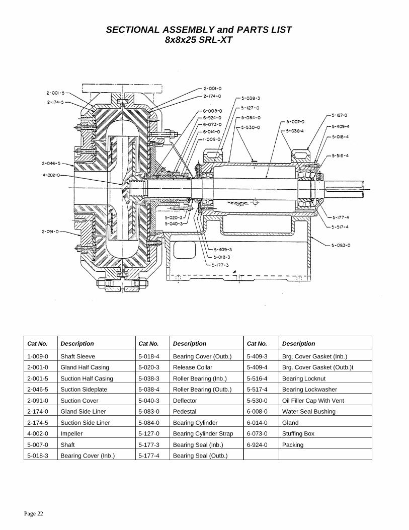
Page 22
SECTIONAL ASSEMBLY and PARTS LIST8x8x25 SRL-XT
Cat No. Description Cat No. Description Cat No. Description
1-009-0 Shaft Sleeve 5-018-4 Bearing Cover (Outb.) 5-409-3 Brg. Cover Gasket (Inb.)
2-001-0 Gland Half Casing 5-020-3 Release Collar 5-409-4 Brg. Cover Gasket (Outb.)t
2-001-5 Suction Half Casing 5-038-3 Roller Bearing (Inb.) 5-516-4 Bearing Locknut
2-046-5 Suction Sideplate 5-038-4 Roller Bearing (Outb.) 5-517-4 Bearing Lockwasher
2-091-0 Suction Cover 5-040-3 Deflector 5-530-0 Oil Filler Cap With Vent
2-174-0 Gland Side Liner 5-083-0 Pedestal 6-008-0 Water Seal Bushing
2-174-5 Suction Side Liner 5-084-0 Bearing Cylinder 6-014-0 Gland
4-002-0 Impeller 5-127-0 Bearing Cylinder Strap 6-073-0 Stuffing Box
5-007-0 Shaft 5-177-3 Bearing Seal (Inb.) 6-924-0 Packing
5-018-3 Bearing Cover (Inb.) 5-177-4 Bearing Seal (Outb.)
Page 23
8x8x25 SRL-XT
DISMANTLING PROCEDURE1. Remove section of suction pipe adjacent to suction casing (2-001-5). Casingis provided with removable cover (2-091-0) with suction (2-046-5) attached.Cover is held to casing by (12) studs and retaining nuts of which (4) hold suctionside liner (2-174-5) in place. Remove cover and attached suction sideplate bymeans of jackscrews provided. If necessary, remove suction sideplate from coverattached by (4) retaining studs and nuts. Break discharge connection, supportdischarge pipe, loosen and remove bolts holding casing halves. Make sure suction casing is supported from dropping. After suction casing is removed, suction sideliner (2-174-5) can be removed with jackscrews provided.
2. Impeller (4-002-0) is mounted with a right hand thread. Rotation is clockwise viewed from the pump drive end. To remove the impeller, first remove the shaftsleeve nut (5- 020-3). This is done by removing the two (2) Socket Head . Thenusing one as jackscrew in tapped hole at crown of nut, force joints apartsufficiently to lever one nut half clear from shaft shoulder. Other half may then beremoved by hitting nut with wooden mallet or of similar soft material to preventdamage to nut half. With nut off, impeller can be easily removed from shaft by the application of shock load counterclockwise (viewed from impeller end) whileholding shaft from rotating.
3. Remove gland (6-014-0). Remove shaft sleeve (1-009-0) by sliding if off theshaft.
4. Remove gland side liner (2-174-0) by means of jackscrews provided.
5. Remove both bearing cylinder straps (5-127-0).
6. Drain oil from bearing cylinder (5-084-0) by removing side pipe plug.
7. Loosen adjusting screws. Then rotate bearing cylinder assembly so that thecylinder lugs do not foul pedestal (5-083-0) when removing the bearing cylinderassembly.
8. Place the bearing cylinder assembly on work bench and, if possible, hold it ina fixed position.
9. Remove packing (6-924-0) and waterseal bushing (6-008-0) from thestuffing box. Note the order in which parts are removed in this arrangement. Seepage 2 for stuffing box arrangement A or B.
10. Stuffing box (6-073-0) normally would not be removed unless watersealbushing (6- 008-0) needs replacement. If required, unscrew (4) retaining socketcapscrews. Then using two (2) jackscrews in tapped holes remove stuffing boxfrom casing.
11. Remove deflector (5-040-3). Remove inboard bearing cover (5-018-3) andaccompanying gasket (5-409-3). Remove cover carefully so as not to damagebearing seal. Now bearing seal (5-177-3) may be inspected and removed, ifnecessary.
12. With key removed from shaft, the outboard bearing cover (5-018-4) willslide off the shaft after removal of bolts. Clean shaft before removing bearingcover. Remove accompanying gasket (5-409-4). Now bearing cover seal(5-177-4) may be inspected and removed, if necessary.
13. Remove shaft (5-007-0) and bearings (5-038-3) and (5-038-4) from thebearing cylinder by supporting shaft and pushing or pulling it out from thecylinder. Take care not to damage shaft surfaces.
14. Remove inboard roller bearing (5-038-3) by using a suitable bearing puller.Remove locknut (5-516-4) and lockwasher (5-517-4). Remove outboard rollerbearing (5-038-4) by using a suitable bearing puller.
ASSEMBLY PROCEDUREIMPORTANT- It is essential that all parts be thoroughly cleaned beforereassembly. When handling rotating elements and bearings, maintain a clean anddust-free environment. Do not unwrap new bearings prior to their installation.New bearings are coated with a rust preventative having good lubricatingqualities. This coating should not be removed unless the bearings have becomedirty while in storage.
1. Mount bearings (5-038-3 an 5-038-4) on shaft (shrink fit) by first heatingthem in hot oil at approximately 150° F (66° C) for sufficient expansion. Inmounting, inner race of bearings must contact shaft shoulder. Dry cool bearings to room temperature.
2. Assemble lockwasher (5-517-4) and locknut (5-516-4).
3. Assemble shaft and bearings into cylinder or frame liner (5-084-0). This canbe done either horizontally or vertically. In each case inboard bearing (5-038-3)outer race must be parallel and square to shaft when assembling. Shaft must beheld securely when guiding into cylinder while taking care not to damage shaftsurfaces.
4. Mount seals (5-177-4 and 5-177-3) in bearing covers (5-018-4 and 5-018-3).Replace gaskets (5-409-4 and 5-409-3). Bolt covers to bearing cylinder(5-084-0). Install deflector (5-040-3).
5. If removed from casing, re-install stuffing box (6-073-0) at this time. Installwater seal bushing (6-008-0) and mount stuffing box in gland half casing(2-001-0), using two straight dowels to locate the stuffing box.
6. Place bearing cylinder (5-084-0) on pedestal (5-083-0) and bolt straps(5-127-0) into place. Leave bolts slightly loose for later adjustment, step 10.
7. Install gland side liner (2-174-0). Re-assemble sleeve nut (5-020-3) andmount against shaft shoulder. Mount sleeve (1-009-0). Replace packing(6-924-0) and gland (6-014-0).
8. Screw on impeller (4-002-0).
9. Replace suction side liner (2-714-5) and replace retaining studs finger tight.Replace suction cover (2-091-0) complete with suction sideplate (2-046-5).Secure cover to casing and tighten side liner and sideplate retaining stud nuts.Bolt casing halves together and then recheck above-mentioned nuts for tightness.
10. See impeller clearance adjustment. After clearance is established secure allbolts on bearing cylinder straps. Secure adjusting screws.
11. Reconnect suction and discharge piping. 12. Fill bearing cylinder with oilusing oil cap (5-030-0) to proper level (see sight glass). Cylinder must behorizontal and level so that both sight glass oil readings are identical. Pack bothbearing cover seals with high temperature grease through grease fittings oncovers. See LUBRICATION page 2.
IMPELLER CLEARANCE ADJUSTMENT 1. Loosen the bolts clamping down the bearing cylinder or frame liner straps.
2. By means of the adjusting screw, move the bearing cylinder forward until theimpeller touches the suction sideplate. This is tested by rotating the shaft by hand.
3. The bearing cylinder or frame liner should then be brought back 1/16" so thatthe impeller will not rub on suction sideplate.
4. Check the rotating element by hand for freedom of rotation.
5. Retighten bearing cylinder straps. By making this adjustment periodically(depending on the rate of wear) original pump efficiency can be maintained.
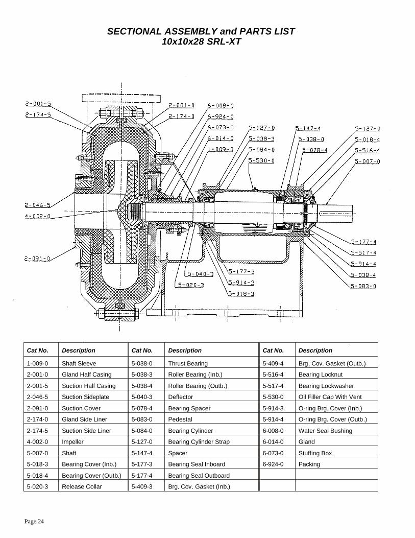
Page 24
SECTIONAL ASSEMBLY and PARTS LIST10x10x28 SRL-XT
Cat No. Description Cat No. Description Cat No. Description
1-009-0 Shaft Sleeve 5-038-0 Thrust Bearing 5-409-4 Brg. Cov. Gasket (Outb.)
2-001-0 Gland Half Casing 5-038-3 Roller Bearing (Inb.) 5-516-4 Bearing Locknut
2-001-5 Suction Half Casing 5-038-4 Roller Bearing (Outb.) 5-517-4 Bearing Lockwasher
2-046-5 Suction Sideplate 5-040-3 Deflector 5-530-0 Oil Filler Cap With Vent
2-091-0 Suction Cover 5-078-4 Bearing Spacer 5-914-3 O-ring Brg. Cover (Inb.)
2-174-0 Gland Side Liner 5-083-0 Pedestal 5-914-4 O-ring Brg. Cover (Outb.)
2-174-5 Suction Side Liner 5-084-0 Bearing Cylinder 6-008-0 Water Seal Bushing
4-002-0 Impeller 5-127-0 Bearing Cylinder Strap 6-014-0 Gland
5-007-0 Shaft 5-147-4 Spacer 6-073-0 Stuffing Box
5-018-3 Bearing Cover (Inb.) 5-177-3 Bearing Seal Inboard 6-924-0 Packing
5-018-4 Bearing Cover (Outb.) 5-177-4 Bearing Seal Outboard
5-020-3 Release Collar 5-409-3 Brg. Cov. Gasket (Inb.)
Page 25
10x10x28 SRL-XT
DISMANTLING PROCEDURE1. Remove section of suction pipe adjacent to suction casing (2-001-5). Casingis provided with removable cover (2-091-0) with suction sideplate (2-046-5)attached. Cover is held to casing by (12) studs and retaining nuts of which (4) hold suction side liner (2-174-5) in place. Remove cover and attached suction sideplate by means of jackscrews provided. If necessary, remove suction sideplate fromcover attached by (4) retaining studs and nuts.
Break discharge connection, support discharge pipe, loosen and remove boltsholding casing halves. Make sure suction casing is supported from dropping.After suction casing is removed, suction side liner (2-174-5) can be removed withjackscrews provided.
2. Impeller (4-002-0) is mounted with a right hand thread. Rotation is clockwise viewed from the pump drive end. To remove the impeller, first remove the shaftsleeve nut (5- 020-3). This is done by removing the two (2) Socket Head . Thenusing one as jackscrew in tapped hole at crown of nut, force joints apartsufficiently to lever one nut half clear from shaft shoulder. Other half may then beremoved by hitting nut with wooden mallet or of similar soft material to preventdamage to nut half. With nut off, impeller can be easily removed from shaft by the application of shock load counterclockwise (viewed from impeller end) whileholding shaft from rotating.
3. Remove gland (6-014-0). Remove shaft sleeve (1-009-0) by sliding if off theshaft.
4. Remove gland side liner (2-174-0) by means of jackscrews provided.
5. Remove both bearing cylinder straps (5-127-0).
6. Drain oil from bearing cylinder (5-084-0) by removing side pipe plug.
7. Loosen adjusting screws. Then rotate bearing cylinder assembly so that thecylinder lugs do not foul pedestal (5-083-0) when removing the bearing cylinderassembly.
8. Place the bearing cylinder assembly on work bench and, if possible, hold it ina fixed position.
9. Remove packing (6-924-0) and water seal bushing (6-008-0) from thestuffing box. Note the order in which parts are removed in this arrangement. Seepage 2 for stuffing box arrangement A or B.
10. Stuffing box (6-073-0) normally would not be removed unless bushing(6-008-0) needs replacement. If required, unscrew (4) retaining socket capscrews. Then using two (2) jackscrews in tapped holes remove stuffing box from casing.
11. Remove deflector (5-040-3). Remove inboard bearing cover (5-018-3) andaccompanying O-ring (5-914-3). Remove cover carefully so as not to damagebearing seal. Now bearing seal (5-177-3) may be inspected and removed, ifnecessary.
12. With key removed from shaft, the outboard bearing cover (5-018-4) willslide off the shaft after removal of bolts. Clean shaft before removing bearingcover. Remove accompanying O-ring (5-194-4). Now bearing cover seal(5-177-4) may be inspected and removed, if necessary.
13. Remove shaft (5-007-0) and bearing assemblies from the bearing cylinder bysupporting shaft and pushing or pulling it out from the cylinder. Take care not todamage shaft surfaces.
14. Remove inboard roller bearing (5-038-3) by using a suitable bearing puller.Remove locknut (5-516-4) and lockwasher (5-517-4). Remove outboard rollerbearing (5-038-4) by using a suitable bearing puller. Remove bearing spacer(5-078-4). Remove thrust bearing (5-038-0) by using a suitable bearing puller.Now remove spring retainer (5- 147-4) and accompanying springs.
ASSEMBLY PROCEDUREIMPORTANT - It is essential that all parts be thoroughly cleaned beforereassembly. When handling rotating elements and bearings, maintain a clean anddust-free environment. Do not unwrap new bearings prior to their installation.New bearings are coated with a rust preventative having good lubricatingqualities. This coating should not be removed unless the bearings have becomedirty while in storage.
1. Mount inboard roller bearing (5-038-3) on shaft (shrink fit) by first heating itin hot oil at approximately 150° F (66° C) for sufficient expansion. In mounting,inner race of bearing must contact shaft shoulder. Dry cool bearing to roomtemperature.
2. Place spring retainer (5-147-4) on shaft and also outer race of thrust bearing.Mount thrust bearing spacer ring on shaft (5-007-0) to contact shoulder. Mountthrust bearing (5-038-0) on shaft (shrink fit) by first heating it in hot oil atapproximately 150° F (66° C) for sufficient expansion. In mounting, inner race ofbearing must contact spacer ring. Dry cool bearing to room temperature.
3. Mount bearing spacer (5-078-4) with largest diameter adjacent to thrustbearing (5-038-0). Mount outboard roller bearing (5-038-4) on shaft using thesame method as thrust bearing (5-038-0). Inner race of bearing must contactspacer.
4. Mount (5-517-4) and locknut (5-516-4). During assembly of shaft andbearings into cylinder (5-084-0) place springs into spring retainer (5-147-4) andalign retainer with outer race of thrust bearing (5-038-0) so that both will enterbearing cylinder bore during assembly sequence. Also ensure that inboardbearing (5-038-3) outer race is parallel and square to shaft at assembly. Put shaftand bearings into cylinder..
5. Assemble bearing seal (5-177-4) and O-ring (5-914-4) in cover (5-018-4)and mount to bearing cylinder (5-084-0). After tightening screws, an axialclearance of .004" - .015" between outer race of thrust bearing (5-038-0) andspring retainer (5-147-4) should exist. Check this clearance by using hole on topof bearing cylinder.
6. Mount bearing seal (5-177-3) and O-ring (5-914-3) in cover (5-018-3) andbolt to bearing cylinder. Mount deflector (5-040-3).
7. If removed from casing, re-install stuffing box (6-073-0) at this time. Installwater seal bushing (6-008-0) and mount stuffing box in gland half casing(2-001-0), using two straight dowels to locate the stuffing box.
8. Place bearing cylinder (5-084-0) on pedestal (5-083-0) and bolt straps(5-127-0) into place. Leave bolts slightly loose for later adjustment, step 12.
9. Install gland side liner (2-174-0). Re-assemble sleeve nut (5-020-3) andmount against shaft shoulder. Mount sleeve (1-009-0). Replace packing(6-924-0) and gland (6-014-0).
10. Screw on impeller (4-002-0).
11. Replace suction side liner (2-714-5) and replace retaining studs finger tight.Replace suction cover (2-091-0) complete with suction sideplate (2-046-5).Secure cover to casing and tighten side liner and sideplate retaining stud nuts.Bolt casing halves together and then recheck above-mentioned nuts for tightness.
12. See impeller clearance adjustment. After clearance is established secure allbolts on bearing cylinder straps. Secure adjusting screws.
13. Reconnect suction and discharge piping.
14. Fill bearing cylinder with oil using oil cap (5-530-0) to proper level (see sight glass). Cylinder must be horizontal and level so that both sight glass oil readingsare identical. Pack both bearing cover seals with high temperature grease throughgrease fittings on covers. See LUBRICATION page 2.
IMPELLER CLEARANCE ADJUSTMENT1. Loosen the bolts clamping down the bearing cylinder or frame liner straps.
2. By means of the adjusting screw, move the bearing cylinder forward until theimpeller touches the suction sideplate. This is tested by rotating the shaft by hand.
3. The bearing cylinder or frame liner should then be brought back 1/16" so thatthe impeller will not rub on suction sideplate.
4. Check the rotating element by hand for freedom of rotation.
5. Retighten bearing cylinder straps. By making this adjustment periodically(depending on the rate of wear) original pump efficiency can be maintained.
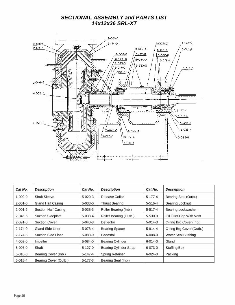
Page 26
SECTIONAL ASSEMBLY and PARTS LIST14x12x36 SRL-XT
Cat No. Description Cat No. Description Cat No. Description
1-009-0 Shaft Sleeve 5-020-3 Release Collar 5-177-4 Bearing Seal (Outb.)
2-001-0 Gland Half Casing 5-038-0 Thrust Bearing 5-516-4 Bearing Locknut
2-001-5 Suction Half Casing 5-038-3 Roller Bearing (Inb.) 5-517-4 Bearing Lockwasher
2-046-5 Suction Sideplate 5-038-4 Roller Bearing (Outb.) 5-530-0 Oil Filler Cap With Vent
2-091-0 Suction Cover 5-040-3 Deflector 5-914-3 O-ring Brg Cover (Inb.)
2-174-0 Gland Side Liner 5-078-4 Bearing Spacer 5-914-4 O-ring Brg Cover (Outb.)
2-174-5 Suction Side Liner 5-083-0 Pedestal 6-008-0 Water Seal Bushing
4-002-0 Impeller 5-084-0 Bearing Cylinder 6-014-0 Gland
5-007-0 Shaft 5-127-0 Bearing Cylinder Strap 6-073-0 Stuffing Box
5-018-3 Bearing Cover (Inb.) 5-147-4 Spring Retainer 6-924-0 Packing
5-018-4 Bearing Cover (Outb.) 5-177-3 Bearing Seal (Inb.)
Page 27
14x12x36 SRL-XT
DISMANTLING PROCEDURE1. Remove section of suction pipe adjacent to suction casing (2-001-5). Casingis provided with removable cover (2-091-0) with suction sideplate (2-046-5)attached. Cover is held to casing by (12) studs and retaining nuts of which (4) hold suction sideliner (2-174-5) in place. Remove cover and attached suction sidelockwasher (5-517-4) plate by means of jackscrews provided. If necessary,remove suction sideplate from cover attached by (4) retaining studs and nuts.
Break discharge connection, support discharge pipe, loosen and remove boltsholding casing halves. Make sure suction casing is supported from dropping.After suction casing is removed, suction side liner (2-174-5) can be removed withjackscrews provided.
2. Impeller (4-002-0) is mounted with a right hand thread. Rotation is clockwise viewed from the pump drive end. To remove the impeller, first remove the shaftsleeve nut (5-020-3). This is done by removing the two (2) Socket HeadCapscrews. Then using one as jackscrew in tapped hole at crown of nut, forcejoints apart sufficiently to lever one nut half clear from shaft shoulder. Other halfmay then be removed by hitting nut with wooden mallet or of similar soft material to prevent damage to nut half. With cut off, impeller can be easily removed fromshaft by the application of shock load counterclockwise (viewed from impellerend) while holding shaft from rotating.
3. Remove gland (6-014-0). Remove shaft sleeve (1-009-0) by sliding if off theshaft.
4. Remove gland side liner (2-174-0) by means of jackscrews provided.
5. Remove both bearing cylinder straps (5-127-0).
6. Drain oil from bearing cylinder (5-084-0) by removing side pipe plug.
7. Loosen adjusting screws. Then rotate bearing cylinder assembly so that thecylinder lugs do not foul pedestal (5-083-0) when removing the bearing cylinderassembly.
8. Place the bearing cylinder assembly on work bench and, if possible, hold it ina fixed position.
9. Remove packing (6-924-0) and water seal bushing (6-008-0) from thestuffing box. Note the order in which parts are removed in this arrangement. Seepage 2 for stuffing box arrangement A or B.
10. Stuffing box (6-073-0) normally would not be removed unless stuffing boxbushing (6-008-0) needs replacement. If required, unscrew (4) retaining socketcapscrews. Then using two (2) jackscrews in tapped holes remove stuffing boxfrom casing.
11. Remove deflector (5-040-3). Remove inboard bearing cover (5-018-3) andaccompanying O-ring (5-914-3). Remove cover carefully so as not to damagebearing seal. Now bearing seal (5-177-3) may be inspected and removed, ifnecessary.
12. With key removed from shaft, the outboard bearing cover (5-018-4) willslide off the shaft after removal of bolts. Clean shaft before removing bearingcover. Remove accompanying O-ring (5-194-4). Now bearing cover seal(5-177-4) may be inspected and removed if necessary.
13. Remove shaft (5-007-0) and bearing assemblies from the bearing cylinder bysupporting shaft and pushing or pulling it out from the cylinder. Take care not todamage shaft surfaces.
14. Remove inboard roller bearing (5-038-3) by using a suitable bearing puller.Remove locknut (5-516-4) and lockwasher (5-517-4). Remove outboard rollerbearing (5-038-4) by using a suitable bearing puller. Remove bearing spacer(5-078-4). Remove thrust bearing (5-038-0) by using a suitable bearing puller.Now remove spring retainer(5-147-4) and accompanying springs.
ASSEMBLY PROCEDUREIMPORTANT - It is essential that all parts be thoroughly cleaned beforereassembly. When handling rotating elements and bearings, maintain a clean anddust-free environment. Do not unwrap new bearings prior to their installation.New bearings are coated with a rust preventative having good lubricatingqualities. This coating should not be removed unless the bearings have becomedirty while in storage.
1. Mount inboard roller bearing (5-038-3) on shaft (shrink fit) by first heating itin hot oil at approximately 150° F (66° C) for sufficient expansion. In mounting,inner race offering must contact shaft shoulder. Dry cool bearing to roomtemperature.
2. Place spring retainer (5-147-4) on shaft and also outer race of thrust bearing.Mount thrust bearing spacer ring on shaft (5-007-0) to contact shoulder. Mountthrust bearing(5-038-0) on shaft (shrink fit) by first heating it in hot oil atapproximately 150° F (66° C)for sufficient expansion. In mounting, inner race ofbearing must contact spacer ring. Dry cool bearing to room temperature.
3. Mount bearing spacer (5-078-4) with largest diameter adjacent to thrustbearing (5-038-0). Mount outboard roller bearing (5-038-4) on shaft using thesame method as thrust bearing (5-038-0). Inner race of bearing must contactspacer. Mount (5-517-4) and locknut (5-516-4) and tighten.
4. With bearing cylinder and shaft held securely in a vertical position begin tolower shaft in cylinder making sure that inboard bearing (5-308-3) outer race isparallel and square to shaft during assembly. At this time, place springs in springretainer (5-147-4)and fit into cylinder bore while making sure that the outer raceof thrust bearing(5-038-0) is adjacent to retainer. Put shaft and bearings intocylinder.
5. Assemble bearing seal (5-177-4) and O-rings (5-914-4) in cover (5-018-4)and mount to bearing cylinder (5-084-0). After tightening screws, an axialclearance of .004"- .015" between outer race of thrust bearing (5-038-0) andspring retainer (5-147-4)should exist. Check this clearance by using pipe tap holeon top of bearing cylinder.
6. Mount bearing seal (5-177-3) and O-rings (5-914-3) in cover (5-018-3) andbolt to bearing cylinder. Mount deflector (5-040-3).
7. If removed from casing, re-install stuffing box (6-073-0) at this time. Installwater seal bushing (6-008-0) and mount stuffing box in gland half casing(2-001-0), using two straight dowels to locate the stuffing box.
8. Place bearing cylinder (5-084-0) on pedestal (5-083-0) and bolt straps(5-127-0) into place. Leave bolts slightly loose for later adjustment. Step 12.
9. Install gland side liner (2-174-0). Re-assemble sleeve nut (5-020-3) andmount against shaft shoulder. Mount sleeve (1-009-0). Replace packing(6-924-0) and gland (6-014-0).
10. Screw on impeller (4-002-0).
11. Replace suction side liner (2-714-5) and replace retaining studs finger tight.Replace suction cover (2-091-0) complete with suction sideplate (2-046-5).Secure cover to casing and tighten side liner and sideplate retaining stud nuts.Bolt casing halves together and then recheck above-mentioned nuts for tightness.
12. See impeller clearance adjustment. After clearance is established secure allbolts on bearing cylinder straps. Secure adjusting screws.
13. Reconnect suction and discharge piping.
14. Fill bearing cylinder with oil using oil cap (5-530-0) to proper level (see sight glass). Cylinder must be horizontal and level so that both sight glass oil readingsare identical. Pack both bearing cover seals with high temperature grease throughgrease fittings on covers. See LUBRICATION page 2.
IMPELLER CLEARANCE ADJUSTMENT1. Loosen the bolts clamping down the bearing cylinder or frame liner straps.
2. By means of the adjusting screw, move the bearing cylinder forward until theimpeller touches the suction . This is tested by rotating the shaft by hand.
3. The bearing cylinder or frame liner should then be brought back 1/16" so thatthe impeller will not rub on suction sideplate.
4. Check the rotating element by hand for freedom of rotation.
5. Retighten bearing cylinder straps. By making this adjustment periodically(depending on the rate of wear) original pump efficiency can be maintained
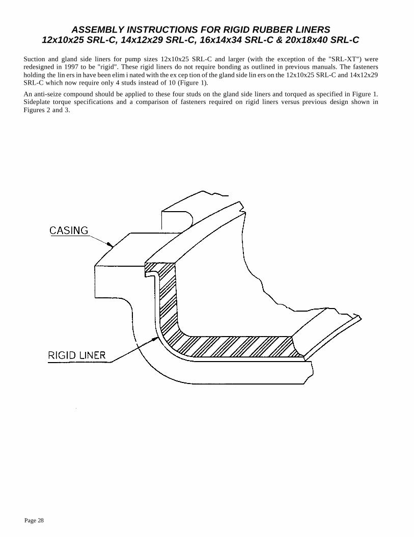
Page 28
ASSEMBLY INSTRUCTIONS FOR RIGID RUBBER LINERS12x10x25 SRL-C, 14x12x29 SRL-C, 16x14x34 SRL-C & 20x18x40 SRL-C
Suc tion and gland side lin ers for pump sizes 12x10x25 SRL-C and larger (with the ex cep tion of the "SRL-XT") werere de signed in 1997 to be "rigid". These rigid lin ers do not re quire bond ing as out lined in pre vi ous man u als. The fas ten ershold ing the lin ers in have been elim i nated with the ex cep tion of the gland side lin ers on the 12x10x25 SRL-C and 14x12x29SRL-C which now re quire only 4 studs in stead of 10 (Fig ure 1).
An anti-seize com pound should be ap plied to these four studs on the gland side lin ers and torqued as spec i fied in Fig ure 1.Sideplate torque spec i fi ca tions and a com par i son of fas ten ers re quired on rigid lin ers ver sus pre vi ous de sign shown inFig ures 2 and 3.
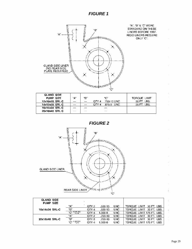
Page 29
FIGURE 2
FIGURE 1
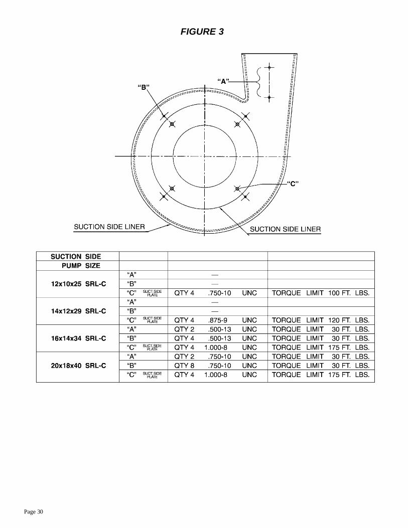
Page 30
FIGURE 3
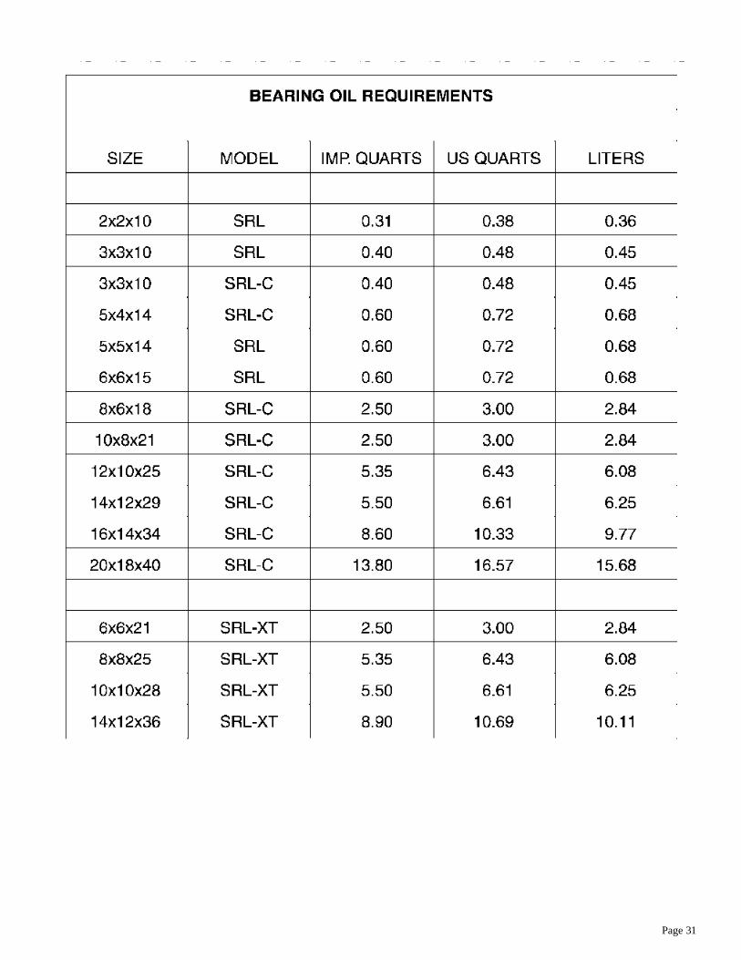
Page 31
