modelocked lasers
DESCRIPTION
lasersTRANSCRIPT

Mode-locked Lasers
How are ultrashort pulses generated?
Mode-locked lasers are most common
Other (rarer) techniques include E-O modulation, modulation instability and compression
An ultrashort pulse requires large bandwidth, this is obtained by having many longitudinal
modes in the cavity lasing simultaneously
However, multi-mode lasing just generates noise unless there is a fixed phase relationship
among the modes, thus the term “mode-locking”.


Generic Elements of Modelocked Lasers
1) Broadband gain medium
2) Cavity
mirrors, provide feedback
3) Output coupler
partially transmissive mirror, provides output
4) Anomalous dispersive element
Compensate normal dispersion in other elements
5) Modelocker
Active: phase modulator
Passive: saturable absorber
gD ML
For the basics of lasers see, for example, Verdeyen “Laser Fundamentals”

Gain Medium
g
Must be supplied with energy – the “pump”
Typical ultrafast lasers are pumped by another laser
Amplifies light by stimulated emission
Requires inversion – more atoms/molecules in the excited state – so that
stimulated emission overcomes absorption
Two categories:
3-level
Inferior – require strong pumping
Example: erbium, ruby
4-level
Preferred
Examples: ti:sapphire, organic dyes
The gain medium always operates in saturation
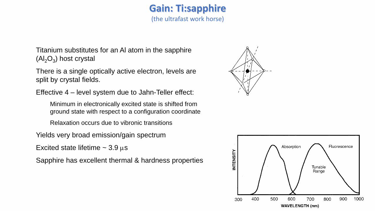
Gain: Ti:sapphire(the ultrafast work horse)
Titanium substitutes for an Al atom in the sapphire
(Al2O3) host crystal
There is a single optically active electron, levels are
split by crystal fields.
Effective 4 – level system due to Jahn-Teller effect:
Minimum in electronically excited state is shifted from
ground state with respect to a configuration coordinate
Relaxation occurs due to vibronic transitions
Yields very broad emission/gain spectrum
Excited state lifetime ~ 3.9 ms
Sapphire has excellent thermal & hardness properties

Other Gain Media
Material Gain Pump Comments
Dyes Various Excimer, Nd: YAG
SH, flashlamp
Messy, limited
lifetime,
toxic/carcinogenic
Diodes Various (~850
best)
Electrical Gain dyanmics
limit minimum
duration
Cr:LiSAF,
Cr:LiCAF
820-880 670 nm diode Poor thermal
properties
Cr:Forsterite 1300-1400 Nd:YAG
Cr:YAG 1500-1600 Nd:YAG Crystals rare
Erbium 1530-1560 980 or 1480 nm
diode
3 - level

General Saturation
General form for saturation of absorption
Propagation through an absorbing material with absorption coefficient a [cm-1]:
Idz
dIa
(gain is simply a < 0)
IIIdz
dI
S
1
0a
Where Is is the “saturation intensity”, i.e. the intensity for which the absorption is reduced to ½
its small signal value.
0.0 0.5 1.0 1.5 2.0 2.5 3.0
0.0
0.2
0.4
0.6
0.8
1.0
aa
0
I/Is
For absorption, Is depends on number of atoms, cross-section and relaxation rate
For gain, it also depends on pump rate

Output coupling
0.00 0.02 0.04 0.06 0.08 0.10
0.00
0.01
0.02
0.03
0.04
0.05
Ou
tpu
t p
ow
er
rela
tive
to
Is
Output coupler transmission
For a CW laser, the optimum output coupling is a trade off between
1) Extracting the power (increasing transmission); and
2) Decreasing the intracavity power because increased loss means gain less saturated
where To is the output coupler transmission, g0 is
small signal gain and L is other losses in the cavity
In the case of a passively mode-locked laser, one must also consider the issue of pulse stability, i.e.
maintaining high enough peak power, this depends on details of the mode-locking mechanism
1
0
0
TL
gTII osout
20
0
LgII
LgLT
smaxout
opto
g0 = 0.1
L = 0.01
The maximum is
In the situation of high cavity Q (low net loss), the output power is approximately

ABCD (Ray) Matrices(lightspeed review)
Represent propagation through optical elements
system matrix is simply product of matrices for individual elements
10
1n
d Propagation through a distance d in a medium with
index of refraction n. [Take care to not double count n.]
11
01
f
A thin lens with focal length f
12
01
R
Reflection from a spherical mirror with radius R. R > 0 for
center of curvature in positive propagation direction
Ray Optics: represent ray by vector:
Gaussian beams: describe transformation of beam parameter
r
r

Propagation of Gaussian beams through optical elements
Characterize a beam by
0izzq
Propagation through an element characterized by matrix is
DC
BA
DCq
BAqq
1
12
znwi
zRzz
zi
zz
z
izzq 2
0
22
0
22
0
111
00
1
12
Lqq
Check for free space1
0 1
L

Beam in resonator must be self-consistent, i.e., the same after one round trip.
Determine the ABCD matrix for one round trip in the resonator
matrix depends on starting point
Solve equation
DCq
BAqq
which gives 2 solutions (using fact that AD-BC =1 for ABCD matrices)
21 1
12 2
D A A D
q B B
Then construct the proper matrix to propagate to other points inside or outside the cavity
Cavity: Basics of Stability I

Cavity: Basics of Stability II
Use ABCD matrices, resonator stable if round-trip matrix satisfies
stable conditionally stablerequires perfect alignment
unstable
20 1
4
A D
Flat mirrors, just free space, A = D = 1, gives conditionally stable
Equality conditionally stable

Astigmatism correctionBrewsters angle is used to minimize loss entering the gain medium 2
1
tann
n
At the same time, the beam is focused into the crystal
Net result is astigmatism [focus different for the two transverse directions]
Use an angled mirror to compensate
cos,
cosff
ff yx
y
x
For Brewster plate of thickness d and index n between two curved mirrors with RoC R
cos
sin112 2
4
24
n
nn
R
dFor 9 mm Ti:Sapph and R = 10 cm, = 9.5o
Kogelnik, Ippen, Dienes and Shank, J. Quantum Electr. 8, 373 (1972)
For dye lasers, full compensation impossible,
cancellation between two astigmatic focii is used

Dispersion Compensation
D
We have discussed the following dispersion compensation elements that can be used in a bulk optics
laser cavity:
Prisms
Dispersion compensating mirrors
In a fiber laser at 1550 nm, the dispersion of the fiber itself can be engineered
Standard “lore”: the net “cold cavity” GVD needs to be slightly anomalous cancels chirp due to
nonlinearity
Not true: “stretched pulse” designs, works when dispersion is “managed”

Mode locker
Active
Electooptic or Acoustooptic
Passive Saturable absorption
Real vs. effective
Slow vs. fast

Active Modelocking
Modulation at cavity repetition rate, either
Amplitude
or
Phase
works…amplitude is fairly intuitive, but phase?
Think in frequency domain, modulation at frequency wm puts sidebands on spaced by wm
If wm matches mode spacing
feed energy from initial CW mode into sidebands, with fixed phase
W
Cavity modes
Limit to minimum pulse duration
mf
g 122ln2 41
2
0
Where
fm is modulation frequency
n is gain bandwidth
is the modulation index
Note bandwidth dependence

Real Saturable Absorption
CW: Atoms relax and can continue to absorb subsequent photons
Pulse: Saturate medium, some photons pass through
Front edge of the pulse preferentially absorbed
Back edge unaffected
Operating intensity depends on saturation of both absorption and gain:
0.0 0.5 1.0 1.5 2.0 2.5 3.0
0.0
0.2
0.4
0.6
0.8
1.0
aa
0, 0
I/Is
Intensity will increase to upper crossing point
Fluctuation required to start lasing
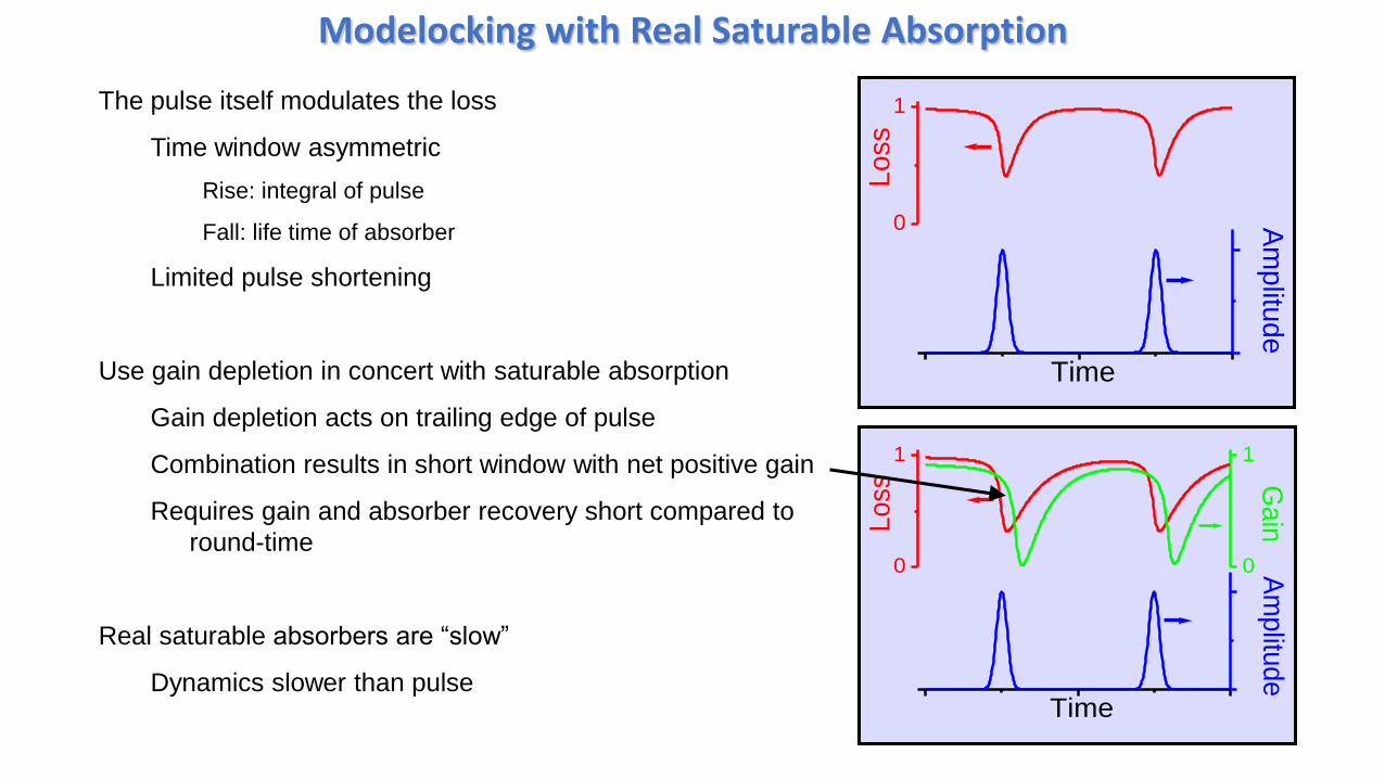
Modelocking with Real Saturable Absorption
The pulse itself modulates the loss
Time window asymmetric
Rise: integral of pulse
Fall: life time of absorber
Limited pulse shortening
Use gain depletion in concert with saturable absorption
Gain depletion acts on trailing edge of pulse
Combination results in short window with net positive gain
Requires gain and absorber recovery short compared to
round-time
Real saturable absorbers are “slow”
Dynamics slower than pulse
0
1A
mp
litud
e
Lo
ss
Time
0
1
0
1
Gain
Am
plitu
de
Loss
Time

Examples of Real Saturable Absorbers1) Dyes – usually a jet
2) Semiconductors – usually incorporated into a mirror
Known as “saturable Bragg reflector” (SBR) or “semiconductor saturable absorber mirror” (SESAM)

Effective Saturable Absorption: Kerr lens
CW
Modelocked
Kerr Lens & Aperture gives increased transmission at high intensity
Increased transmission at high intensity = saturable absorption
Requires biasing alignment away from optimum CW
Misalign cavity, Kerr lens realigns it
Output beam become intensity dependent
GaussianLaser Beam
High Intensity
Gaussian Beam =Gaussian Index Profile =Gradient Index Lens
GaussianLaser Beam
Low Intensity
Kerr Mediumn = n0 + n2I

Effective Saturable Absorption: Nonlinear Polarization Rotation
The nonlinear phase shift from the Kerr effect rotates elliptically polarized light
Due to differential phase shift between components with different
amplitude does not occur for linearly or circularly polarized light
Most easily observed in fiber
Can be used as modelocking mechanism: effective saturable absorber
“Elliptical
Polarizer” -p
late
Nonlinear medium (fiber)
Low IntensityHigh intensity

Initiating Modelocking
Both active modelocking and real saturable absorbers are self starting
Effective (fast) saturable absorbers are not in general
Requires starting mechanism perturbation noise spike
builds up
Stronger self-amplitude modulation makes it easier to start
Almost self starting in some cases (any miniscule perturbation is sufficient)
Can be automated
Or add weak real saturable absorber as starter

Prototypical modelocked Ti:sapphire laser
Put all the pieces together….
Output
coupler High reflectorPump
Ti:Sapphire
crystal
Prisms(Dispersion compensation)