model:lk-p12(non peeler) portable printer system ... · model:lk-p12(non peeler) portable printer...
TRANSCRIPT
MODEL:LK-P12(Non peeler)
Portable Printer
P12(Non peeler) Rev. A 01/15
System Administrator Manual
1
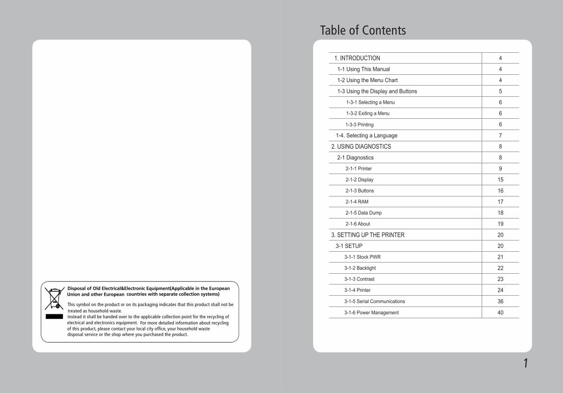
Table of Contents
1. INTRODUCTION 4
1-1 Using This Manual 4
1-2 Using the Menu Chart 4
1-3 Using the Display and Buttons 5
1-3-1 Selecting a Menu 6
1-3-2 Exiting a Menu 6
1-3-3 Printing 6
1-4. Selecting a Language 7
2. USING DIAGNOSTICS 8
2-1 Diagnostics 8
2-1-1 Printer 9
2-1-2 Display 15
2-1-3 Buttons 16
2-1-4 RAM 17
2-1-5 Data Dump 18
2-1-6 About 19
3. SETTING UP THE PRINTER 20
3-1 SETUP 20
3-1-1 Stock PWR 21
3-1-2 Backlight 22
3-1-3 Contrast 23
3-1-4 Printer 24
3-1-5 Serial Communications 36
3-1-6 Power Management 40
32
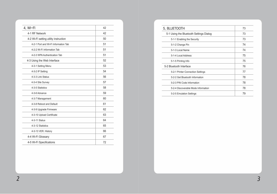
4. WI-FI 42
4-1 RF Network 42
4-2 Wi-Fi setting utility instruction 50
4-2-1 Port and Wi-Fi Information Tab 51
4-2-2 Wi-Fi Information Tab 51
4-2-3 WPA Authentication Tab 51
4-3 Using the Web Interface 52
4-3-1 Setting Menu 53
4-3-2 IP Setting 54
4-3-3 Link Status 56
4-3-4 Site Survey 57
4-3-5 Statistics 58
4-3-6 Advance 59
4-3-7 Management 60
4-3-8 Reboot and Default 61
4-3-9 Upgrade Firmware 62
4-3-10 Upload Certificate 63
4-3-11 Status 64
4-3-12 Statistics 65
4-3-13 VER. History 66
4-4 Wi-Fi Glossary 67
4-5 Wi-Fi Specifications 72
5. BLUETOOTH 73
5-1 Using the Bluetooth Settings Dialog 73
5-1-1 Enabling the Security 73
5-1-2 Change Pin 74
5-1-3 Local Name 74
5-1-4 Local Address 75
5-1-5 Printing Info 75
5-2 Bluetooth Interface 76
5-2-1 Printer Connection Settings 77
5-2-2 Get Bluetooth Information 78
5-2-3 PIN Code Information 78
5-2-4 Discoverable Mode Information 78
5-2-5 Emulation Settings 79
54
1. INTRODUCTION
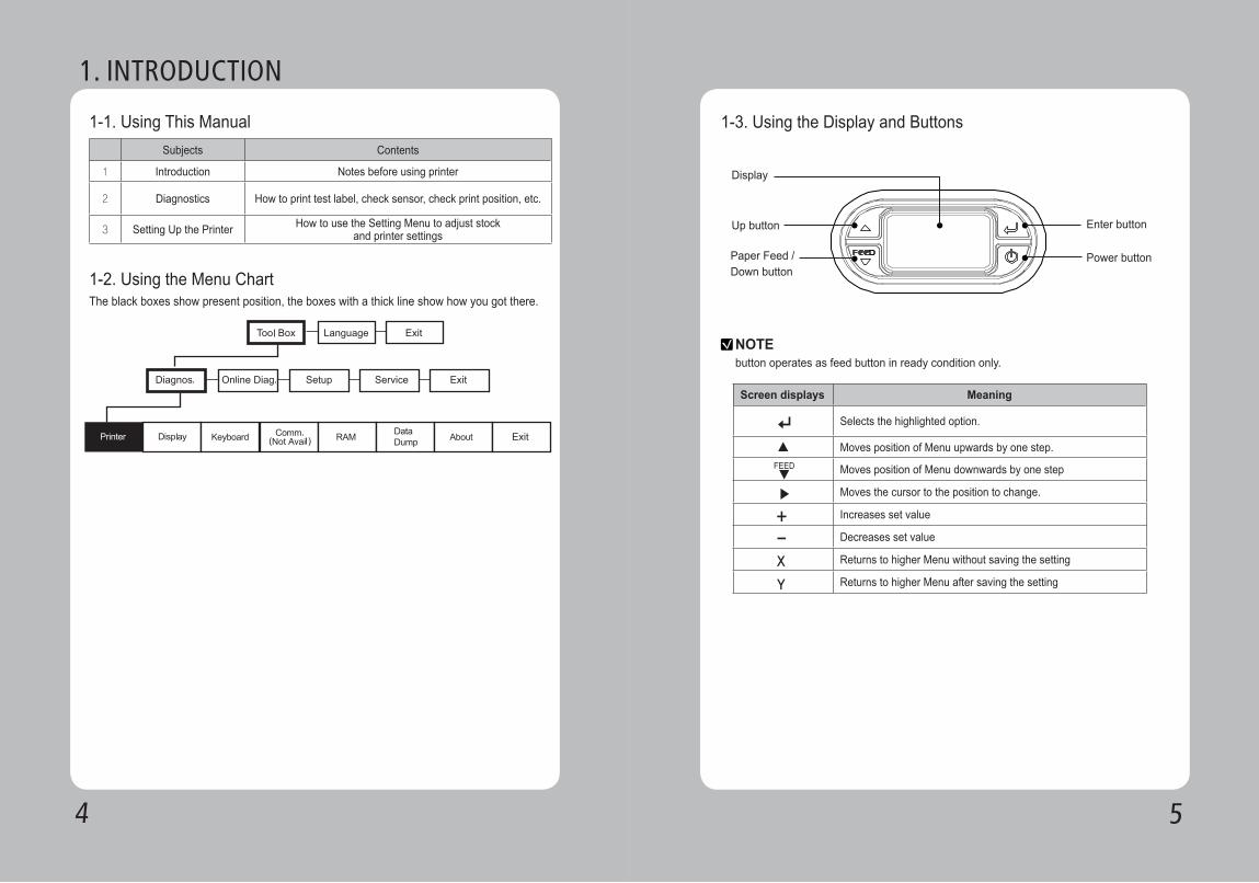
1-1. Using This Manual
1-2. Using the Menu Chart
Subjects Contents
1 Introduction Notes before using printer
2 Diagnostics How to print test label, check sensor, check print position, etc.
3 Setting Up the Printer How to use the Setting Menu to adjust stock and printer settings
The black boxes show present position, the boxes with a thick line show how you got there.
1-3. Using the Display and Buttons
NOTEbutton operates as feed button in ready condition only.
Screen displays Meaning
Selects the highlighted option.
Moves position of Menu upwards by one step.
Moves position of Menu downwards by one step
Moves the cursor to the position to change.
Increases set value
Decreases set value
Returns to higher Menu without saving the setting
Returns to higher Menu after saving the setting
Display
Enter button
Power button
Up button
Paper Feed / Down button
▶
+-X
Y
FEED▼
▲
76
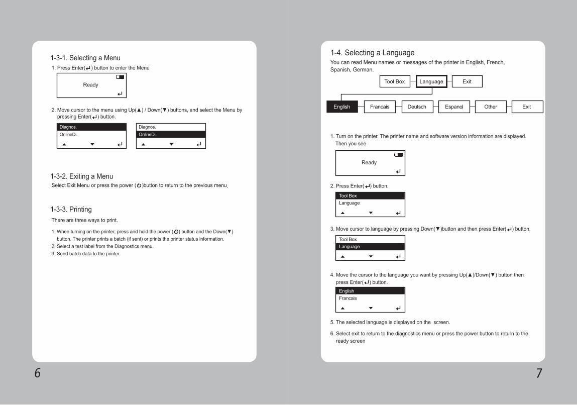
1. Press Enter( ) button to enter the Menu
2. Move cursor to the menu using Up(▲) / Down(▼) buttons, and select the Menu by pressing Enter( ) button.
Select Exit Menu or press the power ( )button to return to the previous menu.
There are three ways to print.
1. When turning on the printer, press and hold the power ( ) button and the Down(▼) button. The printer prints a batch (if sent) or prints the printer status information. 2. Select a test label from the Diagnostics menu.3. Send batch data to the printer.
1-3-1. Selecting a Menu
1-3-2. Exiting a Menu
1-3-3. Printing
1-4. Selecting a LanguageYou can read Menu names or messages of the printer in English, French, Spanish, German.
1. Turn on the printer. The printer name and software version information are displayed. Then you see
2. Press Enter( ) button.
3. Move cursor to language by pressing Down(▼)button and then press Enter( ) button.
4. Move the cursor to the language you want by pressing Up(▲)/Down(▼) button then press Enter( ) button.
5. The selected language is displayed on the screen.
6. Select exit to return to the diagnostics menu or press the power button to return to the ready screen
98
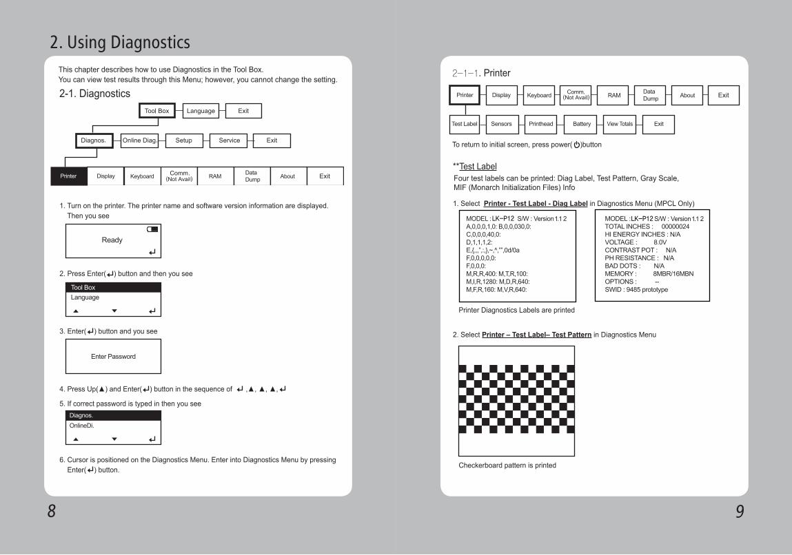
2-1. Diagnostics
This chapter describes how to use Diagnostics in the Tool Box.You can view test results through this Menu; however, you cannot change the setting.
1. Turn on the printer. The printer name and software version information are displayed. Then you see
2. Press Enter( ) button and then you see
3. Enter( ) button and you see
5. If correct password is typed in then you see
4. Press Up(▲) and Enter( ) button in the sequence of ,▲, ▲, ▲,
6. Cursor is positioned on the Diagnostics Menu. Enter into Diagnostics Menu by pressing Enter( ) button.
2. Using Diagnostics
2-1-1. Printer
To return to initial screen, press power( )button
Four test labels can be printed: Diag Label, Test Pattern, Gray Scale, MIF (Monarch Initialization Files) Info
**Test Label
1. Select Printer - Test Label - Diag Label in Diagnostics Menu (MPCL Only)
2. Select Printer – Test Label– Test Pattern in Diagnostics Menu
Checkerboard pattern is printed
Printer Diagnostics Labels are printed
LK-P12 LK-P12
1110
Gray Scale printed
MIF Info printed
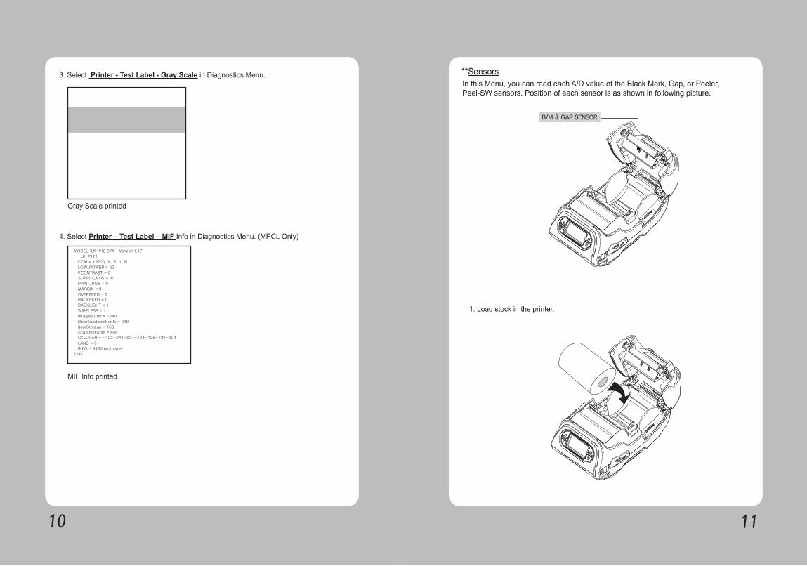
3. Select Printer - Test Label - Gray Scale in Diagnostics Menu.
4. Select Printer – Test Label – MIF Info in Diagnostics Menu. (MPCL Only)
In this Menu, you can read each A/D value of the Black Mark, Gap, or Peeler, Peel-SW sensors. Position of each sensor is as shown in following picture.
**Sensors
1. Load stock in the printer.
B/M & GAP SENSOR
1312
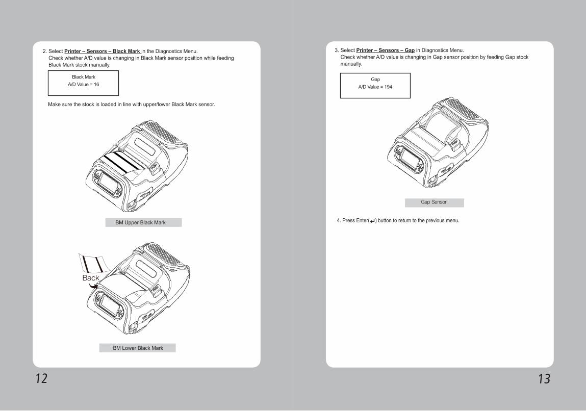
2. Select Printer – Sensors – Black Mark in the Diagnostics Menu. Check whether A/D value is changing in Black Mark sensor position while feeding Black Mark stock manually.
Make sure the stock is loaded in line with upper/lower Black Mark sensor.
3. Select Printer – Sensors – Gap in Diagnostics Menu. Check whether A/D value is changing in Gap sensor position by feeding Gap stock manually.
4. Press Enter( ) button to return to the previous menu. BM Upper Black Mark
BM Lower Black Mark
Gap Sensor
1514
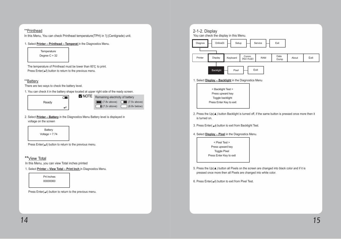
1. Select Printer – Printhead – Temperat in the Diagnostics Menu.
1. You can check it in the battery shape located at upper right side of the ready screen.
In this Menu, You can check Printhead temperature(TPH) in ℃(Centigrade) unit.
The temperature of Printhead must be lower than 60℃ to print. Press Enter( ) button to return to the previous menu.
**Printhead
There are two ways to check the battery level.
2. Select Printer – Battery in the Diagnostics Menu Battery level is displayed in voltage on the screen
**Battery
NOTE(7.8v above) (7.5v above)(7.2v above) (6.8v below)
Press Enter( ) button to return to the previous menu.
1. Select Printer – View Total – Print Inch in Diagnostics Menu.
In this Menu, you can view Total inches printed **View Total
Press Enter( ) button to return to the previous menu.
Remaining electricity of battery
2-1-2. Display
1. Select Display – Backlight in the Diagnostics Menu
You can check the display in this Menu.
2. Press the Up(▲) button Backlight is turned off, if the same button is pressed once more then it is turned on.
3. Press Enter( ) button to exit from Backlight Test.
4. Select Display – Pixel in the Diagnostics Menu.
5. Press the Up(▲) button all Pixels on the screen are changed into black color and if it is pressed once more then all Pixels are changed into white color.
6. Press Enter( ) button to exit from Pixel Test.
1716
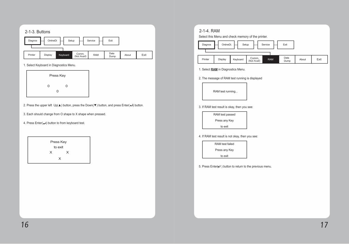
2-1-3. Buttons
1. Select Keyboard in Diagnostics Menu.
2. Press the upper left Up(▲) button, press the Down(▼) button, and press Enter( ) button.
3. Each should change from O shape to X shape when pressed.
4. Press Enter( ) button to from keyboard test.
2-1-4. RAMSelect this Menu and check memory of the printer.
1. Select RAM in Diagnostics Menu.
2. The message of RAM test running is displayed
3. If RAM test result is okay, then you see:
4. If RAM test result is not okay, then you see:
5. Press Enter( ) button to return to the previous menu.
1918
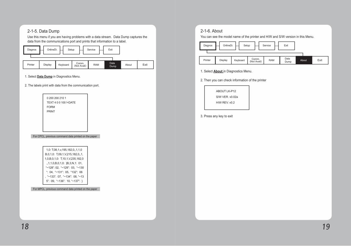
2-1-5. Data DumpUse this menu if you are having problems with a data stream. Data Dump captures the data from the communications port and prints that information to a label.
For CPCL, previous command data printed on the paper
For MPCL, previous command data printed on the paper
1. Select Data Dump in Diagnostics Menu.
2. The labels print with data from the communication port.
2-1-6. AboutYou can see the model name of the printer and H/W and S/W version in this Menu.
1. Select About in Diagnostics Menu.
2. Then you can check information of the printer
3. Press any key to exit
2120
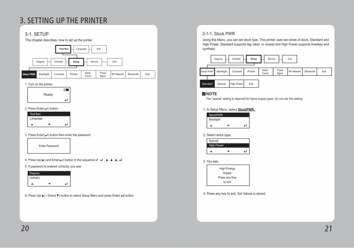
3. SETTING UP THE PRINTER
3-1. SETUPThis chapter describes, how to set up the printer
1. Turn on the printer.
2. Press Enter( ) button.
3. Press Enter( ) button then enter the password.
5. If password is entered correctly, you see:
6. Press Up(▲) / Down(▼) button to select Setup Menu and press Enter( ) button
4. Press Up(▲) and Enter( ) button in the sequence of , ▲, ▲, ▲,
3-1-1. Stock PWRUsing this Menu, you can set stock type. This printer uses two kinds of stock, Standard and High Power. Standard supports tag, label, or receipt and High Power supports linerless and synthetic
1. In Setup Menu, select StockPWR.
2. Select stock type.
3. You see:.
4. Press any key to exit. Set Values is stored.
NOTEThe “special” setting is reserved for future supply types. Do not use this setting.

2322
3-1-2. BacklightThis Menu can activate or deactivate Backlight of LCD.
1. In Setup Menu, select Backlight.
2. Select Disable or Enable
3. You see:.
4. Press any key to exit. Set Values is stored.
3-1-3. ContrastThis Menu sets Contrast of LCD
1. Select Contrast in Setup Menu.
2. Press the Up(▲) button or Down(▼) button to adjust the contrast.
3. Press enter button ( ) to save and exit
+( ) -( )
2524
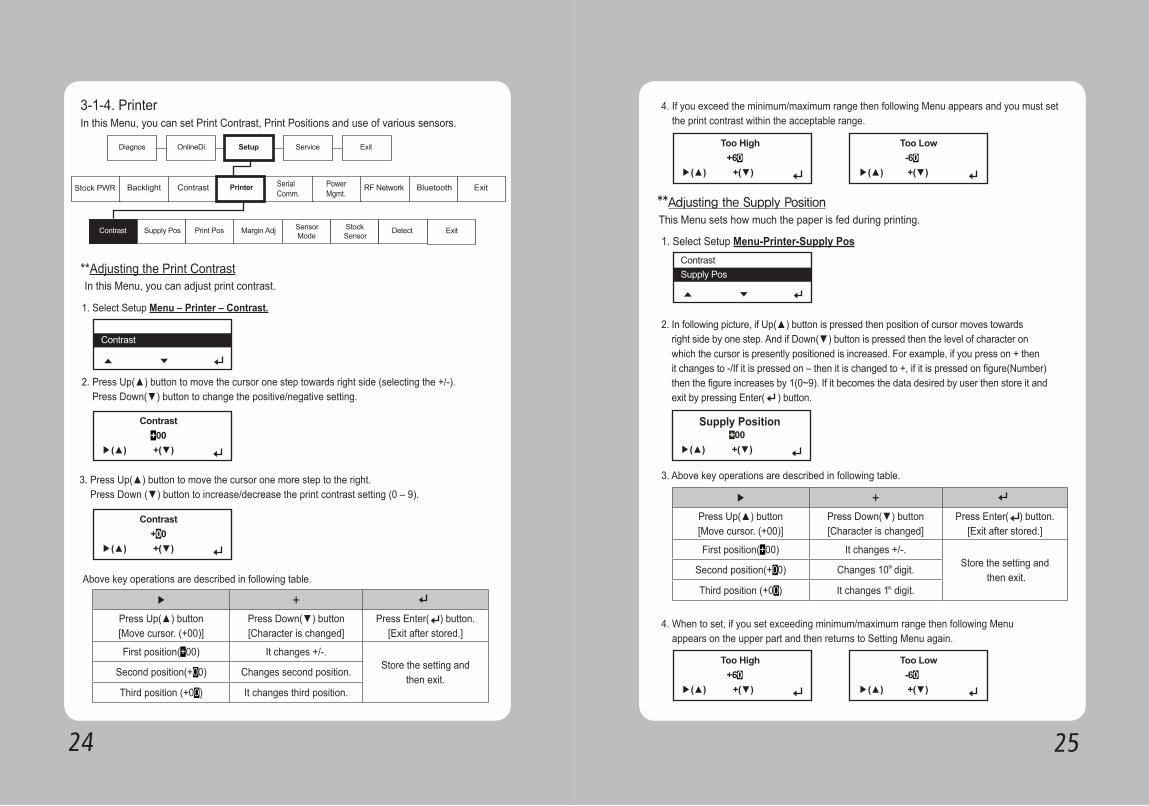
▶ +
Press Up(▲) button[Move cursor. (+00)]
Press Down(▼) button[Character is changed]
Press Enter( ) button.[Exit after stored.]
First position(+00) It changes +/-.Store the setting and
then exit.Second position(+00) Changes second position.
Third position (+00) It changes third position.
3-1-4. PrinterIn this Menu, you can set Print Contrast, Print Positions and use of various sensors.
In this Menu, you can adjust print contrast.
1. Select Setup Menu – Printer – Contrast.
Above key operations are described in following table.
2. Press Up(▲) button to move the cursor one step towards right side (selecting the +/-). Press Down(▼) button to change the positive/negative setting.
3. Press Up(▲) button to move the cursor one more step to the right. Press Down (▼) button to increase/decrease the print contrast setting (0 – 9).
**Adjusting the Print Contrast
4. If you exceed the minimum/maximum range then following Menu appears and you must set the print contrast within the acceptable range.
1. Select Setup Menu-Printer-Supply Pos
3. Above key operations are described in following table.
4. When to set, if you set exceeding minimum/maximum range then following Menu appears on the upper part and then returns to Setting Menu again.
This Menu sets how much the paper is fed during printing.**Adjusting the Supply Position
2. In following picture, if Up(▲) button is pressed then position of cursor moves towards right side by one step. And if Down(▼) button is pressed then the level of character on which the cursor is presently positioned is increased. For example, if you press on + then it changes to -/If it is pressed on – then it is changed to +, if it is pressed on figure(Number) then the figure increases by 1(0~9). If it becomes the data desired by user then store it and exit by pressing Enter( ) button.
▶ +
Press Up(▲) button[Move cursor. (+00)]
Press Down(▼) button[Character is changed]
Press Enter( ) button.[Exit after stored.]
First position(+00) It changes +/-.Store the setting and
then exit.Second position(+00) Changes 10 digit.
Third position (+00) It changes 1 digit.
th
st
2726
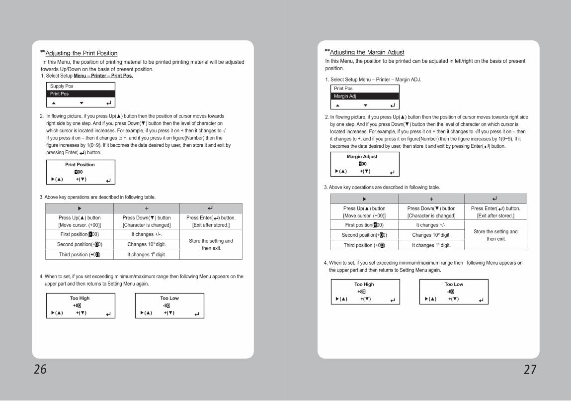
4. When to set, if you set exceeding minimum/maximum range then following Menu appears on the upper part and then returns to Setting Menu again.
1. Select Setup Menu – Printer – Print Pos.
3. Above key operations are described in following table.
In this Menu, the position of printing material to be printed printing material will be adjusted towards Up/Down on the basis of present position.
**Adjusting the Print Position
2. In flowing picture, if you press Up(▲) button then the position of cursor moves towards right side by one step. And if you press Down(▼) button then the level of character on which cursor is located increases. For example, if you press it on + then it changes to -/ If you press it on – then it changes to +, and if you press it on figure(Number) then the figure increases by 1(0~9). If it becomes the data desired by user, then store it and exit by pressing Enter( ) button.
▶ +
Press Up(▲) button[Move cursor. (+00)]
Press Down(▼) button[Character is changed]
Press Enter( ) button.[Exit after stored.]
First position(+00) It changes +/-.Store the setting and
then exit.Second position(+00) Changes 10 digit.
Third position (+00) It changes 1 digit.
th
st
4. When to set, if you set exceeding minimum/maximum range then following Menu appears on the upper part and then returns to Setting Menu again.
1. Select Setup Menu – Printer – Margin ADJ.
3. Above key operations are described in following table.
In this Menu, the position to be printed can be adjusted in left/right on the basis of present position.
**Adjusting the Margin Adjust
2. In flowing picture, if you press Up(▲) button then the position of cursor moves towards right side by one step. And if you press Down(▼) button then the level of character on which cursor is located increases. For example, if you press it on + then it changes to -/If you press it on – then it changes to +, and if you press it on figure(Number) then the figure increases by 1(0~9). If it becomes the data desired by user, then store it and exit by pressing Enter( ) button.
▶ +
Press Up(▲) button[Move cursor. (+00)]
Press Down(▼) button[Character is changed]
Press Enter( ) button.[Exit after stored.]
First position(+00) It changes +/-.Store the setting and
then exit.Second position(+00) Changes 10 digit.
Third position (+00) It changes 1 digit.
th
st
2928
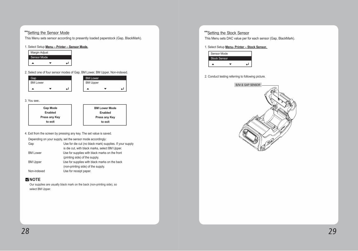
Depending on your supply, set the sensor mode accordingly:Gap Use for die cut (no black mark) supplies. If your supply is die cut, with black marks, select BM Upper.BM Lower Use for supplies with black marks on the front (printing side) of the supply.BM Upper Use for supplies with black marks on the back (non-printing side) of the supply.Non-indexed Use for receipt paper.
1. Select Setup Menu – Printer – Sensor Mode.
2. Select one of four sensor modes of Gap, BM Lower, BM Upper, Non-indexed.
3. You see:.
4. Exit from the screen by pressing any key. The set value is saved.
This Menu sets sensor according to presently loaded paperstock (Gap, BlackMark).**Setting the Sensor Mode
NOTEOur supplies are usually black mark on the back (non-printing side), soselect BM Upper.
1. Select Setup Menu- Printer – Stock Sensor.
2. Conduct testing referring to following picture.
This Menu sets DAC value per for each sensor (Gap, BlackMark).**Setting the Stock Sensor
B/M & GAP SENSOR
3130
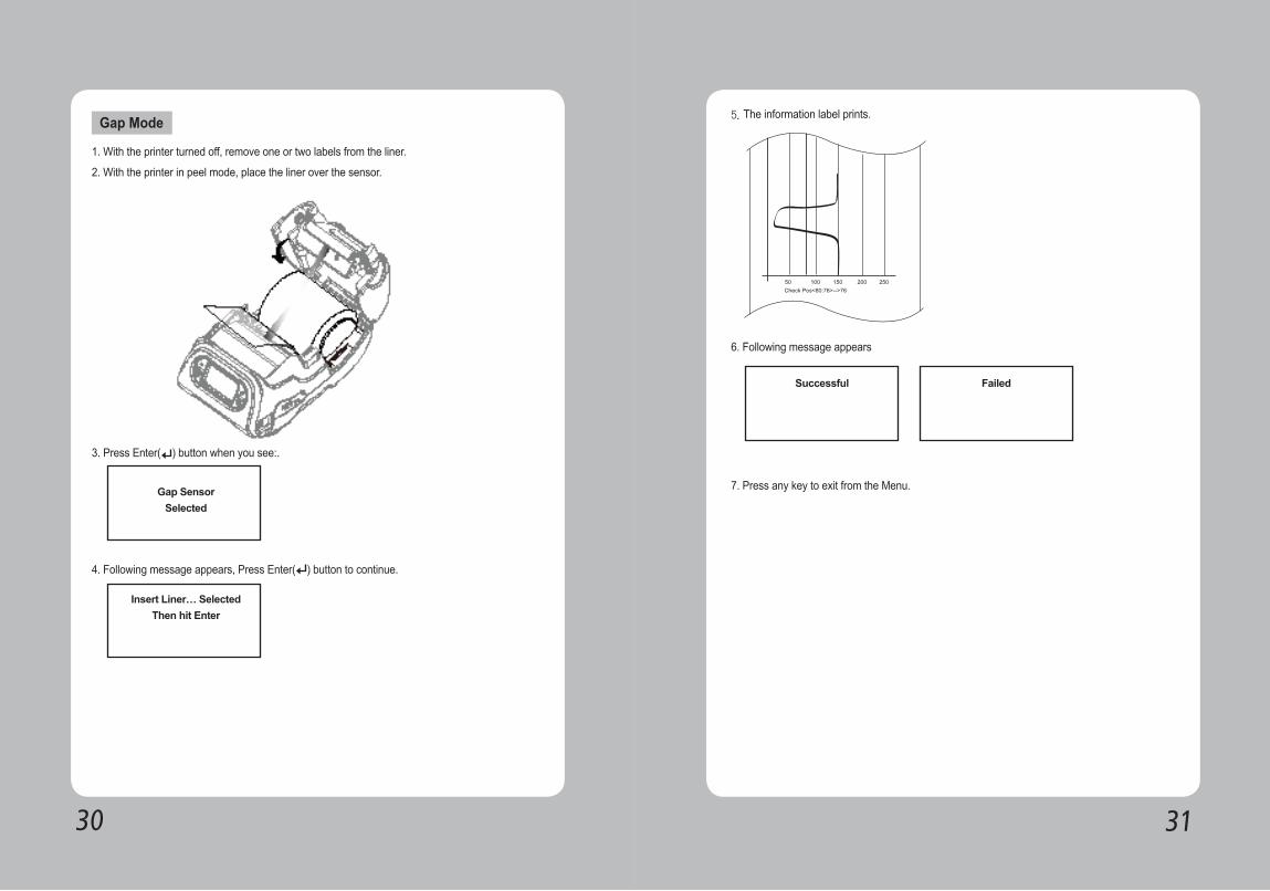
1. With the printer turned off, remove one or two labels from the liner.
2. With the printer in peel mode, place the liner over the sensor.
3. Press Enter( ) button when you see:.
4. Following message appears, Press Enter( ) button to continue.
Gap Mode 5. The information label prints.
6. Following message appears
7. Press any key to exit from the Menu.
3332
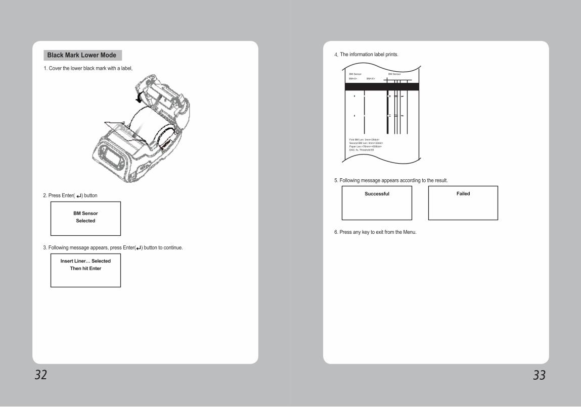
1. Cover the lower black mark with a label,
2. Press Enter( ) button
3. Following message appears, press Enter( ) button to continue.
Black Mark Lower Mode 4. The information label prints.
5. Following message appears according to the result.
6. Press any key to exit from the Menu.
3534
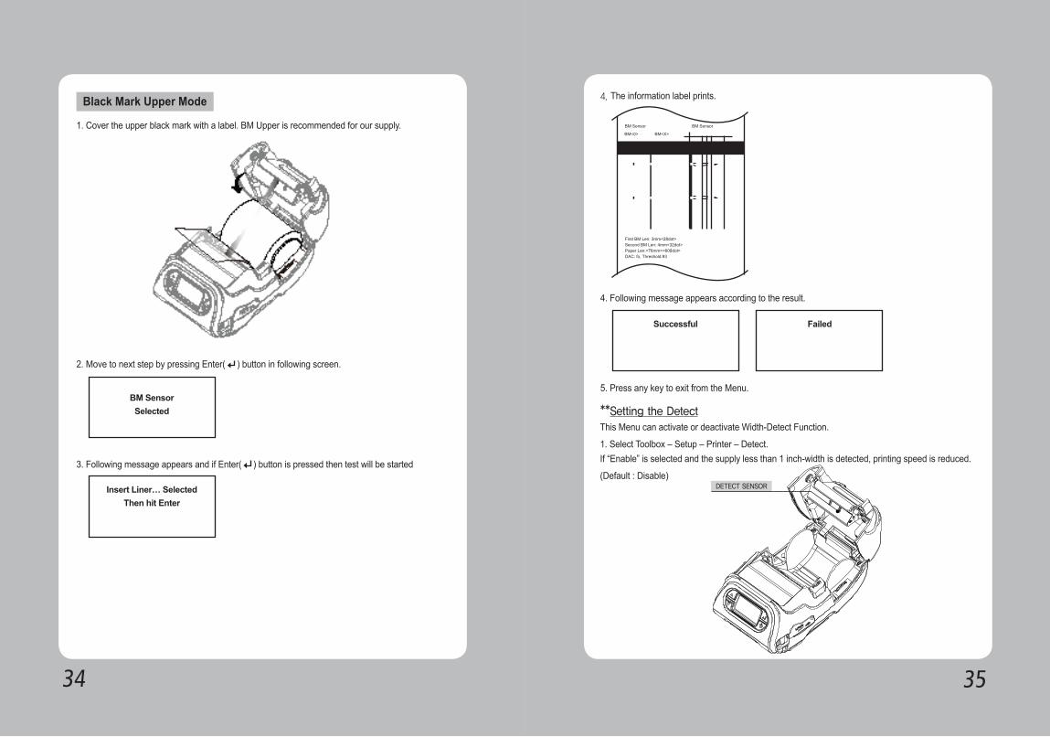
1. Cover the upper black mark with a label. BM Upper is recommended for our supply.
2. Move to next step by pressing Enter( ) button in following screen.
3. Following message appears and if Enter( ) button is pressed then test will be started
Black Mark Upper Mode 4. The information label prints.
4. Following message appears according to the result.
5. Press any key to exit from the Menu.
This Menu can activate or deactivate Width-Detect Function.
1. Select Toolbox – Setup – Printer – Detect.If “Enable” is selected and the supply less than 1 inch-width is detected, printing speed is reduced.
(Default : Disable)
**Setting the Detect
DETECT SENSOR
3736
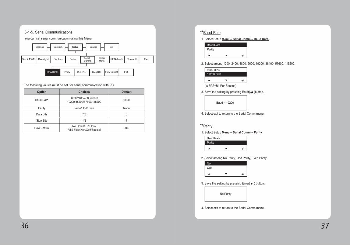
The following values must be set for serial communication with PC.
3-1-5. Serial CommunicationsYou can set serial communication using this Menu.
Option Choices Defualt
Baud Rate 1200/2400/4800/9600/19200/38400/57600/115200 9600
Parity None/Odd/Even None
Data Bits 7/8 8
Stop Bits 1/2 1
Flow Control No Flow/DTR Flow/RTS Flow/Xon/Xoff/Special DTR
1. Select Setup Menu – Serial Comm – Baud Rate.
1. Select Setup Menu – Serial Comm – Parity.
2. Select among No Parity, Odd Parity, Even Parity.
3. Save the setting by pressing Enter( ) button.
4. Select exit to return to the Serial Comm menu.
2. Select among 1200, 2400, 4800, 9600, 19200, 38400, 57600, 115200.
4. Select exit to return to the Serial Comm menu.
3. Save the setting by pressing Enter( )button.
**Baud Rate
**Parity
(※BPS=Bit Per Second)
3938
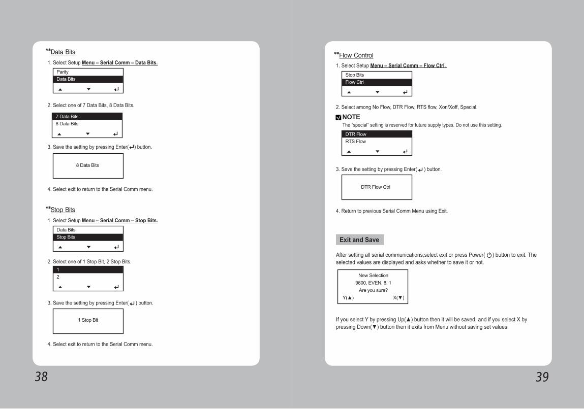
1. Select Setup Menu – Serial Comm – Data Bits.
1. Select Setup Menu – Serial Comm – Stop Bits.
2. Select one of 7 Data Bits, 8 Data Bits.
2. Select one of 1 Stop Bit, 2 Stop Bits.
3. Save the setting by pressing Enter( ) button.
3. Save the setting by pressing Enter( ) button.
4. Select exit to return to the Serial Comm menu.
4. Select exit to return to the Serial Comm menu.
**Data Bits
**Stop Bits
1. Select Setup Menu – Serial Comm – Flow Ctrl.
2. Select among No Flow, DTR Flow, RTS flow, Xon/Xoff, Special.
3. Save the setting by pressing Enter( ) button.
4. Return to previous Serial Comm Menu using Exit.
After setting all serial communications,select exit or press Power( ) button to exit. The selected values are displayed and asks whether to save it or not.
If you select Y by pressing Up(▲) button then it will be saved, and if you select X by pressing Down(▼) button then it exits from Menu without saving set values.
**Flow Control
Exit and Save
NOTEThe “special” setting is reserved for future supply types. Do not use this setting.
4140
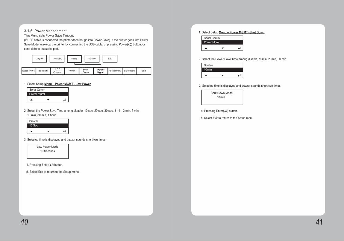
1. Select Setup Menu – Power MGMT - Low Power
2. Select the Power Save Time among disable, 10 sec, 20 sec, 30 sec, 1 min, 2 min, 5 min, 10 min, 30 min, 1 hour.
3. Selected time is displayed and buzzer sounds short two times.
4. Pressing Enter( ) button.
5. Select Exit to return to the Setup menu.
3-1-6. Power ManagementThis Menu sets Power Save Timeout. (If USB cable is connected the printer does not go into Power Save). If the printer goes into Power Save Mode, wake-up the printer by connecting the USB cable, or pressing Power( ) button, or send data to the serial port.
1. Select Setup Menu – Power MGMT -Shut Down
2. Select the Power Save Time among disable, 10min, 20min, 30 min
3. Selected time is displayed and buzzer sounds short two times.
4. Pressing Enter( ) button.
5. Select Exit to return to the Setup menu.
min
minShut Down Mode
4342
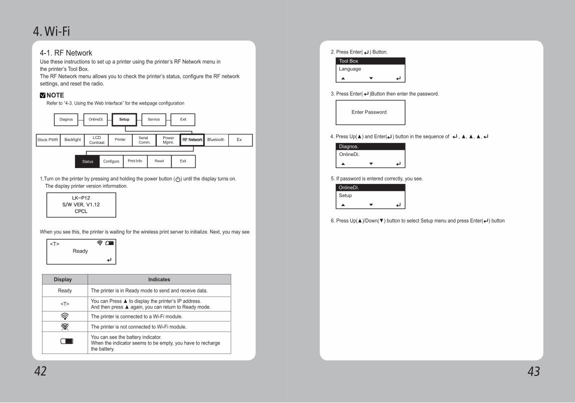
4-1. RF NetworkUse these instructions to set up a printer using the printer’s RF Network menu in the printer’s Tool Box.The RF Network menu allows you to check the printer’s status, configure the RF networksettings, and reset the radio.
NOTERefer to “4-3. Using the Web Interface” for the webpage configuration
1.Turn on the printer by pressing and holding the power button ( ) until the display turns on. The display printer version information.
When you see this, the printer is waiting for the wireless print server to initialize. Next, you may see
Display Indicates
Ready The printer is in Ready mode to send and receive data.
<T> You can Press ▲ to display the printer’s IP address. And then press ▲ again, you can return to Ready mode.
The printer is connected to a Wi-Fi module.
The printer is not connected to Wi-Fi module.
You can see the battery indicator. When the indicator seems to be empty, you have to recharge the battery.
4. Wi-Fi
LK-P12S/W VER. V1.12
CPCL
2. Press Enter( ) Button.
3. Press Enter( )Button then enter the password.
5. If password is entered correctly, you see.
6. Press Up(▲)/Down(▼) button to select Setup menu and press Enter( ) button
4. Press Up(▲) and Enter( ) button in the sequence of , ▲, ▲, ▲,
4544
To check the printer’s network status, use this menu.To exit, press at any time.
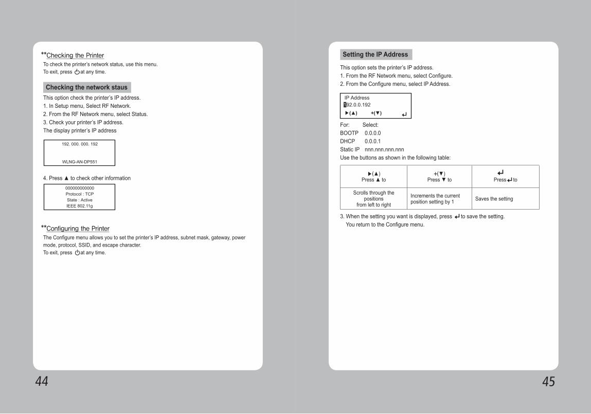
The Configure menu allows you to set the printer’s IP address, subnet mask, gateway, power mode, protocol, SSID, and escape character.To exit, press at any time.
**Checking the Printer
**Configuring the Printer
This option check the printer’s IP address.1. In Setup menu, Select RF Network.2. From the RF Network menu, select Status.3. Check your printer’s IP address.The display printer’s IP address
4. Press ▲ to check other information
Checking the network staus
This option sets the printer’s IP address.1. From the RF Network menu, select Configure.2. From the Configure menu, select IP Address.
Setting the IP Address
For: Select:BOOTP 0.0.0.0DHCP 0.0.0.1Static IP nnn.nnn.nnn.nnnUse the buttons as shown in the following table:
▶(▲)
Press ▲ to+(▼)
Press ▼ to1
Press to
Scrolls through the positions
from left to rightIncrements the currentposition setting by 1 Saves the setting
3. When the setting you want is displayed, press to save the setting. You return to the Configure menu.
4746
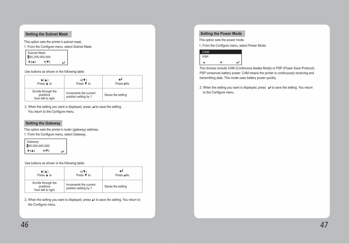
Setting the Subnet Mask
Setting the Gateway
This option sets the printer’s subnet mask.1. From the Configure menu, select Subnet Mask.
This option sets the printer’s router (gateway) address.1. From the Configure menu, select Gateway.
Use buttons as shown in the following table:
Use buttons as shown in the following table:
2. When the setting you want is displayed, press to save the setting. You return to the Configure menu.
▶(▲)
Press ▲ to+(▼)
Press ▼ to1
Press to
Scrolls through the positions
from left to rightIncrements the currentposition setting by 1 Saves the setting
▶(▲)
Press ▲ to+(▼)
Press ▼ to1
Press to
Scrolls through the positions
from left to rightIncrements the currentposition setting by 1 Saves the setting
2. When the setting you want is displayed, press to save the setting. You return to the Configure menu.
Setting the Power Mode This option sets the power mode.1. From the Configure menu, select Power Mode.
The choices include CAM (Continuous Awake Mode) or PSP (Power Save Protocol). PSP conserves battery power. CAM means the printer is continuously receiving and transmitting data. This mode uses battery power quickly.
2. When the setting you want is displayed, press to save the setting. You return to the Configure menu.
4948
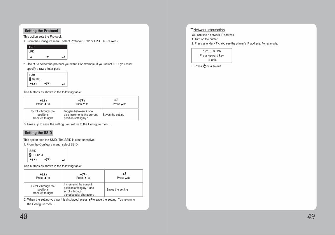
Setting the Protocol
Setting the SSID
This option sets the Protocol.1. From the Configure menu, select Protocol : TCP or LPD. (TCP Fixed)
This option sets the SSID. The SSID is case-sensitive.1. From the Configure menu, select SSID.
2. Use ▼ to select the protocol you want. For example, if you select LPD, you must specify a raw printer port:
Use buttons as shown in the following table:
Use buttons as shown in the following table:
▶(▲)
Press ▲ to+(▼)
Press ▼ to1
Press to
Scrolls through the positions
from left to right
Toggles between + or –also increments the currentposition setting by 1
Saves the setting
▶(▲)
Press ▲ to+(▼)
Press ▼ to1
Press to
Scrolls through the positions
from left to right
Increments the currentposition setting by 1 andscrolls throughalpha/special characters
Saves the setting
3. Press to save the setting. You return to the Configure menu.
2. When the setting you want is displayed, press to save the setting. You return to the Configure menu.
You can see a network IP address. 1. Turn on the printer.2. Press ▲ under <T>. You see the printer’s IP address. For example,
3. Press or ▲ to exit.
**Network Information
5150
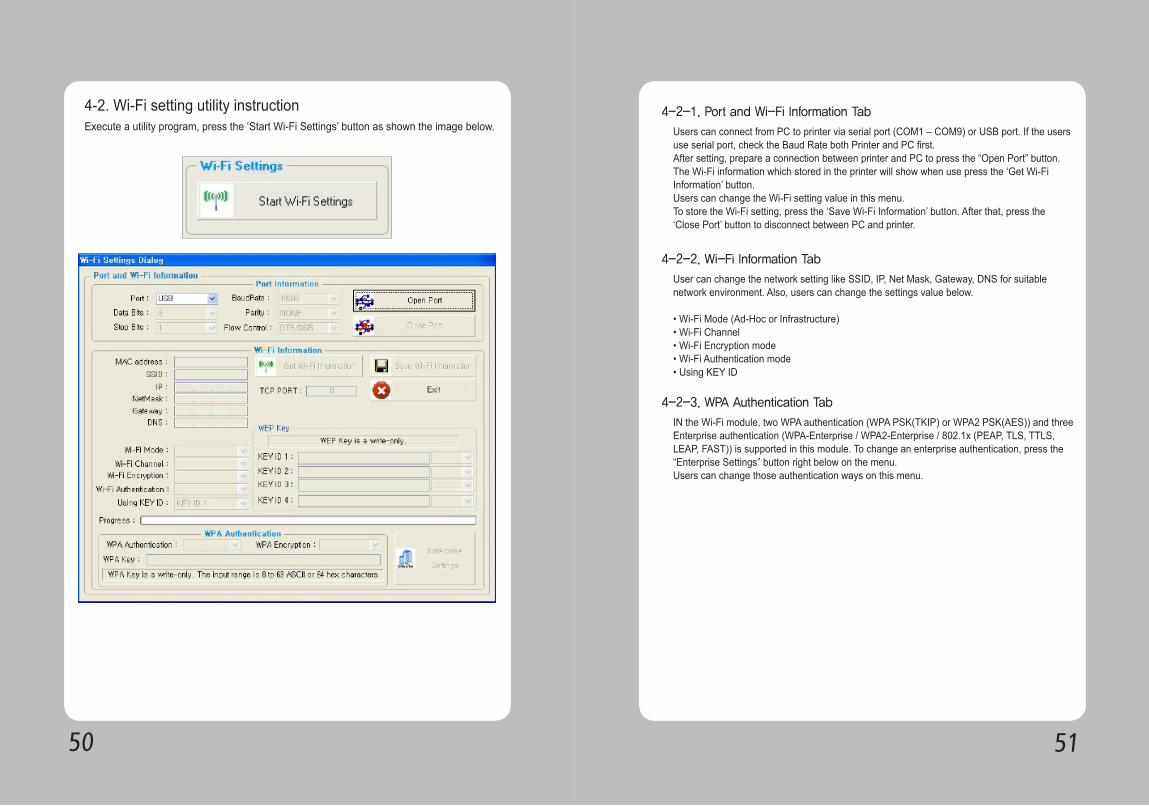
4-2. Wi-Fi setting utility instructionExecute a utility program, press the ‘Start Wi-Fi Settings’ button as shown the image below.
4-2-1. Port and Wi-Fi Information Tab
4-2-2. Wi-Fi Information Tab
4-2-3. WPA Authentication Tab
Users can connect from PC to printer via serial port (COM1 – COM9) or USB port. If the users use serial port, check the Baud Rate both Printer and PC first.After setting, prepare a connection between printer and PC to press the “Open Port” button. The Wi-Fi information which stored in the printer will show when use press the ‘Get Wi-Fi Information’ button.Users can change the Wi-Fi setting value in this menu. To store the Wi-Fi setting, press the ‘Save Wi-Fi Information’ button. After that, press the ‘Close Port’ button to disconnect between PC and printer.
User can change the network setting like SSID, IP, Net Mask, Gateway, DNS for suitable network environment. Also, users can change the settings value below.
• Wi-Fi Mode (Ad-Hoc or Infrastructure)• Wi-Fi Channel • Wi-Fi Encryption mode• Wi-Fi Authentication mode• Using KEY ID
IN the Wi-Fi module, two WPA authentication (WPA PSK(TKIP) or WPA2 PSK(AES)) and three Enterprise authentication (WPA-Enterprise / WPA2-Enterprise / 802.1x (PEAP, TLS, TTLS, LEAP, FAST)) is supported in this module. To change an enterprise authentication, press the “Enterprise Settings” button right below on the menu.Users can change those authentication ways on this menu.
5352
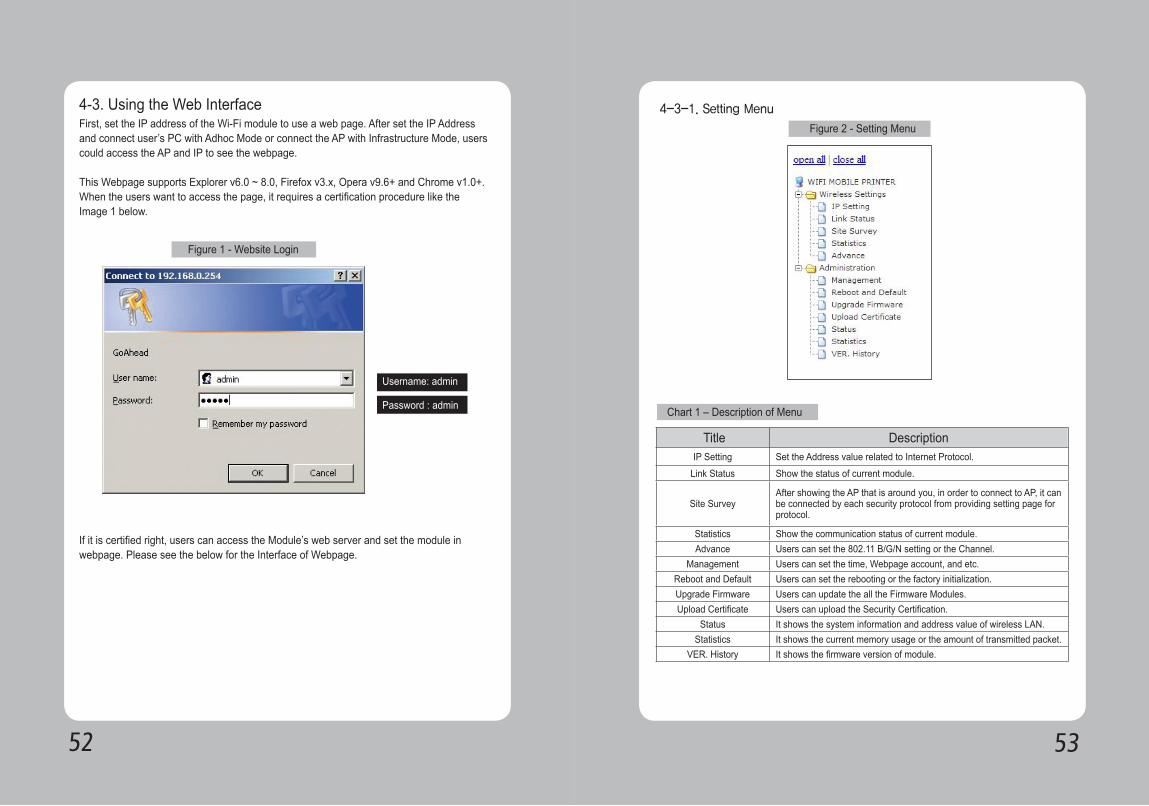
4-3. Using the Web InterfaceFirst, set the IP address of the Wi-Fi module to use a web page. After set the IP Address and connect user’s PC with Adhoc Mode or connect the AP with Infrastructure Mode, users could access the AP and IP to see the webpage.
This Webpage supports Explorer v6.0 ~ 8.0, Firefox v3.x, Opera v9.6+ and Chrome v1.0+. When the users want to access the page, it requires a certification procedure like the Image 1 below.
If it is certified right, users can access the Module’s web server and set the module in webpage. Please see the below for the Interface of Webpage.
Figure 1 - Website Login
Username: admin
Password : admin
Figure 2 - Setting Menu
Chart 1 – Description of Menu
Title DescriptionIP Setting Set the Address value related to Internet Protocol.
Link Status Show the status of current module.
Site SurveyAfter showing the AP that is around you, in order to connect to AP, it can be connected by each security protocol from providing setting page for protocol.
Statistics Show the communication status of current module.Advance Users can set the 802.11 B/G/N setting or the Channel.
Management Users can set the time, Webpage account, and etc. Reboot and Default Users can set the rebooting or the factory initialization.Upgrade Firmware Users can update the all the Firmware Modules. Upload Certificate Users can upload the Security Certification.
Status It shows the system information and address value of wireless LAN. Statistics It shows the current memory usage or the amount of transmitted packet.
VER. History It shows the firmware version of module.
4-3-1. Setting Menu
5554
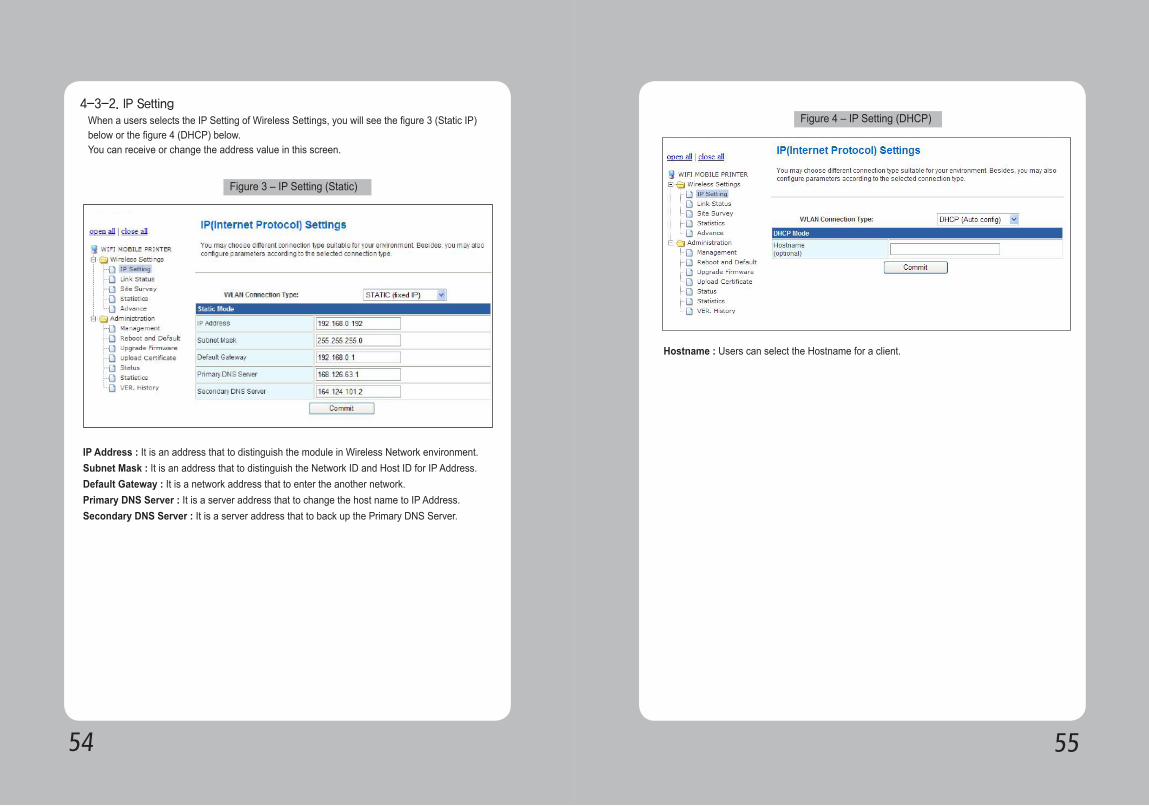
4-3-2. IP Setting When a users selects the IP Setting of Wireless Settings, you will see the figure 3 (Static IP) below or the figure 4 (DHCP) below.You can receive or change the address value in this screen.
IP Address : It is an address that to distinguish the module in Wireless Network environment. Subnet Mask : It is an address that to distinguish the Network ID and Host ID for IP Address. Default Gateway : It is a network address that to enter the another network. Primary DNS Server : It is a server address that to change the host name to IP Address. Secondary DNS Server : It is a server address that to back up the Primary DNS Server.
Figure 3 – IP Setting (Static)
Hostname : Users can select the Hostname for a client.
Figure 4 – IP Setting (DHCP)
5756
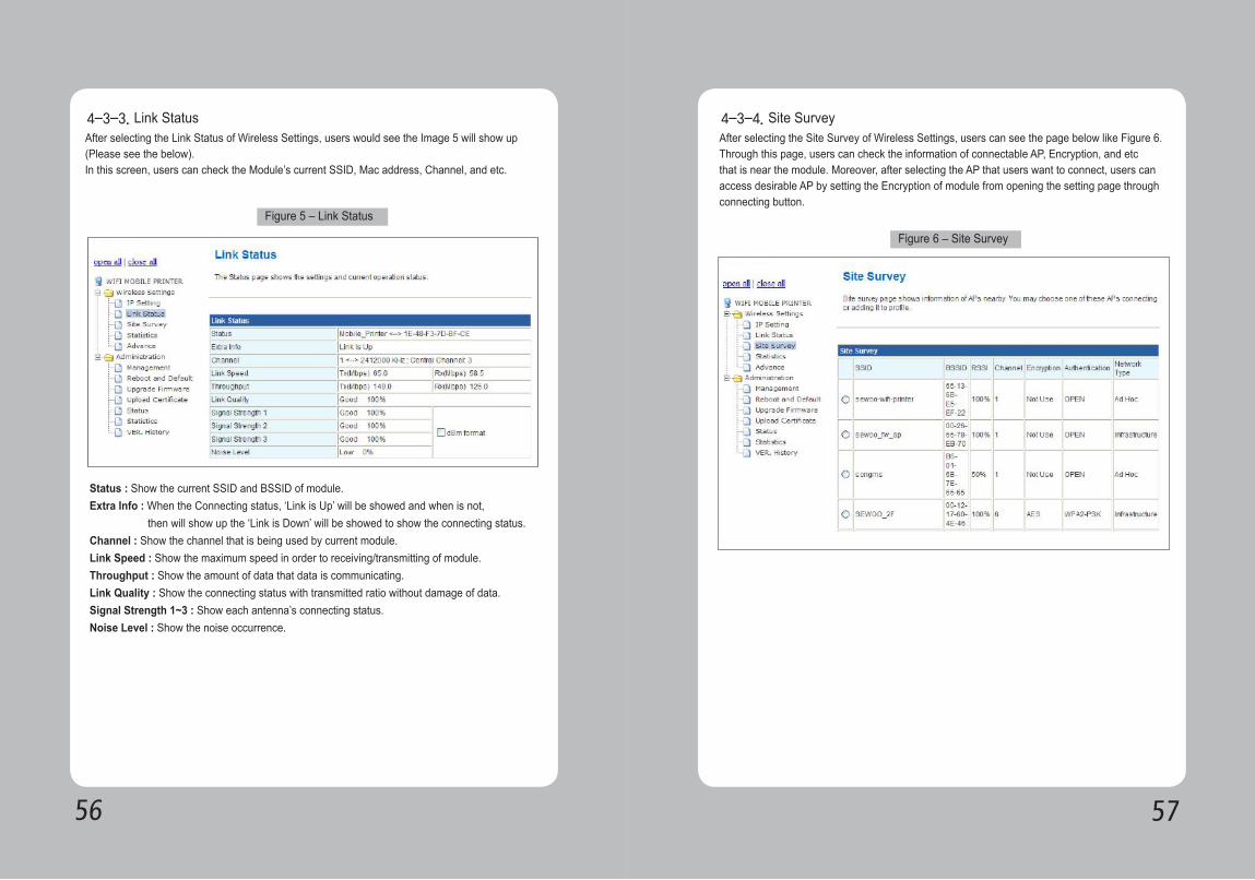
After selecting the Link Status of Wireless Settings, users would see the Image 5 will show up (Please see the below). In this screen, users can check the Module’s current SSID, Mac address, Channel, and etc.
4-3-3. Link Status
Figure 5 – Link Status
Status : Show the current SSID and BSSID of module. Extra Info : When the Connecting status, ‘Link is Up’ will be showed and when is not, then will show up the ‘Link is Down’ will be showed to show the connecting status. Channel : Show the channel that is being used by current module. Link Speed : Show the maximum speed in order to receiving/transmitting of module. Throughput : Show the amount of data that data is communicating. Link Quality : Show the connecting status with transmitted ratio without damage of data. Signal Strength 1~3 : Show each antenna’s connecting status.Noise Level : Show the noise occurrence.
After selecting the Site Survey of Wireless Settings, users can see the page below like Figure 6. Through this page, users can check the information of connectable AP, Encryption, and etc that is near the module. Moreover, after selecting the AP that users want to connect, users can access desirable AP by setting the Encryption of module from opening the setting page through connecting button.
4-3-4. Site Survey
Figure 6 – Site Survey
5958
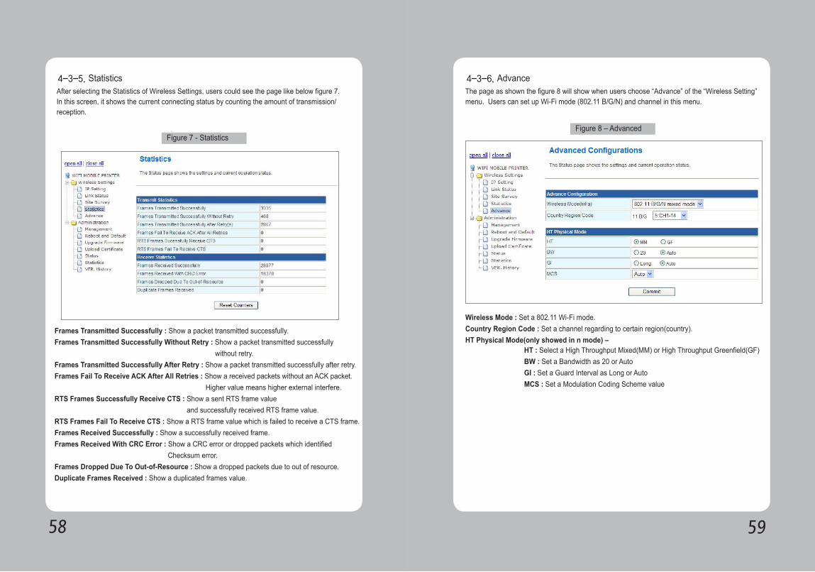
After selecting the Statistics of Wireless Settings, users could see the page like below figure 7. In this screen, it shows the current connecting status by counting the amount of transmission/reception.
4-3-5. Statistics
Figure 7 - Statistics
Frames Transmitted Successfully : Show a packet transmitted successfully.Frames Transmitted Successfully Without Retry : Show a packet transmitted successfully without retry.Frames Transmitted Successfully After Retry : Show a packet transmitted successfully after retry.Frames Fail To Receive ACK After All Retries : Show a received packets without an ACK packet. Higher value means higher external interfere.RTS Frames Successfully Receive CTS : Show a sent RTS frame value and successfully received RTS frame value.RTS Frames Fail To Receive CTS : Show a RTS frame value which is failed to receive a CTS frame.Frames Received Successfully : Show a successfully received frame.Frames Received With CRC Error : Show a CRC error or dropped packets which identified Checksum error.Frames Dropped Due To Out-of-Resource : Show a dropped packets due to out of resource.Duplicate Frames Received : Show a duplicated frames value.
The page as shown the figure 8 will show when users choose “Advance” of the “Wireless Setting” menu. Users can set up Wi-Fi mode (802.11 B/G/N) and channel in this menu.
4-3-6. Advance
Figure 8 – Advanced
Wireless Mode : Set a 802.11 Wi-Fi mode.Country Region Code : Set a channel regarding to certain region(country).HT Physical Mode(only showed in n mode) –
HT : Select a High Throughput Mixed(MM) or High Throughput Greenfield(GF)BW : Set a Bandwidth as 20 or AutoGI : Set a Guard Interval as Long or AutoMCS : Set a Modulation Coding Scheme value
6160
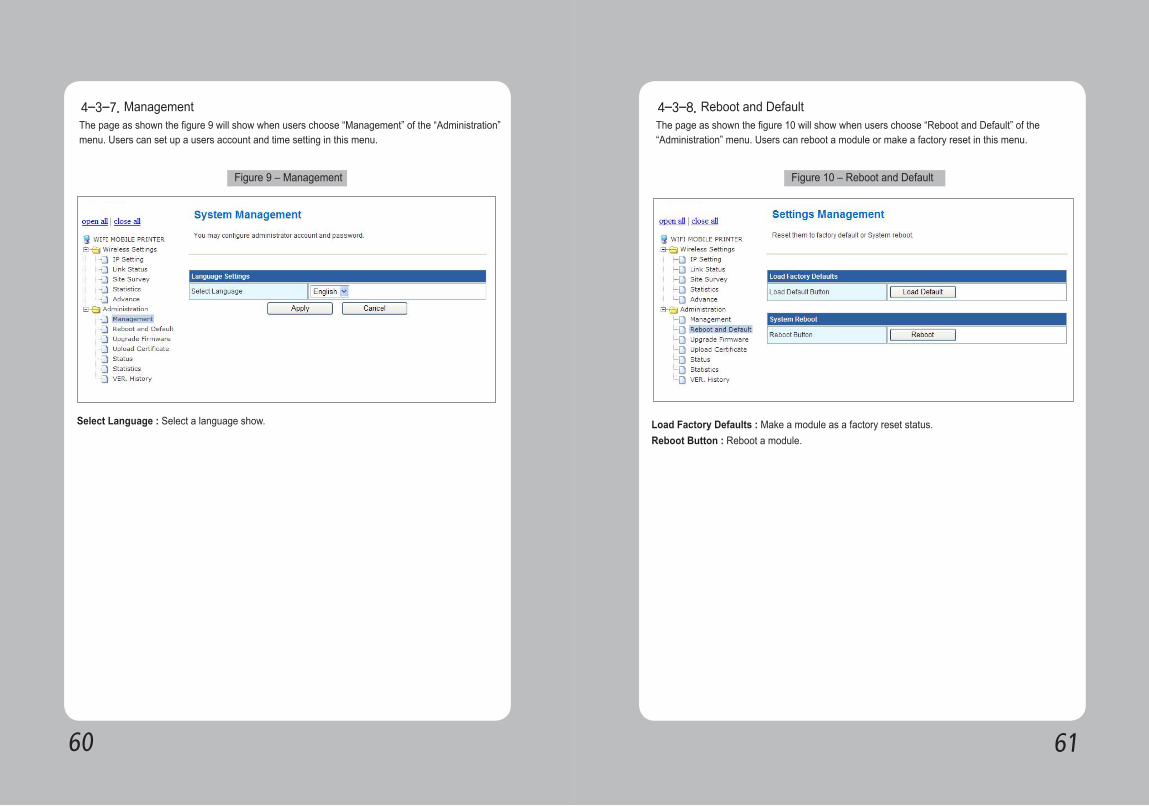
The page as shown the figure 9 will show when users choose “Management” of the “Administration” menu. Users can set up a users account and time setting in this menu.
4-3-7. Management
Figure 9 – Management
Select Language : Select a language show.
The page as shown the figure 10 will show when users choose “Reboot and Default” of the “Administration” menu. Users can reboot a module or make a factory reset in this menu.
4-3-8. Reboot and Default
Figure 10 – Reboot and Default
Load Factory Defaults : Make a module as a factory reset status.Reboot Button : Reboot a module.
6362
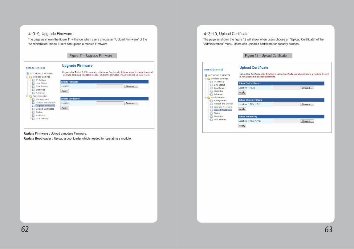
The page as shown the figure 11 will show when users choose an “Upload Firmware” of the “Administration” menu. Users can upload a module Firmware.
4-3-9. Upgrade Firmware
Figure 11 – Upgrade Firmware
Update Firmware : Upload a module Firmware.Update Boot loader : Upload a boot loader which needed for operating a module.
The page as shown the figure 12 will show when users choose an “Upload Certificate” of the “Administration” menu. Users can upload a certificate for security protocol.
4-3-10. Upload Certificate
Figure 12 – Upload Certificate
6564
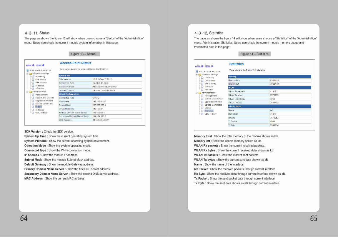
The page as shown the figure 13 will show when users choose a “Status” of the “Administration” menu. Users can check the current module system information in this page.
4-3-11. Status
Figure 13 – Status
SDK Version : Check the SDK version.System Up Time : Show the current operating system time.System Platform : Show the current operating system environment.Operation Mode : Show the system operating mode.Connected Type : Show the Wi-Fi connection mode.IP Address : Show the module IP address.Subnet Mask : Show the module Subnet Mask address.Default Gateway : Show the module Gateway address.Primary Domain Name Server : Show the first DNS server address.Secondary Domain Name Server : Show the second DNS server address.MAC Address : Show the current MAC address.
The page as shown the figure 14 will show when users choose a “Statistics” of the “Administration” menu. Administration Statistics. Users can check the current module memory usage and transmitted data in this page.
4-3-12. Statistics
Figure 14 – Statistics
Memory total : Show the total memory of the module shown as kB.Memory left : Show the usable memory shown as kB.WLAN Rx packets : Show the current received packets.WLAN Rx bytes : Show the current received data shown as kB.WLAN Tx packets : Show the current sent packets.WLAN Tx bytes : Show the current sent data shown as kB.Name : Show the name of the interface.Rx Packet : Show the received packets through current interface.Rx Byte : Show the received data through current interface shown as kB.Tx Packet : Show the sent packet data through current interface.Tx Byte : Show the sent data shown as kB through current interface.
6766
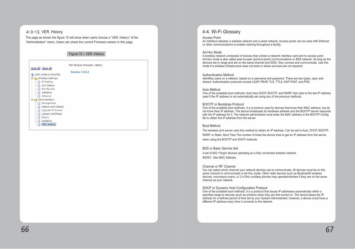
The page as shown the figure 15 will show when users choose a “VER. History” of the “Administration” menu. Users can check the current Firmware version in this page.
4-3-13. VER. History
Figure 15 – VER. History
4-4. Wi-Fi Glossary Access Point An interface between a wireless network and a wired network. Access points can be used with Ethernet or other communications to enable roaming throughout a facility.
Ad-Hoc Mode A wireless network composed of devices that contain a network interface card and no access point. Ad-Hoc mode is also called peer-to-peer (point-to-point) communications or BSS network. As long as the devices are in range and are on the same channel and SSID, they connect and communicate. Use this mode if a wireless infrastructure does not exist or where services are not required.
Authentication Method Identifies users on a network, based on a username and password. There are two types, open and shared. Authentication protocols include LEAP, PEAP, TLS, TTLS, EAP-FAST, and PSK.
Auto Method One of the available boot methods. Auto tries DHCP, BOOTP, and RARP, then sets to the last IP address used if the IP address is not automatically set using any of the previous methods.
BOOTP or Bootstrap Protocol One of the available boot methods. It is a protocol used by devices that know their MAC address, but do not know their IP address. The device broadcasts its hardware address and the BOOTP server responds with the IP address for it. The network administrator must enter the MAC address in the BOOTP Config file to obtain the IP address from the server.
Boot Method The wireless print server uses this method to obtain an IP address. Can be set to Auto, DHCP, BOOTP, RARP, or Static. Boot Tries The number of times the device tries to get an IP address from the server when using the BOOTP and DHCP methods.
BSS or Basic Service Set A set of 802.11b/g/n devices operating as a fully connected wireless network. BSSID : See MAC Address.
Channel or RF ChannelYou can select which channel your network devices use to communicate. All devices must be on the same channel to communicate in Ad-Hoc mode. Other radio devices such as Bluetooth® wireless devices, microwave ovens, or 2.4-GHz cordless phones may operate/interfere if they are on the same channel as your network.
DHCP or Dynamic Host Configuration Protocol One of the available boot methods. It is a protocol that issues IP addresses automatically within a specified range to devices (such as printers) when they are first turned on. The device keeps the IP address for a defined period of time set by your System Administrator; however, a device could have a different IP address every time it connects to the network.
6968
EAP (Extensible Authentication Protocol) Defines how to pass authentication information between the device and authentication server. The authentication is handled by the EAP type: FAST, TLS, TTLS, etc.
FAST (Flexible Authentication via Secure Tunneling) Cisco Systems® developed this authentication protocol. It does not use certificates to authenticate, but a PAC (Protected Access Credential), which is managed dynamically by the server. The PAC is distributed one at a time to the client manually or automatically.
Gateway Allows connections (communications) between different subnets on a network.
Infrastructure Mode Requires an access point to communicate with other devices on the network. In infrastructure mode, wireless devices can communicate with each other or with a wired network.
IP AddressOne of the available boot methods. It is a protocol used by devices that know their MAC address, but do An Internet Protocol identifier for a device on a network. It consists of four 3-digit numeric fields, separated by periods. Each number can be zero to 255. An IP address has two components, the network address and the host address. Most company networks have ranges for their IP addresses.
Boot Method The wireless print server uses this method to obtain an IP address. Can be set to Auto, DHCP, BOOTP, RARP, or Static. Boot Tries The number of times the device tries to get an IP address from the server when using the BOOTP and DHCP methods.
LEAP (Lightweight Extensible Authentication Protocol) Cisco Systems® introduced this authentication protocol and provides mutual authentication with unique WEP keys for each user. New keys are issued based on a time limit. Changing the WEP key time limits provides additional security.
LPD/LPR A printer protocol that uses TCP/IP to establish connections between printers on a network. Also known as Line Printer Daemon/Line Printer Remote.
MAC Address or Media Access Control A hardware address (6-byte) that uniquely identifies each node of a network.The MAC address is set during manufacturing and does not change. Also, two Network Interface Cards (NIC) will not have the same value.
MSCHAPv2 The Microsoft® version of CHAP. It is a three-way handshake protocol that is more secure than PAP. It provides mutual authentication between devices.
NIC or Network Interface Card An adapter (board or card) that can be inserted into a device, so the device can be connected to a network. The NIC converts data from the device into the form transmitted or received from the network.
NodeA processing location on a network. The location can be a workstation, computer, or printer. Each Node has a unique MAC address.
Open Authentication This allows any device to authenticate and then attempt to communicate with the access point. Any wireless device can authenticate with the accesspoint, but if WEP is used, the device can communicate only if its WEP keys match the access point’s. There is no challenge that occurs, you either have the correct key or not when you communicate with the access point. By eliminating the challenge process, it actually makes this more secure than shared key authentication
PAP (Password Authentication Protocol) A simple authentication protocol used with PPP (Point-to-Point Protocol). It is a plain text password system, which is not very secure. Pathname/The location of a particular file or directory that includes the full path to the needed filename or directory. This is a combination of path and filename.
PEAP (Protected Extensible Authentication Protocol) : Authenticates clients into a network using only server-side certificates, which makes implementing and administering a wireless LAN easier.
PingA way to determine if a device is accessible. It sends a packet to the specified address and waits for a reply.
Protocol This is the way two devices transmit data between each other, including error checking, data compression, and how messages start and end.
PSK (Pre-Shared Key) Authentication mode of WPA used in SOHO environments. The key value(or pass-phrase) is used for network authentication only (not data encryption). It does not use a RADIUS server like the other modes, but uses a shared key to provide the initial authentication with the access point or host.
RADIUS (Remote Authentication Dial-In Server)This is an authentication server, such as the Cisco® ACS, Microsoft® IAS, etc.
RARPOne of the available boot methods. The device sends an RARP request and the RARP server responds with an IP address. The device knows its MAC address and the server responds with the IP address for it.
7170
RouterAny device that forwards data along networks. Routers are located at gateways.
Shared Authentication The access point sends an unencrypted challenge text string to any device attempting to communicate with it. The device requesting authentication encrypts the challenge text and sends it back to the access point. If the challenge text is encrypted correctly, the access point allows the requesting device to authenticate. Both the unencrypted challenge and the encrypted challenge can be monitored; however, this leaves the access point open to attack. Because of this weakness, shared key authentication can be less secure than open authentication.
Signal Strength A percentage (1 to 100) of the connection between the device and access point. If the signal strength is 0, there is no connection with the access point; 30 or less indicates you may be experiencing interference or close to being out of access point range, and below 50, printing performance could be affected. To improve the signal strength, try moving the printer closer to the access point and away from other radio devices such as Bluetooth® wireless devices, microwave ovens, or 2.4-GHz cordless phones.
Speed or Transmit Rate Sets the maximum rate of communication between the devices on thenetwork. It is also called transmit rate.
SSID or Service Set Identifier A unique identifier that must match for all nodes on a subnetwork to communicate with each other. It consists of up to 32 characters (any printable character, including spaces). If using the space character, it must be enclosed in quotation marks. It is case-sensitive.
Static Method One of the available boot methods. Use static if your network uses fixed configuration. The IP address remains the same every time the device connects to the network.
Subnet A portion of a network that shares a common address component. On TCP/IP networks, subnets are all devices with the same prefix. For example, all devices that start with 192.192.192 are part of the same subnet. Dividing a network into subnets is useful for both security and performance reasons.
Subnet Mask A mask is used to determine what subnet an IP address belongs to. Companies oftenhave ranges of IP addresses that can be described by one or more masks. For example, a mask of 255.255.255.0 allows variation in the last position only, because the first three positions are fixed.
TCP/IPA way that two devices can transmit data between each other. TCP/IP(Transmission Control Protocol/ Internet Protocol) is generally the standard for transmitting data over a network.
TKIP (Temporal Key Integrity Protocol)Changes the encryption keys regularly and has time limits before new keys are created. Changing the key periodically provides additional security.
TLS (Transport Layer Security) A cryptographic protocol that uses client-side and server-side certificates to authenticate users on the Web. It can dynamically create user-based and session-based keys.
TTLS (Tunneled Transport Layer Security) Provides certificate-based, server-side, mutual authentication of the client and network through an encrypted channel (or tunnel). It can dynamically create user-based and session-based keys.
WEP or Wired Equivalent Privacy A security protocol for wireless local area networks. WEP was designed to provide the same level of security as that of a wired network, which is inherently more secure than a wireless network because wired networks are easily protected against unauthorized access. Wireless networks use radio waves to communicate and can be vulnerable to unauthorized users. WEP provides security by encrypting data over radio waves so that it is protected as it is transmitted. However, it has been found that WEP is not as secure as once believed
128 Bit / 64 Bit WEP Key This is the 64 or 128 bit WEP key that must match other Nodes’ encryption keys to communicate: 10 hex characters for 64 bit (40 serspecifiedcharacters), or 26 hex characters for 128 bit (104 user-specified characters). You must use the same key values for devices to communicate with each other
WLAN or Wireless Local Area Network A LAN that uses high-frequency radio waves to communicate between nodes, rather than telephone wires, etc
WPA (Wi-Fi Protected Access)A network security protocol that uses improved authentication and temporal keys. It was created to address the weaknesses of WEP encryption.
WPA2(or IEEE 802.11i) : A network security protocol with stronger encryption than WPA. It was created to address the weaknesses of WEP encryption.
NOTEIf one part of a wireless network has WEP enabled, they all must have it enabled with the same key or they cannot communicate.
7372
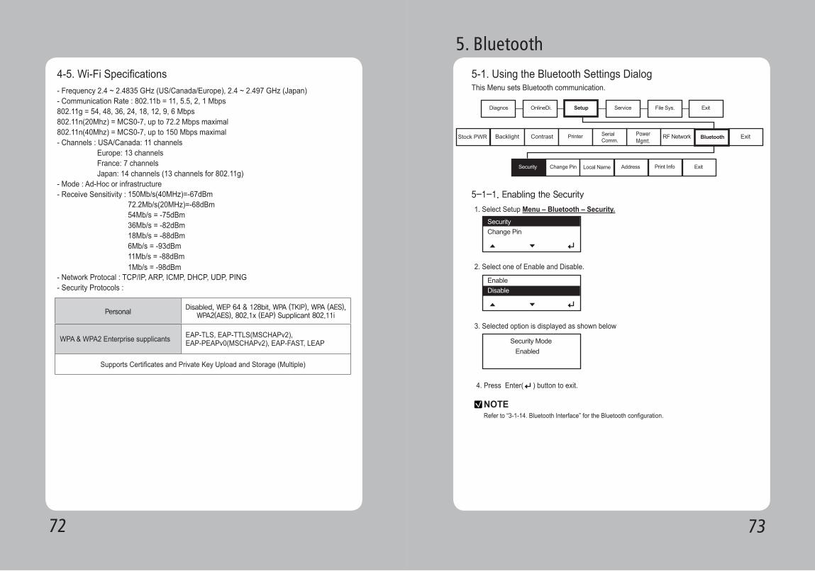
4-5. Wi-Fi Specifications - Frequency 2.4 ~ 2.4835 GHz (US/Canada/Europe), 2.4 ~ 2.497 GHz (Japan)- Communication Rate : 802.11b = 11, 5.5, 2, 1 Mbps802.11g = 54, 48, 36, 24, 18, 12, 9, 6 Mbps802.11n(20Mhz) = MCS0-7, up to 72.2 Mbps maximal 802.11n(40Mhz) = MCS0-7, up to 150 Mbps maximal- Channels : USA/Canada: 11 channels Europe: 13 channels France: 7 channels Japan: 14 channels (13 channels for 802.11g)- Mode : Ad-Hoc or infrastructure- Receive Sensitivity :
- Network Protocal : TCP/IP, ARP, ICMP, DHCP, UDP, PING- Security Protocols :
150Mb/s(40MHz)=-67dBm72.2Mb/s(20MHz)=-68dBm54Mb/s = -75dBm 36Mb/s = -82dBm 18Mb/s = -88dBm 6Mb/s = -93dBm 11Mb/s = -88dBm 1Mb/s = -98dBm
Personal
Disabled, WEP 64 & 128bit, WPA (TKIP), WPA (AES), WPA2(AES), 802.1x (EAP) Supplicant 802.11i
WPA & WPA2 Enterprise supplicants EAP-TLS, EAP-TTLS(MSCHAPv2),EAP-PEAPv0(MSCHAPv2), EAP-FAST, LEAP
Supports Certificates and Private Key Upload and Storage (Multiple)
5-1. Using the Bluetooth Settings Dialog
5. Bluetooth
This Menu sets Bluetooth communication.
1. Select Setup Menu – Bluetooth – Security.
2. Select one of Enable and Disable.
3. Selected option is displayed as shown below
4. Press Enter( ) button to exit.
5-1-1. Enabling the Security
NOTERefer to “3-1-14. Bluetooth Interface” for the Bluetooth configuration.
7574
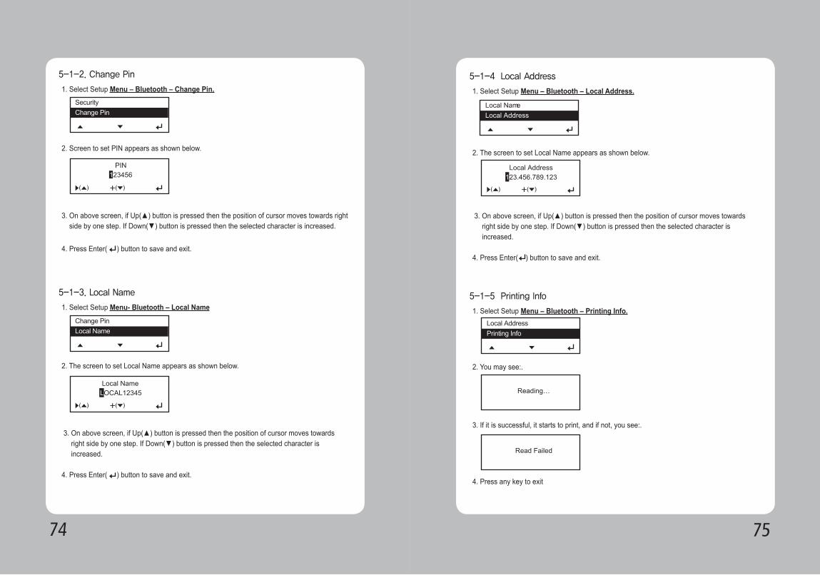
1. Select Setup Menu – Bluetooth – Change Pin.
1. Select Setup Menu- Bluetooth – Local Name
2. The screen to set Local Name appears as shown below.
2. Screen to set PIN appears as shown below.
3. On above screen, if Up(▲) button is pressed then the position of cursor moves towards right side by one step. If Down(▼) button is pressed then the selected character is increased.
3. On above screen, if Up(▲) button is pressed then the position of cursor moves towards right side by one step. If Down(▼) button is pressed then the selected character is increased.
4. Press Enter( ) button to save and exit.
4. Press Enter( ) button to save and exit.
5-1-2. Change Pin
5-1-3. Local Name
1. Select Setup Menu – Bluetooth – Local Address.
1. Select Setup Menu – Bluetooth – Printing Info.
2. You may see:.
3. If it is successful, it starts to print, and if not, you see:.
4. Press any key to exit
2. The screen to set Local Name appears as shown below.
3. On above screen, if Up(▲) button is pressed then the position of cursor moves towards right side by one step. If Down(▼) button is pressed then the selected character is increased.
4. Press Enter( ) button to save and exit.
5-1-4 Local Address
5-1-5 Printing Info
Local AddressLocal Name
7776
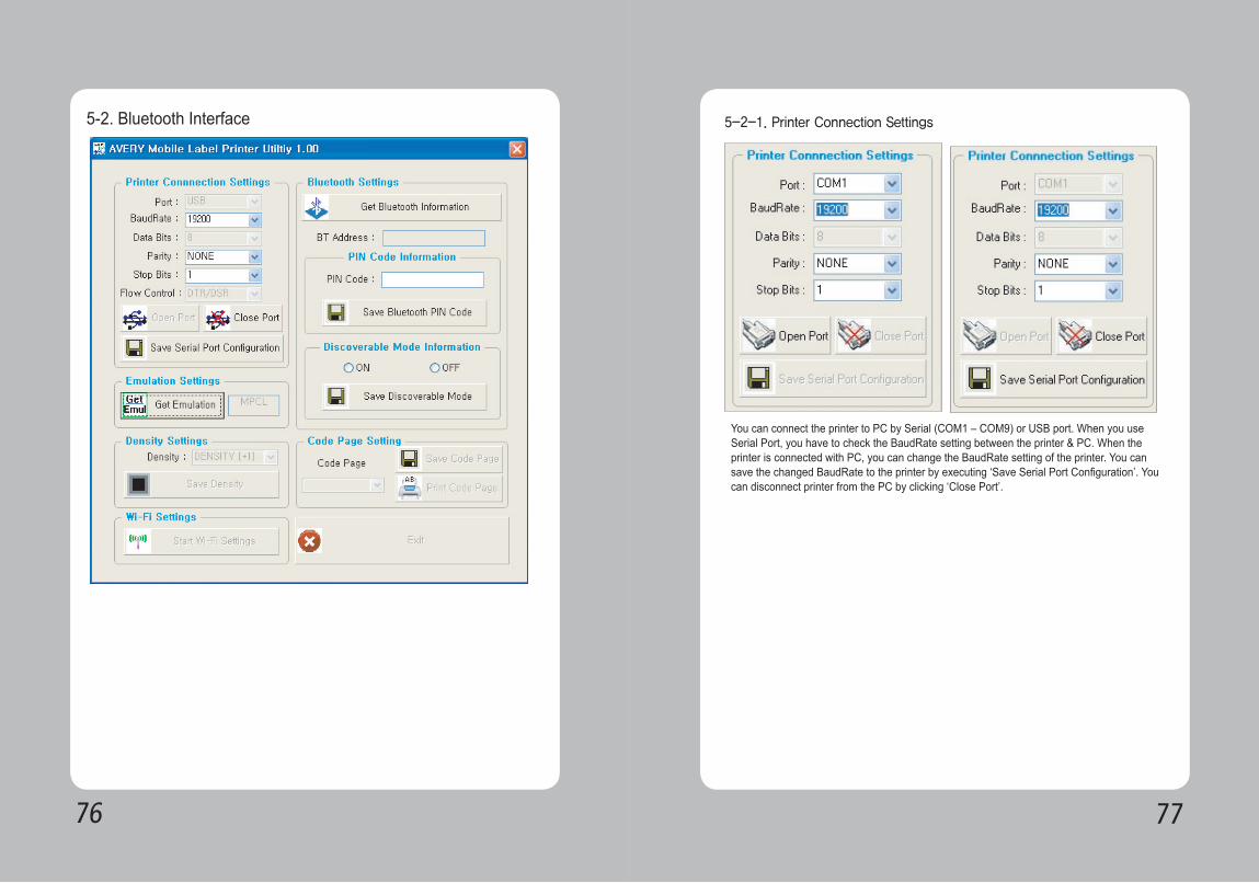
5-2. Bluetooth Interface 5-2-1. Printer Connection Settings
You can connect the printer to PC by Serial (COM1 – COM9) or USB port. When you use Serial Port, you have to check the BaudRate setting between the printer & PC. When the printer is connected with PC, you can change the BaudRate setting of the printer. You can save the changed BaudRate to the printer by executing ‘Save Serial Port Configuration’. You can disconnect printer from the PC by clicking ‘Close Port’.
7978
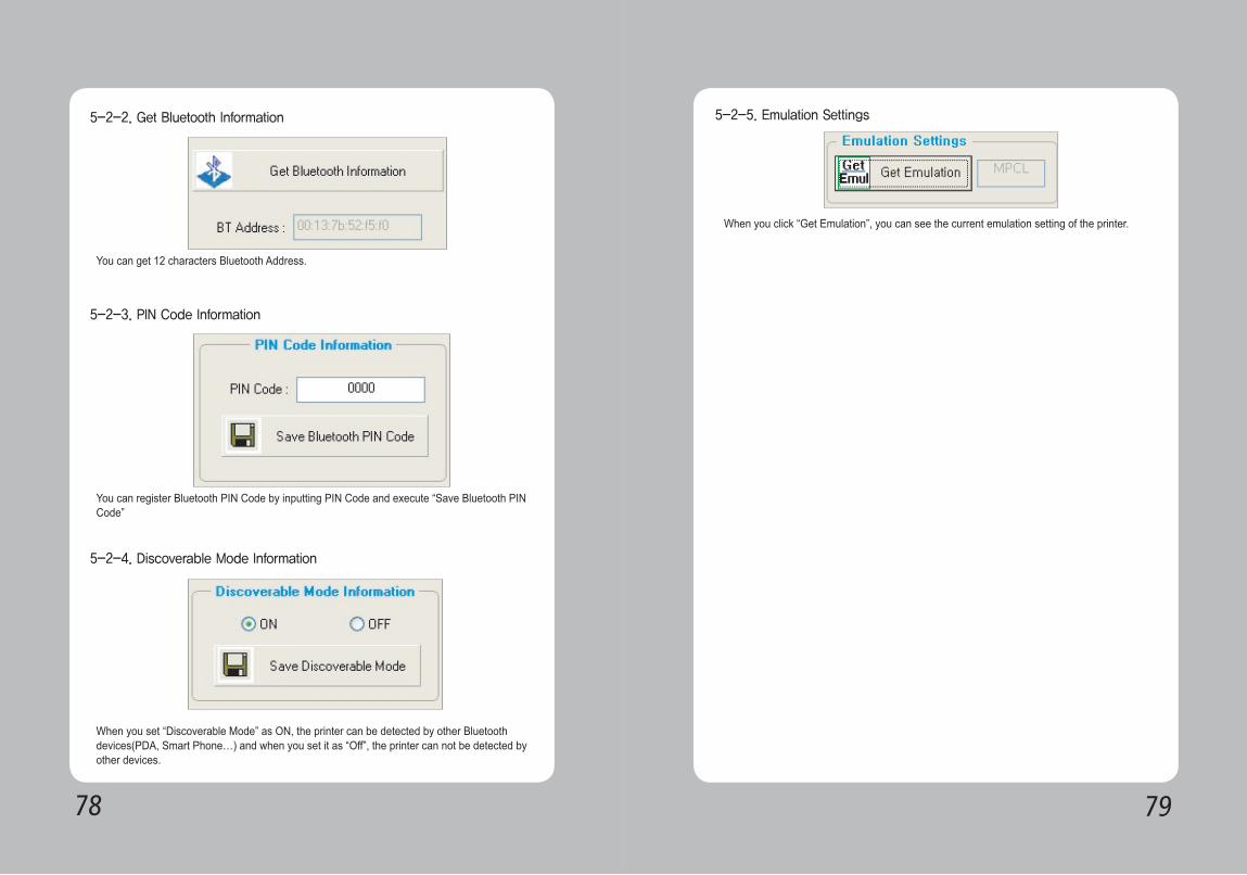
5-2-2. Get Bluetooth Information
5-2-3. PIN Code Information
5-2-4. Discoverable Mode Information
You can get 12 characters Bluetooth Address.
You can register Bluetooth PIN Code by inputting PIN Code and execute “Save Bluetooth PIN Code”
When you set “Discoverable Mode” as ON, the printer can be detected by other Bluetooth devices(PDA, Smart Phone…) and when you set it as “Off”, the printer can not be detected by other devices.
5-2-5. Emulation Settings
When you click “Get Emulation”, you can see the current emulation setting of the printer.