model to assess energy consumption in industrial lumber · pdf filemodel to assess energy...
TRANSCRIPT

Maderas. Ciencia y tecnología 11(1): 33-46, 2009
33
ISSN 0717-3644ISSN online 0718-221X
MODEL TO ASSESS ENERGY CONSUMPTION IN INDUSTRIAL LUMBER KILNS
Diego Miguel Elustondo1, Luiz Oliveira1
ABSTRACT
In this work, a kiln energy model was developed with the main objective of assessing energy con-sumption in industrial lumber kilns. The model simulates kiln energy consumption on the basis of a simplifi ed description of kiln technologies, energy systems and lumber characteristics, and it requires a minimum set of empirical parameters that are calibrated in practice. In this study, the model calibration was performed for a laboratory scale conventional kiln and three experimental drying runs of 50 mm thick spruce-pine lumber. The results of this study illustrate how the kiln energy model is calibrated, compares experimental and simulated MC, energy and water consumption, and describes how the model simulates different components of energy consumption that can be used to evaluate potential energy saving strategies.
Keywords: Conventional kiln, lumber drying, mathematical model, energy effi ciency, heat losses.
INTRODUCTION
A conventional kiln is relatively simple to operate and maintain, and it is a cost-effective technology for wood drying. The downside of this technology is energy effi ciency. A conventional kiln consumes around 50% more energy than that required to evaporate the water. Energy consumption in a conven-tional kiln is required for moisture evaporation, heating the kiln and lumber, kiln ventilation, thermal losses, air leakage, and air humidifi cation. Kiln maintenance could reduce air leakage and reduce the humidifi cation requirements, but the benefi ts in terms of energy savings are usually small. Higher reduction in energy consumption can be achieved by dehumidifi er units, vent heat exchangers, and air drying, but these strategies usually require considerably modifi cations to an existing commercial process. To assess the economic viability of potential energy saving strategies, a computer model was developed and tested to estimate energy consumption in industrial kilns.
Kiln energy consumption has been measured and simulated by several authors (Breiner et al. 1984, Davis 1954, Esping 1982, Elustondo and Oliveira 2006, Elustondo and Oliveira 2007, Fortin et al. 2004, Hopper and Toennisson 1980, Kininmonth et al. 1980, Kudra 2004, Laytner and Arganbright 1984, Menshutina et al. 2004, Mujumdar 1995, Simpson and Tschernitz 1980, Simpson 1991, Taylor 1979, Taylor 1982, Salin 2004, Shottafer and Shuler 1974), and there numerous well known measures that can be taken to reduce kiln energy consumption (such as the use of direct-fi red energy systems, installation of heat exchangers in kiln vents, partial air drying of green lumber, lumber preheating with kiln exhaust air, optimization of drying schedules, reduction of air fl ow velocity, lumber sorting before drying, and season planning). Depending on the case, only one or two of these strategies may be prac-tical for a particular drying operation. Therefore, the model developed in this study is a practical tool to assess industrial drying operations and determine the energy saving strategy that generates the best return of the implementation cost.
1 FPInnovations – Forintek. Vancouver, British Columbia. V6T 1W5, CanadaCorresponding author: [email protected]: 31.10. 2008 Accepted: 22.12 2008.

Maderas. Ciencia y tecnología 11(1): 33-46, 2009
34
Universidad del Bío - Bío
KILN ENERGY MODEL
Conventional temperature kilns use hot air at controlled velocity, temperature and relative humidity to evaporate moisture from the lumber. Figure 1 depicts the basic components of conventional kiln drying. Inside the kiln, lumber is arranged in layers that are separated by narrow strips (usually 20 mm) to allow the fl ow of air between layers. As the air fl ows between the lumber layers, the dry-bulb tempe-rature reduces (unless the wood is hotter than the air), and the wet-bulb temperature remains the same (unless there is condensation over the lumber surfaces). Energy for drying is supplied by an energy system, and the moisture evaporated from the lumber is released outside the kiln through a ventilation system. Conventional kilns commonly also include a humidifi cation system to compensate for humidi-ty losses due to uncontrolled air leakage.
Figure 1: Basic components of kiln lumber drying
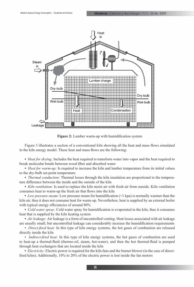
Figure 2 shows a diagram of a kiln during humidifi cation (using low pressure steam). The fi gure refers to the case of lumber warm-up, in which a certain amount of condensation occurs in order to avoid premature uncontrolled drying. As it is shown in the diagram, condensation corresponds to the situation in which dry-bulb temperature corresponds to the wet-bulb temperature.
Maderas. Ciencia y tecnología 11(1): 33-46, 2009
35
Model to Assess Energy Consumption...: Elustondo and Oliveira.
Figure 2: Lumber warm-up with humidifi cation system
Figure 3 illustrates a section of a conventional kiln showing all the heat and mass fl ows simulated in the kiln energy model. These heat and mass fl ows are the following:
• Heat for drying: Includes the heat required to transform water into vapor and the heat required to break molecular bonds between wood fi ber and absorbed water
• Heat for warm-up: Is required to increase the kiln and lumber temperature from its initial values to the dry-bulb set-point temperature
• Thermal conduction: Thermal losses through the kiln insulation are proportional to the tempera-ture difference between the inside and the outside of the kiln
• Kiln ventilation: Is used to replace the kiln moist air with fresh air from outside. Kiln ventilation consumes heat to warm-up the fresh air that fl ows into the kiln
• Low pressure steam: Low pressure steam for humidifi cation (<1 kpa) is normally warmer than the kiln air, thus it does not consume heat for warm-up. Nevertheless, heat is supplied by an external boiler with typical energy effi ciencies of around 80%
• Cold water spray: Cold water spray for humidifi cation is evaporated in the kiln, thus it consumes heat that is supplied by the kiln heating system
• Air leakage: Air leakage is a form of uncontrolled venting. Heat losses associated with air leakage are usually small, but uncontrolled leakage can considerably increase the humidifi cation requirements
• Direct-fi red heat: In this type of kiln energy systems, the hot gases of combustion are released directly inside the kiln
• Indirect-fi red heat: In this type of kiln energy systems, the hot gases of combustion are used to heat-up a thermal-fl uid (thermo-oil, steam, hot-water), and then the hot thermal-fl uid is pumped through heat exchangers that are located inside the kiln
• Electricity: Electric power is required for the kiln fans and the burner blower (in the case of direct-fi red kilns). Additionally, 10% to 20% of the electric power is lost inside the fan motors

Maderas. Ciencia y tecnología 11(1): 33-46, 2009
36
Universidad del Bío - Bío
Figure 3: General diagram showing all components of the kiln energy model
The kiln energy model combines two types of energy systems and two types of humidifi cation sys-tems within a single unit operation. This provides the capability to simulate most of the conventional kilns that are typically found in industry. The mathematical solution is obtained by solving the simulta-neous the heat and mass balances with well know thermodynamics equations. The detailed implemen-tation of these equations is rather complicated because of the large number of components involved, thus the details concerning the mathematical implementation are not included in this paper. This paper only describes the simplifi ed equations that were used to solve the heat and mass balances in a way that is suitable for kiln energy assessment by commercial operators.
Airfl ow heat balance
The mass fl ow (m) and enthalpy (h) balances concerning the heat transferred from the air to the lumber (Q) are calculated between the inlet and the outlet sides of the lumber load. For simplicity, it is assumed that the airfl ow between the lumber layers only contains pure air (a), vapor due to the air humidity (v), and vapor produced by moisture evaporation (vap):
(1)
(2)

Maderas. Ciencia y tecnología 11(1): 33-46, 2009
37
Model to Assess Energy Consumption...: Elustondo and Oliveira.
Heat transferred from the airfl ow to the lumber is divided into the sensible heat absorbed by the lumber (QL) and the enthalpy (h) difference between the produced vapor (vap) and the moisture (mc) evaporated from the lumber:
(3)
Then, by combining these three equations, the heat balance is re-written on the basis of the average properties between entry and exit sides of the lumber load:
(4)
Where:
= Average heat of evaporation
= Average vapor fl ow between the lumber layers
For simplifi cation, enthalpy differences are calculated on the basis of heat capacities (Cp) and tem-perature drop across the load (∆T
DB). Mass fl ow are calculated on the basis of density (ρ), air velocity
(v) and total area (A) available for the airfl ow. The relative volume of air and vapor in the airfl ow are calculated on the basis of total pressure (P) and vapor partial pressure (Pv). Finally, lumber (L) sensible heat is calculated on the basis of density, heat capacity, and the time (t) derivative of the average lumber temperature (T):
(5)
Drying rate (mvap
), lumber temperature (TL) and temperature drop across the load (∆T
DB) are unk-
nown variables of the process, and they need to be simulated by the model. For the purpose of industrial kiln assessment, these three parameters are estimated on the basis of the following simplifi ed models:
Drying rateAn accurate drying rate simulation requires a comprehensive description of the drying process
(lumber dimensions, dry-bulb temperature, wet-bulb temperature, and air velocity) and wood physical properties (heat capacity, basic density, thermal conductivity, gas permeability, diffusion coeffi cient, and capillarity). In this model however, a simplifi ed approach was proposed to estimate drying rate with an empirical equation that is calibrated with experimental kiln data. The required experimental data is the total drying time, and lumber initial and fi nal moisture content.
In the simplifi ed approach, it is assumed that lumber drying is controlled by moisture diffusion. This means that lumber drying rate is calculated as a diffusion coeffi cient (D
eff) multiplied by the difference
between actual moisture content (MC) and equilibrium moisture content (EMC). Theoretically, the diffusion control model is only valid for MC below fi ber saturation point (FSP), but it was found in
Maderas. Ciencia y tecnología 11(1): 33-46, 2009
38
Universidad del Bío - Bío
practice that after calibration, the diffusion control model can be applied to the entire drying process. For this application, the diffusion control model is calibrated using the following empirical MC*, EMC* and FSP* parameters:
• EMC* = The apparent EMC that results from assuming that the experimental drying rate under diffusion control reduces approximately linearly with the reduction of MC
• FSP* = The apparent FSP that correspond to the MC at which the experimental drying rate starts reducing approximately linearly with the reduction of MC
• MC* = The effective MC that is equal to the actual lumber MC for drying below FSP*, and equal to FSP* for drying above FSP*
By using these parameters, the simplifi ed drying rate model results in the following equation:
(6)
The relationship between Deff
and temperature is obtained from literature (Siau 1995). Literature indicates that D
eff is equal to a constant (D
0) multiplied by an exponential function of the energy of ac-
tivation (∆H=34150 kJ/kmol), the ideal gas constant (R=8.314 kJ/kmol.K), and the absolute (Kelvin) temperature (T):
(7)
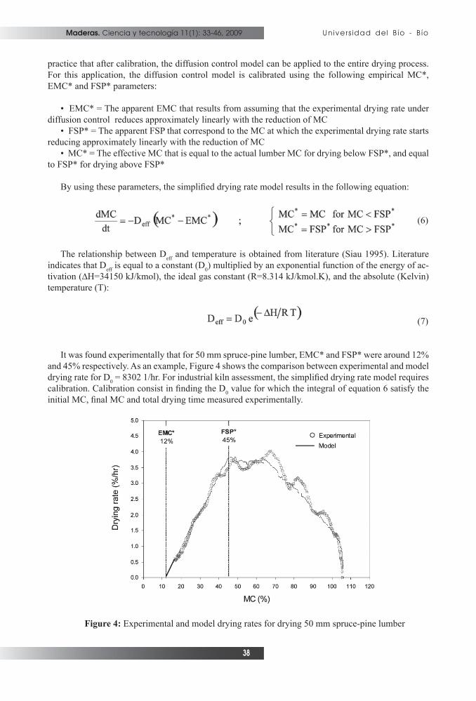
It was found experimentally that for 50 mm spruce-pine lumber, EMC* and FSP* were around 12% and 45% respectively. As an example, Figure 4 shows the comparison between experimental and model drying rate for D
0 = 8302 1/hr. For industrial kiln assessment, the simplifi ed drying rate model requires
calibration. Calibration consist in fi nding the D0 value for which the integral of equation 6 satisfy the
initial MC, fi nal MC and total drying time measured experimentally.
Figure 4: Experimental and model drying rates for drying 50 mm spruce-pine lumber
Maderas. Ciencia y tecnología 11(1): 33-46, 2009
39
Model to Assess Energy Consumption...: Elustondo and Oliveira.
Lumber temperatureTo estimate lumber temperature it is assumed that moisture evaporation occurs only at the lumber
surfaces. During warm-up, lumber surface temperature is assumed to be equal to the wet-bulb. During drying, lumber surface temperature is assumed to be equal to the dry-bulb. Then, heat fl ow into the lumber is calculated as one-dimensional thermal conduction in the direction (l) of the lumber thickness. The lumber thermal conductivity (k
L) is obtained from literature (Siau 1995), and the model also con-
siders the possibility of ice concentration (cice
) inside the lumber:
(8)
Where the ice heat of melting (∆hice
) is approximately 334.4 kJ/kg (Siau 1995). In theory, free-water freezes below 0°C, but because of the various soluble substances inside the wood, wood freezing oc-curs gradually between 0°C and -15°C (Skaar 1972, Sparks et al. 2000). Therefore, the model assumes that the percentage of frozen free-water inside the wood increases proportionally to the reduction of temperature between 0°C and -15°C.
Vapor condensationDuring warm-up, the temperature drop across the load (∆T
DB) calculated with equation 5 may be
larger than the difference between dry-bulb and wet-bulb temperatures at the entry side of the load. This means that vapor condenses over the lumber surfaces, and dry-bulb and wet-bulb (T
WB) tempera-
tures are equal at the exit side of the load. Under this conditions, the drying rate (mvap
) model described in equation 6 is replaced by a vapor condensation model based on the partial vapor pressure (Pv) deri-vative and the wet-bulb drop across the load (∆T
WB):
(9)
During condensation, wet-bulb temperature is equal to the dew-point, thus the partial vapor pres-sure derivative can be estimated with the thermodynamic relationship known as Clapeyron equation (Incropera and Witt, 1996):
(10)
Where the water molecular weight is Mw=18.015 kg/kmol. Then, by taking into account that dry-
bulb and wet-bulb temperatures are equal at the exit side of the load, the temperature drop across the load is determined by simple arithmetic:
(11)
Kiln ParametersThere are three heat and mass fl ows in the model affected by the kiln structure, namely, thermal
conduction through the kiln walls, heat for warming-up the kiln, and air leakage through defective kiln sealing. For the purposes of this model, these fl ows are calculated using three calibration parameters, namely, the kiln heat transfer coeffi cient (H
K), the kiln heat capacity (Cp
K) and the total air leakage
(ALK). These calibration parameters are overall properties accounting for the entire kiln structure, and

Maderas. Ciencia y tecnología 11(1): 33-46, 2009
40
Universidad del Bío - Bío
they are determined experimentally for each particular kiln.
Thermal conduction through the kiln insulation (Qthermal
) is calculated on the basis of the kiln heat transfer coeffi cient (H
K) and the difference between the dry-bulb temperature and the temperature out-
side the kiln (T0):
(12)
Where AK is the kiln total area including walls, roof, fl oor, metallic frame and concrete basis. Heat to warm-up the kiln structure (Q
Cp) is calculated on the basis of the kiln heat capacity (Cp
K) and the time
(t) derivative of the dry-bulb. Since most of the kiln mass is concentrated in the walls, roof and fl oor, the kiln heat capacity is also referred to the kiln total area:
(13)
Air leakage (ALK) accounts for all the fresh air that fl ows into the kiln through openings other than
the kiln vents. Contrary to common perception, air leakage in this model is not the warm moist air fl owing out of the kiln (that can be easily seen in practice because it becomes foggy when the weather is cold), but the fresh air fl owing into the kiln which then requires heating. Warm air fl owing out of the kiln contains air leakage, moisture evaporated from the lumber, steam supplied by the humidifi cation system, and products of gas combustion in the case of direct-fi re kilns.
MATERIALS AND METHODS
The model was implemented in Microsoft-Excel and validated with three experimental drying runs of 50 mm spruce-pine lumber. Each drying run comprised 136 pieces arranged in a single pack of 17 boards across and 8 layers high (an approximately 2.8 m3 pack). Drying runs were performed in a 3.1 m long pilot scale electrically heated kiln with capacity for approximately 11 m3 of lumber (assuming 50 mm nominal lumber thickness and 20 mm stickers). The experimental pilot scale kiln was equipped with electric heaters and a cold water spray, and the kiln wall is comprised of commercial 4” aluminum fi berglass insulated panels. For each experiment, the following experimental data was collected:
• Air velocity at ambient temperature with a hot-wire anemometer• Two 25 mm samples from each green board to determine initial MC by the oven-dry method• Total energy consumption was recorded from a electric power use meter• Total water consumption (cold water spray) measured with a water fl ow meter• Total lumber weight before, during and after drying measured with in-kiln load cells• Dry-bulb and wet-bulb temperatures measured and recorded with in-kiln temperature sensors• MC during drying was calculated by the kiln controller on the basis of lumber weight and initial MC
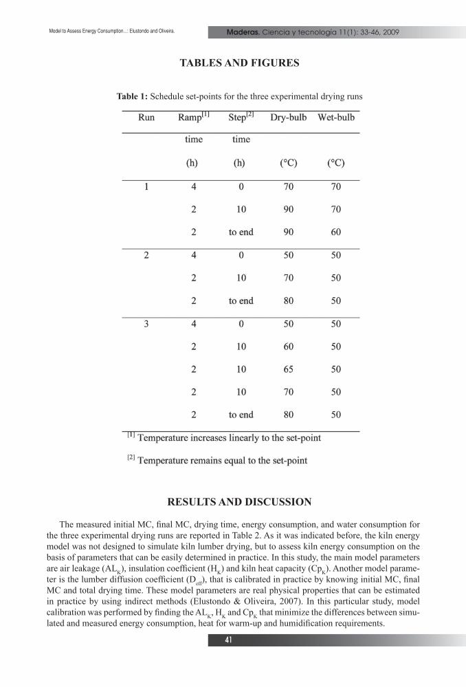
Each drying run had markedly different initial MC so they were dried using different schedules. The set-point temperature values for the three experimental drying runs are reported in Table 1. The kiln controller was designed to record all control actions in a computer fi le. After the experiments, the kiln controller information was used to calculate fan power, heaters power and water volume rate at any time during the drying process.
Maderas. Ciencia y tecnología 11(1): 33-46, 2009
41
Model to Assess Energy Consumption...: Elustondo and Oliveira.
TABLES AND FIGURES
Table 1: Schedule set-points for the three experimental drying runs
RESULTS AND DISCUSSION
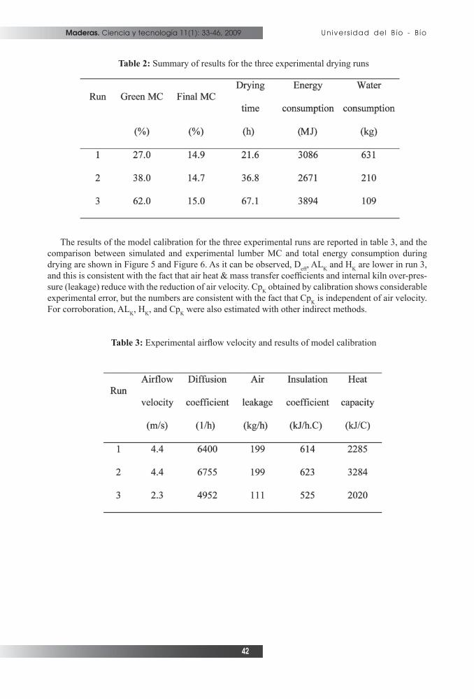
The measured initial MC, fi nal MC, drying time, energy consumption, and water consumption for the three experimental drying runs are reported in Table 2. As it was indicated before, the kiln energy model was not designed to simulate kiln lumber drying, but to assess kiln energy consumption on the basis of parameters that can be easily determined in practice. In this study, the main model parameters are air leakage (AL
K), insulation coeffi cient (H
K) and kiln heat capacity (Cp
K). Another model parame-
ter is the lumber diffusion coeffi cient (Deff
), that is calibrated in practice by knowing initial MC, fi nal MC and total drying time. These model parameters are real physical properties that can be estimated in practice by using indirect methods (Elustondo & Oliveira, 2007). In this particular study, model calibration was performed by fi nding the AL
K, H
K and Cp
K that minimize the differences between simu-
lated and measured energy consumption, heat for warm-up and humidifi cation requirements.
Maderas. Ciencia y tecnología 11(1): 33-46, 2009
42
Universidad del Bío - Bío
Table 2: Summary of results for the three experimental drying runs
The results of the model calibration for the three experimental runs are reported in table 3, and the comparison between simulated and experimental lumber MC and total energy consumption during drying are shown in Figure 5 and Figure 6. As it can be observed, D
eff, AL
K and H
K are lower in run 3,
and this is consistent with the fact that air heat & mass transfer coeffi cients and internal kiln over-pres-sure (leakage) reduce with the reduction of air velocity. Cp
K obtained by calibration shows considerable
experimental error, but the numbers are consistent with the fact that CpK is independent of air velocity.
For corroboration, ALK, H
K, and Cp
K were also estimated with other indirect methods.
Table 3: Experimental airfl ow velocity and results of model calibration

Maderas. Ciencia y tecnología 11(1): 33-46, 2009
43
Model to Assess Energy Consumption...: Elustondo and Oliveira.
Figure 5: Comparison between simulated and experimental moisture content curves
Figure 6: Comparison between simulated and experimental energy consumption curves
HK was estimated on the basis of the kiln geometry and average thermal conductivities measured
Maderas. Ciencia y tecnología 11(1): 33-46, 2009
44
Universidad del Bío - Bío
at FPInnovations (1.12 W/m2.C for the aluminum fi berglass panels, and 2.01 W/m2.C for the concrete fl oor). Cp
K and AL
K were determined through basic heat and mass balances performed for the empty
kiln. First, the kiln was warmed-up at constant heat power until the dry-bulb temperature reached the equilibrium point (around 90°C). At equilibrium, the heat power supplied to the kiln is equal to the heat losses, thus a generic heat transfer coeffi cient (including both thermal insulation and air leakage) was calculated with a defi nition similar to equation 11. Then, warm-up heat is equal to the total energy supplied to the kiln minus the integral of the heat losses. After that, the humidifi cation system (cold water spray) was turned on until both dry-bulb and wet-bulb temperatures reached equilibrium again. At equilibrium, total water supplied to the kiln was equal to the vapor lost due to air leakage, and AL
K
was calculated with a mass balance.
The parameters estimated through indirect methods were ALK ≈ 50~150 kg/h, H
K ≈ 450 kJ/h.C, and
CpK ≈ 2000 kJ/C. Because the lumber changes the airfl ow distribution inside the kiln, the air leakage
and heat transfer coeffi cient measured for the empty kiln are not technically equal to the parameters calibrated for the kiln with lumber. Nevertheless, the measured and the calibrated parameters are in the same order of magnitude, thus confi rming that the model parameters are equivalent to real physical properties of the kiln.
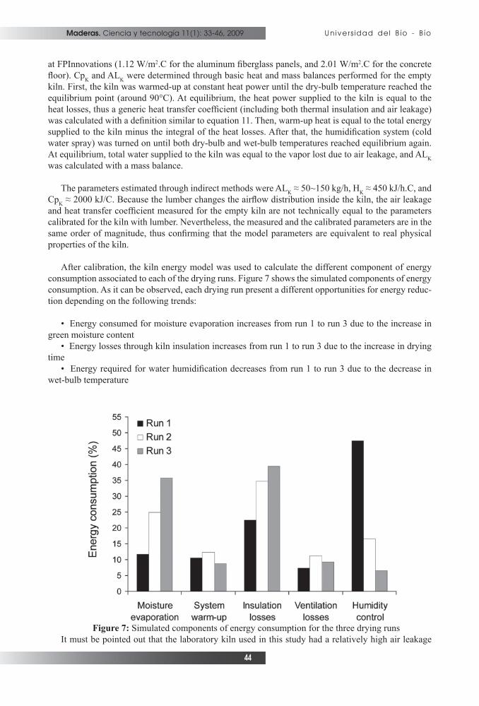
After calibration, the kiln energy model was used to calculate the different component of energy consumption associated to each of the drying runs. Figure 7 shows the simulated components of energy consumption. As it can be observed, each drying run present a different opportunities for energy reduc-tion depending on the following trends:
• Energy consumed for moisture evaporation increases from run 1 to run 3 due to the increase in green moisture content
• Energy losses through kiln insulation increases from run 1 to run 3 due to the increase in drying time
• Energy required for water humidifi cation decreases from run 1 to run 3 due to the decrease in wet-bulb temperature
Figure 7: Simulated components of energy consumption for the three drying runsIt must be pointed out that the laboratory kiln used in this study had a relatively high air leakage

Maderas. Ciencia y tecnología 11(1): 33-46, 2009
45
Model to Assess Energy Consumption...: Elustondo and Oliveira.
in comparison with the volume of dried lumber. Since air leakage increases air humidity losses, Run 1 (using high wet-bulb temperature) consumed considerably more energy for humidifi cation than Runs 2 and 3.
CONCLUSIONS
A kiln energy model was developed with the main objective of assessing energy consumption in industrial lumber kilns. The model estimates kiln energy consumption on the basis of a simplifi ed des-cription of kiln technologies, energy systems and lumber characteristics, and it requires a minimum set of empirical parameters that are calibrated in practice. These kiln parameters are air leakage, insulation coeffi cient and kiln heat capacity. Additionally, the model includes a parameter to estimate lumber drying rate, that is calibrated with experimental data of drying time and lumber initial and fi nal MC.
The model is designed to perform kiln energy assessments and subsequent analysis of potential energy saving strategies. In this study, the kiln assessment consisted in measuring initial MC, fi nal MC, drying time, and total energy and water consumption for a laboratory scale conventional kiln. After measuring these data, the model was calibrated by adjusting the parameters until the simulated drying time, fi nal MC and total energy and water consumption were equal to the experimental values. In an industrial kiln assessment, the determination of the kiln parameters could be different depending on the equipment and information that is available at the site.
The parameters obtained from model calibration were validated by comparing with the air leakage, insulation coeffi cient and kiln heat capacity measured through other indirect methods. This confi rmed that the model parameters are equivalent to real physical properties of the kiln. After calibration, the model was used to simulate lumber MC, total energy and water consumption, kiln energy effi ciency, and energy losses due to thermal conduction, ventilation, humidifi cation and warm-up. In an industrial kiln assessment, simulated kiln energy effi ciency and energy losses will be use determine the need of kiln maintenance and the economic viability of implementing potential energy saving strategies.
REFERENCES
Breiner, T.A.; Arganbright, D.G.; Huber, D. 1984. On-line Monitoring of Heat and Energy Con-sumption. In Proceedings of the North American Wood Drying Symposium, Mississippi, USA.
Davis, V.C. 1954. Steam Consumption in the Kiln Drying of Western Softwoods. Forest Products Journal 4(5): 258-260.
Elustondo, D.M.; Oliveira, L. 2006. Opportunities to Reduce Energy Consumption in Softwood Lumber Drying. Drying Technology 24: 653-662.
Elustondo, D.M; and Oliveira, L. 2007. Strategies to Reduce Energy Consumption in Kiln Drying. In Proceedings of the 10th International IUFRO Conference, Maine, USA.
Esping, B. 1982. Energy Saving in Timber Drying. Wood Technology Report No. 12. Svenska Träforskningsinstitutet, Stockholm.
Fortin, Y.; Defo, M.; Nabhani, M.; Tremblay, C.; Gendron, G. 2004. A simulation tool for the optimization of lumber drying schedules. Drying Technology 22(5): 963-983.
Hopper, D.L.; Toennisson, R.L. 1980. Reducing energy consumption and related costs at the saw-
Maderas. Ciencia y tecnología 11(1): 33-46, 2009
46
Universidad del Bío - Bío
mill and dry kiln. In Proceedings of Sawmill Maintenance Workshop, Nashville, Tennessee.
Incropera, F.P.; Witt, D.P. 1996. Fundamentals of heat and mass transfer. John Wiley & Sons, New York, 4th edition.
Kininmonth, J.A.; Miller, W.; Riley, S. 1980. Energy Consumption in Lumber Drying. In Procee-dings of the IUFRO Conference, Division V, Oxford, England.
Kudra, T. 2004. Energy aspects in drying. Drying Technology 22 (5), 917-932.
Laytner, F.Y.; Arganbright, D.G. 1984. Within Kiln Variability in Transmission Heat Losses. Forest Products Journal 34(2): 62-68.
Menshutina, N.V.; Gordienko, M.G.; Voynovskiy, A.A.; Kudra, T. 2004. Dynamic Analysis of Drying Energy Consumption. Drying Technology 22 (10): 2281-2290.
Mujumdar, A.S. 1995. Handbook of Industrial Drying. Marcel Dekker, Inc., New York, 2nd edi-tion.
Salin, J.G. 2004. Determination of the most economical drying schedule and air velocity in soft-wood drying. In Proceeding of COST Action E15: Advances in Drying of Wood, Athens, Greece.
Shottafer, J.E.; Shuler, C.E. 1974. Estimating heat consumption in kiln drying lumber. Life Scien-
ces and Agriculture Experiment Station, Technical Bulletin 73.
Siau, J.F. 1995. Infl uence of Moisture on Physical Properties. Virginia Polytechnic Institute and State University, New York, USA.
Simpson, W.T.; Tschernitz, J.L. 1980. Time, costs, and energy consumption for drying red oak lumber as affected by thickness and thickness variation. Forest Products Journal 30(1): 23–27.
Simpson, W.T. 1991. Dry Kiln Operator’s Manual. U.S. Department of Agriculture Handbook AH-188, Madison, USA.
Skaar, C. 1972. Water in Wood. Syracuse University Press, Syracuse, USA.
Sparks, J.P.; Campbel, G.S.; Black, R.A. 2000. Liquid Water Content of Wood Tissue at Tempe-ratures Below 0°C. Canadian Journal of Forestry Research 30: 624-630.
Taylor, F.W. 1979. Energy Consumption of Southern Pine Kilns. Southern Lumberman 215(2680):, 85-88.
Taylor, F.W. 1982. A comparison of energy requirements for kiln drying southern pine at different drying temperatures. Wood and Fibre Sciences 14 (4): 246-253.