model cfc clearfire condensing boiler - cleaverbrooks.com · 1 rev. 05-2012 table of contents model...
TRANSCRIPT
Model CFC ClearFire Condensing Boiler
Table of Contents
MODEL CFC FEATURES AND BENEFITS . . . . . . . . . . . . . . . . . . . . . . . . . . . . . . . . . . . . . . . . . . . . . . . . . . . . . . . . . . . . . . . . .3MODEL CFC PRODUCT OFFERING . . . . . . . . . . . . . . . . . . . . . . . . . . . . . . . . . . . . . . . . . . . . . . . . . . . . . . . . . . . . . . . . . . . . .5DIMENSIONS AND RATINGS . . . . . . . . . . . . . . . . . . . . . . . . . . . . . . . . . . . . . . . . . . . . . . . . . . . . . . . . . . . . . . . . . . . . . . . . . .8PERFORMANCE DATA . . . . . . . . . . . . . . . . . . . . . . . . . . . . . . . . . . . . . . . . . . . . . . . . . . . . . . . . . . . . . . . . . . . . . . . . . . . . . .8ENGINEERING DATA . . . . . . . . . . . . . . . . . . . . . . . . . . . . . . . . . . . . . . . . . . . . . . . . . . . . . . . . . . . . . . . . . . . . . . . . . . . . . . .20STACK/BREECHING SIZE CRITERIA . . . . . . . . . . . . . . . . . . . . . . . . . . . . . . . . . . . . . . . . . . . . . . . . . . . . . . . . . . . . . . . . . . . . .55CB FALCON CONTROLLER . . . . . . . . . . . . . . . . . . . . . . . . . . . . . . . . . . . . . . . . . . . . . . . . . . . . . . . . . . . . . . . . . . . . . . . . . . .67
List of FiguresAluFer Inserts . . . . . . . . . . . . . . . . . . . . . . . . . . . . . . . . . . . . . . . . . . . . . . . . . . . . . . . . . . . . . . . . . . . . . . . . . . . . . . . . . . . . . . . . . . . . . . . . . . . . . .3Fireside Access . . . . . . . . . . . . . . . . . . . . . . . . . . . . . . . . . . . . . . . . . . . . . . . . . . . . . . . . . . . . . . . . . . . . . . . . . . . . . . . . . . . . . . . . . . . . . . . . . . . . .3Premix Burner Technology . . . . . . . . . . . . . . . . . . . . . . . . . . . . . . . . . . . . . . . . . . . . . . . . . . . . . . . . . . . . . . . . . . . . . . . . . . . . . . . . . . . . . . . . . . . .4Model CFC Heat Flow and Component Orientation . . . . . . . . . . . . . . . . . . . . . . . . . . . . . . . . . . . . . . . . . . . . . . . . . . . . . . . . . . . . . . . . . . . . . . . . .5ClearFire Control Panel . . . . . . . . . . . . . . . . . . . . . . . . . . . . . . . . . . . . . . . . . . . . . . . . . . . . . . . . . . . . . . . . . . . . . . . . . . . . . . . . . . . . . . . . . . . . . . .7Model CFC Dimensional Views . . . . . . . . . . . . . . . . . . . . . . . . . . . . . . . . . . . . . . . . . . . . . . . . . . . . . . . . . . . . . . . . . . . . . . . . . . . . . . . . . . . . . . . .9Competitive Condensation Analysis . . . . . . . . . . . . . . . . . . . . . . . . . . . . . . . . . . . . . . . . . . . . . . . . . . . . . . . . . . . . . . . . . . . . . . . . . . . . . . . . . . . . .14Emissions Data Clearfire . . . . . . . . . . . . . . . . . . . . . . . . . . . . . . . . . . . . . . . . . . . . . . . . . . . . . . . . . . . . . . . . . . . . . . . . . . . . . . . . . . . . . . . . . . . . . .16-19Pressure Drop Curves . . . . . . . . . . . . . . . . . . . . . . . . . . . . . . . . . . . . . . . . . . . . . . . . . . . . . . . . . . . . . . . . . . . . . . . . . . . . . . . . . . . . . . . . . . . . . . . .22-25Condensate Piping Direct To Drain . . . . . . . . . . . . . . . . . . . . . . . . . . . . . . . . . . . . . . . . . . . . . . . . . . . . . . . . . . . . . . . . . . . . . . . . . . . . . . . . . . . . .30Optional Condensate Treatment Assembly . . . . . . . . . . . . . . . . . . . . . . . . . . . . . . . . . . . . . . . . . . . . . . . . . . . . . . . . . . . . . . . . . . . . . . . . . . . . . . . .31Condensate Piping for Multiple Boilers . . . . . . . . . . . . . . . . . . . . . . . . . . . . . . . . . . . . . . . . . . . . . . . . . . . . . . . . . . . . . . . . . . . . . . . . . . . . . . . . . .31Condensate Treatment Tank for Multiple Boilers . . . . . . . . . . . . . . . . . . . . . . . . . . . . . . . . . . . . . . . . . . . . . . . . . . . . . . . . . . . . . . . . . . . . . . . . . . .32Gas Piping Schematic . . . . . . . . . . . . . . . . . . . . . . . . . . . . . . . . . . . . . . . . . . . . . . . . . . . . . . . . . . . . . . . . . . . . . . . . . . . . . . . . . . . . . . . . . . . . . . . .33Gas Header Piping . . . . . . . . . . . . . . . . . . . . . . . . . . . . . . . . . . . . . . . . . . . . . . . . . . . . . . . . . . . . . . . . . . . . . . . . . . . . . . . . . . . . . . . . . . . . . . . . . . .34Model CFC Minimum Room Clearance Dimensions . . . . . . . . . . . . . . . . . . . . . . . . . . . . . . . . . . . . . . . . . . . . . . . . . . . . . . . . . . . . . . . . . . . . . . . .36CFC Seismic Mounting . . . . . . . . . . . . . . . . . . . . . . . . . . . . . . . . . . . . . . . . . . . . . . . . . . . . . . . . . . . . . . . . . . . . . . . . . . . . . . . . . . . . . . . . . . . . . . .36No Primary Loop with Domestic Water and 2-Way Divert Valve . . . . . . . . . . . . . . . . . . . . . . . . . . . . . . . . . . . . . . . . . . . . . . . . . . . . . . . . . . . . . .38Two Boilers and Three Variable Temperature Zones (No Primary Loop) . . . . . . . . . . . . . . . . . . . . . . . . . . . . . . . . . . . . . . . . . . . . . . . . . . . . . . . .39Two-Pipe Primary/Secondary Piping with Domestic Hot Water . . . . . . . . . . . . . . . . . . . . . . . . . . . . . . . . . . . . . . . . . . . . . . . . . . . . . . . . . . . . . . .40Two-Pipe Primary/Secondary Piping . . . . . . . . . . . . . . . . . . . . . . . . . . . . . . . . . . . . . . . . . . . . . . . . . . . . . . . . . . . . . . . . . . . . . . . . . . . . . . . . . . . .41No Primary Loop . . . . . . . . . . . . . . . . . . . . . . . . . . . . . . . . . . . . . . . . . . . . . . . . . . . . . . . . . . . . . . . . . . . . . . . . . . . . . . . . . . . . . . . . . . . . . . . . . . . .42Domestic Water Heating, No Primary Loop . . . . . . . . . . . . . . . . . . . . . . . . . . . . . . . . . . . . . . . . . . . . . . . . . . . . . . . . . . . . . . . . . . . . . . . . . . . . . . .43Domestic Water with On/Off and 3-Way Valves . . . . . . . . . . . . . . . . . . . . . . . . . . . . . . . . . . . . . . . . . . . . . . . . . . . . . . . . . . . . . . . . . . . . . . . . . . .44Piping ‘Hybrid’ Boilers . . . . . . . . . . . . . . . . . . . . . . . . . . . . . . . . . . . . . . . . . . . . . . . . . . . . . . . . . . . . . . . . . . . . . . . . . . . . . . . . . . . . . . . . . . . . . . .45‘Hybrid’ Boilers with Domestic Water . . . . . . . . . . . . . . . . . . . . . . . . . . . . . . . . . . . . . . . . . . . . . . . . . . . . . . . . . . . . . . . . . . . . . . . . . . . . . . . . . . .462 Pipe System, Typical (reverse-return) . . . . . . . . . . . . . . . . . . . . . . . . . . . . . . . . . . . . . . . . . . . . . . . . . . . . . . . . . . . . . . . . . . . . . . . . . . . . . . . . . .47
1 Rev. 05-2012

Model CFC ClearFire Commercial Boilers
Zoning with Zone Valves . . . . . . . . . . . . . . . . . . . . . . . . . . . . . . . . . . . . . . . . . . . . . . . . . . . . . . . . . . . . . . . . . . . . . . . . . . . . . . . . . . . . . . . . . . . . .48Domestic Water with 2 Boilers and 2 Coils . . . . . . . . . . . . . . . . . . . . . . . . . . . . . . . . . . . . . . . . . . . . . . . . . . . . . . . . . . . . . . . . . . . . . . . . . . . . . . .49Two Opening Outside Wall Method . . . . . . . . . . . . . . . . . . . . . . . . . . . . . . . . . . . . . . . . . . . . . . . . . . . . . . . . . . . . . . . . . . . . . . . . . . . . . . . . . . . . .51Two Opening Ducted Method . . . . . . . . . . . . . . . . . . . . . . . . . . . . . . . . . . . . . . . . . . . . . . . . . . . . . . . . . . . . . . . . . . . . . . . . . . . . . . . . . . . . . . . . . .52One Opening Method . . . . . . . . . . . . . . . . . . . . . . . . . . . . . . . . . . . . . . . . . . . . . . . . . . . . . . . . . . . . . . . . . . . . . . . . . . . . . . . . . . . . . . . . . . . . . . . .53Two Opening Engineered Method . . . . . . . . . . . . . . . . . . . . . . . . . . . . . . . . . . . . . . . . . . . . . . . . . . . . . . . . . . . . . . . . . . . . . . . . . . . . . . . . . . . . . .54Optional Direct Vent Combustion Kit . . . . . . . . . . . . . . . . . . . . . . . . . . . . . . . . . . . . . . . . . . . . . . . . . . . . . . . . . . . . . . . . . . . . . . . . . . . . . . . . . . .55Horizontal through the wall venting using inside air for combustion . . . . . . . . . . . . . . . . . . . . . . . . . . . . . . . . . . . . . . . . . . . . . . . . . . . . . . . . . . . .58Horizontal flue through-wall with direct vent combustion intake . . . . . . . . . . . . . . . . . . . . . . . . . . . . . . . . . . . . . . . . . . . . . . . . . . . . . . . . . . . . . .59Inside Air - Vertical Vent . . . . . . . . . . . . . . . . . . . . . . . . . . . . . . . . . . . . . . . . . . . . . . . . . . . . . . . . . . . . . . . . . . . . . . . . . . . . . . . . . . . . . . . . . . . . .62Vertical Stack with Direct Vent Combustion Air . . . . . . . . . . . . . . . . . . . . . . . . . . . . . . . . . . . . . . . . . . . . . . . . . . . . . . . . . . . . . . . . . . . . . . . . . . .63Electrical Connections CFC 500-2500 . . . . . . . . . . . . . . . . . . . . . . . . . . . . . . . . . . . . . . . . . . . . . . . . . . . . . . . . . . . . . . . . . . . . . . . . . . . . . . . . . . .64Electrical Connections CFC 3300 . . . . . . . . . . . . . . . . . . . . . . . . . . . . . . . . . . . . . . . . . . . . . . . . . . . . . . . . . . . . . . . . . . . . . . . . . . . . . . . . . . . . . . .65CFC Rear Connections . . . . . . . . . . . . . . . . . . . . . . . . . . . . . . . . . . . . . . . . . . . . . . . . . . . . . . . . . . . . . . . . . . . . . . . . . . . . . . . . . . . . . . . . . . . . . . .66CB Falcon pinout . . . . . . . . . . . . . . . . . . . . . . . . . . . . . . . . . . . . . . . . . . . . . . . . . . . . . . . . . . . . . . . . . . . . . . . . . . . . . . . . . . . . . . . . . . . . . . . . . . .69
List of TablesU.S. Standard Dimensions Model CFC Boiler . . . . . . . . . . . . . . . . . . . . . . . . . . . . . . . . . . . . . . . . . . . . . . . . . . . . . . . . . . . . . . . . . . . . . . . . . . . . .10Metric Dimensions Model CFC Boiler . . . . . . . . . . . . . . . . . . . . . . . . . . . . . . . . . . . . . . . . . . . . . . . . . . . . . . . . . . . . . . . . . . . . . . . . . . . . . . . . . . .11Model CFC Boiler Ratings (Sea Level to 2000 Feet) . . . . . . . . . . . . . . . . . . . . . . . . . . . . . . . . . . . . . . . . . . . . . . . . . . . . . . . . . . . . . . . . . . . . . . . .12Altitude Correction for Input Capacity at Various Altitude Levels . . . . . . . . . . . . . . . . . . . . . . . . . . . . . . . . . . . . . . . . . . . . . . . . . . . . . . . . . . . . .13ClearFire Efficiency . . . . . . . . . . . . . . . . . . . . . . . . . . . . . . . . . . . . . . . . . . . . . . . . . . . . . . . . . . . . . . . . . . . . . . . . . . . . . . . . . . . . . . . . . . . . . . . . .14 - 15Noise Level . . . . . . . . . . . . . . . . . . . . . . . . . . . . . . . . . . . . . . . . . . . . . . . . . . . . . . . . . . . . . . . . . . . . . . . . . . . . . . . . . . . . . . . . . . . . . . . . . . . . . . . .20CFC Flow Rates . . . . . . . . . . . . . . . . . . . . . . . . . . . . . . . . . . . . . . . . . . . . . . . . . . . . . . . . . . . . . . . . . . . . . . . . . . . . . . . . . . . . . . . . . . . . . . . . . . . .21CFC Flow Rates (Metric) . . . . . . . . . . . . . . . . . . . . . . . . . . . . . . . . . . . . . . . . . . . . . . . . . . . . . . . . . . . . . . . . . . . . . . . . . . . . . . . . . . . . . . . . . . . . .22Model CFC Minimum Over Pressure Requirements . . . . . . . . . . . . . . . . . . . . . . . . . . . . . . . . . . . . . . . . . . . . . . . . . . . . . . . . . . . . . . . . . . . . . . . .26Model CFC Boiler Safety Valve Information @ 125 PSIG . . . . . . . . . . . . . . . . . . . . . . . . . . . . . . . . . . . . . . . . . . . . . . . . . . . . . . . . . . . . . . . . . . .26Model CFC Boiler Safety Valve Information @ 60 PSIG . . . . . . . . . . . . . . . . . . . . . . . . . . . . . . . . . . . . . . . . . . . . . . . . . . . . . . . . . . . . . . . . . . . .26Model CFC Water Chemistry Requirements in accordance with ABMA . . . . . . . . . . . . . . . . . . . . . . . . . . . . . . . . . . . . . . . . . . . . . . . . . . . . . . . .27Glycol Application Guidelnes - Model CFC . . . . . . . . . . . . . . . . . . . . . . . . . . . . . . . . . . . . . . . . . . . . . . . . . . . . . . . . . . . . . . . . . . . . . . . . . . . . . . .28Max Firing Rate vs. Glycol Concentration . . . . . . . . . . . . . . . . . . . . . . . . . . . . . . . . . . . . . . . . . . . . . . . . . . . . . . . . . . . . . . . . . . . . . . . . . . . . . . . .29HF Speed Settings vs. Glycol Content . . . . . . . . . . . . . . . . . . . . . . . . . . . . . . . . . . . . . . . . . . . . . . . . . . . . . . . . . . . . . . . . . . . . . . . . . . . . . . . . . . .29Model CFC Maximum Condensation . . . . . . . . . . . . . . . . . . . . . . . . . . . . . . . . . . . . . . . . . . . . . . . . . . . . . . . . . . . . . . . . . . . . . . . . . . . . . . . . . . . .30CFC capacities . . . . . . . . . . . . . . . . . . . . . . . . . . . . . . . . . . . . . . . . . . . . . . . . . . . . . . . . . . . . . . . . . . . . . . . . . . . . . . . . . . . . . . . . . . . . . . . . . . . . . .30Model CFC Minimum and Maximum Gas Pressure . . . . . . . . . . . . . . . . . . . . . . . . . . . . . . . . . . . . . . . . . . . . . . . . . . . . . . . . . . . . . . . . . . . . . . . . .35Model CFC Minimum Required Gas Pressure Altitude Correction . . . . . . . . . . . . . . . . . . . . . . . . . . . . . . . . . . . . . . . . . . . . . . . . . . . . . . . . . . . . .35Stack design (single boiler) using room air . . . . . . . . . . . . . . . . . . . . . . . . . . . . . . . . . . . . . . . . . . . . . . . . . . . . . . . . . . . . . . . . . . . . . . . . . . . . . . . .60Stack sizing using outside air for combustion (direct vent combustion) . . . . . . . . . . . . . . . . . . . . . . . . . . . . . . . . . . . . . . . . . . . . . . . . . . . . . . . . .61Operating Conditions - Controller . . . . . . . . . . . . . . . . . . . . . . . . . . . . . . . . . . . . . . . . . . . . . . . . . . . . . . . . . . . . . . . . . . . . . . . . . . . . . . . . . . . . . . .67Operating Conditions - Display/Interface . . . . . . . . . . . . . . . . . . . . . . . . . . . . . . . . . . . . . . . . . . . . . . . . . . . . . . . . . . . . . . . . . . . . . . . . . . . . . . . . .67CB Falcon burner sequence (Central Heat) . . . . . . . . . . . . . . . . . . . . . . . . . . . . . . . . . . . . . . . . . . . . . . . . . . . . . . . . . . . . . . . . . . . . . . . . . . . . . . . .68
2 Rev. 05-2012
Model CFC ClearFire Commercial Boilers
MODEL CFC FEATURES AND BENEFITSCompact Firetube Design
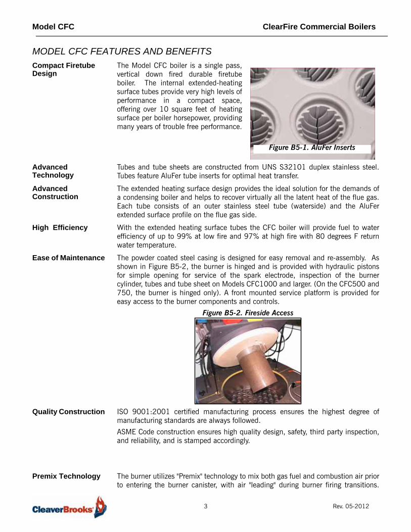
The Model CFC boiler is a single pass,vertical down fired durable firetubeboiler. The internal extended-heatingsurface tubes provide very high levels ofperformance in a compact space,offering over 10 square feet of heatingsurface per boiler horsepower, providingmany years of trouble free performance.
Advanced Technology
Tubes and tube sheets are constructed from UNS S32101 duplex stainless steel.Tubes feature AluFer tube inserts for optimal heat transfer.
Advanced Construction
The extended heating surface design provides the ideal solution for the demands ofa condensing boiler and helps to recover virtually all the latent heat of the flue gas.Each tube consists of an outer stainless steel tube (waterside) and the AluFerextended surface profile on the flue gas side.
High Efficiency With the extended heating surface tubes the CFC boiler will provide fuel to waterefficiency of up to 99% at low fire and 97% at high fire with 80 degrees F returnwater temperature.
Ease of Maintenance The powder coated steel casing is designed for easy removal and re-assembly. Asshown in Figure B5-2, the burner is hinged and is provided with hydraulic pistonsfor simple opening for service of the spark electrode, inspection of the burnercylinder, tubes and tube sheet on Models CFC1000 and larger. (On the CFC500 and750, the burner is hinged only). A front mounted service platform is provided foreasy access to the burner components and controls.
Figure B5-2. Fireside Access
Quality Construction ISO 9001:2001 certified manufacturing process ensures the highest degree ofmanufacturing standards are always followed.
ASME Code construction ensures high quality design, safety, third party inspection,and reliability, and is stamped accordingly.
Premix Technology The burner utilizes "Premix" technology to mix both gas fuel and combustion air priorto entering the burner canister, with air "leading" during burner firing transitions.
Figure B5-1. AluFer Inserts
3 Rev. 05-2012
Model CFC ClearFire Commercial Boilers
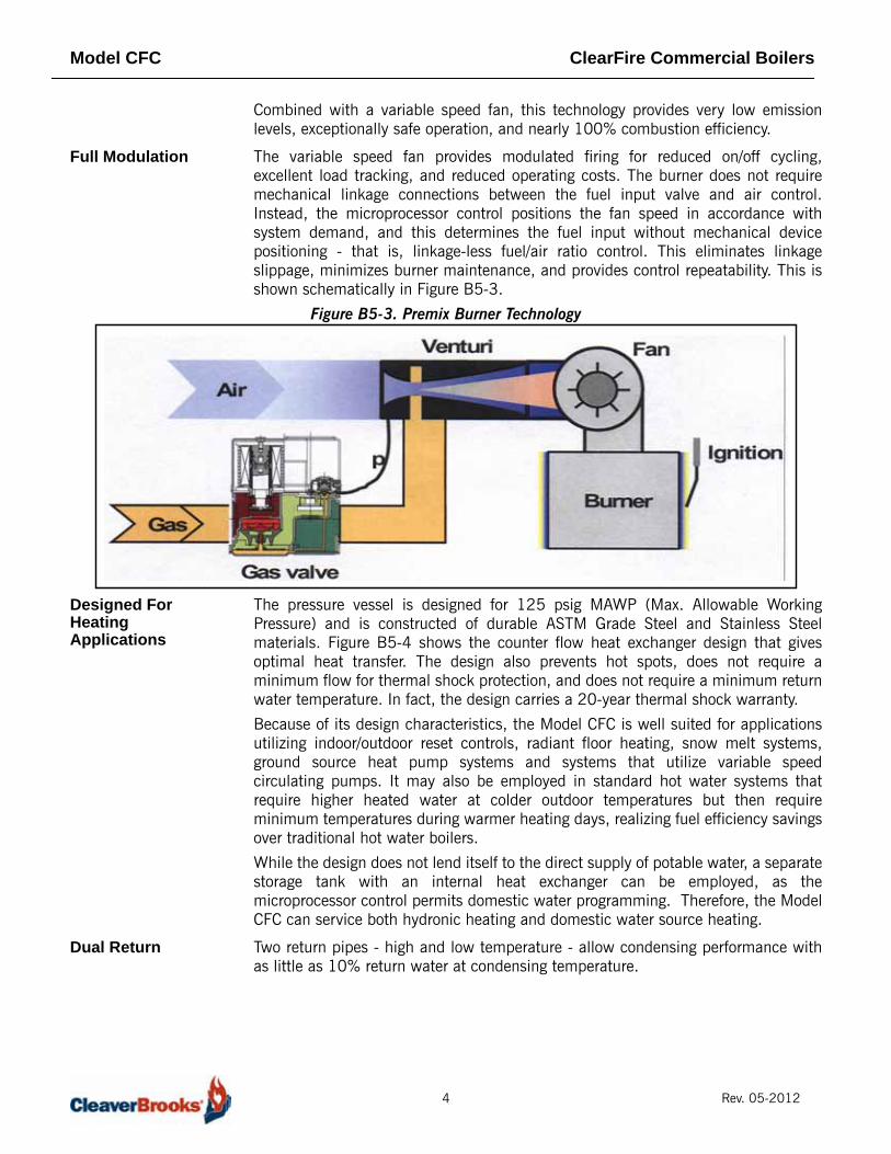
Combined with a variable speed fan, this technology provides very low emissionlevels, exceptionally safe operation, and nearly 100% combustion efficiency.
Full Modulation The variable speed fan provides modulated firing for reduced on/off cycling,excellent load tracking, and reduced operating costs. The burner does not requiremechanical linkage connections between the fuel input valve and air control.Instead, the microprocessor control positions the fan speed in accordance withsystem demand, and this determines the fuel input without mechanical devicepositioning - that is, linkage-less fuel/air ratio control. This eliminates linkageslippage, minimizes burner maintenance, and provides control repeatability. This isshown schematically in Figure B5-3.
Figure B5-3. Premix Burner Technology
Designed For Heating Applications
The pressure vessel is designed for 125 psig MAWP (Max. Allowable WorkingPressure) and is constructed of durable ASTM Grade Steel and Stainless Steelmaterials. Figure B5-4 shows the counter flow heat exchanger design that givesoptimal heat transfer. The design also prevents hot spots, does not require aminimum flow for thermal shock protection, and does not require a minimum returnwater temperature. In fact, the design carries a 20-year thermal shock warranty.
Because of its design characteristics, the Model CFC is well suited for applicationsutilizing indoor/outdoor reset controls, radiant floor heating, snow melt systems,ground source heat pump systems and systems that utilize variable speedcirculating pumps. It may also be employed in standard hot water systems thatrequire higher heated water at colder outdoor temperatures but then requireminimum temperatures during warmer heating days, realizing fuel efficiency savingsover traditional hot water boilers.
While the design does not lend itself to the direct supply of potable water, a separatestorage tank with an internal heat exchanger can be employed, as themicroprocessor control permits domestic water programming. Therefore, the ModelCFC can service both hydronic heating and domestic water source heating.
Dual Return Two return pipes - high and low temperature - allow condensing performance withas little as 10% return water at condensing temperature.
4 Rev. 05-2012

Model CFC ClearFire Commercial Boilers
Figure B5-4. Model CFC Heat Flow and Component Orientation
MODEL CFC PRODUCT OFFERINGInformation in this section applies to condensing hot water boiler sizes ranging from500,000 Btu input through 3,300,000 Btu input for operation on Natural Gas orLP Gas only. Installation is for indoor use only.
Dimensions, ratings, and product information may change to meet current marketrequirements and product improvements. Therefore, use this information as a guide.
Combustion Fan and Premix Gas Valve
Assembly
ControlPanel
“Finned” High Efficiency AluFer
Tubes
ASME CodePressure Vessel
Flue GasOutlet
High Temp.Return
Hot WaterOutlet
Air Vent Connection
BurnerCanister
Low Temp.Return
Safety Relief Valve
5 Rev. 05-2012

Model CFC ClearFire Commercial Boilers
Standard Equipment Equipment described below is for the standard boiler offering:1. The Boiler
A. Each boiler size is designed for a Maximum Allowable Working Pressure(MAWP) of 125 psig (8.6 Bar), constructed in accordance with the ASMECode Section IV and bear the "H" stamp.
B. The insulated boiler is mounted on a base and powder coated steel casingprovided.
C. A drain valve connection is provided at the front bottom for field piping of aboiler drain valve, which can be furnished as an option.
2. Boiler Trim and Controls
• The following items are furnished:
• Probe Type Low Water Cutoff control, manual reset.
• Excess Water Temperature Cutoff, manual reset.
• NTC (negative temp. coefficient) sensor for hot water supply temperature.
• NTC sensor for hot water return temperature.
• ASME Safety Relief Valve set @ 125 psig. (8.6 Bar)
• Combination Temperature/Pressure Gauge.
3. Burner ControlA. The CB Falcon is an integrated burner management and modulation control
with a touch-screen display/operator interface. Its functions include thefollowing:
• Two (2) heating loops with PID load control.• Burner sequencing with safe start check, pre-purge, direct spark ignition (pilot
ignition CFC-3300), and post purge.• Electronic ignition.• Flame Supervision.• Safety shutdown with time-stamped display of lockout condition.• Variable speed control of the combustion fan.• Supervision of low and high gas pressure, air proving, stack back pressure, high
limit, and low water.• First-out annunciator.• Real-time data trending.• (3) pump/auxiliary relay outputs.• Modbus communication capability.• Outdoor temperature reset.• Remote firing rate or setpoint control• Setback/time-of-day setpoint• Lead/Lag for up to 8 boilers
6 Rev. 05-2012

Model CFC ClearFire Commercial Boilers
Figure B5-5. ClearFire Control Panel (1500/1800 shown)
4. Forced Draft BurnerA. The burner is a "Pre-mix" design consisting of a unitized venturi, single body
dual safety gas valve, blower, and burner head.B. Full modulation is accomplished with a variable speed fan for 5:1 turndown
ratio.C. For near flameless combustion, the burner utilizes a Fecralloy-metal fiber
head.D. Noise level at maximum firing is less than 70 dBA regardless of boiler size.E. Operating on Natural Gas, NOx emissions will be less than 20 PPM
regardless of boiler size and the boiler is certified for California and Texas forLow NOx emissions.
F. As an option, the burner is capable of direct vent combustion.G. Ignition of the main flame is via direct spark, utilizing high voltage electrodes
and a separate electrode for flame supervision (CFC-3300 uses gas pilotignition and UV scanner for flame supervision).
H. To ensure adequate combustion air is present prior to ignition, and to ensurethe fan is operating, a combustion air proving switch is furnished.
I. A High Air Pressure Switch is provided to ensure burner lockout if excessiveback pressure due to a blocked stack occurs.
J. For ease of maintenance and inspection, the burner is furnished withhydraulic rods and easy opening lockdown nuts, which permit the burner toswing up (except 500 and 750, which are hinged only). This provides fullaccess to the burner and electrodes, as well, to the tube sheet and tubes.
5. Burner Gas Train
The standard gas train is equipped in accordance with UL certification and complieswith ASME CSD-1. Each burner gas train includes:
FALCON DISPLAY / OPERATOR INTERFACE DEMAND SWITCH
LWCO RESET
7 Rev. 05-2012
Model CFC ClearFire Commercial Boilers
• Low Gas Pressure Interlock, manual reset.
• High Gas Pressure Interlock, manual reset.
• ASME CSD-1 Test Cocks.
• Downstream manual ball type shutoff cock.
• Single body dual safety shutoff gas valve.
Optional Equipment For option details, contact the local authorized Cleaver-Brooks representative. Insummary, here are some of the options that can be provided with the boiler:
A. Dual gas train for quick and easy fuel switchover.B. Reusable air filter.C. Condensate neutralization tank assembly - consists of neutralizing media, filter, and PVC
condensate holding tank with integral drain trap. This assembly can be mounted beneaththe boiler.
D. Outside air intake for direct vent combustion.E. Outdoor temperature sensor for indoor/outdoor control.F. Header temperature sensor for multiple boiler Lead/Lag operation.G. Auxiliary Low Water Control (shipped loose) for field piping by others into the system piping.H. Alarm Horn for safety shutdown.I. Relays for output signal for burner on, fuel valve open.J. Stack Thermometer.K. Stack temperature limit-sensor.L. Auto air vent.M. Boiler drain valve.
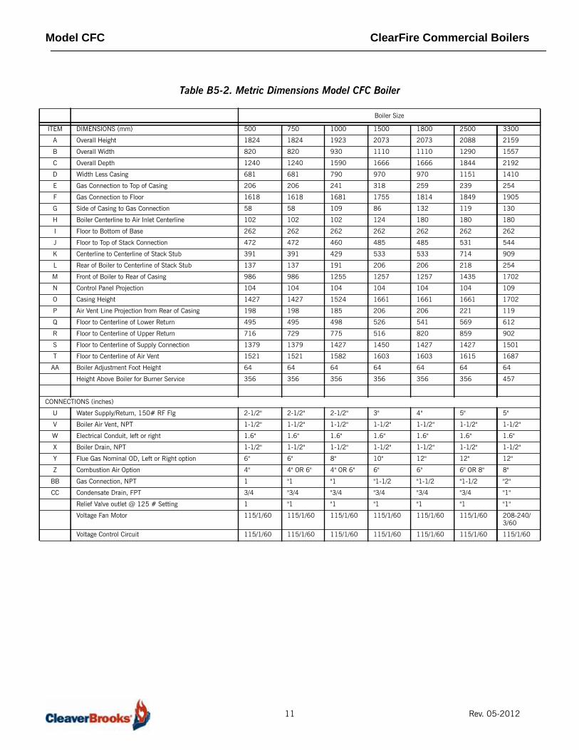
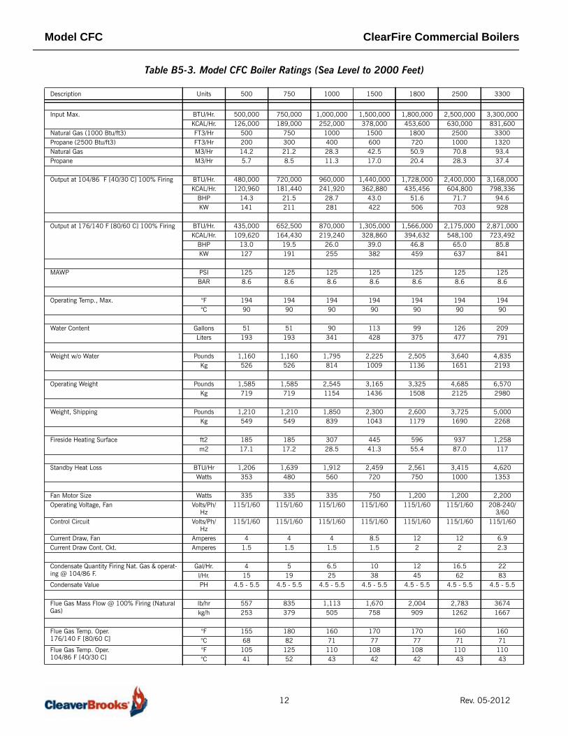
DIMENSIONS AND RATINGSFor layout purposes, the overall dimensions for the Model CFC are shown in TableB5-1 (US Dimensions) and Table B5-2 (Metric Dimensions) including the variouspipe connection sizes for supply and return water, drain, and vent. The performanceratings for the boiler are shown in Table B5-3.
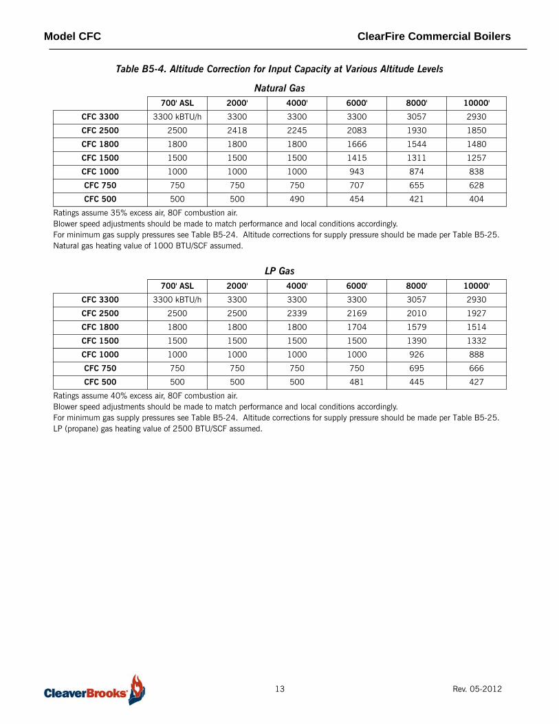
Altitude Relative to the ratings shown, installation of the boiler above 2000 feet elevationwill result in input capacity reduction. Please refer to Table B5-4 for input ratings ofthe boiler at various elevations.
PERFORMANCE DATAEfficiency The Model CFC is a "full condensing" boiler realizing efficiency gain at variable
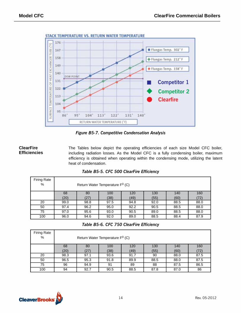
operating conditions. It is designed to extract the latent heat of condensation over agreater range than other designs. This can be seen in Figure B5-7, which depictsnominal stack temperatures of the boiler versus other designs. The nominal point ofcondensation is approximately 132 F (55.5 C). The ClearFire, due to its moreefficient heat transfer design and lower stack temperature, is able to capture thelatent heat of condensation over a broader range.
Fuel-to-water efficiency is relative to specific operating conditions. Operatingefficiency will be greater in the "condensing" mode of operation as noted above, yetwith its inherently greater heat transfer surfaces and superior pre-mix burner, theClearFire’s efficiency under "traditional" hot water conditions is also outstanding.Table B5-6 through Table B5-9 show the guaranteed efficiencies at variousoperating conditions and firing rates for Natural Gas. It should be noted that theefficiency is exceptional at high fire and low fire versus other designs where highefficiency is realized only with low fire or minimal firing rates and low temperaturereturns.
8 Rev. 05-2012

Model CFC ClearFire Commercial Boilers
Figure B5-6. Model CFC Dimensional Views
I
9 Rev. 05-2012

Model CFC ClearFire Commercial Boilers
Table B5-1. U.S. Standard Dimensions Model CFC Boiler
ITEM DIMENSIONS (inches) 500 750 1000 1500 1800 2500 3300
A Overall Height 71.8 71.8 75.7 81.6 81.6 82.2 85.0
B Overall Width 32.3 32.3 36.6 43.7 43.7 50.8 61.3
C Overall Depth 48.8 48.8 62.6 65.6 65.6 72.6 86.3
D Width Less Casing 26.8 26.8 31.1 38.2 38.2 45.3 55.5
E Gas Connection to Top of Casing 8.1 8.1 9.5 12.5 10.2 9.4 10.0
F Gas Connection to Floor 63.7 63.7 66.2 69.1 71.4 72.8 75.0
G Side of Casing to Gas Connection 2.3 2.3 4.3 3.4 5.2 4.7 5.1
H Boiler Centerline to Air Inlet Centerline 4.0 4.0 4.0 4.9 7.1 7.1 7.1
I Floor to Bottom of Base 10.3 10.3 10.3 10.3 10.3 10.3 10.3
J Floor to Top of Stack Connection 18.6 18.6 18.1 19.1 19.1 20.9 21.4
K Centerline to Centerline of Stack Stub 15.4 15.4 16.9 21.0 21.0 28.1 35.8
L Rear of Boiler to Centerline of Stack Stub
5.4 5.4 7.5 8.1 8.1 8.6 10.0
M Front of Boiler to Rear of Casing 38.8 38.8 49.4 49.5 49.5 56.5 67.0
N Control Panel Projection 4.1 4.1 4.1 4.1 4.1 4.1 4.3
O Casing Height 56.2 56.2 60.0 65.4 65.4 65.4 67.0
P Air Vent Line Projection from Rear of Casing
7.8 7.8 7.3 8.1 8.1 8.7 4.7
Q Floor to Centerline of Lower Return 19.5 19.5 19.6 20.7 21.3 22.4 24.1
R Floor to Centerline of Upper Return 28.2 28.7 30.5 20.3 32.3 33.8 35.5
S Floor to Centerline of Supply Connec-tion
54.3 54.3 56.2 57.1 56.2 56.2 59.1
T Floor to Centerline of Air Vent 59.9 59.9 62.3 63.1 63.1 63.6 66.4
AA Boiler Adjustment Foot Height 2.5 2.5 2.5 2.5 2.5 2.5 2.5
Height Above Boiler for Burner Service 14.0 14.0 14.0 14.0 14.0 14.0 18.0
CONNECTIONS
U Water Supply/Return, 150# RF Flg 2-1/2" 2-1/2" 2-1/2" 3" 4" 5" 5"
V Boiler Air Vent, NPT 1-1/2" 1-1/2" 1-1/2" 1-1/2" 1-1/2" 1-1/2" 1-1/2"
W Electrical Conduit, left or right 1.6" 1.6" 1.6" 1.6" 1.6" 1.6" 1.6"
X Boiler Drain, NPT 1-1/2" 1-1/2" 1-1/2" 1-1/2" 1-1/2" 1-1/2" 1-1/2"
Y Flue Gas Nominal OD, Left or Right option
6" 6" 8" 10" 12" 12" 12"
Z Combustion Air Option 4" OR 6" 4" OR 6" 4" OR 6" 6" OR 8" 6" OR 8" 8" 8"
BB Gas Connection, NPT 1" 1" 1" 1-1/2" 1-1/2" 1-1/2" 2"
CC Condensate Drain, FPT 3/4" 3/4" 3/4" 3/4" 3/4" 1" 1"
Relief Valve outlet @ 125 # Setting 1" 1" 1" 1" 1" 1" 1"
Voltage Fan Motor 115/1/60 115/1/60 115/1/60 115/1/60 115/1/60 115/1/60 208-240/3/60
Voltage Control Circuit 115/1/60 115/1/60 115/1/60 115/1/60 115/1/60 115/1/60 115/1/60
10 Rev. 05-2012
Model CFC ClearFire Commercial Boilers
Table B5-2. Metric Dimensions Model CFC Boiler
Boiler Size
ITEM DIMENSIONS (mm) 500 750 1000 1500 1800 2500 3300
A Overall Height 1824 1824 1923 2073 2073 2088 2159
B Overall Width 820 820 930 1110 1110 1290 1557
C Overall Depth 1240 1240 1590 1666 1666 1844 2192
D Width Less Casing 681 681 790 970 970 1151 1410
E Gas Connection to Top of Casing 206 206 241 318 259 239 254
F Gas Connection to Floor 1618 1618 1681 1755 1814 1849 1905
G Side of Casing to Gas Connection 58 58 109 86 132 119 130
H Boiler Centerline to Air Inlet Centerline 102 102 102 124 180 180 180
I Floor to Bottom of Base 262 262 262 262 262 262 262
J Floor to Top of Stack Connection 472 472 460 485 485 531 544
K Centerline to Centerline of Stack Stub 391 391 429 533 533 714 909
L Rear of Boiler to Centerline of Stack Stub 137 137 191 206 206 218 254
M Front of Boiler to Rear of Casing 986 986 1255 1257 1257 1435 1702
N Control Panel Projection 104 104 104 104 104 104 109
O Casing Height 1427 1427 1524 1661 1661 1661 1702
P Air Vent Line Projection from Rear of Casing 198 198 185 206 206 221 119
Q Floor to Centerline of Lower Return 495 495 498 526 541 569 612
R Floor to Centerline of Upper Return 716 729 775 516 820 859 902
S Floor to Centerline of Supply Connection 1379 1379 1427 1450 1427 1427 1501
T Floor to Centerline of Air Vent 1521 1521 1582 1603 1603 1615 1687
AA Boiler Adjustment Foot Height 64 64 64 64 64 64 64
Height Above Boiler for Burner Service 356 356 356 356 356 356 457
CONNECTIONS (inches)
U Water Supply/Return, 150# RF Flg 2-1/2" 2-1/2" 2-1/2" 3" 4" 5" 5"
V Boiler Air Vent, NPT 1-1/2" 1-1/2" 1-1/2" 1-1/2" 1-1/2" 1-1/2" 1-1/2"
W Electrical Conduit, left or right 1.6" 1.6" 1.6" 1.6" 1.6" 1.6" 1.6"
X Boiler Drain, NPT 1-1/2" 1-1/2" 1-1/2" 1-1/2" 1-1/2" 1-1/2" 1-1/2"
Y Flue Gas Nominal OD, Left or Right option 6" 6" 8" 10" 12" 12" 12"
Z Combustion Air Option 4" 4" OR 6" 4" OR 6" 6" 6" 6" OR 8" 8"
BB Gas Connection, NPT 1 "1 "1 "1-1/2 "1-1/2 "1-1/2 "2"
CC Condensate Drain, FPT 3/4 "3/4 "3/4 "3/4 "3/4 "3/4 "1"
Relief Valve outlet @ 125 # Setting 1 "1 "1 "1 "1 "1 "1"
Voltage Fan Motor 115/1/60 115/1/60 115/1/60 115/1/60 115/1/60 115/1/60 208-240/3/60
Voltage Control Circuit 115/1/60 115/1/60 115/1/60 115/1/60 115/1/60 115/1/60 115/1/60
11 Rev. 05-2012
Model CFC ClearFire Commercial Boilers
Table B5-3. Model CFC Boiler Ratings (Sea Level to 2000 Feet)
Description Units 500 750 1000 1500 1800 2500 3300
Input Max. BTU/Hr. 500,000 750,000 1,000,000 1,500,000 1,800,000 2,500,000 3,300,000KCAL/Hr. 126,000 189,000 252,000 378,000 453,600 630,000 831,600
Natural Gas (1000 Btu/ft3) FT3/Hr 500 750 1000 1500 1800 2500 3300Propane (2500 Btu/ft3) FT3/Hr 200 300 400 600 720 1000 1320Natural Gas M3/Hr 14.2 21.2 28.3 42.5 50.9 70.8 93.4Propane M3/Hr 5.7 8.5 11.3 17.0 20.4 28.3 37.4
Output at 104/86 F [40/30 C] 100% Firing BTU/Hr. 480,000 720,000 960,000 1,440,000 1,728,000 2,400,000 3,168,000KCAL/Hr. 120,960 181,440 241,920 362,880 435,456 604,800 798,336
BHP 14.3 21.5 28.7 43.0 51.6 71.7 94.6KW 141 211 281 422 506 703 928
Output at 176/140 F [80/60 C] 100% Firing BTU/Hr. 435,000 652,500 870,000 1,305,000 1,566,000 2,175,000 2,871,000KCAL/Hr. 109,620 164,430 219,240 328,860 394,632 548,100 723,492
BHP 13.0 19.5 26.0 39.0 46.8 65.0 85.8KW 127 191 255 382 459 637 841
MAWP PSI 125 125 125 125 125 125 125BAR 8.6 8.6 8.6 8.6 8.6 8.6 8.6
Operating Temp., Max. °F 194 194 194 194 194 194 194°C 90 90 90 90 90 90 90
Water Content Gallons 51 51 90 113 99 126 209Liters 193 193 341 428 375 477 791
Weight w/o Water Pounds 1,160 1,160 1,795 2,225 2,505 3,640 4,835Kg 526 526 814 1009 1136 1651 2193
Operating Weight Pounds 1,585 1,585 2,545 3,165 3,325 4,685 6,570Kg 719 719 1154 1436 1508 2125 2980
Weight, Shipping Pounds 1,210 1,210 1,850 2,300 2,600 3,725 5,000Kg 549 549 839 1043 1179 1690 2268
Fireside Heating Surface ft2 185 185 307 445 596 937 1,258m2 17.1 17.2 28.5 41.3 55.4 87.0 117
Standby Heat Loss BTU/Hr 1,206 1,639 1,912 2,459 2,561 3,415 4,620Watts 353 480 560 720 750 1000 1353
Fan Motor Size Watts 335 335 335 750 1,200 1,200 2,200Operating Voltage, Fan Volts/Ph/
Hz115/1/60 115/1/60 115/1/60 115/1/60 115/1/60 115/1/60 208-240/
3/60Control Circuit Volts/Ph/
Hz115/1/60 115/1/60 115/1/60 115/1/60 115/1/60 115/1/60 115/1/60
Current Draw, Fan Amperes 4 4 4 8.5 12 12 6.9Current Draw Cont. Ckt. Amperes 1.5 1.5 1.5 1.5 2 2 2.3
Condensate Quantity Firing Nat. Gas & operat-ing @ 104/86 F.
Gal/Hr. 4 5 6.5 10 12 16.5 22l/Hr. 15 19 25 38 45 62 83
Condensate Value PH 4.5 - 5.5 4.5 - 5.5 4.5 - 5.5 4.5 - 5.5 4.5 - 5.5 4.5 - 5.5 4.5 - 5.5
Flue Gas Mass Flow @ 100% Firing (Natural Gas)
lb/hr 557 835 1,113 1,670 2,004 2,783 3674kg/h 253 379 505 758 909 1262 1667
Flue Gas Temp. Oper.176/140 F [80/60 C]
°F 155 180 160 170 170 160 160°C 68 82 71 77 77 71 71
Flue Gas Temp. Oper.104/86 F [40/30 C]
°F 105 125 110 108 108 110 110°C 41 52 43 42 42 43 43
12 Rev. 05-2012
Model CFC ClearFire Commercial Boilers
Table B5-4. Altitude Correction for Input Capacity at Various Altitude Levels
Natural Gas700' ASL 2000' 4000' 6000' 8000' 10000'
CFC 3300 3300 kBTU/h 3300 3300 3300 3057 2930
CFC 2500 2500 2418 2245 2083 1930 1850
CFC 1800 1800 1800 1800 1666 1544 1480
CFC 1500 1500 1500 1500 1415 1311 1257
CFC 1000 1000 1000 1000 943 874 838
CFC 750 750 750 750 707 655 628
CFC 500 500 500 490 454 421 404
Ratings assume 35% excess air, 80F combustion air.Blower speed adjustments should be made to match performance and local conditions accordingly.For minimum gas supply pressures see Table B5-24. Altitude corrections for supply pressure should be made per Table B5-25.Natural gas heating value of 1000 BTU/SCF assumed.
LP Gas700' ASL 2000' 4000' 6000' 8000' 10000'
CFC 3300 3300 kBTU/h 3300 3300 3300 3057 2930
CFC 2500 2500 2500 2339 2169 2010 1927
CFC 1800 1800 1800 1800 1704 1579 1514
CFC 1500 1500 1500 1500 1500 1390 1332
CFC 1000 1000 1000 1000 1000 926 888
CFC 750 750 750 750 750 695 666
CFC 500 500 500 500 481 445 427
Ratings assume 40% excess air, 80F combustion air.Blower speed adjustments should be made to match performance and local conditions accordingly.For minimum gas supply pressures see Table B5-24. Altitude corrections for supply pressure should be made per Table B5-25.LP (propane) gas heating value of 2500 BTU/SCF assumed.
13 Rev. 05-2012
Model CFC ClearFire Commercial Boilers
Figure B5-7. Competitive Condensation Analysis
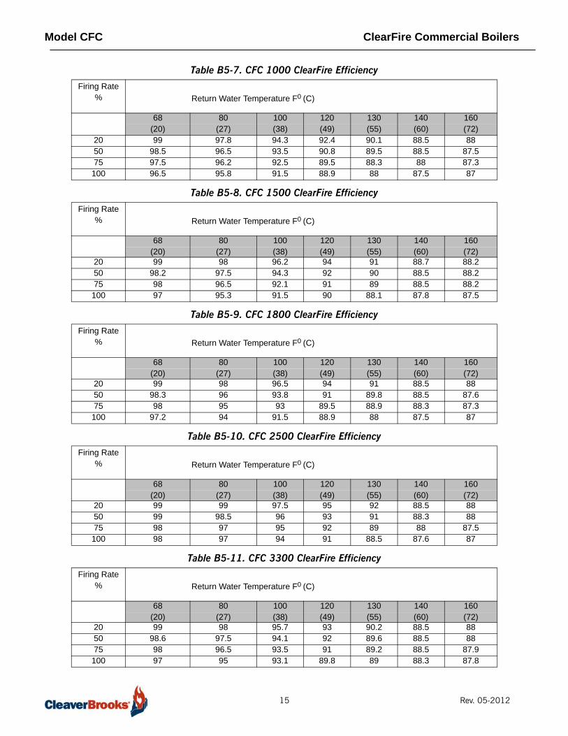
ClearFire Efficiencies
The Tables below depict the operating efficiencies of each size Model CFC boiler,including radiation losses. As the Model CFC is a fully condensing boiler, maximumefficiency is obtained when operating within the condensing mode, utilizing the latentheat of condensation.
Table B5-5. CFC 500 ClearFire Efficiency
Table B5-6. CFC 750 ClearFire Efficiency
Competitor 1
Competitor 2Clearfire
Firing Rate % Return Water Temperature F0 (C)
68 80 100 120 130 140 160(20) (27) (38) (49) (55) (60) (72)
20 99.0 98.8 97.5 94.8 92.0 88.5 88.050 97.4 96.2 95.0 92.2 90.5 88.5 88.075 97.0 95.6 93.0 90.5 89.0 88.5 88.0100 96.0 94.6 92.0 89.0 88.5 88.4 87.9
Firing Rate % Return Water Temperature F0 (C)
68 80 100 120 130 140 160(20) (27) (38) (49) (55) (60) (72)
20 98.3 97.1 93.6 91.7 90 88.0 87.550 96.5 95.3 91.8 89.9 88.5 88.0 87.575 96 94.9 91 89 88 87.5 86.5100 94 92.7 90.5 88.5 87.8 87.0 86
14 Rev. 05-2012
Model CFC ClearFire Commercial Boilers
Table B5-7. CFC 1000 ClearFire Efficiency
Table B5-8. CFC 1500 ClearFire Efficiency
Table B5-9. CFC 1800 ClearFire Efficiency
Table B5-10. CFC 2500 ClearFire Efficiency
Table B5-11. CFC 3300 ClearFire Efficiency
Firing Rate % Return Water Temperature F0 (C)
68 80 100 120 130 140 160(20) (27) (38) (49) (55) (60) (72)
20 99 97.8 94.3 92.4 90.1 88.5 8850 98.5 96.5 93.5 90.8 89.5 88.5 87.575 97.5 96.2 92.5 89.5 88.3 88 87.3100 96.5 95.8 91.5 88.9 88 87.5 87
Firing Rate % Return Water Temperature F0 (C)
68 80 100 120 130 140 160(20) (27) (38) (49) (55) (60) (72)
20 99 98 96.2 94 91 88.7 88.250 98.2 97.5 94.3 92 90 88.5 88.275 98 96.5 92.1 91 89 88.5 88.2100 97 95.3 91.5 90 88.1 87.8 87.5
Firing Rate % Return Water Temperature F0 (C)
68 80 100 120 130 140 160(20) (27) (38) (49) (55) (60) (72)
20 99 98 96.5 94 91 88.5 8850 98.3 96 93.8 91 89.8 88.5 87.675 98 95 93 89.5 88.9 88.3 87.3100 97.2 94 91.5 88.9 88 87.5 87
Firing Rate % Return Water Temperature F0 (C)
68 80 100 120 130 140 160(20) (27) (38) (49) (55) (60) (72)
20 99 99 97.5 95 92 88.5 8850 99 98.5 96 93 91 88.3 8875 98 97 95 92 89 88 87.5100 98 97 94 91 88.5 87.6 87
Firing Rate % Return Water Temperature F0 (C)
68 80 100 120 130 140 160(20) (27) (38) (49) (55) (60) (72)
20 99 98 95.7 93 90.2 88.5 8850 98.6 97.5 94.1 92 89.6 88.5 8875 98 96.5 93.5 91 89.2 88.5 87.9100 97 95 93.1 89.8 89 88.3 87.8
15 Rev. 05-2012
Model CFC ClearFire Commercial Boilers
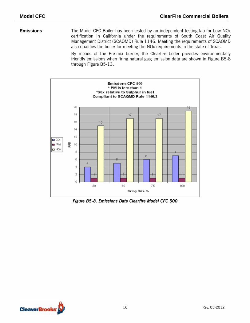
Emissions The Model CFC Boiler has been tested by an independent testing lab for Low NOxcertification in California under the requirements of South Coast Air QualityManagement District (SCAQMD) Rule 1146. Meeting the requirements of SCAQMDalso qualifies the boiler for meeting the NOx requirements in the state of Texas.
By means of the Pre-mix burner, the Clearfire boiler provides environmentallyfriendly emissions when firing natural gas; emission data are shown in Figure B5-8through Figure B5-13.
Figure B5-8. Emissions Data Clearfire Model CFC 500
16 Rev. 05-2012

Model CFC ClearFire Commercial Boilers
Figure B5-9. Emissions Data ClearFire Model CFC 750
Figure B5-10. Emissions Data ClearFire Model CFC 1000
17 Rev. 05-2012

Model CFC ClearFire Commercial Boilers
Figure B5-11. Emissions Data ClearFire Model CFC 1500
Figure B5-12. Emissions Data ClearFire Model CFC 1800
18 Rev. 05-2012

Model CFC ClearFire Commercial Boilers
Figure B5-13. Emissions Data ClearFire Model CFC 2500
Figure B5-14. Emissions Data ClearFire Model CFC 3300
19 Rev. 05-2012

Model CFC ClearFire Commercial Boilers
Noise Level The Model CFC is extremely quiet at all operating levels, does not require any soundlevel modifications to provide ultra low noise levels, and is virtually vibration free.Thus, it is very suitable in applications that demand low noise levels.
Table B5-11 shows the noise levels of the Clearfire at various firing rates.
Table B5-11. Noise Level (dBA) measured 3 feet in front of boiler
ENGINEERING DATABoiler Information The Model CFC boiler is designed for service in any closed hydronic system and can
be used to augment any hot water system. It can be put into operation as a singlestand-alone unit with 5:1 turndown or in multiple units for larger turndown andcapacity.
Clearfire boilers may be utilized in water heating systems with temperatures from40 F (4.4 C) to 195 F (90.5 C); ideal for ground water source heat pumpapplications, etc. Because the Clearfire is a full condensing boiler, low watertemperature (below the dewpoint) restrictions do not apply. In fact, the lower thereturn the better the fuel savings.
Variable temperature differentials can be designed to make use of changing outdoorconditions and thus, the Clearfire is not restricted to a nominal 20 F (10 C)differential. The boiler is designed to withstand thermal stresses with supply andreturn temperature differences up to 100 F (55 C), without the use of a boiler-circulating pump, blend pump or minimum water flow.
Note: The Clearfire does not require a minimum flow or continuous flow through it during operation. However, the load imposed on the boiler must be considered when sizing the system flow so that the flow does not exceed the capacity of the boiler or the demand.
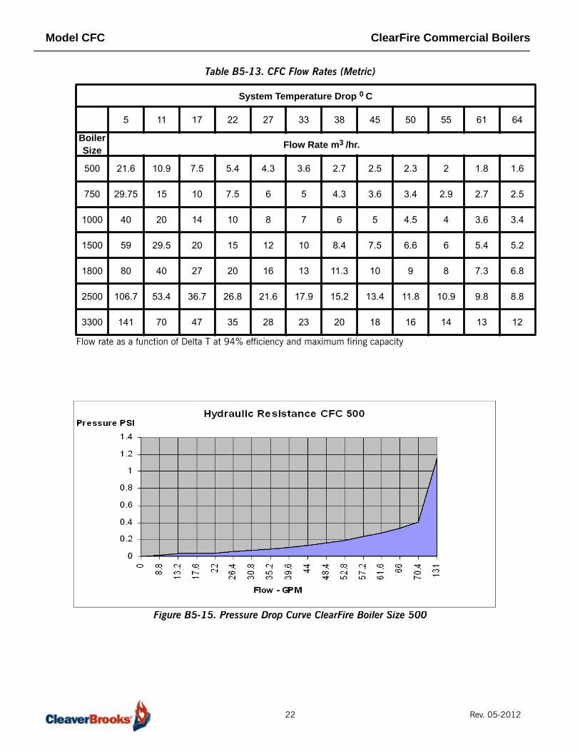
Flow Rates and Pressure Drops
To maintain rated capacity of the boiler, recommended flow rates should not beexceeded as the flow will remove the heat beyond the capacity of the boiler. TableB5-12 through Table B5-13 can be used to determine the full boiler output relativeto system temperature drop and the maximum recommended system pump flow.Knowing the flow rate, the pressure drop through the boiler can be found in FigureB5-14 through Figure B5-19.
System Operating Parameters
To prevent water flashing to steam within the boiler or system, hot water boilersmust operate with proper over-pressure. System over-pressure requirements areshown in Table B5-14.
Note: The ASME Code Section IV limits the maximum setting of the excess temperature control to 210 F (98.9 C) for boilers constructed with stainless steel. This is to ensure that water temperature will not reach the boiling point (steaming) and therefore, so as not to exceed the maximum limit of this control and in compliance with the Code, the operating limit of 195 F
20% Firing 60% Firing 100% FiringCFC 500 39 48 60CFC 750 41 51 62CFC 1000 43 57 66CFC 1500 40 50 64CFC 1800 45 56 66CFC 2500 45 57 68CFC 3300 63 73 78
20 Rev. 05-2012

Model CFC ClearFire Commercial Boilers
(90.5 C) is set for normal boiler operation.
While proper overpressure is required, a means to relieve excess pressure at orbeyond the design pressure of the boiler must be provided. As boiler water isheated, expansion occurs. And this expansion must be accounted for either with anexpansion tank (air filled) or with a bladder type tank. These devices permit thewater pressure to expand outside of the boiler and not impact the pressure vessel orpressure relieving device. But, in accordance with Code, each boiler is equippedwith an ASME approved safety relieving device should pressure build-up occur (SeeTable B5-16 and Table B5-15).
Air Venting The elimination of entrained air is required. It is recommended that each unit bepiped to an expansion tank. If this is not possible, then an auto air vent should beprovided on the vent connection of the boiler. The caveat in using an auto vent isthat free oxygen can be introduced to the vesel as the boiler cools, or in someinstances the vent can become plugged.
Table B5-12. CFC Flow Rates
System Temperature Drop 0 F
10 20 30 40 50 60 70 80 90 100 110 120
Boiler Size Flow Rate GPM
500 95 48 33 24 19 16 12 11 10.5 9 8 7
750 131 66 44 33 26 22 19 16 15 13 12 11
1000 176 88 59 44 35 29 25 22 20 18 16 15
1500 260 130 87 65 52 43 37 33 29 26 24 23
1800 351 176 117 88 70 59 50 44 39 35 32 30
2500 470 235 157 118 95 79 67 59 52 48 43 39
3300 620 310 207 155 124 103 89 78 69 62 56 52
Flow rate as a function of Delta T at 94% efficiency and maximum firing capacity
21 Rev. 05-2012
Model CFC ClearFire Commercial Boilers
Table B5-13. CFC Flow Rates (Metric)
Figure B5-15. Pressure Drop Curve ClearFire Boiler Size 500
System Temperature Drop 0 C
5 11 17 22 27 33 38 45 50 55 61 64
Boiler Size Flow Rate m3 /hr.
500 21.6 10.9 7.5 5.4 4.3 3.6 2.7 2.5 2.3 2 1.8 1.6
750 29.75 15 10 7.5 6 5 4.3 3.6 3.4 2.9 2.7 2.5
1000 40 20 14 10 8 7 6 5 4.5 4 3.6 3.4
1500 59 29.5 20 15 12 10 8.4 7.5 6.6 6 5.4 5.2
1800 80 40 27 20 16 13 11.3 10 9 8 7.3 6.8
2500 106.7 53.4 36.7 26.8 21.6 17.9 15.2 13.4 11.8 10.9 9.8 8.8
3300 141 70 47 35 28 23 20 18 16 14 13 12
Flow rate as a function of Delta T at 94% efficiency and maximum firing capacity
22 Rev. 05-2012

Model CFC ClearFire Commercial Boilers
Figure B5-16. Pressure Drop Curve ClearFire Boiler Size 750
Figure B5-17. Pressure Drop Curve ClearFire Boiler Size 1000
23 Rev. 05-2012

Model CFC ClearFire Commercial Boilers
Figure B5-18. Pressure Drop Curve ClearFire Boiler Size 1500
Figure B5-19. Pressure Drop Curve ClearFire Boiler Size 1800
24 Rev. 05-2012
Model CFC ClearFire Commercial Boilers
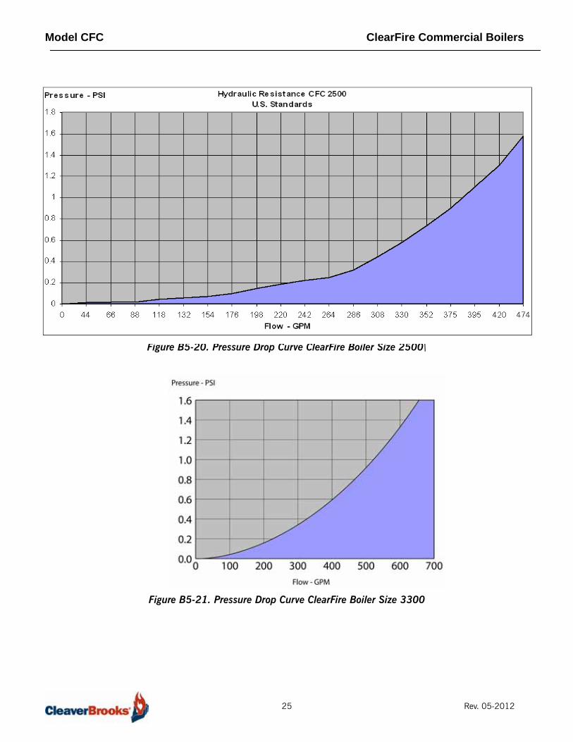
Figure B5-20. Pressure Drop Curve ClearFire Boiler Size 2500\
Figure B5-21. Pressure Drop Curve ClearFire Boiler Size 3300
25 Rev. 05-2012
Model CFC ClearFire Commercial Boilers
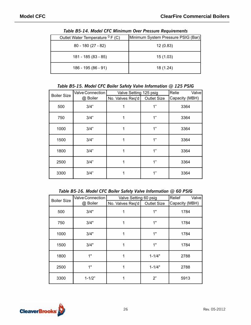
Table B5-14. Model CFC Minimum Over Pressure Requirements
Table B5-15. Model CFC Boiler Safety Valve Information @ 125 PSIG
Table B5-16. Model CFC Boiler Safety Valve Information @ 60 PSIG
Outlet Water Temperature 0 F (C) Minimum System Pressure PSIG (Bar)
80 - 180 (27 - 82) 12 (0.83)
181 - 185 (83 - 85) 15 (1.03)
186 - 195 (86 - 91) 18 (1.24)
Boiler SizeValve Connection
@ BoilerValve Setting 125 psig Relie Valve
Capacity (MBH)No. Valves Req'd Outlet Size
500 3/4” 1 1” 3364
750 3/4” 1 1” 3364
1000 3/4” 1 1” 3364
1500 3/4” 1 1” 3364
1800 3/4” 1 1” 3364
2500 3/4” 1 1” 3364
3300 3/4” 1 1” 3364
Boiler SizeValve Connection
@ BoilerValve Setting 60 psig Relief Valve
Capacity (MBH)No. Valves Req'd Outlet Size
500 3/4" 1 1" 1784
750 3/4" 1 1" 1784
1000 3/4" 1 1" 1784
1500 3/4" 1 1" 1784
1800 1" 1 1-1/4" 2788
2500 1" 1 1-1/4" 2788
3300 1-1/2” 1 2” 5913
26 Rev. 05-2012

Model CFC ClearFire Commercial Boilers
Water Treatment Even though hot water systems are "closed", some amount of make-up water (up to10%) will be introduced. This more often than not happens from seal leaks ofpumps, or other minimal leaks from valves etc., that go unnoticed. Therefore,proper water chemistry of a hot water boiler is necessary for good operation andlongevity, particularly to ensure that free oxygen is removed to prevent watersidecorrosion (see Table B5-17).
Table B5-17. Model CFC Water Chemistry Requirements in accordance with ABMA
Glycol The Model CFC boiler may be operated with a solution of glycol and water. Whereglycols are added, the system must first be cleaned and flushed. Correct glycolselection and regular monitoring of the in-use concentration and its stability isessential to ensure adequate, long-term freeze protection, as well as protectionfrom the effects of glycol-derived corrosion resulting from glycol degradation.
Typically, ethylene glycol is used for freeze protection, but other alternatives exist,such as propylene glycol. Glycol reduces the water-side heat capacity (lowerspecific heat than 100% water) and can reduce the effective heat transfer to thesystem. Because of this, design flow rates and pump selections should be sizedwith this in mind.
Generally, corrosion inhibitors are added to glycol systems. However, all glycolstend to oxidize over time in the presence of oxygen, and when heated, formaldehydes, acids, and other oxidation products. Whenever inadequate levels ofwater treatment buffers and corrosion inhibitors are used, the resulting water glycolmixture pH may be reduced to below 7.0 (frequently reaching 5) and acid corrosionresults. Thus, when pH levels drop below 7.0 due to glycol degradation the onlyalternative is to drain, flush, repassivate, and refill with a new inhibited glycolsolution.
The following recommendations should be adhered to in applying ClearFire modelCFC boilers to hydronic systems using glycol:
1) Maximum allowable antifreeze proportion (volume %): 50% antifreeze (glycol)50% water
Parameter Limit
Glycol 50%
pH 8.3 - 9.5
Nitrates 50 mg/liter
Sulphates 50 mg/liter
Chloride 30 mg/liter
Oxygen 0.1 mg/liter
Specific Conductivity 3500 mmho/cm
Total Hardness <10 ppm
27 Rev. 05-2012
Model CFC ClearFire Commercial Boilers
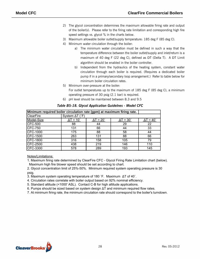
2) The glycol concentration determines the maximum allowable firing rate and outputof the boiler(s). Please refer to the firing rate limitation and corresponding high firespeed settings vs. glycol % in the charts below.
3) Maximum allowable boiler outlet/supply temperature: 185 deg F (85 deg C).4) Minimum water circulation through the boiler:
a) The minimum water circulation must be defined in such a way that thetemperature difference between the boiler outlet/supply and inlet/return is amaximum of 40 deg F (22 deg C), defined as DT (Delta T). A DT Limit
algorithm should be enabled in the boiler controller.b) Independent from the hydraulics of the heating system, constant water
circulation through each boiler is required. (Requires a dedicated boilerpump if in a primary/secondary loop arrangement.) Refer to table below forminimum boiler circulation rates.
5) Minimum over-pressure at the boiler:For outlet temperatures up to the maximum of 185 deg F (85 deg C), a minimumoperating pressure of 30 psig (2.1 bar) is required.
6) pH level should be maintained between 8.3 and 9.5
Table B5-18. Glycol Application Guidelnes - Model CFC
Minimum required boiler circulation rate (gpm) at maximum firing rate.ClearFire System ΔT (˚F)Model-Size ΔT = 10˚ ΔT = 20˚ ΔT = 30˚ ΔT = 40˚CFC-500 88 44 29 22CFC-750 131 66 44 33CFC-1000 175 88 58 44CFC-1500 263 131 88 66CFC-1800 316 158 105 79CFC-2500 438 219 146 110CFC-3300 578 289 193 145
Notes/Limitations:1. Maximum firing rate determined by ClearFire CFC - Glycol Firing Rate Limitation chart (below). Maximum high fire blower speed should be set according to chart.2. Glycol concentration limit of 25%-50%. Minimum required system operating pressure is 30 psig.3. Maximum system operating temperature of 180 ˚F. Maximum ΔT of 40˚.4. Circulation rates correlate with boiler output based on 92% nominal efficiency.5. Standard altitude (<1000' ASL). Contact C-B for high altitude applications.6. Pumps should be sized based on system design ΔT and minimum required flow rates.7. At minimum firing rate, the minimum circulation rate should correspond to the boiler's turndown.
28 Rev. 05-2012

Model CFC ClearFire Commercial Boilers
Table B5-19. Max Firing Rate vs. Glycol Concentration
Table B5-20. HF Speed Settings vs. Glycol Content
CondensationAs the Model CFC boiler is a full condensing boiler, condensation will develop duringstartup of a cold boiler or at any time when the return water temperature is belowthe dew point or approximately 132 F (55.5 C).
The condensation collects in the lower portion of the boiler from the tube surfacesand from the stack, and must be discharged to a drain. A Condensate trap must bepiped on the boiler and must be field piped to either a drain or to the optionalcondensate treatment kit. Table B5-21 provides the amount of condensation thatwill form when the boiler operates in the full condensing mode.
29 Rev. 05-2012

Model CFC ClearFire Commercial Boilers
Table B5-21. Model CFC Maximum Condensation
As prescribed by local codes, this condensate may be discharged directly to thedrain or treated using an optional treatment assembly. Figure B5-21 depicts pipingwithout the treatment assembly and Figure B5-22 shows the optional treatmentassembly.
Condensate Piping for Multiple Boilers
The number of condensate treatment tanksrequired for multiple boiler installations dependson the total amount of condensate produced bythe system. As a general rule, CB recommendsone tank per 5 million BTU/hr of boiler capacity(5.0 MMBTU/hr). Model CFC capacities are inTable B5-22.
See Figure B5-23 and Figure B5-24 for suggestedpiping. A drain trap is built into the condensatetank. Make-up water must be supplied at theconnection shown in order to prevent flue gas fromentering an idle boiler. An internal float in the condensate tank activates the make-up water valve.
Figure B5-22. Condensate Piping Direct To Drain
Boiler SizeGallons Per Hour - GPH(Liters Per Hour - L/H)
500 3.5 (13.2)
750 5 (18.9)
1000 7 (26.5)
1500 9 (34)
1800 12 (45.4)
2500 17 (64.4)
3300 22 (83.3)Boiler Operating @ maximum in full condensing mode.
Table B5-22. CFC capacitiesCFC Model BTU/hr
3300 3,300,0002500 2,500,0001800 1,800,0001500 1,500,0001000 1,000,000750 750,000500 500,000
1
2
3
1. Removable front2. Min. 6” water trap3. Plastic drain pipe
30 Rev. 05-2012

Model CFC ClearFire Commercial Boilers
Figure B5-23. Optional Condensate Treatment Assembly
NoticeIf a treatment kit is utilized, clearance at the front of the boiler must be provided for servicing the assembly and for periodically adding the neutralizing granules.
Figure B5-24. Condensate Piping for Multiple Boilers
Neutralization media
To drain
Neutralization tankDrain trap
Condensate in
Float valve for makeup water
To Drain
1/4" O.D. Make-up Water SupplyCondensate Drain Trap
Neutralization Tank
31 Rev. 05-2012

Model CFC ClearFire Commercial Boilers
Figure B5-25. Condensate Treatment Tank for Multiple Boilers
Gas Fuel Connections
The local Gas Company should be consulted for the requirements for installationand inspection of gas supply piping. Installation of gas supply piping and ventingmust be in accordance with all applicable engineering guidelines and regulatorycodes. All connections made to the boiler must be arranged so that all componentsare accessible for inspection, cleaning, and maintenance.
A drip leg should be installed in the supply line before the connection to the boiler.The drip leg should be at least as large as the gas piping connection on the boiler.See Figure B5-25, and Figure B5-26 for piping suggestions.
To Drain
Condensate Drain Trap
1" NPT Minimum Header Size(Use PVC Pipe or other Nonferrous Material)
Neutralization Tank
12” Minimum
Neutralization Media
Cond. tank can bemounted under boiler
32 Rev. 05-2012
Model CFC ClearFire Commercial Boilers
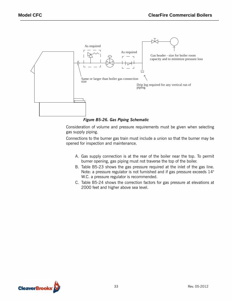
Figure B5-26. Gas Piping Schematic
Consideration of volume and pressure requirements must be given when selectinggas supply piping.
Connections to the burner gas train must include a union so that the burner may beopened for inspection and maintenance.
A. Gas supply connection is at the rear of the boiler near the top. To permitburner opening, gas piping must not traverse the top of the boiler.
B. Table B5-23 shows the gas pressure required at the inlet of the gas line.Note: a pressure regulator is not furnished and if gas pressure exceeds 14"W.C. a pressure regulator is recommended.
C. Table B5-24 shows the correction factors for gas pressure at elevations at2000 feet and higher above sea level.
Same or larger than boiler gas connectionsize
Drip leg required for any vertical run ofpiping
As required
Gas header - size for boiler roomcapacity and to minimize pressure loss
As required
33 Rev. 05-2012

Model CFC ClearFire Commercial Boilers
Figure B5-27. Gas Header Piping
ModelCFC
Regulator
ModelCFC
ModelCFC
ModelCFC
Header Pipe
MeterFrom
Gas Header Piping, Typical
Gas Strainer
Relief ValveSee Note 5
Manual Shut Off
See Note 1
NOTES:1. Dedicated gas pressure regulator required for each boiler.2. Refer to local fuel gas codes when applicable.3. Header to be sized for room capacity.4. Provision required for measuring gas supply pressure at boiler.5. Relief valve required if gas supply pressure >1 psig.
34 Rev. 05-2012
Model CFC ClearFire Commercial Boilers
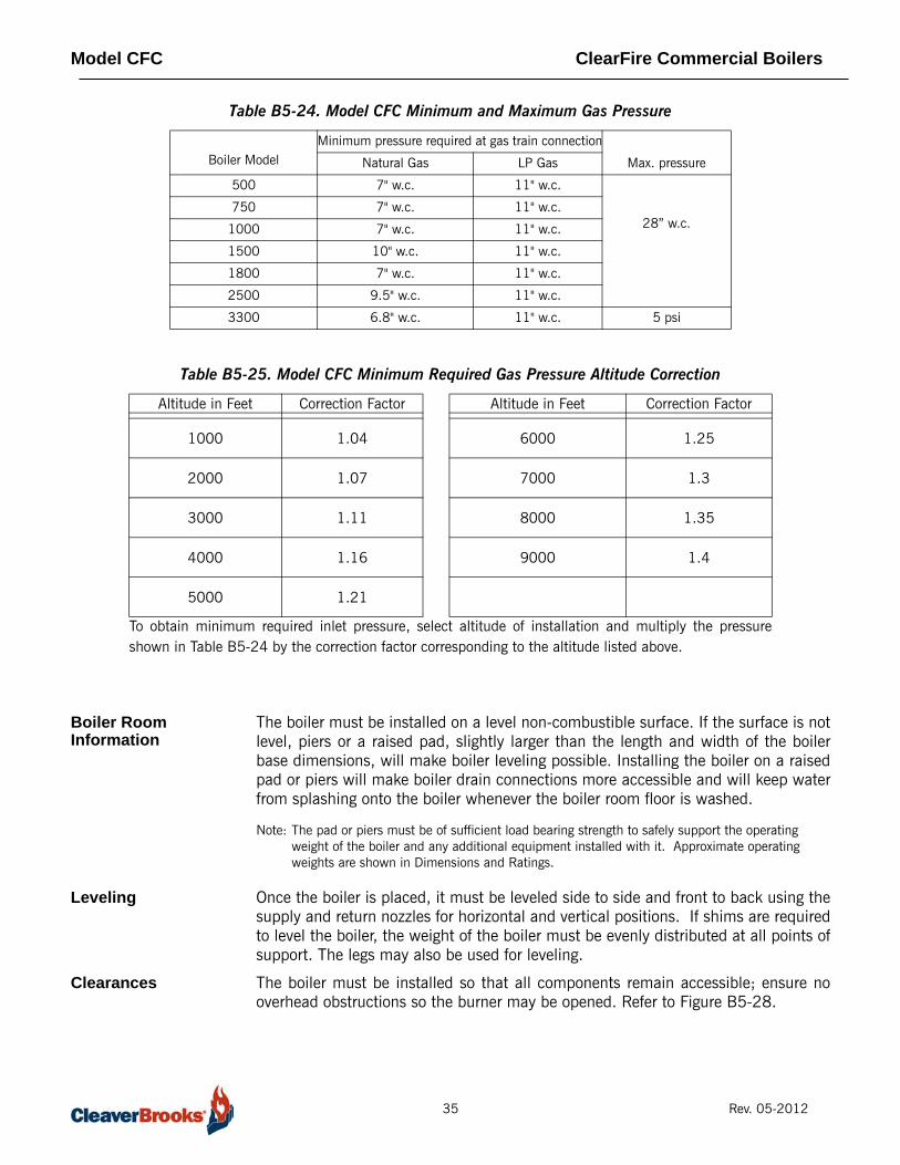
Table B5-24. Model CFC Minimum and Maximum Gas Pressure
Table B5-25. Model CFC Minimum Required Gas Pressure Altitude Correction
Boiler Room Information
The boiler must be installed on a level non-combustible surface. If the surface is notlevel, piers or a raised pad, slightly larger than the length and width of the boilerbase dimensions, will make boiler leveling possible. Installing the boiler on a raisedpad or piers will make boiler drain connections more accessible and will keep waterfrom splashing onto the boiler whenever the boiler room floor is washed.
Note: The pad or piers must be of sufficient load bearing strength to safely support the operating weight of the boiler and any additional equipment installed with it. Approximate operating weights are shown in Dimensions and Ratings.
Leveling Once the boiler is placed, it must be leveled side to side and front to back using thesupply and return nozzles for horizontal and vertical positions. If shims are requiredto level the boiler, the weight of the boiler must be evenly distributed at all points ofsupport. The legs may also be used for leveling.
Clearances The boiler must be installed so that all components remain accessible; ensure nooverhead obstructions so the burner may be opened. Refer to Figure B5-28.
Boiler ModelMinimum pressure required at gas train connection
Max. pressureNatural Gas LP Gas
500 7" w.c. 11" w.c.
28” w.c.750 7" w.c. 11" w.c.
1000 7" w.c. 11" w.c.
1500 10" w.c. 11" w.c.
1800 7" w.c. 11" w.c.
2500 9.5" w.c. 11" w.c.
3300 6.8" w.c. 11" w.c. 5 psi
Altitude in Feet Correction Factor Altitude in Feet Correction Factor
1000 1.04 6000 1.25
2000 1.07 7000 1.3
3000 1.11 8000 1.35
4000 1.16 9000 1.4
5000 1.21
To obtain minimum required inlet pressure, select altitude of installation and multiply the pressureshown in Table B5-24 by the correction factor corresponding to the altitude listed above.
35 Rev. 05-2012

Model CFC ClearFire Commercial Boilers
Figure B5-28. Model CFC Minimum Room Clearance Dimensions
Seismic Legs Seismic mounting details shown below.
Figure B5-29. CFC Seismic Mounting
DIM Inches
Top Clearance A 14
Side Clearance B 20
Backway C 20
Front D 36
Between Boilers E 3
C
B
D
B
E
CFC 500-2500 CFC 3300
36 Rev. 05-2012
Model CFC ClearFire Commercial Boilers
Hot Water Piping Primary/secondary pumps are not necessary with the Model CFC boiler. As itsdesign is such that no minimum flow is required, variable speed or on/off pumpsmay be employed in the piping scheme.
Typical piping arrangements are shown in figures B5-33 through B5-45.
Note: These diagrams are generic and are not intended for use in a specific design without consultation with your local Cleaver-Brooks sales representative
37 Rev. 05-2012

e
Domestic ColdWater In
DomesticWater
DomesticWater Supply
Figure B5-33. No primary Loop with Domestic Water and 2-Way Divert Valv
ClearFire Full
CondensingClearFire FullCondensing
To Condensate Drain
To Sanitary Drain
System Returns
DomesticWater Pump
Return Header
Boiler Drain
Heating SystemPumps
System Supply & Returns
System SupplyHeader
ExpansionTank
WaterMakeup
2-Way DivertingValveOn/Off Valve

Figure B5-36. Two Boilers and Three Variable Temperature Zones (No Primary Loop)
ClearFire
ClearFire
P P
T T
BV1 B1
T T
BV1 B1
T T
BV1 B1
CWS
Filling LoopRemovable
TankExpansion
Return Return
Run condensate drain toadjacent drain (or via optional
condensate pumping unit)
Drain
Flow
PrefabricatedHeader
Back Pressure
RadiantHeating Load
Valve

Figure B5-37. Two-Pipe Primary/Secondary Piping with Domestic Hot Water
Boiler
Heating Load
A
Heating Load
B
Heating Load
C
1 BOILER OUTLET (SUPPLY)
2 BOILER INLET (RETURN)
3 SECONDARY CONNECTION
4 ISOLATION VALVES
5 PURGE COCKS
6 AIR SEPARATOR WITH AUTOMATIC AIR VENT
7 DIAPHRAGM EXPANSION TANK WITH FILL VALVE
8 BALANCING VALVES (SQUARE HEAD COCKS)
9 SYSTEM CIRCULATOR
10 SECONDARY CIRCULATORS INJECTION PUMP
11 FLOW/CHECK VALVES (TO PREVENT GRAVITY
10
11
8
10 5
8
8
3
5
10
3
11 105
8
3
5
1
2
69
4
7
(FIXED OR VARIABLE SPEED)
OR PRESSURE-DROP-INDUCED FLOW IN SECONDAY CIRCUITS)
12" MAX APART AT ALL SECONDARY CONNECTIONSTO PREVENT FORCED FLOW IN SECONDARYCAUSED BY PRESSURE DROP THROUGH PIPINGBETWEEN CONNECTIONS
TEMPERATURE CONTROL BY SECONDARYCIRCULATION ONLY
TEMPERATURE CONTROL USING MIXINGVALVE
TEMPERATURE/HEAT INPUT CONTROLUSING INJECTION PUMPING
AB
C
13
12
12 DOMESTIC PUMP
13 DOMESTIC WATER TANK
4

Figure B5-38. Two-Pipe Primary/Secondary Piping
Boiler
Heating Load
A
Heating Load
B
Heating Load
C
1 BOILER OUTLET (SUPPLY)
2 BOILER INLET (RETURN)
3 SECONDARY CONNECTION
4 ISOLATION VALVES
5 PURGE COCKS
6 AIR SEPARATOR WITH AUTOMATIC AIR VENT
7 DIAPHRAGM EXPANSION TANK WITH FILL VALVE
8 BALANCING VALVES (SQUARE HEAD COCKS)
9 SYSTEM CIRCULATOR
10 SECONDARY CIRCULATORS INJECTION PUMP
11 FLOW/CHECK VALVES (TO PREVENT GRAVITY
10
11
8
10 5
8
8
3
5
10
3
11 105
8
3
5
1
2
69
4
7
(FIXED OR VARIABLE SPEED)
OR PRESSURE-DROP-INDUCED FLOW IN SECONDAY CIRCUITS)
4 12" MAX APART AT ALL SECONDARY CONNECTIONSTO PREVENT FORCED FLOW IN SECONDARYCAUSED BY PRESSURE DROP THROUGH PIPINGBETWEEN CONNECTIONS
TEMPERATURE CONTROL BY SECONDARYCIRCULATION ONLY
TEMPERATURE CONTROL USING MIXINGVALVE
TEMPERATURE/HEAT INPUT CONTROLUSING INJECTION PUMPING
AB
C
4

Figure B5-39. No Primary Loop
ClearFire Full
CondensingClearFire FullCondensing
To Condensate Drain
To Sanitary Drain
System Returns
Return Header
Boiler Drain
Heating SystemPumps
System Supply & Returns
System SupplyHeader
ExpansionTank
WaterMakeup
Y10.2Y10.1
VK-1 VK-2
Y10.1 Motorized ShutoffY10.2 Motorized ShutoffVK-1 3-Way Mixed Circuit VK-2 3-Way Mixed Circuit
Back PressueValve

Figure B5-40. Domestic Water Heating, No Primary Loop
ClearFire FullCondensing
ClearFire FullCondensing
To Condensate Drain
To Sanitary Drain
System Returns
Boiler Drain
ExpansionTank
WaterMakeup
Air Vent Line PrimaryPump
StandbyPump
Surge Tank

Figure B5-41. Domestic Water with On/Off and 3-Way Valves
ClearFire Full
CondensingClearFire FullCondensing
To Condensate Drain
To Sanitary DrainSystem Returns
Domestic ColWater In
DomesticWater
DomesticWater Pump
Return Header
Boiler Drain
DomesticWater Supply
Heating SystemPumps
System Supply & Returns
System SupplyHeader
ExpansionTank
WaterMakeup
On-OffValves

Figure B5-42. Piping ‘Hybrid’ Boilers
CFC
1 BOILER OUTLET (SUPPLY)
2 BOILER INLET (RETURN)
3 ISOLATION VALVES
4 PURGE COCKS
5 AIR SEPARATOR WITH AUTOMATIC AIR VENT
6 DIAPHRAGM EXPANSION TANK WITH FILL VALVE
7 FLOW/CHECK VALVES
8 SYSTEM CIRCULATOR
3
4
58
6
Supply Return
FLX
2
3
1
7 3
130 F
150 F
Sensor
33
3 3
3
3
7

Figure B5-43. ‘Hybrid’ Boilers with Domestic Water
CFC
1 BOILER OUTLET (SUPPLY)
2 BOILER INLET (RETURN)
3 SECONDARY CONNECTION
4 ISOLATION VALVES
5 PURGE COCKS
6 AIR SEPARATOR WITH AUTOMATIC AIR VENT
7 DIAPHRAGM EXPANSION TANK WITH FILL VALVE
8 FLOW/CHECK VALVES
9 SYSTEM CIRCULATOR
5
69
7
3 12" MAX APART AT ALL SECONDARY CONNECTIONSTO PREVENT FORCED FLOW IN SECONDARYCAUSED BY PRESSURE DROP THROUGH PIPINGBETWEEN CONNECTIONS
Supply
Return
FLX
2
4
1
8 4
130 F
150 F
Sensor
Hot WaterOutlet
Cold WaterSupply
10 DOMESTIC PUMP
4
4
4
4
4
1
2
8
10
4
3

Figure B5-34. 2 Pipe System, Typical (reverse-return)
CFC
2
1
1 PRIMARY ZONE (WITH THERMOSTAT)-THERMOSTAT CONTROLS BOILER AND CIRCULATOR.
2 HEATING UNITS WITHTHERMOSTATIC VALVES.
4
8
5
4
7
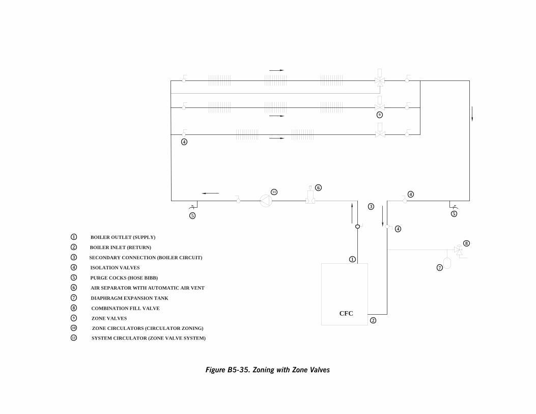
Figure B5-35. Zoning with Zone Valves
CFC
1 BOILER OUTLET (SUPPLY)
2 BOILER INLET (RETURN)
4
5
116
3
1
2
9
3 SECONDARY CONNECTION (BOILER CIRCUIT)
4 ISOLATION VALVES
5 PURGE COCKS (HOSE BIBB)
6 AIR SEPARATOR WITH AUTOMATIC AIR VENT
7 DIAPHRAGM EXPANSION TANK
8 COMBINATION FILL VALVE
9 ZONE VALVES
10 ZONE CIRCULATORS (CIRCULATOR ZONING)
11 SYSTEM CIRCULATOR (ZONE VALVE SYSTEM)
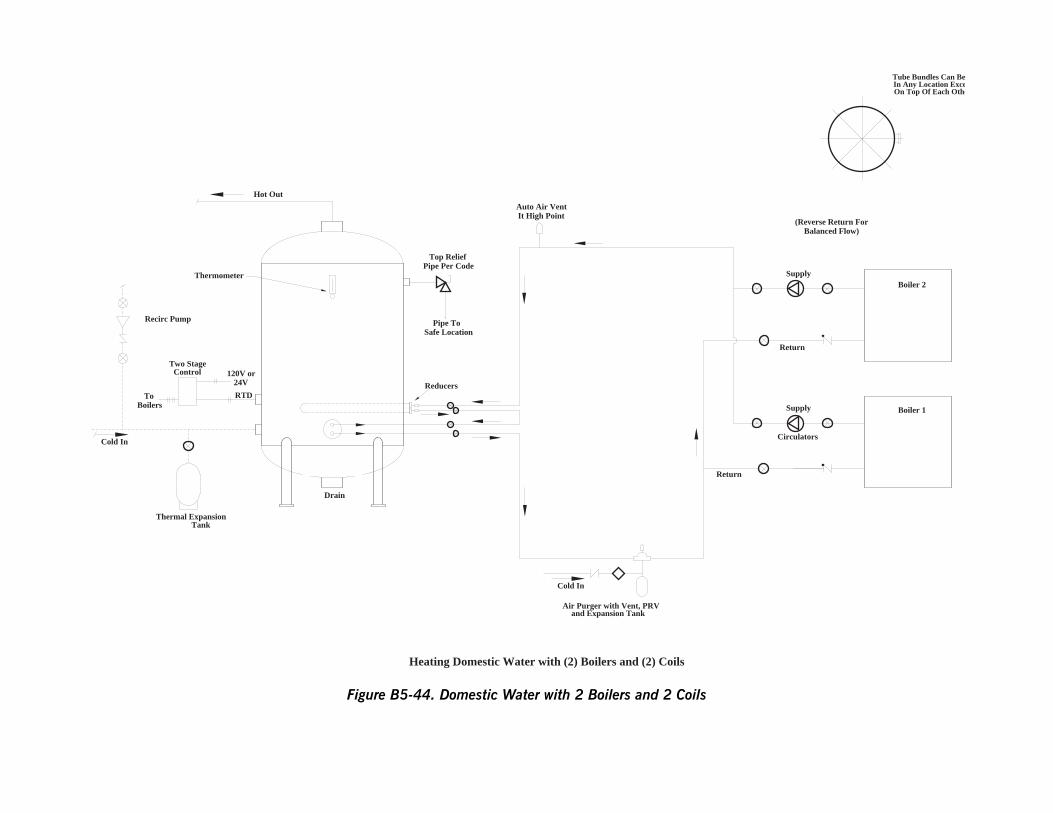
(Reverse Return ForBalanced Flow)
Boiler 2
Boiler 1
Circulators
Tube Bundles Can BeIn Any Location ExceOn Top Of Each Othe
Supply
Supply
Return
Figure B5-44. Domestic Water with 2 Boilers and 2 Coils
ToBoilers
RTD
120V or24V
ControlTwo Stage
Cold In
Recirc Pump
Drain
TankThermal Expansion
Hot Out
Thermometer
Pipe ToSafe Location
Top ReliefPipe Per Code
Cold In
Air Purger with Vent, PRVand Expansion Tank
Reducers
Auto Air VentIt High Point
Return
Heating Domestic Water with (2) Boilers and (2) Coils

Model CFC ClearFire Commercial Boilers
Boiler Room Combustion and Ventilation Air
The boiler(s) must be supplied with adequate quantities of uncontaminated air tosupport proper combustion and equipment ventilation. Air shall be free of chlorides,halogens, fluorocarbons, construction dust or other contaminants that aredetrimental to the burner/boiler. If these contaminants are present, we recommendthe use of direct vent combustion provided the outside air source isuncontaminated.
Combustion air can be supplied by means of conventional venting, wherecombustion air is drawn from the area immediately surrounding the boiler (boilerroom must be positive pressure), or with direct vent (direct vent combustion) whereair is drawn directly from the outside. All installations must comply with local Codesand with NFPA 54 (the National Fuel Gas Code - NFGC) for the U.S. and forCanada, CAN/CGA B 149.1 and B 149.2.
Note: A boiler room exhaust fan is not recommended as this type of device can cause a negative pressure in the boiler room if using a conventional air intake.
In accordance with NFPA54, the required volume of indoor air shall be determinedin accordance with the "Standard Method" or "Known Air Infiltration Rate Method.Where the air infiltration rate is known to be less than 0.40 Air Changes per Hour,the Known Air Infiltration Rate Method shall be used. (See Section 8.3 in theNFPA54 Handbook for additional information.)
Combustion Air Supply - Unconfined Spaces (For U.S. Installations Only)
A. All Air From Inside the Building - If additional combustion air is drawn frominside the building (the mechanical equipment room does not receive airfrom outside via louvers or vent openings and the boiler is not equipped withdirect vent combustion) and the boiler is located in a unconfined space, usethe following guidelines:
1. The mechanical equipment room must be provided with two permanent openings linked directly with additional room (s) of sufficient volume so that the combined volume of all spaces meet the criteria for an unconfined space. Note: An "unconfined space" is defined as a space whose volume is more than 50 cubic feet per 1,000 Btu per hour of aggregate input rating of all appliances installed in that space.
2. Each opening must have a minimum free area of one square inch per 1,000 Btu per hour of the total input rating of all gas utilizing equipment in the mechanical room.
3. One opening must terminate within twelve inches of the top, and one opening must terminate within twelve inches of the bottom of the room.
4. Refer to the NFGC, Section 8.3 for additional information.
50 Rev. 05-2012
Model CFC ClearFire Commercial Boilers
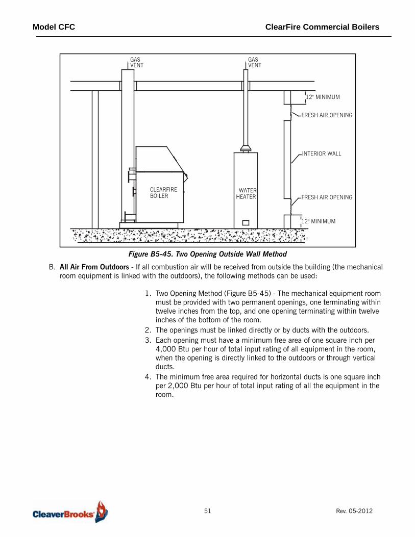
Figure B5-45. Two Opening Outside Wall Method
B. All Air From Outdoors - If all combustion air will be received from outside the building (the mechanicalroom equipment is linked with the outdoors), the following methods can be used:
1. Two Opening Method (Figure B5-45) - The mechanical equipment room must be provided with two permanent openings, one terminating within twelve inches from the top, and one opening terminating within twelve inches of the bottom of the room.
2. The openings must be linked directly or by ducts with the outdoors.3. Each opening must have a minimum free area of one square inch per
4,000 Btu per hour of total input rating of all equipment in the room, when the opening is directly linked to the outdoors or through vertical ducts.
4. The minimum free area required for horizontal ducts is one square inch per 2,000 Btu per hour of total input rating of all the equipment in the room.
GASVENT
CLEARFIREBOILER
WATERHEATER
GASVENT
INTERIOR WALL
FRESH AIR OPENING
FRESH AIR OPENING
12" MINIMUM
12" MINIMUM
51 Rev. 05-2012

Model CFC ClearFire Commercial Boilers
Figure B5-46. Two Opening Ducted Method
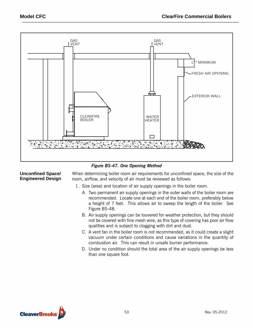
C. One Opening Method (Figure B5-47) - One permanent opening,commencing within 12 inches of the top of the enclosure, shall be provided. 1. The equipment shall have clearances of at least 1 inch from the sides and
back and 6 inches from the front of the appliance.2. The opening shall directly communicate with the outdoors and shall have
a minimum free area of 1 square inch per 3000 BTU's per hour of the total input rating of all equipment located in the enclosure, and not less than the sum of the areas of all vent connectors in the confined space.
3. Refer to the NFGC, Section 8.3 for additional information.
GASVENT
CLEARFIREBOILER
WATERHEATER
GASVENT
EXTERIOR WALL
INTERIOR WALL
FRESH AIRINLET DUCT
OUTLET AIR DUCT
12" MINIMUM
12" MINIMUM
52 Rev. 05-2012
Model CFC ClearFire Commercial Boilers
Figure B5-47. One Opening Method
Unconfined Space/Engineered Design
When determining boiler room air requirements for unconfined space, the size of theroom, airflow, and velocity of air must be reviewed as follows:
1. Size (area) and location of air supply openings in the boiler room.A. Two permanent air supply openings in the outer walls of the boiler room are
recommended. Locate one at each end of the boiler room, preferably belowa height of 7 feet. This allows air to sweep the length of the boiler. SeeFigure B5-48.
B. Air supply openings can be louvered for weather protection, but they shouldnot be covered with fine mesh wire, as this type of covering has poor air flowqualities and is subject to clogging with dirt and dust.
C. A vent fan in the boiler room is not recommended, as it could create a slightvacuum under certain conditions and cause variations in the quantity ofcombustion air. This can result in unsafe burner performance.
D. Under no condition should the total area of the air supply openings be lessthan one square foot.
GASVENT
CLEARFIREBOILER
WATERHEATER
GASVENT
EXTERIOR WALL
FRESH AIR OPENING
12" MINIMUM
53 Rev. 05-2012
Model CFC ClearFire Commercial Boilers
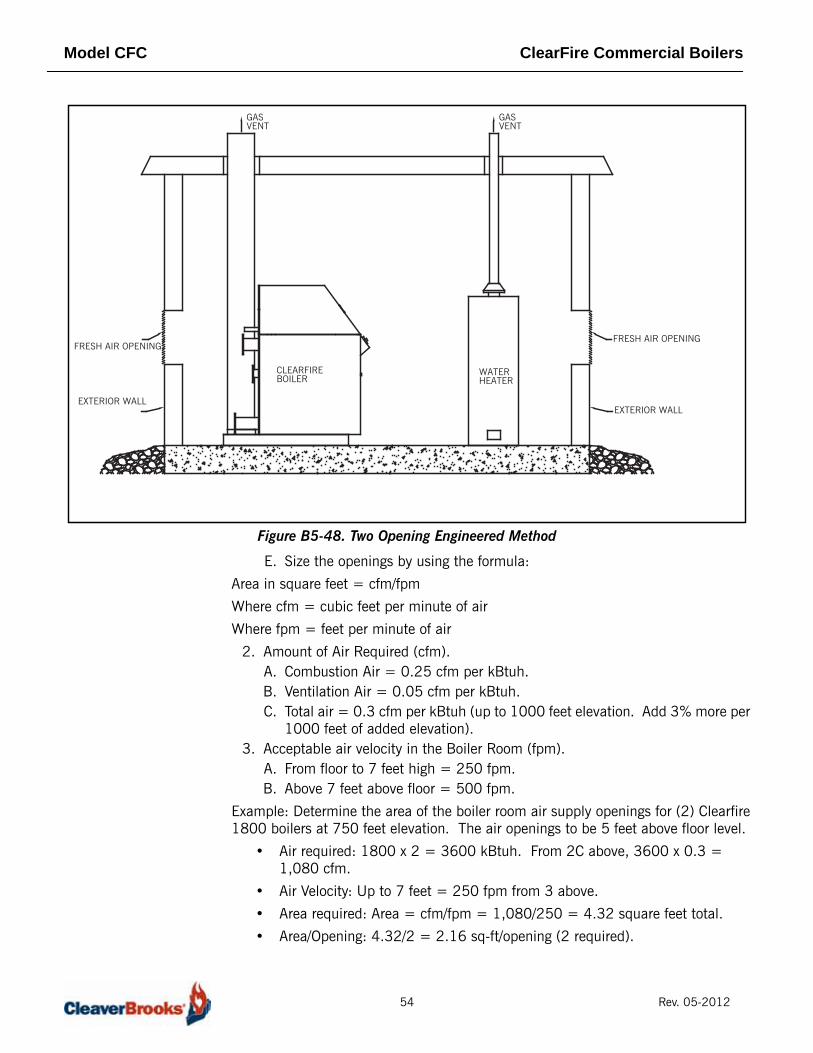
Figure B5-48. Two Opening Engineered Method
E. Size the openings by using the formula:
Area in square feet = cfm/fpm
Where cfm = cubic feet per minute of air
Where fpm = feet per minute of air
2. Amount of Air Required (cfm).A. Combustion Air = 0.25 cfm per kBtuh.B. Ventilation Air = 0.05 cfm per kBtuh. C. Total air = 0.3 cfm per kBtuh (up to 1000 feet elevation. Add 3% more per
1000 feet of added elevation).3. Acceptable air velocity in the Boiler Room (fpm).
A. From floor to 7 feet high = 250 fpm.B. Above 7 feet above floor = 500 fpm.
Example: Determine the area of the boiler room air supply openings for (2) Clearfire1800 boilers at 750 feet elevation. The air openings to be 5 feet above floor level.
• Air required: 1800 x 2 = 3600 kBtuh. From 2C above, 3600 x 0.3 = 1,080 cfm.
• Air Velocity: Up to 7 feet = 250 fpm from 3 above.
• Area required: Area = cfm/fpm = 1,080/250 = 4.32 square feet total.
• Area/Opening: 4.32/2 = 2.16 sq-ft/opening (2 required).
GASVENT
CLEARFIREBOILER
WATERHEATER
GASVENT
EXTERIOR WALL
FRESH AIR OPENING
EXTERIOR WALL
FRESH AIR OPENING
54 Rev. 05-2012

Model CFC ClearFire Commercial Boilers
NoticeConsult local codes, which may supersede these requirements.
Direct Vent Combustion
If combustion air will be drawn directly from the outside by means of a ductconnected to the burner air intake, use the following as a guide:
1. Install combustion air vent (direct vent combustion) in accordance with the boiler's Operating and Maintenance manual.
2. Provide for adequate ventilation of the boiler room or mechanical equipment room.
3. In cold climates, and to mitigate potential freeze-up of the intake pipe, it is highly recommended that a motorized sealed damper be used to prevent the circulation of cold air through the boiler during non-operating hours.
4. Figure B5-49 shows the optional direct vent combustion kit providing easy adaptation of the contractor supplied air duct to boiler connection. Refer to Table B5-26 for sizing the direct vent combustion air pipe.
Figure B5-49. Optional Direct Vent Combustion Kit
STACK/BREECHING SIZE CRITERIAGeneral Boilers are divided into four categories based on the pressure and temperature
produced in the exhaust stack and the likelihood of condensate production in thevent.
• Category I. A boiler which operates with a non-positive vent static pressure and with a vent gas temperature that avoids excessive condensate production in the vent.
• Category II. A boiler which operates with a non-positive vent static pressure and with a vent gas temperature that may cause excessive condensate production in the vent.
• Category III. A boiler which operates with a positive vent pressure and with a vent gas temperature that avoids excessive condensate production in the vent.
• Category IV. A boiler which operates with a positive vent pressure and with a vent gas temperature that may cause excessive condensate production in the vent.
Depending on the application, the Model CFC may be considered Category II, III,or IV. The specifying engineer should dictate flue venting as appropriate to theinstallation.In some cases, PVC/CPVC material meeting ULC Type BH Class IIB specificationsmay be used. Use of PVC/CPVC depends on operating conditions, specific vent
FAN/BLOWER
VENTURI
AIR SUPPLY LINE
55 Rev. 05-2012

Model CFC ClearFire Commercial Boilers
suppliers, and any local codes having jurisdiction. Refer to vent manufacturer’sspecifications for applicability.
Proper installation of flue gas exhaust venting is critical to efficient and safeoperation of the Clearfire Boiler. The vent should be supported to maintain properclearances from combustible materials. Use insulated vent pipe spacers where thevent passes through combustible roofs and walls.
The design of the stack and breeching must provide the required draft at each boilerflue gas connection; proper draft is critical to burner performance.
Although constant pressure at the flue gas outlet is not required, it is necessary tosize the breeching and stack to limit flue gas pressure variation. Consideration ofthe draft must be given whenever direct vent combustion is utilized and lengthy runsof breeching are employed. Please note: The allowable pressure range for design ofthe stack, breeching and if used, direct vent combustion pipe, is negative 0.25"W.C. (- 62 Pa) to positive 0.25" W.C. (+62 Pa) for proper combustion and light offs.
Whenever two or more boilers are connected to a common breeching/stack, a draftcontrol system may be required to ensure proper draft.
Vent Termination To avoid the possibility of property damage or personal injury, special attention tothe location of the vent termination must be considered.
1. Combustion gases can form a white vapor plume in the winter. The plume could obstruct a window view if the termination is installed in close proximity to windows.
2. Prevailing winds could cause freezing of Condensate and water/ice buildup on building, plants, or roof.
3. The bottom of the vent termination and the air intake shall be located at least 12 inches above grade, including the normal snow line.
4. Non-insulated single-wall metal vent pipe shall not be used outside in cold climates for venting combustion gases.
5. Through the wall vents for Category II and Category IV appliances shall not terminate over public walkways or over an area where Condensate or vapor could create a nuisance or hazard or could be detrimental to the operation of other equipment.
6. To prevent accidental contact by people or pets, the vent termination shall be guarded.
7. DO NOT terminate vent in window well, alcove, stairwell or other recessed area, unless approved by local authority.
8. DO NOT terminate above any door, window, or gravity air intake as Condensate can freeze causing ice formation.
9. Locate or guard vent to prevent Condensate from damaging exterior finishes. Use a 2' x 2' rust resistant sheet metal backing plate against brick or masonry surfaces.
10. Multiple direct stack installations require four feet clearance between the stack caps, center to center.
U.S. Installations Refer to the latest edition of the National Fuel Gas Code/NFPA 54. Vent termination requirements are:
1. Vent must terminate at least four feet below and four feet horizontally or one foot above any door, window or gravity air inlet to the building.
56 Rev. 05-2012

Model CFC ClearFire Commercial Boilers
2. The vent must be at least seven feet above grade when located adjacent to public walkways.
3. Terminate vent at least three feet above any forced air inlet located within ten feet.
4. Vent must terminate at least four feet horizontally, and in no case above or below unless four feet horizontal distance is maintained, from electric meters, gas meters, regulators, and relief equipment.
5. Terminate vent at least six feet from adjacent walls.6. DO NOT terminate vent closer than five feet below roof overhang.
Canadian Installations
Refer to the latest edition of CAN/CSA-B149.1 and B149.2. Vent shall not terminate:
1. Directly above a paved sidewalk or driveway which is located between two single-family dwellings and serves both dwellings.
2. Less than 7 feet (2.31m) above a paved sidewalk or paved driveway located on public property.
3. Within 6 feet (1.8m) of a mechanical air supply inlet to any building.4. Above a meter/regulator assembly with 3 feet (900mm) horizontally of the
vertical centerline of the regulator.5. Within 6 feet (1.8m) of any gas service regulator vent outlet.6. Less than 1 foot (300mm) above grade level.7. Within 3 feet (1m) of a window or door which can be opened in any building,
any non-mechanical air supply inlet to any building or to the combustion air inlet of any other appliance.
8. Underneath a Verandah, porch, or deck unless:A. The Verandah, porch, or deck is fully open on a minimum of two sides
beneath the floor.B. The distance between the top of the vent termination and the underside of
the Verandah, porch, or deck is greater than one foot (300mm).
Horizontal Through the Wall Venting
Venting configurations using inside air for combustion (See Figure B5-50) These installations utilize the boiler-mounted blower to vent the combustionproducts to the outside. Combustion air is obtained from inside the room and theexhaust vent is installed horizontally through the wall to the exterior of the building.Adequate combustion and ventilation air must be supplied to the boiler room inaccordance with the NFGC/NFPA 54 for the U.S. and in Canada, the latest editionof CAN/CSA-B149.1 and.2 Installation Code for Gas Burning Appliances andEquipment.
57 Rev. 05-2012

Model CFC ClearFire Commercial Boilers
Figure B5-50. Horizontal Through the wall venting using inside air for combustion
The vent must be installed to prevent the potential accumulation of stackcondensate in the horizontal run of vent pipe. Therefore, it is recommended that:
1. The vent shall be installed with a slight downward slope of not more than 1/4" per foot of horizontal run to the vent termination.
2. The vent must be insulated through the length of the horizontal run.
Note: For installations in cold/freezing climates, it is recommended that:
1. The vent shall be installed with a slight upward slope of not more than 1/4" per foot of horizontal run to the vent termination. In this case, an approved Condensate trap must be installed per applicable codes.
2. The vent must be insulated through the length of horizontal run.
The stack vent cap MUST be mounted on the exterior of the building. The stack ventcap cannot be installed in a well or below grade. The stack vent cap must beinstalled at least two feet above ground level and above normal snow levels.
NoticeThe stainless steel direct vent cap must be furnished in accordance with AGA/CGA requirements.
Refer to Table B5-25 for the recommended sizes of horizontal vent pipe.
Horizontal Through the Wall Stack Venting
Direct Vent Combustion. See Figure B5-51.
12" Minimum + any
Flue Gas Vent
Inside AirCombustion
Intake
(w/Screen)
Snow Load
58 Rev. 05-2012
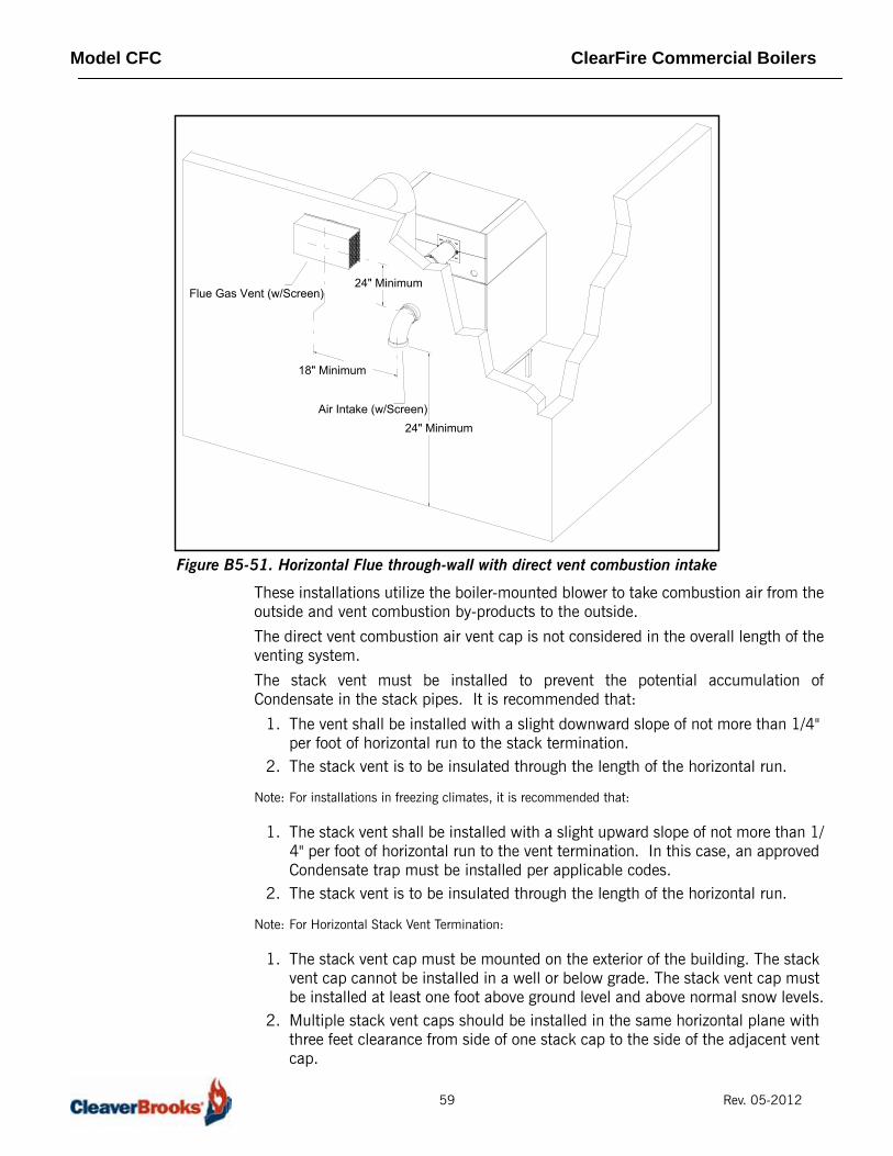
Model CFC ClearFire Commercial Boilers
Figure B5-51. Horizontal Flue through-wall with direct vent combustion intake
These installations utilize the boiler-mounted blower to take combustion air from theoutside and vent combustion by-products to the outside.
The direct vent combustion air vent cap is not considered in the overall length of theventing system.
The stack vent must be installed to prevent the potential accumulation ofCondensate in the stack pipes. It is recommended that:
1. The vent shall be installed with a slight downward slope of not more than 1/4" per foot of horizontal run to the stack termination.
2. The stack vent is to be insulated through the length of the horizontal run.
Note: For installations in freezing climates, it is recommended that:
1. The stack vent shall be installed with a slight upward slope of not more than 1/4" per foot of horizontal run to the vent termination. In this case, an approved Condensate trap must be installed per applicable codes.
2. The stack vent is to be insulated through the length of the horizontal run.
Note: For Horizontal Stack Vent Termination:
1. The stack vent cap must be mounted on the exterior of the building. The stack vent cap cannot be installed in a well or below grade. The stack vent cap must be installed at least one foot above ground level and above normal snow levels.
2. Multiple stack vent caps should be installed in the same horizontal plane with three feet clearance from side of one stack cap to the side of the adjacent vent cap.
18" Minimum
24" Minimum
24" Minimum
Air Intake (w/Screen)
Flue Gas Vent (w/Screen)
59 Rev. 05-2012

Model CFC ClearFire Commercial Boilers
3. Combustion air supplied from the outside must be free of particulate and chemical contaminants. To avoid a blocked flue condition, keep all the vent caps clear of snow, ice, leaves, debris, etc.
Note: Multiple direct stack vent caps must not be installed with one combustion air inlet directly above a stack vent cap. This vertical spacing would allow the flue products from the stack vent to be pulled into the combustion air intake installed above. This type of installation can cause non-warrantable problems with components and poor operation of the unit due to the recirculation of flue products.
Table B5-25. STACK DESIGN (SINGLE BOILER) USING ROOM AIR
ROOM COMBUSTION AIR -- MAXIMUM ALLOWABLE VENTING LENGTH
BoilerBoiler Stack/Flue
ConnectionBoiler
Flue/StackSize
Maximum length of Flue Gas Vent in
Feet*
Flue Connection Part No.
RoomCombustion Air Required (CFM)
Air Filter Kit No. (optional)
CFC 500 6" Standard 6" 80 039-01704 125 880-01858
CFC 750 6" Standard 6" 60 039-01704 190 880-01858
CFC1000 6" Option 6" 80 039-01646 250 880-01858
CFC1000 8" Standard 8" 140 039-01647 250 880-01858
CFC1000 10" Option 10" 200 039-01705 250 880-01858
CFC1500 8" Option 8" 60 039-01645 375 880-02005
CFC1500 10" Standard 10" 80 039-01644 375 880-02005
CFC1500 12" Option 12" 120 039-01688 375 880-02005
CFC1800 10" Option 10" 60 039-01644 450 880-02005
CFC1800 12" Standard 12" 100 039-01688 450 880-02005
CFC 2500 12" Standard 12" 110 039-01688 625 880-02005
CFC3300 12" Standard 12" 60 039-01761 800 880-02502
CFC3300 14" Option 14" 110 039-01762 800 880-02502
* Each additional 90 elbow equals 5 equivalent feet of ductwork. Flue terminations may add 5-10 feet to the equivalent length and should also be included in the equivalent length calculation.** Increasing the diameter of the air intake will reduce the overall pressure drop and thereby allowlonger total vent lengths.
Draft tolerance at boiler flue connection during operation is +/- 0.25” WC.
60 Rev. 05-2012
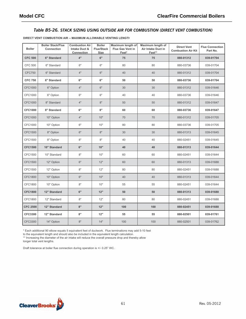
Model CFC ClearFire Commercial Boilers
Table B5-26. STACK SIZING USING OUTSIDE AIR FOR COMBUSTION (DIRECT VENT COMBUSTION)
DIRECT VENT COMBUSTION AIR -- MAXIMUM ALLOWABLE VENTING LENGTH
BoilerBoiler Stack/Flue
ConnectionCombustion Air Intake Duct & Connection
BoilerFlue/Stack
Size
Maximum length of Flue Gas Vent in
Feet*
Maximum length of Air Intake Duct in
Feet**
Direct Vent Combustion Air Kit
Flue Connection Part No.
CFC 500 6" Standard 4" 6" 75 75 880-01312 039-01704
CFC 500 6" Standard 6" 6" 80 80 880-03736 039-01704
CFC750 6" Standard 4" 6" 40 40 880-01312 039-01704
CFC 750 6" Standard 6" 6" 50 50 880-03736 039-01704
CFC1000 6" Option 4" 6" 30 30 880-01312 039-01646
CFC1000 6" Option 6" 6" 40 40 880-03736 039-01646
CFC1000 8" Standard 4" 8" 50 50 880-01312 039-01647
CFC1000 8" Standard 6" 8" 60 60 880-03736 039-01647
CFC1000 10" Option 4" 10" 70 70 880-01312 039-01705
CFC1000 10" Option 6" 10" 80 80 880-03736 039-01705
CFC1500 8" Option 6" 8" 30 30 880-01313 039-01645
CFC1500 8" Option 8" 8" 40 40 880-02451 039-01645
CFC1500 10" Standard 6" 10" 40 40 880-01313 039-01644
CFC1500 10" Standard 8" 10" 60 60 880-02451 039-01644
CFC1500 12" Option 6" 12" 60 60 880-01313 039-01688
CFC1500 12" Option 8" 12" 80 80 880-02451 039-01688
CFC1800 10" Option 6" 10" 40 40 880-01313 039-01644
CFC1800 10" Option 8" 10" 55 55 880-02451 039-01644
CFC1800 12" Standard 6" 12" 50 50 880-01313 039-01688
CFC1800 12" Standard 8" 12" 80 80 880-02451 039-01688
CFC 2500 12" Standard 8" 12" 100 100 880-02451 039-01688
CFC3300 12" Standard 8" 12" 55 55 880-02501 039-01761
CFC3300 14" Option 8" 14" 100 100 880-02501 039-01762
* Each additional 90 elbow equals 5 equivalent feet of ductwork. Flue terminations may add 5-10 feet to the equivalent length and should also be included in the equivalent length calculation.** Increasing the diameter of the air intake will reduce the overall pressure drop and thereby allowlonger total vent lengths.
Draft tolerance at boiler flue connection during operation is +/- 0.25” WC.
61 Rev. 05-2012

Model CFC ClearFire Commercial Boilers
Vertical Venting Inside Combustion Air
See Figure B5-52.
Figure B5-52. Inside Air - Vertical Vent
As noted in Paragraph A above, these installations use air from within the boilerroom for combustion. The same recommendations apply as noted in Paragraph Aabove and also, the recommendations on flue vent sizing according to Table B5-25.
CFC Boiler
Flue Gas Vent
24"Minimum
10'-0" or Less
48"Minimum
Termination
62 Rev. 05-2012

Model CFC ClearFire Commercial Boilers
Vertical Venting Direct Vent Combustion
See Figure B5-53.
Figure B5-53. Vertical Stack with Direct Vent Combustion Air
As noted in Paragraph B above, these installations use air from outside the buildingfor combustion. The same recommendations apply as noted in B and also, therecommendations on flue vent sizing according to Table B5-26.
ELECTRICAL Voltage requirements for the Fan Motor are 115 - 120/1/60. Control Circuit voltageis 120/1/60 for all boiler sizes. Refer to Table B5-3 "Ratings" for ampacityrequirements.
Refer to Figure B5-54 through Figure B5-56 for wiring connections and controllocations.
Boiler
Vent TerminationAir Intake (w/Screen)
48" Minimum48" Minimum
12" Minimumabove roofor snow line
Boiler
Vent Termination
Air Intake (w/Screen)
48" Minimum
12" Minimumabove parapetor snow line
36" Minimumabove intak
24" Minimum
With parapet wall
63 Rev. 05-2012

Model CFC ClearFire Commercial Boilers
Figure B5-54. Electrical Connections CFC 500-2500
64 Rev. 05-2012
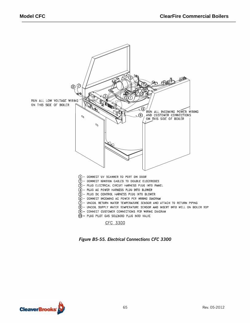
Model CFC ClearFire Commercial Boilers
Figure B5-55. Electrical Connections CFC 3300
65 Rev. 05-2012

Model CFC ClearFire Commercial Boilers
Figure B5-56. CFC Rear Connections
66 Rev. 05-2012
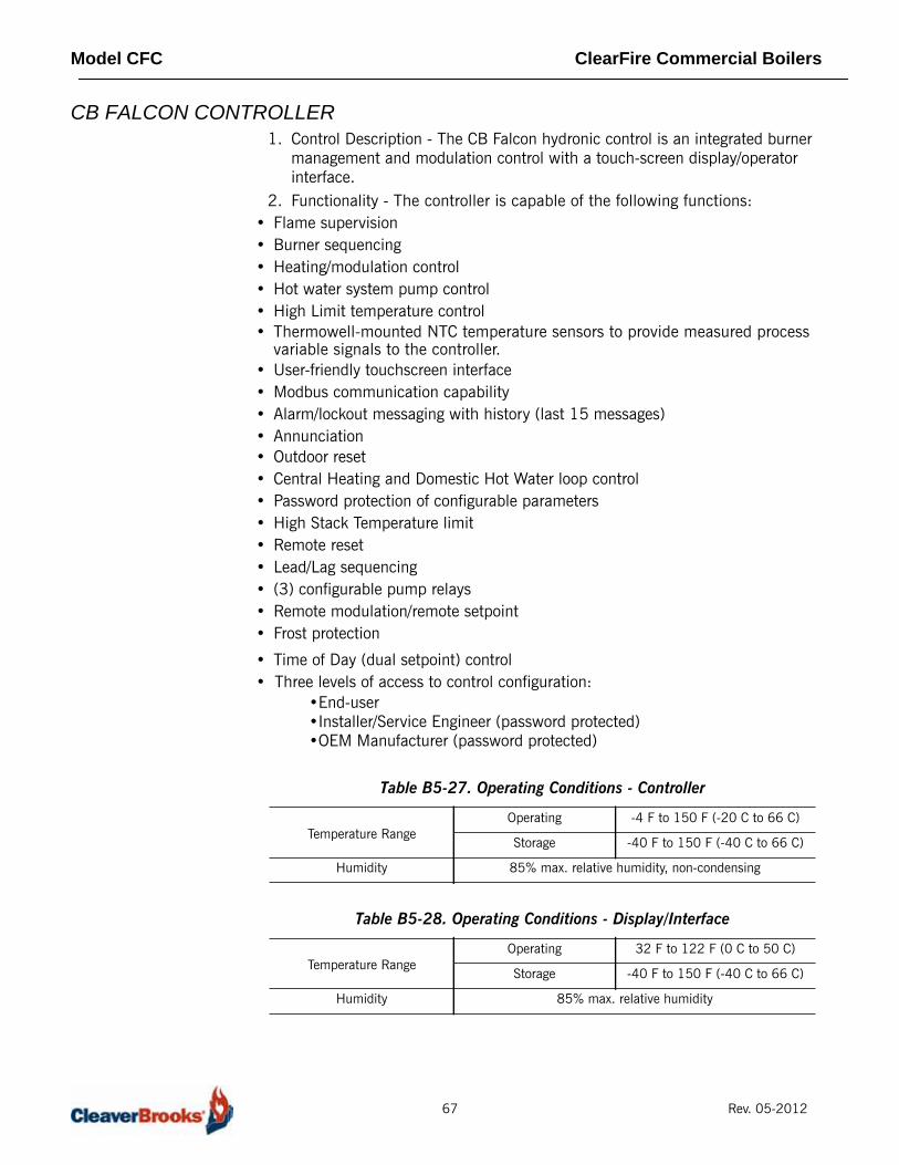
Model CFC ClearFire Commercial Boilers
CB FALCON CONTROLLER1. Control Description - The CB Falcon hydronic control is an integrated burner
management and modulation control with a touch-screen display/operator interface.
2. Functionality - The controller is capable of the following functions:• Flame supervision• Burner sequencing• Heating/modulation control• Hot water system pump control• High Limit temperature control• Thermowell-mounted NTC temperature sensors to provide measured process
variable signals to the controller.• User-friendly touchscreen interface• Modbus communication capability• Alarm/lockout messaging with history (last 15 messages)• Annunciation• Outdoor reset• Central Heating and Domestic Hot Water loop control• Password protection of configurable parameters• High Stack Temperature limit• Remote reset• Lead/Lag sequencing• (3) configurable pump relays• Remote modulation/remote setpoint• Frost protection
• Time of Day (dual setpoint) control• Three levels of access to control configuration:
•End-user•Installer/Service Engineer (password protected)•OEM Manufacturer (password protected)
Table B5-27. Operating Conditions - Controller
Temperature RangeOperating -4 F to 150 F (-20 C to 66 C)
Storage -40 F to 150 F (-40 C to 66 C)
Humidity 85% max. relative humidity, non-condensing
Table B5-28. Operating Conditions - Display/Interface
Temperature RangeOperating 32 F to 122 F (0 C to 50 C)
Storage -40 F to 150 F (-40 C to 66 C)
Humidity 85% max. relative humidity
67 Rev. 05-2012

Model CFC ClearFire Commercial Boilers
3. Main Voltage Connection - 115V/single phase/60Hz4. Local/Remote demand switch5. Combustion Air Proving Switch - This input is used for proving airflow sufficient
for proper combustion throughout the burner run sequence.6. High Air Pressure Switch - prevents boiler operation in the event of high stack
back pressure (blocked flue or condensate drain).7. Gas Pressure Switch - Gas pressure switches for low gas pressure and high gas
pressure prevent the burner from being activated if either is open. Each switch is a physical manual reset device, requiring physical depression of the reset button if either switch is not closed prior to burner start or during burner operation.
8. NTC (Negative Temperature Coefficient) Thermistor Inputs (10k @ 25 oC)A.Flow Temperature (Outlet water temperature)B.Return Temperature (Inlet water temperature)C.Optional Domestic Water TemperatureD.Optional Outdoor TemperatureE.Optional Stack TemperatureF.Optional Header Temperature
9. System Configuration - CB Falcon configuration is arranged into the following functional groups:
Table B5-29. CB Falcon burner sequence (Central Heat)
1. Heat request detected (CH demand)
2. CH pump switched on
3. Safe Start Check, dynamic ILK input test (if enabled), blower switched on
4. If ILK input and CAPS switch closed and purge rate fan speed achieved, begin 15 second prepurge
5. When purge complete, blower RPM changed to lightoff speed
6. Trial for Ignition - 4 seconds*
7. Ignition and gas valve switched on*
8. Ignition turned off at the end of direct ignition period; 5 sec. stabilization time*
9. Release to modulation (Run)
10. At the end of CH heat request, burner is switched off and blower stays on for 15 sec. post purge period. Boiler enters standby mode.
*CFC 3300 uses pilot ignition - lightoff sequence will vary accordingly
System Identification andAccesss
CH - Central Heat
Outdoor Reset
DHW - Domestic Hot Water
DHW Storage
DHW Plate
Warm Weather Shutdown
Demand Priority
Modulation Configuration
Pump Configuration
Statistics Configuration
High Limit
Stack Limit
Delta T Limits
T-Rise Limit
Heat Exchanger High Limit
Anti-condensation
Frost Protection Configuration
Annunciation Configuration
Burner Control Interlocks
68 Rev. 05-2012
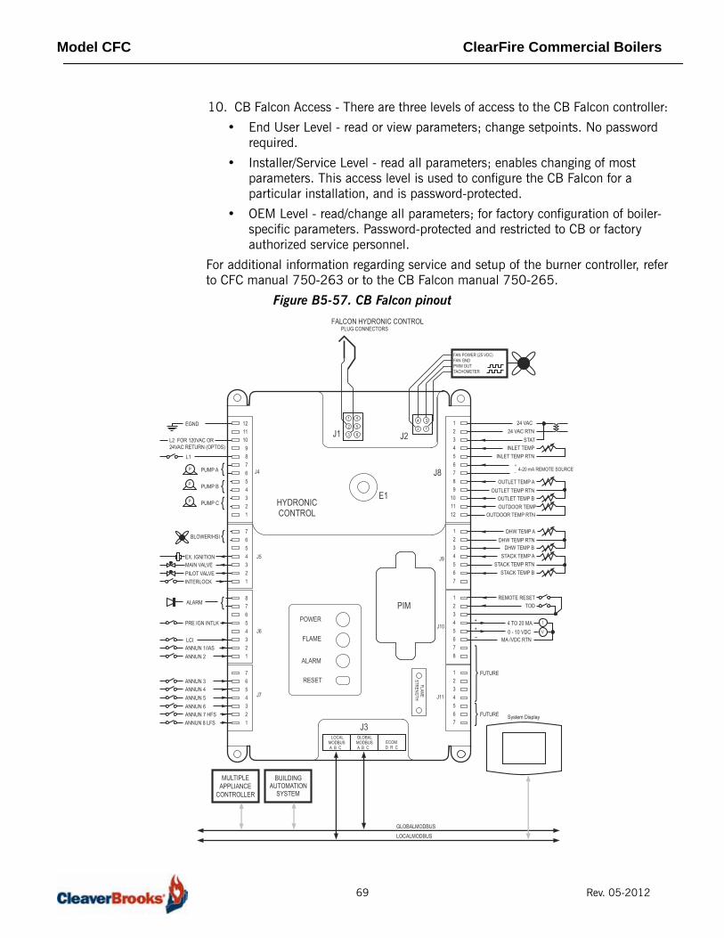
Model CFC ClearFire Commercial Boilers
10. CB Falcon Access - There are three levels of access to the CB Falcon controller:
• End User Level - read or view parameters; change setpoints. No password required.
• Installer/Service Level - read all parameters; enables changing of most parameters. This access level is used to configure the CB Falcon for a particular installation, and is password-protected.
• OEM Level - read/change all parameters; for factory configuration of boiler-specific parameters. Password-protected and restricted to CB or factory authorized service personnel.
For additional information regarding service and setup of the burner controller, referto CFC manual 750-263 or to the CB Falcon manual 750-265.
Figure B5-57. CB Falcon pinout
3
1
4
2
FLAMESTRENGTH
LOCALMODBUSA B C
GLOBALMODBUSA B C
POWER
FLAME
ALARM
RESET
PIM
1
2
3
4
5
6
HYDRONICCONTROL
J1 J2
J3ECOMD R C
L1
L2 FOR 120VAC OR 24VAC RETURN (OPTOS)
EGND
BLOWER/HSI
EX. IGNITION
ALARM
MAIN VALVEPILOT VALVE
ANNUN 1/IASANNUN 2
ANNUN 3ANNUN 4ANNUN 5ANNUN 6
PRE IGN INTLK
INTERLOCK
P
P
P
LCI
PUMP A
{{
{
{
PUMP B
PUMP C
ANNUN 7 HFSANNUN 8 LFS
24 VAC24 VAC RTN
INLET TEMPINLET TEMP RTN
4-20 mA REMOTE SOURCE
OUTLET TEMP AOUTLET TEMP RTN
OUTLET TEMP BOUTDOOR TEMP
OUTDOOR TEMP RTN
DHW TEMP ADHW TEMP RTN
DHW TEMP BSTACK TEMP A
STACK TEMP RTNSTACK TEMP B
TODREMOTE RESET
0 - 10 VDC MA /VDC RTN
4 TO 20 MAV
I
BUILDINGAUTOMATION
SYSTEM
FUTURE System Display
TACHOMETERPWM OUT
FAN POWER (25 VDC)FAN GND
MULTIPLEAPPLIANCE
CONTROLLER
GLOBALMODBUSLOCALMODBUS
++–
FUTURE
STAT
FALCON HYDRONIC CONTROLPLUG CONNECTORS
J4
J5
J6
J7
J8
J9
J10
J11
121110 9 8 7 6 5 4 3 2 1
7654321
87654321
7654321
123456789
101112
1234567
12345678
1234567
+_
E1
69 Rev. 05-2012

Model CFC ClearFire Commercial Boilers
70 Rev. 05-2012