model 9430 flexible matrix router 3g/hd/sd/asi/310m€¦ · model 9430 flexible matrix router...
TRANSCRIPT

Model 9430 Flexible Matrix Router 3G/HD/SD/ASI/310M
Installation, Configuration and Operations Guide
Revision 1.2 SW v1.1.2

By Engineers, For Engineers
In 1989, a former television station engineer who loved designing and building video equipment, decided to start a new company. He relished the idea of taking an existing group of equipment and adding a few special pieces in order to create an even more elegant ensemble. So, he designed and built his first product and the company was born.
Focused On What You Need
As the company has grown, more former TV station engineers have joined Ensemble Designs and this wealth of practical experience fuels the company’s innovation. Everyone at the company is focused on providing the very equipment you need to complete your ensemble of video and audio gear. We offer those special pieces that tie everything together so that when combined, the whole ensemble is exactly what you need.
Notably Great Service for You
We listen to you – just tell us what you need and we’ll do our best to build it. We are completely focused on you and the equipment you need. Being privately held means we don’t have to worry about a big board of directors or anything else that might take attention away from real business. And, you can be sure that when you call a real person will answer the phone. We love this business and we’re here to stay.
Bricks and Mortar of Your Facility
The bricks and mortar of a facility include pieces like up/downconverters, audio embedders, video converters, routers, protection switches and SPGs for SD, HD and 3Gb/s. That’s what we’re focused on, that’s all we do – we make proven and reliable signal processing and infrastructure gear for broadcasters worldwide, for you.
Who is Ensemble Designs?
Avenue frames handle 270 Mb/s, 1.5 Gb/s and 3 Gb/s signals, audio and MPEG signals. Used worldwide in broadcast, mobile, production, and post.
We’re focused on processing gear– 3G/HD/SD/ASI video, audio and optical modules.
Come on by and visit us. Drop in for lunch and a tour!
Shipped with care to television broadcasters and video facilities all over the world.
Clearly, Ensemble wants to be in the broadcast equipment business. It’s so rare anymore to find a company of this caliber that has not been gobbled up by a large corporation. They are privately held so they don’t have to please the money people. They really put their efforts into building products and working with customers.
I’m really happy with the Avenue products and Ensemble’s service, and even more important my engineers are happy. We’ve continued to upgrade the product and add more cards. We will be rebuilding our production control room and we will use Avenue again. ~ Don McKay, Vice President Engineering, Oregon Public Broadcasting

www.ensembledesigns.com Page 3
Avenue 9430 Flexible Matrix Router Installation, Configuration and Operations Guide
Contents
Preface 11
Document Organization at a Glance 11
Chapter 1: Introduction 13
In this Chapter 13
Purpose of Document 13
Intended Audience 13
Introductory Video from David Wood, Chief Design Engineer 14
Additional Resources 14
Chapter 2: System Overview 15
In this Chapter 15
Hardware Elements 15
9430 Router Module 16
Built-in Signal Diagnostics 16
Fail-Safe Relay Bypass Mechanism 16
9440 I/O Expansion Module Option 16
9435 Dual Clean Switch Submodule Option 16
5830 Router Control Panel 16
Long Distance Capability 17
Applications 17
Cuts-Only Master Control 17
Master Control Bypass 17
Quality Control and Signal Monitoring 18
Monitors and Projectors for Venues 18
Example Diagram of Complete Router System with All Options Installed 19
Router Expansion Example for a 21 In x 9 Out Router Configuration 20
Example Diagram of Router System Using One 9430, One 9440 and One 9435 21
www.ensembledesigns.com Page 4
Avenue 9430 Flexible Matrix Router Installation, Configuration and Operations Guide
Chapter 3: Installation 22
In this Chapter 22
PART ONE: MODULE ASSEMBLY 23
Original Orders Preassembled 23
9430 Router Module 23
9435 Dual Clean Switch Option 24
9430 and 9435 Fit in a Single Frame Slot 25
9440 I/O Expansion Option 26
Two Types of Routing Backplane Kits 26
Sliding Routing Backplanes through Slots in the 9430 27
Installing Stand-Offs on the 9440 28
Aligning the 9440 with Routing Backplanes 28
Example of Completed Assembly 29
PART TWO: REQUIRED CABLE CONNECTIONS 29
Seating the Board Set Firmly in the Frame 29
Avenue 3RU Frame Partition Divider Consideration 29
Installing the BNC Plastic Overlays 30
Digital Signal Connections 31
Cable Length Considerations 31
Fail-Safe Bypass from Input 1 to Output 1 31
Router Control Connections 32
RS-232 and 100Mb Ethernet Interface Adaptor Cable 32
Connecting a Timing Reference to the Avenue Frame 33
Connecting a Timing Reference to the 9430 Router 33
Router Control Panel Installation 34
Connecting Ethernet Cable to RJ-45 Port 34
Long Distance Capability 34
Labeling Buttons 35
First Method: Key Cap Inserts 35
Second Method: Customizable Label Template 36
GPI Control 38

www.ensembledesigns.com Page 5
Avenue 9430 Flexible Matrix Router Installation, Configuration and Operations Guide
Chapter 4: Configuration 39
In this Chapter 39
The Router's Network Environment 39
Avenue Touch Screen and Avenue PC Controls 39
Initially Connecting to the Router 40
Establishing Network Connectivity between Controlling Computer and 9430 40
Assigning the Router a New IP Address and Subnet Mask 40
Method One: For Customers Using Avenue Touch Screen or Avenue PC 40
To Set the IP Address 40
To Set the Subnet Mask 41
Method Two: For Customers Not Using Avenue Touch Screen or Avenue PC 42
Temporarily Changing IP Address on Controlling Computer 42
Consideration 42
Instructions for Temporarily Changing the IP Address for Mac and Windows XP 42
To Set the IP Address on the 9430 Router 46
Readjusting Controlling Computer’s IP Address to be in Range of Router’s Newly Assigned IP Address 48
Establishing Initial Control Point and Profile for Administrator Functions 49
To Create an Initial Control Point 49
To Assign the Factory Default Profile to the Router Admin Control Point 51
Security and Administrative Access to Settings 53
To Limit Access to the Router’s Settings 53
Configuring the Router's Ports 54
Planning Router Port Configuration 54
Cabling Router to Match Plan 54
Components Chosen Determines Quantity and Types of Ports Available 54
One 9430 Module 54
One 9430 Module and One 9440 Module 54
One 9430 Module and Two 9440 Modules 54
Definitions of Port Configuration Choices 55
Unassigned 55
Source 55
Destination 55
www.ensembledesigns.com Page 6
Avenue 9430 Flexible Matrix Router Installation, Configuration and Operations Guide
Follow 55
Paired 55
Primary TSG 55
Secondary TSG 56
Port Configuration Choices Available According to Port Type 56
For Fixed Input 56
For Fixed Output 56
For Bi-Directional 56
Implementing Router Port Configuration Plan 57
To Configure the Router’s Ports 57
Creating and Editing Profiles 59
Characteristics of Profiles 59
Creating an Initial Set of Profiles 59
To Create a Profile 59
Examples of Profiles 60
Master Control Room (MCR) 10 x 3 60
MCR Profile Edited and Reordered to 8 x 3 61
MCR Profile Edited to 8 x 1 62
Establishing Control Points and Access Authentication 63
Characteristics of Control Points 63
Examples of Control Points 64
Configuring the 5830 Router Control Panel 64
Assigning an IP Address to the 1RU Control Panel 64
Creating a Control Point for the 5830 Panel 67
Configuring Other Control Points 68
First Method: Requesting Access from a Control Point 68
Second Method: Assigning an IP Address as a Control Point 68
Approving Pending Authorizations 68
Number of Control Points That Can Operate Simultaneously 69
Asymmetrical Bandwidth Requirements 69
Best Practice: Closing Web Browser Control Points When Not In Use 69
Setting Up Timing and Genlock 70
System Frame Rate 70
Vertical Interval Switch Point 70
www.ensembledesigns.com Page 7
Avenue 9430 Flexible Matrix Router Installation, Configuration and Operations Guide
Note on Frame Rates 71
50 Hz 71
59.94 Hz 71
60 Hz 71
Configuring Internal Test Signal Generators 72
Test Signal Generator Configuration 72
Standard 74
Pattern 74
Switch Mark 74
Vertical and Horizontal Timing 75
Audio Embedding 75
Audio Reference Level 76
Audio Group Enable 76
Audio Source Selection 76
Slate Enable 77
Slate Text 77
Cyclops 77
Switch Point Identification 78
Working with the Clean Switch Option 80
Clean Switch Configuration 83
Assign To 84
Standard 84
Non Standard Blocking 84
Vertical and Horizontal Timing 85
Audio Embed 86
Chapter 5: Operations and Step-by-Step Procedures 87
In this Chapter 87
Router Control Panel (5830) Operation 87
Orientation of Front Panel 87
Performing Takes with the Router Control Panel 87
To Perform a Take by Selecting a Source and a Destination 87
To Perform a Take by Selecting Only a New Source 88
Performing Direct Takes with the Router Control Panel 88
To Perform a Direct Take 88
www.ensembledesigns.com Page 8
Avenue 9430 Flexible Matrix Router Installation, Configuration and Operations Guide
To Exit Direct Take Mode 88
Accessing Ancillary Data with the Router Control Panel 88
To Access Ancillary Data 88
Router Operation with the Web Browser Interface 89
Prerequisites 89
Accessing the Web Browser Control Interface 89
About the Web Browser Interface 90
Preferences 91
Message Bar 92
Performing Takes with a Web Browser 93
To Perform a Take by Selecting a Source and a Destination 93
To Perform a Take by Selecting Only a New Source 93
Performing Direct Takes with a Web Browser 94
To Perform a Direct Take 94
To Exit Direct Take Mode 94
Performing Gang Takes with a Web Browser 95
To Perform a Gang Take 95
To Exit Gang Mode 95
Performing Direct Gang Takes with a Web Browser 95
To Perform a Direct Gang Take 95
To Exit Direct Gang Mode 95
Chapter 6: External Control 96
The Router’s Approach to Control Integration 96
RS-232 Interface and 9-Pin D Connector Pin Out 96
Router Control Panel (5830) GPI Inputs 96
Overview of Supported Control Protocols 96
Avenue FMR 97
Simultaneous Support for Multiple Protocols 97
Control Profiles for External Interfaces 97
Grass Valley TenXL 97
Grass Valley 100 97
Generic ASCII 97
RS-232 97

www.ensembledesigns.com Page 9
Avenue 9430 Flexible Matrix Router Installation, Configuration and Operations Guide
Telnet 97
TCP/IP 98
Additional GPI and Serial Connections through JL Cooper eBOX 98
SNMP Interface 98
Programming Reference Document 98
Software Development Kit (SDK) 98
Accessing Features Unique to the 9430 Flexible Matrix Router 98
Configuring External Control 99
Chapter 7: Maintenance and Troubleshooting 100
Troubleshooting the Router Module (9430) 100
Cannot Connect to the Router 100
Router Not Running 100
To Determine if the Router is Running 100
Resetting the Router 100
Rebooting 100
Resetting to Factory Default Settings 100
Authorized Control Point Unable to Connect to Router 100
Troubleshooting the Router Control Panel (5830) 101
Router Control Panel has Lost its Connection to the Router 101
Rebooting the Router Control Panel 101
Resetting the Router Control Panel to Factory Default Settings 101
Configuration Changes are not Taking Effect 101
Troubleshooting the Web Browser Control UI 101
If the Take Button is Grayed Out 101
Supported Browsers 101
Software Updating 102
Warranty and Factory Service 102
Specifications 103
9430 103
9440 104

www.ensembledesigns.com Page 10
Avenue 9430 Flexible Matrix Router Installation, Configuration and Operations Guide
Appendix A: Automation Protocols 105
1 Introduction 105
2 Conventions 105
3 Overview 106
4 Before You Begin 106
5 Understanding Profiles 107
6 Configuration 109
6.1 Profile Configuration 110
6.2 External Control Configuration 110
6.2.1 Connection Mode 110
6.2.2 Protocol Selection 112
6.2.3 Profile Selection 112
7 Protocols 112
7.1 GV TEN-XL ASCII Protocol 112
7.1.1 Protocol Requirements 113
7.1.2 Commands 113
7.2 GV Performer ASCII Protocol 116
7.2.1 Protocol Requirements 116
7.2.2 Message Structure 117
7.2.3 Commands 117
7.3 Generic ASCII Protocol 121
7.3.1 Protocol Requirements 121
7.3.2 Router Responses 122
7.3.3 Commands 123
Glossary 129

www.ensembledesigns.com Page 11
Avenue 9430 Flexible Matrix Router Installation, Configuration and Operations Guide
PrefaceDocument Organization at a GlanceThis manual addresses all of the essential topics for understanding how to install, configure and use the Router Module (9430) and its optional components—the Dual Clean Switch Submodule Option (9435), the I/O Expansion Module Option (9440), and the Router Control Panel (5830). See the following table for a quick glance at what each chapter addresses. Note also that all of the items in the main table of contents, as well as the chapter titles below, are links.
Chapter Title Topics Covered
Chapter 1: Introduction A brief introduction to this document and to the Router. Includes a link to a short video by David Wood, Chief Design Engineer.
Chapter 2: System Overview
Describes the overall Router system—its hardware and software components, example applications, and diagrams of example configurations.
Chapter 3: Installation This chapter consists of two parts:
Part One describes how components are assembled in the event that you need to add components in the future. Original orders are delivered preassembled.
Part Two describes required cable connections that all customers must perform, as well as Router Control Panel (5830) installation.
Chapter 4: Configuration Covers initially connecting to the Router, port configuration, creating and editing profiles, control points and access authentication, timing and genlock, internal test signal generators, switch point identification, and working with the clean switch option.
Chapter 5: Operations and Step-by-Step Procedures
After the Router has been installed and configured, it is ready to use. This chapter addresses all of the standard operational tasks of the Router that you can perform using the Router Control Panel (5830) and web browser interface. Operational tasks include performing takes, direct takes, gang takes, direct gang takes, and accessing ancillary data.
Chapter 6: External Control Provides an overview of how the Router handles external control integration; the Router Control Panel GPI Inputs; supported control protocols, including Ensemble Designs’ unique Avenue FMR protocol that supports multiple simultaneous protocols and control profiles for external interfaces.
Chapter 7: Maintenance and Troubleshooting
This chapter addresses certain known issues and possible issues that new users may encounter while becoming familiar with using the Flexible Matrix Router.
Specifications Presents standard specifications for the 9430 regarding inputs, max cable length, outputs and reference. Specifications for the inputs and outputs are also covered for the 9440.

www.ensembledesigns.com Page 12
Avenue 9430 Flexible Matrix Router Installation, Configuration and Operations Guide
Chapter Title Topics Covered
Appendix A: Automation Protocols
This appendix describes the various communication protocols available in the 9430 Flexible Matrix Router to support external control by an automation system. It also discusses the various means for connecting an external controller to the router. The intended audience is the developer tasked with connecting an external control device to the router.
Glossary Includes definitions of commonly-used terms relevant to the video broadcast industry.
www.ensembledesigns.com Page 13
Avenue 9430 Flexible Matrix Router Installation, Configuration and Operations Guide
Chapter 1: IntroductionIn this ChapterThis chapter addresses the following topics:
• Purpose of Document
• Intended Audience
• Introductory Video from David Wood, Chief Design Engineer
• Additional Resources
Purpose of DocumentThis Installation, Configuration and Operations Guide supports the process of planning for, installing, configuring and operating the Ensemble Designs Avenue 9430 Flexible Matrix Router. This manual describes the elements of the system, how they work together, and the practical aspects of working with the Router to meet your facility’s needs.
Because the Avenue 9430 Flexible Matrix Router can accomodate such a broad range of applications, this document does not address every possible use of the Router. Rather, this document provides ample information for understanding the components of the system and the processes required to use it, ranging from initially connecting with the Router, assigning it an IP address compatible with your network environment, setting up customized Access Points and Profiles, configuring Ports, and many other critical aspects of configuring and operating the Router.
Use the Contents and the Preface to quickly link to a specific chapter or topic.
Intended AudienceIn addition to the target audience listed below, this document is meant for anyone who needs to target a specific area of functionality in order to meet an immediate need, as well as for those who need to have a comprehensive understanding of the Router from a systems planning point of view.
The intended audience for this manual includes people with the following roles:
• studio designers
• broadcast engineers
• installation and configuration personnel
• router operators
www.ensembledesigns.com Page 14
Avenue 9430 Flexible Matrix Router Installation, Configuration and Operations Guide
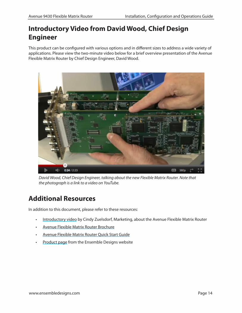
Introductory Video from David Wood, Chief Design EngineerThis product can be configured with various options and in different sizes to address a wide variety of applications. Please view the two-minute video below for a brief overview presentation of the Avenue Flexible Matrix Router by Chief Design Engineer, David Wood.
David Wood, Chief Design Engineer, talking about the new Flexible Matrix Router. Note that the photograph is a link to a video on YouTube.
Additional ResourcesIn addition to this document, please refer to these resources:
• Introductory video by Cindy Zuelsdorf, Marketing, about the Avenue Flexible Matrix Router
• Avenue Flexible Matrix Router Brochure
• Avenue Flexible Matrix Router Quick Start Guide
• Product page from the Ensemble Designs website
www.ensembledesigns.com Page 15
Avenue 9430 Flexible Matrix Router Installation, Configuration and Operations Guide
Chapter 2: System OverviewIn this ChapterThis chapter addresses the following topics:
• Hardware Elements
• Applications
• Example Diagram of Complete Router System with All Options Installed
• Router Expansion Example for a 21 In x 9 Out Router Configuration
• Example Diagram of Router System Using One 9430, One 9440 and One 9435
The Avenue Flexible Matrix Router is a digital Router that can be configured in a variety of matrix sizes and with a variety of options. Highlights of its functionality include ease of expansion, configurable input/output ports, exclusive video thumbnails, configurable control panels, built-in test signal generator and sync pulse generator, and assignable resources such as optional clean and quiet switching on multiple outputs.
The exclusive live thumbnail display in the Router Control Panel and web user interface lets you look at your source before you perform a take.
Highly flexible matrix sizing lets you decide on your own configuration. The basic size is 8 inputs by 2 outputs. You can add user configurable input/output ports up to 28x2 (or 8x22) and any size in between.
The assignable clean switch option gives you full frame synchronization that locks to your house reference so it can switch cleanly between asynchronous sources. VITC captured from the reference input can drive time-scheduled switching.
The Avenue modular digital video router is a flexible, technologically advanced small router. Its flexibility makes it possible to tailor the input/output dimensions to a wide range of applications, including mobile and portable systems, ENG trucks, QC monitoring stations, graphics and post-production islands, edit suites, ingest, production switcher pre-select, master control bypass switching, driving on-set monitors, general utility switching, and numerous other applications.
Hardware ElementsThe hardware elements that make up the Router are as follows:
• 9430 Router Module
• 9440 I/O Expansion Module
• 9435 Dual Clean Switch Submodule
• 5830 Router Control Panel

www.ensembledesigns.com Page 16
Avenue 9430 Flexible Matrix Router Installation, Configuration and Operations Guide
9430 Router ModuleThe control system for the Router resides on this module. The control system, discussed at length in Chapter 4: Configuration, is accessed through a web browser interface.
The 9430 Router Module provides eight dedicated Input Ports and two dedicated Output Ports. In addition to these Inputs and Outputs, the 9430 provides video thumbnail capture, Test Signal Generation, and Genlock/Timing. The smallest possible version of the Flexible Matrix Router consists only of a 9430 module.
Built-in Signal Diagnostics
Circuitry on the 9430 module detects and measures key parameters associated with each video source and makes these parameters available for display on both the hardware and software panels. Parameters include synchronicity and timing, line and frame rate, embedded audio presence/absence, closed caption information, and timecode data.
Fail-Safe Relay Bypass Mechanism
Input 1 and Output 1 are linked together by a fail-safe relay bypass mechanism. In the event of a power or system failure, the signal presented to Input 1 is directly connected to Output 1.
9440 I/O Expansion Module OptionOne or two 9440 I/O Expansion modules can be added to a 9430 to provide additional digital I/O Ports. Each 9440 adds ten bi-directional ports, each of which can be independently configured as an input or an output. These expansion modules attach to either side of the 9430 core module to form a maximum set of three boards. A Router with two 9440 modules has a total of 30 ports.
9435 Dual Clean Switch Submodule OptionEach of the 9435 submodules provide two independent frame-synchronized SDI clean switches, resulting in the ability to switch cleanly between asynchronous sources. Audio sample rate conversion makes the audio output clean and silent. You can use the control system to assign a clean switch to any SDI input or output. Each clean switch can be assigned to one or more outputs by using the Follow port configuration. For more information about port configuration choices, please see Configuring the Router’s Ports on page 54.
A total of two 9435 submodules, providing a total of four independent clean switches, can be installed. The first 9435 mounts on the 9430 Router Module. The second 9435 installs on the 9440 Input Expansion Module in expansion position 1.
5830 Router Control PanelThe Router Control Panel communicates with the 9430 Core module by Ethernet to control the Router and display thumbnail previews of content. An essentially unlimited number of 5830 Router Control Panels can be used in a Router system. You can also access signal diagnostic information from the LCD display on the Router Control Panel. The Router Control Panel is only 1.8” (45mm) deep, so it can be installed in very shallow positions.

www.ensembledesigns.com Page 17
Avenue 9430 Flexible Matrix Router Installation, Configuration and Operations Guide
Long Distance Capability
Because each Router Control Panel connects to the Router over Ethernet, and because Ethernet reaches much farther than coaxial cable, Router Control Panels can be physically located very far away from the Router if desired.
For example, if you need the capability to select sources at the transmitter remotely, such as in the event of either a master control switcher failure or a microwave link failure between the studio and the transmitter, you can use the Router as part of a backup switcher at the transmitter. Sources such as a network feed, a small server or a weather camera could be switched to air in an emergency. You can do the selecting remotely, such as at the studio (or even from home if need be), or from any location with Ethernet access.
ApplicationsThe flexibility of the Avenue Flexible Matrix Router system makes it possible to tailor the input and output dimensions to a diverse range of requirements. Therefore, it can accommodate many environments and applications, including the following:
• Mobile and portable systems
• QC stations
• Graphics and post-production islands
• ENG trucks
• Edit suites
• Ingest
• Production switcher pre-select
• Master control bypass switching
• Driving on-set monitors
• General utility switching
Cuts-Only Master ControlWhen used in conjunction with the Clean Switch option, and because it performs cuts rather than fades and wipes, the Flexible Matrix Router can function as a Cuts-Only Master Control Switcher.
Master Control BypassFacilities such as TV stations can use the Flexible Matrix Router as a Master Control Bypass switcher. With the same sets of feeds going to both the Master Control Switcher and the Flexible Matrix Router, program sources can be switched over to the Flexible Matrix Router during maintenance, for emergencies, or during upgrades.
The Master Control Switcher and the Flexible Matrix Router can both go through a protection switch, such as the Avenue 7455 HD/SD/ASI/310M protection switch, before going on to an MPEG encoder for transmission.

www.ensembledesigns.com Page 18
Avenue 9430 Flexible Matrix Router Installation, Configuration and Operations Guide
Quality Control and Signal MonitoringThe Flexible Matrix Router can be used for quality control and signal monitoring. In a smaller TV station, for example, personnel in engineering can monitor a variety of channels internally. For a larger facility, someone would be performing dedicated quality control monitoring.
For just a quick check, the small LCD display on the Router Control Panel may provide enough of an image preview. Or the LCD can be used as a preview before bringing up the signal on a monitor. The LCD display can also be used to show signal metadata while a monitor can be used to view the picture in a larger format or perhaps as a quad split.
Monitors and Projectors for VenuesThe Flexible Matrix Router brings many sophisticated options to non-broadcast environments, such as corporate meeting rooms, event venues and churches. Because of the simple and accessible Router user interface that runs on a web browser, iPad or Router Control Panel, all video professionals can easily make use of the Router.
For example, a guest speaker who wants to access an assortment of media could have numerous inputs available to them and a number of destinations, such as projector screens or monitors. Using an iPad as a router controller, for instance, the guest speaker would only have to tap the iPad a couple of times to change the source going to a monitor or screen projector. Sources could include still pictures with background music, lyrics, and live feeds.
Another possible source for such environments is content from the Internet. When a computer with Internet access is connected to a BrightEye Mitto™ scan converter, for example, you can upconvert video from YouTube, Skype or any website to SD, HD or 3G SDI video and route that signal to any Router destination. Mac and PC computers, iPhone and iPad can all be used as sources with BrightEye Mitto. All Mitto units accept VGA, DVI and HDMI input signals from PC and Mac computers.
www.ensembledesigns.com Page 19
Avenue 9430 Flexible Matrix Router Installation, Configuration and Operations Guide
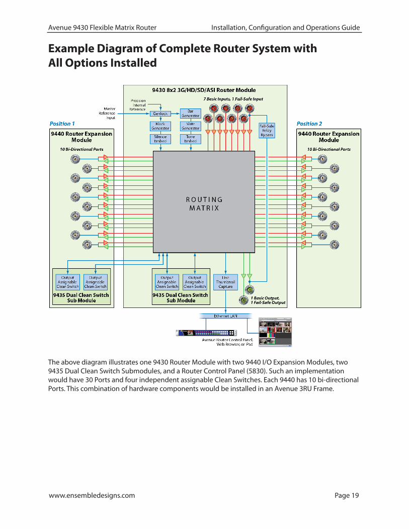
Example Diagram of Complete Router System with All Options Installed
The above diagram illustrates one 9430 Router Module with two 9440 I/O Expansion Modules, two 9435 Dual Clean Switch Submodules, and a Router Control Panel (5830). Such an implementation would have 30 Ports and four independent assignable Clean Switches. Each 9440 has 10 bi-directional Ports. This combination of hardware components would be installed in an Avenue 3RU Frame.

www.ensembledesigns.com Page 20
Avenue 9430 Flexible Matrix Router Installation, Configuration and Operations Guide
Router Expansion Example for a 21 In x 9 Out Router ConfigurationThe 9430 and 9440 modules combine to form a Router with 20 or 30 Ports. They are joined together by three signal routing backplanes which provide the interconnection between the I/O ports on the 9440 and the 9430 core module.
The Router board sets with 20 and 30 Ports install in an Avenue 3RU Frame. The 10 Port Router, consisting of a single 9430 module (and optionally including a 9435 Dual Clean Switch), can be installed in either the Avenue 1RU or 3RU Frames.
30 Port Router: one 9430 Router Module, two 9440 Expansion Modules, two 9435 Clean Switch Submodules, and Routing Backplanes, viewed from the rear. Use the RS-232 or Ethernet to connect with Avenue Control Panel, Master Control, or Automation System.

www.ensembledesigns.com Page 21
Avenue 9430 Flexible Matrix Router Installation, Configuration and Operations Guide
Example Diagram of Router System Using One 9430, One 9440 and One 9435The Flexible Matrix Router is very versatile. Using the Router’s built-in configuration tools, you can create highly customized and sophisticated systems. This produces very efficient, compact solutions to a wide variety of system design challenges. And because the customization is “soft,” the solution can evolve as needs change—in some cases without moving a single cable.
Clean Switches are used to make the Network input synchronous to all outputs and to provide clean and quiet switching (between all inputs) on the output feeding the transmitter. In the example shown above, the switching matrix is configured as 12 Sources and 4 Destinations. Output ports using the Follow feature provide duplicate outputs of selected Destinations, and a loop-through of the Network input.
A large format version of this diagram is available as a PDF here.
9430!8x2 Router Module
9440!Expansion Module
!/12
9440!Expansion Module
!/12
9435!/12
9435!/12
Failsafe!Relay!
Bypass
Clean Switch /!Frame Sync
Black Genembedded!
silence
Bar Gen!w/ Slateembedded!
tone
Clean Switch /!Frame Sync
Genlock
Frame Master Reference
12 Inputs!3G/HD/SD SDI
4 Outputs!3G/HD/SD SDI
Color!Bars Black
Internally Generated
Dedicated!SDI Black Output
Dedicated!Network Output
Feed to Transmiiter!w/ fail-safe
Xmt Feed!Monitoring
Server Record In
QC Monitor
News Room Floor Monitors
Network
News 1
ENG Rx 1
Sat 1
Tower
Cam
Server
1
Server
2
Studio
Wide
Ancho
r Tigh
t
Wx Grap
hics
Still Stor
e
MC
Matrix
In this example, a bypass and backup switcher for Master Control uses just one 9430, one 9440, and one 9435.
www.ensembledesigns.com Page 22
Avenue 9430 Flexible Matrix Router Installation, Configuration and Operations Guide
Chapter 3: InstallationIn this ChapterThis chapter consists of two parts:
Part One: Module Assembly, describes how modules are assembled in the event that you need to add modules or submodules in the future. Original orders are delivered preassembled. Topics addressed include:
• Original Orders Preassembled
• 9430 Router Module
• 9435 Dual Clean Switch Option
• 9440 I/O Expansion Option
Part Two: Required Cable Connections, describes cable connections that all customers must perform, as well as Router Control Panel (5830) installation. Topics addressed include:
• Seating the Board Set Firmly in the Frame
• Installing the BNC Plastic Overlays
• Digital Signal Connections
• Router Control Connections
• Connecting a Timing Reference to the Avenue Frame
• Connecting a Timing Reference to the 9430 Router
• Router Control Panel Installation
Detailed instructions for installing the Avenue frame itself are provided in the Avenue System Overview Manual.

www.ensembledesigns.com Page 23
Avenue 9430 Flexible Matrix Router Installation, Configuration and Operations Guide
PART ONE: MODULE ASSEMBLY
Original Orders PreassembledFor original orders, Ensemble Designs will assemble all modules (the 9430, 9435, and 9440 modules as applicable) before shipping them to your facility. You can then install the assembly into the Avenue frame as a single unit. However, if you add modules at a later time, these instructions will show you how to assemble and install them.
9430 Router ModuleEvery Router will include a 9430 Router Module—a 10 Port Router with 8 dedicated Inputs and 2 dedicated Outputs. Shown below is a 9430 Router Module with no additional modules installed.
The 9430 Router Module with no additional modules installed
www.ensembledesigns.com Page 24
Avenue 9430 Flexible Matrix Router Installation, Configuration and Operations Guide
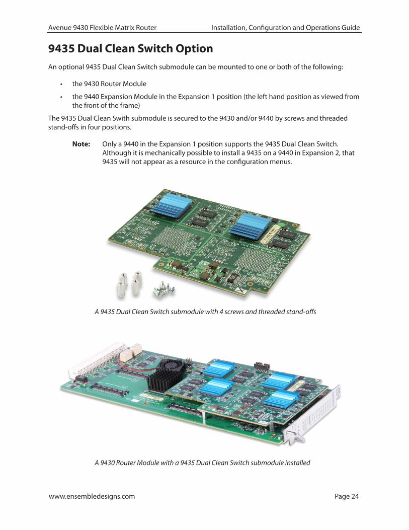
9435 Dual Clean Switch OptionAn optional 9435 Dual Clean Switch submodule can be mounted to one or both of the following:
• the 9430 Router Module
• the 9440 Expansion Module in the Expansion 1 position (the left hand position as viewed from the front of the frame)
The 9435 Dual Clean Swith submodule is secured to the 9430 and/or 9440 by screws and threaded stand-offs in four positions.
Note: Only a 9440 in the Expansion 1 position supports the 9435 Dual Clean Switch. Although it is mechanically possible to install a 9435 on a 9440 in Expansion 2, that 9435 will not appear as a resource in the configuration menus.
A 9435 Dual Clean Switch submodule with 4 screws and threaded stand-offs
A 9430 Router Module with a 9435 Dual Clean Switch submodule installed
www.ensembledesigns.com Page 25
Avenue 9430 Flexible Matrix Router Installation, Configuration and Operations Guide
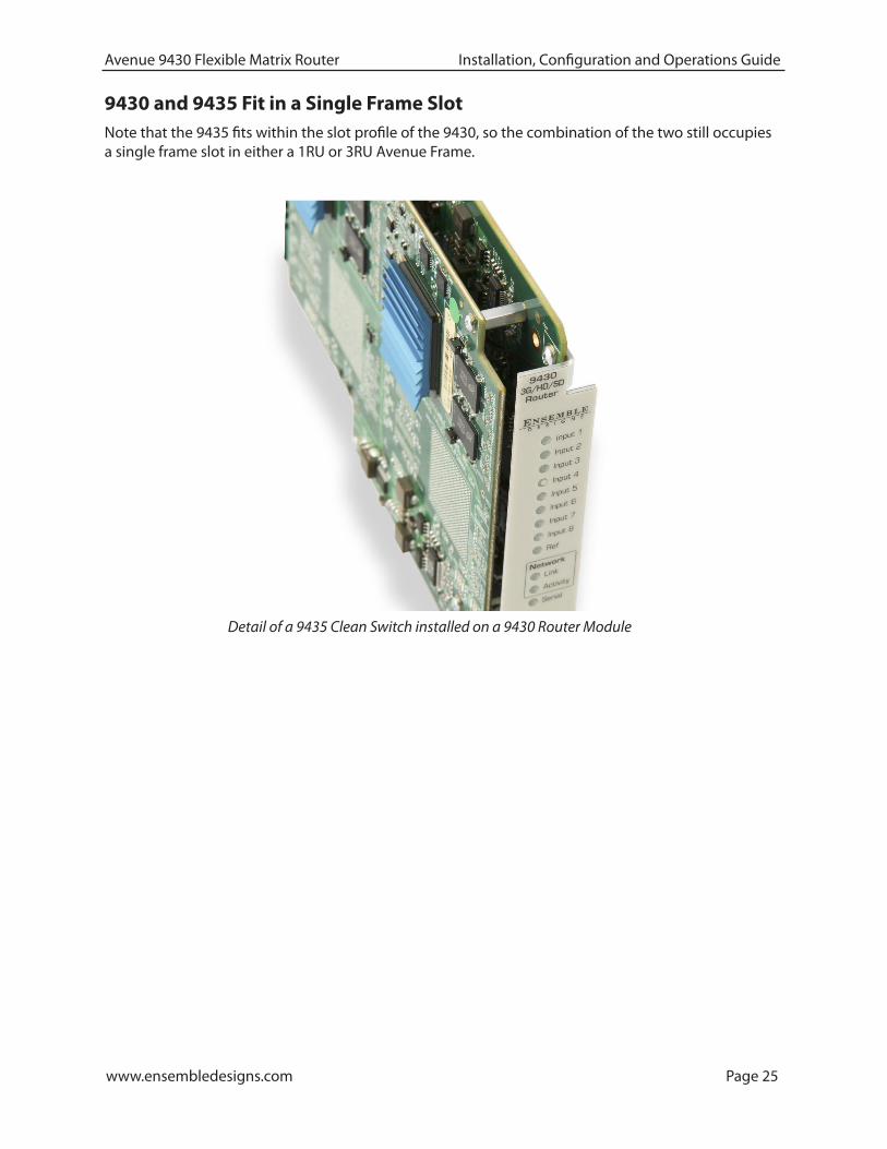
Detail of a 9435 Clean Switch installed on a 9430 Router Module
9430 and 9435 Fit in a Single Frame SlotNote that the 9435 fits within the slot profile of the 9430, so the combination of the two still occupies a single frame slot in either a 1RU or 3RU Avenue Frame.

www.ensembledesigns.com Page 26
Avenue 9430 Flexible Matrix Router Installation, Configuration and Operations Guide
The 9440 I/O Expansion Modules are mechanically attached to a 9430 with screws and stand-offs. The signal electrical connection is made by three high-speed routing backplanes with precision transmission lines designed to support signals up to 3 Gb/s.
Two Types of Routing Backplane KitsThere are two types of routing backplanes, one for 20 Port Routers, and one for 30 Port Routers. Pictured below is the attachment kit for a 30 Port Router.
An attachment kit for a 30 Port Router
9440 I/O Expansion OptionA maximum of two 9440 I/O Expansion Modules can be attached to the 9430 Router Module, one per side.
A 9440 I/O Expansion Module
www.ensembledesigns.com Page 27
Avenue 9430 Flexible Matrix Router Installation, Configuration and Operations Guide
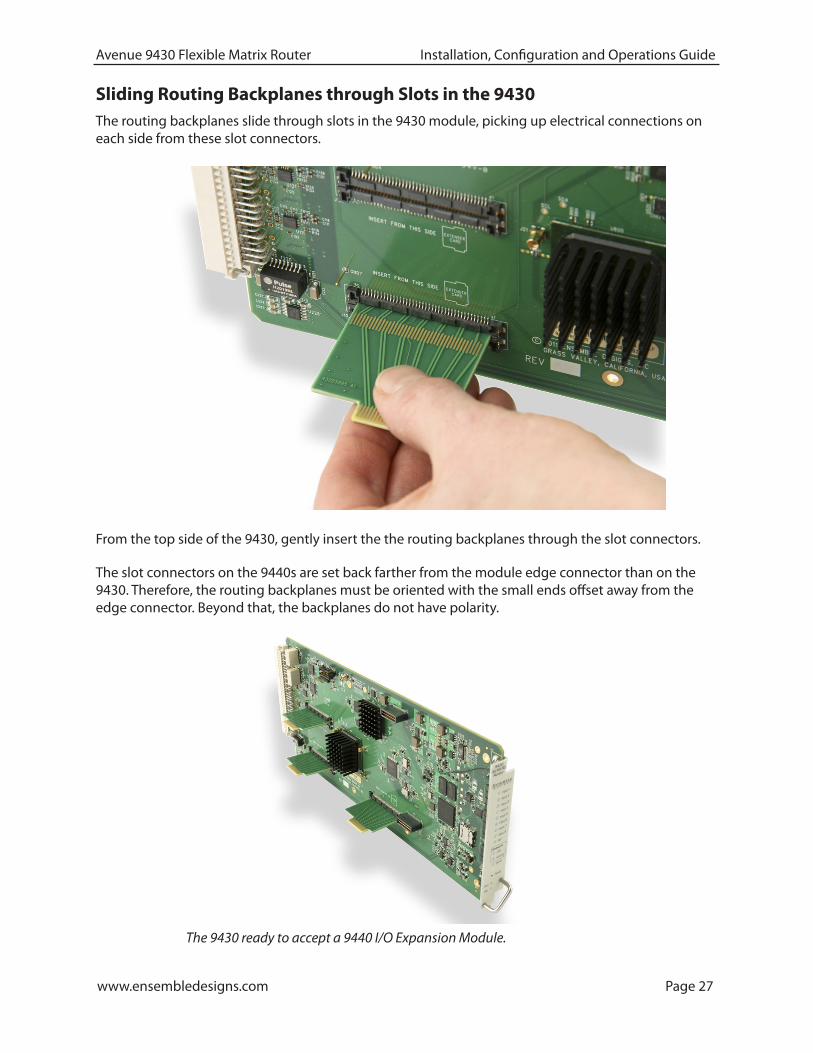
From the top side of the 9430, gently insert the the routing backplanes through the slot connectors.
The slot connectors on the 9440s are set back farther from the module edge connector than on the 9430. Therefore, the routing backplanes must be oriented with the small ends offset away from the edge connector. Beyond that, the backplanes do not have polarity.
Sliding Routing Backplanes through Slots in the 9430The routing backplanes slide through slots in the 9430 module, picking up electrical connections on each side from these slot connectors.
The 9430 ready to accept a 9440 I/O Expansion Module.

www.ensembledesigns.com Page 28
Avenue 9430 Flexible Matrix Router Installation, Configuration and Operations Guide
Installing Stand-Offs on the 9440Install the four stand-offs on each 9440 using one screw per stand-off, as shown below.
Stand-offs on the 9440 Expansion Module
Aligning the 9440 with Routing BackplanesAlign the 9440 with the routing backplanes. Gently guide the backplanes into the smaller slot connectors on the 9440. The narrow end of the backplane will be flush with the connector on the 9440.
Complete the mechanical attachment with screws in the stand-offs.
A completed stand-off with screw in place and backplanes connected to 9430 and 9440

www.ensembledesigns.com Page 29
Avenue 9430 Flexible Matrix Router Installation, Configuration and Operations Guide
An Assembled 30 Port Router ready to install in an Avenue 3RU Frame
Example of Completed AssemblyThe example shown below consists of one 9430 and two 9440s, with backplanes and stand-offs in place, providing 30 ports. This assembly is ready to install in an Avenue 3RU Frame.
PART TWO: REQUIRED CABLE CONNECTIONS
Seating the Board Set Firmly in the FrameInstall the board set in the frame, taking care to insure that the modules are fully seated into the frame backplane connector. This requires more force than with a single module.
Avenue 3RU Frame Partition Divider ConsiderationBecause a multi-board assembly cannot span the divider in the Avenue 3RU Frame between slots 4 and 5, the three modules making up a 30 Port Router cannot be installed in either of these two ranges:
• Slots 3, 4, 5
• Slots 4, 5, 6
It is strongly recommended to take this into account during frame and slot planning. Otherwise, you may have to make a last-minute change to an otherwise carefully planned installation design. Despite this restriction, it is still possible to install as many as three 30 Port Routers in a single 3RU frame.
www.ensembledesigns.com Page 30
Avenue 9430 Flexible Matrix Router Installation, Configuration and Operations Guide
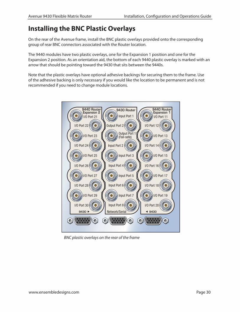
Installing the BNC Plastic OverlaysOn the rear of the Avenue frame, install the BNC plastic overlays provided onto the corresponding group of rear BNC connectors associated with the Router location.
The 9440 modules have two plastic overlays, one for the Expansion 1 position and one for the Expansion 2 position. As an orientation aid, the bottom of each 9440 plastic overlay is marked with an arrow that should be pointing toward the 9430 that sits between the 9440s.
Note that the plastic overlays have optional adhesive backings for securing them to the frame. Use of the adhesive backing is only necessary if you would like the location to be permanent and is not recommended if you need to change module locations.
9440 RouterExpansion 1I/O Port 11
I/O Port 16
I/O Port 20
9430
I/O Port 19
I/O Port 12
I/O Port 15
I/O Port 14
I/O Port 13
I/O Port 18
I/O Port 17
9430 Router
Input Port 1
Output Port 2
Output Port 1(Fail-safe)
Input Port 4
Input Port 8
Input Port 7
Input Port 3
Input Port 2
Input Port 6
Input Port 5
Network/Serial
9440 RouterExpansion 2I/O Port 21
I/O Port 26
I/O Port 30
9430
I/O Port 29
I/O Port 22
I/O Port 25
I/O Port 24
I/O Port 23
I/O Port 28
I/O Port 27
BNC plastic overlays on the rear of the frame

www.ensembledesigns.com Page 31
Avenue 9430 Flexible Matrix Router Installation, Configuration and Operations Guide
Digital Signal ConnectionsThe digital inputs and outputs of the Router are all equally capable of supporting 3G SDI, HD SDI, SD SDI, DVB-ASI, SMPTE 310M and AES audio signals. Connections to sources and destinations are made with 75 ohm coaxial cable.
Cable Length ConsiderationsAn important technical consideration in system wiring is the length of the cables that run between different pieces of equipment. The high frequency content of the serial digital signal, which is attenuated in proportion to the length of the cable, sets an upper limit to the distance over which the interface will work reliably. Beyond that distance, data bit errors will corrupt the signal and render the content unusable. The maximum length for digital grade, RG-6 type cable (such as Belden 1694A) varies according to the data bit-rate of the interface as follows:
Type Bit-Rate Maximum Cable Length
3G HD SDI 3 Gb/s 70 meters (229 feet)
HD SDI 1.5 Gb/s 100 meters (328 feet)
SD SDI 270 Mb/s 300 meters (984 feet)
DVB-ASI 270 Mb/s 300 meters (984 feet)
SMPTE 310M 19.3 Mb/s 100 meters (328 feet), but 30 meters (98 feet) is recommended due to the inherent weakness of the 310M signal
AES 3 Mb/s 100 meters
These numbers are conservative in order to provide a margin of safety that accommodates variations in the output amplitude and jitter content of sources, and the input sensitivity of destinations. Do not exceed these values because when a system is pushed beyond its design limitations, what works one day may not work the next day.
Furthermore, these numbers assume a direct, single cable connection between devices. If the signals are passing through patch panels or cable couplers, the maximum total cable length must be reduced.
Fail-Safe Bypass from Input 1 to Output 1The fail-safe bypass feature of the Avenue Flexible Matrix Router supports a connection from Input 1 to Output 1 in the event of a system or power failure. This is accomplished in a simple manner: Bypass connects the two ports (BNC connectors) together through a passive, mechanical relay. This means that the signal will be carried through the Router even when there is a total loss of power and control. But it also means that the length of the cable between the source and destination is now the total of the input and output cabling. That total must be less than the bit-rate appropriate maximum listed in the above table. And since the Router in bypass mode is effectively a cable coupler, that maximum needs to be further reduced. If other elements or requirements in a system design render the bypass behavior irrelevant, this combined cable length consideration can be disregarded.
It is possible to extend performance beyond these maximums by the use of lower loss RG-11 cable such as Belden 7732LL. The low-loss performance comes from a larger dielectric cross section, so these alternatives are less flexible and more challenging to install and terminate.
Conversely, smaller diameter cable (Belden 1855A) is often favored for its lower weight and higher installation density. These choices must take into account their greater high frequency attenuation.

www.ensembledesigns.com Page 32
Avenue 9430 Flexible Matrix Router Installation, Configuration and Operations Guide
Router Control ConnectionsAlthough the Avenue Frame system is equipped with both RS-232 and Ethernet interfaces, the 9430 has its own dedicated control connections. The communication bandwidth needed to support the live video thumbnails and the expectation on the part of third-party control systems (automation, event control) for a dedicated control port require this.
RS-232 and 100Mb Ethernet Interface Adaptor CableThe connection to both the RS-232 and 100Mb Ethernet interfaces on the 9430 are accomplished through an adaptor cable (part number 23700040) which connects to the HD-15 connector specific to the slot where the 9430 is installed. This adaptor is included with the 9430 module. It is configured as a “Y” cable with a separate leg for the 9-pin D-Sub RS-232 and RJ-45 Ethernet connectors. If only one of these interfaces is required, it is acceptable (though irreversible) to cut off the unwanted leg.
The Ethernet port should be connected with CAT5 or CAT6 cabling to a network Ethernet router or switch to make it accessible to computers on the network. This port can also be directly connected to a computer or to a Router Control Panel (5830). The Ethernet port will auto-sense cable direction, so a cross-over cable is not needed.
The RS-232 port will operate from 1,200 to 115,200 baud.
The configuration of these interfaces and the selection of serial protocol are described in Chapter 6: External Control on page 96.
Rear BNC connectors and the HD-15 connector on the 9430
Adaptor “Y” cable (part number 23700040) for connecting the 9430 to RS-232 and 100Mb Ethernet interfaces
www.ensembledesigns.com Page 33
Avenue 9430 Flexible Matrix Router Installation, Configuration and Operations Guide
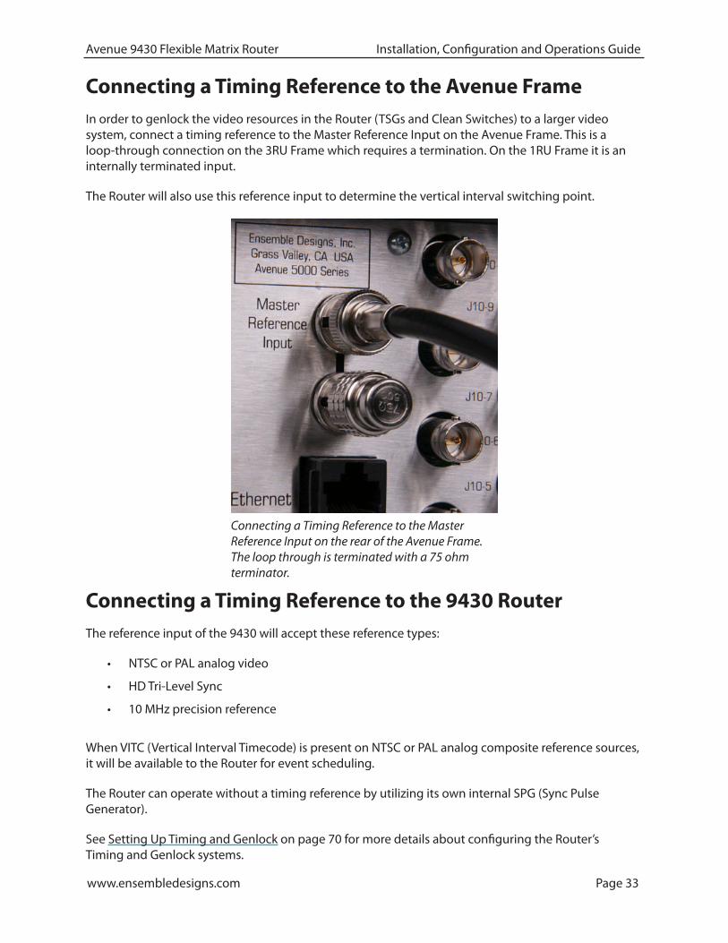
Connecting a Timing Reference to the Avenue FrameIn order to genlock the video resources in the Router (TSGs and Clean Switches) to a larger video system, connect a timing reference to the Master Reference Input on the Avenue Frame. This is a loop-through connection on the 3RU Frame which requires a termination. On the 1RU Frame it is an internally terminated input.
The Router will also use this reference input to determine the vertical interval switching point.
Connecting a Timing Reference to the 9430 RouterThe reference input of the 9430 will accept these reference types:
• NTSC or PAL analog video
• HD Tri-Level Sync
• 10 MHz precision reference
When VITC (Vertical Interval Timecode) is present on NTSC or PAL analog composite reference sources, it will be available to the Router for event scheduling.
The Router can operate without a timing reference by utilizing its own internal SPG (Sync Pulse Generator).
See Setting Up Timing and Genlock on page 70 for more details about configuring the Router’s Timing and Genlock systems.
Connecting a Timing Reference to the Master Reference Input on the rear of the Avenue Frame. The loop through is terminated with a 75 ohm terminator.
www.ensembledesigns.com Page 34
Avenue 9430 Flexible Matrix Router Installation, Configuration and Operations Guide
Router Control Panel Installation
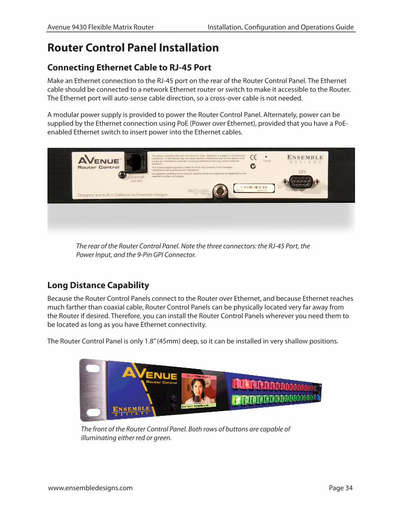
Connecting Ethernet Cable to RJ-45 PortMake an Ethernet connection to the RJ-45 port on the rear of the Router Control Panel. The Ethernet cable should be connected to a network Ethernet router or switch to make it accessible to the Router. The Ethernet port will auto-sense cable direction, so a cross-over cable is not needed.
A modular power supply is provided to power the Router Control Panel. Alternately, power can be supplied by the Ethernet connection using PoE (Power over Ethernet), provided that you have a PoE-enabled Ethernet switch to insert power into the Ethernet cables.
Long Distance CapabilityBecause the Router Control Panels connect to the Router over Ethernet, and because Ethernet reaches much farther than coaxial cable, Router Control Panels can be physically located very far away from the Router if desired. Therefore, you can install the Router Control Panels wherever you need them to be located as long as you have Ethernet connectivity.
The Router Control Panel is only 1.8” (45mm) deep, so it can be installed in very shallow positions.
The front of the Router Control Panel. Both rows of buttons are capable of illuminating either red or green.
The rear of the Router Control Panel. Note the three connectors: the RJ-45 Port, the Power Input, and the 9-Pin GPI Connector.
www.ensembledesigns.com Page 35
Avenue 9430 Flexible Matrix Router Installation, Configuration and Operations Guide
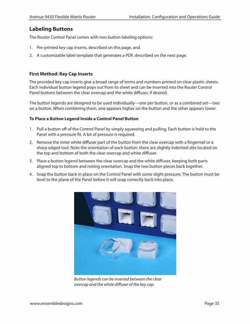
Button legends can be inserted between the clear overcap and the white diffuser of the key cap.
Labeling ButtonsThe Router Control Panel comes with two button labeling options:
1. Pre-printed key cap inserts, described on this page, and
2. A customizable label template that generates a PDF, described on the next page.
First Method: Key Cap Inserts
The provided key cap inserts give a broad range of terms and numbers printed on clear plastic sheets. Each individual button legend pops out from its sheet and can be inserted into the Router Control Panel buttons between the clear overcap and the white diffuser, if desired.
The button legends are designed to be used individually—one per button, or as a combined set—two on a button. When combining them, one appears higher on the button and the other appears lower.
To Place a Button Legend Inside a Control Panel Button
1. Pull a button off of the Control Panel by simply squeezing and pulling. Each button is held to the Panel with a pressure fit. A bit of pressure is required.
2. Remove the inner white diffuser part of the button from the clear overcap with a fingernail or a sharp edged tool. Note the orientation of each button: there are slightly indented slits located on the top and bottom of both the clear overcap and white diffuser.
3. Place a button legend between the clear overcap and the white diffuser, keeping both parts aligned top to bottom and noting orientation. Snap the two button pieces back together.
4. Snap the button back in place on the Control Panel with some slight pressure. The button must be level to the plane of the Panel before it will snap correctly back into place.
www.ensembledesigns.com Page 36
Avenue 9430 Flexible Matrix Router Installation, Configuration and Operations Guide
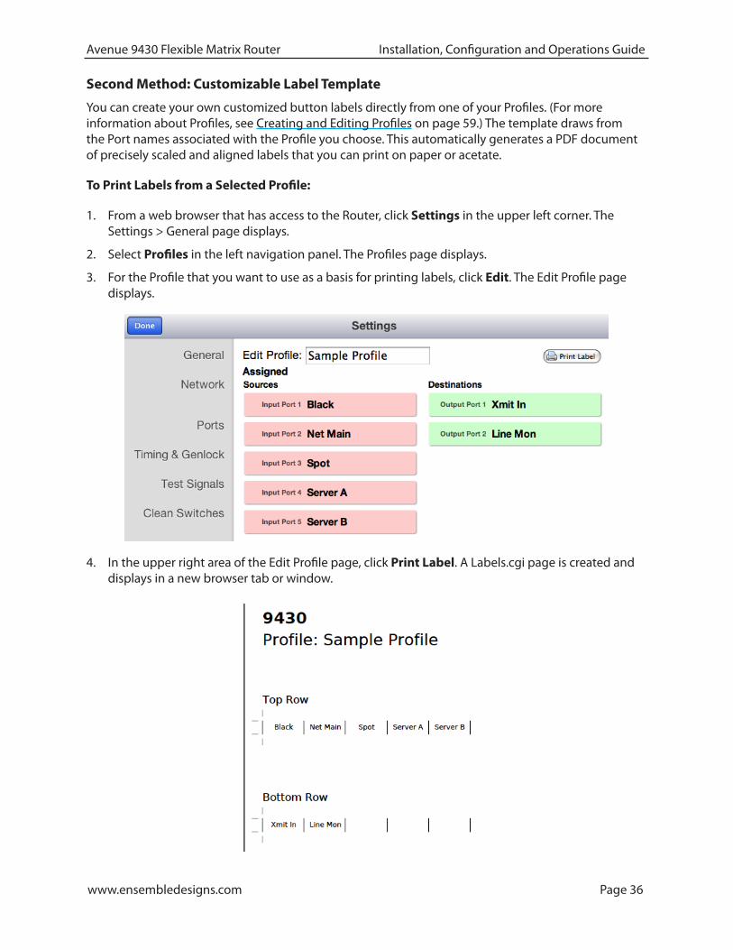
Second Method: Customizable Label Template
You can create your own customized button labels directly from one of your Profiles. (For more information about Profiles, see Creating and Editing Profiles on page 59.) The template draws from the Port names associated with the Profile you choose. This automatically generates a PDF document of precisely scaled and aligned labels that you can print on paper or acetate.
To Print Labels from a Selected Profile:
1. From a web browser that has access to the Router, click Settings in the upper left corner. The Settings > General page displays.
2. Select Profiles in the left navigation panel. The Profiles page displays.
3. For the Profile that you want to use as a basis for printing labels, click Edit. The Edit Profile page displays.
4. In the upper right area of the Edit Profile page, click Print Label. A Labels.cgi page is created and displays in a new browser tab or window.

www.ensembledesigns.com Page 37
Avenue 9430 Flexible Matrix Router Installation, Configuration and Operations Guide
5. Toward the bottom of the generated label page, click the Print icon. If you do not see this toolbar, move your mouse cursor across the screen. It may not constantly display itself.
6. Cut the printed labels into two strips as shown below. Align and place the labels onto the Router Control Panel.

www.ensembledesigns.com Page 38
Avenue 9430 Flexible Matrix Router Installation, Configuration and Operations Guide
GPI ControlThe Router Control Panel is equipped with 8 GPI (General Purpose Interface) inputs. These provide a simple, wire-per-function interface for applications such as:
• Master Control Fault “Panic” Button
• Monitor Follow in Camera Shading
• Crosspoint selection from relay contact closure
Connection to the GPI Inputs is made through the female 9-pin D-Sub connector on the rear of the Router Control Panel.
The pinout of this connector is organized as follows:
Pin # Function1 - 8 GPI Inputs 1 through 8
9 Ground
A GPI function is activated by making a momentary connection between the GPI pin and ground. This can be done with a switch, a relay, or an open-collector driver. The GPI input is internally pulled high, the external control must sink 1 mA.
Functions are assigned to the GPIs through the Control Profile that has been assigned to the panel.
For more information about Profiles, see Creating and Editing Profiles on page 59.
www.ensembledesigns.com Page 39
Avenue 9430 Flexible Matrix Router Installation, Configuration and Operations Guide
Chapter 4: ConfigurationIn this ChapterThis chapter covers the following topics:
• The Router’s Network Environment
• Avenue Touch Screen and Avenue PC Controls
• Initially Connecting to the Router
• Assigning the Router a New IP Address and Subnet Mask
• Establishing Initial Control Point and Profile for Administrator Functions
• Configuring the Router’s Ports
• Creating and Editing Profiles
• Establishing Control Points and Access Authentication
• Setting Up Timing and Genlock
• Configuring Internal Test Signal Generators
• Switch Point Identification
• Working with the Clean Switch Option
The Router's Network EnvironmentThe 9430 Router Module and the Router Control Panels (5830) communicate over a 100 Mb Ethernet LAN (Local Area Network). In this section, we cover the essential factors for configuring the Router in a typical networking environment. Your own networking environment may differ. While we recommend certain practices, you must nevertheless configure the network parameters in each of these devices in accordance with your network.
Avenue Touch Screen and Avenue PC ControlsWhile the primary method for controlling the Router is through the web browser interface discussed in Chapter 5: Operations and Step-by-Step Procedures on page 87, the Avenue Touch Screen or Avenue PC Controls are used for initially assigning the Router and optional Control Panel new IP Addresses and Subnet Masks as needed.
If you do not use Avenue Touch Screen or Avenue PC Controls, see Method Two: For Customers Not Using Avenue Touch Screen or Avenue PC on page 42.

www.ensembledesigns.com Page 40
Avenue 9430 Flexible Matrix Router Installation, Configuration and Operations Guide
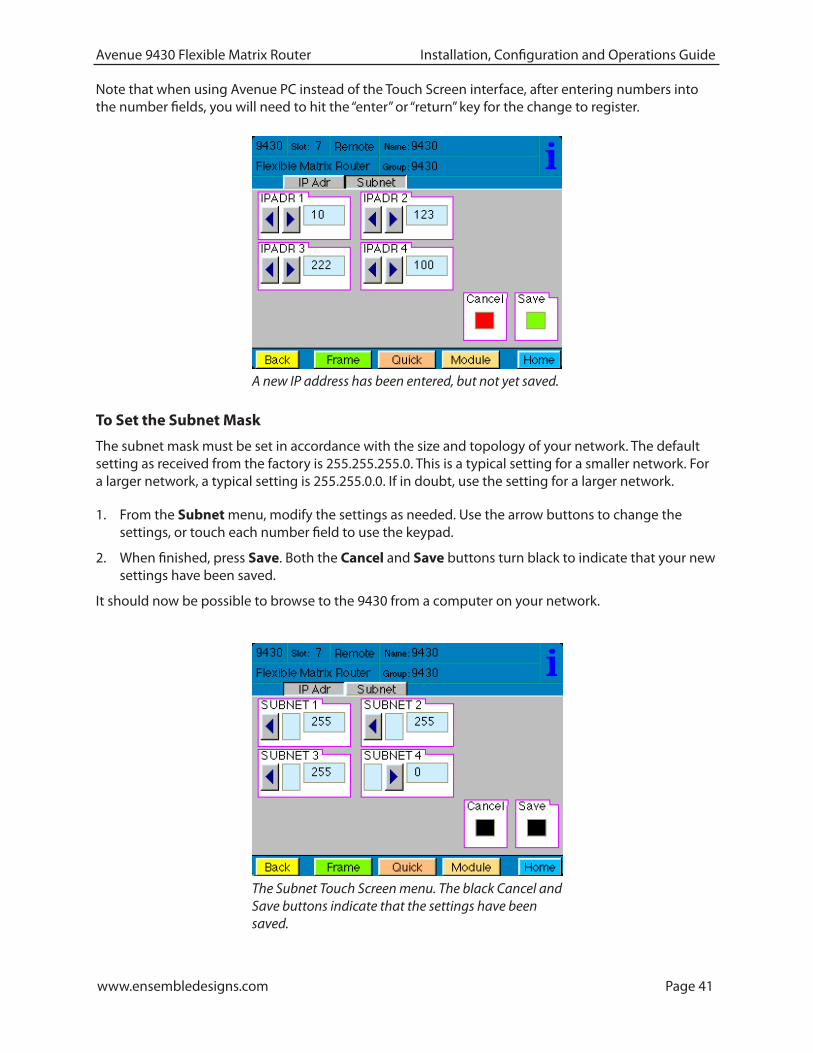
2. From the IP Adr menu, enter the IP address you want to use that is compatible with your own network. The simplest method is to touch each number field, using the keypad to enter the new numbers. For example, you may want to change the IP address to something like the following:
• 10.123.222.100
Assigning the Router a New IP Address and Subnet MaskWhen you initially power up the 9430 as received from the factory, it will take the self-assigned static IP address of 192.168.1.100. The 9430 needs to be configured for a manually assigned static IP address and subnet mask that are compatible with your network environment. The next section of this chapter describes two methods for assigning a new static IP address and subnet mask to the 9430.
1. The first method is for customers who are using either Avenue Touch Screen or Avenue PC to control the Avenue Frame.
2. The second method is for customers who have neither Avenue Touch Screen nor Avene PC.
These are general instructions. We recommend that you consult your IT staff if you are uncertain about any of these network configuration settings.
The Touch Screen interface showing the IP address of the Router as received from the factory.
Method One: For Customers Using Avenue Touch Screen or Avenue PC
To Set the IP Address
1. From the Avenue Frame, select the 9430 module from the Touch Screen. The 9430 menus display.
Initially Connecting to the Router
Establishing Network Connectivity between Controlling Computer and 9430Please review the section Router Control Connections on page 32 if necessary to make sure you have network connectivity between your controlling computer and the 9430. It is critical that the controlling computer be networked to the “Y” adaptor cable which connects to the HD-15 connector specific to the slot in the frame where the 9430 is installed.
www.ensembledesigns.com Page 41
Avenue 9430 Flexible Matrix Router Installation, Configuration and Operations Guide
A new IP address has been entered, but not yet saved.
To Set the Subnet Mask
The subnet mask must be set in accordance with the size and topology of your network. The default setting as received from the factory is 255.255.255.0. This is a typical setting for a smaller network. For a larger network, a typical setting is 255.255.0.0. If in doubt, use the setting for a larger network.
1. From the Subnet menu, modify the settings as needed. Use the arrow buttons to change the settings, or touch each number field to use the keypad.
2. When finished, press Save. Both the Cancel and Save buttons turn black to indicate that your new settings have been saved.
It should now be possible to browse to the 9430 from a computer on your network.
The Subnet Touch Screen menu. The black Cancel and Save buttons indicate that the settings have been saved.
Note that when using Avenue PC instead of the Touch Screen interface, after entering numbers into the number fields, you will need to hit the “enter” or “return” key for the change to register.

www.ensembledesigns.com Page 42
Avenue 9430 Flexible Matrix Router Installation, Configuration and Operations Guide
Method Two: For Customers Not Using Avenue Touch Screen or Avenue PC
Temporarily Changing IP Address on Controlling Computer
When you initially power up the 9430 as received from the factory, it will take the self-assigned static IP address of 192.168.1.100.
In order to connect initially with the Router to assign it an IP address that suits your own network, you must first temporarily change the controlling computer’s IP address so that it is in the same range as the 9430’s default IP address.
For example, you could use the following settings temporarily on the controlling computer:
• IP address: 192.168.1.10
• Subnet mask: 255.255.255.0.
Consideration
Depending on how your computer network is configured, it may be simpler to use a computer, such as a laptop, that is outside of the network solely for the purpose of assigning the Router its new IP address. This may be simpler than temporarily changing the IP address of the controlling computer that is within your network.
Instructions for Temporarily Changing the IP Address for Mac and Windows XP
For the Mac
1. From the dock, click the System Preferences icon. The System Preferences window displays.
2. Click the Network icon. The Network window displays.
3. From the Configure drop-down control, select Manually.
www.ensembledesigns.com Page 43
Avenue 9430 Flexible Matrix Router Installation, Configuration and Operations Guide
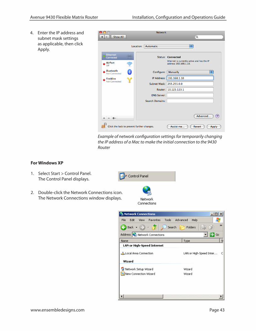
4. Enter the IP address and subnet mask settings as applicable, then click Apply.
Example of network configuration settings for temporarily changing the IP address of a Mac to make the initial connection to the 9430 Router
For Windows XP
1. Select Start > Control Panel. The Control Panel displays.
2. Double-click the Network Connections icon. The Network Connections window displays.
www.ensembledesigns.com Page 44
Avenue 9430 Flexible Matrix Router Installation, Configuration and Operations Guide
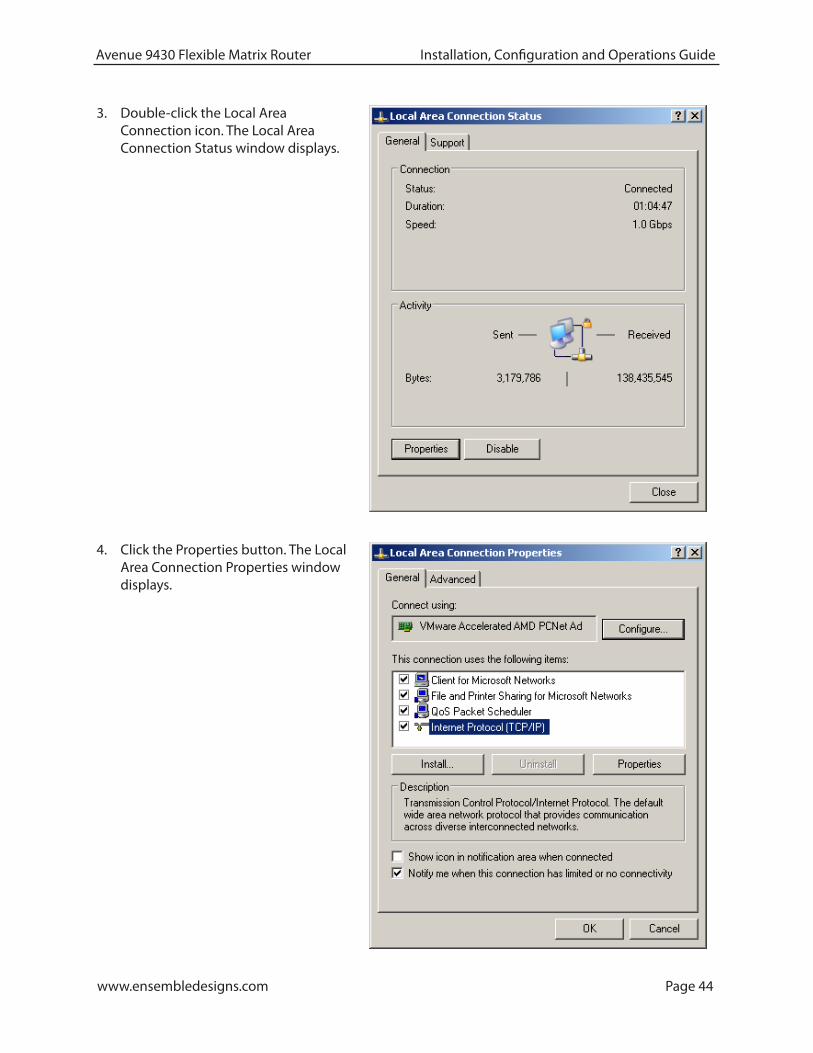
3. Double-click the Local Area Connection icon. The Local Area Connection Status window displays.
4. Click the Properties button. The Local Area Connection Properties window displays.

www.ensembledesigns.com Page 45
Avenue 9430 Flexible Matrix Router Installation, Configuration and Operations Guide
5. Select Internet Protocol (TCP/IP), then click the Properties button. The Internet Protocol (TCP/IP) Properties window displays.
6. Select the radio button for “Use the following IP address.”
7. Enter the IP address and Subnet mask information as applicable, then click OK.
www.ensembledesigns.com Page 46
Avenue 9430 Flexible Matrix Router Installation, Configuration and Operations Guide
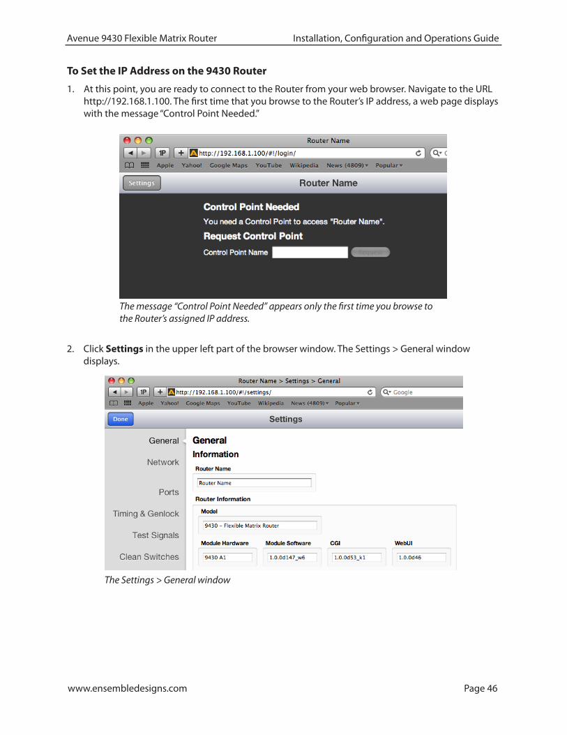
2. Click Settings in the upper left part of the browser window. The Settings > General window displays.
To Set the IP Address on the 9430 Router
1. At this point, you are ready to connect to the Router from your web browser. Navigate to the URL http://192.168.1.100. The first time that you browse to the Router’s IP address, a web page displays with the message “Control Point Needed.”
The message “Control Point Needed” appears only the first time you browse to the Router’s assigned IP address.
The Settings > General window

www.ensembledesigns.com Page 47
Avenue 9430 Flexible Matrix Router Installation, Configuration and Operations Guide
3. From the left navigation panel, click Network. The Network window displays.
4. In the Address field, enter the IP address you want to use for the Router; for example, 10.123.222.100. If you know the Gateway and DNS Server information, enter that information.
5. Click Save Changes, then click Done. You will temporarily lose connection to the Router at this point because it is now using an IP address that is outside of the range of your computer.
Entering the IP address you want to use for the Router that suits your own network environment
An expected temporary loss of connection as part of the initial configuration process

www.ensembledesigns.com Page 48
Avenue 9430 Flexible Matrix Router Installation, Configuration and Operations Guide
Readjusting Controlling Computer’s IP Address to be in Range of Router’s Newly As-signed IP Address
Now that you have set the Router’s IP address away from its factory default in favor of an IP address suitable for your own network environment, you must change the IP address of the controlling computer once again so that it is in a compatible range with the Router’s new IP address.
This may be as simple as reverting to a dynamically assigned IP address if the controlling computer is on a network with a DHCP server compatible with the Router’s new IP address. Or you may want to assign a static IP address, provided that it is one that allows you to access the 9430 with its newly assigned IP address.
Example of readjusting the controlling computer’s IP address to be within range of the Router’s newly assigned IP address.

www.ensembledesigns.com Page 49
Avenue 9430 Flexible Matrix Router Installation, Configuration and Operations Guide
Establishing Initial Control Point and Profile for Administrator FunctionsNow that you have set the Router’s IP address and subnet mask in a manner that suits your network environment, you can start the configuration process. From the controlling computer, connect to the 9430 to establish an initial Control Point for administrator functions.
To Create an Initial Control Point1. Navigate to the 9430’s new IP address with your browser. The Control Point Needed window
displays.
2. From the Control Point Needed window, enter the name you want to use to refer to the initial Control Point (for example, “Router Admin”).
3. Click Request. The message “Control Point Disabled” displays.
4. Click System Settings in the upper left part of the browser window. The Settings > General window displays.

www.ensembledesigns.com Page 50
Avenue 9430 Flexible Matrix Router Installation, Configuration and Operations Guide
The Settings > Control Points window
5. From the left navigation panel, click Network. The Network page displays.
6. Set the Gateway and DNS Server parameters according to your network configuration. In general, these settings will be required only in installations with extended networking requirements, such as a remote site connected by VPN.
7. From the left navigation panel, click Control Points. The Control Points window displays. The Control Point you just requested is listed under Pending Authorization.

www.ensembledesigns.com Page 51
Avenue 9430 Flexible Matrix Router Installation, Configuration and Operations Guide
2. Click Authorize. The Router Admin Control Point now displays in the list of authorized Control Points.
3. Click Save Changes in the upper left area of the window.
4. Click Done.
You should now be presented with a Router Control view with thumbnail icons, as shown below.
To Assign the Factory Default Profile to the Router Admin Control PointYou must assign a Profile that defines which sources and destinations this Control Point can access. To begin with, choose the Factory Default Profile. It provides access to the eight Inputs, two Test Signal Generators, and two Outputs of the basic 9430 module.
1. Under Pending Authorization, select FactoryDefault from the Profile drop-down control.
www.ensembledesigns.com Page 52
Avenue 9430 Flexible Matrix Router Installation, Configuration and Operations Guide
Now that you have set the Router’s IP address, assigned a Profile and authorized an initial Control Point, you have access to all of the Router’s configuration settings.
In the example just discussed, the Router Admin Control Point is specific to the controlling computer. Later sections of this chapter discuss how to create additional Control Points for other computers, laptops, iPads, and Router Control Panels (5830). You can also use external control panels using serial protocols.
For more details, see:
• Creating and Editing Profiles on page 59
• Establishing Control Points and Access Authentication on page 63
• Chapter 6: External Control on page 96
www.ensembledesigns.com Page 53
Avenue 9430 Flexible Matrix Router Installation, Configuration and Operations Guide
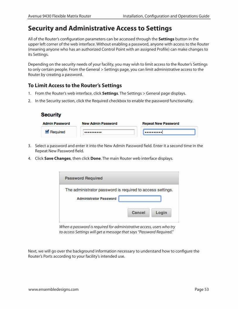
3. Select a password and enter it into the New Admin Password field. Enter it a second time in the Repeat New Password field.
4. Click Save Changes, then click Done. The main Router web interface displays.
Security and Administrative Access to SettingsAll of the Router’s configuration parameters can be accessed through the Settings button in the upper left corner of the web interface. Without enabling a password, anyone with access to the Router (meaning anyone who has an authorized Control Point with an assigned Profile) can make changes to its Settings.
Depending on the security needs of your facility, you may wish to limit access to the Router’s Settings to only certain people. From the General > Settings page, you can limit administrative access to the Router by creating a password.
To Limit Access to the Router’s Settings1. From the Router’s web interface, click Settings. The Settings > General page displays.
2. In the Security section, click the Required checkbox to enable the password functionality.
Next, we will go over the background information necessary to understand how to configure the Router’s Ports according to your facility’s intended use.
When a password is required for administrative access, users who try to access Settings will get a message that says “Password Required.”
www.ensembledesigns.com Page 54
Avenue 9430 Flexible Matrix Router Installation, Configuration and Operations Guide
Configuring the Router's Ports
Planning Router Port ConfigurationTypically, during the planning stage of your Router implementation, you would determine in advance how you want to initially use the router in terms of inputs, outputs, test signals and clean switches.
Cabling Router to Match PlanBased on your plan, connect cables to the ports to match your intended use. After you have completed cabling the router, you will then configure the ports to match how you have wired the router for your facility.
Before going step-by-step through the process of configuring the Router’s ports, it is necessary to go over some background information in order to understand what the configuration options mean.
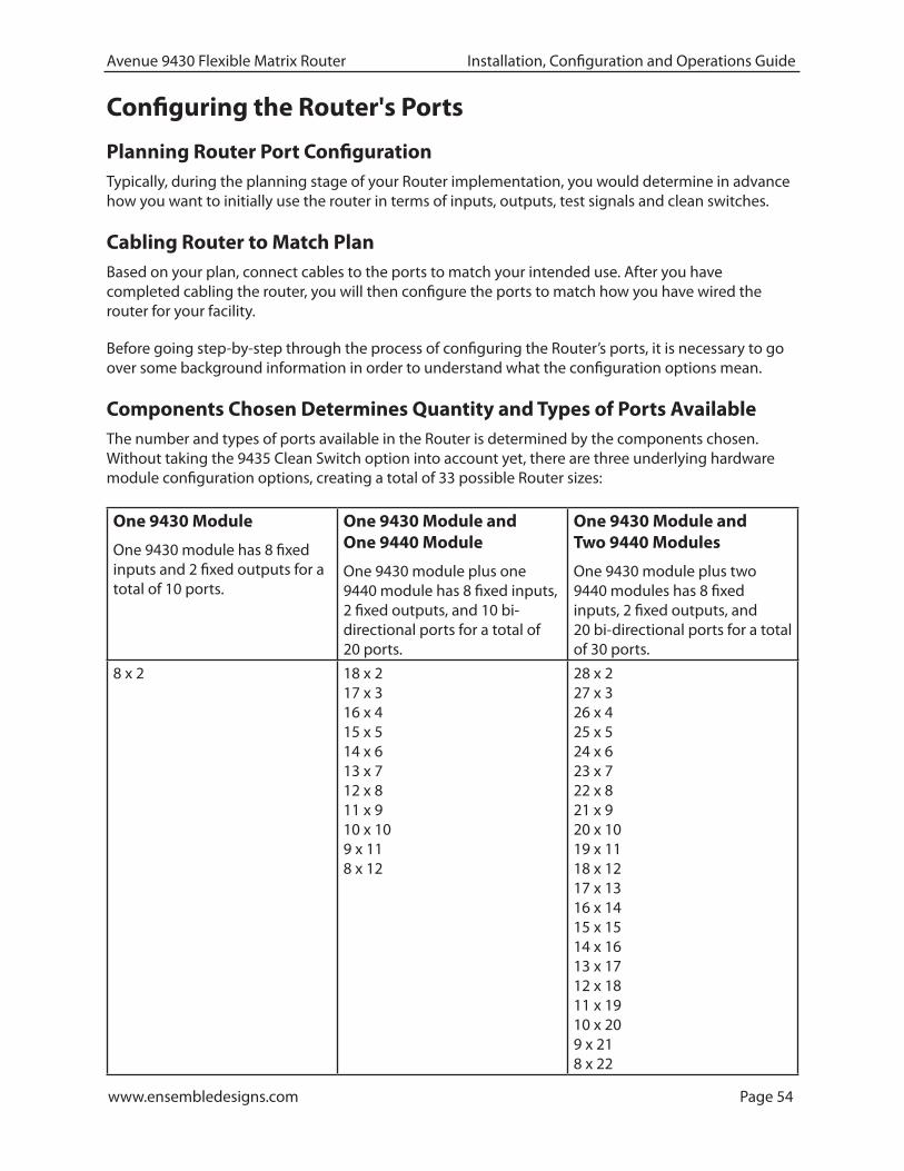
Components Chosen Determines Quantity and Types of Ports AvailableThe number and types of ports available in the Router is determined by the components chosen. Without taking the 9435 Clean Switch option into account yet, there are three underlying hardware module configuration options, creating a total of 33 possible Router sizes:
One 9430 Module
One 9430 module has 8 fixed inputs and 2 fixed outputs for a total of 10 ports.
One 9430 Module and One 9440 Module
One 9430 module plus one 9440 module has 8 fixed inputs, 2 fixed outputs, and 10 bi-directional ports for a total of 20 ports.
One 9430 Module and Two 9440 Modules
One 9430 module plus two 9440 modules has 8 fixed inputs, 2 fixed outputs, and 20 bi-directional ports for a total of 30 ports.
8 x 2 18 x 2 17 x 3 16 x 4 15 x 5 14 x 6 13 x 7 12 x 8 11 x 9 10 x 10 9 x 11 8 x 12
28 x 2 27 x 3 26 x 4 25 x 5 24 x 6 23 x 7 22 x 8 21 x 9 20 x 10 19 x 11 18 x 12 17 x 13 16 x 14 15 x 15 14 x 16 13 x 17 12 x 18 11 x 19 10 x 20 9 x 21 8 x 22

www.ensembledesigns.com Page 55
Avenue 9430 Flexible Matrix Router Installation, Configuration and Operations Guide
Definitions of Port Configuration ChoicesPort configuration choices are described below, followed by detailed examples.
Unassigned
For all Port Types
A port can be set to Unassigned when it is not in use. This will remove it from the list of Sources and Destinations that can be assigned to a Control Profile.
Source
For Fixed Input and Bi-directional Ports
When configured as a Source, a port is an input to the switching matrix. The Source can be given a name, and under that name it will be available for assignment in a Control Profile. Making this selection on bi-directional ports will cause them to operate as inputs.
Destination
For Fixed Output and Bi-directional Ports
Configuring a port as a Destination makes it available for use in Control Profiles under its assigned name as a Router output. A bi-directional port configured as a Destination will cause it to operate as an output.
Follow
For Fixed Output and Bi-directional Ports
Output capable ports can be configured to Follow, or duplicate, the signal on any Source or Destination. The Follow configuration essentially makes a port into a DA. Ports that are configured to Follow will not appear on the list of Sources and Destinations that can be assigned to a Control Profile.
Paired
For all Port Types
This is used to create pairs of Inputs or Outputs to support signals such as Key & Fill, RGB444 Link A & B, or 3D Left & Right. Pairing associates the port to an existing Source or Destination assignment.
Note: While the Paired configuration is valid on all port types, only input capable ports can be paired to a Source, and only output capable ports can be paired to a Destination.
Primary TSG
For Fixed Output and Bi-directional Ports
This Primary TSG configuration delivers the test signal being generated in the Primary TSG to an output port, independently of any user control of the switching matrix.

www.ensembledesigns.com Page 56
Avenue 9430 Flexible Matrix Router Installation, Configuration and Operations Guide
Secondary TSG
For Fixed Output and Bi-directional Ports
The Secondary TSG configuration delivers the test signal being generated in the Secondary TSG to an output port, independently of any user control of the switching matrix.
Note: As described above, only ports that are configured as Sources or Destinations are available to assign to the Source and Destination buttons on a control panel.
Port Configuration Choices Available According to Port TypeThese three port types (fixed input, fixed output, bi-directional) can accept 3G, HD, SD, ASI, 310M, and AES, and can be configured in the following ways:
For Fixed Input
Fixed Input ports can be configured in one of three ways:
1. Unassigned
2. Source (the default on a new installation)
3. Paired
For Fixed Output
Fixed Output ports can be configured in one of six ways:
1. Unassigned
2. Destination (the default on a new installation)
3. Follow
4. Paired
5. Primary TSG
6. Secondary TSG
For Bi-Directional
Bi-directional ports can be configured in one of seven ways:
1. Unassigned (default on new installation)
2. Source
3. Destination
4. Follow
5. Paired
6. Primary TSG
7. Secondary TSG

www.ensembledesigns.com Page 57
Avenue 9430 Flexible Matrix Router Installation, Configuration and Operations Guide
Implementing Router Port Configuration PlanNow that we have covered the background context for numbers and types of Router ports available and what the various configuration selections mean, you are ready to configure the Router’s ports.
To Configure the Router’s Ports
From the left navigation panel, select Ports. The Ports page displays. Initially, all the ports show “Unassigned” for the Type drop-down control.
Configuring Ports: Making a selection from the Type drop-down control for Output Port 1

www.ensembledesigns.com Page 58
Avenue 9430 Flexible Matrix Router Installation, Configuration and Operations Guide
On the Ports page, take the following steps for each port that you plan to use:
1. Select its Type from the Type drop-down control.
2. Indicate a Name (this is the Port’s name that is visible when creating Profiles).
3. If applicable, make a selection from the Follow/Pair drop-down control.
4. Click Save Changes near the upper left area of the browser window to save your changes, or click Abandon Changes if you want to cancel your changes.
Now that you have configured the Router’s Ports, the next stage of Router configuration is to create Profiles and Control Points to accommodate as many users as you need in your facility.
An Example Port Configuration

www.ensembledesigns.com Page 59
Avenue 9430 Flexible Matrix Router Installation, Configuration and Operations Guide
Creating and Editing ProfilesA Profile provides each Control Point with a configured view of the Sources and Destinations on the Router. A Profile defines which Sources and Destinations can be accessed from any given Control Point.
A Profile also defines the order in which Sources and Destinations display for a Control Point. This ordering feature is of particular interest in the case of RS-232 and TCP/IP control for automation because it provides a simple means to map Sources and Destinations to suit the automation protocol.
Every Control Point, such as a Router Control Panel (5830), a web browser, an iPad, or a serial interface for external control, must have a Profile assigned to it in order for that Control Point to be able to use the Router. Multiple Control Points can share the same Profile.
Each Profile can be customized to have access to unique combinations of not only Destinations, but also Sources.
Characteristics of Profiles• Required for every Control Point
• Show only Sources and Destinations
• Define which Sources and Destinations can be accessed
• Define the order in which Sources and Destinations are displayed
• Can be assigned to multiple Control Points
Creating an Initial Set of ProfilesComplete the process of creating as many profiles as your Router users will require. While you can always create additional Profiles or edit existing ones, you may want to systematically think through your users’ needs to determine what the initial set of Profiles will be. This will simplify the overall configuration process as you begin assigning Profiles to Control Points.
To Create a Profile
1. From the left navigation panel, click Profiles. The Profiles page displays.
2. Enter a profile name in the New Profile field.
3. Click Create. The new Profile is listed on the Profiles page.
4. Next to the newly created Profile, click Edit. The Edit Profile page displays. At the outset of creating a new profile, all the available Sources and Destinations are presented.
5. Click and drag unassigned Sources and Destinations up to the assigned area as needed for this specific profile. Note that you can rearrange the order as desired. Additionally, you can include empty spaces to create groupings of Sources and Destinations by clicking and dragging a Space icon up to be a source or destination.
6. When finished, click Save Changes in the upper left part of the screen, then click Done.
This newly created Profile is now available to assign to one or more Control Points.
Repeat steps 1 through 6 until you have as many Profiles as you need.

www.ensembledesigns.com Page 60
Avenue 9430 Flexible Matrix Router Installation, Configuration and Operations Guide
Examples of ProfilesAfter the functions of the Ports have been defined, the available Sources and Destinations are selectively assigned to Profiles.
Ports that are configured as Follow, Paired, or Unassigned are not available to a Profile since they cannot be “controlled.”
Master Control Room (MCR) 10 x 3
In the example below, there are ten Sources and three Destinations for a Master Control Room Profile named “MCR.” In this example, all available Sources and Destinations have been assigned.
An example of a Master Control Room (MCR) Profile with 10 Sources and 3 Destinations

www.ensembledesigns.com Page 61
Avenue 9430 Flexible Matrix Router Installation, Configuration and Operations Guide
MCR Profile Edited and Reordered to 8 x 3
This Profile has been edited to remove access to two of the Sources (ENG Rx 1 and News 1). In addition, blank spaces have been inserted to organize the selections as they are presented on a control panel. Those “blanks” will produce unused buttons on the panel.
This profile also has the Sources and Destinations in a different order and will be reflected in the button assignment on a control panel. If this profile were assigned to the serial interface for automation control, the order and spacing of Sources and Destinations would “map” the external control to the Router.
An edited and reordered Master Control Room (MCR) Profile with 8 Sources and 3 Destinations

www.ensembledesigns.com Page 62
Avenue 9430 Flexible Matrix Router Installation, Configuration and Operations Guide
MCR Profile Edited to 8 x 1
This Profile has been further edited by removing two Destinations. The result is a Profile that allows control over only a single output. If assigned to a Router Control Panel (5830), this would effectively create a single destination panel.
An edited Master Control Room (MCR) Profile with 8 Sources and 1 Destination

www.ensembledesigns.com Page 63
Avenue 9430 Flexible Matrix Router Installation, Configuration and Operations Guide
Establishing Control Points and Access AuthenticationThere are many ways to control the Router and many possible Control Points. In order to manage these and selectively limit access, each possible Control Point must be authenticated.
An administrator grants access to Control Points through configuring the Control Points page. Access the Control Points page by selecting Control Points from the left navigation panel of the web interface. The administrator assigns a previously created Profile to each of the various Control Points. Control Points can be either assigned or requested. These methods are discussed in more detail shortly.
Characteristics of Control PointsFor each Control Point, only the Sources and Destinations that have been defined by its assigned Profile will be available.
For a Control Point to work, it must meet these conditions:
• It must be authenticated, meaning that the Enabled check box is selected in the Control Points window.
• It must have a Profile assigned to it.
If these conditions are not met, the browser window displays the message, “Control Point Disabled.”
The Control Points window showing three Control Points. Note that these Control Points are enabled (the Enabled check box is selected) and have Profiles assigned to them.
www.ensembledesigns.com Page 64
Avenue 9430 Flexible Matrix Router Installation, Configuration and Operations Guide
Examples of Control Points• 5830 Router Control Panel
• Laptops, iPads and other computers using a web browser
• External control using serial protocols
Configuring the 5830 Router Control PanelConfiguring the Router Control Panel involves:
• Connecting it to the network with an Ethernet cable,
• Turning on the power, (unless it is being powered using Power over Ethernet, or PoE),
• Determining whether to use a static (the default) or dynamic IP address,
• Granting it access to the Router, and
• Assigning it a Profile.
Note: Please connect the Router Control Panel to the network before turning on its power. The Router Control Panel can be powered using PoE (if you have a PoE switch upstream from the Panel), or it can be powered by the power supply included with each Panel.
Assigning an IP Address to the 1RU Control PanelThe 5830 1RU Control Panel comes from the factory with the following defaults:
• Static IP Address: 192.168.1.101
• Subnet: 255.255.255.0
You can change this configuration by accessing the 5830 from a web browser. To do this, you will need a computer whose network configuration is compatible with the 5830 defaults. In general, this will require that the computer be connected to the same Ethernet switch as the 5830. A WiFi connection will work only if it provides access to the 5830 subnet. The computer will need an address in the range of 192.168.1.0 to 192.168.1.254 in order to connect to the 5830.
Once you can browse to the 5830, you will see the following Settings > General window:
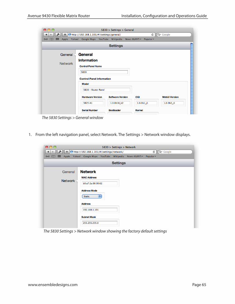
www.ensembledesigns.com Page 65
Avenue 9430 Flexible Matrix Router Installation, Configuration and Operations Guide
1. From the left navigation panel, select Network. The Settings > Network window displays.
The 5830 Settings > General window
The 5830 Settings > Network window showing the factory default settings
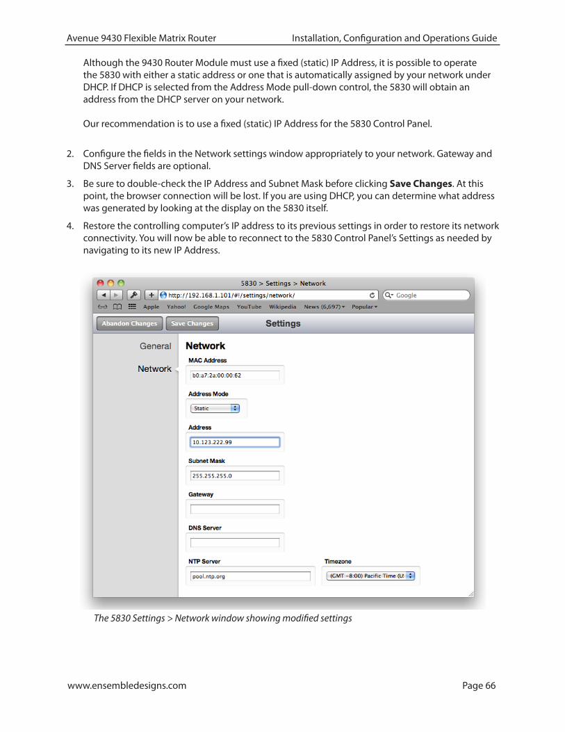
www.ensembledesigns.com Page 66
Avenue 9430 Flexible Matrix Router Installation, Configuration and Operations Guide
Although the 9430 Router Module must use a fixed (static) IP Address, it is possible to operate the 5830 with either a static address or one that is automatically assigned by your network under DHCP. If DHCP is selected from the Address Mode pull-down control, the 5830 will obtain an address from the DHCP server on your network. Our recommendation is to use a fixed (static) IP Address for the 5830 Control Panel.
2. Configure the fields in the Network settings window appropriately to your network. Gateway and DNS Server fields are optional.
3. Be sure to double-check the IP Address and Subnet Mask before clicking Save Changes. At this point, the browser connection will be lost. If you are using DHCP, you can determine what address was generated by looking at the display on the 5830 itself.
4. Restore the controlling computer’s IP address to its previous settings in order to restore its network connectivity. You will now be able to reconnect to the 5830 Control Panel’s Settings as needed by navigating to its new IP Address.
The 5830 Settings > Network window showing modified settings

www.ensembledesigns.com Page 67
Avenue 9430 Flexible Matrix Router Installation, Configuration and Operations Guide
Creating a Control Point for the 5830 Panel1. Browse to the 9430 Settings > Control Points page.
2. Under the heading Add Control Point, enter a name for the 5830 Panel in the Name field.
3. Select FactoryDefault from the Profile drop-down control.
4. Enter the IP address of the 5830 into the Address field.
5. Click Add.
6. Click Done.
At this point, now that you have assigned a compatible IP address to the Control Panel and you have added it as a Control Point, it will be able to connect to the Router.
The 9430 Settings > Control Points window showing the process of adding the 5830 Control Panel as a Control Point
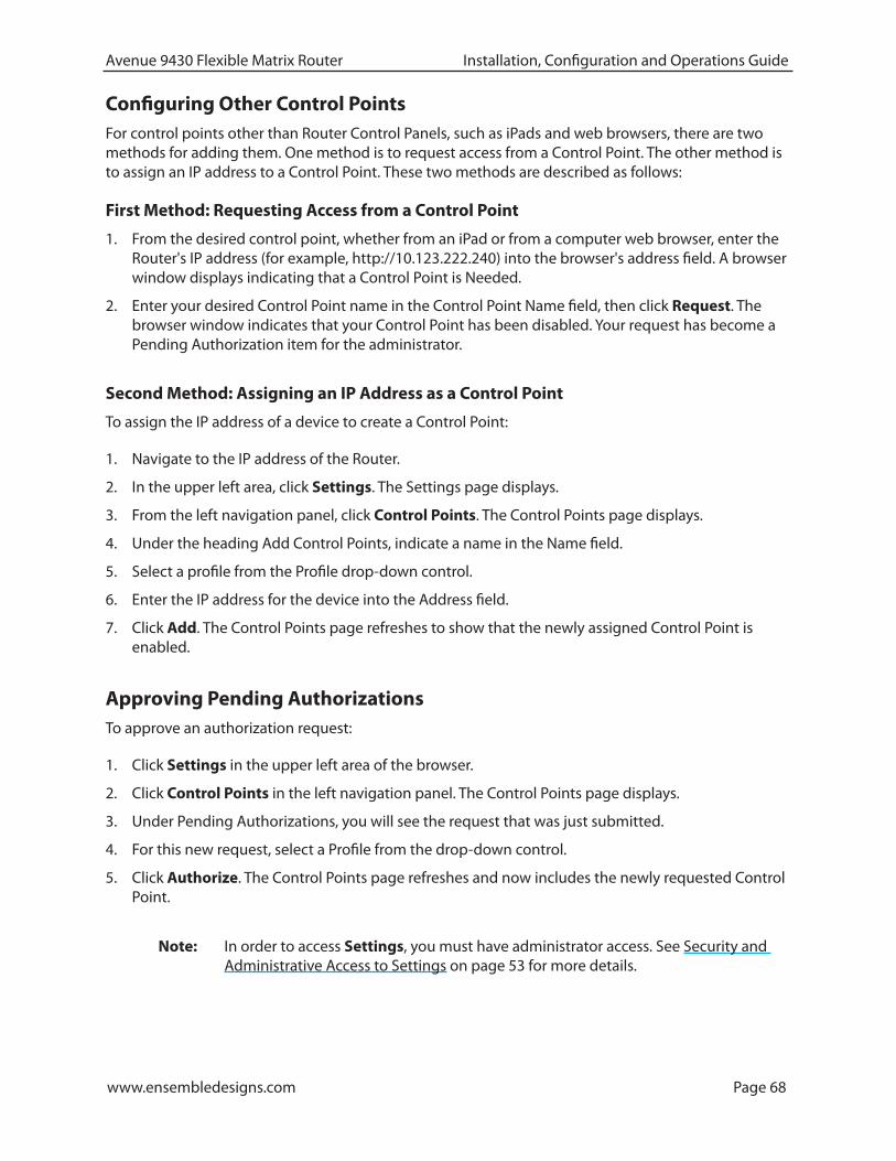
www.ensembledesigns.com Page 68
Avenue 9430 Flexible Matrix Router Installation, Configuration and Operations Guide
Configuring Other Control PointsFor control points other than Router Control Panels, such as iPads and web browsers, there are two methods for adding them. One method is to request access from a Control Point. The other method is to assign an IP address to a Control Point. These two methods are described as follows:
First Method: Requesting Access from a Control Point
1. From the desired control point, whether from an iPad or from a computer web browser, enter the Router's IP address (for example, http://10.123.222.240) into the browser's address field. A browser window displays indicating that a Control Point is Needed.
2. Enter your desired Control Point name in the Control Point Name field, then click Request. The browser window indicates that your Control Point has been disabled. Your request has become a Pending Authorization item for the administrator.
Second Method: Assigning an IP Address as a Control Point
To assign the IP address of a device to create a Control Point:
1. Navigate to the IP address of the Router.
2. In the upper left area, click Settings. The Settings page displays.
3. From the left navigation panel, click Control Points. The Control Points page displays.
4. Under the heading Add Control Points, indicate a name in the Name field.
5. Select a profile from the Profile drop-down control.
6. Enter the IP address for the device into the Address field.
7. Click Add. The Control Points page refreshes to show that the newly assigned Control Point is enabled.
Approving Pending AuthorizationsTo approve an authorization request:
1. Click Settings in the upper left area of the browser.
2. Click Control Points in the left navigation panel. The Control Points page displays.
3. Under Pending Authorizations, you will see the request that was just submitted.
4. For this new request, select a Profile from the drop-down control.
5. Click Authorize. The Control Points page refreshes and now includes the newly requested Control Point.
Note: In order to access Settings, you must have administrator access. See Security and Administrative Access to Settings on page 53 for more details.

www.ensembledesigns.com Page 69
Avenue 9430 Flexible Matrix Router Installation, Configuration and Operations Guide
Number of Control Points That Can Operate SimultaneouslyThe Router performs best with a maximum of four control points operating simultaneously. The Router’s data bandwidth is shared across all of the control points. Each additional control point adds an incremental load on the system. When more than four control points are being used, the Router’s video thumbnail display performance may begin to degrade.
Asymmetrical Bandwidth Requirements
The continuous delivery of video thumbnails to each control point requires more bandwidth than is required for performing takes. The video thumbnails, comprising the vast bulk of the data, flow outward from the 9430 to each control point. The return data, in contrast, consists primarily of crosspoint commands, or takes. Because the Router has greater bandwidth for takes, the execution of takes will still be quite responsive even in a large system with markedly degraded thumbnail refresh performance.
Best Practice: Closing Web Browser Control Points When Not In Use
To minimize the load on the Router, it is recommended to close any Web Browser Control Points that are not being used.
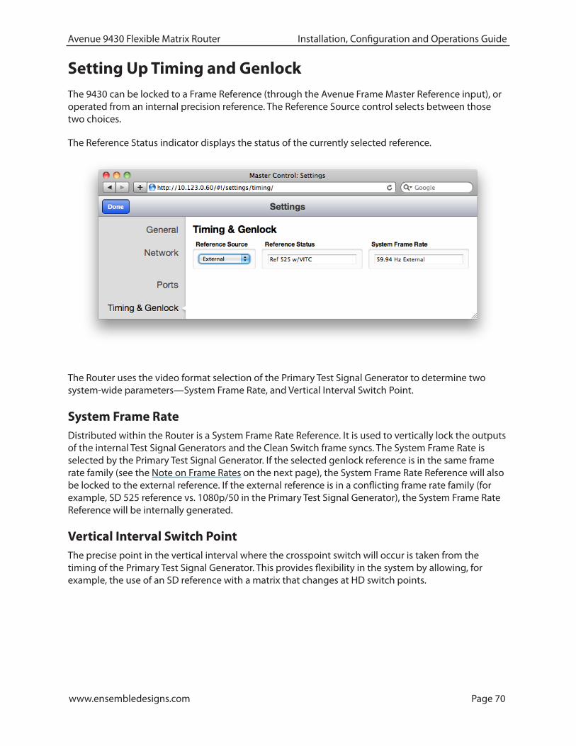
www.ensembledesigns.com Page 70
Avenue 9430 Flexible Matrix Router Installation, Configuration and Operations Guide
Setting Up Timing and GenlockThe 9430 can be locked to a Frame Reference (through the Avenue Frame Master Reference input), or operated from an internal precision reference. The Reference Source control selects between those two choices.
The Reference Status indicator displays the status of the currently selected reference.
The Router uses the video format selection of the Primary Test Signal Generator to determine two system-wide parameters—System Frame Rate, and Vertical Interval Switch Point.
System Frame RateDistributed within the Router is a System Frame Rate Reference. It is used to vertically lock the outputs of the internal Test Signal Generators and the Clean Switch frame syncs. The System Frame Rate is selected by the Primary Test Signal Generator. If the selected genlock reference is in the same frame rate family (see the Note on Frame Rates on the next page), the System Frame Rate Reference will also be locked to the external reference. If the external reference is in a conflicting frame rate family (for example, SD 525 reference vs. 1080p/50 in the Primary Test Signal Generator), the System Frame Rate Reference will be internally generated.
Vertical Interval Switch PointThe precise point in the vertical interval where the crosspoint switch will occur is taken from the timing of the Primary Test Signal Generator. This provides flexibility in the system by allowing, for example, the use of an SD reference with a matrix that changes at HD switch points.

www.ensembledesigns.com Page 71
Avenue 9430 Flexible Matrix Router Installation, Configuration and Operations Guide
Note on Frame RatesDespite the large number of video formats supported by the Router, there are only three possible frame rate families.
50 Hz The 50 Hz frame rate family includes 25 Hz and 50 Hz frame and field rates. This family includes all of the “PAL” related standards in both standard and high definition.
59.94 Hz All of the NTSC-derived standards, including 23.98, 29.97, and 59.94 Hz field and frame rates. There is a 4 Frame to 5 Frame relationship between 23.98 and 59.94 which allows these to peacefully co-exist.
60 Hz The “not quite 60 Hz” challenges of the 59.94 world are addressed with this family which includes 24 Hz, 30 Hz, and 60 Hz field and frame rates. Though not used for broadcast, this family is useful for film rate and scientific/industrial applications.
The vast majority of applications, even those including both SD and HD formats, will all fall within a single frame rate family. For example, as members of the 59.94 family, both SD 525 and 1080i/59.94 can be simultaneously vertically locked to a single reference.

www.ensembledesigns.com Page 72
Avenue 9430 Flexible Matrix Router Installation, Configuration and Operations Guide
Configuring Internal Test Signal GeneratorsThe 9430 is equipped with two independent internal Test Signal Generators (TSG). These generators are driven from the genlock source chosen by the Reference Source control on the Timing and Genlock page.
Each TSG can be independently configured for format, frame rate, and test pattern. The TSG outputs will always be clock-locked to the reference source. Further, they will be vertically locked and timed if the video standard the TSG is configured for is compatible with the provided reference.
Because the Router generates the test signals internally, the TSGs are available as sources in the Router (without consuming a physical input BNC) and can be selected to any output destination. Source names can be assigned to them in the Port Configuration menu, and their position on control panels is assigned in the Profiles menu.
Test Signal Generator ConfigurationThere are two sets of configuration controls, one for each TSG. These configurations are independent, allowing the two generators to operate in different formats – and even at different frame rates. To configure them to the same standard, and to set them to matching timing (relative to the genlock reference), make the same settings for Standard, Vertical Timing, and Horizontal Timing.
InternalPrecision
Reference
Slate/Cyclops
Test SigGen 2
Slate/Cyclops
Test SigGen 1
AudioEmbed
AudioEmbed
ToneGen
GenlockMaster
ReferenceInput

www.ensembledesigns.com Page 73
Avenue 9430 Flexible Matrix Router Installation, Configuration and Operations Guide
The Test Signals configuration page
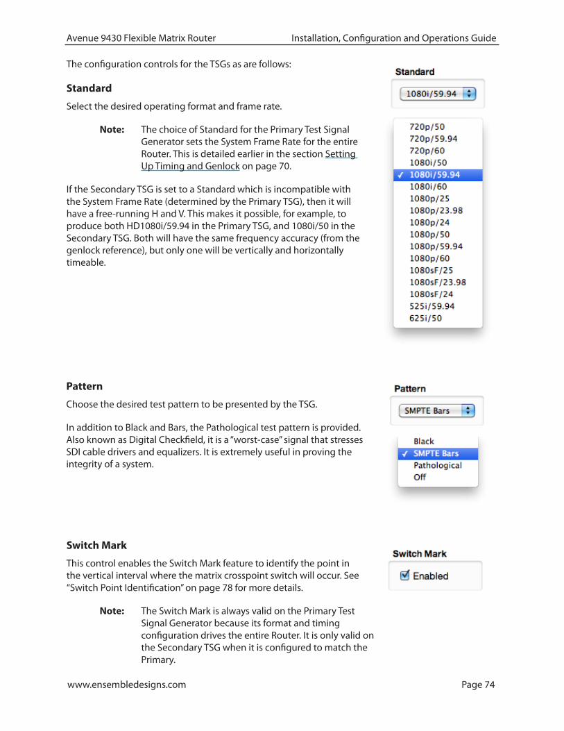
www.ensembledesigns.com Page 74
Avenue 9430 Flexible Matrix Router Installation, Configuration and Operations Guide
The configuration controls for the TSGs as are follows:
Standard
Select the desired operating format and frame rate.
Note: The choice of Standard for the Primary Test Signal Generator sets the System Frame Rate for the entire Router. This is detailed earlier in the section Setting Up Timing and Genlock on page 70.
If the Secondary TSG is set to a Standard which is incompatible with the System Frame Rate (determined by the Primary TSG), then it will have a free-running H and V. This makes it possible, for example, to produce both HD1080i/59.94 in the Primary TSG, and 1080i/50 in the Secondary TSG. Both will have the same frequency accuracy (from the genlock reference), but only one will be vertically and horizontally timeable.
Switch Mark
This control enables the Switch Mark feature to identify the point in the vertical interval where the matrix crosspoint switch will occur. See “Switch Point Identification” on page 78 for more details.
Note: The Switch Mark is always valid on the Primary Test Signal Generator because its format and timing configuration drives the entire Router. It is only valid on the Secondary TSG when it is configured to match the Primary.
Pattern
Choose the desired test pattern to be presented by the TSG.
In addition to Black and Bars, the Pathological test pattern is provided. Also known as Digital Checkfield, it is a “worst-case” signal that stresses SDI cable drivers and equalizers. It is extremely useful in proving the integrity of a system.

www.ensembledesigns.com Page 75
Avenue 9430 Flexible Matrix Router Installation, Configuration and Operations Guide
Vertical and Horizontal Timing
The Vertical and Horizontal Timing controls adjust the timing of the TSG relative to the genlock reference. Setting the H and V parameters to 0 will “zero” time the TSG to the reference. Negative values will cause the TSG to be early with respect to the reference; positive values will make the TSG later in time.
When the Router is being operated from an external 10 MHz reference, or when it is configured to use its internal precision frequency reference, there is no external video reference against which H and V timing can be adjusted. In that case, all of the resources in the router (the TSGs and the Clean Switch/Synchronizers) will be adjusted against a common, internally generated video timing reference. This means that they can be adjusted relative to each other. If all of their H and V Timing parameters are set to identical values (like 0), they will all be locked (synchronous) to each other and they will all be in vertical and horizontal alignment with each other.
Note: The timing adjustments for the Primary Test Signal Generator are also used to position the vertical interval switching point in the Router’s matrix. The timing of the Primary TSG can be compared to other sources on a Waveform Monitor to ensure that the switch point will be properly aligned to the sources feeding the Router.
Audio Embedding
Each TSG has an Audio Embedder (Multiplexer) that can embed 16 channels of audio into the TSG SDI output. Audio is embedded in groups, each of which contains 4 channels. There are 9 audio sources for each channel – 8 tone generators, plus silence.
Note: In the world of digital audio, there is a big difference between “Silence” and “no signal present.” In the same way that Black is a legitimate video signal, digital silence must be sent to destinations rather than just sending “nothing.” Thus, TSGs should generally be configured to embed ALL of the groups that may be in use in a facility, with Silence chosen as the audio signal for channels where no content is needed or desired. Otherwise, switching between a TSG with only one group enabled, and a source with two groups of embedded audio present, will produce undesirable effects in downstream equipment.
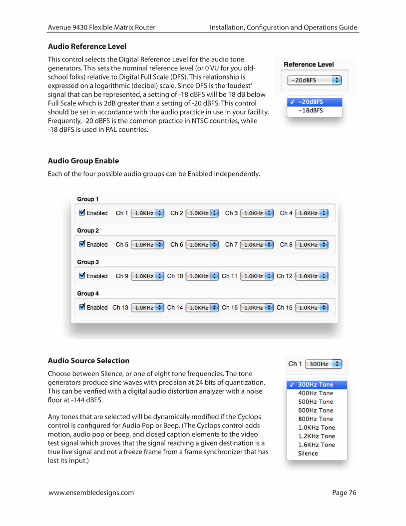
www.ensembledesigns.com Page 76
Avenue 9430 Flexible Matrix Router Installation, Configuration and Operations Guide
Audio Reference Level
This control selects the Digital Reference Level for the audio tone generators. This sets the nominal reference level (or 0 VU for you old-school folks) relative to Digital Full Scale (DFS). This relationship is expressed on a logarithmic (decibel) scale. Since DFS is the ‘loudest’ signal that can be represented, a setting of -18 dBFS will be 18 dB below Full Scale which is 2dB greater than a setting of -20 dBFS. This control should be set in accordance with the audio practice in use in your facility. Frequently, -20 dBFS is the common practice in NTSC countries, while -18 dBFS is used in PAL countries.
Audio Source Selection
Choose between Silence, or one of eight tone frequencies. The tone generators produce sine waves with precision at 24 bits of quantization. This can be verified with a digital audio distortion analyzer with a noise floor at -144 dBFS.
Any tones that are selected will be dynamically modified if the Cyclops control is configured for Audio Pop or Beep. (The Cyclops control adds motion, audio pop or beep, and closed caption elements to the video test signal which proves that the signal reaching a given destination is a true live signal and not a freeze frame from a frame synchronizer that has lost its input.)
Audio Group Enable
Each of the four possible audio groups can be Enabled independently.

www.ensembledesigns.com Page 77
Avenue 9430 Flexible Matrix Router Installation, Configuration and Operations Guide
Slate Text
Enter the desired Slate text in this field, then hit the Tab key or click outside of the Slate Text field. As with all of the configuration settings in the Router, this will be saved in non-volatile memory so that it persists when the Router is powered down. The text entered in this field is not lost when the Slate Enable is turned off.
Cyclops
In order to produce a dynamic, constantly changing Test Pattern, enable one of the Cyclops modes to affect the picture, sound or both. The Cyclops feature adds a motion element which is overlaid over the test pattern video. It is located below the Slate field. The white cyclops pulse continuously sweeps horizontally back and forth in its black window. At the left and right extremes of its excursion the pulse makes a one frame bright flash.
Slate Enable
When enabled, the text which has been entered in the Slate Text field will appear over top of the test pattern.
Meanwhile, the Beep/Pop feature will add variety to the tones carried by the embedded audio. Selecting Beep will produce a short beep (and is otherwise silent), while Pop momentarily takes the selected tone to silence. Industry practice identifies odd numbered channels as carrying Left content, and even numbered channels as the Right half of a stereo program. The Pop and Beep timing in the audio follows this convention, with the odd channels being marked when the Cyclops makes its left flash, and the even channels marked when the right edge flash occurs. Further, the ‘left’ channel is a single Beep/Pop, while the ‘right’ channel is a double Beep/Pop. This allows left/right identification even after the audio has been disembedded (demultiplexed) and has lost the implied channel association.
These aural and visual markers provide proof at downstream points in a transmission chain that it is producing live, uninterrupted delivery of content – even when not in active service. The precise synchronization between the visual Cyclops and the aural Beep/Pop are also useful to verify sound/picture lip-sync.
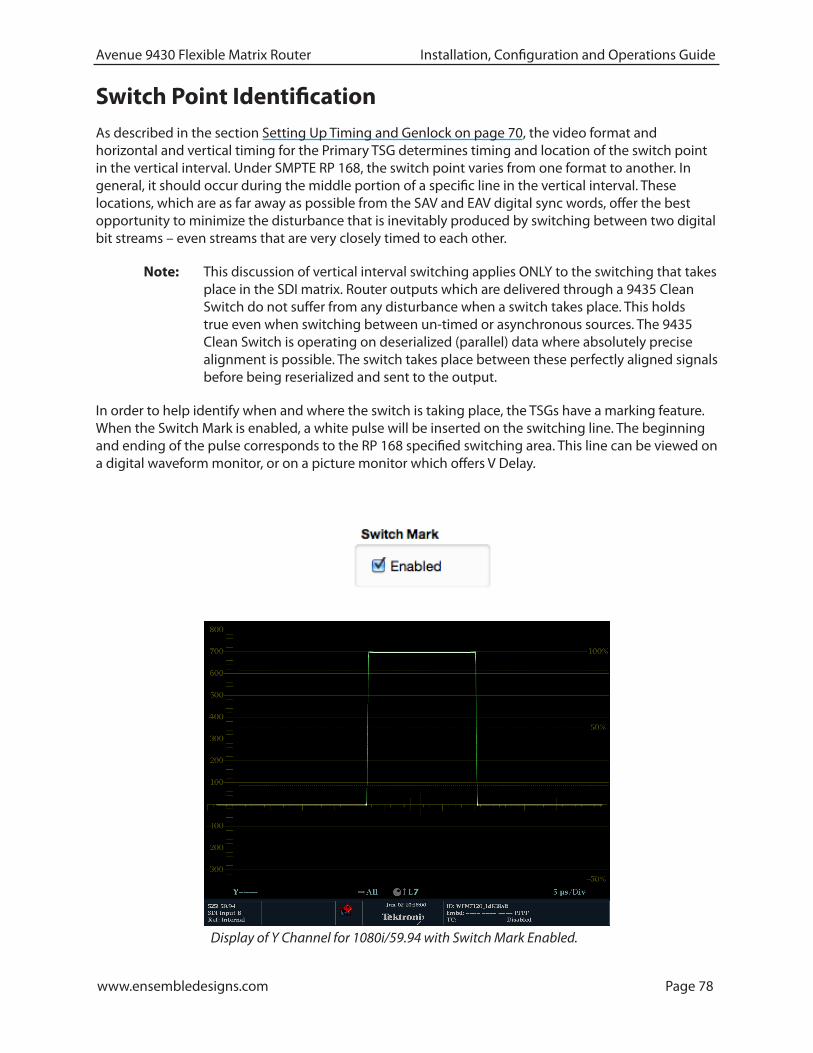
www.ensembledesigns.com Page 78
Avenue 9430 Flexible Matrix Router Installation, Configuration and Operations Guide
Switch Point IdentificationAs described in the section Setting Up Timing and Genlock on page 70, the video format and horizontal and vertical timing for the Primary TSG determines timing and location of the switch point in the vertical interval. Under SMPTE RP 168, the switch point varies from one format to another. In general, it should occur during the middle portion of a specific line in the vertical interval. These locations, which are as far away as possible from the SAV and EAV digital sync words, offer the best opportunity to minimize the disturbance that is inevitably produced by switching between two digital bit streams – even streams that are very closely timed to each other.
Note: This discussion of vertical interval switching applies ONLY to the switching that takes place in the SDI matrix. Router outputs which are delivered through a 9435 Clean Switch do not suffer from any disturbance when a switch takes place. This holds true even when switching between un-timed or asynchronous sources. The 9435 Clean Switch is operating on deserialized (parallel) data where absolutely precise alignment is possible. The switch takes place between these perfectly aligned signals before being reserialized and sent to the output.
In order to help identify when and where the switch is taking place, the TSGs have a marking feature. When the Switch Mark is enabled, a white pulse will be inserted on the switching line. The beginning and ending of the pulse corresponds to the RP 168 specified switching area. This line can be viewed on a digital waveform monitor, or on a picture monitor which offers V Delay.
Display of Y Channel for 1080i/59.94 with Switch Mark Enabled.

www.ensembledesigns.com Page 79
Avenue 9430 Flexible Matrix Router Installation, Configuration and Operations Guide
When switching away from the TSG output with Switch Mark to a source without, there will be a momentary frame where the switching discontinuity will be visible.

www.ensembledesigns.com Page 80
Avenue 9430 Flexible Matrix Router Installation, Configuration and Operations Guide
Working with the Clean Switch OptionEach 9435 Dual Clean Switch Option provides two, independent Frame sync/Clean Switches. These resources can be deployed within the Router in a variety of ways. The physical location of the submodule, whether installed on the 9430 core module, or on the 9440 in Expansion 1 position (the left hand position as viewed from the front of the frame) does not affect where or how each of these resources are assigned or used.
Note: Only a 9440 in the Expansion 1 position supports the 9435 Dual Clean Switch. Although it is mechanically possible to install a 9435 on a 9440 in Expansion 2, that 9435 will not appear as a resource in the configuration menus.
Clean Switch!/ Framesync
In OutGenlock
9435!/12
A Clean Switch is a Frame sync whose input and output can be connected to different points within the Router. The flexibility this provides allows the Clean Switch to be associated with either inputs or outputs.
The output side of the Clean Switch is genlocked to the reference being used within the Router. This ensures that the output is stable regardless of the input signal. Not only does this ensure clean switching between un-timed and even asynchronous sources, it also guarantees a stable, Black output upon loss of input.
In parallel with the video processing, 16 channels of embedded audio are silently switched as well. Incoming audio is disembedded, sample rate converted, switched, and then embedded into the output. The audio processing includes a delay mechanism to compensate for the delay imposed on the video by the frame sync. This compensation ensures that the time relationship (lip-sync) between audio and video is maintained.
The configuration of the Clean Switch includes its video format, timing, and embedded audio group enables.
When a Clean Switch is assigned to an output port, its input is fed from the routing matrix and it drives the output BNC connector. Any SDI source in the Router switched to this output will be presented synchronously and timed.

www.ensembledesigns.com Page 81
Avenue 9430 Flexible Matrix Router Installation, Configuration and Operations Guide
If an output port has been configured to Follow a Destination which has a Clean Switch assignment, that port will also deliver the Clean Switch output. That port set to Follow will not be seen as a destination on a control panel because there is still only one Destination.
The conceptual effect of this is to have incorporated an output DA (Distribution Amp) into the Router.

www.ensembledesigns.com Page 82
Avenue 9430 Flexible Matrix Router Installation, Configuration and Operations Guide
By assigning a Clean Switch to a Source (input port), it is fed from that port and its output drives the routing matrix.
This configuration is particularly useful with an asynchronous source. The frame sync feature of the Clean Switch means that this source will now be synchronous and timed on any output it is switched to.
This is essentially the same as placing an external frame sync upstream of that router input.
This technique can be further enhanced by the use of the Follow feature on an output port. When a port is assigned to follow a Source which has a Clean Switch assigned, the follow output will pick up the frame sync output, making the synchronized version of the signal available for external use independently of any signal switching within the routing matrix.

www.ensembledesigns.com Page 83
Avenue 9430 Flexible Matrix Router Installation, Configuration and Operations Guide
Clean Switch ConfigurationThere are four sets of configuration controls, one for each of the possible Clean Switches. Each Clean Switch is configured independently.
The Clean Switch configuration page
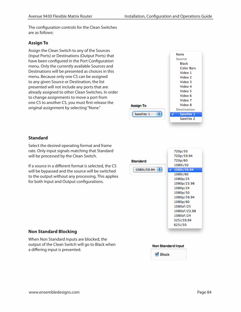
www.ensembledesigns.com Page 84
Avenue 9430 Flexible Matrix Router Installation, Configuration and Operations Guide
The configuration controls for the Clean Switches are as follows:
Assign To
Assign the Clean Switch to any of the Sources (Input Ports) or Destinations (Output Ports) that have been configured in the Port Configuration menu. Only the currently available Sources and Destinations will be presented as choices in this menu. Because only one CS can be assigned to any given Source or Destination, the list presented will not include any ports that are already assigned to other Clean Switches. In order to change assignments to move a port from one CS to another CS, you must first release the original assignment by selecting “None.”
Standard
Select the desired operating format and frame rate. Only input signals matching that Standard will be processed by the Clean Switch.
If a source in a different format is selected, the CS will be bypassed and the source will be switched to the output without any processing. This applies for both Input and Output configurations.
Non Standard Blocking
When Non Standard Inputs are blocked, the output of the Clean Switch will go to Black when a differing input is presented.
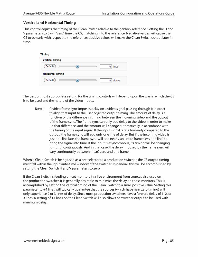
www.ensembledesigns.com Page 85
Avenue 9430 Flexible Matrix Router Installation, Configuration and Operations Guide
Vertical and Horizontal Timing
This control adjusts the timing of the Clean Switch relative to the genlock reference. Setting the H and V parameters to 0 will “zero” time the CS, matching it to the reference. Negative values will cause the CS to be early with respect to the reference; positive values will make the Clean Switch output later in time.
The best or most appropriate setting for the timing controls will depend upon the way in which the CS is to be used and the nature of the video inputs.
Note: A video frame sync imposes delay on a video signal passing through it in order to align that input to the user adjusted output timing. The amount of delay is a function of the difference in timing between the incoming video and the output of the frame sync. The frame sync can only add delay to the video in order to make up that difference, and the amount will change automatically in accordance with the timing of the input signal. If the input signal is one line early compared to the output, the frame sync will add only one line of delay. But if the incoming video is just one line late, the frame sync will add nearly an entire frame (less one line) to bring the signal into time. If the input is asynchronous, its timing will be changing (drifting) continuously. And in that case, the delay imposed by the frame sync will vary continuously between (near) zero and one frame.
When a Clean Switch is being used as a pre-selector to a production switcher, the CS output timing must fall within the input auto-time window of the switcher. In general, this will be accomplished by setting the Clean Switch H and V parameters to zero.
If the Clean Switch is feeding on-set monitors in a live environment from sources also used on the production switcher, it is generally desirable to minimize the delay on those monitors. This is accomplished by setting the Vertical timing of the Clean Switch to a small positive value. Setting this parameter to +4 lines will typically guarantee that the sources (which have near zero timing) will only experience 2 or 3 lines of delay. Since most production switchers have a forward delay of 1, 2, or 3 lines, a setting of +4 lines on the Clean Switch will also allow the switcher output to be used with minimum delay.

www.ensembledesigns.com Page 86
Avenue 9430 Flexible Matrix Router Installation, Configuration and Operations Guide
Audio Embed
The Clean Switch supports 16 channels (four groups) of embedded audio. In order for the Clean Switch output to have a consistent configuration of audio, regardless of what is present on the input, individual enables are provided for each group.
The Clean Switch output will always contain the enabled groups, but channels that are not present in the input will simply be silent. In this way, switching between sources with differing audio configurations will produce smooth, silent transitions.

www.ensembledesigns.com Page 87
Avenue 9430 Flexible Matrix Router Installation, Configuration and Operations Guide
Chapter 5: Operations and Step-by-Step ProceduresIn this ChapterThis chapter provides complete step-by-step procedures for each task that you can perform with the Router using the following control choices:
• Router Control Panel (5830) Operation
• Router Operation with the Web Browser Interface
You can use the web browser interface on a computer or on an iPad.
For serial protocols through TCP/IP, RS-232 and SNMP, please see Chapter 6: External Control on page 96.
Router Control Panel (5830) Operation
Orientation of Front PanelThe Router Control Panel has an LCD Display on the left. The two small round buttons to the left of the LCD Display are used for accessing ancillary data.
By default, the top row of buttons is used for Sources and illuminates red, while the bottom row of buttons is used for Destinations and lluminates green. However, if more than 16 Sources are being used, the buttons in the lower row can be used for Sources and will illuminate red as needed. Similarly, if more than 16 Destinations are being used, the buttons in the upper row can be used for Destinations and will illuminate green as needed.
The Direct and Take buttons are on the far right side of the front panel. The Direct button is on top; the Take button is on the bottom.
Performing Takes with the Router Control PanelWhile performing a take is a straight forward task, it can be done using more than one method.
To Perform a Take by Selecting a Source and a Destination
1. Select a Source by pressing one of the red Source buttons. The button illuminates more brightly to indicate that it is selected. The LCD display shows the realtime video thumbnail image of the Source you selected so that you can visually verify the content.
2. Select a Destination by pressing one of the green Destination buttons. The button illuminates more brightly to indicate that it is selected. As soon as you have selected both a Source and a Destination, the blue Take button, located in the lower right part of the router control panel, illuminates, indicating that the Router is ready for a Take.
3. Press the Take button. Your chosen Source is routed to the Destination that you selected. The LCD display continues to show the realtime video thumbnail image that is currently being routed to your chosen Destination. The Take button is no longer illuminated.

www.ensembledesigns.com Page 88
Avenue 9430 Flexible Matrix Router Installation, Configuration and Operations Guide
To Perform a Take by Selecting Only a New Source
As long as the Destination that you want is already selected, you can perform a Take by selecting a new Source, then pressing the Take button.
1. Leaving the Destination selection unchanged, select a new Source. The Source button illuminates to indicate that it is selected. The LCD display shows the real time video thumbnail image of the Source you selected so that you can visually verify the content.
2. Press the Take button. Your newly selected Source is now routed to the Destination. The LCD display continues to show the real time video thumbnail image that is currently being routed to your chosen Destination. The Take button is no longer illuminated.
Performing Direct Takes with the Router Control PanelIn Direct Take mode, you leave the same Destination selected while choosing a series of different Sources. There is no need to press the Take button when in Direct Take mode.
To Perform a Direct Take
1. Press the Direct button in the upper far right area of the router control panel. The Direct button illuminates to indicate that it is active.
2. Press a Destination button.
3. Press a Source button. The Destination immediately reflects your newly selected Source.
As long as you remain in Direct Take mode, you can continue to change Sources for the same Destination by pressing one Source button at a time in sequence.
To Exit Direct Take Mode
Press the Direct button in the upper far right area of the router control panel. The Direct button is no longer illuminated.
Accessing Ancillary Data with the Router Control PanelFor each video source, the Router detects and measures key parameters such as synchronicity, timing, line and frame rate, embedded audio presence/absence, closed caption information, and timecode data.
To Access Ancillary Data
For the Source currently showing in the LCD display, use the two small buttons located to the left of the LCD to navigate among the screens that show ancillary data. There are three ancillary data screens. Use either button to navigate among these screens.

www.ensembledesigns.com Page 89
Avenue 9430 Flexible Matrix Router Installation, Configuration and Operations Guide
Router Operation with the Web Browser InterfaceYou can control the Router through its web browser user interface. You can perform takes, direct takes, gang, and gang combined with direct takes.
PrerequisitesBefore you can access the Router through a web browser, you need to have access to an authenticated Control Point and the Router’s IP address. For further details about these requirements, please see the following sections:
• Assigning the Router a New IP Address on page 45
• Establishing Control Points and Access Authentication on page 63
• First Method: Requesting Access from a Control Point on page 68
Accessing the Web Browser Control InterfaceTo access the web browser control interface, enter the Router’s IP address into the browser’s address bar. The Router’s interface displays, showing Sources in the upper area and Destinations in the lower area.
The Web Browser Interface
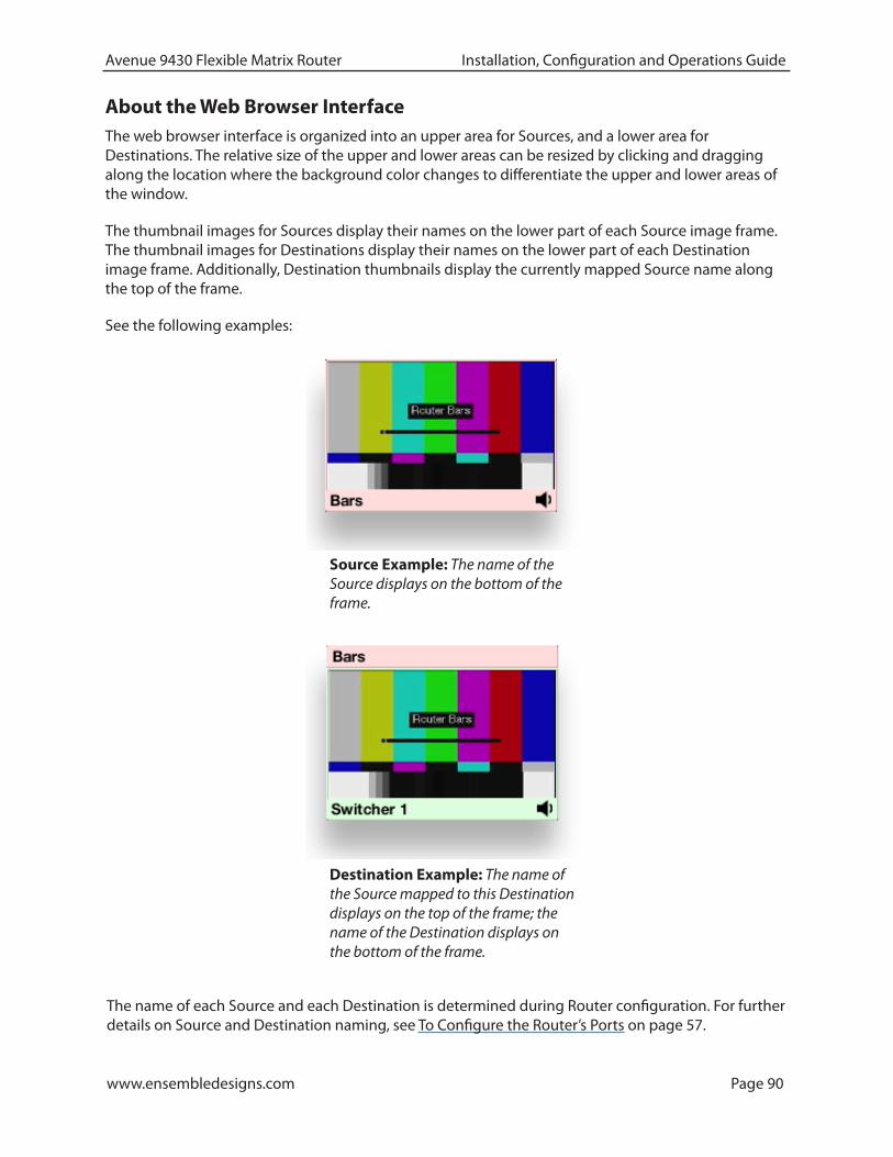
www.ensembledesigns.com Page 90
Avenue 9430 Flexible Matrix Router Installation, Configuration and Operations Guide
About the Web Browser InterfaceThe web browser interface is organized into an upper area for Sources, and a lower area for Destinations. The relative size of the upper and lower areas can be resized by clicking and dragging along the location where the background color changes to differentiate the upper and lower areas of the window.
The thumbnail images for Sources display their names on the lower part of each Source image frame. The thumbnail images for Destinations display their names on the lower part of each Destination image frame. Additionally, Destination thumbnails display the currently mapped Source name along the top of the frame.
See the following examples:
Source Example: The name of the Source displays on the bottom of the frame.
Destination Example: The name of the Source mapped to this Destination displays on the top of the frame; the name of the Destination displays on the bottom of the frame.
The name of each Source and each Destination is determined during Router configuration. For further details on Source and Destination naming, see To Configure the Router’s Ports on page 57.

www.ensembledesigns.com Page 91
Avenue 9430 Flexible Matrix Router Installation, Configuration and Operations Guide
PreferencesUse the Preferences button, located in the upper right area of the browser window, to customize how the thumbnail images display. Sources and Destinations can be sized independently. Choose from small, medium and large.
For Sources, you can also choose to display ancillary data next to each thumbnail or instead of each thumbnail. It is the same ancillary data that is available through the LCD display of the Router Control Panel (5830).
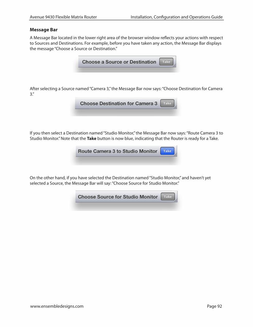
www.ensembledesigns.com Page 92
Avenue 9430 Flexible Matrix Router Installation, Configuration and Operations Guide
Message Bar
A Message Bar located in the lower right area of the browser window reflects your actions with respect to Sources and Destinations. For example, before you have taken any action, the Message Bar displays the message “Choose a Source or Destination.”
After selecting a Source named “Camera 3,” the Message Bar now says: “Choose Destination for Camera 3.”
If you then select a Destination named “Studio Monitor,” the Message Bar now says: “Route Camera 3 to Studio Monitor.” Note that the Take button is now blue, indicating that the Router is ready for a Take.
On the other hand, if you have selected the Destination named “Studio Monitor,” and haven’t yet selected a Source, the Message Bar will say: “Choose Source for Studio Monitor.”

www.ensembledesigns.com Page 93
Avenue 9430 Flexible Matrix Router Installation, Configuration and Operations Guide
Performing Takes with a Web BrowserWhile performing a take is a straight forward task, it can be done using more than one method.
To Perform a Take by Selecting a Source and a Destination
1. Select a Source by clicking one of the Source thumbnail images. The thumbnail frame turns red to indicate that it is selected.
2. Select a Destination by clicking one of the Destination thumbnail images. The thumbnail frame turns green to indicate that it is selected. As soon as you have selected both a Source and a Destination, the Take button turns blue, indicating that the Router is ready for a Take.
3. Click Take in the lower right area of the web browser. Your chosen Source is routed to the Destination you selected. The Destination thumbnail image updates to reflect your currently selected Source. The Take button is now greyed out.
To Perform a Take by Selecting Only a New Source
As long as the Destination that you want is already selected, you can do a Take by selecting a new Source, then clicking Take.
1. Leaving the Destination selection unchanged, select a new Source.
2. Click Take. Your chosen Source is routed to the Destination. The Destination thumbnail image updates to reflect your new Source selection.

www.ensembledesigns.com Page 94
Avenue 9430 Flexible Matrix Router Installation, Configuration and Operations Guide
Performing Direct Takes with a Web BrowserIn Direct Take mode, you leave the same Destination selected while selecting different Sources with only one click. There is no need to click the Take button when in Direct Take mode.
To Perform a Direct Take
1. Click Direct in the lower left area of the browser window. The Direct button turns orange.
2. Select a Destination.
3. Select a Source. The Source is immediately routed to the Destination. The Destination thumbnail image reflects your newly selected Source.
As long as you remain in Direct Take mode, you can continue to change Sources for the same Destination with only one click.
To Exit Direct Take Mode
Click Direct in the lower left area of the browser window. The Direct button is now greyed out, indicating that you are no longer in Direct Take mode.

www.ensembledesigns.com Page 95
Avenue 9430 Flexible Matrix Router Installation, Configuration and Operations Guide
Performing Gang Takes with a Web BrowserGang Takes involve routing one Source at a time to a set of Destinations.
To Perform a Gang Take
1. Click Gang in the lower left area of the browser window. The Gang button turns orange.
2. Select a Source by clicking one of the Source thumbnail images. The thumbnail frame turns red to indicate that it is selected.
3. Select a set of Destinations by clicking multiple Destination thumbnail images sequentially. The first thumbnail frame you select turns green; the remaining thumbnails you select turn yellow.
4. Click Take in the lower right area of the web browser. The Source is routed to the set of Destinations. The set of selected Destination thumbnail images updates to reflect your selected Source. The Take button is now greyed out.
You can continue to perform gang takes in this manner as long as you are in Gang mode.
To Exit Gang Mode
Click Gang in the lower left area of the browser window. The Gang button is now greyed out, indicating that you are no longer in Gang Mode.
Performing Direct Gang Takes with a Web BrowserDirect Gang Takes involve routing one Source at a time to a set of Destinations instantaneously, without having to use the Take button.
To Perform a Direct Gang Take
1. Click Direct in the lower left area of the browser window. The Direct button turns orange.
2. Click Gang in the lower left area of the browser window. The Gang button turns orange.
3. Select a set of Destinations by clicking multiple Destination thumbnail images sequentially. The first thumbnail frame you select turns green; the remaining thumbnails you select turn yellow.
4. Select a Source by clicking one of the Source thumbnail images. The Source is routed to the set of Destinations. The set of selected Destination thumbnail images updates to reflect your selected Source.
To Exit Direct Gang Mode
Click Direct and Gang in the lower left area of the browser window. The Direct and Gang buttons are now greyed out, indicating that you are no longer in Direct Gang Mode.
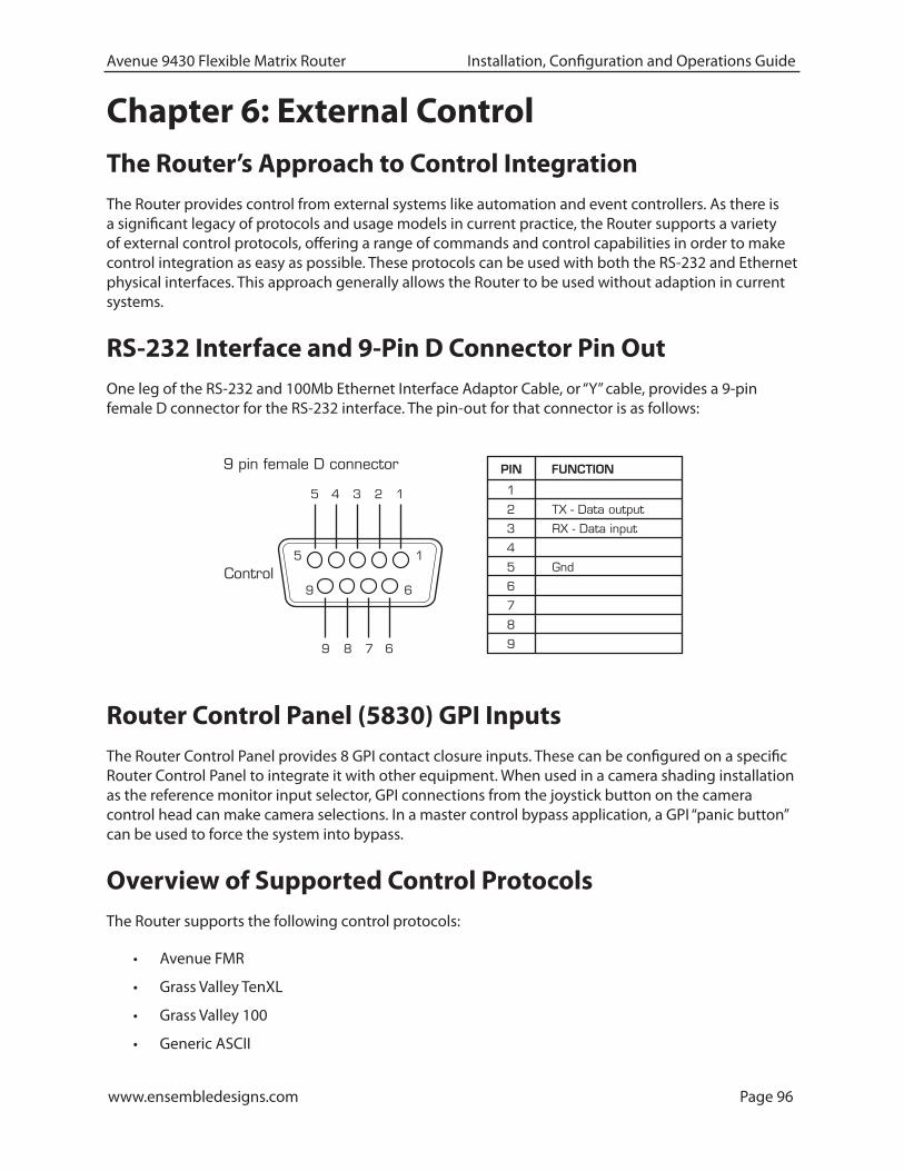
www.ensembledesigns.com Page 96
Avenue 9430 Flexible Matrix Router Installation, Configuration and Operations Guide
Chapter 6: External ControlThe Router’s Approach to Control IntegrationThe Router provides control from external systems like automation and event controllers. As there is a significant legacy of protocols and usage models in current practice, the Router supports a variety of external control protocols, offering a range of commands and control capabilities in order to make control integration as easy as possible. These protocols can be used with both the RS-232 and Ethernet physical interfaces. This approach generally allows the Router to be used without adaption in current systems.
RS-232 Interface and 9-Pin D Connector Pin OutOne leg of the RS-232 and 100Mb Ethernet Interface Adaptor Cable, or “Y” cable, provides a 9-pin female D connector for the RS-232 interface. The pin-out for that connector is as follows:
Router Control Panel (5830) GPI InputsThe Router Control Panel provides 8 GPI contact closure inputs. These can be configured on a specific Router Control Panel to integrate it with other equipment. When used in a camera shading installation as the reference monitor input selector, GPI connections from the joystick button on the camera control head can make camera selections. In a master control bypass application, a GPI “panic button” can be used to force the system into bypass.
Overview of Supported Control ProtocolsThe Router supports the following control protocols:
• Avenue FMR
• Grass Valley TenXL
• Grass Valley 100
• Generic ASCII
PIN FUNCTION
1
1
6
5
8
9Control
2 TX - Data output
3 RX - Data input
4
5 Gnd
6
7
8
9
15 4 3 2
9 7 6
9 pin female D connector
www.ensembledesigns.com Page 97
Avenue 9430 Flexible Matrix Router Installation, Configuration and Operations Guide
• RS-232
• Telnet
• TCP/IP
These control protocols are briefly described below. For detailed documentation of the automation protocols, please see “Appendix A: Automation Protocols” on page 105.
Avenue FMRUnique to the Avenue 9430/9440 Flexible Matrix Router, this is an ASCII (human readable) control protocol with an extensive command set, offering very useful and powerful external control functionality. These interfaces are enabled, disabled and configured through the External Control tab on the web configuration tool.
Simultaneous Support for Multiple Protocols
These protocols are accessible over three different interfaces. Each interface is independent, allowing simultaneous support for different protocols on different interfaces.
Control Profiles for External Interfaces
An interface is “connected” to the Router through a Control Profile – similar to a physical control panel. This allows for the choice of available Sources and Destinations, and the order in which they are mapped to the interface protocol to be customized on the Router rather than on the controlling device.
Grass Valley TenXLThe Router supports both the ASCII (human readable) and SMPTE ESbus (binary) variants of this protocol. Supports only source to destination control.
Grass Valley 100The Router supports SMPTE ESbus with and without the “break” character requirement. Though widely implemented, this protocol is limited in usefulness with a router because it supports only 4 output busses. Supports only source to destination control.
Generic ASCIIThe Router supports this simple human readable protocol with both space and comma variable separators. Supports source to destination routing and salvos.
RS-232The conventional RS-232 serial interface is provided from the 9430 module through the control breakout cable. This interface can operate from 1200 to 115,200 baud (bits per second).
TelnetUsing the Ethernet port on the control breakout cable, you can open a Unix-style Telnet session with the 9430 module. As a text-oriented communications facility, Telnet is only suited to ASCII protocols. It provides easy access from a distance (even a great distance) and can be of particular utility for system

www.ensembledesigns.com Page 98
Avenue 9430 Flexible Matrix Router Installation, Configuration and Operations Guide
debugging. If the Telnet interface is disabled in the External Control configuration, the 9430 will refuse the connection.
TCP/IPYou can open a TCP/IP session at a private port number (to be specified) to enable network control. As with Telnet, this interface must be enabled in the External Control configuration in order for the 9430 to accept the connection. This is the preferred network equivalent to RS-232 and it works with both ASCII and binary protocols and command sets.
Additional GPI and Serial Connections through JL Cooper eBOXAdditional GPI and Serial connections for the Router can be made through the JLCooper eBOX, a third-party device. It provides 24 GPI inputs, 24 GPI outputs and 4 serial connectors. Please see Using the JL Cooper eBOX with Ensemble Designs Avenue Equipment for a detailed description of the process of configuring the Router for GPIO (general purpose input/output) functionality using the eBOX.
SNMP InterfaceA Simple Network Management Protocol (SNMP) agent in the 9430 supports Control and Status queries from an SNMP manager.
Programming Reference DocumentThe Management Information Base (MIB) document, specific to the Router, is a required programming reference while customizing the SNMP manager. You can either download the MIB document directly from the Router’s web interface or request it from Ensemble Designs.
The SNMP interface will be active only if enabled through External Control configuration. SNMP support will not be available on initial product shipments, but will be provided by a subsequent system software upgrade.
Software Development Kit (SDK)When control requirements go beyond straight forward functions, such as source to destination routing and salvo execution, you may need to develop an interface more specific to your needs. To that end, Ensemble Designs will be releasing an interface design guide, or software development kit (SDK), to support such efforts.
Accessing Features Unique to the 9430 Flexible Matrix RouterThat more extensive interface will be necessary when you need to access features unique to the Flexible Matrix Router, such as:
• reading the input signal metadata;
• controlling the internal TSGs; and
• capturing video thumbnails remotely
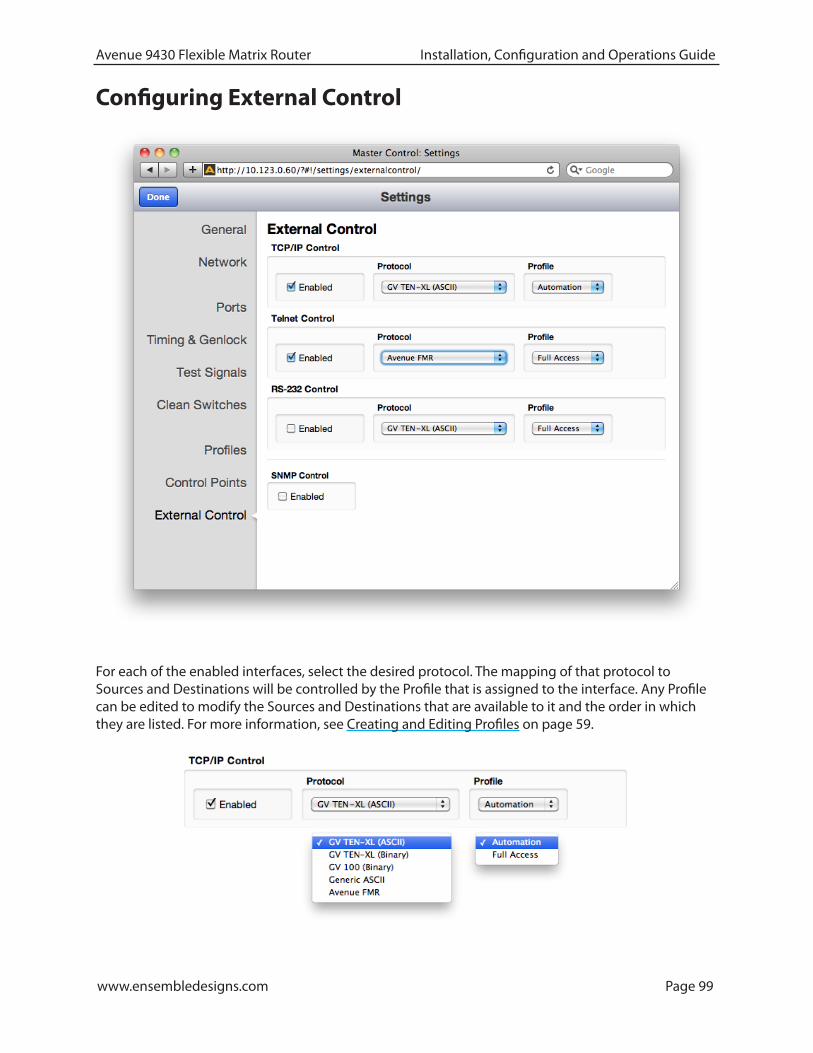
www.ensembledesigns.com Page 99
Avenue 9430 Flexible Matrix Router Installation, Configuration and Operations Guide
Configuring External Control
For each of the enabled interfaces, select the desired protocol. The mapping of that protocol to Sources and Destinations will be controlled by the Profile that is assigned to the interface. Any Profile can be edited to modify the Sources and Destinations that are available to it and the order in which they are listed. For more information, see Creating and Editing Profiles on page 59.
www.ensembledesigns.com Page 100
Avenue 9430 Flexible Matrix Router Installation, Configuration and Operations Guide
Chapter 7: Maintenance and TroubleshootingThis chapter addresses certain known issues and possible issues that new users may encounter while becoming familiar with using the Flexible Matrix Router.
Troubleshooting the Router Module (9430)
Cannot Connect to the RouterIf you are having difficulty connecting to the Router, check that the IP addresses of the Router and the computer or device are not in conflict. Check also that the cabling is correct.
• Review the instructions in Initially Connecting to the Router on page 40 to make sure you have configured the IP addresses correctly.
• See also Router Control Connections on page 32 to make sure you have correctly cabled the control connections between the Router and the controlling computer.
Router Not Running
To Determine if the Router is Running
Open the front door of the Avenue frame and check the Run light on the front panel of the 9430. When the Router is running properly, the Run light will be blinking on and off. Note that the rate of blinking will not match the rate of blinking of the Run lights of other modules running in the Avenue frame. However, if the Run light stops blinking, whether it remains on or off, it means that the Router has stopped.
Resetting the RouterThere are two types of resets for the 9430. One is a reboot. The other is a reset to the factory default settings.
Rebooting
To reboot the 9430, use something with a fine point, such as a paperclip, to press into the small “Reset” hole on the lower part of the front panel. Press once briefly and release. The module will reboot. A reboot typically takes a few minutes. After the reboot is complete, the Run light will resume blinking.
Resetting to Factory Default Settings
If you want to reset your module to factory default settings, use something with a fine point, such as a paperclip, to press and hold into the small “Reset” hole on the lower part of the front panel. Continue holding the Reset button in its pressed in position until you see all of the Input lights on the front panel illuminate several times (approximately 15 seconds), then release. The 9430 will reboot with factory default settings. Note that the IP address and all other settings will have to be reconfigured.
Authorized Control Point Unable to Connect to RouterIf you are using an authorized Control Point but you are seeing the message “Control Point Disabled,” check to make sure that the Control Point has been assigned a Profile. Without an assigned Profile, it is

www.ensembledesigns.com Page 101
Avenue 9430 Flexible Matrix Router Installation, Configuration and Operations Guide
expected behavior that you would see the message “Control Point Disabled.”
Please see Creating and Editing Profiles on page 59 and Establishing Control Points and Access Authentication on page 63 for more details on this issue.
Troubleshooting the Router Control Panel (5830)
Router Control Panel has Lost its Connection to the RouterIf the Router Control Panel becomes unresponsive or loses its communication with the Router, there are two methods for resetting it.
Rebooting the Router Control Panel
To reboot the 5830, use something with a fine point, such as a paperclip, to press into the small “Reset” hole on the back of the Router Control Panel. Press once briefly and release. The unit will reboot. A reboot typically takes a few minutes. After the reboot is complete, the Router Control Panel should re-establish its connection to the Router.
Resetting the Router Control Panel to Factory Default Settings
If you want to reset your 5830 to factory default settings, use something with a fine point, such as a paperclip, to press and hold into the small “Reset” hole on the back of the Router Control Panel. Continue holding the Reset button in its pressed in position for approximately 15 seconds, then release. The 5830 will reboot with factory default settings. Note that the IP address and all other settings will have to be reconfigured.
Configuration Changes are not Taking EffectAfter making changes to configuration settings, make sure you are doing two things:
• Click the Save Changes button
• Click the Done button
If you save changes without also clicking Done, the changes may not be implemented.
Troubleshooting the Web Browser Control UI
If the Take Button is Grayed OutIf the Take button is blue, it means that a Take is possible. If the Take button is grayed out, then no Take can be done without first selecting both a Source and a Destination. If a Source and a Destination you want are already selected, you do not need to select one again.
Supported BrowsersThe Router supports current versions of the following browsers for Mac and PC:
• Safari (version 5 or later)
• Firefox (version12 or later)
• Chrome (version 17 or later)

www.ensembledesigns.com Page 102
Avenue 9430 Flexible Matrix Router Installation, Configuration and Operations Guide
• Internet Explorer (version 9 or later)
Enabling cookies is required for all browsers.
Software Updating
Download Current Software
Download the current software for the 9430 to your PC or Mac from the following URL:
http://www.ensembledesigns.com/support/avenue-support/avenue-software
Navigate to your 9430 Module through a Web Browser
From the controlling computer, navigate to the IP address of your 9430 from a web browser. The Router view displays.
From the upper left area of the web page, select Settings. The Settings > General window displays.
Update the Module Software
From the Settings > General window, under the Software Update heading, click the Choose File button. From the navigation dialog window, navigate to the updated software file that you downloaded to your computer. Select the downloaded software, then click the Start Update button. The Updating Firmware window displays. The updating process can take several minutes.
Warranty and Factory ServiceThis module is covered by a five year limited warranty. If you require service (under warranty or not), please contact Ensemble Designs and ask for customer service before you return the unit. This will allow the service technician to provide any other suggestions for identifying the problem and recommending possible solutions.
If you return equipment for repair, please get a Return Material Authorization Number (RMA) from the factory first.
tel +1 530.478.1830 fax +1 530.478.1832 [email protected] www.ensembledesigns.com Ship the product and a written description of the problem to:
Ensemble Designs, Inc. Attention: Customer Service RMA ##### 870 Gold Flat Rd. Nevada City, CA 95959 USA
Be sure to put your RMA number on the outside of the box.

www.ensembledesigns.com Page 103
Avenue 9430 Flexible Matrix Router Installation, Configuration and Operations Guide
Specifications9430Inputs Number Eight Signal Type HD Serial Digital 1.485 Gb/s, SMPTE 274M, 292M or 296M HD Serial Digital 2.97 Gb/s, SMPTE 424M, 425M SD Serial Digital 270 Mb/s, SMPTE 259M DVB-ASI at 270 Mb/s, SMPTE 310M AES3id Impedance 75Ω Return Loss >15dB to 1.485 GHz
Max Cable Length 270 Mb/s 300 meters Belden 1694A 1.485 Gb/s 100 meters Belden 1694A 2.97 Gb/s 70 meters Belden 1694A Automatic Cable EQ
Outputs Number Two Signal Type Follows input Impedance 75Ω Return Loss >15dB to 1.485 GHz Output DC None (AC coupled)
Reference Number One via frame master ref input Signal Type Composite black, Tri-Level Sync, 10 MHz
Standards Supported 1080i 50, 59.94 or 60 Hz, SMPTE 274M -4,5,6 720p 50, 59.94 or 60 Hz, SMPTE 296M -1,2,3 1080p 23.98, 24 or 25 Hz, SMPTE 274M -9,10,11 1080p 50, 59.94, 60 Hz, SMPTE 424M, 425M Level A, Level B (9435 Level A only) 1080sF 23.98, 24 or 25 Hz, RP211 -14,15,16 625i 50 525i 59.94

www.ensembledesigns.com Page 104
Avenue 9430 Flexible Matrix Router Installation, Configuration and Operations Guide
9440Inputs Number Up to ten, user configurable Signal Type Same as 9430 Impedance 75Ω Return Loss >15dB to 1.485 GHz
Outputs Number Up to ten, user configurable Signal Type Follows input Impedance 75Ω Return Loss >15dB to 1.485 GHz Output DC None (AC coupled)

www.ensembledesigns.com Page 105
Avenue 9430 Flexible Matrix Router Installation, Configuration and Operations Guide
Appendix A: Automation ProtocolsRevision 1.1
1 IntroductionThis appendix describes the various communication protocols available in the 9430 Flexible Matrix Router to support external control by an automation system. It also discusses the various means for connecting an external controller to the router.
The intended audience is the developer tasked with connecting an external control device to the router.
Some discussion of configuration of the 9430 router is covered in this document, but only as it pertains to attaching an external control device. It is recommended that the reader be familiar with general router configuration procedures as described earlier in this manual.
2 ConventionsThis section describes the conventions used in this appendix.
• A number followed by the letter “H” is a hexadecimal number. E.g., 12H is the hexadecimal equivalent of decimal 18.
• Command syntax in this appendix is described using a notation similar to BNF (Backus-Naur Form).
<symbol> A symbol is represented by the symbol name inside of arrow brackets ‘<’ and ‘>’.
[optional] Optional parts are shown inside of square brackets.
… Items that can be repeated are indicated by an ellipse.
literals Characters, numbers, and strings of text that are not part of a symbol are to be interpreted literally. They would be typed exactly as they are shown.
‘>’ Single quotes may be used in certain cases to avoid ambiguity when a character needs to be typed literally. For example, since the arrow bracket is normally used to indicate a symbol, enclosing it in single quotes means it should be interpreted literally as the arrow bracket character. In this case it should be typed as a single character (without the quotes).
www.ensembledesigns.com Page 106
Avenue 9430 Flexible Matrix Router Installation, Configuration and Operations Guide
Syntax Example:
@<Space>X:<Lvls>/<Dest>,<Src>[/<Dest>,<Src>…]<CR>
The symbols in the above example are <Space>, <Lvls>, <Dest>, <Src>, and <CR>. The meaning of symbols like these will be defined as they occur throughout this document.
The optional portion in the example (enclosed in square brackets), shows that an additional “/<Dest,<Src>” element may be present. It also indicates (with the ellipse character) that this optional element may occur repeatedly.
The following characters in the example are literals and should be typed as they appear (no quotes):
‘@’, ‘X’, ‘:’, ‘/’, and ‘,’
3 OverviewThe 9430 Flexible Matrix Router is a highly configurable router. The basic size is 8 inputs by 2 outputs (8x2). You can add up to two I/O Expansion Modules, each with 10 bi-directional ports. Each of these additional ports can be independently configured as an input or output. This permits easy configuration of the matrix into various symmetrical and asymmetrical geometries (28x2, 8x22, 15x15, and many sizes in between).
In addition to the configurability of the ports within the matrix, the presentation of these inputs and outputs to a control point (e.g., control panel, web browser, automation system, etc.) is also configurable. This presentation is managed through a Profile—a map of the sources (inputs) and destinations (outputs) that are available to a control point. The Profile also determines the order in which the sources and destinations appear. These Profiles thereby provide the flexibility for every control point to have its own view (or a shared view) of the organization of inputs and outputs. The use of Profiles to order the inputs and destinations is of particular interest for installations using automation systems. (For details, refer to “Understanding Profiles” on page 107 in this appendix.)
4 Before You BeginSome configuration of the 9430 Router will be required in order to control it from an external device such as an automation system.
In order to configure the router, you will need to establish an IP Address for the 9430 Router and browse to the 9430’s web page from a computer. The details for doing this are not covered in this appendix. Please refer to “Chapter 4: Configuration” earlier in this manual for instructions.

www.ensembledesigns.com Page 107
Avenue 9430 Flexible Matrix Router Installation, Configuration and Operations Guide
5 Understanding ProfilesAny device used to control the 9430 Router must be assigned a Profile.
A Profile provides a configured view of the sources and destinations in the router. It determines which sources and destinations are accessible by the device. It also defines the order of the sources and destinations as seen by the controlling device. This ordering feature is of particular interest for automation control because it provides a simple means to map sources and destinations to suit the automation system’s requirements.
An example will help illustrate how a Profile is used to connect an automation system to the router.
Note: It is assumed the reader is familiar with the methods for configuring input and output ports in the 9430 Router. For help with these topics, please refer to “Configuring the Router’s Ports” on page 54.
Assume that we have cabled up the router so that it has 4 inputs and 2 outputs. Table 1 lists the inputs and outputs connected to the router in this example.
Table 1
Router port number Src/Dest Name
Input Port 1 Network Feed
Input Port 2 Studio 3
Input Port 3 Server 6
Input Port 4 Server 4
Output Port 1 Microwave
Output Port 2 Transmitter
Suppose we want to access these inputs and outputs from an automation system and that we want to renumber the sources and destinations to fit the automation system’s numbering scheme. In Table 2 we have added a column to list the desired automation number associated with each input/output.
Table 2
Router port number Src/Dest Name Desired automation number
Input Port 1 Network Feed source # 7
Input Port 2 Studio 3 source # 5
Input Port 3 Server 6 source # 2
Input Port 4 Server 4 source # 3
Output Port 1 Microwave destination # 8
Output Port 2 Transmitter destination # 3
By rearranging the information in Table 2, we have produced a sorted list of sources and a sorted list of destinations for the automation system. The results are in Table 3 and Table 4.

www.ensembledesigns.com Page 108
Avenue 9430 Flexible Matrix Router Installation, Configuration and Operations Guide
Table 3
Desired automation Src number
Src Name Router port number
1 - -
2 Server 6 Input Port 3
3 Server 4 Input Port 4
4 - -
5 Studio 3 Input Port 2
6 - -
7 Network Feed Input Port 1
Table 4
Desired automation Dest number
Dest name Router port number
1 - -
2 - -
3 Transmitter Output Port 2
4 - -
5 - -
6 - -
7 - -
8 Microwave Output Port 1
Note: In this example, we are assuming a protocol that numbers sources and destinations beginning with the number 1. Some protocols begin numbering at zero (e.g., the Grass Valley TEN-XL ASCII Protocol and the Generic ASCII protocol).
We can now use these lists to create a Profile in the 9430 Router that numbers the sources and destinations to match the desired automation numbering scheme.
Using the 9430’s Profile Editor to arrange the order of the sources and destinations in their respective columns, and inserting spaces at the appropriate places, we can create a Profile with the numbering order that the automation system requires. The Profile to accomplish this is illustrated in Figure 1.

www.ensembledesigns.com Page 109
Avenue 9430 Flexible Matrix Router Installation, Configuration and Operations Guide
Figure 1
To change the number for a particular source or destination, simply edit the Profile and move the source or destination to its new position until the order produces the numbering scheme required by the automation system. For example, if Transmitter needs to be changed to destination 1, simply drag it to the top of the destination list in the Profile Editor and save the Profile.
For detailed instructions on how to create and edit Profiles, refer to “Creating and Editing Profiles” on page 59.
6 ConfigurationTo control the router from an external device such as an automation system, the router requires some configuration. To do this you will need to browse to the 9430’s web page from a computer. (Details for doing this are covered in “Initially Connecting to the Router” on page 40.)
After browsing to the 9430’s web page, click the gray button in the upper left part of the browser window to select System Settings. The General page will appear on the right side of the screen.
On the left side of the screen is the Navigation Panel. It is currently set to the General page. Use the Navigation Panel to select different areas of configuration.
www.ensembledesigns.com Page 110
Avenue 9430 Flexible Matrix Router Installation, Configuration and Operations Guide
6.1 Profile ConfigurationTo access the Profile Editor, select Profiles in the Navigation Panel.
Create or edit a Profile so the sources and destinations are in the order the automation system requires. Refer to the example discussed in Section 5, “Understanding Profiles,” in this appendix.
Note: The only sources and destinations that show up in the Profile Editor are those that have been previously defined in the Ports page. To view this page, select Ports in the Navigation Panel. Refer to “Configuring the Router’s Ports” on page 54 for information on defining ports.
6.2 External Control ConfigurationIn order to control the 9430 Router from an automation system or other external controller, specific configuration choices need to be made in the External Control Editor.
To access the External Control Editor, select External Control in the Navigation Panel.
6.2.1 Connection Mode
Choose the means of connecting the automation system to the router. The choices are TCP/IP, Telnet, or RS-232.
TCP/IP
To use TCP/IP with your automation system, check the Enable box in the TCP/IP Control section of the External Control page.
When using TCP/IP, the automation system will need to connect to Port 5200 at the 9430 Router’s IP address.
Telnet
To use Telnet with your automation system, check the Enable box in the Telnet Control section of the External Control page.
Telnet is by its nature a text-based communication method. As a result, this connection choice is only appropriate for ASCII-based protocols.
When using Telnet, the automation system will need to connect to Port 5100 at the 9430 Router’s IP address.
For security reasons the default Telnet port number has been disabled in the 9430 Router. Only Port 5100 is activated for Telnet use in the router and is strictly limited to use by automation systems using the protocols described in this document.

www.ensembledesigns.com Page 111
Avenue 9430 Flexible Matrix Router Installation, Configuration and Operations Guide
RS-232
The 9430 Router provides an RS-232 port for serial communications. The pin-out of the DB 9 serial connector used for this purpose is described in “Chapter 6: External Control” on page 96.
To connect to the router via the RS-232 port of your automation system, check the Enable box in the RS-232 Control section of the External Control page.
To use RS-232, you will need to set the following additional configuration items in the router:
Baud Rate
From the Baud Rate drop-down control, select the baud rate the automation system will use to communicate with the router. The 9430 Router supports the following baud rates for serial communication:
9600 19200 38400 115200
Data Bits
From the Data Bits drop-down control, select the number of data bits that will be transmitted per byte. The 9430 Router supports 7 or 8 data bits per byte for serial communication.
Stop Bits
From the Stop Bits drop-down control, select the number of stop bits that will be sent per byte. The 9430 Router supports 1 or 2 stop bits per byte for serial communication.
Parity
From the Parity drop-down control, select the desired parity setting. The 9430 Router supports odd, even, or no parity for serial communication.
www.ensembledesigns.com Page 112
Avenue 9430 Flexible Matrix Router Installation, Configuration and Operations Guide
6.2.2 Protocol Selection
From the Protocol drop-down control, select which protocol the router and automation system will use to communicate. The details of the various protocols are discussed in Section 7, “Protocols,” in this appendix.
6.2.3 Profile Selection
From the Profile drop-down control, select the Profile that will determine the automation numbering scheme. (If you have not set up a Profile, refer to Section 5, “Understanding Profiles,” in this appendix.)
7 ProtocolsThe 9430 Router supports multiple protocols to allow crosspoint switching from external controllers.
The supported protocols are these:
• GV TEN-XL ASCII Protocol
• GV Performer ASCII Protocol
• Generic ASCII Protocol
For installations that already support one of these protocols, choosing the same protocol can minimize programming changes to the automation system when installing the 9430 Router.
These protocols are presented in the subsections below.
7.1 GV TEN-XL ASCII ProtocolThe Grass Valley TEN-XL ASCII Protocol is a serial protocol used by TEN-XL Routing Switchers. For installations that already support this protocol, this is a good choice to minimize programming changes to the automation system.
The implementation of this protocol has been adapted as appropriate to reflect the features in the 9430 Router.
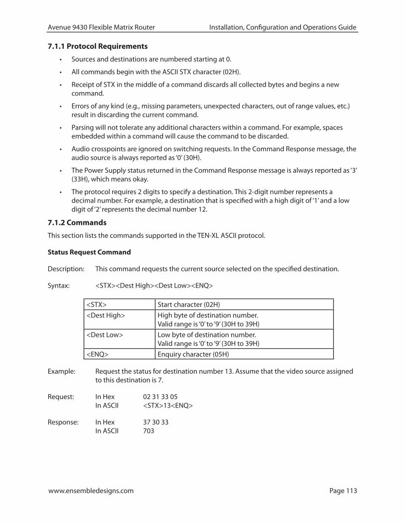
www.ensembledesigns.com Page 113
Avenue 9430 Flexible Matrix Router Installation, Configuration and Operations Guide
7.1.1 Protocol Requirements
• Sources and destinations are numbered starting at 0.
• All commands begin with the ASCII STX character (02H).
• Receipt of STX in the middle of a command discards all collected bytes and begins a new command.
• Errors of any kind (e.g., missing parameters, unexpected characters, out of range values, etc.) result in discarding the current command.
• Parsing will not tolerate any additional characters within a command. For example, spaces embedded within a command will cause the command to be discarded.
• Audio crosspoints are ignored on switching requests. In the Command Response message, the audio source is always reported as ‘0’ (30H).
• The Power Supply status returned in the Command Response message is always reported as ‘3’ (33H), which means okay.
• The protocol requires 2 digits to specify a destination. This 2-digit number represents a decimal number. For example, a destination that is specified with a high digit of ‘1’ and a low digit of ‘2’ represents the decimal number 12.
7.1.2 Commands
This section lists the commands supported in the TEN-XL ASCII protocol.
Status Request Command
Description: This command requests the current source selected on the specified destination.
Syntax: <STX><Dest High><Dest Low><ENQ>
<STX> Start character (02H)
<Dest High> High byte of destination number. Valid range is ‘0’ to ‘9’ (30H to 39H)
<Dest Low> Low byte of destination number. Valid range is ‘0’ to ‘9’ (30H to 39H)
<ENQ> Enquiry character (05H)
Example: Request the status for destination number 13. Assume that the video source assigned to this destination is 7.
Request: In Hex 02 31 33 05 In ASCII <STX>13<ENQ>
Response: In Hex 37 30 33 In ASCII 703

www.ensembledesigns.com Page 114
Avenue 9430 Flexible Matrix Router Installation, Configuration and Operations Guide
Crosspoint Select Command
Description: This command requests switching the specified video source to the specified destination. Note that the audio crosspoint specified will have no effect; however, it must be a legal ASCII decimal digit from 0 to 9.
Syntax: <STX><Dest High><Dest Low><Video Src><Audio Src>
<STX> Start character (02H)
<Dest High> High byte of destination number. Valid range is ‘0’ to ‘9’ (30H to 39H)
<Dest Low> Low byte of destination number. Valid range is ‘0’ to ‘9’ (30H to 39H)
<Video Src> Video source number. Valid range is ‘0’ to ‘9’ (30H to 39H)
<Audio Src> Audio source number. Valid range is ‘0’ to ‘9’ (30H to 39H)
Example: Request switching video source 4 to destination 0. In this example, we specify an arbitrary audio source number of 9 which will be ignored.
Request: In Hex 02 30 30 34 39 In ASCII <STX>0049
Response: In Hex 34 30 33 In ASCII 403
Notes: If the video source requested is not valid for the specified destination, the response will return the current video source that is assigned to that destination.
If the destination number specified is invalid, the command is invalid and there is no response.
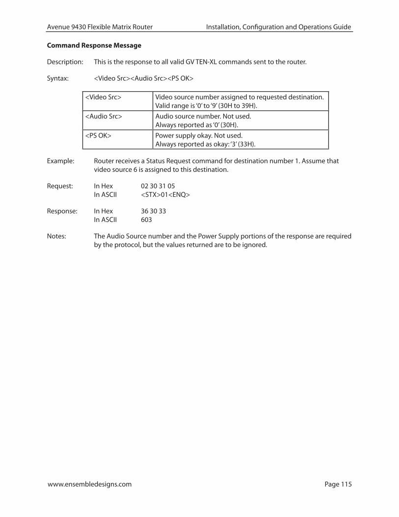
www.ensembledesigns.com Page 115
Avenue 9430 Flexible Matrix Router Installation, Configuration and Operations Guide
Command Response Message
Description: This is the response to all valid GV TEN-XL commands sent to the router.
Syntax: <Video Src><Audio Src><PS OK>
<Video Src> Video source number assigned to requested destination. Valid range is ‘0’ to ‘9’ (30H to 39H).
<Audio Src> Audio source number. Not used. Always reported as ‘0’ (30H).
<PS OK> Power supply okay. Not used. Always reported as okay: ‘3’ (33H).
Example: Router receives a Status Request command for destination number 1. Assume that video source 6 is assigned to this destination.
Request: In Hex 02 30 31 05 In ASCII <STX>01<ENQ>
Response: In Hex 36 30 33 In ASCII 603
Notes: The Audio Source number and the Power Supply portions of the response are required by the protocol, but the values returned are to be ignored.

www.ensembledesigns.com Page 116
Avenue 9430 Flexible Matrix Router Installation, Configuration and Operations Guide
7.2 GV Performer ASCII ProtocolThe Grass Valley Performer ASCII protocol is a serial protocol used by the Performer™ 10 x 1 Routing Switcher. For installations that already support this protocol, this is a good choice to minimize programming changes to the automation system.
The implementation of this protocol has been adapted as appropriate to reflect the features in the 9430 Router.
7.2.1 Protocol Requirements
• Sources and destinations are numbered starting at 1.
• The 9430 Router supports source and destination numbers beyond the limit specified in the original protocol. However, any valid source or destination in the 9430 Router can be specified in this implementation of the protocol.
• The maximum byte count for Cmd Data is 251 bytes (FBH).
• Multiple commands may be sent within a single message.
• All digits in messages are ASCII hex digits. For example, a message length specified with a high digit of ‘1’ and a low digit of ‘2’ represents the hexadecimal number 12H, or decimal 18.
• ASCII hex digits are not case specific. The 9430 Router will accept upper or lower case ASCII hex digits.
• All messages begin with a carriage return character (0DH).
• All line feeds (0AH), spaces (20H), and nulls (00H) are ignored within messages, and are not included in the message length calculation.
• The Performer Switch 1 Address bytes in messages are ignored; however, they must be legal ASCII hex digits from ‘0’ to ‘F’.
• Errors of any kind (e.g., missing parameters, unexpected characters, out of range values, etc.) result in discarding the remaining portion of the message at the point of the error.
• The P, C, R, and Q commands are not supported and will be ignored.
• No response is sent from the 9430 Router because none of the supported commands require a response.

www.ensembledesigns.com Page 117
Avenue 9430 Flexible Matrix Router Installation, Configuration and Operations Guide
7.2.2 Message Structure
This section describes the message structure supported in the GV Performer ASCII Protocol.
A message consists of a Message Header followed by Command Data (Cmd Data). The Message Header consists of 5 bytes of information (described below). The Command Data portion can vary in size depending on which commands and how many commands are included within it.
The general message structure is as follows:
Syntax: <CR><Adr High><Adr Low><Len High><Len Low><Cmd Data>
<CR> Carriage return (0DH). Part of the Message Header.
<Adr High> High byte of Performer Switch 1 Address. Part of the Message Header. This is ignored, but must be valid ASCII hex digit. (E.g. ‘0’ to ‘9’ or ‘A’ to ‘F’).
<Adr Low> Low byte of Performer Switch 1 Address. Part of the Message Header. This is ignored, but must be valid ASCII hex digit. (E.g. ‘0’ to ‘9’ or ‘A’ to ‘F’).
<Len High> High byte of byte count for Cmd Data. Part of the Message Header. Must be valid ASCII hex digit. (E.g. ‘0’ to ‘9’ or ‘A’ to ‘F’).
<Len Low> Low byte of byte count for Cmd Data. Part of the Message Header. Must be valid ASCII hex digit. (E.g. ‘0’ to ‘9’ or ‘A’ to ‘F’).
<Cmd Data> Zero or more commands consisting of valid ASCII characters.
7.2.3 Commands
This section describes the commands in the GV Performer ASCII Protocol that are supported by the 9430 Router. Commands in the original protocol that are not supported by the 9430 Router will simply be ignored.
The commands described here fit into the <Cmd Data> field of the message described in “Message Structure” above on this page.
Note that multiple commands may be sent in a single message up to a maximum of 251 bytes.
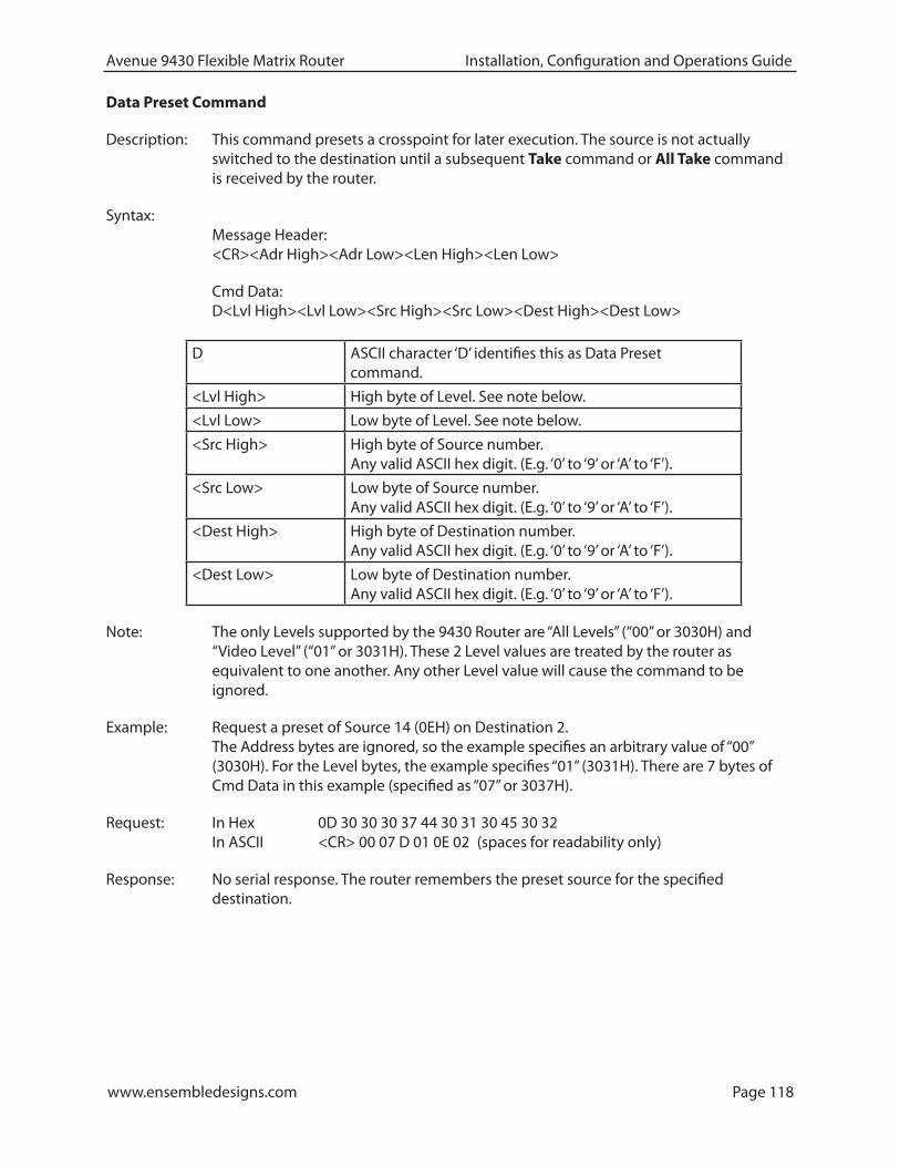
www.ensembledesigns.com Page 118
Avenue 9430 Flexible Matrix Router Installation, Configuration and Operations Guide
Data Preset Command
Description: This command presets a crosspoint for later execution. The source is not actually switched to the destination until a subsequent Take command or All Take command is received by the router.
Syntax: Message Header: <CR><Adr High><Adr Low><Len High><Len Low>
Cmd Data: D<Lvl High><Lvl Low><Src High><Src Low><Dest High><Dest Low>
D ASCII character ‘D’ identifies this as Data Preset command.
<Lvl High> High byte of Level. See note below.
<Lvl Low> Low byte of Level. See note below.
<Src High> High byte of Source number. Any valid ASCII hex digit. (E.g. ‘0’ to ‘9’ or ‘A’ to ‘F’).
<Src Low> Low byte of Source number. Any valid ASCII hex digit. (E.g. ‘0’ to ‘9’ or ‘A’ to ‘F’).
<Dest High> High byte of Destination number. Any valid ASCII hex digit. (E.g. ‘0’ to ‘9’ or ‘A’ to ‘F’).
<Dest Low> Low byte of Destination number. Any valid ASCII hex digit. (E.g. ‘0’ to ‘9’ or ‘A’ to ‘F’).
Note: The only Levels supported by the 9430 Router are “All Levels” (“00” or 3030H) and “Video Level” (“01” or 3031H). These 2 Level values are treated by the router as equivalent to one another. Any other Level value will cause the command to be ignored.
Example: Request a preset of Source 14 (0EH) on Destination 2. The Address bytes are ignored, so the example specifies an arbitrary value of “00” (3030H). For the Level bytes, the example specifies “01” (3031H). There are 7 bytes of Cmd Data in this example (specified as “07” or 3037H).
Request: In Hex 0D 30 30 30 37 44 30 31 30 45 30 32 In ASCII <CR> 00 07 D 01 0E 02 (spaces for readability only)
Response: No serial response. The router remembers the preset source for the specified destination.

www.ensembledesigns.com Page 119
Avenue 9430 Flexible Matrix Router Installation, Configuration and Operations Guide
Take Command
Description: This command requests a Take of a previously set preset source to the specified destination.
Syntax: Message Header: <CR><Adr High><Adr Low><Len High><Len Low>
Cmd Data: T<Dest High><Dest Low>
T ASCII character ‘T’ identifies this as Take cmd.
<Dest High> High byte of Destination number. Any valid ASCII hex digit. (E.g. ‘0’ to ‘9’ or ‘A’ to ‘F’).
<Dest Low> Low byte of Destination number. Any valid ASCII hex digit. (E.g. ‘0’ to ‘9’ or ‘A’ to ‘F’).
Example: Request a Take of the previous set preset source to Destination 4.
Request: In Hex 0D 30 30 30 33 54 30 34 In ASCII <CR> 00 03 T 04 (spaces for readability only)
Response: No serial response. If a preset source had previously been set for Destination 4, the router now switches that source to Destination 4.

www.ensembledesigns.com Page 120
Avenue 9430 Flexible Matrix Router Installation, Configuration and Operations Guide
All Take Command
Description: This command requests a Take of all previously set preset sources to their respective destinations.
Syntax: Message Header: <CR><Adr High><Adr Low><Len High><Len Low>
Cmd Data: A
A ASCII character ‘A’ identifies this as All Take command.
Example: Request a Take of all the previously set preset sources to their respective destinations.
Request: In Hex 0D 30 30 30 31 41 In ASCII <CR> 00 01 A (spaces for readability only)
Response: No serial response. All preset sources are switched to their respective destinations.
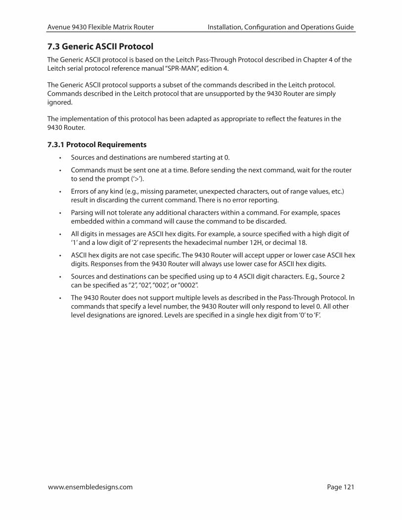
www.ensembledesigns.com Page 121
Avenue 9430 Flexible Matrix Router Installation, Configuration and Operations Guide
7.3 Generic ASCII ProtocolThe Generic ASCII protocol is based on the Leitch Pass-Through Protocol described in Chapter 4 of the Leitch serial protocol reference manual “SPR-MAN”, edition 4.
The Generic ASCII protocol supports a subset of the commands described in the Leitch protocol. Commands described in the Leitch protocol that are unsupported by the 9430 Router are simply ignored.
The implementation of this protocol has been adapted as appropriate to reflect the features in the 9430 Router.
7.3.1 Protocol Requirements
• Sources and destinations are numbered starting at 0.
• Commands must be sent one at a time. Before sending the next command, wait for the router to send the prompt (‘>’).
• Errors of any kind (e.g., missing parameter, unexpected characters, out of range values, etc.) result in discarding the current command. There is no error reporting.
• Parsing will not tolerate any additional characters within a command. For example, spaces embedded within a command will cause the command to be discarded.
• All digits in messages are ASCII hex digits. For example, a source specified with a high digit of ‘1’ and a low digit of ‘2’ represents the hexadecimal number 12H, or decimal 18.
• ASCII hex digits are not case specific. The 9430 Router will accept upper or lower case ASCII hex digits. Responses from the 9430 Router will always use lower case for ASCII hex digits.
• Sources and destinations can be specified using up to 4 ASCII digit characters. E.g., Source 2 can be specified as “2”, “02”, “002”, or “0002”.
• The 9430 Router does not support multiple levels as described in the Pass-Through Protocol. In commands that specify a level number, the 9430 Router will only respond to level 0. All other level designations are ignored. Levels are specified in a single hex digit from ‘0’ to ‘F’.

www.ensembledesigns.com Page 122
Avenue 9430 Flexible Matrix Router Installation, Configuration and Operations Guide
7.3.2 Router Responses
All commands sent to the 9430 Router must be terminated with a carriage return character (0DH). Upon receiving a carriage return, the 9430 Router will send a response to the automation system.
The possible responses are a simple Prompt Response or a Status Response followed by a Prompt Response. These are discussed below.
Prompt Response This response consists of the single ASCII character ‘>’ (3EH).
The 9430 Router will send this response anytime it receives a carriage return. This is an indication to the automation system that the router is ready for the next command.
If a command is sent to the 9430 Router that requires a more extensive response, the Prompt Response will be sent immediately following the more extensive response.

www.ensembledesigns.com Page 123
Avenue 9430 Flexible Matrix Router Installation, Configuration and Operations Guide
Status Response Certain commands sent to the 9430 Router require that a Status Response be returned by the router. This response identifies the source that is currently switched to the destination specified. The response takes this form:
Syntax: S:<Lvl><Dest>,<Src><CR><LF>
S: ASCII character ‘S’ (53H) followed by ASCII character ‘:‘ (3AH). Identifies this as a Status Response.
<Lvl> This is the level. The 9430 Router will always report this to 0.
<Dest> Destination number. No leading zeros will be used. Any valid ASCII hex digits. (E.g. ‘0’ to ‘9’ or ‘A’ to ‘F’).
, Comma character (2CH). Separates destination numbers from source numbers.
<Src> Source number. No leading zeros will be used. Any valid ASCII hex digits. (E.g. ‘0’ to ‘9’ or ‘A’ to ‘F’).
<CR> ASCII carriage return character (0DH).
<LF> ASCII line feed character (0AH).
Example: In response to a Direct Crosspoint Take command, suppose that the 9430 Router reports that Source 11 (0BH) is selected on Destination 4. The response would look as follows. (Note that the router will always report the Level as 0):
Response: In Hex 53 3A 30 34 2C 62 0D 0A In ASCII S:04,b<CR><LF>
Note: After the Status Response is sent, a Prompt Response is sent.
7.3.3 Commands
This section lists the commands supported in the Generic ASCII protocol.
Commands from the original Leitch Pass-Through Protocol that are not listed in this section are not supported by the 9430 router and will be ignored.

www.ensembledesigns.com Page 124
Avenue 9430 Flexible Matrix Router Installation, Configuration and Operations Guide
Direct Crosspoint Take Command
Description: This command requests a Take operation on the specified destination-source pair(s).
Syntax: @<Space>X:<Lvls>/<Dest>,<Src>[/<Dest>,<Src>…]<CR>
@<Space> ASCII ‘@’ (40H) followed by ASCII space character ‘ ’ (20H). Identifies the start of a command.
X: ASCII ‘X’ followed by ASCII ‘:’. Identifies this as a Direct Crosspoint Take command.
<Lvls> The level(s) to be affected. Multiple levels may be specified by listing several digits in a row. The 9430 Router only supports level 0 and ignores other levels. A level is specified by a single valid ASCII hex digit. (E.g. ‘0’ to ‘9’ or ‘A’ to ‘F’).
/ ASCII forward slash character ‘/’ (2FH). Separates Levels from destination-source pairs. Forward slash is also used to separate multiple destination-source pairs when more than one pair is specified.
<Dest> Destination number. Up to 4 characters (including leading zeros) may be used to specify the destination. Any valid ASCII hex digits. (E.g. ‘0’ to ‘9’ or ‘A’ to ‘F’).
, Comma character (2CH). Separates destination numbers from source numbers in each destination-source pair.
<Src> Source number. Up to 4 characters (including leading zeros) may be used to specify the source. Any valid ASCII hex digits. (E.g. ‘0’ to ‘9’ or ‘A’ to ‘F’).
<CR> ASCII carriage return character (0DH).
Example 1: Perform a Take of Source 10 (0AH) on Destination 4. Level 0 must be specified.
Request: In Hex 40 20 58 3A 30 2F 34 2C 41 0D In ASCII @ X:0/4,A<CR>
Response: In Hex 53 3A 30 34 2C 61 0D 0A In ASCII S:04,a<CR><LF>
Example 2: Perform a Take of sources on multiple destinations: Source 9 on Destination 3, Source 7 on Destination 1, and Source 5 on Destination 2.
Request: In Hex 40 20 58 3A 30 2F 33 2C 39 2F 31 2C 37 2F 32 2C 35 0D In ASCII @ X:0/3,9/1,7/2,5<CR>
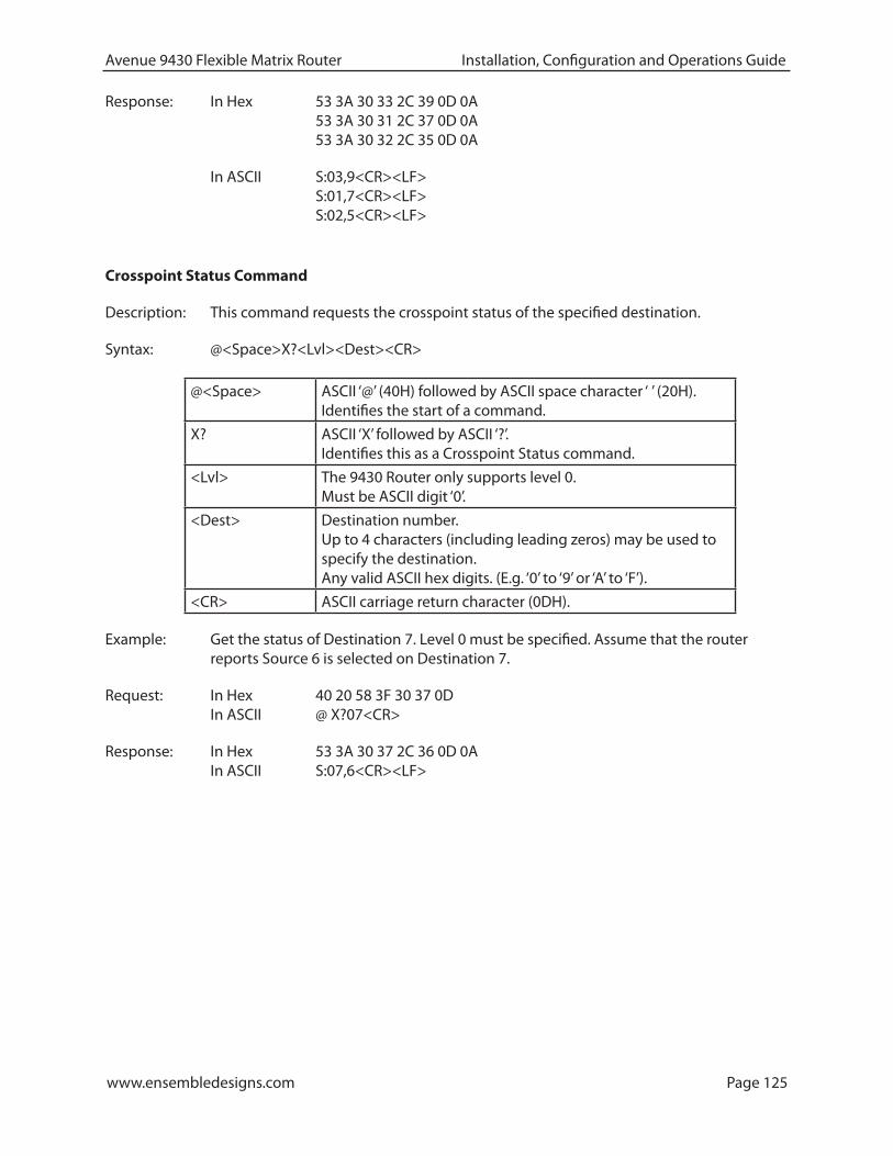
www.ensembledesigns.com Page 125
Avenue 9430 Flexible Matrix Router Installation, Configuration and Operations Guide
Response: In Hex 53 3A 30 33 2C 39 0D 0A 53 3A 30 31 2C 37 0D 0A 53 3A 30 32 2C 35 0D 0A
In ASCII S:03,9<CR><LF> S:01,7<CR><LF> S:02,5<CR><LF>
Crosspoint Status Command
Description: This command requests the crosspoint status of the specified destination.
Syntax: @<Space>X?<Lvl><Dest><CR>
@<Space> ASCII ‘@’ (40H) followed by ASCII space character ‘ ’ (20H). Identifies the start of a command.
X? ASCII ‘X’ followed by ASCII ‘?’. Identifies this as a Crosspoint Status command.
<Lvl> The 9430 Router only supports level 0. Must be ASCII digit ‘0’.
<Dest> Destination number. Up to 4 characters (including leading zeros) may be used to specify the destination. Any valid ASCII hex digits. (E.g. ‘0’ to ‘9’ or ‘A’ to ‘F’).
<CR> ASCII carriage return character (0DH).
Example: Get the status of Destination 7. Level 0 must be specified. Assume that the router reports Source 6 is selected on Destination 7.
Request: In Hex 40 20 58 3F 30 37 0D In ASCII @ X?07<CR>
Response: In Hex 53 3A 30 37 2C 36 0D 0A In ASCII S:07,6<CR><LF>
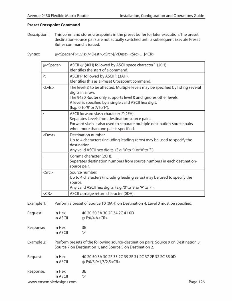
www.ensembledesigns.com Page 126
Avenue 9430 Flexible Matrix Router Installation, Configuration and Operations Guide
Preset Crosspoint Command
Description: This command stores crosspoints in the preset buffer for later execution. The preset destination-source pairs are not actually switched until a subsequent Execute Preset Buffer command is issued.
Syntax: @<Space>P:<Lvls>/<Dest>,<Src>[/<Dest>,<Src>…]<CR>
@<Space> ASCII ‘@’ (40H) followed by ASCII space character ‘ ’ (20H). Identifies the start of a command.
P: ASCII ‘P’ followed by ASCII ‘:’ (3AH). Identifies this as a Preset Crosspoint command.
<Lvls> The level(s) to be affected. Multiple levels may be specified by listing several digits in a row. The 9430 Router only supports level 0 and ignores other levels. A level is specified by a single valid ASCII hex digit. (E.g. ‘0’ to ‘9’ or ‘A’ to ‘F’).
/ ASCII forward slash character ‘/’ (2FH). Separates Levels from destination-source pairs. Forward slash is also used to separate multiple destination-source pairs when more than one pair is specified.
<Dest> Destination number. Up to 4 characters (including leading zeros) may be used to specify the destination. Any valid ASCII hex digits. (E.g. ‘0’ to ‘9’ or ‘A’ to ‘F’).
, Comma character (2CH). Separates destination numbers from source numbers in each destination-source pair.
<Src> Source number. Up to 4 characters (including leading zeros) may be used to specify the source. Any valid ASCII hex digits. (E.g. ‘0’ to ‘9’ or ‘A’ to ‘F’).
<CR> ASCII carriage return character (0DH).
Example 1: Perform a preset of Source 10 (0AH) on Destination 4. Level 0 must be specified.
Request: In Hex 40 20 50 3A 30 2F 34 2C 41 0D In ASCII @ P:0/4,A<CR>
Response: In Hex 3E In ASCII ‘>’
Example 2: Perform presets of the following source-destination pairs: Source 9 on Destination 3, Source 7 on Destination 1, and Source 5 on Destination 2.
Request: In Hex 40 20 50 3A 30 2F 33 2C 39 2F 31 2C 37 2F 32 2C 35 0D In ASCII @ P:0/3,9/1,7/2,5<CR>
Response: In Hex 3E In ASCII ‘>’
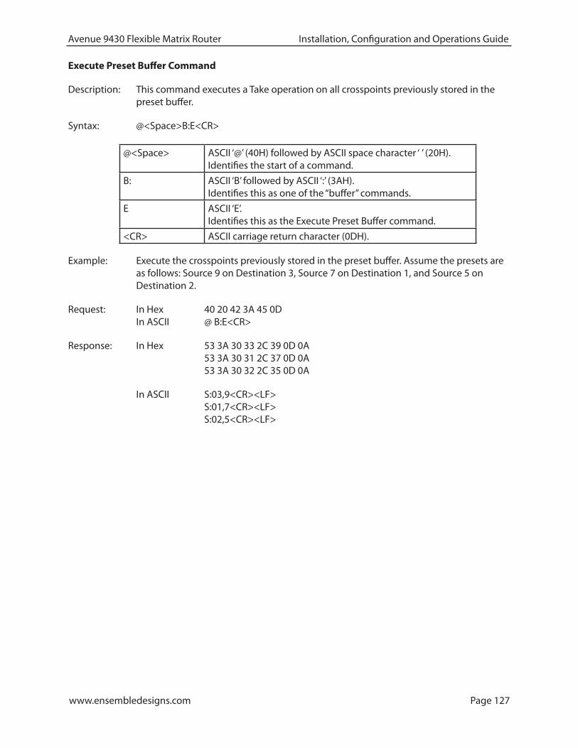
www.ensembledesigns.com Page 127
Avenue 9430 Flexible Matrix Router Installation, Configuration and Operations Guide
Execute Preset Buffer Command
Description: This command executes a Take operation on all crosspoints previously stored in the preset buffer.
Syntax: @<Space>B:E<CR>
@<Space> ASCII ‘@’ (40H) followed by ASCII space character ‘ ’ (20H). Identifies the start of a command.
B: ASCII ‘B’ followed by ASCII ‘:’ (3AH). Identifies this as one of the “buffer” commands.
E ASCII ‘E’. Identifies this as the Execute Preset Buffer command.
<CR> ASCII carriage return character (0DH).
Example: Execute the crosspoints previously stored in the preset buffer. Assume the presets are as follows: Source 9 on Destination 3, Source 7 on Destination 1, and Source 5 on Destination 2.
Request: In Hex 40 20 42 3A 45 0D In ASCII @ B:E<CR>
Response: In Hex 53 3A 30 33 2C 39 0D 0A 53 3A 30 31 2C 37 0D 0A 53 3A 30 32 2C 35 0D 0A
In ASCII S:03,9<CR><LF> S:01,7<CR><LF> S:02,5<CR><LF>

www.ensembledesigns.com Page 128
Avenue 9430 Flexible Matrix Router Installation, Configuration and Operations Guide
Clear Preset Buffer Command
Description: This command clears all crosspoints in the preset buffer.
Syntax: @<Space>B:C<CR>
@<Space> ASCII ‘@’ (40H) followed by ASCII space character ‘ ’ (20H). Identifies the start of a command.
B: ASCII ‘B’ followed by ASCII ‘:’ (3AH). Identifies this as one of the “buffer” commands.
C ASCII ‘C’ Identifies this as the Clear Preset Buffer command.
<CR> ASCII carriage return character (0DH).
Example: Clear the crosspoints previously stored in the preset buffer.
Request: In Hex 40 20 42 3A 43 0D In ASCII @ B:C<CR>
Response: In Hex 3E In ASCII ‘>’
www.ensembledesigns.com Page 129
Avenue 9430 Flexible Matrix Router Installation, Configuration and Operations Guide
Glossary
AES/EBU
The digital audio standard defined as a joint effort of the Audio Engineering Society and the European Broadcast Union. AES/EBU or AES3 describes a serial bitstream that carries two audio channels, thus an AES stream is a stereo pair. The AES/EBU standard covers a wide range of sample rates and quantizations (bit depths). In television systems, these will generally be 48 KHz and either 20 or 24 bits.
AFD
Active Format Description is a method to carry information regarding the aspect ratio of the video content. The specification of AFD was standardized by SMPTE in 2007 and is now beginning to appear in the marketplace. AFD can be included in both SD and HD SDI transport systems. There is no legacy analog implementation. (See WSS).
ASI
A commonly used transport method for MPEG video streams, ASI or Asynchronous Serial Interface, operates at the same 270 Mb/s data rate as SD SDI. This makes it easy to carry an ASI stream through existing digital television infrastructure. Known more formally as DVB-ASI, this transport mechanism can be used to carry multiple program channels.
Aspect Ratio
The ratio of the vertical and horizontal measurements of an image. 4:3 is the aspect ratio for standard definition video formats and television and 16:9 for high definition. Converting formats of unequal ratios is done by letterboxing (horizontal bars) or pillar boxing (vertical pillars) in order to keep the original format’s aspect ratio.
Bandwidth
Strictly speaking, this refers to the range of frequencies (i.e. the width of the band of frequency) used by a signal, or carried by a transmission channel. Generally, wider bandwidth will carry and reproduce a signal with greater fidelity and accuracy.
Beta
Sony Beta SP video tape machines use an analog component format that is similar to SMPTE, but differs in the amplitude of the color difference signals. It may also carry setup on the luminance channel.
Bit
A binary digit, or bit, is the smallest amount of information that can be stored or transmitted digitally by electrical, optical, magnetic, or other means. A single bit can take on one of two states: On/Off, Low/High, Asserted/ Deasserted, etc. It is represented numerically by the numerals 1 (one) and 0 (zero). A byte, containing 8 bits, can represent 256 different states. The binary number 11010111, for example, has the value of 215 in our base 10 numbering system. When a value is carried digitally, each
www.ensembledesigns.com Page 130
Avenue 9430 Flexible Matrix Router Installation, Configuration and Operations Guide
additional bit of resolution will double the number of different states that can be represented. Systems that operate with a greater number of bits of resolution, or quantization, will be able to capture a signal with more detail or fidelity. Thus, a video digitizer with 12 bits of resolution will capture 4 times as much detail as one with 10 bits.
Blanking
The Horizontal and Vertical blanking intervals of a television signal refer to the time periods between lines and between fields. No picture information is transmitted during these times, which are required in CRT displays to allow the electron beam to be repositioned for the start of the next line or field. They are also used to carry synchronizing pulses which are used in transmission and recovery of the image. Although some of these needs are disappearing, the intervals themselves are retained for compatibility purposes. They have turned out to be very useful for the transmission of additional content, such as teletext and embedded audio.
CAV
Component Analog Video. This is a convenient shorthand form, but it is subject to confusion. It is sometimes used to mean ONLY color difference component formats (SMPTE or Beta), and other times to include RGB format. In any case, a CAV signal will always require 3 connectors – either Y/R-Y/B-Y, or R/G/B.
Checkfield
A Checkfield signal is a special test signal that stresses particular aspects of serial digital transmission. The performance of the Phase Locked-Loops (PLLs) in an SDI receiver must be able to tolerate long runs of 0’s and 1’s. Under normal conditions, only very short runs of these are produced due to a scrambling algorithm that is used. The Checkfield, also referred to as the Pathological test signal, will “undo” the scrambling and cause extremely long runs to occur. This test signal is very useful for testing transmission paths.
Chroma
The color or chroma content of a signal, consisting of the hue and saturation of the image. See also Color Difference.
Component
In a component video system, the totality of the image is carried by three separate but related components. This method provides the best image fidelity with the fewest artifacts, but it requires three independent transmission paths (cables). The commonly used component formats are Luminance and Color Difference (Y/Pr/Pb), and RGB. It was far too unwieldy in the early days of color television to even consider component transmission.
Composite
Composite television dates back to the early days of color transmission. This scheme encodes the color difference information onto a color subcarrier. The instantaneous phase of the subcarrier is the color’s hue, and the amplitude is the color’s saturation or intensity. This subcarrier is then added onto the existing luminance video signal. This trick works because the subcarrier is set at a high enough frequency to leave spectrum for the luminance information. But it is not a seamless matter to pull

www.ensembledesigns.com Page 131
Avenue 9430 Flexible Matrix Router Installation, Configuration and Operations Guide
the signal apart again at the destination in order to display it or process it. The resultant artifacts of dot crawl (also referred to as chroma crawl) are only the most obvious result. Composite television is the most commonly used format throughout the world, either as PAL or NTSC. It is also referred to as Encoded video.
Color Difference
Color Difference systems take advantage of the details of human vision. We have more acuity in our black and white vision than we do in color. This means that we need only the luminance information to be carried at full bandwidth, we can scrimp on the color channels. In order to do this, RGB information is converted to carry all of the luminance (Y is the black and white of the scene) in a single channel. The other two channels are used to carry the “color difference”. Noted as B-Y and R-Y, these two signals describe how a particular pixel “differs” from being purely black and white. These channels typically have only half the bandwidth of the luminance.
Decibel (dB)
The decibel is a unit of measure used to express the ratio in the amplitude or power of two signals. A difference of 20 dB corresponds to a 10:1 ratio between two signals, 6 dB is approximately a 2:1 ratio. Decibels add while the ratios multiply, so 26 dB is a 20:1 ratio, and 14 dB is a 5:1 ratio. There are several special cases of the dB scale, where the reference is implied. Thus, dBm refers to power relative to 1 milliwatt, and dBu refers to voltage relative to .775V RMS. The original unit of measure was the Bel (10 times bigger), named after Alexander Graham Bell.
dBFS
In Digital Audio systems, the largest numerical value that can be represented is referred to as Full Scale. No values or audio levels greater than FS can be reproduced because they would be clipped. The nominal operating point (roughly corresponding to 0 VU) must be set below FS in order to have headroom for audio peaks. This operating point is described relative to FS, so a digital reference level of -20 dBFS has 20 dB of headroom before hitting the FS clipping point.
DVI
Digital Visual Interface. DVI-I (integrated) provides both digital and analog connectivity. The larger group of pins on the connector are digital while the four pins on the right are analog.
EDH
Error Detection and Handling is a method to verify proper reception of an SDI or HD-SDI signal at the destination. The originating device inserts a data packet in the vertical interval of the SDI signal and every line of the HD signal which contains a checksum of the entire video frame. This checksum is formed by adding up the numerical values of all of the samples in the frame, using a complex formula. At the destination this same formula is applied to the incoming video and the resulting value is compared to the one included in the transmission. If they match, then the content has all arrived with no errors. If they don’t, then an error has occurred.
Embedded Audio
Digital Audio can be carried along in the same bitstream as an SDI or HD-SDI signal by taking advantage of the gaps in the transmission which correspond to the horizontal and vertical intervals

www.ensembledesigns.com Page 132
Avenue 9430 Flexible Matrix Router Installation, Configuration and Operations Guide
of the television waveform. This technique can be very cost effective in transmission and routing, but can also add complexity to signal handling issues because the audio content can no longer be treated independently of the video.
Eye Pattern
To analyze a digital bitstream, the signal can be displayed visually on an oscilloscope by triggering the horizontal timebase with a clock extracted from the stream. Since the bit positions in the stream form a very regular cadence, the resulting display will look like an eye – an oval with slightly pointed left and right ends. It is easy to see from this display if the eye is “open”, with a large central area that is free of negative or positive transitions, or “closed” where those transitions are encroaching toward the center. In the first case, the open eye indicates that recovery of data from the stream can be made reliably and with few errors. But in the closed case data will be difficult to extract and bit errors will occur. Generally it is jitter in the signal that is the enemy of the eye.
Frame Sync
A Frame Synchronizer is used to synchronize the timing of a video signal to coincide with a timing reference (usually a color black signal that is distributed throughout a facility). The synchronizer accomplishes this by writing the incoming video into a frame buffer memory under the timing direction of the sync information contained in that video. Simultaneously the memory is being read back by a timing system that is genlocked to a house reference. As a result, the timing or alignment of the video frame can be adjusted so that the scan of the upper left corner of the image is happening simultaneously on all sources. This is a requirement for both analog and digital systems in order to perform video effects or switch glitch-free in a router. Frame synchronization can only be performed within a single television line standard. A synchronizer will not convert an NTSC signal to a PAL signal, it takes a standards converter to do that.
Frequency Response
A measurement of the accuracy of a system to carry or reproduce a range of signal frequencies. Similar to Bandwidth.
H.264
The latest salvo in the compression wars is H.264 which is also known as MPEG-4 Part 10. MPEG-4 promises good results at just half the bit rate required by MPEG-2.
HD
High Definition. This two letter acronym has certainly become very popular. Here we thought it was all about the pictures – and the radio industry stole it.
HDMI
The High Definition Multimedia Interface comes to us from the consumer marketplace where it is becoming the de facto standard for the digital interconnect of display devices to audio and video sources. It is an uncompressed, all-digital interface that transmits digital video and eight channels of digital audio. HDMI is a bit serial interface that carries the video content in digital component form over multiple twisted-pairs. HDMI is closely related to the DVI interface for desktop computers and their displays.

www.ensembledesigns.com Page 133
Avenue 9430 Flexible Matrix Router Installation, Configuration and Operations Guide
IEC
The International Electrotechnical Commission provides a wide range of worldwide standards. They have provided standardization of the AC power connection to products by means of an IEC line cord. The connection point uses three flat contact blades in a triangular arrangement, set in a rectangular connector. The IEC specification does not dictate line voltage or frequency. Therefore, the user must take care to verify that a device either has a universal input (capable of 90 to 230 volts, either 50 or 60 Hz), or that a line voltage switch, if present, is set correctly.
Interlace
Human vision can be fooled to see motion by presenting a series of images, each with a small change relative to the previous image. In order to eliminate the flicker, our eyes need to see more than 30 images per second. This is accomplished in television systems by dividing the lines that make up each video frame (which run at 25 or 30 frames per second) into two fields. All of the odd-numbered lines are transmitted in the first field, the even-numbered lines are in the second field. In this way, the repetition rate is 50 or 60 Hz, without using more bandwidth. This trick has worked well for years, but it introduces other temporal artifacts. Motion pictures use a slightly different technique to raise the repetition rate from the original 24 frames that make up each second of film—they just project each one twice.
IRE
Video level is measured on the IRE scale, where 0 IRE is black, and 100 IRE is full white. The actual voltages that these levels correspond to can vary between formats.
ITU-R 601
This is the principal standard for standard definition component digital video. It defines the luminance and color difference coding system that is also referred to as 4:2:2. The standard applies to both PAL and NTSC derived signals. They both will result in an image that contains 720 pixels horizontally, with 486 vertical pixels in NTSC, and 576 vertically in PAL. Both systems use a sample clock rate of 27 MHz, and are serialized at 270 Mb/s.
Jitter
Serial digital signals (either video or audio) are subject to the effects of jitter. This refers to the instantaneous error that can occur from one bit to the next in the exact position of each digital transition. Although the signal may be at the correct frequency on average, in the interim it varies. Some bits come slightly early, others come slightly late. The measurement of this jitter is given either as the amount of time uncertainty or as the fraction of a bit width. For 270 Mb/s SD video, the allowable jitter is 740 picoseconds, or 0.2 UI (Unit Interval – one bit width). For 1.485 Gb/s HD, the same 0.2UI spec corresponds to just 135 pico seconds.
Luminance
The “black & white” content of the image. Human vision had more acuity in luminance, so television systems generally devote more bandwidth to the luminance content. In component systems, the luminance is referred to as Y.

www.ensembledesigns.com Page 134
Avenue 9430 Flexible Matrix Router Installation, Configuration and Operations Guide
MPEG
The Moving Picture Experts Group is an industry group that develops standards for the compression of moving pictures for television. Their work is an on-going effort. The understanding of image processing and information theory is constantly expanding. And the raw bandwidth of both the hardware and software used for this work is ever increasing. Accordingly, the compression methods available today are far superior to the algorithms that originally made the real-time compression and decompression of television possible. Today, there are many variations of these techniques, and the term MPEG has to some extent become a broad generic label.
Metadata
This word comes from the Greek, meta means ‘beyond’ or ‘after’. When used as a prefix to ‘data’, it can be thought of as ‘data about the data’. In other words, the metadata in a data stream tells you about that data – but it is not the data itself. In the television industry, this word is sometimes used correctly when, for example, we label as metadata the timecode which accompanies a video signal. That timecode tells you something about the video, i.e. when it was shot, but the timecode in and of itself is of no interest. But in our industry’s usual slovenly way in matters linguistic, the term metadata has also come to be used to describe data that is associated with the primary video in a datastream. So embedded audio will (incorrectly) be called metadata when it tells us nothing at all about the pictures. Oh well.
Multi-mode
Multi-mode fibers have a larger diameter core than single mode fibers (either 50 or 62.5 microns compared to 9 microns), and a correspondingly larger aperture. It is much easier to couple light energy into a multi-mode fiber, but internal reflections will cause multiple “modes” of the signal to propagate down the fiber. This will degrade the ability of the fiber to be used over long distances. See also Single Mode.
NTSC
The color television encoding system used in North America was originally defined by the National Television Standards Committee. This American standard has also been adopted by Canada, Mexico, Japan, Korea, and Taiwan. (This standard is referred to disparagingly as Never Twice Same Color.)
Optical
An optical interface between two devices carries data by modulating a light source. This light source is typically a laser or laser diode (similar to an LED) which is turned on and off at the bitrate of the datastream. The light is carried from one device to another through a glass fiber. The fiber’s core acts as a waveguide or lightpipe to carry the light energy from one end to another. Optical transmission has two very significant advantages over metallic copper cables. Firstly, it does not require that the two endpoint devices have any electrical connection to each other. This can be very advantageous in large facilities where problems with ground loops appear. And secondly, and most importantly, an optical interface can carry a signal for many kilometers or miles without any degradation or loss in the recovered signal. Copper is barely useful at distances of just 1000 feet.

www.ensembledesigns.com Page 135
Avenue 9430 Flexible Matrix Router Installation, Configuration and Operations Guide
Oversampling
A technique to perform digital sampling at a multiple of the required sample rate. This has the advantage of raising the Nyquist Rate (the maximum frequency which can be reproduced by a given sample rate) much higher than the desired passband. This allows more easily realized anti-aliasing filters.
PAL
During the early days of color television in North America, European broadcasters developed a competing system called Phase Alternation by Line. This slightly more complex system is better able to withstand the differential gain and phase errors that appear in amplifiers and transmission systems. Engineers at the BBC claim that it stands for Perfection At Last.
Pathological Test Pattern – see Checkfield
Progressive
An image scanning technique which progresses through all of the lines in a frame in a single pass. Computer monitors all use progressive displays. This contrasts to the interlace technique common to television systems.
Return Loss
An idealized input or output circuit will exactly match its desired impedance (generally 75 ohms) as a purely resistive element, with no reactive (capacitive or inductive) elements. In the real world, we can only approach the ideal. So, our real inputs and outputs will have some capacitance and inductance. This will create impedance matching errors, especially at higher frequencies. The Return Loss of an input or output measures how much energy is returned (reflected back due to the impedance mismatch). For digital circuits, a return loss of 15 dB is typical. This means that the energy returned is 15 dB less than the original signal. In analog circuits, a 40 dB figure is expected.
RGB
RGB systems carry the totality of the picture information as independent Red, Green, and Blue signals. Television is an additive color system, where all three components add to produce white. Because the luminance (or detail) information is carried partially in each of the RGB channels, all three must be carried at full bandwidth in order to faithfully reproduce an image.
ScH Phase
Used in composite systems, ScH Phase measures the relative phase between the leading edge of sync on line 1 of field 1 and a continuous subcarrier sinewave. Due to the arithmetic details of both PAL and NTSC, this relationship is not the same at the beginning of each frame. In PAL, the pattern repeats ever 4 frames (8 fields) which is also known as the Bruch Blanking sequence. In NTSC, the repeat is every 2 frames (4 fields). This creates enormous headaches in editing systems and the system timing of analog composite facilities.

www.ensembledesigns.com Page 136
Avenue 9430 Flexible Matrix Router Installation, Configuration and Operations Guide
Setup
In the NTSC Analog Composite standard, the term Setup refers to the addition of an artificial offset or pedestal to the luminance content. This places the Black Level of the analog signal 54 mV (7.5 IRE) positive with respect to ground. The use of Setup is a legacy from the early development of television receivers in the vacuum tube era. This positive offset helped to prevent the horizontal retrace of the electron beam from being visible on the CRT, even if Brightness and Contrast were mis-adjusted. While the use of Setup did help to prevent retrace artifacts, it did so at the expense of dynamic range (contrast) in the signal because the White Level of the signal was not changed.
Setup is optional in NTSC systems, but is never used in PAL systems (see ‘Perfection’ characteristic of PAL). This legacy of Setup continues to persist in North American NTSC systems, while it has been abandoned in Japan.
In the digital component world (SD and HD SDI) there is obviously no need for, and certainly every reason to avoid, Setup. In order for the interfaces between analog and digital systems to operate as transparently as possible, Setup must be carefully accounted for in conversion products. When performing analog to digital conversion, Setup (if present) must be removed and the signal range gained up to account for the 7.5% reduction in dynamic range. And when a digital signal is converted back to analog form, Setup (if desired on the output) must be created by reducing the dynamic range by 7.5% and adding the 54 mV positive offset. Unfortunately, there is no truly foolproof algorithm to detect the presence of Setup automatically, so it’s definitely a case of installer beware.
SDI
Serial Digital Interface. This term refers to inputs and outputs of devices that support serial digital component video. This could refer to standard definition at 270 Mb/s, HD SDI or High Definition Serial Digital video at 1.485 Gb/s, or to the newer 3G standard of High Definition video at 2.97 Gb/s.
SMPTE
The Society of Motion Picture and Television Engineers is a professional organization which has done tremendous work in setting standards for both the film and television industries. The term “SMPTE’” is also shorthand for one particular component video format - luminance and color difference.
Single Mode
A Single mode (or mono mode) optical fiber carries an optical signal on a very small diameter (9 micron) core surrounded with cladding. The small diameter means that no internally reflected lightwaves will be propagated. Thus only the original “mode” of the signal passes down the fiber. A single mode fiber used in an optical SDI system can carry a signal for up to 20 kilometers. Single mode fibers require particular care in their installation due to the extremely small optical aperture that they present at splice and connection points. See also Multi-mode.
TBC
A Time Base Corrector is a system to reduce the Time Base Error in a signal to acceptable levels. It accomplishes this by using a FIFO (First In, First Out) memory. The incoming video is written into the memory using its own jittery timing. This operation is closely associated with the actual digitization of the analog signal because the varying position of the sync timing must be mimicked by the sampling function of the analog to digital converter. A second timing system, genlocked to a stable reference,

www.ensembledesigns.com Page 137
Avenue 9430 Flexible Matrix Router Installation, Configuration and Operations Guide
is used to read the video back out of the memory. The memory acts as a dynamically adjusting delay to smooth out the imperfections in the original signal’s timing. Very often a TBC will also function as a Frame Synchronizer. See also Frame Sync.
Time Base Error
Time base error is present when there is excessive jitter or uncertainty in the line to line output timing of a video signal. This is commonly associated with playback from video tape recorders, and is particularly severe with consumer type heterodyne systems like VHS. Time base error will render a signal unusable for broadcast or editing purposes.
Timecode
Timecode, a method to uniquely identify and label every frame in a video stream, has become one of the most recognized standards ever developed by SMPTE. It uses a 24 hour clock, consisting of hours, minutes, seconds, and television frames. Originally recorded on a spare audio track, this 2400 baud signal was a significant contributor to the development of video tape editing. We now refer to this as LTC or Longitudinal Time Code because it was carried along the edge of the tape. This allowed it to be recovered in rewind and fast forward when the picture itself could not. Timecode continues to be useful today and is carried in the vertical interval as VITC, and as a digital packet as DVITC. Timecode is the true metadata.
Tri-Level Sync
For many, many years, television systems used composite black as a genlock reference source. This was a natural evolution from analog systems to digital implementations. With the advent of High Definition television, with even higher data rates and tighter jitter requirements, problems with this legacy genlock signal surfaced. Further, a reference signal with a 50 or 60 Hz frame rate was useless with 24 Hz HD systems running at film rates. Today we can think of composite black as a bi-level sync signal – it has two levels, one at sync tip and one at blanking. For HD systems, Tri-Level Sync, which has the same blanking level (at ground) of bi-level sync, but the sync pulse now has both a negative and a positive element. This keeps the signal symmetrically balanced so that its DC content is zero. And it also means that the timing pickoff point is now at the point where the signal crosses blanking and is no longer subject to variation with amplitude. This makes Tri-Level Sync a much more robust signal and one which can be delivered with less jitter.
USB
The Universal Serial Bus, developed in the computer industry to replace the previously ubiquitous RS-232 serial interface, now appears in many different forms and with many different uses. It actually forms a small local area network, allowing multiple devices to coexist on a single bus where they can be individually addressed and accessed.
VGA
Video Graphics Array. Traditional 15-pin, analog interface between a PC and monitor.

www.ensembledesigns.com Page 138
Avenue 9430 Flexible Matrix Router Installation, Configuration and Operations Guide
Word Clock
Use of Word Clock to genlock digital audio devices developed in the audio recording industry. Early digital audio products were interconnected with a massive parallel connector carrying a twisted pair for every bit in the digital audio word. A clock signal, which is a square wave at the audio sampling frequency, is carried on a 75 ohm coaxial cable. Early systems would daisychain this 44.1 or 48 kilohertz clock from one device to another with coax cable and Tee connectors. On the rising edge of this Work Clock these twisted pairs would carry the left channel, while on the falling edge, they would carry the right channel. In most television systems using digital audio, the audio sample clock frequency (and hence the ‘genlock’ between the audio and video worlds) is derived from the video genlock signal. But products that are purely audio, with no video reference capability, may still require Word Clock.
WSS
Wide Screen Signaling is used in the PAL/625 video standards, both in analog and digital form, to convey information about the aspect ratio and format of the transmitted signal. Carried in the vertical interval, much like closed captioning, it can be used to signal a television receiver to adjust its vertical or horizontal sizing to reflect incoming material. Although an NTSC specification for WSS exists, it never achieved any traction in the marketplace.
YUV
Strictly speaking, YUV does not apply to component video. The letters refer to the Luminance (Y), and the U and V encoding axes using in the PAL composite system. Since the U axis is very close to the B-Y axis, and the V axis is very close to the R-Y axis, YUV is often used as a sort of shorthand for the more long-winded “Y/R-Y/B-Y”.
Y/Cr/Cb
In digital component video, the luminance component is Y, and the two color difference signals are Cr (R-Y) and Cb (B-Y).
Y/Pr/Pb
In analog component video, the image is carried in three components. The luminance is Y, the R-Y color difference signal is Pr, and the B-Y color difference signal is Pb.