model 5712 infra-red transit heat sensor - fire detection & … · 2016-06-22 · model 5712...
TRANSCRIPT
1 D1286-1
SERIES 5000
Contact Details: Patol Limited Archway House Bath Road Padworth, Reading Berkshire RG7 5HR Tel: +44 (0)1189 701 701 Fax: +44 (0)1189 701 700 Email: [email protected] Web: www.Patol.co.uk
Issue Change Date Remarks
1 Original 20/02/15
Model 5712 Infra-red Transit Heat Sensor
Document Ref: D1286
MANUAL INSTALLATION - COMISSIONING
OPERATION - MAINTENANCE
2 D1286-1
SERIES 5000
INDEX
1. INTRODUCTION 1.1 General 1.2 Principles
2. EQUIPMENT DETAIL 2.1 General Description 2.2 Type 5712 Sensor Head 2.3 Type 5020 Controller 2.4 General Specification (Sensor and Controller) 2.5 Operational Programmability – DIL Switch 2.6 Connections 3. INSTALLATION 3.1 Sensor Head 3.2 Controller Cable 3.3 Purge Air Supply 4. COMMISSIONING 4.1 Cable Checks 4.2 Procedure 4.3 Power Up Procedure 4.4 Hot Body Simulation Tests 5. OPERATION 5.1 Normal 5.2 Alarm Condition 5.3 Trip condition 5.4 Reset 5.5 Fault Warning 5.6 Lamp Test 5.7 Head Test 6. MAINTENANCE 6.1 General 6.2 Fault Monitoring Functions 6.3 Infra-red Detection
3 D1286-1
SERIES 5000
1 INTRODUCTION 1.1 General
The Patol 5712 Series of equipment is specifically designed for the protection of establishments and systems where a movement of materials with a potential fire hazard is a routine occurrence. The 5712 system employs enhanced Infra-red monitoring technology that enables the detection of fire initiating materials, whilst they are being transported, at the ember and flame condition. The system has many applications within industries such as Power Generation, Coal Mining, Process Plant, Road Transportation and Rail Networks and has been specifically designed to both meet the rigors of these environments and to provide the reliability required. The equipment monitors for fire and fire potential of materials in transit. The system can detect anomalies where combustion has not yet been reached, but where there is sufficient energy for a fire initiation upon destination arrival. A typical example is in the coal feed systems on power stations where coal on the ‘out field stack’ may very well smolder with little adverse effect for long periods of time. However, if imported to the power station it may have devastating effects on conveyor systems, holding hoppers, blending plants etc. Detection of hazards at temperatures greater than 220°C including both embers and buried hot
spots. Air purged system for Dusty environments with air pressure monitoring. Eight high integrity detectors for maximum reliability. Multi-facet lensing provides wide uniform coverage superior to some ember/spark detectors. Coincidence - Double Knock - option for unit detectors as standard. Timed auto reset / coincidence analyser circuit. Tuned response - solar blind. Special configurations and application specific calibration options. Specifically designed for high EMC compliance.
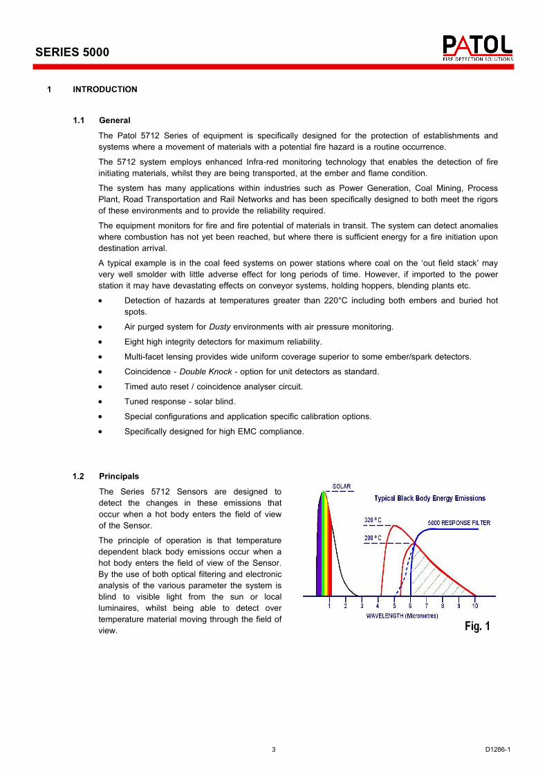
1.2 Principals The Series 5712 Sensors are designed to detect the changes in these emissions that occur when a hot body enters the field of view of the Sensor. The principle of operation is that temperature dependent black body emissions occur when a hot body enters the field of view of the Sensor. By the use of both optical filtering and electronic analysis of the various parameter the system is blind to visible light from the sun or local luminaires, whilst being able to detect over temperature material moving through the field of view.
4 D1286-1
SERIES 5000
2 EQUIPMENT DETAIL 2.1 General Description
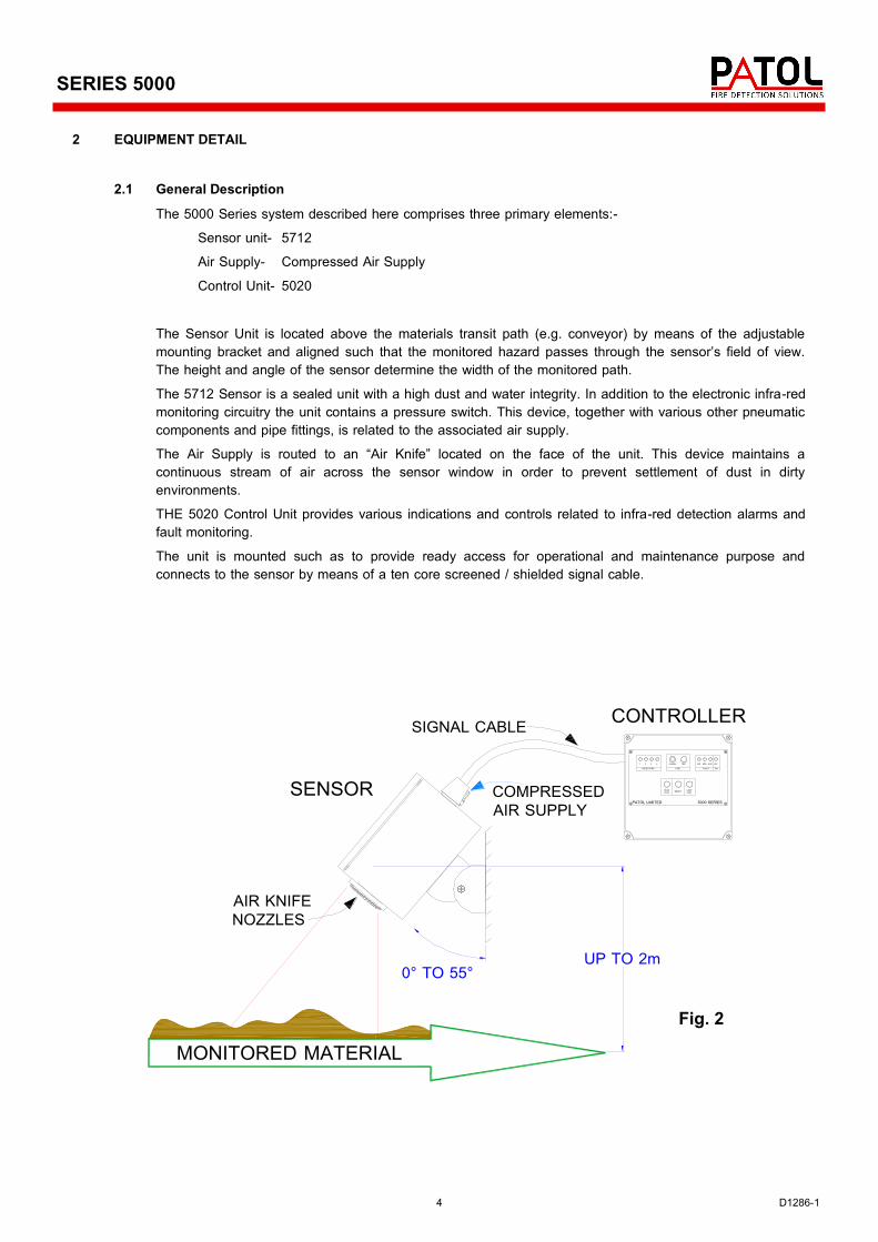
The 5000 Series system described here comprises three primary elements:- Sensor unit- 5712 Air Supply- Compressed Air Supply Control Unit- 5020 The Sensor Unit is located above the materials transit path (e.g. conveyor) by means of the adjustable mounting bracket and aligned such that the monitored hazard passes through the sensor’s field of view. The height and angle of the sensor determine the width of the monitored path. The 5712 Sensor is a sealed unit with a high dust and water integrity. In addition to the electronic infra-red monitoring circuitry the unit contains a pressure switch. This device, together with various other pneumatic components and pipe fittings, is related to the associated air supply. The Air Supply is routed to an “Air Knife” located on the face of the unit. This device maintains a continuous stream of air across the sensor window in order to prevent settlement of dust in dirty environments. THE 5020 Control Unit provides various indications and controls related to infra-red detection alarms and fault monitoring. The unit is mounted such as to provide ready access for operational and maintenance purpose and connects to the sensor by means of a ten core screened / shielded signal cable.
SENSOR
MONITORED MATERIAL
0° TO 55°UP TO 2m
AIR KNIFENOZZLES
COMPRESSEDAIR SUPPLY
ALARM TRIP
LAMPTESTRESETHEAD
TEST
FIRE FAULT
AIR SEN AUX 24V
DETECTORS
4321
ON
PATOL LIMITED 5000 SERIES
CONTROLLERSIGNAL CABLE
Fig. 2
5 D1286-1
SERIES 5000
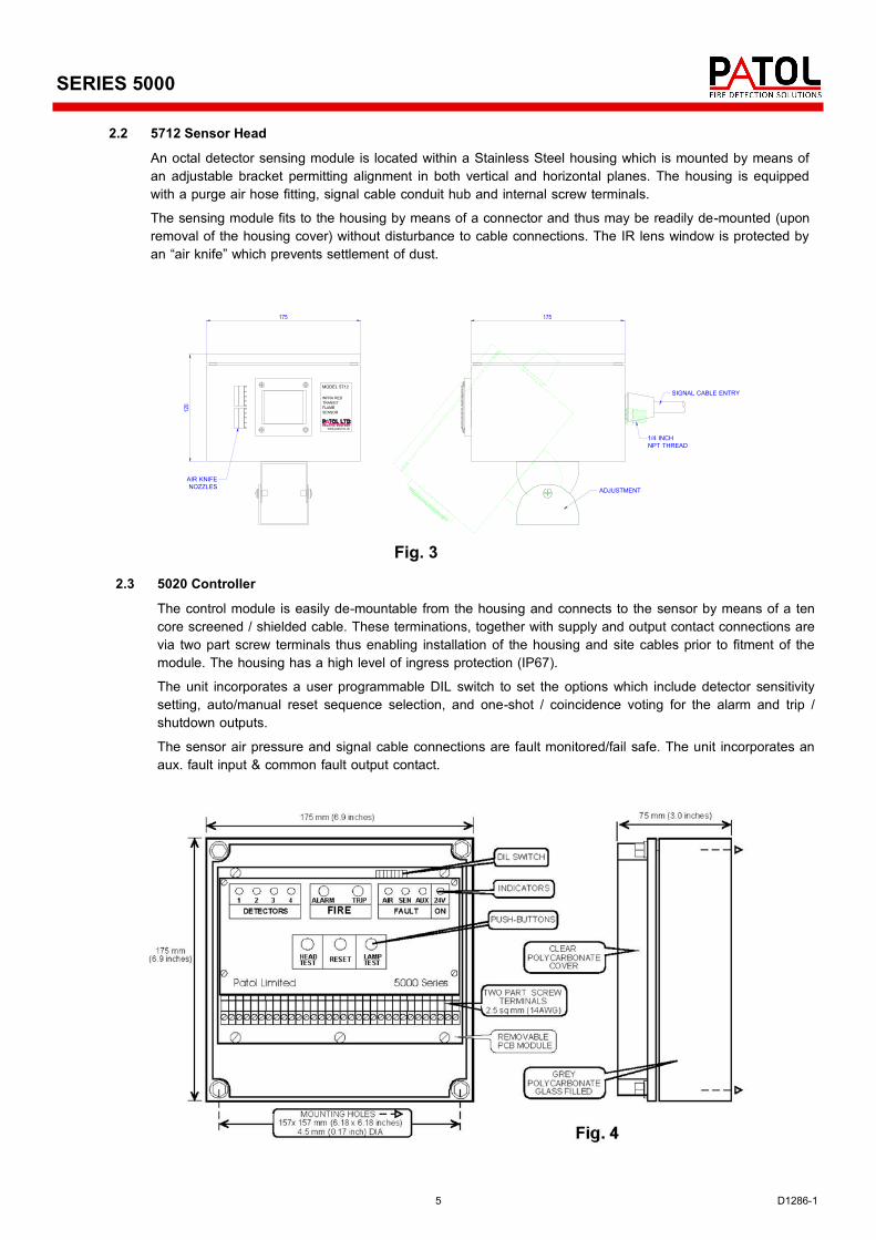
2.2 5712 Sensor Head An octal detector sensing module is located within a Stainless Steel housing which is mounted by means of an adjustable bracket permitting alignment in both vertical and horizontal planes. The housing is equipped with a purge air hose fitting, signal cable conduit hub and internal screw terminals. The sensing module fits to the housing by means of a connector and thus may be readily de-mounted (upon removal of the housing cover) without disturbance to cable connections. The IR lens window is protected by an “air knife” which prevents settlement of dust.
Fig. 3 2.3 5020 Controller
The control module is easily de-mountable from the housing and connects to the sensor by means of a ten core screened / shielded cable. These terminations, together with supply and output contact connections are via two part screw terminals thus enabling installation of the housing and site cables prior to fitment of the module. The housing has a high level of ingress protection (IP67). The unit incorporates a user programmable DIL switch to set the options which include detector sensitivity setting, auto/manual reset sequence selection, and one-shot / coincidence voting for the alarm and trip /shutdown outputs. The sensor air pressure and signal cable connections are fault monitored/fail safe. The unit incorporates an aux. fault input & common fault output contact.
175
120
AIR KNIFENOZZLES
175
ADJUSTMENT
REA DIN G ENG LANDwww.patol.co.uk
MODEL 5712
INFRA REDTRANSITFLAMESENSOR
1/4 INCHNPT THREAD
SIGNAL CABLE ENTRY
6 D1286-1
SERIES 5000
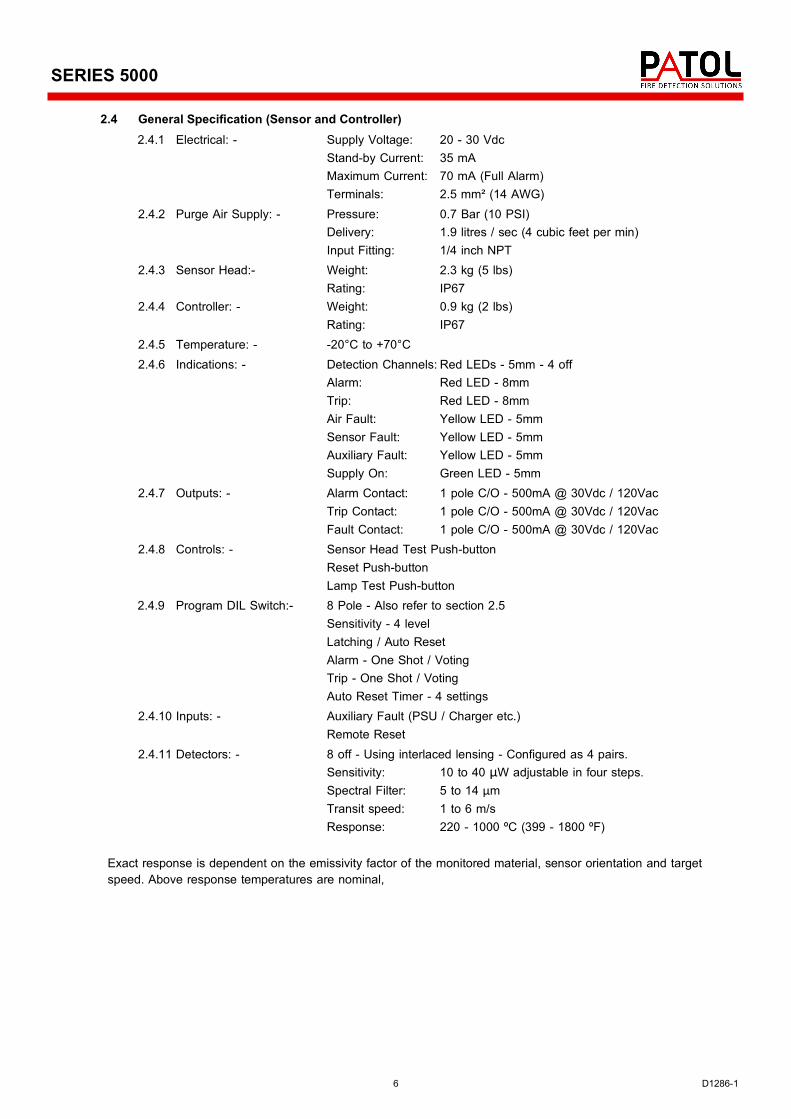
2.4 General Specification (Sensor and Controller) 2.4.1 Electrical: - Supply Voltage: 20 - 30 Vdc Stand-by Current: 35 mA
Maximum Current: 70 mA (Full Alarm) Terminals: 2.5 mm² (14 AWG)
2.4.2 Purge Air Supply: - Pressure: 0.7 Bar (10 PSI) Delivery: 1.9 litres / sec (4 cubic feet per min) Input Fitting: 1/4 inch NPT
2.4.3 Sensor Head:- Weight: 2.3 kg (5 lbs) Rating: IP67
2.4.4 Controller: - Weight: 0.9 kg (2 lbs) Rating: IP67
2.4.5 Temperature: - -20°C to +70°C 2.4.6 Indications: - Detection Channels: Red LEDs - 5mm - 4 off
Alarm: Red LED - 8mm Trip: Red LED - 8mm Air Fault: Yellow LED - 5mm Sensor Fault: Yellow LED - 5mm Auxiliary Fault: Yellow LED - 5mm Supply On: Green LED - 5mm
2.4.7 Outputs: - Alarm Contact: 1 pole C/O - 500mA @ 30Vdc / 120Vac Trip Contact: 1 pole C/O - 500mA @ 30Vdc / 120Vac Fault Contact: 1 pole C/O - 500mA @ 30Vdc / 120Vac
2.4.8 Controls: - Sensor Head Test Push-button Reset Push-button Lamp Test Push-button
2.4.9 Program DIL Switch:- 8 Pole - Also refer to section 2.5 Sensitivity - 4 level Latching / Auto Reset Alarm - One Shot / Voting Trip - One Shot / Voting Auto Reset Timer - 4 settings
2.4.10 Inputs: - Auxiliary Fault (PSU / Charger etc.) Remote Reset
2.4.11 Detectors: - 8 off - Using interlaced lensing - Configured as 4 pairs. Sensitivity: 10 to 40 μW adjustable in four steps. Spectral Filter: 5 to 14 μm Transit speed: 1 to 6 m/s Response: 220 - 1000 ºC (399 - 1800 ºF)
Exact response is dependent on the emissivity factor of the monitored material, sensor orientation and target speed. Above response temperatures are nominal,
7 D1286-1
SERIES 5000
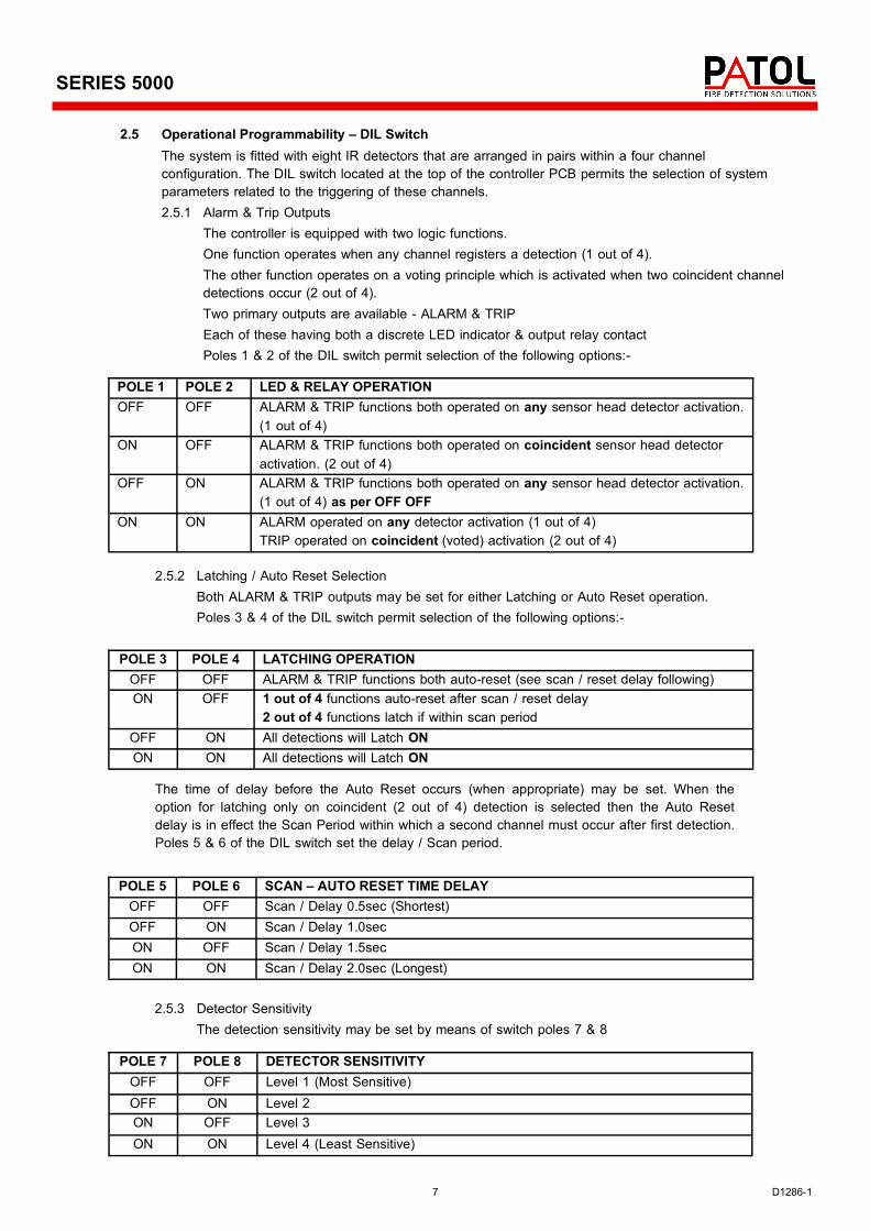
2.5 Operational Programmability – DIL Switch The system is fitted with eight IR detectors that are arranged in pairs within a four channel configuration. The DIL switch located at the top of the controller PCB permits the selection of system parameters related to the triggering of these channels.
2.5.1 Alarm & Trip Outputs The controller is equipped with two logic functions. One function operates when any channel registers a detection (1 out of 4). The other function operates on a voting principle which is activated when two coincident channel detections occur (2 out of 4). Two primary outputs are available - ALARM & TRIP Each of these having both a discrete LED indicator & output relay contact Poles 1 & 2 of the DIL switch permit selection of the following options:-
2.5.2 Latching / Auto Reset Selection Both ALARM & TRIP outputs may be set for either Latching or Auto Reset operation. Poles 3 & 4 of the DIL switch permit selection of the following options:-
POLE 3 POLE 4 LATCHING OPERATION OFF OFF ALARM & TRIP functions both auto-reset (see scan / reset delay following) ON OFF 1 out of 4 functions auto-reset after scan / reset delay
2 out of 4 functions latch if within scan period OFF ON All detections will Latch ON ON ON All detections will Latch ON
The time of delay before the Auto Reset occurs (when appropriate) may be set. When the option for latching only on coincident (2 out of 4) detection is selected then the Auto Reset delay is in effect the Scan Period within which a second channel must occur after first detection. Poles 5 & 6 of the DIL switch set the delay / Scan period.
2.5.3 Detector Sensitivity The detection sensitivity may be set by means of switch poles 7 & 8
POLE 1 POLE 2 LED & RELAY OPERATION OFF OFF ALARM & TRIP functions both operated on any sensor head detector activation.
(1 out of 4) ON OFF ALARM & TRIP functions both operated on coincident sensor head detector
activation. (2 out of 4) OFF ON ALARM & TRIP functions both operated on any sensor head detector activation.
(1 out of 4) as per OFF OFF ON ON ALARM operated on any detector activation (1 out of 4)
TRIP operated on coincident (voted) activation (2 out of 4)
POLE 5 POLE 6 SCAN – AUTO RESET TIME DELAY OFF OFF Scan / Delay 0.5sec (Shortest) OFF ON Scan / Delay 1.0sec ON OFF Scan / Delay 1.5sec ON ON Scan / Delay 2.0sec (Longest)
POLE 7 POLE 8 DETECTOR SENSITIVITY OFF OFF Level 1 (Most Sensitive) OFF ON Level 2 ON OFF Level 3 ON ON Level 4 (Least Sensitive)
8 D1286-1
SERIES 5000
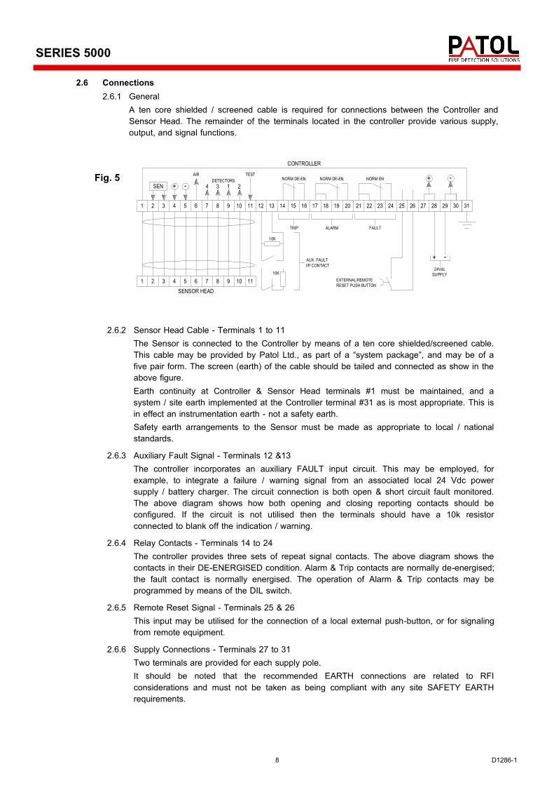
2.6.2 Sensor Head Cable - Terminals 1 to 11 The Sensor is connected to the Controller by means of a ten core shielded/screened cable. This cable may be provided by Patol Ltd., as part of a “system package”, and may be of a five pair form. The screen (earth) of the cable should be tailed and connected as show in the above figure.
Earth continuity at Controller & Sensor Head terminals #1 must be maintained, and a system / site earth implemented at the Controller terminal #31 as is most appropriate. This is in effect an instrumentation earth - not a safety earth.
Safety earth arrangements to the Sensor must be made as appropriate to local / national standards.
2.6.3 Auxiliary Fault Signal - Terminals 12 &13 The controller incorporates an auxiliary FAULT input circuit. This may be employed, for example, to integrate a failure / warning signal from an associated local 24 Vdc power supply / battery charger. The circuit connection is both open & short circuit fault monitored. The above diagram shows how both opening and closing reporting contacts should be configured. If the circuit is not utilised then the terminals should have a 10k resistor connected to blank off the indication / warning.
2.6.4 Relay Contacts - Terminals 14 to 24 The controller provides three sets of repeat signal contacts. The above diagram shows the contacts in their DE-ENERGISED condition. Alarm & Trip contacts are normally de-energised; the fault contact is normally energised. The operation of Alarm & Trip contacts may be programmed by means of the DIL switch.
2.6.5 Remote Reset Signal - Terminals 25 & 26 This input may be utilised for the connection of a local external push-button, or for signaling from remote equipment.
2.6.6 Supply Connections - Terminals 27 to 31 Two terminals are provided for each supply pole. It should be noted that the recommended EARTH connections are related to RFI considerations and must not be taken as being compliant with any site SAFETY EARTH requirements.
1 2 3 4 5 6 7 8 9 10 11 12 13 14 15 16 17 18 19 20 21 22 23 24 25 26 27 28 29 30 31
1 2 3 4 5 6 7 8 9 10 11
4 3 1 2+ -SEN
AIR TEST
DETECTORS NORM DE-EN NORM DE-EN NORM EN + -
TRIP ALARM FAULT
SENSOR HEAD
10K
10K
AUX. FAULT
I/P CONTACT
EXTERNAL/REMOTE
RESET PUSH BUTTON
24Vdc
SUPPLY
+ -
CONTROLLER
Fig. 5
2.6 Connections 2.6.1 General
A ten core shielded / screened cable is required for connections between the Controller and Sensor Head. The remainder of the terminals located in the controller provide various supply, output, and signal functions.
9 D1286-1
SERIES 5000
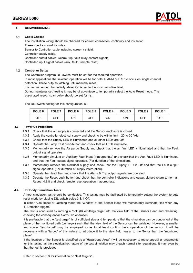
The example shown on the chart is for a sensor mounted 0.8m above the transit path at an angle of 30°. This provides a maximum monitored width of 1.3m which would be suitable for most coal conveyors. The minimum recommended angle is 30°. Should the most practical mounting height (e.g. 1m) produce a wider view field than the conveyor this is perfectly acceptable, so long as the “overlap” on each side is not so large that external hot targets, such as vehicles on an adjacent roadway, are not within the units view.
3.2 Controller Cable On sites defined as “Hazardous Areas” it will normally be a requirement that cables are installed in conduit. The Type 5712 Sensors are fitted with a conduit coupling. In order to permit adjustments to sensor alignment it is recommended that a short length of approved flexible conduit is fitted between Sensor Head and an adjacent junction box. Cable terminations at both Sensor and Controller are made at plug in screw terminal connectors with reference to the Figure 5 in Section 2.6.
3.3 Purge Air Supply
The compressed air requirement is approximately 10 P.S.I (0.7 bar) regulated and filtered, with a delivery capability of 4 cubic foot per minute (1.9 litres per second). It is normal practice to provide a regulated filter/water trap in the “local” air supply feed to the Sensor. The pressure/delivery requirement is at the Sensor Head input. The installation must take to account any pressure losses in air supply pipe work. Connection of the compressed air supply to the 5712 unit is via a 1/4 inch NPT male thread fitting mounted on the outside case. (See Fig.3)
Fig. 7
Fig. 7
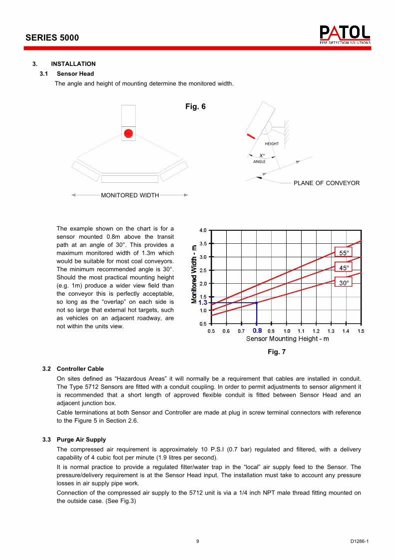
X°
PLANE OF CONVEYORMONITORED WIDTH
ANGLE
HEIGHT
3. INSTALLATION 3.1 Sensor Head
The angle and height of mounting determine the monitored width.
Fig. 6
10 D1286-1
SERIES 5000
4. COMMISSIONING 4.1 Cable Checks
The installation wiring should be checked for correct connection, continuity and insulation. These checks should include:- Sensor to Controller cable including screen / shield. Controller supply cable. Controller output cables. (alarm, trip, fault relay contact signals) Controller input signal cables (aux. fault / remote reset).
4.2 Controller Setup
The Controller program DIL switch must be set for the required operation. In most applications the selected operation will be for both ALARM & TRIP to occur on single channel detection. These outputs latching until manually reset. It is recommended that initially, detection is set to the most sensitive level. During maintenance / testing it may be of advantage to temporarily select the Auto Reset mode. The associated reset / scan delay should be set for 1s.
The DIL switch setting for this configuration is:-
POLE 8 POLE 7 POLE 6 POLE 5 POLE 4 POLE 3 POLE 2 POLE 1
OFF OFF ON OFF ON ON OFF OFF
4.3 Power Up Procedure 4.3.1 Check that the air supply is connected and the Sensor enclosure is closed. 4.3.2 Apply the controller electrical supply and check to be within limit - 20 to 30 Vdc. 4.3.3 Check that the Supply LED is illuminated and all other LEDs are Off. 4.3.4 Operate the Lamp Test push-button and check that all LEDs illuminate. 4.3.5 Momentarily remove the Air purge Supply and check that the air fault LED is illuminated and that the Fault
output signal operates 4.3.6 Momentarily simulate an Auxiliary Fault input (if appropriate) and check that the Aux Fault LED is Illuminated
and that the Fault output signal operates. (For duration of the simulation). 4.3.7 Momentarily remove the electrical supply and check that the Supply LED is Off and that the Fault output
signal operates. (For duration of supply interruption). 4.3.8 Operate the Head Test and check that the Alarm & Trip output signals are operated. 4.3.9 Operate the Reset push button and check that the controller indications and output signals return to normal.
Repeat 4.3.8 and check remote reset operation if appropriate.
4.4 Hot Body Simulation Tests A heat simulation test should be conducted. This testing may be facilitated by temporarily setting the system to auto reset mode by placing DIL switch poles 3 & 4 Off. In either Auto Reset or Latching mode the “window” of the Sensor Head will momentarily illuminate Red when any IR Detector triggers. The test is conducted by moving a “hot” (IR emitting) target into the view field of the Sensor Head and observing/checking the consequential Alarm/Trip operation. It is preferable that the “test target” is of sufficient size and temperature that the simulation can be conducted at the plane of the monitored path (conveyor) such that the view field of the Sensor can be validated. However, a smaller and cooler “test target” may be employed so as to at least confirm basic operation of the sensor. It will be necessary with a “target” of this nature to introduce it to the view field nearer to the Senor than the “monitored plane”. If the location of the Sensor is classified as a “Hazardous Area” it will be necessary to make special arrangements for this testing as the electrical/hot nature of the test simulation may breach normal site regulations. It may even be that the test is precluded. Refer to section 6.3 for information on “test targets”.
11 D1286-1
SERIES 5000
5. OPERATION 5.1 Normal
When the system is healthy only the green supply LED will be illuminated.
5.2 Alarm Condition An Alarm condition will occur on abnormal Infra-red detection by the Sensor Head. Normally this status will Latch On, however in special configurations the condition can be set to momentary operation; auto resetting after a selected delay. During the ALARM:-
One or more Red DETECTOR indicators will be illuminated. The Red ALARM indicator will be illuminated. An ALARM output is signaled by means of a relay contact.
5.3 Trip condition
A Trip condition will occur on abnormal Infra-red detection by the Sensor Head. Normally this status will be coincident with the ALARM condition and will Latch On. In special configurations the condition can be set such as to require more detector triggers than for ALARM. Similarly, the condition can be set to momentary operation; auto resetting after a pre-selected delay. During the TRIP:-
One or more Red DETECTOR indicators will be illuminated. The Red TRIP indicator will be illuminated. A TRIP output is signaled by means of a relay contact.
5.4 Reset
Latched Alarm and Trip conditions may be normalized by:- Operation of the Controller’s integral Reset push-button. Operation of the remote reset push-button / signal (if implemented)
5.5 Fault Warning
The equipment continuously monitors for various fault conditions and is equipped with indicators to identify the failure.
Yellow AIR FAULT indicator illuminated - Sensor Head “purge air” failed. Yellow SEN FAULT indicator illuminated - Sensor Head disconnected. Yellow AUX FAULT indicator illuminated - Auxiliary equipment fault input signal. Green 24 V ON indicator extinguished - Electrical supply failed.
On any of the above conditions a FAULT output is signaled by means of a relay contact. The indications and output will automatically normalize on rectification of the fault.
5.6 Lamp Test
Operation of the Controller’s integral Lamp Test push-button illuminates all indicators. Output relay signals are not initiated on this test.
5.7 Head Test
Operation of the Controller’s integral Head Test push-button signals the Sensor Head and simulates a detection condition on all circuits. The system will respond as if a true Alarm/Trip condition has occurred, including operation of Alarm & Trip relay contact outputs.
12 D1286-1
SERIES 5000
6. MAINTENANCE
6.1 General It is recommended that a System Log Book/File is raised at the Commissioning Stage and that the system configuration and initial settings recorded. These should include:- Operation configuration and Sensitivity - DIL switch set-up. Supply voltage. Purge air pressure. Subsequently all system events should be recorded in the log. These should include all maintenance activity, changes to settings, Fault warnings and Alarm/Trip occurrences. (Including cause and actions taken). An operational regime should be developed that includes both frequent inspection of the Sensor Head window for undue accumulation of dust, and use of the Lamp & Head Test controls to check basic operation. In addition, the system should be subjected to a periodic service as defined in the following.
6.2 Fault Monitoring Functions
Tests should be conducted to confirm the correct operation of the fault monitoring circuits:- 6.2.1 Purge Air Pressure - Check as per 4.3.5 6.2.2 Auxiliary Fault - Check as per 4.3.6 6.2.3 Supply Failure - Check as per 4.3.7
6.3 Infra-red Detection
A heat simulation test should be conducted by moving a “hot” (IR emitting) target into the view field of the Sensor Head and checking the consequential Alarm/Trip operation. The controller may be temporarily set for auto reset mode by means of the DIL switch. The “window” of the Sensor Head will momentarily illuminate Red on any Detector trigger. It is preferable that the “test target” is of sufficient size and temperature to enable simulation at the plane of the monitored path (conveyor) in order to validate the view field of the Sensor. Smaller and/or cooler “test targets” may be used closer to the Sensor so as to at least confirm basic operation of the Sensor. If the location of the Sensor is classified as a “Hazardous Area” it may be necessary to make special arrangements for this testing as the electrical / hot nature of the test simulation will breach normal regulations. It may even be that the test is precluded. Potential “test targets” are:- Type 5501 Infra-red Radiator - Test and Commissioning Platen - Patol product. 100W Lamp Bulb - (The Sensor responds to the glass temperature - not the visible light). Domestic Flat Iron (smoothing iron). Electrical or Catalytic soldering iron. Note: Infra-red LED Torches are NOT suitable for testing 5000 Series equipment.