model 2807 pds/pns mini-node catv receiver … · figure 2 model 2807 mini-node catv receiver ......
TRANSCRIPT
825 Park Street, Christiansburg, VA 24073 • USA (800) 732-5252 • TEL (540) 382-0462 • FAX (540) 381-0392 • [email protected] • www.forceinc.com
© 2006 by Force, Inc. Force reserves the right to make changes to the product described in this document in the interest of product improvement.
Model 2807 PDS/PNS Mini-Node CATV Receiver
Installation Guide and User Manual
IOM2807Revision 2.2, March 2006
Laser Safety WarningThe optical emissions from the return path module optical output and connected optical fiber are laser-basedand may present eye hazards. Follow all safety precautions.
Technical SupportIf you encounter any kind of problem after reading this manual, contact your local distributor or a Force, Inc.Applications Engineer. To reach technical support::
On the Web: http://www.forceinc.com
By Phone (Monday through Friday 8:00 am to 5:00 pm EST): USA (800) 732-5252TEL (540) 382-0462
By Fax: (540) 381-0392
By Email: [email protected]

Model 2807 PDS/PNS Mini-node CATV Receiver User Manual
IOM2807 Revision 2.2 2
ContentsLaser Safety Warning 1
Technical Support 1
Product Specifications 3
FCC Notice 3
Optical and Video Characteristics 3
Electrical Characteristics 4
Environmental Characteristics 4
Physical Characteristics 4
Specification Notes 4
CNR vs. Receiver Optical Input at 110 Channels 4
Installation and Operation 6
General Installation Instructions 6
Unit Physical Description 7
Model 2807 Mini-node CATV Receiver 7
Module Placement 7
Items Provided 8
Items Required 8
Inspection 8
Connections 8
Operation of the LCD Display 9
Control Button Operation 10
RF Equalization Update Mode 10
RF Attenuation Adjust Mode 11
Optical Status LED 11
Measuring RF Input Levels at the Return Path 11
Safety Precautions 11
Power-up and Operation 11
Performance Verification 12
Troubleshooting 12
Cleaning 13
Warranty and Return Policy 14
Warranty 14
Force Obligations 14
Exclusions 14
Product Return Policy 14
Products Returned for Credit - Non Distributor 15
Products Returned for Repair or Replacement 15
Active Product Under Warranty 15
Obsolete Product Under Warranty 15
Active Out of Warranty 15
Obsolete Product Out of Warranty 16
Receiving an RMA for Returns 16
IOM2807 Revision 2.2 3
Model 2807 PDS/PNS Mini-node CATV Receiver User Manual
Product Specifications
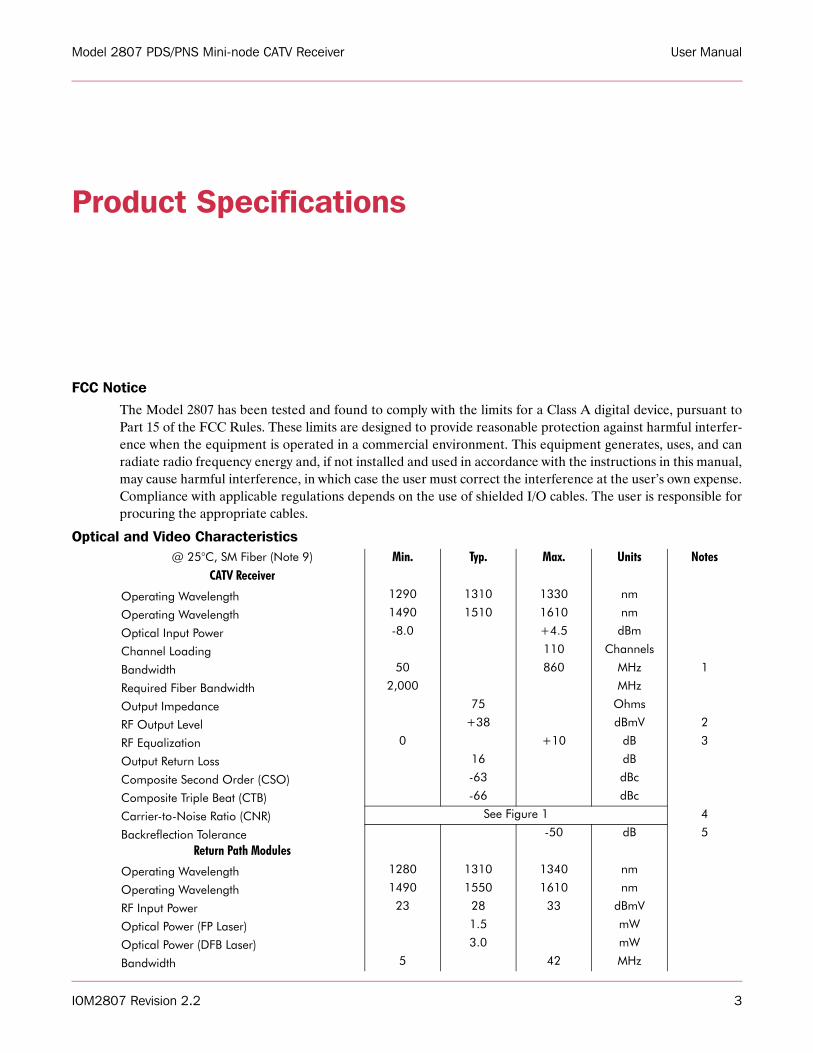
FCC NoticeThe Model 2807 has been tested and found to comply with the limits for a Class A digital device, pursuant toPart 15 of the FCC Rules. These limits are designed to provide reasonable protection against harmful interfer-ence when the equipment is operated in a commercial environment. This equipment generates, uses, and canradiate radio frequency energy and, if not installed and used in accordance with the instructions in this manual,may cause harmful interference, in which case the user must correct the interference at the user’s own expense.Compliance with applicable regulations depends on the use of shielded I/O cables. The user is responsible forprocuring the appropriate cables.
Optical and Video Characteristics@ 25°C, SM Fiber (Note 9) Min. Typ. Max. Units Notes
CATV Receiver
Operating Wavelength 1290 1310 1330 nm
Operating Wavelength 1490 1510 1610 nm
Optical Input Power -8.0 +4.5 dBm
Channel Loading 110 Channels
Bandwidth 50 860 MHz 1
Required Fiber Bandwidth 2,000 MHz
Output Impedance 75 Ohms
RF Output Level +38 dBmV 2
RF Equalization 0 +10 dB 3
Output Return Loss 16 dB
Composite Second Order (CSO) -63 dBc
Composite Triple Beat (CTB) -66 dBc
Carrier-to-Noise Ratio (CNR) See Figure 1 4
Backreflection Tolerance -50 dB 5
Return Path Modules
Operating Wavelength 1280 1310 1340 nm
Operating Wavelength 1490 1550 1610 nm
RF Input Power 23 28 33 dBmV
Optical Power (FP Laser) 1.5 mW
Optical Power (DFB Laser) 3.0 mW
Bandwidth 5 42 MHz
IOM2807 Revision 2.2 4
Model 2807 PDS/PNS Mini-node CATV Receiver User Manual
Electrical Characteristics
Environmental Characteristics
Physical Characteristics
Specification Notes1) The receiver bandwidth is 50-860 MHz when a return path transmitter is installed. 2) The 2807 Mini-node contains a user-programmable digital RF attenuator which is adjustable from 0 dB to
31 dB attenuation. The user can adjust this RF attenuator to achieve +38 dBmV per channel RF outputover the full rated optical input power. See page 9 for LCD operation details.
3) The 2807 Mini-node contains a user-programmable RF equalization function. The user has the choice offlat response (no tilt) or +10 dB tilt via the digital control panel. See page 9 for LCD operation details.
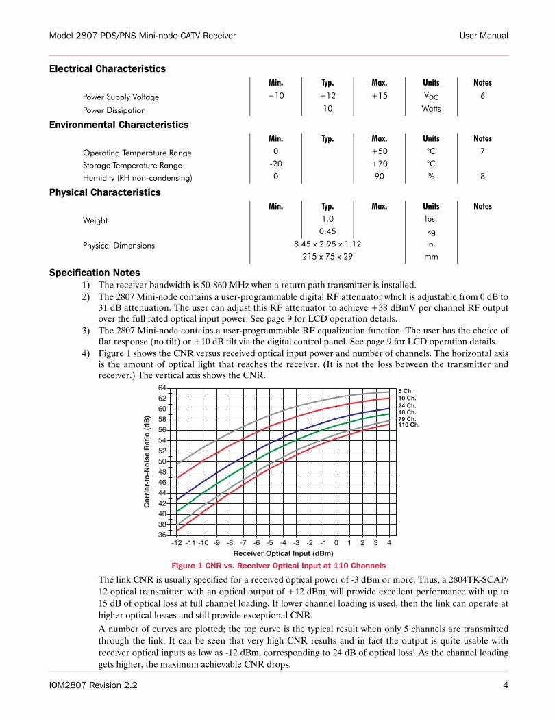
4) Figure 1 shows the CNR versus received optical input power and number of channels. The horizontal axisis the amount of optical light that reaches the receiver. (It is not the loss between the transmitter andreceiver.) The vertical axis shows the CNR.
Figure 1 CNR vs. Receiver Optical Input at 110 Channels
The link CNR is usually specified for a received optical power of -3 dBm or more. Thus, a 2804TK-SCAP/12 optical transmitter, with an optical output of +12 dBm, will provide excellent performance with up to15 dB of optical loss at full channel loading. If lower channel loading is used, then the link can operate athigher optical losses and still provide exceptional CNR. A number of curves are plotted; the top curve is the typical result when only 5 channels are transmittedthrough the link. It can be seen that very high CNR results and in fact the output is quite usable withreceiver optical inputs as low as -12 dBm, corresponding to 24 dB of optical loss! As the channel loadinggets higher, the maximum achievable CNR drops.
Min. Typ. Max. Units Notes
Power Supply Voltage +10 +12 +15 VDC 6
Power Dissipation 10 Watts
Min. Typ. Max. Units Notes
Operating Temperature Range 0 +50 °C 7
Storage Temperature Range -20 +70 °C
Humidity (RH non-condensing) 0 90 % 8
Min. Typ. Max. Units Notes
Weight 1.0 lbs.
0.45 kg
Physical Dimensions 8.45 x 2.95 x 1.12 in.
215 x 75 x 29 mm
Model 2807 PDS/PNS Mini-node CATV Receiver User Manual
IOM2807 Revision 2.2 5
5) This product must be used only with APC type optical connectors or fusion spliced connections. There issome folklore which suggests that the only critical backreflection is the one closest to the transmitter. Ourexperience does not support that view. We find that all backreflections matter, regardless of their distancefrom the transmitter.
6) The receiver is powered by the Force, Inc. Model PS200 AC adapter. See TB043 for complete specifica-tions.
7) Most parameters are relatively unaffected by varying temperature. A moving air environment is recom-mended at ambient temperatures above +35°C.
8) Humidity is RH non-condensing.9) The Model 2807 PDS/PNS Mini-node receiver is optimized for single-mode operation only.
IOM2807 Revision 2.2 6
Model 2807 PDS/PNS Mini-node CATV Receiver User Manual
Installation and Operation
General Installation InstructionsThe installation of these units is very simple. There are no special unpacking instructions, except that careshould be taken to handle the units gently. Fiber optic links are sensitive electronics devices that should behandled with care. Like most electronics, they are susceptible to ESD. Proper ESD techniques such as wearinga wrist grounding strap, should be observed at all times when handling a unit. The units should not be dropped.No assembly is required.
Do not install the equipment near sources of excessive heat, such as furnace outlets or above heat producingunits, such as large power supplies and tube-type equipment. Observe temperature and relative humidityrequirements specified on page 4.
Model 2807 PDS/PNS Mini-node CATV Receiver User Manual
IOM2807 Revision 2.2 7
Unit Physical Description
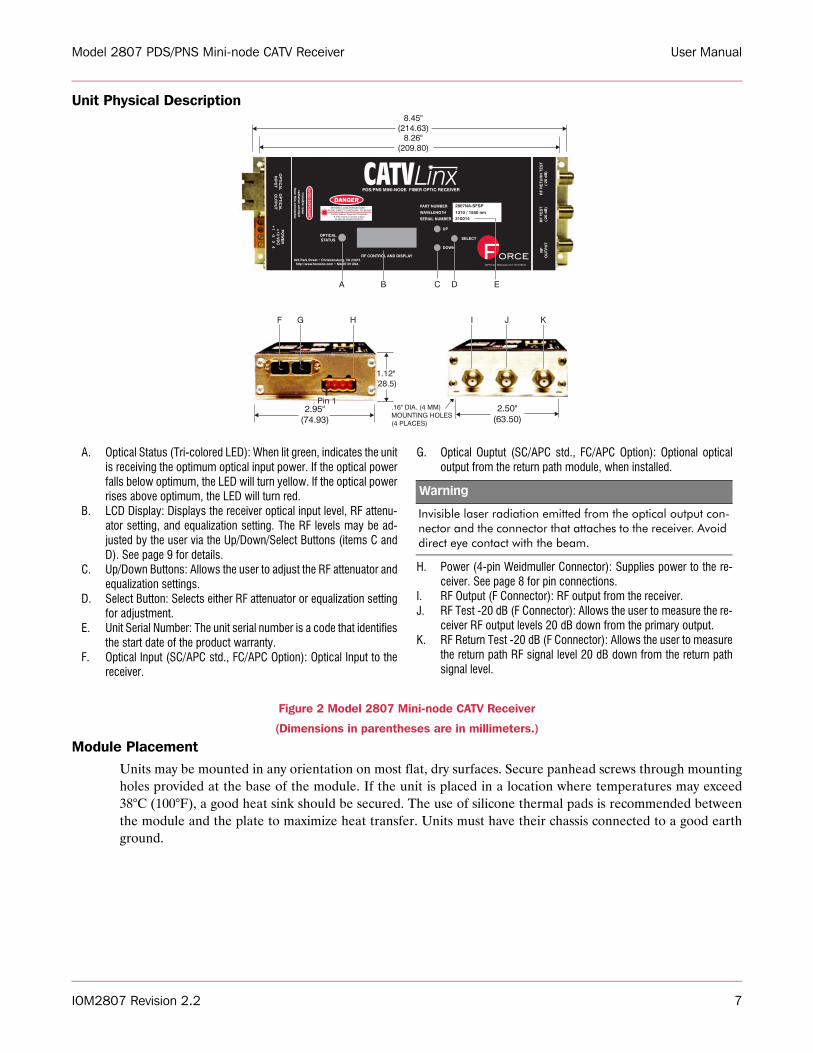
Figure 2 Model 2807 Mini-node CATV Receiver
(Dimensions in parentheses are in millimeters.)
Module PlacementUnits may be mounted in any orientation on most flat, dry surfaces. Secure panhead screws through mountingholes provided at the base of the module. If the unit is placed in a location where temperatures may exceed38°C (100°F), a good heat sink should be secured. The use of silicone thermal pads is recommended betweenthe module and the plate to maximize heat transfer. Units must have their chassis connected to a good earthground.
A. Optical Status (Tri-colored LED): When lit green, indicates the unitis receiving the optimum optical input power. If the optical powerfalls below optimum, the LED will turn yellow. If the optical powerrises above optimum, the LED will turn red.
B. LCD Display: Displays the receiver optical input level, RF attenu-ator setting, and equalization setting. The RF levels may be ad-justed by the user via the Up/Down/Select Buttons (items C andD). See page 9 for details.
C. Up/Down Buttons: Allows the user to adjust the RF attenuator andequalization settings.
D. Select Button: Selects either RF attenuator or equalization settingfor adjustment.
E. Unit Serial Number: The unit serial number is a code that identifiesthe start date of the product warranty.
F. Optical Input (SC/APC std., FC/APC Option): Optical Input to thereceiver.
G. Optical Ouptut (SC/APC std., FC/APC Option): Optional opticaloutput from the return path module, when installed.
H. Power (4-pin Weidmuller Connector): Supplies power to the re-ceiver. See page 8 for pin connections.
I. RF Output (F Connector): RF output from the receiver. J. RF Test -20 dB (F Connector): Allows the user to measure the re-
ceiver RF output levels 20 dB down from the primary output.K. RF Return Test -20 dB (F Connector): Allows the user to measure
the return path RF signal level 20 dB down from the return pathsignal level.
Warning
Invisible laser radiation emitted from the optical output con-nector and the connector that attaches to the receiver. Avoid direct eye contact with the beam.
IOM2807 Revision 2.2 8
Model 2807 PDS/PNS Mini-node CATV Receiver User Manual
Items ProvidedThe following is a list of items provided with each Model 2807:
Items Required
InspectionRemove the unit from its shipping container. Any in-shipment damage that may have occurred should be visu-ally apparent. Look for bent or damaged connectors or mounting brackets. Claims for damage incurred inshipment should be made directly to the transportation company in accordance with their instructions. Savethe shipping cartons until installation and performance verification are completed.
Connections
Qty. Mfr. P/N Description
AR Force, Inc. 2807NX-SFSPPDS/PNS Mini-node CATV Receiver, SM, 1310/1550 nm, SC/APC Standard, FC/APC Optional
1 per connector Any Any Active Device Receptacle Caps for RF and Optical Connections
Qty. Mfr. P/N Description
AR Force, Inc.2804T or
2805T110 Ch. PDS Transmitter, SM, 1310 nm, SC/APC Std, FC option.77Ch. PNS Transmitter, SM, 1310 nm, SC/APC Std., FC option.
1 per Rx Force, Inc. PS200Rx Power Supply, +15 Volts, 950 mA DC Power Supply, 4-pin Power Connector
4 per unit Any Any 6-32 Panhead Mounting Screws with Lock Washers and Nuts (for Rx)
AR Any Any EIA 19” Grounded Equipment Rack (for Tx)
1 Any Any Straight Screwdriver
AR Any Any 9/125 µm Single-mode Fiber
Connector Name Connector Type Connector Function Optical Input SC/APC or FC/APC* Optical input to the unit.
Optical OutSC/APC or FC/APC* Optical output from the return path unit.
It is imperative that backreflections be controlled to very low levels. This product must be used only with angle physical contact (APC) connectors.
Power 4-Pin Weidmuller Connector
Pin Function1 +12 Volts DC
2 Ground
3
Optical Status Flag. This is an open drain output that can sink up to 10 mA at +12 Volts. An external pull-up resistor is required. This pin will be pulled low when the optical input is within optimal range
4
Optical Input Power Meter. This is an analog voltage proportional to the amount of light reaching the detec-tor. The response is 1 Volt per mW of input light.
RF Output F Connector RF output from the unit.
RF Test F Connector RF Test (-20 dB) output for receiver.
RF Return Test F Connector RF Test (-20 dB) output for return path module (if installed).
*Note: The FC/APC interface uses the “wide-key” standard. This means that the units are optimized for use with FC/APC connectors that have a 2.14 mm wide alignment key. “Narrow-key” FC/APC connectors (2.02 mm) may be used but will produce inferior results. Standard FC/PC connectors have a 2.36 mm wide key and cannot be plugged into to the unit.
Model 2807 PDS/PNS Mini-node CATV Receiver User Manual
IOM2807 Revision 2.2 9
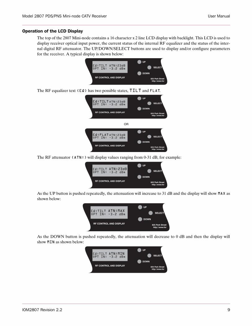
Operation of the LCD DisplayThe top of the 2807 Mini-node contains a 16 character x 2 line LCD display with backlight. This LCD is used todisplay receiver optical input power, the current status of the internal RF equalizer and the status of the inter-nal digital RF attenuator. The UP/DOWN/SELECT buttons are used to display and/or configure parametersfor the receiver. A typical display is shown below:
The RF equalizer text (EQ) has two possible states, TILT and FLAT.
The RF attenuator (ATN:) will display values ranging from 0-31 dB, for example:
As the UP button is pushed repeatedly, the attenuation will increase to 31 dB and the display will show MAX asshown below:
As the DOWN button is pushed repeatedly, the attenuation will decrease to 0 dB and then the display willshow MIN as shown below:
UP
DOWN
SELECT
RF CONTROL AND DISPLAY
EQ:TILT ATN:23dBOPT IN: -3.2 dBm
UP
UP
DOWN
DOWN
SELECT
SELECT
RF CONTROL AND DISPLAY
RF CONTROL AND DISPLAY
EQ:TILTATN:23dBOPT IN: -3.2 dBm
EQ:FLATATN:23dBOPT IN: -3.2 dBm
OR
UP
DOWN
SELECT
RF CONTROL AND DISPLAY
EQ:TILT ATN:23dBOPT IN: -3.2 dBm
UP
DOWN
SELECT
RF CONTROL AND DISPLAY
EQ:TILT ATN:MAXOPT IN: -3.2 dBm
UP
DOWN
SELECT
RF CONTROL AND DISPLAY
EQ:TILT ATN:MINOPT IN: -3.2 dBm
IOM2807 Revision 2.2 10
Model 2807 PDS/PNS Mini-node CATV Receiver User Manual
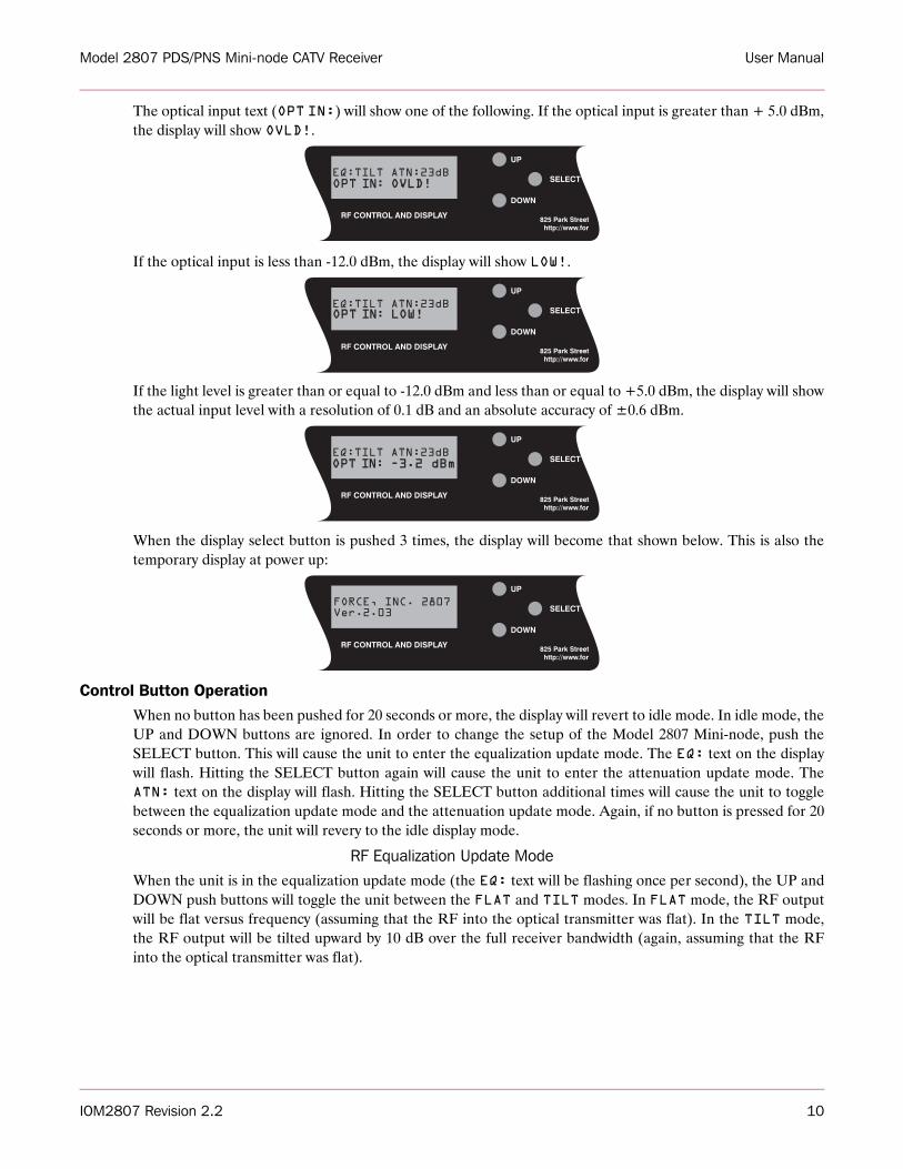
The optical input text (OPT IN:) will show one of the following. If the optical input is greater than + 5.0 dBm,the display will show OVLD!.
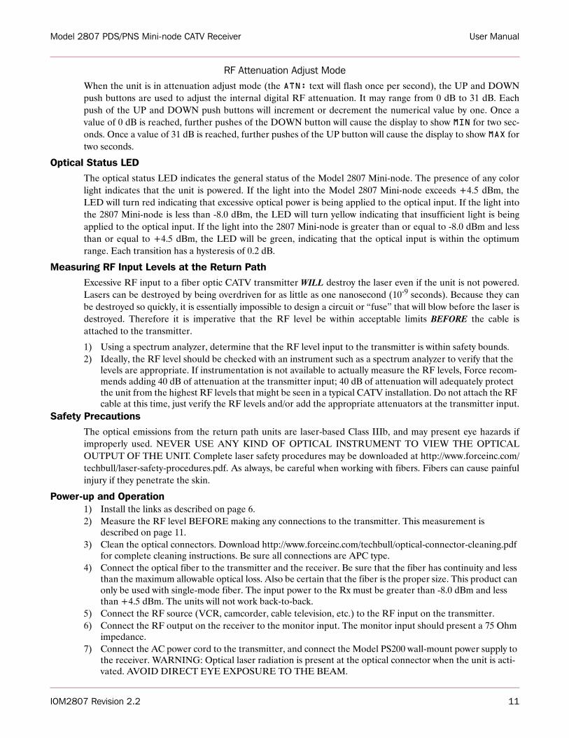
If the optical input is less than -12.0 dBm, the display will show LOW!.
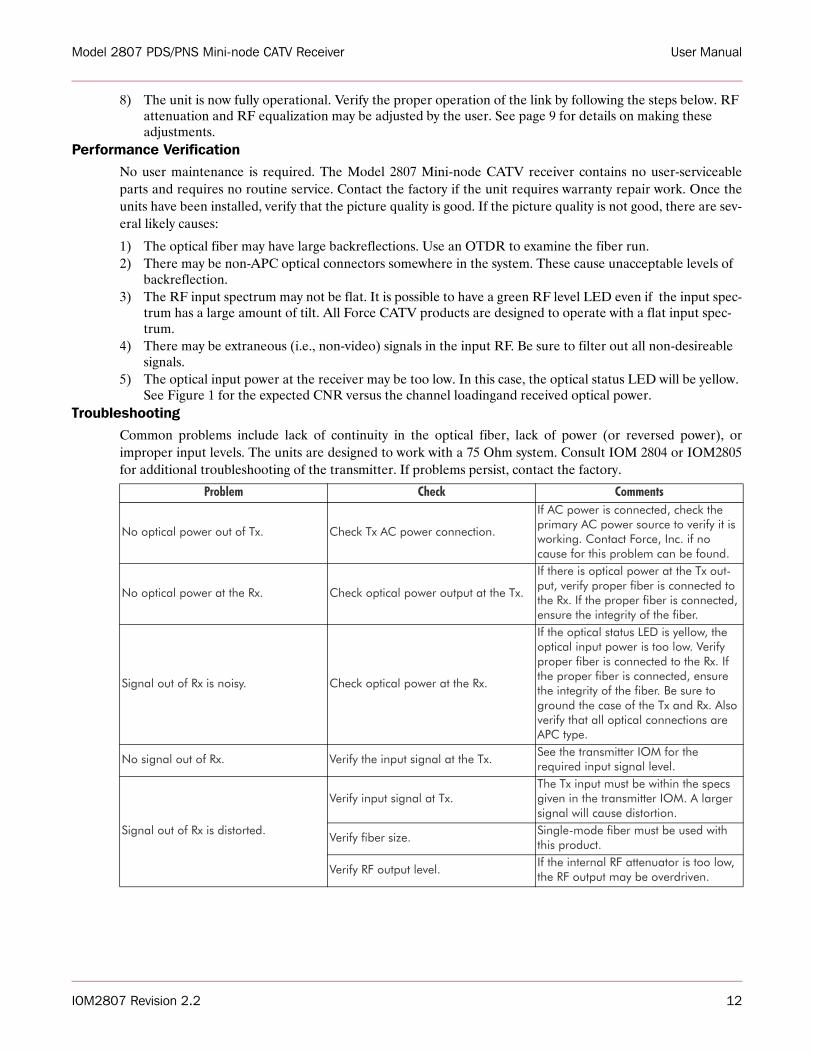
If the light level is greater than or equal to -12.0 dBm and less than or equal to +5.0 dBm, the display will showthe actual input level with a resolution of 0.1 dB and an absolute accuracy of ±0.6 dBm.
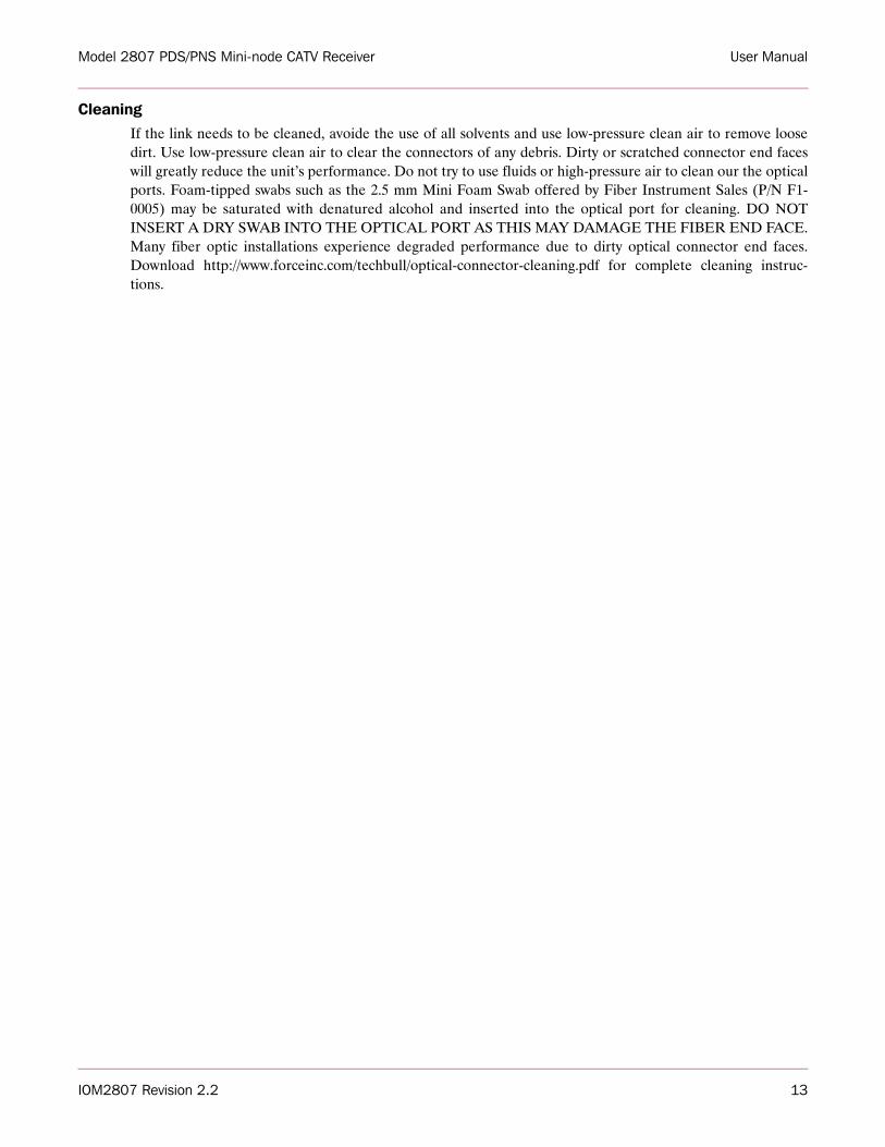
When the display select button is pushed 3 times, the display will become that shown below. This is also thetemporary display at power up:
Control Button OperationWhen no button has been pushed for 20 seconds or more, the display will revert to idle mode. In idle mode, theUP and DOWN buttons are ignored. In order to change the setup of the Model 2807 Mini-node, push theSELECT button. This will cause the unit to enter the equalization update mode. The EQ: text on the displaywill flash. Hitting the SELECT button again will cause the unit to enter the attenuation update mode. TheATN: text on the display will flash. Hitting the SELECT button additional times will cause the unit to togglebetween the equalization update mode and the attenuation update mode. Again, if no button is pressed for 20seconds or more, the unit will revery to the idle display mode.
RF Equalization Update ModeWhen the unit is in the equalization update mode (the EQ: text will be flashing once per second), the UP andDOWN push buttons will toggle the unit between the FLAT and TILT modes. In FLAT mode, the RF outputwill be flat versus frequency (assuming that the RF into the optical transmitter was flat). In the TILT mode,the RF output will be tilted upward by 10 dB over the full receiver bandwidth (again, assuming that the RFinto the optical transmitter was flat).
UP
DOWN
SELECT
RF CONTROL AND DISPLAY
EQ:TILT ATN:23dBOPT IN: OVLD!OVLD!.
UP
DOWN
SELECT
RF CONTROL AND DISPLAY
FORCE, INC. 2807Ver.2.03
Model 2807 PDS/PNS Mini-node CATV Receiver User Manual
IOM2807 Revision 2.2 11
RF Attenuation Adjust ModeWhen the unit is in attenuation adjust mode (the ATN: text will flash once per second), the UP and DOWNpush buttons are used to adjust the internal digital RF attenuation. It may range from 0 dB to 31 dB. Eachpush of the UP and DOWN push buttons will increment or decrement the numerical value by one. Once avalue of 0 dB is reached, further pushes of the DOWN button will cause the display to show MIN for two sec-onds. Once a value of 31 dB is reached, further pushes of the UP button will cause the display to show MAX fortwo seconds.
Optical Status LEDThe optical status LED indicates the general status of the Model 2807 Mini-node. The presence of any colorlight indicates that the unit is powered. If the light into the Model 2807 Mini-node exceeds +4.5 dBm, theLED will turn red indicating that excessive optical power is being applied to the optical input. If the light intothe 2807 Mini-node is less than -8.0 dBm, the LED will turn yellow indicating that insufficient light is beingapplied to the optical input. If the light into the 2807 Mini-node is greater than or equal to -8.0 dBm and lessthan or equal to +4.5 dBm, the LED will be green, indicating that the optical input is within the optimumrange. Each transition has a hysteresis of 0.2 dB.
Measuring RF Input Levels at the Return PathExcessive RF input to a fiber optic CATV transmitter WILL destroy the laser even if the unit is not powered.Lasers can be destroyed by being overdriven for as little as one nanosecond (10-9 seconds). Because they canbe destroyed so quickly, it is essentially impossible to design a circuit or “fuse” that will blow before the laser isdestroyed. Therefore it is imperative that the RF level be within acceptable limits BEFORE the cable isattached to the transmitter.
1) Using a spectrum analyzer, determine that the RF level input to the transmitter is within safety bounds.2) Ideally, the RF level should be checked with an instrument such as a spectrum analyzer to verify that the
levels are appropriate. If instrumentation is not available to actually measure the RF levels, Force recom-mends adding 40 dB of attenuation at the transmitter input; 40 dB of attenuation will adequately protect the unit from the highest RF levels that might be seen in a typical CATV installation. Do not attach the RF cable at this time, just verify the RF levels and/or add the appropriate attenuators at the transmitter input.
Safety PrecautionsThe optical emissions from the return path units are laser-based Class IIIb, and may present eye hazards ifimproperly used. NEVER USE ANY KIND OF OPTICAL INSTRUMENT TO VIEW THE OPTICALOUTPUT OF THE UNIT. Complete laser safety procedures may be downloaded at http://www.forceinc.com/techbull/laser-safety-procedures.pdf. As always, be careful when working with fibers. Fibers can cause painfulinjury if they penetrate the skin.
Power-up and Operation1) Install the links as described on page 6.2) Measure the RF level BEFORE making any connections to the transmitter. This measurement is
described on page 11.3) Clean the optical connectors. Download http://www.forceinc.com/techbull/optical-connector-cleaning.pdf
for complete cleaning instructions. Be sure all connections are APC type.4) Connect the optical fiber to the transmitter and the receiver. Be sure that the fiber has continuity and less
than the maximum allowable optical loss. Also be certain that the fiber is the proper size. This product can only be used with single-mode fiber. The input power to the Rx must be greater than -8.0 dBm and less than +4.5 dBm. The units will not work back-to-back.
5) Connect the RF source (VCR, camcorder, cable television, etc.) to the RF input on the transmitter.6) Connect the RF output on the receiver to the monitor input. The monitor input should present a 75 Ohm
impedance.7) Connect the AC power cord to the transmitter, and connect the Model PS200 wall-mount power supply to
the receiver. WARNING: Optical laser radiation is present at the optical connector when the unit is acti-vated. AVOID DIRECT EYE EXPOSURE TO THE BEAM.
IOM2807 Revision 2.2 12
Model 2807 PDS/PNS Mini-node CATV Receiver User Manual
8) The unit is now fully operational. Verify the proper operation of the link by following the steps below. RF attenuation and RF equalization may be adjusted by the user. See page 9 for details on making these adjustments.
Performance VerificationNo user maintenance is required. The Model 2807 Mini-node CATV receiver contains no user-serviceableparts and requires no routine service. Contact the factory if the unit requires warranty repair work. Once theunits have been installed, verify that the picture quality is good. If the picture quality is not good, there are sev-eral likely causes:
1) The optical fiber may have large backreflections. Use an OTDR to examine the fiber run. 2) There may be non-APC optical connectors somewhere in the system. These cause unacceptable levels of
backreflection. 3) The RF input spectrum may not be flat. It is possible to have a green RF level LED even if the input spec-
trum has a large amount of tilt. All Force CATV products are designed to operate with a flat input spec-trum.
4) There may be extraneous (i.e., non-video) signals in the input RF. Be sure to filter out all non-desireable signals.
5) The optical input power at the receiver may be too low. In this case, the optical status LED will be yellow. See Figure 1 for the expected CNR versus the channel loadingand received optical power.
TroubleshootingCommon problems include lack of continuity in the optical fiber, lack of power (or reversed power), orimproper input levels. The units are designed to work with a 75 Ohm system. Consult IOM 2804 or IOM2805for additional troubleshooting of the transmitter. If problems persist, contact the factory.
Problem Check Comments
No optical power out of Tx. Check Tx AC power connection.
If AC power is connected, check the primary AC power source to verify it is working. Contact Force, Inc. if no cause for this problem can be found.
No optical power at the Rx. Check optical power output at the Tx.
If there is optical power at the Tx out-put, verify proper fiber is connected to the Rx. If the proper fiber is connected, ensure the integrity of the fiber.
Signal out of Rx is noisy. Check optical power at the Rx.
If the optical status LED is yellow, the optical input power is too low. Verify proper fiber is connected to the Rx. If the proper fiber is connected, ensure the integrity of the fiber. Be sure to ground the case of the Tx and Rx. Also verify that all optical connections are APC type.
No signal out of Rx. Verify the input signal at the Tx.See the transmitter IOM for the required input signal level.
Signal out of Rx is distorted.
Verify input signal at Tx.The Tx input must be within the specs given in the transmitter IOM. A larger signal will cause distortion.
Verify fiber size.Single-mode fiber must be used with this product.
Verify RF output level.If the internal RF attenuator is too low, the RF output may be overdriven.
Model 2807 PDS/PNS Mini-node CATV Receiver User Manual
IOM2807 Revision 2.2 13
CleaningIf the link needs to be cleaned, avoide the use of all solvents and use low-pressure clean air to remove loosedirt. Use low-pressure clean air to clear the connectors of any debris. Dirty or scratched connector end faceswill greatly reduce the unit’s performance. Do not try to use fluids or high-pressure air to clean our the opticalports. Foam-tipped swabs such as the 2.5 mm Mini Foam Swab offered by Fiber Instrument Sales (P/N F1-0005) may be saturated with denatured alcohol and inserted into the optical port for cleaning. DO NOTINSERT A DRY SWAB INTO THE OPTICAL PORT AS THIS MAY DAMAGE THE FIBER END FACE.Many fiber optic installations experience degraded performance due to dirty optical connector end faces.Download http://www.forceinc.com/techbull/optical-connector-cleaning.pdf for complete cleaning instruc-tions.
IOM2807 Revision 2.2 14
Model 2807 PDS/PNS Mini-node CATV Receiver User Manual
Warranty and Return Policy
WarrantyForce, Incorporated standard products are warranted to be free from defects in materials and workmanship,meeting or exceeding factory specified performance standards for a period of three (3) years from date of pur-chase.
Force ObligationsForce will, at its discretion and expense, repair any defect in materials or workmanship or replace the productwith a new product. Force will, upon receipt of the return, evaluate the product and communicate to the cus-tomer the nature of the problem, and determine if the claim falls under warranty coverage.
If during the warranty period, Force is unable to repair the product to the original warranted state within a rea-sonable time, or if subcomponents of the unit have been obsoleted or discontinued, then Force has the optionto provide an equivalent unit.
ExclusionsThis warranty does not extend to any product that has been damaged due to acts of God, accident, misuse,abuse, neglect, improper system design or application, improper installation, improper operation or mainte-nance, or connection to an improper voltage supply.
The Force warranty does not cover fuses, batteries, and lamps. Modifications or alterations of Force products(including but not limited to installation of non-Force equipment or computer programs), except as authorizedby Force, will void this warranty. Removal or breaking of the seals on the product will also void the warranty.In addition, cost of repair by unauthorized persons within the warranty period of the product will not be cov-ered by Force, Incorporated. Such repairs will void the warranty.
Force, Incorporated makes no other representation or warranty of any other kind, express or implied, withrespect to the goods, whether as to merchantability, fitness for a particular purpose, or any other matter.Force, Incorporated’s liability shall not include liability for any special, indirect or consequential damages, orfor any damages arising from or attributable to loss of use, loss of data, loss of goodwill, or loss of anticipatedor actual revenue or profit, or failure to realize expected savings, even if Force, Incorporated has been advisedof the possibility of such damages. This warranty constitutes Force, Incorporated’s entire liability and the cus-tomer’s sole remedy for defects in material and workmanship.
Product Return Policy
Model 2807 PDS/PNS Mini-node CATV Receiver User Manual
IOM2807 Revision 2.2 15
Customers will be permitted to return products for credit, repair, or replacement only after receiving authori-zation from the Customer Service Manager (CSM) and only with a valid Return Material Authorization(RMA) number. The criteria determining whether a product is covered under this policy are described belowand RMA numbers will be issued only under these guidelines. For Return Requests that do not comply withthe following criteria, the CSM must have approval from the VP Operations, or designee prior to issuing anRMA number.
Products Returned for Credit - Non DistributorCustomers will be allowed to return product for credit only under the following conditions:
• Products are current standard Force products as per the price list.• Products are in new, unused, and undamaged condition and are in the original packaging.• Products were originally shipped to the customer requesting Return Authorization.• Request for return is for a valid reason as determined by Force, Inc.• Products were shipped to the customer less than 3 months prior to return request.• Customer receives proper Return Material Authorization prior to returning the product.• Customer pays return freight and insurance if requested by Force, Inc.
Customers will be issued a credit for the original selling price of the product less a 20% restocking charge afterverification that the product meets the criteria as stated above. Payment to customers with no outstanding bal-ance will be made 30 days after requested by customer.
Products Returned for Repair or ReplacementForce’s response to a customer product return request will be based upon whether or not the product is stillpart of Force’s standard product offering and whether or not the product is still under warranty. A product willbe considered active if it is currently part of Force’s standard product offering. Active products are denoted inForce’s current price list. Obsolete products are not considered active. A product is considered under warrantyin accordance with “Force, Inc. Product Warranty”
Prior to receiving an RMA number, the customer will be asked to discuss the reason for the return with Tech-nical Support to try to resolve the problem. This discussion will be documented to aid with troubleshooting andrepair of the product. Any detail the customer can provide will expedite the process once the product isreceived.
The criteria denoted above will cause any incoming returns to fall into one of the following categories:
A. The product is currently active and is under warranty.B. The product is currently obsolete, but is still under warranty.C. The product is active, but out of warranty.D. The product is obsolete and out of warranty.
Active Product Under WarrantyForce will honor the warranty for these products. As a result, product(s) should be accepted upon return forrework or repair in accordance with Force’s warranty policy.
Obsolete Product Under WarrantyForce will honor the warranty for these products. As a result, product(s) should be accepted upon return forrework or repair in accordance with Force’s warranty policy.
Active Out of Warranty
IOM2807 Revision 2.2 16
Model 2807 PDS/PNS Mini-node CATV Receiver User Manual
Force will accept return of product under this category as long as the sale of the product occurred less than five(5) years prior to the return request. The product serial number should aid in determining the age in caseswhere information is not in the data base. Rework or repair will be in accordance with Force’s warranty policyand will include an evaluation charge, which will be quoted to the customer prior to the return of the product.The evaluation charge is 20% of the current list price of the product or a minimum of $250 whichever isgreater. The customer will either need to provide a purchase order number (with approved credit) or a creditcard number before receiving an RMA number. Force cannot guarantee its ability to repair or rework theproduct. If costs to repair the product exceed the evaluation charge, the customer will be notified of suchcharges and instruction to proceed with repairs will be indicated either by a P.O. number or credit card autho-rization.
Obsolete Product Out of WarrantyForce is not obligated to accept requests for product under this category. The CSM, with prior approval fromOperations will be responsible for approving return requests for products falling under this category.
Receiving an RMA for ReturnsCustomers requesting RMA numbers for any reason will be instructed as to how and where to ship the prod-ucts being returned, and will be directed to show the RMA number on all external packaging and documenta-tion. The CSM is responsible for providing any necessary instructions to the customer to ensure properhandling of the retuned material. Upon receipt of the product, all Force personnel are to process the return asper SP002,”Handling of Customer Returns”. Contact the factory at USA (800) 732-5252 or TEL (540) 382-0462 to request an RMA.