m.l.s mills
DESCRIPTION
medium and light stucture mills.It is good in getting the knowledges of light structure mills.TRANSCRIPT

CONTENTS
1. INTRODUCTION OF MLSM
1.1 Mill Layout
1.2 Supplier & Technology
1.3 Salient Features of Mill
1.4 Raw Materials
1.5 Sections of Mill
1.5.1 Raw material Yard
1.5.2 Reheating Furnace
1.5.3 Descaler
1.5.4 Roughing Mill
1.5.5 Finishing Mill
1.5.6 Technogamma
1.5.7 Profile
1.5.8 Cooling Bed
1.5.9 Straightening Machine
1.5.10Cold Saws
1.5.11Stacker
1.5.12Typing Machine
1.5.13Collecting Bay
1.6 Products
1.7 Application/End Use

1.8 Standards followed for rolling of structurals in MLSM
2. Definition of the problem
3. Literature Survey
4. Present Status/ Current Scenario of the problem by Pareto analysis
5. Root Cause analysis by Fish-bone diagram
6. Data compilation & Analysis
6.1 Raw material: Study with regard to the LRF & Casting Parameters.
6.2 Study pertaining to the Reheating furnace parameters.
6.3 Study of the Roll Pass Design.
6.4 Metallography: Inclusion Ratings & Micro examination.
7. Results & Observations
8. Conclusions & Recommendations
9. References

LIST OF TABLES

LIST OF FIGURES

ABSTRACT
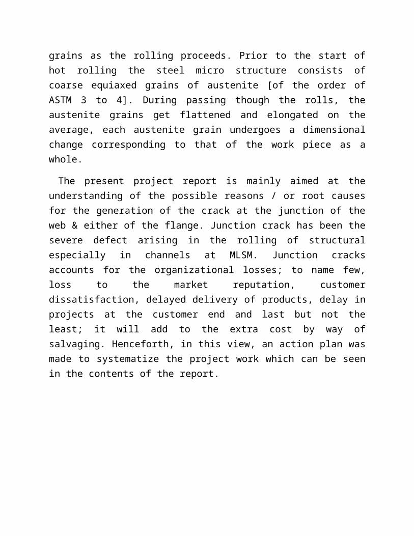
Hot rolling operation is one in which plastic deformation essentially has to take place above the recrystallisation temperature. In hot rolling the grain first deforms in the rolling direction, the deformed grains further recrystallise into a new set of smaller grains as the rolling proceeds. Prior to the start of hot rolling the steel micro structure consists of coarse equiaxed grains of austenite [of the order of ASTM 3 to 4]. During passing though the rolls, the austenite grains get flattened and elongated on the average, each austenite grain undergoes a dimensional change corresponding to that of the work piece as a whole.
The present project report is mainly aimed at the understanding of the possible reasons / or root causes for the generation of the crack at the junction of the web & either of the flange. Junction crack has been the severe defect arising in the rolling of structural especially in channels at MLSM. Junction cracks accounts for the organizational losses; to name few, loss to the market reputation, customer dissatisfaction, delayed delivery of products, delay in projects at the customer end and last but not the least; it will add to the extra cost by way of salvaging. Henceforth, in this view, an action plan was made to systematize the project work which can be seen in the contents of the report.
1. INTRODUCTION
MLSM Plant Layout
Supplier & Technology
• MILL : Danieli
• REHEATING FURNACE : Tenova
• HI-PROFILE : Technogamma
• MILL AUTOMATION : ABB (Asea Brown Baveri)
• CRANES (EOT) : Jindal Steel & Power Limited
• ENGG. CONSULTANTS : Korus Engg. Solutions
Salient Features of the Medium & Light Structural Mill
1.Continuous Structural Rolling Mill 8.Online Bundling & Strapping of Products 2.High Production Capacity 9.Rolling of Beams & Channels on

Universal Stands 3.Superior Quality Products 4.Automatic Minimum tension Control 5.Optimum Roll Pass Design 6.Cartridge type Stands 7.Wide range of Products
Raw Materials
The finished products are of three different grades i.e.
1 C-18
2 C-18MMn and
3 HT
And the main raw materials used in MLSM are given in table below:
Table: 1 Types of Raw Material Used & All Finished Sections produced
RAW MATERIAL SIZE FINISHED PRODUCT
BILLET 150x150mmANGLE 100 TO 130mm
CHANNEL 125, 150 mm
BLOOM 250x250mm
ANGLE 150 TO 200mm
CHANNEL 175mm, 200mm
BEAM (NPB)180mm,200mm
Sections of the Mill
1.5.1 Raw Material Yard:
The raw material yard is the area where generally all the input materials are kept / or stored for converting them into suitable products according to the end applications/ uses so that it can then be used in future as per the requirement of

the customers. The basic raw materials used in MLSM are described above in table1
Reheating Furnace:
This is the heart of any hot rolling mill where in the charge is heated to rolling temperature. Hence, the first and the vital step of hot rolling includes heating the raw material to sufficiently high temperature in order to minimize the flow stresses during subsequent rolling and ease the process of plastic deformation through rolling operation. The charge might be either in the form of billets or blooms. The type of furnace could be pusher type (where the raw materials are forced or pushed by subsequent material), walking hearth or walking beam – either top fired or top and bottom fired. The fuel used could be either oil or gas. The burners are located in a manner so as to achieve uniform heat distribution. The radiation heat energy is efficiently transferred through the useful heat transfer area created by the charge bed. The reheating furnace at MLSM-JSPL is a walking beam type furnace with a capacity of 200 ton/hour being installed by Tenova (Italy). The pushing mechanism of Pusher Type Furnace owes to the disadvantage of maintaining the sufficient gap between two adjacent charge materials. As the name suggest, in this type of furnace the raw material are loaded on heavy beams that move in manner resembling a step.
This movement is often referred to as a stroke. During the material movement inside the furnace the material first moves 100mm upwards, then 500mm forward followed by 200mm downward movement and then finally 500mm backward. This stroke tends to move the material into the furnace.
1.5.1.1 Construction of Reheating furnace:
The total length (refractory to refractory) of RHF is 28mt 800mm with a width of 12mt 800mm. The furnace is constructed with steel having a refractory lining of high alumina. Further some clearance is provided at each side of furnace so as to compensate for the expansion of raw material.
For charging higher thickness raw material as in case of blooms and slabs, burners are provided below and above the skids as against conventional furnaces where burners are provided only on the top. Hence it is known as top and bottom fired Reheating Furnace. There are total 58 burners utilized in the

furnace for the purpose of heating the raw input material. The steps of heating the raw material are:
Yard: All the input materials of all types & all grades from SMS are stored here for further processing in the Mill
Storage Table: The Raw material from the yard are then stored at storage table prior to charging.
Roller Table: The Raw material moves from storage table to loading table through roller assembly.
Loading Table: The raw material then passes through a small door by Pusher type mechanism as shown in the figure below which is then loaded on loading table one by one inside the furnace. It allows uniform heating of raw material with an added advantage of uniform load distribution on skids. The materials are generally charged in one/single row pattern. This type of charging or rather the type of door functioning has an advantage of the less drop in temperature as while charging the opening of the door is less.
Main Furnace: From the loading table the raw material is transferred to main furnace where they are heated up to the desired rolling temperature.
Discharging Roller Table: After the raw materials are heated up to the desired temperature, they are then ejected out of the furnace by the same kick-off mechanism. The Exit Raw material then moves to the De-scaler.
1.5.1.2 Zones of furnace
The furnace is basically divided into three zones namely preheating, heating and soaking zones. Manually, there are in total 4 zones where in the 4 th zone is Recuperative Zone. Our furnaces are highly fuel efficient due to proper roof profile / zonal distribution, optimum preheating / recuperative zone lengths, proper burner / flue port locations and good instrumentation including furnace chamber pressure control eliminating atmosphere air ingress, which also reduces the scale loss and decarburization of the charge.
Preheating zone

Heating zone
Soaking zone
Recuperative zone
In preheating zone the raw material are heated to certain predetermined temperature, however the actual heating takes place in the heating zone. However to ensure the uniformity of temperature up to the desired limits between the surface and core of raw material the material is kept hold in the soaking zone for a specified limit of time.
The waste/flue gases generated and have attained a sufficient temperature of nearly 900ºC move in a direction opposite to that of the charge thereby ensuring considerable amount of waste heat recovery by convection in the preheating zone, which is also termed as the recuperative zone. It is also called as Non-burner zone. It is rather getting heated up by the flue gases returning back by other three zones through ID Fan. The recuperator generally utilizes its sensible heat for the purpose of heating the incoming cold gas utilized in the furnace.
Schematic Representation of the MLSM-Reheating furnace
950-1050ᵒC1050-1150ᵒC1250ᵒC Recuperative / Non-burner zone

1.5.2.3 Zone wise distribution of burner
Zone Top side Bottom side TotalPreheating zone 5 5 10
Heating zone 8 8 16Soaking zone 24 8 32
The total number of skids on which the raw material is charged is 25 out of which up to Preheating zone 4 are moveable and 4 are fixed where as in soaking zone 4 are moveable and 5 are fixed. This is because the materials temperature is high and it needs certain support for not getting bend or to avoid between fsna skids k beech me disturbance in the movement of the materialskids These skids are water circulated in order of avoid overheating.
1.5.1.3 Type of charging
The raw material can be charged in furnace either in hot condition or in a cold condition Depending on this the furnace charging system can be categorized as
Cold charging
Hot charging
But in the reheating furnace of MLSM generally Cold charging is done.
1.5.2.5 Raw Materials and Zone wise temperature
Cold ChargingIdeal Temperatures Bloom (150x150) Bloom (250x250)
Soaking zoneUpper Soaking 1130±20 1220±20Lower Soaking 1130±20 1220±20
Heating zoneUpper Heating 1100±20 1180±20Lower Heating 1100±20 1180±20
Preheating zone 1030±20 1080±15Retention Time 1 hour 30 minutes 2 hour 30 minutes
Parameters
Water Compressed air
Instrument air Fuel oil
Combustion Air LPGInle Outle Flow Pressur Flow

t t e
Values 5 bar 2 bar500m³/
hr 7 bar 5 bar
300 Nm³/h
r 7 bar950
dapa(mmwc)2000 dapa
1.5.2.6 Firing System of RHF
In order to attain the desired temperature inside the furnace dual firing system is used in which a mixture of mixed gas (mixture of producer gas and LPG), heavy furnace oil & Light Diesel Oil are used. With this the atomizing air (for converting the oil having high density into the small droplets) & combustion air is also used. At first the PG is made on and then oil is used for lightning the burner. This is because the Producer gas is cheap.
Specific consumption is given below
Consumption (per day)
Producer gas (From PGP) 244000NMᶟHeavy Furnace Oil ( exported from outside) 5.55kL
Light Diesel Oil (LDO) 133 ltrs
1.5.2.7 Composition of fuel used in RHF
Heavy Furnace Oil
Carbon Sulphur Nitrogen Hydrogen Calorific value
84% 4% 1% 11% 9.8 MCal/Kg
Producer Gas
CO H2 CO2 N2 O2 CH4 Calorific Value
18% 19% 10% 48% 2% 3% 1.100 MCal/Nm3

1.5.2.8 Heat Transfer inside Furnace
At first, the heat generated by fuel is transferred to surrounding atmosphere through radiation then through the surrounding media the heat is transferred to the raw material through convection. Lastly, on atomic scale the heat is transferred through conduction.
Other Details
In case of charging Blooms of 150x150 mm size, maximum of 107 blooms are charged at a time inside the furnace (minimum of 100mm gap is maintained between adjacent blooms ) while maximum of 54 blooms are charged at a time inside the furnace ( here minimum of 250mm gap). The total numbers of material that can be charge inside the furnace is calculated as the ratio of furnace effective length to that of stroke length. Again the minimum gap to be maintained between two adjacent raw materials is give as the difference between the stroke length and the width of the raw material.
Total 26 thermocouples are installed inside the furnace including both S- type (1500–1700deg C) i.e. generally for high temperature measurement & K type (up to 700-1000deg C) i.e. rather for low temperature measurement. However the K – type thermocouple is mainly used in compressor & recuperator. In Zone 1, four thermocouples are used to detect the temperature of the particular area/atmosphere with in the furnace. In case of this always the thermocouple having/showing maximum value is noted. From Zone 2 and upto Zone 7 there are 2 thermocouples in each zone. Another 10 thermocouples are used in the Duct line. There are two types of thermocouples i.e. S and K types. Generally, S-type is used within the furnace where in the positive wire is of Platinum (Pt) and negative wire is of Platinum-Rhodium (Pt-Rh). In the similar way the positive wire in K-type is of Chromel and the negative wire is of Alumel In case of mill shut down, only PG gas is used for maintaining furnace temperature at 600-800 deg C (depending on the mill condition) and heavy fuel supply is stopped.
Process Data Furnace is divided in 7 zones

Manufacture & identificationTenova (L0IITALIMPIANTS) Preheating Zone(1) 10 Lateral Burner
Supplied ByTenova (L0IITALIMPIANTS) Top Heating Zone(2) 8 Lateral Burner
Commissioning Data 31st March 2010 Bottom Heating Zone(3) 8 Lateral Burner
TypeWalking beam furnace Top & Bottom Fired Top Soaking Right Zone(4) 12 Roof Radiant Burner
Capacity 200 Tons/Hour Top Soaking Left Zone(5) 12 Roof Radiant BurnerMax. Operating Temperature 1350ᵒC Bottom Soaking Right Zone(6) 4 Frontal BurnerMovement of Walking beam By Hydraulics Cylinder Bottom Soaking Left Zone(7) 4 Frontal Burner
Cylinder (Lifting,Shifting,Forward & Reverse)Lifting Stroke 200 MM Furnace Dimension
Shifting Stroke 250 MM Effective Length 27.8 MSkid Width 12.8 M
Vertical Post 4+4=8 Height 12 MHorizontal Post No. Of Moveable Post=5 Total Burner 58
Furnace having Basic 2 Types of System No. of tanks HFO=500kLHandling System LDO=20kL
Combustion System
Fluid Types of cooler water usedFuel Oil (HFO) Indirect Cooling Water Skid & Door
Fuel flow rate 7000 kg/hr Direct Cooling Water Camera, Jacket
Pressure at top 7 bar Cooling Waterfor instrumentation CCTV, Heat
exchanger
Temperature 90ºC at burnerLower Calorific Value 9800 kcal/kg Flow Rate 500 mm³/hr
Light Diesel Oil (LDO) Inlet Pressure 5 barLDO Flow rate 2200kg/hr Max Inlet Temperature 35ºC
Pressure at top 7 bar
Temperature Ambient Emergency Cooling WaterLower Calorific Value 10100kcal/kg Flow Rate 350 mm³/hr
LPG for Pilot Burner Pressure 3 barFlow Rate 8.10NM³/HR Max Inlet Temperature 40ºC
Pressure at top 2000 bar pH value 7 to 8
Temperature 20ºCProducer Gas (PG) Refractory Lining & Insulation

Flow Rate 5000NM³/HR Refractory Castable
Pressure at top 1200MMWC Plastic Refractory
Temperature at Top 50ºC MAX Anchor Bricks
Lower Calorific Value 1100KCL/NM³ Standard Bricks
Temperature 20ºC End Arch & others
Nitrogen For Purging
Flow Rate 5000 NM³/HR Combustion Control System
Pressure 2000 MN 2 No. of Combustion Air FanTemperature Ambient Type Centrifugal
Compressed Air for Atomizing Flow Rate 56500 NM³/HRFlow Rate 4000 NM³/HR Operating Pressure 800 dapa (MMWC)
Pressure 7 bar (MIN) 1 No. of Dilution FanTemperature Ambient Flow Rate 23000 NM³/HR
Type of Charging Single Row Operating Pressure 500 dapa (MMWC)(Right & Left Side) 1 No. of ID Fan
Descaler
After the material is discharged from the furnace, it is then passed to descaling unit where a high pressure water jet is targeted on the surface of raw material. . Due to high temperature prevailing inside the furnace and further with the addition of oxidizing atmosphere in the reheating furnace, mill scale is formed on the surface of the charge material. Mill scale, often shortened to just scale, is the flaky surface of hot rolled steel, iron oxides consisting of Iron (II, III) oxide, hematite, and magnetite. This mill scale should be removed as it causes surface defects in the finished rolled product.
Bloom Size (INPUT SIZE)Billet 130x130 mm 8.5m - 12mBloom 150x150 mm / 250x250 mm 8.5m - 12mBeam Blank 355x280x90 mm (463 kg/m) 8.5m - 12m

This descaling unit can produce a maximum pressure of 250 bars. From de scaling unit the raw material proceeds to Roughing Stands. It helps in improving the surface quality of finished products.
Roughing Mill
Here we have five continuous rolling stands that are arranged in horizontal and vertical mode (1H, 2V, 3H, 4H, 5V). In the roughing mill stands the blooms are reshaped to a preliminary section to be rolled. Maximum change in cross-section area takes place in these roughing stands. The roll stand is designed for a rolling force of ___tons.
The roll stand consists of 2 closed top housings which are connected by top and bottom crossheads and fixed on bed plates. Pressure screws are arranged to maintain the desired roll gap.
A pass schedule is prepared and maintained by the mill operator. It consists of various parameters like Pass layout, roll gap, entry speed, rolling speed, kick-off speed and draft for different cross-sections. However there are manipulators like guides & stripper that guide the raw material into the roll gap. The maximum limit of thickness reduction is 60%.
Table by Danieli
Finishing Mill
In finishing mill there are ten continuous stands which are arranged in universal or horizontal manner (6H, 7H/U, 8H/U, 9H/U, 10H/U, 11H, 12H/U, 13H/U, 14H, 15H/U) according to the product to be rolled. Here the reduction ratio is comparatively less than the roughing mill as because there is a regular temperature drop in the material along previous passes and an extra/excessive load is needed to be applied which may increase the stresses within the material and may lead to some problems. Like, as if we see in channels or in beams the junction of web & either of the flange thickness vary from toe to root and it is also clear that the junction portion is thicker than the other area of the structural part i.e. there might be some temperature gradient in that region and it may be stressed also. In this type of case if further stresses will increase then it will increase the tendency of the defects. Here the contact of the material with the rolls is more.

Also, the reduction amount in particular stand depends on various factor and they are
What we are rolling
What type of grade is going to be rolled?
What is the composition of the raw material?
What is the effect of temperature on the above described raw material?
On the basis of all this the pressure/load to be given is decided
Due to these things how will it affect the elongation & spread in any material.
Also, rolling speed is decided accordingly.
Last but not the least the type of motor, gear and what are their capacities is identified.
Technogamma
It provides online dimensions of the hot rolled sections. It is a kind of laser measuring device, used for dimensional inspection of hot section without any physical contact.
Profile
Here the sample is taken from the cooling bed and inspected whether the structural section produced is in accordance with IS standards or not. Also, all the dimensions are checked and written.
Cooling Bed It is a walking beam type of bed.
Length = 90m
Width = 18m
Cooling of the bars is done by natural air and water spray.

Straightening Machine
Its basic purpose is to straighten the cooled sections. There are 10 rolls in it where in 5 rolls are on the upper side and 5 rolls are on the down side.
Cold Saws
Its main purpose is to cut the rolled sections according to the required length. There are 2 no. of cold saws. There are 2 saws as because for highest production both can be used alternately.
Stacker & Tying Machine
It is used for the circumferential wire binding of the stacks.
Collecting Bay
It is used for collecting the bundles. Bundles are color coded here. From here bundles are transferred to yard.
Products
View of the products at MLSM

The list of products of the MLSM which are covered in BIS is given as follows:
S.No Section Covered in BIS (License) Product StatusEqual Leg Angle
1 ISA 100X100X6 Available Rolled2 ISA 100X100X7 Available Rolled3 ISA 100X100X8 Available Rolled4 ISA 100X100X10 Available Rolled5 ISA 100X100X12 Available Rolled6 ISA 100X100X15 Available Not RolledYet7 ISA 110X110X8 Available Rolled8 ISA 110X110X10 Available Rolled9 ISA 110X110X12 Available Rolled10 ISA 110X110X16 Available Rolled11 ISA 120X120X8 Available Rolled12 ISA 120X120X10 Available Rolled13 ISA 120X120X12 Available Not RolledYet14 ISA 120X120X15 Available Not RolledYet15 ISA 130X130X8 Available Rolled16 ISA 130X130X9 Available Not RolledYet17 ISA 130X130X10 Available Rolled

18 ISA 130X130X12 Available Rolled19 ISA 130X130X16 Available Rolled20 ISA 150X150X10 Available Rolled21 ISA 150X150X12 Available Rolled22 ISA 150X150X15 Available Rolled23 ISA 150X150X16 Available Rolled24 ISA 150X150X18 Available Rolled25 ISA 150X150X20 Available Rolled26 ISA 180X180X15 Available Not RolledYet27 ISA 180X180X18 Available Not RolledYet28 ISA 180X180X20 Available Not RolledYet29 ISA 200X200X12 Available Rolled30 ISA 200X200X16 Available Rolled31 ISA 200X200X20 Available Rolled32 ISA 200X200X18 Not covered in BIS Rolled33 ISA 200X200X24 Available Rolled34 ISA 200X200X25 Available Rolled
Parallel Flange Beam
1NPB200X100X18.4
2 Available Rolled
2NPB200X100X22.3
6 Available Rolled
3NPB200X100X25.0
9 Available Rolled4 NPB 180X90X21.27 Available Rolled5 NPB 180X90X18.80 Available Rolled6 NPB 180X90X15.37 Available Rolled
Channel1 200X75X22.3 Available Rolled2 175X75X19.6 Available Rolled3 150X75X16.8 Available Rolled4 125X65X13.1 Available Rolled5 125X66 Available Not RolledYet6 100X50 Available Not RolledYet7 75X40 Available Not RolledYet
Product Application / End Uses
1. Power Sector 2.Infrastructure constructions 3.Cement & Steel Plant Construction 4. Transmission line tower / telecom line towers

5. Fabrication 6. Bus / truck bodies 7. Electrical towers (SEB / Railways) 8. Industrial sheds 9. Commercial & Industrial Houses
Standards followed for rolling of structurals in MLSM
Certification 1. ISO 9001, ISO 14001 & OHSAS 18001:2007. 2. BIS certification for all sections. 3. PGCIL for all Angle sections.