mixer manual - cole-parmer · mixer manual instructions installation operation maintenance ship to...
TRANSCRIPT
MIXER MANUAL
INSTRUCTIONS
INSTALLATION
OPERATION
MAINTENANCE
Ship To Customer:Bill To Customer:PO Number:Model:Order Number:Line Number:
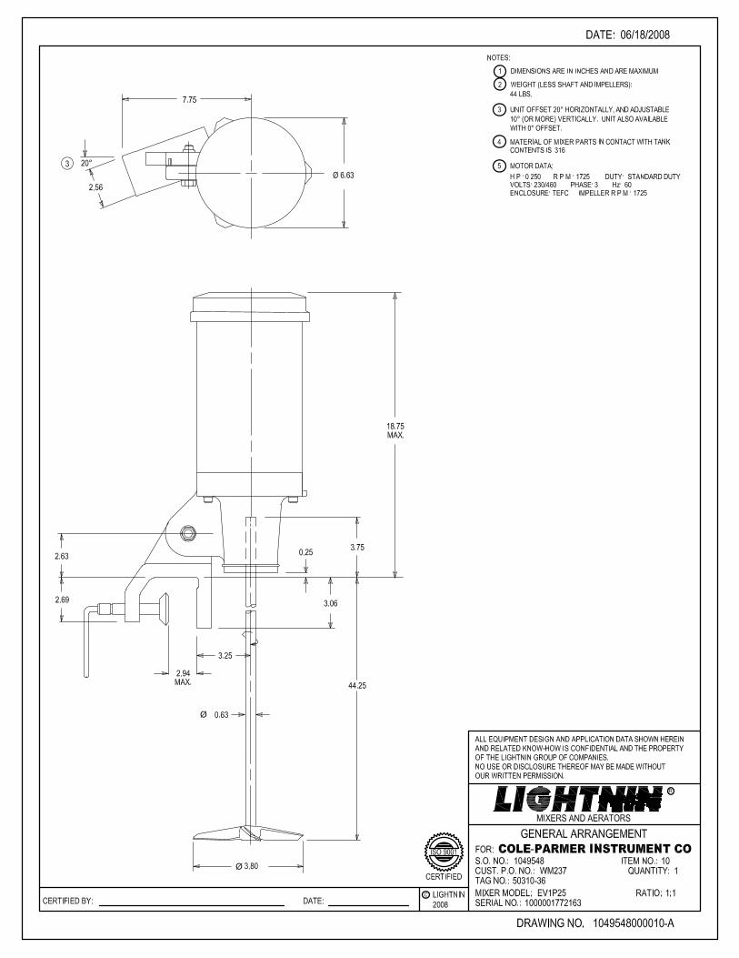
COLE-PARMER INSTRUMENT COMPANYCOLE-PARMER INSTRUMENT COWM237Lightnin Mixer Model EV1P250001049548000010
Tagging:
50310-36
INSTRUCTION MANUALLIGHTNIN SALES ORDER 0001049548
LIGHTNIN LINE ITEM 000010
TABLE OF CONTENTS
Safety Check List GENERAL ARRANGEMENT DRAWING Machine Assembly Drawing General Instructions Motor Electric Instructions A310 (1 piece) Impeller Assembly Sales Offices
IT-2144 1049548000010-A L-17094 IT-3694 IT-2588 L-16701 IT-3839
DOCUMENT NO.TITLE
REVISION
2007
DATE 5–9–86
REVISED 05–14–07 PAGE 1 OF 2
INST. NO. IT–2144G
© LIGHTNINLIGHTNINMIXERS AND AERATORS
®
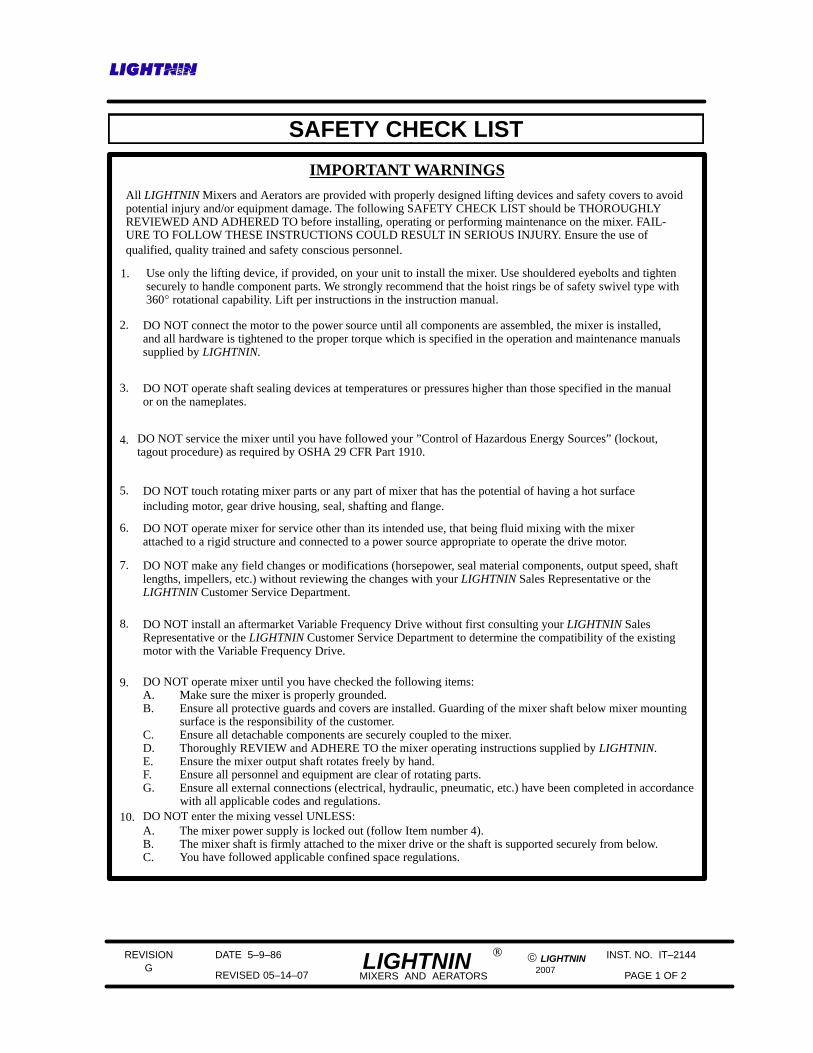
SAFETY CHECK LIST
IMPORTANT WARNINGSAll LIGHTNIN Mixers and Aerators are provided with properly designed lifting devices and safety covers to avoidpotential injury and/or equipment damage. The following SAFETY CHECK LIST should be THOROUGHLY REVIEWED AND ADHERED TO before installing, operating or performing maintenance on the mixer. FAIL-URE TO FOLLOW THESE INSTRUCTIONS COULD RESULT IN SERIOUS INJURY. Ensure the use ofqualified, quality trained and safety conscious personnel.
2. DO NOT connect the motor to the power source until all components are assembled, the mixer is installed,and all hardware is tightened to the proper torque which is specified in the operation and maintenance manualssupplied by LIGHTNIN.
3. DO NOT operate shaft sealing devices at temperatures or pressures higher than those specified in the manualor on the nameplates.
4. DO NOT service the mixer until you have followed your ”Control of Hazardous Energy Sources” (lockout,tagout procedure) as required by OSHA 29 CFR Part 1910.
5. DO NOT touch rotating mixer parts or any part of mixer that has the potential of having a hot surfaceincluding motor, gear drive housing, seal, shafting and flange.
6. DO NOT operate mixer for service other than its intended use, that being fluid mixing with the mixer attached to a rigid structure and connected to a power source appropriate to operate the drive motor.
7. DO NOT make any field changes or modifications (horsepower, seal material components, output speed, shaftlengths, impellers, etc.) without reviewing the changes with your LIGHTNIN Sales Representative or theLIGHTNIN Customer Service Department.
9. DO NOT operate mixer until you have checked the following items:A. Make sure the mixer is properly grounded.B. Ensure all protective guards and covers are installed. Guarding of the mixer shaft below mixer mounting surface is the responsibility of the customer.C. Ensure all detachable components are securely coupled to the mixer.D. Thoroughly REVIEW and ADHERE TO the mixer operating instructions supplied by LIGHTNIN.E. Ensure the mixer output shaft rotates freely by hand.F. Ensure all personnel and equipment are clear of rotating parts.G. Ensure all external connections (electrical, hydraulic, pneumatic, etc.) have been completed in accordance with all applicable codes and regulations.DO NOT enter the mixing vessel UNLESS:10.A. The mixer power supply is locked out (follow Item number 4).B. The mixer shaft is firmly attached to the mixer drive or the shaft is supported securely from below.C. You have followed applicable confined space regulations.
8. DO NOT install an aftermarket Variable Frequency Drive without first consulting your LIGHTNIN SalesRepresentative or the LIGHTNIN Customer Service Department to determine the compatibility of the existingmotor with the Variable Frequency Drive.
Use only the lifting device, if provided, on your unit to install the mixer. Use shouldered eyebolts and tightensecurely to handle component parts. We strongly recommend that the hoist rings be of safety swivel type with360° rotational capability. Lift per instructions in the instruction manual.
1.
REVISION
2007
DATE 5–9–86
REVISED 05–14–07 PAGE 2 OF 2
INST. NO. IT–2144G
© LIGHTNINLIGHTNINMIXERS AND AERATORS
®
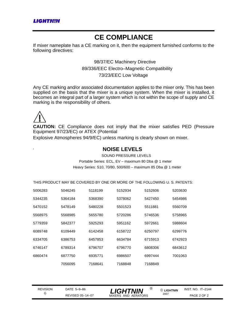
CE COMPLIANCEIf mixer nameplate has a CE marking on it, then the equipment furnished conforms to thefollowing directives:
98/37/EC Machinery Directive
89/336/EEC Electro–Magnetic Compatibility 73/23/EEC Low Voltage
Any CE marking and/or associated documentation applies to the mixer only. This has beensupplied on the basis that the mixer is a unique system. When the mixer is installed, itbecomes an integral part of a larger system which is not within the scope of supply and CEmarking is the responsibility of others.
CAUTION: CE Compliance does not imply that the mixer satisfies PED (PressureEquipment 97/23/EC) or ATEX (PotentialExplosive Atmospheres 94/9/EC) unless marking is clearly shown on mixer.
‘ NOISE LEVELS SOUND PRESSURE LEVELS
Portable Series: ECL, EV – maximum 80 Dba @ 1 meter
Heavy Series: S10, 70/80, 500/600 – maximum 85 Dba @ 1 meter
THIS PRODUCT MAY BE COVERED BY ONE OR MORE OF THE FOLLOWING U. S. PATENTS:
5006283 5046245 5118199 5152934 5152606 5203630
5344235 5364184 5368390 5378062 5427450 5454986
5470152 5478149 5480228 5501523 5511881 5560709
5568975 5568985 5655780 5720286 5746536 5758965
5779359 5842377 5925293 5951162 5972661 5988604
6089748 6109449 6142458 6158722 6250797 6299776
6334705 6386753 6457853 6634784 6715913 6742923
6746147 6789314 6796707 6796770 6808306 6843612
6860474 6877750 6935771 6986507 6997444 7001063
7056095 7168641 7168848 7168849
REVISION
1996
DATE 5-15-95
REVISED 3-18-96 PAGE 1 OF 6
INST. NO. IT-3694A
© LIGHTNINLIGHTNINMIXERS AND AERATORS
®
GENERAL INSTRUCTIONS“EV” SERIES DIRECT DRIVE MIXERS
SECTION 1 - INITIAL INSPECTION, SHIPPING ARRANGEMENTS1.1 Check the shipping crates and your LIGHTNIN equipment for possible shipping damage. Report any damage
immediately to the carrier and our factory.
1.2 The mixer and impellers are packed together. The mixer shaft, if over 48 inches long, is packed in a separatecontainer.
1.3 Do not remove any protective coatings or wrappings until the mixer is ready to be put into service. If the mixeris to be stored, store only in an indoor, clean, dry location with controlled temperatures of 15° C to 40° C (59° F to 104° F).
SECTION 2 - MIXER INSTALLATION2.1 Refer to Installation drawing for:
a . Proper mixer mounting and location.
b . Proper minimum impeller off-bottom and relative spacing for dual impeller applications.
2.2 Lock-out power before positioning mixer, and review safety instructions before starting mixer.
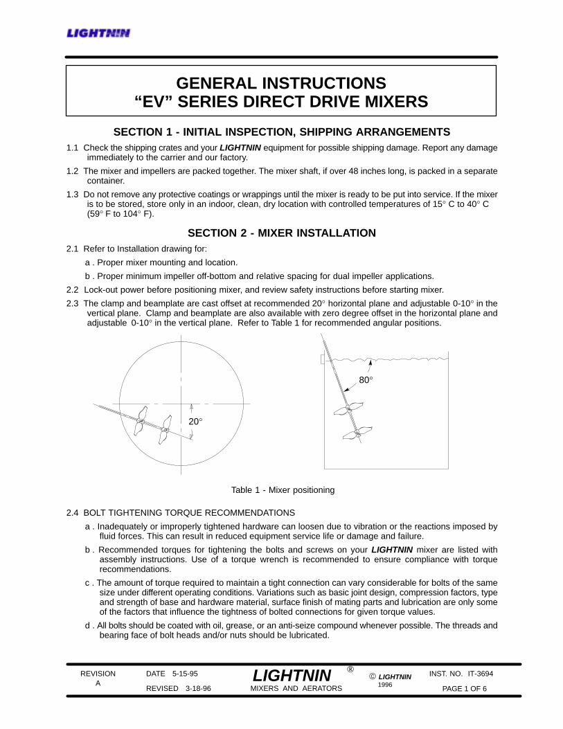
2.3 The clamp and beamplate are cast offset at recommended 20° horizontal plane and adjustable 0-10° in thevertical plane. Clamp and beamplate are also available with zero degree offset in the horizontal plane andadjustable 0-10° in the vertical plane. Refer to Table 1 for recommended angular positions.
Table 1 - Mixer positioning
20°
80°
2.4 BOLT TIGHTENING TORQUE RECOMMENDATIONS
a . Inadequately or improperly tightened hardware can loosen due to vibration or the reactions imposed byfluid forces. This can result in reduced equipment service life or damage and failure.
b . Recommended torques for tightening the bolts and screws on your LIGHTNIN mixer are listed withassembly instructions. Use of a torque wrench is recommended to ensure compliance with torquerecommendations.
c . The amount of torque required to maintain a tight connection can vary considerable for bolts of the samesize under different operating conditions. Variations such as basic joint design, compression factors, typeand strength of base and hardware material, surface finish of mating parts and lubrication are only someof the factors that influence the tightness of bolted connections for given torque values.
d . All bolts should be coated with oil, grease, or an anti-seize compound whenever possible. The threads andbearing face of bolt heads and/or nuts should be lubricated.
REVISION
1996
DATE 5-15-95
REVISED 3-18-96 PAGE 2 OF 6
INST. NO. IT-3694A
© LIGHTNINLIGHTNINMIXERS AND AERATORS
®
e . ALL BOLTS SHOULD BE RETIGHTENED AFTER THE UNIT HAS BEEN RUN UNDER LOAD FORTWO (2) WEEKS, AND AT EACH SCHEDULED SHUT-DOWN THEREAFTER.
f . Unless otherwise specified, it is recommended that metric commercial standard class 8.8 bolts and screws,and class 8 nuts be used for all bolted connections. For inch hardware use GR5.
SECTION 3 - SHAFT AND IMPELLER INSTALLATION3.1 Install the impeller(s) on the mixer shaft (231) by tightening the set screws in the impeller hub. Refer to the
installation drawing for recommended dual impeller spacing if two impellers are supplied. Refer to ImpellerAssembly drawing for general impeller orientation.
3.2 Clean the mixer shaft (231) end and drive quill (51) thoroughly.
3.3 Orient the drive quill so that the set screw (58) aligns with the hole in the bearing housing (36). Align quill shaftby inserting lower shaft (231) into quill and rotate quill manually.
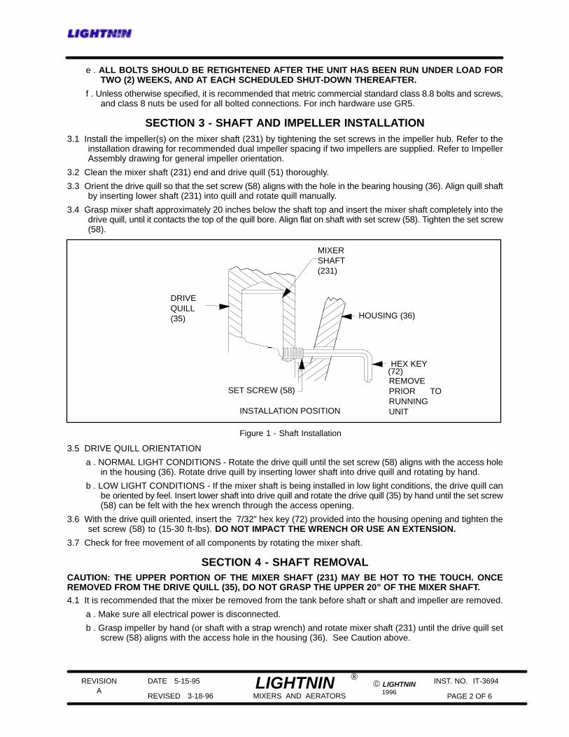
3.4 Grasp mixer shaft approximately 20 inches below the shaft top and insert the mixer shaft completely into thedrive quill, until it contacts the top of the quill bore. Align flat on shaft with set screw (58). Tighten the set screw(58).
SET SCREW (58)
HEX KEY(72)
MIXERSHAFT(231)
HOUSING (36)
DRIVEQUILL(35)
REMOVEPRIOR TORUNNINGUNITINSTALLATION POSITION
Figure 1 - Shaft Installation
3.5 DRIVE QUILL ORIENTATION
a . NORMAL LIGHT CONDITIONS - Rotate the drive quill until the set screw (58) aligns with the access holein the housing (36). Rotate drive quill by inserting lower shaft into drive quill and rotating by hand.
b . LOW LIGHT CONDITIONS - If the mixer shaft is being installed in low light conditions, the drive quill canbe oriented by feel. Insert lower shaft into drive quill and rotate the drive quill (35) by hand until the set screw(58) can be felt with the hex wrench through the access opening.
3.6 With the drive quill oriented, insert the 7/32” hex key (72) provided into the housing opening and tighten theset screw (58) to (15-30 ft-lbs). DO NOT IMPACT THE WRENCH OR USE AN EXTENSION.
3.7 Check for free movement of all components by rotating the mixer shaft.
SECTION 4 - SHAFT REMOVALCAUTION: THE UPPER PORTION OF THE MIXER SHAFT (231) MAY BE HOT TO THE TOUCH. ONCEREMOVED FROM THE DRIVE QUILL (35), DO NOT GRASP THE UPPER 20” OF THE MIXER SHAFT.4.1 It is recommended that the mixer be removed from the tank before shaft or shaft and impeller are removed.
a . Make sure all electrical power is disconnected.
b . Grasp impeller by hand (or shaft with a strap wrench) and rotate mixer shaft (231) until the drive quill setscrew (58) aligns with the access hole in the housing (36). See Caution above.
REVISION
1996
DATE 5-15-95
REVISED 3-18-96 PAGE 3 OF 6
INST. NO. IT-3694A
© LIGHTNINLIGHTNINMIXERS AND AERATORS
®
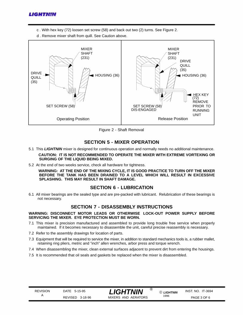
c . With hex key (72) loosen set screw (58) and back out two (2) turns. See Figure 2.
d . Remove mixer shaft from quill. See Caution above.
SET SCREW (58)
HEX KEY
Figure 2 - Shaft Removal
(72)
MIXERSHAFT(231)
HOUSING (36)
DRIVEQUILL(35)
REMOVEPRIOR TORUNNINGUNIT
SET SCREW (58)
MIXERSHAFT(231)
HOUSING (36)DRIVEQUILL(35)
Operating Position Release Position
DIS-ENGAGED
SECTION 5 - MIXER OPERATION5.1 This LIGHTNIN mixer is designed for continuous operation and normally needs no additional maintenance.
CAUTION: IT IS NOT RECOMMENDED TO OPERATE THE MIXER WITH EXTREME VORTEXING ORSURGING OF THE LIQUID BEING MIXED.
5.2 At the end of two weeks service, check all hardware for tightness.
WARNING: AT THE END OF THE MIXING CYCLE, IT IS GOOD PRACTICE TO TURN OFF THE MIXERBEFORE THE TANK HAS BEEN DRAINED TO A LEVEL WHICH WILL RESULT IN EXCESSIVESPLASHING. THIS MAY RESULT IN SHAFT DAMAGE.
SECTION 6 - LUBRICATION6.1 All mixer bearings are the sealed type and are pre-packed with lubricant. Relubrication of these bearings is
not necessary.
SECTION 7 - DISASSEMBLY INSTRUCTIONSWARNING: DISCONNECT MOTOR LEADS OR OTHERWISE LOCK-OUT POWER SUPPLY BEFORESERVICING THE MIXER. EYE PROTECTION MUST BE WORN.7.1 This mixer is precision manufactured and assembled to provide long trouble free service when properly
maintained. If it becomes necessary to disassemble the unit, careful precise reassembly is necessary.
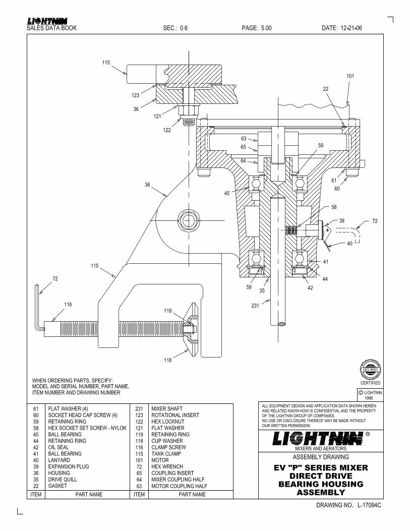
7.2 Refer to the assembly drawings for location of parts.
7.3 Equipment that will be required to service the mixer, in addition to standard mechanics tools is, a rubber mallet,retaining ring pliers, metric and ”inch” allen wrenches, arbor press and torque wrench.
7.4 When disassembling the mixer, clean external surfaces adjacent to prevent dirt from entering the housings.
7.5 It is recommended that oil seals and gaskets be replaced when the mixer is disassembled.
REVISION
1996
DATE 5-15-95
REVISED 3-18-96 PAGE 4 OF 6
INST. NO. IT-3694A
© LIGHTNINLIGHTNINMIXERS AND AERATORS
®
7.6 SEAL REPLACEMENT
Inspect oil seals and gaskets for nicks, gouges and deformities. When replacing seals:
a . Coat the lips of seals with bearing grease.
b . Install oil seal with lip facing up as shown in Figure 3.
c . Coat the section of shaft sealing surface with oil.
7.7 BEARING REPLACEMENT
a . Old bearings can be removed with a puller or an arbor press.
b . New bearings can be pressed on the shafts. Be careful to apply load only to the inner race.
c . Make sure the bearings are tightly seated against the shaft or housing shoulders with no clearance.
7.8 SHAFT REMOVAL
Loosen set screw (58) and remove mixer shaft (231) as outlined in Section 4.
7.9 MOTOR REMOVAL
a . Remove the mixer from the tank and remove the mixer shaft (231) as outlined in Section 4.
b . Tip the mixer upside down on a workbench.
c . Remove the four socket head cap screws (60) holding the bearing housing (36) to the motor (101).
d . Lift the bearing housing off the motor. It may be necessary to tap the bearing housing GENTLY with a rubbermallet to get the bearing housing to separate from the motor.
e . Remove motor coupling half (63) and insert (65) from motor shaft.
7.10 BEARING MODULE DISASSEMBLY
a . Remove the oil seal (42) from the drive quill (35). This oil seal will be damaged and a new oil seal mustbe installed when reassembled.
b . Remove retaining ring (44).
c . Remove upper retaining ring (59).
d . Place the bearing housing upright in a press, and press out the drive quill (35) and lower bearing (41).
e . Remove lower retaining ring (59) and bearing (41) from the drive quill (35).
f . Remove upper bearing (41) from housing (36).
g . Inspect bearing (41) for excessive wear. Replace if necessary.
SECTION 8 - ASSEMBLY INSTRUCTIONS8.1 QUILL ASSEMBLY
Insert the set screw (58) into the drive quill (35) until it is flush with the bore of the quill.
8.2 BEARING MODULE ASSEMBLY
a . Press the lower bearing (41) onto the drive quill (35) bearing journal. The bearing must seat against thedrive quill shaft shoulder with no visible gap.
b . Install the lower external retaining ring (59).
c . Press the drive quill assembly into the bearing housing (36) from the bottom until the bearing seats on thehousing shoulder.
d . Install lower retaining ring (44).
e . Press oil seal (42) in place with the seal cavity facing as shown in Figure 3. Make sure the oil seal has theinternal spring removed. This is a non-lubricated seal, and will run hot and have a shortened life if thespring is not removed.
f . Turn the bearing housing over, support the assembly on the quill shaft (35) and install the upper bearing(45) by pressing it into the bearing housing and onto the quill shaft.
REVISION
1996
DATE 5-15-95
REVISED 3-18-96 PAGE 5 OF 6
INST. NO. IT-3694A
© LIGHTNINLIGHTNINMIXERS AND AERATORS
®
g . Install the upper retaining ring (59).
h . Support the bearing housing assembly in an upright position and press the drive quill downward until thebearing (41) shoulders on the retaining ring (59). This will relieve any locked in axial load on the bearingcreated during assembly.
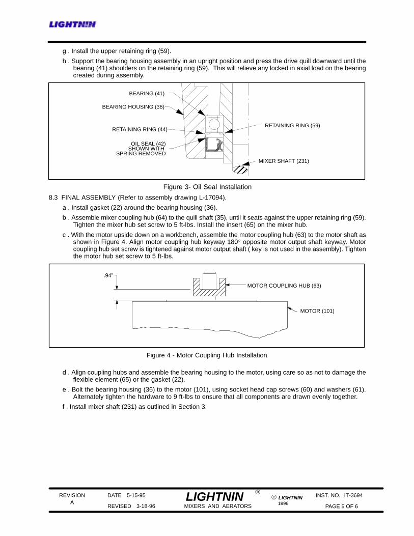
Figure 3- Oil Seal Installation
BEARING (41)
RETAINING RING (59)
OIL SEAL (42)SHOWN WITH
SPRING REMOVED
BEARING HOUSING (36)
MIXER SHAFT (231)
RETAINING RING (44)
8.3 FINAL ASSEMBLY (Refer to assembly drawing L-17094).
a . Install gasket (22) around the bearing housing (36).
b . Assemble mixer coupling hub (64) to the quill shaft (35), until it seats against the upper retaining ring (59).Tighten the mixer hub set screw to 5 ft-lbs. Install the insert (65) on the mixer hub.
c . With the motor upside down on a workbench, assemble the motor coupling hub (63) to the motor shaft asshown in Figure 4. Align motor coupling hub keyway 180° opposite motor output shaft keyway. Motorcoupling hub set screw is tightened against motor output shaft ( key is not used in the assembly). Tightenthe motor hub set screw to 5 ft-lbs.
Figure 4 - Motor Coupling Hub Installation
MOTOR (101)
.94”
MOTOR COUPLING HUB (63)
d . Align coupling hubs and assemble the bearing housing to the motor, using care so as not to damage theflexible element (65) or the gasket (22).
e . Bolt the bearing housing (36) to the motor (101), using socket head cap screws (60) and washers (61).Alternately tighten the hardware to 9 ft-lbs to ensure that all components are drawn evenly together.
f . Install mixer shaft (231) as outlined in Section 3.
REVISION
1996
DATE 5-15-95
REVISED 3-18-96 PAGE 6 OF 6
INST. NO. IT-3694A
© LIGHTNINLIGHTNINMIXERS AND AERATORS
®
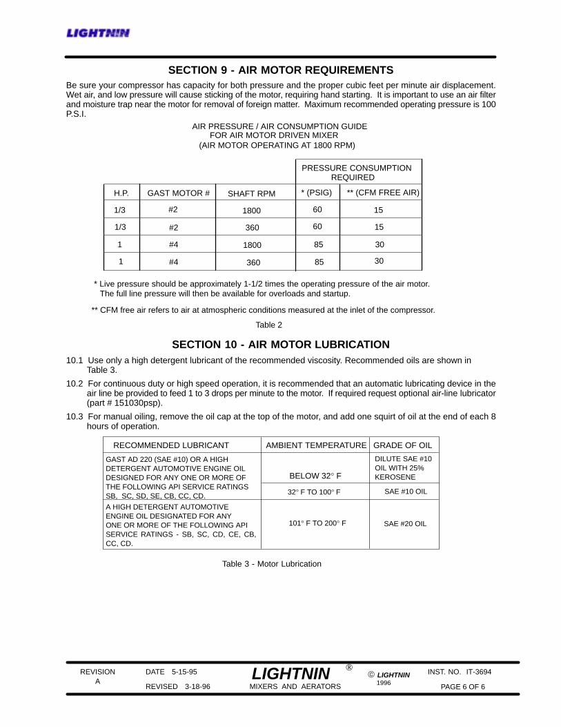
SECTION 9 - AIR MOTOR REQUIREMENTSBe sure your compressor has capacity for both pressure and the proper cubic feet per minute air displacement.Wet air, and low pressure will cause sticking of the motor, requiring hand starting. It is important to use an air filterand moisture trap near the motor for removal of foreign matter. Maximum recommended operating pressure is 100P.S.I.
AIR PRESSURE / AIR CONSUMPTION GUIDEFOR AIR MOTOR DRIVEN MIXER
(AIR MOTOR OPERATING AT 1800 RPM)
H.P. GAST MOTOR # SHAFT RPM
REQUIREDPRESSURE CONSUMPTION
** (CFM FREE AIR)* (PSIG)
1/3
1/3
1
1
#2
#2
#4
#4
1800
360
1800
360
60
60
85
85
15
15
30
30
Table 2
* Live pressure should be approximately 1-1/2 times the operating pressure of the air motor.The full line pressure will then be available for overloads and startup.
** CFM free air refers to air at atmospheric conditions measured at the inlet of the compressor.
SECTION 10 - AIR MOTOR LUBRICATION10.1 Use only a high detergent lubricant of the recommended viscosity. Recommended oils are shown in
Table 3.
10.2 For continuous duty or high speed operation, it is recommended that an automatic lubricating device in theair line be provided to feed 1 to 3 drops per minute to the motor. If required request optional air-line lubricator(part # 151030psp).
10.3 For manual oiling, remove the oil cap at the top of the motor, and add one squirt of oil at the end of each 8hours of operation.
RECOMMENDED LUBRICANT AMBIENT TEMPERATURE GRADE OF OIL
GAST AD 220 (SAE #10) OR A HIGHDETERGENT AUTOMOTIVE ENGINE OILDESIGNED FOR ANY ONE OR MORE OF THE FOLLOWING API SERVICE RATINGSSB, SC, SD, SE, CB, CC, CD.
A HIGH DETERGENT AUTOMOTIVE ENGINE OIL DESIGNATED FOR ANYONE OR MORE OF THE FOLLOWING APISERVICE RATINGS - SB, SC, CD, CE, CB,CC, CD.
BELOW 32° F
32° F TO 100° F
101° F TO 200° F
DILUTE SAE #10OIL WITH 25%KEROSENE
SAE #10 OIL
SAE #20 OIL
Table 3 - Motor Lubrication
LIGHTNINMIXERS AND AERATORS
REVISION
1991
DATE 11--30--91
REVISED 12--31--91 PAGE 1 OF 3
INST. NO. IT-2588
ALIGHTNIN
ELECTRIC MOTOR
INSTRUCTIONS
SECTION 1 -- INITIAL INSPECTION
1.1 Care is taken at the factory to assure that the motor arrives at its destination in first class condition. Ifthere is evidence of rough handling or damage in shipment, file a claim at oncewith the carrier andnotifyour factory.
Examine the outside of the motor carefully for damage, with particular attention to the conduit box, fansand covers. Check nameplate for correct speed, kilowatt, voltage, hertz and phase for conformancewith power supply. See Section 1.3 for warning on explosion--proof motors.
1.2 GENERAL DATA:
a .Single phase totally enclosed motors are wired at our factory for correct rotation.
b .All three phase and explosion-proof motors must be field wired for proper rotation. If rotationdoes not agree with nameplate, reverse any two line leads.
c .Dual voltage motors must be wired for the desired voltage. Refer to the connection diagramsprovided on the motor nameplate, inside the conduit box cover or in this manual.
d .Refer to Section 2 for motor maintenance and storage instructions.
1.3 WARNING
EXPLOSION--PROOF MOTORS -- These motors are constructed to comply with the U.L. LabelService Proceduremanual. When repairing and reassembling amotor that has anUnderwriter’s Label,it is imperative that the unit be reinspected and;
a .All original fits and tolerances must be maintained
b .All plugs and hardware to be securely fastened
c .Any part replacements, including hardware, be accurate duplicates of the originals
REPAIR WORK ON EXPLOSION--PROOF MOTORS CAN ONLY BE DONE BY THE ORIGINAL
MANUFACTURER. VIOLATIONS OF ANY OF THE ABOVE ITEMS WILL INVALIDATE THE
SIGNIFICANCE OF THE U.L. LABEL.
EXPLOSION-PROOF MOTORS ARE EQUIPPED WITH AN INTERNAL CIRCUIT INTERRUPTING
DEVICE WHICH TRIPS WHEN OVER HEATING OCCURS. THIS THERMAL PROTECTION CIRCUIT
WILL RESET AUTOMATICALLY WHEN UNIT COOLS.
If the thermal protector continues to trip, some abnormal condition exists. This conditionmust be correctedbefore motor will operate normally.
ALWAYS DISCONNECT POWER LINE BEFORE SERVICING ANY PART OF THEMIXER. Unexpectedmotor start-up may occur after the thermal protection circuit trips.
1.4 After unpacking and inspection to see that all parts are in good condition, turn the shaft by hand to besure there are no obstructions to free rotation. Equipment which has been in storage should be testedprior to being put into service.
a .It is best to check the insulation resistance of the stator winding with a megohmeter. If
resistance is lower than one megaohm, consult LIGHTNINR.
b .Motors are shipped from the factory with sealed, shielded bearings properly packed withgrease and ready to operate. Bearings are not regreaseable.
LIGHTNINMIXERS AND AERATORS
REVISION
1991
DATE 11--30--91
REVISED 12--31--91 PAGE 2 OF 3
INST. NO. IT-2588
ALIGHTNIN
1.5 WIRING -- Examine the nameplate data to see that it agrees with the power circuit to which the motoris to be connected. The motor is guaranteed to operate successfully with frequency not more than 5%and voltage not more than 10% above or below the nameplate data, or combined variation of voltageand frequency of not more than 10% above or below nameplate data. Efficiency, power factor andcurrent may vary from nameplate data.
1.6 Connect the motor leads to a power source that matches the line voltage and wiring diagram specifiedon the motor nameplate.
1.7 Check impeller shaft rotation by jogging the motor until it is determined that rotation is correct.
1.8 CAUTION
Repeated trial starts can overheat the motor (particularly for across-the-line starting). If repeated trialstarts aremade, allowsufficient timebetween trials to permit heat to dissipate from thewindings or rotorto prevent overheating. Starting currents are several times running currents, and heating varies as thesquare of the current. Do not exceed 12 starts per hour.
1.9 WARNING
The frames and other metal exteriors of motors should be grounded to limit their potential to groundin the event of accidental connection or contact between live electrical parts and the metal exteriors.All motors should be grounded through the conduit box. Explosion--proof motors have an integralground lead for grounding.
1.10 WARNING
Before startingmotor, remove all unused shaft keys and loose rotating parts to prevent them from flyingoff.
1.11 Startmotor and operate at minimum load prior to filling the tank or basin. Look for any unusual condition.
The motor should run smoothly with little noise. If the motor should fail to start and produces a decidedhum, it may be that the load is too great for the motor or that it has been connected improperly. Shutdown immediately and investigate for trouble.
SECTION 2 -- MOTOR MAINTENANCE AND STORAGE
Electric motors or other prime movers are not prepared by LIGHTNINR for indoor storage beyond 12months in a dry ambient atmosphere with controlled temperatures, or 6 months in a dry ambientatmosphere with no temperature control. OUTDOOR STORAGE OF ELECTRIC MOTORS IS NOTRECOMMENDED BY ANY MOTOR MANUFACTURER. For information on storage periods beyond
those shown, consult LIGHTNINR.
2.1 To insure continued reliable operation of electric motors, the following basic rule applies: KEEP THE
MOTOR CLEAN AND DRY. Motors should be inspected, and output shaft rotated, at a minimum of 6month intervals with increased frequency as needed depending upon the type of motor and the service.
2.2 Terminal connections and assembly hardware may loosen from vibration during service and should betightened.
2.3 Insulation resistance should be checked at operative temperature and humidity conditions to determinepossible deterioration of insulation due to excessive moisture or extremes in operating environment. Ifwide variations are detected, motors should be reconditioned.
2.4 LUBRICATION - The ball bearing has deep grooved, double shielded sealed bearings with sufficientlubricant packed into the bearings by the manufacturer for “life lubrication”. The initial lubricant issupplemented by a supply packed into larger reservoirs in the end shield at time of assembly. No greasefittings are provided, as the initial lubrication is adequate for up to 10 years of operation under normalconditions.
LIGHTNINMIXERS AND AERATORS
REVISION
1991
DATE 11--30--91
REVISED 12--31--91 PAGE 3 OF 3
INST. NO. IT-2588
ALIGHTNIN
2.5 STORAGE REQUIREMENTS FOR MOTORS -- These extended storage requirements must befollowed to allow the submission of a valid warranty claim.
a .The motors, if not mounted, are to be stored in the original containers in a clean, dry,protected warehouse.
b .The storage area is to be free from any vibration and from extremes in temperature.
c .Windings to be megged at the time equipment is put in storage. At the time of removal fromstorage, the resistance reading must not have dropped more than 50% from the initial
reading. Any drop below this point, consult LIGHTNINR.
d .All external parts and motors subjected to corrosion should be protected by a corrosiveresistant coating.
DATE 11–15–91
ALL EQUIPMENT DESIGN AND APPLICATION DATA SHOWNHEREIN AND RELATED KNOW-HOW IS CONFIDENTIAL ANDTHE PROPERTY OF THE LIGHTNIN GROUP OF COMPANIES.NO USE OR DISCLOSURE THEREOF MAY BE MADE WITHOUTOUR WRITTEN PERMISSION.
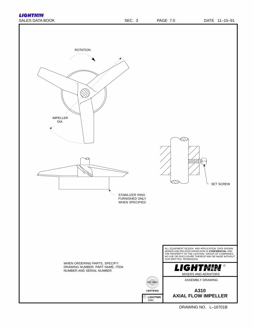
DRAWING NO. L–16701B
ROTATION
SET SCREW
STABILIZER RINGFURNISHED ONLYWHEN SPECIFIED
IMPELLERDIA.
WHEN ORDERING PARTS, SPECIFY:DRAWING NUMBER, PART NAME, ITEMNUMBER AND SERIAL NUMBER
LIGHTNIN1991
C
ISO 9001
CERTIFIED
SALES DATA BOOK SEC. 3 PAGE 7.0
A310AXIAL FLOW IMPELLER
ASSEMBLY DRAWING
MIXERS AND AERATORS
R

LIGHTNIN _____________________________________________________________________
REVISION DATE 12/28/05 LIGHTNIN INST. NO. IT-3839
P REVISED 01/05/06 MIXERS AND AERATORS LIGHTNIN 2005 PAGE 1 OF 1
FOR AN UP TO DATE REPRESENTATIVE LIST
PLEASE GO TO: www.lightnin-mixers.com
-OR-
CALL: 1-888-649-2378
1-888-MIX-BEST


Notes
REPAIR & SERVICE GUIDE
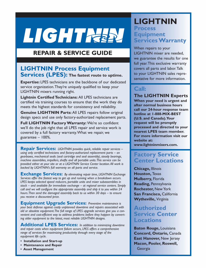
LIGHTNIN Process EquipmentServices (LPES): The fastest route to uptime.
Expertise: LPES technicians are the backbone of our dedicatedservice organization.They’re uniquely qualified to keep yourLIGHTNIN mixers running right.Lightnin Certified Technicians: All LPES technicians are certified via training courses to ensure that the work they domeets the highest standards for consistency and reliability.Genuine LIGHTNIN Parts: All LPES repairs follow originaldesign specs and use only factory-authorized replacement parts.Full LIGHTNIN Factory Warranty: We’re so confidentwe’ll do the job right that all LPES repair and service work iscovered by a full factory warranty.What we repair, we guarantee – 100%.
Repair Services: LIGHTNIN provides quick, reliable repair services –using only certified technicians and factory-authorized replacement parts – on gearboxes, mechanical seals (seal cartridge and seal assembly), steady bearings,machine assemblies, impellers, shafts and all portable units.This service can be provided either at your site or at a LIGHTNIN Service Center location. All work isbacked by LIGHTNIN’s full warranty on all parts and service.
Exchange Services: By eliminating repair time, LIGHTNIN ExchangeServices offer the fastest way to get up and running when a breakdown occurs.LPES keeps selected speed reducers, portable units and mixer subassemblies instock – and available for immediate exchange – at regional service centers. Simplycall and we will configure the appropriate assembly and ship it to you within 24hours.Then send the damaged assembly back to us within 30 days – to ensure you receive a discounted price.
Equipment Upgrade Services: Preventive maintenance isyour best defense against costly unplanned downtime and repairs associated withold or obsolete equipment.The full range of LPES upgrade services give you a con-venient and cost-efficient way to address problems before they happen by convert-ing older equipment to the latest, most reliable LIGHTNIN designs.
Additional LPES Services: In addition to minimizing downtimeand repair costs when equipment failure occurs, LPES offers a comprehensiverange of services for maximizing productivity through every stage of the equipment life cycle.• Installation and Start-up• Maintenance and Repair• Asset Management
LIGHTNINProcessEquipmentServices WarrantyWhen repairs to your LIGHTNIN mixer are needed,we guarantee the results for onefull year.This exclusive warrantycovers all parts and labor.Talk to your LIGHTNIN sales repre-sentative for more information.
Call:The LIGHTNIN ExpertsWhen your need is urgent andafter normal business hourscall our 24-hour response teamhotline at 1-888-MIX-BEST(U.S. and Canada).Yourrequest will be promptlyprocessed and directed to yournearest LPES team member.For more information visit ourwebsite at:www.lightninmixers.com.
Factory ServiceCenter LocationsChicago, IllinoisHouston, TexasMulberry, FloridaReading, PennsylvaniaRochester, New YorkSan Francisco, CaliforniaWytheville, Virginia
AuthorizedService CenterLocationsBaton Rouge, LouisianaConcord, Ontario, CanadaEast Hanover, New JerseyMacon, Pooler, Roswell,
Georgia