ministry of defence defence standard 00-101 · ministry of defence defence standard 00-101 issue 2...
TRANSCRIPT
Ministry of Defence Defence Standard 00-101 Issue 2 Publication Date 27 June 2008
Design Standards for Explosives Safety in MOD Ships and
Submarines
Part 3 Electrical Equipment and
Installation
Category 1
Reprinted 28 August 2008 to Incorporate Amendment 1
DEF STAN 00-101 Part 3 Issue 2
AMENDMENT RECORD
Amd No
Date Text Affected Signature and Date
1
20/08/08 Clause 1.9 re-written to latest legislation R Leary 20/08/08
Revision Note The previous magazine design standards have been protectively marked RESTRICTED, this standard is UNCLASSIFIED. Classified material associated with Response to ATTack on AMmunition (RATTAM) threat levels and mitigation techniques is published separately under classified Naval Authority Notice (NAN) EXP/03 in support of this standard. This document is available from DSS NAExp, it currently is protectively marked RESTRICTED.
Historical Record This standard supersedes the following:
Defence Standard 00-101 Part 3 Issue 1 Defence Standard 08-101 Part 3 Naval Engineering Standard 519
DEF STAN 00-101 Part 3 Issue 2
Unclassified 1
Preface Sponsorship
a. This Defence Standard (Def Stan) 00-101 is sponsored by the Directorate Sea Systems (DSS) Naval Authority Explosives (NAExp), Defence Equipment & Support (DE&S), Ministry of Defence (MOD).
b. The complete standard is titled: Design Standards for Explosives Safety in MOD Ships and Submarines, and comprises:
Part 1: Surface Ships Part 2: Submarines Part 3: Electrical Equipment and Installation Part 4: Generic Naval Environment Part 5: Ship Weapon Dynamic Safety
c. If it is found to be unsuitable for any particular requirement the MOD is to be informed in writing of the circumstances.
d. Any user of this Defence Standard either within MOD or in industry may propose an amendment to it. Proposals for amendments that are not directly applicable to a particular contract are to be made to the publishing authority identified on Page 1, and those directly applicable to a particular contract are to be dealt with using contract procedures.
e. No alteration is to be made to this Defence Standard except by the issue of an authorized amendment.
f. Unless otherwise stated, reference in this Defence Standard to approval, approved, authorised or similar terms, means the Ministry of Defence in writing.
g. Any significant amendments that may be made to this Defence Standard at a later date will be indicated by a vertical sideline. Deletions will be indicated by 000 appearing at the end of the line interval.
h. Extracts from British Standards within this Defence Standard have been included with the permission of the British Standards Institution.
Conditions of Release
i. This Defence Standard has been devised solely for the use of the MOD, and its contractors in the execution of contracts for the MOD. To the extent permitted by law, the Crown hereby excludes all liability whatsoever and howsoever arising (including but without limitation, liability resulting from negligence) for any loss or damage however caused when the Defence Standard is used for any other purpose.
j. This document is Crown Copyright and the information herein may be subject to Crown or third party rights. It is not to be released, reproduced or published without written permission of the MOD.
DEF STAN 00-101 Part 3 Issue 2
Unclassified
2
k. The Crown reserves the right to amend or modify the contents of this Defence Standard without consulting or informing any holder.
MOD Tender or Contract Process
l. This Defence Standard is the property of the Crown and unless otherwise authorised in writing by the MOD must be returned on completion of the contract or submission of the tender in connection with which it is issued.
m. When this Defence Standard is used in connection with a MOD tender or contract, the user is to ensure that he is in possession of the appropriate version of each document, including related documents, relevant to each particular tender or contract. Enquiries in this connection may be made of the Authority named in the tender or contract.
n. When Defence Standards are incorporated into contracts, users are responsible for their correct application and for complying with contractual and other statutory requirements. Compliance with a Defence Standard does not of itself confer immunity from legal obligations.
Categories of Defence Standard
o. The Category of this Defence Standard has been determined using the following criteria:
a) Category 1. If not applied may have a Critical affect on the following: Safety of the vessel, its complement or third parties. Operational performance of the vessel, its systems or equipment. b) Category 2. If not applied may have a Significant affect on the following: Safety of the vessel, its complement or third parties. Operational performance of the vessel, its systems or equipment. Through life costs and support. c) Category 3. If not applied may have a Minor affect on the following: MOD best practice and fleet commonality. Corporate experience and knowledge. Current support practice.
DEF STAN 00-101 Part 3 Issue 2
Unclassified 3
Related Documents
p. In the tender and procurement processes the related documents in each Section and Annex A can be obtained as follows:
i) British Standards British Standards Institution, 389 Chiswick High Road, London, W4 4AL ii) Defence Standards UK Defence Standardization, Kentigern House 65 Brown Street, Glasgow, G2 8EX iii) Other documents Tender or Contract Sponsor to advise.
q. All applications to Ministry Establishments for related documents are to quote the relevant MOD Invitation to Tender or Contract Number and date, together with the sponsoring Directorate and the Tender or Contract Sponsor.
r. Prime Contractors are responsible for supplying their subcontractors with relevant documentation, including specifications, standards and drawings.
Health and Safety
Warning
s. This Defence Standard may call for the use of processes, substances and procedures that may be injurious to health if adequate precautions are not taken. It refers only too technical suitability and in no way absolves either the supplier or any user from statutory obligations relating to health and safety at any stage of manufacture or use. Where attention is drawn to hazards, those quoted may not necessarily be exhaustive.
t. This Defence Standard has been written and is to be used taking into account the policy stipulated in Joint Service Publication (JSP) 430: MOD Ship Safety Management System Handbook.
Additional Information
u. This standard provides mandatory Performance Requirements for the design, construction and ship fitting of MOD ships in respect of explosives safety issues arising from stowage, handling and use of explosives onboard. The Performance Requirements are supplemented by Approved Codes of Practice (ACOP) and Guidance, which provide design best practice and corporate knowledge and experience.
DEF STAN 00-101 Part 3 Issue 2
Unclassified
4
v. This standard has been produced by DSS Naval Authority Explosives, Defence Equipment & Support Agency, Ministry of Defence. The Point of Contact for matters pertaining to the technical content of the standard is DSS NAExp, Ash 3c, #3311, MOD Abbey Wood, BRISTOL BS34 8JH.
w. This standard has been agreed by the authorities concerned with its use and is intended to be used whenever relevant in all future designs, contracts etc. and whenever practicable by amendment to those already in existence. If any difficulty arises which prevents application of the Standard, the sponsor shall be informed so that a remedy may be sought.
x. Any enquiries regarding this standard in relation to an invitation to tender or a contract in which it is incorporated are to be addressed to the responsible Platform Duty Holder (PDH), normally the Platform Integrated Project Team (PIPT), named in the invitation to tender or contract.
y. Compliance with this Standard shall not in itself relieve any person from any legal obligations imposed upon them.
z. This standard has been devised solely for the use of the MOD and its contractors in the execution of contracts for the MOD. To the extent permitted by law, the MOD hereby excludes all liability whatsoever and howsoever arising (including, but without limitation, liability resulting from negligence) for any loss or damage however caused when the standard is used for any other purpose.
aa. The mandatory requirements and associated guidance in this Standard are intended to meet the policy of the Secretary of State for Defence to put in place regulations that are at least as good as civil requirements, so far as is reasonably practicable, where MOD has exemption from civil legislation. Use of this Standard in maritime platform acquisition programmes is also intended to contribute towards optimisation of capability.
DEF STAN 00-101 Part 3 Issue 2
Unclassified 5
CONTENTS 0. INTRODUCTION ............................................................................................................................ 8
1. SCOPE ............................................................................................................................................. 9
2. WARNING...................................................................................................................................... 10
3. RELATED DOCUMENTS............................................................................................................ 11
4. DEFINITIONS AND ABBREVIATIONS..................................................................................... 11
5. AMENDMENT ............................................................................................................................... 12
6. SPONSORSHIP OF THE REQUIREMENT AND SECURITY .............................................. 12
7. STATUTORY LEGISLATION AND MOD REGULATION FOR PLATFORM EXPLOSIVE SAFETY ....................................................................................................... 13
8. INTRODUCTION TO PLATFORM EXPLOSIVES SAFETY AND CERTIFICATION ...................................................................................................................................... 14
9. DESIGN FOR PLATFORM EXPLOSIVES SAFETY INCORPORATING THREAT HAZARD ASSESSMENT & LINES OF DEFENCE............................................................ 16
APPENDIX 1 DESIGN REQUIREMENTS FOR ELECTRICAL EQUIPMENT IN MAGAZINES, WSCs AND DESIGNATED DANGER AREAS .......................................................... 17 1.1 Description ..................................................................................................................................... 17 1.2 Performance Requirements – Categorisation of Magazines ................................................. 18 1.3 Performance Requirements – Basic Principles for Magazine Electrical Equipment.................................................................................................................................................. 18 1.4 Performance Requirements - Basic Principles – Zone 2 Magazines ................................... 18 1.5 ACOP - Basic Principales – Zone 2 Magazines ...................................................................... 19 1.6 ACOP – Zone 2 Magazine Electrical Equipment Categories ................................................ 19 1.7 Performance Requirement – Assessment of Equipment for use in Zone 2 ........................ 21 1.8 ACOP – Electrical Equipment Enclosures................................................................................ 21 1.9 ACOP – The Radio Frequency (rf) Environment ..................................................................... 22 1.10 ACOP – Magnetic Environment and Degaussing Cables...................................................... 22 1.11 Guidance - Basic Principles for Magazine, WSC & DDA Electrical Equipment.................................................................................................................................................. 23 1.12 Guidance - Basic Principles for Zone 2 Magazine, WSC & DDA Electrical Equipment.................................................................................................................................................. 23 1.13 Guidance on Maximum Surface Temperature ......................................................................... 26 1.14 Guidance on Electrical Equipment Enclosures........................................................................ 27 1.15 Guidance on Intrinsically Safe Equipment................................................................................ 28 1.16 Guidance on Mobile Mechanical Handling Equipment (MMHE).......................................... 28 1.17 Guidance on Mechanical Hazards ............................................................................................. 29 1.18 Guidance on Safety and Environmental Management Systems (SEMS) ........................... 29
APPENDIX 2 DESIGN REQUIREMENTS FOR ELECTRICAL INSTALLATIONS ........................ 31 2.1 Description ..................................................................................................................................... 31 2.2 Performance Requirements for General Installation and Siting............................................ 31 2.3 Performance Requirements for Cabling.................................................................................... 32
DEF STAN 00-101 Part 3 Issue 2
Unclassified
6
2.4 Performance Requirements for Circuit Isolation...................................................................... 33 2.5 Performance Requirements for Emergency Supplies ............................................................ 34 2.6 Performance Requirements for Fixed Lighting ........................................................................ 34 2.7 Performance Requirements for Power Output Connectors ................................................... 35 2.8 Performance Requirements for Installed Test Equipment ..................................................... 35 2.9 Performance Requirements for Electrically Controlled Handling Machinery ...................... 36 2.10 Performance Requirements for Safety-Related Devices ....................................................... 36 2.11 Performance Requirements for Earthing .................................................................................. 36 2.12 ACOP for Siting of Equipment .................................................................................................... 37 2.13 ACOP for Cabling ......................................................................................................................... 37 2.14 ACOP for Circuit Isolation ........................................................................................................... 37 2.15 ACOP for Emergency Supplies .................................................................................................. 38 2.16 ACOP for Luminaries (Fixed Lighting) ...................................................................................... 38 2.17 ACOP for Power Output Connectors......................................................................................... 39 2.18 ACOP for Test Equipment........................................................................................................... 39 2.19 ACOP for Electrically Controlled Handling Machinery............................................................ 39 2.20 ACOP for Safety-Related Devices ............................................................................................. 39 2.21 ACOP for Earthing........................................................................................................................ 39 2.22 Guidance on General Electrical Installation ............................................................................. 40 2.23 Guidance on Siting of Equipment .............................................................................................. 40 2.24 Guidance on Cabling.................................................................................................................... 41 2.25 Guidance on Circuit Isolation...................................................................................................... 43 2.26 Guidance on Fixed Lighting ........................................................................................................ 43 2.27 Guidance on Power Output Connectors ................................................................................... 44 2.28 Guidance on Test Equipment ..................................................................................................... 44 2.29 Guidance on Electrically Controlled Handling Machinery ...................................................... 44
APPENDIX 3 DESIGN REQUIREMENTS FOR ADJACENT COMPARTMENTS......................... 46 3.1 Description ..................................................................................................................................... 46 3.2 Performance Requirements for Electrical Design in Adjacent Compartments........................................................................................................................................... 46 3.3 Performance Requirements for Electrical Equipment in Adjacent Compartments........................................................................................................................................... 46 3.4 Performance Requirements for Electrical Installation in Adjacent Compartments........................................................................................................................................... 46 3.5 Performance Requirements for Smoke/Heat Detection Equipment in Adjacent Compartments .......................................................................................................................... 47 3.6 ACOP for Special Requirements in Adjacent Compartments ............................................... 47 3.7 ACOP for Special Requirements for Installation in Adjacent Compartments........................................................................................................................................... 47 3.8 ACOP for Smoke and Heat Detection Equipment................................................................... 48 3.9 Guidance on Electrical Equipment in Adjacent Compartments ............................................ 48
APPENDIX 4 DESIGN REQUIREMENTS FOR TEMPORARILY INSTALLED EQUIPMENT ............................................................................................................................................. 49 4.1 Description ..................................................................................................................................... 49 4.2 Performance Requirements for Portable Equipment .............................................................. 49 4.3 Performance Requirements for Emergency Lighting.............................................................. 49 4.4 ACOP for Temporarily Installed Equipment ............................................................................. 49
DEF STAN 00-101 Part 3 Issue 2
Unclassified 7
4.5 Guidance on Temporarily Installed Equipment........................................................................ 50 4.6 Guidance on Compliance for Portable Equipment .................................................................. 50
APPENDIX 5 ELECTROMAGNETIC INDUCTION, RADIO FREQUENCY AND ELECTROSTATIC HAZARDS................................................................................................................ 52 5.1 Description ..................................................................................................................................... 52 5.2 Performance Requirements for Design to Reduce Electromagnetic Induction, Radio Frequency and Electrostatic Hazards ..................................................................... 52 5.3 ACOP for Electromagnetic Induction, Radiation and Electrostatic Hazards ....................... 53 5.4 Guidance on Electromagnetic Induction, Radiation and Electrostatic Hazards ...................................................................................................................................................... 53
APPENDIX 6 POTENTIALLY HAZARDOUS ENVIRONMENTS OF A SPECIAL NATURE .................................................................................................................................................... 55 6.1 Description ..................................................................................................................................... 55 6.2 Performance Requirements for Potentially Hazardous Environments of a Special Nature........................................................................................................................................... 55 6.3 Performance Requirements for Degaussing Cables .............................................................. 55 6.4 Performance Requirements for Waveguides ........................................................................... 55 6.5 Performance Requirements for Cranes .................................................................................... 55 6.6 Performance Requirements for Ship to Shore Electrical Connections ................................ 55 6.7 ACOP for Waveguides................................................................................................................. 55 6.8 ACOP for Cranes.......................................................................................................................... 56 6.9 ACOP for Ship to Shore Electrical Connections...................................................................... 56 6.10 ACOP for Earthing of Weapon Containers ............................................................................... 56 6.11 Guidance on Degaussing Cables .............................................................................................. 56 6.12 Guidance on Waveguides ........................................................................................................... 56 6.13 Guidance on Ship to Shore Connections ................................................................................. 57
APPENDIX 7 Electrical Requirements for ISO Containers................................................................ 58 7.1 Description ..................................................................................................................................... 58 7.2 ACOP for Earthing of ISO Containers ....................................................................................... 58 7.3 Guidance on Earthing of ISO Containers ................................................................................. 58
ANNEX A - RELATED DOCUMENTS .................................................................................................. 59
ANNEX B - ABBREVIATIONS................................................................................................................ 62
ANNEX C - DEFINITIONS ...................................................................................................................... 65
DEFSTAN 00-101 Part 3 Issue 2
Unclassified 8
DESIGN STANDARDS FOR EXPLOSIVES SAFETY IN MOD SHIPS
AND SUBMARINES - STANDARDS FOR DEFENCE – PART 3: ELECTRICAL EQUIPMENT AND INSTALLATION
0. INTRODUCTION
0.1. This standard is authorised by the Naval Authority (Explosives) by delegated authority from Controller of the Navy and Chairman of the Ship Safety Board on behalf of the MOD Ship Safety Board, and its use is a mandatory requirement of JSP 430 Part 3, Naval Authority Regulations (NAR) Chapter 8 (Explosives).
0.2. The aim of this Standard is to provide requirements and guidance to assist in providing an acceptably safe integration of Ordnance, Munitions Explosives (OME) into MOD ships.
0.3. This Standard has been issued to identify the mandatory Performance Requirements for the design, construction and ship fitting of all JSP 430 applied ships in respect to safety issues arising from stowage, handling and use of explosives. It incorporates the best practice contained in previous magazine standards Naval Engineering Standard (NES) 519, NES 593 and Def Stan 08-101 but is written to both support the risk based Safety Management System (SMS) introduced by JSP 430 Pt 3 Chapter 8 (Naval Authority Regulations) and allow prescriptive design features to continue under specified Approved Codes of Practice or Guidance.
0.4. Discrete sections cover specific topics providing Descriptions, Performance Requirements, Approved Codes of Practice (ACOP) and Guidance for each. This Standard is a component of the Safety Management System process mandated by Naval Authority Regulations Chapter 8 (Explosives) (NAR Ch 8) which defines how Ordnance Munitions and Explosives (OME) should be integrated and used safely in ships. It is essential that Def Stan 00-101 is read in conjunction with Naval Authority Regulations Chapter 8 (Explosives). In addition, Maritime Acquisition Publication (MAP) 01-103, Ship Explosives Safety Case (SESC) – Guidance For Platform Duty Holders, Part 1 provides further guidance on the process for developing an SESC.
0.5. This Standard is to be specified in the User Requirements Documentation and System Requirements for all MOD Ships that embark munitions. Def Stan 00-101 is authorised by the Naval Authority Explosives and its use is a mandatory requirement of the Naval Authority Regulations, Chapter 8 (Explosives).
0.6. The user of this standard is directed to ANNEX C that should be read early in the use of this standard to ensure that the terminology is understood and to avoid misinterpretation.
DEFSTAN 00-101 Part 3 Issue 2
Unclassified 9
1. SCOPE
1.1. The MOD Ships to which this standard applies are defined in JSP 430 and JSP 430 Part 3 Naval Authority Regulations, Chapter 8 (Explosives). These include HM Ships and Submarines, Royal Fleet Auxiliaries (RFA), Marine Services, other ships owned by MOD, Government Owned Contractor Operated (GOCO) vessels (where these are owned by MOD), and ships on MOD charter. The term “ship” is intended to include vessels, launches, tenders, lighters and any other craft carrying any explosives. The Naval Authority may determine that a specific platform is not required to comply where no hazard exists but does not issue exemption certificates. All such maritime platforms are described as MOD Ships in the remainder of this document.
1.2. This Standard applies to the design, construction and ship fitting of all MOD Ships built to MOD or Classification Society constructional standards and operated by the Royal Navy, Army, Royal Air Force, RFA or Marine Services. The standard also applies to Marine Services vessels supplied as Government Furnished Equipment for contract operations and MOD authorised modifications undertaken to charter vessels.
1.3. It is to be applied to contracts that specify requirements that have any effect upon the explosives safety of the platform. This will include the magazines, adjacent compartments and ammunition routes and handling equipment within MOD ships in which explosives will be embarked, moved, stowed and used. It is also to be applied to all Refits and Repair work affecting any of these including Alterations and Additions and Modifications. It may also include other design issues throughout the platform that impact on explosives safety.
1.4. The complete standard is titled: Design Standards for Explosives Safety in MOD Ships and Submarines, and comprises:
Part 1 – Surface Ships
Part 2 – Submarines
Part 3 – Electrical Equipment and Installation
Part 4 – Generic Naval Environment
Part 5 - Ship Weapon Dynamic Safety
1.5. Classified material associated with RATTAM threat levels and mitigation techniques is published separately under classified NAN EXP/03 in support of this standard. This document is available from DSS NAExp; it is currently protectively marked RESTRICTED.
DEFSTAN 00-101 Part 3 Issue 2
Unclassified 10
1.6. This standard has been written primarily to support the risk based shipborne explosives Safety Management System (SMS) introduced by NAR JSP 430 Part 3 Chapter 8 Explosives. Where legacy vessels have been certificated under previous transition procedures, it is not necessary to implement additional work to meet this standard, unless major modifications are undertaken to a magazine or weapon system. In that case, this Defence Standard must be implemented.
1.7. Supplementary information, information requiring a higher protective marking and temporary instructions will be issued in the form of Naval Authority Notices (NAN). NANs relating to explosives safety in MOD ships and submarines are available from Naval Authority System Library website (www.nakmo.co.uk) or the Sponsor of this Standard.
1.8. For the storing and handling of petroleum, oils, lubricants (POL) and certain other hazardous stores in HM Ships, BR1754 is to be consulted (Navy Service Authority: Systems Fuels & Lubricants, WSA, MPS216, Abbey Wood , Bristol).
1.9. Regulations governing the safe stowage and handling of explosives in Magazines in RFAs are covered in JSP 862 Chapter 13. Regulations covering the safe stowage and handling of explosives in Charter shipping are included in the IMDG Regulations.
2. WARNING
2.1. The Ministry of Defence (MOD), like its contractors, is subject to both United Kingdom and European laws regarding Health and Safety at Work. All MoD Standards either directly or indirectly invoke the use of processes and procedures that could be injurious to health if adequate precautions are not taken. MoD Standards or their use in no way absolves users from complying with statutory and legal requirements relating to Health and Safety at Work.
2.2. This is a mandatory Category 1 Standard. If not applied it may have a Critical affect on the following:
a) Safety of the ship, its complement or third parties.
b) Operational performance of the ship, its systems or equipment.
c) Through life costs and support.
2.3. If the Platform Duty Holder (PDH) proposes not to apply this mandatory Category 1 Standard, agreement must be obtained from Naval Authority Explosives and the relevant Director of Equipment Capability (DEC). Details of any such agreement are to be formally recorded in the Safety Case. In the event of a MOD enquiry or any prosecution under Health and Safety legislation, if it is proved that the relevant requirements were not followed, the PDH will need to show that he has complied with the Naval Authority Regulations in some other way or an enquiry or court may find him at fault.
DEFSTAN 00-101 Part 3 Issue 2
Unclassified 11
2.4. In this standard, Performance Requirements are mandatory (Category 1) requirements. Additionally clauses including the words “shall”, “must”, “is to”, “are to” also are mandatory.
2.5. This standard contains Approved Code of Practice (ACOP), which has been approved by the Naval Authority (Explosives) as good practice. It gives practical advice that may be used to assist in complying with this standard. Alternative methods to those set out in the ACOP may be used providing they are justified in the safety case.
2.6. This standard also contains other, more general Guidance. This guidance reflects corporate knowledge and experience and is issued by the Naval Authority Explosives to assist duty holders’ understanding of the subject area. It may not be exhaustive and all users are recommended to contact DSS NAExp for the latest information.
3. RELATED DOCUMENTS
3.1. The publications listed in Annex A are referred to in the text of this standard.
3.2. Reference in this standard to any related document means that in any invitation to tender or contract the edition and all amendments current at the date of such tender or contract apply unless a specific edition is indicated.
3.3. In consideration of 3.2 above, users shall be fully aware of the issue and amendment status of all related documents, particularly when forming part of an invitation to tender or contract. Responsibility for the correct application of standards rests with users.
3.4. The Directorate of Standardisation (DStan) can advise where related documents are obtained. Requests for such information can be made to the DStan Helpdesk.
4. DEFINITIONS AND ABBREVIATIONS
4.1. For the purpose of this standard the abbreviations and definitions listed in Annex B and Annex C apply. The user of this standard is directed to Annex C that should be read early in the use of this standard to ensure that the terminology is understood and to avoid misinterpretation.
DEFSTAN 00-101 Part 3 Issue 2
Unclassified 12
5. AMENDMENT
5.1. If this Standard is found to be unsuitable for any particular requirement, the sponsor is to be informed in writing with a copy to DSS NAExp, Ash 3c #3311, MOD Abbey Wood, BRISTOL BS34 8JH.
5.2. Any user of this Standard either within MOD or in industry may propose an amendment to it. Proposals for amendments that are not directly applicable to a particular contract are to be made to the MOD and those directly applicable to a particular contract are to be dealt with using existing procedures or as specified in the contract.
5.3. No alteration is to be made to this Standard except by the issue of an authorised amendment. Amendments, supplementary information and temporary instructions will be issued in the form of Naval Authority Notices (NAN) by DSS NAExp.
5.4. Unless otherwise stated, reference in this Standard to approval, approved, authorised or similar terms, means by the Ministry of Defence in writing.
6. SPONSORSHIP OF THE REQUIREMENT AND SECURITY
6.1. JSP 430 introduces the concept of Key Hazard Safety Management by MOD Platform Duty Holders (PDH) who are normally the associated Platform Integrated Project Team Leaders (PIPTL). JSP 430 defines a Key Hazard to represent a significant danger to the lives of several persons and whose consequence may cause the loss of the ship or significant damage to the environment. JSP 430 mandates the Regulation of these key hazards by an independent assurance body and for explosives the Naval Authority Explosives (NAExp) in DSS undertakes this role, with delegated authority from the Ships Safety Board. DSS NAExp sponsors this Category 1 mandatory Standard. It is approved by the Naval Authority Explosives Advisory Committee (NAEAC).
6.2. Throughout this document the following convention is used when referring to the Regulatory body or its incumbents. NAExp relates generically to Naval Authority Explosives and its policies, DSS NAExp relates to the Secretariat.
6.3. NAExp has published a suite of documents relating to the use of this Standard, that comprise JSP Part 3, Naval Authority Regulations Chapter 8 – Explosives, JSP 862 – MoD Maritime Explosives Regulations (Operator Requirements) and Maritime Acquisition Publication (MAP) 01-103, Ship Explosives Safety Case (SESC) – Guidance For Platform Duty Holders, Part 1. They will be referenced in the Acquisition Management System (AMS) and are available via the Naval Authority System Library website at www.nakmo.co.uk.
DEFSTAN 00-101 Part 3 Issue 2
Unclassified 13
7. STATUTORY LEGISLATION AND MOD REGULATION FOR PLATFORM EXPLOSIVE SAFETY
7.1. Refer to this Defence Standard Part 1 or Part 2, Section 7, for the information relating to this subject matter.
DEFSTAN 00-101 Part 3 Issue 2
Unclassified 14
8. INTRODUCTION TO PLATFORM EXPLOSIVES SAFETY AND CERTIFICATION
Background 8.1. Platform explosives safety has historically been achieved by following prescriptive rules and standards set by the Naval Magazine Safety Committee (NMSC), now Naval Authority Explosives (NAExp). Safety efforts were targeted at preventing explosives initiation, as it was accepted that there was little that could be done to manage the consequences of an explosive event.
8.2. MOD inclusion in the Health and Safety at Work Etc. (HSAW) Act 1974 and the Secretary of State’s statement led to the publication in 1996 of JSP 430 for MOD Ship Safety Management. This introduced the requirement for safety cases within which there would be independent regulation of Key Hazards by MOD Naval Authorities. Safety Cases are generally risk based but JSP 430 part 2, issue 3 states “…however prescription can still be useful in certain contexts.” Platform Explosives Safety Management Drivers 8.3. In line with civil statutory authorities the MOD recognised that the fully prescriptive regimes within which explosives hazards were regulated was inappropriate and a change to risk based regulation was made.
8.4. This risk-based approach requires an explosives safety case to be produced which demonstrates that the risks posed by explosives on a platform are acceptable. The major aspects of the safety risk that must be considered are:
a. Operational Loss of Platform b. Crew Risk c. Societal Risk d. Environmental Risk
8.5. Explosives embarked onboard ship clearly present hazards to the safety of the ship, personnel and the environment. To meet the safety requirements of JSP 430 these hazards must have their risks reduced to levels that are tolerable and ALARP. This means all measures necessary should be adopted to reduce the risk of an incident unless the cost of doing so (in money, time or trouble) is shown to be grossly disproportionate to the reduction in risk achieved (further information is presented in JSP 430). The management of explosives safety onboard JSP 430 applied platforms is described in JSP 430 Part 3, Chapter 8. The intrinsic safety of the OME is defined by the requirements of JSP 520.
DEFSTAN 00-101 Part 3 Issue 2
Unclassified 15
Platform Explosives Safety Management Process 8.6. The foundation of the platform explosives safety management process within MOD, for the maritime environment, is the requirement for a Certificate of Safety Explosives (CSE) to be in place before embarking, handling, stowing and using explosives onboard JSP 430 applied platforms.
8.7. The existence of a CSE provides assurance that, for the named platform, the PDH has demonstrated through a safety case that hazards from explosives approved for embarkation, are tolerable and ALARP.
8.8. Platform explosives safety is achieved through a coherent partnership between design, material state and operator procedures. The PDH is responsible for achieving this coherence and demonstrating it through a risk based safety case, in accordance with JSP 430. However, the safe integration of explosives into a maritime platform can only be achieved after the intrinsic explosives safety performance and characteristics of the OME have been established through the JSP 520 process.
8.9. Full details of the process for obtaining a Certificate of Safety Explosives are contained within JSP 430 Part 3 Chapter 8.
DEFSTAN 00-101 Part 3 Issue 2
Unclassified 16
9. DESIGN FOR PLATFORM EXPLOSIVES SAFETY INCORPORATING THREAT HAZARD ASSESSMENT & LINES OF DEFENCE
9.1. The design of the platform is vital to ensuring that the risks from explosives are Tolerable and ALARP. This Defence Standard provides Performance Requirements, Approved Codes of Practice and Guidance for the stowage and handling of explosives. Guidance for explosive safety management and assessment is provided in Maritime Acquisition Publication (MAP) 01-103, Ship Explosives Safety Case (SESC) – Guidance For Platform Duty Holders, Part 1, Edition 1 supporting NAR Chapter 8 by providing fully detailed guidance on practices and methodologies that have been used previously to good effect and how they should be used during the development of a ship explosives safety case. This includes topics such as:
a. SESC Interfaces, Scope and Planning b. Regulatory Standards and Tolerability Principles c. Threat Hazard Assessment (THA) d. Lines of Defence (LOD) e. Dynamic Safety
DEFSTAN 00-101 Part 3 Issue 2
Unclassified 17
APPENDIX 1 DESIGN REQUIREMENTS FOR ELECTRICAL EQUIPMENT IN MAGAZINES, WSCs AND DESIGNATED DANGER AREAS
1.1 Description
1.1.1 This Appendix sets out the Performance Requirements, ACOP and Guidance that relate to the key design requirements for electrical equipment fitted in magazines, Weapon Stowage Compartments (WSC) and Designated Danger Areas (DDA).
1.1.2 Ships are subject to a range of scenarios and environments that could produce threats. If any of these are allowed to have an impact on susceptible munitions or explosive stores carried onboard the reaction may lead to unacceptable consequences to operational capability, to the platform, to service personnel, to civilians, to the environment and to any adjacent facility.
1.1.3 The Performance Requirements, ACOP and Guidance below are intended to support duty holders in achieving an optimised design that reduces the potential consequences to the platform from threats to at least Tolerable and ALARP (as low as reasonably practicable). Guidance is also provided to enable an optimised design for electrical equipment in the magazines and associated areas within a ship or submarine, which integrates the munitions into the platform and addresses the hazards produced from the threats.
1.1.4 The Performance Requirements cited in this standard cover all of the components of an electrical system installed within a magazine, WSC or DDA such as rotating electrical machines, ventilation systems, switchgear, fuses, plugs and sockets, luminaries, sensors/detectors or any other devices that either consume, transmit or generate electrical energy. It also includes any mobile equipment (e.g. Mechanical Handling Equipment, Test Equipment, Computers, etc.) that are taken into the Magazine, WSC or DDA.
1.1.5 One of the most significant explosive safety risks relates to the ignition of a flammable atmosphere in a magazine. Most modern munitions are not capable of producing an explosive atmosphere since they do not contain a flammable liquid or gel fuel. However, some magazines are fitted with hydraulic systems, often for the handling of the munitions that contain flammable hydraulic fluids. Therefore, due to the risk of an explosive atmosphere developing, those magazines for munitions that contain a flammable liquid or gel fuel and/or a system containing a flammable hydraulic fluid should be designed to minimise this risk.
1.1.6 To enable the appropriate application of the Performance Requirements, ACOPs and Guidance, Magazines’ Weapon Stowage Compartments (WSCs) and Designated Dangerous Areas (DDAs) are categorised as either Zone 2 or Non Zone 2. This categorisation shall be performed as a mandatory Performance Requirement in accordance with Section 1.2 of this Appendix.
DEFSTAN 00-101 Part 3 Issue 2
Unclassified 18
1.1.7 For simplicity the magazines will be referred to in this standard as either: a) Zone 2 Magazine, or b) Magazine (Non Zone 2 Magazines). 1.1.8 The Performance Requirements, ACOP and Guidance associated with other non Explosive Atmosphere specific electrical safety topics are covered in subsequent Appendices.
1.1.9 The main features of the electrical design shall be summarised in the Ship Explosives Safety Case (SESC). Guidance on appropriate design is given below and in this standard.
1.2 Performance Requirements – Categorisation of Magazines
1.2.1 Each Magazine, WSC or DDA shall be categorised as being either a Zone 2 Magazine or a Non Zone 2 Magazine.
1.2.2 The ATEX Directive (EU 94/9/EC), which was introduced in the United Kingdom by the Dangerous Substances and Explosives Atmospheres Regulations (DSEAR) (Statutory Instrument 2002 No. 2776), requires that where an explosive or flammable atmosphere may be present, only electrical equipment that will not provide an ignition source is to be used.
1.2.3 BS EN 60079-10:2003 shall be used to assess the categorisation of hazardous atmospheres in all Magazines, WSCs and DDAs.
1.3 Performance Requirements – Basic Principles for Magazine Electrical Equipment
1.3.1 All electrical equipment or equipment containing electrical components that is used in a magazine (either permanently fixed or portable) shall be essential to the function of the magazine.
1.3.2 Where necessary, electrical equipment shall be protected from the effects of the activation of the spray system to minimise the risk of fire and / or to ensure that the equipment continues to function after activation of the magazine spray system.
1.3.3 Magazine, WSC, DDA and adjacent compartment electrical designs must also meet the requirements of other Safety and Environmental Management Systems (SEMS) and Key Hazard requirements as appropriate. The duty holder shall take measures to ensure all relevant requirements are satisfied.
1.4 Performance Requirements - Basic Principles – Zone 2 Magazines
1.4.1 In additional to the general magazine performance requirements detailed in this appendix at 1.3, Zone 2 Magazines shall also meet the following requirements:
DEFSTAN 00-101 Part 3 Issue 2
Unclassified 19
1.4.2 Where magazine spaces are designated as Zone 2, the design requirements for equipment and its installation shall be based upon an assessment of the gas atmospheres (both potential constituents and occurrence) likely to be encountered.
1.5 ACOP - Basic Principales – Zone 2 Magazines
1.5.1 The United Nations Hazard Classification Code (HCC) uses the Compatibility Group J to identify weapons that contain a flammable liquid fuel or gel, e.g. 1.1J. Further information on the United Nations Hazard Classification Codes and Compatibility Group can be found in JSP862, Vol. 1 Chapter 5.
1.5.2 The risk of an inadvertent explosion within a Magazine, WSC or DDA containing HCC J munitions or a system containing a flammable hydraulic fluid can be reduced significantly by measures that prevent concentrations of flammable gases from occurring or forming and/or which eliminate or minimise sources of ignition. This Defence Standard largely addresses the latter set of measures based on the series of IEC and BS EN 60079 and 50014 standards that cover the requirements for electrical apparatus (equipment) to be installed in spaces in which explosive atmospheres may be encountered. This approach is analogous to the concepts of the European ATEX (Atmosphères Explosibles) Directives and the relevant enabling UK legislation – the Dangerous Substances and Explosives Atmospheres Regulations. A full explanation of the relevant legislation is given in Section 7.
1.5.3 Explosive atmospheres are not present under normal conditions in a ship’s magazine, even if it contains HCC J explosive stores or a hydraulic system with a flammable fluid. However, the potential hazard of vapour evolution could still occur under a variety of fault or credible accident or action damage conditions. HCC J magazines, submarine WSCs and DDAs (and those containing flammable hydraulic fluid) may be classified as Zone 2 Areas according to BS EN 60079-10. This is directly equivalent to the ATEX equipment Group II Category 3 condition. The classification is to be justified in the SESC.
1.6 ACOP – Zone 2 Magazine Electrical Equipment Categories
1.6.1 Sources of ignition should be eliminated whenever possible. It may be more realistic to design electrical equipment to confine its sources of energy or to function acceptably below the ignition temperature or spark/arc ignite energies for a given gas atmosphere.
1.6.2 BS EN 60079-14 and its guide PD 60079-14 state that electrical equipment for use in Zone 2 areas can be:
a) That designed for Zone 0 or Zone 1. Zone 0 describes an area in which a gas atmosphere is present continuously or for long periods. The equipment must be in accordance with the intrinsic safety standard designated ‘is’ given in IEC 60079-11 or EN 50020. Zone 1 describes an area in which a gas atmosphere is likely to be present during normal operation. The equipment must be in accordance with one of a variety of standards (IEC 60079-1, -2, -5, -7, -11 or –18). Electrical equipment of protection flameproof (designated ‘d’) IEC 60079-1 and intrinsic (designated ‘i’) IEC
DEFSTAN 00-101 Part 3 Issue 2
Unclassified 20
60079-11 are Group II but are further subdivided into IIA, IIB and IIC, which are related to gas/vapour subdivisions given in IEC 60079-0 Annex A. The subdivisions relate to the ignition of gases by energy discharge between conductors arranged in increasing degrees of ignitability. Group C contains only hydrogen, acetylene and carbon disulphide. The data upon which these tables are derived is given in IEC 60079-20. Selection of such equipment could be an expensive option unless the equipment is in volume production for any purpose.
b) Electrical equipment specifically designed for Zone 2, such as that designed to Protection Type ‘n’, is given in IEC 60079-15 or BS EN 50021. Such equipment is not capable of igniting a surrounding gas atmosphere in normal operation. If the apparatus contains enclosed break devices, non-incendive components or uses energy limitation, then the equipment selected has to follow the same sub-divisions as for (a) above relating to the degree of ignitability.
c) Electrical equipment which does not have ignition capable hot surfaces in normal operation and either does not produce sparks or arcs nor has sparks or arcs that will ignite the gas atmosphere but has electrical parameters in accordance with IEC 60079-11. Such equipment is assessed according to IEC 60079-15. The guide to the application of BS EN 60079-14 provides good advice on the protective measures to be employed.
1.6.3 A maximum surface temperature of 135 degrees C for surface ships will cover most main magazines likely to contain volatile explosive compositions such as solid and liquid propellants. On occasion, a lower temperature may be needed. This is to be justified in the SESC.
1.6.4 A maximum surface temperature of 100 degrees C is set for equipment in submarines. This is based on the fact that liquid propellants are currently used in munitions deployed in submarines. The electrical equipment in submarine is therefore likely to be classified as IIB as justified in the SESC.
1.6.5 In the concept stage of ship design, where the characteristics of the munitions to be stowed within a magazine may not be known, the electrical equipment ‘Grading’ to IEC 60079 shown in Table 1 below is recommended as a default design standard:
Table 1 — Electrical Equipment Grading
Grading Surface Ships Submarines Maximum equipment surface temperature
135°C 100°C
Classification T4 T5 Apparatus Group IIB IIB
DEFSTAN 00-101 Part 3 Issue 2
Unclassified 21
1.7 Performance Requirement – Assessment of Equipment for use in Zone 2 Atmospheres.
1.7.1 The assessment for each Zone 2 Magazine, WSC or DDA relating to the potential hazard of gas evolution based on the explosive material to be stowed shall be recorded in the SESC. Electrical equipment categories (i.e. IIA, IIB or IIC) shall be allocated according to the result of each assessment.
1.7.2 Equipment that has been designed for use in Zones 0 or 1 (see Appendix A.12.3) shall be certified by an independent third party. Prior to 1996 this was undertaken by bodies such as the Electrical Equipment Certification Service (EECS). Since 1996, the ATEX Notified Bodies have undertaken these functions. The ATEX conformity assessment procedure options vary according to the ATEX Group and Category of equipment – see Guidance. Either European Community (EC) type examination, with production quality assurance, or product verification, or conformity to type, or unit verification, or internal control of production will be required. A copy of the certificate/EC declaration of conformity (see Guidance) is to be obtained if such equipment is to be used in magazines, WSCs or DDAs. Documentation must be available covering the watertightness of the enclosure if this is also required.
1.7.3 NOTE: Certificates of Compliance were declared invalid by the Equipment and Protective Systems Intended for Use in Potentially Explosive Atmospheres Regulations 1996. Older Certificates of Compliance may use the obsolete British Approvals Service for Electrical Equipment in Flammable Atmospheres (BASEEFA) name. Such certificates should now be supported by an EC declaration of conformity. For declarations of conformity issued in a foreign language it is mandatory to obtain authenticated copies of the original declaration in the English language.
1.7.4 NOTE: Safety Cases for electrical equipments fitted prior to 2003 in current In-Service ship classes may continue to rely on the Certificate of Compliance documentation as proof of compliance with IEC requirements.
1.7.5 The assessments and results from electromagnetic compatibility and electrostatic protection studies and tests (see Appendix A.12) at the equipment level shall be recorded in the SESC.
1.8 ACOP – Electrical Equipment Enclosures
1.8.1 Where CO2 injection sockets (NSN 4210-99-529-3637) are fitted in accordance with Def Stan 08-107/NES 501, the socket will need to be sealed effectively (e.g. by a foil disk) to prevent ingress of dirt. The seal should be capable of being easily broken or breached by the insertion of the injector. Design of the socket or a guard should prevent inadvertent breakage. The foil seal (NSN 4210-99-129-9742) should be replaced immediately after use in the event of a false alarm or accident.
DEFSTAN 00-101 Part 3 Issue 2
Unclassified 22
1.8.2 If equipment or systems are in a housing or a locked container forming part of the explosion protection itself, it should be possible to open such a housing or container only with a special tool or by means of appropriate protection measures.
1.8.3 Appropriate protection measures should be taken to prevent unauthorised opening of any housing or locked container forming part of the explosion protection itself. This should be provided with a special tool or by other appropriate protection measures.
1.9 ACOP – The Radio Frequency (rf) Environment
1.9.1 The rf environment within magazine spaces is a combination of externally generated radiation more or less attenuated by ship’s structure in metallic ships. It is probable that the rf environment is low level. Much higher levels may be expected in GRP ships in which the structure has limited effect on the external levels. Cabling entering the magazine imports electromagnetic interference from external sources. Conversely the equipment installed in a magazine may export interference both via radiance and through cabling. The installed equipment should be compatible with the magazine or DDA environment. The equipment should experience no fault or upset which would directly or indirectly cause a discharge or induce sufficient energy into circuits that would influence unacceptably detector, alarm, test or other critical systems.
1.9.2 The use of highly insulating materials in the construction of equipment needs to be controlled to avoid charge build up on exposed surfaces that cannot be leaked to earth. Discharge from personnel, munitions or equipment within a magazine needs serious consideration. A strict procedural policy can control these latter hazards – see JSP 862 for details of the SMS to be operated under such circumstances.
1.9.3 Weapon firing circuits are designed to be immune from moderately high electric fields, but the immunity does not cover necessarily all possible configurations and operational modes. Control of radiated and conductive emissions from equipment within the magazine is necessary.
1.9.4 Risks to explosives stores from induction, radiation and static hazards are covered fully by:
a) BR 2924
b) Def Stan 07-85
c) Def Stan 08-124/NES 1006 1.10 ACOP – Magnetic Environment and Degaussing Cables
1.10.1 Part 4 of this Def Stan 00-101 gives details of the maximum expected magnetic field strength and rate of change of field strength. These fields are only present relatively close to degaussing (DG) cables, but they can be exceeded at very
DEFSTAN 00-101 Part 3 Issue 2
Unclassified 23
close distances. Best MOD ship design practice is to route DG cables so as not to pass through magazines areas or close to their boundaries in surface ships. However, this is not always practicable and cannot be achieved in WSCs. Munitions should be designed to tolerate the levels defined in Part 4 of Def Stan 00-101 (GNE). However some munitions are susceptible and will need to be separated from DG cables by design of stowages. See further guidance at Appendix F.
1.11 Guidance - Basic Principles for Magazine, WSC & DDA Electrical Equipment
1.11.1 Electrical equipment that is fitted in a non-Zone 2 Magazine, WSC or DDA does not need to meet the same standards as those required for an explosive atmosphere. However, it must still be suitable for the magazine in which it is sited.
1.12 Guidance - Basic Principles for Zone 2 Magazine, WSC & DDA Electrical Equipment
1.12.1 The International and European standards BS EN 60079-0 and BS EN 50014 apply to ships’ magazines and WSCs that are stowage areas for materials containing hazardous chemicals (i.e. explosives).
1.12.2 Some interpretation of these standards is necessary, chiefly because the standards are written for industrial use in the mining/chemical/petrochemical sectors in which the processes that will give rise to explosive gas atmospheres are much better defined. The nature of the atmosphere in which equipment has to function is thus known. A variety of munitions containing different explosive compositions and other hazardous materials in the solid, liquid or gaseous phases can be stowed in a magazine or WSC. Some assessment therefore has to be made from knowledge of the types of munitions to be stowed of what constituents of the gas/vapour evolution could be present.
1.12.3 The BS EN 60079-10 standard details three zones for explosive atmospheres. They are:
• Zone 0 - A place in which an explosive atmosphere consisting of a mixture with air of dangerous substances in the form of gas, vapour or mist is present continuously or for long periods or frequently.
• Zone 1 - A place in which an explosive atmosphere consisting of a mixture with air of dangerous substances in the form of gas, vapour or mist is likely to occur in normal operation occasionally.
• Zone 2 - A place in which an explosive atmosphere consisting of a mixture with air of dangerous substances in the form of gas, vapour or mist is not likely to occur in normal operation but, if it does occur, will persist for a short period only.
DEFSTAN 00-101 Part 3 Issue 2
Unclassified 24
1.12.4 BS EN 60079-10 allows ventilation to be considered when assessing if there is a potential for an explosive atmosphere to develop.
1.12.5 An explosive atmosphere may be generated when either an explosive store contains a liquid or gel fuel or when the magazine contains a hydraulic system that uses a flammable hydraulic fluid.
1.12.6 If the explosive atmosphere is due to a flammable hydraulic fluid, first consideration must be given to changing the fluid or moving the equipment from the magazine if practicable. It may also be possible to consider improving the ventilation.
1.12.7 Annex A of the BS EN 60079-10 standard categorises gas atmospheres according to their ignitability. Some materials used in munitions are contained in the Tables. Advice may be sought from DSS NAExp on organic gas compositions likely to be evolved for munitions. Selection of electrical apparatus suitable for use is based upon the degree of hazard from the atmosphere (BS EN 60079-14).
1.12.8 With the above knowledge and a decision route that is auditable, the design would be based on worse case (i.e. use isopropyl nitrate (IPN) for a SEADART magazine) and selection of Group IIB equipment. However if hydrogen or acetylene is present the equipment should be Group IIC.
1.12.9 Overloading of equipment must be prevented at the design stage by means of integrated measurement, regulation and control devices, such as over-current cut-off switches, temperature limiters, differential pressure switches, flow meters, time-lag relays, overspeed monitors and/or similar types of monitoring devices.
1.12.10 Where parts that can ignite an explosive atmosphere are placed in a flameproof enclosure, measures can be taken to ensure that the enclosure withstands the pressure developed during an internal explosion.
1.12.11 To prevent ignition sources, the equipment design should avoid the build-up of electrostatic charges; overheating caused by friction or impacts occurring between materials and parts in contact while moving or through the intrusion of foreign bodies; stray electric and leakage currents in conductive parts resulting in dangerous corrosion, overheating of surfaces or sparks; or electric arcs.
1.12.12 To ensure that the chosen and installed equipment continues to meet the design intent throughout the service life, the planned maintenance schedule for the equipment should include the maintenance routines recommended by the manufacturer to ensure that the equipment remains compliant with the ATEX or IEC Zone 2 requirements.
1.12.13 The electrical safety assessment is part of the SESC, which is to be integrated into the overall ship safety case. The risks from electrical hazards should be reduced to a level compatible with agreed safety targets for the magazine.
1.12.14 The ATEX Directive (and amendments) and the associated guidelines place equipment for use in areas where an explosive atmosphere is unlikely to occur, or if it
DEFSTAN 00-101 Part 3 Issue 2
Unclassified 25
does, is likely to do so infrequently and for short periods only, in Group II Category 3. Equipment that conforms to a higher Group and/or Category is also acceptable. Therefore, equipment that is compliant with the following ATEX categories is acceptable:
a. ATEX Equipment Group II Categories 1 and 2 (equipment for use where explosive gas atmospheres are present continuously, for long periods, frequently or are likely to occur).
b. ATEX Equipment Group II Category 3.
1.12.15 The guidance in this standard is additional to the general requirements for electrical equipment for Naval use in BS EN 60079-0 and BS EN 50014. Requirements and procedures relating to personnel safety from electrocution and other hazards are not addressed specifically. Equipment damage leading to a loss of protection for a potential ignition source through accidental mishandling of munitions during replenishment within a magazine should be minimised. Damage to munitions in the handling phases or whilst stowed in the magazine should also be minimised. The strength of design of the equipment and its seating within a magazine can contribute to risk reduction from accidental damage.
1.12.16 Explosive materials often have chemical and physical parameters that are sensitive to a range of conditions, temperature being the prime example. The evolution of flammable gases and vapours from such material is temperature dependent, hence the need for a stable magazine environment. Most explosive materials are contained within a munition body that should contain any potential egress of the material. Other explosive materials, which are known to evolve gases, are provided with features that deal with any problem. The chief exceptions are munitions containing liquid propellants. Whilst munitions designed to the requirements of Def Stan 07-85 should be stable across the range of conditions likely to be encountered there are still scenarios within the Manufacture to Target or Disposal Sequence (MTDS) that could cause undetected breaches of containment.
1.12.17 The classification of a hazardous area in BS EN 60079-10 is based on the principle that the area in which flammable explosive stores are handled or stored should be designed, operated and maintained so that releases of material are kept to a minimum whether in normal operation or otherwise, with regard to their frequency, duration and quantity. BS EN 60079-10 also points out that good ventilation, whether natural or forced, can reduce gas/vapour concentration by dispersion or diffusion. Such conditions apply in some magazines. However it is probable that “dead” spaces will occur. Furthermore, under conditions of action damage, release of material is more likely and ventilation may not be available. Thus, under the terms of BS EN 60079-10, ship’s magazines (i.e. those that contain HCC J explosive stores, or contain a flammable hydraulic fluid) with the potential to cause an explosive atmosphere are classified as Zone 2 areas.
DEFSTAN 00-101 Part 3 Issue 2
Unclassified 26
1.12.18 The assessment of the potential fault or credible accident conditions may reveal that the formation of an explosive gas atmosphere is not credible in a specific magazine for the explosive stores that it is designed to stow. In such circumstances it is not necessary for the equipment to meet Zone 2 or ATEX Group II Category 3 requirements. However, other requirements (e.g. water tightness, surface temperature) may still need to be met.
1.12.19 Def Stan 08-107 [NES501] provides general requirement for the design of electrical equipment for Naval Weapon Equipment.
1.12.20 BR 1754 should be referred to in DDAs where vehicles or aircraft are present.
1.13 Guidance on Maximum Surface Temperature
1.13.1 The classification of the maximum allowable surface temperature depends on the potential gas atmosphere assessed as being present and is given in Table 1 of IEC 60079-14. An ambient temperature of 40 degrees C is assumed unless otherwise stated and marked on the equipment. The maximum surface temperature to be used for equipment in ships’ magazines and DDAs is 135 degrees C (Classification T4). The maximum surface temperature for equipment in submarine WSCs is to be 100 degrees C (Classification T5).
NOTE: This represents a significant potential risk if heat from a surface at 134ºC radiates adjacent to a munition. This could cause slow heating. However it represents the best compromise between much higher cost of electrical equipment and practical design. It is the same as Def Stan 07-228/NES 519, although derived from a different source. A margin of safety is introduced by assuming an ambient of 40 degrees C, which is higher than the permitted ambient temperature.
1.13.2 JSP 482 sets a maximum allowable surface temperature of equipment within all storehouses of 135 degrees C except those containing small quantities of explosives stored with the written permission of the Explosives Storage & Transportation Committee (ESTC). It is believed that this temperature has been set so that nearly all munitions containing liquid propellants can be accommodated. The requirement set in Appendix 1.5 above thus brings this Standard into line with JSP 482.
1.13.3 However, JSP 482 covers shore explosives storehouses that may be used to store the whole MOD inventory of munitions. The evolution of gasses and vapours from munitions that only contain solid explosives is very unlikely to be hazardous, except in some extreme cases of action damage. The assessment of safe surface temperature in ships/submarine magazines, WSCs should be on a risk basis
DEFSTAN 00-101 Part 3 Issue 2
Unclassified 27
1.13.4 In submarine WSCs, the presence in current weapons of OTTO fuel, HAP and JP10 suggests that further attention is required to ensure a safe maximum surface temperature level. The current recommendation is that equipment within WSCs should have a maximum surface temperature of 100 degrees C (T5).
1.14 Guidance on Electrical Equipment Enclosures
1.14.1 BS EN 60079-0 or EN 50014 describes the construction of enclosures for equipment including the requirements for cable and conduit entries and connection facilities. It also gives the tests required for type approval in accordance with IEC 60529.
1.14.2 BS EN 60529 states the degrees of protection given by an enclosure. The Index of Protection (IP Code) is a 2-digit number. The first digit is the degree of exclusion of foreign bodies and the second to water and other liquids. Exclusion of dust is first digit 6. Exclusion of water is likely to be second digit 5 or higher for magazines. A suitable enclosure is likely to need a protection code of a minimum of IP65. Magazine lights will likely require a minimum protection code of IP67. Guidance on the maximum surface temperature is given in Para 1.13 above.
1.14.3 The equipment can be provided with an appropriate enclosure that provides suitable protection against initiation of explosive atmospheres, electrical equipment damage due to water ingress and to limit contact from personnel. General requirements for Electrical Equipment Enclosures are given in BS EN 60079-0 or BS EN 50014.
1.14.4 Where the ingress of water from a spray/water fog fire fighting system would damage the equipment and/or impair the fighting efficiency of the vessel, such equipment can be provided with an enclosure watertight to 0.1 bar (10 kPa).
1.14.5 Proof that the enclosure is watertight can be obtained by using the test conditions defined in Def Stan 00-35 Test Cl29 (Severity B). The depth of the immersion is to be 1 m above the highest point of the enclosure mounted in its normal attitude.
1.14.6 The test at Appendix 1.14.5 is additional to the tests required by BS EN 60079-0 or EN 50014.
1.14.7 Enclosures suitable for apparatus that could operate in either Zone 0 or Zone 1 are acceptable for a Zone 2 Magazine, providing they comply with the water tightness test.
1.14.8 Electrical equipment designed commercially or for other military purposes is not necessarily excluded from consideration if it can be modified to meet the operational requirements within the specified range of environments in MOD ships.
DEFSTAN 00-101 Part 3 Issue 2
Unclassified 28
1.14.9 Equipment enclosures can be used to provide protection against the ignition of a flammable atmosphere. Additional requirements necessary to qualify the enclosure to Protection Type ‘n’ are given in BS EN 50021. BS EN 50021 gives the methods for ignition protection. Parts of the equipment that, in normal operation produce arcs, sparks or hot surfaces all capable of igniting a surrounding gas atmosphere can be enclosed, sealed or encapsulated as appropriate. The alternative of enclosure involving restricted breathing defined in BS EN 50021 is unlikely to be suitable where ingress of water is probable.
1.15 Guidance on Intrinsically Safe Equipment
1.15.1 For electrical equipment to be considered intrinsically safe it must comply with IEC/BS EN 60079-11. Some relatively simple equipment can meet these requirements using a minimum of protection.
1.15.2 The previous paragraphs describe equipment where care is taken largely to confine electrical energy so that a hazardous gas atmosphere cannot be ignited. Intrinsically safe circuits within equipment operate at energy levels less than that needed to ignite a potential gas atmosphere. The integrity of the circuit has to be protected from the intrusion of energy from other sources so that the safe limitation in the circuit is not exceeded.
1.16 Guidance on Mobile Mechanical Handling Equipment (MMHE)
1.16.1 Mobile Mechanical Handling Equipment (MMHE) can be an effective method for moving palletised loads of explosive stores. However, any MMHE used in a Magazine, or DDA must be safe for use with the explosive stores in the Magazine or DDA.
1.16.2 Guidance for the non-electrical aspects of MMHE can be found in Part 1 of this Defence Standard. In terms of electrical safety, the MMHE must meet the appropriate requirements laid down in this part of the Defence Standard.
1.16.3 Generally, MMHE will be working in ventilated areas such as vehicle decks, flight decks, hangers or clearways. When working in magazines or enclosed DDAs, access and lift doors will usually be open. The adequacy of the ventilation can be considered in the Safety Case.
1.16.4 The SESC will need to consider and justify the selection of MMHE for use with explosive stores.
DEFSTAN 00-101 Part 3 Issue 2
Unclassified 29
1.17 Guidance on Mechanical Hazards
1.17.1 Appropriate steps must be taken in the equipment design to minimise the risk from metal-to-metal contact that could create the potential for mechanical impact and friction, and as a consequence, sparks or localised heating. Further guidance is given in BS EN 13463 Non-electrical equipment for potentially explosive atmospheres.
1.17.2 Where reasonably practicable, metal surfaces should be replaced with, or covered by, a durable and chemically compatible non-metallic material. When selecting the material, consideration needs to be given to the electrostatic precautions required for the application. If covering is not practicable, the design and maintenance of the equipment must ensure one of the following:
a) Adequate clearances are achieved and maintained between moving parts of the equipment.
b) Durable and chemically compatible, non-ferrous metals or non-metallic materials are used at the interface between moving and static parts of the equipment.
1.18 Guidance on Safety and Environmental Management Systems (SEMS)
1.18.1 JSP 862 is the onboard document that specifies the explosives safety management system (SMS) to be followed by the ship’s company. To ensure consistency of practices and safe systems of work across the Fleet and to avoid differences in training needs, all magazine, WSC, DDA and adjacent compartment designs should be consistent with Def Stan 00-101 and all operation and safe systems of work should be in accordance with JSP 862.
1.18.2 JSP 430 specifies other key hazards that are regulated by Naval Authorities and that require certification (e.g. Fire Certification). The design of magazines, WSC, DDA and adjacent compartments should also meet these key hazard requirements and other appropriate safety and environmental management systems that may specify design requirements for implementation in all ship compartments. Typical examples are NBCD requirements and ship structural, insulation, ventilation, electrical and lighting requirements. This standard identifies in the Appendices where specific requirements unique to electrical safety apply, but specifies that otherwise the general requirements appropriate to a compartment of that type in a ship of that type apply.
DEFSTAN 00-101 Part 3 Issue 2
Unclassified 30
1.18.3 The principles of integrated explosion safety set out in the ATEX Directives and in UK enabling legislation are that equipment and protective systems intended for use in potentially explosive atmospheres must be designed from the point of view of integrated explosion safety. In particular the manufacturer must take measures to:
a) Prevent the formation of explosive atmospheres that may be produced or released by equipment and by protective systems themselves.
b) Prevent the ignition of explosive atmospheres, taking into account the nature of every electrical and non-electrical source of ignition.
c) In the event that an explosion occurs, to halt it immediately and/or limit the range of explosion effects to a tolerable level.
DEFSTAN 00-101 Part 3 Issue 2
Unclassified 31
APPENDIX 2 DESIGN REQUIREMENTS FOR ELECTRICAL INSTALLATIONS
2.1 Description
2.1.1 The requirements of this Standard apply to those compartments that are designed in accordance with Parts 1 and 2 of this Standard for the stowage of explosives unless indicated herein.
2.1.2 Whilst not designated for the permanent stowage of explosives, DDAs as identified in Parts 1 and 2 of this Standard are also to be fitted out electrically in accordance with this Standard.
NOTE: Explosives when present in a ship are in a Magazine, WSC, armament hold, small magazine, magazine locker/ESL, or in a weapon system or other launch or ready-use position, or else in a DDA.
2.1.3 Designated parking areas for vehicles carrying weapons and/or explosives are to be fitted out electrically in accordance with BR 1754.
2.1.4 The special requirements for electrical installations detailed in this Section of the Standard do not apply to “Dangerous Areas” as specified in BR 1754 Part 1, e.g. Gasoline Compartments. Prohibited Areas such as positions subject to Weapon Blast or Efflux are covered in Def Stan 08-160. 2.2 Performance Requirements for General Installation and Siting
2.2.1 The requirements of Def Stan 08-160 shall be met. Electrical installations shall reduce risks to munitions to ALARP in MOD ships
2.2.2 Only electrical equipment that has been designed according to both the General and Specific Requirements given in this Standard, and that is necessary for the function of the magazine or DDA, shall be installed within those areas.
2.2.3 Siting of electrical equipment shall avoid hazards to or from munitions so far as is reasonably practicable. Advice on siting of electrical equipment is given in the ACOP at 2.12 and Guidance at 2.23.
2.2.4 The installation of electrical equipment, in ‘Dangerous Areas’, as defined in BR 1754, shall meet the requirements of that BR.
2.2.5 Electrical installation and siting shall meet the explosives SMS and safe system of work (SSOW) requirements of JSP 862 and also the requirements of other SEMS and Key Hazard areas as appropriate. The duty holder shall take measures to ensure all relevant requirements are satisfied. See Guidance in Appendix 2.22.
DEFSTAN 00-101 Part 3 Issue 2
Unclassified 32
2.3 Performance Requirements for Cabling
2.3.1 Cabling above 450 V shall not be routed through a magazine or attached to the adjacent boundary.
2.3.2 Cable runs shall be secured and routed to fixed equipment, sited as above, as high as practicable above the Magazine, WSC deck. They shall be protected as appropriate. See ACOP at 2.13 and Guidance at 2.24.
2.3.3 All cables shall be selected so that the current they carry does not cause self-heating leading to excessive surface temperature. Where high cable temperatures are unavoidable heat transfer to installed equipment or the contents of the magazine shall be minimised by cable routing.
2.3.4 Medium/High voltage cables (> 10 kV) for main propulsion shall not to be routed through magazines. See ACOP below for cables above 450 V and 3.3 kV.
2.3.5 Cable entry points to the magazine shall provide protection against fire access across the boundaries of the magazine.
2.3.6 The routing of other cabling through magazine spaces shall be excluded as far as is practicable. Further guidance is given below. Where exclusion is not possible, joints or connections within the Magazine, WSC shall not interrupt the cabling. An assessment shall be made to determine any additional hazards that could increase the risk to magazine contents. The results of the assessment shall be used to determine whether additional protection is needed.
2.3.7 No upper deck cabling which is not completely enclosed in conduit shall pass through or terminate in a magazine or WSC. The hazard is Nuclear Electromagnetic Pulse (NEMP), Transient Effect on Electronics (TREE) and rf coupling.
2.3.8 Where firing circuits terminate or are routed through magazine or DDAs they shall be protected by heavy gauge steel conduit to BS 4568 and protected according to the requirements of Ordnance Board (OB) Proceeding P101(2), which is to be replaced by Def Stan 59-114 ‘Principles for the design & assessment of electrical circuits incorporating explosive components’.
2.3.9 Conductors of intrinsically safe and non-intrinsically safe circuits shall not be carried in the same cable.
2.3.10 The use of loose cabling is shall only be permitted when approved temporary equipment is employed. The use of toughened or flexible armoured cable is to be considered if the cable is to be laid on the magazine deck.
DEFSTAN 00-101 Part 3 Issue 2
Unclassified 33
2.4 Performance Requirements for Circuit Isolation
2.4.1 Other than for the understated exceptions, all other electrical equipment fitted in Zone 2 Magazines, WSCs or DDAs shall be capable of being locally isolated on all poles of its installed circuits from any source of electrical energy. Exceptions to this requirement are:
2.4.2 Circuits that pass through the compartment, and have no terminations within the compartment, do not require local isolation.
2.4.3 Services that are intrinsically safe in accordance with BS EN 60079-11:2007, and are required to operate continuously, do not require local isolation. Fire and flood detection and internal communications systems are included amongst such services.
2.4.4 Risk assessment for circuit isolation in DDAs is to be conducted on a case by case basis and justified in the SESC.
2.4.5 Isolation by enclosed air break multipole switches is required so far as is reasonably practicable. The switches shall be sited in a prominent position on the route to the main access of the Magazine or WSC.
2.4.6 The design of the isolators shall incorporate means to prevent inadvertent restoration of power when the circuits they control are intended to be inactive to enable any maintenance or other procedure to be carried out safely in the Magazine or WSC.
2.4.7 All isolating switches and their enclosures shall be coloured YELLOW, including any marker plates.
2.4.8 The marker plates shall convey clearly:
a) The switch function
b) The ‘ON’ and ‘OFF’ positions
c) Which isolators are to left ‘ON’ when the magazine is vacated
d) Which isolators are to be left permanently ‘ON’.
2.4.9 When circuits within a magazine are not isolated locally, a marker plate shall be provided stating the position of the isolator.
2.4.10 In surface ships, where magazines are grouped into zones, to which a common access route is provided, switches and marker plates shall be grouped together on a zoned basis.
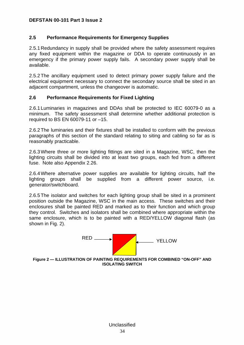
DEFSTAN 00-101 Part 3 Issue 2
Unclassified 34
2.5 Performance Requirements for Emergency Supplies
2.5.1 Redundancy in supply shall be provided where the safety assessment requires any fixed equipment within the magazine or DDA to operate continuously in an emergency if the primary power supply fails. A secondary power supply shall be available.
2.5.2 The ancillary equipment used to detect primary power supply failure and the electrical equipment necessary to connect the secondary source shall be sited in an adjacent compartment, unless the changeover is automatic.
2.6 Performance Requirements for Fixed Lighting
2.6.1 Luminaries in magazines and DDAs shall be protected to IEC 60079-0 as a minimum. The safety assessment shall determine whether additional protection is required to BS EN 60079-11 or –15.
2.6.2 The luminaries and their fixtures shall be installed to conform with the previous paragraphs of this section of the standard relating to siting and cabling so far as is reasonably practicable.
2.6.3 Where three or more lighting fittings are sited in a Magazine, WSC, then the lighting circuits shall be divided into at least two groups, each fed from a different fuse. Note also Appendix 2.26.
2.6.4 Where alternative power supplies are available for lighting circuits, half the lighting groups shall be supplied from a different power source, i.e. generator/switchboard.
2.6.5 The isolator and switches for each lighting group shall be sited in a prominent position outside the Magazine, WSC in the main access. These switches and their enclosures shall be painted RED and marked as to their function and which group they control. Switches and isolators shall be combined where appropriate within the same enclosure, which is to be painted with a RED/YELLOW diagonal flash (as shown in Fig. 2).
Figure 2 — ILLUSTRATION OF PAINTING REQUIREMENTS FOR COMBINED “ON-OFF” AND ISOLATING SWITCH
RED YELLOW
DEFSTAN 00-101 Part 3 Issue 2
Unclassified 35
2.7 Performance Requirements for Power Output Connectors
2.7.1 All power output connectors installed within the Magazine, WSC shall be socket only. Plugs and sockets shall be so designed to contain any arcing on make/break if disconnection could occur when equipment is energised. The method of achieving such protection shall conform to the requirements given in IEC 60079-0 or BS EN 50014.
2.8 Performance Requirements for Installed Test Equipment
2.8.1 Permanently installed test equipment necessary for carrying out electrical tests to assembled weapons shall meet the requirements of this standard.
2.8.2 Testing to be carried out with personnel alongside a weapon or munition shall meet the requirements of Def 07-85 ‘Issue 3 Design requirements for weapons and associated systems’ or OB Proc P108(1) for use with legacy systems only.
2.8.3 Firing circuits shall only be tested in accordance with OB Proc P101(2), where testing forms part of approved procedure.
2.8.4 A marker plate shall be fixed to test equipment stating that:
No maintenance work is to be carried out on this equipment with any of its circuits energised, when
weapons or explosives are in the compartment or are connected to the equipment.
DEFSTAN 00-101 Part 3 Issue 2
Unclassified 36
2.9 Performance Requirements for Electrically Controlled Handling Machinery
2.9.1 Electrically operated handling equipment installed in a Magazine, WSC shall meet the requirements of this standard. It shall also meet the requirements of JSP 467 where the load is lifted from above, or the Lloyd’s Register Code of Lifting Appliances in a Marine Environment (LAME Code) for weapon lifts. For other handling equipment that moves loads from underneath or traverses horizontally the relevant physical principles of JSP 467 shall also apply – see ACOP and Guidance in Def Stan 00-101 Part 1.
2.9.2 The equipment shall be earthed effectively. Continuous earth monitoring shall be provided. Loss of earth shall cause power supplies to the equipment to be shut down.
2.9.3 The equipment shall be energised only when either the magazine or the control position for the equipment is manned.
2.9.4 The construction of the equipment shall use materials that reduce the possibility of friction or impact generated sparks. The materials and earthing policy shall be such that the equipment does not build up electrostatic charge.
2.10 Performance Requirements for Safety-Related Devices
2.10.1 Safety devices shall function independently of any measurement or control devices required for normal operation.
2.10.2 Safety devices shall be designed to ensure that the system controlled “fails safe”.
2.11 Performance Requirements for Earthing
2.11.1 Provision shall be made to bond by positive connection any fixed equipment to the structure or earth net of the ship or submarine in the magazine or WSC. The earthing of intrinsically safe circuits shall be made according to IEC 60079-10. Def Stan 08-107/NES 501 and Def Stan 08-160 cover earth bonding of weapon stowage’s and magazine lockers sited on weather decks to ship structure.
DEFSTAN 00-101 Part 3 Issue 2
Unclassified 37
2.12 ACOP for Siting of Equipment
2.12.1 Whilst fixed equipment within the Magazine, WSC or DDA should be positioned to perform its design function as efficiently as possible, the siting should minimise interference to munition handling within the spaces.
2.12.2 Direct fitting of electrical equipment to the boundary bulkheads or deckhead of Magazines or WSCs should be avoided as far as is possible. Where equipment has to be fitted to the boundaries, it should be stood off by 70 mm (tolerance –10 mm) from their surfaces.
2.12.3 Where equipment is likely to be contacted by munitions or handling gear during magazine or DDA operations, its enclosure should be strengthened or guarded to limit damage. Such protection should be arranged to minimise every adverse effect on the operation, maintenance or inspection of the equipment. All metal guards should be effectively earthed.
2.12.4 Requirements for fitting of detectors in magazines and WSCs are given in Parts 1 and 2 of this Standard.
2.12.5 Parts 1 and 2 of this Standard also give guidance for the positioning of alarms operated by the detection equipment.
2.12.6 Small equipment such as power supply switch sockets, detectors, alarm devices etc may be directly mounted on boundaries in positions that are not vulnerable to damage. Power supply switch sockets should only be sited at test or working positions.
2.13 ACOP for Cabling
2.13.1 The general requirements for cabling should be in accordance with Def Stan 08-160.
2.13.2 Cables should be routed high in the magazine and provided with protection where necessary.
2.13.3 Cables should not be directly attached to the boundaries with the exception of lighting circuits and low power circuits such as alarms and damage control systems.
2.13.4 A notice should be displayed prominently that states: “The suspension of equipment/items from cables or fittings is prohibited”.
2.14 ACOP for Circuit Isolation
2.14.1 Other than local isolating switches for alarm and monitoring devices, which are normally required to be left ‘ON’, all other local isolating switches should be in the ‘OFF’ position when the Magazine, WSC is vacated. The switch marker plates provided should indicate the normal position.
DEFSTAN 00-101 Part 3 Issue 2
Unclassified 38
2.14.2 Local isolating switches for equipment in gun mountings/launchers should be sited outside the associated gun bay/power room.
2.15 ACOP for Emergency Supplies
2.15.1 Def Stan 08-160 requires redundancy (alternative) supply for ships where appropriate. Def Stan 08-109/NES 532 describes the requirements for separate generators to feed circuits that are routed through the ship in different cable runs within the hull. High priority weapon systems including magazine equipment should be provided with a switched alternative and/or emergency supply.
2.15.2 Some discontinuity in supply could be experienced if the reaction time to loss of power and the consequent switching times are too long, or if the ship is damaged in action. The effect of a discontinuity if it were to occur, such as loss of ventilation, should be assessed.
2.16 ACOP for Luminaries (Fixed Lighting)
2.16.1 IEC 60079-0 outlines the construction of the luminaries. Parts 11 and 15 of IEC 60079 give details of the construction, testing etc. of luminaries that can operate in potentially hazardous gas atmospheres. The luminaries should be considered to be fixed equipment (apparatus) in relation to the application of the IEC standards.
2.16.2 The siting of a luminarie within a magazine should take into account a number of demands. Firstly it has to illuminate the space adequately, secondly it has to be protected both from damage in operating the magazine and from being the cause of ignition within the magazine; thirdly it has to be accessible for replacement of the lamp (or lamps) within the luminaire; and finally it has to be protected from environmental stresses such as shock. The selected installation of luminaires should be justified particularly if the requirements of this standard cannot be met fully. Guidance is given below and in Def Stan 02-587
2.16.3 At least one luminaire in each manned magazine should remain functional in the event of a single circuit failure (see also Appendix 2.22).
2.16.4 Light fittings should be installed so as not to obstruct the normal stowage/movement of explosive stores. Protection should be given to any fitting that could be damaged in the course of such operation. Where mechanical protection is considered necessary, details are to be agreed at the earliest opportunity between the PIPT, Contractor and the Inspection Authority (previously Maritime Commissioning Trials & Assessment (MCTA)), and added to the compartment layout drawing.
2.16.5 The cabling for each lighting group, from the power source through to the light fitting, should be kept well separated from other lighting groups in the Magazine or WSC.
DEFSTAN 00-101 Part 3 Issue 2
Unclassified 39
2.17 ACOP for Power Output Connectors
2.17.1 The design of plugs and sockets should preclude arcs and/or contain them within enclosures. The design requirements of IEC 60079-0 or BS EN 50014 are to be followed.
2.18 ACOP for Test Equipment
2.18.1 The design of test equipment for use in Magazines or WSCs should follow the IEC BS EN standards in Appendix 1.14 & 1.15 above to ensure that it will not ignite a potential gas atmosphere within the magazine.
2.19 ACOP for Electrically Controlled Handling Machinery
2.19.1 In GRP vessels electrically controlled handling machinery should be earthed to the magazine earthing net.
2.19.2 The equipment should have disabling switches both at the control panel and at the external isolator. Emergency stop pushes should also be fitted where appropriate.
2.20 ACOP for Safety-Related Devices
2.20.1 Failure of a safety device should be detected sufficiently rapidly by appropriate technical means to ensure that there is only very little likelihood that dangerous situations will occur.
2.20.2 Emergency stop control of safety devices should be fitted with restart lockouts. A new start command may take effect on normal operation only after the restart lockouts have been intentionally reset.
2.20.3 Manual override should be fitted in order to shut down the equipment and protective systems incorporated within automatic processes that deviate from the intended operating conditions, provided that this does not further compromise safety.
2.20.4 In the event of a safety device failure, equipment and/or protective systems should, wherever possible, be secured in a safe condition.
2.20.5 Safety-related switching should activate the relevant control devices without intermediate software command.
2.21 ACOP for Earthing
2.21.1 A plan of the earthing arrangements within a magazine or WSC should be produced. This should ensure earth links are as short as possible and that earth loops are minimised. Although IEC 60079-14 deals mainly with earthing for intrinsically safe equipment, similar practices should be adopted for associated equipment including cabling. Details are to be included in the ships Datum Pack.
DEFSTAN 00-101 Part 3 Issue 2
Unclassified 40
2.22 Guidance on General Electrical Installation
2.22.1 Def Stan 08-160 states the general requirements for electrical installations in ships and submarines.
2.22.2 Small equipment as defined in IEC 60079-0 etc. can, after satisfactory assessment, be regarded as intrinsically safe in the given environment. For example, equipment of a passive nature can be so defined if it dissipates little heat and contains components that do not discharge energy or arc or spark beyond set minimum levels. Even electrical generators such as thermoelectric devices or photocells can be so classified if their electrical parameters, voltage, current, energy are insufficient to ignite the potential gas atmosphere.
2.23 Guidance on Siting of Equipment
2.23.1 Whilst fixed equipment within the Magazine, WSC or DDA should be positioned to perform its design function as efficiently as possible, it might have to be positioned where it causes interference to munition handing within the space. Parts 1 and 2 of this Standard require that the routes and handling equipment for munition stowage be identified and approved. Virtual reality computer modelling should be considered to avoid siting conflicts in the design of the Magazine, WSC or DDA. Advice is available from DSS NAExp.
2.23.2 The major hazard is a ship fire. The bulkhead and deckhead boundaries of the magazine are the last barrier between a potential fire and the munitions stowed within it. These boundaries should remain as free from attachments as possible so that their surface temperature remains approximately constant over its area, i.e. no hot spots should be developed. Mounting equipment on supporting brackets or other acceptable means will aid boundary cooling by convection in the event of a fire adjacent to the magazine. Heat transfer from equipment is also improved in normal operation. Some of the spacing could be used to provide shock mounting to decouple the equipment from ship’s structure. Additionally, boundary cooling by water and fire fighting within the magazine is easier as water can be directed to the bulkheads/deckheads more efficiently. See ACOP and Guidance in Parts 1 and 2 of this Standard.
2.23.3 In GRP vessels, the need for electrical equipment stand off is more finely balanced. The larger the equipment, the more important it becomes to stand off to allow boundary cooling to prevent a hot spot occurring behind the equipment in the event of an adjacent compartment fire. Hot spots in a GRP bulkhead will cause local delamination and breakdown of the GRP.
2.23.4 If the siting of the equipment cannot solve potential damage problems, then the enclosure should be designed to withstand accidental contact. The requirements of IEC 60079-0 and its relevant parts –11 and –15 should not be invalidated. Guards may be attached to the enclosure but should not interfere with equipment operation to an unacceptable degree. Metal guards are preferred as the use of non-conducting material could lead to an increased electrostatic hazard. Some account may also
DEFSTAN 00-101 Part 3 Issue 2
Unclassified 41
need to be taken as to the potential damage to munitions if they are to be handled in an unpackaged state.
2.23.5 Sockets should be provided only for functions that are approved as suitable to be carried out within the magazine.
2.24 Guidance on Cabling
2.24.1 Def Stan 08-160 states the general requirements for the installation of cables in ships. Cable runs are best routed high within magazines to avoid damage from contact with munitions during handling. Protection may still be necessary however as indicated in the above standard. This also avoids potential faults following flooding. There is no restriction on routing on bulkheads/deckheads. Cables however should not be directly attached to the boundaries with the exception of lighting circuits and low power circuits such as alarms and damage control systems, providing the installation will meet the environmental requirements. High power circuits should be carried in cable carriers/trays.
2.24.2 Guidance on rating of cables is given in Def Stan 02-512 and the IEE Regulations for the Electrical and Electronic Equipment of Ships.
2.24.3 A ship fire is a major hazard to magazine safety. The surrounding boundaries of a Magazine or WSC should provide an effective barrier to its progress. Penetration of the boundaries to provide cable routes from adjacent compartments should be minimised. The packing through which cabling passes should be of fire proof materials as well as pressure tight to the same standard as the Magazine, WSC or DDA.
2.24.4 If cables that do not provide a service within a Magazine, WSC or DDA are excluded they do not contribute to the hazard from fault/failure or electromagnetic coupling. If transit is necessary, a continuous run, in which screening and protection are also unbroken across the Magazine, WSC or DDA, minimises risk.
2.24.5 An assessment needs to address the function of the cable to decide whether the screening and/or protection to be installed are adequate.
2.24.6 Cabling that has a route or origin from decks that are exposed to the external electromagnetic environment generated by own or other ship’s radiating antenna, natural effects such as lightning or NEMP can carry induced currents. These may be sufficient to cause damage or upset in electrical equipment, particularly the electronic content. Damage or initiation of firing circuits in munitions may also be possible. However the design requirements for munitions, Def Stan 07-85, should ensure that munitions are protected against such environments. Whilst screening may be effective against electromagnetic radiation, it is not effective against the large magnetic fields associated with a cable used for ship’s degaussing if it were to be routed through a Magazine, WSC or DDA. It is recommended that the routing of such a cable does not include these areas. If magazine equipment or munitions stowed within the magazine are susceptible to such environments, then no other
DEFSTAN 00-101 Part 3 Issue 2
Unclassified 42
choice than excluding the munition from the area is possible where such cabling has to pass through the area.
2.24.7 Separation of power cables from other cables in magazines should be by at least 100 mm in ships with an ITT for design later than 1 Jan 06. In current In-Service ships, it is accepted that the very small number of power cables are run with other cables. In submarine WSCs, separation of power cabling for equipment within the WSC may not be practicable. However power cabling for services in other compartments should not pass through the WSC.
2.24.8 In general, the risks from cabling with voltages above 450 V in the vicinity of a magazine are difficult to justify in the event of action damage since they may provide a source of fire ignition. Likewise, the electromagnetic radiation from such cabling may present a hazard to damaged weapons containing EEDs (e.g. in a guided weapon magazine). In principle, medium voltage (MV) cabling associated with surface ship main propulsion should not be routed through magazine areas. In any event, separation of MV cables from other cables should be by at least 300 mm up to 11 kV and 500 mm for 15 kV. Further guidance is given in Def Stan 02-607. Guidance on creepage and clearance between conductors of MV cables is given in Def Stan 08-109. Any use of cabling above 450 V near a magazine should be justified in the SESC.
2.24.9 When firing circuits provide a service such as rapid initiation of damage control or blast mitigation equipment or simply pass through the area, they should be protected from external influences such as faults or failures in other systems or from electromagnetic radiation. OB Proc P101 (2) requires individual screened cables (usually twisted pair). These in turn are housed in conduit, which may be routed with other cabling in the magazine. The termination of a firing circuit within the magazine should also be enclosed in protective screening. This enclosure should also contain any debris or gas content if the electro-explosive device were to be operated.
2.24.10 It is good practice to separate cables associated with intrinsically safe circuits from other cables by at least 50 mm. Further guidance is given in the IEE Regulations for ships.
2.24.11 Restricting the use of loose cable within Magazines, WSCs or DDAs limits the possibility of inadvertent damage and disconnection. Cable protection can alleviate the risk of damage.
2.24.12 Metal conduit should be earthed and electrically continuous across all joints. Conduit should include a facility to drain any accumulation of water at the lowest point(s). Where such drains are in magazines they should be fitted with a screwed plug and keep chain in accordance with Def Stan 08-160.
2.24.13 Travelling cable should be sheathed overall with a flame retardant layer [BS 6977]. Where these cables are moving wholly or partially in a hazardous area a metallic screen should be applied immediately under the outer sheath. Guidance is given in BS EN61386-1: 2004.
DEFSTAN 00-101 Part 3 Issue 2
Unclassified 43
2.25 Guidance on Circuit Isolation
2.25.1 Isolation on all poles of an electrical circuit prevents extraneous power from any inadvertent source or from electromagnetically induced currents coupled upstream of the isolator, being delivered to Magazine, WSC or DDA equipment.
2.25.2 An enclosed air break multipole switch operated by hand is probably the most reliable and efficient isolator. The use of any other system is to be justified in the SESC. The isolators should ideally be placed outside the Magazine or DDA since, if inside, they would have to meet the requirements of IEC 60079-14. Most air break switches produce arcs on “make or break”. Additionally not all electrical circuits are required to operate continuously when the magazine or DDA is inactive. Checking on the status of equipment can be done without entering the locked magazine.
2.25.3 Circuits that monitor the environmental status perform safety functions or provide internal communications are required usually to operate continuously whether or not the magazine or DDA is occupied by personnel. Ideally, such circuits operate on low power (less than 1 W) and at low voltage (24 V or less). Such levels may be sufficiently low as to be considered adequate to operate within the magazine without extensive protection, particularly if the magazine equipment is passive and/or contains components which neither radiate very much heat nor produce arcs and sparks. The IEC standards should still be regarded as the definitive source in these considerations.
2.25.4 The means of preventing restoration of power should be compatible with the Tag Out system. A simple lockout device may suffice. Guidance is given in BR 200 on the operation of the “Tag Out” system.
2.25.5 All circuits within the magazine should be identified and their functions clearly marked. It is important that circuits that do not have local isolators be identified on markers adjacent to those that have isolators.
2.26 Guidance on Fixed Lighting
2.26.1 Past experience of action damage shows that fuses are particularly vulnerable. Feeding of different lighting groups from different fuse boxes helps to provide maximum redundancy in a large magazine – see guidance in Def Stan 02-587. Separation of cables from different groups helps to prevent loss of lighting due to minor splinter damage.
2.26.2 Def Stan 08-160 requires an alternative power supply to be separate from its partner so that damage from enemy action need not result in total loss of power supplies to essential services. Multiple redundancy may be possible in some circumstances but multiple cable runs are impracticable hence the limitation to two sources of supply. Emergency lighting will also be supplied, see Appendix 4.3.
DEFSTAN 00-101 Part 3 Issue 2
Unclassified 44
2.26.3 Mounting, height, supplies and marker plates for luminaires should be in accordance with Def Stan 02-587. Light fittings should be watertight to 0.1 bar (10 kPa). [Suitable types of luminaires are expected to be given in the update to Def Stan 02-587. In the meantime advice should be sought from MLS IPT.]
2.27 Guidance on Power Output Connectors
2.27.1 Power connectors are considered to be fixed equipment in relation to the application of the IEC standards. Guidance on methods for achieving this requirement for high and low power installations is given in IEC 60079-0 or BS EN 50014.
2.27.2 Sockets are preferred for power output connectors because the connectors are shrouded and it is thus more difficult to short them out producing an arc if a metallic object is introduced.
2.28 Guidance on Test Equipment
2.28.1 Maintenance of test equipment should ideally not take place in the magazine. Removal to a workshop is recommended. Removal of weapons and munitions may be difficult to achieve once ammunitioned, so it is better if the test equipment is designed as being easily demountable.
2.29 Guidance on Electrically Controlled Handling Machinery
2.29.1 Electrically controlled handling equipment covers both that used for moving munitions in/out of the stowage or Magazine, WSC or DDA and that used to select, convey, load etc. in an automatic or semi-automatic feed or loading system. This includes Mobile Mechanical Handling Equipment (MMHE) used for munition handling. The delineation of the transition from magazine or DDA to external areas is dealt with in Parts 1 and 2 of this Standard.
2.29.2 Loss of earth means that the equipment becomes electrically isolated. Charge differences between materials within the magazine can lead to substantial arcs occurring when the materials are brought together.
2.29.3 Moving parts increase the possibility of charging materials; the earthing policy should account for possible enhanced charge accumulation, particularly on non-metallic parts.
2.29.4 Fluids under pressure in hydraulic systems and MMHE can form mists. These mists should not be easily ignitable. The material chosen should be Class A in the Annex to IEC 60079-0.
2.29.5 Care is required to ensure that the MMHE control system and the operator controls are suitable for the expected duty cycle and the frequency of operation.
2.29.6 Enclosures that can be opened more quickly than the time necessary for an ignition source to become non-effective, (e.g. to allow the cooling of enclosed hot
DEFSTAN 00-101 Part 3 Issue 2
Unclassified 45
parts to a surface temperature below the temperature class or the marked temperature of the equipment) should be marked with the warning:
“AFTER STOPPING, DELAY X MINUTES BEFORE OPENING”
“X” being the value in minutes of the delay required.
Alternatively the equipment may be marked with the warning:
“DO NOT OPEN WHEN AN EXPLOSIVE ATMOSPHERE IS PRESENT”
This information shall be included in the instructions for use.
DEFSTAN 00-101 Part 3 Issue 2
Unclassified 46
APPENDIX 3 DESIGN REQUIREMENTS FOR ADJACENT COMPARTMENTS
3.1 Description
3.1.1 Adjacent compartments have decks, deckheads or bulkheads in common with a magazine or armament hold.
3.1.2 Electrical requirements for adjacent compartments also apply in part to compartments that have a contiguous connection to a magazine or armament hold because they diagonally abut the magazine/armament hold. Such compartments are described as indirectly adjacent to a magazine/armament hold.
3.2 Performance Requirements for Electrical Design in Adjacent Compartments
3.2.1 The electrical equipment and installation of electrical equipment in adjacent compartments to a Magazine or WSC are to be in conformance with Def Stan 08-107/NES 501 and Def Stan 08-160. Appropriate measures are to be taken to reduce risks to munitions from electrical equipment in adjacent compartments to ALARP.
3.2.2 The relevant elements of the electrical design shall be detailed and justified in the SESC. Guidance is given below.
3.2.3 Adjacent compartments must also meet the explosives SMS and SSOW requirements of JSP 862, other SEMS and Key Hazard areas as appropriate.
3.3 Performance Requirements for Electrical Equipment in Adjacent Compartments
3.3.1 Electrical equipment shall not be installed in adjacent compartments unless an assessment shows that the fire risk is acceptable.
3.3.2 Equipment enclosures shall provide protection against environmental conditions within the area and conform to any fire fighting and damage control requirements.
3.4 Performance Requirements for Electrical Installation in Adjacent Compartments
3.4.1 Cables passing through the adjacent compartment, but not associated with equipment within it shall be continuous and are not to be mounted on the boundary bulkheads/deck/deckhead of the magazine so far as is practicable. The hazard analysis may indicate that extra protection is necessary.
3.4.2 Electrical equipment shall not to be mounted on the common boundary with the magazine unless it is impractical to mount it elsewhere. Where it is unavoidable, equipment shall to be stood off by at least 70 mm (-10 mm tolerance) to assist boundary cooling. Cabling, however, can be secured to the bulkheads where it provides a service to equipment installed here or in the magazine.
DEFSTAN 00-101 Part 3 Issue 2
Unclassified 47
3.4.3 In GRP ships, equipment shall be mounted on the bulkhead providing the attachments do not penetrate the bulkhead or unless the equipment covers more than 25% of the bulkhead or contains switching equipment operating at voltages of 220 V or above.
3.4.4 Where firing circuits are routed in adjacent compartments they shall be protected by steel conduit to BS4568-1: 1970 & BS EN61386-1: 2004 and meet the requirements of OB Proceeding P101 (2).
3.5 Performance Requirements for Smoke/Heat Detection Equipment in Adjacent Compartments
3.5.1 Requirements for fitting of detectors in adjacent compartments are given in Parts 1 and 2 of this Standard.
3.5.2 Parts 1 and 2 of this Standard also give requirements for the positioning of alarms operated by the detection equipment.
3.6 ACOP for Special Requirements in Adjacent Compartments
3.6.1 The assessment of risks arising from the siting of electrical equipment in adjacent compartments should lead to the elimination of equipment on the boundary so far as is reasonably practicable.
3.6.2 No special measures in the design of enclosures of electrical equipment in adjacent compartments are necessary beyond those required for environmental protection and firefighting. Equipment on the adjacent bulkhead of a magazine may be subjected to boundary cooling.
3.7 ACOP for Special Requirements for Installation in Adjacent Compartments
3.7.1 The requirements and guidance for cabling in Appendices 2.3 should apply also to cabling on the magazine boundaries of adjacent compartments so far as is practicable.
3.7.2 Magazine boundaries should be protected as far as possible from reaching high temperatures. The boundary bulkhead/deckhead should be considered to be a fire barrier. Mounting equipment at stand off distances from the boundary will allow the boundary to cool – see ACOP at Appendix 2.11 above and Guidance at Appendix 2.21 and below.
3.7.3 Stand off of equipment in GRP ships – see Guidance at Appendix 2.21 above.
DEFSTAN 00-101 Part 3 Issue 2
Unclassified 48
3.8 ACOP for Smoke and Heat Detection Equipment
3.8.1 Smoke and heat detectors should be fitted in compartments adjacent to Magazines, Armament Holds, WSCs and small magazines. Detailed requirements are given in Parts 1 and 2 of this Standard.
3.9 Guidance on Electrical Equipment in Adjacent Compartments
3.9.1 The primary risk to magazines from electrical equipment fitted in adjacent compartments is that of fire which can raise the temperature of the magazine boundary. Mounting a minimum of equipment on the boundary will reduce risk. Stand-off of equipment will aid the efficiency of boundary cooling. An assessment of fire risk caused by electrical fault or failure of equipment within the compartment should be made. Installing only that equipment required by the systems which function within the compartment obviously aids risk reduction.
3.9.2 Provision of heat detectors in addition to smoke detectors will improve response time.
3.9.3 Provision of adequate smoke and heat detectors in adjacent compartments, linked to suitable alarms, will help to reduce fire risks.
DEFSTAN 00-101 Part 3 Issue 2
Unclassified 49
APPENDIX 4 DESIGN REQUIREMENTS FOR TEMPORARILY INSTALLED EQUIPMENT
4.1 Description
4.1.1 This paragraph sets out the Performance Requirements, ACOP and Guidance that relate to the requirements for temporarily installed electrical equipment in Magazines or WSCs, small magazines and vertical launch silo magazines in ships and submarines.
4.2 Performance Requirements for Portable Equipment
4.2.1 Portable equipment taken into magazines, WSCs or DDAs (when munitions are present) shall be designed to the requirements of this standard. The requirements given in Appendix 2.8.2 to 2.8.4 shall be met. Proof of compliance shall be provided to NAexp. NAexp will consider approval of such equipment in accordance with the guidance below.
4.2.2 When not in use, the equipment shall be disconnected, stored and secured in its designated stowage. Portable lighting/equipment shall be stored outside the magazine in an adjacent compartment. Use of portable equipment shall be kept to minimum so as to reduce to ALARP the risks to munitions in ships.
4.2.3 Portable equipment approved for use in a magazine shall be included on the S285K (list of permitted contents of the magazine).
4.2.4 The portable equipment design shall also meet the general explosives SMS and the SSOW requirements of JSP 862, other SEMS and Key Hazard areas as appropriate. The duty holder shall take measures to ensure all relevant requirements are satisfied.
4.3 Performance Requirements for Emergency Lighting
4.3.1 Emergency lighting shall be provided for each Magazine, but not for Small Magazines as defined by Parts 1 & 2 of this Standard. Where the emergency lighting chosen is Cyalume Chemical Illuminators (CCI), these shall be stowed, together with their associated Magnetic Base Holders and Combat Light Devices (light shields), in a dedicated locked stowage box in accordance with Part 1 of this Standard. Emergency lighting arrangements are not mandatory for RFA and NAV Armament Cargo Holds, or in the holds of Naval Armament Lighters.
4.3.2 Emergency lighting arrangements shall be provided in manned gun mountings.
4.4 ACOP for Temporarily Installed Equipment
4.4.1 Any equipment taken into a magazine should be certified as safe to use. No surface temperature should be greater than the limit approved for the potential gas atmosphere associated with the munitions and explosives to be stowed. The equipment should not produce arcs or sparks that could ignite such an atmosphere.
DEFSTAN 00-101 Part 3 Issue 2
Unclassified 50
Additionally, any other appropriate requirements from Defence Standards 08-107, 08-160 or JSP 862 should be met.
4.4.2 Temporary electrical equipment should not be stowed in a magazine or WSC.
4.4.3 The earthing of temporarily installed equipment needs consideration – see ACOP in Appendix 2.21.
4.4.4 Advice may be sought from DSS NAExp where there is a requirement for electrical installations in ISO containers that are to be used on the weatherdeck for the temporary stowage of munitions.
4.5 Guidance on Temporarily Installed Equipment
4.5.1 Maintenance of any portable equipment within magazine spaces could mean that parts of the equipment could become exposed without protection of its enclosure and hence present a hazard.
4.6 Guidance on Compliance for Portable Equipment
4.6.1 Requests for approval for use of temporary equipment in a magazine should in the first instance forwarded to the relevant Platform IPT who will carry out a Risk Assessment for its use and forward to NAExp for agreement and amendment of Certification as required. The request should include a simple summary assessment of the risk of introducing the equipment into the magazine. For Zone 2 Magazines, the request should be accompanied by the EC declaration of conformity for the proposed equipment in accordance with the ATEX Directive. The request is to contain the following information as a minimum:
Table 2 Compliance/Conformity Matrix
Requirement Remarks
Zone 2 Magazine Remarks
Non Zone 2 Magazine Name or identification mark and the address of the manufacturer or his authorised representative in the EC.
A description of the equipment. A product description (e.g. Hazardous Gas Meter Type 123) and its intended use. For an assembly, list any items that have been assessed separately as ATEX equipment in their own right. If necessary, include an explanation of the operation of the equipment. Design and/or manufacturing drawings may be included.
A product description and its intended use. If necessary, include an explanation of the operation of the equipment. Design and/or manufacturing drawings may be included.
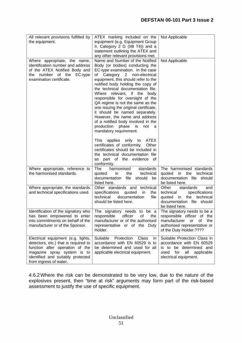
DEFSTAN 00-101 Part 3 Issue 2
Unclassified 51
All relevant provisions fulfilled by the equipment.
ATEX marking included on the equipment (e.g. Equipment Group II, Category 2 G (IIB T4)) and a statement outlining the ATEX and any other relevant provisions met.
Not Applicable
Where appropriate, the name, identification number and address of the ATEX Notified Body and the number of the EC-type examination certificate.
Name and Number of the Notified Body (or bodies) conducting the EC-type examination. In the case of Category 2 non-electrical equipment, this should refer to the notified body holding the copy of the technical documentation file. Where relevant, if the body responsible for oversight of the QA regime is not the same as the one issuing the original certificate, it should be named separately. However, the name and address of a notified body involved in the production phase is not a mandatory requirement. This applies only to ATEX certificates of conformity. Other certificates should be included in the technical documentation file as part of the evidence of conformity.
Not Applicable
Where appropriate, reference to the harmonised standards.
The harmonised standards quoted in the technical documentation file should be listed here.
The harmonised standards quoted in the technical documentation file should be listed here.
Where appropriate, the standards and technical specifications used.
Other standards and technical specifications quoted in the technical documentation file should be listed here.
Other standards and technical specifications quoted in the technical documentation file should be listed here.
Identification of the signatory who has been empowered to enter into commitments on behalf of the manufacturer or of the Sponsor.
The signatory needs to be a responsible officer of the manufacturer or of the authorised representative or of the Duty Holder.
The signatory needs to be a responsible officer of the manufacturer or of the authorised representative or of the Duty Holder.????
Electrical equipment (e.g. lights, detectors, etc.) that is required to function after operation of the magazine spray system is to identified and suitably protected from ingress of water.
Suitable Protection Class in accordance with EN 60529 is to be determined and used for all applicable electrical equipment.
Suitable Protection Class in accordance with EN 60529 is to be determined and used for all applicable electrical equipment.
4.6.2 Where the risk can be demonstrated to be very low, due to the nature of the explosives present, then “time at risk” arguments may form part of the risk-based assessment to justify the use of specific equipment.
DEFSTAN 00-101 Part 3 Issue 2
Unclassified 52
APPENDIX 5 ELECTROMAGNETIC INDUCTION, RADIO FREQUENCY AND ELECTROSTATIC HAZARDS
5.1 Description
5.1.1 Munitions/explosive stores may be subject to inadvertent initiation or safety failures as a result of exposure to unexpected levels of electromagnetic induction, radio frequency energy or electrostatic hazards. This appendix sets out the Performance Requirements, ACOP and Guidance that relate to the general requirements to reduce such hazards to levels that are ALARP and tolerable in Magazines, WSC and DDAs.
5.2 Performance Requirements for Design to Reduce Electromagnetic Induction, Radio Frequency and Electrostatic Hazards
5.2.1 The overall electromagnetic and electrostatic environment within a Magazine, WSC or DDA shall be assessed. The equipment within the magazine shall be designed to withstand the overall environment. Guidance on the environment is given in Def Stan 08-46. The precautions to be taken against environmental inadvertent initiation of any electro-explosive device (EED) within the magazine are given in BR 2924 and OB Proceeding P101 (2).
5.2.2 Equipment to be used in Magazines, WSCs and DDAs shall, in addition, not degrade the proper functioning of other equipment in the ship or magazine or cause a risk to the stowed munitions or installed weapon systems. Electromagnetic compatibility studies and testing shall address both conducted and radiated emissions and susceptibilities. Def Stan 59-411, [Parts 1, 2, 3, 4, 5, and 7] shall be used to determine a test programme for the equipment before installation that relates to the environments arising from the assessment.
5.2.3 Potential upset to equipment in magazines from power supply surges, discontinuities or transients shall be assessed. Test procedures are given in Def Stan 59-411 Part 3.
5.2.4 The requirements for a conducting deck as an electrostatic precaution are detailed in Part 1 Appendix 15 of this Standard. Some DDAs shall not require a special conducting deck depending upon magazine usage. The earthing requirements for equipment are given in Appendix B.11.
5.2.5 The potential effects of a lightning strike on the ship shall be assessed with respect to any damage or effect on equipment in or associated with the magazines. The transient test procedure given in Def Stan 59-411 may be applicable in simulating induced effects.
5.2.6 Where a nuclear electromagnetic pulse (NEMP) threat is detailed in the URD/SRD and/or the Platform Policy Paper, the potential effects of a NEMP associated with the explosion of a nuclear weapon are to be assessed with respect to any damage or effect on the equipment in or associated with the magazine. Def Stan 08-4 gives guidance on testing of equipment and protection where considered
DEFSTAN 00-101 Part 3 Issue 2
Unclassified 53
necessary. Def Stan 02-529/NES 529 gives guidelines on hardening for the naval scenario.
5.2.7 The precautions incorporated within the design shall be detailed and justified in the SESC.
5.2.8 The general electromagnetic, rf and electrostatic precautions in magazines, WSC and DDA must also meet the SMS and SSOW requirements of JSP 862, other SEMS and Key Hazards as appropriate. The duty holder shall take measures to ensure all relevant requirements are satisfied.
5.3 ACOP for Electromagnetic Induction, Radiation and Electrostatic Hazards
5.3.1 Any equipment installed or temporarily used within Magazines, WSCs and DDAs should be compatible with the overall electromagnetic environment. See below for detailed guidance and guidance on GRP vessels.
5.3.2 Def Stan 21-27/NES 1027 gives the design requirements that should ensure electromagnetic compatibility between equipments installed in the Magazine or WSC. Special earthing requirements may be necessary for systems operating at radio frequencies.
5.3.3 Faults or failures introduced by surges, discontinuities and other transients are particularly significant for equipment to meet IEC 60079 standards. Def Stan 59-411 Part 3 contains appropriate tests.
5.4 Guidance on Electromagnetic Induction, Radiation and Electrostatic Hazards
5.4.1 As Magazines and WSCs are usually contained within metal boundaries, little of the external environment penetrates directly into the space – still less if all bulkhead closures are shut. The environment is thus composed of that self-generated by installed equipment that imported along cables feeding equipment within the compartment, or others that transit the compartment. This environment should pose little hazard to complete munitions and all-up rounds (AURs) but could be a problem if weapons are disassembled, or are being tested or are damaged in action. It is a further reason for minimising cables that transit the compartment. See also Appendix 2.22.
5.4.2 Weapon Parks or stowage’s on the upper deck, whether temporary or semi-permanent, are more open to the external environment mainly resulting from own ship’s communication and radar systems. Use of metal RU lockers and siting weapon parks in positions where the ship’s structure provides some shielding are useful in providing protection to munitions and personnel.
5.4.3 The electrostatic hazard is a particular difficulty within magazines. The establishment of an earthing policy is essential. The aim is to maintain all equipment, munitions and personnel at the same potential before, during and after any handling
DEFSTAN 00-101 Part 3 Issue 2
Unclassified 54
of munitions. The presence of non-conducting material within the compartment is an issue as charge can build up on its surfaces. Moving machinery can also create electrostatic charge. A special conducting deck is required where EED’s are to be handled and assembled into explosive devices. Procedure plays a considerable part in risk reduction - see JSP 862 and BR 2924.
5.4.4 A direct lightning strike will usually connect to a ship at a high point. The discharge currents will be channelled into the ship’s structure hence reducing the destructive effect of the very large electric current. This flow is unlikely to affect Magazines or WSCs directly. It does however generate a powerful electromagnetic pulse that may couple with cables servicing or transiting the magazine area. A ship wide assessment of the potential effects of a lightning strike should be made. Any magazine that requires protection should be identified for such an assessment.
5.4.5 The NEMP associated with a nuclear explosion can cause damage and upset to electrical and electronic systems in ships. A metal ship’s structure attenuates the direct effect considerably but the indirect effects caused by electromagnetic coupling with exposed cables can import transients within the structure. Def Stan 08-4 gives a wide appreciation of the effects produced by a nuclear explosion. Def Stan 08-108/NES 529 should be consulted for guidance on nuclear hardening in the naval scenario.
5.4.6 Electromagnetic compatibility for equipment in a GRP ship should be considered carefully as electromagnetic radiation levels within the magazine or DDA will be higher. The ship’s structure no longer acts as a totally effective Faraday shield and will have susceptibility at certain frequencies and generally higher leakage. Additionally cabling entering the magazine area will carry enhanced induced currents. Electromagnetic compatibility may become a significant issue. The establishment of the external environment for such a ship is essential for a full EMC assessment to be made.
DEFSTAN 00-101 Part 3 Issue 2
Unclassified 55
APPENDIX 6 POTENTIALLY HAZARDOUS ENVIRONMENTS OF A SPECIAL NATURE
6.1 Description
6.1.1 This appendix sets out the Performance Requirements, ACOP and Guidance that relate to the electrical design safety and installation requirements to reduce potentially hazardous environments of a special nature to levels that are ALARP and tolerable in magazines, WSC and DDAs in MOD ships and submarines.
6.2 Performance Requirements for Potentially Hazardous Environments of a Special Nature
6.2.1 Appropriate measures shall be taken to reduce to ALARP the risks to munitions onboard MOD ships from potentially hazardous environments of a special nature.
6.2.2 The measures taken shall be detailed in the design. Design safety justification for measures shall be detailed in the SESC. Guidance on appropriate design is given below. The main measures should be summarised in the SESC.
6.3 Performance Requirements for Degaussing Cables
6.3.1 Equipment installed in Magazines, WSCs and DDAs through which degaussing cables have to be routed shall withstand the Magazine, WSC or DDA field strengths in accordance with Def Stan 00-101 Part 4 (GNE).
6.4 Performance Requirements for Waveguides
6.4.1 Waveguides shall not to be routed through a Magazine, WSC so far as is reasonably practicable.
6.5 Performance Requirements for Cranes
6.5.1 Cranes on the upper deck used for lifting of explosives shall meet the requirements of BR 3027 and JSP 467 and the electrical requirements of Def Stan 08-107/NES 501 and Def Stan 08-160.
6.6 Performance Requirements for Ship to Shore Electrical Connections
6.6.1 Ship-to-shore electrical connections shall be separated from any Weapon Launcher Tube or Container, or Magazine Locker by as far as is reasonably practicable.
6.7 ACOP for Waveguides
6.7.1 Unless it is impracticable to site them elsewhere, waveguides should not be routed through a magazine. However, if the efficiency of the associated equipment would be impaired unacceptably by re-routing around the magazine, then a route
DEFSTAN 00-101 Part 3 Issue 2
Unclassified 56
through a magazine can be adopted provided the criteria in 6.7.2 and 6.7.3 can be met. The design safety justification is to be included in the SESC.
6.7.2 If a waveguide is to pass through the magazine then it should be continuous without connections. It should be enclosed in a continuous metal trunk.
6.7.3 The access to the waveguide should be from the outside of the magazine with the trunking forming a pocket within the magazine. This trunking is to be welded to the boundaries of the magazine. If these arrangements are not possible, the trunking is to be constructed as for rf tight cable trunks in accordance with SDN-006-050 197 with internal access plates.
6.8 ACOP for Cranes
6.8.1 Where cranes on the Upper Deck are used for the lifting of explosives, the operating machinery should be electrically screened and provided with earthing arrangements and lightning conductors. Detailed requirements are given in BR 3027 and JSP 467 and electrical requirements in Def Stan 08-107/NES 501 and Def Stan 08-160.
6.9 ACOP for Ship to Shore Electrical Connections
6.9.1 The distance should be sufficient to prevent any hazard to munitions. A distance of 2 m from upper deck magazine lockers is adequate for 440 V, provided cables are protected from damage. Otherwise a 6 m separation is required.
6.10 ACOP for Earthing of Weapon Containers
6.10.1 Appropriate earthing points for Weapon Containers are required dependant upon the weapon carried.
6.11 Guidance on Degaussing Cables
6.11.1 A degaussing cable forms a coil that carries a large current of a periodic nature, which produces a very large magnetic field. Equipment cannot be shielded from fields of this nature. Survivability may be enhanced by not operating the equipment during degaussing, but this will not be practicable for mission essential equipment.
6.11.2 Best practice is not to run degaussing cables in magazines. Where it is essential to route degaussing cable through magazines and WSCs they should not be run within 1 m of any weapon stowage position or weapon control equipment.
6.12 Guidance on Waveguides
6.12.1 Leakage of microwave energy from a waveguide could cause a hazard that is unacceptable to munitions (or personnel). Hence exclusion reduces risk. However waveguide losses are reduced if waveguides are short and straight. If the route is through the magazine, it should be enclosed either in a solid metal trunk or an rf tight trunk.
DEFSTAN 00-101 Part 3 Issue 2
Unclassified 57
6.13 Guidance on Ship to Shore Connections
6.13.1 Ship to shore connection boxes should be sited away from weapon launchers, upper deck magazine lockers and magazines. A distance of 2 m should be sufficient to prevent damage arising by direct contact or induction from 440 V cables and from the connection box. If higher voltage connections are made, a safe distance should be calculated and justified in the SESC.

DEFSTAN 00-101 Part 3 Issue 2
Unclassified 58
APPENDIX 7 Electrical Requirements for ISO Containers
7.1 Description
7.1.1 It is feasible that ISO Containers could be sited on the weatherdeck of suitable STUFT vessels to provide additional stowage for transportation of munitions in time of tension or war.
7.1.2 This appendix sets out the Performance Requirements, ACOP and Guidance that may be used to assistant in the reduction of such associated electrical hazards to levels that are ALARP and tolerable.
7.2 ACOP for Earthing of ISO Containers
7.2.1 ISO containers placed temporarily on the upper deck in which packaged munitions are stowed for transportation require a minimum of electrical installation. Large containers (e.g. 20 and 40 ft ISO containers) need only smoke and heat detectors to be installed. Smaller containers may not need any detectors. As entry to the containers will be minimal, the use of emergency (i.e. hand held) lighting should be sufficient. Chains are to be used to lash the containers to the deck. Good metallic contact between the chains and the deck rings or lashing points should be made. The electrical contact resistance is to be low enough to ensure that charge does not build up on the container.
7.2.2 The cabling to the smoke and heat detectors in containers should be protected from the upper deck environment including potential damage from ship operations. The detectors should be connected to the ship central alarm system if practicable, or to a suitable remote alarm in a manned area.
7.3 Guidance on Earthing of ISO Containers
7.3.1 Any hazard from electrostatic discharge is likely to be negated if the contents, its stowage, installation and the ship’s structure are maintained at the same potential. Where a metal container is used that can maintain adequate electrical contact with the stowage that should be sufficient.
7.3.2 In the particular case of metal ammunition containers stowed on wooden pallets, it should be sufficient to earth the pallet load prior to any handling operations. The ammunition containers are unlikely to build up significant charge if they are not being handled. 7.3.3 Containers used for temporary stowage of munitions on the upper deck should be all metal containers to provide EMC protection. Wooden chacons are not suitable. The chains used for lashing should provide an adequate leakage path to prevent build up of an electrostatic charge.
DEFSTAN 00-101 Part 3 Issue 2
Unclassified 59
ANNEX A - RELATED DOCUMENTS
Ref No
Reference Title
IMDG International Maritime Dangerous Goods Code IEC 60079-0 Electrical Apparatus for Explosive Gas Atmospheres - General
Requirements IEC 60079-1 Flameproof Enclosures “d” IEC 60079-2 Pressurised Enclosures “p” IEC 60079-3 Spark Test Apparatus for Intrinsically Safe Circuits IEC 60079-4 Method of Test for Ignition Temperatures IEC 60079-5 Powder filling “q” IEC 60079-6 Oil Immersion “o” IEC 60079-7 Increased safety “e” IEC 60079-10 Electrical Apparatus for Explosive Gas Atmospheres - Classification of
Hazardous Areas. IEC 60079-11 Intrinsic Safety “i” IEC 60079-14 Electrical Apparatus with Type of Protection “n” IEC 60079-18 Encapsulation “m” IEC 60079-20 Data for Flammable Gases and Vapours IEC 60529 Degree of Protection Provided by Enclosures (IP Code) PD 60079-4 Guide to the application of IEC 60079-14 STANAG 4439 Policy for Introduction, Assessment and Testing for Insensitive
Munitions (MURAT) AOP-15 Guidance on the assessment of the Safety and Suitability for Service
of Non-Nuclear Munitions for NATO Armed Forces AOP-39 Guidance on the Development, Assessment and Testing of Insensitive
Munitions (MURAT) BS EN 13463 Non-electrical equipment for potentially explosive atmospheres BS EN 50014 Electrical Apparatus for Potentially Explosive Atmospheres - General
Requirements BS EN 50015 Electrical Apparatus for Potentially Explosive Atmospheres Oil
Immersion “o” BS EN 50016 Electrical Apparatus for Potentially Explosive Atmospheres
Pressurisation “p” BS EN 50017 Electrical Apparatus for Potentially Explosive Atmospheres Powder
Filling “q” BS EN 50018 Electrical Apparatus for Potentially Explosive Atmospheres Flameproof
Enclosure ‘d’. BS EN 50019 Electrical Apparatus for Potentially Explosive Atmospheres Increased
Safety “e” BS EN 50020 Electrical Apparatus for Potentially Explosive Atmospheres Intrinsic
Safety ‘i’. BS EN 50021 Electrical Apparatus for Potentially Explosive Atmospheres Type of
Protection ‘n’. BS EN 50028 Encapsulation “m” BS EN 60079-14 Electrical Apparatus for Potentially Explosive Atmospheres - Electrical
Installations in Hazardous Areas (other than mines) BS EN 60529 Specification for Degrees of Protection Provided by Enclosure (IP
Code) BS EN61386-1:
2004 Conduit systems for cable management. General requirements
BS4568-1: 1970 Specification for steel conduit and fittings with metric threads of ISO form for electrical installations. Steel conduit, bends and couplers
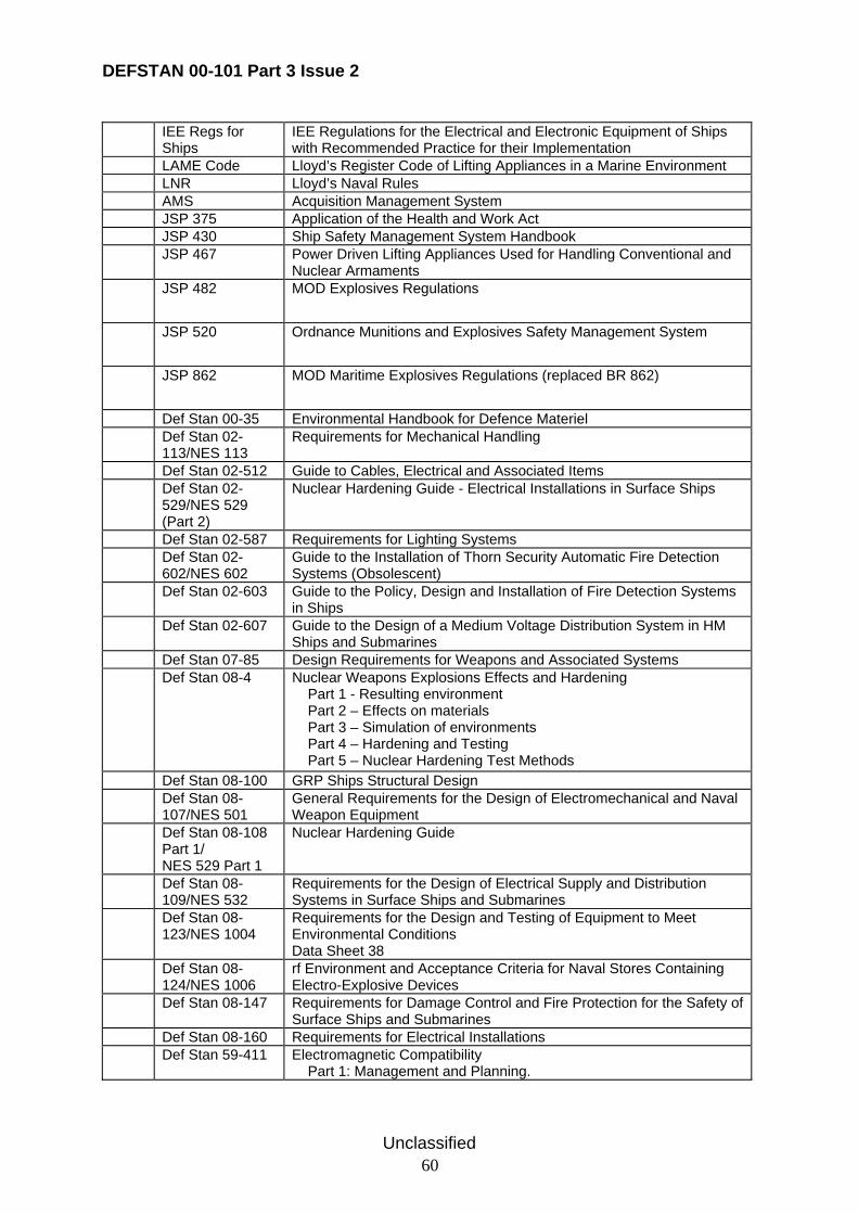
DEFSTAN 00-101 Part 3 Issue 2
Unclassified 60
IEE Regs for Ships
IEE Regulations for the Electrical and Electronic Equipment of Ships with Recommended Practice for their Implementation
LAME Code Lloyd’s Register Code of Lifting Appliances in a Marine Environment LNR Lloyd’s Naval Rules AMS Acquisition Management System JSP 375 Application of the Health and Work Act JSP 430 Ship Safety Management System Handbook JSP 467 Power Driven Lifting Appliances Used for Handling Conventional and
Nuclear Armaments JSP 482 MOD Explosives Regulations
JSP 520 Ordnance Munitions and Explosives Safety Management System
JSP 862 MOD Maritime Explosives Regulations (replaced BR 862)
Def Stan 00-35 Environmental Handbook for Defence Materiel Def Stan 02-
113/NES 113 Requirements for Mechanical Handling
Def Stan 02-512 Guide to Cables, Electrical and Associated Items Def Stan 02-
529/NES 529 (Part 2)
Nuclear Hardening Guide - Electrical Installations in Surface Ships
Def Stan 02-587 Requirements for Lighting Systems Def Stan 02-
602/NES 602 Guide to the Installation of Thorn Security Automatic Fire Detection Systems (Obsolescent)
Def Stan 02-603 Guide to the Policy, Design and Installation of Fire Detection Systems in Ships
Def Stan 02-607 Guide to the Design of a Medium Voltage Distribution System in HM Ships and Submarines
Def Stan 07-85 Design Requirements for Weapons and Associated Systems Def Stan 08-4 Nuclear Weapons Explosions Effects and Hardening
Part 1 - Resulting environment Part 2 – Effects on materials Part 3 – Simulation of environments Part 4 – Hardening and Testing Part 5 – Nuclear Hardening Test Methods
Def Stan 08-100 GRP Ships Structural Design Def Stan 08-
107/NES 501 General Requirements for the Design of Electromechanical and Naval Weapon Equipment
Def Stan 08-108 Part 1/ NES 529 Part 1
Nuclear Hardening Guide
Def Stan 08-109/NES 532
Requirements for the Design of Electrical Supply and Distribution Systems in Surface Ships and Submarines
Def Stan 08-123/NES 1004
Requirements for the Design and Testing of Equipment to Meet Environmental Conditions Data Sheet 38
Def Stan 08-124/NES 1006
rf Environment and Acceptance Criteria for Naval Stores Containing Electro-Explosive Devices
Def Stan 08-147 Requirements for Damage Control and Fire Protection for the Safety of Surface Ships and Submarines
Def Stan 08-160 Requirements for Electrical Installations Def Stan 59-411
Electromagnetic Compatibility Part 1: Management and Planning.
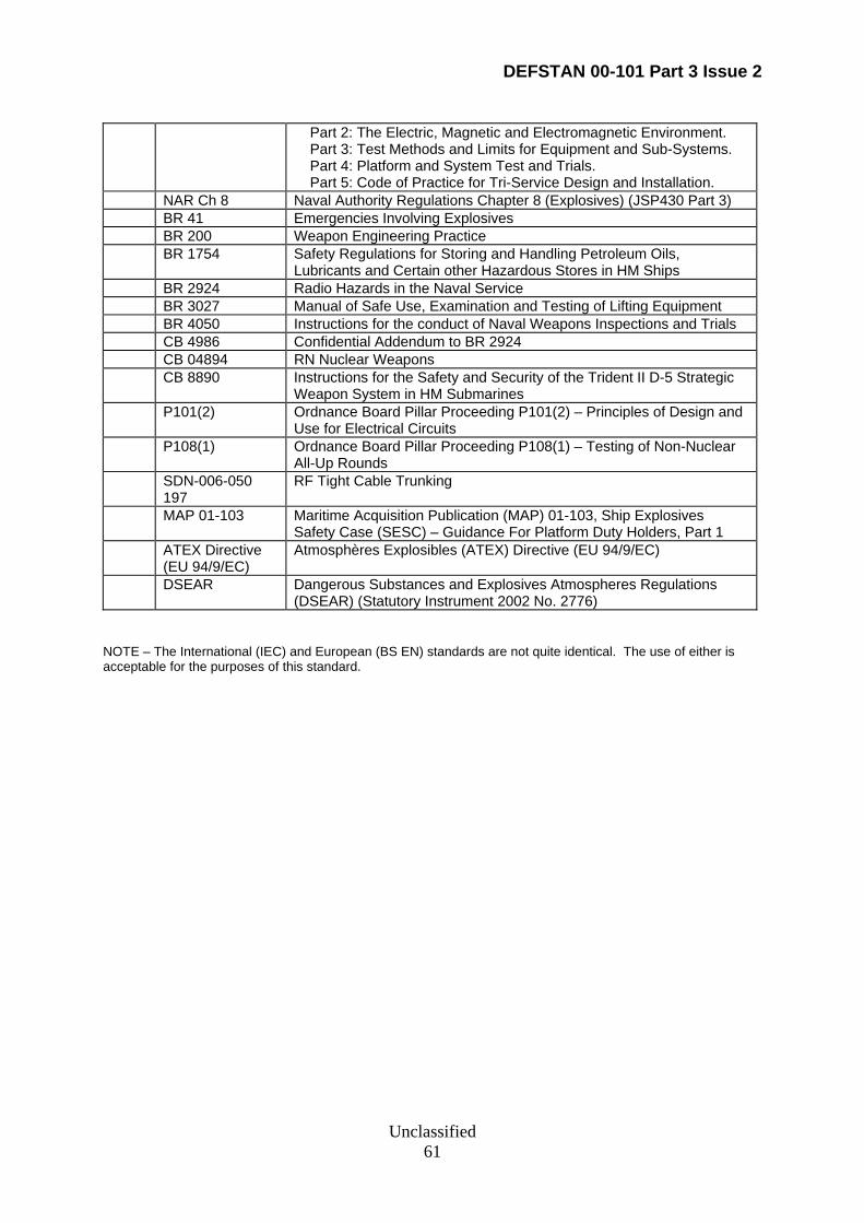
DEFSTAN 00-101 Part 3 Issue 2
Unclassified 61
Part 2: The Electric, Magnetic and Electromagnetic Environment. Part 3: Test Methods and Limits for Equipment and Sub-Systems. Part 4: Platform and System Test and Trials. Part 5: Code of Practice for Tri-Service Design and Installation.
NAR Ch 8 Naval Authority Regulations Chapter 8 (Explosives) (JSP430 Part 3) BR 41 Emergencies Involving Explosives BR 200 Weapon Engineering Practice BR 1754 Safety Regulations for Storing and Handling Petroleum Oils,
Lubricants and Certain other Hazardous Stores in HM Ships BR 2924 Radio Hazards in the Naval Service BR 3027 Manual of Safe Use, Examination and Testing of Lifting Equipment BR 4050 Instructions for the conduct of Naval Weapons Inspections and Trials CB 4986 Confidential Addendum to BR 2924 CB 04894 RN Nuclear Weapons CB 8890 Instructions for the Safety and Security of the Trident II D-5 Strategic
Weapon System in HM Submarines P101(2) Ordnance Board Pillar Proceeding P101(2) – Principles of Design and
Use for Electrical Circuits P108(1) Ordnance Board Pillar Proceeding P108(1) – Testing of Non-Nuclear
All-Up Rounds SDN-006-050
197 RF Tight Cable Trunking
MAP 01-103 Maritime Acquisition Publication (MAP) 01-103, Ship Explosives Safety Case (SESC) – Guidance For Platform Duty Holders, Part 1
ATEX Directive (EU 94/9/EC)
Atmosphères Explosibles (ATEX) Directive (EU 94/9/EC)
DSEAR Dangerous Substances and Explosives Atmospheres Regulations (DSEAR) (Statutory Instrument 2002 No. 2776)
NOTE – The International (IEC) and European (BS EN) standards are not quite identical. The use of either is acceptable for the purposes of this standard.
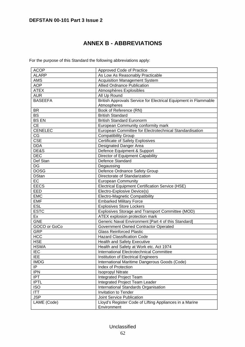
DEFSTAN 00-101 Part 3 Issue 2
Unclassified 62
ANNEX B - ABBREVIATIONS
For the purpose of this Standard the following abbreviations apply:
ACOP Approved Code of Practice ALARP As Low As Reasonably Practicable AMS Acquisition Management System AOP Allied Ordnance Publication ATEX Atmosphères Explosibles AUR All Up Round BASEEFA British Approvals Service for Electrical Equipment in Flammable
Atmospheres BR Book of Reference (RN) BS British Standard BS EN British Standard Euronorm CE European Community conformity mark CENELEC European Committee for Electrotechnical Standardisation CG Compatibility Group CSE Certificate of Safety Explosives DDA Designated Danger Area DE&S Defence Equipment & Support DEC Director of Equipment Capability Def Stan Defence Standard DG Degaussing DOSG Defence Ordnance Safety Group DStan Directorate of Standarization EC European Community EECS Electrical Equipment Certification Service (HSE) EED Electro-Explosive Device(s) EMC Electro-Magnetic Compatibility EMF Embarked Military Force ESL Explosives Store Lockers ESTC Explosives Storage and Transport Committee (MOD) Ex ATEX explosion protection mark GNE Generic Naval Environment [Part 4 of this Standard] GOCO or GoCo Government Owned Contractor Operated GRP Glass Reinforced Plastic HCC Hazard Classification Code HSE Health and Safety Executive HSWA Health and Safety at Work etc. Act 1974 IEC International Electrotechnical Committee IEE Institution of Electrical Engineers IMDG International Maritime Dangerous Goods (Code) IP Index of Protection IPN Isopropyl Nitrate IPT Integrated Project Team IPTL Integrated Project Team Leader ISO International Standards Organisation ITT Invitation to Tender JSP Joint Service Publication LAME (Code) Lloyd’s Register Code of Lifting Appliances in a Marine
Environment
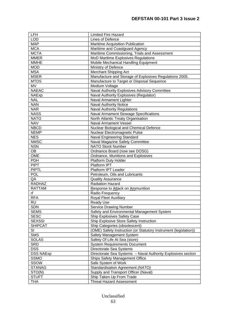
DEFSTAN 00-101 Part 3 Issue 2
Unclassified 63
LFH Limited Fire Hazard LOD Lines of Defence MAP Maritime Acquisition Publication MCA Maritime and Coastguard Agency MCTA Maritime Commissioning, Trials and Assessment MMER MoD Maritime Explosives Regulations MMHE Mobile Mechanical Handling Equipment MOD Ministry of Defence MSA Merchant Shipping Act MSER Manufacture and Storage of Explosives Regulations 2005. MTDS Manufacture to Target or Disposal Sequence MV Medium Voltage NAEAC Naval Authority Explosives Advisory Committee NAExp Naval Authority Explosives (Regulator) NAL Naval Armament Lighter NAN Naval Authority Notice NAR Naval Authority Regulations NASS Naval Armament Stowage Specifications NATO North Atlantic Treaty Organisation NAV Naval Armament Vessel NBCD Nuclear Biological and Chemical Defence NEMP Nuclear Electromagnetic Pulse NES Naval Engineering Standard NMSC Naval Magazine Safety Committee NSN NATO Stock Number OB Ordnance Board (now see DOSG) OME Ordnance, Munitions and Explosives PDH Platform Duty Holder PIPT Platform IPT PIPTL Platform IPT Leader POL Petroleum, Oils and Lubricants QA Quality Assurance RADHAZ Radiation Hazard RATTAM Response to Attack on Ammunition rf Radio Frequency RFA Royal Fleet Auxiliary RU Ready Use SDN Service Drawing Number SEMS Safety and Environmental Management System SESC Ship Explosives Safety Case SEXSSI Ship Explosive Store Safety Instruction SHIPCAT Ship Categories (obsolescent) SI (OME) Safety Instruction (or Statutory Instrument (legislation)) SMS Safety Management System SOLAS Safety Of Life At Sea (store) SRD System Requirements Document DSS Directorate Sea Systems DSS NAExp Directorate Sea Systems – Naval Authority Explosives section SSMO Ships Safety Management Office SSOW Safe System of Work STANAG Standardisation Agreement (NATO) STO(N) Supply and Transport Officer (Naval) STUFT Ship Taken Up From Trade THA Threat Hazard Assessment
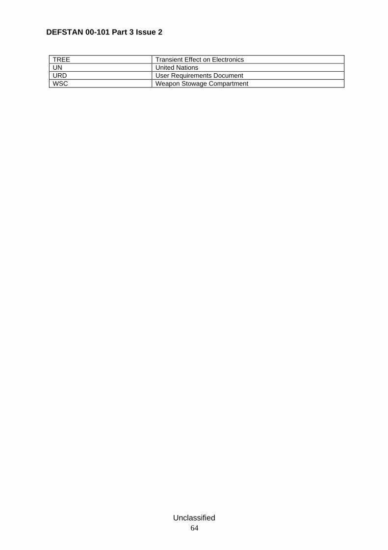
DEFSTAN 00-101 Part 3 Issue 2
Unclassified 64
TREE Transient Effect on Electronics UN United Nations URD User Requirements Document WSC Weapon Stowage Compartment
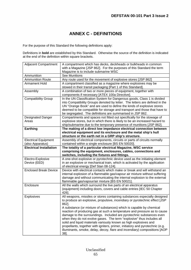
DEFSTAN 00-101 Part 3 Issue 2
Unclassified 65
ANNEX C - DEFINITIONS
For the purpose of this Standard the following definitions apply:
Definitions in bold are established by this Standard. Otherwise the source of the definition is indicated at the end of the definition within square brackets. Adjacent Compartment A compartment which has decks, deckheads or bulkheads in common
with a Magazine [JSP 862]. For the purposes of this Standard the term Magazine is to include submarine WSC
Ammunition See Munitions Ammunition Route Any route used for the movement of explosive stores [JSP 862] Armament Hold A compartment classified as a magazine where explosives may be
stowed in their transit packaging [Part 1 of this Standard]. Assembly A combination of two or more pieces of equipment, together with
components if necessary [ATEX 100a Directive]. Compatibility Group In the UN Classification System for Dangerous goods, Class 1 is divided
into Compatibility Groups denoted by letter. The letters are defined in the UN “Orange Book” and are used to define the kinds of explosive stores deemed to be compatible for storage and transport and those that have to be segregated. The definitions are summarised in JSP 862.
Designated Danger Areas
Compartments and spaces not fitted out specifically for the stowage of explosive stores, but in which there is likely to be an increased hazard to ship/submarine due to the temporary presence of munitions [JSP 862].
Earthing The making of a direct low impedance electrical connection between electrical equipment and its enclosure and the metal ship’s hull structure or the earth net in a GRP ship’s structure.
Electrical Equipment (also Apparatus)
Assembly of electrical components, circuits or parts of circuits normally contained within a single enclosure [BS EN 50020].
Electrical Installation The totality of a particular electrical Magazine, WSC service comprising the equipment, enclosures, cables, connections and switches, including the fixtures and fittings.
Electro-Explosive Device (EED)
A one-shot explosive or pyrotechnic device used as the initiating element in an explosive or mechanical train, which is activated by the application of electrical energy [Def Stan 08-124].
Enclosed Break Device Device with electrical contacts which make or break and will withstand an internal explosion of a flammable gas/vapour air mixture without suffering damage and without communicating the internal explosion to the external flammable gas/vapour/air mixture [BS EN 50021].
Enclosure All the walls which surround the live parts of an electrical apparatus (equipment) including doors, covers and cable entries [IEC 50 Chapter 426].
Explosives All weapons, missiles or stores containing substances especially designed to produce an explosive, propulsive, incendiary or pyrotechnic effect [JSP 862]. A substance (or mixture of substances) which is capable by chemical reaction of producing gas at such a temperature and pressure as to cause damage to the surroundings. Included are pyrotechnic substances even when they do not evolve gases. The term “explosive” thus includes all solid and liquid materials variously known as high explosives and propellants, together with igniters, primer, initiatory and pyrotechnic (e.g. illuminants, smoke, delay, decoy, flare and incendiary) compositions [AOP 38].
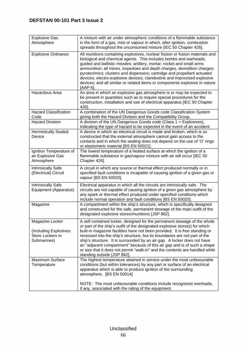
DEFSTAN 00-101 Part 3 Issue 2
Unclassified 66
Explosive Gas Atmosphere
A mixture with air under atmospheric conditions of a flammable substance in the form of a gas, mist or vapour in which, after ignition, combustion spreads throughout the unconsumed mixture [IEC 50 Chapter 426].
Explosive Ordnance All munitions containing explosives, nuclear fission or fusion materials and biological and chemical agents. This includes bombs and warheads; guided and ballistic missiles; artillery, mortar, rocket and small arms ammunition; all mines, torpedoes and depth charges, demolition charges; pyrotechnics; clusters and dispensers; cartridge and propellant actuated devices; electro-explosive devices; clandestine and improvised explosive devices; and all similar or related items or components explosive in nature [AAP-6].
Hazardous Area An area in which an explosive gas atmosphere is or may be expected to be present in quantities such as to require special procedures for the construction, installation and use of electrical apparatus [IEC 50 Chapter 426].
Hazard Classification Code
A combination of the UN Dangerous Goods code Classification System giving both the Hazard Division and the Compatibility Group.
Hazard Division A division of the UN Dangerous Goods code (Class 1 = Explosives), indicating the type of hazard to be expected in the event of an accident.
Hermetically Sealed Device
A device in which an electrical circuit is made and broken, which is so constructed that the external atmosphere cannot gain access to the contacts and in which the sealing does not depend on the use of ‘O’ rings or elastomeric material [BS EN 50021].
Ignition Temperature of an Explosive Gas Atmosphere
The lowest temperature of a heated surface at which the ignition of a flammable substance in gas/vapour mixture with air will occur [IEC 50 Chapter 426].
Intrinsically Safe (Electrical) Circuit
A circuit in which any source or thermal effect produced normally or in specified fault conditions is incapable of causing ignition of a given gas or vapour [BS EN 50020].
Intrinsically Safe Equipment (Apparatus)
Electrical apparatus in which all the circuits are intrinsically safe. The circuits are not capable of causing ignition of a given gas atmosphere by any spark or thermal effect produced under specified conditions which include normal operation and fault conditions [BS EN 50020].
Magazine A compartment within the ship’s structure, which is specifically designed and constructed for the safe, permanent stowage of the main outfit of the designated explosive stores/munitions [JSP 862].
Magazine Locker (Including Explosives Store Lockers in Submarines)
A self contained locker, designed for the permanent stowage of the whole or part of the ship’s outfit of the designated explosive store(s) for which built-in magazine facilities have not been provided. It is free standing or recessed into the ship’s structure, but its boundaries are not part of the ship’s structure. It is surrounded by an air gap. A locker does not have an “adjacent compartment” because of this air gap and is of such a shape or size that it does not permit “walk-in” and the contents are handled while standing outside [JSP 862].
Maximum Surface Temperature
The highest temperature attained in service under the most unfavourable conditions (but within tolerances) by any part or surface of an electrical apparatus which is able to produce ignition of the surrounding atmosphere. [BS EN 50014] NOTE: The most unfavourable conditions include recognized overloads, if any, associated with the rating of the equipment.
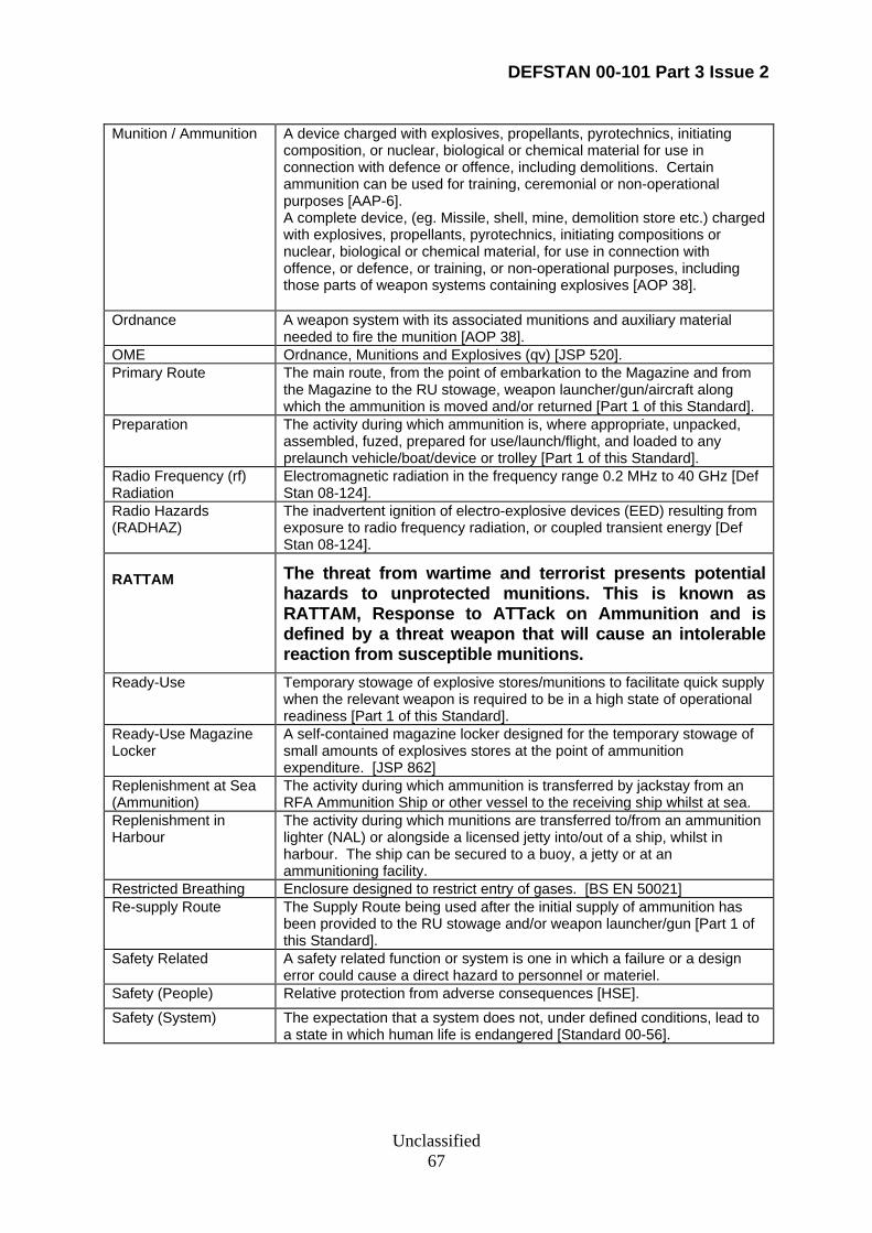
DEFSTAN 00-101 Part 3 Issue 2
Unclassified 67
Munition / Ammunition A device charged with explosives, propellants, pyrotechnics, initiating composition, or nuclear, biological or chemical material for use in connection with defence or offence, including demolitions. Certain ammunition can be used for training, ceremonial or non-operational purposes [AAP-6]. A complete device, (eg. Missile, shell, mine, demolition store etc.) charged with explosives, propellants, pyrotechnics, initiating compositions or nuclear, biological or chemical material, for use in connection with offence, or defence, or training, or non-operational purposes, including those parts of weapon systems containing explosives [AOP 38].
Ordnance A weapon system with its associated munitions and auxiliary material needed to fire the munition [AOP 38].
OME Ordnance, Munitions and Explosives (qv) [JSP 520]. Primary Route The main route, from the point of embarkation to the Magazine and from
the Magazine to the RU stowage, weapon launcher/gun/aircraft along which the ammunition is moved and/or returned [Part 1 of this Standard].
Preparation The activity during which ammunition is, where appropriate, unpacked, assembled, fuzed, prepared for use/launch/flight, and loaded to any prelaunch vehicle/boat/device or trolley [Part 1 of this Standard].
Radio Frequency (rf) Radiation
Electromagnetic radiation in the frequency range 0.2 MHz to 40 GHz [Def Stan 08-124].
Radio Hazards (RADHAZ)
The inadvertent ignition of electro-explosive devices (EED) resulting from exposure to radio frequency radiation, or coupled transient energy [Def Stan 08-124].
RATTAM
The threat from wartime and terrorist presents potential hazards to unprotected munitions. This is known as RATTAM, Response to ATTack on Ammunition and is defined by a threat weapon that will cause an intolerable reaction from susceptible munitions.
Ready-Use Temporary stowage of explosive stores/munitions to facilitate quick supply when the relevant weapon is required to be in a high state of operational readiness [Part 1 of this Standard].
Ready-Use Magazine Locker
A self-contained magazine locker designed for the temporary stowage of small amounts of explosives stores at the point of ammunition expenditure. [JSP 862]
Replenishment at Sea (Ammunition)
The activity during which ammunition is transferred by jackstay from an RFA Ammunition Ship or other vessel to the receiving ship whilst at sea.
Replenishment in Harbour
The activity during which munitions are transferred to/from an ammunition lighter (NAL) or alongside a licensed jetty into/out of a ship, whilst in harbour. The ship can be secured to a buoy, a jetty or at an ammunitioning facility.
Restricted Breathing Enclosure designed to restrict entry of gases. [BS EN 50021] Re-supply Route The Supply Route being used after the initial supply of ammunition has
been provided to the RU stowage and/or weapon launcher/gun [Part 1 of this Standard].
Safety Related A safety related function or system is one in which a failure or a design error could cause a direct hazard to personnel or materiel.
Safety (People) Relative protection from adverse consequences [HSE]. Safety (System) The expectation that a system does not, under defined conditions, lead to
a state in which human life is endangered [Standard 00-56].
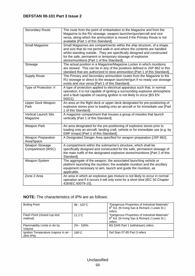
DEFSTAN 00-101 Part 3 Issue 2
Unclassified 68
Secondary Route The route from the point of embarkation to the Magazine and from the Magazine to the RU stowage, weapon launcher/gun/aircraft and vice versa, along which the ammunition is moved if the Primary Route is not available [Part 1 of this Standard].
Small Magazine Small Magazines are compartments within the ship structure, of a shape and size that do not permit walk-in and where the contents are handled whilst standing outside. They are specifically designed and constructed for the safe, permanent or temporary stowage of explosive stores/munitions [Part 1 of this Standard].
Stowage The actual position in a Magazine/Magazine Locker in which munitions are stowed. This can be in any of the positions defined in JSP 862 or this standard that are authorized to stow ammunition [Part 1 of this Standard].
Supply Route The Primary and Secondary ammunition routes from the Magazine to the RU stowage or direct to the weapon launcher/gun if no ready use stowage exists and vice versa [Part 1 of this Standard].
Type of Protection ‘n’ A type of protection applied to electrical apparatus such that, in normal operation, it is not capable of igniting a surrounding explosive atmosphere and a fault capable of causing ignition is not likely to occur [BS EN 50021].
Upper Deck Weapon Park
An area on the flight deck or upper deck designated for pre-positioning of explosive stores prior to loading onto an aircraft or for immediate use [Part 1 of this Standard].
Vertical Launch Silo Magazine
A magazine compartment that houses a group of missiles that launch vertically [Part 1 of this Standard].
Weapon Park An area designated for the pre-positioning of explosive stores prior to loading onto an aircraft, landing craft, vehicle or for immediate use (e.g. by EMF troops) [Part 1 of this Standard].
Weapon Preparation Area/Space
A Designated Danger Area specified for weapon preparation [JSP 862].
Weapon Stowage Compartment (WSC)
A compartment within the submarine’s structure, which shall be specifically designed and constructed for the safe, permanent stowage of the main outfit of the designated explosive stores/munitions [Part 2 of this Standard].
Weapon System The aggregate of the weapon, the associated launching vehicle or platform launching the munition, the available munition and the ancillary equipment necessary to aim, launch and guide the munition, as applicable.
Zone 2 Area An area in which an explosive gas mixture is not likely to occur in normal operation and if it occurs it will only exist for a short time [IEC 50 Chapter 426/IEC 60079-10].
NOTE: The characteristics of IPN are as follows: Boiling Point 98 - 102°C “Dangerous Properties of Industrial Materials”
8th Ed. (N Irving Sax & Richard J Lewis Sr.) refers.
Flash Point (closed cup test method)
11.1°C “Dangerous Properties of Industrial Materials” 8th Ed. (N Irving Sax & Richard J Lewis Sr.) refers.
Flammability Limits in Air by Volume
2% - 100% BS 5345 Part 1 (withdrawn) refers.
Ignition Temperature (vapour in air - 28% IPN)
190°C Def Stan 07-85 Part 3 refers
© Crown Copyright 2008
Copying Only as Agreed with DStan
Defence Standards are Published by and Obtainable from:
Defence Procurement Agency An Executive Agency of The Ministry of Defence
UK Defence Standardization Kentigern House 65 Brown Street
GLASGOW G2 8EX
DStan Helpdesk
Tel 0141 224 2531/2 Fax 0141 224 2503
Internet e-mail [email protected]
File Reference The DStan file reference relating to work on this standard is D/DStan21/101/3. Contract Requirements When Defence Standards are incorporated into contracts users are responsible for their correct application and for complying with contractual and statutory requirements. Compliance with a Defence Standard does not in itself confer immunity from legal obligations. Revision of Defence Standards Defence Standards are revised as necessary by up issue or amendment. It is important that users of Defence Standards should ascertain that they are in possession of the latest issue or amendment. Information on all Defence Standards is contained in Def Stan 00-00 Standards for Defence Part 3 , Index of Standards for Defence Procurement Section 4 ‘Index of Defence Standards and Defence Specifications’ published annually and supplemented regularly by Standards in Defence News (SID News). Any person who, when making use of a Defence Standard encounters an inaccuracy or ambiguity is requested to notify the Directorate of Standardization (DStan) without delay in order that the matter may be investigated and appropriate action taken.