military handbook interface control document...
TRANSCRIPT
MIL-HDBK-258(AS)
3 August 1979
MILITARY HANDBOOK
INTERFACE CONTROL DOCUMENT
INFRAR EDAN
FORDETECTING SET/AAS-36
FSC 5855
Downloaded from http://www.everyspec.com
MIL-HDBK-258(AS)
DEPARTMENT OF DEFENSEWASHINGTON, D C 20360
MIL-HDBK-258(AS)Interface Control Document for Infrared Detecting Set AN/AAS-36
1. This interface control handbook was developed by the Departmentof Defense with the assistance of the Naval Air Systems Command inaccordance with established procedure.
2. This document was approved on for printing andinclusion in the military interface control handbook series.
3. This document provides basic and fundamental information on thephysical and functional interface requirements for aircraft installa-tion of the AN/AAS-36 Infrared Detecting Set. The defined interfacesestablish the compatibility between cofunctioning elements and controlthe interface design. This handbook is intended to be referenced inpurchase specifications for applicable equipment.
4. Every effort has been made to reflect the latest information oninstallation interface requirements for the AN/AAS-36 Infrared Detect-ing Set. It is the intent to review this handbook periodically toinsure its completeness and currency. Beneficial comments (recommen-dations, additions,. deletions) and any pertinent data which q ay be ofuse in improving this document, should be addressed to: CommandingOfficer, Naval Air Engineering Center, Engineering Specifications andStandards Department (ESSD) Code 93, Lakehurst, NJ 08733, by using theself-addressed Standardization Document Improvement Proposal (DD Form1426) appearing at the end of this document or by letter.
ii
I
Downloaded from http://www.everyspec.com
MIL-HDBK-258(AS)
CONTENTS
Page
Paragraph 1.1.11.21.31.3.1
2.2.12.2
3.3.1
4.4.14.1.14.1.24.1.34.1.44.1.54.1.64.24.34.3.14.3.1.14.3.1.24.3.1.34.3.1.44.3.24.3.2.14.3.2.24.3.2.34.3.2.44.3.34.3.3.14.3.3.24.3.3.34.3.3.44.3.44.3.4.14.3.4.24.3.4.34.3.4.4
S C O P E - - - - - - - - - - - - - - - - - - - -S c o p e - - - - - - - - - - - - - - - - - - -P u r p o s e - - - - - - - - - - - - - - - - - -General conditions and responsibilities- - -Associated equipment- - - - - - - - - - - -
REFERENCED DOCUMENTS - - - - - - - - - - - -Issues of documents------------Non-Government documents- - - - - - - - - -
D E F I N I T I O N S - - - - - - - - - - - - - - - - -Symbols, abbreviations and acronyms - - - -
GENERAL STATEMENT OF REQUIREMENTS- - - - - -Functional description- - - - - - - - - - -Receiver converter- - - - - - - - - - - - -Power supply/video converter- - - - - - - -Control, servomechanism - - - - - - - - - -Control, detecting set, infrared- - - - - -Control, sight, target tracking - - - - - -Indicator, video--------------Overall characteristics - - - - - - - - - -Aircraft installation - - - - - - - - - - -Receiver converter- - - - - - - - - - - - -Location of unit--------------Limits to normal operation attitude - - - -P r e c a u t i o n s - - - - - - - - - - - - - - - -Mounting instructions - - - - - - - - - - -Power supply-video converter- - - - - - - -Location of unit--------------Limits to normal operation attitude - - - -P r e c a u t i o n s - - - - - - - - - - - - - - - -Mounting instructions - - - - - - - - - - -Control-servomechanism- - - - - - - - - - -Location of unit--------------Limits to normal operation attitude - - - -Precautions- - - - - - -- - - - - - - - -Mounting instructions - - - - - - - - - - -Control, detecting set, infrared- - - - - -Location of unit--------------Limits to normal operation attitude - - - -P r e c a u t i o n s - - - - - - - - - - - - - - - -Mounting instructions - - - - - - - - - - -
11111
223
55
666777788888899999
101010101010111111111111
iii
Downloaded from http://www.everyspec.com
MIL-HDBK-258(AS)
CONTENTS - Continued
Page
Paragraph 4.3.4.54.3.54.3.5.14.3.5.24.3.5.34.3.5.44.3.5.54.3.64.3.6.14.3.6.24.3.6.34.3.6.44.3.6.5
Environmental limits- - - - - - - - - - - - 11Control, sight, target tracking - - - - - - 11Location of unit--------------11Limits to normal operation attitude - - - - 12P r e c a u t i o n s - - - - - - - - - - - - - - - - 1 2Mounting instructions - - - - - - - - - - - 12Environmental limits- - - - - - - - - - - - 12Indicator, video- - - - - - - - - - - - - - 12Location of unit----- --------- 12Limits to normal operation attitude - - - - 12P r e c a u t i o n s - - - - - - - - - - - - - - - 1 2Mounting instructions - - - - - - - - - - - 13Environmental limits- - - - - - - - - - - - 13
5. DETAILED STATEMENT OF REQUIREMENTS - - - - - 14501 AN/AAS-36 (IRDS)/aircraft interfaces- - - - 145.1.1 M e c h a n i c a l - - - - - - - - - - - - - - - - - 1 45.1.1.1 WRA (outline dimension drawings)- - - - - - 145.1.2 Aircraft installation retractable turret
( t y p i c a l ) - - - - - - - - - - - - - - - - - - 1 45.1.3 Aircraft installation fixed turret
( t y p i c a l ) - - - - - - - - - - - - - - - - - 1 45.1.4 Thermal characteristic requirements - - - - 145.1.5 Receiver converter aircraft alignment
accuracy requirement - - - - - - - - - - - 145.1.6 Receiver-converter assembly - mechanical
alignment check - retractable turret - - - 155.1.7 Receiver-converter assembly - mechanical
alignment check - fixed turret - - - - - - 155.2 E l e c t r i c a l - - - - - - - - - - - - - - - - - 1 55.2.1 Aircraft power ---------------155.2.1.1 Aircraft power characteristics- - - - - - - 155.2.2 Equipment power requirements- - - - - - - - 165.2.2,1 AN/AAS-36 input power - - - - - - - - - - - 165.2.2.2 AN/AAS-36 input power requirements- - - - - 165.2.2.3 IRDS/aircraft electrical system interface - 175.2.2.3.1 IRDS aircraft electrical system interface - 175.2.2.3.2 IRDS/lamp test power source interface - - - 175.2.3 Interconnection diagrams- - - - - - - - - - 175.2.4 Cabling details -------------- 175.2.5 Ground/bonding- - - - - - - - - - - - - - - 175.2.5.1 Aircraft interconnecting cables - - - - - 185.2.6 Video characteristics - - - - - - - - - - - 18
iv
Downloaded from http://www.everyspec.com
MIL-HDBK-258(AS)
Page
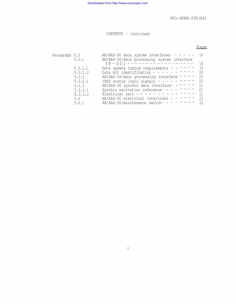
Paragraph 5.35.3.1
5.3.1.15.3.1.25.3.25.3.2.15.3.35.3.3.15.3.3.25.45.4.1
CONTENTS - Continued
AN/AAS-36 data system interfaces- - - - - -AN/AAS-36/data processing system interface( P - 3 C ) - - - - - - - - - - - - - - - - - -
Data update timing requirements - -Data bit identification - - - - - -AN/AAS-36/data processing interfaceIRDS status logic signals - - - - -AN/AAS-36 synchro data interface- -Synchro excitation reference- - - -Electrical zero - - - - - - - - - -AN/AAS-36 electrical interlocks - -AN/AAS-36/maintenance switch- - - -
- - - -- - - -- - - -- - - -- - - -- - - -- - - -- - - -- - - -
18
18192020202121212222
v
Downloaded from http://www.everyspec.com
MIL-HDBK-258 (AS)
FIGURES
Page
Figure 12
34
5
67
8
91011
1213
1415161718
1920212223
24
2526
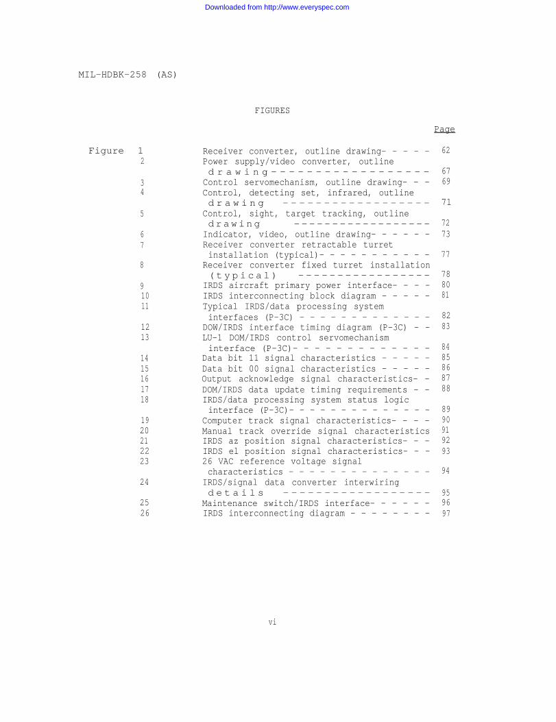
Receiver converter, outline drawing- - - - -Power supply/video converter, outlined r a w i n g - - - - - - - - - - - - - - - - - -
Control servomechanism, outline drawing- - -Control, detecting set, infrared, outlined r a w i n g - - - - - - - - - - - - - - - - - -
Control, sight, target tracking, outlined r awing ------------------
Indicator, video, outline drawing- - - - - -Receiver converter retractable turretinstallation (typical)- - - - - - - - - - -
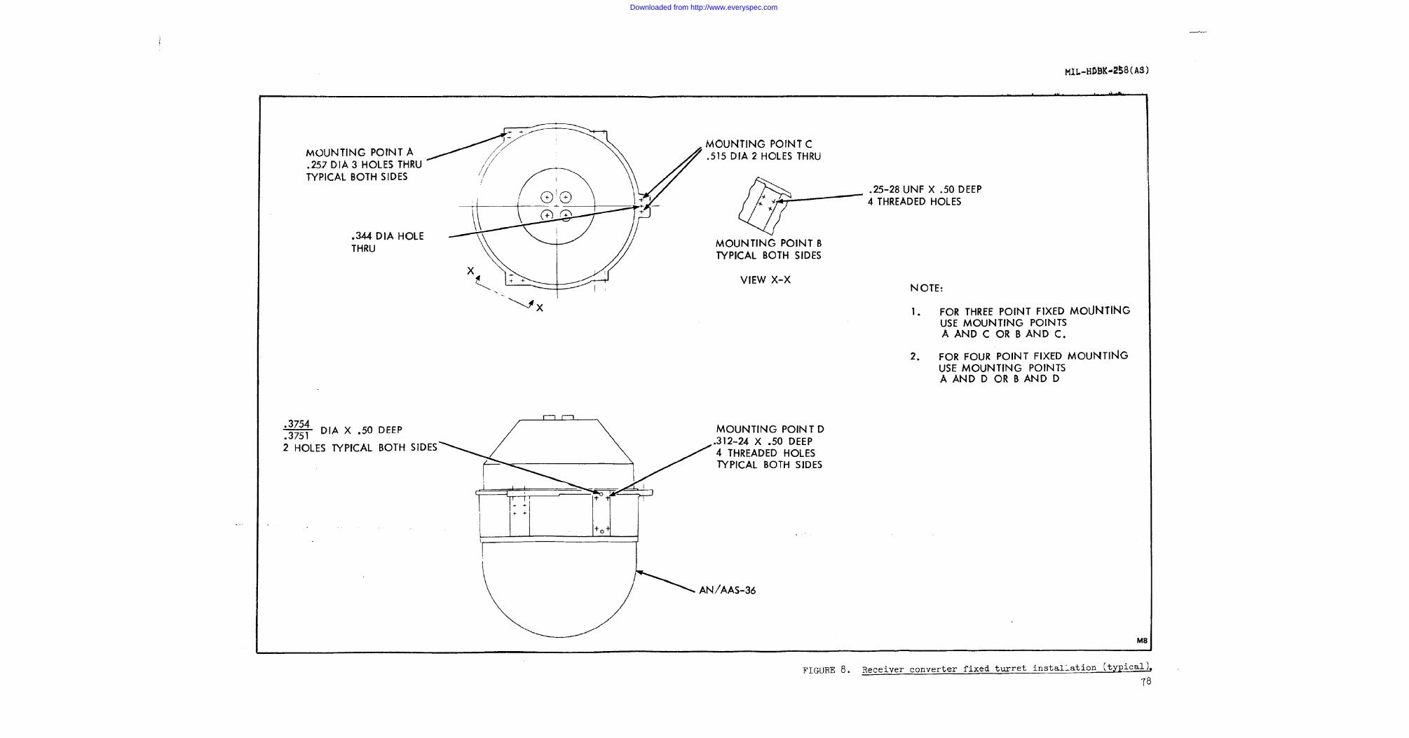
Receiver converter fixed turret installation( t y p i c a l ) - - - - - - - - - - - - - - - - -
IRDS aircraft primary power interface- - - -IRDS interconnecting block diagram - - - - -Typical IRDS/data processing systeminterfaces (P-3C) - - - - - - - - - - - - -
DOW/IRDS interface timing diagram (P-3C) - -LU-1 DOM/IRDS control servomechanisminterface (P-3C)- - - - - - - - - - - - -
Data bit 11 signal characteristics - - - - -Data bit 00 signal characteristics - - - - -Output acknowledge signal characteristics- -DOM/IRDS data update timing requirements - -IRDS/data processing system status logicinterface (P-3C)- - - - - - - - - - - - - -
Computer track signal characteristics- - - -Manual track override signal characteristicsIRDS az position signal characteristics- - -IRDS el position signal characteristics- - -26 VAC reference voltage signalcharacteristics - - - - - - - - - - - - - -
IRDS/signal data converter interwiringd e t a i l s - - - - - - - - - - - - - - - - - -
Maintenance switch/IRDS interface- - - - - -IRDS interconnecting diagram - - - - - - - -
62
6769
71
7273
77
788081
8283
8485868788
8990919293
94
959697
vi
Downloaded from http://www.everyspec.com
TABLES
Page
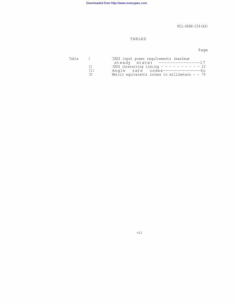
Table I
IIIIIIV
MIL-HDBK-258(AS)
IRDS input power requirements (maximumsteady state) ---------------17
IRDS interwiring listing - - - - - - - - - - 23Angle rate codes--------------6oMetric equivalents inches to millimeters - - 79
vii
Downloaded from http://www.everyspec.com

Downloaded from http://www.everyspec.com
MIL-HDBK-258(AS)
1. SCOPE
1.1 Scope. This handbook establishes the physical and functionalinterface for aircraft installation of the AN/AAS-36 infrared detectingset (IRDS). The physical and electrical interfaces are defined for theIRDS supplier, the airframe contractor and the operational program.
1.2 Purpose. The defined interfaces establish the compatibilitybetween cofunctioning elements and control the interface design. Anychanges in these areas may affect the installation compatibility oroperation. Contemplated changes affecting any of the defined area mustbe coordinated with all custodial and review activities.
1.3 General conditions responsibilities. The AN/AAS-36 IRDS wasdesigned and is fabricated by Texas Instruments. Intended airborne in-stallation of the IRDS is for either retractable or fixed turret appli-cations for such aircraft as P-3B, P-3C, S-3A, etc. Target tracking bythe IRDS is either manual or computer controlled, via on-board dataprocessing systems, when applicable. Lockheed Aircraft Companydesigned and fabricates a turret retraction mechanism for P-3C IRDSinstallations. NADC developed the necessary software programs to con-trol IRDS tracking for this configuration.
1.3.1 Associated equipment. The AN/AAS-36 interfaces with data pro-cessing systems such as the AN/AYA-8 [MIL-D-81347C(AS)] andAN/ASQ-l14(V) [MIL-C-81332B(AS)], a synchro to digital converter suchas the CV-2461 A/A [MIL-C-81344(AS)], aircraft power and lighting sup-plies and aircraft maintenance control devices.
1
Downloaded from http://www.everyspec.com
MIL-HDBK-258(AS)
2. REFERENCED DOCUMENTS
2.1 Issues of documents. The following documents of the exact issueindicated, form a part of this handbook to the extent specified herein.
SPECIFICATIONS
MILITARY
MIL-C-172C
MIL-C-81332B(AS)1 May 1967
MIL-C-81344(AS)1 May 1968
MIL-D-81347C(AS)13 March 1974
NAVAL AIR SYSTEMS COMMAND
MIL-I-85295(AS)15 April 1979
BUREAU OF NAVAL WEAPONS
WR-101, Part Idated (15 Feb 1968)
- Cases, Bases, Mounting;Mounts, Vibration.
- Military Specificationfor Computer, DigitalAN/ASQ-l14(V).
- Military Specificationfor Signal Data Con-verter CV-2461A/A.
- Military Specificationfor Data Analysis Pro-gramming GroupAN/AYA-8.
- Military Specification- Detecting Set, Infra-
red AN/AAS-36.
- Electromagnetic ControlRequirements for Ad-vanced ASW AvionicsSystem.
2
Downloaded from http://www.everyspec.com
MIL-HDBK-258(AS)
STANDARDS
MILITARY
MIL-STD-704A9 August 1966
MIL-STD-1472B31 December 1974
- Military Standard -Electric Power, Air-craft, Characteristicsand Utilization.
- Human Engineering De-sign Criteria forMilitary Systems Engi-neering and Facilities.
DRAWINGS
MILITARY
MS25213 - Control Panel, AircraftEquipment, TypicalInstallations.
(Copies of specifications, standards, drawings and publications re-quired by contractors in connection with specific procurement functionsshould be obtained from the procuring activity or as directed by thecontracting officer.)
2.2 Non-Government publications. The following documents of theexact issue date indicated, form a part of this handbook to the extentspecified herein.
ELECTRONIC INDUSTRIES ASSOCIATES
EIA-RS-343-ASeptember 1969
GENERAL ELECTRIC COMPANY
G.E. 7528383
G.E. 7528376
- Electrical PerformanceStandard for High Reso-lution MonochromeClosed Circuit Televi-sion Camera.
- Device Specification -Line Receiver.
- Device Specification -Line Driver.
3
Downloaded from http://www.everyspec.com
MIL-HDBK-258(AS)
TEXAS INSTRUMENTS
T.I. 536993
T.I. 536996-1
Device Specification -Line Receiver (Equiva-lent to National -DM7820).
Device Specification -Line Driver (Equivalentto National DM7830).
Application for copies of non-government documents should beaddressed to the Naval Air Systems Command, Washington, D C 20360,Attn: AIR-549332.
4
Downloaded from http://www.everyspec.com
MIL-HDBK-258(AS)
3. DEFINITIONS
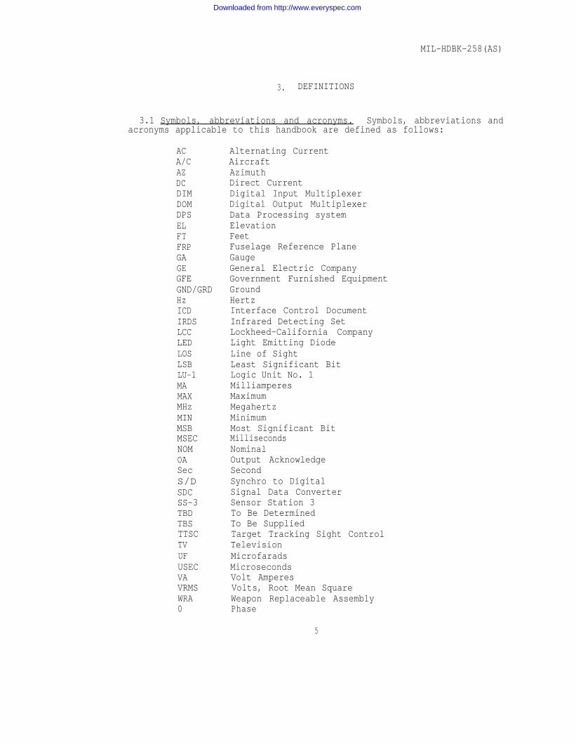
3.1 Symbols, abbreviations and acronyms. Symbols, abbreviations andacronyms applicable to this handbook are defined as follows:
ACA/CAZDCDIMDOMDPSELFTFRPGAGEGFEGND/GRDHzICDIRDSLCCLEDLOSLSBLU-1MAMAXMHzMINMSBMSECNOMOASecS/DSDCSS-3TBDTBSTTSCTVUFUSECVAVRMSWRA0
Alternating CurrentAircraftAzimuthDirect CurrentDigital Input MultiplexerDigital Output MultiplexerData Processing systemElevationFeetFuselage Reference PlaneGaugeGeneral Electric CompanyGovernment Furnished EquipmentGroundHertzInterface Control DocumentInfrared Detecting SetLockheed-California CompanyLight Emitting DiodeLine of SightLeast Significant BitLogic Unit No. 1MilliamperesMaximumMegahertzMinimumMost Significant BitMillisecondsNominalOutput AcknowledgeSecondSynchro to DigitalSignal Data ConverterSensor Station 3To Be DeterminedTo Be SuppliedTarget Tracking Sight ControlTelevisionMicrofaradsMicrosecondsVolt AmperesVolts, Root Mean SquareWeapon Replaceable AssemblyPhase
5
Downloaded from http://www.everyspec.com
MIL-HDBK-258(AS)
4. GENERAL STATEMENT OF REQUIREMENTS
4.1 Functional description. Infrared Detecting Set AN/AAS-36 is amodularized IR sensor system composed of the following six WRA’s:
Receiver Converter, Infrared R-2005/AAS-36Power Supply/Video Converter PP-7267/AAS-36Control Servomechanism C-9982/AAS-36Control, Detecting Set, IR C-9983/AAS-36Control, Sight, Target Tracking C-9984/AAS-36Indicator Video IP-1240/AAS-36
The receiver converter is installed in a fixed or retractable turret,preferably on the underside of the aircraft fuselage. Sensor operationis controlled by on-board operators by means of the control, sight, tar-get tracking (hand control) in manual mode and by data processingsystem interfaces in computer track mode. In the computer track mode,the data processing system accepts IRDS gimbal position data, computesthe angular difference between the LOS to the target and the platformboresight reference axis and provides azimuth and elevation ratecommands to reposition the gimbals.
4.1.1 Receiver converter. The receiver converter contains the IRsensing unit mounted on a two-axis gimbal system. The outer turrethousing rotates ±200° from the FRP(YZ) of the aircraft with the azimuthgimbal. The elevation gimbals are not subjected to airloads, operatingcompletely inside the turret housing within +16 and -820 limits refer-enced to the FRP(YZ).
The sensor has a two-position lens system providing two fields ofview, 250 (diagonal) and approximately 80 (diagonal), selectable by theoperator. Cooling for the detector elements is provided by a self-con-tained closed-cycle, cryogenic cooler. The individual IR image chan-nels are amplified and operate a companion LED channel. These elementsare converted to standard EIA imagery by mirror-sweeping these channelsover a vidicon tube. Standard TV signal processing provides the imageon the TV display.
The receiver converter is designed to operate satisfactorily over anambient temperature range of -54°C to +55°C. At ambient temperaturesbelow +20°C, the unit maintains an internal temperature of approxi-mately +25°C by automatically-controlled heater elements. At ambienttemperatures above +25°C and up to a maximum steady state temperatureOf +55°C, the receiver converter utilizes external ambient air and anair to air heat exchanger to maintain proper internal receiver-converter operating temperatures.
6
Downloaded from http://www.everyspec.com
MIL-HDBK-258(AS)
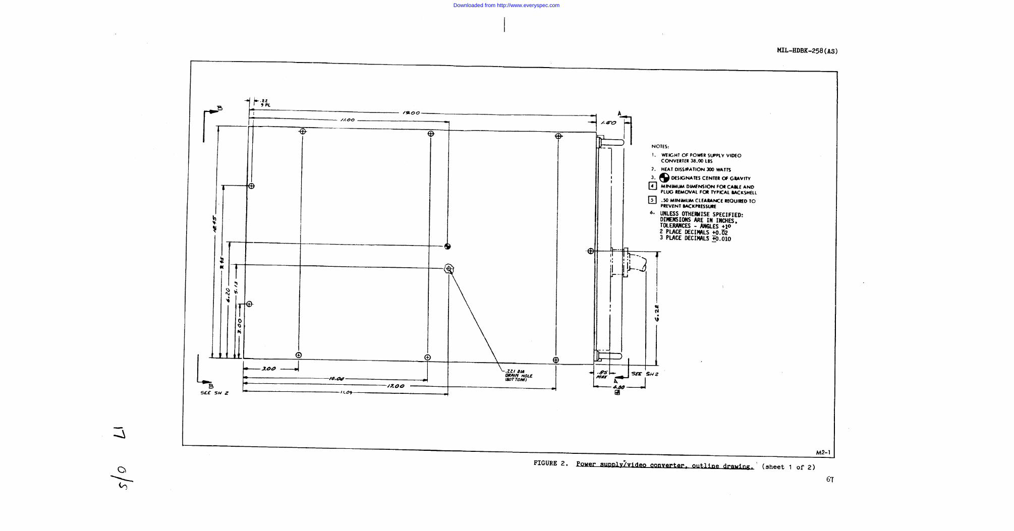
Because the receiver converter weight exceeds the lift capability ofone or even two men as defined in MIL-STD-1472B, this WRA is providedwith lift points for removal/replacement in the aircraft.
4.1.2 Power supply/video converter. This unit provides the inter-face between the aircraft 28 VDC and 115/200 V 400 Hz aircraft powersources and the IRDS system. The power supply provides ±14 and ±15 VDCfor the sensor focus; ±5, ±8, +10, ±15 VDC for sensor preamp, post ampsand scanner circuits; +5, ±8.5, +40 VDC for TV circuits; and ±15 VDCfor the gimbal angle indicator circuitry. Video signals from thereceiver converter are combined with gimbal angle signals for presenta-tion on the video indicator. The grey scale generator for settingvideo indicator controls is also located in this unit.
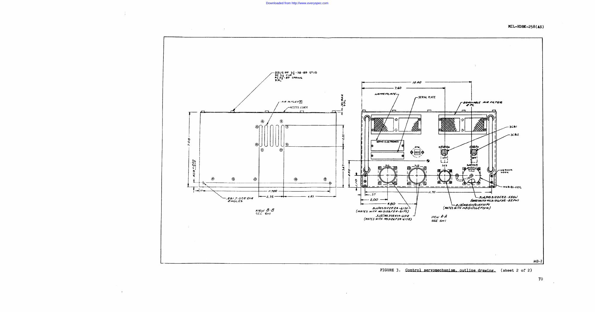
4.1.3 Control servomechanism. The unit accepts data processingsystem generated rate signals or target tracking position inputs togenerate proper azimuth and elevation rate drive signals to positionthe receiver converter. Receiver-converter azimuth and elevationposition feedback to the data processing system is provided for posi-tion compensation. Four power supplies provide ±30, ±15, and +5 VDCfor servo and turret drive functions.
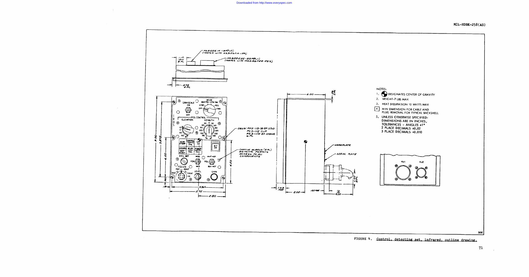
4.1.4 Control, detecting set, infrared. This unit provides all IRDScontrol functions except for video indicator controls and the sight con-trol. All power to the AN/AAS-36 is controlled by the mode selector.A grey scale control switch is provided. Manual elevation and azimuthposition controls permit selective positioning of the receiver-converter LOS with the mode selector in POS. Six status indicators anda bit control on demand only provide system status. A RTCL BRT(reticle brightness), LEVEL, and GAIN pots provide operator control ofthese functions. A focus control provides four, manual selectablefocus options to the operator. FOV (field of view) and POL (polarity)switches permit operator selection of narrow or wide field of view andwhite or black hot images.
When the mode select is in CPTR TRK position, the IRDS will acceptdata processing system generated rate commands. Depressing the triggerswitch on the sight control permits operator override of computer trackbut the target position to the computer is continuously available. Inthe MAN mode, receiver-converter LOS is directed by operation of thesight control.
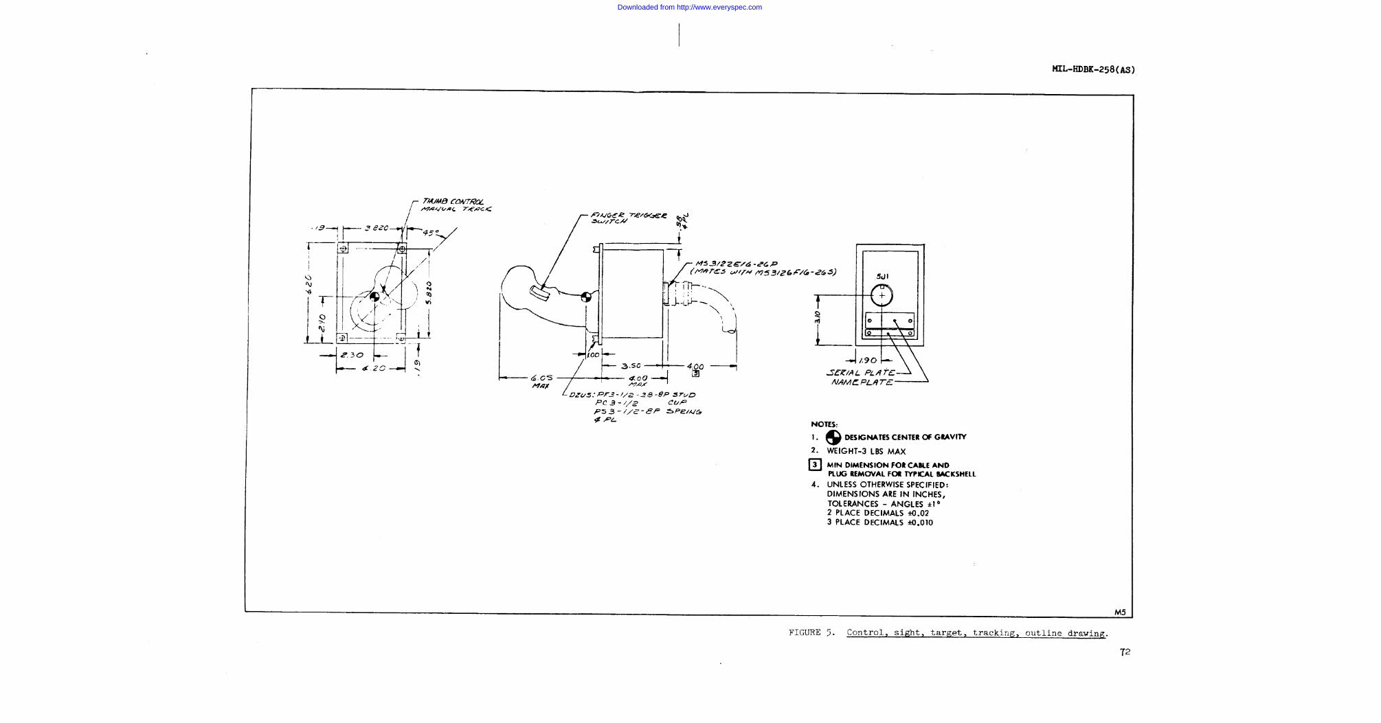
4.1.5 Control, sight, target tracking. This unit provides formanual control of the receiver converter when the mode is set to MAN,and permits override of CPTR TRK. Overriding CPTR TRK, by depressingthe trigger switch, disconnectsnew turret position(s) directeddata processing system when the
data processing system control. Theby the operator are transferred to theswitch is released.
7
Downloaded from http://www.everyspec.com
MIL-HDBK-258(AS)
Receiver-converter manual positioning is controlled by a thumb ballon top of the control - fore/aft motion causes correlated motion of LOSin elevation, left/right pressure causes the receiver LOS to movecounterclockwise/clockwise proportionally to the applied pressure.
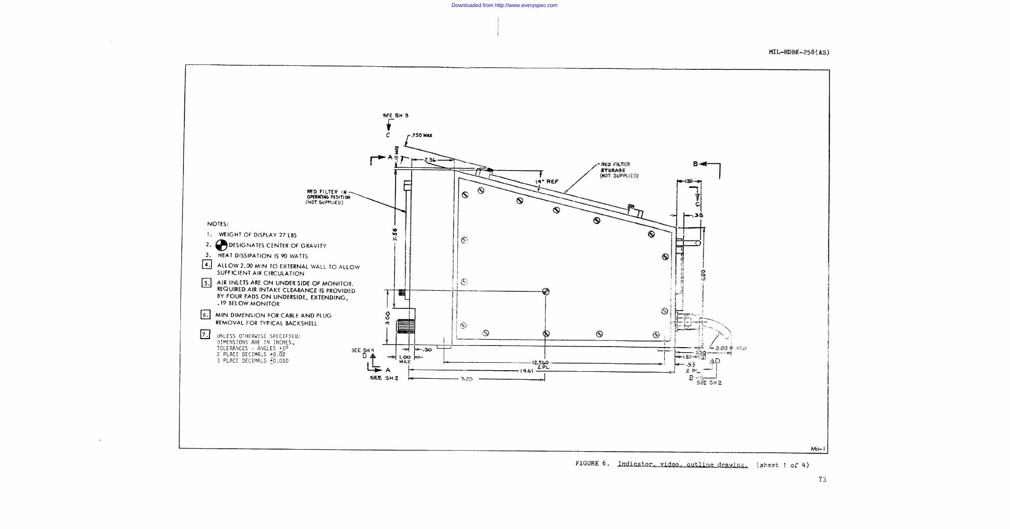
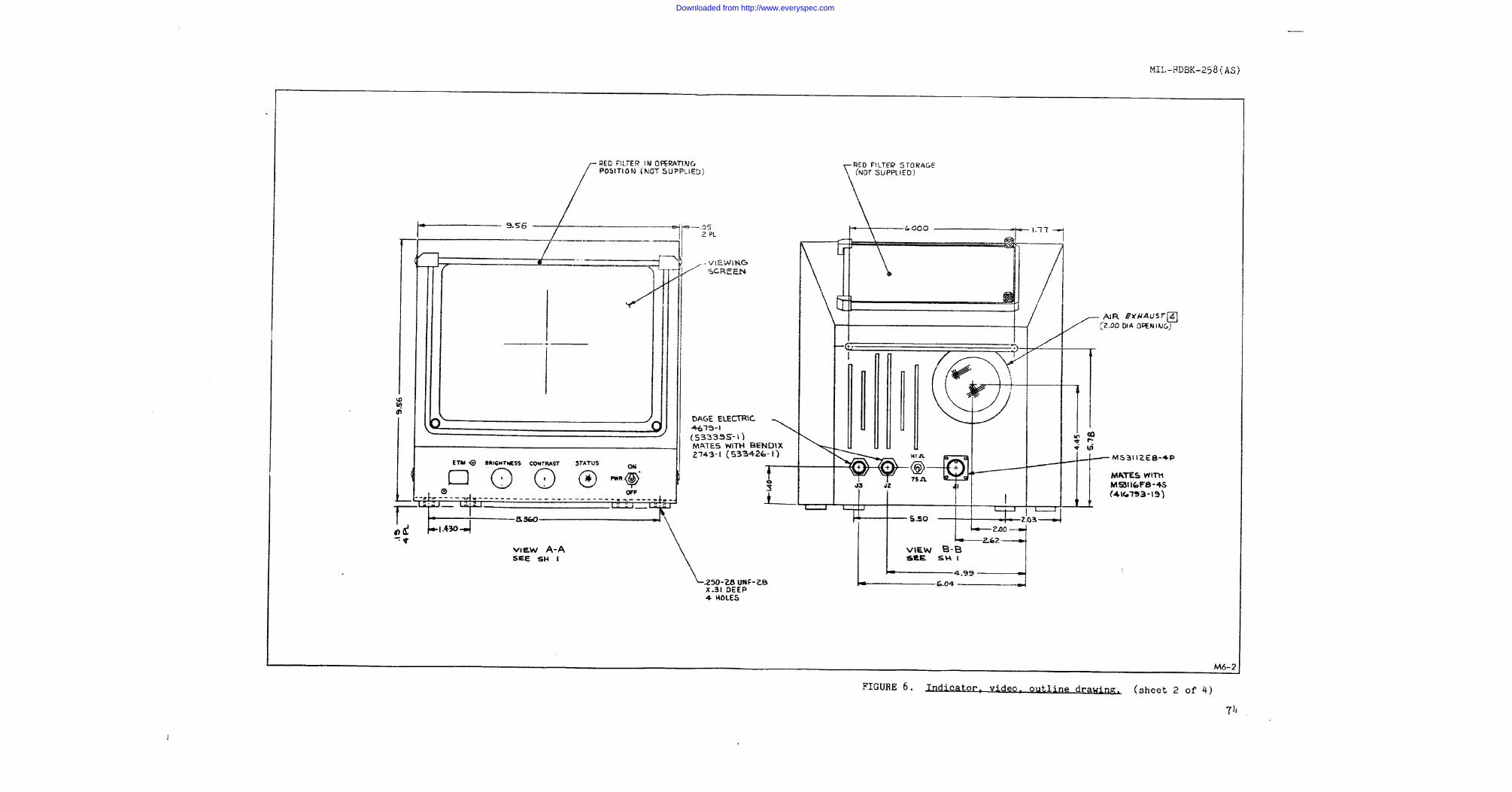
4.1.6 Indcator, video. This unit, a 9N display, provides the videoimage to the operator. Gimbal angle indicators located on the leftside and top of the unit provide direct readout of the receiver-con-verter LOS relative to the aircraft. The unit provides a 32:1 contrastratio with a capability of displaying ten grey shades.
This unit requires 115 V 400 Hz aircraft power, and is a self-contained unit. Power to the unit is controlled by the IRDS control.Brightness and contrast controls are operator adjustable. A poweron/off switch is also provided. Impedance switching between hi and 75ohms is provided on the rear as are two triax video connectors.
4.2 Overall characteristics. The operational requirements of theIRDS as well as the sensitive infrared receiver performance character-istics such as spectral bandpass, square wave response, minimum resolv-able temperature and noise equivalent temperature differential areclassified (Confidential) and may be obtained from corresponding para-graph references in AS-3900A.
4.3 Aircraft installation. The following provides installationlimitations and precautions for the six IRDS weapons replaceableassemblies.
4.3.1 Receiver converter.
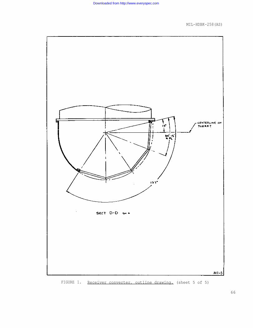
4.3.1.1 Location of the unit. This unit contains the gimbaledreceiver. Its aperture must be mounted so that energy can be receivedfrom at least the lower hemisphere under the aircraft. The outlinedimension drawing (see figure 1) defines the aperture location withrespect to the mounting structure and shows gimbal angle coverage. Thelower forward portion of the aircraft fuselage is a preferred location.
Buffeting that could be caused by propellers or skin discontinuitiesshould be avoided.
Damage to the optical window that could be caused by debris from thelanding gear or by leaks from a hydraulic system should be avoided.
8
4.3.1.2 Limits to normal operation attitude. The forward directionis shown on the outline dimension drawing. The unit should be mountedparallel to aircraft FRP to provide correct gimbal angle readouts andprevent tilting of the displayed infrared image. Receiver-converteralignment requirements are defined in paragraph 5.1.5.
Downloaded from http://www.everyspec.com
MIL-HDBK-258(AS)
4.3.1.3 Precautions.
a.
b.
c.
d.
e.
f.
g.
h.
i.
j.
Avoid sharp bends in all cables
Maximum length of cables to the receiver converter is 40feet
Provide access at top for connectors
Avoid excessive loading by the mounting structure thatcould cause gimbal binding
Maintain air space and circulation around upper shroudto maintain cooling
Provide overhead access for hoisting into place (seefigure 1 for hoisting eye location)
Provide access for boresight pins
10 Azimuth pin shown on outline dimension drawing
2. Elevation pin access is attained by removal of the20-inch diameter turret
Provide proper
Provide accessposition
Provide access
grounding of unit for personnel safety
to elapsed time meter when in stowed
for turret window cleaning
4.3.1.4 Mounting instructions. A rigid mounting structure isrequired that securely restrains the unit at the four perimeterlocations.
4.3.2 Powe supply - video converter.
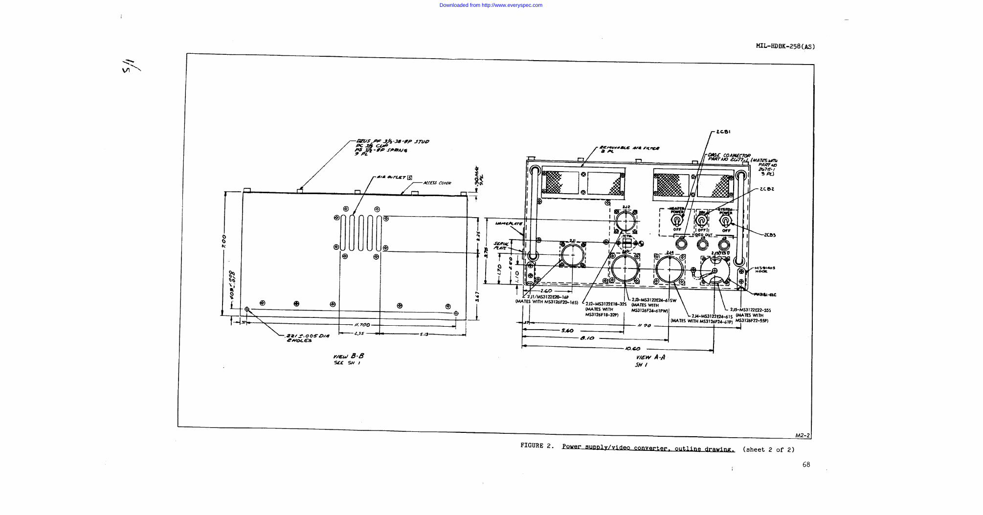
4.3.2.1 Location of unit. The Power Supply - Video Converter,PP-7267/AAS-36 will be located in a conventional equipment mountingarea as near as possible to the other interconnected WRA'S to minimizecable lengths.
4.3.2.2 Limits to normal operation attitude.Video Converter, PP-7267/AAS-36 may be operatedeasiest maintenance, it should be approximately
The Power Supply -in any attitude. Forlevel.
9
Downloaded from http://www.everyspec.com
MIL-HDBK-258(AS)
4.3.2.3 Precautions.
a.
b.
c.
d.
e.
f.
g.
Avoid sharp bends in all cables
Provide access in front of unit for electricalconnectors and elapsed time meter
Provide proper grounding for personnel safety
Provide air space and circulation around filters infront and the fan outlet in the rear of unit
Avoid excessive loading in mounting that could damagecase
Provide clearance for drainhole in bottom of unit
Provide access for filter cleaning maintenance
4.3.2.4 Mounting instructions. The power supply-video converter isdesigned for use on a mounting base such as prescribed in MIL-C-172Cexcept for non-standard size and fastener spacing.
4.3.3 Control-servomechanisms.
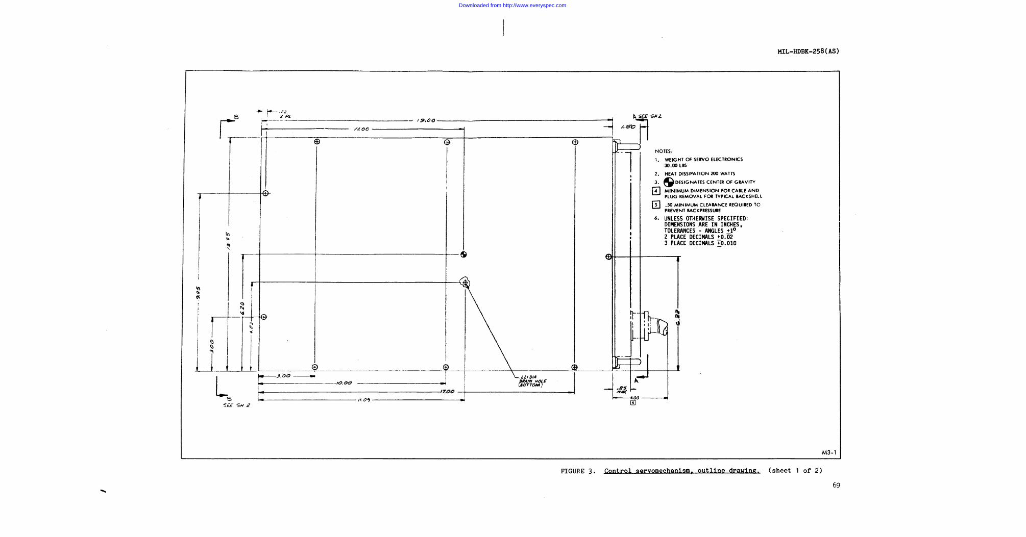
4.3.3.1 Location of unit. The Control-Servomechanism, C-9982/AAS-36will be located in a conventional equipment mounting area as near aspossible to the other interconnected WRA's to minimize cable lengths.
4.3.3.2 Limits to normal operation attitude. The Control-Servo-mechanism C-9982/AAS-36 may be operated in any attitude. For easiestmaintenance, it should be approximately level.
4.3.3.3 Precautions.
a.
b.
c.
d.
e.
Avoid sharp bends in all cables
Provide access in front of unit for electricalconnectors and elapsed time meter
Provide proper grounding for personnel safety
Provide air space and circulation around filters infront and the fan outlet in the rear of unit
Avoid excessive loading in mounting that could damagecase
10
Downloaded from http://www.everyspec.com
MIL-HDBK-258(AS)
f. Provide clearance for drainhole in bottom of unit
g. Provide access for filter cleaning maintenance
4.3.3.4 Mounting instructions. The Control-Servomechanism C-9982/AAS-36 is designed for use on a mounting base such as described inMIL-C-172C except for non-standard size and fastener spacing.
4.3.4.1 Location of unit. Control, Detecting Set, Infrared, C-9983/AAS-36 shall be mounted in the IRDS AN/AAs-36 operator’s station asnear as possible to interconnecting units to minimize cable lengths (40foot maximum cable length). The unit should be located for easy accessto controls in flight. Unit is to be operated in conjunction with theControl, Sight, Target Tracking, C-9984/AAS-36 and the Indicator,Video, IP-1240/AAS-36.
4.3.4.2 Limits to operation attitude. Control, DetectingSet, Infrared, C-9983/AAS-36 may be mounted in any attitude that meetsparagraph 4.3.4.1 requirements.
4.3.4.3 Precautions.
a. Avoid sharp bends in all cables
b. Provide service length in cables for unit installationand removal
co Provide proper grounding for operators safety
4.3.4.4 Mounting Instructions. Control, Detecting Set, Infrared,C-9983/AAS-36 shall be mounted as described in MS25213.
4.3.4.5 Environmental limits. The Control, Detecting Set, Infrared,C-9983/AAS-36 is limited to 15,000 feet altitude operation (may beoperated at higher altitudes in a pressurized area).
4.3.5 Control, sight. target tracking.
4.3.5.1 Location of unit. Control, Sight, Target Tracking C-9984/AAS-36 will be located in the IRDS operator's station as near as possi-ble to interconnecting units in order to minimize cable lengths (40foot maximum cable length). The unit should be located for ease ofoperation. The unit is operated in conjunction with the Control,Detecting Set, Infrared, C-9983/AAS-36 and the Indicator, VideoIP-1240/AAS-36.
11
Downloaded from http://www.everyspec.com
MIL-HDBK-258(AS)
4.3.5.2 Limits to normal operation attitude. Control,Tracking C-9984/AAS-36 may be mounted in any attitude forconvenience.
4.3.5.3 Precautions.
a. Avoid sharp bends in cable
Sight, Targetoperator
b. Provide service length in cable for unit installationand removal
c. Provide proper grounding for operator’s safety
4.3.5.4 Mounting instructions. The Control, Sight, Target TrackingC-9984/AAS-36 shall be mounted similar to the method described inMS25213 except spacing of fasteners is not standard.
4.3.5.5 Environmental limits. The Control, Sight, Target TrackingC-9984/AAS-36 is limited to 15,000 feet ambient altitude operation (maybe operated at higher altitudes in a pressurized area).
4.3.6 Indicator, video.
4.3.6.1 Location of unit. The Indicator, Video IP-1240/AAS-36 willbe located in the IRDS operator's station, as near as possible to inter-connecting units, “to minimize cable lengths (maximum cable length is 40feet). The indicator should be located for easy access to operatorcontrols and should be positioned for comfortable viewing (18 to 24inches from operator’s eyes). The indicator is operated in conjunctionwith the Control Detecting Set, Infrared, C-9983/AAS-36 and theControl, Sight, Target Tracking, C-9984/AAS-36.
4.3.6.2 Limits to normal operation attitudes. The Indicators, VideoIP-1240/AAS-36 may be mounted in any attitude for operator convenience.
4.3.6.3 Precautions.
a. Avoid sharp bends in all cables
b. Provide proper grounding for operatorss safety
c. Provide air space and circulation around bottom intakefilters and fan outlet in rear of unit
d. Provide access to air filter in bottom of unit formaintenance
12
Downloaded from http://www.everyspec.com
MIL-HDBK-258(AS)
e. Mount in an area of low illumination and protect screenfrom glare and reflected light
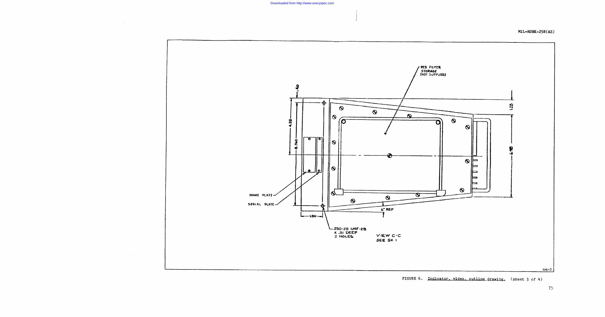
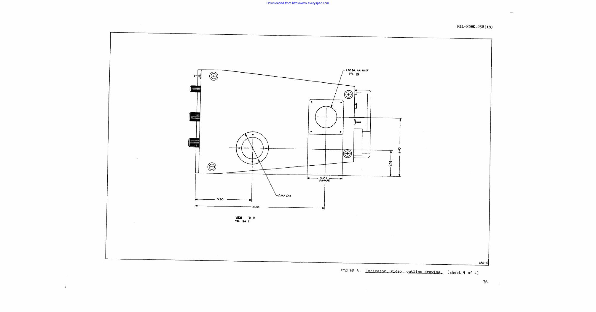
4.3.6.4 Mounting instructions. The Indicator, Video IP-1240/AAS-36shall be mounted by the 4 holes in the bottom. The 0.19 inch clearanceprovided by the mounting pads shall not be obstructed to insureadequate cooling air inlet. Leave space for removal of air filters.
4.3.6.5 Environmental limits. The Indicator, Video IP-1240/AAS-36is limited to 15,000 feet altitude operation (may be operated at higheraltitudes in a pressurized area).
13
Downloaded from http://www.everyspec.com
MIL-HDBK-258(AS)
5. DETAILED STATEMENT OF REQUIREMENTS
5.1 AN/AAS-36 (IRDS)/aircraft interfaces. The infrared detectingset consists of six weapon replaceable assemblies requiring electricalinterconnection with each other and with other aircraft systems.Mechanical interface details including WRA outline dimension drawings,aircraft location and installation requirements, thermal characteris-tics etc. are presented in paragraph 5.1. Electrical interface detailsincluding input power requirements, cable division and aircraft subsys-tem interface interconnection, connector types, detail pin and wireassignments, grounding, shielding, interface timing, etc. are presentedin paragraphs 5.2 and 5.3.
Every consideration shall be given in location of equipment and indesign of installation details to promote operator efficiency andmaintenance facility.
5.1.1 Mechanical.
5.1.1.1 WRA(outline dimention drawings). Outline dimension draw-ings for the IRDS WRA’s are provided in figures 1 through 6. T h eoutline drawings include weight, center of gravity, maximum heat dissi-pation and special installing instructions/notes, in addition to thedimensional information for each WRA.
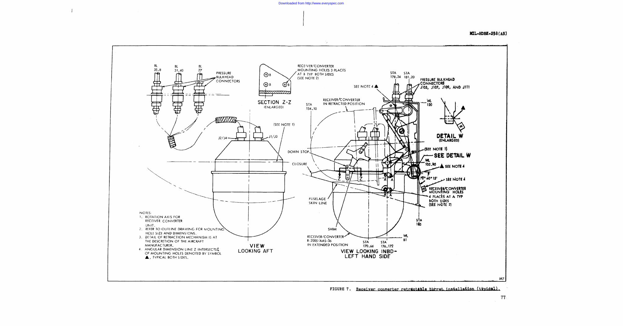
5.1.2 [retractable turret (typical).Aircraft installation Thelocation and mechanical interface for the IRDS receiver converter isshown in figure 7 for a typical (P-3C) retractable turret installation.
5.1.3 Aircraft installation fixed turret(typical) The locationand mechanical interface for the IRDS receiver converter is shown infigure 8 for typical fixed turret installations.
5.1.4 Thermal character/requirements. The heat dissipation,air inlet and air outlet sizes and locations for each IRDS unit aregiven in outline figures 1 through 6. Minimum distance from an obstruc-tion to an air outlet opening is also indicated in the outline figures.
5.1.5 Receiver converter aircraft alignment accuracy requirements.In the computer track mode, the data processing system, utilizingsensed target location (relative to the aircraft), will provide IRDSLOS pointing (rate) commands. The computer will utilize targetazimuth, target range and aircraft altitude to continuously predictIRDS elevation and azimuth angles to intercept the designated target.These angles will utilize the fuselage reference planes (FRP) as theorigin. Proper rate (az and el) commands will be generated andprovided to the IRDS to position the LOS on the target. A designated
14
Downloaded from http://www.everyspec.com
MIL-HDBK-258(AS)
target will fall within the narrow FOV under computer control when allexternal system errors are limited to 2.4 degrees elevation and 3.2degrees azimuth (3 sigma values) and the stabilized turret platform isaligned to the FRP within 0.50 degree.
Note: Any relaxation of this installation requirement will result ina decrease in the allowable system error to provide the same acquisi-tion probability.
5.1.6 Receiver-converter assembly - mechanical alignment check -
should be accomplished when a receiver converter is fitted to a retrac-tion package.
a. Down stop engagement on both sides shall be adjusted forminimum contact unbalance with the receiver converter inits fully extended position (no extension load), toprevent excessive warpage within the receiver-convertermain casting.
b. With the receiver converter fully extended, the angulardimension of 72° ±0° 15' shown in figure 7 should beverified.
5.1.7 Receiver-converter assembly - mechanical alignment check -fixed turret (refer to figure 8).
5.2 Electrical.
5.2.1 Aircraft powerl
5.2.1.1 Aircraft power characteristics. The characteristics of theelectrical power supplied to the AN/AAS-36 shall be as follows:
a.
b.
AC Power - The AC power system shall be a 3 phase,4-wire WYE System, having a nominal voltage of 115/200VRMS and a nominal frequency of 400 Hertz. The neutralpoint of the source of power is connected to ground andthe ground is considered the fourth conductor. The ACpower characteristics shall be within the limits ofMIL-STD-704A for category B equipment.
DC Power - The DC power system shall be a 2-wire,grounded system having a nominal voltage of 28 VDC. Thenegative of the power source is connected to ground andground is considered the second wire. The DC powercharacteristics shall be within the limits ofMIL-STD-704A for category B equipment.
15
Downloaded from http://www.everyspec.com
MIL-HDBK-258(AS)
5.2.2 Equipment power requirements.
5.2.2.1 AN/AAS-36 input power. The AN/AAS-36 equipment shalloperate within specified limits when supplied with category B,MIL-STD-704A power except as modified herein. The equipment shalloperate within the bounds of MIL-STD-704A, figure 3, limits 2 and 3,except the lower limit of curve 3 shall not fall below 80 volts.Equipment malfunction may occur when the input voltage exceeds theabove limits but remains within limits 1 and 4 (MIL-STD-704A, figure3). However, no damage to the equipment shall result when subjected tothe following conditions:
a. Loss of power - Accidental or deliberate stoppage ofelectrical power, regardless of the time in equipmentoperating cycle and regardless of duration of stoppage.
b. Under and overvoltage - Voltages below the minimum or upto 125 percent of the maximum emergency steady statespecified in MIL-STD-704A.
c. Transients - Transient voltage surges that, whenconverted to their equivalent step functions, are withinthe limits of figure 3 of MIL-STD-704A.
d. Phase Reversal or Phase Loss - The reversal of any ACphase or the loss of any combination of AC phases.
Normal operation of equipment shall be automatically resumed uponreturn of the input voltage to levels within limits 2 and 3(MIL-STD-704A, figure 3) as modified herein, and/or restoration ofproper rotation.
5.2.2.2 AN/AAS-36 input power requirements. Maximum power require-ments for the infrared detecting set are as follows:
3 phase 115/200 VRMS 3000 VA28 VDC 140 VA18 VDC 28 VA
The IRDS power requirements as a function of operating mode arepresented in table I.
16
Downloaded from http://www.everyspec.com
MIL-HDBK-258(AS)
TABLE I. IRDS input power requirements (maximum steady state).
IRDS panel lighting requires 5 to 28 VDC power (0.5 amps at 28 VDC)
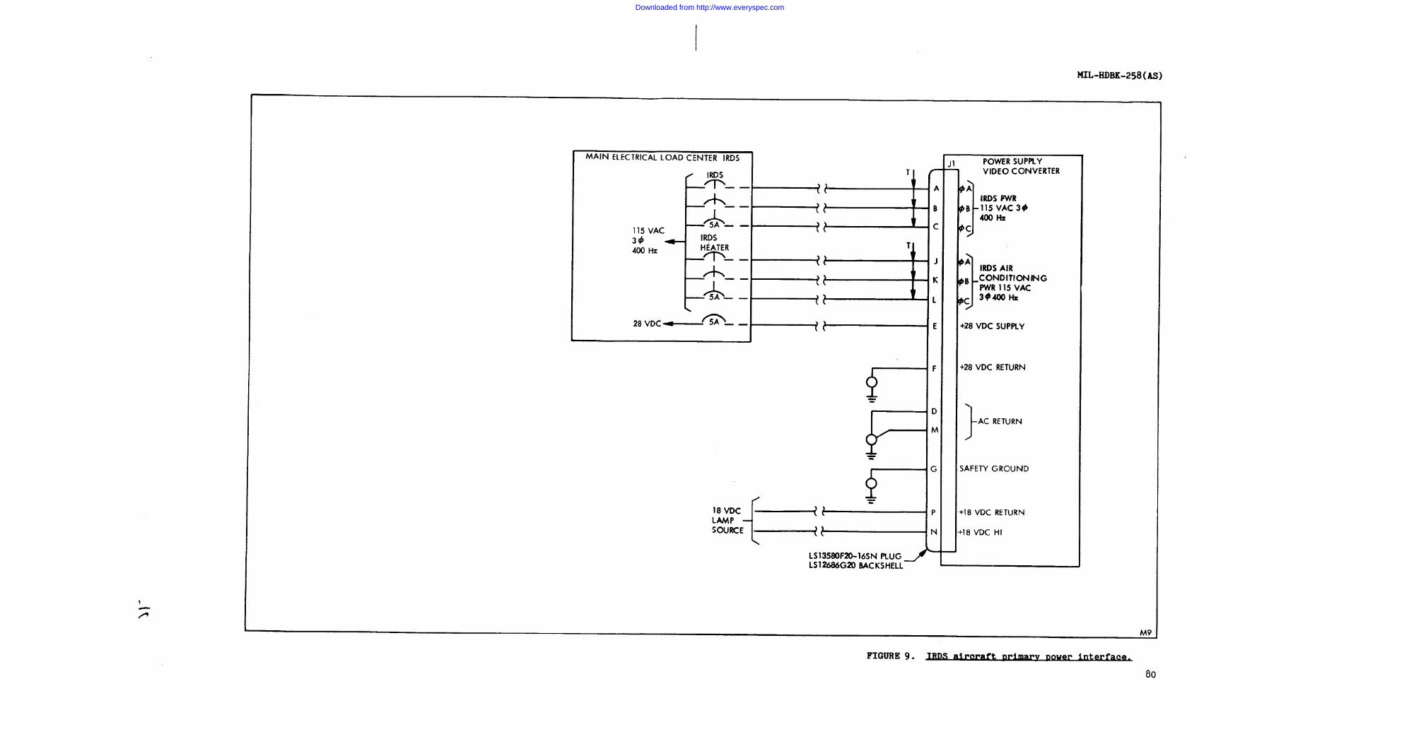
5.2.2.3 IRDS/aircraft electrical system interface. Overall inter-face of the IRDS and aircraft 3 phase 115/200 VRMS and 28 VDC primarypower sources and 18 VDC indicator lamp power source is presented infigure 9.
5.2.2.3.1 IRDS/aircraft electrical system interface. A 5 to 28 VDCpanel edge light power signal is provided to the IRDS control,detecting set. The edge panel light load shall be 0.5 amp maximum.
5.2.2.3.2 IRDS/lamp test power source interface. An 18 VDCindicator lamp test signal is provided to the IRDS control, detectingset. The indicator lamp test load shall be 1.0 amp maximum.
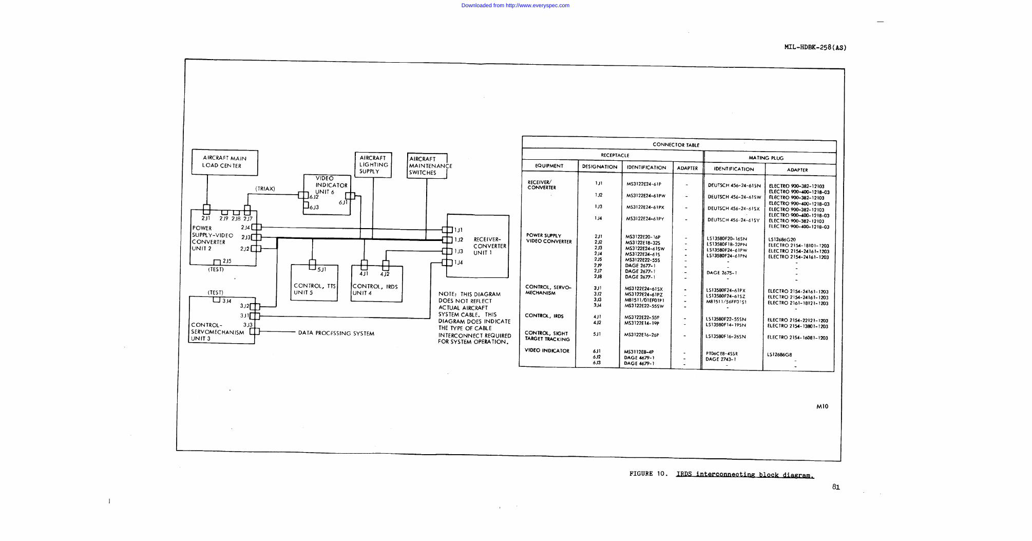
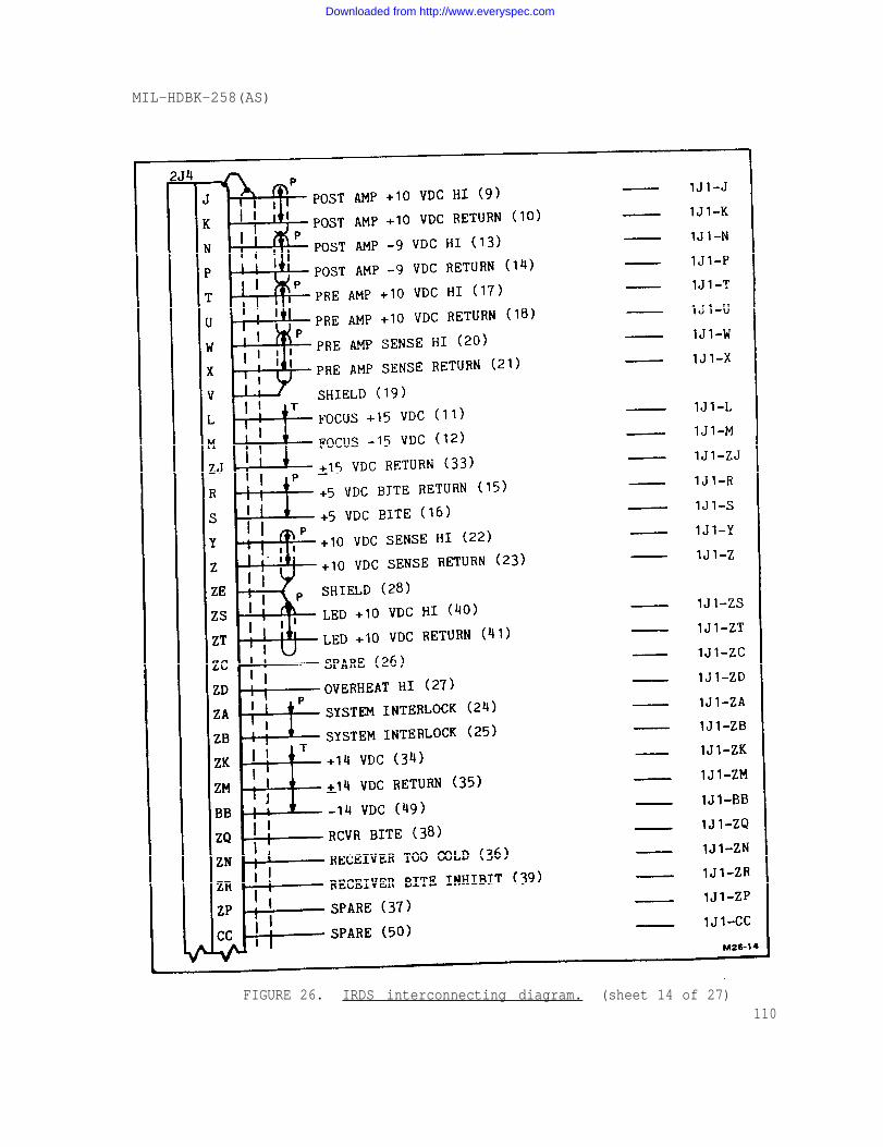
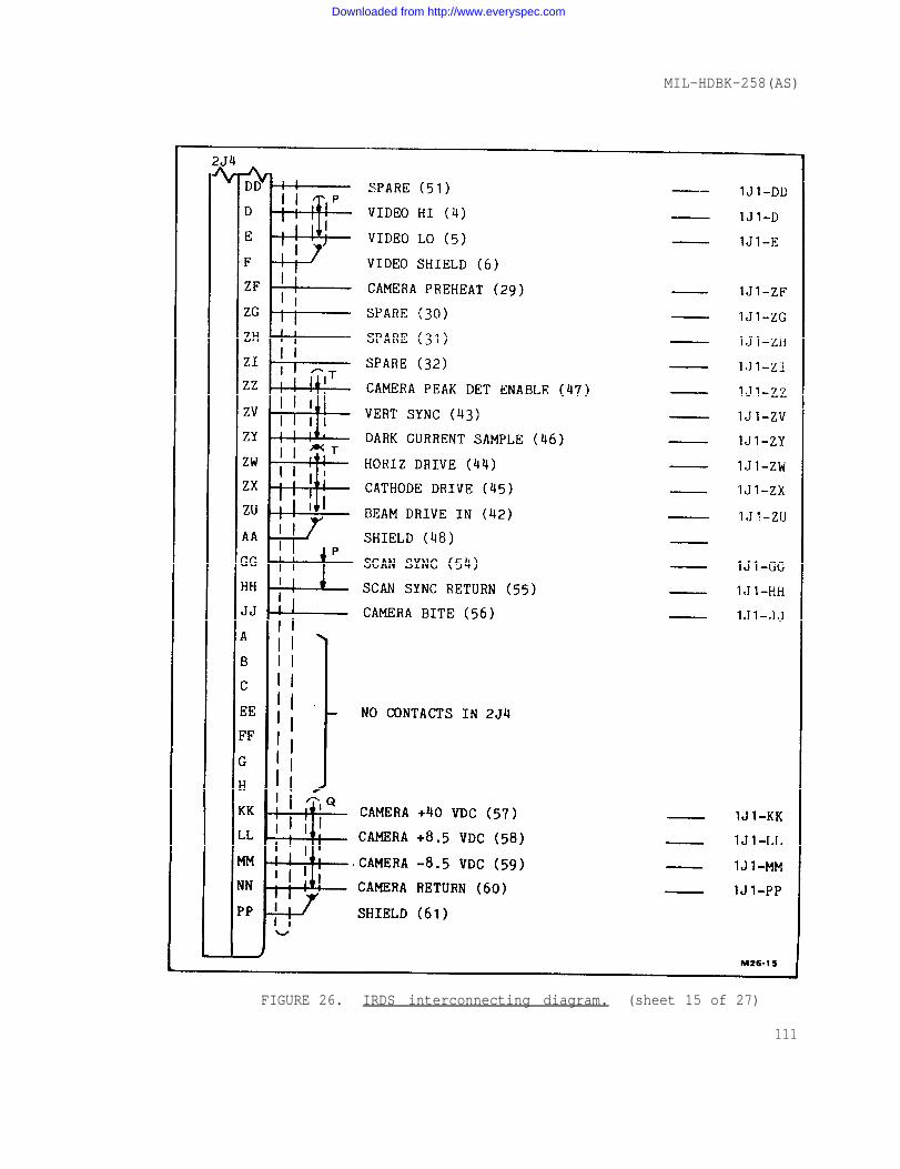
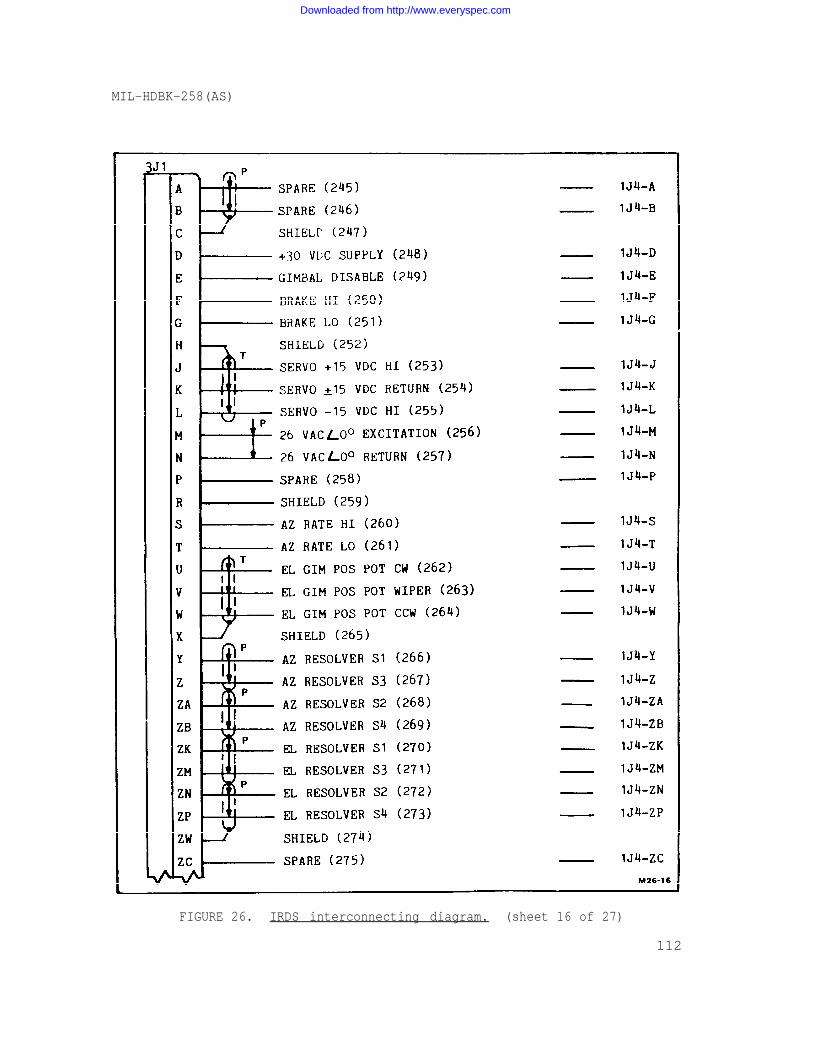
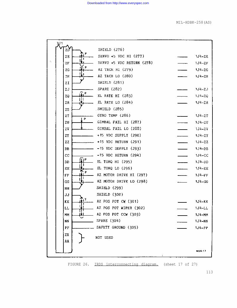
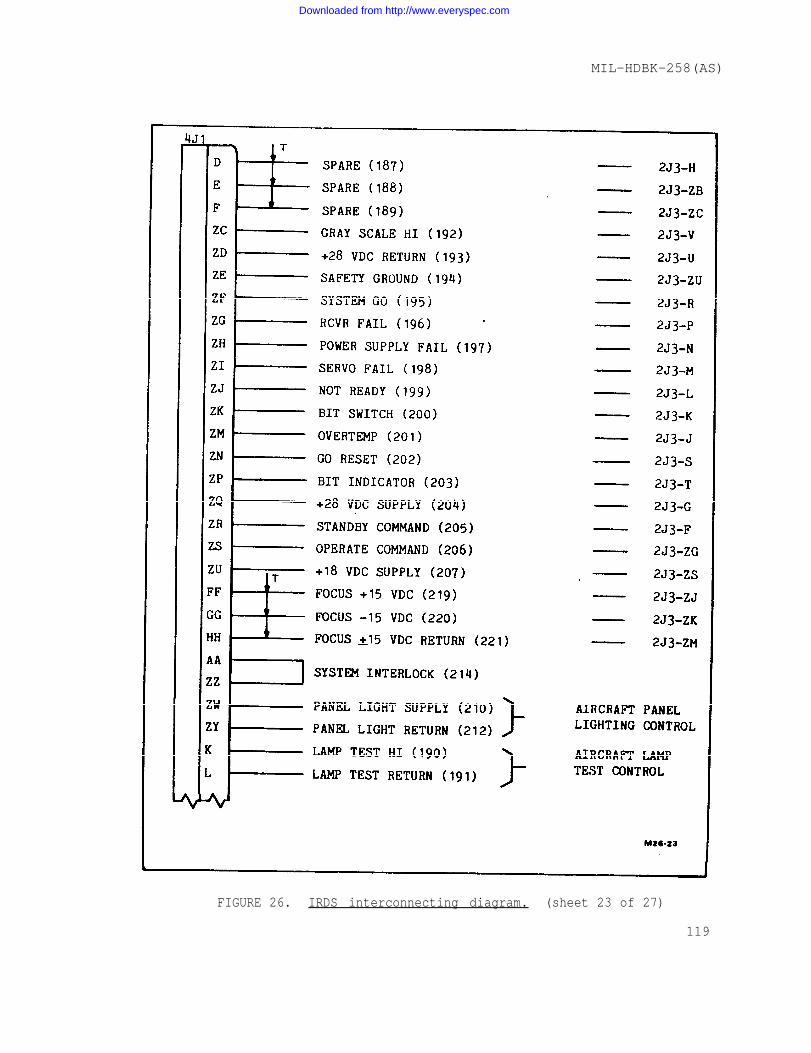
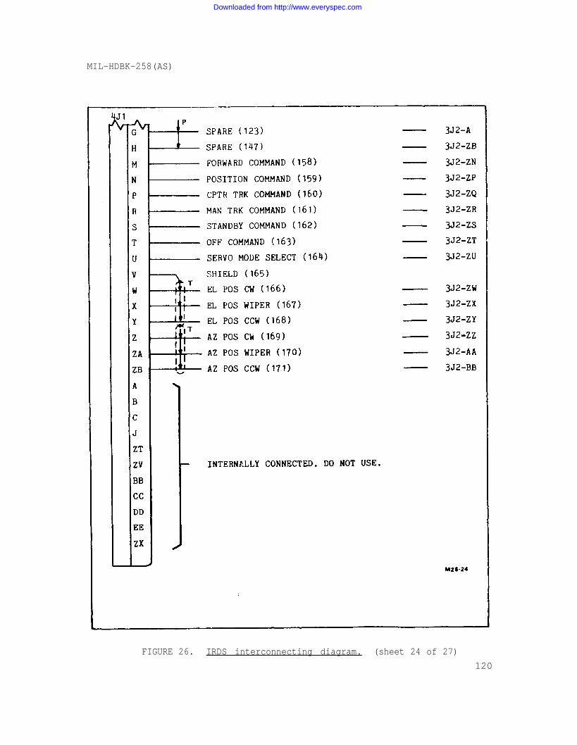
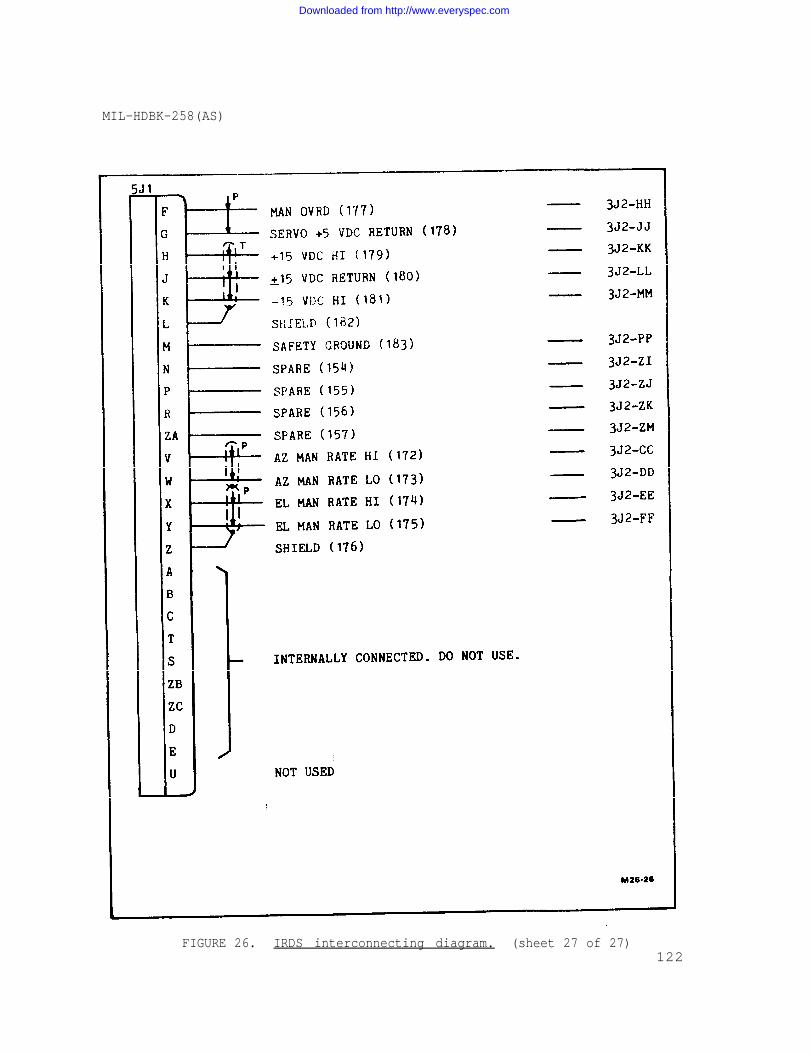
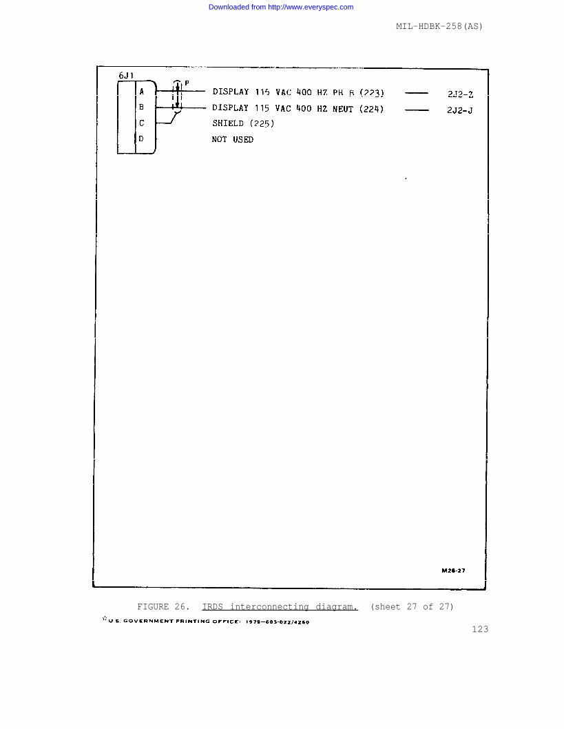
5.2.3 Interconnection diagrams. Electrical interconnections arerequired between the six IRDS weapon replaceable assemblies (WRA) andbetween the applicable IRDS WRA's and other aircraft systems. Cabledivision and a cable connection identification chart are presented infigure 10, IRDS interconnection block diagram.
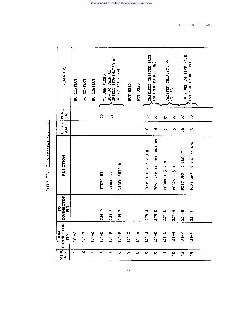
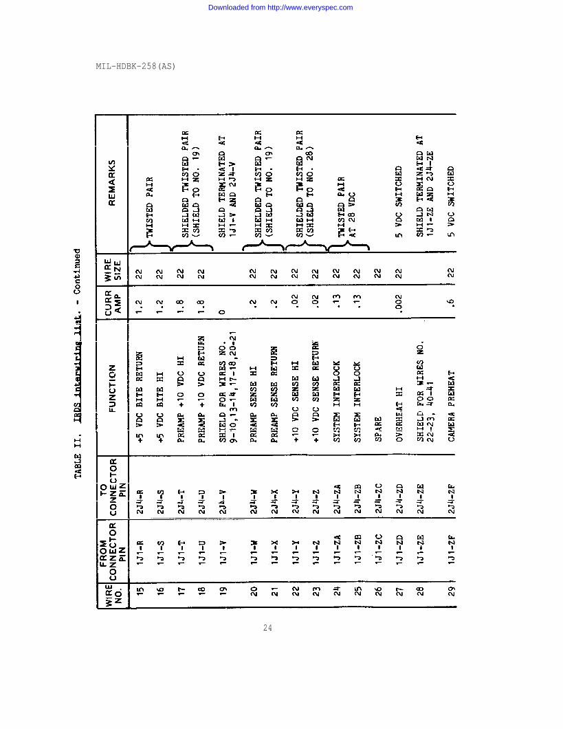
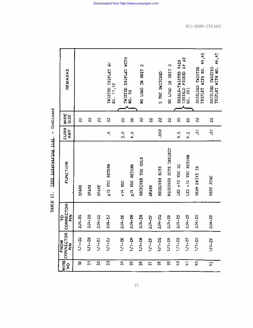
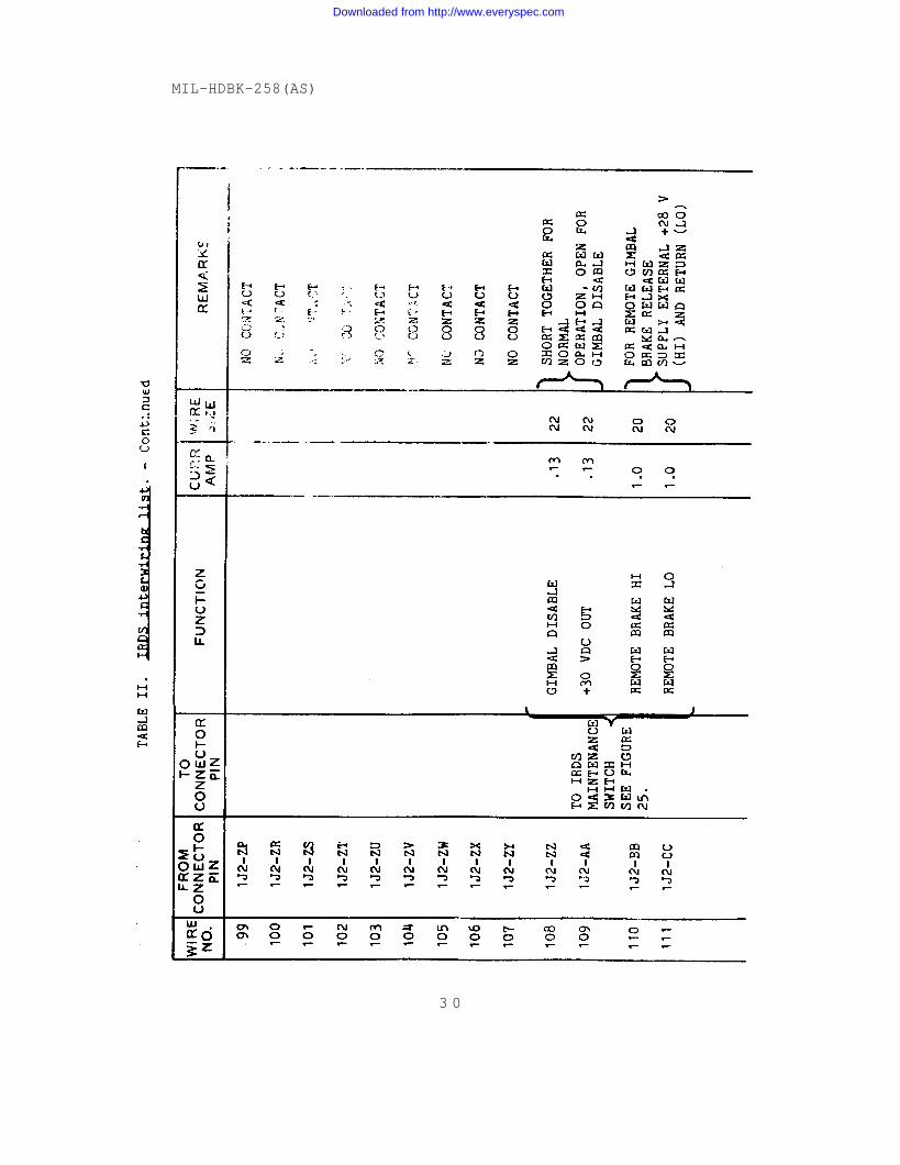
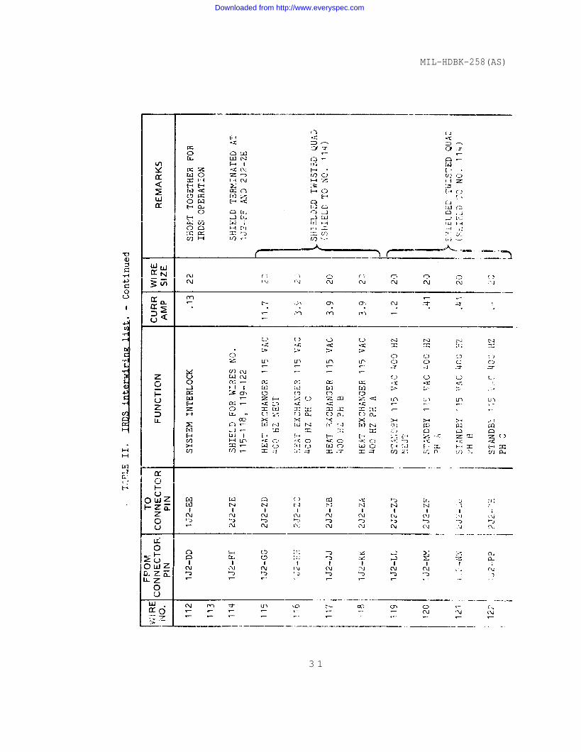
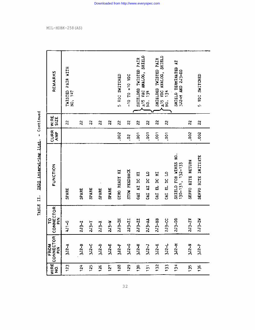
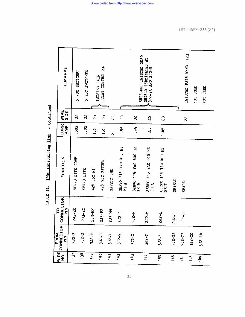
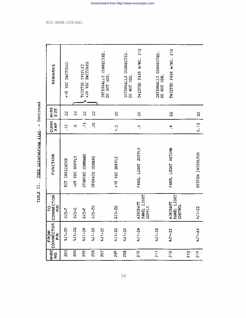
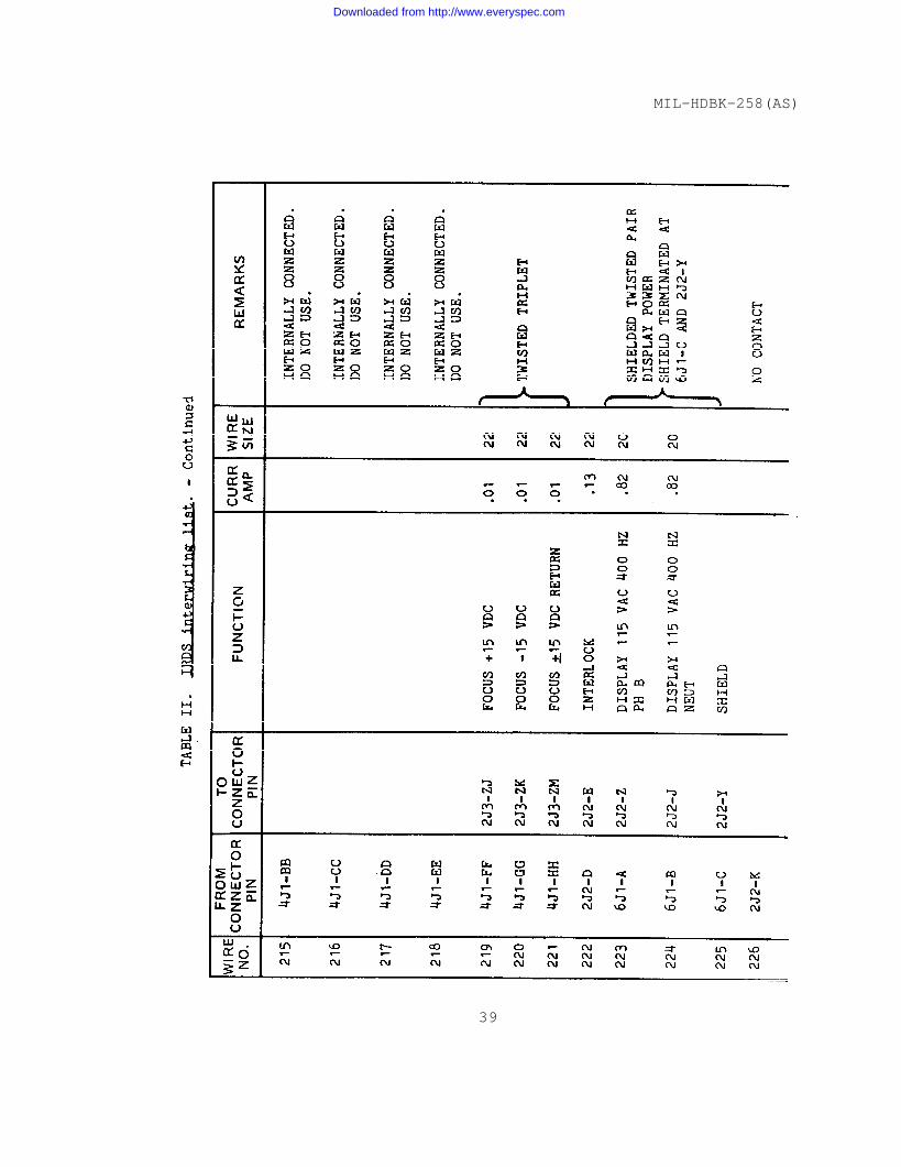
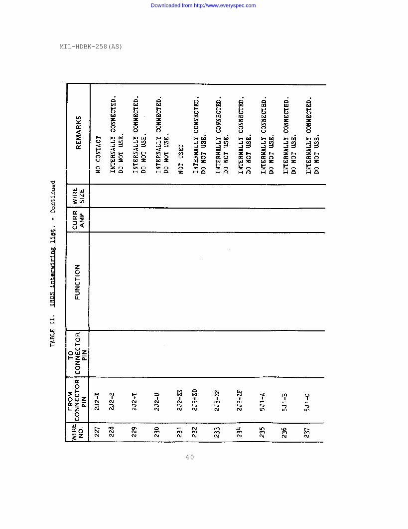
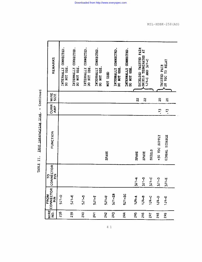
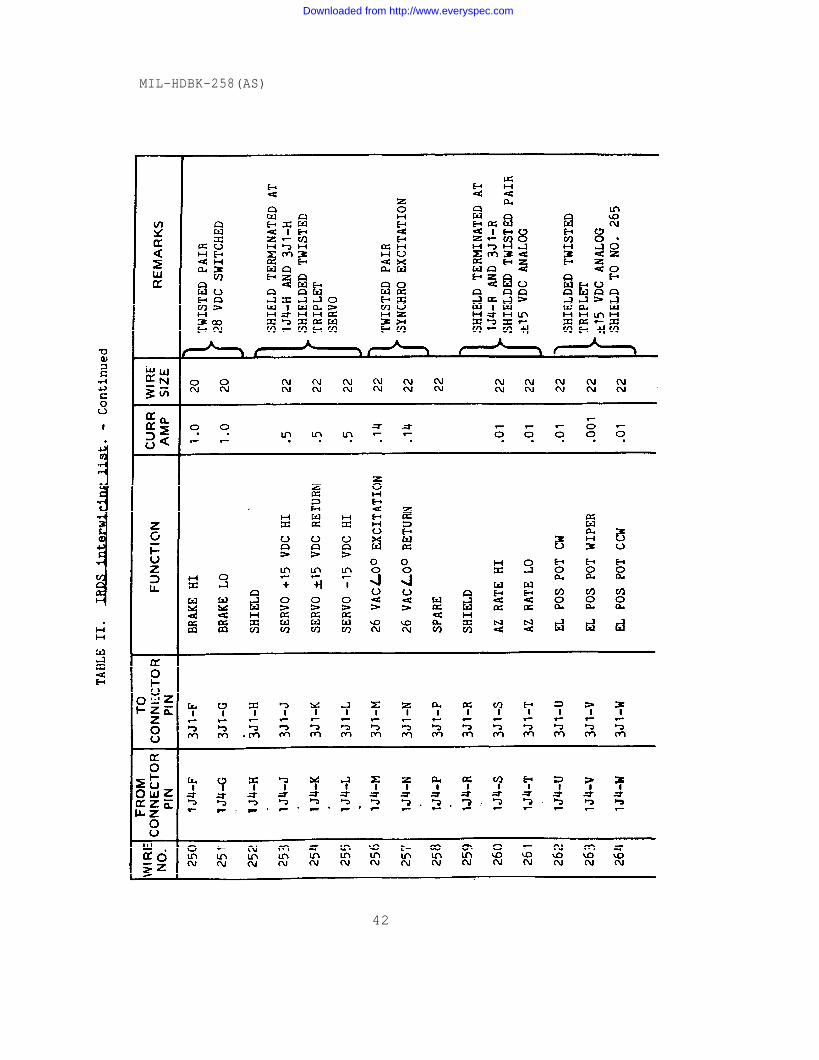
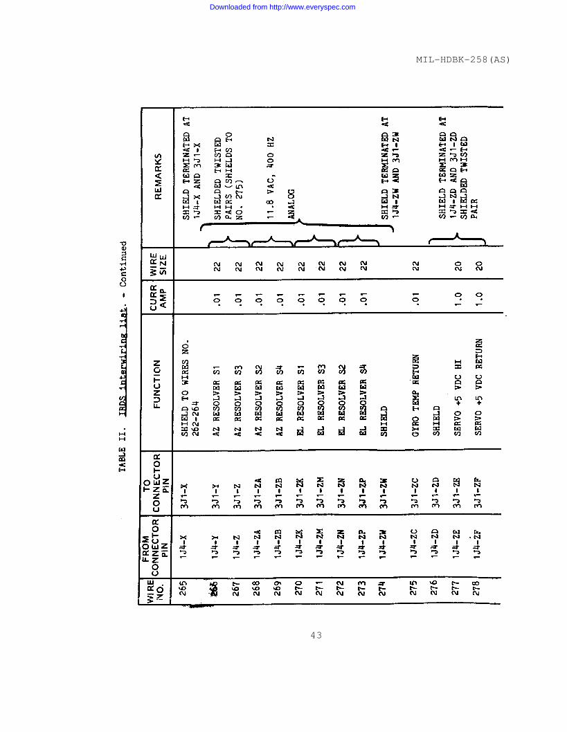
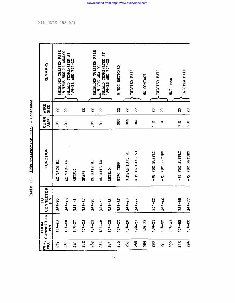
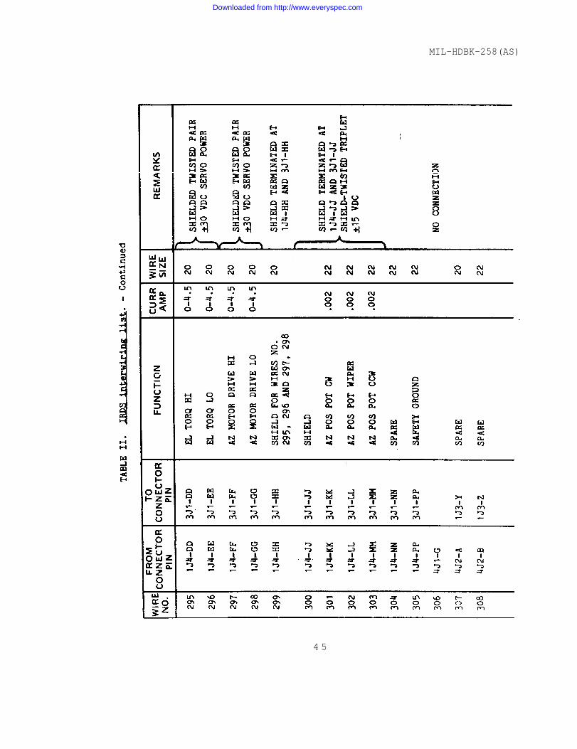
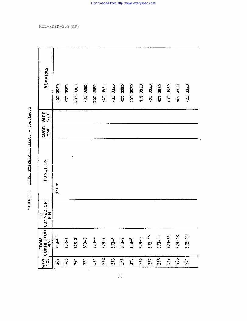
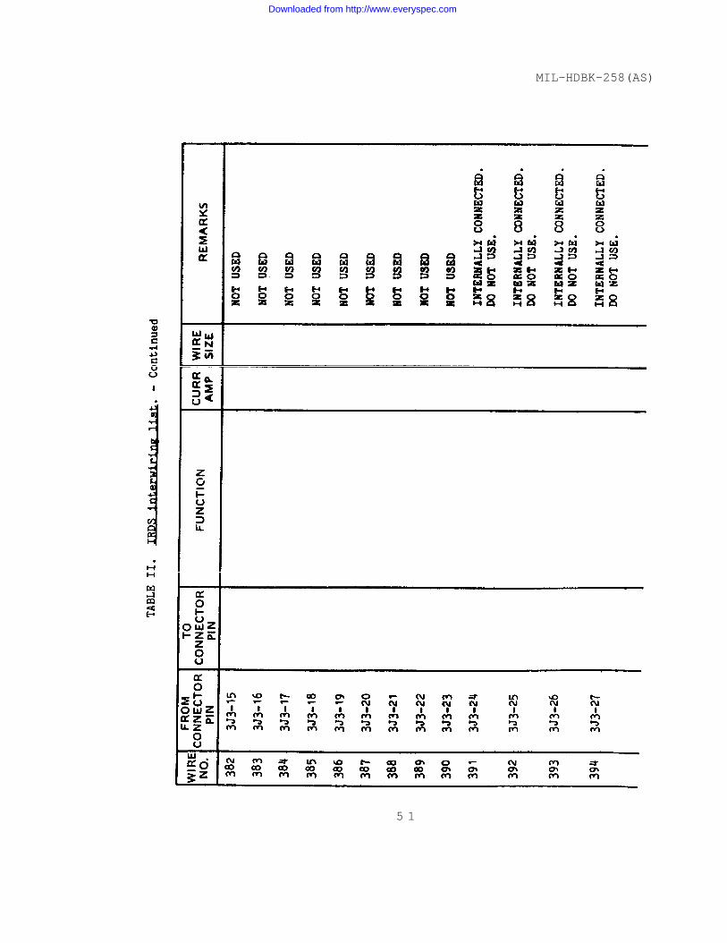
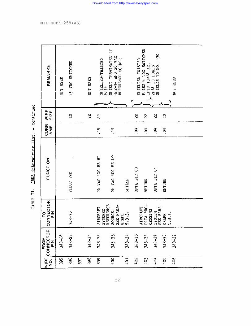
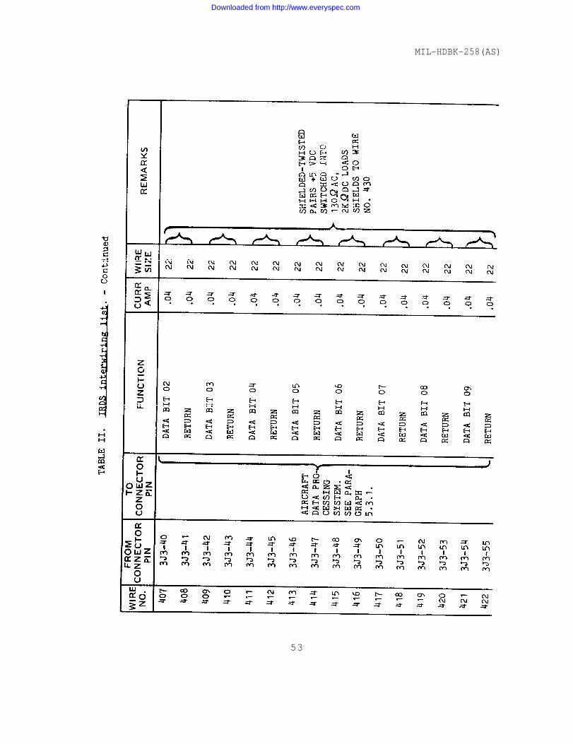
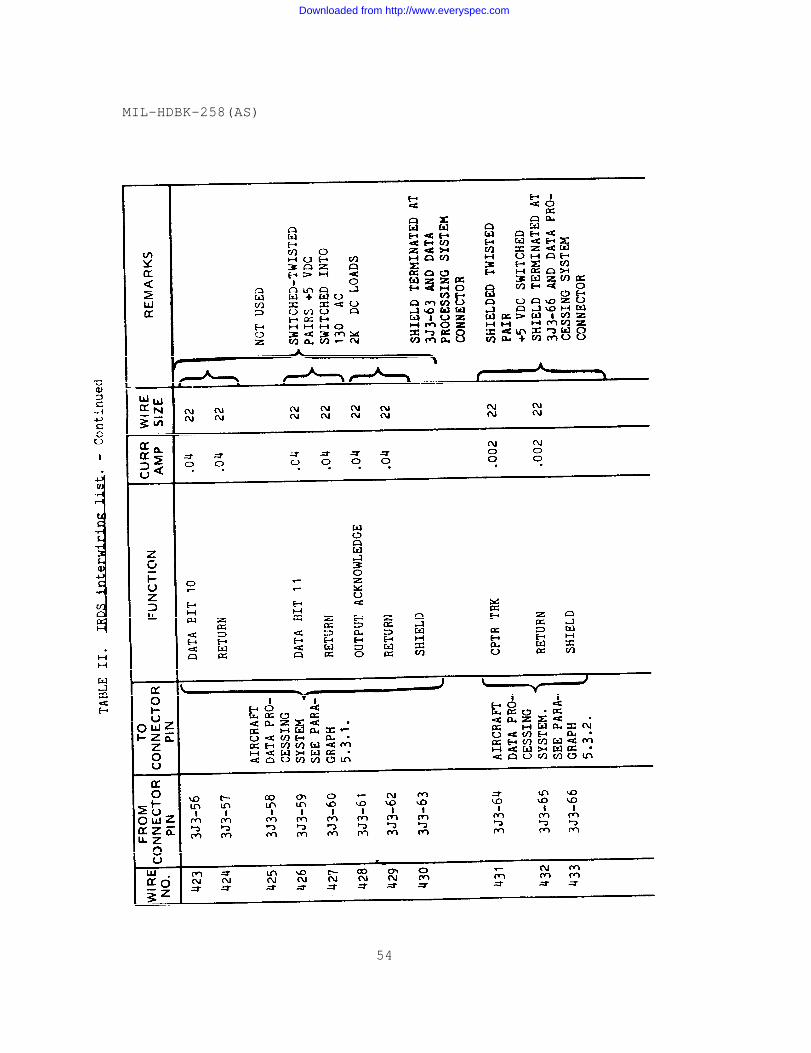
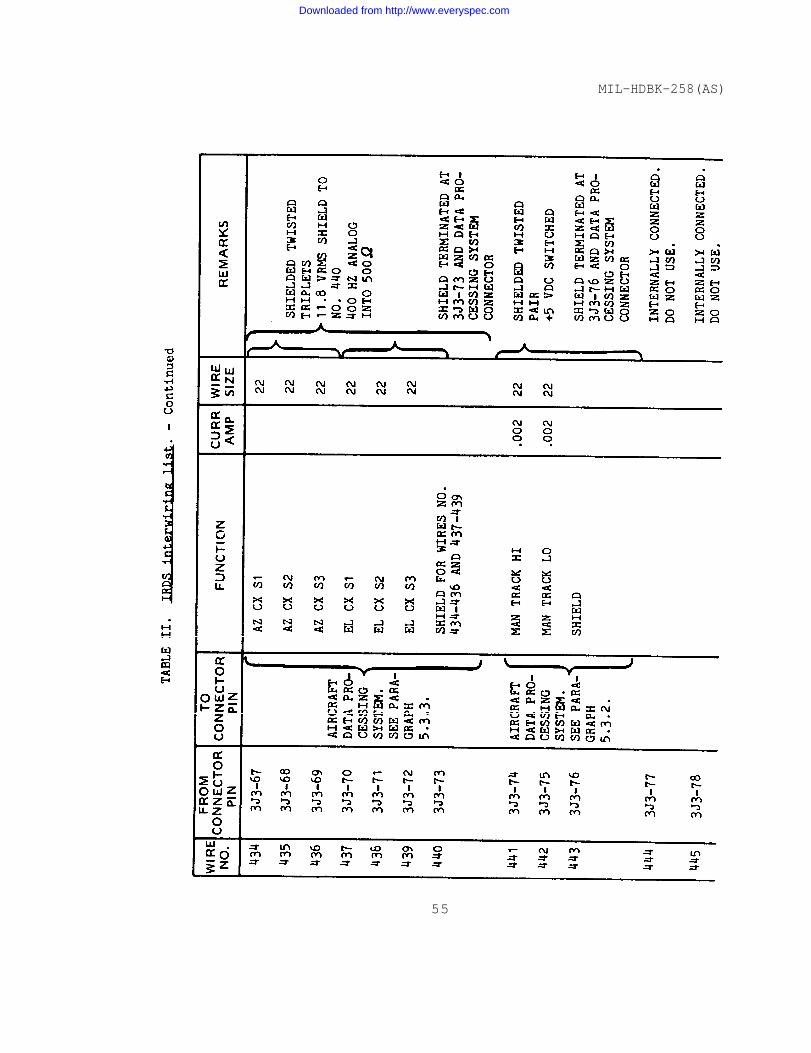
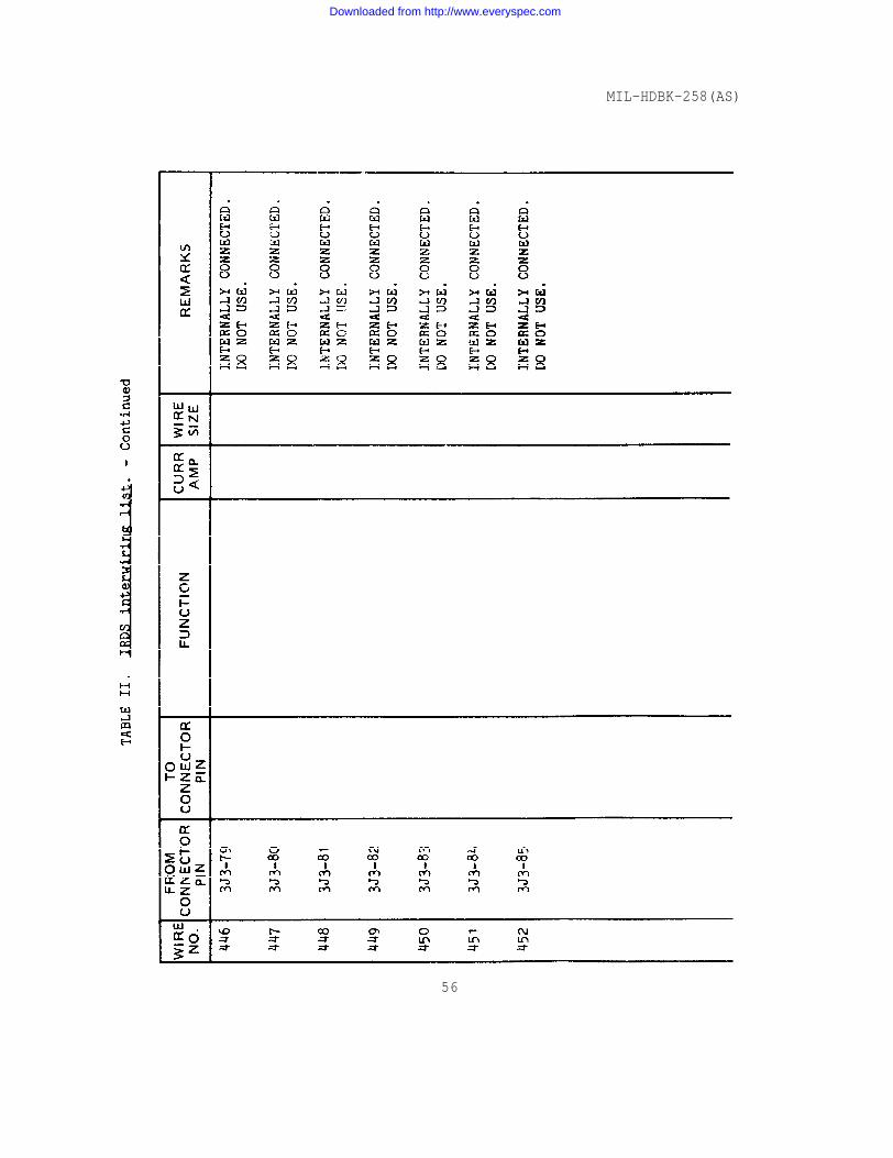
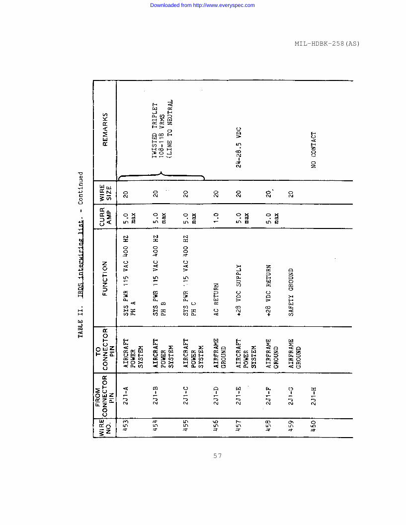
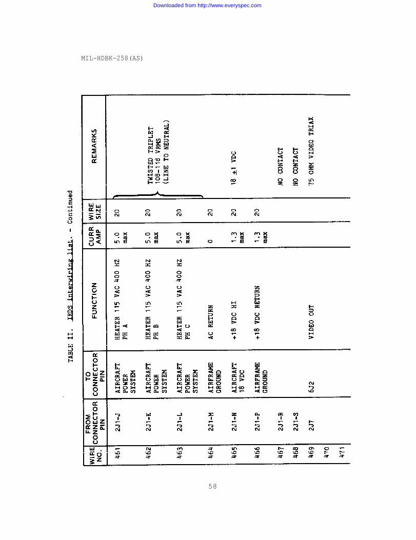
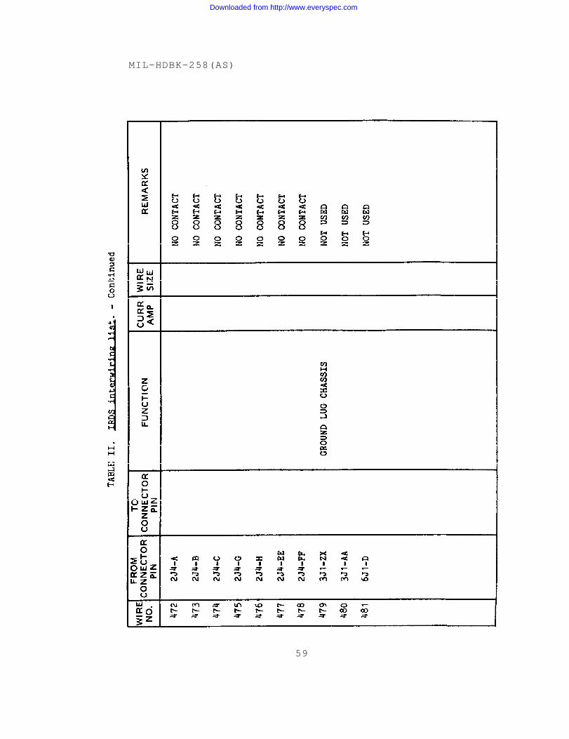
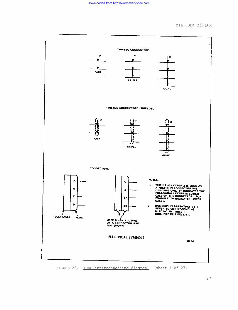
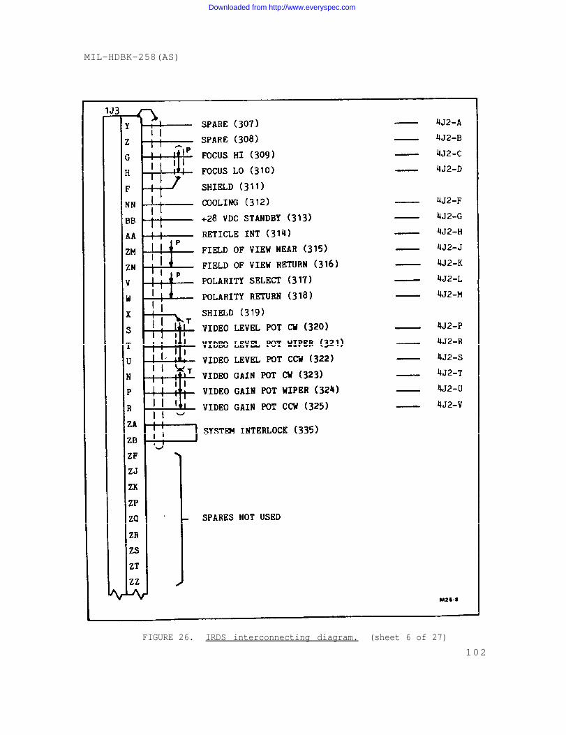
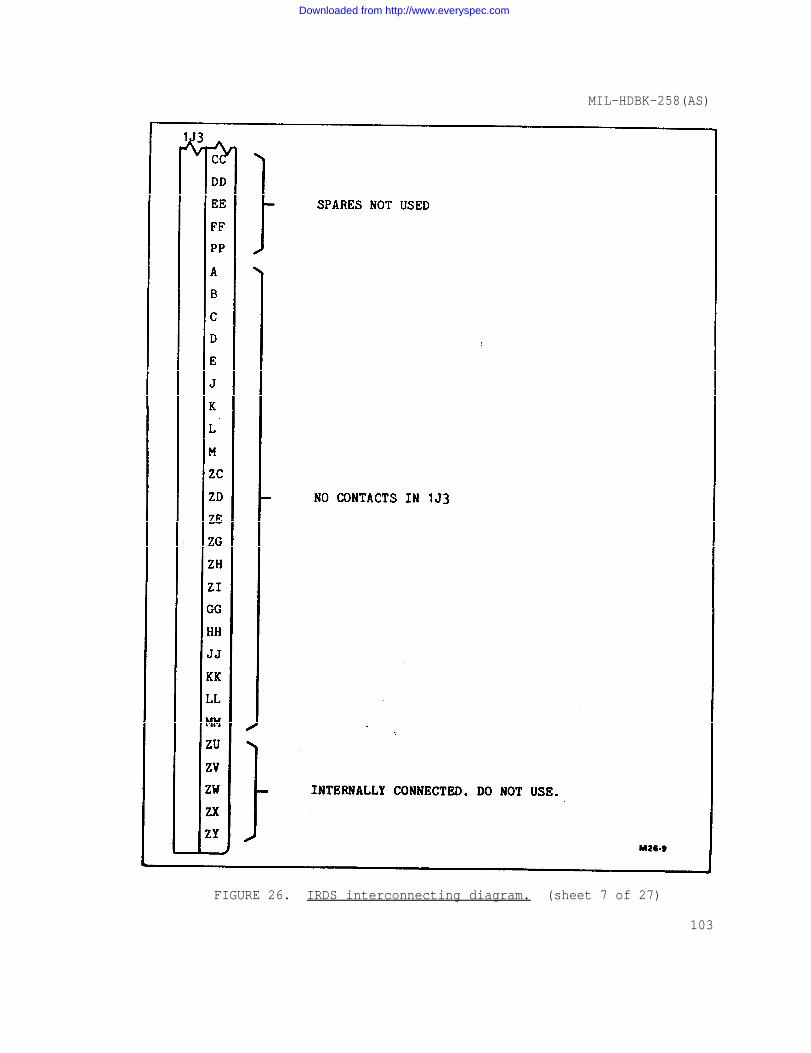
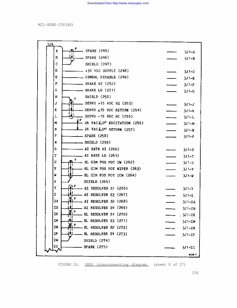
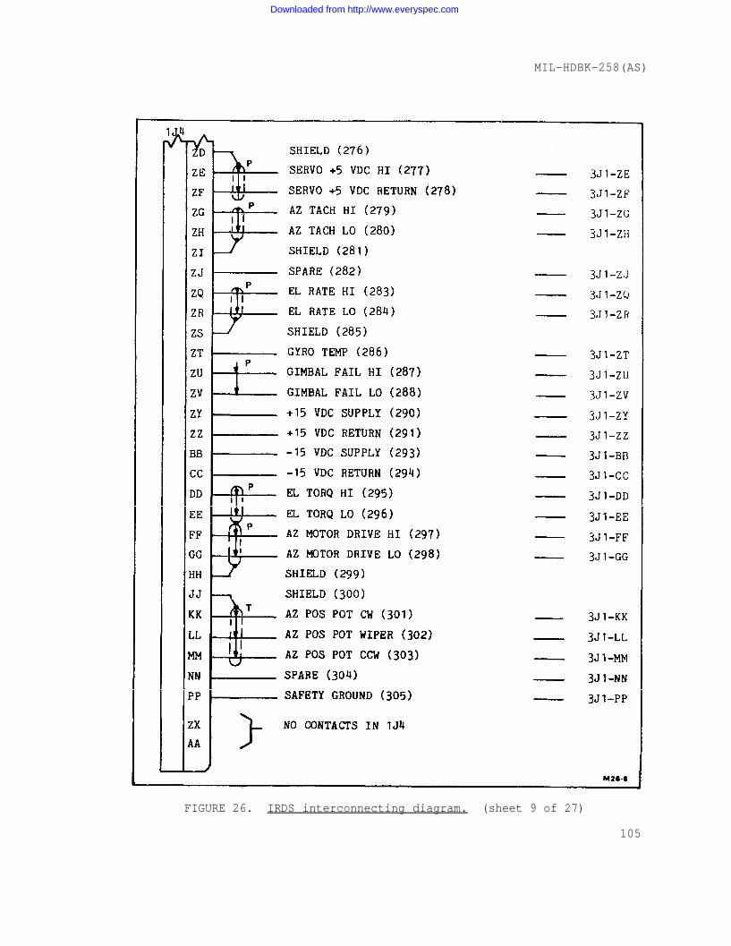
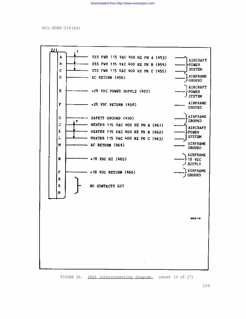
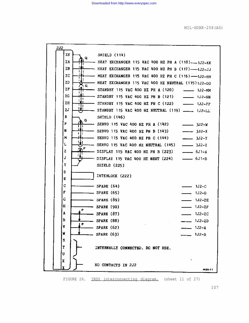
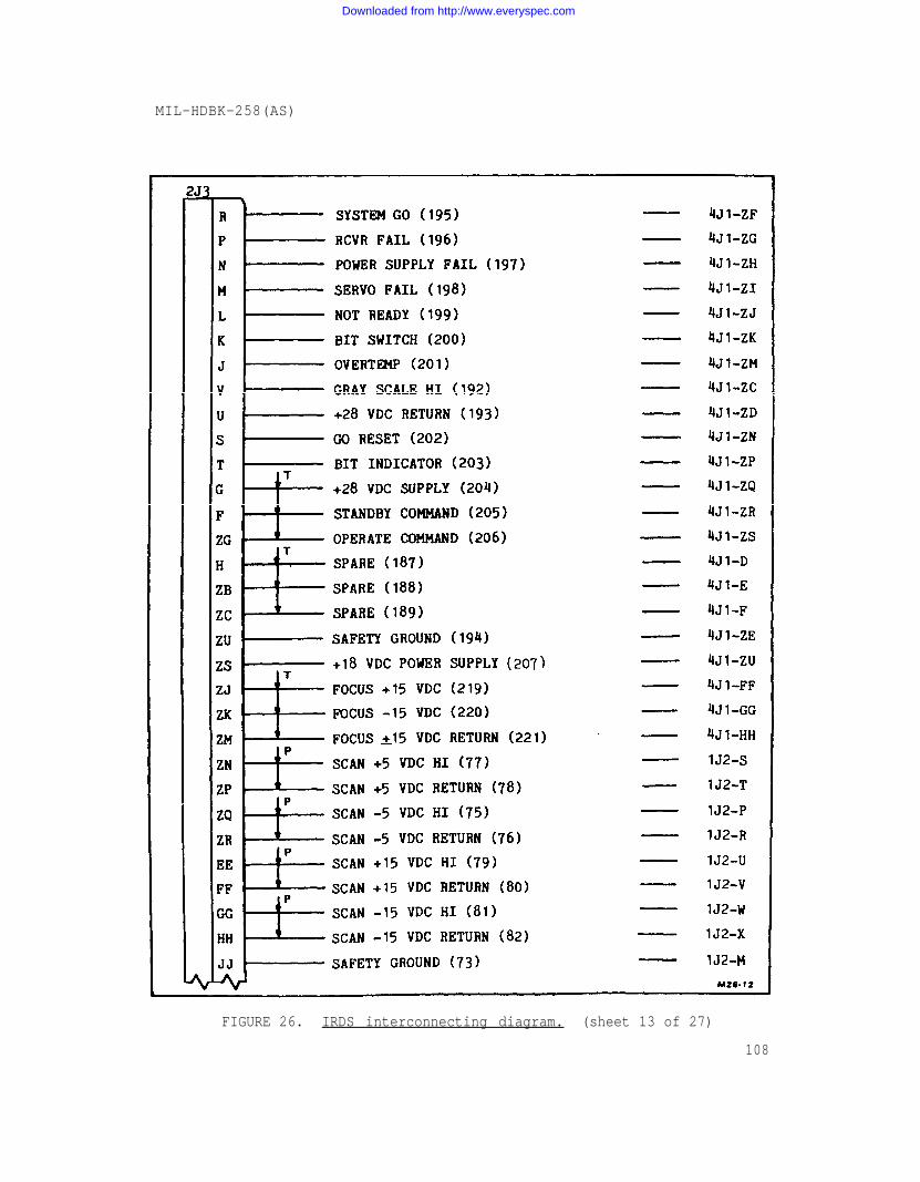
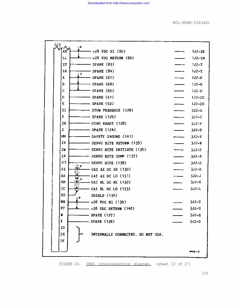
5.2.4 Cabling details. Detailed cabling information, includingconnector pin assignments, and conductor signal function for the IRDSand associated aircraft subsystem interconnections (illustrated infigure 10) is presented in an interwiring listing (table II) on pages23 through 59. This listing provides the point-to-point wiringrequirements between IRDS WRA'S and between IRDS and associated air-craft subsystems. The wiring data is applicable for any IRDSinstallation and does not identify wire segments peculiar to aparticular installation.
5.2.5 Ground/bonding. The ground/bonding practices employed in theinstallation of IRDS electronic circuits in the aircraft shall be in
17
Downloaded from http://www.everyspec.com
MIL-HDBK-258(AS)
accordance with requirements of WR-101 Part I and as qualified herein.IRDS grounding, bonding of cable chassis connectors to IRDS WRA's andpreparation of IRDS WRA metallic mating surfaces, for bonding, whereapplicable, shall be in accordance with WR-101 Part I.
5.2.5.1 Aircraft interconnecting cables. All interconnecting cablesbetween the receiver-converter WRA and other IRDS WRA's and between thereceiver-converter WRA and other aircraft circuits shall include anoverall tight braid shield which will be adequately terminated on theappropriate back-shell of each connector. The overall shield shall notbe interconnected through connector pins. Conductive "Y" or "T" trans-itions or comparable components shall be used at cable splits to insurethat no discontinuities in the overall shield will occur in branchedcables.
5.2.6 Video characteristics. Independent and essentially identicalvideo output signals are provided at each of three output connectors onthe power supply/video converter WRA (2J7, 2J8, 2J9). Each output issingle ended and capable of driving a properly matched 75 ohm videoline. TV and timing and amplitude format of the video signals is inaccordance with EIA RS-343-A, 4:3 aspect ratio, 875 horizontal linerate at 30 frames/see, with 2:1 interlace. The output connectors aretriaxial type (DAGE 2677-l). One video output, (2J7), is connected tothe video indicator WRA (6J2) via 75 ohm triaxial transmission line(Raychem 7524D511 or equivalent). Two video outputs (2J8, 2J9) arespares and provided as Inputs to a GFE conventional video recording/playback unit, a GFE auxiliary display unit or a GFE data link unit.Connections between the video output connectors of the power supply andthe auxiliary GFE shall be as described for the video indicatorinterface.
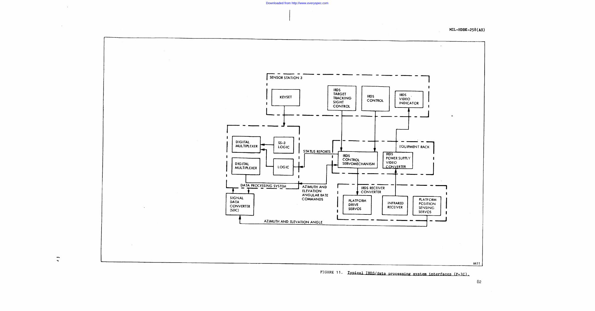
5.3 AN/AAS-36 data system interfaces. The IRDS provides data inter-faces with aircraft data processing systems such as (for P-3C installa-tions) the AN/ASQ-114 Digital Computer/AN/AYA-8 Data Analysis Program-ming group and the CV-2461 A/A Signal Data Converter. Figure 11 is afunctional illustration of a typical (P-3C) IRDS/aircraft data process-ing system interface configuration.
5.3.1 AN/AAS-36 data processing system interface (P-3C). In theCPTR TRK mode of operation, the IRDS will receive rate commands fromthe P-3 computer via the digital output multiplexer (DOM) channel 14 oflogic unit 1 (LU-1) of data analysis programming group AN/AYA-8. Azi-muth and elevation gimbal rate signals will be provided to the IRDS viaa one way digital data transfer in accordance with the following:
a. Computer program initiates a normal Output buffer for thechannel assigned to the DOM.
18
Downloaded from http://www.everyspec.com
MIL-HDBK-258(AS)
b. The DOM sets the output data request (ODR) line indicatingit is in a condition to accept data.
c. The CP-901 1/0 subunit detects the ODR and at its conven-ience places 12 data bits and 4 address bits (identifies)peripheral to accept data) on 16 computer data lines.
d. The DOM transmits the 12 data bits to each peripheralbeing serviced by the assigned computer channel.
e. The computer sets the output acknowledge (OA) line indicat-ing data is stable and ready for sampling.
f. The DOM decodes the address bits and sends the OA to theapplicable peripheral.
g. The peripheral sample data.
h. Computer drops to OA to DOM.
i. DOM drops the OA to peripheral.
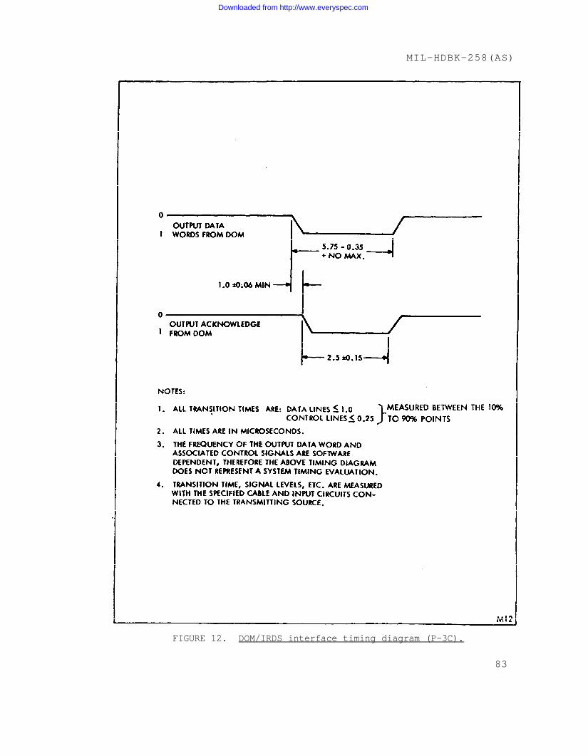
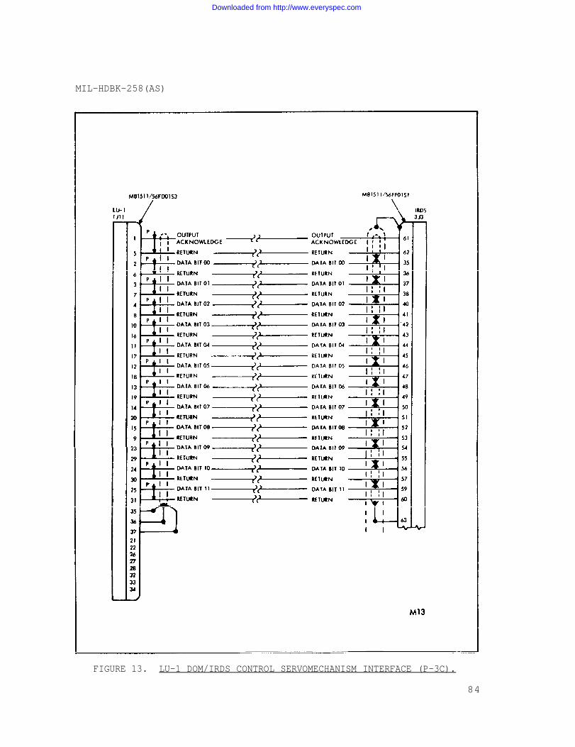
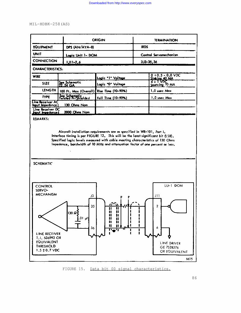
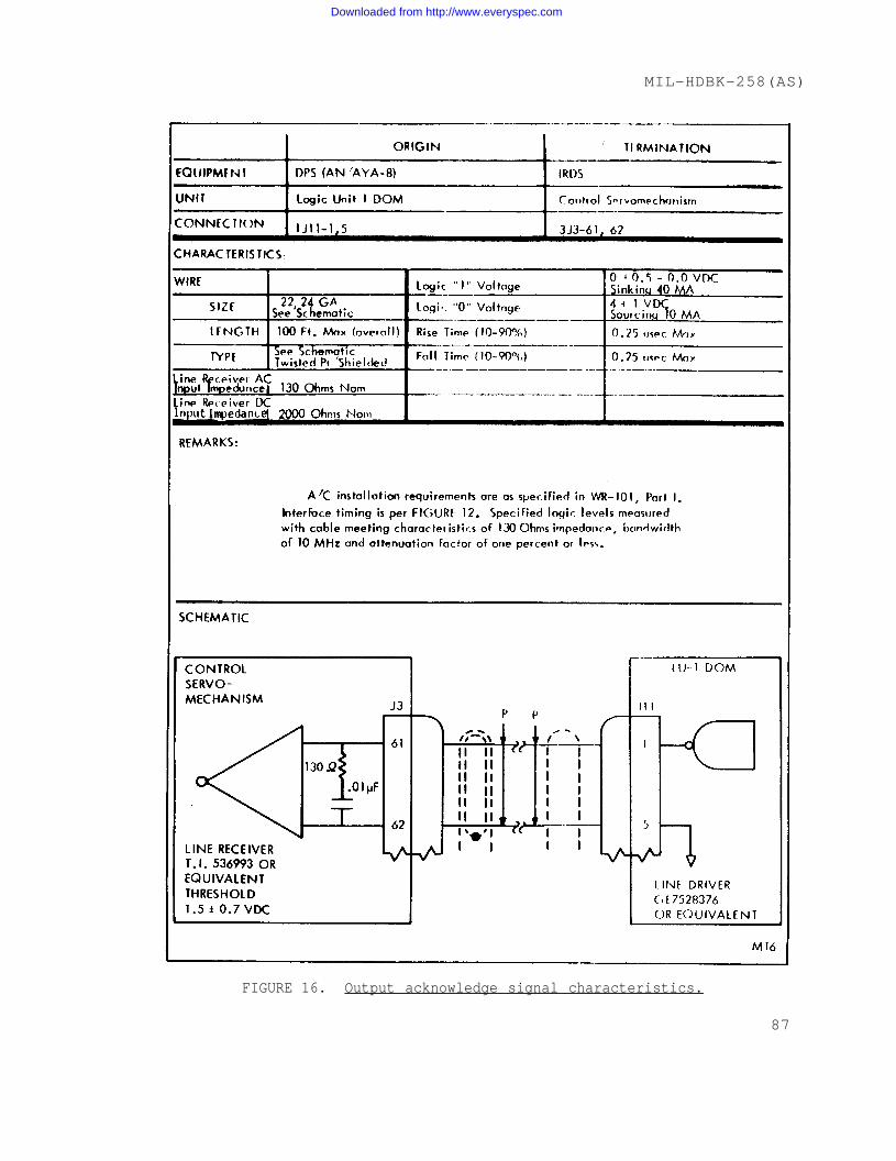
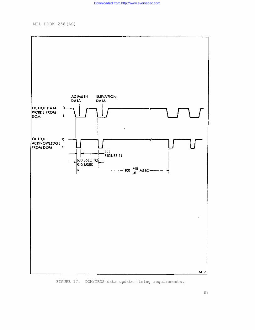
The data lines to peripheral will be stable during the period whenthe OA is active (logic ‘1”) in accordance with the timing diagram pre-sented in figure 12. Overall interface of LU-1 DOM channel 14 withIRDS control, servomechanism unit is illustrated in figure 13.Detailed electrical and mechanical Information for individual dataline and the output acknowledge control line between LU-1 and IRDScontrol servomechanism unit is provided in figures 14 through 16.Logic voltage levels, transition times and interface timing require-ments specified shall exist at the line driver output circuit terminalswith the specified maximum cable length and circuit loads connected.
5.3.1.1 Data update timing requirements. System design assumes ‘hatthe computer will supply data updates (azimuth and elevation angle ratecommands) at approximately a 10 Hz rate. To discriminate between dataupdates and between the first (AZ) and second (EL) words of dataupdates, the IRDS control servomechanism imposes the following timingrequirements upon data from the computer (see figure 17).
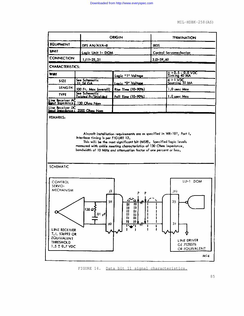
1/ Electrical and mechanical interface details for data bits 00 and 11,LSB and MSB respectively, is provided. Details for data bits 01through 10 are identical with the exception of connector pinassignment, which can be obtained from figure 13.
19
Downloaded from http://www.everyspec.com
MIL-HDBK-258(AS)
a. In general a data word from the computer is interpretedas the first word of a data update unless timing require-ment b., below is satisfied.
b. A word is recognized as the second word of an updateonly if it is received within 5 milliseconds of aprevious word that was recognized as the first word of adata update.
c. When the control, servomechanism has both words of adata update, it uses that data to change the platformcontrol signals and prepares to accept new data from thecomputer. The first word of a new data update canfollow the second word of the previous data update by aslittle as 0.1 millisecond. AS shown by figure 17, thistime interval would ordinarily be In the range of 95 to110 milliseconds ( 10 Hz). Response to data ratesgreater than 10 Hz will be limited by single pole filter-ing with a time constant of 0.1 second.
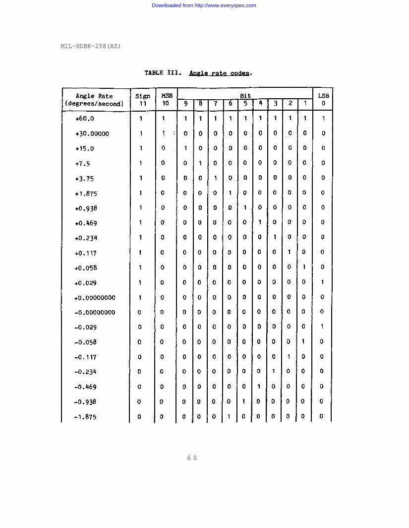
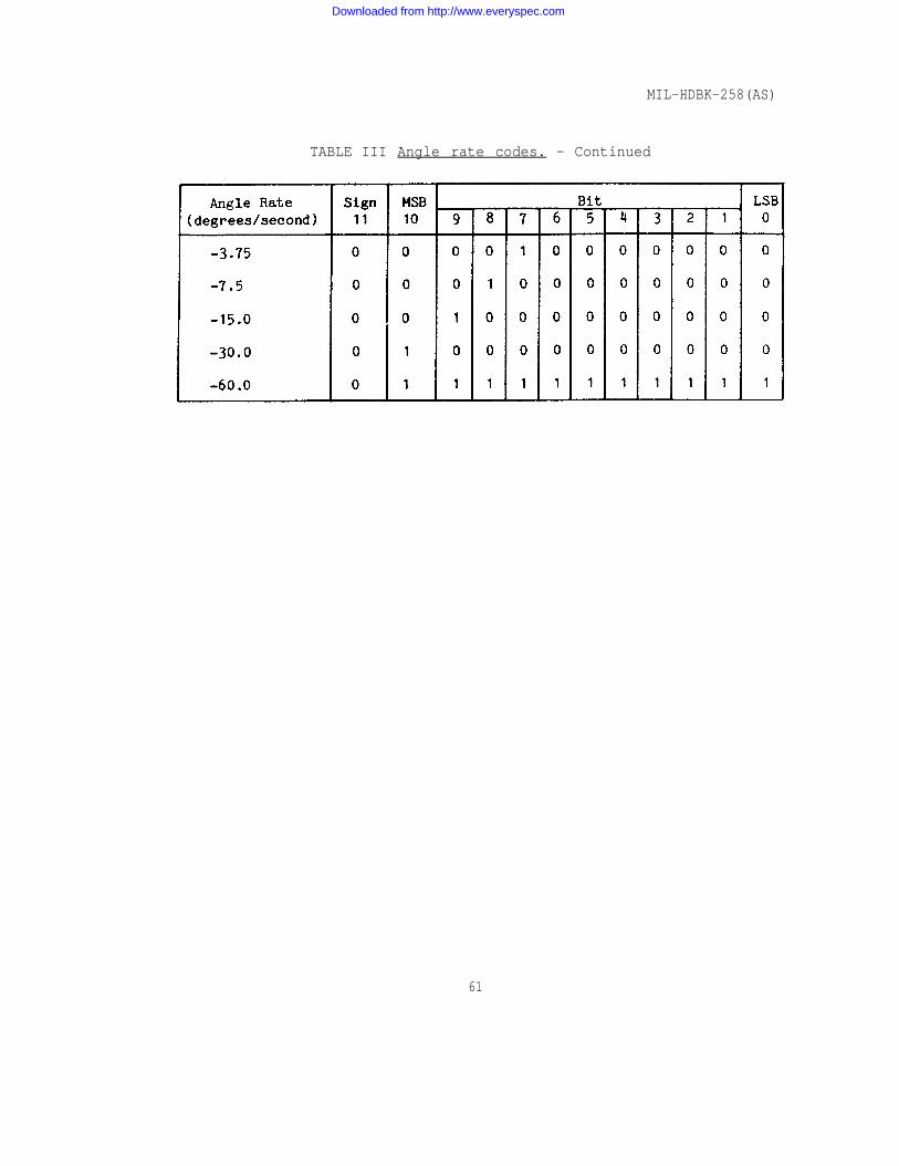
5.3.1.2 Data bit identification. The angle rate commands shall bein sign-magnitude format as shown in table III.convention is
a.
b.
as follows:
Azimuth - when viewed from above, line looking forward shall be 0°,negative angles CCW.
The sign (bit 11)
the aircraft center-positive angles CW and
Elevation - when viewed from the cockpit, lookingforward (parallel to aircraft centerline) shall be O°,positive angles up and negative angles down.
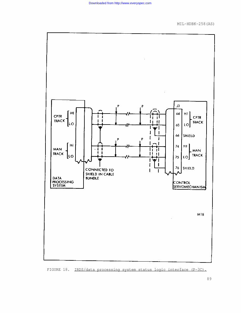
5.3.2 AN/AAS-36 data processing system status logic interface. TheIRDS control servomechanism unit will provide two status signals to thedata processing system. A typical (P-3C) status logic interface of thecontrol servomechanism unit with the data processing system ispresented in figure 18. Detailed electrical and mechanical informationfor the individual status signals is presented in figures 19 and 20.Voltage levels specified shall exist across the line driver outputcircuit terminals with the specified maximum cable lengths and circuitloads connected.
5.3.2.1 IRDS status logic signals. The two status signals suppliedby the IRDS to the aircraft computer are:
a. Computer track - informs computer that IRDS mode selectswitch is in computer track position and IRDS equipmentis not performing built-in test (BIT).
20
Downloaded from http://www.everyspec.com
MIL-HDBK-258(AS)
b. Manual track override - informs computer that thetrigger of the target tracking sight control isdepressed, i.e., subsystem is in manual track mode.
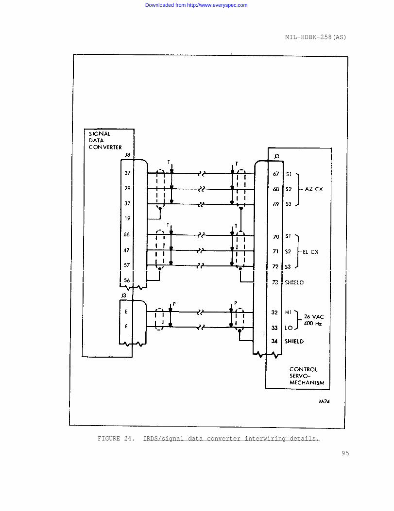
5.3.3 AN/AAS-36 synchro data interface. The IRS control servo-mechanism unit will provide azimuth and elevation gimbal positionreadout signals to the aircraft data processing systems, in synchroform. The gimbal position signals will utilize 11.8 V, 400 Hz, 3 wiresynchro format compatible with synchro to digital converters such asthe CV-2461 A/A. Typical (P-3C) electrical and mechanical synchrointerface details are presented in figures 21 and 22.
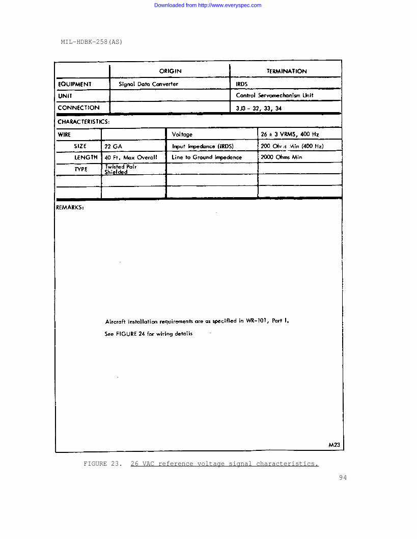
5.3.3.1 Synchro excitation reference. The aircraft data processingsystem must provide a 26 V, 400 Hz excitation signal for the azimuthand elevation position synchro transmitters in the IRDS receiver-con-verter, via the control servomechanism unit. Detailed electrical andmechanical interface information for the synchro reference signal ispresented in figure 23. Typical (P-3C) overall wiring details for theIRDS synchro signals and the 26 VAC reference is provided in figure 24.
5.3.3.2 Electrical zero. The following method can be implemented toprovide a coarse electrical zero verification. This is not an accuratetest, but will determine which of two possible null positions corres-pond to electrical zero.
All signals necessary for this determination are present on 3J3, thecontrol-servomechanism WRA to aircraft interface connector. They areR1 (26 VAC 400 Hz LO), R2 (26 VAC 400 Hz HI), AS1, AS2, AS3 (azimuthsynchro S1, S2 and S3) and ES1, ES2, ES3 (elevation synchro S1, S2 andS3). Detail pin connections are provided in figure 24. The AN/AAS-36must be energized through 3J3. A means of break-out of these signalswill be required. An oscilloscope with two vertical input channelswill be used with horizontal time base synchronized to channel 2.Convert R2 to channel 2 vertical input.
Procedures:
a. Initially point the system LOS to approximately boresight. Allcables must be connected for test, but system power (mode switch)may be off.
b. For azimuth axis, connect AS1 and AS3 together, and to channel 1of the scope. Connect AS2 to R1 together and connect to scopereturn - if the proper electrical zero has been chosen, the twowaveforms displayed will be approximately in time phase. Ifincorrect electrical zero has been chosen, the two waveforms willbe approximately 180° out of time phase.
21
Downloaded from http://www.everyspec.com
MIL-HDBK-258(AS)
c. For elevation axis, repeat b. except use ES1, ES2 and ES3 insteadof AS1, AS2 and AS3.
5.4 AN/AAS-36 electrical interlocks.
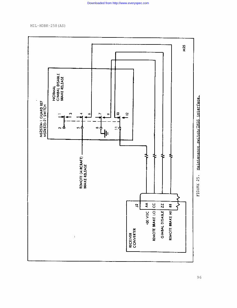
5.4.1 AN/AAS 36 maintenance switch. The IRDS receiver-converterwill interface with a remote receiver-converter maintenance switch.The maintenance switch will be a 3 position device which establishesthe following operating conditions:
a. Upper position (normal) - normal receiver converteroperation
b. Center position (gimbal disable) - normal receiver--
converter operation except power (+30 VDC) is removed fromthe gimbal drive mechanism.
c. Lower position (brake release) - same as center Positionexcept, gimbal brake release connections are made throughthe maintenance switch to the receiver-converter. Brakerelease high (Hi), +28 VDC (when enabled) and brakerelease low (Lo), a ground.
Figure 25 details the overall interfaces of the receiver converterand the q aintenance switch.
6. COGNIZANCE
6.1 This handbook is under the engineering cognizance of AIR-549332.
Preparing Activity-NAVY ASProject No. 5855-0028
22
Downloaded from http://www.everyspec.com
MIL-HDBK-258(AS)
23
Downloaded from http://www.everyspec.com
MIL-HDBK-258(AS)
24
Downloaded from http://www.everyspec.com
MIL-HDBK-258(AS)
25
Downloaded from http://www.everyspec.com
MIL-HDBK-258(AS)
26
Downloaded from http://www.everyspec.com
MIL-HDBK-258(AS)
27
Downloaded from http://www.everyspec.com
MIL-HDBK-258(AS)
28
Downloaded from http://www.everyspec.com
MIL-HDBK-258(AS)
29
Downloaded from http://www.everyspec.com
MIL-HDBK-258(AS)
3 0
Downloaded from http://www.everyspec.com
MIL-HDBK-258(AS)
3 1
Downloaded from http://www.everyspec.com
MIL-HDBK-258(AS)
32
Downloaded from http://www.everyspec.com
MIL-HDBK-258(AS)
33
Downloaded from http://www.everyspec.com
MIL-HDBK-258(AS)
34
Downloaded from http://www.everyspec.com
MIL-HDBK-258(AS)
3 5
Downloaded from http://www.everyspec.com
MIL-HDBK-258(AS)
36
Downloaded from http://www.everyspec.com
MIL-HDBK-258(AS)
3 7
Downloaded from http://www.everyspec.com
MIL-HDBK-258(AS)
38
Downloaded from http://www.everyspec.com
MIL-HDBK-258(AS)
39
Downloaded from http://www.everyspec.com
MIL-HDBK-258(AS)
40
Downloaded from http://www.everyspec.com
MIL-HDBK-258(AS)
4 1
Downloaded from http://www.everyspec.com
MIL-HDBK-258(AS)
42
Downloaded from http://www.everyspec.com
MIL-HDBK-258(AS)
43
Downloaded from http://www.everyspec.com
MIL-HDBK-258(AS)
44
Downloaded from http://www.everyspec.com
MIL-HDBK-258(AS)
4 5
Downloaded from http://www.everyspec.com
MIL-HDBK-258(AS)
46
Downloaded from http://www.everyspec.com
MIL-HDBK-258(AS)
47
Downloaded from http://www.everyspec.com
MIL-HDBK-258(AS)
48
Downloaded from http://www.everyspec.com
MIL-HDBK-258(AS)
49
Downloaded from http://www.everyspec.com
MIL-HDBK-258(AS)
50
Downloaded from http://www.everyspec.com
MIL-HDBK-258(AS)
5 1
Downloaded from http://www.everyspec.com
MIL-HDBK-258(AS)
52
Downloaded from http://www.everyspec.com
MIL-HDBK-258(AS)
53
Downloaded from http://www.everyspec.com
MIL-HDBK-258(AS)
54
Downloaded from http://www.everyspec.com
MIL-HDBK-258(AS)
55
Downloaded from http://www.everyspec.com
MIL-HDBK-258(AS)
56
Downloaded from http://www.everyspec.com
MIL-HDBK-258(AS)
57
Downloaded from http://www.everyspec.com
MIL-HDBK-258(AS)
58
Downloaded from http://www.everyspec.com
MIL-HDBK-258(AS)
59
Downloaded from http://www.everyspec.com
MIL-HDBK-258(AS)
6 0
Downloaded from http://www.everyspec.com
MIL-HDBK-258(AS)
TABLE III Angle rate codes. - Continued
61
Downloaded from http://www.everyspec.com
Downloaded from http://www.everyspec.com
Downloaded from http://www.everyspec.com
Downloaded from http://www.everyspec.com
Downloaded from http://www.everyspec.com
MIL-HDBK-258(AS)
FIGURE 1. Receiver converter, outline drawing. (sheet 5 of 5)
66
Downloaded from http://www.everyspec.com
Downloaded from http://www.everyspec.com
Downloaded from http://www.everyspec.com
Downloaded from http://www.everyspec.com
Downloaded from http://www.everyspec.com
Downloaded from http://www.everyspec.com
Downloaded from http://www.everyspec.com
Downloaded from http://www.everyspec.com
Downloaded from http://www.everyspec.com
Downloaded from http://www.everyspec.com
Downloaded from http://www.everyspec.com
Downloaded from http://www.everyspec.com
Downloaded from http://www.everyspec.com
MIL-HDBK-258(AS)
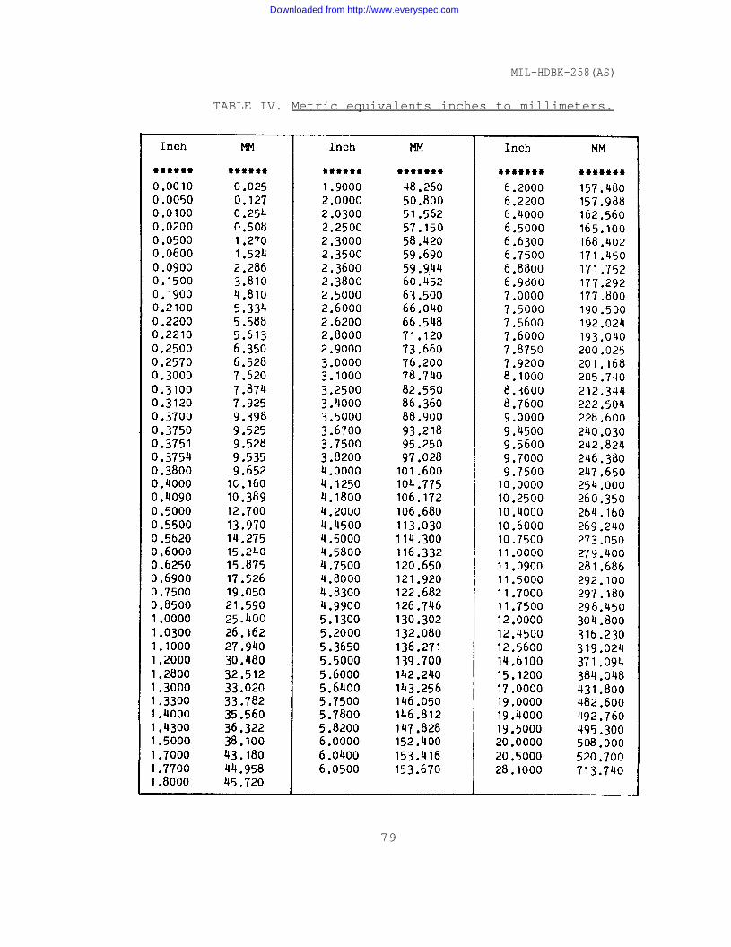
TABLE IV. Metric equivalents inches to millimeters.
79
Downloaded from http://www.everyspec.com
Downloaded from http://www.everyspec.com
Downloaded from http://www.everyspec.com
Downloaded from http://www.everyspec.com

Downloaded from http://www.everyspec.com

Downloaded from http://www.everyspec.com
MIL-HDBK-258(AS)
FIGURE 12. DOM/IRDS interface timing diagram (P-3C).
83
Downloaded from http://www.everyspec.com
MIL-HDBK-258(AS)
FIGURE 13. LU-1 DOM/IRDS CONTROL SERVOMECHANISM INTERFACE (P-3C).
84
Downloaded from http://www.everyspec.com
MIL-HDBK-258(AS)
FIGURE 14. Data bit 11 signal characteristics.
85
Downloaded from http://www.everyspec.com
MIL-HDBK-258(AS)
FIGURE 15. Data bit 00 signal characteristics.
86
Downloaded from http://www.everyspec.com
MIL-HDBK-258(AS)
FIGURE 16. Output acknowledge signal characteristics.
87
Downloaded from http://www.everyspec.com
MIL-HDBK-258(AS)
FIGURE 17. DOM/IRDS data update timing requirements.
88
Downloaded from http://www.everyspec.com
MIL-HDBK-258(AS)
FIGURE 18. IRDS/data processing system status logic interface (P-3C).
89
Downloaded from http://www.everyspec.com
MIL-HDBK-258(AS)
FIGURE 19. Computer track signal characteristics.
9 0
Downloaded from http://www.everyspec.com
MIL-HDBK-258(AS)
FIGURE 20. Manual track override signal characteristics.
91
Downloaded from http://www.everyspec.com
MIL-HDBK-258(AS)
FIGURE 21. IRDS az position signal characteristics.
92
Downloaded from http://www.everyspec.com
MIL-HDBK-258(AS)
Figure 22. IRDS el position signal characteristics.
93
Downloaded from http://www.everyspec.com
MIL-HDBK-258(AS)
FIGURE 23. 26 VAC reference voltage signal characteristics.
94
Downloaded from http://www.everyspec.com
MIL-HDBK-258(AS)
FIGURE 24. IRDS/signal data converter interwiring details.
95
Downloaded from http://www.everyspec.com
MIL-HDBK-258(AS)
96
Downloaded from http://www.everyspec.com
MIL-HDBK-258(AS)
FIGURE 26. IRDS interconnecting diagram. (sheet 1 of 27)
97
Downloaded from http://www.everyspec.com
MIL-HDBK-258(AS)
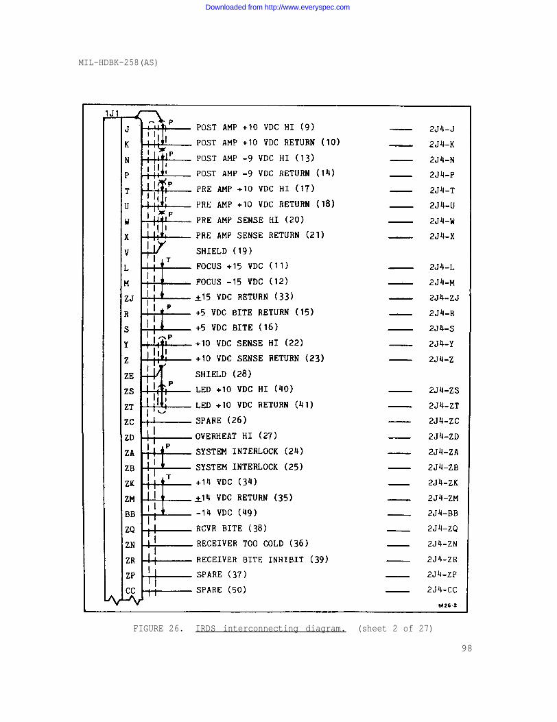
FIGURE 26. IRDS interconnecting diagram. (sheet 2 of 27)
98
Downloaded from http://www.everyspec.com
MIL-HDBK-258(AS)
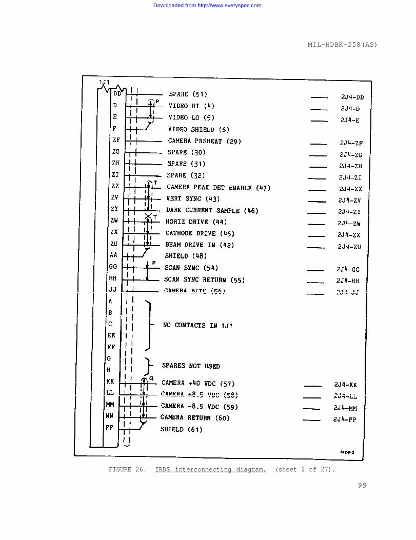
FIGURE 26. IRDS interconnecting diagram. (sheet 2 of 27).
99
Downloaded from http://www.everyspec.com
MIL-HDBK-258(AS)
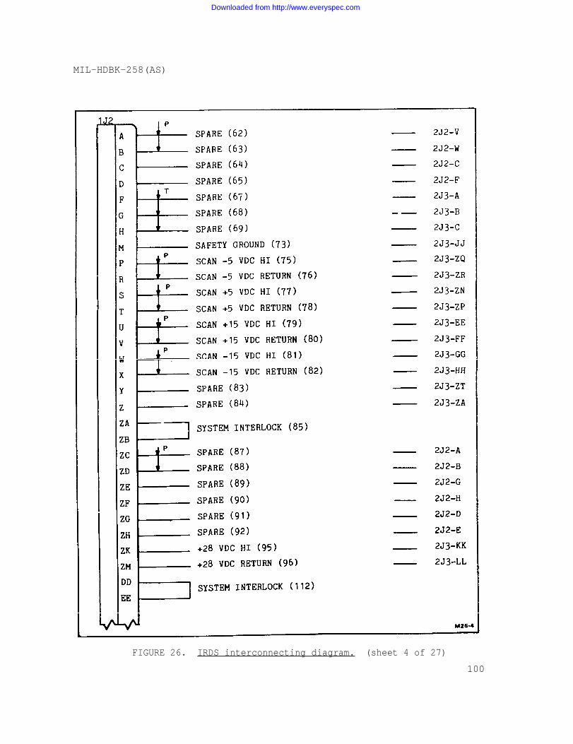
FIGURE 26. IRDS interconnecting diagram. (sheet 4 of 27)
100
Downloaded from http://www.everyspec.com
MIL-HDBK-258(AS)
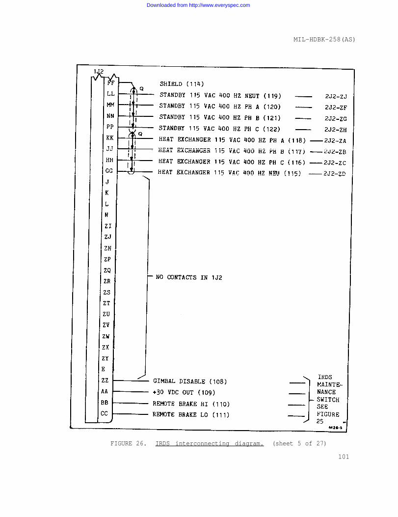
FIGURE 26. IRDS interconnecting diagram. (sheet 5 of 27)
101
Downloaded from http://www.everyspec.com
MIL-HDBK-258(AS)
FIGURE 26. IRDS interconnecting diagram. (sheet 6 of 27)
102
Downloaded from http://www.everyspec.com
MIL-HDBK-258(AS)
FIGURE 26. IRDS interconnecting diagram. (sheet 7 of 27)
103
Downloaded from http://www.everyspec.com
MIL-HDBK-258(AS)
FIGURE 26. IRDS interconnecting diagram. (sheet 8 of 27)
104
Downloaded from http://www.everyspec.com
MIL-HDBK-258(AS)
FIGURE 26. IRDS interconnecting diagram. (sheet 9 of 27)
105
Downloaded from http://www.everyspec.com
MIL-HDBK-258(AS)
FIGURE 26. IRDS interconnecting diagram. (sheet 10 of 27)
106
Downloaded from http://www.everyspec.com
MIL-HDBK-258(AS)
FIGURE 26. IRDS interconnecting diagram. (sheet 11 of 27)
107
Downloaded from http://www.everyspec.com
MIL-HDBK-258(AS)
FIGURE 26. IRDS interconnecting diagram. (sheet 13 of 27)
108
Downloaded from http://www.everyspec.com
MIL-HDBK-258(AS)
FIGURE 26. IRDS interconnecting diagram. (sheet 13 of 27)
109
Downloaded from http://www.everyspec.com
MIL-HDBK-258(AS)
FIGURE 26. IRDS interconnecting diagram. (sheet 14 of 27)110
Downloaded from http://www.everyspec.com
MIL-HDBK-258(AS)
FIGURE 26. IRDS interconnecting diagram. (sheet 15 of 27)
111
Downloaded from http://www.everyspec.com
MIL-HDBK-258(AS)
FIGURE 26. IRDS interconnecting diagram. (sheet 16 of 27)
112
Downloaded from http://www.everyspec.com
MIL-HDBK-258(AS)
FIGURE 26. IRDS interconnecting diagram. (sheet 17 of 27)
113
Downloaded from http://www.everyspec.com
MIL-HDBK-258(AS)
FIGURE 26. IRDS interconnecting diagram. (sheet 18 of 27)
114
Downloaded from http://www.everyspec.com
MIL-HDBK-258(AS)
FIGURE 26. IRDS interconnecting diagram. (sheet 19 of 27)
115
Downloaded from http://www.everyspec.com
MIL-HDBK-258(AS)
FIGURE 26. IRDS interconnecting diagram. (sheet 20 of 27)
116
Downloaded from http://www.everyspec.com

MIL-HDBK-258(AS)
FIGURE 26. IRDS interconnecting diagram. (sheet 21 of 27)
117
Downloaded from http://www.everyspec.com
MIL-HDBK-258(AS)
FIGURE 26. IRDS interconnecting diagram. (sheet 22 of 27)
118
Downloaded from http://www.everyspec.com
MIL-HDBK-258(AS)
FIGURE 26. IRDS interconnecting diagram. (sheet 23 of 27)
119
Downloaded from http://www.everyspec.com
MIL-HDBK-258(AS)
FIGURE 26. IRDS interconnecting diagram. (sheet 24 of 27)
120
Downloaded from http://www.everyspec.com

MIL-HDBK-258(AS)
FIGURE 26. IRDS interconnecting diagram. (sheet 25 of 27)
121
Downloaded from http://www.everyspec.com
MIL-HDBK-258(AS)
FIGURE 26. IRDS interconnecting diagram. (sheet 27 of 27)122
Downloaded from http://www.everyspec.com
MIL-HDBK-258(AS)
FIGURE 26. IRDS interconnecting diagram. (sheet 27 of 27)
123
Downloaded from http://www.everyspec.com

Downloaded from http://www.everyspec.com
Downloaded from http://www.everyspec.com
Downloaded from http://www.everyspec.com
MIL–HDBK–258(AS)NOTICE 124 October 1991
MILITARY HANDBOOK
INTERFACE CONTROL DOCUMENTFOR INFRARED DETECTING SET AN/AAS-36
MIL–HDBK–258(AS), dated 3 August 1979, has been reviewed and determined to be validfor use in acquisition.
Preparing activity:Navy – AS
AMSC N/A FSC 5855DISTRIBUTION STATEMENT A. Approved for public release; distribution is unlimited.
Downloaded from http://www.everyspec.com

Downloaded from http://www.everyspec.com