milestone xprotect professional 7.0; administrator's manual · milestone xprotect professional...
TRANSCRIPT
XProtect™ Milestone
Professional 7.0 Administrator ’s Manual
Milestone XProtect Professional 7.0; Administrator’s Manual
www.milestonesys.com Target Audience
Target Audience for this Document
This document covers Milestone XProtect Professional from a surveillance system administrator’s perspective. It is solely aimed at XProtect Professional system administrators, and administrator
rights are likely to be required in order to be able to access the majority of features described in this document.
This document provides detailed descriptions of XProtect Professional system administration features. It furthermore provides a large number of targeted ―how-to‖ examples, guiding administrators through completing configuration and administration tasks in XProtect Professional.
This document contains very limited end-user related documentation. Administrators requiring information about end-user related client applications should refer to the targeted manuals available on the XProtect Professional software DVD as well as from www.milestonesys.com. Users who do not have surveillance system administrator responsibilities—such as users of the Viewer, Remote Client, Smart Client, PDA Client, or Matrix Monitor—will find that this manual is not of relevance to them. Such users will be able to find information targeted at their needs in the
separate manuals available on the XProtect Professional software DVD as well as from www.milestonesys.com.
XPP70-am-3(a3)-081110
Milestone XProtect Professional 7.0; Administrator’s Manual
www.milestonesys.com Copyright, Trademarks …
Copyright, Trademarks & Important
Information
Copyright © 2010 Milestone Systems A/S.
Trademarks XProtect is a registered trademark of Milestone Systems A/S. Microsoft® and Windows® are registered trademarks of Microsoft Corporation.
All other trademarks mentioned in this document are trademarks of their respective owners.
Disclaimer This document is intended for general information purposes only, and due care has been taken in
its preparation.
Any risk arising from the use of this information rests with the recipient, and nothing herein should be construed as constituting any kind of warranty. Milestone Systems A/S reserve the right to make adjustments without prior notification. All names of people and organizations used in this document’s examples are fictitious. Any resemblance to any actual organization or person, living or dead, is purely coincidental and
unintended.
Milestone XProtect Professional 7.0; Administrator’s Manual
www.milestonesys.com Page 4 Contents
Contents
INTRODUCTION ........................................................ 11
WHAT’S NEW IN XPROTECT PROFESSIONAL 7.0....... 12
SYSTEM & REQUIREMENTS ....................................... 13
Minimum System Requirements ......................................................... 13
Administrator Rights .......................................................................... 16
Important Port Numbers .................................................................... 16
Virus Scanning .................................................................................... 17
Time Server ........................................................................................ 17
INSTALLATION ......................................................... 18
Upgrade from a Previous Version ....................................................... 19
GET YOUR SYSTEM UP AND RUNNING ...................... 21
Access the Management Application ................................................... 23
MANAGEMENT APPLICATION .................................... 24
Password Protection ........................................................................... 24
Apply/Save Configuration Changes .................................................... 24
Change/Reset Behavior ...................................................................... 25
WIZARDS ................................................................. 26
Add Hardware Devices Wizard ............................................................ 26
Express Method .................................................................................. 27
Advanced Method ............................................................................... 29
Manual Method ................................................................................... 32
Milestone XProtect Professional 7.0; Administrator’s Manual
www.milestonesys.com Page 5 Contents
Import from CSV File Method ............................................................... 35
CSV File Format and Requirements ................................................... 35
Configure Video and Recording Wizard ............................................... 38
Video Settings and Preview .................................................................. 38
Online Schedule.................................................................................. 39
Live and Recording Settings (Motion-JPEG Cameras) ............................... 40
Live and Recording Settings (MPEG Cameras) ........................................ 41
Drive Selection ................................................................................... 43
Recording and Archiving Settings .......................................................... 44
Adjust Motion Detection Wizard ......................................................... 45
Exclude Regions ................................................................................. 45
Motion Detection ................................................................................ 45
Configure User Access Wizard ............................................................ 46
Server Access Settings ........................................................................ 47
Basic and Windows Users ..................................................................... 47
Access Summary ................................................................................ 48
Replace Hardware Device Wizard ....................................................... 48
New Hardware Device Information ........................................................ 49
Database Action ................................................................................. 50
LICENSES ................................................................. 52
Import DLKs (Device License Keys) .................................................... 52
Specify a New SLC (Software License Code) ....................................... 52
HARDWARE DEVICES ................................................ 53
Configuration ...................................................................................... 53
Name & Video Channels....................................................................... 53
Network, Device Type & License ........................................................... 53
PTZ Device ........................................................................................ 54
Fisheye.............................................................................................. 55
Use Dedicated Input/Output Devices ................................................. 55
Replace a Hardware Device ................................................................ 56
Delete a Hardware Device ................................................................... 56
Milestone XProtect Professional 7.0; Administrator’s Manual
www.milestonesys.com Page 6 Contents
CAMERAS AND RECORDINGS .................................... 57
General Recording and Storage Configuration .................................... 57
Recording & Archiving Paths ................................................................. 57
Dynamic Path Selection ....................................................................... 59
Video Recording ................................................................................. 60
Manual Recording ............................................................................... 61
Frame Rate – MJPEG ........................................................................... 62
Frame Rate – MPEG ............................................................................ 64
Audio Selection................................................................................... 65
Audio Recording ................................................................................. 66
Storage Information ............................................................................ 67
Camera-specific Configuration ............................................................ 67
Camera ............................................................................................. 67
Frame Rate ........................................................................................ 68
Video ................................................................................................ 69
Audio ................................................................................................ 70
Recording Settings .............................................................................. 70
Recording & Archiving Paths ................................................................. 71
Event Notification ............................................................................... 73
Output .............................................................................................. 73
Motion Detection & Exclude Regions ...................................................... 74
Fisheye.............................................................................................. 76
PTZ Preset Positions ............................................................................ 77
PTZ Patrolling ..................................................................................... 79
Patrolling Profiles ............................................................................ 79
Preset Positions to Use in Patrolling Profiles ........................................ 80
Wait and Transition Timing............................................................... 80
PTZ Scanning ................................................................................. 81
Pause and Resume PTZ Patrolling ..................................................... 81
PTZ on Event ..................................................................................... 82
Configure When Cameras Should Do What ......................................... 82
View Video in Management Application .............................................. 83
Monitor Storage Space Usage ............................................................. 83
Database Resizing .............................................................................. 83
Disable or Delete a Camera ................................................................. 84
Milestone XProtect Professional 7.0; Administrator’s Manual
www.milestonesys.com Page 7 Contents
ARCHIVING .............................................................. 85
Benefits of Archiving .......................................................................... 85
How Archiving Works ......................................................................... 85
Dynamic Path Selection for Archives ..................................................... 86
Archiving Audio .................................................................................. 87
Viewing Archived Recordings ................................................................ 87
Storage Capacity Required for Archiving ................................................ 87
Backing Up Archives ............................................................................ 88
Automatic Response if Running Out of Disk Space .................................. 88
New Database if Archiving Fails ............................................................ 90
Virus Scanning and Archiving ............................................................... 90
Configure Archiving Locations ............................................................ 91
Configure Archiving Schedules ........................................................... 91
AUDIO ...................................................................... 93
Configure Microphones ....................................................................... 93
Configure Speakers ............................................................................. 94
SCHEDULING ............................................................ 95
Configure General Scheduling and Archiving ...................................... 95
Scheduling All Cameras ....................................................................... 95
Scheduling Options ............................................................................. 96
Archiving ........................................................................................... 97
Configure Camera-specific Scheduling ................................................ 97
Online Period ..................................................................................... 98
Speedup ............................................................................................ 99
E-mail Notification ............................................................................ 100
SMS Notification ............................................................................... 100
PTZ Patrolling ................................................................................... 101
E-MAIL AND SMS (MOBILE TEXT) ........................... 103
Configure E-mail Notifications .......................................................... 103
Configure SMS Notifications .............................................................. 105
Milestone XProtect Professional 7.0; Administrator’s Manual
www.milestonesys.com Page 8 Contents
EVENTS, INPUT AND OUTPUT ................................. 107
Configure General Event Handling .................................................... 108
Add a Hardware Input Event ............................................................. 109
Add a Manual Event .......................................................................... 110
Add a Generic Event .......................................................................... 111
Test a Generic Event ......................................................................... 114
Add a Timer Event ............................................................................ 116
Add a Hardware Output .................................................................... 117
Configure Hardware Output on Event ............................................... 118
SERVICES ............................................................... 119
Start and Stop Services .................................................................... 119
CLIENT ACCESS TO SURVEILLANCE SYSTEM ........... 120
Wizard-driven Configuration ............................................................. 120
Advanced Configuration .................................................................... 120
Server Access................................................................................... 120
Local IP Ranges ................................................................................ 121
Language Support & XML Encoding ..................................................... 121
USERS .................................................................... 122
Wizard-driven Configuration ............................................................. 122
Advanced Configuration .................................................................... 122
Add Basic Users ................................................................................ 122
Add Windows Users ........................................................................... 123
Add User Groups .............................................................................. 124
Configure User and Group Rights ........................................................ 124
User and Group Properties ................................................................ 125
LOGGING ................................................................ 128
Configure System, Event, and Audit Logging .................................... 129
Log Integrity Checks ......................................................................... 130
Milestone XProtect Professional 7.0; Administrator’s Manual
www.milestonesys.com Page 9 Contents
CENTRAL ................................................................ 132
MATRIX VIDEO SHARING ....................................... 133
Configure Matrix for Manual Video Sharing ....................................... 133
Configure Matrix for Automatic Video Sharing .................................. 134
SYSTEM .................................................................. 137
Find Version and Plug-in Information ............................................... 137
Configure Default File Paths ............................................................. 137
Restore System Configuration from Restore Point ............................ 138
Export and Import System Configuration as Backup or Clone ........... 139
Import Changes to Configuration...................................................... 140
CSV File Format and Requirements ..................................................... 140
Back Up System Configuration .......................................................... 144
Handle Daylight Saving Time ............................................................ 145
Improve Stability with 3 GB Operating System Virtual Memory ........ 146
Protect Recording Databases from Corruption .................................. 148
DRIVERS ................................................................ 150
Update Video Device Drivers ............................................................. 150
CLIENTS AND ANCILLARY APPLICATIONS .............. 151
Smart Client ...................................................................................... 153
Install Smart Client from Server ......................................................... 153
Install Smart Client form DVD ............................................................ 153
Install Smart Client Silently ................................................................ 154
Remote Client ................................................................................... 155
PDA Server and Client ....................................................................... 156
Install and Configure PDA Server ........................................................ 156
Install and Configure PDA Client ......................................................... 160
Download Manager ........................................................................... 162
Default Configuration ........................................................................ 164
Make New Features Available to Users ................................................. 164
Milestone XProtect Professional 7.0; Administrator’s Manual
www.milestonesys.com Page 10 Contents
Hide or Remove Features ................................................................... 166
Virus Scanning ................................................................................. 166
Recording Server Manager ................................................................ 166
Matrix Monitor .................................................................................. 168
Viewer .............................................................................................. 168
REMOVAL................................................................ 169
Remove the Entire Surveillance System ............................................ 169
Remove Individual Components ....................................................... 169
Remove the Surveillance Server Software ............................................ 169
Remove the Download Manager .......................................................... 170
Remove Installation Files for End-User Features ................................... 170
Remove the Viewer ........................................................................... 170
Remove the Smart Client ................................................................... 170
Remove the PDA Server .................................................................... 171
Remove the PDA Client ...................................................................... 171
Remove Video Device Drivers ............................................................. 171
BUILT-IN HELP SYSTEM .......................................... 172
INDEX .................................................................... 173
APPENDIX: HARDWARE DRIVER IDS ...................... 180
Milestone XProtect Professional 7.0; Administrator’s Manual
www.milestonesys.com Page 11 Introduction
Introduction
XProtect Professional is the right product for small to mid-sized installations that need robust single-server surveillance software with the full functionality of advanced management, flexible
scheduling, fast searching and analysis. XProtect Professional supports up to 64 cameras simultaneously with the widest choice of network video and computer hardware equipment.
Several Targeted Components in One
XProtect Professional consists of a number of components, each targeted at specific tasks and user types:
The Management Application: The main application used by surveillance system administrators for configuring the XProtect Professional surveillance system server, upon installation or whenever configuration adjustments are required, for example when adding new cameras or users to the system. Read more about the Management Application on
page 24.
The Recording Server service: A vital part of the surveillance system; video streams are
only transferred to XProtect Professional while the Recording Server service is running. The
Recording Server service is automatically installed and runs in the background on the XProtect Professional surveillance system server. You can manage the service through the Management Application. Read more about the Recording Server service on page 119.
The Image Server service: Handles access to the surveillance system for users logging
in with clients. The Image Server service is automatically installed and runs in the background on the XProtect Professional surveillance system server. You can manage the service through the Management Application. Read more about the Image Server service on page 119.
The Download Manager: Lets you manage which XProtect Professional-related features
your organization’s users will be able to access from a targeted welcome page on the surveillance system server. Read more about the Download Manager on page 162.
The Remote Client and Smart Client: Choice of two types of client, each providing users
with intuitive access to the surveillance system. The Remote Client and Smart Client let users view live video, play back recorded video, activate output, print and export evidence, etc. The Remote Client is accessed straight from the surveillance system server through a browser. The extra feature-rich Smart Client should always be downloaded and installed on
users' computers. Read more about the Remote Client and Smart Client on page 151.
The PDA Client and PDA Server: Enable client access to the surveillance system via a PDA (Personal Digital Assistant; a hand-held computer device) with a wireless connection. Read more about the PDA Client and PDA Server on page 151.
Updates
Milestone Systems regularly release service updates for our products, offering improved functionality and support for new devices. If you are a surveillance system administrator, it is recommended that you check www.milestonesys.com for updates at regular intervals in order to make sure you are using the most recent version of your surveillance software.
Milestone XProtect Professional 7.0; Administrator’s Manual
www.milestonesys.com Page 12 What’s New
What’s New in XProtect Professional
7.0
XProtect Professional 7.0 features many significant improvements. If you have used previous versions of XProtect Professional, you will surely notice the following:
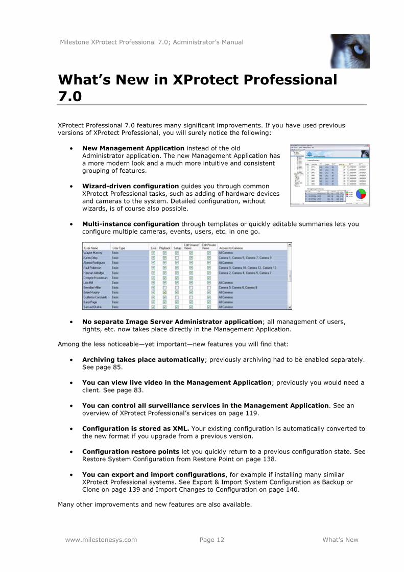
New Management Application instead of the old
Administrator application. The new Management Application has a more modern look and a much more intuitive and consistent grouping of features.
Wizard-driven configuration guides you through common
XProtect Professional tasks, such as adding of hardware devices and cameras to the system. Detailed configuration, without wizards, is of course also possible.
Multi-instance configuration through templates or quickly editable summaries lets you
configure multiple cameras, events, users, etc. in one go.
No separate Image Server Administrator application; all management of users,
rights, etc. now takes place directly in the Management Application. Among the less noticeable—yet important—new features you will find that:
Archiving takes place automatically; previously archiving had to be enabled separately.
See page 85.
You can view live video in the Management Application; previously you would need a
client. See page 83.
You can control all surveillance services in the Management Application. See an
overview of XProtect Professional’s services on page 119.
Configuration is stored as XML. Your existing configuration is automatically converted to
the new format if you upgrade from a previous version.
Configuration restore points let you quickly return to a previous configuration state. See Restore System Configuration from Restore Point on page 138.
You can export and import configurations, for example if installing many similar XProtect Professional systems. See Export & Import System Configuration as Backup or Clone on page 139 and Import Changes to Configuration on page 140.
Many other improvements and new features are also available.
Milestone XProtect Professional 7.0; Administrator’s Manual
www.milestonesys.com Page 13 System & Requirements
System & Requirements
Minimum System Requirements
The following are minimum system requirements for running XProtect Professional and associated applications. Visit the Milestone website, www.milestonesys.com, for the most recent system performance parameters.
Tip: DirectX is a software requirement for several of the components listed in the following. To check which DirectX version is installed on a computer, click Start, select Run..., and type dxdiag. When you click OK, the DirectX Diagnostic Tool window will open; version information is displayed
near the bottom of its System tab. Should the server require a DirectX update, the latest versions of DirectX are available from http://www.microsoft.com/downloads/.
Surveillance System Server
Operating System Microsoft® Windows® XP Professional (32 bit or 64 bit*), Windows Server 2003 (32 bit or 64 bit*), Windows Server 2008 R1/R2 (32 bit or 64 bit*),
Windows Vista™ Business (32 bit or 64 bit*), Windows Vista Enterprise (32
bit or 64 bit*), Windows Vista Ultimate (32 bit or 64 bit*), Windows 7 Professional (32 bit or 64 bit*), Windows 7 Enterprise (32 bit or 64 bit*) or Windows 7 Ultimate (32 bit or 64 bit*).
CPU Intel® Pentium® 4, 2.4 GHz or higher (CoreTM 2 recommended).
RAM Minimum 1 GB (2 GB or more recommended).
Network Ethernet (1 Gbit recommended).
Graphics Adapter AGP or PCI-Express, minimum 1024 x 768, 16 bit colors.
Hard Disk Type E-IDE, PATA, SATA, SCSI, SAS (7200 RPM or faster).
Hard Disk Space Minimum 1 GB free hard disk space available, excluding space needed for recordings.
Software Microsoft .NET 3.5 Framework Service Pack 1 or newer. DirectX 9.0 or newer required if wishing to run the Viewer application. Windows Help (WinHlp32.exe). All are downloadable from http://www.microsoft.com/downloads/.
* Running as a 32 bit service/application.
Smart Client
Operating System Microsoft Windows XP Professional (32 bit or 64 bit*), Windows Server 2003 (32 bit or 64 bit*), Windows Server 2008 R1/R2 (32 bit or 64 bit*), Windows Vista Business (32 bit or 64 bit*), Windows Vista Enterprise (32 bit or 64 bit*), Windows Vista Ultimate (32 bit or 64 bit*), Windows 7
Professional (32 bit or 64 bit*), Windows 7 Enterprise (32 bit or 64 bit*) or Windows 7 Ultimate (32 bit or 64 bit*).
CPU Intel Core2™ Duo, minimum 2.4 GHz or higher (more powerful CPU recommended for Smart Clients running high number of cameras and
multiple views and displays).
RAM Minimum 1 GB (higher RAM recommended for Smart Clients running high
Milestone XProtect Professional 7.0; Administrator’s Manual
www.milestonesys.com Page 14 System & Requirements
number of cameras and multiple views and displays).
Network Ethernet (100 Mbit or higher recommended).
Graphics Adapter AGP or PCI-Express, minimum 1024 x 768 (1280 x 1024 recommended), 16 bit colors.
Hard Disk Space Minimum 100 MB free.
Software Microsoft .NET 3.5 Framework Service Pack 1 or newer. DirectX 9.0 or newer.
* Running as a 32 bit service/application.
Remote Client
Operating System Microsoft Windows XP Professional (32 bit or 64 bit*), Windows Server 2003 (32 bit or 64 bit*), Windows Server 2008 R1/R2 (32 bit or 64 bit*), Windows Vista Business (32 bit or 64 bit*), Windows Vista Enterprise (32
bit or 64 bit*) and Windows Vista Ultimate (32 bit or 64 bit*), Windows 7 Professional (32 bit or 64 bit*), Windows 7 Enterprise (32 bit or 64 bit*) or Windows 7 Ultimate (32 bit or 64 bit*).
CPU Intel Pentium 4, 2.4 GHz or higher.
RAM Minimum 1 GB (2 GB or higher recommended on Microsoft Windows Vista).
Network Ethernet (100 Mbit or higher recommended).
Graphics Adapter AGP or PCI-Express, minimum 1024 x 768 (1280 x 1024 recommended),
16 bit colors.
Hard Disk Space Minimum 10 MB free.
Software DirectX 9.0 or newer.
* Running as a 32 bit service/application.
PDA Server
The PDA Server is typically installed on the surveillance system server; see the system
requirements for the surveillance system server. Note, however, that to run the PDA Server the following is required on the surveillance system server:
● Microsoft Windows XP Professional (32 bit or 64 bit*) or Windows Server 2003 (32 bit or 64 bit*) * Running as a 32 bit service/application.
● Internet Information Services (IIS) 5.1 or later
● Microsoft .NET Framework 2.0. Note that later versions of. Net Framework may also be present on the server. If .NET Framework 2.0 as well as one or more later versions are present on the server, Windows' default settings may cause a later .NET Framework version to be used instead of .NET Framework 2.0. To verify/change
which .NET Framework version is used, do the following:
1. Click Start and select Control Panel.
2. Click Administrative Tools.
Milestone XProtect Professional 7.0; Administrator’s Manual
www.milestonesys.com Page 15 System & Requirements
3. Click Internet Information Services.
4. In the Internet Information Services window’s left pane, locate and right-click the Default
Web Site item.
5. In the resulting menu, select Properties. This will open the Default Web Site Properties dialog.
6. Select the dialog’s ASP.NET tab. The .NET Framework in use will be indicated in the
ASP.NET version field.
7. If required, change the ASP.NET version to 2.0.50727.
8. Click OK.
9. Close the Internet Information Services and Administrative Tools windows if still open.
PDA Client
Operating System Microsoft Windows Pocket PC 2003/2003 SE/Mobile 5.0.
CPU Intel StrongARM® or 100% compatible.
RAM Minimum 32 MB.
Network Ethernet (256 Kbit or higher recommended)
Graphics Adapter Minimum 320 x 200, 16 bit colors.
Software Microsoft Windows Pocket PC 2003/2003 SE/Mobile 5.0.
Matrix Monitor
Matrix Monitor is a dedicated application for viewing Matrix-triggered video from the XProtect Professional surveillance system. Apart from a few features that are unique to the Matrix Monitor, the Smart Client offers near-identical possibilities for viewing Matrix-triggered video.
Operating System Microsoft Windows XP Professional (32 bit or 64 bit*) and Windows Server 2003 (32 bit or 64 bit*), Windows Vista Business (32 bit or 64 bit*), Windows Vista Enterprise (32 bit or 64 bit*) and Windows Vista Ultimate (32 bit or 64 bit*).
CPU Intel Pentium 4, 2.4 GHz or higher.
RAM Minimum 512 MB (1 GB recommended on Microsoft Windows Vista).
Network Ethernet (100 Mbit or higher recommended).
Graphics Adapter AAGP or PCI-Express, minimum 1024 x 768, 16 bit colors.
Hard Disk Space Minimum 50 MB free.
Software DirectX 9.0 or newer
* Running as a 32 bit service/application.
Milestone XProtect Professional 7.0; Administrator’s Manual
www.milestonesys.com Page 16 System & Requirements
Administrator Rights
When you install XProtect Professional it is important that you have administrator rights on the
computer that should run XProtect Professional. If you only have standard user rights, you will not be able to configure the surveillance system. Consult your IT system administrator if in doubt about your rights.
Important Port Numbers
XProtect Professional uses particular ports when communicating with other computers, cameras,
etc. What is a port? A port is a logical endpoint for data traffic. Networks use different ports for different types of data traffic. Therefore it is sometimes, but not always, necessary to specify which port to use for particular data communication. Most ports are used automatically based on the types of data included in the communication. On TCP/IP networks, port numbers range from 0 to 65536, but only ports 0 to 1024 are reserved for particular purposes. For example, port 80 is used
for HTTP traffic when viewing web pages. When using XProtect Professional, make sure that the following ports are open for data traffic on your network:
Port 20 and 21 (inbound and outbound): Used for FTP traffic. FTP (File Transfer
Protocol) is a standard for exchanging files across networks. FTP uses the TCP/IP standards for data transfer, and is often used for uploading or downloading files to and from servers.
Port 25 (inbound and outbound): Used for SMTP traffic. SMTP (Simple Mail Transfer
Protocol) is a standard for sending e-mail messages between servers. This port should be open since, depending on configuration, some cameras may send images to the surveillance system server via e-mail.
Port 80 (inbound and outbound): Used for HTTP traffic between the surveillance server
and cameras, Remote Client and/or Smart Client, and the default communication port for the surveillance system’s Image Server service. HTTP (HyperText Transfer Protocol) is a standard for exchanging files across networks; widely used for formatting and transmission
of data on the world wide web.
Port 554 (inbound and outbound): Used for RSTP traffic in connection with H.264 video streaming.
Port 1024 and above (outbound only): Used for HTTP traffic between cameras and the surveillance server.
Port 1234 (inbound and outbound): Used for event handling.
Port 1237 (inbound and outbound): Used for communication with the XProtect Central
add-on product (if used by your organization)
Any other port numbers you may have selected to use, for example if you have changed
the server access port (see page 120) from its default port number (80) to another port
number. Consult the administrator of your organization’s firewall if in doubt about how to open ports for traffic.
Milestone XProtect Professional 7.0; Administrator’s Manual
www.milestonesys.com Page 17 System & Requirements
Virus Scanning
Virus scanning on the XProtect Professional server, and computers to which data is archived,
should if possible be avoided:
If you are using virus scanning software on the XProtect Professional server, or on a computer to which data is archived (see page 85), it is likely that the virus scanning will
use a considerable amount of system resources on scanning all the data which is being archived. This may affect system performance negatively. Also, virus scanning software may temporarily lock each file it scans, which may further impact system performance
negatively.
Likewise, virus scanning software on the XProtect Professional server is likely to use a
considerable amount of system resources on scanning data used by the Download Manager (see page 162).
If allowed in your organization, you should therefore disable any virus scanning of affected areas (such as camera databases, etc.) on the XProtect Professional server as well as on any archiving
destinations.
Time Server
All video is time-stamped by XProtect Professional upon reception, but since cameras are separate units which may have separate timing devices, power supplies, etc., camera time and XProtect Professional system time may not correspond fully, and this may occasionally lead to confusion.
If supported by your cameras, we thus recommend you auto-synchronize camera and system time through a time server for consistent synchronization. For information about configuring a time server searching www.microsoft.com for time server, time service, or similar.
Milestone XProtect Professional 7.0; Administrator’s Manual
www.milestonesys.com Page 18 Installation
Installation
This chapter covers installation/upgrade of the XProtect Professional server. For information about installing clients, etc., see the separate manuals for each application.
Do not install XProtect Professional on a mounted drive (that is a drive attached to an empty folder on an NTFS (NT File System) volume, with a label or name instead of a drive letter). If using mounted drives, critical system features may not work as intended; you will, for example, not
receive any warnings if the system runs out of disk space. Prerequisites: Shut down any existing surveillance software. If upgrading, read Upgrade from a
Previous Version (below) first.
1. Insert the XProtect Professional software DVD, wait for a short while, click the XProtect Professional installation link, and then select required language. Alternatively, if you are installing a version downloaded from the internet, run the downloaded installation file from the location you have saved it to.
Depending on your security settings, you may receive one or more security warnings (such as Do you want to run or save this file?, Do you want to run this software? or similar). When this is the case, click the Run button.
2. When the installation wizard starts, click Next to continue.
3. Read and accept the End User License Agreement, then click Next.
4. If an earlier XProtect Professional version (6.0a or later) is present on the server, you will be asked to accept that it is automatically removed during installation of the new version. The automatic removal will not delete any existing recordings or configuration. If asked, we recommend answering Yes, since this will ensure that old versions will not interfere with your new version.
Versions earlier than 6.0 must be removed manually before installing the new version.
5. Select Typical installation and follow the instructions (advanced users may select Custom
installation, and choose which features to install and where to install them).
6. Select Install licensed version. Specify your user name, organization, and Software License
Code (SLC; printed on your Product License Sheet). When ready, click Next.
7. Click the Install button to begin the software installation. During the process, all the necessary components will be installed one after the other.
8. Click Finish on the last step to complete the installation.
If a Status Information window appears on your screen during installation, simply click its OK button. The window simply provides a summary of your installation. When installation is complete, you can begin configuring your XProtect Professional through its Management Application: Double-click the Management Application desktop shortcut or select Start > All Programs > Milestone XProtect Professional > Management Application. See more in Get Your
System Up & Running on page 21.
Milestone XProtect Professional 7.0; Administrator’s Manual
www.milestonesys.com Page 19 Installation
Upgrade from a Previous Version
Upgrading XProtect Professional is an easy task, and you need not worry about spending hours
reconfiguring your software. The following information applies if upgrading from one XProtect Professional version to another as well as if upgrading to XProtect Professional from a lower product in the XProtect product portfolio.
Prerequisites
Take note of your SLC (Software License Code). The SLC will change when the software version number changes. If your SLC has changed, so have your DLKs (Device License Keys). You get DLKs (Device License Keys) as part of the software registration process on the Milestone website,
www.milestonesys.com. Upon registration, all your DLKs are sent to you as a single .dlk file attached to an e-mail. Often, your XProtect Professional vendor will take care of the process for you. When you have installed the new version of XProtect Professional, you should import the new DLK file as described later.
Back Up Your Current Configuration
When you install the new version of XProtect Professional, it will inherit the configuration from your
old version. However, we recommend that you make regular backups of your server configuration as a disaster recovery measure. Upgrading your server is no exception. While it is rare to lose your
configuration (cameras, schedules, views, etc), it can happen under unfortunate circumstances. Luckily, it takes only a minute to back up your existing configuration: The following describes backup of XProtect Professional versions prior to 7.0, which is the most likely need when upgrading to version 7.0. If you need information about how to back up your
XProtect Professional 7.0 configuration, see page 144.
1. Create a folder called Backup on a network drive, or on removable media.
2. On the XProtect Professional server, open My Computer, and navigate to C:\Program Files\Milestone\Milestone Surveillance.
3. Copy the following files and folders into your Backup folder:
All configuration (.ini) files
All scheduling (.sch) files
The file users.txt (only present in a few installations)
The folder SmartClientViewGroups and all of its content
The folder RemoteClientViewGroups and all of its content
Note that some of the files/folders may not exist if upgrading from old software versions.
Remove the Current Version
In most cases, you do not need to manually remove the old version of XProtect Professional before you install the new version. The old version is removed when you install the new version. Note, however, that versions earlier than 6.0 must be removed manually before installing the new version.
Milestone XProtect Professional 7.0; Administrator’s Manual
www.milestonesys.com Page 20 Installation
Install the New Version
Run the installation file for the new software version. Select the installation options that best fit your needs.
Import the New DLKs
1. Open the Management Application.
2. In the Management Application's File menu, select Import DLKs...
3. Browse to the location at which you have saved the received .dlk file, select the file, and click Open. All the new DLKs are now imported into XProtect Professional.
Restore a Configuration Backup (if Required)
If for some reason after installing the new software version you have lost your configuration, you can restore your configuration, provided you have followed the previous instructions. Since configuration is stored in a new format in XProtect Professional 7.0, your backed-up configuration must be converted to the new format before you can use it. Contact your Milestone vendor for information about how to convert and restore your configuration backup.
Upgrade Video Device Drivers
Video device drivers are small programs used for controlling/communicating with the hardware devices connected to an XProtect Professional system. Video device drivers are installed automatically during the installation of your XProtect Professional system. However, new versions of the video device drivers—so-called Device Packs—are released and made available for free on www.milestonesys.com from time to time.
We therefore recommend that you regularly visit the Milestone website (look under Support > Downloads) and download the latest Device Pack. When updating video device drivers, there is no need to remove the old video device drivers first; simply install the latest version on top of any old version you may have. For detailed information, see page 150.
Upgrade Smart Clients
Smart Client users should now remove their old Smart Client versions and install the new one:
1. On the required computers, open Windows' Add or Remove Programs dialog (Start > Control Panel > Add or Remove Programs).
2. In the Add or Remove Programs dialog, select the Milestone XProtect Smart Client entry, and click the Remove button. A wizard window will open. Follow the wizard’s steps, and click Finish when ready.
3. Now open a browser and connect to XProtect Professional at the following address:
http://[IP address or hostname of server]:[port number; default is 80]
Example: http://123.123.123.123:80
4. From the welcome page that appears, download and install the latest Smart Client version.
5. If required, download and install any Smart Client plugins needed.
Milestone XProtect Professional 7.0; Administrator’s Manual
www.milestonesys.com Page 21 Get Your System Up and Running
Get Your System Up and Running
The following outlines the tasks typically involved in setting up a working XProtect Professional system. Note that although information is presented as a checklist, a completed checklist does not
in itself guarantee that the system will match the exact needs of your organization. To make the system match the needs of your organization, it is highly recommended that you monitor and adjust the system once it is running.
For example, it is often a very good idea to spend time on testing and adjusting the motion detection sensitivity settings for individual cameras under different physical conditions (day/night, windy/calm, etc.) once the system is running.
Tip: Check the boxes in this checklist as you go along.
Verify Initial Configuration of Cameras and other Hardware Devices
Before doing anything on XProtect Professional, make sure the hardware devices (cameras, video encoders, etc.) you are going to use are correctly installed and configured with IP addresses, passwords, etc. as specified by the manufacturers. Such initial configuration is required in order to be able to connect the devices to the network and XProtect Professional.
Register Your XProtect Professional Software and Get DLKs (This step may not be
required; your XProtect Professional vendor often takes care of the process for you. If you have received a Device License Key file from your vendor, you can skip this step.) You must register your software and get a Device License Key (DLK) for every device
(cameras, etc.) you are going to use on your XProtect Professional system. Upon registration, all your DLKs are sent to you as a single .dlk file attached to an e-mail.
● Go to www.milestonesys.com and click the Software Registration link.
● Log in to the online registration system. If you do not yet have a login, click the New To The System? link, and follow the instructions. When ready, log in using the registered e-
mail address and password. The DLKs will be e-mailed to the e-mail address specified in your login, so it is a good idea to use a single e-mail account for everyone who should be able to retrieve the DLKs.
● If you have not yet registered your SLC (Software License Code; listed on your product
license sheet), do so by clicking the Add SLC link and completing the SLC registration steps before proceeding.
● When ready, click the link representing your SLC.
● For each device required on your system, click the Add new MAC link and specify the
device’s MAC address and a description. The MAC address is a 12 digit hexadecimal (example: 0123456789AF), occasionally called a serial number by some vendors. For
information about how to find the MAC address for a specific device, refer to the manual for the device in question.
● For video encoder devices, specify the number of cameras to be used with the device.
Remember that you are allowed to install and use only the number of cameras covered by your license agreement; regardless of your number of available DLKs. For example, a fully used four-port video encoder counts as four cameras; it will thus use four licenses
even though its four cameras are connected through a single device.
● Click Submit. The device is added to a list of devices under your SLC.
Milestone XProtect Professional 7.0; Administrator’s Manual
www.milestonesys.com Page 22 Get Your System Up and Running
● If more devices are required, click the Add New MAC link and repeat the process.
● When ready, click the Get DLKs by e-mail link to have DLKs for all the devices
registered under your SLC e-mailed to you.
Install XProtect Professional
See page 18. If upgrading an existing version of XProtect Professional, see Upgrade from a Previous Version on page 19.
Open the Management Application
See Access the Management Application on page 23.
Import Your DLKs Now it is time to import the Device License Keys into XProtect Professional; see page 52.
Add Hardware Devices in XProtect Professional XProtect Professional can quickly scan your network for relevant hardware devices (cameras, video encoders, etc.), and add them to your system. See page 26.
Configure Cameras in XProtect Professional You can specify a wide variety of settings for each camera connected to your XProtect Professional system. Settings include video format, resolution, motion detection sensitivity,
where to store and archive recordings, any PTZ (Pan/Tilt/Zoom) preset positions, association with microphones and speakers, etc. See page 57. What does ―... archive recordings‖ mean? Archiving—an integrated and automated feature—helps you store recordings beyond the capabilities of XProtect Professional’s standard database. Archiving thus maximizes storage capacity and minimizes risk. See page 85 for more
information.
Configure Events, Input & Output If required, system events, for example based on input from sensors, etc., can be used for
automatically triggering actions in XProtect Professional. Examples of actions: starting or stopping recording on cameras, switching to a particular video frame rate, making PTZ cameras move to specific preset positions. Events can also be used for activating hardware output, such
as lights or sirens. See page 107.
Configure Scheduling
When do you want to archive? Do you want some cameras to transfer video to XProtect Professional at all times, and other cameras to transfer video only within specific periods of time, or when specific events occur? With the scheduling feature, you can specify this as well as when you want to receive notifications from the system. For PTZ cameras with patrolling
(automatic movement between preset positions), you are furthermore able to specify use of specific patrolling profiles for specific periods of time. See Configure General Scheduling & Archiving on page 95 and Configure Camera-specific Scheduling on page 97.
Configure Clients' Access to XProtect Professional
A number of different client applications (see page 151) is included with XProtect Professional.
You can specify whether you want clients to access the XProtect Professional server from the internet, how many clients you want to be able to connect simultaneously, etc. See page 120.
Configure Users
Now specify who should be able to access your XProtect Professional system, and how. Do you want password protection for the Management Application? Who should have client access, and with which rights? See Configure User Access Wizard on page 46, Add Basic Users on page
Milestone XProtect Professional 7.0; Administrator’s Manual
www.milestonesys.com Page 23 Get Your System Up and Running
122, Add Windows Users on page 123, Add User Groups on page 124, and Configure User & Group Rights on page 124.
Configure the Download Manager The Download Manager lets you manage which features users will see on a targeted welcome page when they connect to the XProtect Professional server. Such features can include access
to client applications, additional client language versions, plugins, etc. See page 162.
Tip: The Download Manager comes with a default configuration ensuring that users get access to the Smart Client and Remote Client in the same language as your XProtect Professional
server without you having to do anything. The above list represents the configuration steps that most administrators are likely to cover.
Additional configuration is of course possible, for example if your organization wants to use the PDA Client solution (see page 151), Matrix video sharing features (see page 133) or similar. Note that the behavior of the Management Application can be customized (see page 25). Descriptions here are, however, always based on the Management Application’s default behavior.
Access the Management Application
You access the Management Application by double-clicking the Management Application desktop shortcut. Alternatively, use Windows' Start menu: Start > All Programs > Milestone XProtect Professional > Management Application. Depending on your configuration, access to the Management Application may be password-
protected (see page 24). Read more about the Management Application in the following.
Milestone XProtect Professional 7.0; Administrator’s Manual
www.milestonesys.com Page 24 Management Application
Management Application
The Management Application is XProtect Professional’s server-side user interface; all management of your surveillance system is handled here. You access the Management application by double-
clicking the Management Application desktop shortcut. Alternatively, use Windows’ Start menu: Start > All Programs > Milestone XProtect Professional > Management Application.
Password Protection
By default, anyone who is able to log in to the XProtect Professional server is able to use the Management Application. The reason for this is that such people are likely to have administrator rights. If required, you can password protect access to the Management Application for additional
security:
1. In the Management Application’s navigation pane, expand Advanced Configuration, expand Users, right-click Administrator, and select Properties.
2. Under Management protection, select Enable.
3. Specify required password, and repeat it to be sure you have specified it correctly. Only
use the Old password field if changing an existing password or disabling management protection, in which case the old password is required to prove that you have the rights to make the changes.
5. Click OK.
6. Save your configuration changes by clicking the Save Configuration button in the
Management Application’s toolbar.
Apply/Save Configuration Changes
Whenever you make changes in your XProtect Professional configuration, you will be asked to apply them:
If you made the changes in one of the Management Application’s dialogs, you simply apply them by clicking OK.
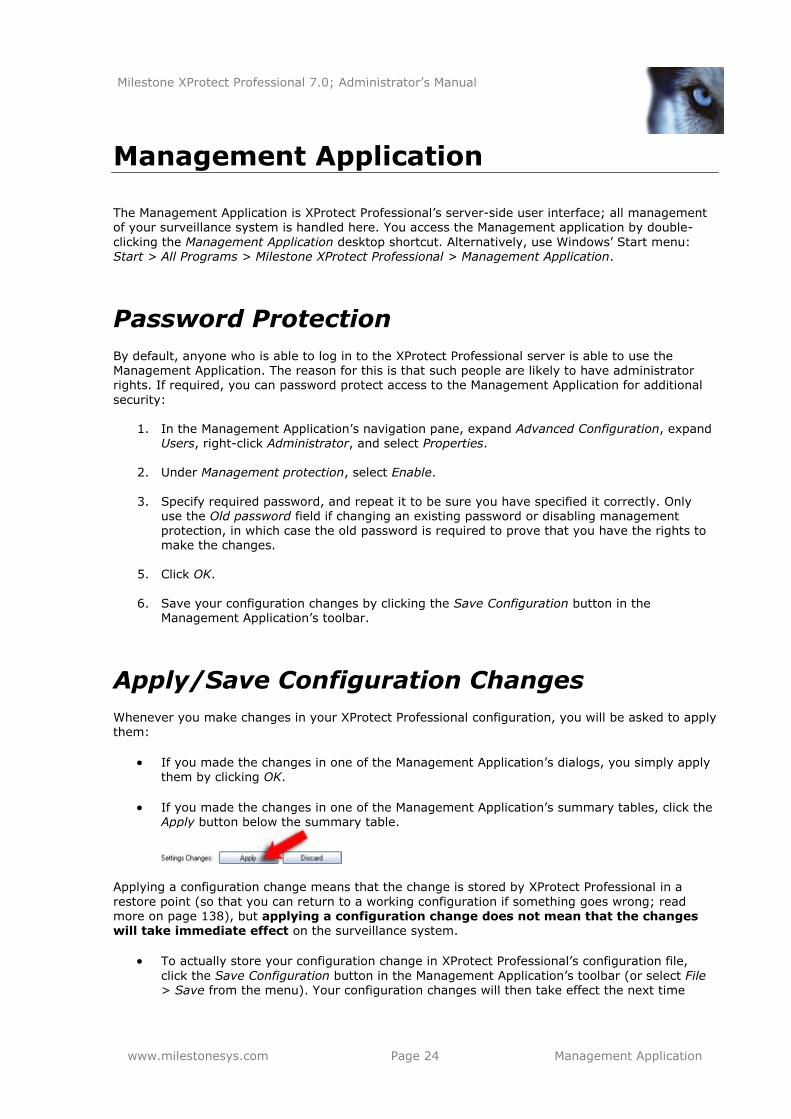
If you made the changes in one of the Management Application’s summary tables, click the Apply button below the summary table.
Applying a configuration change means that the change is stored by XProtect Professional in a
restore point (so that you can return to a working configuration if something goes wrong; read
more on page 138), but applying a configuration change does not mean that the changes will take immediate effect on the surveillance system.
To actually store your configuration change in XProtect Professional’s configuration file,
click the Save Configuration button in the Management Application’s toolbar (or select File > Save from the menu). Your configuration changes will then take effect the next time
Milestone XProtect Professional 7.0; Administrator’s Manual
www.milestonesys.com Page 25 Management Application
XProtect Professional’s services (see page 119) are restarted.
If you want your configuration changes to have immediate effect, XProtect Professional’s
services must be restarted: Click the Save Changes and Restart Surveillance Services button in the Management Application’s toolbar (or select File > Save Changes and Restart Services from the menu).
IMPORTANT: While services are restarted, it will not be possible to view or record video. Restarting the services typically only takes some seconds, but in order to minimize disruption you may want to restart services at a time when you do not expect important incidents. Users connected to XProtect Professional through clients will typically remain logged in during the
services restart, but they will experience a short video outage.
Change/Reset Behavior
You can change the way the Management Application behaves. For example, the Management Application will by default ask you to confirm many of your actions. If you find this annoying, you can change the Management Application’s behavior, so it will not ask you again.
1. In the Management Application’s menu bar, select Application Settings > Application Behavior...
2. For each action, you can now select how the Management Application should behave. Examples:
When you attempt to delete a hardware device, should the Management
Application ask you to confirm that you want to delete the hardware device, or should it delete the hardware device straight away without asking?
You can use a maximum of 64 cameras at a time on a single XProtect Professional
server. If you add more than 64 cameras, should the Management Application warn you or not?
Note that selectable behavior may vary, depending on the type of action
3. Click OK.
4. Save your configuration changes by clicking the Save Configuration button in the
Management Application’s toolbar. Tip: You can quickly restore default settings by clicking the button below the behavior list.
Milestone XProtect Professional 7.0; Administrator’s Manual
www.milestonesys.com Page 26 Wizards
Wizards
This chapter describes the wizards that guide you through common tasks in XProtect Professional. Wizards are a great advantage, but they typically only cover the most important of XProtect
Professional’s many configuration options. For detailed descriptions of all of XProtect Professional’s configuration options, see the subsequent chapters in this manual.
The Add Hardware Devices wizard (see the following) helps you add cameras and other
hardware devices, such as video encoders, etc., to your XProtect Professional system. If
microphones and/or speakers are attached to a hardware device, they are automatically added as well.
The Configure Video and Recording wizard (see page 38) helps you quickly configure your
cameras' video and recording properties.
The Adjust Motion Detection wizard (see page 45) helps you quickly configure your cameras' motion detection properties.
The Configure User Access wizard (see page 46) helps you quickly configure clients' access to the XProtect Professional server as well as which users should be able to use clients.
Finally, the Replace Hardware wizard (see page 48) helps you replace a hardware device—
which you have previously added to and configured on your surveillance system—with a new one. This is relevant if you want to replace a physical camera on your network.
Add Hardware Devices Wizard
You add cameras and other hardware devices, such as video encoders, to your XProtect Professional system through the Add Hardware Devices... wizard. If microphones and/or speakers are attached to a hardware device, they are automatically added as well. You are allowed to use up to 64 cameras. Note that, if required, it is possible to add more cameras than you are allowed to use. If using video encoder devices on your system, bear in mind that
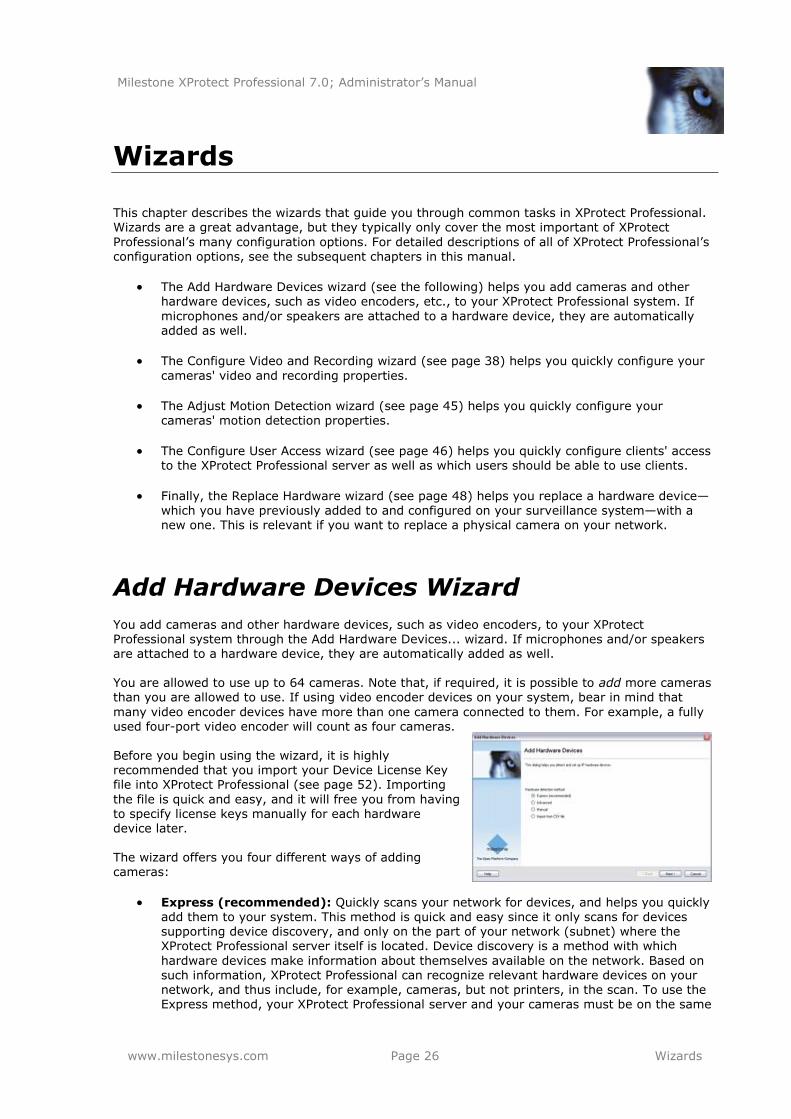
many video encoder devices have more than one camera connected to them. For example, a fully used four-port video encoder will count as four cameras. Before you begin using the wizard, it is highly recommended that you import your Device License Key file into XProtect Professional (see page 52). Importing
the file is quick and easy, and it will free you from having to specify license keys manually for each hardware device later. The wizard offers you four different ways of adding cameras:
Express (recommended): Quickly scans your network for devices, and helps you quickly
add them to your system. This method is quick and easy since it only scans for devices supporting device discovery, and only on the part of your network (subnet) where the XProtect Professional server itself is located. Device discovery is a method with which
hardware devices make information about themselves available on the network. Based on such information, XProtect Professional can recognize relevant hardware devices on your network, and thus include, for example, cameras, but not printers, in the scan. To use the Express method, your XProtect Professional server and your cameras must be on the same
Milestone XProtect Professional 7.0; Administrator’s Manual
www.milestonesys.com Page 27 Wizards
layer 2 network, that is a network where all servers, cameras, etc. can communicate without the need for a router. See page 27.
Advanced: Scans your network for hardware devices based on your specifications regarding required IP ranges, discovery methods, drivers, and device user names and passwords. See page 29.
Manual: Lets you specify details about each hardware device separately. A good choice if you only want to add a few hardware devices, and you know their IP addresses, required user names and passwords, etc. See page 32.
Import from CSV file: Lets you import data about cameras as comma-separated values from a file; an effective method if setting up several similar systems. See page 35.
Express Method
The Express option scans your network for relevant hardware devices, and helps you quickly add
them to your system. With the Express option, the wizard only scans for hardware devices supporting device discovery, and only on the part of your network (subnet) where the XProtect Professional server itself is located. What is device discovery? Device discovery is a method with which hardware devices make information about themselves available on the network. Based on such information, XProtect Professional can quickly recognize relevant hardware devices, such as cameras and video encoders,
and include them in the scan. To use the Express method, your XProtect Professional server and your cameras must be on the same layer 2 network; that is a network where all servers, cameras, etc. can communicate without the need for a router. The reason for this is that device discovery relies on direct communication between the XProtect Professional server and the cameras. If you know that routers are used on your network, use the Advanced method (see page 29) or Manual method (see
page 32) instead. If you are asked for Device Licence Keys (DLKs) when starting the wizard, see page 52. When using the Express option, the wizard is divided into a number of pages:
Hardware Detection and Verification
The wizard automatically scans your network for hardware devices, and lists devices real-time as they are detected. All properties on a white background are editable; properties on a light blue background cannot be edited. Wait until the scan is complete. If the scan takes very long, you can stop it with the Stop Scan button; the wizard will remember any devices detected up to that point. When the scan is complete:
Go through the list of detected hardware devices to see if it contains unwanted devices. If it does, clear the check box in the Use column for each unwanted device.
If any hardware devices are missing from the list, verify that the missing hardware devices
support device discovery, verify that they are working and connected to the same part of the network as the XProtect Professional server, then click the Rescan button. If hardware devices detected in the first scan cannot be detected in the second scan, the wizard will still
remember them.
In the User name column, select or type the user name required to access the administrator account on each hardware device. The administrator account gives full
access, and XProtect Professional is going to need that for each hardware device. Many
Milestone XProtect Professional 7.0; Administrator’s Manual
www.milestonesys.com Page 28 Wizards
organizations use the hardware device manufacturer’s default user names for their hardware devices. If that is the case in your organization, select <default> (do not type a manufacturer’s default user name as this can be a source of error; trust that XProtect
Professional will know the manufacturer’s default user name). Other typical user names, such as admin or root are also selectable from the list. If requiring a user name which is not on the list, simply type the required user name.
Tip: User names you type yourself will subsequently be added to the list, so you can easily select them later.
In the Password column, specify the password required to access the administrator
account on each hardware device. The administrator account gives full access, and XProtect Professional is going to need that for each hardware device. If the same password is used for all the hardware devices, use the Password field below the list, then click the Set on All
button (which becomes available when you specify a password in the field).
Tip: If in doubt about which password to use, ask yourself: Have you previously used a web page to connect to the hardware device and view video? While you did this, were you also able to configure camera settings, such as resolution, etc.? If you can answer yes to both questions, you were in all likelihood using the hardware device’s administrator
account, in which case you will also know the password. Tip: If you are still in doubt, look in the Device Pack Release Notes, available from the Downloads section of www.milestonesys.com. This will show you the administrator account user name for each supported hardware device. For obvious reasons it will not show you
the password.
When you have specified a password for all hardware devices on the list (except unwanted devices), click Next. This will verify that all passwords are correct, and mark each device in the Verified column. If any hardware devices cannot be verified, make sure you have specified the correct passwords, then click Next again.
If you have valid Device Licence Keys (DLKs) for all the detected hardware devices, the next wizard page will provide you with an overview, and ask you to select names for cameras, etc. If a valid DLK is missing for one or more of the detected hardware devices,
the next wizard page will prompt you to supply valid DLKs before you continue.
Missing DLKs (if Applicable)
If a valid Device License Key (DLK) is missing for one or more of the detected hardware devices, the wizard will prompt you to supply valid DLKs. If so, specify a valid DLK for each listed hardware device, either manually in the Device License key (DLK) column or by clicking the Import DLKs button to import the DLKs from your .dlk file.
Then click Next. What is a .dlk file? You get DLKs as part of the software registration process on the Milestone website, www.milestonesys.com. Upon registration, all your DLKs are sent to you as a single .dlk file attached to an e-mail. Often, your XProtect Professional vendor will take care of the process for you; in which case all you have to do is import the .dlk file, then XProtect Professional will know
the DLKs for all your hardware devices.
Overview and Names
On the last page, the wizard provides you with a detailed overview, listing each camera, microphone and/or speaker attached to the hardware devices. All properties on a white background are editable; properties on a light blue background cannot be edited.
All cameras, etc. are by default enabled (selected in the Enable column). This means that
they are able to communicate with XProtect Professional. If required, you can disable
Milestone XProtect Professional 7.0; Administrator’s Manual
www.milestonesys.com Page 29 Wizards
individual cameras, microphones or speakers, and thus prevent them from communicating with XProtect Professional.
All cameras, etc. get automatically generated names based on their type plus a number (examples: Camera 1, Microphone 26). Such names are shown in the Name column. If required, you change names manually, or select another name format in the Auto-generated name format list:
o Device type + number: The default name format.
Example: Camera 1
o Custom text - Device type + number: Names will consist of a text of your choice (specified in the Custom text field) followed by a dash, type information and a number.
Example: Airport Security - Camera 1
o Address - Device type + number: Names will consist of the hardware device address followed by a dash, type information and a number. Example: 10.10.123.73 - Camera 1
o Custom text - Address - Device type + number: Names will consist of a text of your choice (specified in the Custom text field) followed by a dash, then the hardware device address followed by a dash, type information and a number. Example: Airport Security - 10.10.123.73 - Camera 1
o Hardware model - Device type + number: Names will consist of hardware device model information followed by a dash, type information and a number.
Example: Axis P1311 - Camera 1
o Hardware model - Custom text - Device type + number: Names will consist of hardware device model information followed by a dash, then a text of your choice (specified in the Custom text field), a dash, type information and a number. Example: Axis P1311 - Airport Security - Camera 1
o Hardware model - Address - Device type + number: Names will consist of hardware device model information followed by a dash, then the hardware device address, a dash, type information and a number. Example: Axis P1311 - 10.10.123.73 - Camera 1
Tip: Need other name formats? Remember you can change names manually by overwriting
all or parts of them in the Name column. If you change camera names manually, remember that camera names must be unique, and must not contain any of the following special characters: < > & ' " \ / : * ? | [ ]
When ready, click Finish.
Advanced Method
The Advanced option scans your network for relevant hardware devices based on your
specifications regarding required IP ranges, discovery methods, drivers, and device user names and passwords. If you are asked for Device Licence Keys (DLKs) when starting the wizard, see page 52.
When using the Advanced option, the wizard is divided into a number of pages. All properties on a white background are editable; properties on a light blue background cannot be edited.
Milestone XProtect Professional 7.0; Administrator’s Manual
www.milestonesys.com Page 30 Wizards
Device Discovery, IP Ranges, Drivers and Authentication
First specify which IP address ranges you want to scan. By default, the wizard suggests scanning the subnet on which the XProtect Professional server is located. To add additional ranges, or edit existing ones, click the Add or Edit button as required, then specify:
Start address: First IP address in required range.
End address: Last IP address in required range. The start and end IP address may be
identical, allowing you to only scan for a single hardware device.
Use TCP port scanning: If scanning for hardware devices which support TCP/HTTP—most devices do—keep the check box selected.
Perform scanning on port number(s): Port number(s) on which to scan. If you want to scan on more than one port number, separate them by commas (example: 80,88,90). If you want to scan on a range of port numbers, separate the first and last port number in the range by a colon (example: 80:90 will scan on all ports from 80 up to and including
90). You can also combine individual port numbers and ranges (example: 77,80:90,97,99). Default is port 80. If your hardware devices are located behind a NAT-enabled router or a firewall, you may need to specify a different port number. When this is the case, also remember to configure the router/firewall so it maps the port and IP addresses used by the hardware devices.
Now select which drivers to use when scanning. By default, XProtect Professional will use all known drivers. If your organization only uses certain hardware device makes and/or models, you can achieve faster scanning by selecting only the drives required for those hardware devices. If that is the case, click the Select... button, then specify:
Detect: Select drives you want to use when scanning.
Tip: The list of drivers is typically very long, and by default all drivers are selected. With the Select All and Clear All buttons, you can avoid having to select/clear all check boxes manually.
Now you add user name/password combinations required to access the administrator account on each of your hardware devices. The administrator account gives full access, and XProtect Professional is going to need that for each hardware device.
User name: Select or type the user name required to access the administrator account on
each hardware device. Many organizations use the hardware device manufacturer’s default user names for their hardware devices. If that is the case in your organization, select <default> (do not type a manufacturer’s default user name as this can be a source of error; trust that XProtect Professional will know the manufacturer’s default user name). Other typical user names, such as admin or root are also selectable from the list. If
requiring a user name which is not on the list, simply type the required user name.
Tip: User names you type yourself will subsequently be added to the list, so you can easily select them later.
Password: Specify the password required to access the administrator account.
If different user name/password combinations are used across your hardware devices, make sure you add all required combinations.
Tip: If in doubt about which user name/password to use, ask yourself: Have you previously
used a web page to connect to the hardware device and view video? While you did this, were you also able to configure camera settings, such as resolution, etc.? If you can
Milestone XProtect Professional 7.0; Administrator’s Manual
www.milestonesys.com Page 31 Wizards
answer yes to both questions, you were in all likelihood using the hardware device’s administrator account, in which case you will also know the user name/password.
Tip: If you are still in doubt, look in the Device Pack Release Notes, available from the Downloads section of www.milestonesys.com. This will show you the administrator account user name for each supported hardware device. For obvious reasons it will not show you the password.
Add: Click to add user a name/password combination.
When ready, click Next.
Detected and Verified Hardware Devices
The wizard automatically scans required IP address ranges for hardware devices, and lists detected
devices real-time as they are detected. The scanning takes place in three tempi: first the express method (where the wizard quickly scans for devices supporting device discovery), then two more thorough methods. During the two thorough methods, the wizard continuously shows you which IP address it is scanning (Example: Now scanning 10.10.75.110).
Wait until the scan is complete. If the scan takes very long, you can stop it with the Stop Scan button; the wizard will remember any devices detected up to that point.
When the scan is complete:
Go through the list of detected hardware devices to see if it contains unwanted devices. If
it does, clear the check box in the Use column for each unwanted device.
If any hardware devices are missing from the list, verify that the missing hardware devices
are working and that they are located within the specified IP address ranges, then click the Rescan button. If hardware devices detected in the first scan cannot be detected in the second scan, the wizard will still remember them.
For all detected hardware devices, XProtect Professional has verified that user
names/passwords are correct, and marked each device in the Verified column. If any hardware devices could not be verified, make sure you have specified the correct user names/passwords.
Click Next. If you have valid Device Licence Keys (DLKs) for all the detected hardware
devices, the next wizard page will provide you with an overview, and ask you to select names for cameras, etc. If a valid DLK is missing for one or more of the detected hardware devices, the next wizard page will prompt you to supply valid DLKs before you continue.
Missing DLKs (if Applicable)
If a valid Device License Key (DLK) is missing for one or more of the detected hardware devices, the wizard will prompt you to supply valid DLKs. If so, specify a valid DLK for each listed hardware device, either manually in the Device License key (DLK) column or by clicking the Import DLKs button to import the DLKs from your .dlk file.
Then click Next.
What is a .dlk file? You get DLKs as part of the software registration process on the Milestone website, www.milestonesys.com. Upon registration, all your DLKs are sent to you as a single .dlk file attached to an e-mail. Often, your XProtect Professional vendor will take care of the process for you; in which case all you have to do is import the .dlk file, then XProtect Professional will know the DLKs for all your hardware devices.
Milestone XProtect Professional 7.0; Administrator’s Manual
www.milestonesys.com Page 32 Wizards
Overview and Names
On the last page, the wizard provides you with a detailed overview, listing each camera, microphone and/or speaker attached to the hardware devices.
All cameras, etc. are by default enabled (selected in the Enable column). This means that
they are able to communicate with XProtect Professional. If required, you can disable individual cameras, microphones or speakers, and thus prevent them from communicating with XProtect Professional.
All cameras, etc. get automatically generated names based on their type plus a number
(examples: Camera 1, Microphone 26). Such names are shown in the Name column. If required, you change names manually, or select another name format in the Auto-generated name format list:
o Device type + number: The default name format.
Example: Camera 1
o Custom text - Device type + number: Names will consist of a text of your choice (specified in the Custom text field) followed by a dash, type information and a number. Example: Airport Security - Camera 1
o Address - Device type + number: Names will consist of the hardware device address followed by a dash, type information and a number.
Example: 10.10.123.73 - Camera 1
o Custom text - Address - Device type + number: Names will consist of a text of your choice (specified in the Custom text field) followed by a dash, then the
hardware device address followed by a dash, type information and a number. Example: Airport Security - 10.10.123.73 - Camera 1
o Hardware model - Device type + number: Names will consist of hardware device model information followed by a dash, type information and a number. Example: Axis P1311 - Camera 1
o Hardware model - Custom text - Device type + number: Names will consist of hardware device model information followed by a dash, then a text of your choice (specified in the Custom text field), a dash, type information and a number.
Example: Axis P1311 - Airport Security - Camera 1
o Hardware model - Address - Device type + number: Names will consist of hardware device model information followed by a dash, then the hardware device
address, a dash, type information and a number. Example: Axis P1311 - 10.10.123.73 - Camera 1
Tip: Need other name formats? Remember you can change names manually by overwriting all or parts of them in the Name column. If you change camera names manually, remember that camera names must be unique, and must not contain any of the following
special characters: < > & ' " \ / : * ? | [ ] When ready, click Finish.
Manual Method
The Manual option lets you specify details about each hardware device separately. A good choice if you only want to add a few hardware devices, and you know their IP addresses, required user names and passwords, etc.
Milestone XProtect Professional 7.0; Administrator’s Manual
www.milestonesys.com Page 33 Wizards
If you are asked for Device Licence Keys (DLKs) when starting the wizard, see page 52. When using the Manual option, the wizard is divided into a number of pages:
Hardware Device Information, Driver Selection and Verification
Specify information about each hardware device you want to add. All properties on a white background are editable; properties on a light blue background cannot be edited.
Use: Indicates that you want to include the hardware device in the scan. To begin with,
leave the box cleared. Provided XProtect Professional can find a suitable driver for the
hardware device, the Use box will automatically be selected later.
Address: IP address or DNS host name of the hardware device.
Port: Port number on which to scan. Default is port 80. If a hardware device is located behind a NAT-enabled router or a firewall, you may need to specify a different port
number. When this is the case, also remember to configure the router/firewall so it maps the port and IP address used by the hardware device.
User name: Select or type the user name required to access the administrator account on
each hardware device. Many organizations use the hardware device manufacturer’s default user names for their hardware devices. If that is the case in your organization, select <default> (do not type a manufacturer’s default user name as this can be a source of
error; trust that XProtect Professional will know the manufacturer’s default user name). Other typical user names, such as admin or root are also selectable from the list. If requiring a user name which is not on the list, simply type the required user name.
Tip: User names you type yourself will subsequently be added to the list, so you can easily select them later.
Password: Password required for accessing the administrator account. A few hardware
devices do not require user name/password for access; if such hardware devices are used in your organization, you can leave the field blank.
Tip: If in doubt about which user name/password to use, ask yourself: Have you previously used a web page to connect to the hardware device and view video? While you did this, were you also able to configure camera settings, such as resolution, etc.? If you can
answer yes to both questions, you were in all likelihood using the hardware device’s administrator account, in which case you will also know the user name/password. Tip: If you are still in doubt, look in the Device Pack Release Notes, available from the Downloads section of www.milestonesys.com. This will show you the administrator account user name for each supported hardware device. For obvious reasons it will not show you the password.
Hardware Driver: Ability to select which driver to use with the hardware device. Note that the default option is Auto-detect hardware type: XProtect Professional can itself find the right driver if you click the Auto-detect button.
Verified: Read-only field indicating whether access to the hardware device has been verified. Hardware devices for which you have specified correct address, port, user name
and password will be verified immediately if you use the auto-detect method. If you select
drivers manually, access will be verified once you click Next. Tip: If using the Auto-detect feature, you can enter information about other devices while the auto-detection goes on. Example: You enter information about one device, and use auto-detection to find the right driver for that device. While auto-detection for the first device takes place, you begin entering information about a second device. This can speed up things.
Milestone XProtect Professional 7.0; Administrator’s Manual
www.milestonesys.com Page 34 Wizards
Missing DLKs (if Applicable)
If a valid Device License Key (DLK) is missing for one or more of the detected hardware devices, the wizard will prompt you to supply valid DLKs. If so, specify a valid DLK for each listed hardware device, either manually in the Device License key (DLK) column or by clicking the Import DLKs button to import the DLKs from your .dlk file. Then click Next.
What is a .dlk file? You get DLKs as part of the software registration process on the Milestone website, www.milestonesys.com. Upon registration, all your DLKs are sent to you as a single .dlk
file attached to an e-mail. Often, your XProtect Professional vendor will take care of the process for you; in which case all you have to do is import the .dlk file, then XProtect Professional will know the DLKs for all your hardware devices.
Overview and Names
On the last page, the wizard provides you with a detailed overview, listing each camera, microphone and/or speaker attached to the hardware devices.
All cameras, etc. are by default enabled (selected in the Enable column). This means that
they are able to communicate with XProtect Professional. If required, you can disable individual cameras, microphones or speakers, and thus prevent them from communicating with XProtect Professional.
All cameras, etc. get automatically generated names based on their type plus a number
(examples: Camera 1, Microphone 26). Such names are shown in the Name column. If required, you change names manually, or select another name format in the Auto-generated name format list:
o Device type + number: The default name format.
Example: Camera 1
o Custom text - Device type + number: Names will consist of a text of your choice (specified in the Custom text field) followed by a dash, type information and a number. Example: Airport Security - Camera 1
o Address - Device type + number: Names will consist of the hardware device
address followed by a dash, type information and a number. Example: 10.10.123.73 - Camera 1
o Custom text - Address - Device type + number: Names will consist of a text of your choice (specified in the Custom text field) followed by a dash, then the
hardware device address followed by a dash, type information and a number. Example: Airport Security - 10.10.123.73 - Camera 1
o Hardware model - Device type + number: Names will consist of hardware device model information followed by a dash, type information and a number. Example: Axis P1311 - Camera 1
o Hardware model - Custom text - Device type + number: Names will consist of hardware device model information followed by a dash, then a text of your choice
(specified in the Custom text field), a dash, type information and a number. Example: Axis P1311 - Airport Security - Camera 1
o Hardware model - Address - Device type + number: Names will consist of hardware device model information followed by a dash, then the hardware device
address, a dash, type information and a number. Example: Axis P1311 - 10.10.123.73 - Camera 1
Milestone XProtect Professional 7.0; Administrator’s Manual
www.milestonesys.com Page 35 Wizards
Tip: Need other name formats? Remember you can change names manually by overwriting all or parts of them in the Name column. If you change camera names manually, remember that camera names must be unique, and must not contain any of the following
special characters: < > & ' " \ / : * ? | [ ] When ready, click Finish.
Import from CSV File Method
This option lets you import data about hardware devices and cameras as comma-separated values
(CSV) from a file; a highly effective method if setting up several similar systems.
First select whether cameras and the XProtect Professional server is online (that is having working network connections) or offline. Then point to the CSV file, and click Next.
CSV File Format and Requirements
The CSV file must have a header line (determining what each value on the subsequent lines is
about), and subsequent lines must each contain information about one hardware device only. A minimum of information is always required for each hardware device, but note that the minimum required information is different depending on whether your server and cameras are online or offline.
Cameras and Server Are Online
If cameras and server are online, required information is:
HardwareAddress IP address of the hardware device. Required format: IPv4 or IPv6.
HardwarePort Port to use for HTTP communication with the hardware device. Default is port 80.
HardwarePassword Password for the hardware device’s administrator account. Most organizations use their own passwords rather than device manufacturers' passwords.
Camera and Server Are Offline
If cameras and server are offline, required information is:
HardwareAddress
IP address of the hardware device. Required format: IPv4 or IPv6.
HardwareMacAddress MAC address of the hardware device. Examples of valid MAC address formats:
0011D81187A9, 0011d81187a9, 00:11:D8:11:87:A9, 00-11-D8-11-87-A9
HardwareDriverID A numerical ID used for identifying which video device driver to use for the hardware
device in question. For information about how to find the right ID for your devices, see the Hardware Driver IDs appendix on page 180.
HardwarePort
Port to use for HTTP communication with the hardware device. Default is port 80.
Milestone XProtect Professional 7.0; Administrator’s Manual
www.milestonesys.com Page 36 Wizards
HardwarePassword
Password for the hardware device’s administrator account. For security reasons most organizations use their own passwords rather than device manufacturers' passwords.
Optional Parameters
You can furthermore include these optional parameters, regardless whether cameras and server
are online or offline:
HardwareUserName and HardwarePassword User name for the hardware device’s administrator account. If you do not specify a user
name, XProtect Professional will use the device manufacturer’s default user name for each hardware device. Many organizations use the hardware device manufacturers' default user names for their hardware devices. If that is the case in your organization, there is no need to painstakingly type hardware device manufacturers' default user names as this can be a source of error; trust that XProtect Professional will know the manufacturers' default user names. Note that you must always specify a password (the HardwarePassword parameter) even when it is not necessary to specify user name.
If the extremely rare cases where the user name for a hardware device is [blank], you cannot use the CSV method, since the method interprets no password as ―use the hardware device manufacturer’s default password.‖ If the user name for a hardware device is [blank], use the wizard’s Manual method instead; with the Manual method you can use a [blank] user name.
HardwareDeviceName Name of the hardware device. Name must unique, and must not contain any of the following special characters: < > & ' " \ / : * ? | [ ]
CameraName[number] Name of the camera. Must appear as CameraName1, CameraName2, etc. in the header line since a hardware device can potentially have more than one camera attached. Names must unique, and must not contain any of the following special characters: < > & ' " \ /
: * ? | [ ]
CameraShortcut[number] Number for keyboard shortcut access to the camera in the Smart Client. Must appear as
CameraShortcut1, CameraShortcut2, etc. in the header line since a hardware device can potentially have more than one camera attached. A camera shortcut number must not
contain any letters or special characters, and must not be longer than eight digits.
PreBufferLength[optional number]
Required length (in seconds) of pre-recording. If specified as, for example, PreBufferLength1, information relates to a specific camera, otherwise to all cameras attached to the hardware device.
PostBufferLength[optional number]
Required length (in seconds) of post-recording. If specified as, for example, PostBufferLength1, information relates to a specific camera, otherwise to all cameras attached to the hardware device.
RecordingPath[optional number]
Path to the folder in which a camera’s database should be stored. If specified as, for
example, RecordingPath1, information relates to a specific camera, otherwise to all cameras attached to the hardware device.
ArchivePath[optional number] Path to the folder in which the camera’s archived recordings (see page 85) should be stored. Remember that an archiving path is only relevant if not using dynamic paths for archiving (see page 59). If specified as, for example, ArchivePath1, information relates to a
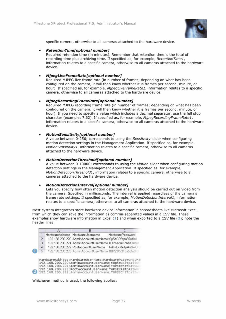
Milestone XProtect Professional 7.0; Administrator’s Manual
www.milestonesys.com Page 37 Wizards
specific camera, otherwise to all cameras attached to the hardware device.
RetentionTime[optional number]
Required retention time (in minutes). Remember that retention time is the total of recording time plus archiving time. If specified as, for example, RetentionTime1, information relates to a specific camera, otherwise to all cameras attached to the hardware device.
MjpegLiveFrameRate[optional number] Required MJPEG live frame rate (in number of frames; depending on what has been configured on the camera, it will then know whether it is frames per second, minute, or
hour). If specified as, for example, MjpegLiveFrameRate1, information relates to a specific camera, otherwise to all cameras attached to the hardware device.
MjpegRecordingFrameRate[optional number]
Required MJPEG recording frame rate (in number of frames; depending on what has been configured on the camera, it will then know whether it is frames per second, minute, or hour). If you need to specify a value which includes a decimal separator, use the full stop character (example: 7.62). If specified as, for example, MjpegRecordingFrameRate1, information relates to a specific camera, otherwise to all cameras attached to the hardware device.
MotionSensitivity[optional number] A value between 0-256; corresponds to using the Sensitivity slider when configuring motion detection settings in the Management Application. If specified as, for example,
MotionSensitivity1, information relates to a specific camera, otherwise to all cameras
attached to the hardware device.
MotionDetectionThreshold[optional number] A value between 0-10000; corresponds to using the Motion slider when configuring motion
detection settings in the Management Application. If specified as, for example, MotionDetectionThreshold1, information relates to a specific camera, otherwise to all cameras attached to the hardware device.
MotionDetectionInterval[optional number]
Lets you specify how often motion detection analysis should be carried out on video from the camera. Specified in milliseconds. The interval is applied regardless of the camera’s frame rate settings. If specified as, for example, MotionDetectionInterval1, information relates to a specific camera, otherwise to all cameras attached to the hardware device.
Most system integrators store hardware device information in spreadsheets like Microsoft Excel,
from which they can save the information as comma-separated values in a CSV file. These examples show hardware information in Excel (1) and when exported to a CSV file (2); note the header lines:
Whichever method is used, the following applies:
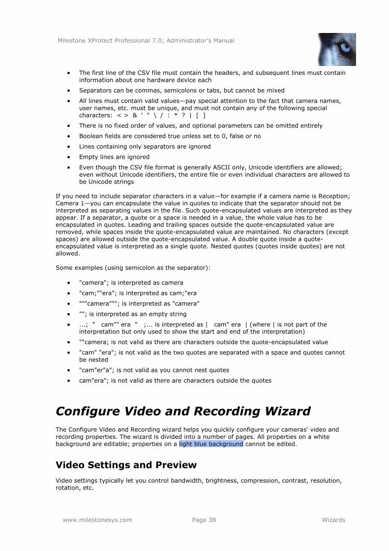
Milestone XProtect Professional 7.0; Administrator’s Manual
www.milestonesys.com Page 38 Wizards
The first line of the CSV file must contain the headers, and subsequent lines must contain
information about one hardware device each
Separators can be commas, semicolons or tabs, but cannot be mixed
All lines must contain valid values—pay special attention to the fact that camera names,
user names, etc. must be unique, and must not contain any of the following special characters: < > & ' " \ / : * ? | [ ]
There is no fixed order of values, and optional parameters can be omitted entirely
Boolean fields are considered true unless set to 0, false or no
Lines containing only separators are ignored
Empty lines are ignored
Even though the CSV file format is generally ASCII only, Unicode identifiers are allowed;
even without Unicode identifiers, the entire file or even individual characters are allowed to be Unicode strings
If you need to include separator characters in a value—for example if a camera name is Reception; Camera 1—you can encapsulate the value in quotes to indicate that the separator should not be interpreted as separating values in the file. Such quote-encapsulated values are interpreted as they appear. If a separator, a quote or a space is needed in a value, the whole value has to be encapsulated in quotes. Leading and trailing spaces outside the quote-encapsulated value are removed, while spaces inside the quote-encapsulated value are maintained. No characters (except
spaces) are allowed outside the quote-encapsulated value. A double quote inside a quote-encapsulated value is interpreted as a single quote. Nested quotes (quotes inside quotes) are not
allowed. Some examples (using semicolon as the separator):
"camera"; is interpreted as camera
"cam;""era"; is interpreted as cam;"era
"""camera"""; is interpreted as "camera"
""; is interpreted as an empty string
...; " cam"" era " ;... is interpreted as | cam" era | (where | is not part of the interpretation but only used to show the start and end of the interpretation)
""camera; is not valid as there are characters outside the quote-encapsulated value
"cam" "era"; is not valid as the two quotes are separated with a space and quotes cannot
be nested
"cam"er"a"; is not valid as you cannot nest quotes
cam"era"; is not valid as there are characters outside the quotes
Configure Video and Recording Wizard
The Configure Video and Recording wizard helps you quickly configure your cameras' video and
recording properties. The wizard is divided into a number of pages. All properties on a white background are editable; properties on a light blue background cannot be edited.
Video Settings and Preview
Video settings typically let you control bandwidth, brightness, compression, contrast, resolution, rotation, etc.
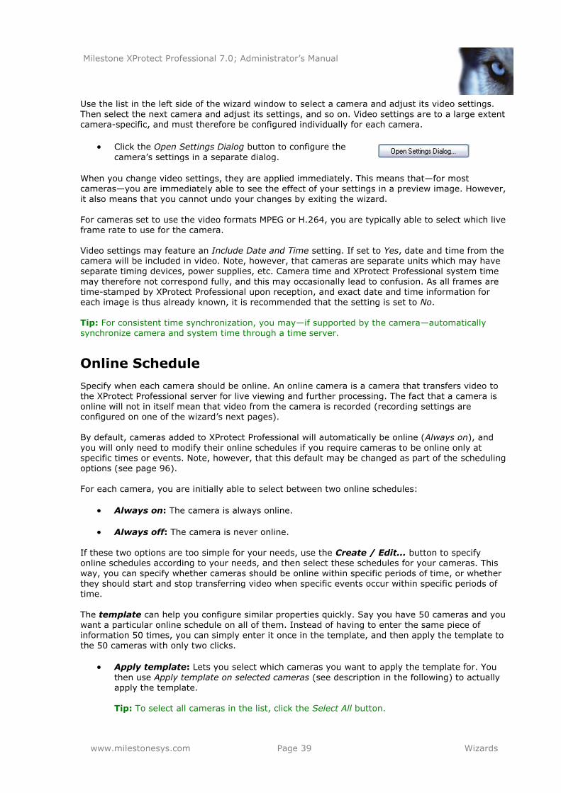
Milestone XProtect Professional 7.0; Administrator’s Manual
www.milestonesys.com Page 39 Wizards
Use the list in the left side of the wizard window to select a camera and adjust its video settings. Then select the next camera and adjust its settings, and so on. Video settings are to a large extent camera-specific, and must therefore be configured individually for each camera.
Click the Open Settings Dialog button to configure the
camera’s settings in a separate dialog.
When you change video settings, they are applied immediately. This means that—for most cameras—you are immediately able to see the effect of your settings in a preview image. However, it also means that you cannot undo your changes by exiting the wizard.
For cameras set to use the video formats MPEG or H.264, you are typically able to select which live frame rate to use for the camera. Video settings may feature an Include Date and Time setting. If set to Yes, date and time from the camera will be included in video. Note, however, that cameras are separate units which may have separate timing devices, power supplies, etc. Camera time and XProtect Professional system time
may therefore not correspond fully, and this may occasionally lead to confusion. As all frames are time-stamped by XProtect Professional upon reception, and exact date and time information for each image is thus already known, it is recommended that the setting is set to No. Tip: For consistent time synchronization, you may—if supported by the camera—automatically synchronize camera and system time through a time server.
Online Schedule
Specify when each camera should be online. An online camera is a camera that transfers video to the XProtect Professional server for live viewing and further processing. The fact that a camera is online will not in itself mean that video from the camera is recorded (recording settings are configured on one of the wizard’s next pages). By default, cameras added to XProtect Professional will automatically be online (Always on), and
you will only need to modify their online schedules if you require cameras to be online only at specific times or events. Note, however, that this default may be changed as part of the scheduling options (see page 96). For each camera, you are initially able to select between two online schedules:
Always on: The camera is always online.
Always off: The camera is never online.
If these two options are too simple for your needs, use the Create / Edit... button to specify online schedules according to your needs, and then select these schedules for your cameras. This way, you can specify whether cameras should be online within specific periods of time, or whether they should start and stop transferring video when specific events occur within specific periods of time.
The template can help you configure similar properties quickly. Say you have 50 cameras and you want a particular online schedule on all of them. Instead of having to enter the same piece of information 50 times, you can simply enter it once in the template, and then apply the template to the 50 cameras with only two clicks.
Apply template: Lets you select which cameras you want to apply the template for. You
then use Apply template on selected cameras (see description in the following) to actually apply the template. Tip: To select all cameras in the list, click the Select All button.
Milestone XProtect Professional 7.0; Administrator’s Manual
www.milestonesys.com Page 40 Wizards
Select All: Click button to select all cameras in the Apply Template column.
Clear All: Click button to clear all selections in the Apply Template column.
Apply template on selected cameras: Lets you apply the value from the template to selected cameras.
Live and Recording Settings (Motion-JPEG Cameras)
This wizard page only appears if one or more of your cameras use the MJPEG video format.
Specify which frame rates to use for each camera. You can also select pre- and post-recording, allowing you to store recordings from periods preceding and following detected motion and/or specified events. How does pre- and post-recording work? XProtect Professional receives video in a continuous stream from the camera whenever the camera is enabled and scheduled to be online. This is what
lets you view live video, but it also means that XProtect Professional can easily store received video for a number of seconds in its memory (a.k.a. buffering). If it turns out that the buffered video is needed for pre- or post-recording, it is automatically appended to the recording. If not, it is simply discarded.
Live Frame Rate: Frame rate for live video from the camera. Select required number of
frames per second.
Recording Frame Rate: Frame rate for recorded video from the camera. Select required
number of frames per second.
Record on: Lets you select under which conditions video from the camera should be recorded:
o Always: Record whenever the camera is enabled (see page 67) and scheduled to
be online (see page 98). The latter allows for time-based recording.
o Never: Never record. Live video will be displayed, but—since no video is kept in the database—users will not be able to play back video from the camera.
o Motion Detection: Select this to record video in which motion (see page 74) is detected. Unless post-recording (see the following) is used, recording will stop immediately after the last motion is detected.
o Event: Only available for individual cameras which have already been configured to be able to record on events; this option is never available in the template. Select
this to use the camera’s existing events-based recording configuration. Read more about events on page 107.
o Motion Detection & Event: Only available for individual cameras which have
already been configured to be able to record on events; this option is never available in the template. Select this to use the camera’s existing motion- and events-based recording configuration.
Pre-recording: You can store recordings from periods preceding detected motion and/or start events. Select check box to enable this feature. Remember to specify required number of seconds in the neighboring column.
Seconds [of pre-recording]: Specify the number of seconds for which you want to record video from before recording start conditions (that is motion or start event) are met. Usually, only some seconds of pre-recording is required, but you can specify up to 65535
seconds of pre-recording, corresponding to 18 hours, 12 minutes and 15 seconds.
Milestone XProtect Professional 7.0; Administrator’s Manual
www.milestonesys.com Page 41 Wizards
However, if specifying a very long pre-recording time, you can potentially run into a scenario where your pre-recording time spans scheduled or unscheduled archiving times (you define these on one of the wizard’s next pages). That can be problematic since pre-
recording does not work well during archiving.
Post-recording: You can store recordings from periods following detected motion and/or stop events. Select check box to enable this feature. Remember to specify required number
of seconds in the neighboring column.
Seconds [of post-recording]: Specify the number of seconds for which you want to record video from after recording stop conditions (that is motion or stop event) are met.
Usually, only some seconds of post-recording is required, but you can specify up to 65535 seconds of post-recording, corresponding to 18 hours, 12 minutes and 15 seconds. However, if specifying a very long post-recording time, you can potentially run into a scenario where your post-recording time spans scheduled or unscheduled archiving times (you define these on one of the wizard’s next pages). That can be problematic since post-recording does not work well during archiving.
The template can help you configure similar properties quickly. Say you have 50 cameras and you want a particular frame rate on all of them. Instead of having to enter the same piece of information 50 times, you can simply enter it once in the template, and then apply the template to the 50 cameras with only two clicks.
Apply template: Lets you select which cameras you want to apply the template for. You
then use Apply template on selected cameras (see description in the following) to actually
apply the template. Tip: To select all cameras in the list, click the Select All button.
Select All: Click button to select all cameras in the Apply Template column.
Clear All: Click button to clear all selections in the Apply Template column.
Apply template on selected cameras: Lets you apply the value from the template to
selected cameras.
Live and Recording Settings (MPEG Cameras)
This wizard page only appears if one or more of your cameras use the MPEG video format. Specify which frame rate to use for each camera, and whether to record all frames or keyframes only. You can also select pre- and post-recording, allowing you to store recordings from periods preceding and following detected motion and/or specified events.
How does pre- and post-recording work? XProtect Professional receives video in a continuous stream from the camera whenever the camera is enabled and scheduled to be online. This is what lets you view live video, but it also means that XProtect Professional can easily store received video for a number of seconds in its memory (a.k.a. buffering). If it turns out that the buffered video is needed for pre- or post-recording, it is automatically appended to the recording. If not, it is simply discarded.
Live Frame Rate: Frame rate for live video from the camera. Select required number of frames per second.
Record Keyframes Only: Keyframes stored at specified intervals record the entire view of the camera, whereas the frames between keyframes record only pixels that change; this helps greatly reduce the size of MPEG files. Select the check box if you only want to record keyframes.
Milestone XProtect Professional 7.0; Administrator’s Manual
www.milestonesys.com Page 42 Wizards
Record on: Lets you select under which conditions video from the camera should be
recorded:
o Always: Record whenever the camera is enabled (see page 67) and scheduled to be online (see page 98). The latter allows for time-based recording.
o Never: Never record. Live video will be displayed, but—since no video is kept in
the database—users will not be able to play back video from the camera.
o Motion Detection: Select this to record video in which motion (see page 74) is detected. Unless post-recording (see the following) is used, recording will stop
immediately after the last motion is detected.
o Event: Only available for individual cameras which have already been configured to
be able to record on events; this option is never available in the template. Select this to use the camera’s existing events-based recording configuration. Read more about events on page 107.
o Motion Detection & Event: Only available for individual cameras which have
already been configured to be able to record on events; this option is never
available in the template. Select this to use the camera’s existing motion- and events-based recording configuration.
Pre-recording: You can store recordings from periods preceding detected motion and/or
start events. Select check box to enable this feature. Remember to specify required
number of seconds in the neighboring column.
Seconds [of pre-recording]: Specify the number of seconds for which you want to record video from before recording start conditions (that is motion or start event) are met.
Usually, only some seconds of pre-recording is required, but you can specify up to 65535 seconds of pre-recording, corresponding to 18 hours, 12 minutes and 15 seconds. However, if specifying a very long pre-recording time, you can potentially run into a scenario where your pre-recording time spans scheduled or unscheduled archiving times (you define these on one of the wizard’s next pages). That can be problematic since pre-recording does not work well during archiving.
Post-recording: You can store recordings from periods following detected motion and/or stop events. Select check box to enable this feature. Remember to specify required number of seconds in the neighboring column.
Seconds [of post-recording]: Specify the number of seconds for which you want to record video from after recording stop conditions (that is motion or stop event) are met. Usually, only some seconds of post-recording is required, but you can specify up to 65535
seconds of post-recording, corresponding to 18 hours, 12 minutes and 15 seconds. However, if specifying a very long post-recording time, you can potentially run into a scenario where your post-recording time spans scheduled or unscheduled archiving times (you define these on one of the wizard’s next pages). That can be problematic since post-recording does not work well during archiving.
The template can help you configure similar properties quickly. Say you have 50 cameras and you
want a particular frame rate on all of them. Instead of having to enter the same piece of information 50 times, you can simply enter it once in the template, and then apply the template to the 50 cameras with only two clicks.
Apply template: Lets you select which cameras you want to apply the template for. You
then use Apply template on selected cameras (see description in the following) to actually apply the template. Tip: To select all cameras in the list, click the Select All button.
Milestone XProtect Professional 7.0; Administrator’s Manual
www.milestonesys.com Page 43 Wizards
Select All: Click button to select all cameras in the Apply Template column.
Clear All: Click button to clear all selections in the Apply Template column.
Apply template on selected cameras: Lets you apply the value from the template to selected cameras.
Drive Selection
Specify which drives you want to store cameras' recordings on. You can specify separate drives/paths for recording and archiving.
What is archiving? Archiving—an integrated and automated feature—helps you store recordings beyond the capabilities of XProtect Professional’s standard database. Archiving thus maximizes storage capacity and minimizes risk. For more detailed information, see page 85.
Drive: Letter representing the drive in question, for example C:. To add further network
drives, use the Network drive field (described in the following).
Purpose: Lets you select what you want to use the drive for:
o Not in use: Do not use the drive.
o Recording: Only available if the drive is a local drive on the XProtect Professional server; network drives cannot be used for recording. Use the drive for storing recordings in XProtect Professional’s regular database.
o Archiving: Use the drive for archiving. For archiving, it is generally a good idea to
use a drive which has plenty of space.
Tip: With dynamic path selection for archives (see description in the following), you do not have to worry about drive space.
o Rec. & Archiving: Only available if the drive is a local drive on the XProtect
Professional server; network drives cannot be used for recording. Use the drive for storing recordings in XProtect Professional’s regular database as well as for archiving.
Recording Path: Path to the folder in which to store recordings in XProtect Professional’s
regular database. Default is [drive letter]:\MediaDatabase. To browse for another folder, click the browse icon next to the required cell. You are only able to specify a path to a folder on the selected drive (which must be a local drive). If you change the recording path, and there are existing recordings at the old location, you will be asked whether you
want to move the recordings to the new location (recommended), leave them at the old location, or delete them.
Archiving Path: Only editable if not using dynamic path selection for archives (see
description in the following). Path to the folder in which archived recordings should be stored. To browse for another folder, click the browse icon next to the required cell. You can specify a path to local or networked drive as required. If you change the archiving path, and there are existing archived recordings at the old location, you will be asked
whether you want to move the archived recordings to the new location (recommended), leave them at the old location, or delete them.
Total Size: Total size of the drive.
Free Space: Amount of unused space left on the drive.
Milestone XProtect Professional 7.0; Administrator’s Manual
www.milestonesys.com Page 44 Wizards
Dynamic path selection for archives: If using this option (highly recommended), you
should select a number of different drives for archiving. If the path containing the XProtect Professional database is on one of the drives you have selected for archiving, XProtect Professional will always try to archive to that drive first. If not, XProtect Professional automatically archives to the archiving drive with the most available space at any time, provided there is not a camera database using that drive. Which drive has the most available space may change during the archiving process, and archiving may therefore
happen to several archiving drives during the same process. This fact will have no impact on how users find and view archived recordings.
Network Drive: Lets you add a network drive to the list of drives. First specify the
network drive, then click the Add button (the button becomes available when you specify a network drive). Note that network drives cannot be used for recording, only for archiving.
Archiving schedule: Lets you specify when you want XProtect Professional to
automatically move recordings to your archiving path(s). You can specify up to 24 archiving times per day, with minimum one hour between each one. As a rule of thumb, the more you expect to record, the more often you should archive.
Recording and Archiving Settings
Select recording and archiving paths for each individual camera. What is archiving? Archiving—an integrated and automated feature—helps you store recordings
beyond the capabilities of XProtect Professional’s standard database. Archiving thus maximizes storage capacity and minimizes risk. For more detailed information, see page 85.
Recording Path: Path to the folder in which to store the camera’s recordings in XProtect
Professional’s regular database. Default is C:\MediaDatabase. If you specified several recording paths on the wizard’s previous page, you can select between those paths.
Archiving Path: Path to the folder in which archived recordings should be stored. Only
relevant if not using dynamic path selection for archives.
Retention Time: Total amount of time for which you want to keep recordings from the camera (that is recordings in XProtect Professional’s database as well as any archived
recordings).
Note that the retention time covers the total amount of time you want to keep recordings for; in earlier XProtect Professional versions time limits were specified separately for the database and archives.
The template can help you configure similar properties quickly. Say you have 50 cameras and you
want a particular recording path for all of them. Instead of having to enter the same piece of information 50 times, you can simply enter it once in the template, and then apply the template to the 50 cameras with only two clicks.
Apply template: Lets you select which cameras you want to apply the template for. You
then use Apply template on selected cameras (see description in the following) to actually apply the template.
Tip: To select all cameras in the list, click the Select All button.
Select All: Click button to select all cameras in the Apply Template column.
Clear All: Click button to clear all selections in the Apply Template column.
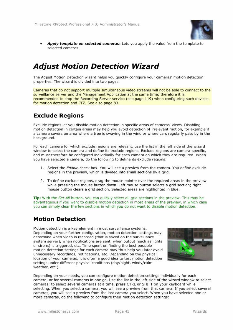
Milestone XProtect Professional 7.0; Administrator’s Manual
www.milestonesys.com Page 45 Wizards
Apply template on selected cameras: Lets you apply the value from the template to
selected cameras.
Adjust Motion Detection Wizard
The Adjust Motion Detection wizard helps you quickly configure your cameras' motion detection properties. The wizard is divided into two pages.
Cameras that do not support multiple simultaneous video streams will not be able to connect to the surveillance server and the Management Application at the same time; therefore it is recommended to stop the Recording Server service (see page 119) when configuring such devices for motion detection and PTZ. See also page 83.
Exclude Regions
Exclude regions let you disable motion detection in specific areas of cameras' views. Disabling motion detection in certain areas may help you avoid detection of irrelevant motion, for example if
a camera covers an area where a tree is swaying in the wind or where cars regularly pass by in the background. For each camera for which exclude regions are relevant, use the list in the left side of the wizard
window to select the camera and define its exclude regions. Exclude regions are camera-specific, and must therefore be configured individually for each camera on which they are required. When
you have selected a camera, do the following to define its exclude regions:
1. Select the Enable check box. You will see a preview from the camera. You define exclude regions in the preview, which is divided into small sections by a grid.
2. To define exclude regions, drag the mouse pointer over the required areas in the preview while pressing the mouse button down. Left mouse button selects a grid section; right
mouse button clears a grid section. Selected areas are highlighted in blue. Tip: With the Set All button, you can quickly select all grid sections in the preview. This may be advantageous if you want to disable motion detection in most areas of the preview, in which case you can simply clear the few sections in which you do not want to disable motion detection.
Motion Detection
Motion detection is a key element in most surveillance systems.
Depending on your further configuration, motion detection settings may determine when video is recorded (that is saved on the surveillance system server), when notifications are sent, when output (such as lights or sirens) is triggered, etc. Time spent on finding the best possible motion detection settings for each camera may thus help you later avoid unnecessary recordings, notifications, etc. Depending on the physical location of your cameras, it is often a good idea to test motion detection
settings under different physical conditions (day/night, windy/calm weather, etc.).
Depending on your needs, you can configure motion detection settings individually for each camera, or for several cameras in one go. Use the list in the left side of the wizard window to select cameras; to select several cameras at a time, press CTRL or SHIFT on your keyboard while
selecting. When you select a camera, you will see a preview from that camera. If you select several cameras, you will see a preview from the last camera you select. When you have selected one or more cameras, do the following to configure their motion detection settings:
Milestone XProtect Professional 7.0; Administrator’s Manual
www.milestonesys.com Page 46 Wizards
1. Note any green areas in the preview. Green areas are areas with motion.
2. Adjust the Sensitivity slider so that irrelevant background noise is filtered out, and only real
motion is shown in green. As an alternative to using the slider, you may specify a value between 0 and 256 in the field next to the slider to control the sensitivity setting.
Tip: Technically, the slider determines how much each pixel must change before it is
regarded as motion. With a high sensitivity, very little change in a pixel is required before it is regarded as motion. If you find the concept of sensitivity difficult to grasp, try dragging
the slider to the left: The more you drag the slider to the left, the more of the preview becomes green. This is because with a high sensitivity even the slightest change in a pixel will be regarded as motion.
3. Adjust the Motion slider so that motion detection is only triggered by the required level of
motion. The selected motion level is indicated by the black vertical line in the Motion level bar above the sliders. The black vertical line serves as a threshold: When motion is above (that is to the right of) the selected level, the bar changes color from green to red, indicating a positive motion detection. As an alternative to using the slider, you may specify a value between 0 and 10000 in the field next to the slider to control the motion setting.
Tip: Technically, the slider determines how many pixels must change before it is regarded
as motion. The more you drag the slider to the left, the fewer pixels must change before you have a positive motion detection. Thus, as a rule of thumb, the more you drag the slider to the left, the more positive motion detections you are likely to get since less change will be required to trigger a positive motion detection. The number of positive
motion detections may subsequently affect the amount of video you record, the amount of notifications you receive, etc.
4. Motion detection is vital on most surveillance systems, but also consumes system
resources on the surveillance server. In the Detection interval field, you are therefore able to specify how often motion detection analysis should be carried out on video from the camera. Default is every 240 milliseconds (that is close to once every quarter of a second).
The interval is applied regardless of your cameras' frame rate settings.
Motion Detection and PTZ Cameras
Motion detection generally works the same way for PTZ (Pan/Tilt/Zoom) cameras as it does for regular cameras. However:
It is not possible to configure motion detection separately for each of a PTZ camera’s
preset positions.
In order not to activate unwanted recording, notifications, etc., motion detection is
automatically disabled while a PTZ camera moves between two preset positions. After a number of seconds—the so-called transition time, specified as part of the PTZ camera’s PTZ patrolling properties (see page 79)—motion detection is automatically enabled again.
Configure User Access Wizard
The Configure User Access wizard helps you quickly configure clients' access to the XProtect
Professional server as well as which users should be able to use clients.
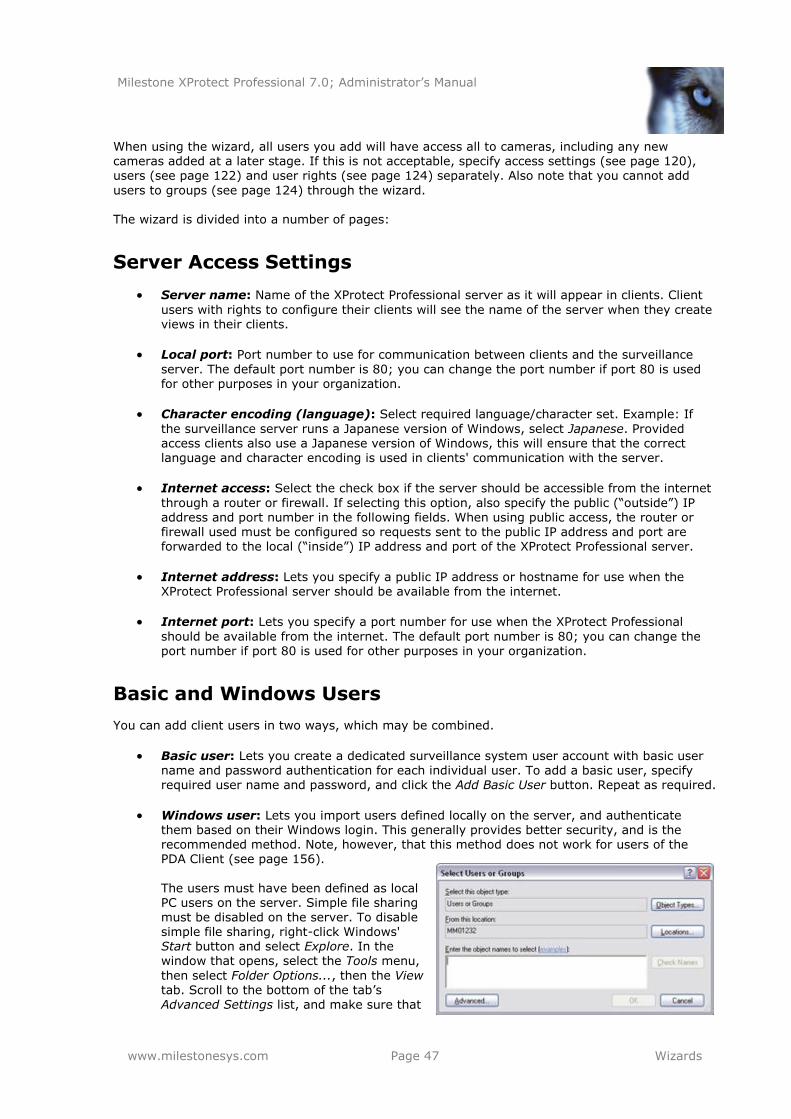
Milestone XProtect Professional 7.0; Administrator’s Manual
www.milestonesys.com Page 47 Wizards
When using the wizard, all users you add will have access all to cameras, including any new cameras added at a later stage. If this is not acceptable, specify access settings (see page 120), users (see page 122) and user rights (see page 124) separately. Also note that you cannot add
users to groups (see page 124) through the wizard. The wizard is divided into a number of pages:
Server Access Settings
Server name: Name of the XProtect Professional server as it will appear in clients. Client
users with rights to configure their clients will see the name of the server when they create views in their clients.
Local port: Port number to use for communication between clients and the surveillance
server. The default port number is 80; you can change the port number if port 80 is used for other purposes in your organization.
Character encoding (language): Select required language/character set. Example: If
the surveillance server runs a Japanese version of Windows, select Japanese. Provided access clients also use a Japanese version of Windows, this will ensure that the correct language and character encoding is used in clients' communication with the server.
Internet access: Select the check box if the server should be accessible from the internet
through a router or firewall. If selecting this option, also specify the public (―outside‖) IP address and port number in the following fields. When using public access, the router or firewall used must be configured so requests sent to the public IP address and port are forwarded to the local (―inside‖) IP address and port of the XProtect Professional server.
Internet address: Lets you specify a public IP address or hostname for use when the XProtect Professional server should be available from the internet.
Internet port: Lets you specify a port number for use when the XProtect Professional
should be available from the internet. The default port number is 80; you can change the port number if port 80 is used for other purposes in your organization.
Basic and Windows Users
You can add client users in two ways, which may be combined.
Basic user: Lets you create a dedicated surveillance system user account with basic user name and password authentication for each individual user. To add a basic user, specify required user name and password, and click the Add Basic User button. Repeat as required.
Windows user: Lets you import users defined locally on the server, and authenticate them based on their Windows login. This generally provides better security, and is the recommended method. Note, however, that this method does not work for users of the PDA Client (see page 156).
The users must have been defined as local PC users on the server. Simple file sharing
must be disabled on the server. To disable simple file sharing, right-click Windows' Start button and select Explore. In the window that opens, select the Tools menu,
then select Folder Options..., then the View tab. Scroll to the bottom of the tab’s Advanced Settings list, and make sure that
Milestone XProtect Professional 7.0; Administrator’s Manual
www.milestonesys.com Page 48 Wizards
the Use simple file sharing (Recommended) check box is cleared. When ready, click OK and close the window.
Add Windows users the following way:
1. Click the Add Windows User... button. This will open the Select Users or Groups window. Note that you will only be able to make selections from the local computer, even if
you click the Locations... button.
2. In the Enter the object names to select box, type the required user names, then use the Check Names feature to verify that the user names you have entered are recognized. Example: Brian; Hannah; Karen; Wayne
3. When ready, click OK.
When a user who has been added from a local database this way logs in with a client, the user should not specify any server name, PC name, or IP address as part of the user name.
● Example of a correctly specified user name: USER001.
● Example of an incorrectly specified user name: PC001/USER001.
The user should of course still specify a password and any required server information.
Access Summary
The access summary simply lists which cameras your users will have access to. When using the wizard, all users you have added will have access all to cameras, including any new cameras added at a later stage. You can, however, limit individual users' access to cameras by changing their individual rights (see page 124).
Replace Hardware Device Wizard
The Replace Hardware wizard helps you replace a hardware device—which you have previously
added to and configured on your surveillance system—with a new one. This can typically be relevant if you replace a physical camera on your network. The Replace Hardware Device wizard helps you through the entire replacement process on the surveillance system server, including:
Detecting the new hardware device
Specifying license for the new hardware device
Deciding what to do with existing recordings from the old hardware device You access the Replace Device Hardware wizard from the Management Application’s navigation
pane: Expand Advanced Configuration, expand Hardware Devices, right-click the hardware device you want to replace, and select Replace Hardware Device. You can access also the wizard when dealing with a hardware device’s Network, Device Type & License properties (see page 53).
Remember that you must have a Device License Key (DLK) for every hardware device (cameras, etc.) you intend to use on your XProtect Professional system. Before using the wizard, make sure you have a DLK for the new hardware device.
The wizard is divided into two pages:
Milestone XProtect Professional 7.0; Administrator’s Manual
www.milestonesys.com Page 49 Wizards
New Hardware Device Information
First specify details about the new hardware device:
Hardware device address: IP address or host name of the new hardware device.
Hardware device port: Port number to use for communicating with the hardware device.
Default is port 80. If the new hardware device is located behind a NAT-enabled router or a firewall, you may need to specify a different port number. When this is the case, also remember to configure the router/firewall so it maps the port and IP addresses used by the
new hardware device.
User name: User name for the hardware device’s administrator account. Many organizations use the hardware device manufacturer’s default user names for their hardware devices. If that is the case in your organization, select <default> (do not type a manufacturer’s default user name as this can be a source of error; trust that XProtect
Professional will know the manufacturer’s default user name). Other typical user names, such as admin or root are also selectable from the list. If requiring a user name which is not on the list, simply type the required user name.
Tip: User names you type yourself will subsequently be added to the list, so you can easily select them later.
Password: Password required for accessing the new hardware device’s administrator
account. Tip: If in doubt about which user name/password to use, ask yourself: Have you previously
used a web page to connect to the hardware device and view video? While you did this, were you also able to configure camera settings, such as resolution, etc.? If you can answer yes to both questions, you were in all likelihood using the hardware device’s administrator account, in which case you will also know the user name/password. Tip: If you are still in doubt, look in the Device Pack Release Notes, available from the Downloads section of www.milestonesys.com. This will show you the administrator account
user name for each supported hardware device. For obvious reasons it will not show you the password.
Then specify which device driver to use for the new hardware device. You can do this in two ways:
By selecting the required video device driver in the Hardware device type list, then
clicking the Auto-detect/Verify Hardware Device Type button to verify that the driver matches the hardware device. - or -
By just clicking the Auto-detect/Verify Hardware Device Type button to automatically detect and verify the right driver.
When the right driver is found, the Serial number (MAC address) field will display the MAC
address of the new hardware device. The Device License Key (DLK) required to use the hardware device is issued based on this MAC address.
If you have already imported a .dlk file which includes the DLK for the new hardware device, the Device license key (DLK) field will be pre-filled. If not, you can either enter the DLK for the new device manually in the field, or click the Import DLKs button to import a .dlk file (see page 52)
which includes the DLK for the new hardware device. When ready, click Next.
Milestone XProtect Professional 7.0; Administrator’s Manual
www.milestonesys.com Page 50 Wizards
Database Action
The last page of the Replace Hardware wizard lets you decide what to do with the camera and the database containing recordings from the camera attached to the old hardware device. For multi-
camera devices such as video encoders, you must decide what to do for each video channel on the new hardware device. The table in the left side of the wizard page lists available video channels on the new hardware device. For a regular single-camera hardware device, there will only be one video channel. For video encoders, there will typically be several video channels.
1. For each video channel, use the table’s Inherit column to select which camera from the old hardware device should be inherited by the new hardware device.
2. Then decide what to do with camera databases. You have three options:
Inherit existing database(s): The cameras you selected to be inherited by the
new hardware device will inherit camera names, recordings databases as well as any archives from the old hardware device. Databases and archives (see page 85) will be renamed to reflect the new hardware device’s MAC address and video channels. The rights (see page 124) of users with access to the inherited cameras
are automatically updated so they can view both old and new recordings. Users will basically not notice the hardware device replacement since camera names will remain the same.
Delete the existing database(s): The databases of the cameras you selected to
be inherited by the new hardware device will be deleted. New databases will be created for future recordings, but it will not be possible to view recordings from before the hardware replacement.
Leave the existing database(s): The databases of the cameras you selected to
be inherited by the new hardware device will not be deleted. New databases will be created for future recordings, but even though the old databases still exist on the XProtect Professional server it will not be possible to view recordings from before the hardware replacement. Should you later want to delete the old databases, deletion must take place manually.
3. If the new hardware device has fewer video channels than the old hardware device, it will
not be possible for the new hardware device to inherit all cameras from the old hardware device. When that is the case, you will be asked what to do with the databases of cameras that could not be inherited by the new hardware device. You have two options:
Delete the databases for the cameras that are not inherited: The databases
of the cameras that could not be inherited by the new hardware devices will be deleted. It will not be possible to view recordings from before the hardware replacement. New databases will of course be created for future recordings by the new hardware devices.
Leave the databases for the cameras that are not inherited: The databases of the cameras that could not be inherited by the new hardware devices will not be deleted. Even though the old databases still exist on the XProtect Professional
server it will not be possible to view recordings from before the hardware
replacement. Should you later want to delete the old databases, deletion must take place manually. New databases will of course be created for future recordings by the new hardware devices.
4. Click Finish.

Milestone XProtect Professional 7.0; Administrator’s Manual
www.milestonesys.com Page 51 Wizards
5. When ready, restart the Recording Server service (see page 119). The hardware replacement will not be evident in clients until you restart the Recording Server service.
Milestone XProtect Professional 7.0; Administrator’s Manual
www.milestonesys.com Page 52 Licenses
Licenses
You must have a Device License Key (DLK) for every hardware device (cameras, etc.) on your XProtect Professional system.
Remember that you are allowed to install and use only the number of cameras covered by your license agreement; regardless of your number of available DLKs. For example, a fully used four-port video encoder counts as four cameras; it will thus use four licenses even though its four
cameras are connected through a single hardware device. You get DLKs as part of the software registration process on the Milestone website,
www.milestonesys.com. Upon registration, all your DLKs are sent to you as a single .dlk file attached to an e-mail. Often, your XProtect Professional vendor will take care of the process for you; in which case all you have to do is import the .dlk file you receive by e-mail.
Import DLKs (Device License Keys)
Importing the file is quick and easy, and it will free you from having to specify license keys manually for each hardware device later.
1. When you receive the e-mail, save the attached .dlk file at a location accessible from the XProtect Professional server, for example on a network drive or on a USB stick.
2. In the Management Application’s File menu, select Import DLKs... (or click the Import DLKs button if you are working with the Add Hardware Devices wizard (see page 26)).
If you need to import DLKs in connection with an upgrade of your XProtect Professional software version, always use the File > Import DLKs… method.
3. Browse to the location at which you have saved the received .dlk file, select the file, and
click Open. All DLKs are now imported into XProtect Professional, and will be available when you add cameras and other hardware (see page 26).
Specify a New SLC (Software License Code)
If you have upgraded your XProtect Professional or otherwise acquired a new Software License Code (SLC), do the following to use the new SLC:
1. In the Management Application’s Help menu, select About...
2. In the Software License Code (SLC) field, overwrite the old SLC with the new SLC, and click OK.
3. Close the Management Application. When you open the Management Application again, the new SLC will take effect.
Milestone XProtect Professional 7.0; Administrator’s Manual
www.milestonesys.com Page 53 Hardware Devices
Hardware Devices
You add cameras and other hardware devices, such as video encoders, to your XProtect Professional system through the Add Hardware Devices wizard (see page 26). If microphones
and/or speakers are attached to a hardware device, they are automatically added as well. You are allowed to use up to 64 cameras per XProtect Professional server. Note that, if required, it is possible to add more cameras than you are allowed to use. If using video encoder devices on
your system, bear in mind that many video encoder devices have more than one camera connected to them. For example, a fully used four-port video encoder will count as four cameras.
Configuration
Once you have added hardware devices, you can specify/edit device-specific properties, such as the IP address, which video channels to use, which COM ports to use for controlling attached PTZ (Pan/Tilt/Zoom) cameras, whether to use fisheye technology, etc.:
1. In the Management Application’s navigation pane, expand Advanced Configuration, expand Hardware Devices, right-click the required hardware device, and select Properties.
2. Specify Name & Video Channels, Network, Device Type & License, PTZ Device, and Fisheye properties as required. All of the properties are described in the following.
3. Save your configuration changes by clicking the Save Configuration button in the Management Application’s toolbar.
Name & Video Channels
Hardware name: Name of the hardware device as it will appear in the Management Application. If required, you can overwrite the existing hardware device name with a new one. Hardware device names must be unique, and must not contain any of the following special characters: < > & ' " \ / : * ? | [ ]
Video channel # enabled: Lets you enable/disable each of the selected hardware device’s video channels. Many hardware devices only have a single video channel, in which case only one channel will be listed. Other hardware devices—typically video encoder
devices—have several video channels.
Why are some of the channels unavailable? This will be the case if you are not licensed to use all of a video encoder device’s channels. Example: You have a video encoder device with four channels, but your license for the device only allows you to use two of them. In that case, you will only be able to have two channels enabled at a time; the two other channels will be disabled. Note that you are free to select which two channels
you want to enable. Contact your Milestone vendor if you need to change your number of licenses.
Network, Device Type & License
Address: IP address or host name of the hardware device.
Milestone XProtect Professional 7.0; Administrator’s Manual
www.milestonesys.com Page 54 Hardware Devices
HTTP port: Port to use for HTTP communication with the hardware device. Default is port
80. To use the default port, select Use default HTTP port.
FTP port: Port to use for FTP communication with the hardware device. Default is port 21.
To use the default port, select Use default FTP port.
User name: User name for the hardware device’s administrator account. Many organizations use the hardware device manufacturer’s default user names for their hardware devices. If that is the case in your organization, select <default> (do not type a
manufacturer’s default user name as this can be a source of error; trust that XProtect Professional will know the manufacturer’s default user name). Other typical user names,
such as admin or root are also selectable from the list. If requiring a user name which is not on the list, simply type the required user name.
Tip: User names you type yourself will subsequently be added to the list, so you can easily
select them later.
Password: Password for the hardware device’s administrator account, a.k.a. the root password.
Hardware type: Read-only field displaying the type of video device driver used for communication with the hardware device.
Serial number (MAC address): Read-only field displaying the serial number of device.
The serial number is usually identical to the 12-character hexadecimal MAC address of the hardware device (example: 0123456789AF).
Device licence key (DLK): The 16-character license key (DLK) which gives you the right
to use the hardware device with XProtect Professional.
Replace Hardware Device: Opens a wizard (see page 48), with which you—if required—
can replace the selected hardware device with another one. This can typically be relevant if you replace a physical camera on your network. The wizard helps you take all relevant issues into account: finding the DLK for the new hardware device, deciding what to do with recordings from cameras attached to the old hardware device, etc.
PTZ Device
The PTZ Device properties are only available if configuring video encoder hardware devices on which the use of PTZ (Pan/Tilt/Zoom) cameras is possible.
Connected cameras have Pan/tilt/Zoom capabilities: Select check box if any of the
cameras attached to the video encoder device is a PTZ camera.
PTZ type on COM#: If a PTZ camera is controlled through the COM port (a.k.a. serial port) in question, select the required option. Options are device-specific, depending on
which PTZ protocols are used by the device in question. If no PTZ cameras are controlled through the COM port in question, select None.
Some of the options concern absolute and relative positioning. What is that? Absolute positioning is when the PTZ camera is controlled based on a single fixed position,
against which all other positions are measured. Relative positioning is when the PTZ camera is controlled relative to its current position.
The table in the lower half of the dialog contains a row for each video channel on the hardware device. First row from the top corresponds to video channel 1, second row from the top corresponds to video channel 2, etc.
Milestone XProtect Professional 7.0; Administrator’s Manual
www.milestonesys.com Page 55 Hardware Devices
Name: Name of the camera attached to the video channel in question.
Type: Lets you select whether the camera on the selected camera channel is fixed or moveable:
o Fixed: Camera is a regular camera mounted in a fixed position
o Moveable: Camera is a PTZ camera
Port: Available only if Moveable is selected in the Type column. Lets you select which COM
port on the video encoder to use for controlling the PTZ camera.
Port Address: Available only if Moveable is selected in the Type column. Lets you specify
port address of the camera. The port address will normally be 1. If using daisy chained PTZ cameras, the port address will identify each of them, and you should verify your settings with those recommended in the documentation for the camera.
Fisheye
Fisheye is a technology that allows viewing of 360-degree panoramic video through an advanced lens. If a camera attached to the hardware device is going to use fisheye, you must enable the technology and enter a special fisheye license key.
Enable fisheye: Select check box to enable use of the fisheye technology and specify further properties.
Fisheye license key: Enter your special fisheye license key. Only after you enter this key and click OK will it be possible to configure fisheye (see page 76) for camera(s) attached to the hardware device.
Where do I get the special fisheye license key? Contact your XProtect Professional vendor for further information.
Use Dedicated Input/Output Devices
It is possible to add a number of dedicated input/output (I/O) hardware devices to XProtect Professional. For information about which I/O hardware devices are supported, see the release
notes. When such I/O hardware devices are added, input on them can be used for generating events in XProtect Professional, and events in XProtect Professional can be used for activating output on the I/O hardware devices. This means that I/O hardware devices can be used in your events-based system setup in the same way as a camera.
When using some I/O hardware devices it is necessary for the surveillance system to regularly check the state of the hardware devices' input ports in order to detect whether input has been received. Such state checking at regular intervals is called polling. The interval between state checks, called a polling frequency, is specified as part of XProtect Professional’s general ports & polling properties (see page 108). For such I/O hardware devices, the polling frequency should be
set to the lowest possible value (one tenth of a second between state checks). For information about which I/O hardware devices require polling, see the release notes.
Milestone XProtect Professional 7.0; Administrator’s Manual
www.milestonesys.com Page 56 Hardware Devices
Replace a Hardware Device
If required, you can replace a hardware device—which you have previously added to and
configured on your surveillance system—with a new one. This can typically be relevant if you replace a physical camera on your network. The Replace Hardware Device wizard (see page 48) helps you through the entire replacement process on the surveillance system server, including:
Detecting the new hardware device
Specifying license for the new hardware device
Deciding what to do with existing recordings from the old hardware device
You access the replace Hardware wizard from the Management Application’s navigation pane: Expand Advanced Configuration, expand Hardware Devices, right-click the hardware device you want to replace, and select Replace Hardware Device. You can access also the wizard when dealing with a hardware device’s Network, Device Type & License properties (see page 53).
Delete a Hardware Device
IMPORTANT: Deleting a hardware device will not only delete all cameras, speakers and microphones attached to the hardware device. It will also delete any recordings from cameras on the hardware device.
1. In the Management Application’s navigation pane, expand Advanced Configuration, expand Hardware Devices, right-click the hardware device you want to delete, and select Delete
Hardware device.
2. Confirm that you want to delete the hardware device and all its recordings.
3. Save your configuration changes by clicking the Save Configuration button in the
Management Application’s toolbar.
4. Restart the Recording Server service (see page 119).
If you find that deleting a hardware device is not the right thing to do, consider disabling the individual cameras, speakers or microphones connected to the hardware device instead:
1. In the Management Application’s navigation pane, expand Advanced Configuration, expand Hardware Devices, and expand the hardware device in question.
2. Right-click the camera, microphone or speaker you want to disable, and select Disable.
3. Save your configuration changes by clicking the Save Configuration button in the
Management Application’s toolbar.
4. Restart the Recording Server service (see page 119).
Milestone XProtect Professional 7.0; Administrator’s Manual
www.milestonesys.com Page 57 Cameras and Recordings
Cameras and Recordings
You add cameras and other hardware devices, such as video encoders, to your XProtect Professional system through the Add Hardware Devices... wizard (see page 26). If microphones
and/or speakers are attached to a hardware device, they are automatically added as well. Once you have added hardware devices and attached cameras, you can configure video and recording settings in three ways:
● Wizard-driven: Guided configuration which lets you specify video, recording and archiving
settings for all your cameras. See Configure Video & Recording Wizard or page 38 and Adjust
Motion Detection Wizard on page 45.
● General: Lets you specify video, recording and shared settings (such as dynamic archiving paths and whether audio should be recorded or not) for all your cameras. See General Recording and Storage Configuration below.
● Camera-specific: Lets you specify video, recording and camera-specific settings (such as
event notification, PTZ preset positions, and fisheye view areas) for each individual camera. See Camera-specific Configuration on page 67.
General Recording and Storage Configuration
When you configure video and recording, you are able to specify certain properties for many cameras in one go. Either simply in order to speed up things, or because the properties in question are shared by all cameras rather than specific to individual cameras. To specify video, recording and shared settings (such as dynamic archiving paths and whether audio should be recorded or not) for all your cameras:
1. In the Management Application’s navigation pane, expand Advanced Configuration, right-
click Cameras and Storage Information, and select Properties.
2. Specify properties as required for Recording & Archiving Paths, Dynamic Path Selection, Video Recording, Frame Rate - MJPEG, Frame Rate - MPEG, Audio Selection, and Audio Recording. All of the properties are described on the following pages. When ready, click OK.
3. Save your configuration changes by clicking the Save Configuration button in the
Management Application’s toolbar.
Recording & Archiving Paths
Note that all of the Recording and Archiving Paths properties can also be specified individually for each camera. All properties on a white background are editable; properties on a light blue background cannot be edited.
Template: The template can help you configure similar properties quickly. Say you have
50 cameras and you want to change the recording path, archiving path, and retention time for all of them. Instead of having to enter the same three pieces of information 50 times, you can simply enter them once in the template, and then apply the template to the 50 cameras with only two clicks.
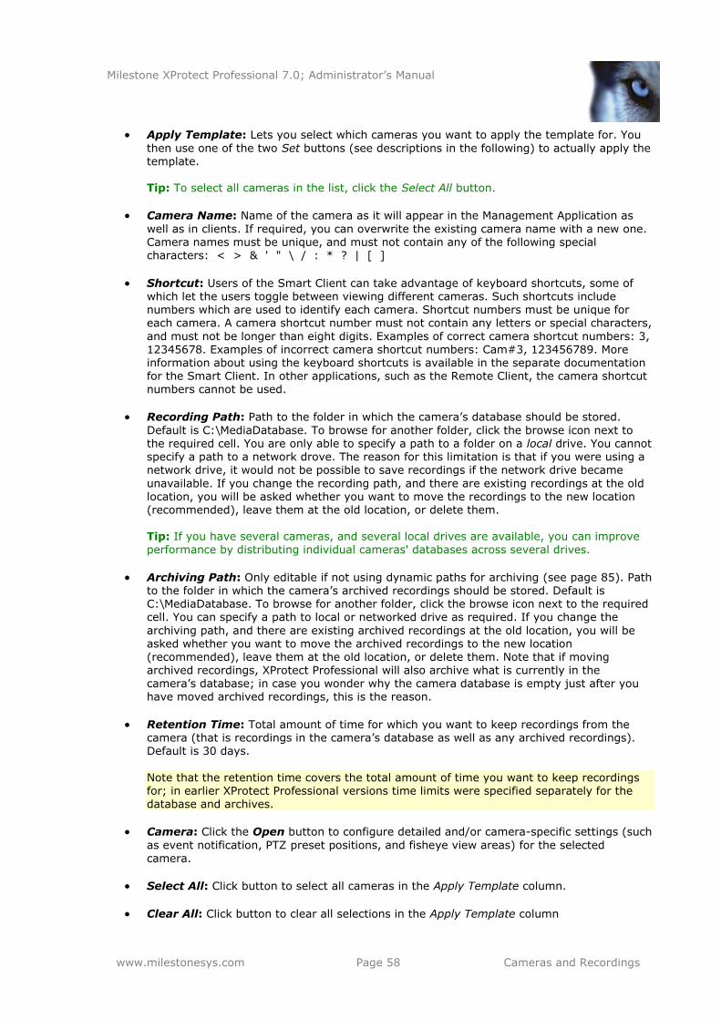
Milestone XProtect Professional 7.0; Administrator’s Manual
www.milestonesys.com Page 58 Cameras and Recordings
Apply Template: Lets you select which cameras you want to apply the template for. You
then use one of the two Set buttons (see descriptions in the following) to actually apply the template. Tip: To select all cameras in the list, click the Select All button.
Camera Name: Name of the camera as it will appear in the Management Application as
well as in clients. If required, you can overwrite the existing camera name with a new one. Camera names must be unique, and must not contain any of the following special characters: < > & ' " \ / : * ? | [ ]
Shortcut: Users of the Smart Client can take advantage of keyboard shortcuts, some of which let the users toggle between viewing different cameras. Such shortcuts include numbers which are used to identify each camera. Shortcut numbers must be unique for each camera. A camera shortcut number must not contain any letters or special characters,
and must not be longer than eight digits. Examples of correct camera shortcut numbers: 3, 12345678. Examples of incorrect camera shortcut numbers: Cam#3, 123456789. More information about using the keyboard shortcuts is available in the separate documentation for the Smart Client. In other applications, such as the Remote Client, the camera shortcut numbers cannot be used.
Recording Path: Path to the folder in which the camera’s database should be stored.
Default is C:\MediaDatabase. To browse for another folder, click the browse icon next to the required cell. You are only able to specify a path to a folder on a local drive. You cannot specify a path to a network drove. The reason for this limitation is that if you were using a
network drive, it would not be possible to save recordings if the network drive became
unavailable. If you change the recording path, and there are existing recordings at the old location, you will be asked whether you want to move the recordings to the new location (recommended), leave them at the old location, or delete them.
Tip: If you have several cameras, and several local drives are available, you can improve performance by distributing individual cameras' databases across several drives.
Archiving Path: Only editable if not using dynamic paths for archiving (see page 85). Path to the folder in which the camera’s archived recordings should be stored. Default is C:\MediaDatabase. To browse for another folder, click the browse icon next to the required cell. You can specify a path to local or networked drive as required. If you change the
archiving path, and there are existing archived recordings at the old location, you will be asked whether you want to move the archived recordings to the new location
(recommended), leave them at the old location, or delete them. Note that if moving archived recordings, XProtect Professional will also archive what is currently in the camera’s database; in case you wonder why the camera database is empty just after you have moved archived recordings, this is the reason.
Retention Time: Total amount of time for which you want to keep recordings from the camera (that is recordings in the camera’s database as well as any archived recordings). Default is 30 days.
Note that the retention time covers the total amount of time you want to keep recordings for; in earlier XProtect Professional versions time limits were specified separately for the database and archives.
Camera: Click the Open button to configure detailed and/or camera-specific settings (such
as event notification, PTZ preset positions, and fisheye view areas) for the selected camera.
Select All: Click button to select all cameras in the Apply Template column.
Clear All: Click button to clear all selections in the Apply Template column
Milestone XProtect Professional 7.0; Administrator’s Manual
www.milestonesys.com Page 59 Cameras and Recordings
Set selected template value on selected cameras: Lets you apply one or more
selected values from the template (rather than all values) to selected cameras.
Example: Only the selected values are applied using this method. To select more than one value press CTRL while selecting.
Set all template values on selected cameras: Lets you apply all values from the
template to selected cameras.
Dynamic Path Selection
When you configure video and recording, you can specify certain properties for many cameras in one go. In the case of Dynamic Path Selection, it is simply because the properties are shared by all cameras.
With dynamic paths for archiving (see page 85), you specify a number of different archiving paths, usually across several drives. If the path containing the XProtect Professional database on one of the drives you have selected for archiving, XProtect Professional will always try to archive to that drive first. If not, XProtect Professional automatically archives to the archiving drive with the most available space at any time, provided there is not a camera database using that drive. Which drive has the most available space may change during the archiving process, and archiving may therefore happen to several archiving drives during the same process. This fact will have no impact
on how users find and view archived recordings. Dynamic archiving paths are general for all your cameras; you cannot configure dynamic archiving paths for individual cameras. All properties on a white background are editable; properties on a light blue background cannot be
edited.
Enable dynamic path selection archives: Enables the use of dynamic path selection, allowing you to select which paths you want to use. The list of selectable paths initially
represents all drives on the server, both local and mapped drives. You can add further paths with the New path feature below the list.
Use: Lets you select particular paths for use as dynamic archiving paths. Also lets you
select a previously manually added path for removal (see description of Remove button in
the following)
Drive: Indicates which drive the path belongs on.
Path: Path to use as dynamic archiving path.
Drive Size: Total amount of space on the drive, that is free space as well as used space.
Free Space: Amount of free space available on the drive in question.
New path: Lets you specify a new path, and add it to the list using the Add button. Paths must be reachable by the surveillance system server, and you must specify the path using
the UNC (Universal Naming Convention) format, example: \\server\volume\directory\. When the new path is added, you can select it for use as a dynamic archiving path.
Add: Lets you add the path specified in the New path field to the list.
Milestone XProtect Professional 7.0; Administrator’s Manual
www.milestonesys.com Page 60 Cameras and Recordings
Remove: Lets you remove a selected path—which has previously been manually added—
from the list. You cannot remove any of the initially listed paths, not even when they are selected.
Video Recording
In XProtect Professional, the term recording means saving video and, if applicable, audio from a camera in the camera’s database on the surveillance system server. Video/audio is often saved only when there is a reason to do so, for example as long as motion is detected, when an event
occurs and until another event occurs, or within a certain period of time.
All properties on a white background are editable; properties on a light blue background cannot be edited. Note that all of the Video Recording properties can also be specified individually for each camera (see page 70).
Template: The template can help you configure similar properties quickly. Say you have
50 cameras and you want 10 seconds of pre-recording on all of them. Instead of having to enter the same piece of information 50 times, you can simply enter it once in the template, and then apply the template to the 50 cameras with only two clicks.
Apply Template: Lets you select which cameras you want to apply the template for. You then use one of the two Set buttons (see descriptions in the following) to actually apply the template.
Tip: To select all cameras in the list, click the Select All button.
Camera Name: Name of the camera as it will appear in the Management Application as well as in clients. If required, you can overwrite the existing camera name with a new one.
Camera names must be unique, and must not contain any of the following special characters: < > & ' " \ / : * ? | [ ]
Record on: Lets you select under which conditions video from the camera should be
recorded:
o Always: Record whenever the camera is enabled (see page 67) and scheduled to be online (see page 98). The latter allows for time-based recording).
o Never: Never record. Live video will be displayed, but—since no video is kept in
the database—users will not be able to play back video from the camera.
o Motion Detection: Select this to record video in which motion (see page 74) is
detected. Unless post-recording (see the following) is used, recording will stop immediately after the last motion is detected.
o Event: Select this to record video when an event occurs and until another event occurs. Use of recording on event requires that events (see page 107) have been
defined, and that you select start and stop events in the neighboring columns.
Tip: If you have not yet defined any suitable events, you can quickly do it: Use the Configure events list, located in the bottom left corner of the window.
o Motion Detection & Event: Select this to record video in which motion is
detected, or when an event occurs and until another event occurs. Remember to select start and stop events in the neighboring columns.
Start Event: Use when recording on Event or Motion Detection & Event. Select required
start event. Recording will begin when the start event occurs (or earlier if using pre-recording; see the following).
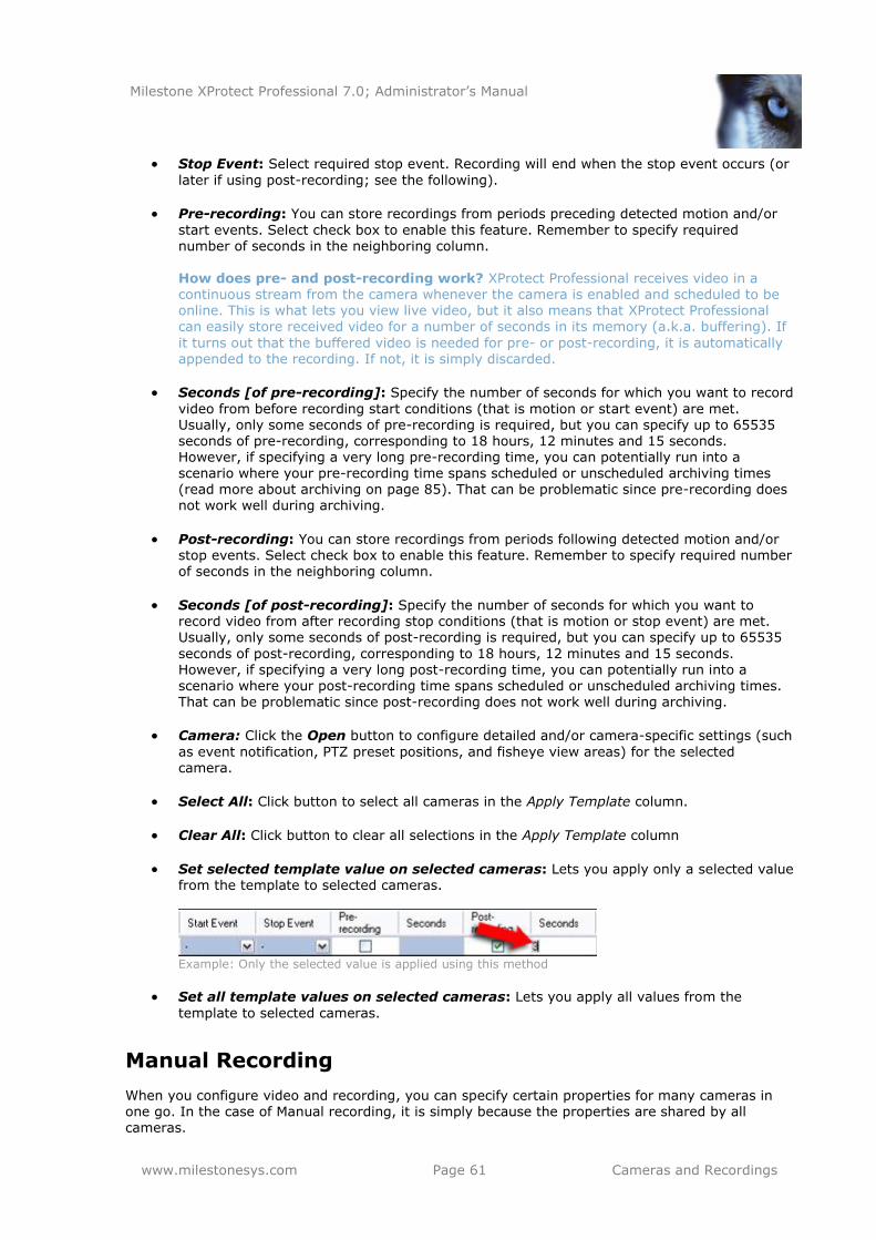
Milestone XProtect Professional 7.0; Administrator’s Manual
www.milestonesys.com Page 61 Cameras and Recordings
Stop Event: Select required stop event. Recording will end when the stop event occurs (or
later if using post-recording; see the following).
Pre-recording: You can store recordings from periods preceding detected motion and/or
start events. Select check box to enable this feature. Remember to specify required number of seconds in the neighboring column.
How does pre- and post-recording work? XProtect Professional receives video in a continuous stream from the camera whenever the camera is enabled and scheduled to be online. This is what lets you view live video, but it also means that XProtect Professional can easily store received video for a number of seconds in its memory (a.k.a. buffering). If
it turns out that the buffered video is needed for pre- or post-recording, it is automatically appended to the recording. If not, it is simply discarded.
Seconds [of pre-recording]: Specify the number of seconds for which you want to record
video from before recording start conditions (that is motion or start event) are met. Usually, only some seconds of pre-recording is required, but you can specify up to 65535 seconds of pre-recording, corresponding to 18 hours, 12 minutes and 15 seconds. However, if specifying a very long pre-recording time, you can potentially run into a scenario where your pre-recording time spans scheduled or unscheduled archiving times (read more about archiving on page 85). That can be problematic since pre-recording does not work well during archiving.
Post-recording: You can store recordings from periods following detected motion and/or stop events. Select check box to enable this feature. Remember to specify required number
of seconds in the neighboring column.
Seconds [of post-recording]: Specify the number of seconds for which you want to record video from after recording stop conditions (that is motion or stop event) are met. Usually, only some seconds of post-recording is required, but you can specify up to 65535
seconds of post-recording, corresponding to 18 hours, 12 minutes and 15 seconds. However, if specifying a very long post-recording time, you can potentially run into a scenario where your post-recording time spans scheduled or unscheduled archiving times. That can be problematic since post-recording does not work well during archiving.
Camera: Click the Open button to configure detailed and/or camera-specific settings (such
as event notification, PTZ preset positions, and fisheye view areas) for the selected camera.
Select All: Click button to select all cameras in the Apply Template column.
Clear All: Click button to clear all selections in the Apply Template column
Set selected template value on selected cameras: Lets you apply only a selected value from the template to selected cameras.
Example: Only the selected value is applied using this method
Set all template values on selected cameras: Lets you apply all values from the
template to selected cameras.
Manual Recording
When you configure video and recording, you can specify certain properties for many cameras in one go. In the case of Manual recording, it is simply because the properties are shared by all cameras.
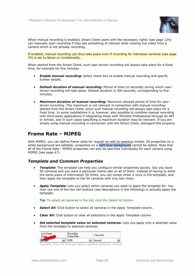
Milestone XProtect Professional 7.0; Administrator’s Manual
www.milestonesys.com Page 62 Cameras and Recordings
When manual recording is enabled, Smart Client users with the necessary rights (see page 124) can manually start recording if they see something of interest while viewing live video from a
camera which is not already recording. If enabled, manual recording can thus take place even if recording for individual cameras (see page 70) is set to Never or Conditionally. When started from the Smart Client, such user-driven recording will always take place for a fixed
time, for example for five minutes.
Enable manual recording: Select check box to enable manual recording and specify further details.
Default duration of manual recording: Period of time (in seconds) during which user-driven recording will take place. Default duration is 300 seconds, corresponding to five minutes.
Maximum duration of manual recording: Maximum allowed period of time for user-driven recording. This maximum is not relevant in connection with manual recording started from the Smart Client, since such manual recording will always take place for a fixed time. In some installations it is, however, also possible to combine manual recording
with third-party applications if integrating these with XProtect Professional through an API or similar, and in such cases specifying a maximum duration may be relevant. If you are simply using manual recording in connection with the Smart Client, disregard this property.
Frame Rate – MJPEG
With MJPEG, you can define frame rates for regular as well as speedup modes. All properties on a white background are editable; properties on a light blue background cannot be edited. Note that all of the Frame Rate - MJPEG properties can also be specified individually for each camera using
MJPEG (see page 67).
Template and Common Properties
Template: The template can help you configure similar properties quickly. Say you have 50 cameras and you want a particular frame rate on all of them. Instead of having to enter
the same piece of information 50 times, you can simply enter it once in the template, and then apply the template to the 50 cameras with only two clicks.
Apply Template: Lets you select which cameras you want to apply the template for. You
then use one of the two Set buttons (see descriptions in the following) to actually apply the template. Tip: To select all cameras in the list, click the Select All button.
Select All: Click button to select all cameras in the Apply Template column.
Clear All: Click button to clear all selections in the Apply Template column
Set selected template value on selected cameras: Lets you apply only a selected value
from the template to selected cameras.
Example: Only the selected value is applied using this method
Milestone XProtect Professional 7.0; Administrator’s Manual
www.milestonesys.com Page 63 Cameras and Recordings
Set all template values on selected cameras: Lets you apply all values from the
template to selected cameras.
Camera Name: Name of the camera as it will appear in the Management Application as
well as in clients. If required, you can overwrite the existing camera name with a new one. Camera names must be unique, and must not contain any of the following special characters: < > & ' " \ / : * ? | [ ]
Regular Frame Rate Properties
Live frame rate: Required average frame rate for live video from the camera. Select
number of frames, then select required interval (per second, minute or hour) in the Frame Rate Time Base column.
Recording frame rate: Required average frame rate for recorded video from the camera.
Select number of frames, then select required interval (per second, minute or hour) in the Frame Rate Time Base column.
Frame Rate Time Base: Select required unit for live and recording frame rates (per
second, minute, or hour).
Camera: Click the Open button to configure detailed and/or camera-specific settings (such as event notification, PTZ preset positions, and fisheye view areas) for the selected
camera.
Speedup Frame Rate Properties
Enable Speedup: The speedup feature lets you use a higher than normal frame rate if
motion is detected and/or an event occurs. When you enable speedup, further columns for specifying speedup details become available.
Live Frame Rate: Required average speedup frame rate for viewing live video from the camera. Select number of frames, then select required interval (per second, minute or
hour) in the Frame Rate Time Base column. The frame rate must be higher than the live frame rate specified under normal mode.
Recording frame rate: Required average speedup frame rate for viewing recorded video
from the camera. Select number of frames, then select required interval (per second,
minute or hour) in the Frame Rate Time Base column. The frame rate must be higher than the recording frame rate specified under normal mode.
Frame Rate Time Base: Select required unit for live and recording speedup frame rates
(per second, minute, or hour). Note that you can only select time bases that let you speed up frame rates. Example: If you have specified 15 frames per second in normal mode, you cannot specify 16 frames per minute or hour in speedup mode.
Speedup on: Lets you select under which conditions to use speedup frame rates:
o Motion Detection: Select this to speed up when motion (see page 74) is detected.
Normal frame rates will be resumed immediately after the last motion is detected.
o Event: Select this to speed up when an event occurs and until another event
occurs. Use of speedup on event requires that events (see page 107) have been defined, and that you select start and stop events in the neighboring columns. Tip: If you have not yet defined any suitable events, you can quickly do it: Use the Configure events list, located in the bottom left corner of the window.
o Motion Detection & Event: Select this to speed up when motion is detected, or
when an event occurs and until another event occurs. Remember to select start
Milestone XProtect Professional 7.0; Administrator’s Manual
www.milestonesys.com Page 64 Cameras and Recordings
and stop events in the neighboring columns.
o Schedule only: Select this to speed up according to the camera’s speedup
schedule (see page 99) only.
Start Event: Select required start event. The camera will begin using the speedup frame rates when the start event occurs.
Stop Event: Select required start event. The camera will return to the normal frame rates when the stop event occurs.
Camera: Click the Open button to configure detailed and/or camera-specific settings (such as event notification, PTZ preset positions, and fisheye view areas) for the selected camera.
Frame Rate – MPEG
All properties on a white background are editable; properties on a light blue background cannot be edited. Note that the Frame Rate - MPEG properties can also be specified individually for each camera using MPEG (see page 67).
Template: The template can help you configure similar properties quickly. Say you have
50 cameras and you want a particular frame rate on all of them. Instead of having to enter
the same piece of information 50 times, you can simply enter it once in the template, and then apply the template to the 50 cameras with only two clicks.
Apply Template: Lets you select which cameras you want to apply the template for. You
then use one of the two Set buttons (see descriptions in the following) to actually apply the template. Tip: To select all cameras in the list, click the Select All button.
Camera Name: Name of the camera as it will appear in the Management Application as well as in clients. If required, you can overwrite the existing camera name with a new one. Camera names must be unique, and must not contain any of the following special characters: < > & ' " \ / : * ? | [ ]
Live FPS: Lets you select the camera’s live frame rate per second (FPS).
Record Keyframe Only: Keyframes stored at specified intervals record the entire view of
the camera, whereas the following frames record only pixels that change; this helps greatly reduce the size of MPEG files. Select the check box if you only want to record keyframes. Note that you can specify exceptions in the neighboring column.
Record All Frames on: Allows you to make exceptions if you have selected Record
Keyframes Only:
o Motion Detection: Select this to record all frames when motion 74 is detected. Two seconds after the last motion is detected, the camera will return to recording
keyframes only.
o Event: Select this to record all frames when an event occurs and until another event occurs. Requires that events (see page 107) have been defined, and that you select start and stop events in the neighboring columns.
Tip: If you have not yet defined any suitable events, you can quickly do it: Use the
Configure events list, located in the bottom left corner of the window.
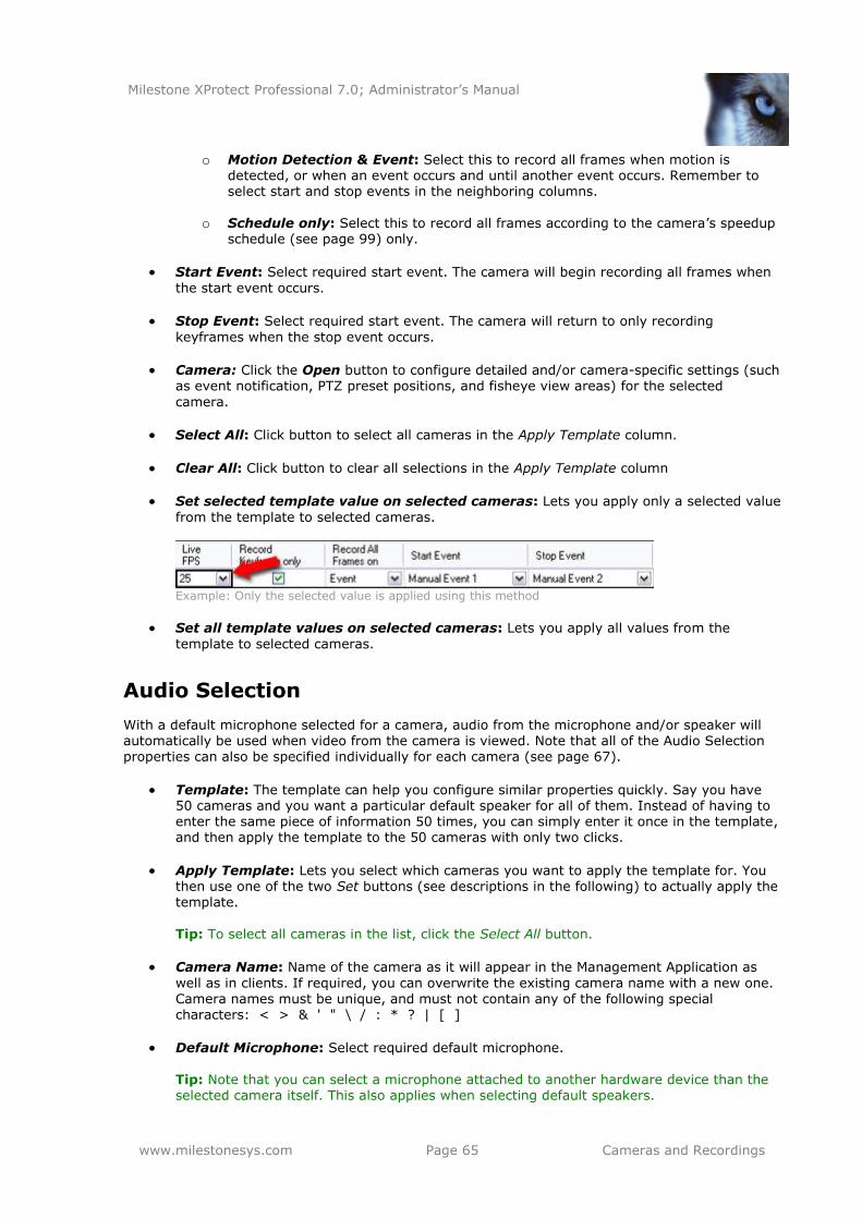
Milestone XProtect Professional 7.0; Administrator’s Manual
www.milestonesys.com Page 65 Cameras and Recordings
o Motion Detection & Event: Select this to record all frames when motion is detected, or when an event occurs and until another event occurs. Remember to select start and stop events in the neighboring columns.
o Schedule only: Select this to record all frames according to the camera’s speedup
schedule (see page 99) only.
Start Event: Select required start event. The camera will begin recording all frames when
the start event occurs.
Stop Event: Select required start event. The camera will return to only recording
keyframes when the stop event occurs.
Camera: Click the Open button to configure detailed and/or camera-specific settings (such as event notification, PTZ preset positions, and fisheye view areas) for the selected
camera.
Select All: Click button to select all cameras in the Apply Template column.
Clear All: Click button to clear all selections in the Apply Template column
Set selected template value on selected cameras: Lets you apply only a selected value
from the template to selected cameras.
Example: Only the selected value is applied using this method
Set all template values on selected cameras: Lets you apply all values from the
template to selected cameras.
Audio Selection
With a default microphone selected for a camera, audio from the microphone and/or speaker will automatically be used when video from the camera is viewed. Note that all of the Audio Selection properties can also be specified individually for each camera (see page 67).
Template: The template can help you configure similar properties quickly. Say you have 50 cameras and you want a particular default speaker for all of them. Instead of having to enter the same piece of information 50 times, you can simply enter it once in the template, and then apply the template to the 50 cameras with only two clicks.
Apply Template: Lets you select which cameras you want to apply the template for. You then use one of the two Set buttons (see descriptions in the following) to actually apply the template.
Tip: To select all cameras in the list, click the Select All button.
Camera Name: Name of the camera as it will appear in the Management Application as
well as in clients. If required, you can overwrite the existing camera name with a new one.
Camera names must be unique, and must not contain any of the following special characters: < > & ' " \ / : * ? | [ ]
Default Microphone: Select required default microphone.
Tip: Note that you can select a microphone attached to another hardware device than the selected camera itself. This also applies when selecting default speakers.
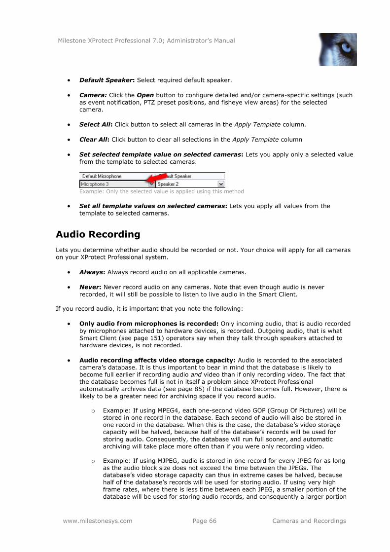
Milestone XProtect Professional 7.0; Administrator’s Manual
www.milestonesys.com Page 66 Cameras and Recordings
Default Speaker: Select required default speaker.
Camera: Click the Open button to configure detailed and/or camera-specific settings (such
as event notification, PTZ preset positions, and fisheye view areas) for the selected camera.
Select All: Click button to select all cameras in the Apply Template column.
Clear All: Click button to clear all selections in the Apply Template column
Set selected template value on selected cameras: Lets you apply only a selected value
from the template to selected cameras.
Example: Only the selected value is applied using this method
Set all template values on selected cameras: Lets you apply all values from the
template to selected cameras.
Audio Recording
Lets you determine whether audio should be recorded or not. Your choice will apply for all cameras on your XProtect Professional system.
Always: Always record audio on all applicable cameras.
Never: Never record audio on any cameras. Note that even though audio is never
recorded, it will still be possible to listen to live audio in the Smart Client. If you record audio, it is important that you note the following:
Only audio from microphones is recorded: Only incoming audio, that is audio recorded
by microphones attached to hardware devices, is recorded. Outgoing audio, that is what Smart Client (see page 151) operators say when they talk through speakers attached to hardware devices, is not recorded.
Audio recording affects video storage capacity: Audio is recorded to the associated camera’s database. It is thus important to bear in mind that the database is likely to become full earlier if recording audio and video than if only recording video. The fact that the database becomes full is not in itself a problem since XProtect Professional automatically archives data (see page 85) if the database becomes full. However, there is
likely to be a greater need for archiving space if you record audio.
o Example: If using MPEG4, each one-second video GOP (Group Of Pictures) will be stored in one record in the database. Each second of audio will also be stored in one record in the database. When this is the case, the database’s video storage capacity will be halved, because half of the database’s records will be used for
storing audio. Consequently, the database will run full sooner, and automatic archiving will take place more often than if you were only recording video.
o Example: If using MJPEG, audio is stored in one record for every JPEG for as long
as the audio block size does not exceed the time between the JPEGs. The database’s video storage capacity can thus in extreme cases be halved, because half of the database’s records will be used for storing audio. If using very high
frame rates, where there is less time between each JPEG, a smaller portion of the database will be used for storing audio records, and consequently a larger portion
Milestone XProtect Professional 7.0; Administrator’s Manual
www.milestonesys.com Page 67 Cameras and Recordings
will be available for storing video. Anyway, the database will run full sooner, and automatic archiving will take place more often than if you were only recording video.
Above examples are simplified, the exact available video storage capacity will also depend on GOP/JPEG and audio kilobyte size.
Storage Information
Lets you view how much storage space you have on your XProtect Professional system—and not
least how much of it is free:
Drive: Letter representing the drive in question, for example C:.
Path: Path to the storage area, for example C:\ or \\OurServer\OurFolder\OurSubfolder\.
Usage: What the storage area is used for, for example recording or archiving.
Drive Size: Total size of the drive.
Video Data: Amount of video data on the drive.
Other Data: Amount of other data on the drive.
Free Space: Amount of unused space left on the drive. Tip: To quickly view disk space usage in a pie chart format, select the line representing the drive
you are interested in.
Camera-specific Configuration
To specify video, recording and camera-specific settings (such as event notification, PTZ preset positions, and fisheye view areas) for each individual camera.
1. In the Management Application’s navigation pane, expand Advanced Configuration, and
expand Cameras and Storage Information.
2. Right-click the required camera, and select Properties.
3. Specify properties as required for Camera, Frame Rate, Video, Audio, Recording, Recording & Archiving Paths, Event Notification, Output, Motion Detection & Exclude Regions, and—if applicable—Fisheye, PTZ Preset Positions, PTZ Patrolling, and PTZ on Event. All of the
properties are described on the following pages.
4. Save your configuration changes by clicking the Save Configuration button in the Management Application’s toolbar.
Camera
Enabled: Cameras are by default enabled, meaning that provided they are scheduled to be
online (see page 98), they are able to transfer video to XProtect Professional. If required, you can disable an individual camera, in which case no video/audio will be transferred from the camera source to XProtect Professional.
Milestone XProtect Professional 7.0; Administrator’s Manual
www.milestonesys.com Page 68 Cameras and Recordings
Camera name: Name of the camera as it will appear in the Management Application as
well as in clients. If required, you can overwrite the existing camera name with a new one. Camera names must be unique, and must not contain any of the following special characters: < > & ' " \ / : * ? | [ ]
Tip: Camera names can be very long if required: the upper limit is more than 2000 characters, although such long camera names are hardly ever needed.
Camera shortcut number: Users of the Smart Client can take advantage of keyboard shortcuts, some of which let the users toggle between viewing different cameras. Such shortcuts include numbers which are used to identify each camera.
Shortcut numbers must be unique for each camera. A camera shortcut number must not contain any letters or special characters, and must not be longer than eight digits. Examples of correct camera shortcut numbers: 3, 12345678. Examples of incorrect camera shortcut numbers: Cam#3, 123456789. More information about using the keyboard shortcuts is available in the separate
documentation for the Smart Client. In other applications, such as the Remote Client, the camera shortcut numbers cannot be used.
Frame Rate
If the Camera Uses the MJPEG Video Format
With MJPEG, you can define frame rates for regular as well as speedup modes: Regular Frame Rate Mode:
Live frame rate: Frame rate for viewing live video from the camera. Select number of frames in the first field, and required interval (per second, minute or hour) in the second field.
Recording frame rate: Frame rate for viewing recorded video from the camera. Select
number of frames in the first field, and required interval (per second, minute or hour) in the second field.
Speedup Frame Rate Mode:
Enable speedup frame rate: The speedup feature lets you use a higher than normal frame rate if motion is detected and/or an event occurs. When you enable speedup, further fields for specifying speedup details become available.
Live frame rate: Speedup frame rate for viewing live video from the camera. Select number of frames in the first field, and required interval (per second, minute or hour) in the second field. The frame rate must be higher than the live frame rate specified under
normal mode.
Recording frame rate: Speedup frame rate for viewing recorded video from the camera. Select number of frames in the first field, and required interval (per second, minute or
hour) in the second field. The frame rate must be higher than the recording frame rate
specified under normal mode.
On motion: Select this check box to use the speedup frame rates when motion is
detected. The camera will return to the normal frame rates two seconds after the last motion is detected.

Milestone XProtect Professional 7.0; Administrator’s Manual
www.milestonesys.com Page 69 Cameras and Recordings
On event: Select this check box to use the speedup frame rates when an event occurs and
until another event occurs. Use of speedup on event requires that events (see page 107) have been defined, and that you select start and stop events in the neighboring lists.
Tip: If you have not yet defined any suitable events, you can quickly do it: Use the Configure events list, located below the other fields.
Start event: Select required start event. The camera will begin using the speedup frame rates when the start event occurs.
Stop event: Select required start event. The camera will return to the normal frame rates
when the stop event occurs. Tip: Speedup does not necessarily have to be based on motion- or events; you can also use scheduling to configure speedup based on particular periods of time (see page 99). If you prefer
such time-based speedup, you should still enable the use of speedup by selecting the Enable speedup check box.
If the Camera Uses the MPEG Video Format
With MPEG, you can define frame rate as well as when to record keyframes or all frames:
Frame rate per second: Frame rate for viewing live and recorded video from the camera.
Select number of frames per second.
Record keyframes only: Keyframes stored at specified intervals record the entire view of
the camera, whereas the following frames record only pixels that change; this helps greatly reduce the size of MPEG files. Select the check box if you only want to record keyframes. Note that you can specify exceptions if motion is detected or events occur (see the following).
Record all frames on motion: Allows you to make exceptions if you have selected record
keyframes only. Select this check box to record all frames when motion is detected. Two seconds after the last motion is detected, the camera will return to recording keyframes only.
Record all frames on event: Allows you to make exceptions if you have selected record keyframes only. Select this check box to record all frames when an event occurs and until
another event occurs. Use of this feature requires that events (see page 107) have been defined, and that you select start and stop events in the neighboring lists.
Tip: If you have not yet defined any suitable events, you can quickly do it: Use the Configure events list, located below the other fields.
Start event: Select required start event. The camera will begin recording all fames when
the start event occurs.
Stop event: Select required start event. When the stop event occurs, the camera will
return to recording keyframes only.
Video
When you configure specific cameras, properties are to a large extent camera-specific. Since such properties vary from camera to camera, descriptions in the following are for guidance only. If the selected camera is accessible, a live preview is displayed. Click the Configure Video Properties button to open a separate window with properties for the selected camera.
Milestone XProtect Professional 7.0; Administrator’s Manual
www.milestonesys.com Page 70 Cameras and Recordings
The video properties typically let you control bandwidth, brightness, compression, contrast, resolution, rotation, etc. by overwriting existing values of selecting new ones.
When adjusting video settings, you are—for most cameras—able to preview the effect of your settings in an image below the fields. Video settings may feature an Include Date and Time setting. If set to Yes, date and time from the camera will be included in video. Note, however, that cameras are separate units which may have separate timing devices, power supplies, etc. Camera time and XProtect Professional system time
may therefore not correspond fully, and this may occasionally lead to confusion. As all frames are time-stamped by XProtect Professional upon reception, and exact date and time information for
each image is thus already known, it is recommended that the setting is set to No. Tip: For consistent time synchronization, you may—if supported by the camera—automatically synchronize camera and system time through a time server.
Audio
Lets you select a default microphone and/or speaker for the camera. With a default microphone and/or a speaker selected for a camera, audio from the microphone and/or a speaker will automatically be used when video from the camera is viewed. If a microphone and/or a speaker is attached to the same hardware device as the camera, that microphone/speaker will be the camera’s default microphone/speaker if you do not select
otherwise.
Tip: Note that you can select a microphone and/or a speaker attached to another hardware device than the selected camera itself.
Default microphone: Select required microphone.
Default speaker: Select required speaker.
The ability to select a default microphone and/or a speaker for the camera requires that at least one microphone and/or speaker has been attached to a hardware device on the surveillance system.
Recording Settings
In XProtect Professional, the term recording means saving video and, if applicable, audio from a camera in the camera’s database on the surveillance system server. Video/audio is often saved only when there is a reason to do so, for example as long as motion is detected, when an event
occurs and until another event occurs, or within a certain period of time. When you configure specific cameras, recording properties include:
Always: Record whenever the camera is enabled (see page 67) and scheduled to be
online. The latter allows for time-based recording; see also page 98.
Never: Never record. Live video will be displayed, but—since no video is kept in the database—users will not be able to play back video from the camera.
Conditionally: Record when certain conditions are met. When you select this option, specify required conditions (see the following).
On built-in motion detection: Select this check box to record video in which motion (see
page 74) is detected. Unless post-recording (see the following) is used, recording will stop immediately after the last motion is detected.
Milestone XProtect Professional 7.0; Administrator’s Manual
www.milestonesys.com Page 71 Cameras and Recordings
On event: Select this check box to record video when an event occurs and until another
event occurs. Use of recording on event requires that events (see page 107) have been defined, and that you select start and stop events in the neighboring lists.
Tip: If you have not yet defined any suitable events, you can quickly do it: Use the Configure events list, located below the other fields.
Start event: Select required start event. Recording will begin when the start event occurs (or earlier if using pre-recording; see the following).
Stop event: Select required start event. Recording will end when the stop event occurs (or
later if using post-recording; see the following). When the option Conditionally is selected, you can store recordings from periods preceding and following detected motion and/or specified events. Example: If you have defined that video should
be stored when a door is opened, being able to see what happened immediately prior to the door being opened may also be important. Say you have specified that video should be stored conditionally on event, with a start event called Door Opened and a stop event called Door Closed. With three seconds of pre-recording, video will be recorded from three seconds before Door Opened occurs and until Door Closed occurs.
Enable pre-recording: Available only when the option Conditional is selected. Specify the
number of seconds for which you want to record video from before recording start conditions (that is motion or start event) are met.
Enable post-recording: Available only when the option Conditional is selected. Specify
the number of seconds for which you want to record video after recording stop conditions (that is motion end or stop event) are met.
How does pre- and post-recording work? XProtect Professional receives video in a continuous
stream from the camera whenever the camera is enabled and scheduled to be online. This is what lets you view live video, but it also means that XProtect Professional can easily store received video for a number of seconds in its memory (a.k.a. buffering). If it turns out that the buffered video is needed for pre- or post-recording, it is automatically appended to the recording. If not, it is simply discarded. Note that manual recording (see page 61) may be enabled. With manual recording, Smart Client
users with the necessary rights (see page 124) can manually start recording if they see something of interest while viewing live video from a camera which is not already recording. If enabled,
manual recording can thus take place even if recording for individual cameras is set to Never or Conditionally.
Recording & Archiving Paths
Recording path: Path to the folder in which the camera’s database should be stored.
Default is C:\MediaDatabase. To browse for another folder, click the browse button next to the Recording path field. You are only able to specify a path to a folder on a local drive. If using a network drive, it would not be possible to save recordings if the network drive became unavailable.
If you change the recording path, and there are existing recordings at the old location, you will be asked whether you want to move the recordings to the new location
(recommended), leave them at the old location, or delete them.
Tip: If you have several cameras, and several local drives are available, you can improve performance by distributing individual cameras' databases across several drives.
Delete Database: Click button to delete all recordings in the database for the camera. Archived recordings will not be affected.
Milestone XProtect Professional 7.0; Administrator’s Manual
www.milestonesys.com Page 72 Cameras and Recordings
IMPORTANT: Use with caution; all recordings in the database for the camera will be permanently deleted. As a security measure, you will be asked to confirm the deletion.
Archiving path: Only available if not using dynamic paths for archiving. Path to the folder in which the camera’s archived recordings should be stored. Default is C:\MediaDatabase\Archives. To browse for another folder, click the browse button next to
the Archiving path field. You can specify a path to local or networked drive as required. If you change the archiving path, and there are existing archived recordings at the old location, you will be asked whether you want to move the archived recordings to the new location (recommended), leave them at the old location, or delete them. Note that if
moving archived recordings, XProtect Professional will also archive what is currently in the camera’s database; in case you wonder why the camera database is empty just after you have moved archived recordings, this is the reason.
Delete Archives: Click button to delete all archived recordings for the camera. Recordings in the camera’s regular database will not be affected. The ability to delete is available regardless of whether you use a single archiving path or dynamic archiving paths.
IMPORTANT: Use with caution; all archived recordings for the camera will be permanently deleted. As a security measure, you will be asked to confirm the deletion.
Retention time: Total amount of time for which you want to keep recordings from the
camera (that is recordings in the camera’s database as well as any archived recordings). Default is 30 days.
Note that the retention time covers the total amount of time you want to keep recordings for; in earlier XProtect Professional versions time limits were specified separately for the database and archives.
Database repair action: Select which action to take if the database becomes corrupted:
o Repair, scan, delete if fails: Default action. If the database becomes corrupted, two
different repair methods will be attempted: a fast repair and a thorough repair. If both repair methods fail, the contents of the database will be deleted.
o Repair, delete if fails: If the database becomes corrupted, a fast repair will be attempted. If the fast repair fails, the contents of the database will be deleted.
o Repair, archive if fails: If the database becomes corrupted, a fast repair will be attempted. If the fast repair fails, the contents of the database will be archived.
o Delete (no repair): If the database becomes corrupted, the contents of the database will be deleted.
o Archive (no repair): If the database becomes corrupted, the contents of the
database will be archived.
No video can be recorded in a database while it is being repaired. For large installations, a repair may take several hours, especially if the Repair, scan, delete if fails action (which involves two different repair methods) is selected, and the first repair method (fast repair) fails.
Why archive a corrupt database? Provided the corrupt database has been archived, it can often be repaired by the Viewer (see page 168): Open the Viewer and attempt to browse the archived recordings from the camera in question. Browsing will initially fail, but this will make the Viewer start repairing the corrupt database. Tip: There are several things you can do to prevent that your databases become corrupt in
the first place. See Protect Recording Databases from Corruption on page 148.
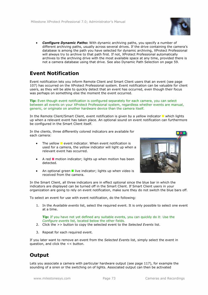
Milestone XProtect Professional 7.0; Administrator’s Manual
www.milestonesys.com Page 73 Cameras and Recordings
Configure Dynamic Paths: With dynamic archiving paths, you specify a number of
different archiving paths, usually across several drives. If the drive containing the camera’s database is among the path you have selected for dynamic archiving, XProtect Professional will always try to archive to that path first. If not, XProtect Professional automatically archives to the archiving drive with the most available space at any time, provided there is not a camera database using that drive. See also Dynamic Path Selection on page 59.
Event Notification
Event notification lets you inform Remote Client and Smart Client users that an event (see page 107) has occurred on the XProtect Professional system. Event notification can be valuable for client users, as they will be able to quickly detect that an event has occurred, even though their focus was perhaps on something else the moment the event occurred. Tip: Even though event notification is configured separately for each camera, you can select
between all events on your XProtect Professional system, regardless whether events are manual, generic, or originate on another hardware device than the camera itself. In the Remote Client/Smart Client, event notification is given by a yellow indicator which lights up when a relevant event has taken place. An optional sound on event notification can furthermore be configured in the Smart Client itself.
In the clients, three differently colored indicators are available for
each camera:
The yellow event indicator. When event notification is
used for a camera, the yellow indicator will light up when a relevant event has occurred.
A red motion indicator; lights up when motion has been
detected.
An optional green live indicator; lights up when video is received from the camera.
In the Smart Client, all three indicators are in effect optional since the blue bar in which the indicators are displayed can be turned off in the Smart Client. If Smart Client users in your
organization are going to rely on event notification, make sure they do not switch the blue bars off. To select an event for use with event notification, do the following:
1. In the Available events list, select the required event. It is only possible to select one event at a time.
Tip: If you have not yet defined any suitable events, you can quickly do it: Use the Configure events list, located below the other fields.
2. Click the >> button to copy the selected event to the Selected Events list.
3. Repeat for each required event.
If you later want to remove an event from the Selected Events list, simply select the event in
question, and click the << button.
Output
Lets you associate a camera with particular hardware output (see page 117), for example the
sounding of a siren or the switching on of lights. Associated output can then be activated
Milestone XProtect Professional 7.0; Administrator’s Manual
www.milestonesys.com Page 74 Cameras and Recordings
automatically when motion is detected in video from the camera, or manually when Smart Client or Remote Client users with the necessary rights (see page 124) view live video from the camera.
1. In the Available output list, select the required output. It is only possible to select one output at a time.
Tip: If you have not yet defined any suitable output, you can quickly do it: Use the Configure Output button, located below the other fields.
Tip: Even though output is configured separately for each camera, you can select between all output on your XProtect Professional system, regardless whether output originates on
another hardware device than the camera itself.
2. Click the >> button to copy the selected output to:
the On manual activation list, in which case the output will be available for manual
activation in the Smart Client and Remote Client.
- and/or -
the On motion detected list, in which case the output will be activated when motion is detected in video from the camera.
If required, the same output can appear on both lists.
3. Repeat for each required output. If you later want to remove an output from the one of the lists, simply select the output in question, and click the << button.
Motion Detection & Exclude Regions
When you configure specific cameras, adjusting motion detection is important since it may
determine when video from the camera is recorded, when e-mail notifications are generated, when hardware output (such as lights or sirens) is activated, etc. Time spent on finding the best possible motion detection settings for each camera may help you later avoid unnecessary recordings, notifications, etc. Depending on the physical location of the camera, it may be a very good idea to test motion detection under different physical conditions (day/night, windy/calm weather, etc.).
Cameras that do not support multiple simultaneous video streams will not be able to connect to the
surveillance server and the Management Application at the same time; therefore it is recommended to stop the Recording Server service (see page 119) when configuring such devices for motion detection and PTZ. See also page 83. Before you configure motion detection for a camera, it is highly recommended that you have configured the camera’s video properties, such as compression, resolution, etc. (see page 69). When ready, do the following:
1. Ask yourself whether there are any areas which should be excluded from motion detection (for example if the camera covers an area where a tree is swaying in the wind or where cars regularly pass by in the background). If so, you can avoid detection of irrelevant motion by following the points below. If not, continue to step 2.
In the Exclude regions section in lower part of the window, select Enable. The
preview image is now divided into small sections by a grid. To define areas which should be excluded from motion detection, drag the mouse pointer over the required areas in the preview image while pressing the mouse button down. Left mouse button selects a grid section; right mouse button clears a grid section.
Selected areas are highlighted in blue. Occasionally, you may also want to take
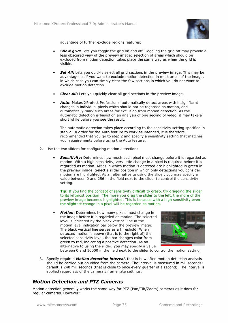
Milestone XProtect Professional 7.0; Administrator’s Manual
www.milestonesys.com Page 75 Cameras and Recordings
advantage of further exclude regions features:
Show grid: Lets you toggle the grid on and off. Toggling the grid off may provide a
less obscured view of the preview image; selection of areas which should be excluded from motion detection takes place the same way as when the grid is visible.
Set All: Lets you quickly select all grid sections in the preview image. This may be advantageous if you want to exclude motion detection in most areas of the image, in which case you can simply clear the few sections in which you do not want to exclude motion detection.
Clear All: Lets you quickly clear all grid sections in the preview image.
Auto: Makes XProtect Professional automatically detect areas with insignificant
changes in individual pixels which should not be regarded as motion, and automatically mark such areas for exclusion from motion detection. As the automatic detection is based on an analysis of one second of video, it may take a short while before you see the result.
The automatic detection takes place according to the sensitivity setting specified in step 2. In order for the Auto feature to work as intended, it is therefore recommended that you go to step 2 and specify a sensitivity setting that matches your requirements before using the Auto feature.
2. Use the two sliders for configuring motion detection:
Sensitivity: Determines how much each pixel must change before it is regarded as motion. With a high sensitivity, very little change in a pixel is required before it is regarded as motion. Areas in which motion is detected are highlighted in green in
the preview image. Select a slider position in which only detections you consider motion are highlighted. As an alternative to using the slider, you may specify a value between 0 and 256 in the field next to the slider to control the sensitivity setting.
Tip: If you find the concept of sensitivity difficult to grasp, try dragging the slider to its leftmost position: The more you drag the slider to the left, the more of the
preview image becomes highlighted. This is because with a high sensitivity even the slightest change in a pixel will be regarded as motion.
Motion: Determines how many pixels must change in
the image before it is regarded as motion. The selected level is indicated by the black vertical line in the motion level indication bar below the preview image. The black vertical line serves as a threshold: When detected motion is above (that is to the right of) the selected sensitivity level, the bar changes color from green to red, indicating a positive detection. As an
alternative to using the slider, you may specify a value between 0 and 10000 in the field next to the slider to control the motion setting.
3. Specify required Motion detection interval, that is how often motion detection analysis
should be carried out on video from the camera. The interval is measured in milliseconds;
default is 240 milliseconds (that is close to once every quarter of a second). The interval is
applied regardless of the camera’s frame rate settings.
Motion Detection and PTZ Cameras
Motion detection generally works the same way for PTZ (Pan/Tilt/Zoom) cameras as it does for regular cameras. However:
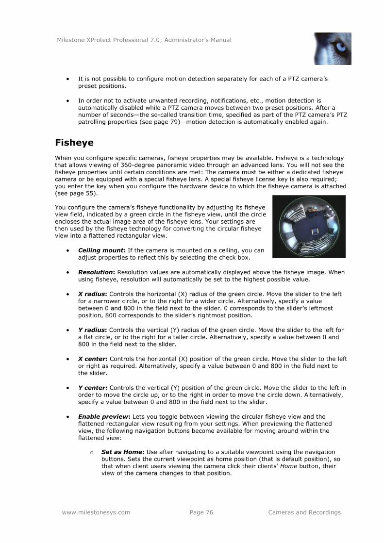
Milestone XProtect Professional 7.0; Administrator’s Manual
www.milestonesys.com Page 76 Cameras and Recordings
It is not possible to configure motion detection separately for each of a PTZ camera’s
preset positions.
In order not to activate unwanted recording, notifications, etc., motion detection is
automatically disabled while a PTZ camera moves between two preset positions. After a number of seconds—the so-called transition time, specified as part of the PTZ camera’s PTZ patrolling properties (see page 79)—motion detection is automatically enabled again.
Fisheye
When you configure specific cameras, fisheye properties may be available. Fisheye is a technology that allows viewing of 360-degree panoramic video through an advanced lens. You will not see the
fisheye properties until certain conditions are met: The camera must be either a dedicated fisheye camera or be equipped with a special fisheye lens. A special fisheye license key is also required; you enter the key when you configure the hardware device to which the fisheye camera is attached (see page 55). You configure the camera’s fisheye functionality by adjusting its fisheye view field, indicated by a green circle in the fisheye view, until the circle
encloses the actual image area of the fisheye lens. Your settings are then used by the fisheye technology for converting the circular fisheye view into a flattened rectangular view.
Ceiling mount: If the camera is mounted on a ceiling, you can
adjust properties to reflect this by selecting the check box.
Resolution: Resolution values are automatically displayed above the fisheye image. When
using fisheye, resolution will automatically be set to the highest possible value.
X radius: Controls the horizontal (X) radius of the green circle. Move the slider to the left for a narrower circle, or to the right for a wider circle. Alternatively, specify a value
between 0 and 800 in the field next to the slider. 0 corresponds to the slider’s leftmost position, 800 corresponds to the slider’s rightmost position.
Y radius: Controls the vertical (Y) radius of the green circle. Move the slider to the left for
a flat circle, or to the right for a taller circle. Alternatively, specify a value between 0 and
800 in the field next to the slider.
X center: Controls the horizontal (X) position of the green circle. Move the slider to the left or right as required. Alternatively, specify a value between 0 and 800 in the field next to
the slider.
Y center: Controls the vertical (Y) position of the green circle. Move the slider to the left in order to move the circle up, or to the right in order to move the circle down. Alternatively,
specify a value between 0 and 800 in the field next to the slider.
Enable preview: Lets you toggle between viewing the circular fisheye view and the flattened rectangular view resulting from your settings. When previewing the flattened
view, the following navigation buttons become available for moving around within the flattened view:
o Set as Home: Use after navigating to a suitable viewpoint using the navigation
buttons. Sets the current viewpoint as home position (that is default position), so that when client users viewing the camera click their clients' Home button, their view of the camera changes to that position.
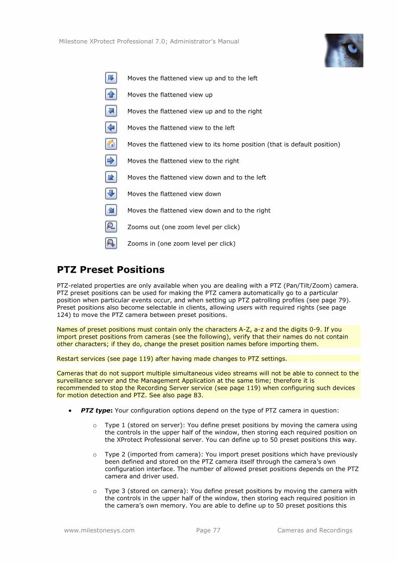
Milestone XProtect Professional 7.0; Administrator’s Manual
www.milestonesys.com Page 77 Cameras and Recordings
Moves the flattened view up and to the left
Moves the flattened view up
Moves the flattened view up and to the right
Moves the flattened view to the left
Moves the flattened view to its home position (that is default position)
Moves the flattened view to the right
Moves the flattened view down and to the left
Moves the flattened view down
Moves the flattened view down and to the right
Zooms out (one zoom level per click)
Zooms in (one zoom level per click)
PTZ Preset Positions
PTZ-related properties are only available when you are dealing with a PTZ (Pan/Tilt/Zoom) camera. PTZ preset positions can be used for making the PTZ camera automatically go to a particular position when particular events occur, and when setting up PTZ patrolling profiles (see page 79). Preset positions also become selectable in clients, allowing users with required rights (see page
124) to move the PTZ camera between preset positions. Names of preset positions must contain only the characters A-Z, a-z and the digits 0-9. If you import preset positions from cameras (see the following), verify that their names do not contain other characters; if they do, change the preset position names before importing them.
Restart services (see page 119) after having made changes to PTZ settings. Cameras that do not support multiple simultaneous video streams will not be able to connect to the surveillance server and the Management Application at the same time; therefore it is recommended to stop the Recording Server service (see page 119) when configuring such devices for motion detection and PTZ. See also page 83.
PTZ type: Your configuration options depend on the type of PTZ camera in question:
o Type 1 (stored on server): You define preset positions by moving the camera using the controls in the upper half of the window, then storing each required position on
the XProtect Professional server. You can define up to 50 preset positions this way.
o Type 2 (imported from camera): You import preset positions which have previously
been defined and stored on the PTZ camera itself through the camera’s own configuration interface. The number of allowed preset positions depends on the PTZ camera and driver used.
o Type 3 (stored on camera): You define preset positions by moving the camera with the controls in the upper half of the window, then storing each required position in the camera’s own memory. You are able to define up to 50 preset positions this
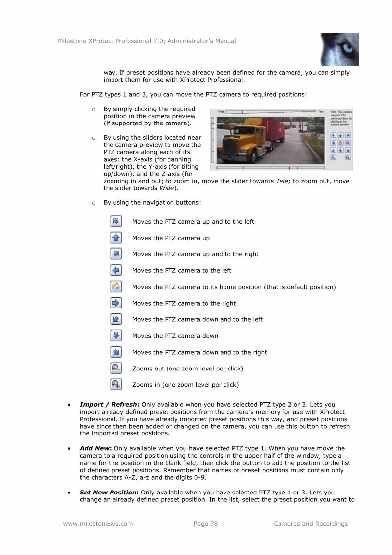
Milestone XProtect Professional 7.0; Administrator’s Manual
www.milestonesys.com Page 78 Cameras and Recordings
way. If preset positions have already been defined for the camera, you can simply import them for use with XProtect Professional.
For PTZ types 1 and 3, you can move the PTZ camera to required positions:
o By simply clicking the required position in the camera preview (if supported by the camera).
o By using the sliders located near the camera preview to move the
PTZ camera along each of its axes: the X-axis (for panning left/right), the Y-axis (for tilting up/down), and the Z-axis (for zooming in and out; to zoom in, move the slider towards Tele; to zoom out, move
the slider towards Wide).
o By using the navigation buttons:
Moves the PTZ camera up and to the left
Moves the PTZ camera up
Moves the PTZ camera up and to the right
Moves the PTZ camera to the left
Moves the PTZ camera to its home position (that is default position)
Moves the PTZ camera to the right
Moves the PTZ camera down and to the left
Moves the PTZ camera down
Moves the PTZ camera down and to the right
Zooms out (one zoom level per click)
Zooms in (one zoom level per click)
Import / Refresh: Only available when you have selected PTZ type 2 or 3. Lets you
import already defined preset positions from the camera’s memory for use with XProtect Professional. If you have already imported preset positions this way, and preset positions have since then been added or changed on the camera, you can use this button to refresh the imported preset positions.
Add New: Only available when you have selected PTZ type 1. When you have move the
camera to a required position using the controls in the upper half of the window, type a name for the position in the blank field, then click the button to add the position to the list of defined preset positions. Remember that names of preset positions must contain only the characters A-Z, a-z and the digits 0-9.
Set New Position: Only available when you have selected PTZ type 1 or 3. Lets you change an already defined preset position. In the list, select the preset position you want to
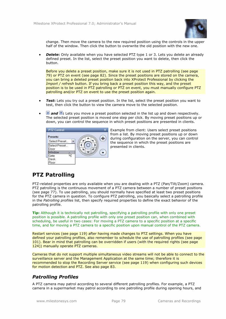
Milestone XProtect Professional 7.0; Administrator’s Manual
www.milestonesys.com Page 79 Cameras and Recordings
change. Then move the camera to the new required position using the controls in the upper half of the window. Then click the button to overwrite the old position with the new one.
Delete: Only available when you have selected PTZ type 1 or 3. Lets you delete an already defined preset. In the list, select the preset position you want to delete, then click the button.
Before you delete a preset position, make sure it is not used in PTZ patrolling (see page 79) or PTZ on event (see page 82). Since the preset positions are stored on the camera, you can bring a deleted preset position back into XProtect Professional by clicking the Import / refresh button. If you bring back a preset position this way, and the preset
position is to be used in PTZ patrolling or PTZ on event, you must manually configure PTZ patrolling and/or PTZ on event to use the preset position again.
Test: Lets you try out a preset position. In the list, select the preset position you want to test, then click the button to view the camera move to the selected position.
and : Lets you move a preset position selected in the list up and down respectively.
The selected preset position is moved one step per click. By moving preset positions up or down, you can control the sequence in which preset positions are presented in clients.
PTZ Patrolling
PTZ-related properties are only available when you are dealing with a PTZ (Pan/Tilt/Zoom) camera. PTZ patrolling is the continuous movement of a PTZ camera between a number of preset positions (see page 77). To use patrolling, you should normally have specified at least two preset positions for the PTZ camera in question. To configure PTZ patrolling, you basically select a patrolling profile in the Patrolling profiles list, then specify required properties to define the exact behavior of the
patrolling profile. Tip: Although it is technically not patrolling, specifying a patrolling profile with only one preset position is possible. A patrolling profile with only one preset position can, when combined with scheduling, be useful in two cases: For moving a PTZ camera to a specific position at a specific time, and for moving a PTZ camera to a specific position upon manual control of the PTZ camera.
Restart services (see page 119) after having made changes to PTZ settings. When you have defined your patrolling profiles, also remember to schedule the use of patrolling profiles (see page 101). Bear in mind that patrolling can be overridden if users (with the required rights (see page 124)) manually operate PTZ cameras. Cameras that do not support multiple simultaneous video streams will not be able to connect to the
surveillance server and the Management Application at the same time; therefore it is
recommended to stop the Recording Server service (see page 119) when configuring such devices for motion detection and PTZ. See also page 83.
Patrolling Profiles
A PTZ camera may patrol according to several different patrolling profiles. For example, a PTZ camera in a supermarket may patrol according to one patrolling profile during opening hours, and
Example from client: Users select preset positions from a list. By moving preset positions up or down during configuration on the server, you can control the sequence in which the preset positions are
presented in clients.
Milestone XProtect Professional 7.0; Administrator’s Manual
www.milestonesys.com Page 80 Cameras and Recordings
according to another patrolling profile when the supermarket is closed. The Patrolling profiles list lets you select which patrolling profile to configure.
Add New: Lets you add a new patrolling profile to the list. When you add a new patrolling profile, you can either give it a unique name, or reuse an existing name from another PTZ camera with PTZ patrolling.
Using several identically named patrolling profiles can be advantageous when you later configure scheduling. Example: If you have configured patrolling profiles identically named Night Patrolling on 25 different cameras, you can schedule the use of Night Patrolling on all 25 cameras in one go, even though Night Patrolling covers individual preset positions on
each of the 25 cameras.
Delete: Lets you delete an existing patrolling profile. Note that the selected patrolling
profile will be removed from the list without further warning. There are already some patrolling profiles listed, why? Names of patrolling profile defined for other cameras can be reused. This allows you to use a single patrolling profile name across several
PTZ cameras, and this can make scheduling of PTZ patrolling (see page 101) much easier. Despite the fact that several PTZ cameras share a patrolling profile name, the movement between preset positions is of course individual for each camera.
Preset Positions to Use in Patrolling Profiles
Having selected a patrolling profile in the Patrolling profiles list, you can specify which of the PTZ
camera’s preset positions should be used for the selected patrolling scheme:
1. In the Preset Positions list, select the preset positions you want to use. A preset position
can be used more than once in a patrol scheme, for example if the preset position covers an especially important location.
Tip: By pressing the CTRL button on your keyboard while selecting from the Preset Positions list, you can select several or all of list’s preset positions in one go.
2. Click the button to copy the selected preset positions to the Patrolling list.
3. The camera will move between preset positions in the sequence they appear in the
Patrolling list, starting at the preset position listed first. If you want to change the sequence
of preset positions in the Preset Positions list, select a preset position, and use the or
buttons to move the selected preset position up or down in the list. The selected preset position is moved one step per click.
If you later want to remove a preset position from the Patrolling list, select the preset position in
question, and click the button.
Wait and Transition Timing
Wait time (sec.): Lets you specify the number of seconds for which the PTZ camera
should stay at each preset position before it moves on to the next preset position. Default is 10 seconds. The wait time applies to all presets in the patrolling profile, that is the PTZ camera will stay at each preset position for the same number of seconds.
Transition time (sec.): Lets you specify the number of seconds required for the PTZ
camera to move from one preset position to another. Default is five seconds. During this transition time, motion detection is automatically disabled, as irrelevant motion is otherwise likely to be detected while the camera moves between the preset positions. After the specified number of seconds, motion detection is automatically enabled again. The transition time applies to all presets in the patrolling profile. It is thus important that
the camera is able to reach between any of the patrolling profile’s preset positions within
Milestone XProtect Professional 7.0; Administrator’s Manual
www.milestonesys.com Page 81 Cameras and Recordings
the number of seconds you specify. If not, false motion is likely to be detected. Bear in mind that it takes longer for the PTZ camera to move between positions that are located physically far apart (for example from an extreme left position to an extreme right
position) than between positions that are located physically close together. Tip: Note that wait time and transition time settings are tied to the selected patrolling profile. This allows you the flexibility of having different wait time and transition time settings for different patrolling profiles on the same camera.
PTZ Scanning
PTZ scanning (continuous panning) is supported on a few PTZ cameras only.
PTZ scanning: Only available if your camera supports PTZ scanning. Lets you enable PTZ scanning and select a PTZ scanning speed from the list below the check box.
Note that PTZ scanning only works for PTZ type 1 cameras (where preset positions are configured and stored on the XProtect Professional server). If the camera is a PTZ type 2 camera, and you import preset positions which have previously been defined and stored on the PTZ camera itself through the camera’s own configuration interface, PTZ scanning will stop working. For more information about PTZ types, see PTZ Preset Positions on page 77.
Pause and Resume PTZ Patrolling
PTZ patrolling is automatically paused when the camera is operated manually as well as if PTZ on
Event (see page 82) is used. PTZ patrolling can furthermore be paused if motion is detected. Tip: Note that pause settings are tied to the selected patrolling profile. This allows you the flexibility of having different pause settings for different patrolling profiles on the same camera.
Pause patrolling if motion is detected: To pause PTZ patrolling when motion is detected, so that the PTZ camera will remain at the position where motion was detected for a specified period of time, do the following:
1. Select the Pause patrolling schedule if motion is detected check box.
2. Select whether the PTZ camera should resume patrolling:
After a certain number of seconds has passed since first detection of
motion, regardless whether further motion is detected
- or -
After a certain number of seconds has passed without further detection of
motion
3. Specify the required number of seconds for the selected option (default is ten and five seconds respectively).
Unless transition time (see the previous information under Wait and Transition Timing ...) is set to zero, motion detection is automatically disabled while the camera moves between preset positions, as irrelevant motion is otherwise likely to be detected while the camera moves between the preset positions.
Resume PTZ patrolling after: PTZ patrolling is automatically paused when the camera is
operated manually as well as if PTZ on Event is used. You can specify how many seconds should pass before the regular patrolling is resumed after a manual or event-based interruption. Default is 30 seconds.
Milestone XProtect Professional 7.0; Administrator’s Manual
www.milestonesys.com Page 82 Cameras and Recordings
Users of the Smart Client are—in addition to manual control—able to stop a selected PTZ camera’s patrolling entirely. This takes place through a context menu in the Smart Client view. For Smart Client users, the number of seconds specified in the Patrolling settings
section therefore only applies when users manually control a PTZ camera; not when users stop a PTZ camera’s patrolling entirely. When Smart Client users stop a PTZ camera’s patrolling entirely, the camera’s patrolling will resume only when the Smart Client user selects to resume it.
PTZ on Event
PTZ-related properties are only available when you are dealing with a PTZ (Pan/Tilt/Zoom) camera. When a PTZ camera supports preset positions (see page 77), it is possible to make the PTZ camera
automatically go to a particular preset position when a particular event (see page 107) occurs. Restart services (see page 119) after having made changes to PTZ settings. Cameras that do not support multiple simultaneous video streams will not be able to connect to the surveillance server and the Management Application at the same time; therefore it is
recommended to stop the Recording Server service (see page 119) when configuring such devices for motion detection and PTZ. See also page 83. When associating events with preset positions on a PTZ camera, you are able to select between all events defined on your XProtect Professional system; you are not limited to selecting events defined on a particular hardware device.
1. In the Events list in the left side of the window, select the required event.
Tip: If you have not yet defined any suitable events, you can quickly do it: Use the Configure events list, located below the other fields.
2. In the PTZ Preset Position list in the right side of the window, select the required preset
position.
For this purpose, you can only use an event once per PTZ camera. However, different events can be used for making the PTZ camera go to the same preset position. Example:
Event 1 makes the PTZ camera go to preset position A
Event 2 makes the PTZ camera go to preset position B
Event 3 makes the PTZ camera go to preset position A If you later want to end the association between a particular event and a particular preset position, simply clear the field containing the event.
Configure When Cameras Should Do What
Use XProtect Professional’s scheduling feature to configure when:
Cameras should be online (that is transfer video to XProtect Professional)
Cameras should use speedup (that is use a higher than normal frame rate)
You want to receive any e-mail and/or SMS notifications regarding cameras
Milestone XProtect Professional 7.0; Administrator’s Manual
www.milestonesys.com Page 83 Cameras and Recordings
PTZ cameras should patrol, and according to which patrolling profile
Archiving should take place
Read more in the Configure General Scheduling & Archiving on page 95 and Configure Camera-specific Scheduling on page 97.
View Video in Management Application
You can view live video from single cameras directly in the Management Application:
1. In the Management Application’s navigation pane, expand Advanced Configuration, and expand Cameras and Storage Information.
2. Select the required camera to view live video from that camera. Above the live video, you will find a summary of the most important properties for the selected camera. Below
the live video, you will find information about the camera’s resolution and average image file size. For cameras using MPEG or H.264, you will also see the bit rate in Mbit/second.
IMPORTANT: Viewing of live video in the Management Application may under certain circumstances affect any simultaneous recording from the camera in question. Especially three
scenarios are important to consider: 1) Some cameras supporting multistreaming may halve their frame rate or respond with other negative effects when a second stream is opened. 2) If a camera delivers live video in a very high quality, de-coding of images may increase the load on the Recording Server service, which may in turn affect ongoing recordings negatively. 3) Cameras that do not support multiple simultaneous video streams will not be able to connect to the surveillance server and the Management Application at the same time; therefore it is
recommended to stop the Recording Server service (see page 119) when configuring such devices for motion detection and PTZ.
Monitor Storage Space Usage
To view how much storage space you have on your XProtect Professional system—and not least how much of it is free—do the following:
1. In the Management Application’s navigation pane, expand Advanced Configuration, and select Cameras and Storage Information.
2. View the Storage Usage Summary for information about, which drives are available, what drives are used for, the size of each drive, as well as how much video data, other data, and free space there is in each drive.
Database Resizing
In case recordings for a camera get bigger than expected, or the available drive space is suddenly reduced in another way, an advanced database resizing procedure will automatically take place:
Milestone XProtect Professional 7.0; Administrator’s Manual
www.milestonesys.com Page 84 Cameras and Recordings
If archives (see page 85) are present on the same drive as the camera’s database, the oldest archive for all cameras archived on that drive will be moved to another drive (moving archives is only possible if you use dynamic archiving (see page 59), with which you can archive to several
different drives) or—if moving is not possible—deleted. If no archives are present on the drive containing the camera’s database, the size of all camera databases on the drive will be reduced by deleting a percentage of their oldest recordings, thus temporarily limiting the size of all databases
When the Recording Server service (see page 119) is restarted upon such database resizing, the original database sizes will be used. You should therefore make sure that the drive size problem is
solved. Should the database resizing procedure take place, you will be informed on-screen in the Smart Client, in log files, and (if set up) through an e-mail and/or SMS notification.
Disable or Delete a Camera
All cameras are by default enabled. This means video from the cameras can be transferred to XProtect Professional—provided that the cameras are scheduled to be online (see page 98). To disable a camera:
1. In the Management Application’s navigation pane, expand Advanced Configuration, expand
Cameras and Storage Information, double-click the camera you want to disable, and clear the Enabled box.
2. Save your configuration changes by clicking the Save Configuration button in the Management Application’s toolbar.
To delete a camera, you technically have to delete the hardware device (see page 56). Deleting the hardware device will also delete any attached speakers and microphones. If you do not want this, consider disabling the camera instead.
Milestone XProtect Professional 7.0; Administrator’s Manual
www.milestonesys.com Page 85 Archiving
Archiving
Archiving is an integrated and automated feature that helps you store recordings beyond the capabilities of XProtect Professional’s standard database. Archiving thus maximizes storage
capacity and minimizes risk; you can keep recordings for as long as required, limited only by the available hardware storage capacity. Have you used archiving in previous XProtect Professional versions? In that case, note that
XProtect Professional now automatically archives recordings if a camera’s database becomes full. In earlier versions, this was an option configured individually for each camera. Also note that retention time is likely to affect when archiving will take place. Retention time is the total amount
of time for which you want to keep recordings from a camera (that is recordings in the camera’s database as well as any archived recordings). In earlier XProtect Professional versions, time limits were specified separately for the database and archives; now you only specify one time limit (the retention time). You specify retention time as part of the general Recording & Archiving Paths properties (see page 57). Scheduled archiving is still possible up to 24 times per day. In the following, archiving is explained in detail. If you would rather begin configuring archiving
straight away, see Configure Archiving Locations on page 91 and Configure Archiving Schedules on page 91.
Benefits of Archiving
With archiving, recordings are moved from their standard location to another location, the archiving location. With archiving, the amount of recordings you are able to store is thus limited
only by the available hardware storage capacity: By default, recordings are stored in XProtect Professional’s database for each camera. The database for each camera is capable of containing a maximum of 600000 records or 40 GB. However, the maximum size of a database is not in itself very important: If a database for a camera becomes full, XProtect Professional automatically begins archiving its content, freeing up
space in the database. Having sufficient archiving space is thus more important (see Storage Capacity Required for Archiving in the following).
In addition to automatic archiving when a database becomes full, you can schedule archiving to take place at particular times up to 24 times per day. This way, you can proactively archive recordings, so databases will never become full.
By using archiving, you will also be able to back up archived records on backup media of your choice, using your preferred backup software.
How Archiving Works
For each camera, the contents of the camera database will be moved to a default archiving folder,
called Archives. This will happen automatically if a database becomes full, and one or more times
every day, depending on your archiving settings. The default archiving folder (see page 137) is located on the XProtect Professional server, by default in C:\MediaDatabase. In the archiving folder, separate subfolders for storing archives for each camera are automatically created. These subfolders are named after the MAC address of the hardware device to which the camera is connected. Since you can keep archives spanning many
Milestone XProtect Professional 7.0; Administrator’s Manual
www.milestonesys.com Page 86 Archiving
days of recordings, and since archiving may take place several times per day, further subfolders, named after the archiving date and time, are also automatically created.
The subfolders will be named according to the following structure:
...\Archives\CameraMACAddress_VideoEncoderChannel\DateAndTime
Example: With the default archiving folder located under C:\MediaDatabase, video from an archiving taking place at 23.15 on 31st December 2009 for a camera attached to channel 2 on a video encoder hardware device with the MAC address 00408c51e181 would be stored at the following destination:
C:\MediaDatabase\Archives\00408c51e181_2\2009-12-31-23-15
If the hardware device to which the camera is attached is not a video encoder device with several channels, the video encoder channel indication in the sub-directory named after the hardware device’s MAC address will always be _1 (example: 00408c51e181_1). You are of course also able to store archives at other locations than locally in the default archiving
directory. You may, for example, specify that your archives should be stored on a network drive. When archiving to other locations than the default archiving directory, XProtect Professional will first temporarily store the archive in the local default archiving directory, then immediately move the archive to the archiving location you have specified.
While this may at first glance seem unnecessary, it greatly speeds up the archiving procedure, and reduces delays in case of network problems. Archiving directly to a network drive would mean that archiving time would vary depending on the available bandwidth on the network. First storing the archive locally, then moving it, ensures that archiving is always performed as fast as possible. If archiving to a network drive, note the regular camera database can only be stored on a local drive, that is a drive attached directly to the XProtect Professional server.
Dynamic Path Selection for Archives
With dynamic archiving paths, you specify a number of different archiving paths, usually across several drives. Using dynamic paths is highly recommended, and is the default setting when you configure cameras through the Configure Video & Recording Wizard (see page 38).
If the path containing the camera's database is on one of the drives you have selected for dynamic archiving, XProtect Professional will always try to archive to that drive first. If not, XProtect
Professional automatically archives to the archiving drive with the most available space at any time, provided there is not a camera database using that drive. Which drive has the most available space may change during the archiving process, and archiving may therefore happen to several archiving drives during the same process. This fact will have no impact on how users find and view archived recordings.
Dynamic archiving paths are general for all your cameras; you cannot configure dynamic archiving paths for individual cameras. When deciding which drives to use for dynamic archiving, consider the pros and cons in the following examples (in which we assume that the default archiving path (see page 137) is on drive
C:—drive letters are examples only, different drive letters may of course be used in your organization):
Camera records to drive C: and archives to drive C: If the path containing the camera’s database is on one of the drives you have selected for dynamic archiving, XProtect Professional will always try to archive to that drive first.
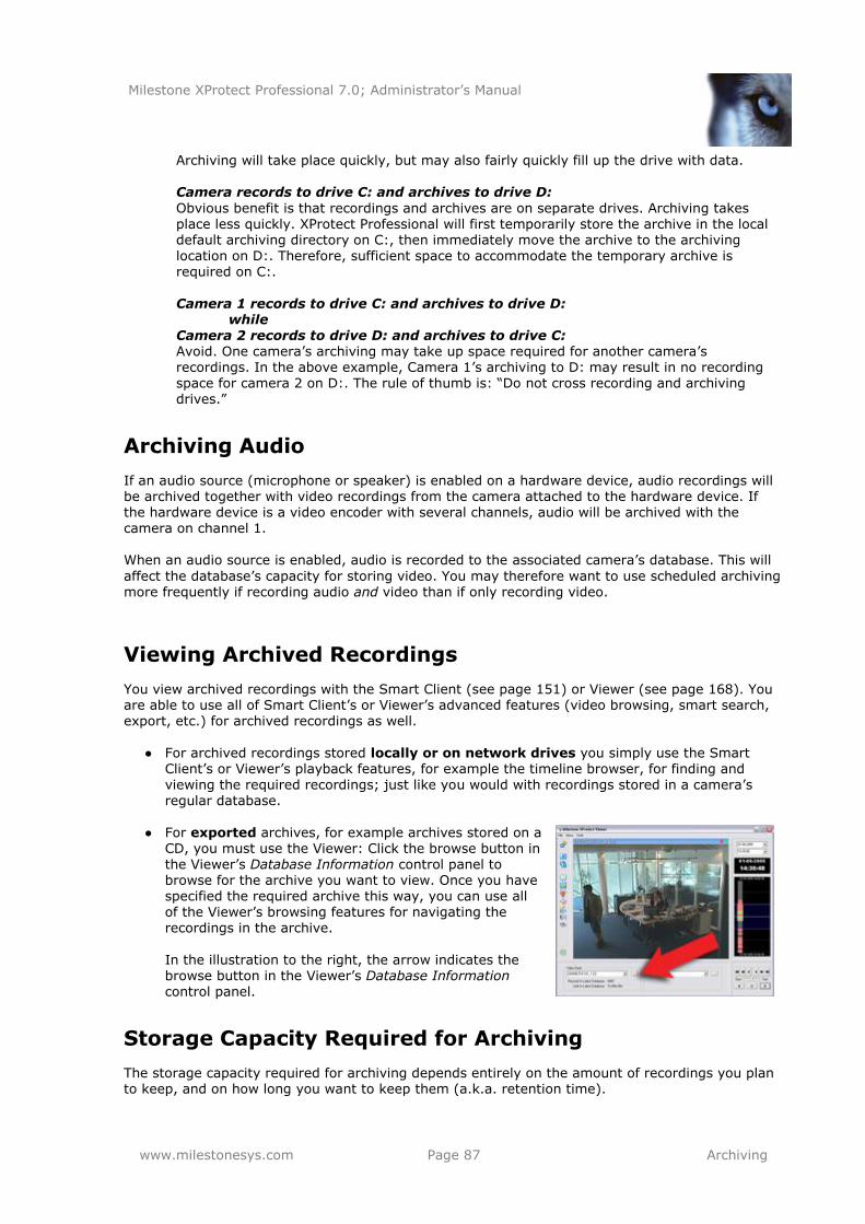
Milestone XProtect Professional 7.0; Administrator’s Manual
www.milestonesys.com Page 87 Archiving
Archiving will take place quickly, but may also fairly quickly fill up the drive with data. Camera records to drive C: and archives to drive D:
Obvious benefit is that recordings and archives are on separate drives. Archiving takes place less quickly. XProtect Professional will first temporarily store the archive in the local default archiving directory on C:, then immediately move the archive to the archiving location on D:. Therefore, sufficient space to accommodate the temporary archive is required on C:.
Camera 1 records to drive C: and archives to drive D: while
Camera 2 records to drive D: and archives to drive C: Avoid. One camera’s archiving may take up space required for another camera’s recordings. In the above example, Camera 1’s archiving to D: may result in no recording space for camera 2 on D:. The rule of thumb is: ―Do not cross recording and archiving drives.‖
Archiving Audio
If an audio source (microphone or speaker) is enabled on a hardware device, audio recordings will be archived together with video recordings from the camera attached to the hardware device. If the hardware device is a video encoder with several channels, audio will be archived with the camera on channel 1.
When an audio source is enabled, audio is recorded to the associated camera’s database. This will
affect the database’s capacity for storing video. You may therefore want to use scheduled archiving more frequently if recording audio and video than if only recording video.
Viewing Archived Recordings
You view archived recordings with the Smart Client (see page 151) or Viewer (see page 168). You are able to use all of Smart Client’s or Viewer’s advanced features (video browsing, smart search, export, etc.) for archived recordings as well.
● For archived recordings stored locally or on network drives you simply use the Smart
Client’s or Viewer’s playback features, for example the timeline browser, for finding and
viewing the required recordings; just like you would with recordings stored in a camera’s regular database.
● For exported archives, for example archives stored on a CD, you must use the Viewer: Click the browse button in the Viewer’s Database Information control panel to browse for the archive you want to view. Once you have specified the required archive this way, you can use all of the Viewer’s browsing features for navigating the recordings in the archive.
In the illustration to the right, the arrow indicates the browse button in the Viewer’s Database Information control panel.
Storage Capacity Required for Archiving
The storage capacity required for archiving depends entirely on the amount of recordings you plan to keep, and on how long you want to keep them (a.k.a. retention time).
Milestone XProtect Professional 7.0; Administrator’s Manual
www.milestonesys.com Page 88 Archiving
Some organizations want to keep archived recordings from a large number of cameras for several months or years. Other organizations may only want to archive recordings from one or two cameras, and they may want to keep their archives for much shorter periods of time.
You should always first consider the storage capacity of the local drive containing the default archiving directory to which archived recordings are always moved, even though they may immediately after be moved to an archiving location on another drive: As a rule of thumb, the capacity of the local drive should be at least twice the size required for storing the databases of all cameras.
When archiving, XProtect Professional automatically checks that space required for the data to be
archived plus 1 GB of free disk space per camera is available at the archiving location. If not, the archive location’s oldest data from the camera in question will be deleted until there is sufficient free space for the new data to be archived. In short: When estimating storage capacity required for archiving, consider your organization’s
needs, then plan for worst case rather than best case scenarios. Tip: Milestone’s Storage Calculator, found in the Support section of the Milestone website, www.milestonesys.com, can help you easily determine the storage capacity required for your surveillance system.
Backing Up Archives
Many organizations want to back up recordings from cameras, using tape drives or similar.
Creating such backups based on the content of camera databases is not recommended; it may cause sharing violations or other malfunctions. Instead, create such backups based on the content of archives. If you have not specified separate archiving locations for separate cameras, you could simply back up the default local archiving directory, Archives.
When scheduling a backup, make sure the backup job does not overlap with any scheduled archiving times.
Automatic Response if Running Out of Disk Space
With archiving, XProtect Professional can automatically respond to the threat of running out of disk space. Two scenarios can occur, depending on whether the camera database drive is different from, or identical to, the archiving drive:
Different Drives: Automatic Archiving if Database Drive Runs Out of Disk Space
In case the XProtect Professional server is running out of disk space, and
● the archiving drive is different from the camera database drive, and
● archiving has not taken place within the last hour, archiving will automatically begin in an attempt to free up disk space. This will happen regardless
of any archiving schedules.
The server is considered to be running out of disk space if:
there is less than 10% disk space left, and the available disk space goes below 30 GB plus
1.5 GB per camera
- or -
Milestone XProtect Professional 7.0; Administrator’s Manual
www.milestonesys.com Page 89 Archiving
the available disk space goes below 150 MB plus 20 MB per camera (example: with ten
cameras, the server would be running out of disk space if the remaining available disk space went below 350 MB (150 MB plus 20 MB for each of the ten cameras))
The difference ensures that very large disks will not necessarily be considered to be running out of disk space just because they have less than 10% disk space left.
On the archiving drive, XProtect Professional automatically checks that the space required for data from a camera to be archived plus 1 GB of free disk space per camera is available. If not, the archive drive’s oldest data from the camera in question will be deleted until there is sufficient free space for the new data to be archived.
IMPORTANT: You will lose the archive data being deleted.
Same Drive: Automatic Moving or Deletion of Archives if Running
Out of Disk Space
In case the XProtect Professional server is running out of disk space, and the archiving drive is identical to the camera database drive, XProtect Professional will automatically do the following in
an attempt to free up disk space:
1. First, XProtect Professional will attempt to move archives (moving archives is only possible if you use dynamic archiving, with which you can archive to several different drives). This will happen if:
● there is less than 15% disk space left, and the available disk space goes below 40
GB plus 2 GB per camera
- or -
● the available disk space goes below 225 MB plus 30 MB per camera (example: with
ten cameras, the server would be running out of disk space if the remaining available disk space went below 525 MB (225 MB plus 30 MB for each of the ten cameras))
The difference ensures that very large disks will not necessarily be considered to be running out of disk space just because they have less than 15% disk space left.
2. If moving archives is not possible, XProtect Professional will attempt to delete the oldest
archives. This will happen if:
● there is less than 10% disk space left, and the available disk space goes below 30
GB plus 1.5 GB per camera
- or -
● the available disk space goes below 150 MB plus 20 MB per camera (example: with ten cameras, the server would be running out of disk space if the remaining
available disk space went below 350 MB (150 MB plus 20 MB for each of the ten cameras))
The difference ensures that very large disks will not necessarily be considered to be running out of disk space just because they have less than 10% disk space left.
IMPORTANT: You will lose data from the archives being deleted.
3. Ultimately, if there are no archives to delete, XProtect Professional will attempt to resize
camera databases by deleting their oldest recordings. This will happen if:
● there is less than 5% disk space left, and the available disk space goes below 20 GB plus 1 GB per camera
- or -
Milestone XProtect Professional 7.0; Administrator’s Manual
www.milestonesys.com Page 90 Archiving
● the available disk space goes below 75 MB plus 10 MB per camera (example: with ten cameras, the server would be running out of disk space if the remaining available disk space went below 175 MB (75 MB plus 10 MB for each of the ten
cameras))
The difference ensures that very large disks will not necessarily be considered to be running out of disk space just because they have less than 5% disk space left. IMPORTANT: You will lose the data deleted as part of the database resizing process.
When the recording server is restarted upon such database resizing, the original database
sizes will be used. You should therefore make sure the drive size problem is solved, or adjust camera database sizes to reflect the altered drive size. Tip: Should the database resizing procedure take place, you will be informed on-screen in the Smart Client, in log files, and (if set up) through an e-mail and/or SMS notification.
New Database if Archiving Fails
Under extremely rare circumstances archiving may fail. For example, a database may be full and ready for archiving, but the operating system may lock content in the database if a content file is open. This would prevent archiving. In practice, this situation would only occur if somebody attempted to view a database file (for example a .pic file) directly from the database folder at the time of the archiving (viewing the file directly would actually not work since database content
cannot be viewed as individual files, only through the Viewer or a client, such as the Smart Client).
In such situations, the database will be put aside for archiving at a later point in time. While the database is put aside, a special temporary database is created for storage of new recordings. This way, no new recordings will be lost even though the original database is full (provided enough disk space is available for storing the special temporary database). XProtect Professional will wait for the next archiving occasion (either scheduled or because the
special temporary database also becomes full). It will then archive the content of the special temporary database, and thus free up space in it. XProtect Professional will then continue to store new recordings in the special temporary database. This will apply until the Recording Server service is restarted (see page 119). Once the service has been restarted, the content of the original database will be archived, and new recordings will again be stored in the original database. The special temporary database will also be archived, and will then cease to exist.
Can I view recordings from the special temporary database? Normally, the content of databases can be viewed through the Viewer or a client (such as the Smart Client), regardless whether the databases have been archived or not. However, the content of the special temporary database cannot be viewed through a client until the content has been archived. On the surveillance server itself, you will be able to view the content of the special temporary database through the Viewer, even if the special temporary database has not been archived yet. Since the
special temporary database will be used for storing new recordings until the Recording Server service is restarted—even though the original database may no longer be locked—you may in these extremely rare situations experience that new recordings are not viewable through clients. In that case, restarting the Recording Server service will help, since it will force the original database to again be used for storing new recordings.
Virus Scanning and Archiving
If allowed in your organization, disable any virus scanning of camera databases and archiving
locations. For more information see page 17.
Milestone XProtect Professional 7.0; Administrator’s Manual
www.milestonesys.com Page 91 Archiving
Configure Archiving Locations
Before configuring archiving locations, consider whether you want to use static or dynamic
archiving paths:
Static archiving paths mean that for a particular camera, archiving will take place to a particular location, and to that location only. Static archiving paths are in principle
individual for each camera, but they do not have to be unique: several cameras can easily use the same path if required.
You can configure static archiving paths for individual cameras, or as part of the general Recording & Archiving Paths properties.
o Individual cameras: In the Management Application’s navigation pane, expand
Advanced Configuration, expand Cameras and Storage Information, double-click the required camera, select Recording & Archiving Paths, and specify required properties (see page 71).
o General Recording & Archiving Paths: In the Management Application’s navigation pane, expand Advanced Configuration, double-click Cameras and
Storage Information, and specify required properties (see page 57).
Tip: If several cameras should use the same path, use the general Recording & Archiving Paths properties. There you get a template feature which lets you specify shared archiving
locations in just a few clicks.
Dynamic archiving paths allow greater flexibility, and are thus highly recommended. With
dynamic archiving paths, you specify a number of different archiving paths, usually across several drives. If the path containing the camera database to be archived is on one of the drives you have
selected for dynamic archiving, XProtect Professional will always try to archive to that drive first. If not, XProtect Professional automatically archives to the archiving drive with the most available space at any time, provided there is not a camera database using that drive. This fact will have no impact on how users find and view archived recordings. Dynamic archiving paths are general for all your cameras; you cannot configure dynamic archiving paths for individual cameras.
To configure archiving paths: In the Management Application’s navigation pane, expand Advanced Configuration, double-click Cameras and Storage Information, select Dynamic Path Selection - Archives, and specify required properties (see page 59).
If configuring your cameras through the Configure Video & Recording Wizard (see page 38), the
wizard also lets you configure archiving paths.
Configure Archiving Schedules
XProtect Professional automatically archives recordings if a camera’s database becomes full (in earlier versions, this was an option configured individually for each camera).
You are furthermore able to schedule archiving at particular points in time up to 24 times per day, with minimum one hour between each one. This way, you can proactively archive recordings, so databases will never become full. As a rule of thumb, the more you expect to record, the more often you should archive.

Milestone XProtect Professional 7.0; Administrator’s Manual
www.milestonesys.com Page 92 Archiving
There are two ways in which to configure archiving schedules:
While configuring your cameras through the Configure Video & Recording Wizard (see page 38), in which case you configure your archiving schedule on the wizard’s Drive selection page.
As part of the general Scheduling & Archiving Paths properties: In the Management Application’s navigation pane, expand Advanced Configuration, right-click Scheduling and Archiving, select Properties, select Archiving in the dialog, and specify required properties (see page 97).
Milestone XProtect Professional 7.0; Administrator’s Manual
www.milestonesys.com Page 93 Audio
Audio
You add cameras and other hardware devices, such as video encoders, etc., to your XProtect Professional system through the Add Hardware Devices... wizard (see page 26). If microphones
and/or speakers are attached to a hardware device, they are automatically added as well. When managing microphones and speakers in XProtect Professional, it is important to remember the basic concepts:
Microphones are attached to hardware devices, and thus typically physically located next
to cameras. They can typically record what people near a camera are saying. Operators, with the necessary rights, can then listen to these recordings through their Smart Clients (provided the computer running the Smart Client has speakers attached).
Speakers are also attached to devices, and thus also typically physically located next to
cameras. They can typically transmit information to people near a camera. Operators, with the necessary rights, can talk through such speakers using their Smart Clients (provided the computer running the Smart Client has a microphone attached).
Example: An elevator is stuck. Through a camera mounted in the elevator, Smart Client operators can see that there is an elderly lady in the elevator. A microphone attached to the camera records that the lady says: ―I am afraid; please help me out!‖ Through a speaker attached to the camera,
operators can tell the lady that: ―Help is on its way; you should be out in less than fifteen minutes.‖ When managing microphones and speakers in XProtect Professional, you thus always manage the
microphones and speakers attached to cameras; not microphones and speakers attached to Smart Client operators' computers.
Configure Microphones
Configuration of microphones in XProtect Professional is very basic; settings such as volume, etc. are controlled on the microphone units themselves.
1. In the Management Application’s navigation pane, expand Advanced Configuration, expand Hardware Devices, and expand the hardware device to which the required microphone is attached.
2. Right-click the required microphone, and select Properties.
3. Specify properties as required:
Enabled: Microphones are by default enabled, meaning that they are able to transfer audio to XProtect Professional. If required, you can disable an individual
microphone, in which case no audio will be transferred from the microphone to XProtect Professional.
Microphone name: Name of the microphone as it will appear in the Management Application as well as in clients. If required, you can overwrite the existing
microphone name with a new one. Microphone names must be unique, and must not contain any of the following special characters: < > & ' " \ / : * ? | [ ]
On some hardware devices, audio can also be enabled/disabled on the hardware device itself, typically through the hardware device’s own configuration web page. If audio on a hardware device does not work after enabling it in the Management Application, you should
Milestone XProtect Professional 7.0; Administrator’s Manual
www.milestonesys.com Page 94 Audio
thus verify whether the problem may be due to audio being disabled on the hardware device itself.
4. Save your configuration changes by clicking the Save Configuration button in the Management Application’s toolbar.
Configure Speakers
Configuration of speakers in XProtect Professional is very basic; settings such as volume, etc. are controlled on the speaker units themselves.
1. In the Management Application’s navigation pane, expand Advanced Configuration, expand
Hardware Devices, and expand the hardware device to which the required speaker is attached.
2. Right-click the required speaker, and select Properties.
3. Specify properties as required:
Enabled: Speakers are by default enabled, meaning that what is transmitted through the speakers is transferred to XProtect Professional. If required, you can
disable an individual speaker, in which case it will not be possible to say anything
through the speaker.
Speaker name: Name of the speaker as it will appear in the Management
Application as well as in clients. If required, you can overwrite the existing speaker name with a new one. Speaker names must be unique, and must not contain any of the following special characters: < > & ' " \ / : * ? | [ ]
On some hardware devices, audio can also be enabled/disabled on the hardware device itself, typically through the hardware device’s own configuration web page. If audio on a hardware device does not work after enabling it in the Management Application, you should
thus verify whether the problem may be due to audio being disabled on the hardware device itself.
4. Save your configuration changes by clicking the Save Configuration button in the
Management Application’s toolbar.
Milestone XProtect Professional 7.0; Administrator’s Manual
www.milestonesys.com Page 95 Scheduling
Scheduling
In XProtect Professional, you can configure scheduling on a general level, which also covers archiving (see page 85), as well as on a camera-specific level.
Configure General Scheduling and Archiving
XProtect Professional’s general Scheduling and Archiving feature lets you configure when:
Cameras should be online (that is transfer video to XProtect Professional)
Cameras should use speedup (that is use a higher than normal frame rate)
You want to receive any e-mail and/or SMS notifications regarding cameras
PTZ cameras should patrol, and according to which patrolling profile
Archiving should take place
Do the following:
1. In the Management Application’s navigation pane, expand Advanced Configuration, right-click Scheduling and Archiving, and select Properties.
2. Specify properties as required for Scheduling All Cameras, Scheduling Options, and Archiving. All of the properties are described on the following pages. When ready, click OK.
3. Save your configuration changes by clicking the Save Configuration button in the
Management Application’s toolbar.
Scheduling All Cameras
When you configure general scheduling and archiving, you can specify certain properties for many cameras in one go. Either simply in order to speed up things, or because the properties in question are shared by all cameras rather than specific to individual cameras.
All properties on a white background are editable; properties on a light blue background cannot be edited. Note that the properties Online Period, Speedup, E-mail Notification, SMS Notification, and PTZ Patrolling can also be specified individually for each camera.
Template: The template can help you configure similar properties quickly. Say you have
50 cameras and you want to change the online schedule profile for all of them. Instead of having to select the same 50 times, you can simply enter them once in the template, and then apply the template to the 50 cameras with only two clicks.
Apply Template: Lets you select which cameras you want to apply the template for. You
then use one of the two Set buttons (see descriptions in the following) to actually apply the template. Tip: To select all cameras in the list, click the Select All button.
Camera: Name of each camera as it will appear in the Management Application as well as in clients.
Milestone XProtect Professional 7.0; Administrator’s Manual
www.milestonesys.com Page 96 Scheduling
Online: Lets you select the required profile (for example Always on) for the online
schedule (see page 98) for the camera(s) in question. Tip: If you lack a suitable profile, use the New schedule profile feature (described in the following) to configure one. This applies for the other schedule types as well.
Speedup: Lets you select the required profile for the speedup schedule (see page 99) for
the camera(s) in question.
E-mail: Lets you select the required profile for the e-mail notification schedule (see page
100) for the camera(s) in question.
SMS: Lets you select the required profile for the SMS (mobile phone text message)
notification schedule (see page 100) for the camera(s) in question.
PTZ Patrolling: Only available for PTZ (Pan/Tilt/Zoom) cameras with patrolling, the continuous movement of a PTZ camera between a number of preset positions. Lets you
select the required profile for the PTZ patrolling schedule (see page 101) for the camera(s) in question.
Select All: Click button to select all cameras in the Apply Template column.
Clear All: Click button to clear all selections in the Apply Template column
Set selected template value on selected cameras: Lets you apply only a selected value
from the template to selected cameras.
New schedule profile: Lets you create a new schedule profile of any type by clicking the
Create... button.
Scheduling Options
Start cameras on client requests: Cameras may be offline, for example because they
have reached the end of an online schedule (see page 98), in which case client users will not be able to view live video from the cameras. However, if you select Start cameras on client requests, client users will be able to start the camera (technically: force the camera
to be online outside its online schedule) in order to view live video from the camera.
Schedule profile for new cameras: Lets you select which online schedule profile to use
as default for cameras you subsequently add to your XProtect Professional system. Note that your selection only applies for the online schedule, not for any other schedules. Default selection is Always on, meaning that new cameras will always be online, that is transferring video to the XProtect Professional server for live viewing and further
processing.
Maximum delay between reconnect attempts: Lets you control the aggressiveness of reconnection attempts. If XProtect Professional loses the connection to a camera, it will by
default attempt to re-establish the connection after ten seconds. In some environments, for example if using vehicle-mounted cameras through wireless connections, camera connections may frequently be lost, and you may want to change the aggressiveness of
such reconnection attempts.
Milestone XProtect Professional 7.0; Administrator’s Manual
www.milestonesys.com Page 97 Scheduling
Archiving
XProtect Professional automatically archives recordings if a camera’s database becomes full (in earlier versions, this was an option configured individually for each camera; read more about
archiving on page 85). You are furthermore able to schedule archiving at particular points in time every day. This way, you can proactively archive recordings, so databases will never become full. As a rule of thumb, the more you expect to record, the more often you should archive.
Archiving Time
The Archiving Times list shows the times at which you want to automatically archive the content of
all camera databases on your XProtect Professional server. You can do this up to 24 times per day, with minimum one hour between each one. To add archiving times to the list:
1. Specify required time in the time box to the right of the Archiving Times list. You specify the required time by selecting the hour, minute and second values respectively, then
clicking the up and down buttons to increase or decrease values. Alternatively, you can simply overwrite selected hour, minute or second values.
2. Click the Add button.
Archive Failure Notification
You can automatically get notified if archiving fails:
Send e-mail on archiving failure: If selected, XProtect Professional will automatically send an e-mail to selected recipients if archiving fails. This requires that the e-mail notification feature (see page 103) is enabled. Recipients are defined as part of the e-mail
notification properties.
Send SMS on archiving failure: If selected, XProtect Professional will automatically send an SMS (mobile phone text message) to selected recipients if archiving fails. This requires that the SMS notification feature (see page 105) is enabled. Recipients are defined as part
of the SMS notification properties.
E-mail and SMS notifications are normally only sent during scheduled periods (see page 100). However, archiving failures are considered to be so serious that, if enabled, e-mail and SMS notifications regarding archiving failures are sent regardless of schedules.
Configure Camera-specific Scheduling
With camera-specific scheduling, you can configure when:
A camera should be online (that is transfer video to XProtect Professional)
A camera should use speedup (that is use a higher than normal frame rate)
You want to receive any e-mail and/or SMS notifications regarding the camera
If the camera is a PTZ camera able to patrol: when it should patrol, and according to which
patrolling profile Do the following:
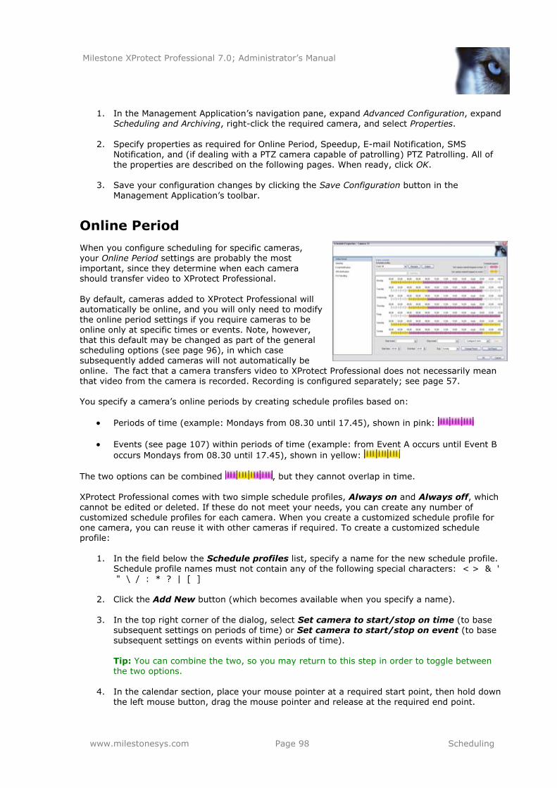
Milestone XProtect Professional 7.0; Administrator’s Manual
www.milestonesys.com Page 98 Scheduling
1. In the Management Application’s navigation pane, expand Advanced Configuration, expand
Scheduling and Archiving, right-click the required camera, and select Properties.
2. Specify properties as required for Online Period, Speedup, E-mail Notification, SMS
Notification, and (if dealing with a PTZ camera capable of patrolling) PTZ Patrolling. All of the properties are described on the following pages. When ready, click OK.
3. Save your configuration changes by clicking the Save Configuration button in the
Management Application’s toolbar.
Online Period
When you configure scheduling for specific cameras, your Online Period settings are probably the most important, since they determine when each camera should transfer video to XProtect Professional.
By default, cameras added to XProtect Professional will automatically be online, and you will only need to modify the online period settings if you require cameras to be online only at specific times or events. Note, however, that this default may be changed as part of the general scheduling options (see page 96), in which case
subsequently added cameras will not automatically be
online. The fact that a camera transfers video to XProtect Professional does not necessarily mean that video from the camera is recorded. Recording is configured separately; see page 57. You specify a camera’s online periods by creating schedule profiles based on:
Periods of time (example: Mondays from 08.30 until 17.45), shown in pink:
Events (see page 107) within periods of time (example: from Event A occurs until Event B
occurs Mondays from 08.30 until 17.45), shown in yellow:
The two options can be combined , but they cannot overlap in time.
XProtect Professional comes with two simple schedule profiles, Always on and Always off, which
cannot be edited or deleted. If these do not meet your needs, you can create any number of customized schedule profiles for each camera. When you create a customized schedule profile for one camera, you can reuse it with other cameras if required. To create a customized schedule profile:
1. In the field below the Schedule profiles list, specify a name for the new schedule profile.
Schedule profile names must not contain any of the following special characters: < > & ' " \ / : * ? | [ ]
2. Click the Add New button (which becomes available when you specify a name).
3. In the top right corner of the dialog, select Set camera to start/stop on time (to base subsequent settings on periods of time) or Set camera to start/stop on event (to base subsequent settings on events within periods of time).
Tip: You can combine the two, so you may return to this step in order to toggle between the two options.
4. In the calendar section, place your mouse pointer at a required start point, then hold down
the left mouse button, drag the mouse pointer and release at the required end point.
Milestone XProtect Professional 7.0; Administrator’s Manual
www.milestonesys.com Page 99 Scheduling
You specify each day separately.
You specify time in increments of five minutes; XProtect Professional helps you by showing the time over which your mouse pointer is
positioned.
If you base your schedule profile—or parts of it—on events within periods of time, remember to select Start event and Stop event from the lists below the calendar section.
Tip: If you have not yet defined any suitable events, you can quickly do it: Use the
Configure events list, located below the other fields.
To delete an unwanted part of a schedule profile, right-click it and select Delete.
To quickly fill or clear an entire day, double-click the name of the day.
As an alternative to dragging inside the calendar section, use the Start time, End time and Day fields, then the Change Period or Set Period button as required. When using the Start time and End time fields, remember that time is specified in increments of five minutes. You cannot specify a period shorter than five minutes,
and you can only use times like 12:00, 12.05, 12:10, 12:15, etc. If you specify a time outside of the five-minute intervals, such as 12:13, you will get an error message.
Speedup
When you configure scheduling for specific MJPEG cameras, you can specify speedup periods. Before you can define this type of schedule, speedup must be enabled (see page 62). You specify a camera’s speedup periods by creating schedule profiles based on periods of time (example:
Mondays from 08.30 until 17.45), shown in olive green:
Speedup may also take place based on events, but that is configured elsewhere: See Frame Rate - MJPEG (General Recording & Storage Properties) on page 64 and Frame Rate (Camera-specific Properties) on page 68. XProtect Professional comes with two simple schedule profiles, Always on and Always off, which
cannot be edited or deleted. If these do not meet your needs, you can create any number of customized schedule profiles for each camera. When you create a customized schedule profile for one camera, you can reuse it with other cameras if required. To create a customized schedule profile:
1. In the field below the Schedule profiles list, specify a name for the new schedule profile. Schedule profile names not contain any of the following special characters: < > & ' " \ /
: * ? | [ ]
2. Click the Add New button (which becomes available when you specify a name).
3. In the calendar section, place your mouse pointer at a required start point, then hold down the left mouse button, drag the mouse pointer and release at the required end point.
You specify each day separately.
You specify time in increments of five minutes; XProtect
Professional helps you by showing the time over which your mouse pointer is positioned.
Milestone XProtect Professional 7.0; Administrator’s Manual
www.milestonesys.com Page 100 Scheduling
To delete an unwanted part of a schedule profile, right-click it and select Delete.
To quickly fill or clear an entire day, double-click the name of the day.
As an alternative to dragging inside the calendar section, use the Start time, End time and Day fields, then the Change Period or Set Period button as required. When using the Start time and End time fields, remember that time is specified in increments of five minutes. You cannot specify a period shorter than five minutes, and you can only use times like 12:00, 12.05, 12:10, 12:15, etc. If you specify a
time outside of the five-minute intervals, such as 12:13, you will get an error message.
E-mail Notification
When you configure scheduling for specific cameras, you can specify e-mail notification periods. Before you can define this type of schedule, e-mail notification must be enabled (see page 103). You specify a camera’s e-mail notification periods by creating schedule profiles based on periods of
time (example: Mondays from 08.30 until 17.45), shown in blue:
XProtect Professional comes with two simple schedule profiles, Always on and Always off, which cannot be edited or deleted. If these do not meet your needs, you can create any number of customized schedule profiles for each camera. When you create a customized schedule profile for one camera, you can reuse it with other cameras if required. To create a customized schedule profile:
1. In the field below the Schedule profiles list, specify a name for the new schedule profile. Schedule profile names not contain any of the following special characters: < > & ' " \ / : * ? | [ ]
2. Click the Add New button (which becomes available when you specify a name).
3. In the calendar section, place your mouse pointer at a required start point, then hold down
the left mouse button, drag the mouse pointer and release at the required end point.
You specify each day separately.
You specify time in increments of five minutes; XProtect
Professional helps you by showing the time over which your mouse pointer is positioned.
To delete an unwanted part of a schedule profile, right-click it and select Delete.
To quickly fill or clear an entire day, double-click the name of the day.
As an alternative to dragging inside the calendar section, use the Start time, End time and Day fields, then the Change Period or Set Period button as required.
When using the Start time and End time fields, remember that time is specified in increments of five minutes. You cannot specify a period shorter than five minutes, and you can only use times like 12:00, 12.05, 12:10, 12:15, etc. If you specify a time outside of the five-minute intervals, such as 12:13, you will get an error message.
SMS Notification
When you configure scheduling for specific cameras, you can specify SMS (mobile phone text
message) notification periods. Before you can define this type of schedule, SMS notification must be enabled (see page 105). You specify a camera’s SMS notification periods by creating schedule
Milestone XProtect Professional 7.0; Administrator’s Manual
www.milestonesys.com Page 101 Scheduling
profiles based on periods of time (example: Mondays from 08.30 until 17.45), shown in green:
XProtect Professional comes with two simple schedule profiles, Always on and Always off, which cannot be edited or deleted. If these do not meet your needs, you can create any number of customized schedule profiles for each camera. When you create a customized schedule profile for one camera, you can reuse it with other cameras if required. To create a customized schedule profile:
1. In the field below the Schedule profiles list, specify a name for the new schedule profile.
Schedule profile names not contain any of the following special characters: < > & ' " \ / : * ? | [ ]
2. Click the Add New button (which becomes available when you specify a name).
3. In the calendar section, place your mouse pointer at a required start point, then hold down
the left mouse button, drag the mouse pointer and release at the required end point.
You specify each day separately.
You specify time in increments of five minutes; XProtect
Professional helps you by showing the time over which your mouse pointer is positioned.
To delete an unwanted part of a schedule profile, right-click it and select Delete.
To quickly fill or clear an entire day, double-click the name of the day.
As an alternative to dragging inside the calendar section, use the Start time, End time and Day fields, then the Change Period or Set Period button as required. When using the Start time and End time fields, remember that time is specified in
increments of five minutes. You cannot specify a period shorter than five minutes, and you can only use times like 12:00, 12.05, 12:10, 12:15, etc. If you specify a time outside of the five-minute intervals, such as 12:13, you will get an error message.
PTZ Patrolling
When you configure scheduling for PTZ (Pan/Tilt/Zoom) cameras capable of patrolling (see page
79), you can specify which patrolling profiles to use at specific times. Before you can define this
type of schedule, patrolling must be configured for the cameras in question. Patrolling schedule profiles are based on use of particular patrolling profiles within particular
periods of time (example: Mondays from 08.30 until 17.45), shown in red:
Use of one patrolling profile may be followed immediately by use of another (example: use the Daytime patrolling profile Mondays from 08.30 until 17.45, then the Evening patrolling profile Mondays from 17.45 until 23.00). Use of two patrolling profiles cannot overlap.
Unlike other types of scheduling, there are no ready-made Always on and Always off schedule profiles for PTZ patrolling. You can create any number of customized schedule profiles for each camera. When you create a customized schedule profile for one camera, you can reuse it with other cameras if required. To create a customized schedule profile:
1. In the field below the Schedule profiles list, specify a name for the new schedule profile. Schedule profile names not contain any of the following special characters: < > & ' " \ / : * ? | [ ]
2. Click the Add New button (which becomes available when you specify a name).
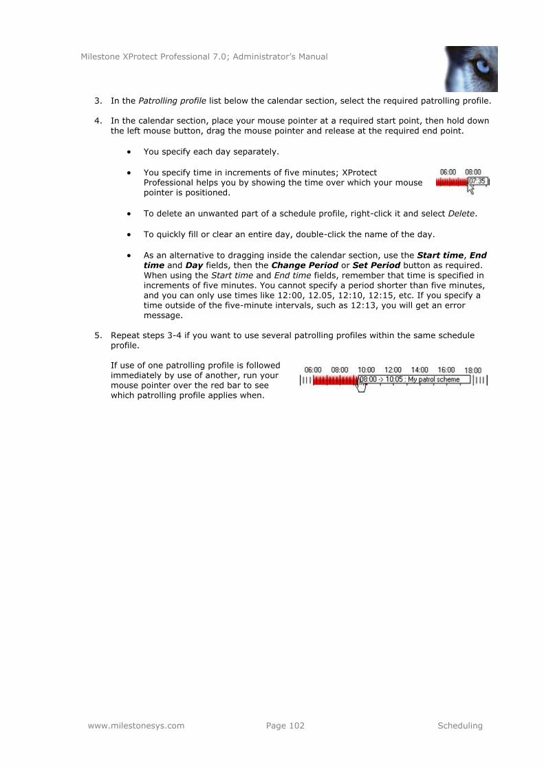
Milestone XProtect Professional 7.0; Administrator’s Manual
www.milestonesys.com Page 102 Scheduling
3. In the Patrolling profile list below the calendar section, select the required patrolling profile.
4. In the calendar section, place your mouse pointer at a required start point, then hold down
the left mouse button, drag the mouse pointer and release at the required end point.
You specify each day separately.
You specify time in increments of five minutes; XProtect Professional helps you by showing the time over which your mouse pointer is positioned.
To delete an unwanted part of a schedule profile, right-click it and select Delete.
To quickly fill or clear an entire day, double-click the name of the day.
As an alternative to dragging inside the calendar section, use the Start time, End time and Day fields, then the Change Period or Set Period button as required.
When using the Start time and End time fields, remember that time is specified in increments of five minutes. You cannot specify a period shorter than five minutes, and you can only use times like 12:00, 12.05, 12:10, 12:15, etc. If you specify a time outside of the five-minute intervals, such as 12:13, you will get an error message.
5. Repeat steps 3-4 if you want to use several patrolling profiles within the same schedule
profile. If use of one patrolling profile is followed immediately by use of another, run your mouse pointer over the red bar to see which patrolling profile applies when.
Milestone XProtect Professional 7.0; Administrator’s Manual
www.milestonesys.com Page 103 E-mail and SMS (Mobile Text)
E-mail and SMS (Mobile Text)
Configure E-mail Notifications
With e-mail notifications, you and your colleagues can instantly get notified when your surveillance system requires attention. XProtect Professional can automatically send e-mail notifications to one or more recipients when:
Motion (see page 74) is detected
Events (see page 107) occur (you can select individually for each event whether you want
to receive an e-mail notification or not, thus avoiding irrelevant e-mails)
Archiving (see page 85) fails (if e-mail notification has been selected as part of the
scheduling properties for archiving, see page 97) Do the following:
1. In the Management Application’s Navigation pane, expand Advanced Configuration, right-click E-mail and select Properties.
2. You enable the use of e-mail alerts separately for the Recording Server service and—if
applicable—the Viewer.
Enable e-Mail (Recording Server): Enables e-mail notifications whenever the
Recording Server service (see page 122) is running. E-mail notifications will then be sent when the following conditions apply:
o the Recording Server service is running
o motion is detected or an event, for which the sending of an e-mail
notification has been defined, occurs
o motion is detected within a period of time for which an e-mail notification schedule has been defined
Enable e-Mail (Viewer): Enables e-mail notifications in the Viewer (see page
168). In effect, this will display the E-Mail Report button in the Viewer’s toolbar, enabling users to send evidence via e-mail. Use of the e-mail feature is only possible when the Viewer is run on the surveillance system server itself; not in a
Viewer exported with video evidence. If e-mail alerts are enabled for the Viewer, the content you specify in the Recipient(s), Subject text and Message text fields will appear as default values in the Viewer’s dialog for sending evidence via e-mail. Viewer users will be able to overwrite these default values.
3. Specify required properties, including the important information about which SMTP mail
server to use. The properties are described on the following pages. When ready, click OK.
Tip: You can test your e-mail notification configuration by clicking the Test button; this will send a test e-mail to the specified recipients.
4. Save your configuration changes by clicking the Save Configuration button in the Management Application’s toolbar.
When configuring e-mail alerts, also consider the e-mail notification schedules (see page 100) configured for each camera.
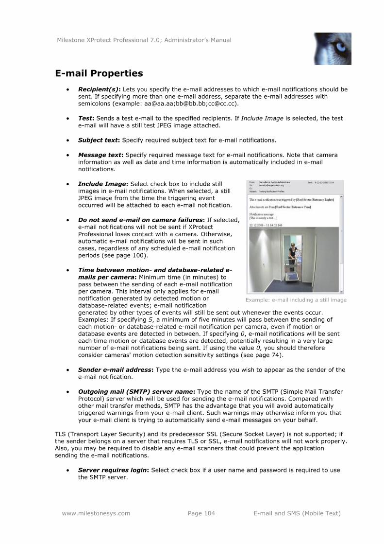
Milestone XProtect Professional 7.0; Administrator’s Manual
www.milestonesys.com Page 104 E-mail and SMS (Mobile Text)
E-mail Properties
Recipient(s): Lets you specify the e-mail addresses to which e-mail notifications should be
sent. If specifying more than one e-mail address, separate the e-mail addresses with semicolons (example: [email protected];[email protected];[email protected]).
Test: Sends a test e-mail to the specified recipients. If Include Image is selected, the test
e-mail will have a still test JPEG image attached.
Subject text: Specify required subject text for e-mail notifications.
Message text: Specify required message text for e-mail notifications. Note that camera information as well as date and time information is automatically included in e-mail notifications.
Include Image: Select check box to include still images in e-mail notifications. When selected, a still JPEG image from the time the triggering event
occurred will be attached to each e-mail notification.
Do not send e-mail on camera failures: If selected, e-mail notifications will not be sent if XProtect
Professional loses contact with a camera. Otherwise, automatic e-mail notifications will be sent in such
cases, regardless of any scheduled e-mail notification periods (see page 100).
Time between motion- and database-related e-
mails per camera: Minimum time (in minutes) to pass between the sending of each e-mail notification per camera. This interval only applies for e-mail notification generated by detected motion or database-related events; e-mail notification
generated by other types of events will still be sent out whenever the events occur. Examples: If specifying 5, a minimum of five minutes will pass between the sending of each motion- or database-related e-mail notification per camera, even if motion or database events are detected in between. If specifying 0, e-mail notifications will be sent each time motion or database events are detected, potentially resulting in a very large
number of e-mail notifications being sent. If using the value 0, you should therefore consider cameras' motion detection sensitivity settings (see page 74).
Sender e-mail address: Type the e-mail address you wish to appear as the sender of the e-mail notification.
Outgoing mail (SMTP) server name: Type the name of the SMTP (Simple Mail Transfer Protocol) server which will be used for sending the e-mail notifications. Compared with other mail transfer methods, SMTP has the advantage that you will avoid automatically triggered warnings from your e-mail client. Such warnings may otherwise inform you that
your e-mail client is trying to automatically send e-mail messages on your behalf.
TLS (Transport Layer Security) and its predecessor SSL (Secure Socket Layer) is not supported; if the sender belongs on a server that requires TLS or SSL, e-mail notifications will not work properly.
Also, you may be required to disable any e-mail scanners that could prevent the application sending the e-mail notifications.
Server requires login: Select check box if a user name and password is required to use the SMTP server.
Example: e-mail including a still image
Milestone XProtect Professional 7.0; Administrator’s Manual
www.milestonesys.com Page 105 E-mail and SMS (Mobile Text)
Username: Only required when Server requires login is selected. Specify the user name
required for using the SMTP server.
Password: Only required when Server requires login is selected. Specify the password
required for using the SMTP server.
Configure SMS Notifications
With SMS (mobile phone text message) notifications, you—or a colleague—can instantly get notified when your surveillance system requires attention. XProtect Professional can automatically send SMS notifications to one or more recipients when:
Motion (see page 74) is detected
Events (see page )107 occur; you can select individually for each event whether you want
to receive an e-mail notification or not, thus avoiding irrelevant SMS messages
Archiving (see page 85) fails, provided SMS notification has been selected as part of the
archiving properties (see page 97)) Use of the SMS notification feature requires that an external Siemens TC-35 GSM modem has been attached to a serial port (a.k.a. COM port) on the XProtect Professional server. Siemens TC-35 is a
dual-band EGSM900/GSM1800 modem; verify that the modem is compatible with mobile phone
networks where you are going to use it with XProtect Professional. To configure SMS notifications, do the following:
1. In the Management Application’s Navigation pane, expand Advanced Configuration, right-click SMS and select Properties.
2. Enable the use of SMS by selecting the Enable SMS check box.
3. Specify required properties. The properties are described on the following pages.
Tip: You can test your SMS notification configuration by clicking the Test button; this will
send a test SMS to the specified recipient. Note that you must stop the Recording Server service (see page 119) while you perform the test (remember to start the service again
afterwards).
When ready, click OK.
4. Save your configuration changes by clicking the Save Configuration button in the
Management Application’s toolbar. When configuring SMS alerts, also consider the SMS notification schedules (see page 100) configured for each camera.
SMS Properties
GSM modem connected to: Select port connecting the XProtect Professional server to the
GSM modem.
SIM card PIN code: Specify PIN code for the SIM card inserted in the GSM modem.
SIM card PUK code: Specify PUK code (that is unlocking code) for the SIM card inserted in the GSM modem.
Milestone XProtect Professional 7.0; Administrator’s Manual
www.milestonesys.com Page 106 E-mail and SMS (Mobile Text)
SMS central phone number: Specify the number of the SMS central to which the GSM
modem should connect in order to send SMS notifications.
Recipient phone number: Specify the number of the mobile telephone to which SMS
alerts should be sent. It is only possible to send SMS notifications to a single telephone number.
Message: Specify required message text for the SMS notification. Message text must be no longer that 160 characters, and must only contain the following characters: a-z, A-Z, 0-
9 as well as commas (,) and full stops (.). Note that camera information as well as date and time information is automatically included in SMS notifications.
Tip: While you write, the counter below the Message fields indicates how many characters you have left to use.
Time between motion- and database-related SMSs per camera: Minimum time (in minutes) to pass between the sending of each SMS notification per camera. This interval only applies for SMS notification generated by detected motion or database-related events; SMS notification generated by other types of events will still be sent out whenever the
events occur. Examples: If specifying 5, a minimum of five minutes will pass between the sending of each motion- or database-related SMS notification per camera, even if motion or database events are detected in between. If specifying 0, SMS notifications will be sent each time motion or database events are detected, potentially resulting in a very large number of SMS notifications being sent. If using the value 0, you should therefore consider cameras' motion detection sensitivity settings (see page 74).
Test: Lets you test your SMS notification configuration by sending a test SMS to the specified recipient. Note that you must stop the Recording Server service (see page 119) while you perform the test (remember to start the service again afterwards).
Do not send SMS on camera failures: If selected, SMS notifications will not be sent if XProtect Professional loses contact with a camera. Otherwise, automatic SMS notifications will be sent in such cases, regardless of any scheduled SMS notification periods (see page 100).
Milestone XProtect Professional 7.0; Administrator’s Manual
www.milestonesys.com Page 107 Events, Input and Output
Events, Input and Output
Hardware input, such as door sensors, etc. can be attached to input ports on hardware devices. Input from such external hardware input units can be used for generating events in XProtect
Professional. Events of various types (see the following for details) can be used for automatically triggering actions in XProtect Professional. Examples of actions: starting or stopping recording on cameras,
switching to a particular video frame rate, triggering e-mail or SMS notifications, making PTZ cameras move to specific preset positions, etc. Events can also be used for activating hardware output.
Hardware output units can be attached to output ports on many hardware devices, allowing you to activate lights, sirens, etc. from XProtect Professional. Such hardware output can be activated automatically by events, or manually from clients. The following types of events exist:
Hardware input events: Events based on input from hardware input units attached to hardware devices are called hardware input events. Some hardware devices have their own capabilities for detecting motion, for detecting
moving and/or static objects, etc. (configured in the hardware devices' own software; typically by accessing a browser-based configuration interface on the hardware device’s IP address). When this is the case, XProtect Professional considers such detections as input from the hardware, and you can use such detections as input events as well. Lastly, hardware input events can be based on XProtect Professional detecting motion in video from a camera, based on motion detection settings (see page 74). This type of
hardware input events is also called system motion detection events or VMD (Video Motion Detection) events. In earlier XProtect Professional versions, VMD events were an event type of their own; now they are simply considered a type of hardware input event.
Manual events: Events may be generated manually by users selecting them in their
clients. These events are called manual events.
Generic events: Input may also be received in the form of TCP or UDP data packages,
which can be analyzed by XProtect Professional, and—if matching specified criteria—used to generate events. Such events are called generic events.
Timer events: Timer events are separate events, triggered by the hardware input event or
manual event or generic event under which they are defined. Timer events occur a specified number of seconds or minutes after the event under which they are defined has occurred. Timer events may be used for a wide variety of purposes, typically for stopping previously triggered actions. Examples:
o A camera starts recording based on a hardware input event, for example when a door is opened; a timer event stops the recording after 15 seconds
o Lights are switched on and a camera starts recording based on a manual event; a
timer event stops the recording after one minute, and another timer event switches the lights off after two minutes
VMD events; where are they? In previous versions of XProtect Professional, an event type called
VMD events existed. VMD (Video Motion Detection) events were based on the XProtect Professional system detecting motion in the video stream from a camera. This is still possible, but now you configure such events as hardware input events.
Milestone XProtect Professional 7.0; Administrator’s Manual
www.milestonesys.com Page 108 Events, Input and Output
You do not have to configure hardware input units separately; any hardware input units connected to hardware devices are automatically detected when you add the hardware devices to XProtect Professional. The same goes for hardware output, but hardware output does require some simple
configuration in XProtect Professional. Before configuring events of any type, configure general event handling, such as which ports XProtect Professional should use for event data. Normally, you can just use the default values, but it is a good idea to verify that your organization is not already using the ports for other purposes. See Configure General Event Handling in the following.
When you are ready to configure events, see Add a Hardware Input Event on page 109, Add a
Manual Event on page 110 and Add a Generic Event on page 111. If you want to use timer events with your other events, see Add a Timer Event on page 116. If you want to configure hardware output and automatically trigger output when events occur, so that, for example, lights are switched on when a door is opened or when motion is
detected in video, see Add a Hardware Output on page 117 and Configure Hardware Output on Event on page 118.
Configure General Event Handling
Before configuring events of any type, configure general event handling, such as which ports
XProtect Professional should use for event data. Normally, you can just use the default values, but it is a good idea to verify that your organization is not already using the ports for other purposes.
1. In the Management Application’s navigation pane, expand Advanced Configuration, right-
click Events and Output, and select Properties.
2. Specify required properties:
Alert and generic event port: Lets you specify port number to use for handling events, including generic events (see page 111). Default port is port 1234.
SMTP event port: Lets you specify port number to use for sending event
information from hardware devices to XProtect Professional via SMTP. Default port is port 25.
FTP event port: Lets you specify port number to use for sending event
information from hardware devices to XProtect Professional via FTP. Default port is port 21.
Polling interval [1/10] second: For a small number of hardware devices,
primarily dedicated input/output devices (see page 55), it is necessary for XProtect Professional to regularly check the state of the hardware devices' input ports in order to detect input. Such state checking at regular intervals is called polling. You can specify (in tenths of a second) the interval between state checks. Default value is 10 tenths of a second (that is one second). For dedicated input/output devices, it
is highly recommended that the polling frequency is set to the lowest possible value (one tenth of a second between state checks). For information about which hardware devices require polling, see the release note.
When ready, click OK.
3. Save your configuration changes by clicking the Save Configuration button in the
Management Application’s toolbar.
Milestone XProtect Professional 7.0; Administrator’s Manual
www.milestonesys.com Page 109 Events, Input and Output
Add a Hardware Input Event
With hardware input events, you can turn input received from input units attached to hardware
devices into events in XProtect Professional. Before you specify input for a hardware device, verify that sensor operation is recognized by the hardware device. Most hardware devices are capable of showing this in their configuration interfaces, or via CGI script commands. Also check the release notes to verify that input-controlled operation is supported for the hardware device and firmware used.
To add and/or configure a hardware input event, do the following:
1. In the Management Application’s navigation pane, expand Advanced Configuration, then expand Events and Output. Right-click Hardware Input Events and select Enable New Input Event.
2. In the Hardware Input Event Properties window’s list of hardware devices, expand the required hardware device to see a list of pre-defined hardware input.
3. Select the required types of input to use them as events. The types of input often vary from camera to camera. If motion detection (see page 74) is enabled for the camera in question, note the input type System Motion Detection, which lets you turn detected motion in the camera’s video stream into an event. In earlier XProtect Professional
versions, this was known as a VMD event.
Note that some types of input are mutually exclusive. When you select one type of input, you may therefore note that other types of input become unavailable for selection.
4. For each selected type of input, select required properties. All of the properties are
described in the following.
5. When ready, click OK, or click the Add button to add a timer event (see page 116) to the event you have just created.
6. Save your configuration changes by clicking the Save Configuration button in the Management Application’s toolbar.
Hardware Input Properties
Note that some properties depend on the selected type of input.
Enable: Select check box to use selected type of input as an event in XProtect
Professional, and specify further properties.
Event name: Specify a name for the event. Hardware input event names must be unique, and must not contain the following characters: < > & ' " \ / : * ? | [ ]
Some cameras only support event names of a certain length and/or with a certain structure. Refer to the camera’s documentation for exact details.
Images from camera: Only relevant if using pre- and post-alarm images, a feature
available for selected cameras only; it enables sending of images from immediately before an event took place from the camera to the surveillance system via e-mail. Pre- and post-alarm images should not be confused with XProtect Professional’s own pre- and post-recording feature (see page 70). Lets you select which camera you want to receive pre- and/or post-alarm images from.
Milestone XProtect Professional 7.0; Administrator’s Manual
www.milestonesys.com Page 110 Events, Input and Output
Number of pre-alarm images: Only relevant if using pre-alarm images, a feature
available for selected cameras only. Specify required number of pre-alarm images. Allowed number may differ from camera to camera; allowed range is displayed to the right of the field.
Frames per second: Only relevant if using pre-alarm images, a feature available for
selected cameras only. Specify required frame rate. Used in combination with the Number of pre-alarm images field, this field indirectly allows you to control how long before the event you want to receive pre-alarm images from.
Send e-mail if this event occurs: Only available if e-mail notification (see page 103) is
enabled. Select if XProtect Professional should automatically send an e-mail when the event occurs. Recipients are defined as part of the e-mail notification configuration. When using e-mail notifications, also bear in mind individual cameras' scheduling (see page 100).
Attach image from camera: Only available if e-mail notification (see page 103) is enabled. Select to include an image—recorded at the time the event is triggered—in the e-mail notification, then select the required camera in the list next to the check box.
Send SMS if this event occurs: Only available if SMS (mobile phone text message) notification (see page 105) is enabled. Select if XProtect Professional should automatically send an SMS when the event occurs. Recipients are defined as part of the SMS notification configuration. When using SMS notifications, also bear in mind individual cameras'
scheduling (see page 100).
Delete: Lets you delete a selected timer event.
Add: When a specific hardware input event is selected, clicking Add will add a timer event
(see page 116) to the selected hardware input event.
Add a Manual Event
With manual events, your users with required rights (see page 124) can trigger events manually
from their clients (see page 151). Manual events can be global (shared by all cameras) or tied to a particular camera (only available when the camera is selected). You can use manual events for a wide variety of purposes, for example:
As start and stop events for use when scheduling cameras' online periods (see page 98).
For example, you can make a camera start or stop transferring video to the surveillance system based on a manual event.
As start and stop events for controlling other camera settings. For example, you can make
a camera use a higher frame rate based on a manual event or you can use a manual event for triggering PTZ on event (see page 82).
For triggering output. Particular output can be associated with manual events (see page
118).
For triggering event-based e-mail and/or SMS notifications.
In combinations. For example, a manual event could make a camera start transferring video to the surveillance system while an output is triggered and an e-mail notification is sent to relevant people.
To add a manual event, do the following:
Milestone XProtect Professional 7.0; Administrator’s Manual
www.milestonesys.com Page 111 Events, Input and Output
1. In the Management Application’s navigation pane, expand Advanced Configuration, then expand Events and Output. Right-click Manual Events and select Add New Manual Event
2. In the list in the left side of the Manual Event Properties, select global or a camera as required.
3. Click the add button and specify required properties (described in the following). When ready, click OK, or click the Add button again to add a timer event (see page 116) to the event you have just created.
4. Save your configuration changes by clicking the Save Configuration button in the
Management Application’s toolbar.
Manual Event Properties
[List of defined global events and cameras]: Contains a Global node and a list of all
defined cameras. You can configure as many manual events as required, no matter whether they are global or camera-specific. A + sign next to the Global node indicates that one or more global manual events have already been configured. A + sign next to a camera indicates that one or more manual events have already been configured for that camera.
Event name: Specify a name for the event; this is the name that client users will see. Manual event names must be unique, and must not contain the following characters: < >
& ' " \ / : * ? | [ ]
Some cameras only support event names of a certain length and/or with a certain
structure. Refer to the camera’s documentation for exact details.
Send e-mail if this event occurs: Only available if e-mail notification (see page 103) is enabled. Select if XProtect Professional should automatically send an e-mail when the event
occurs. Recipients are defined as part of the e-mail notification configuration. When using e-mail notifications, also bear in mind individual cameras' scheduling (see page 100).
Attach image from camera: Only available if e-mail notification is enabled. Select to
include an image—recorded at the time the event is triggered—in the e-mail notification, then select the required camera in the list next to the check box.
Send SMS if this event occurs: Only available if SMS (mobile phone text message)
notification (see page 105) is enabled. Select if XProtect Professional should automatically send an SMS when the event occurs. Recipients are defined as part of the SMS notification configuration. When using SMS notifications, also bear in mind individual cameras' scheduling (see page 100).
Delete: Lets you delete a selected event.
Add: Lets you add a new event. When Global or a specific camera is selected, clicking Add
will add a new manual event. When a specific manual event is selected, clicking Add will add a timer event (see page 116) to the selected manual event.
Add a Generic Event
XProtect Professional is able to analyze received TCP and/or UDP data packages, and automatically trigger events when specified criteria are met. This way you can easily integrate your XProtect Professional surveillance system with a very wide range of external sources, for example access
Milestone XProtect Professional 7.0; Administrator’s Manual
www.milestonesys.com Page 112 Events, Input and Output
control systems, alarm systems, etc. Events based on the analysis of received TCP and/or UDP packets are called generic events.
1. In the Management Application’s navigation pane, expand Advanced Configuration, then expand Events and Output. Right-click Generic Events and select Add New Generic Event
2. In the Generic Event Properties window, click the Add button, and specify required properties (described in the following). When ready, click OK, or click the Add button to add a timer event (see page 116) to the event you have just created.
3. Save your configuration changes by clicking the Save Configuration button in the
Management Application’s toolbar.
Generic Event Properties
Event name: Specify a name for the event. Generic event names must be unique, and
must not contain the following characters: < > & ' " \ / : * ? | [ ]
Event port: Read-only field displaying the port number on which XProtect Professional listens for generic events (default is port 1234). The port number can be changed as part
of the general event handling configuration (see page 108).
Event substring: Lets you specify the individual items for which XProtect Professional should look out for when analyzing data packages. Specify one or more terms, then click
the Add button to add the specified term(s) to the Event message expression field, the content of which will be used for the actual analysis. Examples:
o Single term: User001 (when added to the Event message expression field, the term
will appear as "User001")
o Several terms as one item: User001 Door053 Sunday (when added to the Event
message expression field, the terms will appear as "User001 Door053 Sunday")
When you add several terms as one item (appearing as, for example, "User001 Door053 Sunday" in the Event message expression field), everything between the quotation marks must appear together in the package, in the specified sequence, in order to match your criterion. If the terms must appear in the package, but not necessarily in any exact
sequence, add the terms one by one (that is so they will appear as "User001" "Door053"
"Sunday" in the Event message expression field). Tip: It is OK for TCP and UDP packages used for generic events to contain special characters, such as @, #, +, å, ~, etc. within the text string to be analyzed.
Event message expression: Displays the string which will be used for the actual package
analysis. The field is not directly editable. However, you can position the cursor inside the field in order to determine where a new item should be included when you click the Add button or one of the parenthesis or operator buttons described in the following. Likewise, you can position the cursor inside the field in order to determine where an item should be
removed when clicking the Remove button: The item immediately to the left of the cursor will be removed when you click the Remove button.
o (: Lets you add a start parenthesis character to the Event message expression
field. Parentheses can be used to ensure that related terms are processed together as a logical unit; in other words, they can be used to force a certain processing order in the analysis. Example: If using ("User001" OR "Door053") AND "Sunday",
the two terms inside the parenthesis will be processed first, then the result will be combined with the last part of the string. In other words, XProtect Professional will first look for any packages containing either of the terms User001 or Door053, then it will take the results and run through them in order to see which packages also
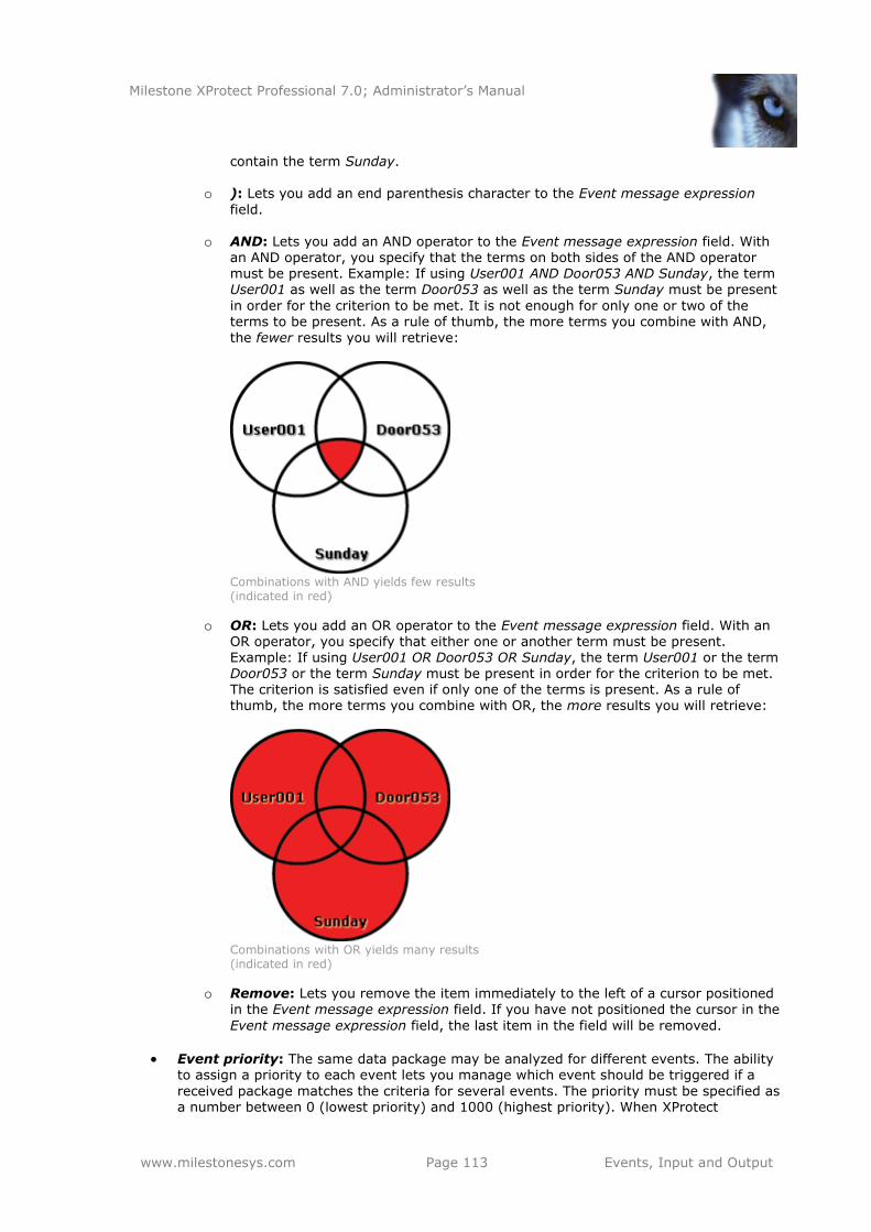
Milestone XProtect Professional 7.0; Administrator’s Manual
www.milestonesys.com Page 113 Events, Input and Output
contain the term Sunday.
o ): Lets you add an end parenthesis character to the Event message expression
field.
o AND: Lets you add an AND operator to the Event message expression field. With an AND operator, you specify that the terms on both sides of the AND operator must be present. Example: If using User001 AND Door053 AND Sunday, the term User001 as well as the term Door053 as well as the term Sunday must be present
in order for the criterion to be met. It is not enough for only one or two of the terms to be present. As a rule of thumb, the more terms you combine with AND,
the fewer results you will retrieve:
Combinations with AND yields few results (indicated in red)
o OR: Lets you add an OR operator to the Event message expression field. With an OR operator, you specify that either one or another term must be present. Example: If using User001 OR Door053 OR Sunday, the term User001 or the term Door053 or the term Sunday must be present in order for the criterion to be met. The criterion is satisfied even if only one of the terms is present. As a rule of thumb, the more terms you combine with OR, the more results you will retrieve:
Combinations with OR yields many results (indicated in red)
o Remove: Lets you remove the item immediately to the left of a cursor positioned
in the Event message expression field. If you have not positioned the cursor in the
Event message expression field, the last item in the field will be removed.
Event priority: The same data package may be analyzed for different events. The ability to assign a priority to each event lets you manage which event should be triggered if a
received package matches the criteria for several events. The priority must be specified as a number between 0 (lowest priority) and 1000 (highest priority). When XProtect
Milestone XProtect Professional 7.0; Administrator’s Manual
www.milestonesys.com Page 114 Events, Input and Output
Professional receives a TCP and/or UDP package, analysis of the packet will start with analysis for the event with the highest priority. This way, when a package matches the criteria for several events, only the event with the highest priority will be triggered. If a
package matches the criteria for several events with an identical priority, for example two events with a priority of 999, all events with the priority in question will be triggered.
Event protocol: Lets you select which protocol XProtect Professional should listen for in
order to detect the event:
o Any: Listen for, and analyze, packages using TCP as well as UDP protocol.
o TCP: Listen for, and analyze, packages using TCP protocol only.
o UDP: Listen for, and analyze, packages using UDP protocol only.
Event rule type: Lets you select how particular XProtect Professional should be when analyzing received data packages:
o Search: In order for the event to occur, the received package must contain the message specified in the Event message expression field, but may also have more content. Example: If you have specified that the received package should contain the terms "User001" and "Door053", the event will be triggered if the received package contains the terms "User001" and "Door053" and "Sunday" since your two required terms are contained in the received package.
o Match: In order for the event to occur, the received package must contain exactly the message specified in the Event message expression field, and nothing else.
Send e-mail if this event occurs: Only available if e-mail notification (see page 103) is
enabled. Select if XProtect Professional should automatically send an e-mail when the event occurs. Recipients are defined as part of the e-mail notification configuration. When using e-mail notifications, also bear in mind individual cameras' scheduling (see page 100).
Attach image from camera: Only available if e-mail notification is enabled. Select to
include an image—recorded at the time the event is triggered—in the e-mail notification, then select the required camera in the list next to the check box.
Send SMS if this event occurs: Only available if SMS (mobile phone text message)
notification (see page 105) is enabled. Select if XProtect Professional should automatically
send an SMS when the event occurs. Recipients are defined as part of the SMS notification configuration. When using SMS notifications, also bear in mind individual cameras' scheduling (see page 100).
Delete: Lets you delete a selected event.
Add: Lets you add a new event. When the Generic Events node is selected, clicking Add
will add a new generic event. When a specific generic event is selected, clicking Add will add a timer event (see page 116) to the selected generic event.
Test a Generic Event
Once you have added a generic event, a quick and easy way to test your generic event is to first set up an event notification and then use Telnet to send a small amount of data which will trigger the generic event and in turn the event notification.
What is Telnet? Telnet is a terminal emulation program used on TCP/IP networks. With Telnet, you can connect to a server from a computer on the network, and execute commands through Telnet as if you were entering them directly on the server. Windows includes a client for use with Telnet.
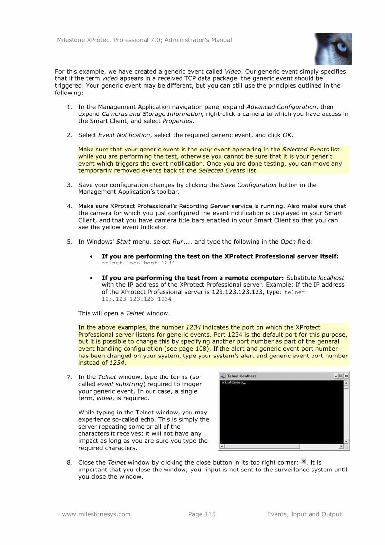
Milestone XProtect Professional 7.0; Administrator’s Manual
www.milestonesys.com Page 115 Events, Input and Output
For this example, we have created a generic event called Video. Our generic event simply specifies that if the term video appears in a received TCP data package, the generic event should be triggered. Your generic event may be different, but you can still use the principles outlined in the
following:
1. In the Management Application navigation pane, expand Advanced Configuration, then expand Cameras and Storage Information, right-click a camera to which you have access in the Smart Client, and select Properties.
2. Select Event Notification, select the required generic event, and click OK.
Make sure that your generic event is the only event appearing in the Selected Events list while you are performing the test, otherwise you cannot be sure that it is your generic event which triggers the event notification. Once you are done testing, you can move any temporarily removed events back to the Selected Events list.
3. Save your configuration changes by clicking the Save Configuration button in the Management Application’s toolbar.
4. Make sure XProtect Professional’s Recording Server service is running. Also make sure that the camera for which you just configured the event notification is displayed in your Smart Client, and that you have camera title bars enabled in your Smart Client so that you can see the yellow event indicator.
5. In Windows' Start menu, select Run..., and type the following in the Open field:
If you are performing the test on the XProtect Professional server itself: telnet localhost 1234
If you are performing the test from a remote computer: Substitute localhost with the IP address of the XProtect Professional server. Example: If the IP address of the XProtect Professional server is 123.123.123.123, type: telnet 123.123.123.123 1234
This will open a Telnet window.
In the above examples, the number 1234 indicates the port on which the XProtect Professional server listens for generic events. Port 1234 is the default port for this purpose, but it is possible to change this by specifying another port number as part of the general
event handling configuration (see page 108). If the alert and generic event port number has been changed on your system, type your system’s alert and generic event port number instead of 1234.
7. In the Telnet window, type the terms (so-
called event substring) required to trigger your generic event. In our case, a single term, video, is required.
While typing in the Telnet window, you may experience so-called echo. This is simply the server repeating some or all of the characters it receives; it will not have any impact as long as you are sure you type the
required characters.
8. Close the Telnet window by clicking the close button in its top right corner: . It is
important that you close the window; your input is not sent to the surveillance system until you close the window.
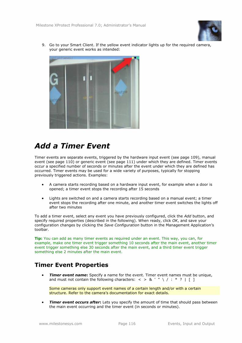
Milestone XProtect Professional 7.0; Administrator’s Manual
www.milestonesys.com Page 116 Events, Input and Output
9. Go to your Smart Client. If the yellow event indicator lights up for the required camera, your generic event works as intended:
Add a Timer Event
Timer events are separate events, triggered by the hardware input event (see page 109), manual event (see page 110) or generic event (see page 111) under which they are defined. Timer events occur a specified number of seconds or minutes after the event under which they are defined has occurred. Timer events may be used for a wide variety of purposes, typically for stopping previously triggered actions. Examples:
A camera starts recording based on a hardware input event, for example when a door is
opened; a timer event stops the recording after 15 seconds
Lights are switched on and a camera starts recording based on a manual event; a timer
event stops the recording after one minute, and another timer event switches the lights off after two minutes
To add a timer event, select any event you have previously configured, click the Add button, and
specify required properties (described in the following). When ready, click OK, and save your
configuration changes by clicking the Save Configuration button in the Management Application’s toolbar. Tip: You can add as many timer events as required under an event. This way, you can, for example, make one timer event trigger something 10 seconds after the main event, another timer event trigger something else 30 seconds after the main event, and a third timer event trigger something else 2 minutes after the main event.
Timer Event Properties
Timer event name: Specify a name for the event. Timer event names must be unique, and must not contain the following characters: < > & ' " \ / : * ? | [ ]
Some cameras only support event names of a certain length and/or with a certain structure. Refer to the camera’s documentation for exact details.
Timer event occurs after: Lets you specify the amount of time that should pass between
the main event occurring and the timer event (in seconds or minutes).
Milestone XProtect Professional 7.0; Administrator’s Manual
www.milestonesys.com Page 117 Events, Input and Output
Add a Hardware Output
With hardware output, you can add external output units, such as lights, sirens, door openers, etc.,
to your XProtect Professional system. Once added, output can be activated automatically by events (see page 107) or detected motion, or manually by users of clients (see page 151). Before you specify output, verify that sensor operation is recognized by the hardware device with which you are going to use the output. Most hardware devices are capable of showing this in their configuration interfaces, or via CGI script commands. Also check the release notes to verify that
output-controlled operation is supported for the hardware device and firmware used.
To add a hardware output event, do the following:
1. In the Management Application’s navigation pane, expand Advanced Configuration, then expand Events and Output. Right-click Hardware Output and select Add New Output.
2. In the Hardware Output Properties window’s list of hardware devices, select the required hardware device, and click the Add button below the list.
3. Specify required properties (described in the following).
4. Click OK.
5. Save your configuration changes by clicking the Save Configuration button in the
Management Application’s toolbar. For information about how to configure automatic activation of hardware output when events occur, see Configure Hardware Output on Event (see page 118).
You configure output for manual activation in clients as well as for automatic activation on detected motion individually for each camera (see page 73).
Hardware Output Properties
Output name: Specify a name for the event. If you are going to make the hardware output available for manual activation in clients, this is the name that client users will see.
Hardware output names must be unique, and must not contain the following characters: <
> & ' " \ / : * ? | [ ]
Some hardware devices only support hardware output names of a certain length and/or with a certain structure. Refer to the hardware device’s documentation for exact details.
Output connected to: Lets you select which of the hardware device’s output ports the output is connected to. Many hardware devices only have a single output port; in that case simply select Output 1.
Keep output for: Lets you specify the amount of time for which the output should be
applied. Specify the required amount of time in either 1/10 seconds or seconds.
Some hardware devices are only able to apply output for a relatively short time, for example for up to five seconds. Refer to the documentation for the hardware device in
question for exact information. Tip: To verify that your hardware output works, click the Test Output button.
Milestone XProtect Professional 7.0; Administrator’s Manual
www.milestonesys.com Page 118 Events, Input and Output
Configure Hardware Output on Event
Once you have added hardware output (see page 117), such as lights, sirens, door openers, etc.,
you can associate the hardware output with events (see page 107). This way, particular hardware output can be activated automatically when events occur. Example: When a door is opened (hardware input event), lights are switched on (hardware output). When making the associations, you can select between all output and events defined on your XProtect Professional server; you are not limited to selecting output or events defined on particular
hardware devices.
1. In the Management Application’s navigation pane, expand Advanced Configuration, then
expand Events and Output. Right-click Output Control on Event and select Properties.
2. In the Event column, select the required event.
3. In the Output column, select the hardware output you want to be activated by the event.
4. Click OK.
5. Save your configuration changes by clicking the Save Configuration button in the Management Application’s toolbar.
You can use a single event for activating more than one output.
You cannot delete associations, but you can change your selections or select None in both columns as required. Tip: If you have not yet defined any suitable event or output, you can quickly do it: Use the
Configure events list and/or Configure Output... button, located below the list of associations.
Milestone XProtect Professional 7.0; Administrator’s Manual
www.milestonesys.com Page 119 Services
Services
The following services are all automatically installed on the XProtect Professional server:
Milestone Recording Server service: A vital part of the surveillance system; video streams are only transferred to XProtect Professional while the Recording Server service is running.
Milestone Image Server service: Provides access to the surveillance system for users
logging in with a Remote Client or a Smart Client. If the PDA Server front end is installed, the Image Server service also handles access for PDA Client users. Read more about the clients on page 151.
Milestone Image Import service: Used for fetching pre- and post-alarm images, and storing the fetched images in camera databases. Pre- and post-alarm images is a feature available for selected cameras only; it enables sending of images from immediately before an event took place from the camera to the surveillance system via e-mail. Pre- and post-
alarm images should not be confused with XProtect Professional’s own pre- and post-recording feature (see page 70).
Milestone Log Check service: Performs integrity checks on XProtect Professional log
files. For more information about logging, see page 128.
The services by default run transparently in the background on the XProtect Professional server.
Start and Stop Services
On an XProtect Professional server, four services by default run in the background. If required, you can start and stop each service separately:
1. In the Management Application’s Navigation pane, expand Advanced Configuration and
select Services. This will display the status of each service.
2. You can now stop each service by clicking the Stop button. When a service is stopped, the button changes to Start, allowing you to start the service again when required.
Tip: Occasionally, you may want to stop a service and start it again immediately after. The Restart button allows you to do just that with a single click.
Milestone XProtect Professional 7.0; Administrator’s Manual
www.milestonesys.com Page 120 Client Access to Surveillance System
Client Access to Surveillance System
You can configure clients' access the XProtect Professional server in two ways: Through a wizard or through Advanced Configuration.
Wizard-driven Configuration
Guided configuration through a wizard lets you quickly specify how clients access the server as well as which users should be able to use clients. See Configure User Access Wizard on page 46. When using the wizard, all users you add will have access to all cameras, including any new cameras added at a later stage. If this is not acceptable, specify access settings, users and user
rights separately; see the following.
Advanced Configuration
In previous versions of XProtect Professional, this was known as Image Server administration,
since technically it is the Image Server service (see page 119) which handles clients' access to the surveillance system.
1. In the Management Application’s navigation pane, expand Advanced Configuration, right-click Server Access and select Properties.
2. Specify required properties for Server Access, Local IP Ranges, and Language Support & XML Encoding. The properties are described on the following pages. When ready, click OK.
3. Save your configuration changes by clicking the Save Configuration button in the Management Application’s toolbar.
When using this option, you configure client users separately from clients' access; see Add Basic Users on page 122, Add Windows Users on page 123, Add User Groups on page 124, and Configure
User & Group Rights on page 124.
Server Access
Server name: Name of the XProtect Professional server as it will appear in clients. Client users with rights to configure their clients will see the name of the server when they create views in their clients.
Local port: Port number to use for communication between clients and the surveillance server. The default port number is 80; you can change the port number if port 80 is used for other purposes in your organization.
Enable internet access: Select the check box if the server should be accessible from the
internet through a router or firewall. If selecting this option, also specify the public (―outside‖) IP address and port number in the following fields. When using public access, the router or firewall used must be configured so requests sent to the public IP address and port are forwarded to the local (―inside‖) IP address and port of the XProtect Professional
server.
Milestone XProtect Professional 7.0; Administrator’s Manual
www.milestonesys.com Page 121 Client Access to Surveillance System
Internet address: Lets you specify a public IP address or hostname for use when the
XProtect Professional server should be available from the internet.
Internet port: Lets you specify a port number for use when the XProtect Professional
should be available from the internet. The default port number is 80; you can change the port number if port 80 is used for other purposes in your organization.
Max. number of clients: You can limit the number of clients allowed to connect at the same time. Depending on your XProtect Professional configuration and the performance of
the hardware and network used, limiting the number of simultaneously connected clients may help reduce server load. If more than the allowed number of simultaneously
connected clients attempt to log in, only the allowed number of clients will be allowed access. Any clients in excess of the allowed number will receive an error message when attempting to log in. By default, a maximum of ten simultaneously connected clients are allowed. To specify a different maximum number, simply overwrite the value.
Tip: To allow an unlimited number of simultaneously connected access clients, type 0 (zero) in the Max. number of clients field. A four-minute session timeout period applies for client sessions on XProtect Professional. In many cases, client users may not notice this at all. However, the session timeout period will be very evident if you set the Max. number of clients value to 1. When that is the case,
and the single allowed client user logs out, four minutes must pass before it will be possible to log in again.
Local IP Ranges
You can specify IP address ranges which XProtect Professional should recognize as coming from a local network. This can be relevant if different subnets are used across you local network.
1. Click the Add button.
2. In the Start Address column, specify the first IP address in the required range.
3. In the End Address column, specify the last IP address in the required range.
Tip: If required, an IP address range may include only one IP address (example:
192.168.10.1-192.168.10.1).
4. Repeat if other local IP address ranges are required.
Language Support & XML Encoding
You can select the language/character set used by the XProtect Professional server and clients.
Language: Select required language/character set. Example: If the surveillance server
runs a Japanese version of Windows, select Japanese. Provided access clients also use a Japanese version of Windows, this will ensure that the correct language and character encoding is used in clients' communication with the server.
Milestone XProtect Professional 7.0; Administrator’s Manual
www.milestonesys.com Page 122 Users
Users
To get an overview of your XProtect Professional system’s users, expand Advanced Configuration in the Management Application’s navigation pane, then expand Users.
The term users primarily refers to users who are able to connect to the surveillance system through their clients (see page 151). You can configure such users in two ways:
As basic users, authenticated by a user name/password combination.
As Windows users, authenticated based on their Windows login You can add both types of users through the Configure User Access wizard (see page 46) or
individually (see Add Basic Users in the following and Add Windows Users on page 123).
By grouping users, you can specify rights (see page 124) for all users within a group in one go.
If you have many users performing similar tasks, this can save you significant amounts of work. User groups are logical groups created and used for practical purposes in the Management Application only. They are not in any way connected with user groups from central directory services such as, for example, Active Directory®. If you want to use groups, make sure you add
groups (see page 124) before you add users: You cannot add existing users to groups.
Finally, the administrator is also listed under Users. If required, this lets you configure
password protection for the Management Application (see page 24).
Wizard-driven Configuration
The Configure User Access Wizard (see page 46) helps you quickly configure clients' access to the XProtect Professional server as well as which users should be able to use clients.
When using the wizard, all users you add will have access all to cameras, including any new cameras added at a later stage. If this is not acceptable, specify access settings, users and user rights separately. Also note that you cannot add users to groups through the wizard.
Advanced Configuration
Add Basic Users
When adding a basic user, you create a dedicated surveillance system user account with basic user name and password authentication for the individual user. Note that adding the user as a Windows user (see page 123) will provide better security. If you want to include users in groups, make sure you add required groups (see page 124) before you add users: You cannot add existing users to groups.
1. In the Management Application’s navigation pane, expand Advanced Configuration, right-click Users, and select Add New Basic User.
2. Specify a user name. User names must be unique, and must not contain the following characters: < > & ' " \ / : * ? | [ ]
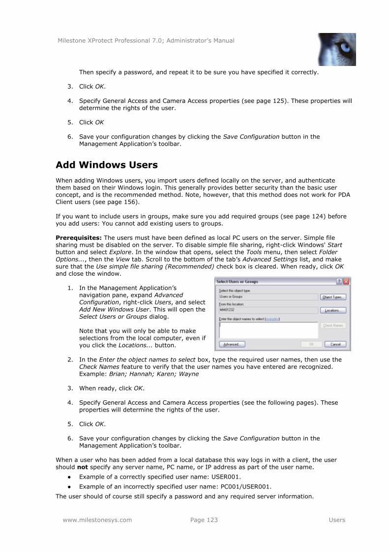
Milestone XProtect Professional 7.0; Administrator’s Manual
www.milestonesys.com Page 123 Users
Then specify a password, and repeat it to be sure you have specified it correctly.
3. Click OK.
4. Specify General Access and Camera Access properties (see page 125). These properties will
determine the rights of the user.
5. Click OK
6. Save your configuration changes by clicking the Save Configuration button in the Management Application’s toolbar.
Add Windows Users
When adding Windows users, you import users defined locally on the server, and authenticate them based on their Windows login. This generally provides better security than the basic user concept, and is the recommended method. Note, however, that this method does not work for PDA Client users (see page 156).
If you want to include users in groups, make sure you add required groups (see page 124) before you add users: You cannot add existing users to groups. Prerequisites: The users must have been defined as local PC users on the server. Simple file sharing must be disabled on the server. To disable simple file sharing, right-click Windows' Start
button and select Explore. In the window that opens, select the Tools menu, then select Folder
Options..., then the View tab. Scroll to the bottom of the tab’s Advanced Settings list, and make sure that the Use simple file sharing (Recommended) check box is cleared. When ready, click OK and close the window.
1. In the Management Application’s navigation pane, expand Advanced Configuration, right-click Users, and select
Add New Windows User. This will open the Select Users or Groups dialog. Note that you will only be able to make selections from the local computer, even if you click the Locations... button.
2. In the Enter the object names to select box, type the required user names, then use the
Check Names feature to verify that the user names you have entered are recognized. Example: Brian; Hannah; Karen; Wayne
3. When ready, click OK.
4. Specify General Access and Camera Access properties (see the following pages). These properties will determine the rights of the user.
5. Click OK.
6. Save your configuration changes by clicking the Save Configuration button in the Management Application’s toolbar.
When a user who has been added from a local database this way logs in with a client, the user should not specify any server name, PC name, or IP address as part of the user name.
● Example of a correctly specified user name: USER001.
● Example of an incorrectly specified user name: PC001/USER001.
The user should of course still specify a password and any required server information.
Milestone XProtect Professional 7.0; Administrator’s Manual
www.milestonesys.com Page 124 Users
Add User Groups
User groups are logical groups created and used for practical purposes in the Management Application only. They are not in any way connected with user groups from central directory
services such as, for example, Active Directory®. By grouping users, you can specify rights for all users within a group in one go. If you have many users performing similar tasks, this can save you significant amounts of work. Make sure you add groups before you add users: You cannot add existing users to groups.
1. In the Management Application’s navigation pane, expand Advanced Configuration, right-click Users, and select Add New User Group.
2. Specify a name for the group. Group names must be unique, and must not contain the following characters: < > & ' " \ / : * ? | [ ]
3. Click OK.
4. Specify General Access and Camera Access properties (see the following pages). These properties will determine the rights of the group’s future members.
5. Click OK
6. Save your configuration changes by clicking the Save Configuration button in the Management Application’s toolbar.
7. Now you can add users to the group: In the navigation pane, right-click the group you just
created, and add Basic Users (see page 122) or Windows Users (see page 123) as required.
Configure User and Group Rights
User/group rights are configured during the process of adding users/groups, see Add Basic Users, Add Windows Users and Add User Groups in the previous. Note that you can also add basic and Windows users through the Configure User Access wizard (see page 46). However, when using the wizard all users you add will have access all to cameras,
including any new cameras added at a later stage.
If you at a later stage want to edit the rights of a user or group:
1. In the Management Application’s navigation pane, expand Advanced Configuration, expand Users, right-click the required user or group, and select Properties.
2. Edit General Access and Camera Access properties (see the following). These properties will determine the rights of the user/group.
3. Click OK
4. Save your configuration changes by clicking the Save Configuration button in the
Management Application’s toolbar.
Milestone XProtect Professional 7.0; Administrator’s Manual
www.milestonesys.com Page 125 Users
User and Group Properties
User Information
User name: Only editable if the selected user is of the type basic user. Lets you edit the user name. User names must be unique, and must not contain the following characters: < > & ' " \ / : * ? | [ ]
Password: Only editable if the selected user is of the type basic user. Lets you edit the
password. Remember to repeat the password to be sure you have specified it correctly.
User type: Non-editable field, displaying whether the selected user is of the type basic
user or Windows user.
Group Properties
Group name: Lets you edit the group name. Group names must be unique, and must not
contain the following characters: < > & ' " \ / : * ? | [ ]
General Access
When adding or editing basic users, Windows users or groups, specify general access settings:
Live: Ability to access the Live tab in the Smart Client and Remote Client.
Playback: Ability to access the Playback tab in the Smart Client and Remote Client.
Setup: Ability to access the Setup tab in the Smart Client and Remote Client.
Edit shared views: Ability to create and edit views in shared groups in the Smart Client
and Remote Client. Views placed in shared groups can be accessed by every user. If a user/group does not have this right, shared groups will be protected, indicated by a padlock icon in the Smart Client and Remote Client.
Views created in a Smart Client can only be shared with other Smart Client users. Views
created in a Remote Client can only be shared with other Remote Client users. It is not possible to share views across the two types of client.
Edit private views: Ability to create and edit views in private groups in the Smart Client
and Remote Client. Views placed in private groups can only be accessed by the user who created them. If a user/group does not have this right, private groups will be protected, indicated by a padlock icon in the Smart Client and Remote Client. Denying users the right to create their own views may make sense in some cases; for example in order to limit bandwidth use.
For more information about shared and private views, see the separate Smart Client and Remote
Client documentation
Tip: By clearing the Live, Playback and Setup check boxes you can effectively disable the user’s/group’s ability to use the Smart Client and Remote Client. You can use this as a temporary alternative to deleting the user/group, for example while the user is on vacation.
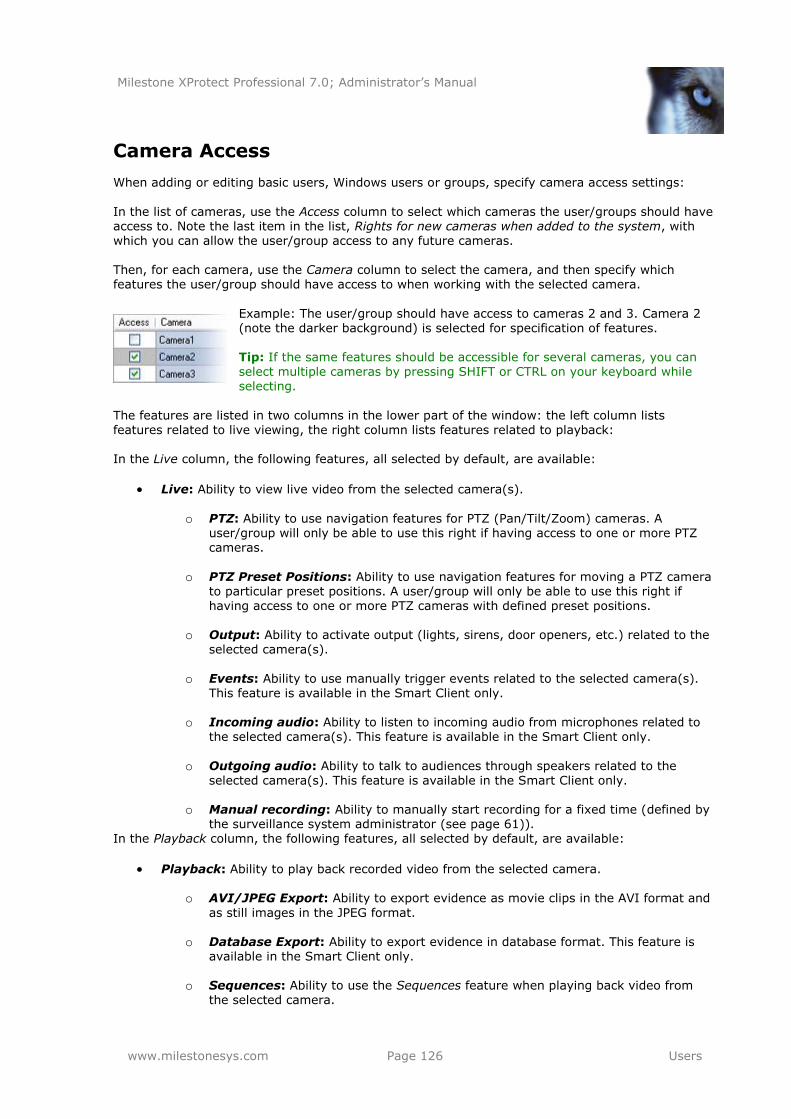
Milestone XProtect Professional 7.0; Administrator’s Manual
www.milestonesys.com Page 126 Users
Camera Access
When adding or editing basic users, Windows users or groups, specify camera access settings:
In the list of cameras, use the Access column to select which cameras the user/groups should have access to. Note the last item in the list, Rights for new cameras when added to the system, with which you can allow the user/group access to any future cameras. Then, for each camera, use the Camera column to select the camera, and then specify which features the user/group should have access to when working with the selected camera.
Example: The user/group should have access to cameras 2 and 3. Camera 2 (note the darker background) is selected for specification of features. Tip: If the same features should be accessible for several cameras, you can select multiple cameras by pressing SHIFT or CTRL on your keyboard while selecting.
The features are listed in two columns in the lower part of the window: the left column lists features related to live viewing, the right column lists features related to playback: In the Live column, the following features, all selected by default, are available:
Live: Ability to view live video from the selected camera(s).
o PTZ: Ability to use navigation features for PTZ (Pan/Tilt/Zoom) cameras. A
user/group will only be able to use this right if having access to one or more PTZ cameras.
o PTZ Preset Positions: Ability to use navigation features for moving a PTZ camera
to particular preset positions. A user/group will only be able to use this right if having access to one or more PTZ cameras with defined preset positions.
o Output: Ability to activate output (lights, sirens, door openers, etc.) related to the selected camera(s).
o Events: Ability to use manually trigger events related to the selected camera(s).
This feature is available in the Smart Client only.
o Incoming audio: Ability to listen to incoming audio from microphones related to the selected camera(s). This feature is available in the Smart Client only.
o Outgoing audio: Ability to talk to audiences through speakers related to the
selected camera(s). This feature is available in the Smart Client only.
o Manual recording: Ability to manually start recording for a fixed time (defined by the surveillance system administrator (see page 61)).
In the Playback column, the following features, all selected by default, are available:
Playback: Ability to play back recorded video from the selected camera.
o AVI/JPEG Export: Ability to export evidence as movie clips in the AVI format and
as still images in the JPEG format.
o Database Export: Ability to export evidence in database format. This feature is
available in the Smart Client only.
o Sequences: Ability to use the Sequences feature when playing back video from the selected camera.
Milestone XProtect Professional 7.0; Administrator’s Manual
www.milestonesys.com Page 127 Users
o Smart Search: Ability to use the smart search feature, with which users can search for motion in one or more selected areas of images from the selected camera. This feature is available in the Smart Client only.
o Audio: Ability to listen to recorded audio from microphones related to the selected
camera(s). Why can I not select certain features? Typically because the selected camera does not support the features. For example, you can only select PTZ-related features if the camera is a PTZ camera.
Also, some of the features depend on the user’s/group’s General Access properties (see page 125): For example, in order have access to PTZ or output features, the user/group must have access to
viewing live video; in order to use AVI/JPEG export, the user/group must have access to playing back recorded video. Why are some feature check boxes filled with squares? Square-filled check boxes can appear in the lower part of the window if you have selected several cameras and a feature applies for
some but not all of the cameras. Example: For camera A you have selected that use of the Events is allowed; for camera B it is not allowed. If you select both camera A and camera B in the list, the Events check box in the lower part of the window will be square-filled. Another example: Camera C is a PTZ camera for which you have allowed the PTZ preset positions feature; camera D is not a PTZ camera. If you select both camera C and camera D in the list, the PTZ preset positions check box will be square-filled.
Milestone XProtect Professional 7.0; Administrator’s Manual
www.milestonesys.com Page 128 Logging
Logging
XProtect Professional is able to generate various logs:
Management Application log files. These files log activity in the Management Application. A new log file is created for each day the Management Application is used. You cannot disable this type of logging. Management Application log files are named according to the structure AdminYYYYMMDD.log, for example Admin20091231.log.
Recording Server service log files. These files log Recording Server service activity (see page 119). A new log file is created for each day the service is used. You cannot disable this type of logging. Recording Server service log files are named according to the structure RecordingServerYYYYMMDD.log, for example RecordingServer20091231.log.
Image Server service log files. These files log activity on the Image Server service (see page 119). A new log file is created for each day the service is used. You cannot disable this type of logging. Image Server service log files are named according to the structure
ISLog_YYYYMMDD.log, for example ISLog_20091231.log.
Image Import service log files. These files log activity regarding the Image Import service, when this service is used for fetching pre-alarm images, and storing the fetched
images in camera databases. Pre-alarm images is a feature available for selected cameras
only; it enables sending of images from immediately before an event took place from the camera to the surveillance system via e-mail. A new log file is created for each day the service is used. You cannot disable this type of logging. Image Import service log files are named according to the structure ImageImportLog_YYYMMDD.log, for example ImageImportLog20091231.log.
Event log files. These files log information about registered events (see page 107). A new log file is created for each day on which events occur. You cannot disable this type of logging. Event log files should be viewed using the Smart Client (use the Playback tab’s Alerts section) or the Viewer (use the Alarm Overview control panel).
Audit log files: These files log Remote Client and Smart Client user activity provided audit logging is enabled. A new log file is created for each day with audit logging enabled and client user activity. Audit log files are named according to the structure
is_auditYYYMMDD.log, for example is_audit20091231.log. The _is prefix is due to the fact that the audit log files are generated by the Image Server service.
Viewer export log files: These files log activity regarding database export from the
Viewer (not from the Smart Client). A new log file is created for each day on which export is performed from the Viewer. Exported databases as well as the export log files are by default placed in an Exported Images folder on the desktop of the computer on which the export was performed. Note that the export location may be changed as part of the export process. Viewer export log files are named according to the structure ExportYYYMMDD.log, for example Export20091231.log. Note that database exports may be encrypted and/or compressed, in which case Viewer export log files are also encrypted/compressed and
further file extensions, such as .mzi or .men, may appear in Viewer export log file names. All log files are by default placed in the appropriate All Users folder for the operating system used,
for example C:\ProgramData\Milestone if running Windows Vista. By default, they are stored there for seven days. Note, however, that log file locations as well as the number of days to store the logs can be changed as part of the logging configuration.
Most log files generated by XProtect Professional use a shared structure complying with the W3C Extended Log File Format. Each log file consists of a header and a number of log lines:
Milestone XProtect Professional 7.0; Administrator’s Manual
www.milestonesys.com Page 129 Logging
The header outlines the information contained in the log lines.
The log lines consist of two main parts: the log information itself as well as an encrypted part. The encrypted part makes it possible—through decryption and comparison—to assert
that a log file has not been tampered with.
Configure System, Event, and Audit Logging
1. In the Management Application’s Navigation pane, expand Advanced Configuration, right-click Logs and select Properties.
2. Specify required properties (see the following) for:
General system logs (Management Application log, Recording Server service log, Image Server service log, Image Import service log)
The event log
The audit log
Note that only audit logging can be disabled/enabled by administrators; all other logs are compulsory. When ready, click OK.
3. Save your configuration changes by clicking the Save Configuration button in the
Management Application’s toolbar.
Log Properties
When you configure logging, you can define the following properties: Logs (that is Management Application log, Recording Server service log, Image Server service log, Image Import service log)
Path: These system log files are by default placed in the appropriate All Users folder for the operating system used, for example C:\ProgramData\Milestone if running Windows
Vista. To specify another location for your log files, type the path to the required folder in the Path field, or click the browse button next to the field to browse to the required folder.
Days to log: A new log file is created each day the Management Application and/or the services are used. A log file older than the number of days specified in the field is automatically deleted. By default, the log file will be stored for seven days. To specify another number of days (max. 9999), simply overwrite the value in the field. The current
day’s activity is always logged, even with a value of 0 in the field. Therefore, if you specify 0, you will log current day’s activity; if you specify 1, you will keep one day plus the current day’s activity, and so on.
Event Log
Path: Event log files are by default placed in the appropriate All Users folder for the
operating system used, for example C:\ProgramData\Milestone if running Windows Vista. To specify another location for your event log files, type the path to the required folder in the Path field, or click the browse button next to the field to browse to the required folder.
Days to log: A new log file is created for each day on which events occur. A log file older than the number of days specified in the field is automatically deleted. By default, the log file will be stored for seven days. To specify another number of days (max. 9999), simply
Milestone XProtect Professional 7.0; Administrator’s Manual
www.milestonesys.com Page 130 Logging
overwrite the value in the field. The current day’s activity is always logged, even with a value of 0 in the field. Therefore, if you specify 0, you will log current day’s activity; if you specify 1, you will keep one day plus the current day’s activity, and so on.
Audit Log
Enable audit logging: Audit logging is the only type of XProtect Professional logging
which is not compulsory. Select/clear the check box to enable/disable audit logging.
Path: Audit log files are by default placed in the appropriate All Users folder for the operating system used, for example C:\ProgramData\Milestone if running Windows Vista.
To specify another location for your audit log files, type the path to the required folder in the Path field, or click the browse button next to the field to browse to the required folder.
Days to log: A new log file is created for each day with audit logging enabled and client
user activity. A log file older than the number of days specified in the field is automatically deleted. By default, the log file will be stored for seven days. To specify another number of days (max. 9999), simply overwrite the value in the field. The current day’s activity is always logged (provided audit logging is enabled and there is user activity). Therefore, if you specify 1, you will keep one day plus the current day’s activity. Note that if you specify 0 (zero), audit log files will be kept indefinitely (disk space permitting).
Minimum logging interval: Minimum number of seconds between logged events. Specifying a high number of seconds between logged events may help reduce the size of the audit log. Default is 60 seconds.
In sequence timespan: Number of seconds to pass for viewed images to be considered to be within the same sequence. Specifying a high number of seconds may help limit the number of viewed sequences logged, and thus reduce the size of the audit log. Default is ten seconds.
Log Integrity Checks
All log files, except Management Application log files, are subjected to an integrity check once every 24 hours. The integrity check is performed by XProtect Professional’s Log Check service. The result of the integrity check is automatically written to a file named according to the structure
LogCheck_YYYYMMDD.log, for example LogCheck_20091231.log. Like the log files themselves, the log check files are by default placed in the appropriate All Users folder for the operating system
used, for example C:\ProgramData\Milestone if running Windows Vista. Any inconsistencies will be reported in the form of error messages written in the log check file. Possible error messages (other, non-error, messages may also appear in the log check file):
Log integrity information was not found. Log integrity can't be guaranteed.
The log file could not be checked for integrity.
Log information does not match integrity information. Log integrity can't be
guaranteed. The log file exists, but does not contain the expected information. Thus, log integrity cannot be guaranteed.
[Log file name] not found
The log file was not present.
[Log file name] is empty
The log file was present, but empty.

Milestone XProtect Professional 7.0; Administrator’s Manual
www.milestonesys.com Page 131 Logging
Last line changed/removed in [log file name]
The last line of the log file did not match validation criteria.
Encrypted data missing in [log file name] near line [#]
The encrypted part of the log line in question was not present.
Inconsistency found in [log file name] near line [#] The log line does not match the encrypted part.
Inconsistency found in [log file name] at beginning of log file
The log file header is not correct. This situation is most likely to occur if a user has attempted to delete the beginning of a log file.

Milestone XProtect Professional 7.0; Administrator’s Manual
www.milestonesys.com Page 132 Central
Central
Central settings are relevant only if you are using the XProtect Central add-on product in connection with XProtect Professional.
The XProtect Central Settings lets you specify the login settings required for an XProtect Central server to access the surveillance system in order to retrieve status information and alarms.
1. In the Management Application’s Navigation pane, expand Advanced Configuration, right-click Central and select Properties.
2. Enable the use of Central connections by selecting the Enable Milestone XProtect Central check box.
3. Specify required properties:
Enable Milestone XProtect Central connections: Enables the use of XProtect
Central connections, allowing you to specify further properties.
Login Name: Type the name used for the connection between the XProtect
Professional and XProtect Central servers. The name must match the name specified on the XProtect Central server itself. Default name is Name.
Password: Type the password used for the connection between the XProtect
Professional and XProtect Central servers. The password must match the password specified on the XProtect Central server itself. Default password is Pass.
Port: Type the port number to which the XProtect Central server should connect
when accessing the XProtect Professional server. The port number must match the port number specified on the XProtect Central server itself. Default port is 1237.
When ready, click OK.
4. Save your configuration changes by clicking the Save Configuration button in the
Management Application’s toolbar.
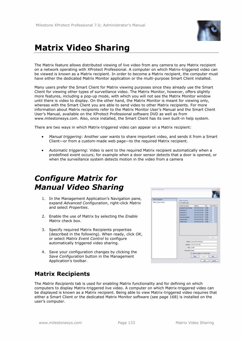
Milestone XProtect Professional 7.0; Administrator’s Manual
www.milestonesys.com Page 133 Matrix Video Sharing
Matrix Video Sharing
The Matrix feature allows distributed viewing of live video from any camera to any Matrix recipient on a network operating with XProtect Professional. A computer on which Matrix-triggered video can
be viewed is known as a Matrix recipient. In order to become a Matrix recipient, the computer must have either the dedicated Matrix Monitor application or the multi-purpose Smart Client installed. Many users prefer the Smart Client for Matrix viewing purposes since they already use the Smart
Client for viewing other types of surveillance video. The Matrix Monitor, however, offers slightly more features, including a pop-up mode, with which you will not see the Matrix Monitor window until there is video to display. On the other hand, the Matrix Monitor is meant for viewing only,
whereas with the Smart Client you are able to send video to other Matrix recipients. For more information about Matrix recipients refer to the Matrix Monitor User’s Manual and the Smart Client User’s Manual, available on the XProtect Professional software DVD as well as from www.milestonesys.com. Also, once installed, the Smart Client has its own built-in help system. There are two ways in which Matrix-triggered video can appear on a Matrix recipient:
Manual triggering: Another user wants to share important video, and sends it from a Smart Client—or from a custom-made web page—to the required Matrix recipient.
Automatic triggering: Video is sent to the required Matrix recipient automatically when a
predefined event occurs; for example when a door sensor detects that a door is opened, or when the surveillance system detects motion in the video from a camera
Configure Matrix for
Manual Video Sharing
1. In the Management Application’s Navigation pane, expand Advanced Configuration, right-click Matrix and select Properties.
2. Enable the use of Matrix by selecting the Enable
Matrix check box.
3. Specify required Matrix Recipients properties (described in the following). When ready, click OK, or select Matrix Event Control to configure automatically triggered video sharing.
4. Save your configuration changes by clicking the
Save Configuration button in the Management Application’s toolbar.
Matrix Recipients
The Matrix Recipients tab is used for enabling Matrix functionality and for defining on which computers to display Matrix-triggered live video. A computer on which Matrix-triggered video can
be displayed is known as a Matrix recipient. Being able to view Matrix-triggered video requires that either a Smart Client or the dedicated Matrix Monitor software (see page 168) is installed on the user’s computer.

Milestone XProtect Professional 7.0; Administrator’s Manual
www.milestonesys.com Page 134 Matrix Video Sharing
Enable matrix: Select check box to enable Matrix functionality.
[List of Defined Matrix recipients]: Lists any already defined Matrix recipients, that is computers on which Matrix-triggered video can be displayed. To change the properties of
an already defined Matrix recipient, select the required Matrix recipient, then make the changes in the fields below the list, and then click the Update button. To remove a Matrix recipient from the list, select the unwanted Matrix recipient, then click the Delete button.
Delete: Available only when you have selected a Matrix recipient in the list. Clicking the
Delete button will remove the selected Matrix recipient. You will be prompted to confirm the removal.
Name: Name for the Matrix recipient. Used when adding a new Matrix recipient or editing
the properties of an existing one. The name will appear in various day-to-day usage situations; it is therefore a good idea to use a descriptive and unambiguous name. Matrix recipient names must not contain the following characters: < > & ' " \ / : * ? | [ ]
Address: IP address of the Matrix recipient, used when adding a new Matrix recipient or
editing the properties of an existing one.
Port: Lets you specify the port number to be used when sending commands to the Matrix
recipient. Used when adding a new Matrix recipient or editing the properties of an existing one. The Matrix recipient will listen for commands on this port. By default, port 12345 is used; you can of course specify another port number.
Password: Lets you specify the password to be used when communicating with the Matrix
recipient. Used when adding a new Matrix recipient or editing the properties of an existing one.
Matrix recipient is a Smart Client: Select check box if the Matrix recipient in question is
a Smart Client. Matrix-triggered live video may also be displayed in XProtect Professional users' Smart Clients. If a Smart Client is used, distribution of the Matrix-triggered live video takes place slightly differently.
Clear: Removes any content in the Name, Address, and Password fields.
Update: Updates the properties of the selected Matrix recipient with the changes made during editing. Available only if you have edited the properties of an existing Matrix
recipient.
Add: Adds the new Matrix recipient to the list. Available only if you have added properties of a new Matrix recipient in the Name, Address, Port, Password, and possibly Smart Client
fields.
Configure Matrix for Automatic Video Sharing
1. In the Management Application’s Navigation pane, expand Advanced Configuration, right-
click Matrix and select Properties.
2. Enable the use of Matrix by selecting the Enable Matrix check box. Specify required Matrix Recipients properties (described in the previous).
3. Select Matrix Event Control and configure Matrix Event Control properties (described in the following). When ready, click OK.
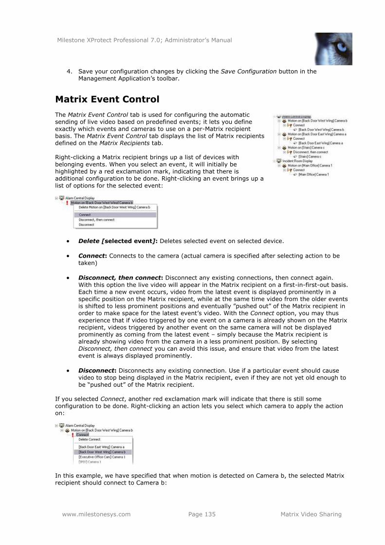
Milestone XProtect Professional 7.0; Administrator’s Manual
www.milestonesys.com Page 135 Matrix Video Sharing
4. Save your configuration changes by clicking the Save Configuration button in the Management Application’s toolbar.
Matrix Event Control
The Matrix Event Control tab is used for configuring the automatic sending of live video based on predefined events; it lets you define exactly which events and cameras to use on a per-Matrix recipient basis. The Matrix Event Control tab displays the list of Matrix recipients defined on the Matrix Recipients tab.
Right-clicking a Matrix recipient brings up a list of devices with
belonging events. When you select an event, it will initially be highlighted by a red exclamation mark, indicating that there is additional configuration to be done. Right-clicking an event brings up a list of options for the selected event:
Delete [selected event]: Deletes selected event on selected device.
Connect: Connects to the camera (actual camera is specified after selecting action to be
taken)
Disconnect, then connect: Disconnect any existing connections, then connect again.
With this option the live video will appear in the Matrix recipient on a first-in-first-out basis. Each time a new event occurs, video from the latest event is displayed prominently in a specific position on the Matrix recipient, while at the same time video from the older events is shifted to less prominent positions and eventually ‖pushed out‖ of the Matrix recipient in order to make space for the latest event’s video. With the Connect option, you may thus
experience that if video triggered by one event on a camera is already shown on the Matrix recipient, videos triggered by another event on the same camera will not be displayed prominently as coming from the latest event – simply because the Matrix recipient is already showing video from the camera in a less prominent position. By selecting
Disconnect, then connect you can avoid this issue, and ensure that video from the latest event is always displayed prominently.
Disconnect: Disconnects any existing connection. Use if a particular event should cause video to stop being displayed in the Matrix recipient, even if they are not yet old enough to be ―pushed out‖ of the Matrix recipient.
If you selected Connect, another red exclamation mark will indicate that there is still some configuration to be done. Right-clicking an action lets you select which camera to apply the action on:
In this example, we have specified that when motion is detected on Camera b, the selected Matrix recipient should connect to Camera b:

Milestone XProtect Professional 7.0; Administrator’s Manual
www.milestonesys.com Page 136 Matrix Video Sharing
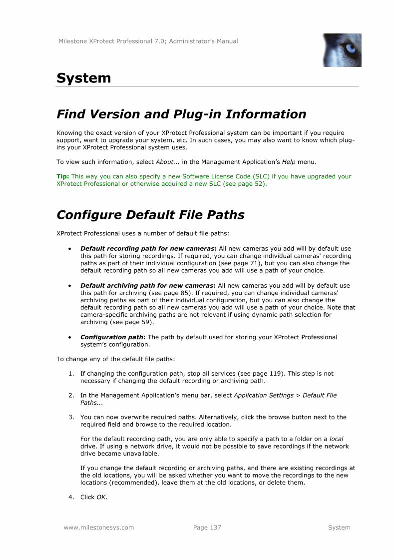
Milestone XProtect Professional 7.0; Administrator’s Manual
www.milestonesys.com Page 137 System
System
Find Version and Plug-in Information
Knowing the exact version of your XProtect Professional system can be important if you require support, want to upgrade your system, etc. In such cases, you may also want to know which plug-ins your XProtect Professional system uses.
To view such information, select About... in the Management Application’s Help menu. Tip: This way you can also specify a new Software License Code (SLC) if you have upgraded your
XProtect Professional or otherwise acquired a new SLC (see page 52).
Configure Default File Paths
XProtect Professional uses a number of default file paths:
Default recording path for new cameras: All new cameras you add will by default use
this path for storing recordings. If required, you can change individual cameras' recording paths as part of their individual configuration (see page 71), but you can also change the default recording path so all new cameras you add will use a path of your choice.
Default archiving path for new cameras: All new cameras you add will by default use
this path for archiving (see page 85). If required, you can change individual cameras' archiving paths as part of their individual configuration, but you can also change the default recording path so all new cameras you add will use a path of your choice. Note that camera-specific archiving paths are not relevant if using dynamic path selection for
archiving (see page 59).
Configuration path: The path by default used for storing your XProtect Professional system’s configuration.
To change any of the default file paths:
1. If changing the configuration path, stop all services (see page 119). This step is not necessary if changing the default recording or archiving path.
2. In the Management Application’s menu bar, select Application Settings > Default File
Paths...
3. You can now overwrite required paths. Alternatively, click the browse button next to the required field and browse to the required location. For the default recording path, you are only able to specify a path to a folder on a local
drive. If using a network drive, it would not be possible to save recordings if the network drive became unavailable.
If you change the default recording or archiving paths, and there are existing recordings at the old locations, you will be asked whether you want to move the recordings to the new locations (recommended), leave them at the old locations, or delete them.
4. Click OK.
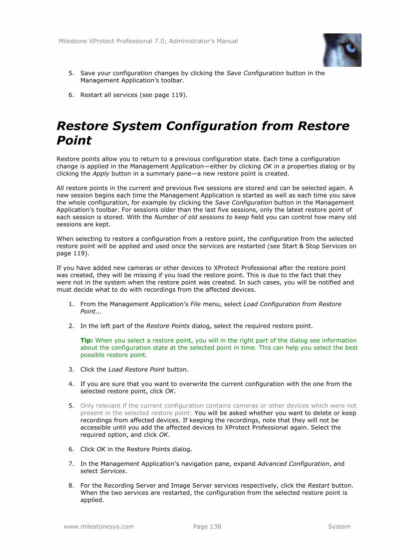
Milestone XProtect Professional 7.0; Administrator’s Manual
www.milestonesys.com Page 138 System
5. Save your configuration changes by clicking the Save Configuration button in the Management Application’s toolbar.
6. Restart all services (see page 119).
Restore System Configuration from Restore Point
Restore points allow you to return to a previous configuration state. Each time a configuration
change is applied in the Management Application—either by clicking OK in a properties dialog or by clicking the Apply button in a summary pane—a new restore point is created. All restore points in the current and previous five sessions are stored and can be selected again. A new session begins each time the Management Application is started as well as each time you save the whole configuration, for example by clicking the Save Configuration button in the Management Application’s toolbar. For sessions older than the last five sessions, only the latest restore point of
each session is stored. With the Number of old sessions to keep field you can control how many old sessions are kept. When selecting to restore a configuration from a restore point, the configuration from the selected restore point will be applied and used once the services are restarted (see Start & Stop Services on
page 119).
If you have added new cameras or other devices to XProtect Professional after the restore point was created, they will be missing if you load the restore point. This is due to the fact that they were not in the system when the restore point was created. In such cases, you will be notified and must decide what to do with recordings from the affected devices.
1. From the Management Application’s File menu, select Load Configuration from Restore
Point...
2. In the left part of the Restore Points dialog, select the required restore point. Tip: When you select a restore point, you will in the right part of the dialog see information about the configuration state at the selected point in time. This can help you select the best
possible restore point.
3. Click the Load Restore Point button.
4. If you are sure that you want to overwrite the current configuration with the one from the
selected restore point, click OK.
5. Only relevant if the current configuration contains cameras or other devices which were not
present in the selected restore point: You will be asked whether you want to delete or keep recordings from affected devices. If keeping the recordings, note that they will not be accessible until you add the affected devices to XProtect Professional again. Select the required option, and click OK.
6. Click OK in the Restore Points dialog.
7. In the Management Application’s navigation pane, expand Advanced Configuration, and
select Services.
8. For the Recording Server and Image Server services respectively, click the Restart button. When the two services are restarted, the configuration from the selected restore point is applied.
Milestone XProtect Professional 7.0; Administrator’s Manual
www.milestonesys.com Page 139 System
Export and Import System Configuration as Backup or Clone
You can export the current configuration of your XProtect Professional system, either as a safety measure in order to have a backup file of your configuration, or a as a clone allowing you to use a similar configuration elsewhere. You are subsequently able to import previously exported configurations.
Export Configuration as Backup
With this option, all relevant XProtect Professional configuration files will be combined into one
single file, which can then be saved at a location specified by you. Note that if there are unsaved changes to your configuration, they will automatically be saved when you export the configuration. If you intend to set up an identical version of your surveillance system elsewhere, do not export your configuration as backup. Instead, export your configuration as a clone (see the following). When you export as a clone, the export takes into account the fact that you will not use the exact
same physical hardware devices even though your new system may otherwise be identical to your existing one.
1. In the Management Application’s File menu, select Export Configuration - Backup.
2. Browse to the location at which you want to store the exported configuration, specify a suitable file name, and click Save.
Export Configuration as Clone
With this option, all relevant XProtect Professional configuration files will be collected and GUIDs (Globally Unique IDentifiers; unique 128-bit numbers used for identifying individual system components, such as cameras) will be marked for later replacement. Why are GUIDs marked for replacement? GUIDs are marked for later replacement because they refer to specific components (cameras, etc.). Even though you wish to use the cloned
configuration for setting up a new similar system using similar types of cameras, the new system would not use the exact same cameras as the cloned system. When the cloned configuration is
later used in a new system, the GUIDs will therefore be replaced with GUIDs representing the specific components of the new system. After GUIDs have been marked for replacement, the configuration files will be combined into one
single file, which can then be saved at a location specified by you. Note that if there are unsaved changes to your configuration, they will automatically be saved when you export the configuration.
1. In the Management Application’s File menu, select Export Configuration - Clone.
2. Browse to the location at which you want to store the exported configuration, specify a suitable file name, and click Save.
Import Previously Exported Configuration
The same import method is used regardless of whether the configuration was exported as a backup or a clone.
1. In the Management Application’s File menu, select Import Configuration.
Milestone XProtect Professional 7.0; Administrator’s Manual
www.milestonesys.com Page 140 System
2. Browse to the location from which you want to import the configuration, select the required configuration file, and click Open.
3. Only relevant if the system into which you import the configuration contains devices (cameras, etc.) which are not present in the imported configuration: You will be asked whether you want to delete or keep recordings from affected devices. If keeping the recordings, note that they will not be accessible until you add the affected devices to XProtect Professional again. Select the required option, and click OK.
4. In the Management Application’s navigation pane, expand Advanced Configuration, and select Services.
5. For the Recording Server and Image Server services respectively, click the Restart button.
When the two services are restarted, the imported configuration is applied.
Import Changes to Configuration
The same import method is used regardless of whether the configuration was exported as a backup or a clone.
1. In the Management Application’s File menu, select Import Configuration.
2. Browse to the location from which you want to import the configuration, select the required configuration file, and click Open.
3. Only relevant if the system into which you import the configuration contains devices
(cameras, etc.) which are not present in the imported configuration: You will be asked whether you want to delete or keep recordings from affected devices. If keeping the recordings, note that they will not be accessible until you add the affected devices to XProtect Professional again. Select the required option, and click OK.
4. In the Management Application’s navigation pane, expand Advanced Configuration, and
select Services.
5. For the Recording Server and Image Server services respectively, click the Restart button. When the two services are restarted, the imported configuration is applied.
CSV File Format and Requirements
The CSV file must have a header line (determining what each value on the subsequent lines is about), and subsequent lines must each contain information about one hardware device only. A minimum of information is always required for each hardware device:
HardwareOldMacAddress
The MAC address of the hardware device used in the template configuration. Required format: 12 hex characters without spaces or six groups of two hex characters separated with dashes (-) or colons (:).
You can furthermore include these optional parameters:
HardwareNewMacAddress The MAC address of the new hardware device to be used in the real configuration. Required format: 12 hex characters without spaces or six groups of two hex characters separated with dashes (-) or colons (:).
Milestone XProtect Professional 7.0; Administrator’s Manual
www.milestonesys.com Page 141 System
HardwareAddress
IP address of the hardware device. Required format: IPv4 or IPv6.
HardwareUsername
User name for hardware device’s administrator account. In the extremely rare cases where a particular user name has previously been required for a device, but you now want the user name to be <blank>, you cannot use the CSV file to specify <blank>. The reason is that no information is interpreted as ―leave the user name as it currently is.‖ If you need the new user name to be <blank>, you should not change it through the CCV file. Instead, change it as part of the hardware device’s Network, Device
Type & License properties (see page 53) after you have imported the other changes through the CSV file.
HardwarePassword
Password for hardware device’s administrator account.
In the extremely rare cases where a particular password has previously been required for a device, but you now want the password to be <blank>, you cannot use the CSV file to specify <blank>. The reason is that no information is interpreted as ―leave the password as it currently is.‖ If you need the new password to be <blank>, you should not change it through the CSV file. Instead, change it as part of the hardware device’s Network, Device
Type & License properties (see page 53) after you have imported the other changes through the CSV file.
DLK
Device License Key (DLK) required in order to use the hardware device with XProtect Professional.
HardwareDeviceName
Name of the hardware device. Name must unique, and must not contain any of the following special characters: < > & ' " \ / : * ? | [ ]
CameraName[number]
Name of the camera. Must appear as CameraName1, CameraName2, etc. in the header line since a hardware device can potentially have more than one camera attached. Names must be unique, and must not contain any of the following special characters: < > & ' " \ / : * ? | [ ]
CameraShortcut[number]
Number for keyboard shortcut access to the camera in the Smart Client. Must appear as CameraShortcut1, CameraShortcut2, etc. in the header line since a hardware device can potentially have more than one camera attached. A camera shortcut number must not contain any letters or special characters, and must not be longer than eight digits.
GenerateNewCameraGuid[optional number] Lets you specify whether to generate a new GUID for a camera; this is especially relevant if using a cloned configuration (see page 139) as your template, since all GUIDs are removed from cloned configurations. If specified as, for example, GenerateNewCameraGuid1,
information relates to a specific camera, otherwise to all cameras attached to the hardware device. Any character means ―yes, generate a new GUID.‖
PreBufferLength[optional number]
Required length (in seconds) of pre-recording. If specified as, for example, PreBufferLength1, information relates to a specific camera, otherwise to all cameras attached to the hardware device.
PostBufferLength[optional number]
Required length (in seconds) of post-recording. If specified as, for example,
Milestone XProtect Professional 7.0; Administrator’s Manual
www.milestonesys.com Page 142 System
PostBufferLength1, information relates to a specific camera, otherwise to all cameras attached to the hardware device.
RecordingPath[optional number] Path to the folder in which a camera’s database should be stored. If specified as, for example, RecordingPath1, information relates to a specific camera, otherwise to all cameras attached to the hardware device.
ArchivePath[optional number] Path to the folder in which the camera’s archived recordings (see page 85) should be stored. Remember that an archiving path is only relevant if not using dynamic paths for
archiving (see page 59). If specified as, for example, ArchivePath1, information relates to a specific camera, otherwise to all cameras attached to the hardware device.
OldRecordingsNewPath[optional number]
Lets you specify what to do with old recordings in case RecordingPath or ArchivePath have been changed. If this parameter is not specified, default behavior is Leave (see the following). If specified as, for example, OldRecordingsNewPath1, information relates to a specific camera, otherwise to all cameras attached to the hardware device. Valid options are: Delete (deletes old recordings), Leave (leaves old recordings for offline investigation but unavailable for online system), or Move (moves old recordings to archive).
OldRecordingsNewMac[optional number] Lets you specify what to do with old recordings in case a new MAC address has been specified for the hardware device. If this parameter is not specified, default behavior is
Leave (see the following). If specified as, for example, OldrecordingsNewMac1, information
relates to a specific camera, otherwise to all cameras attached to the hardware device. Valid options are: Delete (deletes old recordings), Leave (leaves old recordings for offline investigation but unavailable for online system), or Inherit (renames all old recording folders according to the new MAC address, thus making them available for the online system).
RetentionTime[optional number]
Required retention time (in minutes). Remember that retention time is the total of recording time plus archiving time. If specified as, for example, RetentionTime1, information relates to a specific camera, otherwise to all cameras attached to the hardware device.
MjpegLiveFrameRate[optional number]
Required MJPEG live frame rate (in number of frames; depending on what has been configured on the camera, it will then know whether it is frames per second, minute, or
hour). If specified as, for example, MjpegLiveFrameRate1, information relates to a specific camera, otherwise to all cameras attached to the hardware device.
MjpegRecordingFrameRate[optional number]
Required MJPEG recording frame rate (in number of frames; depending on what has been configured on the camera, it will then know whether it is frames per second, minute, or hour). If you need to specify a value which includes a decimal separator, use the full stop character (example: 7.62). If specified as, for example, MjpegRecordingFrameRate1, information relates to a specific camera, otherwise to all cameras attached to the hardware device.
MotionSensitivity[optional number] A value between 0-256; corresponds to using the Sensitivity slider when configuring motion detection settings in the Management Application. If specified as, for example, MotionSensitivity1, information relates to a specific camera, otherwise to all cameras
attached to the hardware device.
MotionDetectionThreshold[optional number] A value between 0-10000; corresponds to using the Motion slider when configuring motion
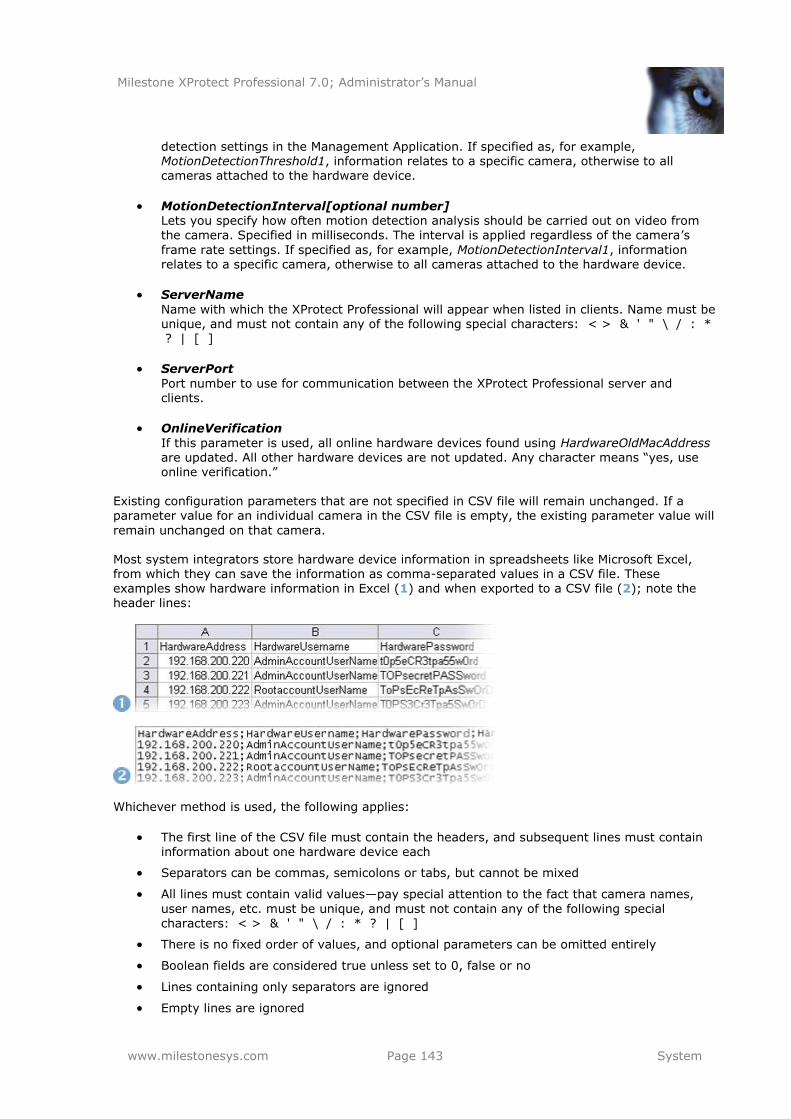
Milestone XProtect Professional 7.0; Administrator’s Manual
www.milestonesys.com Page 143 System
detection settings in the Management Application. If specified as, for example, MotionDetectionThreshold1, information relates to a specific camera, otherwise to all cameras attached to the hardware device.
MotionDetectionInterval[optional number] Lets you specify how often motion detection analysis should be carried out on video from the camera. Specified in milliseconds. The interval is applied regardless of the camera’s
frame rate settings. If specified as, for example, MotionDetectionInterval1, information relates to a specific camera, otherwise to all cameras attached to the hardware device.
ServerName
Name with which the XProtect Professional will appear when listed in clients. Name must be unique, and must not contain any of the following special characters: < > & ' " \ / : * ? | [ ]
ServerPort
Port number to use for communication between the XProtect Professional server and clients.
OnlineVerification
If this parameter is used, all online hardware devices found using HardwareOldMacAddress are updated. All other hardware devices are not updated. Any character means ―yes, use online verification.‖
Existing configuration parameters that are not specified in CSV file will remain unchanged. If a
parameter value for an individual camera in the CSV file is empty, the existing parameter value will
remain unchanged on that camera. Most system integrators store hardware device information in spreadsheets like Microsoft Excel, from which they can save the information as comma-separated values in a CSV file. These examples show hardware information in Excel (1) and when exported to a CSV file (2); note the header lines:
Whichever method is used, the following applies:
The first line of the CSV file must contain the headers, and subsequent lines must contain information about one hardware device each
Separators can be commas, semicolons or tabs, but cannot be mixed
All lines must contain valid values—pay special attention to the fact that camera names,
user names, etc. must be unique, and must not contain any of the following special
characters: < > & ' " \ / : * ? | [ ]
There is no fixed order of values, and optional parameters can be omitted entirely
Boolean fields are considered true unless set to 0, false or no
Lines containing only separators are ignored
Empty lines are ignored
Milestone XProtect Professional 7.0; Administrator’s Manual
www.milestonesys.com Page 144 System
Even though the CSV file format is generally ASCII only, Unicode identifiers are allowed;
even without Unicode identifiers, the entire file or even individual characters are allowed to be Unicode strings
If you need to include separator characters in a value—for example if a camera name is Reception; Camera 1—you can encapsulate the value in quotes to indicate that the separator should not be interpreted as separating values in the file. Such quote-encapsulated values are interpreted as they
appear. If a separator, a quote or a space is needed in a value, the whole value has to be encapsulated in quotes. Leading and trailing spaces outside the quote-encapsulated value are removed, while spaces inside the quote-encapsulated value are maintained. No characters (except spaces) are allowed outside the quote-encapsulated value. A double quote inside a quote-
encapsulated value is interpreted as a single quote. Nested quotes (quotes inside quotes) are not allowed. Some examples (using semicolon as the separator):
"camera"; is interpreted as camera
"cam;""era"; is interpreted as cam;"era
"""camera"""; is interpreted as "camera"
""; is interpreted as an empty string
...; " cam"" era " ;... is interpreted as | cam" era | (where the character | is not part
of the interpretation but only used to show the start and end of the interpretation)
""camera; is not valid as there are characters outside the quote-encapsulated value
"cam" "era"; is not valid as the two quotes are separated with a space and quotes cannot
be nested
"cam"er"a"; is not valid as you cannot nest quotes
cam"era"; is not valid as there are characters outside the quotes
Back Up System Configuration
We recommend that you make regular backups of your XProtect Professional configuration (cameras, schedules, views, etc.) as a disaster recovery measure. While it is rare to lose your configuration, it can happen under unfortunate circumstances. Luckily, it takes only a minute to back up your existing configuration.
The following describes backup of the configuration in XProtect Professional version 7.0. If you
need information about how to back up configuration from an earlier version of XProtect Professional—a typical need when upgrading to XProtect Professional 7.0 from an earlier version—see Upgrade from a Previous Version on page 19. In the following, we assume that you have not changed XProtect Professional’s default configuration path (see page 137), which is C:\Documents and Settings\All Users\Application Data\Milestone\Milestone Surveillance on servers running Windows XP or Windows Server 2003,
and C:\Program Data\Milestone\Milestone Surveillance on servers running all other supported operating systems. If you have changed the default configuration path, you must take your changes into consideration when using the method described in the following.
1. If XProtect Professional is used on a server running Windows XP or Windows Server 2003,
make a copy of the folder C:\Documents and Settings\All Users\Application Data\Milestone\Milestone Surveillance and all of its content. If XProtect Professional is used on a server running any other supported operating system, make a copy of the folder C:\Program Data\Milestone\Milestone Surveillance and all of its content.
Milestone XProtect Professional 7.0; Administrator’s Manual
www.milestonesys.com Page 145 System
2. Open the folder C:\Program Files\Milestone\Milestone Surveillance\devices, and verify if the file devices.ini exists. If the file exists, make a copy of it. The file will exist if you have configured video properties (see page 69) for certain types of cameras; for such cameras,
changes to the properties are stored in the file rather than on the camera itself.
3. Store the copies away from the XProtect Professional server, so that they will not be affected if the server is damaged, stolen or otherwise affected.
Remember that a backup is a snapshot of your XProtect Professional system configuration
at the time of backing up. If you later change your configuration, your backup will not reflect the most recent changes. Therefore, back up your system configuration regularly.
Tip: When you back up your configuration as described, the backup will include restore points (see page 138). This allows you to not only restore the backed-up configuration, but also to revert to an earlier point in that configuration if required.
To restore your backed-up configuration:
1. If XProtect Professional is used on a server running Windows XP or Windows Server 2003, copy the content of the backed-up Milestone Surveillance folder into C:\Documents and Settings\All Users\Application Data\Milestone\Milestone Surveillance. If XProtect Professional is used on a server running any other supported operating system,
copy the content of the backed-up Milestone Surveillance folder into C:\Program Data\Milestone\Milestone Surveillance
2. If you backed up the file devices.ini, copy the file into C:\Program Files\Milestone\Milestone
Surveillance\devices
Handle Daylight Saving Time
Daylight saving time (DST, also known as summer time) is the practice of advancing clocks in order for evenings to have more daylight and mornings to have less. Typically, clocks are adjusted forward one hour sometime during the spring season and adjusted backward sometime during the fall season, hence
the saying spring forward, fall back. Note that use of DST varies
between countries/regions. When working with a surveillance system, which is inherently time-sensitive, it is important to know how the system handles DST.
Spring: Switch from Standard Time
to DST
The change from standard time to DST is not much of an issue since you jump one hour forward. Typically, the clock jumps forward from 02:00 standard time to 03:00 DST, and the day thus has 23 hours. In that case, there is simply no data between 02:00 and 03:00 in the morning since that hour, for that day, did not exist.
Fall: Switch from DST to Standard Time
When you switch from DST to standard time in the fall, you jump one hour back. Typically, the clock jumps backward from 02:00 DST to 01:00 standard time, repeating that hour, and the day thus has 25 hours. In that case, you will reach 01:59:59, then immediately revert back to
Milestone XProtect Professional 7.0; Administrator’s Manual
www.milestonesys.com Page 146 System
01:00:00. If the system did not react, it would essentially re-record that hour, so the first instance of, for example, 01:30 would be overwritten by the second instance of 01:30.
Because of this, XProtect Professional will forcefully archive the current video in the event that the system time changes by more than five minutes. The first instance of the 01:00 hour will not be viewable directly from clients. However, the data is recorded and safe, and it can be browsed using the Viewer application (see page 168) by opening the archived database directly.
Improve Stability with 3 GB Operating
System Virtual Memory
Microsoft Windows 32-bit operating systems can address 4 GB of virtual memory. The operating system kernel reserves 2 GB for itself, and each individual running process is allowed to address another 2 GB. This is Windows’ default setting, and for the vast majority of XProtect Professional installations it works fine.
As from XProtect Professional 6.5a, the main components of the server—the Recording Server service and the Image Server service—have been compiled with the LARGEADDRESSAWARE flag. This means you can optimize the memory usage of XProtect Professional’s Recording Server and Image Server services by configuring your 32-bit Windows operating system so that it restricts the kernel to 1GB of memory, leaving 3GB of address space for processes compiled with the
LARGEADDRESSAWARE flag.
This should improve the stability of especially the Recording Server service by allowing it to exceed the previous 2 GB virtual memory limit, making it possible for it to use up to 3 GB of memory. The change in Windows configuration is known as 3 GB switching.
When Is 3 GB Switching Relevant?
For very large XProtect Professional installations and/or for installations with many megapixel cameras it can be relevant to change Windows’ settings so that only 1 GB of virtual memory is reserved for the operating system kernel, leaving 3 GB for running processes.
If using Windows’ default setting, with only 2 GB virtual memory reserved for running processes, it
has been seen that the Recording Server service in very large installations of XProtect Professional may:
Behave erratically if getting very close to the 2 GB virtual memory limit. Symptoms can
include database corruption, and client-server or camera-server communication errors.
Become unstable and crash if exceeding the 2 GB virtual memory limit. During such
crashes, the code managing the surveillance system databases is not closed properly, and databases will become corrupt. In case of a crash, Windows will normally restart the Recording Server service. However, when the Recording Server service is restarted, one of its first tasks will be to repair the databases. The database repair process can in some cases take several hours, depending on the amount of data in the corrupted databases.
If you experience such problems, and you run XProtect Professional 6.5a or newer, making
Windows use 3 GB for running processes is likely to solve the problems. If you have not experienced such problems, but you run XProtect Professional 6.5a or newer and your XProtect Professional installation is very large and/or features many megapixel cameras, 3 GB switching is likely to help prevent the problems from occurring.
Milestone XProtect Professional 7.0; Administrator’s Manual
www.milestonesys.com Page 147 System
The way to configure 32-bit Windows to be LARGEADDRESSAWARE depends on your type of Windows operating system. In the following, you will see two methods outlining Microsoft’s recommended procedure for increasing the per-process memory limit to 3 GB. Use the first method
if running Windows XP Professional or Windows Server 2003. Use the second method if running Windows 2008 Server, Windows Vista Business, Windows Vista Enterprise or Windows Vista Ultimate.
What to Do on Window XP Professional or Windows
Server 2003
IMPORTANT: Improper modification of boot.ini can render the operating system inoperable. Milestone Systems do not assume any responsibility for changes you make to the operating system.
Adding the 3 GB Switch
The following technique can be used to add the 3 GB switch to the boot.ini file. From a command prompt, enter the following to add the 3 GB switch to the end of the first line of the operating system section in the boot.ini file (requires administrative privileges):
BOOTCFG /RAW "/3GB" /A /ID 1
Where
/RAW specifies the operating system options for the boot entry. The previous operating
system options will be modified.
"/3GB" specifies the 3 GB switch.
/A specifies that the operating system options entered with the /RAW switch will be
appended to the existing operating system options.
/ID specifies the boot entry ID in the OS Load Options section of the boot.ini file to add the
operating system options to. The boot entry ID number can be obtained by performing the
command BOOTCFG /QUERY (this displays the contents of the boot.ini file) at the command
prompt.
A reboot is required after editing the boot.ini file for the changes to take effect.
Removing the 3 GB Switch
If you want to undo the 3 GB switch mentioned above, follow this procedure:
Select Start > Control Panel, and double-click the System icon. Select the Advanced tab, and click the Settings button in the Startup and Recovery section. Click the Edit button in the System
Startup section. The boot.ini file will launch in an editor. Remove the "/3GB" from the end of the
appropriate boot entry line under the [operating systems] section. Save and close the file. Click OK in the Startup and Recovery section. A reboot is required after editing the boot.ini file for the changes to take effect.
What to Do on Windows 2008 Server or Windows Vista
IMPORTANT: Improper modification of the operating system boot entry can render the operating system inoperable. Milestone Systems do not assume any responsibility for changes you make to the operating system.
Milestone XProtect Professional 7.0; Administrator’s Manual
www.milestonesys.com Page 148 System
Adding the 3 GB Switch
Select Start > All Programs > Accessories, right-click Command Prompt, and select Run as administrator, then click Continue. Enter the following command to add the 3 GB switch to the current operating system boot entry:
BCDEDIT /SET INCREASEUSERVA 3072
Where
USERVA Specifies an alternate amount of user-mode virtual address space for operating
systems.
3072 Specifies 3 GB (3072 MB).
A reboot is required after editing the boot configuration data store for the changes to take effect.
Removing the /3GB Switch
Select Start > All Programs > Accessories, right-click Command Prompt, and select Run as administrator, then click Continue. Enter the following command to remove the 3 GB switch from
the current operating system boot entry:
BCDEDIT /DELETEVALUE INCREASEUSERVA
A reboot is required after editing the boot configuration data store for the changes to take effect.
Protect Recording Databases from Corruption
In the Management Application you can select which action to take if a camera database becomes corrupted. The actions include several database repair options. While being able to select such actions is highly valuable, it is of course even better to take steps to ensure that your camera databases do not become corrupted.
Power Outages: Use a UPS
The single biggest reason for corrupt databases is the surveillance system server being shut down
abruptly, without files being saved and without the operating system being closed down properly. This may happen due to power outages, due to somebody accidentally pulling out the server’s power cable, or similar. The best way of protecting your surveillance system server from being shut down abruptly is to equip your surveillance system server with a UPS (Uninterruptible Power Supply).
The UPS works as a battery-driven secondary power source, providing the necessary power for saving open files and safely powering down your system in the event of power irregularities. UPSs
vary in sophistication, but many UPSs include software for automatically saving open files, for alerting system administrators, etc. Selecting the right type of UPS for your organization’s environment is an individual process. When
assessing your needs, however, do bear in mind the amount of runtime you will require the UPS to be able to provide if the power fails; saving open files and shutting down an operating system properly may take several minutes.
Milestone XProtect Professional 7.0; Administrator’s Manual
www.milestonesys.com Page 149 System
Windows Task Manager: Be Careful when Ending
Processes
When working in Windows Task Manager, be careful not to end any processes which affect the surveillance system. If you end an application or system service by clicking End Process in the Windows Task Manager, the process in question will not be given the chance to save its state or
data before it is terminated. This may in turn lead to corrupt camera databases. Windows Task Manager will typically display a warning if you attempt to end a process. Unless you are absolutely sure that ending the process will not affect the surveillance system, make sure you
click the No button when the warning message asks you if you really want to terminate the process.
Hard Disk Failure: Protect Your Drives
Hard disk drives are mechanical devices, and as such they are vulnerable to external factors. The following are examples of external factors which may damage hard disk drives and lead to corrupt camera databases:
Vibration (make sure the surveillance system server and its surroundings are stable)
Strong heat (make sure the server has adequate ventilation)
Strong magnetic fields (avoid)
Power outages (make sure you use a UPS; see more information in the previous)
Static electricity (make sure you ground yourself if you are going to handle a hard disk drive).
Fire, water, etc. (avoid)
Milestone XProtect Professional 7.0; Administrator’s Manual
www.milestonesys.com Page 150 Drivers
Drivers
Update Video Device Drivers
Video device drivers are small programs used for controlling/communicating with the camera devices connected to the XProtect Professional system. Video device drivers are installed automatically during the initial installation of your XProtect Professional system. However, new
versions of video device drivers—so-called Device Packs—are released and made available for free on www.milestonesys.com from time to time. We recommend that you always use the latest version of video device drivers. When updating
video device drivers, there is no need to remove the old video device drivers first; simply install the latest version on top of any old version you may have. IMPORTANT: When you install new video device drivers, your system will not be able to communicate with camera devices from the moment you begin the installation until the moment installation is complete and you have restarted the Recording Server service. Usually, the process takes no longer than a few minutes, but it is highly recommended that you perform the update at a
time when you do not expect important incidents to take place.
1. On the XProtect Professional server on which you want to install the new video device
drivers version, shut down any running surveillance software, including any running Recording Server service.
2. Double-click the downloaded video device driver file DeviceInstaller.exe to begin installation. Depending on your security settings, one or more Windows security warnings may appear after you click the link. If such security warnings appear, accept security warnings by clicking the Run button (button may have other name; exact button name depends on your operating system version).
3. Select required language, and click OK. This will open the Video Device Driver Setup
Wizard, which will guide you through the installation. Click the Next button and follow the wizard.
4. When the wizard is complete, remember to start the Recording Server service again.
Driver IDs
You find the list of hardware driver IDs for use with the Replace Hardware Wizard as an appendix on page 180 of this manual.
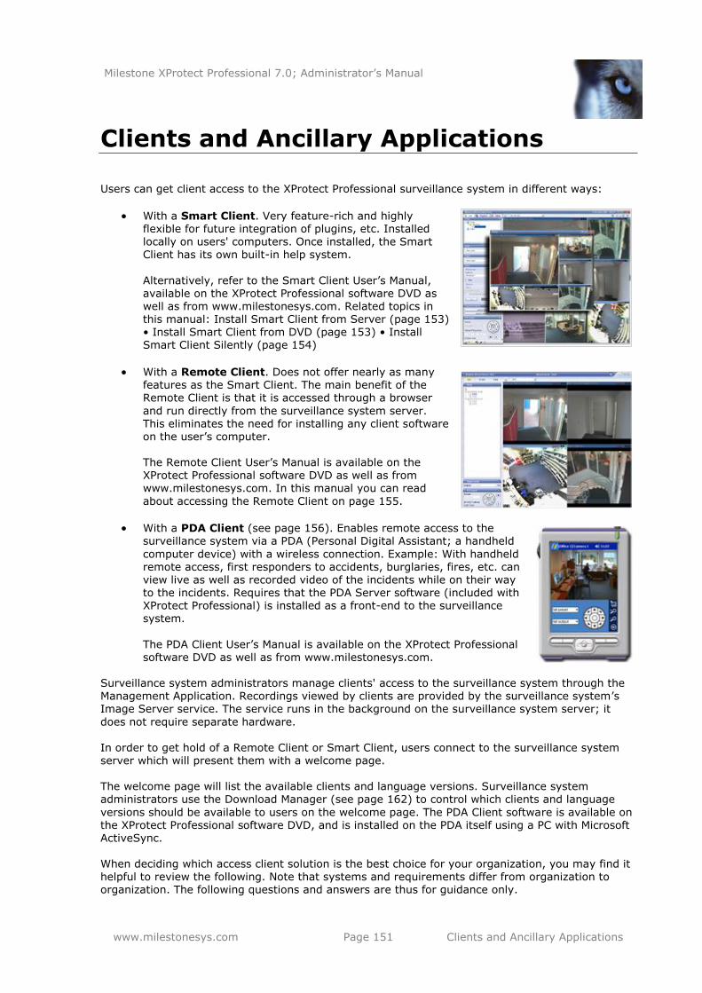
Milestone XProtect Professional 7.0; Administrator’s Manual
www.milestonesys.com Page 151 Clients and Ancillary Applications
Clients and Ancillary Applications
Users can get client access to the XProtect Professional surveillance system in different ways:
With a Smart Client. Very feature-rich and highly flexible for future integration of plugins, etc. Installed locally on users' computers. Once installed, the Smart Client has its own built-in help system.
Alternatively, refer to the Smart Client User’s Manual, available on the XProtect Professional software DVD as well as from www.milestonesys.com. Related topics in this manual: Install Smart Client from Server (page 153) • Install Smart Client from DVD (page 153) • Install Smart Client Silently (page 154)
With a Remote Client. Does not offer nearly as many features as the Smart Client. The main benefit of the Remote Client is that it is accessed through a browser
and run directly from the surveillance system server. This eliminates the need for installing any client software on the user’s computer.
The Remote Client User’s Manual is available on the XProtect Professional software DVD as well as from www.milestonesys.com. In this manual you can read
about accessing the Remote Client on page 155.
With a PDA Client (see page 156). Enables remote access to the surveillance system via a PDA (Personal Digital Assistant; a handheld
computer device) with a wireless connection. Example: With handheld remote access, first responders to accidents, burglaries, fires, etc. can view live as well as recorded video of the incidents while on their way to the incidents. Requires that the PDA Server software (included with XProtect Professional) is installed as a front-end to the surveillance system.
The PDA Client User’s Manual is available on the XProtect Professional software DVD as well as from www.milestonesys.com.
Surveillance system administrators manage clients' access to the surveillance system through the Management Application. Recordings viewed by clients are provided by the surveillance system’s Image Server service. The service runs in the background on the surveillance system server; it
does not require separate hardware. In order to get hold of a Remote Client or Smart Client, users connect to the surveillance system server which will present them with a welcome page. The welcome page will list the available clients and language versions. Surveillance system administrators use the Download Manager (see page 162) to control which clients and language
versions should be available to users on the welcome page. The PDA Client software is available on the XProtect Professional software DVD, and is installed on the PDA itself using a PC with Microsoft ActiveSync. When deciding which access client solution is the best choice for your organization, you may find it helpful to review the following. Note that systems and requirements differ from organization to organization. The following questions and answers are thus for guidance only.
Milestone XProtect Professional 7.0; Administrator’s Manual
www.milestonesys.com Page 152 Clients and Ancillary Applications
Do you require a handheld solution?
Yes: Use the PDA Client/Server solution. If required, you can of course combine the PDA
solution with other remote access solutions, such as the Smart Client.
No: Determine your needs based on the questions and answers provided in the following.
Is it acceptable to install client software on remote users' computers?
Yes: Use the Smart Client.
No: Use the Remote Client; remote users run the Remote Client straight from the XProtect
Professional server.
Will you require a large amount of future flexibility from your remote access solution?
Yes: Use the Smart Client. The Smart Client offers a high degree of flexibility for
integration of new features, plugins, etc.
No: Use the Remote Client.
Do you require a very feature-rich client application?
Yes: Use the Smart Client. The Smart Client offers considerably more features than the
other solutions.
No: Use the Remote Client.
Do you require a large amount of flexibility re. remote users' ability to export data for
use as evidence, etc.?
Yes: Use the Smart Client. The Smart Client offers the ability to—individual user rights
permitting—export data in the AVI (movie clip) and JPEG (still image) as well as XProtect Professional database formats.
No: Use the Remote Client. The Remote Client offers the ability to—individual user rights
permitting—export evidence in the AVI and JPEG formats. Will you use a .NET-based client application?
The. NET software development platform allows the interconnection of computers and services for the exchange and combination of data and objects. The platform makes extensive use of so-called web services, which provide the ability to use the web rather than single applications for various services. This in turn provides the ability for centralized data storage as well as automated updating and synchronization of information. The .NET platform enhances software developers' ability to create re-usable and customizable modules, which makes it possible to develop highly
flexible software solutions. You can therefore, as a rule of thumb, expect .NET-based software to be highly flexible, ready for integration of new features, plugins, etc. However, organizations and their requirements are different, and some organizations find that the high degree of interconnection of services and computers inherent in a .NET-based solution is not desirable. Instead, such organizations rely on more classic Windows solutions.
Yes: Use the Smart Client. The .NET-based Smart Client offers more features for remote
users than the other solutions. .NET Framework, downloadable from http://www.microsoft.com/downloads/, is required on computers running the Smart Client. See separate the Smart Client documentation for exact system requirements.
No: Use the Remote Client. The Remote Client is not a .NET-based solution.
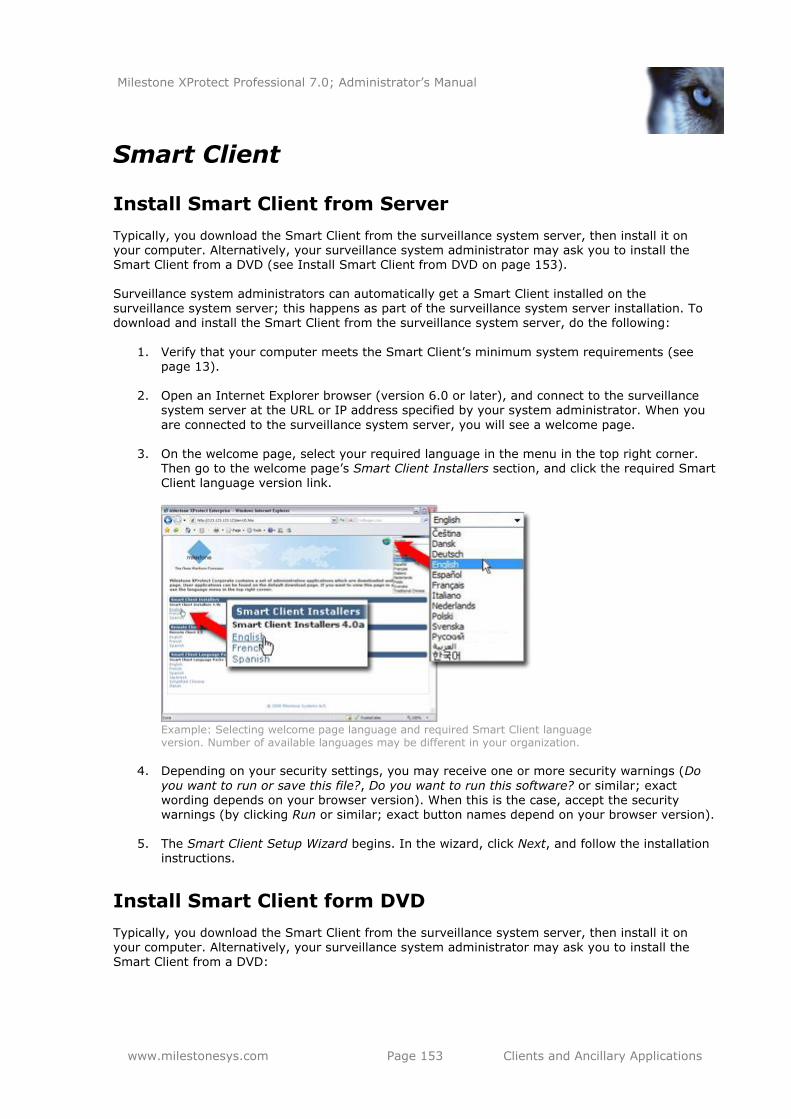
Milestone XProtect Professional 7.0; Administrator’s Manual
www.milestonesys.com Page 153 Clients and Ancillary Applications
Smart Client
Install Smart Client from Server
Typically, you download the Smart Client from the surveillance system server, then install it on your computer. Alternatively, your surveillance system administrator may ask you to install the Smart Client from a DVD (see Install Smart Client from DVD on page 153). Surveillance system administrators can automatically get a Smart Client installed on the
surveillance system server; this happens as part of the surveillance system server installation. To download and install the Smart Client from the surveillance system server, do the following:
1. Verify that your computer meets the Smart Client’s minimum system requirements (see
page 13).
2. Open an Internet Explorer browser (version 6.0 or later), and connect to the surveillance system server at the URL or IP address specified by your system administrator. When you
are connected to the surveillance system server, you will see a welcome page.
3. On the welcome page, select your required language in the menu in the top right corner. Then go to the welcome page’s Smart Client Installers section, and click the required Smart Client language version link.
Example: Selecting welcome page language and required Smart Client language version. Number of available languages may be different in your organization.
4. Depending on your security settings, you may receive one or more security warnings (Do
you want to run or save this file?, Do you want to run this software? or similar; exact wording depends on your browser version). When this is the case, accept the security warnings (by clicking Run or similar; exact button names depend on your browser version).
5. The Smart Client Setup Wizard begins. In the wizard, click Next, and follow the installation
instructions.
Install Smart Client form DVD
Typically, you download the Smart Client from the surveillance system server, then install it on your computer. Alternatively, your surveillance system administrator may ask you to install the Smart Client from a DVD:
Milestone XProtect Professional 7.0; Administrator’s Manual
www.milestonesys.com Page 154 Clients and Ancillary Applications
1. Verify that your computer meets the Smart Client’s minimum system requirements (see page 13).
2. Insert the surveillance system software DVD, wait for a short while, select required language, then click the Install Milestone XProtect Smart Client link.
3. Depending on your security settings, you may receive one or more security warnings (Do you want to run or save this file?, Do you want to run this software? or similar; exact wording depends on your browser version). When this is the case, accept the security
warnings (by clicking Run or similar; exact button names depend on your browser version).
4. When the installation wizard starts, click Next to continue the installation and follow the steps in the installation wizard.
Install Smart Client Silently
For surveillance system administrators, it is possible to deploy the Smart Client to users’ computers using tools such as Microsoft Systems Management Server (SMS). Such tools let administrators
build up databases of hardware and software on local networks. The databases can then—among other things—be used for distributing and installing software applications, such as the Smart Client, over local networks.
1. Locate the self-extracting Smart Client installation (.exe) file.
You find the file in a subfolder under the folder httpdocs. The httpdocs folder is located
under the folder in which your Milestone surveillance software is installed. The path would thus typically be C:\Program Files\Milestone\Milestone Surveillance\httpdocs\Smart Client Installers\[version number]\[language]\[language code]. For example, an English-language version of the Smart Client installation file could be located at C:\Program Files\Milestone\Milestone Surveillance\httpdocs\Smart Client Installers\3.5b\English\en-US.
2. With an extraction tool, such as WinZip® or similar, extract the files contained in the
installation file to a folder of your choice. When extraction is done, the folder to which you extracted will contain a small number of files, among these a file with the extension .msi. The .msi file is a Microsoft Windows
Installer installation package covering the complete Smart Client installation procedure.
3. You can now use your systems management tool to deploy the .msi file. Alternatively, you can simply copy the msi. file to required computers, and run the .msi file from a command prompt. Examples:
C:\Documents and Settings\you>msiexec /i "C:\folder_to_which_file_
was_copied\SmartClientInstaller.msi" /quiet
where msiexec calls the Windows Installer, the parameter /i indicates that you want to
install, and the parameter /quiet indicates a silent installation.
On the target computer, the Smart Client is by default installed in C:\Program
Files\Milestone\Milestone Smart Client. With the TARGETDIR property, you are able to
specify a different installation folder. Example:
C:\Documents and Settings\you>msiexec /I "C:\folder_to_which_file_
was_copied\SmartClientInstaller.msi" /quiet TARGETDIR=C:\required_
installation_folder\
Milestone XProtect Professional 7.0; Administrator’s Manual
www.milestonesys.com Page 155 Clients and Ancillary Applications
Remote Client
The main benefit of the Remote Client is that it is accessed through a browser and run directly from
the surveillance system server. This eliminates the need for installing any client software on the user’s computer. To access the Remote Client:
1. Open an Internet Explorer browser (version 6.0 or later), and connect to surveillance system server. The address format is typically:
http://[surveillance_system_server_address]:[port_number]
Tip: The port number is only required if using another port than the default port for XProtect Professional’s Image Server service, port 80. When you connect to the server, you will see a welcome page. On the welcome page, click the Remote Client link in order to view the Remote Client login dialog.
2. To log in, specify information in the following fields:
Previous Logins: Only available if you have logged in before. Lets you reuse previously specified login details (except any password, which you must always
type yourself). This can greatly speed up the login process.
Address: Type the URL or IP address of the surveillance system server.
Port: Specify the port number to use when logging in to the Remote Client. In
most circumstances, port 80 is used.
Authentication: Select required authentication method.
o Windows (current user), with which you will be authenticated through your
current Windows login, and do not have to specify any user name or password. This is the default authentication method, that is the method which is automatically used unless you select another method.
o Windows, with which you will be authenticated through your Windows login,
but you will need to type your Windows user name and password.
o Basic, with which you will be authenticated through a user/password combination defined on the surveillance system server.
Username: Type your user name. The user name is case-sensitive, that is there is a difference between typing, for example, amanda and Amanda.
Password: Type your password. The password is case-sensitive.
3. Click the Login link. After a short wait, you get access to the Remote Client. Content in the
Remote Client is grouped on three tabs: Live, Playback and Setup.
The Live tab is used for viewing live video from cameras, the Playback tab is used for finding and playing back recorded video, and the Setup tab is used for configuring the Remote Client.
Where can I find more information about the Remote Client? Refer to the Remote Client User’s Manual, available on the XProtect Professional software DVD as well as from www.milestonesys.com.
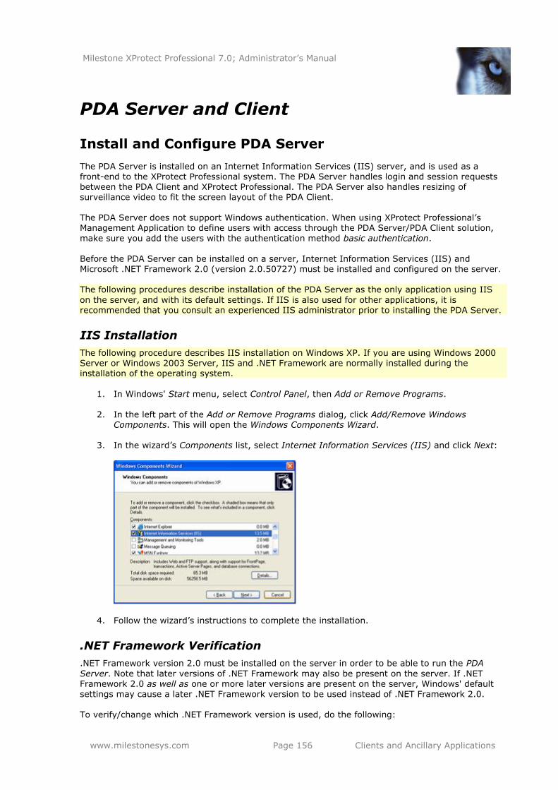
Milestone XProtect Professional 7.0; Administrator’s Manual
www.milestonesys.com Page 156 Clients and Ancillary Applications
PDA Server and Client
Install and Configure PDA Server
The PDA Server is installed on an Internet Information Services (IIS) server, and is used as a front-end to the XProtect Professional system. The PDA Server handles login and session requests between the PDA Client and XProtect Professional. The PDA Server also handles resizing of surveillance video to fit the screen layout of the PDA Client.
The PDA Server does not support Windows authentication. When using XProtect Professional’s Management Application to define users with access through the PDA Server/PDA Client solution,
make sure you add the users with the authentication method basic authentication. Before the PDA Server can be installed on a server, Internet Information Services (IIS) and Microsoft .NET Framework 2.0 (version 2.0.50727) must be installed and configured on the server. The following procedures describe installation of the PDA Server as the only application using IIS
on the server, and with its default settings. If IIS is also used for other applications, it is recommended that you consult an experienced IIS administrator prior to installing the PDA Server.
IIS Installation
The following procedure describes IIS installation on Windows XP. If you are using Windows 2000
Server or Windows 2003 Server, IIS and .NET Framework are normally installed during the installation of the operating system.
1. In Windows' Start menu, select Control Panel, then Add or Remove Programs.
2. In the left part of the Add or Remove Programs dialog, click Add/Remove Windows Components. This will open the Windows Components Wizard.
3. In the wizard’s Components list, select Internet Information Services (IIS) and click Next:
4. Follow the wizard’s instructions to complete the installation.
.NET Framework Verification
.NET Framework version 2.0 must be installed on the server in order to be able to run the PDA
Server. Note that later versions of .NET Framework may also be present on the server. If .NET Framework 2.0 as well as one or more later versions are present on the server, Windows' default settings may cause a later .NET Framework version to be used instead of .NET Framework 2.0. To verify/change which .NET Framework version is used, do the following:
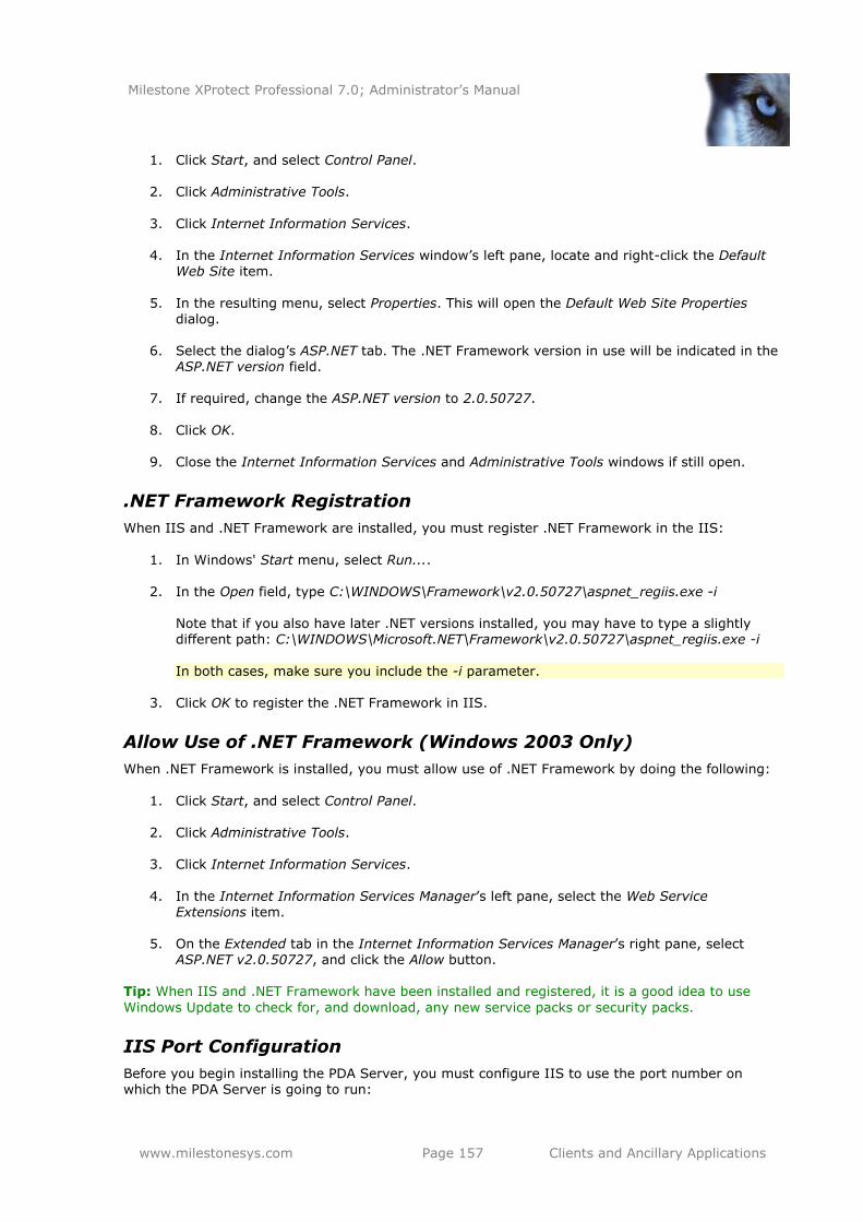
Milestone XProtect Professional 7.0; Administrator’s Manual
www.milestonesys.com Page 157 Clients and Ancillary Applications
1. Click Start, and select Control Panel.
2. Click Administrative Tools.
3. Click Internet Information Services.
4. In the Internet Information Services window’s left pane, locate and right-click the Default
Web Site item.
5. In the resulting menu, select Properties. This will open the Default Web Site Properties dialog.
6. Select the dialog’s ASP.NET tab. The .NET Framework version in use will be indicated in the
ASP.NET version field.
7. If required, change the ASP.NET version to 2.0.50727.
8. Click OK.
9. Close the Internet Information Services and Administrative Tools windows if still open.
.NET Framework Registration
When IIS and .NET Framework are installed, you must register .NET Framework in the IIS:
1. In Windows' Start menu, select Run....
2. In the Open field, type C:\WINDOWS\Framework\v2.0.50727\aspnet_regiis.exe -i Note that if you also have later .NET versions installed, you may have to type a slightly different path: C:\WINDOWS\Microsoft.NET\Framework\v2.0.50727\aspnet_regiis.exe -i
In both cases, make sure you include the -i parameter.
3. Click OK to register the .NET Framework in IIS.
Allow Use of .NET Framework (Windows 2003 Only)
When .NET Framework is installed, you must allow use of .NET Framework by doing the following:
1. Click Start, and select Control Panel.
2. Click Administrative Tools.
3. Click Internet Information Services.
4. In the Internet Information Services Manager’s left pane, select the Web Service Extensions item.
5. On the Extended tab in the Internet Information Services Manager’s right pane, select ASP.NET v2.0.50727, and click the Allow button.
Tip: When IIS and .NET Framework have been installed and registered, it is a good idea to use
Windows Update to check for, and download, any new service packs or security packs.
IIS Port Configuration
Before you begin installing the PDA Server, you must configure IIS to use the port number on which the PDA Server is going to run:
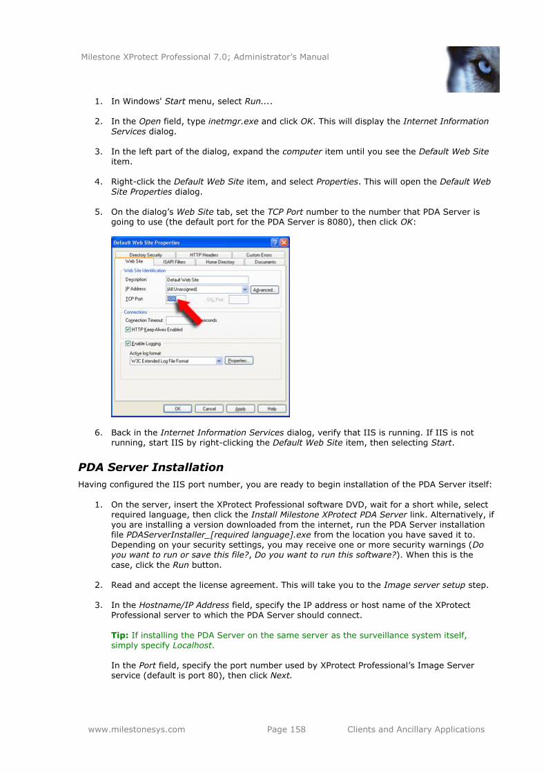
Milestone XProtect Professional 7.0; Administrator’s Manual
www.milestonesys.com Page 158 Clients and Ancillary Applications
1. In Windows' Start menu, select Run....
2. In the Open field, type inetmgr.exe and click OK. This will display the Internet Information
Services dialog.
3. In the left part of the dialog, expand the computer item until you see the Default Web Site item.
4. Right-click the Default Web Site item, and select Properties. This will open the Default Web
Site Properties dialog.
5. On the dialog’s Web Site tab, set the TCP Port number to the number that PDA Server is going to use (the default port for the PDA Server is 8080), then click OK:
6. Back in the Internet Information Services dialog, verify that IIS is running. If IIS is not running, start IIS by right-clicking the Default Web Site item, then selecting Start.
PDA Server Installation
Having configured the IIS port number, you are ready to begin installation of the PDA Server itself:
1. On the server, insert the XProtect Professional software DVD, wait for a short while, select
required language, then click the Install Milestone XProtect PDA Server link. Alternatively, if you are installing a version downloaded from the internet, run the PDA Server installation file PDAServerInstaller_[required language].exe from the location you have saved it to. Depending on your security settings, you may receive one or more security warnings (Do you want to run or save this file?, Do you want to run this software?). When this is the
case, click the Run button.
2. Read and accept the license agreement. This will take you to the Image server setup step.
3. In the Hostname/IP Address field, specify the IP address or host name of the XProtect Professional server to which the PDA Server should connect.
Tip: If installing the PDA Server on the same server as the surveillance system itself, simply specify Localhost. In the Port field, specify the port number used by XProtect Professional’s Image Server service (default is port 80), then click Next.
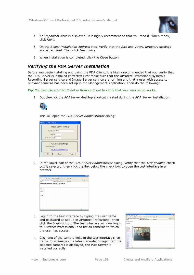
Milestone XProtect Professional 7.0; Administrator’s Manual
www.milestonesys.com Page 159 Clients and Ancillary Applications
4. An Important Note is displayed; it is highly recommended that you read it. When ready, click Next.
5. On the Select Installation Address step, verify that the Site and Virtual directory settings are as required. Then click Next twice.
6. When installation is completed, click the Close button.
Verifying the PDA Server Installation
Before you begin installing and using the PDA Client, it is highly recommended that you verify that
the PDA Server is installed correctly: First make sure that the XProtect Professional system’s Recording Server service and Image Server service are running and that a user with access to relevant cameras has been set up in the Management Application. Then do the following: Tip: You can use a Smart Client or Remote Client to verify that your user setup works.
1. Double-click the PDAServer desktop shortcut created during the PDA Server installation:
This will open the PDA Server Administrator dialog:
2. In the lower half of the PDA Server Administrator dialog, verify that the Test enabled check box is selected, then click the link below the check box to open the test interface in a browser:
3. Log in to the test interface by typing the user name and password as set up in XProtect Professional, then click the Login button. The test interface will now log in
to XProtect Professional, and list all cameras to which the user has access.
4. Click one of the camera links in the test interface’s left
frame. If an image (the latest recorded image from the selected camera) is displayed, the PDA Server is installed correctly.
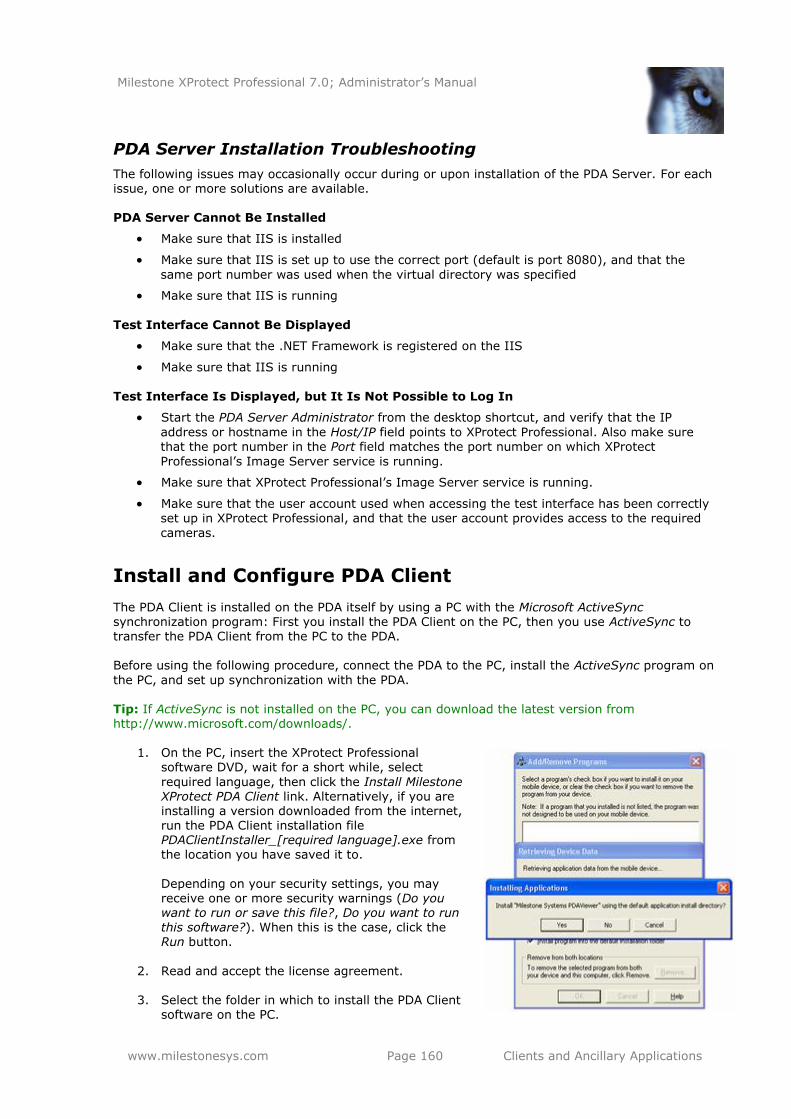
Milestone XProtect Professional 7.0; Administrator’s Manual
www.milestonesys.com Page 160 Clients and Ancillary Applications
PDA Server Installation Troubleshooting
The following issues may occasionally occur during or upon installation of the PDA Server. For each issue, one or more solutions are available. PDA Server Cannot Be Installed
Make sure that IIS is installed
Make sure that IIS is set up to use the correct port (default is port 8080), and that the
same port number was used when the virtual directory was specified
Make sure that IIS is running
Test Interface Cannot Be Displayed
Make sure that the .NET Framework is registered on the IIS
Make sure that IIS is running
Test Interface Is Displayed, but It Is Not Possible to Log In
Start the PDA Server Administrator from the desktop shortcut, and verify that the IP
address or hostname in the Host/IP field points to XProtect Professional. Also make sure that the port number in the Port field matches the port number on which XProtect
Professional’s Image Server service is running.
Make sure that XProtect Professional’s Image Server service is running.
Make sure that the user account used when accessing the test interface has been correctly set up in XProtect Professional, and that the user account provides access to the required
cameras.
Install and Configure PDA Client
The PDA Client is installed on the PDA itself by using a PC with the Microsoft ActiveSync synchronization program: First you install the PDA Client on the PC, then you use ActiveSync to transfer the PDA Client from the PC to the PDA. Before using the following procedure, connect the PDA to the PC, install the ActiveSync program on
the PC, and set up synchronization with the PDA.
Tip: If ActiveSync is not installed on the PC, you can download the latest version from http://www.microsoft.com/downloads/.
1. On the PC, insert the XProtect Professional software DVD, wait for a short while, select
required language, then click the Install Milestone XProtect PDA Client link. Alternatively, if you are installing a version downloaded from the internet, run the PDA Client installation file PDAClientInstaller_[required language].exe from the location you have saved it to.
Depending on your security settings, you may receive one or more security warnings (Do you want to run or save this file?, Do you want to run
this software?). When this is the case, click the Run button.
2. Read and accept the license agreement.
3. Select the folder in which to install the PDA Client software on the PC.
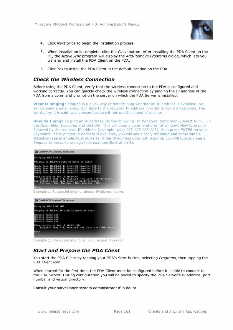
Milestone XProtect Professional 7.0; Administrator’s Manual
www.milestonesys.com Page 161 Clients and Ancillary Applications
4. Click Next twice to begin the installation process.
5. When installation is complete, click the Close button. After installing the PDA Client on the
PC, the ActiveSync program will display the Add/Remove Programs dialog, which lets you transfer and install the PDA Client on the PDA.
6. Click Yes to install the PDA Client in the default location on the PDA.
Check the Wireless Connection
Before using the PDA Client, verify that the wireless connection to the PDA is configured and
working correctly. You can quickly check the wireless connection by pinging the IP address of the PDA from a command prompt on the server on which the PDA Server is installed. What is pinging? Pinging is a quick way of determining whether an IP address is available; you simply send a small amount of data to the required IP address in order to see if it responds. The word ping, it is said, was chosen because it mirrors the sound of a sonar.
How do I ping? To ping an IP address, do the following: In Windows' Start menu, select Run.... In the Open field, type cmd and click OK. This will open a command prompt window. Now type ping followed by the required IP address (example: ping 123.123.123.123), then press ENTER on your keyboard. If the pinged IP address is available, you will see a reply message and some simple statistics (see example illustration 1); if the IP address does not respond, you will typically see a Request timed out message (see example illustration 2).
Example 1: Successful pinging; pinged IP address replies
Example 2: Unsuccessful pinging; ping request times out
Start and Prepare the PDA Client
You start the PDA Client by tapping your PDA’s Start button, selecting Programs, then tapping the PDA Client icon.
When started for the first time, the PDA Client must be configured before it is able to connect to the PDA Server. During configuration you will be asked to specify the PDA Server’s IP address, port number and virtual directory. Consult your surveillance system administrator if in doubt.
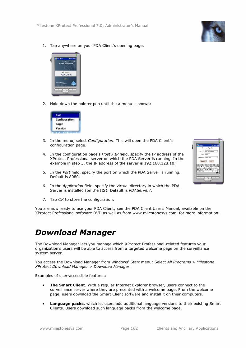
Milestone XProtect Professional 7.0; Administrator’s Manual
www.milestonesys.com Page 162 Clients and Ancillary Applications
1. Tap anywhere on your PDA Client’s opening page.
2. Hold down the pointer pen until the a menu is shown:
3. In the menu, select Configuration. This will open the PDA Client’s configuration page.
4. In the configuration page’s Host / IP field, specify the IP address of the
XProtect Professional server on which the PDA Server is running. In the example in step 3, the IP address of the server is 192.168.128.10.
5. In the Port field, specify the port on which the PDA Server is running.
Default is 8080.
6. In the Application field, specify the virtual directory in which the PDA Server is installed (on the IIS). Default is PDAServer/.
7. Tap OK to store the configuration. You are now ready to use your PDA Client; see the PDA Client User’s Manual, available on the XProtect Professional software DVD as well as from www.milestonesys.com, for more information.
Download Manager
The Download Manager lets you manage which XProtect Professional-related features your organization’s users will be able to access from a targeted welcome page on the surveillance system server. You access the Download Manager from Windows' Start menu: Select All Programs > Milestone XProtect Download Manager > Download Manager.
Examples of user-accessible features:
The Smart Client. With a regular Internet Explorer browser, users connect to the surveillance server where they are presented with a welcome page. From the welcome
page, users download the Smart Client software and install it on their computers.
Language packs, which let users add additional language versions to their existing Smart Clients. Users download such language packs from the welcome page.
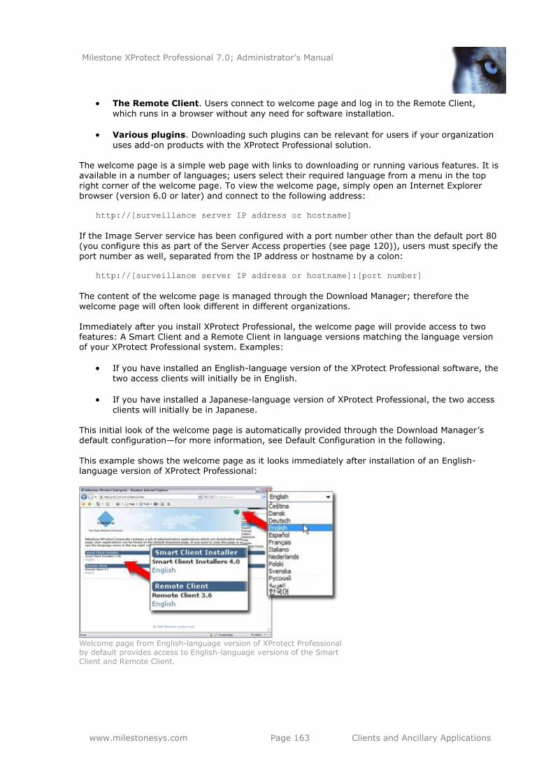
Milestone XProtect Professional 7.0; Administrator’s Manual
www.milestonesys.com Page 163 Clients and Ancillary Applications
The Remote Client. Users connect to welcome page and log in to the Remote Client,
which runs in a browser without any need for software installation.
Various plugins. Downloading such plugins can be relevant for users if your organization
uses add-on products with the XProtect Professional solution. The welcome page is a simple web page with links to downloading or running various features. It is available in a number of languages; users select their required language from a menu in the top right corner of the welcome page. To view the welcome page, simply open an Internet Explorer browser (version 6.0 or later) and connect to the following address:
http://[surveillance server IP address or hostname]
If the Image Server service has been configured with a port number other than the default port 80 (you configure this as part of the Server Access properties (see page 120)), users must specify the port number as well, separated from the IP address or hostname by a colon:
http://[surveillance server IP address or hostname]:[port number]
The content of the welcome page is managed through the Download Manager; therefore the
welcome page will often look different in different organizations. Immediately after you install XProtect Professional, the welcome page will provide access to two features: A Smart Client and a Remote Client in language versions matching the language version of your XProtect Professional system. Examples:
If you have installed an English-language version of the XProtect Professional software, the
two access clients will initially be in English.
If you have installed a Japanese-language version of XProtect Professional, the two access
clients will initially be in Japanese. This initial look of the welcome page is automatically provided through the Download Manager’s default configuration—for more information, see Default Configuration in the following.
This example shows the welcome page as it looks immediately after installation of an English-language version of XProtect Professional:
Welcome page from English-language version of XProtect Professional by default provides access to English-language versions of the Smart Client and Remote Client.
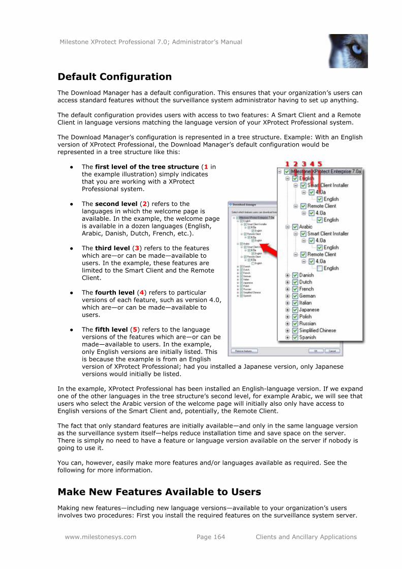
Milestone XProtect Professional 7.0; Administrator’s Manual
www.milestonesys.com Page 164 Clients and Ancillary Applications
Default Configuration
The Download Manager has a default configuration. This ensures that your organization’s users can access standard features without the surveillance system administrator having to set up anything.
The default configuration provides users with access to two features: A Smart Client and a Remote Client in language versions matching the language version of your XProtect Professional system. The Download Manager’s configuration is represented in a tree structure. Example: With an English version of XProtect Professional, the Download Manager’s default configuration would be
represented in a tree structure like this:
● The first level of the tree structure (1 in
the example illustration) simply indicates that you are working with a XProtect Professional system.
● The second level (2) refers to the languages in which the welcome page is available. In the example, the welcome page is available in a dozen languages (English, Arabic, Danish, Dutch, French, etc.).
● The third level (3) refers to the features
which are—or can be made—available to users. In the example, these features are limited to the Smart Client and the Remote Client.
● The fourth level (4) refers to particular versions of each feature, such as version 4.0,
which are—or can be made—available to users.
● The fifth level (5) refers to the language versions of the features which are—or can be made—available to users. In the example,
only English versions are initially listed. This is because the example is from an English
version of XProtect Professional; had you installed a Japanese version, only Japanese versions would initially be listed.
In the example, XProtect Professional has been installed an English-language version. If we expand one of the other languages in the tree structure’s second level, for example Arabic, we will see that
users who select the Arabic version of the welcome page will initially also only have access to English versions of the Smart Client and, potentially, the Remote Client. The fact that only standard features are initially available—and only in the same language version as the surveillance system itself—helps reduce installation time and save space on the server. There is simply no need to have a feature or language version available on the server if nobody is going to use it.
You can, however, easily make more features and/or languages available as required. See the
following for more information.
Make New Features Available to Users
Making new features—including new language versions—available to your organization’s users involves two procedures: First you install the required features on the surveillance system server.
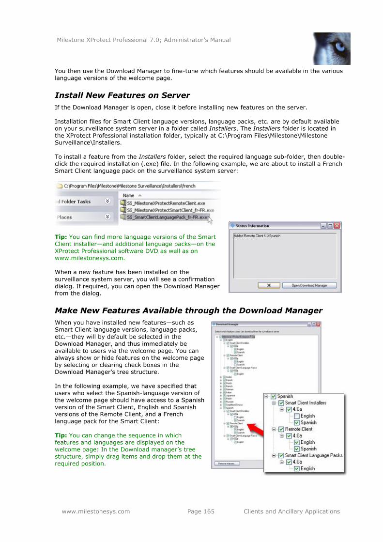
Milestone XProtect Professional 7.0; Administrator’s Manual
www.milestonesys.com Page 165 Clients and Ancillary Applications
You then use the Download Manager to fine-tune which features should be available in the various language versions of the welcome page.
Install New Features on Server
If the Download Manager is open, close it before installing new features on the server. Installation files for Smart Client language versions, language packs, etc. are by default available on your surveillance system server in a folder called Installers. The Installers folder is located in the XProtect Professional installation folder, typically at C:\Program Files\Milestone\Milestone Surveillance\Installers.
To install a feature from the Installers folder, select the required language sub-folder, then double-click the required installation (.exe) file. In the following example, we are about to install a French Smart Client language pack on the surveillance system server:
Tip: You can find more language versions of the Smart
Client installer—and additional language packs—on the XProtect Professional software DVD as well as on www.milestonesys.com. When a new feature has been installed on the
surveillance system server, you will see a confirmation dialog. If required, you can open the Download Manager from the dialog.
Make New Features Available through the Download Manager
When you have installed new features—such as Smart Client language versions, language packs,
etc.—they will by default be selected in the
Download Manager, and thus immediately be available to users via the welcome page. You can always show or hide features on the welcome page by selecting or clearing check boxes in the Download Manager’s tree structure.
In the following example, we have specified that users who select the Spanish-language version of the welcome page should have access to a Spanish version of the Smart Client, English and Spanish versions of the Remote Client, and a French language pack for the Smart Client:
Tip: You can change the sequence in which features and languages are displayed on the
welcome page: In the Download manager’s tree structure, simply drag items and drop them at the required position.
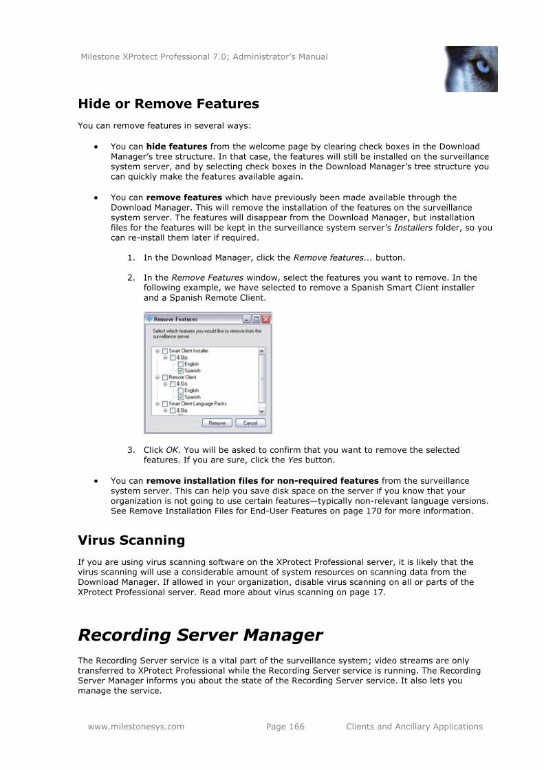
Milestone XProtect Professional 7.0; Administrator’s Manual
www.milestonesys.com Page 166 Clients and Ancillary Applications
Hide or Remove Features
You can remove features in several ways:
You can hide features from the welcome page by clearing check boxes in the Download Manager’s tree structure. In that case, the features will still be installed on the surveillance system server, and by selecting check boxes in the Download Manager’s tree structure you can quickly make the features available again.
You can remove features which have previously been made available through the
Download Manager. This will remove the installation of the features on the surveillance system server. The features will disappear from the Download Manager, but installation
files for the features will be kept in the surveillance system server’s Installers folder, so you can re-install them later if required.
1. In the Download Manager, click the Remove features... button.
2. In the Remove Features window, select the features you want to remove. In the
following example, we have selected to remove a Spanish Smart Client installer
and a Spanish Remote Client.
3. Click OK. You will be asked to confirm that you want to remove the selected features. If you are sure, click the Yes button.
You can remove installation files for non-required features from the surveillance
system server. This can help you save disk space on the server if you know that your organization is not going to use certain features—typically non-relevant language versions. See Remove Installation Files for End-User Features on page 170 for more information.
Virus Scanning
If you are using virus scanning software on the XProtect Professional server, it is likely that the virus scanning will use a considerable amount of system resources on scanning data from the Download Manager. If allowed in your organization, disable virus scanning on all or parts of the
XProtect Professional server. Read more about virus scanning on page 17.
Recording Server Manager
The Recording Server service is a vital part of the surveillance system; video streams are only transferred to XProtect Professional while the Recording Server service is running. The Recording Server Manager informs you about the state of the Recording Server service. It also lets you manage the service.
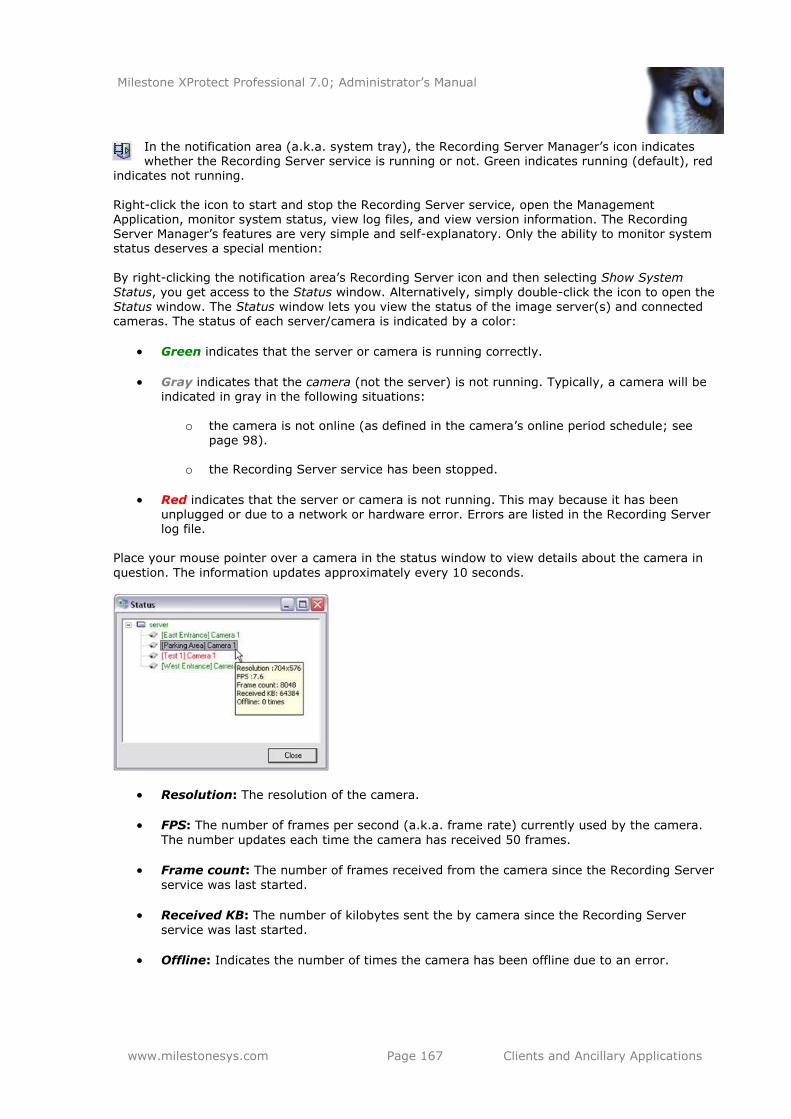
Milestone XProtect Professional 7.0; Administrator’s Manual
www.milestonesys.com Page 167 Clients and Ancillary Applications
In the notification area (a.k.a. system tray), the Recording Server Manager’s icon indicates whether the Recording Server service is running or not. Green indicates running (default), red
indicates not running.
Right-click the icon to start and stop the Recording Server service, open the Management Application, monitor system status, view log files, and view version information. The Recording Server Manager’s features are very simple and self-explanatory. Only the ability to monitor system status deserves a special mention:
By right-clicking the notification area’s Recording Server icon and then selecting Show System Status, you get access to the Status window. Alternatively, simply double-click the icon to open the
Status window. The Status window lets you view the status of the image server(s) and connected cameras. The status of each server/camera is indicated by a color:
Green indicates that the server or camera is running correctly.
Gray indicates that the camera (not the server) is not running. Typically, a camera will be indicated in gray in the following situations:
o the camera is not online (as defined in the camera’s online period schedule; see
page 98).
o the Recording Server service has been stopped.
Red indicates that the server or camera is not running. This may because it has been
unplugged or due to a network or hardware error. Errors are listed in the Recording Server log file.
Place your mouse pointer over a camera in the status window to view details about the camera in
question. The information updates approximately every 10 seconds.
Resolution: The resolution of the camera.
FPS: The number of frames per second (a.k.a. frame rate) currently used by the camera.
The number updates each time the camera has received 50 frames.
Frame count: The number of frames received from the camera since the Recording Server
service was last started.
Received KB: The number of kilobytes sent the by camera since the Recording Server
service was last started.
Offline: Indicates the number of times the camera has been offline due to an error.
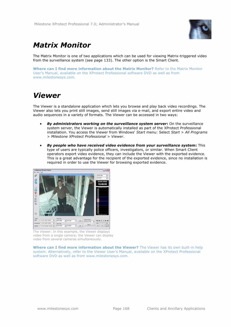
Milestone XProtect Professional 7.0; Administrator’s Manual
www.milestonesys.com Page 168 Clients and Ancillary Applications
Matrix Monitor
The Matrix Monitor is one of two applications which can be used for viewing Matrix-triggered video
from the surveillance system (see page 133). The other option is the Smart Client. Where can I find more information about the Matrix Monitor? Refer to the Matrix Monitor User’s Manual, available on the XProtect Professional software DVD as well as from www.milestonesys.com.
Viewer
The Viewer is a standalone application which lets you browse and play back video recordings. The Viewer also lets you print still images, send still images via e-mail, and export entire video and audio sequences in a variety of formats. The Viewer can be accessed in two ways:
By administrators working on the surveillance system server: On the surveillance
system server, the Viewer is automatically installed as part of the XProtect Professional installation. You access the Viewer from Windows' Start menu: Select Start > All Programs > Milestone XProtect Professional > Viewer.
By people who have received video evidence from your surveillance system: This
type of users are typically police officers, investigators, or similar. When Smart Client operators export video evidence, they can include the Viewer with the exported evidence. This is a great advantage for the recipient of the exported evidence, since no installation is required in order to use the Viewer for browsing exported evidence.
The Viewer: In this example, the Viewer displays video from a single camera; the Viewer can display video from several cameras simultaneously.
Where can I find more information about the Viewer? The Viewer has its own built-in help system. Alternatively, refer to the Viewer User’s Manual, available on the XProtect Professional software DVD as well as from www.milestonesys.com.
Milestone XProtect Professional 7.0; Administrator’s Manual
www.milestonesys.com Page 169 Removal
Removal
Remove the Entire Surveillance System
To remove the entire XProtect Professional surveillance system (that is the surveillance server software and related installation files, the video device drivers, the Download Manager, the Viewer and the Smart Client) from your server, do the following:
What happens to recordings? Your recordings will not be removed; they will remain on the server even after the server software has been removed. Likewise, the XProtect Professional configuration file will remain on the server; this allows you to reuse your configuration if you later
install XProtect Professional again.
1. Shut down all XProtect Professional components.
2. In Windows' Start menu, select Control Panel, and select Add or Remove Programs.
3. In the Add or Remove Programs window’s list of currently installed programs, select the
Milestone XProtect Professional system entry (not the Milestone XProtect Professional entry) and click the Change/Remove button.
4. The setup wizard appears; click the Next button, then the Remove button.
5. Select Remove entire surveillance system, then click Next, and complete the wizard’s
remaining steps. If you have used the PDA Client/PDA Server solution, the PDA Server software must be removed separately.
Remove Individual Components
Remove the Surveillance Server Software
To remove the XProtect Professional server software (including the Viewer, but no other surveillance system components, such as the Download Manager or the Smart Client), do the following: What happens to recordings? Your recordings will not be removed; they will remain on the server even after the server software has been removed. Likewise, the XProtect Professional configuration file will remain on the server; this allows you to reuse your configuration if you later
install XProtect Professional again.
1. Shut down all XProtect Professional components.
2. In Windows' Start menu, select Control Panel, and select Add or Remove Programs.
3. In the Add or Remove Programs window’s list of currently installed programs, select the
Milestone XProtect Professional entry (not the Milestone XProtect Professional system entry) and click the Remove button.
4. You will be asked to confirm that you want to remove XProtect Professional. If you are sure that you want to remove the software, click OK. If a Status Information window appears on
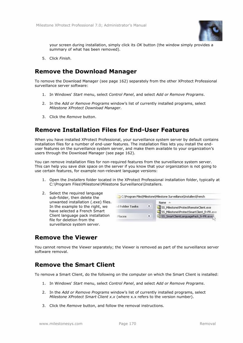
Milestone XProtect Professional 7.0; Administrator’s Manual
www.milestonesys.com Page 170 Removal
your screen during installation, simply click its OK button (the window simply provides a summary of what has been removed).
5. Click Finish.
Remove the Download Manager
To remove the Download Manager (see page 162) separately from the other XProtect Professional surveillance server software:
1. In Windows' Start menu, select Control Panel, and select Add or Remove Programs.
2. In the Add or Remove Programs window’s list of currently installed programs, select Milestone XProtect Download Manager.
3. Click the Remove button.
Remove Installation Files for End-User Features
When you have installed XProtect Professional, your surveillance system server by default contains
installation files for a number of end-user features. The installation files lets you install the end-user features on the surveillance system server, and make them available to your organization’s users through the Download Manager (see page 162).
You can remove installation files for non-required features from the surveillance system server. This can help you save disk space on the server if you know that your organization is not going to use certain features, for example non-relevant language versions:
1. Open the Installers folder located in the XProtect Professional installation folder, typically at
C:\Program Files\Milestone\Milestone Surveillance\Installers.
2. Select the required language sub-folder, then delete the unwanted installation (.exe) files.
In the example to the right, we have selected a French Smart Client language pack installation
file for deletion from the surveillance system server.
Remove the Viewer
You cannot remove the Viewer separately; the Viewer is removed as part of the surveillance server
software removal.
Remove the Smart Client
To remove a Smart Client, do the following on the computer on which the Smart Client is installed:
1. In Windows' Start menu, select Control Panel, and select Add or Remove Programs.
2. In the Add or Remove Programs window’s list of currently installed programs, select Milestone XProtect Smart Client x.x (where x.x refers to the version number).
3. Click the Remove button, and follow the removal instructions.
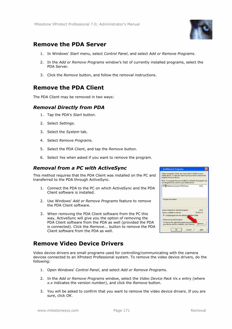
Milestone XProtect Professional 7.0; Administrator’s Manual
www.milestonesys.com Page 171 Removal
Remove the PDA Server
1. In Windows' Start menu, select Control Panel, and select Add or Remove Programs.
2. In the Add or Remove Programs window’s list of currently installed programs, select the PDA Server.
3. Click the Remove button, and follow the removal instructions.
Remove the PDA Client
The PDA Client may be removed in two ways:
Removal Directly from PDA
1. Tap the PDA’s Start button.
2. Select Settings.
3. Select the System tab.
4. Select Remove Programs.
5. Select the PDA Client, and tap the Remove button.
6. Select Yes when asked if you want to remove the program.
Removal from a PC with ActiveSync
This method requires that the PDA Client was installed on the PC and transferred to the PDA through ActiveSync.
1. Connect the PDA to the PC on which ActiveSync and the PDA Client software is installed.
2. Use Windows' Add or Remove Programs feature to remove
the PDA Client software.
3. When removing the PDA Client software from the PC this
way, ActiveSync will give you the option of removing the PDA Client software from the PDA as well (provided the PDA is connected). Click the Remove... button to remove the PDA Client software from the PDA as well.
Remove Video Device Drivers
Video device drivers are small programs used for controlling/communicating with the camera devices connected to an XProtect Professional system. To remove the video device drivers, do the following:
1. Open Windows' Control Panel, and select Add or Remove Programs.
2. In the Add or Remove Programs window, select the Video Device Pack Vx.x entry (where x.x indicates the version number), and click the Remove button.
3. You will be asked to confirm that you want to remove the video device drivers. If you are
sure, click OK.
Milestone XProtect Professional 7.0; Administrator’s Manual
www.milestonesys.com Page 172 Built-in Help System
Built-in Help System
To use XProtect Professional’s built-in help system, simply click the Help button in the Management Application’s toolbar. Alternatively, press the F1 key on your keyboard while using XProtect
Professional. The help system opens in a separate window, allowing you to easily switch between help and XProtect Professional itself. The help system in is context-sensitive. This means that when you press F1 for help while working in a particular XProtect Professional dialog, the help system automatically displays help matching that dialog.
Navigating the Built-in Help System
To navigate between the help system’s contents, simply use the help window’s tabs: Contents,
Search, Favorites and Glossary, or use the links inside the help topics.
Contents Tab: Navigate the help system based on a tree structure. Many users will be familiar with this type of navigation from, for example, Windows Explorer.
Search Tab: Search for help topics containing particular terms of interest. For example,
you can search for the term zoom and every help topic containing the term zoom will be listed in the search results. Double-clicking a help topic title in the search results list will open the required topic.
Favorites Tab: Build a list of your favorite help topics. Whenever you find a help topic of
particular interest to you, simply add the topic to your favorites list. You can then access the topic with a single click—also if you close the help window and return to it later.
Glossary Tab: Provides definitions of common surveillance and network-related terms.
Simply select a term to view a corresponding definition in the small window below the list of terms.
Help topics contain various types of links, notably so-called expanding drop-down links. Clicking
such a link will display detailed information immediately below the link itself; the content on the topic simply expands. Expanding drop-down links thus help save space. Tip: To quickly hide all texts from expanding drop-down links in a help topic, simply click the title of the topic on the help system’s Contents tab.
Printing Help Topics
To print a help topic, navigate to the required topic and click the help window’s Print button. A dialog box may ask you whether you wish to print the selected topic only or all topics under the selected heading; when this is the case, select Print the selected topic and click OK.
Tip: When printing a help topic, it will be printed as you see it on your screen. Therefore, if a topic contains expanding drop-down links, click each required drop-down link to display the text in order
for it to be included when you print. This allows you to create targeted printouts, containing exactly the amount of information you require.
Milestone XProtect Professional 7.0; Administrator’s Manual
www.milestonesys.com Page 173 Index
Index
—3— 3 GB Switching ................................................................................................................ 145
—A— Active Directory .......................................................................................................... 47, 123
ActiveSync ...................................................................................................................... 159
Add Hardware Devices Wizard, Advanced Method .................................................................. 29
Add Hardware Devices Wizard, Express Method ..................................................................... 27
Add Hardware Devices Wizard, Import from CSV File Method .................................................. 35
Add Hardware Devices Wizard, Manual Method ...................................................................... 32
Adjust Motion Detection Wizard ........................................................................................... 45
Administrator .................................................................................................................. 122
Advanced Method, Add Hardware Devices Wizard .................................................................. 29
Alert and Generic Event Port ............................................................................................. 108
Apply/Save Configuration Changes ....................................................................................... 24
Archiving .......................................................................................................................... 85
Archiving Path for New Cameras, Default ............................................................................ 136
Archiving, Scheduling of ..................................................................................................... 97
Audio .......................................................................................................................... 70, 93
Audio Recording, Camera Properties ..................................................................................... 66
Audio Selection, Camera Properties ...................................................................................... 65
Audit Log ................................................................................................................. 128, 130
—B—
Backup, Archived Recordings ............................................................................................... 88
Backup, Surveillance System Configuration .............................................................19, 138, 143
Basic User .................................................................................................................. 47, 122
Buffer, Pre-/Post-recording ............................................................................................ 61, 71
—C— Cameras ........................................................................................................................... 57
Cameras, Add .................................................................................................................... 26
Cameras, Replace .............................................................................................................. 48
Central ........................................................................................................................... 132
Client Access to Surveillance System .................................................................................. 120
Clients ............................................................................................................................ 150
Clone ............................................................................................................................. 138
Comma-separated Values ............................................................................................ 35, 139
Configuration Path ........................................................................................................... 136
Configure User Access Wizard .............................................................................................. 46
Configure Video and Recording Wizard .................................................................................. 38
Milestone XProtect Professional 7.0; Administrator’s Manual
www.milestonesys.com Page 174 Index
Corrupt Database, Repair .................................................................................................... 72
CPU, Minimum Requirements............................................................................................... 13
CSV File ..................................................................................................................... 35, 139
—D—
Database Resizing .............................................................................................................. 83
Database, Inherit/Delete/Leave Existing ............................................................................... 50
Database, Protect from Corruption ..................................................................................... 147
Database, Repair Corrupt .................................................................................................... 72
Daylight Saving Time ....................................................................................................... 144
Default Archiving Path for New Cameras ............................................................................. 136
Default File Paths ............................................................................................................. 136
Default Microphone and Speaker ..................................................................................... 65, 70
Default Recording Path for New Cameras ............................................................................ 136
Device Discovery ............................................................................................................... 27
Device Drivers ................................................................................................................. 149
Device License Key............................................................................................................. 52
Device Pack ..................................................................................................................... 149
DirectX ............................................................................................................................. 13
DLK .................................................................................................................................. 52
Download Manager ........................................................................................................... 161
Driver IDs ....................................................................................................................... 179
Drivers ........................................................................................................................... 149
DST................................................................................................................................ 144
Dynamic Archiving ........................................................................................................ 86, 91
Dynamic Path Selection, Camera Properties .......................................................................... 59
—E— E-mail Notification, Scheduling Property for Cameras ........................................................... 100
E-mail Notifications ................................................................................................... 100, 103
Event Log ................................................................................................................ 128, 129
Event Notification, Camera Properties ................................................................................... 73
Events ............................................................................................................................ 107
Events, Configure Ports and Polling Interval for ................................................................... 108
Export/Import Surveillance System Configuration ................................................................ 138
Express Method, Add Hardware Devices Wizard ..................................................................... 27
—F— Fisheye ........................................................................................................................ 55, 76
Fisheye, Camera Properties ................................................................................................. 76
Fisheye, Hardware Device Properties .................................................................................... 55
Frame Rate – MJPEG, Camera Properties .............................................................................. 62
Frame Rate – MPEG, Camera Properties ................................................................................ 64
Frame Rate, Camera Properties ........................................................................................... 68
FTP Event Port ................................................................................................................. 108
Milestone XProtect Professional 7.0; Administrator’s Manual
www.milestonesys.com Page 175 Index
—G— Generic Events ......................................................................................................... 107, 111
Getting Started .................................................................................................................. 21
Graphics Adapter, Minimum Requirements ............................................................................ 13
Group, User .................................................................................................................... 124
—H—
Hard Disk, Minimum Requirements ....................................................................................... 13
Hardware Device Drivers................................................................................................... 149
Hardware Devices .............................................................................................................. 53
Hardware Devices, Add ....................................................................................................... 26
Hardware Devices, Replace ................................................................................................. 48
Hardware Driver IDs......................................................................................................... 179
Hardware Input ............................................................................................................... 107
Hardware Input Events .............................................................................................. 107, 109
Hardware Output ...................................................................................................... 107, 117
Hardware Output on Event ................................................................................................ 118
Help System, Built-in ........................................................................................................ 171
—I— IIS ................................................................................................................................... 13
Image Import Service ....................................................................................................... 119
Image Import Service Log .......................................................................................... 128, 129
Image Server Service ....................................................................................................... 119
Image Server Service Log .......................................................................................... 128, 129
Import Changes to Surveillance System Configuration .......................................................... 139
Import DLKs ...................................................................................................................... 52
Import from CSV File Method, Add Hardware Devices Wizard .................................................. 35
Import/Export Surveillance System Configuration ................................................................ 138
Inherit/Delete/Leave Existing Database ................................................................................ 50
Input .............................................................................................................................. 107
Installation ........................................................................................................................ 18
Installation, Upgrade from Previous Version .......................................................................... 19
Integrity Checks, Log ....................................................................................................... 130
Internet Information Services .............................................................................................. 13
IPIX .................................................................................................................... See Fisheye
—K—
Keyframe Only, MPEG Recording ..................................................................................... 64, 69
—L—
Language Support & XML, Properties for Client Access to Surveillance System ......................... 121
Licenses ............................................................................................................................ 52
Live Video, View in Management Application .......................................................................... 83
Local IP Ranges ............................................................................................................... 121
Log Check Service ............................................................................................................ 119
Milestone XProtect Professional 7.0; Administrator’s Manual
www.milestonesys.com Page 176 Index
Logging .......................................................................................................................... 128
—M— Management Application ..................................................................................................... 24
Management Application Behavior, Change/Reset .................................................................. 25
Management Application Log ...................................................................................... 128, 129
Management Application, View Live Video in .......................................................................... 83
Manual Events .......................................................................................................... 107, 110
Manual Method, Add Hardware Devices Wizard ...................................................................... 32
Manual Recording, Camera Properties ................................................................................... 61
Matrix ............................................................................................................................. 133
Matrix Monitor ............................................................................................................ 15, 167
Microphone, Default ...................................................................................................... 65, 70
Microphones, Configuration ................................................................................................. 93
MJPEG ................................................................................................................... 62, 68, 99
Motion Detection ........................................................................................................... 45, 74
Motion Detection & Exclude Regions, Camera Properties ......................................................... 74
MPEG .......................................................................................................................... 64, 69
—N— Name & Video Channels, Hardware Device Properties ............................................................. 53
Network, Device Type & License, Hardware Device Properties .................................................. 53
Network, Minimum Requirements ......................................................................................... 13
—O—
Online Period, Scheduling Property for Cameras ..................................................................... 98
Operating System, Minimum Requirements ........................................................................... 13
Output ..................................................................................................................... 107, 117
Output Control on Event ................................................................................................... 118
Output, Camera Properties .................................................................................................. 73
—P—
Pan/Tilt/Zoom ........................................................................................................... See PTZ
Password Protection, Management Application ....................................................................... 24
Paths, Default .................................................................................................................. 136
Patrolling, PTZ ............................................................................................................ 79, 101
PDA Client ...........................................................................................................15, 150, 159
PDA Server ................................................................................................................ 14, 155
Plug-in Information .......................................................................................................... 136
Polling Interval ................................................................................................................ 108
Port Numbers, Important .................................................................................................... 16
Post-alarm Images ........................................................................................................... 119
Post-recording .............................................................................................................. 61, 71
Pre-alarm Images ..................................................................................................... 119, 128
Pre-recording ............................................................................................................... 61, 71
Preset Positions, PTZ .......................................................................................................... 77
Milestone XProtect Professional 7.0; Administrator’s Manual
www.milestonesys.com Page 177 Index
PTZ ................................................................................................................ 54, 77, 79, 101
PTZ Device, Hardware Device Properties ............................................................................... 54
PTZ on Event, Camera Properties ......................................................................................... 82
PTZ Patrolling, Camera Properties ........................................................................................ 79
PTZ Patrolling, Scheduling Property for Cameras .................................................................. 101
PTZ Preset Positions, Camera Properties ............................................................................... 77
PTZ Scanning .................................................................................................................... 81
PTZ Type .......................................................................................................................... 77
—R— RAM, Minimum Requirements .............................................................................................. 13
Recording & Archiving Paths, Camera Properties ............................................................... 57, 71
Recording Path for New Cameras, Default ........................................................................... 136
Recording Server Manager ................................................................................................ 165
Recording Server Service .................................................................................................. 119
Recording Server Service Log ..................................................................................... 128, 129
Recording Settings, Camera Properties ................................................................................. 70
Recordings ........................................................................................................................ 57
Remote Client ......................................................................................................14, 150, 154
Removal ......................................................................................................................... 168
Replace Hardware Device Wizard ......................................................................................... 48
Reset/Change Management Application Behavior ................................................................... 25
Restart Services............................................................................................................... 119
Restore Points ................................................................................................................. 137
Retention Time .................................................................................................................. 72
Rights, User .................................................................................................................... 124
Running Out of Disk Space .................................................................................................. 88
—S— Save/Apply Configuration Changes ....................................................................................... 24
Scheduling ........................................................................................................................ 95
Server Access .................................................................................................................. 120
Services .......................................................................................................................... 119
SLC .................................................................................................................................. 52
Smart Client ........................................................................................................13, 150, 152
SMS Notification, Scheduling Property for Cameras .............................................................. 100
SMS Notifications ............................................................................................................. 105
SMTP Event Port .............................................................................................................. 108
SMTP Server ................................................................................................................... 104
Software License Code ........................................................................................................ 52
Software, Minimum Requirements ........................................................................................ 13
Space, Monitor Use of ......................................................................................................... 83
Speaker, Default ........................................................................................................... 65, 70
Milestone XProtect Professional 7.0; Administrator’s Manual
www.milestonesys.com Page 178 Index
Speakers, Configuration ...................................................................................................... 94
Speedup ................................................................................................................ 63, 68, 99
Speedup, Scheduling Property for MJPEG Cameras ................................................................. 99
SSL ................................................................................................................................ 104
Start Services .................................................................................................................. 119
Static Archiving ................................................................................................................. 91
Stop Services .................................................................................................................. 119
Storage Information, Camera Properties ............................................................................... 67
Storage Space, Monitor Use of ............................................................................................. 83
Summer Time .................................................................................................................. 144
System Requirements, Minimum .......................................................................................... 13
—T— TCP Data Package, Event Triggered by ............................................................................... 111
Text Message, Mobile Phone ..........................................................................................See SMS
Time Server ...................................................................................................................... 17
Timer Events ............................................................................................................ 107, 116
TLS ................................................................................................................................ 104
—U—
UDP Data Package, Event Triggered by ............................................................................... 111
Uninstallation .................................................................................................................. 168
Upgrade from Previous Version ............................................................................................ 19
UPS ................................................................................................................................ 147
User Rights ..................................................................................................................... 124
Users ........................................................................................................................ 46, 122
Users, Groups of .............................................................................................................. 124
—V— Version Information ......................................................................................................... 136
Video Device Drivers ........................................................................................................ 149
Video Encoder ........................................................................................................ 26, 53, 54
Video Recording, Camera Properties ..................................................................................... 60
Video Server ................................................................................................... See Video Encoder
Video, Camera Properties .................................................................................................... 69
Video, View Live in Management Application .......................................................................... 83
Viewer ............................................................................................................................ 167
Viewer Export Log ............................................................................................................ 128
Virus Scanning .................................................................................................................. 17
VMD ............................................................................................................................ 45, 74
—W—
Windows User ............................................................................................................. 47, 123
Wizards ............................................................................................................................ 26
—X— XProtect Central .............................................................................................................. 132

Milestone XProtect Professional 7.0; Administrator’s Manual
www.milestonesys.com Page 179 Index
Milestone XProtect Professional 7.0; Administrator’s Manual
www.milestonesys.com Page 180 Appendix: Hardware Driver IDs
Appendix: Hardware Driver IDs
If using the Add Hardware Devices Wizard’s Import from CSV File option (see page 35), you must—if cameras and server are offline—specify a HardwareDriverID for each hardware device you want
to add. In the following, IDs for all hardware devices supported at the time of release of this version of XProtect Professional are listed. The list is sorted alphabetically by device, with the corresponding ID at the end of each line.
Example: ACTi ACD-2100 105 indicates that you should use 105 as the ID if adding an ACTi ACD-2100 hardware device.
This list is for guidance only; IDs are subject to change without notice. More devices may be supported by the time you read this, as new versions of video device drivers—so-called Device Packs—are released at regular intervals. To view a current list of IDs, view the release notes for the Device Pack used in your organization. Alternatively visit www.milestonesys.com for the latest information. 360 Vision IP Dome 320
ACTi ACD-2100 105 ACTi ACD-2200 173 ACTi ACD-2300 152 ACTi ACD-2400 228
ACTi ACM-1011 105 ACTi ACM-1100 series 105
ACTi ACM-1230 series 105 ACTi ACM-1310 series 105 ACTi ACM-1430 series 105 ACTi ACM-1511 105 ACTi ACM-3001 105 ACTi ACM-3011 105 ACTi ACM-3100 series 105
ACTi ACM-3210 series 105 ACTi ACM-3300 series 105 ACTi ACM-3400 series 105 ACTi ACM-3511 105 ACTi ACM-3701 105 ACTi ACM-4000 series 105
ACTi ACM-4100 series 105
ACTi ACM-4200 series 105 ACTi ACM-5001 105 ACTi ACM-5600 series 105 ACTi ACM-5711 105 ACTi ACM-7400 series 105 ACTi ACM-7511 105
ACTi ACM-8100 series 105 ACTi ACM-8200 series 105 ACTi CAM-5100H 105 ACTi CAM-5100M 105 ACTi CAM-5100S 105 ACTi CAM-5120 105 ACTi CAM-5130 105
ACTi CAM-5140 105 ACTi CAM-5150 105 ACTi CAM-5200 series 105 ACTi CAM-5220 series 105 ACTi CAM-5300 series 105 ACTi CAM-5320 series 105 ACTi CAM-5500 105
Milestone XProtect Professional 7.0; Administrator’s Manual
www.milestonesys.com Page 181 Appendix: Hardware Driver IDs
ACTi CAM-5520 105 ACTi CAM-6100 105 ACTi CAM-6110 105
ACTi CAM-6120 105 ACTi CAM-6200 105 ACTi CAM-6210 105 ACTi CAM-6220 105 ACTi CAM-6230 105 ACTi CAM-6500 105
ACTi CAM-6510 105 ACTi CAM-6520 105
ACTi CAM-6600 105 ACTi CAM-6610 105 ACTi CAM-6620 105 ACTi CAM-6630 105 ACTi CAM-7100-series 105
ACTi CAM-7200-series 105 ACTi CAM-7300-series 105 ACTi SED-2100R 105 ACTi SED-2100S 105 ACTi SED-2120/2120T 105 ACTi SED-2130 105 ACTi SED-2140 105
ACTi SED-2200 105 ACTi SED-2300Q 117
ACTi SED-2310Q 117 ACTi SED-2320Q 117 ACTi SED-2400 105 ACTi SED-2410 141
ACTi SED-2420 141 ACTi SED-2600 152 ACTi SED-2610 152 ACTi TCM-4301 327 ACTi TCM-5311 334 Adam 6050 129 Adam 6060 108
Adam 6066 108 AgileMesh 100 145 American Dynamics VideoEdge Dome 157
American Dynamics VideoEdge IP Box Camera 157 APPRO LC-7224 series 156 APPRO LC-7226 series 157 Apro Technology H1000 series 255
Arecont AV1300 140 Arecont AV1305 140 Arecont AV1355 140 Arecont AV2100 140 Arecont AV2105 140 Arecont AV2155 140
Arecont AV3100 140 Arecont AV3105 140 Arecont AV3130 140 Arecont AV3155 140
Arecont AV5100 140 Arecont AV5105 140 Arecont AV5155 140
Arecont AV8180 154 Arecont AV8185 154 Arecont AV8360 154 Arecont AV8365 154
Milestone XProtect Professional 7.0; Administrator’s Manual
www.milestonesys.com Page 182 Appendix: Hardware Driver IDs
AXIS 200+ 1 AXIS 205 15 AXIS 206 19
AXIS 206M 19 AXIS 206W 19 AXIS 207 18 AXIS 207MW 18 AXIS 207W 18 AXIS 209FD 168
AXIS 209MFD 168 AXIS 210 18
AXIS 210A 18 AXIS 211 18 AXIS 211A 18 AXIS 211M 18 AXIS 211W 18
AXIS 212 PTZ 138 AXIS 213 PTZ 22 AXIS 214 PTZ 123 AXIS 215 PTZ 123 AXIS 215 PTZ-E 123 AXIS 216FD 122 AXIS 216MFD 122
AXIS 221 25 AXIS 223M 153
AXIS 225FD 25 AXIS 231D 23 AXIS 231D+ 23 AXIS 232D 23
AXIS 232D+ 23 AXIS 233D 23 AXIS 240 2 AXIS 240Q 16 AXIS 241Q 16 AXIS 241QA 16 AXIS 241S 17
AXIS 241SA 17 AXIS 242S IV 17 AXIS 243Q 160
AXIS 243SA 17 AXIS 247S 172 AXIS 282 130 AXIS 2100 5
AXIS 2110 5 AXIS 2120 6 AXIS 2130 12 AXIS 2400 OSYS 3 AXIS 2400 Linux 8 AXIS 2400+ 8
AXIS 2401 OSYS 4 AXIS 2401 Linux 11 AXIS 2401+ 11 AXIS 2411 14
AXIS 2420 10 AXIS 2420 10 AXIS M1011 283
AXIS M1031 284 AXIS M3011 285 AXIS M3014 342 AXIS M7001 286
Milestone XProtect Professional 7.0; Administrator’s Manual
www.milestonesys.com Page 183 Appendix: Hardware Driver IDs
AXIS P1311 288 AXIS P3301 246 AXIS P3343 339
AXIS P3344 339 AXIS Q1755 278 AXIS Q6032 335 AXIS Q7401 256 AXIS Q7404 337 AXIS Q7406 268
Barix Barionet 272 Basler BIP-640c 242
Basler BIP-640c-dn 242 Basler BIP-1000c 242 Basler BIP-1000c-dn 242 Basler BIP-1300c 242 Basler BIP-1300c-dn 242
Basler BIP-1600c 242 Basler BIP-1600c-dn 242 Baxall X-Stream 91 Bosch Dinion NWC-0455-10P 133 Bosch Dinion NWC-0495-10P 133 Bosch FlexiDome NWD-0455 133 Bosch FlexiDome NWD-0495 133
Bosch VideoJet X10 253 Bosch VideoJet X20 253
Bosch VideoJet X40 253 Bosch VIP X1 127 Bosch VIP X2 132 Bosch VIP X1600 162
Bosch VG4 Series 190 Canon VB-C10 31 Canon VB-C50FSi 212 Canon VB-C50i 212 Canon VB-C50iR 212 Canon VB-C60 276 Canon VB-C300 174
Canon VB-C500 330 CBC Ganz ZN-D2024 207 CBC Ganz ZN-PT304L 179
CBC Ganz ZN-PT304WL 179 Checkview 9128702 275 Cisco IPC-2500 322 Cisco IPC-4300 322
Cisco IPC-4500 322 Convision S1 21 Convision V100 21 Convision V200 20 Convision V6xx 7 Convision V7xx 7
D-Link DCS1000/1000W 55 D-Link DCS-2000 101 D-Link DCS-2100+/2100/2100G 101 D-Link DCS-3220/3220G 118
D-Link DCS-5300 99 D-Link DCS-5300G 99 D-Link DCS-6620/6620G 116
Darim Vision PVE400 298 Digimerge DNB6320 177 Digimerge DND7220 177 Digimerge DNP5220E 177
Milestone XProtect Professional 7.0; Administrator’s Manual
www.milestonesys.com Page 184 Appendix: Hardware Driver IDs
Digimerge DNP5320E 177 Digimerge DNS1010 177 Digimerge DNZ-9320W 244
DirectShow camera 214 Discrete DIV2300 188 DvTel DVT-7101 262 DvTel DVT-7608 261 DvTel DVT-9460 514 DvTel DVT-9540DW 514
Dynacolor Diva Standard 296 Dynacolor Diva Zoom 282
Dynacolor Diva Mini 297 Etrovision EV3130 236 Etrovision EV3131 237 Etrovision EV3131A 237 Etrovision EV3830 238
Etrovision EV6130 239 Etrovision EV6230 240 Etrovision EV6530 240 Extreme CCTV EX7 103 Extreme CCTV EX30 103 Extreme CCTV EX36 103 Extreme CCTV EX80 103
Extreme CCTV EX82 103 Extreme CCTV EX85 140
Extreme CCTV REG-L1-IP 103 Eyeview CMI-110 245 Eyeview CMI-H230 245 Eyeview CMI-H260 245
Eyeview EYENET-250A 245 Eyeview GPOWER IP Basement 245 Eyeview IPM-100 245 Eyeview IPM-150 245 Eyeview IPM-300 245 Eyeview IPM-500 245 Eyeview IPR-220 245
Eyeview IPR-330 245 Eyeview IPR-6000 245 Eyeview IPR-6600 245
Eyeview IPS-110 245 Eyeview IPS-220 245 Eyeview IPS-300 245 Eyeview IPS-330 245
Eyeview IPS-400 245 Eyeview IPS-500 245 Eyeview IPS-600 245 Eyeview IPS-800 245 Eyeview IPS-830 245 Eyeview IPS-900 245
FLIR 241S 95 GE Security GEC-IP2B 225 GE Security GEC-IP2B-C 225 GE Security GEC-IP2B-P 225
GE Security GEC-IP2D 225 GE Security GEC-IP2D-C 225 GE Security GEC-IP2D-P 225
GE Security GEC-IP2VD 225 GE Security GEC-IP2VD-C 225 GE Security GEC-IP2VD-P 225 GE Security GEC-IP2VD-DN 225
Milestone XProtect Professional 7.0; Administrator’s Manual
www.milestonesys.com Page 185 Appendix: Hardware Driver IDs
GE Security GEC-IP2VD-DNC 225 GE Security GEC-IP2VD-DNP 225 Grandeye Halocam IPC 249
Grandeye Halocam IPW 249 HikVision DS6101 277 HikVision DS6104 273 Hitron HECMC4V4C4 217 Hitron HEV0104 223 Hitron HEV0407 224
Hitron HNCA-811-NZ1 222 Hitron HNCB-811NZ1 219
Hitron HNCB-F1SN 218 Hitron HNCG-F1SAW0S4 220 Hitron HNCV-811PZ0S4 221 Hitron HWD-12SMP 187 Hunt HLC-81I 201
Hunt HLC-81M 201 Hunt HLC-83M 202 Hunt HLC-83V 203 Hunt HLT-86F 198 Hunt HLT-87Z 209 Hunt HLV-1CI 200 Hunt HLV-1CM 200
Hunt HVT-01HT 199 Hunt HWS-01HD 204
Hunt HWS-04HD/W 205 ICanServer 510 257 ICanServer 512 257 ICanServer 540 259
ICanView 220 258 ICanView 222 258 ICanView 230 258 ICanView 232 258 ICanView 240 257 ICanView 250 257 ICanView 260 258
ICanView 270 257 ICanView 280 258 ICanView 290 257
Infinova V1700N-C series NetDome 119 Infinova V1700N-L series NetDome 137 Intellinet MNC-L10/550710 104
ioibox series 400 ioibox series 401 ioicam series 400 IPIX IS2000/CVD2000/CVN2000 57 IPIX CVD3000 57 Ipx DDK-1000 157
Ipx DDK-1500 157 Ipx DDK-1500D 157 Ipx VE-3500 157 IQEye101 83
IQEye300 series 83 IQEye 4 series 83 IQEye501 83
IQEye510 83 IQEye 511 83 IQEye600 series 83 IQEye700 series 83
Milestone XProtect Professional 7.0; Administrator’s Manual
www.milestonesys.com Page 186 Appendix: Hardware Driver IDs
IQEye800 Sentinel series 83 IQEye Alliance series 83 Johnson Controls DVN5008 293
JVC VN-A1U 43 JVC VN-C10U 44 JVC VN-C20U 126 JVC VN-C30U 42 JVC VN-C3WU 40 JVC VN-C205 169
JVC VN-C215 146 JVC VN-C625U 45
JVC VN-C655U 45 JVC VN-E4/-E4E /-E4U 121 JVC VN-V25 185 JVC VN-V26 185 JVC VN-V225 185
JVC VN-V685 196 JVC VN-V686/V686B 196 JVC VN-V686WPC 196 JVC VN-X35 235 JVC VN-X235 235 Lenel ICT-220 345 Lenel ICT-230 345
Lenel ICT-250 346 Lenel ICT-510 345
Lenel LC-330FDX 345 Linudix LWS800 511 Linudix LWS820 512 Linudix LWS840 511
Lumenera LE165 84 Lumenera LE175 84 Lumenera LE256 84 Lumenera LE259 84 Lumenera LE275 84 Lumenera LE375 84 Lumenera LE575 84
Mobotix D10 86 Mobotix D12 86 Mobotix D22M 86
Mobotix M1 86 Mobotix M10 86 Mobotix M12 86 Mobotix M22M 86
Mobotix Q22 260 Mobotix Q24 328 Optelecom Siqura BC-2x series 281 Optelecom Siqura C-50 269 Optelecom Siqura C-54 289 Optelecom Siqura C-60 321
Optelecom Siqura FD-2x series 281 Optelecom Siqura S-50 269 Optelecom Siqura S-54 289 Optelecom Siqura S-60 321
Optelecom Siqura V-30 295 Panasonic BB-HCE481 series 24 Panasonic BB-HCM311 series 24
Panasonic BB-HCM331 series 24 Panasonic BB-HCM371A 24 Panasonic BB-HCM381 series 24 Panasonic BB-HCM403 24
Milestone XProtect Professional 7.0; Administrator’s Manual
www.milestonesys.com Page 187 Appendix: Hardware Driver IDs
Panasonic BB-HCM511 180 Panasonic BB-HCM515 180 Panasonic BB-HCM527 180
Panasonic BB-HCM531 180 Panasonic BB-HCM547 180 Panasonic BB-HCM580 180 Panasonic BB-HCM581 180 Panasonic BB-HCS301 24 Panasonic BL –C1 series 24
Panasonic BL-C10 series 24 Panasonic BL-C20 series 24
Panasonic BL-C30 series 24 Panasonic BL-C111 182 Panasonic BL-C131 182 Panasonic KX-HCM8 63 Panasonic KX-HCM10 series 63
Panasonic KX-HCM110A series 24 Panasonic KX-HCM230 series 63 Panasonic KX-HCM250 series 63 Panasonic KX-HCM270 series 63 Panasonic KX-HCM280 series (except 280A) 63 Panasonic KX-HCM280A 24 Panasonic WJ-NT104 60
Panasonic WJ-NT304 183 Panasonic WV- NF284 120
Panasonic WV-NF302 211 Panasonic WV-NP240/WV-NP244 120 Panasonic WV-NP304 211 Panasonic WV-NP472 61
Panasonic WV-NP502 351 Panasonic WV-NP1000/WV-NP1004 120 Panasonic WV-NS202 143 Panasonic WV-NS320 series 64 Pansonic WV-NS950 197 Pansonic WV-NS954 197 Panasonic WV-NW470 85
Panasonic WV-NW484 175 Panasonic WV-NW502 351 Pansonic WV-NW960 197
Pansonic WV-NW964 197 Pentax Versacam IC-4 50 Pelco Camclosure IP series 149 Pelco Endura Net5301T 144
Pelco Endura Net5308T 166 Pelco Endura Net5316T 167 Pelco IP3701 176 Pelco NET300 208 Pelco NET350 208 Pelco Spectra IV-IP 213
Pelco SpectraMini IV-IP 213 Philips NETSVR-1 93 Philips NETSVR-6 92 Pixord 120 72
Pixord 126 75 Pixord 200 73 Pixord 201 73
Pixord 205 77 Pixord 207 77 Pixord 24X 74 Pixord 261 78
Milestone XProtect Professional 7.0; Administrator’s Manual
www.milestonesys.com Page 188 Appendix: Hardware Driver IDs
Pixord 1000 75 Pixord 400/400W 151 Pixord 461 148
Pixord 463 148 Pixord 1401/1401W 136 Pixord 2000 76 Pixord 4000 151 Polar Industries zPan100 501 Provideo SD-606W 279
Provideo SD-705VPRO-1 280 Samsung SCC-C6475 131
Samsung SHR-2040 165 Samsung SNC-B2315 227 Samsung SNC-B5395 248 Samsung SNC-C6225 325 Samsung SNC-C7225 325
Samsung SNC-C7478 299 Samsung SNC-M300 226 Samsung SNT-1010 147 Samsung Techwin SNC550 191 Samsung Techwin SNC570 291 Samsung Techwin SND460V 329 Samsung Techwin SND560 292
Samsung Techwin SNP1000/SNP1000A 195 Samsung Techwin SNP3300/SNP3300A 194
Samsung Techwin SNS100 192 Samsung Techwin SNS400 193 Sanyo VCC-400N 206 Sanyo VCC-9500 206
Sanyo VCC-9500P 206 Sanyo VCC-9600 206 Sanyo VCC-9600P 206 Sanyo VCC-9700 206 Sanyo VCC-9700P 206 Sanyo VCC-9800 206 Sanyo VCC-9800P 206
Sanyo VCC-HD4000 206 Sanyo VCC-HD4000P 206 Sanyo VCC-HDN1(S) 206
Sanyo VCC-N6584 206 Sanyo VCC-N6695P 206 Sanyo VCC-WB2000/VCC-WB4000 56 Sanyo VCC-P450 206
Sanyo VCC-P450NA 206 Sanyo VCC-P470 206 Sanyo VCC-P470NA 206 Sanyo VCC-P7574 142 Sanyo VCC-P7575P 142 Sanyo VCC-P9574 142
Sanyo VCC-P9574N 142 Sanyo VCC-P9575P 142 Sanyo VCC-PN9575P 142 Sanyo VCC-PT490 206
Sanyo VCC-PT490NA 206 Sanyo VCC-PT500 206 Sanyo VCC-PT500NA 206
Sanyo VCC-XZ200 206 Sanyo VCC-XZ200P 206 Sanyo VCC-XZ600P 206 Sanyo VCC-XZN600P 206
Milestone XProtect Professional 7.0; Administrator’s Manual
www.milestonesys.com Page 189 Appendix: Hardware Driver IDs
Sanyo VCC-ZM600P 206 Sanyo VCC-ZMN600P 206 Sanyo VDC-DP7584 142
Sanyo VDC-DP7585P 142 Sanyo VDC-DP9584 142 Sanyo VDC-DP9584N 142 Sanyo VDC-DP9585 142 Sanyo VDC-DPN9585P 142 Sanyo VSP-SV2000 56
Siemens CCIC1345 252 Siemens CCIS1345 252
Siemens CCIS1345-DN 252 Siemens CCIW1345 252 Sony SNC-CS3 54 Sony SNC-CS10 88 Sony SNC-CS11 88
Sony SNC-CS20 216 Sony SNC-CS50 125 Sony SNC-CM120 215 Sony SNC-DF40 88 Sony SNC-DF50 178 Sony SNC-DF70 88 Sony SNC-DF80 178
Sony SNC-DF85 178 Sony SNC-DM110 215
Sony SNC-DM160 215 Sony SNC-DS10 216 Sony SNC-DS60 216 Sony SNC-M1/SNC-M1W 102
Sony SNC-M3/SNC-M3W 102 Sony SNC-P1 88 Sony SNC-P5 98 Sony SNC-RX530 124 Sony SNC-RX550 124 Sony SNC-RX570 124 Sony SNC-RZ25 89
Sony SNC-RZ30 52 Sony SNC-RZ30/2 52 Sony SNC-RZ50 128
Sony SNC-Z20 53 Sony SNC-VL10 51 Sony SNT-V304 9 Sony SNT-V501 82
Sony SNT-V704 113 Speco Technologies SIPB1/SIPB2 501 Speco Technologies SIPB3/SIPB4 501 Speco Technologies SIPMPT5 501 Speco Technologies SIPSD10X 501 StarDot NetCam XL 186
StarDot NetCam SC 5 MP 186 Toshiba IK-WB01A 115 Toshiba IK-WB02A 114 Toshiba IK-WB15A 115
Toshiba IK-WB11A 59 Toshiba IK-WB21A 115 Toshiba IK-WD01A 508
Toshiba IK-WR01A 114 Toshiba Teli CI7010 181 Toshiba Teli CI8110D 263 Toshiba Teli CI8210D 250
Milestone XProtect Professional 7.0; Administrator’s Manual
www.milestonesys.com Page 190 Appendix: Hardware Driver IDs
Toshiba Teli EJ7000 170 UDP IPC1100 231 UDP IPC3100 231
UDP IPC3500 231 UDP IPC4100 229 UDP IPC4500 229 UDP NVE12K 230 UDP NVE40K 230 UDP NVE100 232
UDP NVE1000 233 UDP NVE2000 234
UDP NVE4000 230 Universal driver 400 Universal driver 16 Chnl. 401 Vantage VIPC1100E 501 Vantage VIPC1311EP 501
Vantage VIPC1431EP 501 Vantage VIPC3100E 501 Vantage VIPC3211EP 501 Vantage VIPC3311EP 501 Vantage VIPC5300 501 Vantage VIPC5320 501 Vantage VIPC6510F 501
Vantage VIPC6610F 501 Vantage VIPC7100 series 501
Vantage VIPC7200 series 501 Vantage VIPC7300 series 501 Vantage VIPS2120 501 Vantage VIPS2310Q 501
Vantage VIPS2410 506 VCS VideoJet 10 96 VCS VideoJet 400 94 VCS VIP 10 96 Veo Observer XT 32 Verint Nextiva S1700e 103 Verint Nextiva S1704e 135
Verint Nextiva S1708e 111 Verint Nextiva S1712e 163 Verint Nextiva S1724e 164
Verint Nextiva S1900e 103 Verint Nextiva S1950e 103 Verint Nextiva S1970e 103 Verint Nextiva S2600e/S2610e 103
Verint Nextiva S2700e 103 Videology 20N758 184 Videology 21N758 184 Videology Server Board 189 Vivotek FD6100 series 109 Vivotek FD7131 331
Vivotek FD7132 331 Vivotek FD7141 331 Vivotek FD7141V 331 Vivotek IP2121 58
Vivotek IP2122 58 Vivotek IP3121 97 Vivotek IP3122 97
Vivotek IP3135 97 Vivotek IP6124 109 Vivotek IP7130 333 Vivotek IP7131 155
Milestone XProtect Professional 7.0; Administrator’s Manual
www.milestonesys.com Page 191 Appendix: Hardware Driver IDs
Vivotek IP7133 348 Vivotek IP7134 348 Vivotek IP7135 155
Vivotek IP7137 155 Vivotek IP7138 331 Vivotek IP7139 331 Vivotek IP7142 251 Vivotek IP7151 251 Vivotek IP7152 251
Vivotek IP7153 251 Vivotek IP7154 251
Vivotek IP7160 251 Vivotek IP7161 251 Vivotek IP7251 347 Vivotek IP7330 333 Vivotek IZ7151 349
Vivotek PT3124 107 Vivotek PT7135 158 Vivotek PT7137 158 Vivotek PZ6122 110 Vivotek PZ7111 332 Vivotek PZ7112 332 Vivotek PZ7121 332
Vivotek PZ7122 332 Vivotek PZ7131 332
Vivotek PZ7132 332 Vivotek PZ7151 349 Vivotek PZ7152 349 Vivotek SD6122V 110
Vivotek SD7151 338 Vivotek SD7313 338 Vivotek SD7323 338 Vivotek VS2101 58 Vivotek VS2402 68 Vivotek VS2403 0 Vivotek VS3100 97/107
Vivotek VS3102 97/107 Vivotek VS7100 251 WebEye E10 50
Xview AP-400/Linudix 81

Milestone Systems offices are located across the world. For details about office addresses, phone and fax numbers, visit
www.milestonesys.com.