mig pipe welding handbook
DESCRIPTION
MIG Pipe Welding HandbookTRANSCRIPT

M-247 250A 2010−04
Visit our website at
www.MillerWelds.com
Pipe Welding
Handbook


TABLE OF CONTENTS
SECTION 1 − SAFETY PRECAUTIONS - READ BEFORE USING 1. . . . . . . . . . . . . . . . . . . . . . . . . . . . . . . . . 1-1. Symbol Usage 1. . . . . . . . . . . . . . . . . . . . . . . . . . . . . . . . . . . . . . . . . . . . . . . . . . . . . . . . . . . . . . . . . . . . . . . 1-2. Arc Welding Hazards 1. . . . . . . . . . . . . . . . . . . . . . . . . . . . . . . . . . . . . . . . . . . . . . . . . . . . . . . . . . . . . . . . . 1-3. Additional Symbols For Installation, Operation, And Maintenance 3. . . . . . . . . . . . . . . . . . . . . . . . . . . . 1-4. California Proposition 65 Warnings 4. . . . . . . . . . . . . . . . . . . . . . . . . . . . . . . . . . . . . . . . . . . . . . . . . . . . . .
1-5. Principal Safety Standards 4. . . . . . . . . . . . . . . . . . . . . . . . . . . . . . . . . . . . . . . . . . . . . . . . . . . . . . . . . . . . 1-6. EMF Information 4. . . . . . . . . . . . . . . . . . . . . . . . . . . . . . . . . . . . . . . . . . . . . . . . . . . . . . . . . . . . . . . . . . . . .
SECTION 2 − CONSIGNES DE SÉCURITÉ − LIRE AVANT UTILISATION 5. . . . . . . . . . . . . . . . . . . . . . . . . . 2-1. Symboles utilisés 5. . . . . . . . . . . . . . . . . . . . . . . . . . . . . . . . . . . . . . . . . . . . . . . . . . . . . . . . . . . . . . . . . . . . 2-2. Dangers relatifs au soudage à l’arc 5. . . . . . . . . . . . . . . . . . . . . . . . . . . . . . . . . . . . . . . . . . . . . . . . . . . . .
2-3. Dangers supplémentaires en relation avec l’installation, le fonctionnement et la maintenance 7. . . . . 2-4. Proposition californienne 65 Avertissements 8. . . . . . . . . . . . . . . . . . . . . . . . . . . . . . . . . . . . . . . . . . . . . . 2-5. Principales normes de sécurité 9. . . . . . . . . . . . . . . . . . . . . . . . . . . . . . . . . . . . . . . . . . . . . . . . . . . . . . . . . 2-6. Informations relatives aux CEM 9. . . . . . . . . . . . . . . . . . . . . . . . . . . . . . . . . . . . . . . . . . . . . . . . . . . . . . . .
SECTION 3 − GMAW FUNDAMENTALS 11. . . . . . . . . . . . . . . . . . . . . . . . . . . . . . . . . . . . . . . . . . . . . . . . . . . . . . . 3-1. Basic Information 11. . . . . . . . . . . . . . . . . . . . . . . . . . . . . . . . . . . . . . . . . . . . . . . . . . . . . . . . . . . . . . . . . . . . 3-2. Welding Positions 15. . . . . . . . . . . . . . . . . . . . . . . . . . . . . . . . . . . . . . . . . . . . . . . . . . . . . . . . . . . . . . . . . . . . 3-3. GMAW (MIG) / FCAW PipePro System 16. . . . . . . . . . . . . . . . . . . . . . . . . . . . . . . . . . . . . . . . . . . . . . . . . . 3-4. Typical PipeWorx Connection Diagram For MIG (GMAW) Equipment With Feeder
On Power Source 17. . . . . . . . . . . . . . . . . . . . . . . . . . . . . . . . . . . . . . . . . . . . . . . . . . . . . . . . . . . . . . . . . . . . 3-5. Typical PipeWorx Connection Diagram For MIG (GMAW) Equipment With Feeder
On Cart 18. . . . . . . . . . . . . . . . . . . . . . . . . . . . . . . . . . . . . . . . . . . . . . . . . . . . . . . . . . . . . . . . . . . . . . . . . . . . 3-6. Process Variable Definitions 19. . . . . . . . . . . . . . . . . . . . . . . . . . . . . . . . . . . . . . . . . . . . . . . . . . . . . . . . . . . 3-7. Joint Preparation And Typical Recommendations For 1G, 5G, 6G, And 6GR 20. . . . . . . . . . . . . . . . . . .
3-8. RMD Open Root Joint Preparation 21. . . . . . . . . . . . . . . . . . . . . . . . . . . . . . . . . . . . . . . . . . . . . . . . . . . . . . 3-9. 5G Welding Technique Recommendations 23. . . . . . . . . . . . . . . . . . . . . . . . . . . . . . . . . . . . . . . . . . . . . . . 3-10. 1G Welding Technique Recommendations 27. . . . . . . . . . . . . . . . . . . . . . . . . . . . . . . . . . . . . . . . . . . . . . . 3-11. Welding Passes And Appropriate Process With Parameter Ranges 30. . . . . . . . . . . . . . . . . . . . . . . . . . 3-12. Troubleshooting Guide 38. . . . . . . . . . . . . . . . . . . . . . . . . . . . . . . . . . . . . . . . . . . . . . . . . . . . . . . . . . . . . . . .


M-247 250 Page 1
SECTION 1 − SAFETY PRECAUTIONS - READ BEFORE USINGsom _2010−03
7
Protect yourself and others from injury — read and follow these precautions.
1-1. Symbol Usage
DANGER! − Indicates a hazardous situation which, ifnot avoided, will result in death or serious injury. Thepossible hazards are shown in the adjoining symbolsor explained in the text.
Indicates a hazardous situation which, if not avoided,could result in death or serious injury. The possiblehazards are shown in the adjoining symbols or ex-plained in the text.
NOTICE − Indicates statements not related to personal injury.
� Indicates special instructions.
This group of symbols means Warning! Watch Out! ELECTRICSHOCK, MOVING PARTS, and HOT PARTS hazards. Consult sym-bols and related instructions below for necessary actions to avoid thehazards.
1-2. Arc Welding Hazards
The symbols shown below are used throughout this manualto call attention to and identify possible hazards. When yousee the symbol, watch out, and follow the related instructionsto avoid the hazard. The safety information given below isonly a summary of the more complete safety informationfound in the Safety Standards listed in Section 1-5. Read andfollow all Safety Standards.
Only qualified persons should install, operate, maintain, andrepair this unit.
During operation, keep everybody, especially children, away.
ELECTRIC SHOCK can kill.
Touching live electrical parts can cause fatal shocksor severe burns. The electrode and work circuit iselectrically live whenever the output is on. The inputpower circuit and machine internal circuits are alsolive when power is on. In semiautomatic or automaticwire welding, the wire, wire reel, drive roll housing,and all metal parts touching the welding wire areelectrically live. Incorrectly installed or improperlygrounded equipment is a hazard.
� Do not touch live electrical parts.
� Wear dry, hole-free insulating gloves and body protection.� Insulate yourself from work and ground using dry insulating mats
or covers big enough to prevent any physical contact with the workor ground.
� Do not use AC output in damp areas, if movement is confined, or ifthere is a danger of falling.
� Use AC output ONLY if required for the welding process.� If AC output is required, use remote output control if present on
unit.� Additional safety precautions are required when any of the follow-
ing electrically hazardous conditions are present: in damplocations or while wearing wet clothing; on metal structures suchas floors, gratings, or scaffolds; when in cramped positions suchas sitting, kneeling, or lying; or when there is a high risk of unavoid-able or accidental contact with the workpiece or ground. For theseconditions, use the following equipment in order presented: 1) asemiautomatic DC constant voltage (wire) welder, 2) a DC manual(stick) welder, or 3) an AC welder with reduced open-circuit volt-age. In most situations, use of a DC, constant voltage wire welderis recommended. And, do not work alone!
� Disconnect input power or stop engine before installing orservicing this equipment. Lockout/tagout input power according toOSHA 29 CFR 1910.147 (see Safety Standards).
� Properly install and ground this equipment according to itsOwner’s Manual and national, state, and local codes.
� Always verify the supply ground − check and be sure that inputpower cord ground wire is properly connected to ground terminal indisconnect box or that cord plug is connected to a properlygrounded receptacle outlet.
� When making input connections, attach proper grounding conduc-tor first − double-check connections.
� Keep cords dry, free of oil and grease, and protected from hot metaland sparks.
� Frequently inspect input power cord for damage or bare wiring −replace cord immediately if damaged − bare wiring can kill.
� Turn off all equipment when not in use.
� Do not use worn, damaged, undersized, or poorly spliced cables.
� Do not drape cables over your body.
� If earth grounding of the workpiece is required, ground it directlywith a separate cable.
� Do not touch electrode if you are in contact with the work, ground,or another electrode from a different machine.
� Do not touch electrode holders connected to two welding ma-chines at the same time since double open-circuit voltage will bepresent.
� Use only well-maintained equipment. Repair or replace damagedparts at once. Maintain unit according to manual.
� Wear a safety harness if working above floor level.
� Keep all panels and covers securely in place.
� Clamp work cable with good metal-to-metal contact to workpieceor worktable as near the weld as practical.
� Insulate work clamp when not connected to workpiece to preventcontact with any metal object.
� Do not connect more than one electrode or work cable to anysingle weld output terminal.
SIGNIFICANT DC VOLTAGE exists in inverter weld-ing power sources AFTER removal of inputpower.� Turn Off inverter, disconnect input power, and discharge input
capacitors according to instructions in Maintenance Sectionbefore touching any parts.
HOT PARTS can burn.
� Do not touch hot parts bare handed.� Allow cooling period before working on equip-
ment.� To handle hot parts, use proper tools and/or
wear heavy, insulated welding gloves andclothing to prevent burns.

M-247 250 Page 2
Welding produces fumes and gases. Breathingthese fumes and gases can be hazardous to yourhealth.
FUMES AND GASES can be hazardous.
� Keep your head out of the fumes. Do not breathe the fumes.
� If inside, ventilate the area and/or use local forced ventilation at thearc to remove welding fumes and gases.
� If ventilation is poor, wear an approved air-supplied respirator.
� Read and understand the Material Safety Data Sheets (MSDSs)and the manufacturer’s instructions for metals, consumables,coatings, cleaners, and degreasers.
� Work in a confined space only if it is well ventilated, or whilewearing an air-supplied respirator. Always have a trained watch-person nearby. Welding fumes and gases can displace air andlower the oxygen level causing injury or death. Be sure the breath-ing air is safe.
� Do not weld in locations near degreasing, cleaning, or spraying op-erations. The heat and rays of the arc can react with vapors to formhighly toxic and irritating gases.
� Do not weld on coated metals, such as galvanized, lead, orcadmium plated steel, unless the coating is removed from the weldarea, the area is well ventilated, and while wearing an air-suppliedrespirator. The coatings and any metals containing these elementscan give off toxic fumes if welded.
Arc rays from the welding process produce intensevisible and invisible (ultraviolet and infrared) raysthat can burn eyes and skin. Sparks fly off from theweld.
� Wear an approved welding helmet fitted with a proper shade offilter lenses to protect your face and eyes from arc rays andsparks when welding or watching (see ANSI Z49.1 and Z87.1listed in Safety Standards).
� Wear approved safety glasses with side shields under yourhelmet.
� Use protective screens or barriers to protect others from flash,glare and sparks; warn others not to watch the arc.
� Wear protective clothing made from durable, flame-resistantmaterial (leather, heavy cotton, or wool) and foot protection.
ARC RAYS can burn eyes and skin.
Welding on closed containers, such as tanks,drums, or pipes, can cause them to blow up. Sparkscan fly off from the welding arc. The flying sparks, hotworkpiece, and hot equipment can cause fires and
burns. Accidental contact of electrode to metal objects can causesparks, explosion, overheating, or fire. Check and be sure the area issafe before doing any welding.
WELDING can cause fire or explosion.
� Remove all flammables within 35 ft (10.7 m) of the welding arc. Ifthis is not possible, tightly cover them with approved covers.
� Do not weld where flying sparks can strike flammable material.
� Protect yourself and others from flying sparks and hot metal.
� Be alert that welding sparks and hot materials from welding caneasily go through small cracks and openings to adjacent areas.
� Watch for fire, and keep a fire extinguisher nearby.
� Be aware that welding on a ceiling, floor, bulkhead, or partition cancause fire on the hidden side.
� Do not weld on closed containers such as tanks, drums, or pipes,unless they are properly prepared according to AWS F4.1 (seeSafety Standards).
� Do not weld where the atmosphere may contain flammable dust,gas, or liquid vapors (such as gasoline).
� Connect work cable to the work as close to the welding area aspractical to prevent welding current from traveling long, possiblyunknown paths and causing electric shock, sparks, and firehazards.
� Do not use welder to thaw frozen pipes.
� Remove stick electrode from holder or cut off welding wire atcontact tip when not in use.
� Wear oil-free protective garments such as leather gloves, heavyshirt, cuffless trousers, high shoes, and a cap.
� Remove any combustibles, such as a butane lighter or matches,from your person before doing any welding.
� After completion of work, inspect area to ensure it is free of sparks,glowing embers, and flames.
� Use only correct fuses or circuit breakers. Do not oversize or by-pass them.
� Follow requirements in OSHA 1910.252 (a) (2) (iv) and NFPA 51Bfor hot work and have a fire watcher and extinguisher nearby.
FLYING METAL or DIRT can injure eyes.
� Welding, chipping, wire brushing, and grindingcause sparks and flying metal. As welds cool,they can throw off slag.
� Wear approved safety glasses with sideshields even under your welding helmet.
BUILDUP OF GAS can injure or kill.
� Shut off shielding gas supply when not in use.� Always ventilate confined spaces or use
approved air-supplied respirator.
ELECTRIC AND MAGNETIC FIELDS (EMF)can affect ImplantedMedical Devices.
� Wearers of Pacemakers and other ImplantedMedical Devices should keep away.
� Implanted Medical Device wearers should consult their doctorand the device manufacturer before going near arc welding, spotwelding, gouging, plasma arc cutting, or induction heatingoperations.
NOISE can damage hearing.
Noise from some processes or equipment candamage hearing.
� Wear approved ear protection if noise level ishigh.
Shielding gas cylinders contain gas under highpressure. If damaged, a cylinder can explode. Sincegas cylinders are normally part of the weldingprocess, be sure to treat them carefully.
CYLINDERS can explode if damaged.
� Protect compressed gas cylinders from excessive heat, mechani-cal shocks, physical damage, slag, open flames, sparks, and arcs.
� Install cylinders in an upright position by securing to a stationarysupport or cylinder rack to prevent falling or tipping.
� Keep cylinders away from any welding or other electrical circuits.� Never drape a welding torch over a gas cylinder.� Never allow a welding electrode to touch any cylinder.� Never weld on a pressurized cylinder − explosion will result.� Use only correct shielding gas cylinders, regulators, hoses, and fit-
tings designed for the specific application; maintain them andassociated parts in good condition.
� Turn face away from valve outlet when opening cylinder valve.� Keep protective cap in place over valve except when cylinder is in
use or connected for use.� Use the right equipment, correct procedures, and sufficient num-
ber of persons to lift and move cylinders.
� Read and follow instructions on compressed gas cylinders,associated equipment, and Compressed Gas Association (CGA)publication P-1 listed in Safety Standards.

M-247 250 Page 3
1-3. Additional Symbols For Installation, Operation, And Maintenance
FIRE OR EXPLOSION hazard.
� Do not install or place unit on, over, or nearcombustible surfaces.
� Do not install unit near flammables.
� Do not overload building wiring − be sure power supply system isproperly sized, rated, and protected to handle this unit.
FALLING EQUIPMENT can injure.
� Use lifting eye to lift unit only, NOT runninggear, gas cylinders, or any other accessories.
� Use equipment of adequate capacity to lift andsupport unit.
� If using lift forks to move unit, be sure forks are long enough toextend beyond opposite side of unit.
� Keep equipment (cables and cords) away from moving vehicleswhen working from an aerial location.
� Follow the guidelines in the Applications Manual for the RevisedNIOSH Lifting Equation (Publication No. 94−110) when manu-ally lifting heavy parts or equipment.
OVERUSE can cause OVERHEATING
� Allow cooling period; follow rated duty cycle.� Reduce current or reduce duty cycle before
starting to weld again.� Do not block or filter airflow to unit.
FLYING SPARKS can injure.
� Wear a face shield to protect eyes and face.� Shape tungsten electrode only on grinder with
proper guards in a safe location wearing properface, hand, and body protection.
� Sparks can cause fires — keep flammables away.
STATIC (ESD) can damage PC boards.
� Put on grounded wrist strap BEFORE handlingboards or parts.
� Use proper static-proof bags and boxes tostore, move, or ship PC boards.
MOVING PARTS can injure.
� Keep away from moving parts.� Keep away from pinch points such as drive
rolls.
WELDING WIRE can injure.
� Do not press gun trigger until instructed to doso.
� Do not point gun toward any part of the body,other people, or any metal when threadingwelding wire.
MOVING PARTS can injure.
� Keep away from moving parts such as fans.� Keep all doors, panels, covers, and guards
closed and securely in place.
� Have only qualified persons remove doors, panels, covers, orguards for maintenance and troubleshooting as necessary.
� Reinstall doors, panels, covers, or guards when maintenance isfinished and before reconnecting input power.
READ INSTRUCTIONS.
� Read and follow all labels and the Owner’sManual carefully before installing, operating, orservicing unit. Read the safety information atthe beginning of the manual and in eachsection.
� Use only genuine replacement parts from the manufacturer.
� Perform maintenance and service according to the Owner’sManuals, industry standards, and national, state, and localcodes.
H.F. RADIATION can cause interference.
� High-frequency (H.F.) can interfere with radionavigation, safety services, computers, andcommunications equipment.
� Have only qualified persons familiar withelectronic equipment perform this installation.
� The user is responsible for having a qualified electrician prompt-ly correct any interference problem resulting from the installa-tion.
� If notified by the FCC about interference, stop using theequipment at once.
� Have the installation regularly checked and maintained.
� Keep high-frequency source doors and panels tightly shut, keepspark gaps at correct setting, and use grounding and shielding tominimize the possibility of interference.
ARC WELDING can cause interference.
� Electromagnetic energy can interfere withsensitive electronic equipment such ascomputers and computer-driven equipmentsuch as robots.
� Be sure all equipment in the welding area iselectromagnetically compatible.
� To reduce possible interference, keep weld cables as short aspossible, close together, and down low, such as on the floor.
� Locate welding operation 100 meters from any sensitive elec-tronic equipment.
� Be sure this welding machine is installed and groundedaccording to this manual.
� If interference still occurs, the user must take extra measuressuch as moving the welding machine, using shielded cables,using line filters, or shielding the work area.

M-247 250 Page 4
1-4. California Proposition 65 Warnings
Welding or cutting equipment produces fumes or gaseswhich contain chemicals known to the State of California tocause birth defects and, in some cases, cancer. (CaliforniaHealth & Safety Code Section 25249.5 et seq.)
Battery posts, terminals and related accessories contain leadand lead compounds, chemicals known to the State ofCalifornia to cause cancer and birth defects or otherreproductive harm. Wash hands after handling.
This product contains chemicals, including lead, known tothe state of California to cause cancer, birth defects, or otherreproductive harm. Wash hands after use.
For Gasoline Engines:
Engine exhaust contains chemicals known to the State ofCalifornia to cause cancer, birth defects, or other reproduc-tive harm.
For Diesel Engines:
Diesel engine exhaust and some of its constituents areknown to the State of California to cause cancer, birthdefects, and other reproductive harm.
1-5. Principal Safety Standards
Safety in Welding, Cutting, and Allied Processes, ANSI Standard Z49.1,from Global Engineering Documents (phone: 1-877-413-5184, website:www.global.ihs.com).Safe Practices for the Preparation of Containers and Piping for Weldingand Cutting, American Welding Society Standard AWS F4.1, from Glob-al Engineering Documents (phone: 1-877-413-5184, website:www.global.ihs.com).National Electrical Code, NFPA Standard 70, from National Fire Protec-tion Association, Quincy, MA 02269 (phone: 1-800-344-3555, website:www.nfpa.org and www. sparky.org).Safe Handling of Compressed Gases in Cylinders, CGA Pamphlet P-1,from Compressed Gas Association, 4221 Walney Road, 5th Floor,Chantilly, VA 20151 (phone: 703-788-2700, website:www.cganet.com).Safety in Welding, Cutting, and Allied Processes, CSA StandardW117.2, from Canadian Standards Association, Standards Sales, 5060Spectrum Way, Suite 100, Ontario, Canada L4W 5NS (phone:800-463-6727, website: www.csa-international.org).Safe Practice For Occupational And Educational Eye And Face Protec-tion, ANSI Standard Z87.1, from American National Standards Institute,
25 West 43rd Street, New York, NY 10036 (phone: 212-642-4900, web-site: www.ansi.org).Standard for Fire Prevention During Welding, Cutting, and Other HotWork, NFPA Standard 51B, from National Fire Protection Association,Quincy, MA 02269 (phone: 1-800-344-3555, website: www.nfpa.org.OSHA, Occupational Safety and Health Standards for General Indus-try, Title 29, Code of Federal Regulations (CFR), Part 1910, Subpart Q,and Part 1926, Subpart J, from U.S. Government Printing Office, Super-intendent of Documents, P.O. Box 371954, Pittsburgh, PA 15250-7954(phone: 1-866-512-1800) (there are 10 OSHA Regional Offices—phone for Region 5, Chicago, is 312-353-2220, website:www.osha.gov).U.S. Consumer Product Safety Commission (CPSC), 4330 East WestHighway, Bethesda, MD 20814 (phone: 301-504-7923, website:www.cpsc.gov).Applications Manual for the Revised NIOSH Lifting Equation, The Na-tional Institute for Occupational Safety and Health (NIOSH), 1600Clifton Rd, Atlanta, GA 30333 (phone: 1-800-232-4636, website:www.cdc.gov/NIOSH).
1-6. EMF Information
Electric current flowing through any conductor causes localized electricand magnetic fields (EMF). Welding current creates an EMF fieldaround the welding circuit and welding equipment. EMF fields may inter-fere with some medical implants, e.g. pacemakers. Protectivemeasures for persons wearing medical implants have to be taken. Forexample, access restrictions for passers−by or individual risk assess-ment for welders. All welders should use the following procedures inorder to minimize exposure to EMF fields from the welding circuit:
1. Keep cables close together by twisting or taping them, or using acable cover.
2. Do not place your body between welding cables. Arrange cablesto one side and away from the operator.
3. Do not coil or drape cables around your body.
4. Keep head and trunk as far away from the equipment in thewelding circuit as possible.
5. Connect work clamp to workpiece as close to the weld aspossible.
6. Do not work next to, sit or lean on the welding power source.
7. Do not weld whilst carrying the welding power source or wirefeeder.
About Implanted Medical Devices:Implanted Medical Device wearers should consult their doctor and thedevice manufacturer before performing or going near arc welding, spotwelding, gouging, plasma arc cutting, or induction heating operations.If cleared by your doctor, then following the above procedures is recom-mended.

M-247 250 Page 5
SECTION 2 − CONSIGNES DE SÉCURITÉ − LIRE AVANT UTILISATION
fre_som_2010−037
Se protéger et protéger les autres contre le risque de blessure — lire et respecter ces consignes.
2-1. Symboles utilisés
DANGER! − Indique une situation dangereuse qui si onl’évite pas peut donner la mort ou des blessures graves.Les dangers possibles sont montrés par les symbolesjoints ou sont expliqués dans le texte.
Indique une situation dangereuse qui si on l’évite paspeut donner la mort ou des blessures graves. Les dan-gers possibles sont montrés par les symboles joints ousont expliqués dans le texte.
NOTE − Indique des déclarations pas en relation avec des blessurespersonnelles.
� Indique des instructions spécifiques.
Ce groupe de symboles veut dire Avertissement! Attention! DANGERDE CHOC ELECTRIQUE, PIECES EN MOUVEMENT, et PIECESCHAUDES. Consulter les symboles et les instructions ci-dessous yafférant pour les actions nécessaires afin d’éviter le danger.
2-2. Dangers relatifs au soudage à l’arc
Les symboles représentés ci-dessous sont utilisés dans ce ma-nuel pour attirer l’attention et identifier les dangers possibles. Enprésence de l’un de ces symboles, prendre garde et suivre lesinstructions afférentes pour éviter tout risque. Les instructionsen matière de sécurité indiquées ci-dessous ne constituentqu’un sommaire des instructions de sécurité plus complètesfournies dans les normes de sécurité énumérées dans la Sec-tion 2-5. Lire et observer toutes les normes de sécurité.
Seul un personnel qualifié est autorisé à installer, faire fonc-tionner, entretenir et réparer cet appareil.
Pendant le fonctionnement, maintenir à distance toutes lespersonnes, notamment les enfants de l’appareil.
UNE DÉCHARGE ÉLECTRIQUE peutentraîner la mort.Le contact d’organes électriques sous tension peutprovoquer des accidents mortels ou des brûluresgraves. Le circuit de l’électrode et de la pièce estsous tension lorsque le courant est délivré à lasortie. Le circuit d’alimentation et les circuits inter-nes de la machine sont également sous tensionlorsque l’alimentation est sur Marche. Dans le modede soudage avec du fil, le fil, le dérouleur, le bloc decommande du rouleau et toutes les parties métalli-ques en contact avec le fil sont sous tensionélectrique. Un équipement installé ou mis à la terrede manière incorrecte ou impropre constitue undanger.
� Ne pas toucher aux pièces électriques sous tension.
� Porter des gants isolants et des vêtements de protection secs etsans trous.
� S’isoler de la pièce à couper et du sol en utilisant des housses oudes tapis assez grands afin d’éviter tout contact physique avec lapièce à couper ou le sol.
� Ne pas se servir de source électrique à courant électrique dans leszones humides, dans les endroits confinés ou là où on risque detomber.
� Se servir d’une source électrique à courant électrique UNIQUE-MENT si le procédé de soudage le demande.
� Si l’utilisation d’une source électrique à courant électrique s’avèrenécessaire, se servir de la fonction de télécommande si l’appareilen est équipé.
� D’autres consignes de sécurité sont nécessaires dans les condi-tions suivantes : risques électriques dans un environnementhumide ou si l’on porte des vêtements mouillés ; sur des structuresmétalliques telles que sols, grilles ou échafaudages ; en positioncoincée comme assise, à genoux ou couchée ; ou s’il y a un risqueélevé de contact inévitable ou accidentel avec la pièce à souder oule sol. Dans ces conditions, utiliser les équipements suivants,
dans l’ordre indiqué : 1) un poste à souder DC à tension constante(à fil), 2) un poste à souder DC manuel (électrode) ou 3) un poste àsouder AC à tension à vide réduite. Dans la plupart des situations,l’utilisation d’un poste à souder DC à fil à tension constante est re-commandée. En outre, ne pas travailler seul !
� Couper l’alimentation ou arrêter le moteur avant de procéder à l’in-stallation, à la réparation ou à l’entretien de l’appareil. Déverrouillerl’alimentation selon la norme OSHA 29 CFR 1910.147 (voir nor-mes de sécurité).
� Installer le poste correctement et le mettre à la terre convenable-ment selon les consignes du manuel de l’opérateur et les normesnationales, provinciales et locales.
� Toujours vérifier la terre du cordon d’alimentation. Vérifier ets’assurer que le fil de terre du cordon d’alimentation est bienraccordé à la borne de terre du sectionneur ou que la fiche ducordon est raccordée à une prise correctement mise à la terre.
� En effectuant les raccordements d’entrée, fixer d’abord le conduc-teur de mise à la terre approprié et contre-vérifier les connexions.
� Les câbles doivent être exempts d’humidité, d’huile et de graisse;protégez−les contre les étincelles et les pièces métalliqueschaudes.
� Vérifier fréquemment le cordon d’alimentation afin de s’assurerqu’il n’est pas altéré ou à nu, le remplacer immédiatement s’il l’est.Un fil à nu peut entraîner la mort.
� L’équipement doit être hors tension lorsqu’il n’est pas utilisé.
� Ne pas utiliser des câbles usés, endommagés, de grosseur insuffi-sante ou mal épissés.
� Ne pas enrouler les câbles autour du corps.
� Si la pièce soudée doit être mise à la terre, le faire directementavec un câble distinct.
� Ne pas toucher l’électrode quand on est en contact avec la pièce,la terre ou une électrode provenant d’une autre machine.
� Ne pas toucher des porte électrodes connectés à deux machinesen même temps à cause de la présence d’une tension à vide dou-blée.
� N’utiliser qu’un matériel en bon état. Réparer ou remplacer sur-le-champ les pièces endommagées. Entretenir l’appareil conformé-ment à ce manuel.
� Porter un harnais de sécurité si l’on doit travailler au-dessus du sol.
� S’assurer que tous les panneaux et couvercles sont correctementen place.
� Fixer le câble de retour de façon à obtenir un bon contact métal-métal avec la pièce à souder ou la table de travail, le plus près pos-sible de la soudure.
� Isoler la pince de masse quand pas mis à la pièce pour éviter lecontact avec tout objet métallique.
� Ne pas raccorder plus d’une électrode ou plus d’un câble demasse à une même borne de sortie de soudage.

M-247 250 Page 6
Il reste une TENSION DC NON NÉGLIGEABLE dansles sources de soudage onduleur UNE FOISl’alimentation coupée.� Arrêter les convertisseurs, débrancher le courant électrique et
décharger les condensateurs d’alimentation selon les instructionsindiquées dans la partie Entretien avant de toucher les pièces.
LES PIÈCES CHAUDES peuventprovoquer des brûlures.
� Ne pas toucher à mains nues les partieschaudes.
� Prévoir une période de refroidissement avant detravailler à l’équipement.
� Ne pas toucher aux pièces chaudes, utiliser les outils recomman-dés et porter des gants de soudage et des vêtements épais pouréviter les brûlures.
LES FUMÉES ET LES GAZ peuventêtre dangereux.
Le soudage génère des fumées et des gaz. Leurinhalation peut être dangereux pour votre santé.
� Eloigner votre tête des fumées. Ne pas respirer les fumées.
� À l’intérieur, ventiler la zone et/ou utiliser une ventilation forcée auniveau de l’arc pour l’évacuation des fumées et des gaz desoudage.
� Si la ventilation est médiocre, porter un respirateur anti-vapeursapprouvé.
� Lire et comprendre les spécifications de sécurité des matériaux(MSDS) et les instructions du fabricant concernant les métaux, lesconsommables, les revêtements, les nettoyants et les dégrais-seurs.
� Travailler dans un espace fermé seulement s’il est bien ventilé ouen portant un respirateur à alimentation d’air. Demander toujours àun surveillant dûment formé de se tenir à proximité. Des fumées etdes gaz de soudage peuvent déplacer l’air et abaisser le niveaud’oxygène provoquant des blessures ou des accidents mortels.S’assurer que l’air de respiration ne présente aucun danger.
� Ne pas souder dans des endroits situés à proximité d’opérationsde dégraissage, de nettoyage ou de pulvérisation. La chaleur etles rayons de l’arc peuvent réagir en présence de vapeurs et for-mer des gaz hautement toxiques et irritants.
� Ne pas souder des métaux munis d’un revêtement, tels que l’aciergalvanisé, plaqué en plomb ou au cadmium à moins que le revête-ment n’ait été enlevé dans la zone de soudure, que l’endroit soitbien ventilé, et en portant un respirateur à alimentation d’air. Lesrevêtements et tous les métaux renfermant ces éléments peuventdégager des fumées toxiques en cas de soudage.
LES RAYONS DE L’ARC peuventprovoquer des brûlures dans lesyeux et sur la peau.Le rayonnement de l’arc du procédé de soudagegénère des rayons visibles et invisibles intense
(ultraviolets et infrarouges) susceptibles de provoquer des brûluredans les yeux et sur la peau. Des étincelles sont projetées pendant lesoudage.
� Porter un casque de soudage approuvé muni de verres filtrantsapproprié pour protéger visage et yeux pour protéger votre visageet vos yeux pendant le soudage ou pour regarder (voir ANSI Z49.1et Z87.1 énuméré dans les normes de sécurité).
� Porter des lunettes de sécurité avec écrans latéraux même sousvotre casque.
� Avoir recours à des écrans protecteurs ou à des rideaux pourprotéger les autres contre les rayonnements les éblouissementset les étincelles ; prévenir toute personne sur les lieux de ne pasregarder l’arc.
� Porter des vêtements confectionnés avec des matières résistan-tes et ignifuges (cuir, coton lourd ou laine) et des bottes deprotection.
LE SOUDAGE peut provoquer unincendie ou une explosion.Le soudage effectué sur des conteneurs fermés telsque des réservoirs, tambours ou des conduites peutprovoquer leur éclatement. Des étincelles peuvent
être projetées de l’arc de soudure. La projection d’étincelles, despièces chaudes et des équipements chauds peut provoquer desincendies et des brûlures. Le contact accidentel de l’électrode avecdes objets métalliques peut provoquer des étincelles, une explosion,un surchauffement ou un incendie. Avant de commencer le soudage,vérifier et s’assurer que l’endroit ne présente pas de danger.
� Déplacer toutes les substances inflammables à une distance de10,7 m de l’arc de soudage. En cas d’impossibilité les recouvrirsoigneusement avec des protections homologués.
� Ne pas souder dans un endroit là où des étincelles peuvent tombersur des substances inflammables.
� Se protéger et d’autres personnes de la projection d’étincelles etde métal chaud.
� Des étincelles et des matériaux chauds du soudage peuventfacilement passer dans d’autres zones en traversant de petitesfissures et des ouvertures.
� Surveiller tout déclenchement d’incendie et tenir un extincteur àproximité.
� Le soudage effectué sur un plafond, plancher, paroi ou séparationpeut déclencher un incendie de l’autre côté.
� Ne pas effectuer le soudage sur des conteneurs fermés tels quedes réservoirs, tambours, ou conduites, à moins qu’ils n’aient étépréparés correctement conformément à AWS F4.1 (voir les nor-mes de sécurité).
� Ne soudez pas si l’air ambiant est chargé de particules, gaz, ou va-peurs inflammables (vapeur d’essence, par exemple).
� Brancher le câble de masse sur la pièce le plus près possible de lazone de soudage pour éviter le transport du courant sur unelongue distance par des chemins inconnus éventuels en provo-quant des risques d’électrocution, d’étincelles et d’incendie.
� Ne pas utiliser le poste de soudage pour dégeler des conduites ge-lées.
� En cas de non utilisation, enlever la baguette d’électrode du porte-électrode ou couper le fil à la pointe de contact.
� Porter des vêtements de protection dépourvus d’huile tels que desgants en cuir, une chemise en matériau lourd, des pantalons sansrevers, des chaussures hautes et un couvre chef.
� Avant de souder, retirer toute substance combustible de vos po-ches telles qu’un allumeur au butane ou des allumettes.
� Une fois le travail achevé, assurez−vous qu’il ne reste aucunetrace d’étincelles incandescentes ni de flammes.
� Utiliser exclusivement des fusibles ou coupe−circuits appropriés.Ne pas augmenter leur puissance; ne pas les ponter.
� Une fois le travail achevé, assurez−vous qu’il ne reste aucunetrace d’étincelles incandescentes ni de flammes.
� Utiliser exclusivement des fusibles ou coupe−circuits appropriés.Ne pas augmenter leur puissance; ne pas les ponter.
� Suivre les recommandations dans OSHA 1910.252(a)(2)(iv) etNFPA 51B pour les travaux à chaud et avoir de la surveillance et unextincteur à proximité.
DES PIECES DE METAL ou DESSALETES peuvent provoquer desblessures dans les yeux.
� Le soudage, l’écaillement, le passage de la pièce à la brosse enfil de fer, et le meulage génèrent des étincelles et des particulesmétalliques volantes. Pendant la période de refroidissement dessoudures, elles risquent de projeter du laitier.
� Porter des lunettes de sécurité avec écrans latéraux ou un écranfacial.

M-247 250 Page 7
LES ACCUMULATIONS DE GAZrisquent de provoquer des blessuresou même la mort.� Fermer l’alimentation du gaz protecteur en cas
de non-utilisation.� Veiller toujours à bien aérer les espaces confi-
nés ou se servir d’un respirateur d’adductiond’air homologué.
Les CHAMPS ÉLECTROMAGNÉTIQUES (CEM)peuvent affecter les implants médicaux.
� Les porteurs de stimulateurs cardiaqueset autres implants médicaux doivent resterà distance.
� Les porteurs d’implants médicaux doivent consulterleur médecin et le fabricant du dispositif avant de s’approcherde la zone où se déroule du soudage à l’arc, du soudagepar points, du gougeage, de la découpe plasmaou une opération de chauffage par induction.
LE BRUIT peut endommager l’ouïe.
Le bruit des processus et des équipements peutaffecter l’ouïe.
� Porter des protections approuvées pour lesoreilles si le niveau sonore est trop élevé.
Des bouteilles de gaz protecteur contiennent du gazsous haute pression. Si une bouteille est endom-magée, elle peut exploser. Du fait que les bouteillesde gaz font normalement partie du procédé de
soudage, les manipuler avec précaution.
LES BOUTEILLES peuvent explosersi elles sont endommagées.
� Protéger les bouteilles de gaz comprimé d’une chaleur excessive,des chocs mécaniques, des dommages physiques, du laitier, desflammes ouvertes, des étincelles et des arcs.
� Placer les bouteilles debout en les fixant dans un support station-naire ou dans un porte-bouteilles pour les empêcher de tomber oude se renverser.
� Tenir les bouteilles éloignées des circuits de soudage ou autrescircuits électriques.
� Ne jamais placer une torche de soudage sur une bouteille à gaz.
� Une électrode de soudage ne doit jamais entrer en contact avecune bouteille.
� Ne jamais souder une bouteille pressurisée − risque d’explosion.
� Utiliser seulement des bouteilles de gaz protecteur, régulateurs,tuyaux et raccords convenables pour cette application spécifique ;les maintenir ainsi que les éléments associés en bon état.
� Détourner votre visage du détendeur-régulateur lorsque vousouvrez la soupape de la bouteille.
� Le couvercle du détendeur doit toujours être en place, sauf lorsquela bouteille est utilisée ou qu’elle est reliée pour usage ultérieur.
� Utiliser les équipements corrects, les bonnes procédures et suffi-samment de personnes pour soulever et déplacer les bouteilles.
� Lire et suivre les instructions sur les bouteilles de gaz comprimé,l’équipement connexe et le dépliant P-1 de la CGA (CompressedGas Association) mentionné dans les principales normes de sécu-rité.
2-3. Dangers supplémentaires en relation avec l’installation, le fonctionnement et la maintenance
Risque D’INCENDIE OUD’EXPLOSION.� Ne pas placer l’appareil sur, au-dessus ou
à proximité de surfaces inflammables.� Ne pas installer l’appareil à proximité de pro-
duits inflammables.
� Ne pas surcharger l’installation électrique − s’assurer quel’alimentation est correctement dimensionnée et protégée avantde mettre l’appareil en service.
LA CHUTE DE L’ÉQUIPEMENT peutprovoquer des blessures.� Utiliser l’anneau de levage uniquement pour
soulever l’appareil, NON PAS les chariots, lesbouteilles de gaz ou tout autre accessoire.
� Utiliser un équipement de levage de capacitésuffisante pour lever l’appareil.
� En utilisant des fourches de levage pour déplacer l’unité, s’assu-rer que les fourches sont suffisamment longues pour dépasserdu côté opposé de l’appareil.
� Tenir l’équipement (câbles et cordons) à distance des véhiculesmobiles lors de toute opération en hauteur.
� Suivre les consignes du Manuel des applications pour l’équationde levage NIOSH révisée (Publication Nº94–110) lors du levagemanuelle de pièces ou équipements lourds.
L’EMPLOI EXCESSIF peutSURCHAUFFER L’ÉQUIPEMENT.� Prévoir une période de refroidissement ; res-
pecter le cycle opératoire nominal.� Réduire le courant ou le facteur de marche
avant de poursuivre le soudage.
� Ne pas obstruer les passages d’air du poste.
LES ÉTINCELLES PROJETÉESpeuvent provoquer des blessures.
� Porter un écran facial pour protéger le visage etles yeux.
� Affûter l’électrode au tungstène uniquement à lameuleuse dotée de protecteurs. Cettemanœuvre est à exécuter dans un endroit sûrlorsque l’on porte l’équipement homologué deprotection du visage, des mains et du corps.
� Les étincelles risquent de causer un incendie − éloigner toute sub-stance inflammable.
LES CHARGES ÉLECTROSTATI-QUES peuvent endommager les cir-cuits imprimés.
� Établir la connexion avec la barrette de terreavant de manipuler des cartes ou des pièces.
� Utiliser des pochettes et des boîtes antista-tiques pour stocker, déplacer ou expédier descartes de circuits imprimes.

M-247 250 Page 8
Les PIÈCES MOBILES peuventcauser des blessures.� Ne pas s’approcher des organes mobiles.� Ne pas s’approcher des points de coincement
tels que des rouleaux de commande.
LES FILS DE SOUDAGE peuventprovoquer des blessures.� Ne pas appuyer sur la gâchette avant d’en
avoir reçu l’instruction.� Ne pas diriger le pistolet vers soi, d’autres
personnes ou toute pièce mécanique enengageant le fil de soudage.
Les PIÈCES MOBILES peuventcauser des blessures.� S’abstenir de toucher des organes mobiles tels
que des ventilateurs.� Maintenir fermés et verrouillés les portes,
panneaux, recouvrements et dispositifs deprotection.
� Lorsque cela est nécessaire pour des travaux d’entretien et dedépannage, faire retirer les portes, panneaux, recouvrementsou dispositifs de protection uniquement par du personnel qua-lifié.
� Remettre les portes, panneaux, recouvrements ou dispositifs deprotection quand l’entretien est terminé et avant de rebrancherl’alimentation électrique.
LIRE LES INSTRUCTIONS.
� Lire et appliquer les instructions sur lesétiquettes et le Mode d’emploi avant l’instal-lation, l’utilisation ou l’entretien de l’appareil.Lire les informations de sécurité au début dumanuel et dans chaque section.
� N’utiliser que les pièces de rechange recommandées par leconstructeur.
� Effectuer l’entretien en respectant les manuels d’utilisation, lesnormes industrielles et les codes nationaux, d’état et locaux.
LE RAYONNEMENT HAUTEFRÉQUENCE (H.F.) risque deprovoquer des interférences.
� Le rayonnement haute fréquence (H.F.) peutprovoquer des interférences avec les équi-pements de radio−navigation et de com-munication, les services de sécurité et les ordi-nateurs.
� Demander seulement à des personnes qualifiées familiariséesavec des équipements électroniques de faire fonctionner l’installa-tion.
� L’utilisateur est tenu de faire corriger rapidement par un électricienqualifié les interférences résultant de l’installation.
� Si le FCC signale des interférences, arrêter immédiatement l’ap-pareil.
� Effectuer régulièrement le contrôle et l’entretien de l’installation.� Maintenir soigneusement fermés les portes et les panneaux des
sources de haute fréquence, maintenir les éclateurs à une distan-ce correcte et utiliser une terre et un blindage pour réduire lesinterférences éventuelles.
LE SOUDAGE À L’ARC risque deprovoquer des interférences.
� L’énergie électromagnétique risque deprovoquer des interférences pour l’équipementélectronique sensible tel que les ordinateurs etl’équipement commandé par ordinateur tel queles robots.
� Veiller à ce que tout l’équipement de la zone de soudage soitcompatible électromagnétiquement.
� Pour réduire la possibilité d’interférence, maintenir les câbles desoudage aussi courts que possible, les grouper, et les poseraussi bas que possible (ex. par terre).
� Veiller à souder à une distance de 100 mètres de tout équipe-ment électronique sensible.
� Veiller à ce que ce poste de soudage soit posé et mis à la terreconformément à ce mode d’emploi.
� En cas d’interférences après avoir pris les mesures précéden-tes, il incombe à l’utilisateur de prendre des mesures supplé-mentaires telles que le déplacement du poste, l’utilisation de câ-bles blindés, l’utilisation de filtres de ligne ou la pose de protec-teurs dans la zone de travail.
2-4. Proposition californienne 65 Avertissements
Les équipements de soudage et de coupage produisent desfumées et des gaz qui contiennent des produits chimiquesdont l’État de Californie reconnaît qu’ils provoquent des mal-formations congénitales et, dans certains cas, des cancers.(Code de santé et de sécurité de Californie, chapitre 25249.5et suivants)
Les batteries, les bornes et autres accessoires contiennentdu plomb et des composés à base de plomb, produits chimi-ques dont l’État de Californie reconnaît qu’ils provoquent descancers et des malformations congénitales ou autresproblèmes de procréation. Se laver les mains après manipu-lation.
Ce produit contient des produits chimiques, notamment duplomb, dont l’État de Californie reconnaît qu’ils provoquent
des cancers, des malformations congénitales ou d’autresproblèmes de procréation. Se laver les mains aprèsutilisation.
Pour les moteurs à essence :
Les gaz d’échappement des moteurs contiennent des pro-duits chimiques dont l’État de Californie reconnaît qu’ilsprovoquent des cancers et des malformations congénitalesou autres problèmes de procréation.
Pour les moteurs diesel :
Les gaz d’échappement des moteurs diesel et certains deleurs composants sont reconnus par l’État de Californie com-me provoquant des cancers et des malformationscongénitales ou autres problèmes de procréation.

M-247 250 Page 9
2-5. Principales normes de sécuritéSafety in Welding, Cutting, and Allied Processes, ANSI Standard Z49.1,de Global Engineering Documents (téléphone : 1-877-413-5184, siteInternet : www.global.ihs.com).
Safe Practices for the Preparation of Containers and Piping for Weldingand Cutting, American Welding Society Standard AWS F4.1, de GlobalEngineering Documents (téléphone : 1-877-413-5184, site internet :www.global.ihs.com).National Electrical Code, NFPA Standard 70, de National Fire Protec-tion Association, Quincy, MA 02269 (téléphone : 800-344-3555, siteInternet : www.nfpa.org et www.sparky.org).
Safe Handling of Compressed Gases in Cylinders, CGA Pamphlet P-1,de Compressed Gas Association, 4221 Walney Road, 5th Floor, Chan-tilly, VA 20151 (téléphone : 703-788-2700, site Internet :www.cganet.com).
Safety in Welding, Cutting, and Allied Processes, CSA StandardW117.2, de Canadian Standards Association, Standards Sales, 5060Spectrum Way, Suite 100, Ontario, Canada L4W 5NS (téléphone :800-463-6727, site internet : www.csa-international.org).Safe Practice For Occupational And Educational Eye And Face Protec-tion, ANSI Standard Z87.1, de American National Standards Institute,
25 West 43rd Street, New York, NY 10036 (téléphone : 212-642-4900,site Internet : www.ansi.org).
Standard for Fire Prevention During Welding, Cutting, and Other HotWork, NFPA Standard 51B, de National Fire Protection Association,P.O. Box 9101, Quincy, MA 02269-9101 (téléphone : 617-770-3000,site Internet : www.nfpa.org).
OSHA, Occupational Safety and Health Standards for GeneralIndustry, Title 29, Code of Federal Regulations (CFR), Part 1910,Subpart Q, and Part 1926, Subpart J, de U.S. Government PrintingOffice, Superintendent of Documents, P.O. Box 371954, Pittsburgh, PA15250-7954 (téléphone : 1-866-512-1800) (il y a 10 bureauxrégionaux−le téléphone de la région 5, Chicago, est 312-353-2220, siteInternet : www.osha.gov).
U.S. Consumer Product Safety Commission (CPSC), 4330 East WestHighway, Bethesda, MD 20814 (téléphone : 301-504-7923, site inter-net : www.cpsc.gov).Applications Manual for the Revised NIOSH Lifting Equation, TheNational Institute for Occupational Safety and Health (NIOSH), 1600Clifton Rd, Atlanta, GA 30333 (télé[hone : 1-800-232-4636, site internet:www.cdc.gov/NIOSH).
2-6. Informations relatives aux CEM
Le courant électrique qui traverse tout conducteur génère des champsélectromagnétiques (CEM) à certains endroits. Le courant de soudagecrée un CEM autour du circuit et du matériel de soudage. Les CEMpeuvent créer des interférences avec certains implants médicauxcomme des stimulateurs cardiaques. Des mesures de protection pourles porteurs d’implants médicaux doivent être prises: par exemple, desrestrictions d’accès pour les passants ou une évaluation individuelledes risques pour les soudeurs. Tous les soudeurs doivent appliquer lesprocédures suivantes pour minimiser l’exposition aux CEM provenantdu circuit de soudage:
1. Rassembler les câbles en les torsadant ou en les attachant avecdu ruban adhésif ou avec une housse.
2. Ne pas se tenir au milieu des câbles de soudage. Disposer lescâbles d’un côté et à distance de l’opérateur.
3. Ne pas courber et ne pas entourer les câbles autour de votrecorps.
4. Maintenir la tête et le torse aussi loin que possible du matériel ducircuit de soudage.
5. Connecter la pince sur la pièce aussi près que possible de lasoudure.
6. Ne pas travailler à proximité d’une source de soudage, nis’asseoir ou se pencher dessus.
7. Ne pas souder tout en portant la source de soudage ou ledévidoir.
En ce qui concerne les implants médicaux :
Les porteurs d’implants doivent d’abord consulter leur médecin avantde s’approcher des opérations de soudage à l’arc, de soudage parpoints, de gougeage, du coupage plasma ou de chauffage par induc-tion. Si le médecin approuve, il est recommandé de suivre lesprocédures précédentes.

M-247 250 Page 10

M-247 250 Page 11
SECTION 3 − GMAW FUNDAMENTALS
3-1. Basic InformationA. Overview Of Welding Processes
The two basic types of metal transfer are short circuit and spray.
In short circuit transfer, the wire short circuits to the workpiece and weld wire is transferred with each short circuit.Short circuit transfer uses smaller wire diameters at lower arc voltages and higher slope settings. See Figure 3-1.
S-0568
WORK
A B C D E F
Figure 3-1. Mechanics Of Short Circuiting Transfer
In spray transfer, a steady stream of small droplets of weld wire are transferred into the weld. Spray transfer useslarger diameter wires at higher arc voltages and lower slope settings. See Figure 3-2.
WORK
Steady
State
S-0567
Figure 3-2. Mechanics Of Spray Transfer
For short circuit transfer, a constant voltage welding power source is required. Adjustable slope and inductanceare desirable. Slope slows the response rate of the welding power source and lowers maximum short circuitcurrent. A constant speed wire feeder is recommended for short circuit transfer.
For spray transfer, either a constant voltage or constant current welding power source can be used. A voltagesensing wire feeder is recommended for spray transfer.
The values in the following tables are a starting point for setting up a weld. Most settings can be varied whilewelding to fine tune the arc.

M-247 250 Page 12
Table 3-1. Short Circuit Transfer For Mild And Low Alloy Steel*
ElectrodeDiameter
AmperageRange DCEP
LoadVoltage Power Source
.030 in. 70-130 15-21 CV
.035 in. 80-190 16-22 CV
.045 in. 100-225 17-22 CV
*Using CO2 shielding gas for mild steel and Argon-CO2 for low alloy steel.
Table 3-2. Spray Transfer For Mild And Low Alloy Steel*
ElectrodeDiameter
AmperageRange DCEP
LoadVoltage
PowerSource
.030 in. 150-265 24-28 CV or CC
.035 in. 175-290 24-28 CV or CC
.045 in. 200-315 24-30 CV or CC
1/16 in. 275-500 24-32 CV or CC
3/32 in. 350-600 24-33 CV or CC
*Using Argon - 5% Oxygen shielding gas orC10 - 90% Argon - 10% Oxygen shielding gas for mild and low alloy steel.
Table 3-3. Short Circuit Transfer For Stainless Steel 300 Series*
ElectrodeDiameter
AmperageRange DCEP
LoadVoltage
PowerSource
.030 in. 50-145 17-22 CV power source with
.035 in. 65-175 17-22 characteristics for short
.045 in. 100-210 17-22 circuiting transfer.
*Using tri-gas mixture − 90% He; 7-1/2% A; 2-1/2% CO2 and flow rates of approximately 20 CFH.
Table 3-4. Spray Transfer For Stainless Steel 300 Series*
ElectrodeDiameter
AmperageRange DCEP
LoadVoltage
PowerSource
.030 in. 160-210 24-28 CV or CC
.035 in. 180-255 24-29 CV or CC
.045 in. 200-300 24-30 CV or CC
1/16 in. 215-325 24-32 CV or CC
3/32 in. 225-375 24-32 CV or CC
*Using Argon-Oxygen shielding gas. Oxygen percentage varies from 1 - 5%.
Table 3-5. Flux Cored Arc*
ElectrodeDiameter
AmperageRange
LoadVoltage
.045 in.
1/16 in.
5/64 in.
3/32 in.
7/64 in.
1/8 in.
200-300
200-425
250-450
300-500
360-550
425-650
24-30
24-29
27-31
29-33
29-34
29-34
*Using CO2 as the shielding gas. Flow rates depend on nozzle diameter, surrounding air movement, and electrode extension♦.Welding in still air generally requires flow rates from 30 to 40 CFH. Drafty conditions or longer electrode extension may requirehigher flow rates.
♦Most manufacturers recommend an extension of 3/4 to 1-1/2 in. for gas shielded electrodes. Follow the electrodemanufacturer’s recommendations.

M-247 250 Page 13
B. Advanced Process: RMD And Pro-PulseRMD (Regulated Metal Deposition)
RMD Carbon Steel RMD Stainless
Figure 3-3. RMD Root Pass Welds
A precisely controlled short-circuit metal transfer that provides a calm, stable arc and weld puddle. This providesless chance of cold lap or lack of fusion, less spatter and a higher quality root pass on pipe. The stability of theweld process lessens the puddle manipulation required by the operator and is more tolerant to hi-lo conditions,reducing training requirements. Weld bead profiles are thicker than conventional root pass welds which caneliminate the need for a hot pass, improving weld productivity. In some stainless steel applications, it may bepossible to eliminate the backing (purge) gas to further improve productivity and reduce welding costs.
� Ideally suited to root pass welding
� Consistent side wall fusion
� Less weld spatter
� Tolerant to hi-lo fit-up conditions
� More tolerant of changes in tip-to-work distance
� Less personnel training time
� Thicker root passes can eliminate hot pass
� Eliminate backing gas on some stainless steel applications
CurrentWaveform
RMD Ball Transfer
<‐Wet‐> Pinch Clear Blink Ball Background Pre‐short
Figure 3-4. RMD Ball Transfer

M-247 250 Page 14
Pro-Pulse
Pro-Pulse Carbon Pro-Pulse Stainless
Figure 3-5. Pro-Pulse Weld Bead
This method of pulse welding provides a shorter arc length, narrower arc cone and less heat input than withtraditional spray pulse transfer. Since the process is synergic, arc wandering and variations in tip-to-workdistances are virtually eliminated. This provides easier puddle control for both in-position and out-of-positionwelding, reducing personnel training time. The process also improves fusion at the toe of the weld, permittinghigher travel speeds and higher deposition. This process coupled with RMD Pro, for root pass welding, permitswelding procedures with one wire and one gas to eliminate process switch-over time.
� Ideally suited to fill and cap pass welding
� Easier puddle control than conventional spray pulse
� Shorter arc lengths and narrow arc cone for out-of-position welding
� More tolerant of tip-to-work variation
� Improve fusion and fill at toe of weld
� Less heat input reduces interpass cooling time and improves weld cycle time
� Enables one-wire and one-gas weld procedures
Figure 3-6. Pro-Pulse Voltage And Current Waveforms

M-247 250 Page 15
3-2. Welding Positions
Welding position is determined by the pipe position and if the pipe is in a fixed position or rotating.
Ref. 805 024-A / Ref. 805 028-A
15°
15°
5G Fixed
1G Rotating
2G Fixed
45° ±5°
6G Inclined Fixed
Figure 3-7. Pipe Positions

M-247 250 Page 16
3-3. GMAW (MIG) / FCAW PipePro System
! Do not mount feeder on top of powersource.
! Do not put feeder where weldingwire hits cylinder.
! Do not move or operate equipmentwhen it could tip.
1 Welding Power Source
� Attach volt sense lead as close to arcas possible.
2 Negative Volt Sense Cable
3 Positive (+) Weld Cable
4 Negative (−) Weld Cable
5 Workpiece
6 Welding Gun
7 Wire Feeder
8 Gas Hose
9 Gas Cylinder
10 14-Pin Feeder Control Cable
11 Interconnect Cable
Connect 14-pin socket into wire feedercontrol cable or optional extension cable.Connect 72-pin connector to I/O receptacleRC72 on rear of power source. Connect10-pin connector into receptacle RC8 onrear of power source.
� Maximum cable length not to exceed150 feet.
804 097-B / Ref. 804 374-C
4
3
2
56
7
9
10
� Attach volt senselead as close to arcas possible.
8
1
11

M-247 250 Page 17
3-4. Typical PipeWorx Connection Diagram For MIG (GMAW) Equipment With FeederOn Power Source
! Do not put feeder where weldingwire hits cylinder.
! Do not move or operate equipmentwhen it could tip.
1 Welding Power Source
2 Wire Feeder
3 MIG Connection
4 Positive (+) Weld Cable
5 Feeder Control Cable Connection
6 Gas Hose
7 Gas Cylinder
Connect 14-pin plug to rear of powersource, and connect 14-socket plug to rearof wire feeder. Connect one end of weldcable to weld terminal on rear of powersource. Connect remaining end of weldcable to wire feeder drive housing. Connectone end of gas hose to regulator/flowmeteron gas cylinder and connect remaining end
of gas hose to gas solenoid connector onrear of feeder or Y-hose for dual wire feeder.
8 Work (−) Weld Cable
� Attach volt sense lead to work clampand attach work clamp as close to arcas possible.
9 Volt Sense Cable
10 Workpiece
11 Welding Gun
805 144-B
811
9
10
1
6
4
7
2
53
9

M-247 250 Page 18
3-5. Typical PipeWorx Connection Diagram For MIG (GMAW) Equipment With FeederOn Cart
! Do not put feeder where weldingwire hits cylinder.
! Do not move or operate equipmentwhen it could tip.
1 Welding Power Source
2 Wire Feeder
3 Feeder Cart
4 Composite Cable
5 MIG Connection
6 Positive (+) Weld Cable
7 Gas Hose
8 Gas CylinderLocate end of composite cable where gashose extends out of sleeve approximately50 inches (1270 mm). This end of thecomposite cable connects to the powersource. Connect 14-pin plug to rear ofpower source, and connect 14-socket plugto rear of wire feeder. Connect one end ofweld cable to weld terminal on rear of powersource and secure cable in clamp block onrear panel. Connect remaining end of weldcable to wire feeder drive housing andsecure cable in clamp block on feederbase. Connect one end of gas hose toregulator/flowmeter on gas cylinder and
connect remaining end of gas hose to gassolenoid connector on rear of feeder orY-hose for dual wire feeder.
9 Work (−) Weld Cable (2/0 minimum)
� Attach volt sense lead to work clampand attach work clamp as close to arcas possible.
10 Volt Sense Cable
11 Workpiece
12 Welding Gun
13 Strain Relief Clamp
805 317-B
6
10
7 1
4
2
5
8
3
10
11
9
12
13
13
M-247 250 Page 19
3-6. Process Variable Definitions The following is a list of terms and their definitions:
General Terms:
Arc Control The adjustment of arc cone width and arc characteristics in the RMD and Pulse processes. Increasing ArcControl value increases the arc cone width and subsequently effects the arc length (end of electrode toworkpiece).
Arc Length Distance from end of wire electrode to workpiece. This term is also used to represent arc length adjustments inRMD and Pulse processes. Increasing Arc Length increases the actual arc length; likewise, decreasing ArcLength shortens actual arc length.
Inductance Control Allows setting inductance in MIG and FCAW. In short circuit GMAW welding, an increase in inductance willdecrease the number of short circuit transfers per second (provided no other changes are made) and increasethe arc-on time. The increased arc-on time makes the welding puddle more fluid.
Trim See Arc Length description.
Volts Preset voltage in MIG mode at idle, actual voltage while welding, and 10 seconds hold value at end of weld.
WFS Term used to represent wire feed speed. In MIG mode, wire feed setting is independent of voltage setting. InPulse and RMD, adjusting wire feed speed also increases power level on wire electrode (one knob control).
Notes
400 Trade Square East, Troy, Ohio 45373
1-800-332-9448 www.welding.org
Over 80,000trained since 1930!
Start Your ProfessionalWelding Career Now!
M-247 250 Page 20
3-7. Joint Preparation And Typical Recommendations For 1G, 5G, 6G, And 6GR
� Establish Good Technique
As with any welding process, success with the RMD process requires establishing and maintaining good prepara-tion and welding techniques. The following guidelines, which are extremely easy to follow, lead to proven successand increased productivity for welding stainless steel pipe.
Start with pipe joint sections that have the standard 37.5 degree bevels, for a total included angle of 75 degrees.The lands can range from a knife edge to 3/32 in. Use a minimum 1/8 in. root opening to ensure proper root rein-forcement on the weld’s backside. An easy way to space the gap is with a filler rod that matches the desired gapsize.
� Tack Welding System
Tack the pipe with the RMD process, making tacks (in this order) at the 12-, 6-, 3-, and 9-o’clock positions. Re-move the filler metal spacer after making the first tack, then check the gap with a tool designed for that purpose.Tacks on smaller diameter pipe can be 1/4- to 1/2-in. long. Tack on larger pipe may be 1 in. or longer. Note thattack welds will shrink during cooling, causing the gap to close up. In areas with less than a 1/8-in. gap, grind thejoint using a 3/32-in. cutting wheel to open the root. Finish preparing the pass by grinding each tack weld to afeather edge to ensure that the root pass consumes the tack weld.
� Welding In The 1G Rolled Position
Start the arc in the center of a tack around the 1:30- to 2-o’clock position. Hold the gun perpendicular to the pipewith a 5- to 10-degree drag angle. Use a 3/8- to 5/8-in. electrode stick-out. In some cases, this may require a re-cessed contact tip to help maintain correct stick-out.
Establish the weld puddle and position the electrode in the center of the weld puddle at the pipe rolls away fromthe operator (essentially, the operator is dragging the weld puddle). Watch the puddle closely to ensure that it tiesinto the sidewalls. Normally, do not use a weave technique. However, if the gap is greater than 3/16-in., the oper-ator may need to weave the electrode slightly across the gap and up the sidewall to bridge it.
When the electrode is properly positioned in the weld puddle, the RMD process creates a muted buzzing soundthat is much softer than the “cracking bacon” sound of traditional short circuit GMAW.
Although the RMD process appears colder than typical GMAW, the weld puddle fuses into the sidewall and penet-rates the joint due to the calm metal transfer and stable arc. The face of a good root weld appears flat (neitherconcave or convex) and, as noted, it is thicker than a traditional GMAW root.
With traditional GMAW, operators position the arc on the leading edge of the puddle. Do not do this with RMD, asthe arc will stutter and create spatter and greater penetration on the inside of the pipe (note that an optimum roothas about a 1/16-in. reinforcement). If travel speeds become too slow and the electrode becomes unstable (listenfor a sound more like traditional GMAW. Also, the weld face will be convex. If this happens, grind out the highspots to prevent areas of lack of fusion on the next pass).
If the joint is misaligned, continue to concentrate the arc in the center of the joint. Do not favor the high side of thejoint; the new technology will automatically compensate. Let the arc do the work.
� Welding In The 5G Fixed Position
Begin welding in the 12-o’clock position. As with the 1G position, start the arc in the center of a tack weld using a5- to 10-degree drag angle and a 3/8- to 5/8-in. stick-out. At the start of the weld, keep the arc in the center of thepuddle, but move the electrode back and forth across the gap using a half moon motion (with the face of themoon pointing down).
At about the 1-o’clock position, gravity starts to push the puddle down the joint. Once gravity takes over, stopweaving and concentrate on directing the electrode into the center of the weld puddle. At about the 5-o’clock posi-tion, us a slight side-to-side motion until reaching 6-o’clock, ending the bead on the feathered tack weld. Theside-to-side motion flattens the weld bead and minimizes grinding.
If the weld does not end on a tack weld (e.g., the operator breaks the arc for whatever reason), this may lead to apin-hole at the end of the weld. Grind out the end of the weld before resuming. After completing the root pass,also grind out starts, stops and high points before making the first fill pass (remember that the root pass with themodified process can eliminate the hot pass).
M-247 250 Page 21
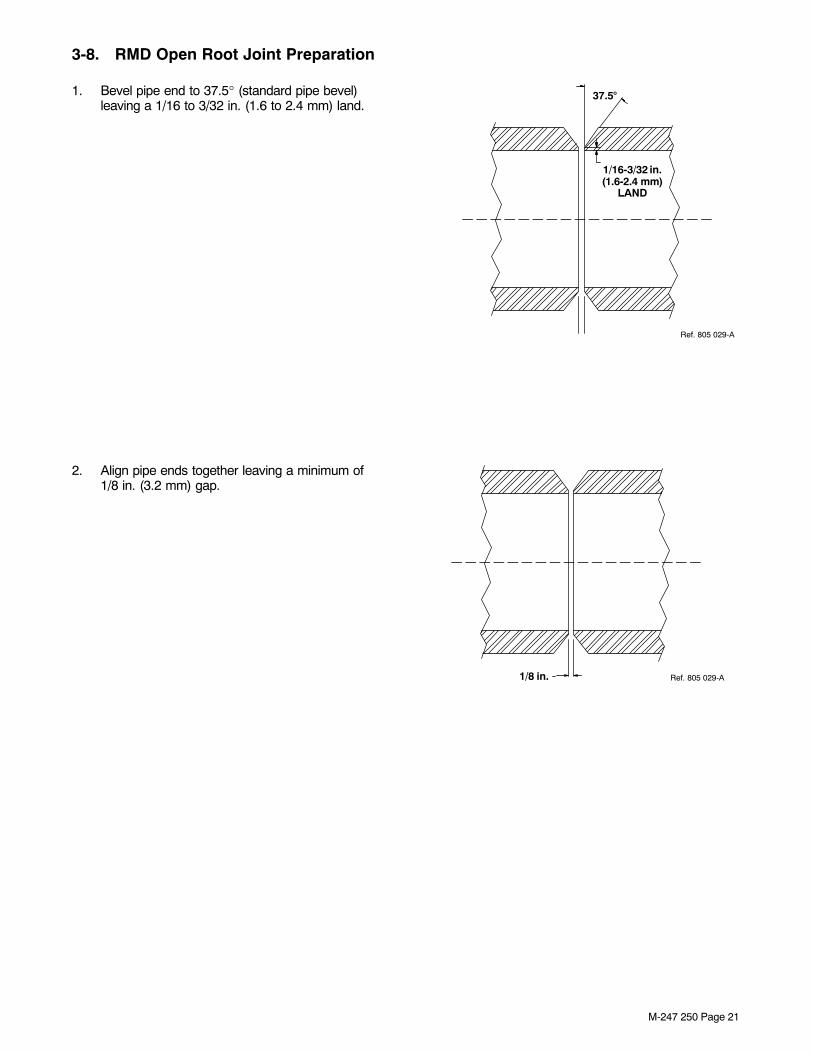
3-8. RMD Open Root Joint Preparation
1. Bevel pipe end to 37.5° (standard pipe bevel)leaving a 1/16 to 3/32 in. (1.6 to 2.4 mm) land.
37.5�
1/16-3/32 in.(1.6-2.4 mm)
LAND
Ref. 805 029-A
2. Align pipe ends together leaving a minimum of1/8 in. (3.2 mm) gap.
1/8 in. Ref. 805 029-A

M-247 250 Page 22
3. Tack pipe ends together in four locationsapproximately 90° apart and 1 in. (25.4 mm) long on pipe that is 6 in. (152.4 mm) or larger diameter. Use appropriate sized tack welds on smaller pipe. 90�
1 in. (25.4 mm)TACK WELDS
Ref. 805 029-A
4. Grind each end of the tack weld to a feather edge (knife edge).
Ref. 805 029-A
1 in.(25.4 mm)
GRIND TOFEATHER
EDGE

M-247 250 Page 23
3-9. 5G Welding Technique Recommendations
1. Start arc on sidewall or in center of tack weld, not in the gap.
805 024-A
MAINTAINDRAGANGLE
12 O’ CLOCK
6 O’ CLOCK
9 3
2. After puddle is established, maintain the arc on thecenter of the puddle with a 1/2 to 5/8 in. (12.7 to 15.9 mm) tip to work distance.
MAINTAINDRAGANGLE
10-15�
Ref. 805 025-A

M-247 250 Page 24
3. Move across the gap.
Ref. 805 025-A
4. Move slightly up the sidewall.
Ref. 805 025-A
5. Stay in the puddle and move the electrode back across the gap. Move the electrode down the joint in a half-moon motion.
Ref. 805 025-A

M-247 250 Page 25
6. Continue moving back and forth (weaving) across the gap until reaching the 1 o’clock position.
Ref. 805 025-A
7. At the 1 o’clock position, stop weaving.Concentrate the arc on the center of the weldpuddle and move down the pipe joint until the5 o’clock position.
805 026-A
8. At the 5 o’clock position, repeat steps 3 − 6.However, at Step 6 the instruction should read“until reaching the 6 o’clock position” instead of the1 o’clock position.
805 027-A
12 O’ CLOCK
9 3
6

M-247 250 Page 26
9. End the weld at the 6 o’clock position by moving the electrode onto the feathered tack weld.
805 028-A
12 O’ CLOCK
9 3
6
10. DO NOT stop welding in the root. This may cause pin holes.Be sure to grind the weld at the stop position to ensure pinhole is removed and weld is feathered.
Ref. 805 028-A
11 When root weld is complete, remove excesssilicon with a a wire wheel or with light grinding. Also, grind any high spots on root pass to make ituniform in height.

M-247 250 Page 27
3-10. 1G Welding Technique Recommendations
1. Start arc on sidewall or in center of tack weld, not in the gap.
805 024-A
MAINTAINDRAGANGLE
12 O’ CLOCK
6 O’ CLOCK
9 3
PIPEROTATING
2. After puddle is established, maintain the arc on theleading edge of the puddle with a 1/4 to 1/2 in.(6.4 to 12.7 mm) tip to work distance.
MAINTAINDRAGANGLE
10-15�
Ref. 805 025-A
PIPEROTATING

M-247 250 Page 28
3. Move across the gap. Watch the puddle, not the arc.
Ref. 805 025-A
PIPEROTATING
4. Move slightly up the sidewall. Keep the electrode near the top of the pipe joint.
Ref. 805 025-A
PIPEROTATING
5. Stay on the leading edge of the puddle and movethe electrode back across the gap. Move the electrode in a half-moon motion.
Ref. 805 025-A
PIPEROTATING

M-247 250 Page 29
6. Continue moving back and forth (weaving) across the gap. Be sure pipe rotates at a constant speed. Maintain a steady arc length.
Ref. 805 025-A
PIPEROTATING
10. DO NOT stop welding in the root. This may cause pin holes. Fill the crater by welding into theprevious weld start. Use a short arc length tocontrol heat.Be sure to grind the weld at the stop position to ensure any pinhole is removed and weld isfeathered.
Ref. 805 028-A
PIPEROTATING
11 When root weld is complete, remove excesssilicon with a a wire wheel or with light grinding. Also, grind any high spots on root pass to make ituniform in height.

M-247 250 Page 30
3-11. Welding Passes And Appropriate Process With Parameter RangesA. Welding Process Data
Table 3-6. PipePro 450 RFC Welding Programs
Steel
Process Wire Sizein (mm)
Wire Feed SpeedIPM (mpm)
Arc Adjust/Trim Arc Control Shielding Gas
RMD Steel
.035 (0.9) 100-300 w/200 Nominal(2.5-7.7 w/5.1 Nominal)
47-53 w/50 Nominal 25 90/10
.035 (0.9) 100-300 w/200 Nominal(2.5-7.7 w/5.1 Nominal)
47-53 w/50 Nominal 25 85/15
.035 (0.9) 100-300 w/200 Nominal(2.5-7.7 w/5.1 Nominal)
47-53 w/50 Nominal 25 75/25
.035 (0.9) 100-300 w/200 Nominal(2.5-7.7 w/5.1 Nominal)
47-53 w/50 Nominal 25 CO2
.040 (1.0) 100-275 w/175 Nominal(2.5-7.0 w/4.4 Nominal)
50-55 w/53 Nominal 25 90/10
.040 (1.0) 100-275 w/175 Nominal(2.5-7.0 w/4.4 Nominal)
47-53 w/50 Nominal 25 85/15
.040 (1.0) 100-275 w/175 Nominal(2.5-7.0 w/4.4 Nominal)
50-55 w/53 Nominal 25 75/25
.040 (1.0) 100-275 w/175 Nominal(2.5-7.0 w/4.4 Nominal)
50-55 w/53 Nominal 25 CO2
.045 (1.1) 100-200 w/150 Nominal(2.5-5.1 w/3.8 Nominal)
47-53 w/50 Nominal 25 90/10
.045 (1.1) 100-200 w/150 Nominal(2.5-5.1 w/3.8 Nominal)
47-53 w/50 Nominal 25 85/15
.045 (1.1) 100-200 w/150 Nominal(2.5-5.1 w/3.8 Nominal)
47-53 w/50 Nominal 25 75/25
.045 (1.1) 100-200 w/150 Nominal(2.5-5.1 w/3.8 Nominal)
47-53 w/50 Nominal 25 CO2
ProPulse Steel UsingA Positioner
(Rolling The Pipe)
.035 (0.9) 225-600 w/250 Nominal(5.7-15.2 w/6.4 Nominal)
52-57 w/56 Nominal 25 90/10
.035 (0.9) 120-780 w/250 Nominal3.0-19.8 w/6.4 Nominal
52-57 w/56 Nominal 30-35 85/15
.040 (1.0) 120-600 w/250 Nominal3.0-15.2 w/6.4 Nominal
52-56 w/56 Nominal 25 90/10
.040 (1.0) 120-600 w/250 Nominal3.0-15.2 w/6.4 Nominal
52-56 w/56 Nominal 25 85/15
.045 (1.1) 140-500 w/250 Nominal(3.6-12.7 w/6.4 Nominal)
52-57 w/56 Nominal 25 90/10
.045 (1.1) 140-500 w/250 Nominal(3.6-12.7 w/6.4 Nominal)
52-57 w/56 Nominal 25 85/15

M-247 250 Page 31
Table 3-6. PipePro 450 RFC Welding Programs (Continued)
Steel
Process Wire Sizein (mm)
Wire Feed SpeedIPM (mpm)
Arc Adjust/Trim Arc Control Shielding Gas
ProPulse SteelWelding In Position
.035 (0.9) 120-780 w/200 Nominal(3.0-19.8 w/5.1 Nominal)
52-57 w/54 Nominal 25 90/10
.035 (0.9) 120-780 w/200 Nominal(3.0-19.8 w/5.1 Nominal)
52-57 w/54 Nominal 30-35 85/15
.040 (1.0) 120-600 w/175 Nominal(3.0-15.2 w/4.4 Nominal)
52-56 w/54 Nominal 25 90/10
.040 (1.0) 120-600 w/175 Nominal(3.0-15.2 w/4.4 Nominal)
52-56 w/54 Nominal 25 85/15
.045 (1.1) 140-500 w/175 Nominal(3.6-12.7 w/4.4 Nominal)
50-55 w/53 Nominal 25 90/10
.045 (1.1) 140-500 w/175 Nominal(3.6-12.7 w/4.4 Nominal)
50-55 w/53 Nominal 25 85/15
Stainless Steel
Process Wire Sizein (mm)
Wire Feed SpeedIPM (mpm)
Arc Adjust/Trim Arc Control Shielding Gas
RMD Stainless Steel
.035 (0.9) 120-290 w/200 Nominal(3.0-7.4 w/5.1 Nominal)
47-51 w/50 Nominal 25 Tri-H
.040 (1.0) 120-275 w/200 Nominal(3.0-7.4 w/5.1 Nominal)
48-52 w/50 Nominal 30 Tri-H
.040 (1.0) 120-275 w/200 Nominal(3.0-7.4 w/5.1 Nominal)
48-52 w/50 Nominal 25 98/2 CO2
.040 (1.0) 120-275 w/200 Nominal(3.0-7.4 w/5.1 Nominal)
48-52 w/50 Nominal 25 98/2 Ox
.045 (1.1) 120-160 w/150 Nominal(3.0-4.1 w/3.8 Nominal)
48-52 w/50 Nominal 25 Tri-H

M-247 250 Page 32
Table 3-6. PipePro 450 RFC Welding Programs (Continued)
Stainless Steel
Process Wire Sizein (mm)
Wire Feed SpeedIPM (mpm)
Arc Adjust/Trim Arc Control Shielding Gas
ProPulseStainless Steel Using
A Positioner(Rolling The Pipe)
.035 (0.9) 150-780 w/175 Nominal(3.8-19.8 w/4.4 Nominal)
53-57 w/55 Nominal 25 Tri-H
.035 (0.9) 150-780 w/175 Nominal(3.8-19.8 w/4.4 Nominal)
52-57 w/56 Nominal 16 Tri-A
.035 (0.9) 150-780 w/175 Nominal(3.8-19.8 w/4.4 Nominal)
48-54 w/53 Nominal 18 98/2 CO2
.035 (0.9) 150-780 w/175 Nominal(3.8-19.8 w/4.4 Nominal)
48-52 w/51 Nominal 18 98/2 Ox
.045 (1.1) 140-450 w/200 Nominal(3.6-11.4 w/5.1 Nominal)
52-55 w/55 Nominal 25 Tri-H
.045 (1.1) 120-525 w/200 Nominal(3.0-13.3 w/5.1 Nominal)
53-57 w/55 Nominal 16 98/2 CO2
.045 (1.1) 120-525 w/200 Nominal(3.0-13.3 w/5.1 Nominal)
53-57 w/55 Nominal 25 98/2 Ox
ProPulseStainless Steel
Welding In Position
.035 (0.9) 150-780 w/175 Nominal(3.8-19.8 w/4.4 Nominal)
53-57 w/55 Nominal 25 Tri-H
.035 (0.9) 150-780 w/175 Nominal(3.8-19.8 w/4.4 Nominal)
52-56 w/54 Nominal 16 Tri-A
.035 (0.9) 150-780 w/175 Nominal(3.8-19.8 w/4.4 Nominal)
48-52 w/50 Nominal 18 98/2 CO2
.035 (0.9) 150-780 w/175 Nominal(3.8-19.8 w/4.4 Nominal)
46-50 w/48 Nominal 18 98/2 Ox
.045 (1.1) 120-525 w/140 Nominal(3.0-13.3 w/3.6 Nominal)
53-57 w/55 Nominal 25 Tri-H
.045 (1.1) 120-525 w/140 Nominal(3.0-13.3 w/3.6 Nominal)
50-55 w/53 Nominal 16 98/2 CO2
.045 (1.1) 120-525 w/140 Nominal(3.0-13.3 w/3.6 Nominal)
50-55 w/53 Nominal 25 98/2 Ox
.045Inconel 625
150-500 w/300 Nominal(3.8-12.7 w/7.6 Nominal)
50-55 w/53 Nominal 25-30 Argon

M-247 250 Page 33
Table 3-6. PipePro 450 RFC Welding Programs (Continued)
Flux Core
ProcessWire Sizein (mm)
Rolling Pipe/In Position Wire Feed Speed
IPM (mpm)
Voltage — — Shielding Gas
Flux Core/GMAW .045 (1.1) 175-780 w/200 Nominal(4.4-19.8 w/5.1 Nominal)*
24.5-32 w/24.5Nominal
— — 75/25*
Note: Arc Control is arc width and Arc Adjust/Trim is arc length. Wire feed speed and voltage are synergic for theRMD and ProPulse processes. Therefore, when adjusting wire feed speed, the voltage is automatically adjusted so itis not necessary to adjust Arc Adjust/Trim. These are only starting parameters, the operator must make finaladjustments depending on material and conditions.
*See wire manufacturer for recommended wire feed speed and gas mixture.

M-247 250 Page 34
Table 3-7. PipeWorx 400 Welding Parameters
Steel
Process Wire Sizein. (mm)
Wire Feed SpeedIPM (mpm)
Arc Length Shielding Gas
RMD Steel
.035 (0.9) 100-350 w/200 Nominal(2.5-8.9 w/5.1 Nominal)
+3.0 to −3.0w/zero Nominal
C8 − C15
.035 (0.9) 100-350 w/200 Nominal(2.5-8.9 w/5.1 Nominal)
+3.0 to −3.0w/zero Nominal
C20 − C25
.035 (0.9) 100-250 w/200 Nominal(2.5-6.4 w/5.1 Nominal)
+3.0 to −3.0w/zero Nominal
CO2
.045 (1.1) 100-250 w/150 Nominal(2.5-6.4 w/3.8 Nominal)
+3.0 to −3.0w/zero Nominal
C8 − C15
.045 (1.1) 100-250 w/150 Nominal(2.5-6.4 w/3.8 Nominal)
+3.0 to −3.0w/zero Nominal
C20 − C25
.045 (1.1) 100-200 w/150 Nominal(2.5-5.1 w/3.8 Nominal)
+3.0 to −3.0w/zero Nominal
CO2
ProPulse Steel Using APositioner
1G(Rolling The Pipe)
.035 (0.9) 120-780 w/250 Nominal(3.0-19.8 w/6.4 Nominal)
+3.0 to −3.0w/zero Nominal
C8 − C15
.045 (1.1) 140-500 w/250 Nominal(3.6-12.7 w/6.4 Nominal)
+3.0 to −3.0w/zero Nominal
C8 − C15
ProPulse SteelWelding In Position
5G
.035 (0.9) 120-780 w/200 Nominal(3.0-19.8 w/5.1 Nominal)
+3.0 to −3.0w/zero Nominal
C8 − C15
.045 (1.1) 140-500 w/175 Nominal(3.6-12.7 w/4.4 Nominal)
+3.0 to −3.0w/zero Nominal
C8 − C15

M-247 250 Page 35
Table 3-7. PipeWorx 400 Welding Parameters (Continued)
Stainless Steel
Process Wire Sizein. (mm)
Wire Feed SpeedIPM (mpm)
Arc Length Shielding Gas
RMD Stainless Steel
.035 (0.9) 120-350 w/200 Nominal(3.0-8.9 w/5.1 Nominal)
+3.0 to −3.0w/zero Nominal
C2
.035 (0.9) 120-350 w/200 Nominal(3.0-8.9 w/5.1 Nominal)
+3.0 to −3.0w/zero Nominal
98/2 Ox
.035 (0.9) 120-350 w/200 Nominal(3.0-8.9 w/5.1 Nominal)
+3.0 to −3.0w/zero Nominal
Tri-H
.035 (0.9) 120-350 w/200 Nominal(3.0-8.9 w/5.1 Nominal)
+3.0 to −3.0w/zero Nominal
Tri-A
.045 (1.1) 120-250 w/150 Nominal(3.0-6.4 w/3.8 Nominal)
+3.0 to −3.0w/zero Nominal
C2
.045 (1.1) 120-250 w/150 Nominal(3.0-6.4 w/3.8 Nominal)
+3.0 to −3.0w/zero Nominal
98/2 Ox
.045 (1.1) 120-250 w/150 Nominal(3.0-6.4 w/3.8 Nominal)
+3.0 to −3.0w/zero Nominal
Tri-H
.045 (1.1) 120-250 w/150 Nominal(3.0-6.4 w/3.8 Nominal)
+3.0 to −3.0w/zero Nominal
Tri-A

M-247 250 Page 36
Table 3-7. PipeWorx 400 Welding Parameters (Continued)
Stainless Steel
Process Wire Sizein. (mm)
Wire Feed SpeedIPM (mpm)
Arc Length Shielding Gas
ProPulseStainless Steel Using A
Positioner1G
(Rolling The Pipe)
.035 (0.9) 150-780 w/250 Nominal(3.8-19.8 w/6.4 Nominal)
+3.0 to −3.0w/zero Nominal
C2
.035 (0.9) 150-780 w/250 Nominal(3.8-19.8 w/6.4 Nominal)
+3.0 to −3.0w/zero Nominal
98/2 Ox
.035 (0.9) 225-600 w/250 Nominal(5.7-15.2 w/6.4 Nominal)
+3.0 to −3.0w/zero Nominal
Tri-H
.035 (0.9) 150-780 w/250 Nominal(3.8-19.8 w/6.4 Nominal)
+3.0 to −3.0w/zero Nominal
Tri-A
.045 (1.1) 120-780 w/200 Nominal(3.0-19.8 w/5.1 Nominal)
+3.0 to −3.0w/zero Nominal
C2
.045 (1.1) 120-780 w/200 Nominal(3.0-19.8 w/5.1 Nominal)
+3.0 to −3.0w/zero Nominal
98/2 Ox
.045 (1.1) 140-780 w/200 Nominal(3.6-19.8 w/5.1 Nominal)
+3.0 to −3.0w/zero Nominal
Tri-H
.045 (1.1) 120-780 w/200 Nominal(3.0-19.8 w/5.1 Nominal)
+3.0 to −3.0w/zero Nominal
Tri-A
ProPulseStainless Steel
Welding In Position5G
.035 (0.9) 150-780 w/175 Nominal(3.8-19.8 w/4.4 Nominal)
+3.0 to −3.0w/zero Nominal
C2
.035 (0.9) 150-780 w/175 Nominal(3.8-19.8 w/4.4 Nominal)
+3.0 to −3.0w/zero Nominal
98/2 Ox
.035 (0.9) 150-780 w/175 Nominal(3.8-19.8 w/4.4 Nominal)
+3.0 to −3.0w/zero Nominal
Tri-H
.035 (0.9) 150-780 w/175 Nominal(3.8-19.8 w/4.4 Nominal)
+3.0 to −3.0w/zero Nominal
Tri-A
.045 (1.1) 120-525 w/140 Nominal(3.0-13.3 w/3.6 Nominal)
+3.0 to −3.0w/zero Nominal
C2
.045 (1.1) 120-525 w/140 Nominal(3.0-13.3 w/3.6 Nominal)
+3.0 to −3.0w/zero Nominal
98/2 Ox
.045 (1.1) 120-525 w/140 Nominal(3.0-13.3 w/3.6 Nominal)
+3.0 to −3.0w/zero Nominal
Tri-H
.045 (1.1) 120-525 w/140 Nominal(3.0-13.3 w/3.6 Nominal)
+3.0 to −3.0w/zero Nominal
Tri-A

M-247 250 Page 37
Table 3-7. PipeWorx 400 Welding Parameters (Continued)
Flux Core
ProcessWire Sizein. (mm)
Rolling Pipe/In Position Wire Feed Speed
IPM (mpm)
Voltage Shielding Gas
Flux Core/GMAW NotDependent
175-780 w/200 Nominal(4.4-19.8 w/5.1 Nominal)*
24.5-32 w/24.5 Nominal Not Dependent
Note: Arc Length − Length of arc from end of wire to weld puddle. Wire feed speed and voltage are synergic for theRMD and ProPulse processes. This means when adjusting wire feed speed, the voltage is automatically adjusted soit is not necessary to adjust the Arc Length.
*See wire manufacturer for recommended wire feed speed and gas mixture.
B. Root Pass
The first weld pass is referred to as the root pass and is used to fill the gap between two sections of pipe. Whenusing the GMAW process, the root pass is usually with an open root weld (no backing ring). Generally, a manualweld root pass is continuous all the way around and through the tack welds.
C. Hot Pass
The hot pass is usually a single weld that joins the root weld and both groove faces together. A split hot pass isgenerally an acceptable procedure for 2G welding and when the root opening is larger than normal.
D. Fill Pass
The fill pass should nearly fill the groove. If a bead sequence is necessary, an alternating pattern should be usedfrom face to face of the joint. The location of each bead should have an adequate, uniform lap for eachsubsequent weld bead. If a narrow cavity should develop between weld beads or between the face of the jointand the weld bead it may result in a lack of fusion or contamination (slag). If possible, grind the area to eliminatethe cavity and improve the lap weld before making the next weld.
E. Cap Pass
The cap weld should completely fill the top of the joint with the least amount of excessive build-up beyond the topsurface of the pipe. Grinding may be necessary to improve the weld bead shape and remove any contaminationbefore making the final cap pass.

M-247 250 Page 38
3-12. Troubleshooting Guide
A. Process Issues
Trouble Possible Causes Remedy
Undercutting Travel speed too high Slow down travel speed
Welding voltage too high Decrease arc length, trim or voltage
Dwell time not long enough Pause longer while weaving
Gun angle Maintain 10 to 15 degree drag angle in RMD and 5 to10 degree angle in pulse
Porosity Inadequate shielding gas coverage Check flowmeter for 35 to 50 SCFH
Gas in contaminated/leaky connections Check fittings, hoses and shielding gas connections
Electrode contamination Replace electrode
Workpiece contamination Remove paint, mill scale, rust, oil, and oxide
Arc Voltage too high Decrease arc length, trim or voltage
Excessive contact tube to work distance 3/8 to 5/8 in. (10 to 16 mm) stick-out for RMD or pulse3/4 to 1 in (19 to 25 mm) stick-out for FCAW
Incomplete fusion Weld zone surfaces not free of film or excessive oxide Grind or sand to clean off surface
Insufficient heat input Increase wire feed speed
Too large of a weld puddle Increase travel speed or decrease wire feed speed
Improper welding technique Re-evaluate welding method for proper technique
Improper joint preparation Increase joint angle
Excessive travel speed Decrease travel speed or increase wire feed speed
Humping and crowning Excessive travel speed Slow down travel speed or weave electrode
unmelted electrode on rootside (“whiskers”)
Improper welding technique Focus electrode back further on weld puddle
Spatter Long arc length Shorten arc length or decrease voltage
Bad shielding gas Replace shielding gas
Welding in globular transfer range (Argon gas) Decrease voltage
Excessive melt through Excessive heat input Reduce wire feed speed
Improper joint penetration Shorten root opening
Other issues Unable to resolve problem Contact factory pipe welding products service(920−735−4001)
B. Parameter Issues
Change Required Arc Voltage Welding Current Travel Speed
Deeper penetration Increase
Shallower penetration Decrease
Larger bead Increase Decrease
Smaller bead Decrease Increase
Higher, narrower bead Decrease
Flatter, wider bead Increase
Faster deposition Increase
Slower deposition Decrease

− 39 −
Notes
FILLETGROOVE
WELD JOINTTYPES
BUTT
BUTT
BUTT
BUTT
T−JOINT
T−JOINT
T−JOINT
T−JOINT
FLAT
VERTICAL
HORIZONTAL
OVERHEAD
WELD POSITION:
Ref. AWS/ANSI D1.1
1G
1F
2G
2F
3G
3F
4G
4F
Ref. 804 248-A

ORIGINAL INSTRUCTIONS − PRINTED IN USA © 2010 Miller Electric Mfg. Co. 2010−01
Miller Electric Mfg. Co.An Illinois Tool Works Company1635 West Spencer StreetAppleton, WI 54914 USA
International Headquarters−USAUSA Phone: 920-735-4505 Auto-AttendedUSA & Canada FAX: 920-735-4134International FAX: 920-735-4125
For International Locations Visitwww.MillerWelds.com