midwest regional carbon sequestration partnershipsecarbon.org/wp-content/uploads/2014/03/11 -...
TRANSCRIPT
Midwest Regional Carbon Sequestration Partnership DOE/NETL Cooperative Agreement # DE-FC26-0NT42589
Lydia Cumming, Battelle
9th Annual SECARB Stakeholders’ Briefing March 5, 2014
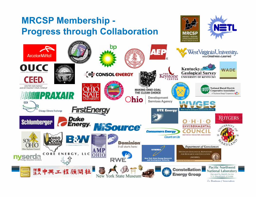
MRCSP Membership - Progress through Collaboration
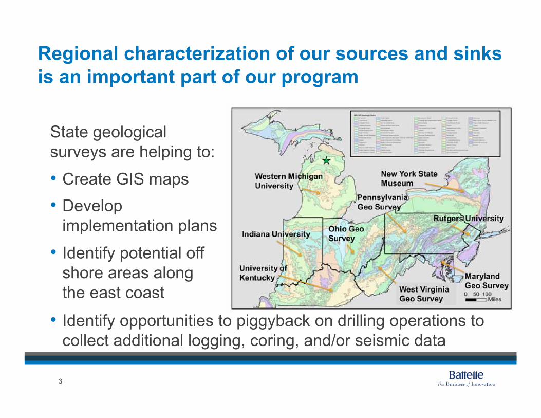
Regional characterization of our sources and sinks is an important part of our program
State geological surveys are helping to:
•!Create GIS maps •!Develop
implementation plans
•! Identify potential off shore areas along the east coast
•! Identify opportunities to piggyback on drilling operations to collect additional logging, coring, and/or seismic data
3
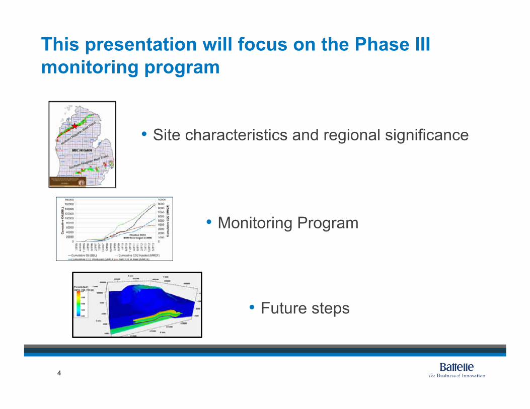
This presentation will focus on the Phase III monitoring program
4
•!Site characteristics and regional significance
•!Monitoring Program
•! Future steps
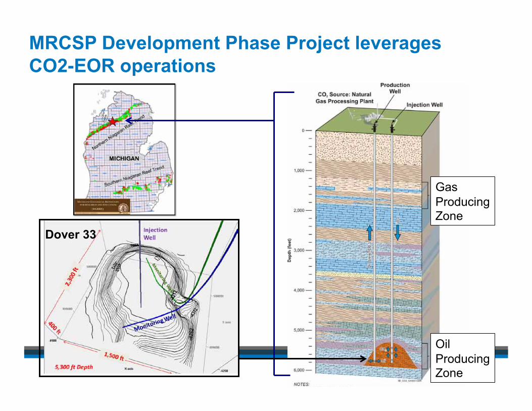
MRCSP Development Phase Project leverages CO2-EOR operations
Gas Producing Zone
Oil Producing Zone
Dover 33
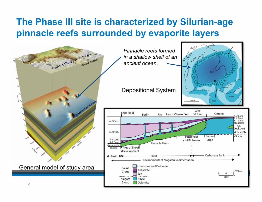
Pinnacle reefs formed in a shallow shelf of an ancient ocean.
The Phase III site is characterized by Silurian-age pinnacle reefs surrounded by evaporite layers
6
General model of study area
Depositional System
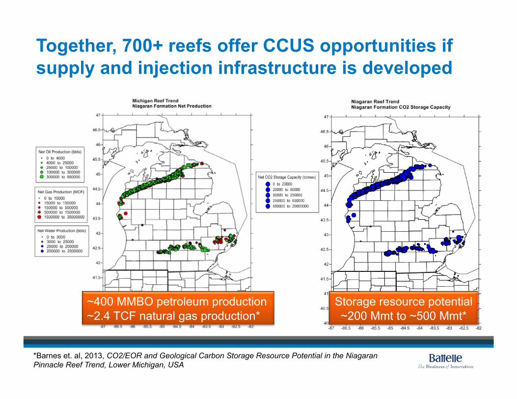
Together, 700+ reefs offer CCUS opportunities if supply and injection infrastructure is developed
~400 MMBO petroleum production ~2.4 TCF natural gas production*
Storage resource potential ~200 Mmt to ~500 Mmt*
*Barnes et. al, 2013, CO2/EOR and Geological Carbon Storage Resource Potential in the Niagaran Pinnacle Reef Trend, Lower Michigan, USA
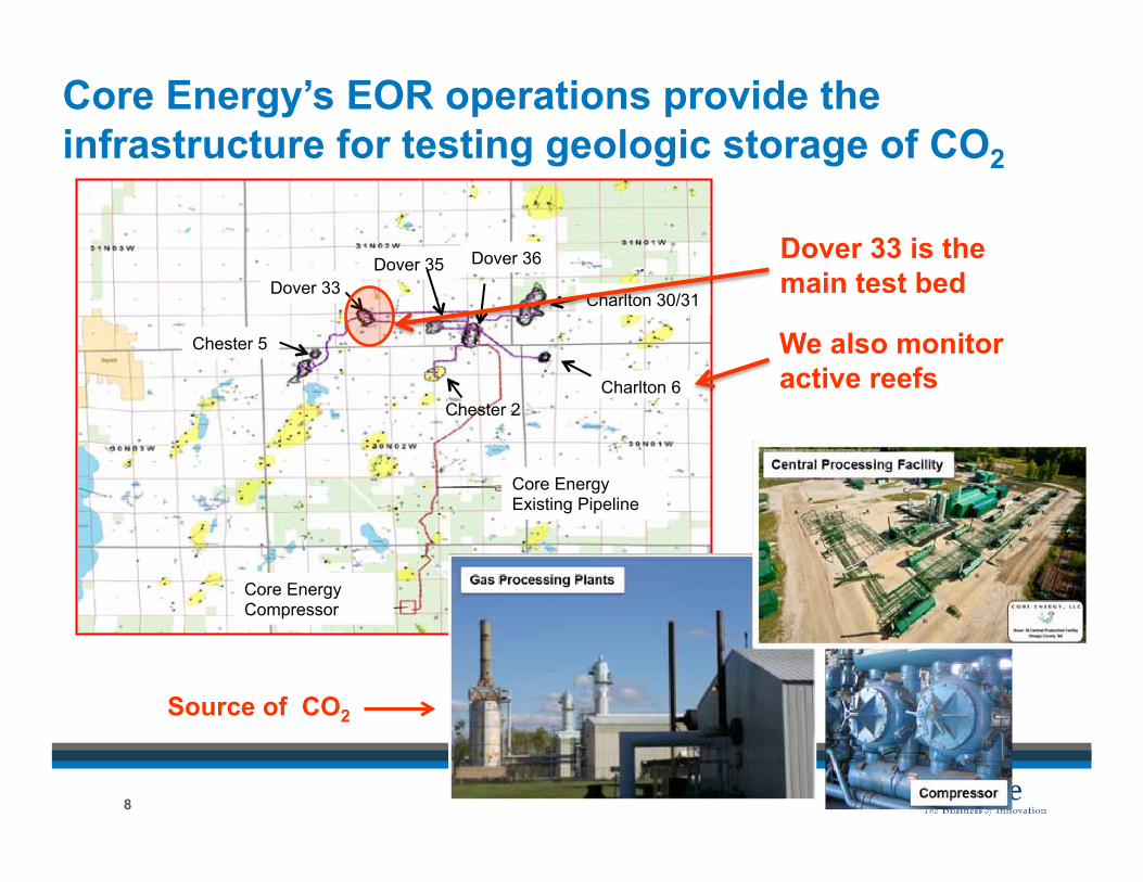
Core Energy’s EOR operations provide the infrastructure for testing geologic storage of CO2
Core Energy Compressor
Core Energy Existing Pipeline
Charlton 6
Charlton 30/31 Dover 33
Dover 35
Chester 5
Dover 36
Chester 2
Dover 33 is the main test bed
We also monitor active reefs
Source of CO2
8
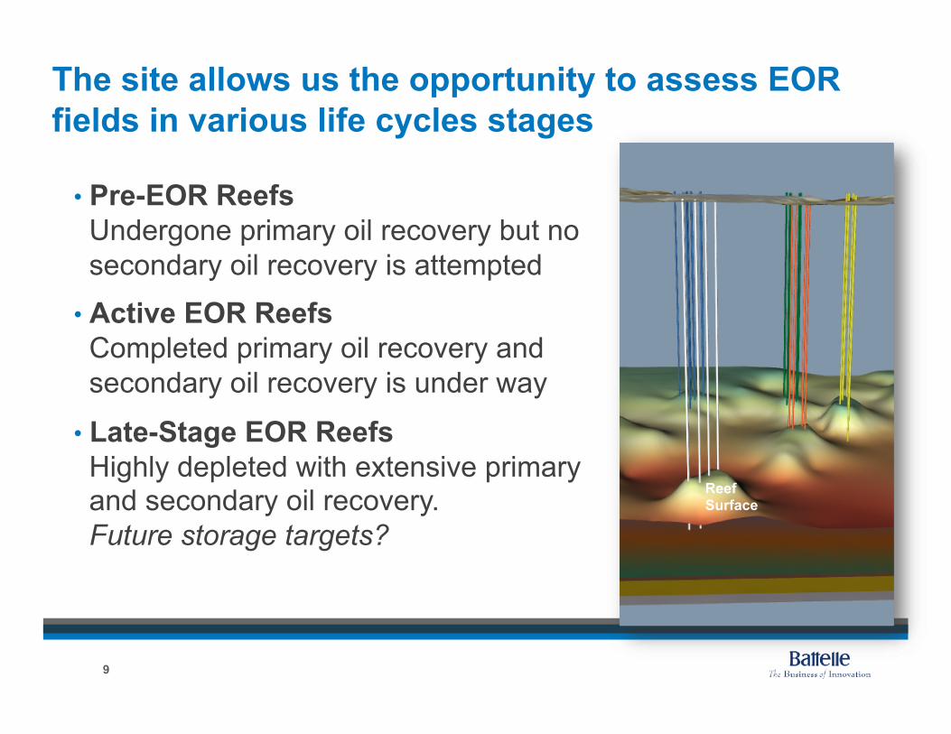
The site allows us the opportunity to assess EOR fields in various life cycles stages
Reef Surface
•!Pre-EOR Reefs Undergone primary oil recovery but no secondary oil recovery is attempted
•!Active EOR Reefs Completed primary oil recovery and secondary oil recovery is under way
•!Late-Stage EOR Reefs Highly depleted with extensive primary and secondary oil recovery. Future storage targets?
9
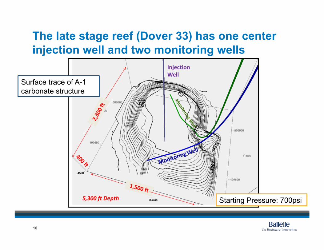
The late stage reef (Dover 33) has one center injection well and two monitoring wells
10
Surface trace of A-1 carbonate structure
Starting Pressure: 700psi
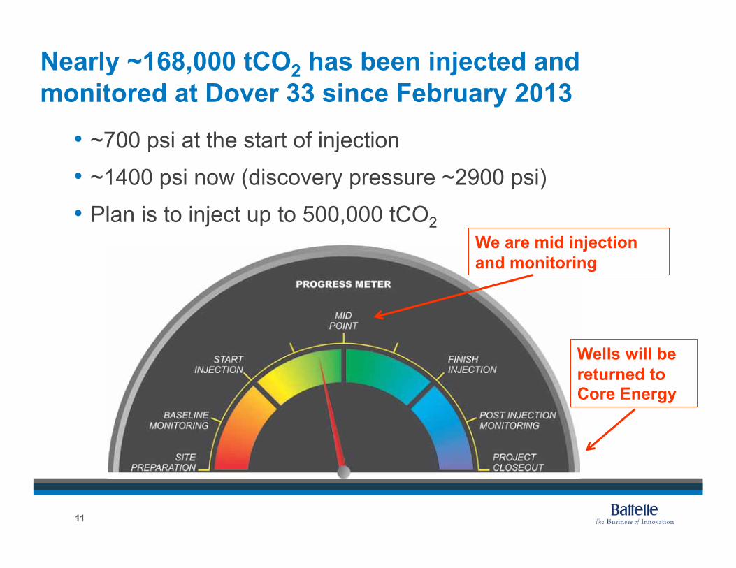
Nearly ~168,000 tCO2 has been injected and monitored at Dover 33 since February 2013
•! ~700 psi at the start of injection
•! ~1400 psi now (discovery pressure ~2900 psi)
•!Plan is to inject up to 500,000 tCO2
11
Wells will be returned to Core Energy
We are mid injection and monitoring
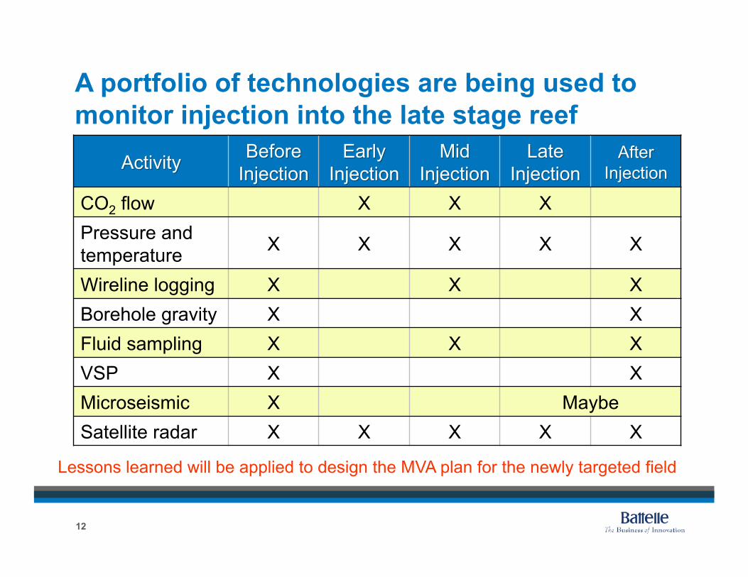
A portfolio of technologies are being used to monitor injection into the late stage reef
12
Lessons learned will be applied to design the MVA plan for the newly targeted field
CO2 flow X X X Pressure and temperature X X X X X
Wireline logging X X X Borehole gravity X X Fluid sampling X X X VSP X X Microseismic X Maybe Satellite radar X X X X X

CO2 flowrates, pressure and temperature at Dover 33 are being monitored continuously
•!Routine performance monitoring
•!Pressure fall off tests for reservoir analysis
•!Understanding hydraulic properties and CO2 phase behavior
13
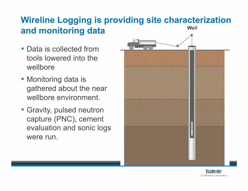
Wireline Logging is providing site characterization and monitoring data
•!Data is collected from tools lowered into the wellbore •!Monitoring data is
gathered about the near wellbore environment.
•!Gravity, pulsed neutron capture (PNC), cement evaluation and sonic logs were run.
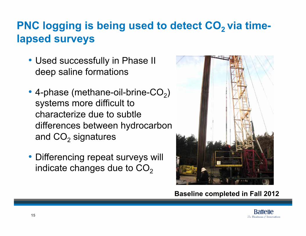
•!Used successfully in Phase II deep saline formations
•! 4-phase (methane-oil-brine-CO2) systems more difficult to characterize due to subtle differences between hydrocarbon and CO2 signatures
•!Differencing repeat surveys will indicate changes due to CO2
PNC logging is being used to detect CO2 via time-lapsed surveys
15
Baseline completed in Fall 2012
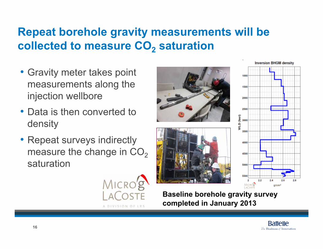
•!Gravity meter takes point measurements along the injection wellbore •!Data is then converted to
density
•!Repeat surveys indirectly measure the change in CO2 saturation
Repeat borehole gravity measurements will be collected to measure CO2 saturation
Baseline borehole gravity survey completed in January 2013
16
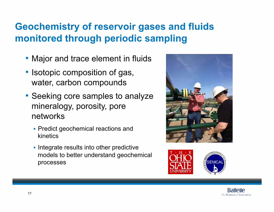
•!Major and trace element in fluids
•! Isotopic composition of gas, water, carbon compounds •!Seeking core samples to analyze
mineralogy, porosity, pore networks !! Predict geochemical reactions and
kinetics
!! Integrate results into other predictive models to better understand geochemical processes
Geochemistry of reservoir gases and fluids monitored through periodic sampling
17
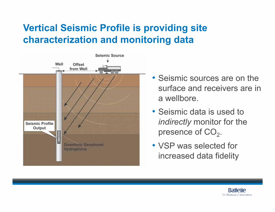
Vertical Seismic Profile is providing site characterization and monitoring data
•!Seismic sources are on the surface and receivers are in a wellbore. •!Seismic data is used to
indirectly monitor for the presence of CO2.
•!VSP was selected for increased data fidelity
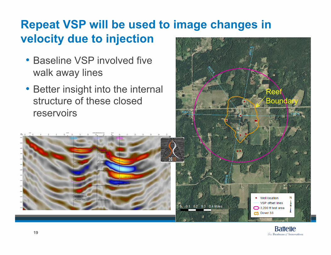
•!Baseline VSP involved five walk away lines
•!Better insight into the internal structure of these closed reservoirs
Repeat VSP will be used to image changes in velocity due to injection
19
Reef Boundary
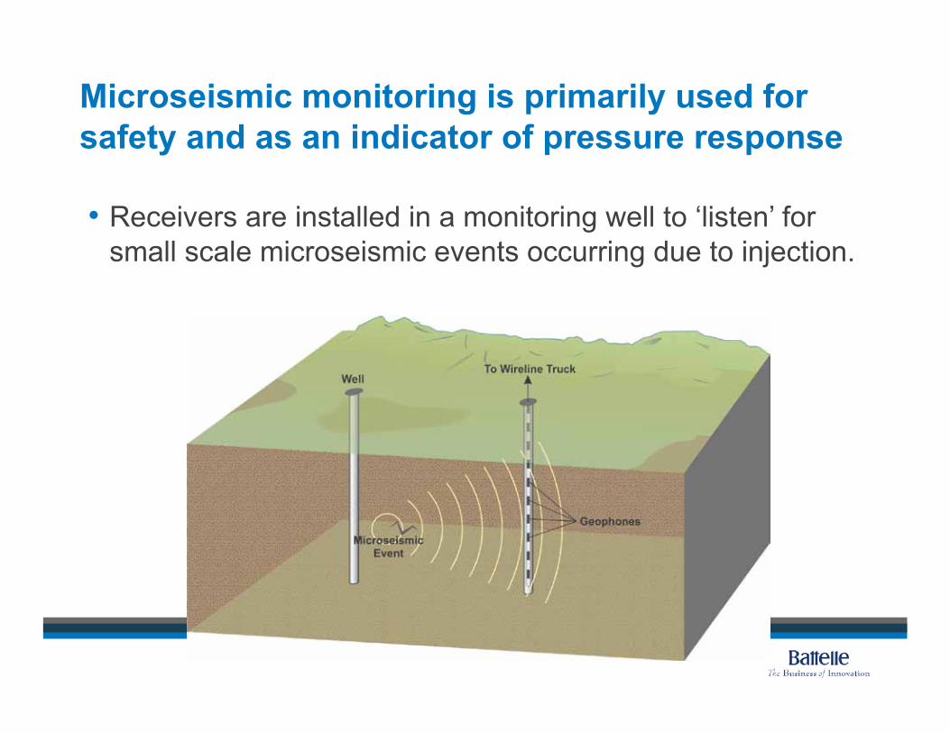
Microseismic monitoring is primarily used for safety and as an indicator of pressure response
•!Receivers are installed in a monitoring well to ‘listen’ for small scale microseismic events occurring due to injection.
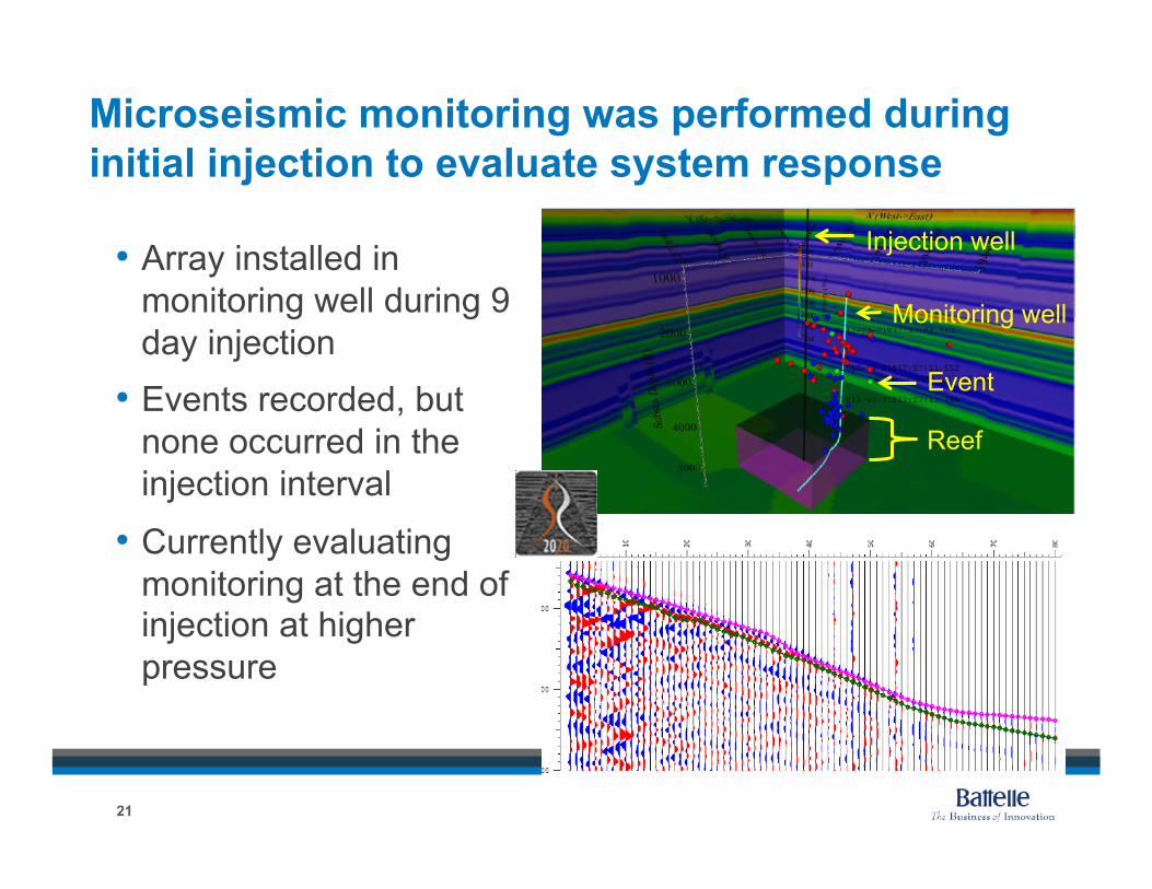
Microseismic monitoring was performed during initial injection to evaluate system response
•!Array installed in monitoring well during 9 day injection •!Events recorded, but
none occurred in the injection interval
•!Currently evaluating monitoring at the end of injection at higher pressure
21
Reef
Monitoring well
Injection well
Event
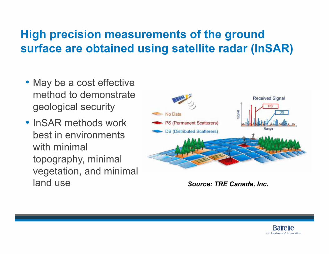
High precision measurements of the ground surface are obtained using satellite radar (InSAR)
•!May be a cost effective method to demonstrate geological security •! InSAR methods work
best in environments with minimal topography, minimal vegetation, and minimal land use Source: TRE Canada, Inc.
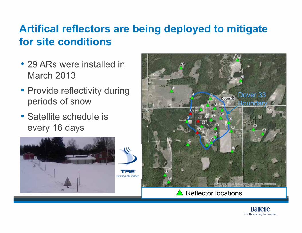
Artifical reflectors are being deployed to mitigate for site conditions
•! 29 ARs were installed in March 2013
•!Provide reflectivity during periods of snow
•!Satellite schedule is every 16 days
Reflector locations
Dover 33 Boundary
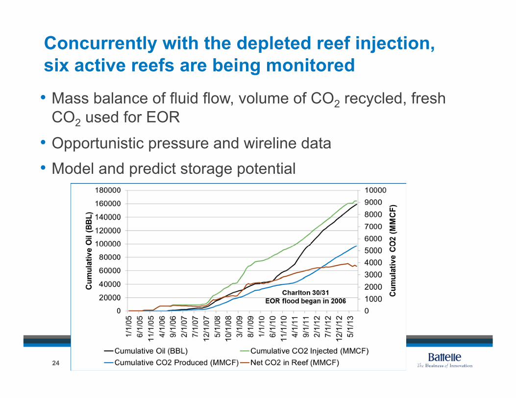
Concurrently with the depleted reef injection, six active reefs are being monitored
•!Mass balance of fluid flow, volume of CO2 recycled, fresh CO2 used for EOR
•!Opportunistic pressure and wireline data •!Model and predict storage potential
24
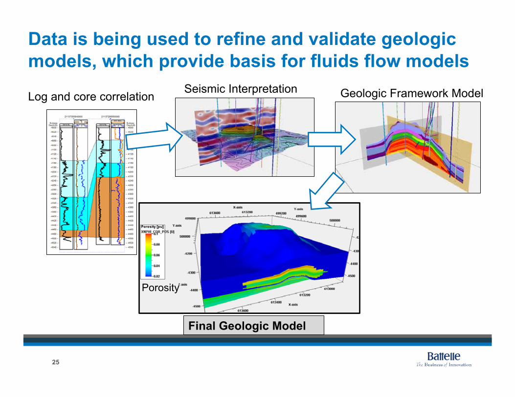
Data is being used to refine and validate geologic models, which provide basis for fluids flow models
Log and core correlation Seismic Interpretation Geologic Framework Model
Final Geologic Model
Porosity
25
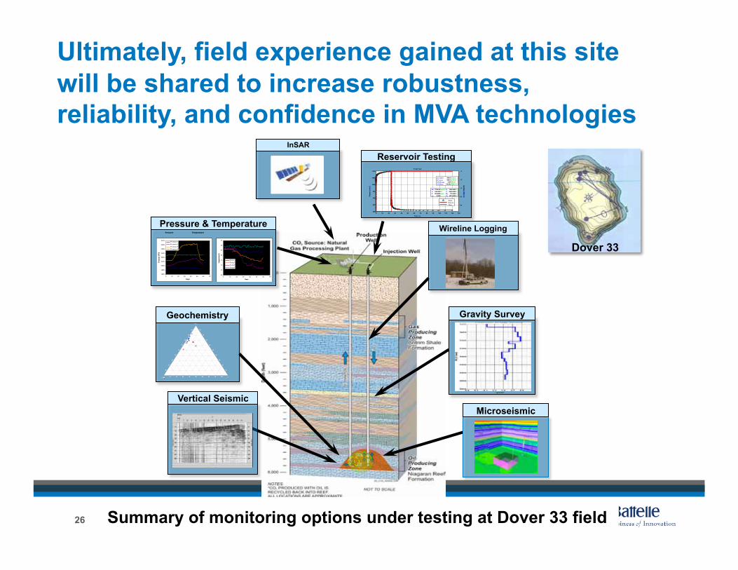
Ultimately, field experience gained at this site will be shared to increase robustness, reliability, and confidence in MVA technologies
Dover 33
Summary of monitoring options under testing at Dover 33 field
Vertical Seismic
Geochemistry
Wireline Logging
Microseismic
Reservoir Testing InSAR
Gravity Survey
Pressure & Temperature Pressure Temperature
26