microwaves in gyromagnetic waveguides
TRANSCRIPT

Microwaves in gyromagnetic waveguidesZhong Wu, Qi Wang, Chun-Fang Li, and Jie-Long Shi Citation: Journal of Applied Physics 89, 535 (2001); doi: 10.1063/1.1323748 View online: http://dx.doi.org/10.1063/1.1323748 View Table of Contents: http://scitation.aip.org/content/aip/journal/jap/89/1?ver=pdfcov Published by the AIP Publishing Articles you may be interested in Dipole-exchange theory of hybrid electromagnetic-spin waves in layered film structures J. Appl. Phys. 91, 10007 (2002); 10.1063/1.1475373 Dispersion of the pinning field direction of a ferromagnet/antiferromagnet coupled system Appl. Phys. Lett. 78, 237 (2001); 10.1063/1.1335842 Antiferromagnetically coupled magnetic media layers for thermally stable high-density recording Appl. Phys. Lett. 77, 3806 (2000); 10.1063/1.1329868 Magnetization reversal of ferromagnetic/antiferromagnetic bilayers Appl. Phys. Lett. 77, 423 (2000); 10.1063/1.126997 Nonlinear characteristics of magnetooptic Bragg diffraction in bismuth substituted yttrium iron garnet films J. Appl. Phys. 87, 1474 (2000); 10.1063/1.372037
[This article is copyrighted as indicated in the article. Reuse of AIP content is subject to the terms at: http://scitation.aip.org/termsconditions. Downloaded to ] IP:
140.254.87.149 On: Sat, 20 Dec 2014 03:53:36

Microwaves in gyromagnetic waveguidesZhong Wu,a) Qi Wang, Chun-Fang Li, and Jie-Long ShiDepartment of Physics, Shanghai University, Baoshan, Shanghai 200436, China
~Received 6 March 2000; accepted for publication 15 September 2000!
Properties of transverse electric waves in the microwave frequency range on a plane interfacebetween a nonlinear antiferromagnet and a linear ferromagnet are investigated. It is revealed thatthere are two different field distributions and powers. An exact analytical dispersion relation isobtained. On the basis of the dispersion relation, we have investigated the properties of surfacewaves in this waveguide and, theoretically, found that there exist passbands and stop bands, whichcan be controlled by varying the power in the nonlinear gyromagnetic waveguides. ©2001American Institute of Physics.@DOI: 10.1063/1.1323748#
I. INTRODUCTION
In the last decade or so, the availability of high-qualitygyromagnetic crystals has led to a growing interest in non-linear magnetic waves. The interactions of gyromagneticcrystals with infrared waves or microwaves have drawnmuch attention.1–14 And, many distinguishing features havebeen discovered in gyromagnetic waveguides. Microwave-magnetic-envelope solitons have been observed in yttrium–iron–garnet~YIG! films within the usable low-transmission-loss portion of the magnetostatic forward-volume-waveband.8 Increasing input power produces multiple-peak pro-files characteristics of backward microwave-magnetic-envelope solitons.9 The self-channeling and nonlinear beamshaping of magnetostatic waves in thin in-plane magnetizedYIG films have been observed as the input power reached athreshold value equal to a few hundred milliwatts because ofthe interplay between the diffraction of the beam andnonlinearity.15 Nonlinear transverse-magnetic~TM! surfacewaves in antiferromagnets do not exist within some certainfrequency regions.4,6
Recently, we have studied the frequency characteristicsof magnetic spatial solitons on the surface of two-sublatticeuniaxial antiferromagnetic crystal.4,6 The distinguishing fea-ture of the soliton is the existence of the frequency pass-band~s! and stop band~s! that can be switched into each otherby varying the power. In gyromagnetic waveguides the the-oretical analysis of transverse-electric~TE! waves is morecomplicated than that of TM waves. On the contrary, in di-electric waveguides the theoretical analysis of TM waves ismore complicated than that of TE waves. The reason is thatthe two electric-field components of TM waves cannot beseparated in the boundary-value problem. In 1987, a limitmethod was used to obtain a rigorous dispersion relation forTM surface waves on a dielectric material.16 With the help ofthe limit method idea we have investigated the nonlinearpropagation of TE waves with microwave frequencies on theinterface between a nonlinear antiferromagnet and a lineardielectric.17
In this article, we have studied the TE surface waves ona plane interface between a linear ferromagnet and a two-sublattice uniaxial nonlinear antiferromagnet. The study ofTE waves on the interface between an antiferromagnet and aferromagnet is much more complicated than what we inves-tigated before because both the permeabilities for antiferro-magnet and ferromagnet are tensors and the two componentsof magnetic fields cannot be easily separated in theboundary-value problem.
The resonance frequency for antiferromagnets lies in theinfrared and that for ferromagnets is in the microwave re-gime. Antiferromagnets of the type (FeF2, MnF2) under dis-cussion are characterized by an effective exchange field~;500 kOe! which greatly exceeds the effective anisotropyfield ~;10 kOe! and the intensities of the magnetic fields~;10 Oe! of incident waves. For ferromagnets, a static biasmagnetic field is needed to align the spins.
This article is organized as follows. In Sec. II the fielddistributions under the conditions of small power and largepower are presented. In Sec. III the dispersion relation in theregion of microwave frequencies is introduced, and thepower calculated. Section IV contains the properties of TEsurface waves, and in Sec. V the effects of power and rel-evant parameters on the bandwidths are investigated.
II. FIELD DISTRIBUTIONS
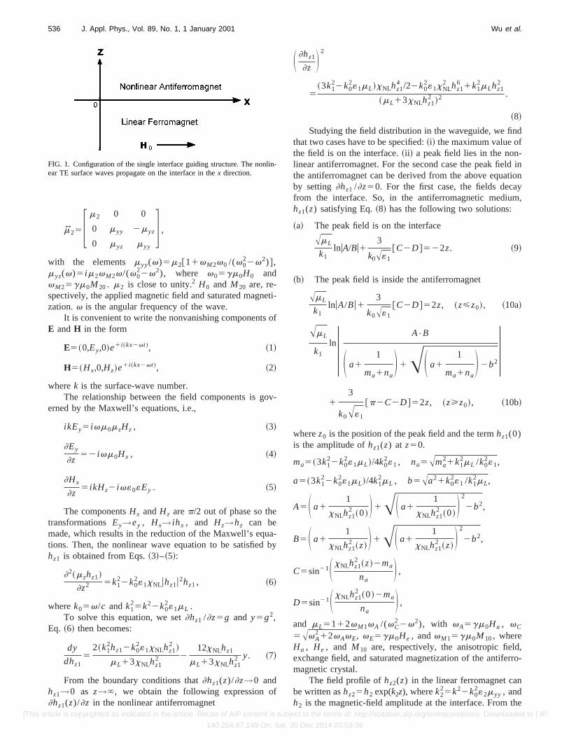
The structure of the waveguide consists of a nonlinearantiferromagnet («1 ,mJ 1), occupying the half spacez.0, anda linear ferromagnet («2 ,mJ 2), occupying the half spacez,0, as shown in Fig. 1. The nonlinear cladding is labeledwith ‘‘1’’ and the linear substrate is labeled with ‘‘2.’’ Theeasy-magnetization axes of both materials are in the1x or2x direction. A static bias magnetic fieldH0 is applied tothe ferromagnet along thex axis. We consider TE waves thatpropagate in thex direction. The permeabilitymJ 1 that de-scribes the antiferromagnet crystal is a third-rank diagonaltensor, i.e., mx51, my5mL(v), mz5mL(v)1xNLuHzu2,wheremL(v) is the linear part of the permeability andxNL isthe relative nonlinear permeability coefficient without exter-nal dc magnetic field. And for the ferromagnet2a!Electronic mail: [email protected]
JOURNAL OF APPLIED PHYSICS VOLUME 89, NUMBER 1 1 JANUARY 2001
5350021-8979/2001/89(1)/535/7/$18.00 © 2001 American Institute of Physics
[This article is copyrighted as indicated in the article. Reuse of AIP content is subject to the terms at: http://scitation.aip.org/termsconditions. Downloaded to ] IP:
140.254.87.149 On: Sat, 20 Dec 2014 03:53:36
mJ 25F m2 0 0
0 myy 2myz
0 myz myy
G ,
with the elements myy(v)5m2@11vM2v0 /(v022v2)#,
myz(v)5 im2vM2v/(v022v2), where v05gm0H0 and
vM25gm0M20. m2 is close to unity.2 H0 and M20 are, re-spectively, the applied magnetic field and saturated magneti-zation.v is the angular frequency of the wave.
It is convenient to write the nonvanishing components ofE andH in the form
E5~0,Ey,0!e1 i ~kx2vt !, ~1!
H5~Hx,0,Hz!e1 i ~kx2vt !, ~2!
wherek is the surface-wave number.The relationship between the field components is gov-
erned by the Maxwell’s equations, i.e.,
ikEy5 ivm0mzHz , ~3!
]Ey
]z52 ivm0Hx , ~4!
]Hx
]z5 ikHz2 iv«0«Ey . ~5!
The componentsHx andHz arep/2 out of phase so thetransformationsEy→ey , Hx→ ihx , and Hz→hz can bemade, which results in the reduction of the Maxwell’s equa-tions. Then, the nonlinear wave equation to be satisfied byhz1 is obtained from Eqs.~3!–~5!:
]2~mzhz1!
]z2 5k122k0
2«1xNLuhz1u2hz1 , ~6!
wherek05v/c andk125k22k0
2«1mL .To solve this equation, we set]hz1 /]z5g and y5g2,
Eq. ~6! then becomes:
dy
dhz15
2~k12hz12k0
2«1xNLhz12 !
mL13xNLhz12 2
12xNLhz1
mL13xNLhz12 y. ~7!
From the boundary conditions that]hz1(z)/]z→0 andhz1→0 as z→`, we obtain the following expression of]hz1(z)/]z in the nonlinear antiferromagnet
S ]hz1
]z D 2
5~3k1
22k02«1mL!xNLhz1
4 /22k02«1xNL
2 hz16 1k1
2mLhz12
~mL13xNLhz12 !2 .
~8!
Studying the field distribution in the waveguide, we findthat two cases have to be specified:~i! the maximum value ofthe field is on the interface.~ii ! a peak field lies in the non-linear antiferromagnet. For the second case the peak field inthe antiferromagnet can be derived from the above equationby setting]hz1 /]z50. For the first case, the fields decayfrom the interface. So, in the antiferromagnetic medium,hz1(z) satisfying Eq.~8! has the following two solutions:
~a! The peak field is on the interface
AmL
k1lnuA/Bu1
3
k0A«1
@C2D#522z. ~9!
~b! The peak field is inside the antiferromagnet
AmL
k1lnuA/Bu1
3
k0A«1
@C2D#52z, ~z<z0!, ~10a!
AmL
k1
lnU A•B
S a11
ma1naD 1AS a1
1
ma1naD 2b2U
13
k0A«1
@p2C2D#52z, ~z>z0!, ~10b!
wherez0 is the position of the peak field and the termhz1(0)is the amplitude ofhz1(z) at z50.
ma5~3k122k0
2«1mL!/4k02«1 , na5Ama
21k12mL /k0
2«1,
a5~3k122k0
2«1mL!/4k12mL , b5Aa21k0
2«1 /k12mL,
A5S a11
xNLhz12 ~0! D 1AS a1
1
xNLhz12 ~0! D
2
2b2,
B5S a11
xNLhz12 ~z! D 1AS a1
1
xNLhz12 ~z! D
2
2b2,
C5sin21S xNLhz12 ~z!2ma
naD ,
D5sin21S xNLhz12 ~0!2ma
naD ,
and mL5112vM1vA /(vC2 2v2), with vA5gm0Ha , vC
5AvA212vAvE, vE5gm0He , andvM15gm0M10, where
Ha , He , and M10 are, respectively, the anisotropic field,exchange field, and saturated magnetization of the antiferro-magnetic crystal.
The field profile ofhz2(z) in the linear ferromagnet canbe written ashz25h2 exp(k2z), wherek2
25k22k02«2myy , and
h2 is the magnetic-field amplitude at the interface. From the
FIG. 1. Configuration of the single interface guiding structure. The nonlin-ear TE surface waves propagate on the interface in thex direction.
536 J. Appl. Phys., Vol. 89, No. 1, 1 January 2001 Wu et al.
[This article is copyrighted as indicated in the article. Reuse of AIP content is subject to the terms at: http://scitation.aip.org/termsconditions. Downloaded to ] IP:
140.254.87.149 On: Sat, 20 Dec 2014 03:53:36
continuity condition ofhx and ey at z50, the relationshipbetween hz1(0) and h2 is obtained ash25@mLhz1(0)1xNLhz1
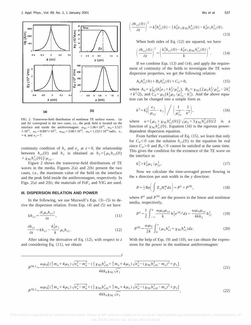
3 (0)#/myy .Figure 2 shows the transverse-field distributions of TE
waves in the media. Figures 2~a! and 2~b! present the twocases, i.e., the maximum value of the field on the interfaceand the peak field inside the antiferromagnet, respectively. InFigs. 2~a! and 2~b!, the materials of FeF2 and YIG are used.
III. DISPERSION RELATION AND POWER
In the following, we use Maxwell’s Eqs.~3!–~5! to de-rive the dispersion relation. From Eqs.~4! and ~5! we have
khx15]~mzhz1!
]z, ~11!
]hx1
]z5khz12
k02«1
kmzhz1 . ~12!
After taking the derivative of Eq.~12!, with respect tozand considering Eq.~11!, we obtain
S ]hx1~0!
]z D 2
5k12hz1
2 ~0!2 12 k0
2«1xNLhz14 ~0!2k0
2«1hx12 ~0!.
~13!
When both sides of Eq.~12! are squared, we have
S ]hx1~0!
]z D 2
5S k12hz1~0!2k0
2«1xNLhz13 ~0!
k D 2
. ~14!
If we combine Eqs.~13! and~14!, and apply the require-ment of continuity of the fields to investigate the TE wavedispersion properties, we get the following relation:
A0hz14 ~0!1B0hz1
2 ~0!1C050, ~15!
whereA05xNL2 (k0
2«11k22/myy
2 ), B05xNL(2mLk22/myy
2 22k12
1k2/2), andC05mL(k22mL /mxx
2 2k12). And the above equa-
tion can be changed into a simple form as
k25k02S «2
myy2«1D Y S 1
myy2 2
1
u2D , ~16!
where u5@mL1xNLhz12 (0)#/AmL13xNLhz1
2 (0)/2 is afunction of xNLhz1
2 (0). Equation~16! is the rigorous power-dependent dispersion equation.
From further examination of Eq.~15!, we learn that onlyfor C0,0 can the solutionhz1(0) to the equation be realsinceC0.0 andB0,0 cannot be satisfied at the same time.This gives the condition for the existence of the TE wave onthe interface as
k12.k2
2mL /myy2 . ~17!
Now we calculate the time-averaged power flowing inthe x direction per unit width in they direction:
P5 12 ReS E EyHz* dzD5PL1PNL, ~18!
wherePL andPNL are the powers in the linear and nonlinearmedia, respectively,
PL51
2 E2`
0 vm0myy
kh2
2e2k2zdz5vm0myy
4kk2h2
2, ~19!
PNL5vm0
2k E0
`
~mLhz12 1xNLhz1
4 !dz. ~20!
With the help of Eqs.~9! and~10!, we can obtain the expres-sions for the power in the nonlinear antiferromagnet:
PNL15vm0@~ 9
2 ma14mL!Ana22ma
22~ 32 xNLhz10
2 1 92 ma14mL!Ana
22~xNLhz102 2ma!21p1#
4kk0xNLA«1
, ~21!
PNL25vm0@~ 9
2 ma14mL!Ana22ma
21~ 32 xNLhz10
2 1 92 ma14mL!Ana
22~xNLhz102 2ma!21p2#
4kk0xNLA«1
, ~22!
FIG. 2. Transverse-field distribution of nonlinear TE surface waves.~a!and ~b! correspond to the two cases, i.e., the peak field is located on theinterface and inside the antiferromagnet:vM151.0631010, vA53.51731012, vC58.89731012, vM253.0831010, v051.23231010 rad/s, «1
54, and«257.
537J. Appl. Phys., Vol. 89, No. 1, 1 January 2001 Wu et al.
[This article is copyrighted as indicated in the article. Reuse of AIP content is subject to the terms at: http://scitation.aip.org/termsconditions. Downloaded to ] IP:
140.254.87.149 On: Sat, 20 Dec 2014 03:53:36
where
p15~ 32 na
213ma214mLma1mL
2!
3Fsin21S ma
naD2sin21S ma2xNLhz10
2
naD G ,
p25~ 32na
213ma214mLma1mL
2!
•Fp1sin21S ma
naD1sin21S ma2xNLhz10
2
naD G .
PNL1 denotes the power in the antiferromagnet in the casethat the maximum field is on the interface whilePNL2 de-notes the power in the case that the peak field lies inside theantiferromagnet.
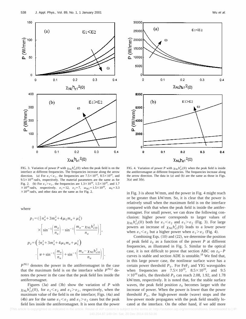
Figures ~3a! and ~3b! show the variation ofP withxNLhz1
2 (0), for «1,«2 and «1.«2 , respectively, when themaximum value of the field is on the interface; Figs.~4a! and~4b! are for the same«1,«2 and«1.«2 cases but the peakfield lies inside the antiferromagnet. It is seen that the power
in Fig. 3 is about W/mm, and the power in Fig. 4 might reachor be greater than kW/mm. So, it is clear that the power isrelatively small when the maximum field is on the interfacecompared with that when the peak field is inside the antifer-romagnet. For small power, we can draw the following con-clusion: higher power corresponds to larger values ofxNLhz1
2 (0) both for «1,«2 and «1.«2 ~Fig. 3!. For largepowers an increase ofxNLhz1
2 (0) leads to a lower powerwhen«1,«2 but a higher power when«1.«2 ~Fig. 4!.
Combining Eqs.~10! and~22!, we determine the positionof peak fieldz0 as a function of the powerP at differentfrequencies, as illustrated in Fig. 5. Similar to the opticalcase, it is not difficult to prove that section ABC onz0–Pcurves is stable and section ADE is unstable.18 We find that,in this large power case, the nonlinear surface wave has acertain power thresholdP0 . For FeF2 and YIG waveguideswhen frequencies are 7.531010, 8.531010, and 9.531010rad/s, the thresholdP0 can reach 2.08, 1.92, and 1.78kW/mm, respectively. It is noted that, for the stable surfacewaves, the peak field positionz0 becomes larger with theincrease of power. When the power is lower than the powerthresholdP0 , the high-power mode~wave! stops and thelow-power mode propagates with the peak field steadily lo-cated at the interface. On the other hand, if we add more
FIG. 3. Variation of powerP with xNLhz12 (0) when the peak field is on the
interface at different frequencies. The frequencies increase along the arrowdirection. ~a! For «1,«2 , the frequencies are 7.531010, 8.531010, and9.531010 rad/s, respectively. The material parameters are the same as forFig. 2. ~b! For «1.«2 , the frequencies are 1.331010, 1.531010, and 1.731010 rad/s, respectively.«1512, «257, vM251.531010, v053.331010 rad/s, and other data are the same as for Fig. 2.
FIG. 4. Variation of powerP with xNLhz12 (0) when the peak field is inside
the antiferromagnet at different frequencies. The frequencies increase alongthe arrow direction. The data in~a! and ~b! are the same as those in Figs.3~a! and 3~b!.
538 J. Appl. Phys., Vol. 89, No. 1, 1 January 2001 Wu et al.
[This article is copyrighted as indicated in the article. Reuse of AIP content is subject to the terms at: http://scitation.aip.org/termsconditions. Downloaded to ] IP:
140.254.87.149 On: Sat, 20 Dec 2014 03:53:36
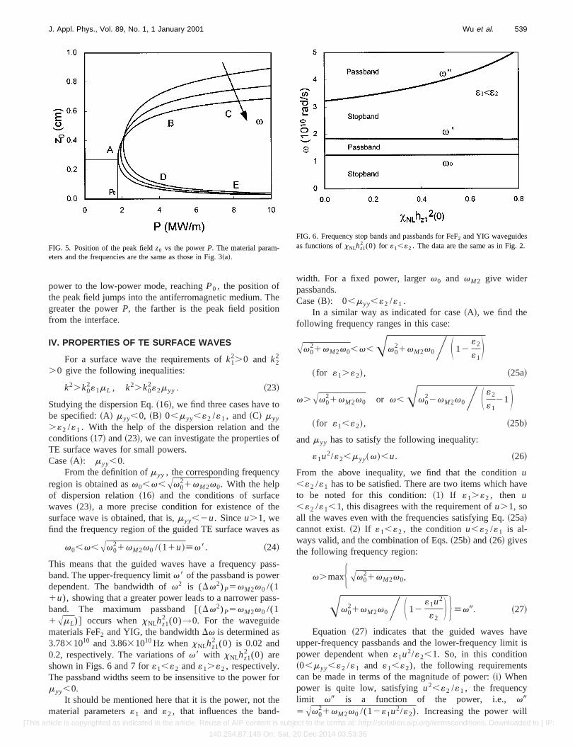
power to the low-power mode, reachingP0 , the position ofthe peak field jumps into the antiferromagnetic medium. Thegreater the powerP, the farther is the peak field positionfrom the interface.
IV. PROPERTIES OF TE SURFACE WAVES
For a surface wave the requirements ofk12.0 and k2
2
.0 give the following inequalities:
k2.k02«1mL , k2.k0
2«2myy . ~23!
Studying the dispersion Eq.~16!, we find three cases have tobe specified:~A! myy,0, ~B! 0,myy,«2 /«1 , and~C! myy
.«2 /«1 . With the help of the dispersion relation and theconditions~17! and~23!, we can investigate the properties ofTE surface waves for small powers.Case~A!: myy,0.
From the definition ofmyy , the corresponding frequencyregion is obtained asv0,v,Av0
21vM2v0. With the helpof dispersion relation~16! and the conditions of surfacewaves ~23!, a more precise condition for existence of thesurface wave is obtained, that is,myy,2u. Sinceu.1, wefind the frequency region of the guided TE surface waves as
v0,v,Av021vM2v0 /~11u![v8. ~24!
This means that the guided waves have a frequency pass-band. The upper-frequency limitv8 of the passband is powerdependent. The bandwidth ofv2 is (Dv2)P5vM2v0 /(11u), showing that a greater power leads to a narrower pass-band. The maximum passband@(Dv2)P5vM2v0 /(11AmL)# occurs whenxNLhz1
2 (0)→0. For the waveguidematerials FeF2 and YIG, the bandwidthDv is determined as3.7831010 and 3.8631010Hz whenxNLhz1
2 (0) is 0.02 and0.2, respectively. The variations ofv8 with xNLhz1
2 (0) areshown in Figs. 6 and 7 for«1,«2 and«1.«2 , respectively.The passband widths seem to be insensitive to the power formyy,0.
It should be mentioned here that it is the power, not thematerial parameters«1 and «2 , that influences the band-
width. For a fixed power, largerv0 and vM2 give widerpassbands.Case~B!: 0,myy,«2 /«1 .
In a similar way as indicated for case~A!, we find thefollowing frequency ranges in this case:
Av021vM2v0,v,Av0
21vM2v0Y S 12«2
«1D
~ for «1.«2!, ~25a!
v.Av021vM2v0 or v,Av0
22vM2v0Y S «2
«121D
~ for «1,«2!, ~25b!
andmyy has to satisfy the following inequality:
«1u2/«2,myy~v!,u. ~26!
From the above inequality, we find that the conditionu,«2 /«1 has to be satisfied. There are two items which haveto be noted for this condition:~1! If «1.«2 , then u,«2 /«1,1, this disagrees with the requirement ofu.1, soall the waves even with the frequencies satisfying Eq.~25a!cannot exist.~2! If «1,«2 , the conditionu,«2 /«1 is al-ways valid, and the combination of Eqs.~25b! and~26! givesthe following frequency region:
v.maxHAv021vM2v0,
Av021vM2v0Y S 12
«1u2
«2D J [v9. ~27!
Equation ~27! indicates that the guided waves haveupper-frequency passbands and the lower-frequency limit ispower dependent when«1u2/«2,1. So, in this condition~0,myy,«2 /«1 and «1,«2), the following requirementscan be made in terms of the magnitude of power:~i! Whenpower is quite low, satisfyingu2,«2 /«1 , the frequencylimit v9 is a function of the power, i.e., v95Av0
21vM2v0 /(12«1u2/«2). Increasing the power will
FIG. 5. Position of the peak fieldz0 vs the powerP. The material param-eters and the frequencies are the same as those in Fig. 3~a!.
FIG. 6. Frequency stop bands and passbands for FeF2 and YIG waveguidesas functions ofxNLhz1
2 (0) for «1,«2 . The data are the same as in Fig. 2.
539J. Appl. Phys., Vol. 89, No. 1, 1 January 2001 Wu et al.
[This article is copyrighted as indicated in the article. Reuse of AIP content is subject to the terms at: http://scitation.aip.org/termsconditions. Downloaded to ] IP:
140.254.87.149 On: Sat, 20 Dec 2014 03:53:36
lead to a narrower passband and could stop the waves whichare originally propagating in the system. The variation ofv9with xNLhz1
2 (0) is shown in Fig. 6.~ii ! When the powerbecomes larger andu2.«2 /«1 , v9 is no longer power de-pendent (v95Av0
21vM2v0) and the passband width isconstant within a certain power range.~iii ! Further increasingthe power, higher than the threshold, until the inequalityu.«2 /«1 is satisfied, then the waves in the frequency regimegiven by Eq.~27! stop.Case~C!: myy.«2 /«1 .
This case corresponds to the following inequalities:
v,v0 or v.Av021vM2v0Y S 12
«2
«1D ~«1.«2!,
~28a!
v0.v.Av021vM2v0Y S 12
«2
«1D ~«1,«2!. ~28b!
Combining the dispersion Eq.~16! and the conditions ofsurface waves~17! and ~23!, we obtain the existence condi-tion u.«2 /«1 , and myy must satisfy «1u2/«2.myy(v).u.
~i! When«1.«2 , the nonlinear TE surface waves propa-gate in the frequency region
v,Av021vM2v0 /~12«1u2/«2![v-. ~29!
That is, the guided waves have a lower-frequency passbandthat is not only power dependent but also material-parameterdependent. An increase of power leads to a biggerv- and awider passband. The variation ofv- with xNLhz1
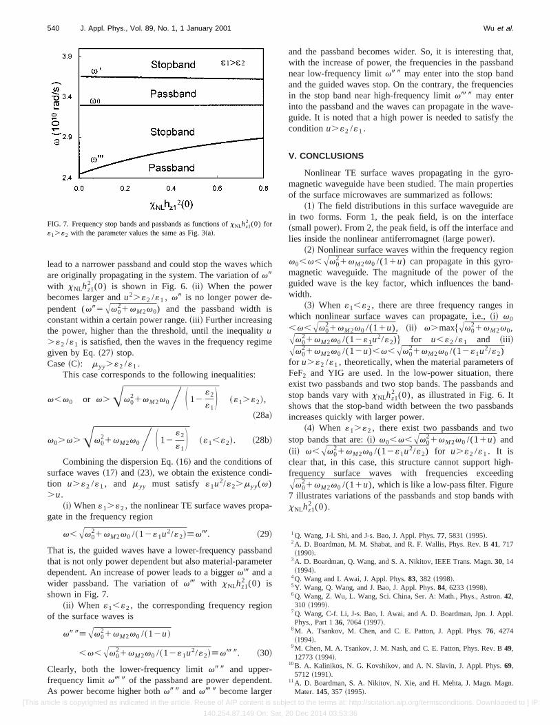
2 (0) isshown in Fig. 7.
~ii ! When «1,«2 , the corresponding frequency regionof the surface waves is
v9 9[Av021vM2v0 /~12u!
,v,Av021vM2v0 /~12«1u2/«2![v- 9. ~30!
Clearly, both the lower-frequency limitv9 9 and upper-frequency limitv- 9 of the passband are power dependent.As power become higher bothv9 9 andv- 9 become larger
and the passband becomes wider. So, it is interesting that,with the increase of power, the frequencies in the passbandnear low-frequency limitv9 9 may enter into the stop bandand the guided waves stop. On the contrary, the frequenciesin the stop band near high-frequency limitv- 9 may enterinto the passband and the waves can propagate in the wave-guide. It is noted that a high power is needed to satisfy theconditionu.«2 /«1 .
V. CONCLUSIONS
Nonlinear TE surface waves propagating in the gyro-magnetic waveguide have been studied. The main propertiesof the surface microwaves are summarized as follows:
~1! The field distributions in this surface waveguide arein two forms. Form 1, the peak field, is on the interface~small power!. From 2, the peak field, is off the interface andlies inside the nonlinear antiferromagnet~large power!.
~2! Nonlinear surface waves within the frequency regionv0,v,Av0
21vM2v0 /(11u) can propagate in this gyro-magnetic waveguide. The magnitude of the power of theguided wave is the key factor, which influences the band-width.
~3! When «1,«2 , there are three frequency ranges inwhich nonlinear surface waves can propagate, i.e.,~i! v0
,v,Av021vM2v0 /(11u), ~ii ! v.max$Av0
21vM2v0,Av0
21vM2v0 /(12«1u2/«2)% for u,«2 /«1 and ~iii !Av0
21vM2v0 /(12u),v,Av021vM2v0 /(12«1u2/«2)
for u.«2 /«1 , theoretically, when the material parameters ofFeF2 and YIG are used. In the low-power situation, thereexist two passbands and two stop bands. The passbands andstop bands vary withxNLhz1
2 (0), asillustrated in Fig. 6. Itshows that the stop-band width between the two passbandsincreases quickly with larger power.
~4! When «1.«2 , there exist two passbands and twostop bands that are:~i! v0,v,Av0
21vM2v0 /(11u) and~ii ! v,Av0
21vM2v0 /(12«1u2/«2) for u.«2 /«1 . It isclear that, in this case, this structure cannot support high-frequency surface waves with frequencies exceedingAv0
21vM2v0 /(11u), which is like a low-pass filter. Figure7 illustrates variations of the passbands and stop bands withxNLhz1
2 (0).
1Q. Wang, J-l. Shi, and J-s. Bao, J. Appl. Phys.77, 5831~1995!.2A. D. Boardman, M. M. Shabat, and R. F. Wallis, Phys. Rev. B41, 717~1990!.
3A. D. Boardman, Q. Wang, and S. A. Nikitov, IEEE Trans. Magn.30, 14~1994!.
4Q. Wang and I. Awai, J. Appl. Phys.83, 382 ~1998!.5Y. Wang, Q. Wang, and J. Bao, J. Appl. Phys.84, 6233~1998!.6Q. Wang, Z. Wu, L. Wang, Sci. China, Ser. A: Math., Phys., Astron.42,310 ~1999!.
7Q. Wang, C-f. Li, J-s. Bao, I. Awai, and A. D. Boardman, Jpn. J. Appl.Phys., Part 136, 7064~1997!.
8M. A. Tsankov, M. Chen, and C. E. Patton, J. Appl. Phys.76, 4274~1994!.
9M. Chen, M. A. Tsankov, J. M. Nash, and C. E. Patton, Phys. Rev. B49,12773~1994!.
10B. A. Kalinikos, N. G. Kovshikov, and A. N. Slavin, J. Appl. Phys.69,5712 ~1991!.
11A. D. Boardman, S. A. Nikitov, N. Xie, and H. Mehta, J. Magn. Magn.Mater.145, 357 ~1995!.
FIG. 7. Frequency stop bands and passbands as functions ofxNLhz12 (0) for
«1.«2 with the parameter values the same as Fig. 3~a!.
540 J. Appl. Phys., Vol. 89, No. 1, 1 January 2001 Wu et al.
[This article is copyrighted as indicated in the article. Reuse of AIP content is subject to the terms at: http://scitation.aip.org/termsconditions. Downloaded to ] IP:
140.254.87.149 On: Sat, 20 Dec 2014 03:53:36
12A. D. Boardman, S. A. Nikitov, and O. Wang, IEEE Trans. Magn.30, 1~1994!.
13N. S. Almeida and D. L. Mills, Phys. Rev. B36, 2015~1987!.14S. Vukovich, S. N. Gavrilin, and S. A. Nikitov, Sov. Phys. JETP71, 964
~1991!.15J. W. Boyle, S. A. Nikitov, A. D. Boardman, J. G. Booth, and K. Booth,
Phys. Rev. B53, 12173~1996!.
16D. Mihalache, G. I. Stegeman, C. T. Seaton, E. M. Wright, R. Zanoni, A.D. Boardman, and T. Twardowski, Opt. Lett.12, 187 ~1987!.
17Q. Wang, Y.-F. Wang, and J.-S. Bao, Acta Phys. Sin.45, 142~1997!.
18A. C. Newell and J. V. Moloney,Nonlinear Optics~Addison-Wesley,New York, 1991!. 120–146.
541J. Appl. Phys., Vol. 89, No. 1, 1 January 2001 Wu et al.
[This article is copyrighted as indicated in the article. Reuse of AIP content is subject to the terms at: http://scitation.aip.org/termsconditions. Downloaded to ] IP:
140.254.87.149 On: Sat, 20 Dec 2014 03:53:36