microscope status, mission definition and ... - ggi.infn.it · • maxi power with less solar...
TRANSCRIPT

MICROSCOPE status, mission definition and recent instrument development
“The ratio of the masses of two bodies is defined in two ways which differ from each other fundamentally,…, as the reciprocal ratio of the accelerations which the same motive force imparts to them (inert mass),…, as the ratio of the forces which act upon them in the same gravitational field (gravitational mass). The equality of these two masses, so differently defined, is a fact which is confirmed by experiments…The possibility of explaining the numerical equality of inertia and gravitation by the unity of their nature, gives to the general theory of relativity, according to my conviction, such a superiority over the conception of classical mechanics…”
A. EINSTEIN The Meaning of Relativity, Princeton,

PIER
RE
TOU
BO
UL
-GR
EX ,F
lore
nce
–se
pt 0
6 –
2
SELECTED IN CNES NATIONAL SCIENTIFIC PROGRAMwith ESA COOPERATION
CNES SMALL SATELLITE MISSION
ESA THRUSTERS
MISSION PROPOSED BY ONERA (Pi) & OCA (Co-Pi) with ZARM (Co-I)
Jan – April 2006 :Preliminary Design Review of the Instrument,the Satellite, the Mission (End of Phase B)
Launch expected in 09-10 depending on Feeps.
Thanks to Gilles Métris and his team (OCA),to Hans Dittus and his team (ZARM),to Jean Bernard Dubois and his team (CNES),to Davide Nicolini and his team (ESA) to GREX for scientific supports, exchanges and emulations
Activities supports and Funding from CNES and Institutes
THE MICROSCOPE MISSIONZ
X
Y
µsatspin
Courtesy CNES
“The ratio of the masses of two bodies is defined in two ways which differ from each other fundamentally,…, as the reciprocal ratio of the accelerations which the same motive force imparts to them (inert mass),…,as the ratio of the forces which act upon them in the same gravitational field (gravitational mass).The equality of these two masses, so differently defined, is a fact which is confirmed by experiments…

PIER
RE
TOU
BO
UL
-GR
EX ,F
lore
nce
–se
pt 0
6 –
3Equivalence Principle
• Quantum Theory, Standard ModelElectromagnetism, Strong & Weak Nuclear Force
• Geometric Theory of Gravitation, GR
Super Symmetry requires new particles...Super String Theory, Branes… requires new field…
⇒ Galaxy rotation Dark matter ? 25%
⇒ Universe Expansion acceleration Dark Energy ? 70%
Domain of validity for current theories to be always confirmed more accurately
Many proposed space experiments:• Lorentz Invariance test :PHARAO, LATOR,…• Post-Newtonian Parameters accurate
determination : GPB, PHARAO,...• Determination and observation of
relativistic effects : GPB, LISA, ASTROD, …• Stability of ‘Constants’
1700 19001800 2000
10-3
10-5
10-7
10-9
10-11
10-13
10-15
MICROSCOPE
STEP objective 10-18
GG objective 10-17
1
1
2
2
I
g
I
g
mm
mm
δ −=Equivalence Principle Tests (by UFF test) directly verify a fundamental basis ofour present Gravity knowledge & may confirm dilaton existence
The possibility of explaining the numerical equality of inertia and gravitation by the unity of their nature, gives to the general theory of relativity, according to my conviction, such a superiority over the conception of classical mechanics…”A. EINSTEIN The Meaning of Relativity, Princeton,

PIER
RE
TOU
BO
UL
-GR
EX ,F
lore
nce
–se
pt 0
6 –
4A Mission concept relying on best current technologies and models
DEMETER launched in 2004
CNES micro satellite ONERA Accelerometer
GRACE EM & GOCE FM accelero.during qualification tests 06
OCA Space Geodesy & Astrometry
Jason altimetry
MICROSCOPE FEEP
ESA FEEP Pos Det ADC ControlLaws
DAC
DVA
ADC
Drag Free Control
Science Data Output
PM
++
-1

PIER
RE
TOU
BO
UL
-GR
EX ,F
lore
nce
–se
pt 0
6 –
5
GOCE FM tests in lab. (Jul 06)
Noise FM03 Axis Z
1,E-08
1,E-07
1,E-06
1,E-05
1,E-02 1,E-01 1,E+00Frequency (Hz)
m.s
-2.H
z-1/
2
Gradio DM1
ASH FM03GOCE ESA mission :• 6 Electrostatic accelerometers for the full tensor gravity gradiometerTests on horizontally controlled table

PIER
RE
TOU
BO
UL
-GR
EX ,F
lore
nce
–se
pt 0
6 –
6A Mission concept relying on best current technologies and models
DEMETER launched in 2004
CNES micro satellite OCA Space Geodesy & Astrometry
Jason altimetry
MICROSCOPE FEEP
ESA FEEP Pos Det ADC ControlLaws
DAC
DVA
ADC
Drag Free Control
Science Data Output
PM
++
-1
ONERA AccelerometerZARM drop tower

PIER
RE
TOU
BO
UL
-GR
EX ,F
lore
nce
–se
pt 0
6 –
7
Free fall tests in ZARM
ZARM drop tower
Comparison between GRACE and GOCE inst.along vertical
2.10-12 ms-2/Hz1/2 from 5 to 100 mHz

PIER
RE
TOU
BO
UL
-GR
EX ,F
lore
nce
–se
pt 0
6 –
8
A family of space accelerometers• Γn :3·10-9 ms-2 /Hz1/2
• Γmax :10-4 ms-2
• [2·10-4; 10-1 ]Hz
•One in orbit from Jul 00
• Γn :10-10 ms-2 /Hz1/2
• Γmax : 5·10-5 ms-2
• [10-4; 10-1 ]Hz
•Two in orbit from Mar 02
• Γn : 2·10-12 ms-2 /Hz1/2
• Γmax : 6·10-6 ms-2
• [5·10-3; 10-1 ]Hz
• to be launched in 07
MICROSCOPE
• Γn : < 3.10-15 ms-2 @ fEP
• Γmax : 3.10-8 ms-2
• [10-4; 4.10-3 ]Hz
ASTREMicrogravity sensor
1 mg down to 3 nanog3 schuttle flights in 95-96

PIER
RE
TOU
BO
UL
-GR
EX ,F
lore
nce
–se
pt 0
6 –
9A Mission concept relying on best current technologies and models
DEMETER launched in 2004
CNES micro satelliteONERA AccelerometerZARM drop tower OCA Space
Geodesy & Astrometry
Jason altimetry
MICROSCOPE FEEP
ESA FEEP

PIER
RE
TOU
BO
UL
-GR
EX ,F
lore
nce
–se
pt 0
6 –
10A Mission concept relying on best current technologies and models
DEMETER launched in 2004
CNES micro satellite OCA Space Geodesy & Astrometry
Jason altimetry
MICROSCOPE FEEP
ESA FEEP
ONERA AccelerometerZARM drop tower

PIER
RE
TOU
BO
UL
-GR
EX ,F
lore
nce
–se
pt 0
6 –
11MICROSCOPE Test Principle
• Earth : Gravity Source• Two pairs of masses
made of different composition in free fall• Test: Pt/Ti• Reference : Pt/Pt
• Maintained on the same orbit (<10-11m)by electrostatic forces
Test measurement•Low noise:
• Long duration integration (>20 orbits)& numerous measures
• Drag compensated satellite• Very clean thermal environment
•EP violation signal well defined•Phase: attitude wrt position in orbit•Frequency: forb + fspin
soep fff +=
Material 1 (Pt)Material 2 (Ti)
Measurement Axis
Optional Spin
Pt
Ti
B/μ Z/μ (N-Z)/μ
1.008911 0.46309 0.082731.008009 0.40296 0.20208
Test accuracy : δ = 10-15
Specified per session of 1 day to 1 weekMission duration : 1 year

PIER
RE
TOU
BO
UL
-GR
EX ,F
lore
nce
–se
pt 0
6 –
12
The Orbit
Pointing•Inertial or rotating satellite :2 spin freq. : (π +1/2) forb & (π +3/2) forb
•Finely controlled requiring Attitude Estimator from SST &Instrument data, up to a few 0.1 µrad :sensitive to S/C thermal behavior
Satellite altitude• 730 or 790 km : Larger signal
Less radiation (electronics)Higher forb
(to 1400 km : No eclipse, Less thermal disturbance)
•Position to be known from 7 m, 14 m to 100m (for Earth gravity gradient corrections)
HELIOSYNCHRONOUS• Thermal stability• Maxi power with less solar panels(stiff S/C : high frequency modes)• No eclipse during measurement phase
QUASI-CIRCULAR & POLAR• Eccentricity < 5.10-3
To limit Earth gravity gradient (Egg) @ fEP
• Known better than 5. 10-5
To correct measurements from Egg effects

PIER
RE
TOU
BO
UL
-GR
EX ,F
lore
nce
–se
pt 0
6 –
13
A satellite coming from MYRIADE line
Battery
1inertial wheel
ICUME
PCDUOBC
SST ElectronicsµDPU BCU
RX/TX2
Magnetotorquer
SU REF & SU EP
Desorbitation system
+Z
+Y
+X
FEEU
RX/TX1
Pyro
SSTEPSA
SAS
No gyros
With Cnes Courtesy

PIER
RE
TOU
BO
UL
-GR
EX ,F
lore
nce
–se
pt 0
6 –
14Electric Propulsion System : Baseline ConfigurationElectric Propulsion System : Baseline Configurationfor the dragfor the drag--free controlfree control
4 Electric Propulsion SubsystemAssembly, Cluster of 3 FEEP thrustersCesium FEEP
=> Specific constraints & ElectrostaticDischarge risk• EPS total mass = 41 kg• Average power ~100 W (@ 30 µN) • Maximum power = 4 x 53 W = 212 W
EPS: ESA
EPSA: ALTA (prime)PPCU: Galileo AvionicaNA: AAS ProelPMD: Astrium SASLOM: Contraves Space
Drag free system specs : 3.10-10 ms-2Hz-1/2 along 3 axes10-12 ms-2 @ fEP

PIER
RE
TOU
BO
UL
-GR
EX ,F
lore
nce
–se
pt 0
6 –
15Alternate Solutions
Proportional cold gas thruster :Interest :• relatively simple ⇒ reliability• reduced power consumption 50 W (reduced solar panel area : x 0.6)Drawbacks:small Isp ⇒ mass increase : + 20kg
Indium FEEP :Interest:• low interaction with water vapor• testedDrawbacks:limited thrust (50 µN) ⇒ clusters⇒ weight and power very high for microsatellite
back-up with double solar panels
Possible back-upMarotta UK
AAS (Laben)

PIER
RE
TOU
BO
UL
-GR
EX ,F
lore
nce
–se
pt 0
6 –
16
274×171×90 mm3 x 3.5kg x 2
255 x 200 x 110 mm3 x 7kg
360 x 348 x 180 mm3 x 20kg
Instrument Description2 identical instruments cores, Sensor Units (SU) =
2 Electrostatic Differential AccelerometersEach = 2 Inertial sensors with two concentric masses
2 identical Front End Electronics Units (FEEU)• Low noise/ High stability Analog Electronics• 2 X 6 electrostatic channels + measurements
2 Interface Control Unit (ICU) stacked • Digital Logics and Electronics 1 DSP + 2 FPGA• Power Control Unit with very stable secondary
voltages (+/-45V, +/-15V,+5V, + 3.3V)• Control laws, S/C data bus interfaces

PIER
RE
TOU
BO
UL
-GR
EX ,F
lore
nce
–se
pt 0
6 –
17SensorSensor Head Head TechnologyTechnology
SIO2 materialOptical grindingUltrasonic machiningGold coating by RF diode sputteringClean room integration High vacuum housing and magnetic
shieldingmicrometer, arc second accuracies
SIO2 materialOptical grindingUltrasonic machiningGold coating by RF diode sputteringClean room integration High vacuum housing and magnetic
shieldingmicrometer, arc second accuracies

PIER
RE
TOU
BO
UL
-GR
EX ,F
lore
nce
–se
pt 0
6 –
18
SensorSensor UnitUnitChallenging new technology :
- Cylindrical Shapes (mass, electrodes)- Accuracy of mass and electrode cylinder geometries-2 concentric sensors & Relative positioning and centering-Ultra-vacuum technology for connectors and gaskets- Blocking mechanism-Integration procedures
Challenging new technology :- Cylindrical Shapes (mass, electrodes)- Accuracy of mass and electrode cylinder geometries-2 concentric sensors & Relative positioning and centering-Ultra-vacuum technology for connectors and gaskets- Blocking mechanism-Integration procedures
10-5 Pa
2.7 106 Pa
36 x 35 x 18 cm3
PIER
RE
TOU
BO
UL
-GR
EX ,F
lore
nce
–se
pt 0
6 –
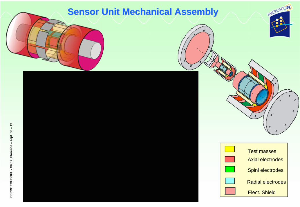
19SensorSensor Unit Unit MechanicalMechanical AssemblyAssembly
Radial electrodes
Elect. Shield
Spinl electrodes
Axial electrodesTest masses

PIER
RE
TOU
BO
UL
-GR
EX ,F
lore
nce
–se
pt 0
6 –
20
Instrument Development
Lab model : Sensor core• 1 test-mass in silica (15g)
Lab model : Electronics• Analog sensing and control• 300 V to 800 V for 1g levitation
2004-2008
2006MR-VIB : Sensor core2 TM in W alloy
Electrostatic control loop for coupling and stiffness assessment
Vibration tests for design assessmentIntegration process development
Z ( µm )
t ( s )
dB
Hz

PIER
RE
TOU
BO
UL
-GR
EX ,F
lore
nce
–se
pt 0
6 –
21
SU Prototype, production SU Prototype, production
Integration procedures5µm diameter gold wires, implementation. Silica parts, positioning and alignment.Blocking forces, adequate.
VibrationsResonances identified at specific vibration frequencies ( ≈ 700 Hz)Blocking mechanism compatible with the up- dated vibration levels Blocking mechanism tank successfully tested with over- pressure of 100bars

PIER
RE
TOU
BO
UL
-GR
EX ,F
lore
nce
–se
pt 0
6 –
22Front End Front End ElectronicsElectronics Unit Unit
FEEU: accurate analog electronics functions• test mass position sensing• actuations• reference voltages generation• HK data measurement
Budget : • Volume : 274×171×89.50 mm3
• Mass (EM) : 3.045 kg• Power : 6.4 W
6 capacitive position sensors5×10-19 F/Hz1/2
6 pairs of Drive Voltage Amplifiers2×10-7 V/Hz1/2
-Reference voltage sources (Vp, Vd) - Housekeepingdata
-Digital interface with ICU (FPGA, drivers)

PIER
RE
TOU
BO
UL
-GR
EX ,F
lore
nce
–se
pt 0
6 –
23
Performance drivers (1/3)
• S/C position tracking (Doppler) : < 23m, < 23m, 100m accuracy @ fep
• Attitude Control : •Pointing : 10-3 rad with variations < 24 µrad (inertiel) & 0.4 µrad (spin) @ fep•Angular velocity variations < 2.5 10-9 rad/s (spin) @ fep•Angular accelerations variations < 2.3 10-11 rad/s² (inertial)
&1.5 10-11 rad/s² (spin) @ fep
• Drag-Free Control : < 3.10-10ms-2Hz-1/2 noise and < 10-12ms-2 variations @ fep
Results from definitions and simulations presented at Cnes satellite PDR
( )( ) knlzyxl
ltkappkapplkappkkkmeas uuKuMK ,
,,,,2,,0, Γ+⋅⋅Γ⋅Γ⋅⋅+Γ⋅+≈Γ ∑
=
rrrrrr
( )2,1,, 2/1 appappdapp Γ−Γ⋅=Γrrr
[ ] [ ]( )( )Δ⋅−+⋅⋅≈Γrrr
InTOg satdapp )(2/1, δ
[ ] [ ]( ) satksatIk
gksat
I
g
I
ngkapp OOInTOg
mm
OgMM
MF
⋅−+⋅−⋅+≈Γ )()(,rr
rr
sensor
Differential sensor
Gravity gradient
Instrument model

PIER
RE
TOU
BO
UL
-GR
EX ,F
lore
nce
–se
pt 0
6 –
24
Performance drivers (2/3)
Instrument characteristics and in-orbit calibration :
• Resolution : < 10-12ms-2Hz-1/2 and 10-9rads-2Hz-1/2
• Stability of sensitivity : < 6.8 10-8 sine (FEEU thermal effect) and 1.2 10-5 Hz-1/2 @ fep• SF matching : < 1.5 10-4
with stability : < 0.3 10-8 sine (SU thermal effect) and 3.10-6 Hz-1/2 @ fep• Alignment matching : < 5.10-5 radwith stability : <1.5 10-9 rad sine (SU thermal effect) and 3.10-7rad Hz-1/2 @ fep
Results from instrument & satellite definitions and simulations presented during instrument & mission PDR
{ [ ] [ ] [ ]dynamicsnonlinnoisebias
xxgIMxxx
xgg j
j
kccdj
j
kEP ++
++
⎥⎥⎦
⎤
⎢⎢⎣
⎡Δ
∂∂
+−Γ+Δ∧Ω+Δ∧Ω∧Ω−⎥⎥⎦
⎤
⎢⎢⎣
⎡Δ
∂∂
+≈Γ−Γ
⊗
.ˆˆ
)(
frame SSTin correction
centring-mis and
gradient gravity sEarth'frame SSTwrt
alignment-mis Instrument
Control Free Drag matchingAlignment TM
matchingfactor Scalecontrolmotion
Attitude
termsdisturbinggradient gravity
signal violationEP
21
434213213214444 34444 21
&
43421
θη
( )2,1,, 2/1 appappdapp Γ−Γ⋅=Γrrr
[ ] [ ]( ) satksatIk
gksat
I
g
I
ngkapp OOInTOg
mm
OgMM
MF
⋅−+⋅−⋅+≈Γ )()(,rr
rr

PIER
RE
TOU
BO
UL
-GR
EX ,F
lore
nce
–se
pt 0
6 –
25
Performance drivers (3/3)
Experiment EnvironmentMagnetic :
•< 10-4Am² variations @ fep to 0.3 m •Test-mass magnetic susceptibility :
XP t alloy= 2.8 10-4 ; XTi alloy = 7.1 10-5
•Shield from magnetic field and gradients,Obtained through Supranister case & INVAR SU tight housing (Tests realized in CNES and in ONERA lab.)
Self-gravity :•Variations of the self-gravity gradient specified < 10-11s-2
•Thermo-mechanics Finite Element Models + Temperature fluctuations 10 less gradients on the masses
Thermal accommodation :•1mK @ fep on SU at the unit interface•10mK/m @ fep on SU at the unit interface•10 mK @ fep on FEEU at the unit interface•1 K @ fep on ICU at the unit interface
Magnetic property characterized in Cnes lab
Cnes specific facility

PIER
RE
TOU
BO
UL
-GR
EX ,F
lore
nce
–se
pt 0
6 –
26Specific double insulation Payload Case for integration in the satellite
SU
FEEU
Thermal stability of SU & FEEU with passive insulation and anti-Sun radiator
CNES Thermal model being integrated before tests
FEEU radiator

PIER
RE
TOU
BO
UL
-GR
EX ,F
lore
nce
–se
pt 0
6 –
27
Instrument Thermal Model
From interface Temperature to relevant Temperature :Photons/Molecules therrmalized on gold coated silica surrounding massesTemperature filtered out @ fEP by a factor 5
100 x 10 mK p.top. sine variation @ interface=> 100 x 2mK p.top. sine variation on silica parts
3D finite elementsThermal model
3D finite elementsThermal model

PIER
RE
TOU
BO
UL
-GR
EX ,F
lore
nce
–se
pt 0
6 –
28
Temperature fluctuation Impact (SU)
Radiation pressure : < 3.2 10-16 ms-2 (worst case* @ fep)Difference of forces exerted on each test-mass by photons pressure when temperature difference varies on each side in regards to mass (ΔTSi)
Radiometer effect : < 2.2 10-16 ms-2 (worst case* @ fep)Difference of forces exerted on each test-mass by residual gas pressure Pg when temperature difference varies on each side in regards to mass (ΔTSi)
Outgassing : < 2.5 10-17 ms-2 (worst case* @ fep)Difference of forces exerted on each test-mass by variation of gaz pressure ΔPginduced by the outgassing of the gold coated silica parts
Gold Wire stiffness : thermal stability < 1.7 10-15ms-2 (worst case @ fep)Electrical link between mass and Voltage Reference : 5µm φ wirewhen temperature varies, Young Modulus varies
Worst case *: lower density mass & inertial pointing (lower fEP , thus less thermal filtering)
4Tc3
4Pr σ= S
TT4P
m1 Si
rn ⎟⎠⎞
⎜⎝⎛ Δ
=Γ
STTP
m1 Si
gn ⎟⎠⎞
⎜⎝⎛ Δ
=Γ
SPm1
gn Δ=Γ2Si
g TgradTP Δ
∝Δ
Si0wiren TTE
E1xk
m1
Δ⎟⎠⎞
⎜⎝⎛
∂∂
=Γ

PIER
RE
TOU
BO
UL
-GR
EX ,F
lore
nce
–se
pt 0
6 –
29
FEEU THERMAL VACUUM TESTS
Vp areaThermal response
Interface (1K step variation)
Thermal vacuum testsin CNES facility
Thermal Filtering focused on Vp reference voltage:factor 2 expected
Unit Power consumption fluctuations Spec : < 5 mW @ fep ; Verified : <3 mW
Tests performed in Cnes facilitywith the Onera FEEU EM

PIER
RE
TOU
BO
UL
-GR
EX ,F
lore
nce
–se
pt 0
6 –
30
Temperature Fluctuation Impact :major effects
Electrostatic stiffness & bias force :Thermal stability < 1.8 10-15 + 1.10-15 ms-2 (worst case @ fep)
• Bias due to geometrical dissymetry (Cylindricity, electrode geometry,…) orto electrical dissymmetry (capacitive sensor position offset ΔCSoffset, …)
Scale factor stability :< 6.5 10-6 K-1 , effect depending on S/C drag compensation system performance
• Due to Vp stability (40µV/K) and to ADC reference source stability (30µV/K)• Interest of thermal insulation of these circuits wrt unit interface • Interest of regulated power line and steady power consumption
Thermal variations mainly due to Reference Voltage source :being improved by an expected factor 4 with up-dated components
( )FEEU
dpcylindgeometry T
TVV
gapABias Δ
∂
+∂⎥⎦
⎤⎢⎣
⎡Δ≈Δ
22CSoffsetFEEU
elec TT
Bias ΔΔ⎟⎟⎠
⎞⎜⎜⎝
⎛∂
∂≈Δ
44 344 21
s variationstiffnessticElectrosta
2ω
KµVTVp /40=⎟⎟
⎠
⎞⎜⎜⎝
⎛∂
∂

PIER
RE
TOU
BO
UL
-GR
EX ,F
lore
nce
–se
pt 0
6 –
31Mission Performances : Mission Performances : RotatingRotating satellite session : satellite session : ffEPEP = (= (ΠΠ+3/2) +3/2) fforborb ~ 8 . 10~ 8 . 10--44HzHz
• More than 70 error terms taken into account :•Bias : 18, noise : 17, sf : 1 •Temperature sensitivity : 30 + 3 ; thermal gradient sensitivity : 3•Magnetism : 2
•Major terms
• BudgetTotal random errors : B = 1.6 10-12 ms-2/Hz-1/2
integration duration : Ti = 20 orbits @ h = 730km4 major tone errors : D = 4.9 10-15 ms-2
(D = 2.5 10-15 ms-2 with quad. sum)
Value compatible with the specification : 1 x 10-15 per sessionAt least 50 sessions during the 1 year mission
15
22
109.0)(
−×=+
=HgTBDiη
Random ms-2/Hz1/2 Coriolis (differential mode) 5.12 E-13 PM Motion (differential mode) 3.11 E-13 Accelerometer measurement noise 1.34 E-12 Bias sensitivity to thermal gradient variation 3.75 E-13
Tone @ fep ms-2
Coriolis (differential mode) 1.71 E-15 PM motion (differential mode) 1.04 E-15 PM position (differential mode) 8.68 E-16 Bias sensitivity to thermal gradient variation 1.25 E-15
Invar thermal fluctuationsPositioning InstabilitiesMass DampingRadiation & Radiometer
Invar thermal fluctuationsPositioning Instabilities[Τ−Ω2]Radiation & Radiometer

PIER
RE
TOU
BO
UL
-GR
EX ,F
lore
nce
–se
pt 0
6 –
32
Conclusion
Payload & Satellite definition achievedPDRs conclude with no mission stopping items
but 6-12 months needed more to assess FEEP or other solution,Instrument : SU definition can be still optimized :for resistance to vibration : according to selected launcher requirementsfor thermal stability : SU Temp. gradient can be improved
& ref. voltage source can be more thermally insulated Error analysis to be completed with experimental results
and correlation analysis
End 2006 : Payload key point before QM production2007 : QM production & tests2008 : FM production & tests2009 : FM qualification & delivery
End 2006 : Mission Performance key pointMid 07 : Propulsion System Review 2007, 2009 : satellite development
Launch date : 2009-2010 depending on Propulsion System delivery

PIER
RE
TOU
BO
UL
-GR
EX ,F
lore
nce
–se
pt 0
6 –
33
ThanksThanks,,Questions ?Questions ?
[email protected]@onera.fr
Acknowledgments to Cnes, OCA, ZARMand Onera teams
Dupont, Pt-Ti
“So, we have decided to undertake new researches,on new basis and with original methods”
“Let me add more : this is what we have decided”
Dupond, Pt-Pt
From Hergé