michelson interferometer - gravity.ircs.titech.ac.jp · fabry-perot michelson interferometer....
TRANSCRIPT
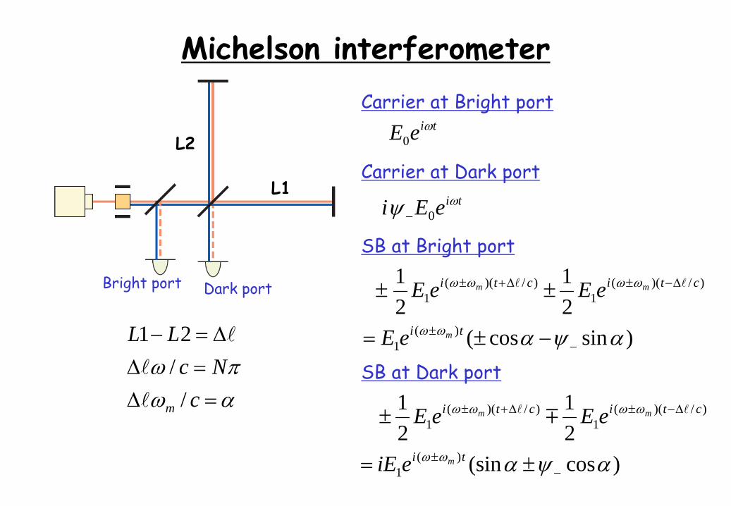
Michelson interferometer
Dark portBright port
L1
L2
cNc
LL
m //21
Carrier at Bright porttieE
0
Carrier at Dark porttieEi 0
SB at Bright port
)sincos(21
21
)(1
)/)((1
)/)((1
ti
cticti
m
mm
eE
eEeE
SB at Dark port
)cos(sin21
21
)(1
)/)((1
)/)((1
ti
cticti
m
mm
eiE
eEeE
Michelson interferometerCarrier at Bright port
tieE 0
Carrier at Dark porttieEi 0
SB at Bright port
)sincos(21
21
)(1
)/)((1
)/)((1
ti
cticti
m
mm
eE
eEeE
SB at Dark port
)cos(sin21
21
)(1
)/)((1
)/)((1
ti
cticti
m
mm
eiE
eEeE
cNc
LL
m //21
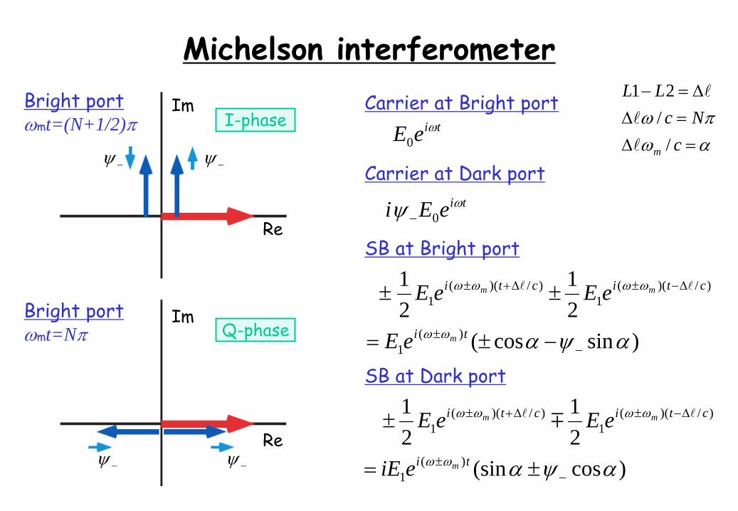
Bright portmt=(N+1/2)
Bright portmt=N
I-phase
Q-phase
Re
Im
Re
Im
Michelson interferometerCarrier at Bright port
tieE 0
Carrier at Dark porttieEi 0
SB at Bright port
)sincos(21
21
)(1
)/)((1
)/)((1
ti
cticti
m
mm
eE
eEeE
SB at Dark port
)cos(sin21
21
)(1
)/)((1
)/)((1
ti
cticti
m
mm
eiE
eEeE
cNc
LL
m //21
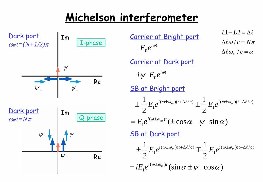
Dark portmt=(N+1/2)
Dark portmt=N
I-phase
Q-phase
Re
Im
Re
Im
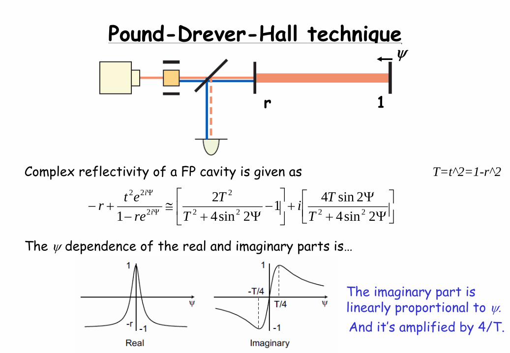
Pound-Drever-Hall technique
r 1
T=t^2=1-r^2Complex reflectivity of a FP cavity is given as
The dependence of the real and imaginary parts is…
The imaginary part is linearly proportional to And it’s amplified by 4/T.
2sin42sin41
2sin42
1 2222
2
2
22
TTi
TT
reetr i
i
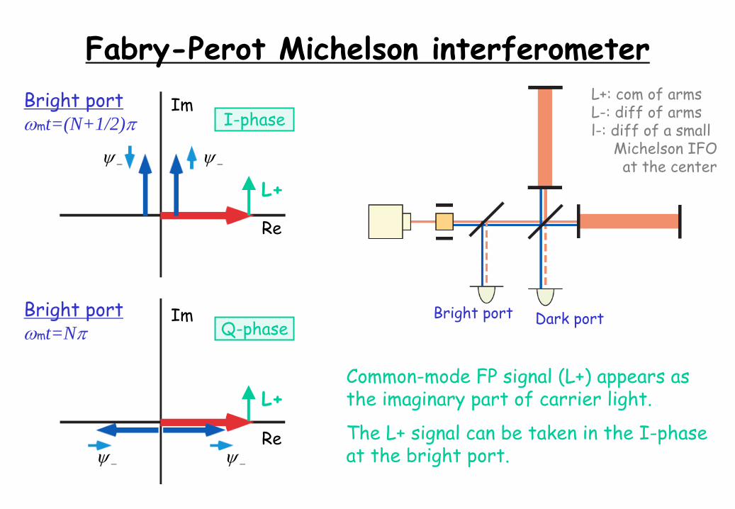
Fabry-Perot Michelson interferometerBright portmt=(N+1/2)
Bright portmt=N
I-phase
Q-phase
Re
Im
Re
Im
Dark portBright port
Common-mode FP signal (L+) appears asthe imaginary part of carrier light.
The L+ signal can be taken in the I-phaseat the bright port.
L+
L+
L+: com of armsL-: diff of armsl-: diff of a small
Michelson IFOat the center
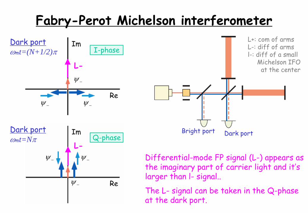
Fabry-Perot Michelson interferometerDark portmt=(N+1/2)
Dark portmt=N
I-phase
Q-phase
Re
Im
Re
Im
Dark portBright port
Differential-mode FP signal (L-) appears asthe imaginary part of carrier light and it’slarger than l-
signal..
The L-
signal can be taken in the Q-phaseat the dark port.
L-
L-
L+: com of armsL-: diff of armsl-: diff of a small
Michelson IFOat the center
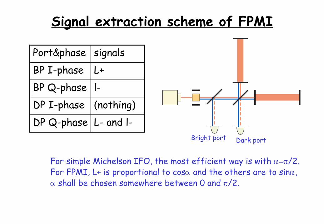
Signal extraction scheme of FPMI
Dark portBright port
Port&phase signalsBP I-phase L+BP Q-phase l-DP I-phase (nothing)DP Q-phase L-
and l-
For simple Michelson IFO, the most efficient way is with /2.For FPMI, L+ is proportional to cos
and the others are to sin,
shall be chosen somewhere between 0 and /2.
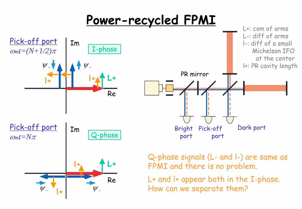
Power-recycled FPMIPick-off portmt=(N+1/2)
Pick-off portmt=N
I-phase
Q-phase
Re
Im
Re
Im
Dark portBright port
Q-phase signals (L-
and l-) are same asFPMI and there is no problem.L+ and l+ appear both in the I-phase.How can we separate them?
L+
L+
L+: com of armsL-: diff of armsl-: diff of a small
Michelson IFOat the center
l+: PR cavity length
Pick-off port
l+l+
l+
l+
PR mirror
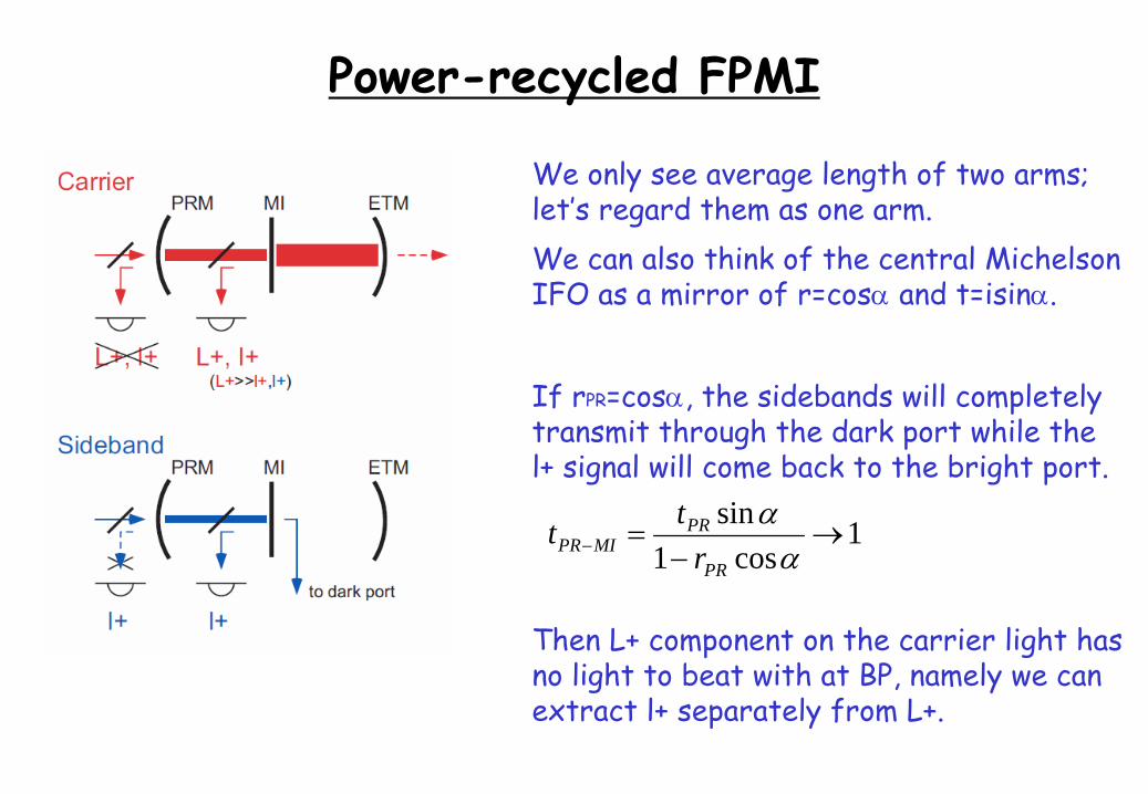
Power-recycled FPMI
We only see average length of two arms;let’s regard them as one arm.We can also think of the central MichelsonIFO as a mirror of r=cos
and t=isin.
If rPR
=cos, the sidebands will completelytransmit through the dark port while thel+ signal will come back to the bright port.
1cos1
sin
PR
PRMIPR r
tt
Then L+ component on the carrier light hasno light to beat with at BP, namely we canextract l+ separately from L+.
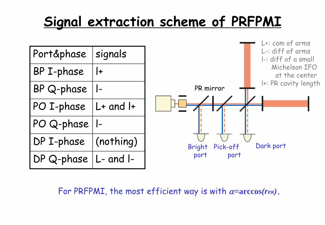
Signal extraction scheme of PRFPMI
Port&phase signalsBP I-phase l+BP Q-phase l-PO I-phase L+ and l+PO Q-phase l-DP I-phase (nothing)DP Q-phase L-
and l-
For PRFPMI, the most efficient way is with =arccos(rPR ).
Dark portBright port
L+: com of armsL-: diff of armsl-: diff of a small
Michelson IFOat the center
l+: PR cavity length
Pick-off port
PR mirror
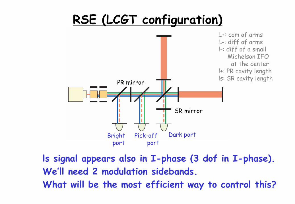
RSE (LCGT configuration)
Dark portBright port
L+: com of armsL-: diff of armsl-: diff of a small
Michelson IFOat the center
l+: PR cavity lengthls: SR cavity length
Pick-off port
PR mirror
SR mirror
ls
signal appears also in I-phase (3 dof
in I-phase).We’ll need 2 modulation sidebands.What will be the most efficient way to control this?
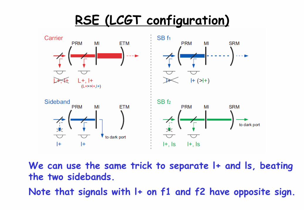
RSE (LCGT configuration)
We can use the same trick to separate l+ and ls, beating the two sidebands.Note that signals with l+ on f1 and f2 have opposite sign.
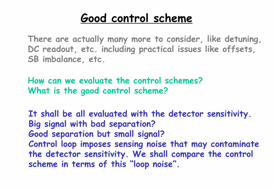
Good control scheme
There are actually many more to consider, like detuning,DC readout, etc. including practical issues like offsets,SB imbalance, etc.
How can we evaluate the control schemes?What is the good control scheme?
It shall be all evaluated with the detector sensitivity.Big signal with bad separation?Good separation but small signal?Control loop imposes sensing noise that may contaminatethe detector sensitivity. We shall compare the controlscheme in terms of this “loop noise”.
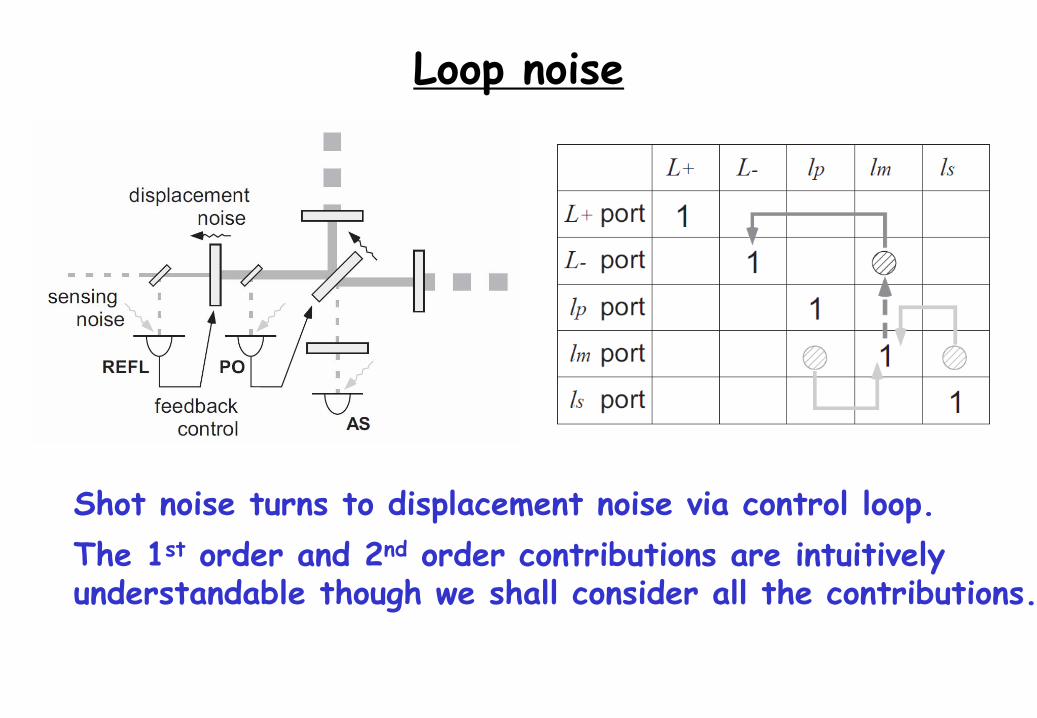
Loop noise
Shot noise turns to displacement noise via control loop.The 1st
order and 2nd
order contributions are intuitively
understandable though we shall consider all the contributions.
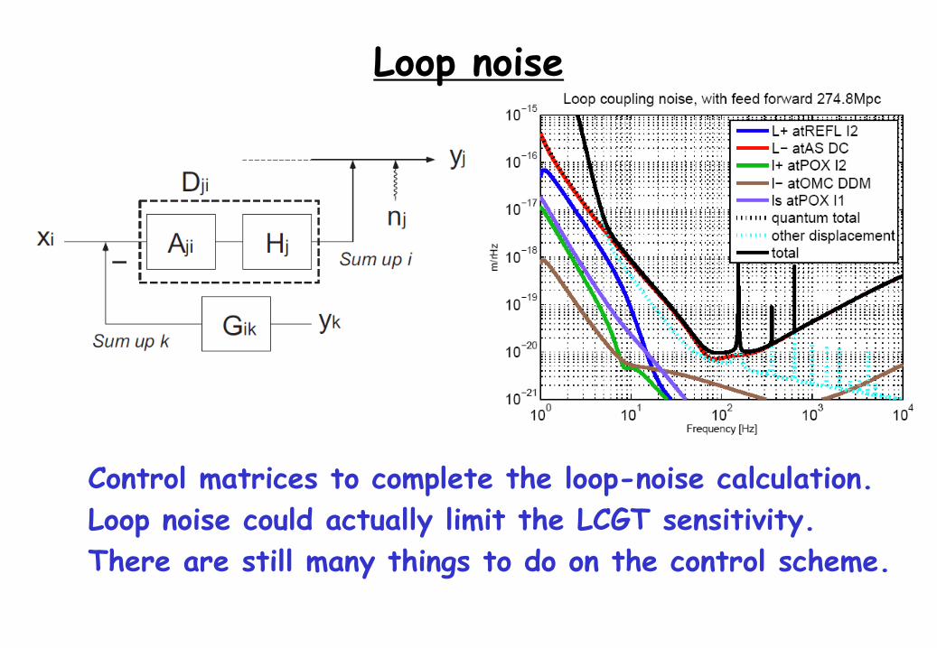
Loop noise
Control matrices to complete the loop-noise calculation.Loop noise could actually limit the LCGT sensitivity.There are still many things to do on the control scheme.