mge upsilon sts - brochure
TRANSCRIPT
>
> Simplifies installation and maintenance, while minimizing space requirements.
> Independent control boards and dualcooling systems and power suppliesensure high reliability performance.
> Text and mimic diagrams display modes of operation, system parameters and alarms.
> Allows isolation of a source formaintenance, without interrupting powerto the protected loads.
> Small footprint reduces required floorspace.
MGETM UpsilonTM STS
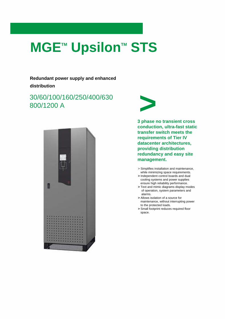
30/60/100/160/250/400/630800/1200 A
Redundant power supply and enhanced distribution
3 phase no transient cross conduction, ultra-fast static transfer switch meets the requirements of Tier IV datacenter architectures, providing distribution redundancy and easy site management.
MGETM UpsilonTM STS Features
High availability of energy : Compliant with data center TIA 942 and TIER IV requirements.MGE Upsilon™ STS supplies power to a range of equipment from two independent andredundant sources.Without disconnection, it transfers the supply from a preferred source to a alternate source, in either automatic or manual mode.
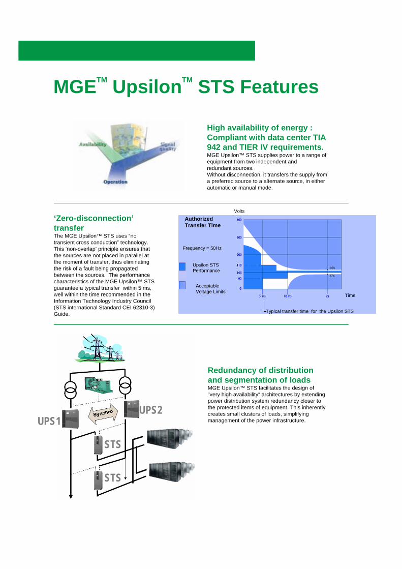
‘Zero-disconnection’transferThe MGE Upsilon™ STS uses “no transient cross conduction” technology. This ‘non-overlap’ principle ensures that the sources are not placed in parallel at the moment of transfer, thus eliminating the risk of a fault being propagated between the sources. The performancecharacteristics of the MGE Upsilon™ STS guarantee a typical transfer within 5 ms, well within the time recommended in the Information Technology Industry Council (STS international Standard CEI 62310-3) Guide.
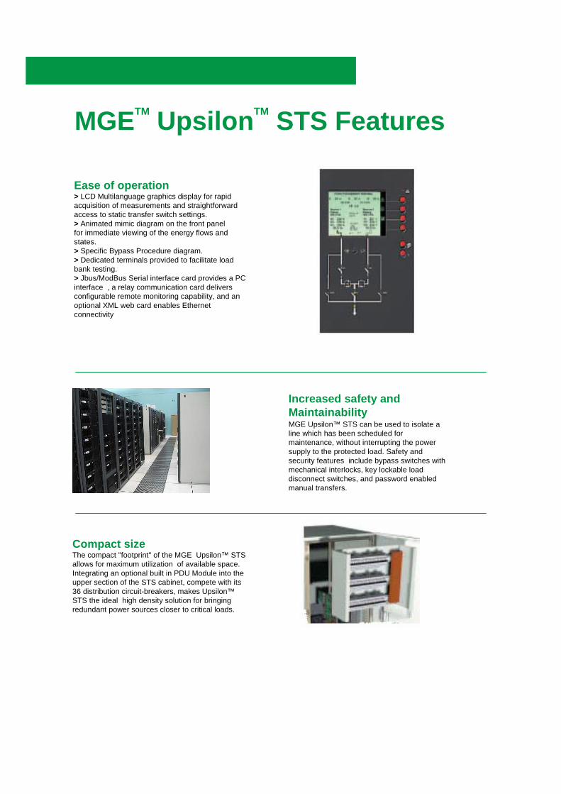
Redundancy of distribution and segmentation of loadsMGE Upsilon™ STS facilitates the design of "very high availability“ architectures by extending power distribution system redundancy closer to the protected items of equipment. This inherently creates small clusters of loads, simplifying management of the power infrastructure.
Time
Typical transfer time for the Upsilon STS
Authorized Transfer Time
Frequency = 50Hz
Upsilon STSPerformance
AcceptableVoltage Limits
Volts
STS
STS
UPS2UPS1
MGETM UpsilonTM STS Features
Increased safety andMaintainabilityMGE Upsilon™ STS can be used to isolate a line which has been scheduled for maintenance, without interrupting the power supply to the protected load. Safety and security features include bypass switches with mechanical interlocks, key lockable load disconnect switches, and password enabled manual transfers.
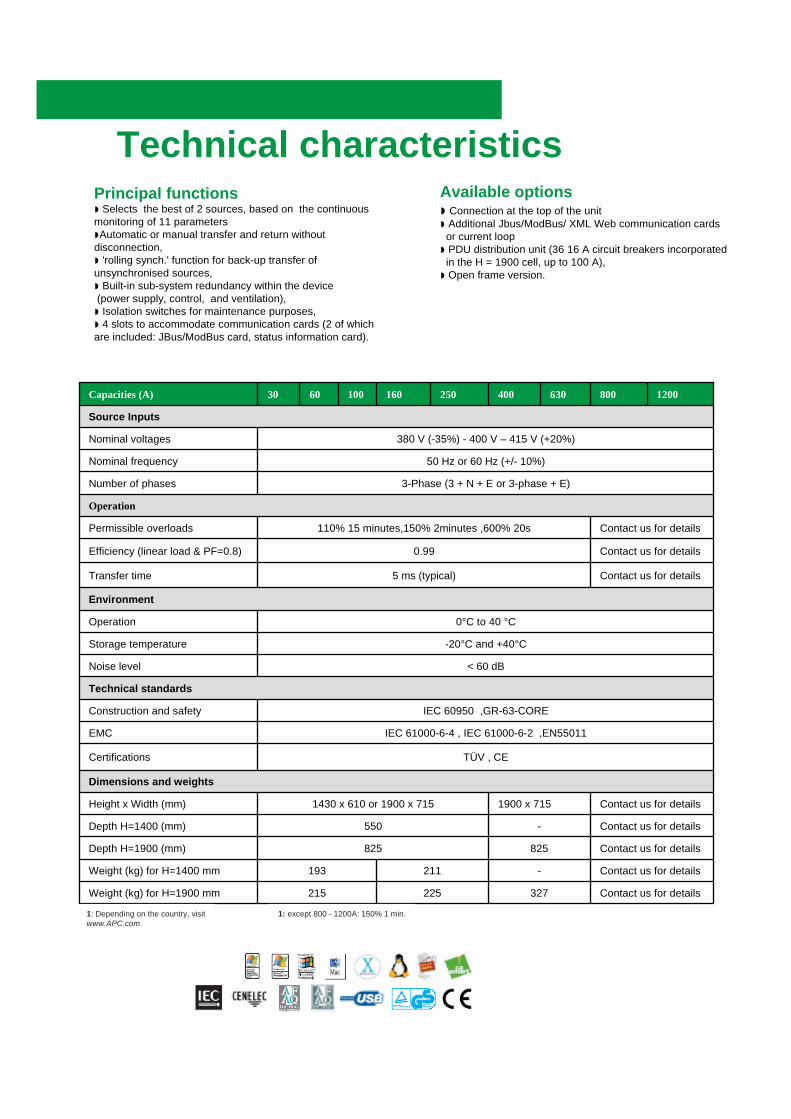
Ease of operation> LCD Multilanguage graphics display for rapid acquisition of measurements and straightforward access to static transfer switch settings.> Animated mimic diagram on the front panelfor immediate viewing of the energy flows and states.> Specific Bypass Procedure diagram.> Dedicated terminals provided to facilitate load bank testing.> Jbus/ModBus Serial interface card provides a PC interface , a relay communication card delivers configurable remote monitoring capability, and an optional XML web card enables Ethernet connectivity
Compact sizeThe compact "footprint" of the MGE Upsilon™ STS allows for maximum utilization of available space. Integrating an optional built in PDU Module into the upper section of the STS cabinet, compete with its 36 distribution circuit-breakers, makes Upsilon™STS the ideal high density solution for bringing redundant power sources closer to critical loads.
Dimensions and weights
TÜV , CECertifications
IEC 61000-6-4 , IEC 61000-6-2 ,EN55011EMC
IEC 60950 ,GR-63-COREConstruction and safety
380 V (-35%) - 400 V – 415 V (+20%)Nominal voltages
50 Hz or 60 Hz (+/- 10%)Nominal frequency
3-Phase (3 + N + E or 3-phase + E)Number of phases
Operation
Contact us for details110% 15 minutes,150% 2minutes ,600% 20sPermissible overloads
Contact us for details0.99Efficiency (linear load & PF=0.8)
Contact us for details5 ms (typical) Transfer time
Environment
0°C to 40 °COperation
-20°C and +40°CStorage temperature
< 60 dBNoise level
Technical standards
Contact us for details1900 x 7151430 x 610 or 1900 x 715Height x Width (mm)
Contact us for details-550Depth H=1400 (mm)
Contact us for details825825Depth H=1900 (mm)
Contact us for details-211193Weight (kg) for H=1400 mm
Contact us for details327225215Weight (kg) for H=1900 mm
Source Inputs
12008006304002501601006030Capacities (A)
1: Depending on the country, visitwww.APC.com.
1: except 800 - 1200A: 150% 1 min.
Technical characteristicsAvailable options◗ Connection at the top of the unit◗ Additional Jbus/ModBus/ XML Web communication cards
or current loop ◗ PDU distribution unit (36 16 A circuit breakers incorporated
in the H = 1900 cell, up to 100 A),◗ Open frame version.
Principal functions◗ Selects the best of 2 sources, based on the continuous monitoring of 11 parameters◗Automatic or manual transfer and return without disconnection,◗ 'rolling synch.' function for back-up transfer of unsynchronised sources,◗ Built-in sub-system redundancy within the device(power supply, control, and ventilation),◗ Isolation switches for maintenance purposes,◗ 4 slots to accommodate communication cards (2 of which are included: JBus/ModBus card, status information card).