mew · 2014-09-27 · ad-alg 726 air propagation force weapons of a relativistic lab kirtland...
TRANSCRIPT

AD-ALG 726 AIR FORCE WEAPONS LAB KIRTLAND AFB NM FIG 20/8PROPAGATION OF A RELATIVISTIC CHARGED PARTICLE BEAM THROUGH AN --ETCIU)
MAY 80 R W LEMKE. K A DREYERUNCLASSIFIED AFWL-TR-79- 198 L
MEW

4% 111 . Q 11_2.2
an*4 111120
11111 1.5111L
* MiCROCOPY iuSOwLO1O TESI CHARI

- U.
AFWL-TR-79-1 98 E ,<AFWL-TR-
79-1 98LEVL$PROPAGATION OF A RELATIVISTIC CHARGEDPARTICLE BEAM THROUGH AN AIR MEDIUMWITH CONDUCTING BOUNDARIES
00) R. W. LemkeK. A. Dreyer
DTIC, ELECTE,
May 1980 DEC 18 19814d' 5 Final Report
Approved for public release; distribution unlimited.
I
AIR FORCE WEAPONS LABORATORY
Air Force Systems CommandK Kirtland Air Force Base, NM 87117
81 18 027~~L ' - --------

AFWL-TR-79-198
The final report was prepared by the Air Force Weapons Laboratory, KirtlandAir Force Base, New Mexico, under Job Order 57972202. Mr R. W. Lemke (NTYP) wasthe Laboratory Project Officer-in-Charge.
When US Government drawings, specifications, or other data are used for anypurpose other than a definitely related Government procurement operation, theGcvernment thereby incurs no responsibility nor any obligation whatsoever, andthe fact that the Government may have formulated, furnished or in any waysupplied the said drawings, specifications, or other data, is not to be regardedby implication or otherwise, as in any manner licensing the holder or any otherperson or corporation, or conveying any rights or permission to manufacture, use,or sell any patented invention that may in any way be related thereto.
This report has been authored by an employee of the United States Government.The United States Government retains a nonexclusive, royalty-free license to pub-lish or reproduce the material contained herein, or allow others to do so, forthe United States Government purposes.
This report has been reviewed by the Public Affairs Office and is releasableto the National Technical Information Service (NTIS). At NTIS, it will be avail-able to the general public, including foreign nations.
This technical report has been reviewed and is approved for publication.
RYON W EKEProject Officer
FOR THE DIRECTOR
NORMAN F. RODERICK THOMAS W. CIAMBRONE|Lt Col, USAF Colonel, USAFChief, Advanced Concepts Branch Chief, Applied Physics Divisior.
DO NOT RETURN THIS COPY. RETAIN OR DESTROY.

U;CT A TWT fl
SECURITY CLASSIFICATION OF TNIS PAGE (When DOt Entered)"' .... .READ INSTRUCTIONS
REPORT DOCUMENTATION PAGE BEFORE COMPLETING FORMI REPORT NUM ER 2. GOVT ACCESSION NO. I RECIPIENT'S CATALOG NUMBER
AMW-TR-79-198ADIAA 9Q t4. TIT.E ( nd Subtitle) S TYPE OF REPORT 6 PERIOD Cove [o
PROPAGATION OF A RELATIVISTIC CHARGED PARTICLE Final ReportBEAM THROUGH AN AIR MEDIUM WITH CONDUCTINGBOUNDARIES 6 PERPORMING OR*. REPORT NuMER
7 AUTOR(I) S. CONTRACT ON GRANT NUMUE0es)
R. W. LemkeK. A. Dreyer
9 PERFORIMING ORGANIZATION N4AME ANO ADDRESS 10 PROGRAM ELEMEN. PROJECT, TASK
Air Force Weapons Laboratory (NTYP) AREA A WR UNT NUMERS
Kirtland Air Force Base, NM 87117 62601F/57972202
I1 CONTROLLING OFFICE NAME ANO ADDRESS Qi. REPORT DATE
Air Force Weapons Laboratory (NTYP) May 1980Kirtland Air Force Base, NM 87117 13 NUMIERO WAGES
14I MONITORING AGENCY NAME & A0oRESS(01 dif!erent Irm Control ing Office) IS. SECURITY CLASS. rot htS report,
UNCLASSIFIED
IS. DECLASSIVICATION OOP40RADING, SCMEDU1.9
IS. OISTfRISJTION STATEMENT (of this Report)
Approved for public release; distribution unlimited.
17. OISTRU8UTION STA TEMENT (of thO abetrect entered in Stock 20. it different from Report)
I8 SUPPLEMENTARY NOTES
It. KEY WORDS (Continue en rtvore side it neeeery end Identify by block number)
Electron Beam
Particle Beam
I20 'ABSTRACT (ContInue an POefefl stde If fle*0#9OP eng identify by block Mnnbe)
Many propagation experiments involve firing a relativistic charged particlebeam into a column of air bounded by the conducting walls of a drift tube.In this investigation, the extent to which the magnitude of the resultingreturn current and, hence, the stability of the propagating beam is affectedby the presence of conducting boundaries. Maxwell's equations are employedto derive the appropriate wave equation. This equation is transformed intoa diffusion equation which is numerically solved for various boundary param-eters.
DD 1 JAN1473 UNCLASSIFIED
SECURITY CLASSIFICATION OF FN-IS PAGE fhen Date eIpnee;
S- .- __________

AFWL-TR-79-198
CONTENTS
INTRODUCTI ON 3
ASSUMPTIONS AND EQUATIONS 4
BEAM PROFILE AND PLASMA CONDUCTIVITY 8
NUMERICAL ALGORITHM 10
RESULTS AND CONCLUSIONS 12
Aooession For
MjIS GFRA&IDTIC TABUnannounced [JJustificatio
By B_.
Distribution/
Availability Codes
IAvail and/or
Distj Special
1/2
k6

AFWL-TR- 79-198
INTRODUCTION
Some applications of relativistic electron beams (REB) necessitate that
they stably propagate some distance through air. Whether the beam will propagate
or not depends on the pressure of the air into which it is fired. The goal of
many REB experiments is to determine the pressure most conducive to beam
propagation.
Low pressure environments, into which an REB may be fired, can be created
by various means. The most practical means, experimentally, is to use a drift
tube whose interior pressure is adjustable. The beam is then fired into the
tube and monitored as it passes various points along the length of the chamber.
The drift tubes used in propagation experiments generally have cylindrical
symmetry, and are sometimes made of highly conductive metals. Hence, because of
the conducting boundary, firing an REB into a metallic drift tube may not be the
same as firing it into the unbounded atmosphere.
In this investigation, we endeavor to determine (by solving Maxwell's
equations with appropriate boundary conditions) a minimum drift tube diameter
such that conducting boundaries have a negligible affect on relativistic electron
beam-plasma interactions.

AFWL-TR-79-198
ASSUMPTIONS AND EQUATIONS
As is well known, Maxwell's equations, in Gaussian units, for material media
are:
V • E - 4wP (1)
'B 0 (2)
VxB= -E- (3)
S c C at (4)
To obtain the appropriate wave equation, apply the Vx operator to equation 3
and employ the identity
VxVxF V(V. -V2 "
to get
2 - V .EB (5)
Substituting into equation 5, the expressions for V • E and V x B yields
7 2 - 1 a~ 4Tal 6c2 at2 c at (6)
To investigate the problem, we need solve only the z component of equation 6.
To do so, we make the assumption of cylindrical symmetry. That is, we assume
that E., Br, and B are zero, and that the remaining components of E and B are
independent of the azimuthal coordinate 0. In addition, we assume that Ohm's law,
J = aE, is valid in the plasma. With the above assumptions, the z component of
equation 6 becomes
Ia a a2 41r a 1 a2E -z +T- z --2 a z "N t z T C
"4 + 2 + J zOo
where J' represents the REB current density.z
4

AFWL-TR-79-198
We simplify equation 7 via the transformation
= t -z (8a)c
Z- z (8b)
Now
- -- a (9a)
and
3 _ a 13(9b)az TZ - c (b
We now make the so-called frozen beam approximation; i.e., we assume that the
fields translate rigidly with the beam. For any given field component F, the
frozen beam approximation is equivalent to the mathematical statement
DF 3F FDt +v 0 (10)
or
aF _ F~-3t - (11)
where v is the velocity of the beam electrons. The energy of the beam electrons
is generally greater than 1 MeV. Hence. we can further assume that v - c. Thus,
aE aEa ---- (12)
Substitution of the operator identities 9a and 9b into equation 12 yields
Z Z Z (13)
Equation 13 is valid only if
aEz _ 0 (14)
That is, with respect to the coordinates Z and T, the frozen beam approximation
is equivalent to
aE
3z z " (15
. .. . . .... . . .. ... .( -' -

AFWL-TR-79-198
In view of equation 15, the identities 9a and 9b become
a .- a (16a)at aT
and
(16b)
In terms of the new coordinates, equation 7 can be written as
13 _ 4nr 3 4_r 3 4w (J1
r -r -g- Ez c 2 -T a Ez c T c 2 (17)
An REB propagating through air generates a plasma, resulting in space charge
neutralization (SCN). We account for SCN by letting
3'•P -= _C exp (- 4"n'oT) (18)
Substituting equation 18 into 17 yields
13 3 4T a 47T ar.E - E (19)r r r - z c cz c23
where
3'* - J' El - exp (-4vaT)J (20)z z
We assume that the conductivity of the drift tube is large enough to be con-
sidered infinite. Continuity of E across the plasma-wall interface requires2Ithat
Ez (R T) -0 (21)
where R represents the inner radius of the drift tube.w
Since the beam electrons are highly relativistic, Ez is approximately zero
at the head of the pulse. That is,
E (r,o) 0 (22)z
6
/ =

AFWL-TR-79-198
The 9 component of equation 3, in the new coordinates, is
-E (r,T) -B (r,T) (23)Dr z c at BEvaluating equation 23 at r - 0 yields
a E (r,T) I - 0 (24)r' O
Equations 19, 21, 22 and 24 uniquely determine E (r,T) inside the driftz
tube chamber.
7'

AFWL-TR-79-198
BEAM PROFILE AND PLASMA CONDUCTIVITY
The beam J' is assumed to have the following profile:z
J (T/T1 )/(l + r2/a2)2 T < 1 (25a)
z Jo /(1 + r2/a2)2 T< T < T (25b)
z b
0T > T (25c)
where and a represent the on-axis beam current density and Bennet radius,b
respectively. Also,
0 0Oia0 b I/Ta (26)
where 1 0 is the on axis beam current.b
We assume that the plasma conductivity (a) is generated with a radial profile
similar to that of the beam. That is, we let
a = T0/(l + r2/a2)2 (27)
where a0 is the on-axis conductivity. We employed existing air chemistry models
(Ref. l)* to numerically obtain the on-axis conductivity. Figure 1 is a graph of
on-axis conductivity versus distance (in seconds) back into the pulse. The beam
parameters used are indicated at the lower right-hand corner of the graph. The
rise length of the pulse is AL(= TIc) and its length is L(- Tzc).
1 Dreyer. ' A., EZectric and Magnetic Fielde of An Intense PuZse of ReZativistic:ect 6e Propagating Through Air, AFIT/DS/PH/79-1, AFIT, Wright-Patterson AFB-.,Lo, 1979.
• Johnston, R., private communication.
8

AFWL-TR-79-198
P 760. OT
lo1l
T, =1. 5MOV
a:- 2. ocm
L LSOVc(20ns)
108 L z4125cm(137.5ns)
Figure 1. On-Axis conductivity versus distance.
9
L1
AFWL-TR-79-198
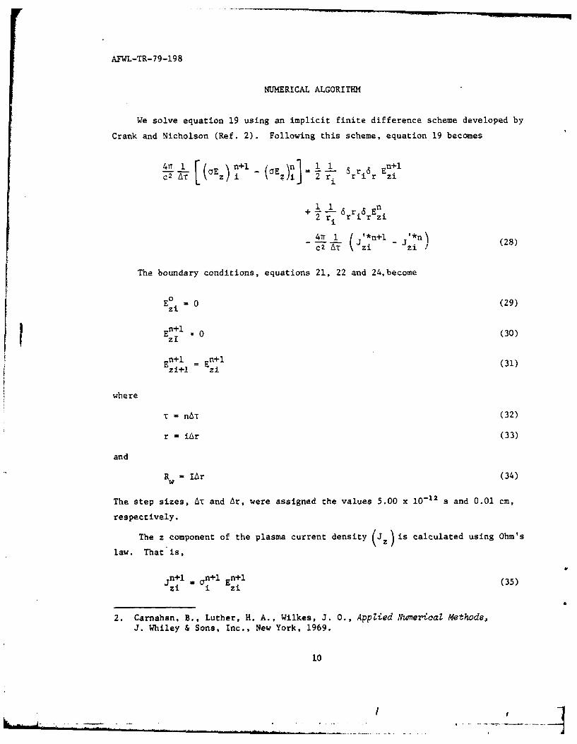
NUMERICAL ALGORITHM
We solve equation 19 using an implicit finite difference scheme developed by
Crank and Nicholson (Ref. 2). Following this scheme, equation 19 becomes
47r 1 ri ) n+l n 11Ez n+lC a Ez )i 2 r i ri 6r zi
1 1 nrir~
+ 6 r 6 En2 ri r ir zi
47 1 ( jz*n+l - n' (28)c2 AT 1 2i i
The boundary conditions, equations 21, 22 and 24,become
E 0 0 (29)
zlE n al (30)IZEn+1 = n+l (31)zi+l zi
where
T - nAt (32)
r - iAr (33)
and
R - IAr (34)W
The step sizes, AT and Ar, were assigned the values 5.00 x 10 - 1 2 s and 0.01 cm,
respectively.
The z component of the plasma current density Jz is calculated using Ohm's
law. That is,
jn+l _n+l En+l (35)zi i zi
2. Carnahan, B., Luther, H. A., Wilkes, J. 0., Applied Numerical Methods,J. Whiley & Sons, Inc., New York, 1969.
10

AFWL-TR-79-198
We integrate equation 35, using Simpson's rule, to obtain the plasma current
(p) at each time step. The numerical expression for I is
SJn+l Jn+lIn~l 2 rJn1l+ 4r1 J + 2r2p 3 ozo Z1 z2
+ 2nr j i+l + 4r n+l n+131-3 JZ-3 r1 2 Jz- 2 + r -J- 1 )
where I w R /r.
i1
/,

AFWL-TR-79-198
RESULTS AND CONCLUSIONS
The results of our computer runs are summarized in Table I and Figure 2.
The beam parameters, with which equation 28 was solved, are given in the lower
right-hand corner of this figure. The plasma currents in this table and figure
were evaluated at the top of the current rise (T-T,) for three different pressures,
given in units of Torr.
TABLE 1. RESULTS OF COMPUTER RUNS
P-760T P-76T P-7.6T
3.0 3.3 3.8 8.5
5.0 6.5 7.1 14.0
8.0 9.5 10.0 17.9
10.0 10.7 11.2 19.3
12.0 11.7 12.1 20.3
15.0 12.7 13.0 21.3
20.0 13.9 14.1 22.3
35.0 15.7 15.9 23.8
50.0 16.7 16.8 24.5
The curves in Figure 2 indicate that, at each pressure, the plasma current
increases significantly out to Rw - 20.0 cm. Thereafter, out to Rw - 50.0 cm,
the plasma current increases only a few percentage points. That is, the conducting
boundaries significantly influence the plasma current when the drift tube radius
is less than 10 Bennet radii. Thus, for a beam with a 2 cm Bennet radius, the
minimum drift tube radius beyond which wall effects are insignificant is 10
Bennet radii.
On the basis of our results, it is suggested that regardless of beam size
wall affects are negligible when the ratio of drift tube radius to Bennet radius
is at least 10. That is, drift tube propagation experiments may simulate propaga-
tion of beams through the air, provided that the ratio of beam radius to drift
tube radius is greater than 10.
12
F I i

AFWL-TR-79-198
32.5
30.0
27.5
25.0 -P a7.6T
22.5 -
20.0
17.5
-15.0
12.5 0
10.0
7.5 Ibz i M30A
T* =1. 5MOV
5.0a =2.cm
& L 00cm(2Ons)
L v 4125cm(137.5ns)2.5
0.I I I I5.0 10.0 15.0 20.0 25.0 30.0 35.0 40.0 45.0 50.0
Rw(CN)
Figure 2. Results of computer runs.
13/14
I/