metal injection moulding: a near net shape fabrication ... · pdf filefor the manufacture of...
TRANSCRIPT
RTO-MP-AVT-139 8 - 1
UNCLASSIFIED/UNLIMITED
UNCLASSIFIED/UNLIMITED
Metal Injection Moulding: A Near Net Shape Fabrication Method for the Manufacture of Turbine Engine Component
Benoit Julien Maetta Sciences
75 bvd. Mortagne, suite 109 Boucherville, Quebec J4B 6Y4
CANADA
Mélissa Després Pratt & Whitney Canada Corp.
1000, Bvd. Marie-Victorin Longueuil, Quebec J4G 1A1
CANADA
ABSTRACT Metal Injection Moulding (MIM) is an attractive technology for the net shape fabrication of small complex shape parts made of exotic materials such as stainless steels, nickel alloys, titanium alloys and ceramics. A novel process based on Low Pressure Injection Moulding (LPIM), has been developed in order to render the process more economically feasible for typically smaller batch sizes found in aeronautic applications. In this work, results on the processing and characterization of Inconel 625 LPIM material are presented. In depth microstructural characterization was performed on the starting powder and on thermally debound samples in order to properly understand the debinding process in relation with phases present in the microstructure of debound and sintered parts. Results indicate that a Nb and Mo rich phase found in the starting powder led to the formation of second phase particles such as M23C6, M6C and MC carbides as well as Laves phase in the debound and sintered samples. The sintering process indicated that the dissolution of second phase particles in the microstructure can be achieved and needs to be optimized with secondary heat treatment such as solution annealing.
1 INTRODUCTION Nickel superalloys such as Inconel 625 were developed to withstand the intense conditions present in gas turbine engines while preserving relatively high mechanical properties. High performance metallic components made of this alloy can be fabricated using a wide variety of industrial processes and are typically found in the combustion chamber, fuel injection system and gas generator assemblies. Until now, costly manufacturing processes such as machining, investment casting, and hot isostatic pressing have been used for the fabrication of small complex shape parts. Recent material shortages and increases in raw material costs have justified the development of a novel processing route for the fabrication of aeronautic parts. A low-pressure injection moulding process, LPIM, has been developed for the fabrication of parts made of Inconel 625, which maximizes material utilization and avoids the poor machinability and formability, which is typically encountered with the use of conventional forming processes. LPIM is now considered for the production of high performance structural components requiring strength close to that of wrought materials. A major advantage of using this technology resides in the ability to fabricate net shape or near net shape small complex parts. Furthermore, LPIM overcomes the shape limitations of the more traditional powder metallurgy axial pressing process.
Julien, B.; Després, M. (2006) Metal Injection Moulding: A Near Net Shape Fabrication Method for the Manufacture of Turbine Engine Component. In Cost Effective Manufacture via Net-Shape Processing (pp. 8-1 – 8-16). Meeting Proceedings RTO-MP-AVT-139, Paper 8. Neuilly-sur-Seine, France: RTO. Available from: http://www.rto.nato.int/abstracts.asp.
Click here to view PowerPoint presentation; Press Esc to exit
Report Documentation Page Form ApprovedOMB No. 0704-0188
Public reporting burden for the collection of information is estimated to average 1 hour per response, including the time for reviewing instructions, searching existing data sources, gathering andmaintaining the data needed, and completing and reviewing the collection of information. Send comments regarding this burden estimate or any other aspect of this collection of information,including suggestions for reducing this burden, to Washington Headquarters Services, Directorate for Information Operations and Reports, 1215 Jefferson Davis Highway, Suite 1204, ArlingtonVA 22202-4302. Respondents should be aware that notwithstanding any other provision of law, no person shall be subject to a penalty for failing to comply with a collection of information if itdoes not display a currently valid OMB control number.
1. REPORT DATE MAY 2006
2. REPORT TYPE N/A
3. DATES COVERED -
4. TITLE AND SUBTITLE Metal Injection Moulding: A Near Net Shape Fabrication Method for theManufacture of Turbine Engine Component
5a. CONTRACT NUMBER
5b. GRANT NUMBER
5c. PROGRAM ELEMENT NUMBER
6. AUTHOR(S) 5d. PROJECT NUMBER
5e. TASK NUMBER
5f. WORK UNIT NUMBER
7. PERFORMING ORGANIZATION NAME(S) AND ADDRESS(ES) Maetta Sciences 75 bvd. Mortagne, suite 109 Boucherville, Quebec J4B6Y4 CANADA
8. PERFORMING ORGANIZATIONREPORT NUMBER
9. SPONSORING/MONITORING AGENCY NAME(S) AND ADDRESS(ES) 10. SPONSOR/MONITOR’S ACRONYM(S)
11. SPONSOR/MONITOR’S REPORT NUMBER(S)
12. DISTRIBUTION/AVAILABILITY STATEMENT Approved for public release, distribution unlimited
13. SUPPLEMENTARY NOTES See also ADM202748. Cost Effective Manufacture via Net Shape Processing (Rentabilite de fabrication parun traitement de finition immediate), The original document contains color images.
14. ABSTRACT
15. SUBJECT TERMS
16. SECURITY CLASSIFICATION OF: 17. LIMITATION OF ABSTRACT
SAR
18. NUMBEROF PAGES
38
19a. NAME OFRESPONSIBLE PERSON
a. REPORT unclassified
b. ABSTRACT unclassified
c. THIS PAGE unclassified
Standard Form 298 (Rev. 8-98) Prescribed by ANSI Std Z39-18
Metal Injection Moulding: A Near Net Shape Fabrication Method for the Manufacture of Turbine Engine Component
8 - 2 RTO-MP-AVT-139
UNCLASSIFIED/UNLIMITED
UNCLASSIFIED/UNLIMITED
Powder Injection moulding is typically carried out with high pressure injection presses and requires complex and expensive automated tooling made of hardened steel to resist the high injection pressures and wear from the metallic particles in the feedstock. Although advantageous for high productivity, this processing route is not quite suited for the typical smaller batch size of the aeronautic industry. Adaptation of the traditional MIM process helped maintain its attractive characteristics even for smaller batches (5000-10000 parts). Technologies such as rapid manufacturing for mould fabrication and the use of an Inconel 625 LPIM feedstock have been successfully applied on test specimens and are now considered for applications in gas turbine engines. Manual intervention for the moulding operation in the prototyping phase is preferred rather than the use of complex and costly automated tooling. This work focuses only on microstructural characterisation of Inconel 625 produced by the novel LPIM technique. This approach is taken in order to thoroughly understand the material’s microstructure before reaching specimen fabrication for material characterization and design curve. The aim is to minimise the presence of detrimental phases such as carbides and Laves phases [1,2] that may affect service performances of components before part specific development. Good quality specimens were moulded using an injection pressure below 50 Psi. A thermal debinding treatment was developed to properly extract the binder components and avoid carbon contamination of the finished part. The sintering treatment was engineered to produce a microstructure with small grain size and a final density greater than 95% theoretical.
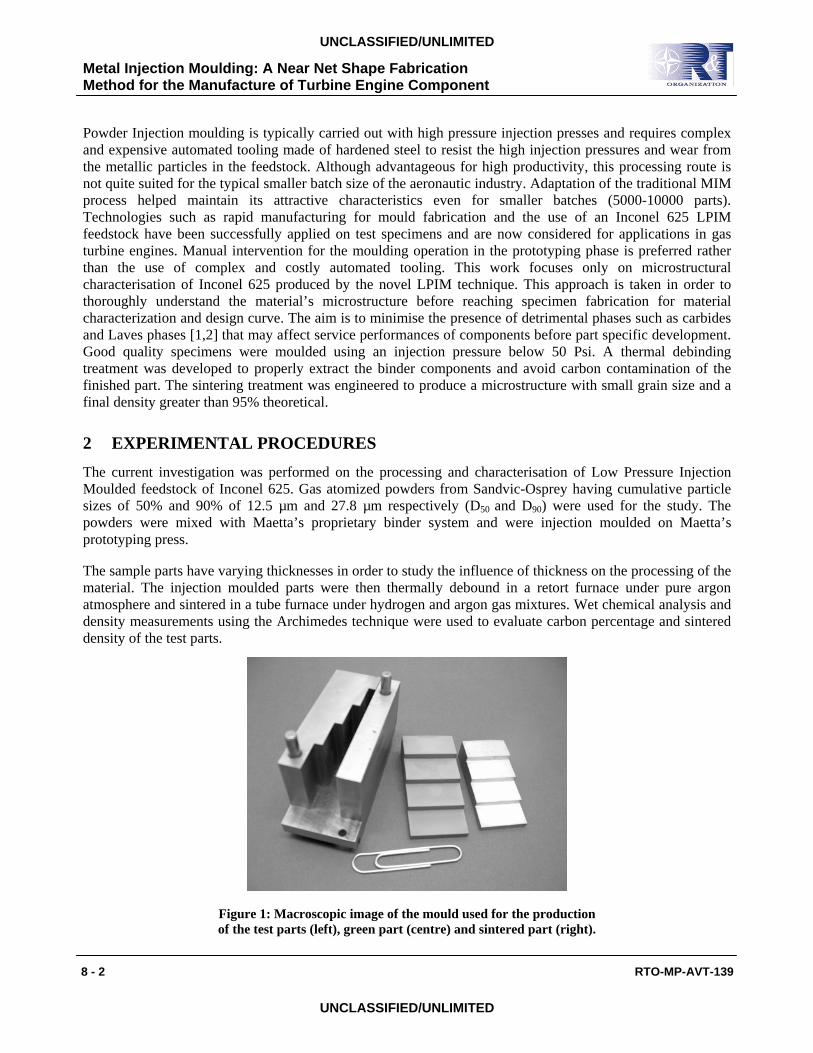
2 EXPERIMENTAL PROCEDURES The current investigation was performed on the processing and characterisation of Low Pressure Injection Moulded feedstock of Inconel 625. Gas atomized powders from Sandvic-Osprey having cumulative particle sizes of 50% and 90% of 12.5 µm and 27.8 µm respectively (D50 and D90) were used for the study. The powders were mixed with Maetta’s proprietary binder system and were injection moulded on Maetta’s prototyping press.
The sample parts have varying thicknesses in order to study the influence of thickness on the processing of the material. The injection moulded parts were then thermally debound in a retort furnace under pure argon atmosphere and sintered in a tube furnace under hydrogen and argon gas mixtures. Wet chemical analysis and density measurements using the Archimedes technique were used to evaluate carbon percentage and sintered density of the test parts.
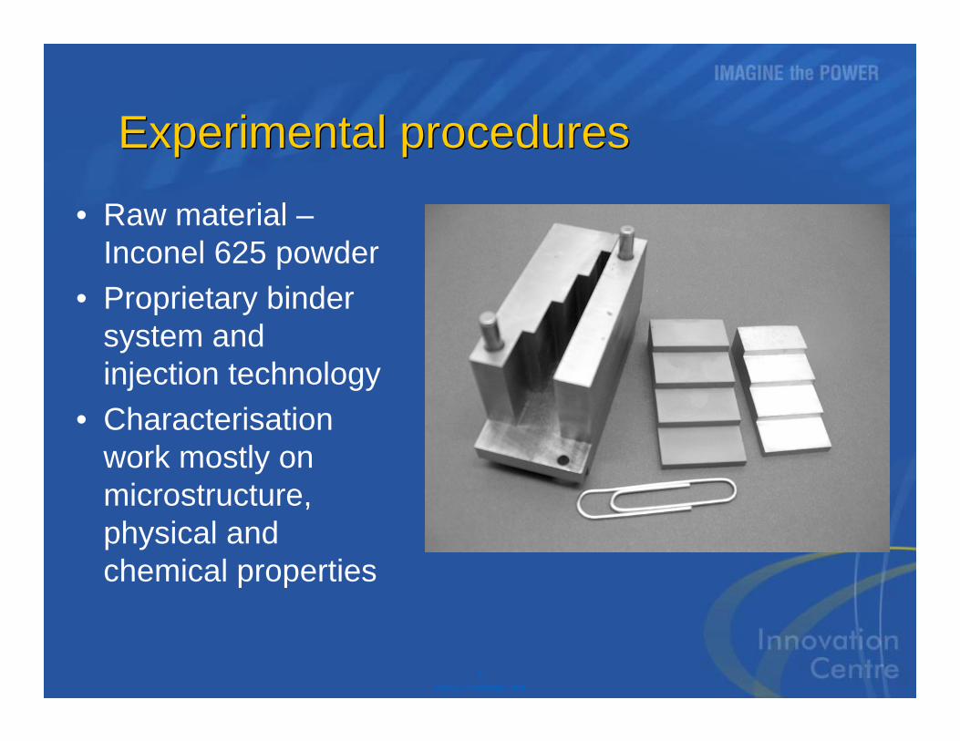
Figure 1: Macroscopic image of the mould used for the production of the test parts (left), green part (centre) and sintered part (right).
Metal Injection Moulding: A Near Net Shape Fabrication Method for the Manufacture of Turbine Engine Component
RTO-MP-AVT-139 8 - 3
UNCLASSIFIED/UNLIMITED
UNCLASSIFIED/UNLIMITED
Microstructural characterisation using optical microscopy was performed on all thicknesses of the test parts, in the debound and sintered conditions. Sample preparation was performed in the usual way. Scanning Electron Microscope (SEM) analyses were performed on a JEOL JSM840 microscope equipped with an Oxford EDS spectrometer. Transmission Electron Microscope (TEM) investigation was performed on selected test parts in the debound and sintered state as well as the starting powder. The TEM is a JEOL JEM-2100F equipped with an Oxford Energy Dispersive Spectrometer (EDS). The sample preparation for the TEM analyses was performed on a Focalised Ion Beam (FIB) model FB-2000A by Hitachi.
3 RESULTS
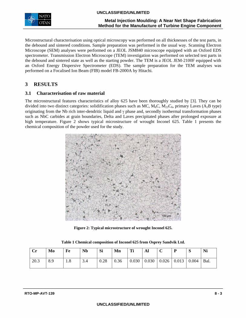
3.1 Characterisation of raw material The microstructural features characteristics of alloy 625 have been thoroughly studied by [3]. They can be divided into two distinct categories: solidification phases such as MC, M6C, M23C6, primary Laves (A2B type) originating from the Nb rich inter-dendritic liquid and γ phase and, secondly isothermal transformation phases such as NbC carbides at grain boundaries, Delta and Laves precipitated phases after prolonged exposure at high temperature. Figure 2 shows typical microstructure of wrought Inconel 625. Table 1 presents the chemical composition of the powder used for the study.
Figure 2: Typical microstructure of wrought Inconel 625.
Table 1 Chemical composition of Inconel 625 from Osprey Sandvik Ltd.
Cr Mo Fe Nb Si Mn Ti Al C P S Ni
20.3 8.9 1.8 3.4 0.28 0.36 0.030 0.030 0.026 0.013 0.004 Bal.
Metal Injection Moulding: A Near Net Shape Fabrication Method for the Manufacture of Turbine Engine Component
8 - 4 RTO-MP-AVT-139
UNCLASSIFIED/UNLIMITED
UNCLASSIFIED/UNLIMITED
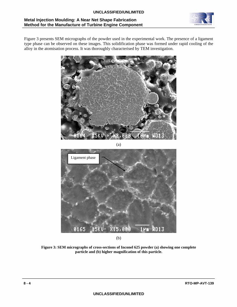
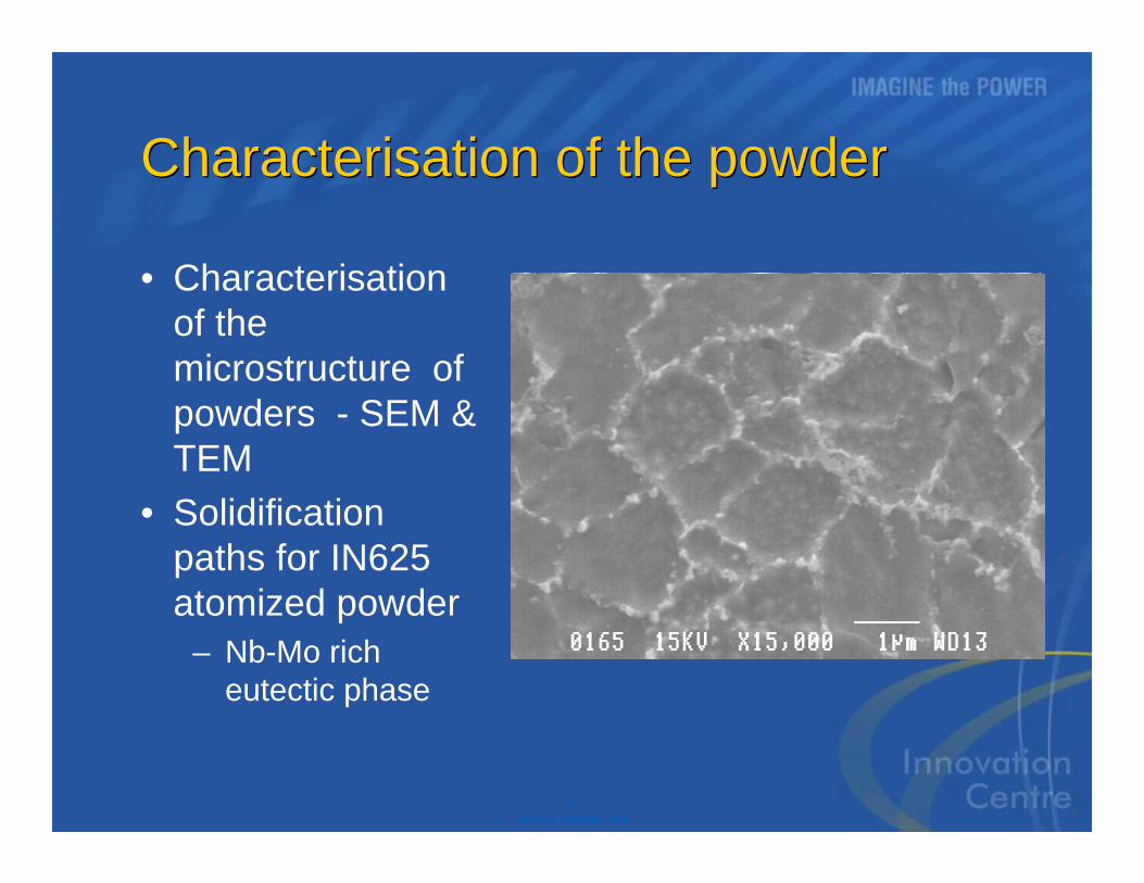
Figure 3 presents SEM micrographs of the powder used in the experimental work. The presence of a ligament type phase can be observed on these images. This solidification phase was formed under rapid cooling of the alloy in the atomisation process. It was thoroughly characterised by TEM investigation.
(a)
(b)
Figure 3: SEM micrographs of cross-sections of Inconel 625 powder (a) showing one complete particle and (b) higher magnification of this particle.
Ligament phase
Metal Injection Moulding: A Near Net Shape Fabrication Method for the Manufacture of Turbine Engine Component
RTO-MP-AVT-139 8 - 5
UNCLASSIFIED/UNLIMITED
UNCLASSIFIED/UNLIMITED
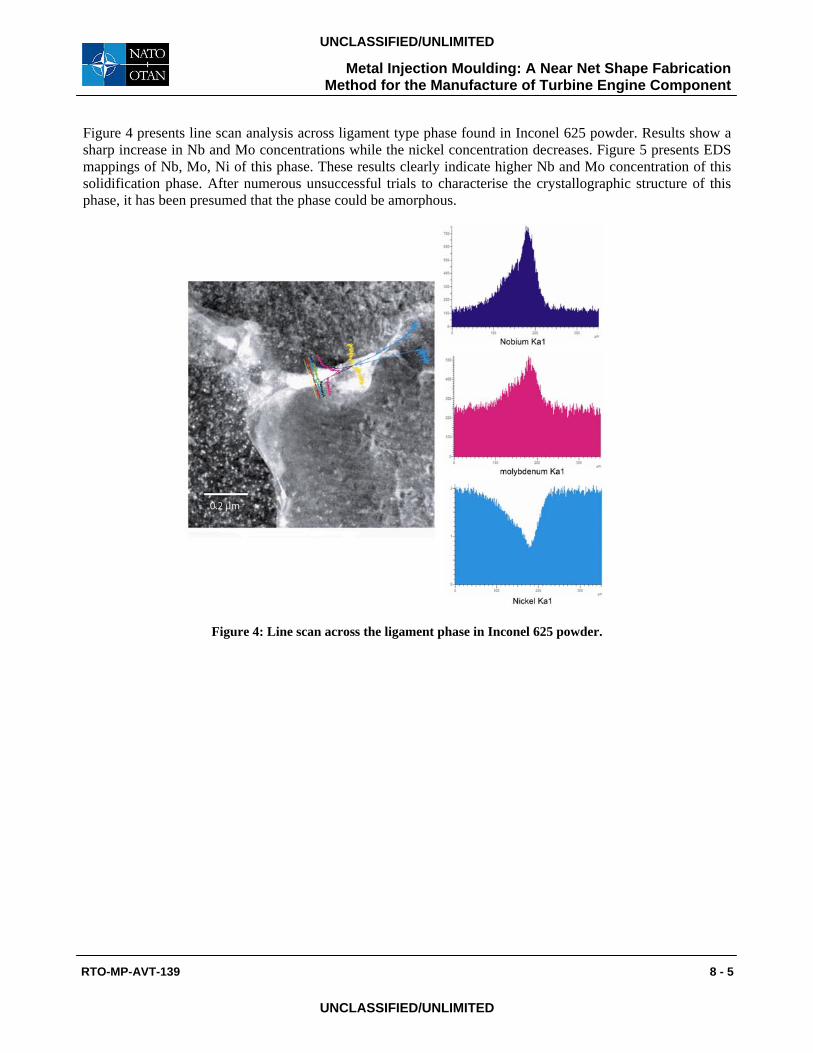
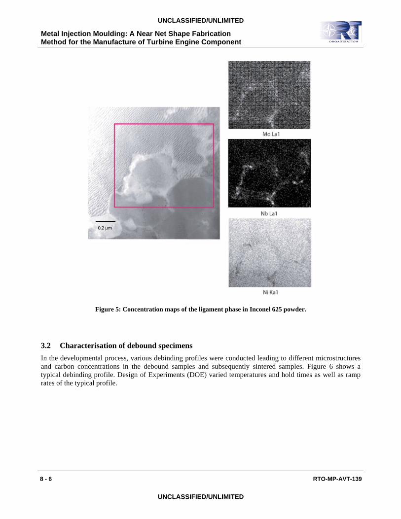
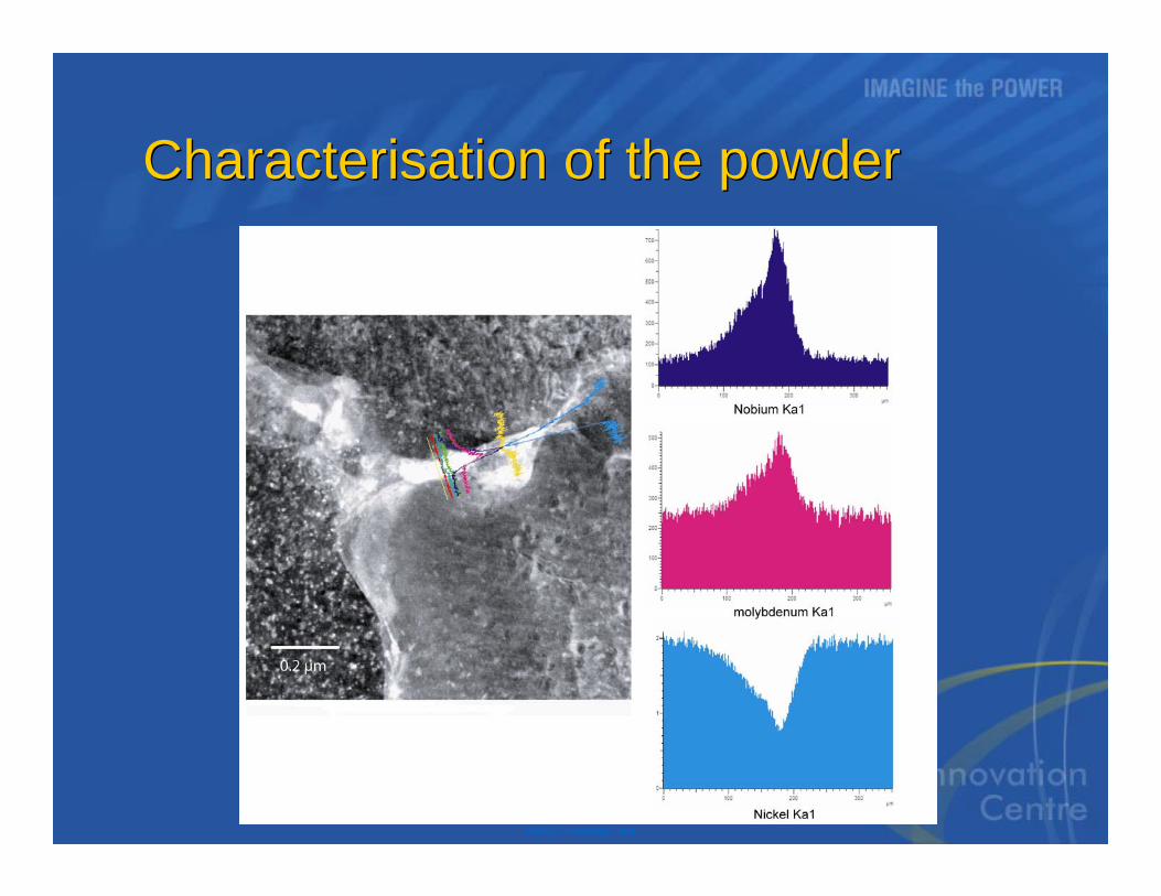
Figure 4 presents line scan analysis across ligament type phase found in Inconel 625 powder. Results show a sharp increase in Nb and Mo concentrations while the nickel concentration decreases. Figure 5 presents EDS mappings of Nb, Mo, Ni of this phase. These results clearly indicate higher Nb and Mo concentration of this solidification phase. After numerous unsuccessful trials to characterise the crystallographic structure of this phase, it has been presumed that the phase could be amorphous.
Figure 4: Line scan across the ligament phase in Inconel 625 powder.
Metal Injection Moulding: A Near Net Shape Fabrication Method for the Manufacture of Turbine Engine Component
8 - 6 RTO-MP-AVT-139
UNCLASSIFIED/UNLIMITED
UNCLASSIFIED/UNLIMITED
Figure 5: Concentration maps of the ligament phase in Inconel 625 powder.
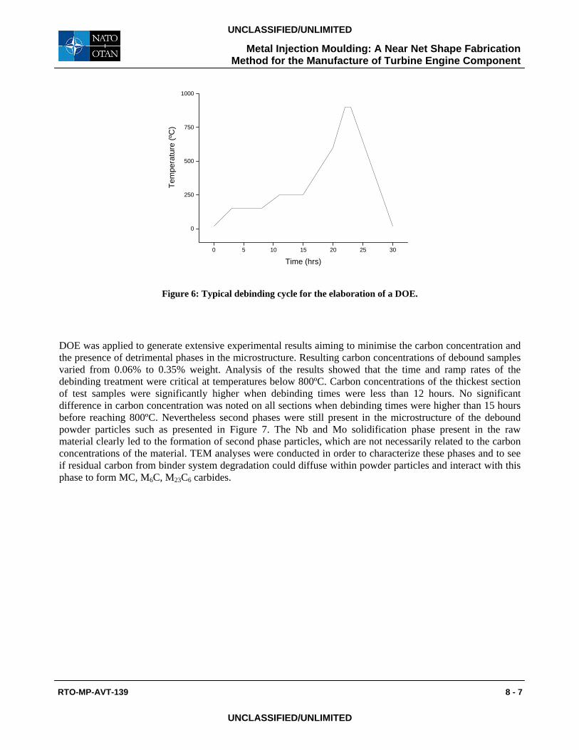
3.2 Characterisation of debound specimens In the developmental process, various debinding profiles were conducted leading to different microstructures and carbon concentrations in the debound samples and subsequently sintered samples. Figure 6 shows a typical debinding profile. Design of Experiments (DOE) varied temperatures and hold times as well as ramp rates of the typical profile.
Metal Injection Moulding: A Near Net Shape Fabrication Method for the Manufacture of Turbine Engine Component
RTO-MP-AVT-139 8 - 7
UNCLASSIFIED/UNLIMITED
UNCLASSIFIED/UNLIMITED
0 5 10 15 20 25 30
0
250
500
750
1000
Tem
pera
ture
(ºC
)
Time (hrs)
Figure 6: Typical debinding cycle for the elaboration of a DOE.
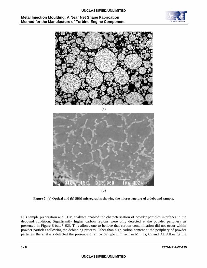
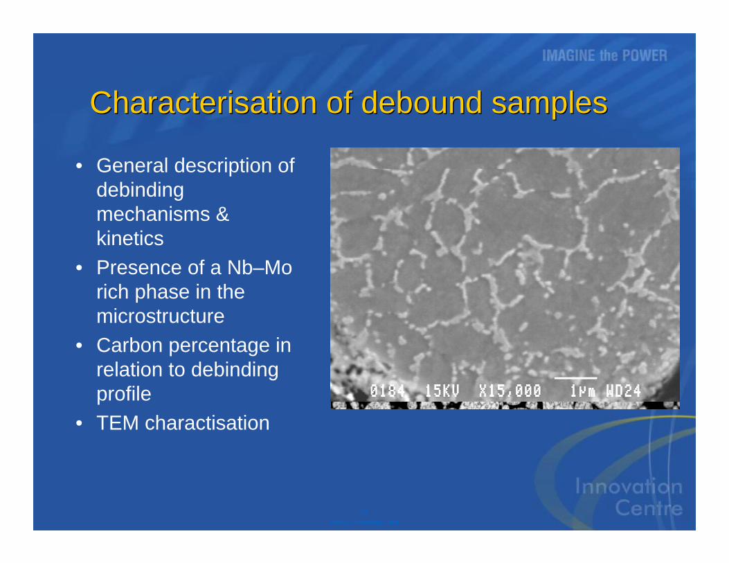
DOE was applied to generate extensive experimental results aiming to minimise the carbon concentration and the presence of detrimental phases in the microstructure. Resulting carbon concentrations of debound samples varied from 0.06% to 0.35% weight. Analysis of the results showed that the time and ramp rates of the debinding treatment were critical at temperatures below 800ºC. Carbon concentrations of the thickest section of test samples were significantly higher when debinding times were less than 12 hours. No significant difference in carbon concentration was noted on all sections when debinding times were higher than 15 hours before reaching 800ºC. Nevertheless second phases were still present in the microstructure of the debound powder particles such as presented in Figure 7. The Nb and Mo solidification phase present in the raw material clearly led to the formation of second phase particles, which are not necessarily related to the carbon concentrations of the material. TEM analyses were conducted in order to characterize these phases and to see if residual carbon from binder system degradation could diffuse within powder particles and interact with this phase to form MC, M6C, M23C6 carbides.
Metal Injection Moulding: A Near Net Shape Fabrication Method for the Manufacture of Turbine Engine Component
8 - 8 RTO-MP-AVT-139
UNCLASSIFIED/UNLIMITED
UNCLASSIFIED/UNLIMITED
(a)
(b)
Figure 7: (a) Optical and (b) SEM micrographs showing the microstructure of a debound sample.
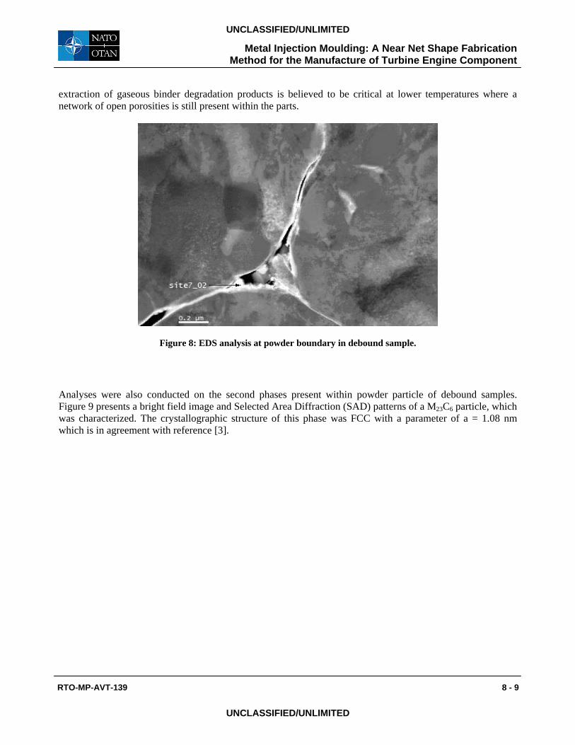
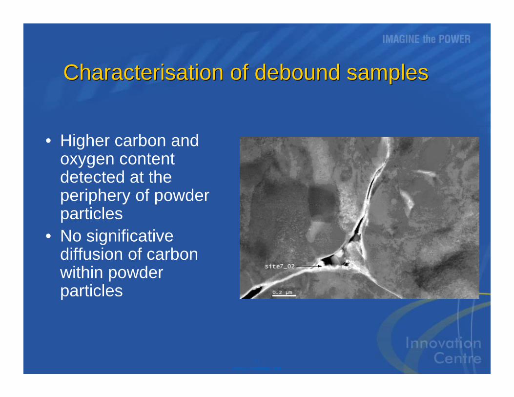
FIB sample preparation and TEM analyses enabled the characterisation of powder particles interfaces in the debound condition. Significantly higher carbon regions were only detected at the powder periphery as presented in Figure 8 (site7_02). This allows one to believe that carbon contamination did not occur within powder particles following the debinding process. Other than high carbon content at the periphery of powder particles, the analysis detected the presence of an oxide type film rich in Mn, Ti, Cr and Al. Allowing the
Metal Injection Moulding: A Near Net Shape Fabrication Method for the Manufacture of Turbine Engine Component
RTO-MP-AVT-139 8 - 9
UNCLASSIFIED/UNLIMITED
UNCLASSIFIED/UNLIMITED
extraction of gaseous binder degradation products is believed to be critical at lower temperatures where a network of open porosities is still present within the parts.
Figure 8: EDS analysis at powder boundary in debound sample.
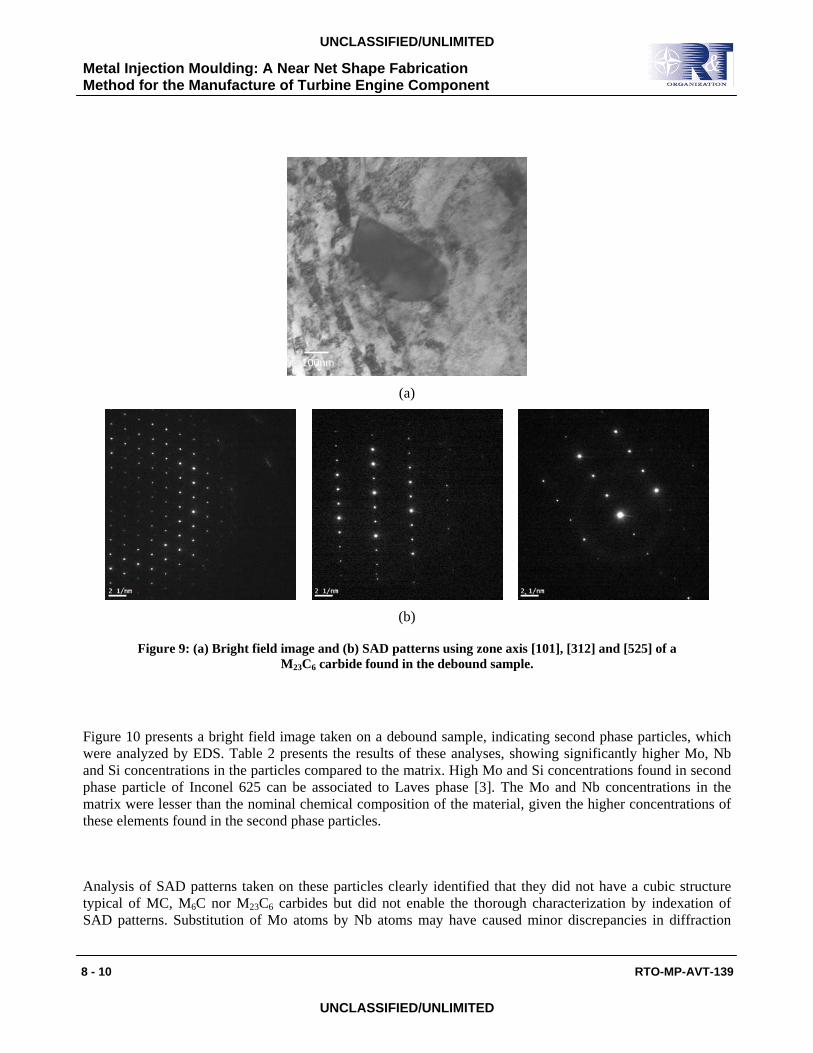
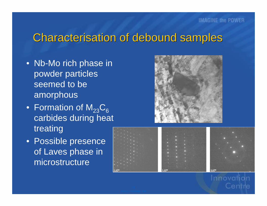
Analyses were also conducted on the second phases present within powder particle of debound samples. Figure 9 presents a bright field image and Selected Area Diffraction (SAD) patterns of a M23C6 particle, which was characterized. The crystallographic structure of this phase was FCC with a parameter of a = 1.08 nm which is in agreement with reference [3].
Metal Injection Moulding: A Near Net Shape Fabrication Method for the Manufacture of Turbine Engine Component
8 - 10 RTO-MP-AVT-139
UNCLASSIFIED/UNLIMITED
UNCLASSIFIED/UNLIMITED
(a)
(b)
Figure 9: (a) Bright field image and (b) SAD patterns using zone axis [101], [312] and [525] of a M23C6 carbide found in the debound sample.
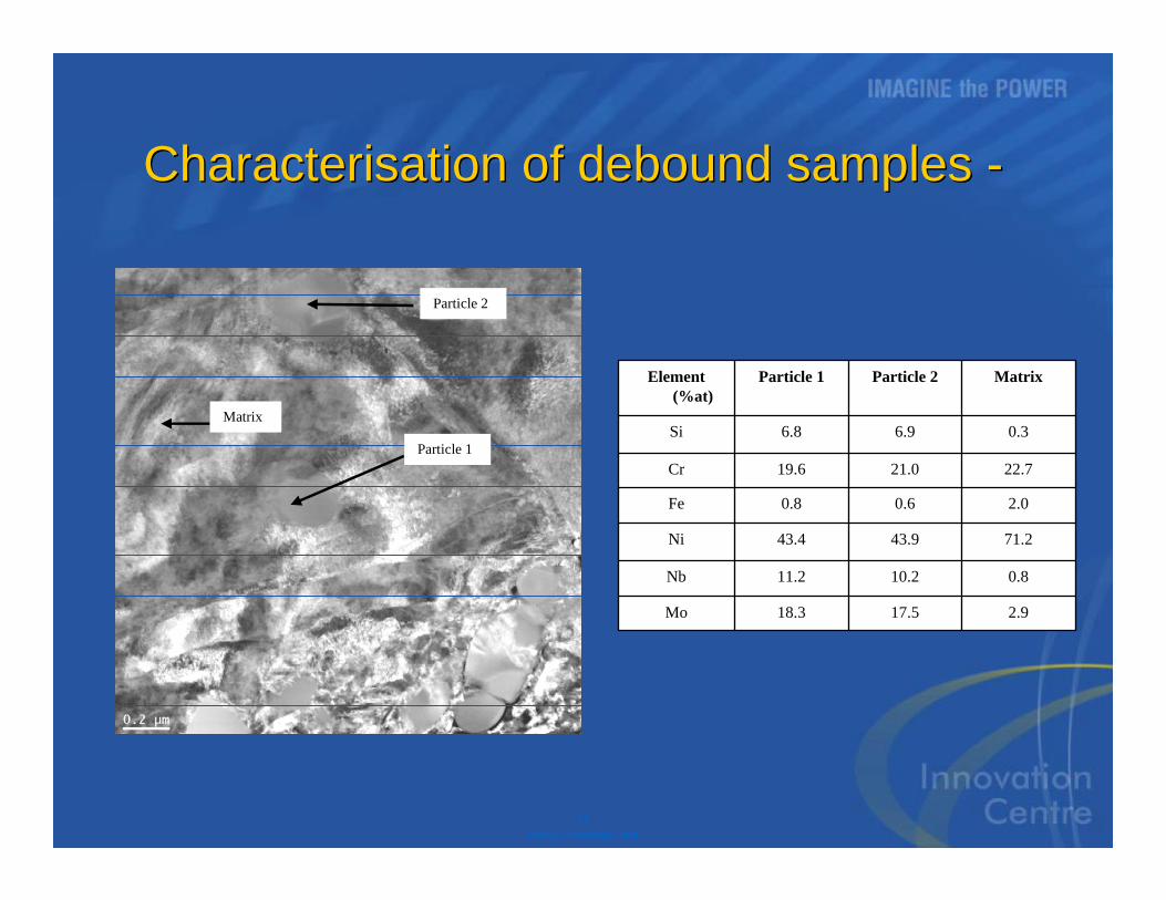
Figure 10 presents a bright field image taken on a debound sample, indicating second phase particles, which were analyzed by EDS. Table 2 presents the results of these analyses, showing significantly higher Mo, Nb and Si concentrations in the particles compared to the matrix. High Mo and Si concentrations found in second phase particle of Inconel 625 can be associated to Laves phase [3]. The Mo and Nb concentrations in the matrix were lesser than the nominal chemical composition of the material, given the higher concentrations of these elements found in the second phase particles.
Analysis of SAD patterns taken on these particles clearly identified that they did not have a cubic structure typical of MC, M6C nor M23C6 carbides but did not enable the thorough characterization by indexation of SAD patterns. Substitution of Mo atoms by Nb atoms may have caused minor discrepancies in diffraction
100nm

Metal Injection Moulding: A Near Net Shape Fabrication Method for the Manufacture of Turbine Engine Component
RTO-MP-AVT-139 8 - 11
UNCLASSIFIED/UNLIMITED
UNCLASSIFIED/UNLIMITED
patterns and complicated the characterization. Further work will be conducted on these particles to properly identify crystal structure. Nevertheless, previous studies [3] show that high Mo and Si concentrations are typical of Laves phase.
Figure 10: Bright field image of debound sample showing where EDS spectra were taken.
Table 2: Concentrations of elements of indicated areas on Figure 10.
Element (%at)
Particle 1 Particle 2 Matrix
Si 6.8 6.9 0.3
Cr 19.6 21.0 22.7
Fe 0.8 0.6 2.0
Ni 43.4 43.9 71.2
Nb 11.2 10.2 0.8
Mo 18.3 17.5 2.9
Particle 1
Particle 2
Matrix
Metal Injection Moulding: A Near Net Shape Fabrication Method for the Manufacture of Turbine Engine Component
8 - 12 RTO-MP-AVT-139
UNCLASSIFIED/UNLIMITED
UNCLASSIFIED/UNLIMITED
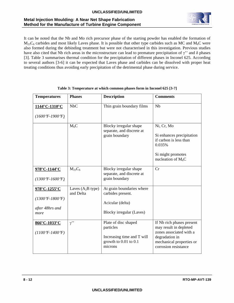
It can be noted that the Nb and Mo rich precursor phase of the starting powder has enabled the formation of M23C6 carbides and most likely Laves phase. It is possible that other type carbides such as MC and M6C were also formed during the debinding treatment but were not characterised in this investigation. Previous studies have also cited that Nb rich areas in the microstructure can lead to premature precipitation of γ’’ and δ phases [3]. Table 3 summarises thermal condition for the precipitation of different phases in Inconel 625. According to several authors [3-6] it can be expected that Laves phase and carbides can be dissolved with proper heat treating conditions thus avoiding early precipitation of the detrimental phase during service.
Table 3: Temperature at which common phases form in Inconel 625 [3-7]
Temperatures Phases Description Comments
1144°C-1310°C
(1600°F-1900°F)
NbC Thin grain boundary films Nb
M6C Blocky irregular shape separate, and discrete at grain boundary
Ni, Cr, Mo
Si enhances precipitation if carbon is less than 0.035%
Si might promotes nucleation of M6C
978°C-1144°C
(1300°F-1600°F)
M23C6 Blocky irregular shape separate, and discrete at grain boundary
Cr
978°C-1255°C
(1300°F-1800°F)
after 48hrs and more
Laves (A2B type) and Delta
At grain boundaries where carbides present.
Acicular (delta)
Blocky irregular (Laves)
866°C-1033°C
(1100°F-1400°F)
γ’’ Plate of disc shaped particles
Increasing time and T will growth to 0.01 to 0.1 microns
If Nb rich phases present may result in depleted zones associated with a degradation in mechanical properties or corrosion resistance
Metal Injection Moulding: A Near Net Shape Fabrication Method for the Manufacture of Turbine Engine Component
RTO-MP-AVT-139 8 - 13
UNCLASSIFIED/UNLIMITED
UNCLASSIFIED/UNLIMITED
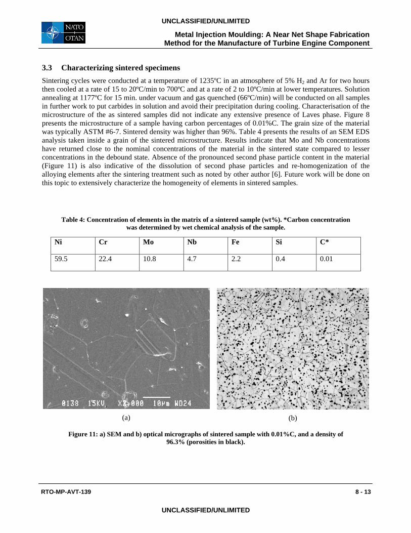
3.3 Characterizing sintered specimens Sintering cycles were conducted at a temperature of 1235ºC in an atmosphere of 5% H2 and Ar for two hours then cooled at a rate of 15 to 20ºC/min to 700ºC and at a rate of 2 to 10ºC/min at lower temperatures. Solution annealing at 1177ºC for 15 min. under vacuum and gas quenched (66ºC/min) will be conducted on all samples in further work to put carbides in solution and avoid their precipitation during cooling. Characterisation of the microstructure of the as sintered samples did not indicate any extensive presence of Laves phase. Figure 8 presents the microstructure of a sample having carbon percentages of 0.01%C. The grain size of the material was typically ASTM #6-7. Sintered density was higher than 96%. Table 4 presents the results of an SEM EDS analysis taken inside a grain of the sintered microstructure. Results indicate that Mo and Nb concentrations have returned close to the nominal concentrations of the material in the sintered state compared to lesser concentrations in the debound state. Absence of the pronounced second phase particle content in the material (Figure 11) is also indicative of the dissolution of second phase particles and re-homogenization of the alloying elements after the sintering treatment such as noted by other author [6]. Future work will be done on this topic to extensively characterize the homogeneity of elements in sintered samples.
Table 4: Concentration of elements in the matrix of a sintered sample (wt%). *Carbon concentration was determined by wet chemical analysis of the sample.
Ni Cr Mo Nb Fe Si C*
59.5 22.4 10.8 4.7 2.2 0.4 0.01
(a)
(b)
Figure 11: a) SEM and b) optical micrographs of sintered sample with 0.01%C, and a density of 96.3% (porosities in black).
Metal Injection Moulding: A Near Net Shape Fabrication Method for the Manufacture of Turbine Engine Component
8 - 14 RTO-MP-AVT-139
UNCLASSIFIED/UNLIMITED
UNCLASSIFIED/UNLIMITED
4 CONCLUSIONS This study addressed the processing of Inconel 625 powder by LPIM for the fabrication of small complex shape parts used in gas turbine applications. Characterization of the microstructure was extensively studied on the starting powder and debound samples. The following conclusions were taken:
• Characterization of the starting powder revealed the presence of a Nb and Mo rich phase in the microstructure which became the precursor of discrete second phase particles found in the debound samples. TEM examination of the debound samples enabled the proper identification of M23C6 carbides and possibly Laves phase;
• Thermal debinding in an atmosphere of argon proved to be beneficial for eliminating the bi-products of polymer degradation and for avoiding carbon contamination of the debound material. Carbon levels as low as 0.06% were achieved for thermal profiles which span 15 hours before reaching the temperature of 800ºC;
• The sintering cycle enabled the dissolution of second phase particles in the microstructure and promoted homogenization of the alloying elements. An average grain size of ASTM #6-7 and a sintered density of 96% theoretical were generated with the standard sintering cycle. Further work will be conducted on the sintering of Inconel 625 LPIM feedstock.
5 ACKNOWLEDGEMENTS: This work has been conducted within Pratt & Withney Canada corp. Innovation Centre. We would like to thank Mr. Vincent Savaria and researchers of the CM2 at Ecole Polytechnique of Montreal for their precious help in conducting metallurgical characterisation of produced specimens.
Metal Injection Moulding: A Near Net Shape Fabrication Method for the Manufacture of Turbine Engine Component
RTO-MP-AVT-139 8 - 15
UNCLASSIFIED/UNLIMITED
UNCLASSIFIED/UNLIMITED
6 REFERENCES
[1] Davidson, J.H., (1991), The Influence of Processing Variables on the Microstructure and Properties of PM 625 Alloy, Superalloys 718, 625, 706 and Various Derivatives, ed. E.A. Loria, The Minerals, Metals & Materials Society
[2] Valencia, J.J., McCabe, T., Hens, K., Hansen, J.O., Bose, A., (1994), Microstructure and Mechanical Properties of Inconel 625 and 718 Alloys Processed by Powder Injection Molding, Superalloys 718, 625, 706 and Various Derivatives, ed. E.A. Loria, The Minerals, Metals & Materials Society.
[3] Floreen, S., Fuchs, G.E., Yang, W.K, (1994), The Metallurgy of Alloy 625, Superalloys 718, 625, 706 and Various Derivatives, ed. E.A. Loria, The Minerals, Metals & Materials Society.
[4] Shankar V., Bhanu Sankara Rao, K., Mannan, S.L., (2001), Microstructure and mechanical properties of Inconel 625 superalloy, Journal of Nuclear Materials, 288, 222-232.
[5] Shankar V., Valsan, M., Bhanu Sankara Rao, K., Mannan, S.L., (2004), Effects of temperature and Strain Rate on Tensile Properties and Activation Energy for Dynamic Strain Aging in Alloy 625, Metallurgical and Materials Transactions A, col.35A, 3129-3139.
[6] Valencia, J.J., Spirko, J., Schmees, R., (1997), Sintering Effect on the Microstructure and Mechanical Properties of Alloy 718 Processed by Powder Injection Molding, Superalloys 718, 625, 706 and Various Derivatives, ed. E.A. Loria, The Minerals, Metals & Materials Society.
[7] Ferrer, L., Pieraggi, B., Uginet, J.F., (1991), Microstructural Evolution During Thermomechanical Processing of Alloy 625, Superalloys 718, 625, 706 and Various Derivatives, ed. E.A. Loria, The Minerals, Metals & Materials Society.

Metal Injection Moulding: A Near Net Shape Fabrication Method for the Manufacture of Turbine Engine Component
8 - 16 RTO-MP-AVT-139
UNCLASSIFIED/UNLIMITED
UNCLASSIFIED/UNLIMITED
MEETING DISCUSSION – PAPER NO: 8
Author: B. Julien
Discusser: P. Kobryn
Question: Have you considered the impact of residual porosity on fatigue behavior? If so, what is the impact?
Response: Yes, characterization of the impact of residual porosities on fatigue and L.C.F. properties will be studied in the near future.
Discusser: C. Bampton
Question: Is there any liquid phase present during the sintering?
Response: Sintering at a temperature of 1245 ◦C under argon + 5% hydrogen did not lead to the formation of a liquid phase. Sintering at 1260 ◦C under the same atmosphere did induce some incipient melting.
Discusser: J. P. Immarigeon
Question: How far away are you from rig testing or engine testing of MIMed parts?
Response: Sorry, this information cannot be disclosed.
1P&WC Proprietary Data
Metal Injection Moulding: A Near Net Shape Fabrication Method for the
Manufacture of Turbine EngineComponents
Metal Injection Moulding: A Near Net Shape Fabrication Method for the
Manufacture of Turbine EngineComponents
NATO - AVT 139May 16, 2006
Benoît Julien Mélissa Després
Maetta Sciences inc. Pratt & Whitney Canada Corp.
2P&WC Proprietary Data
Presentation contentPresentation content
• Introduction• Experimental procedures• Results• Conclusion• Question period
3P&WC Proprietary Data
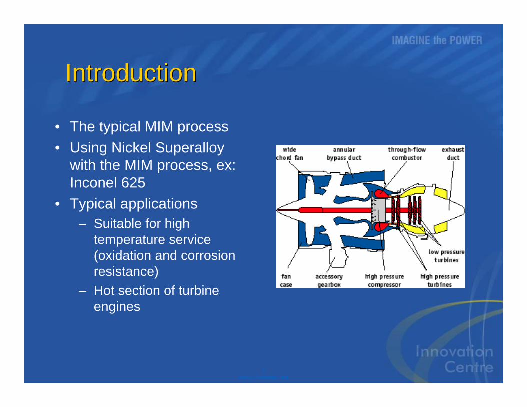
IntroductionIntroduction
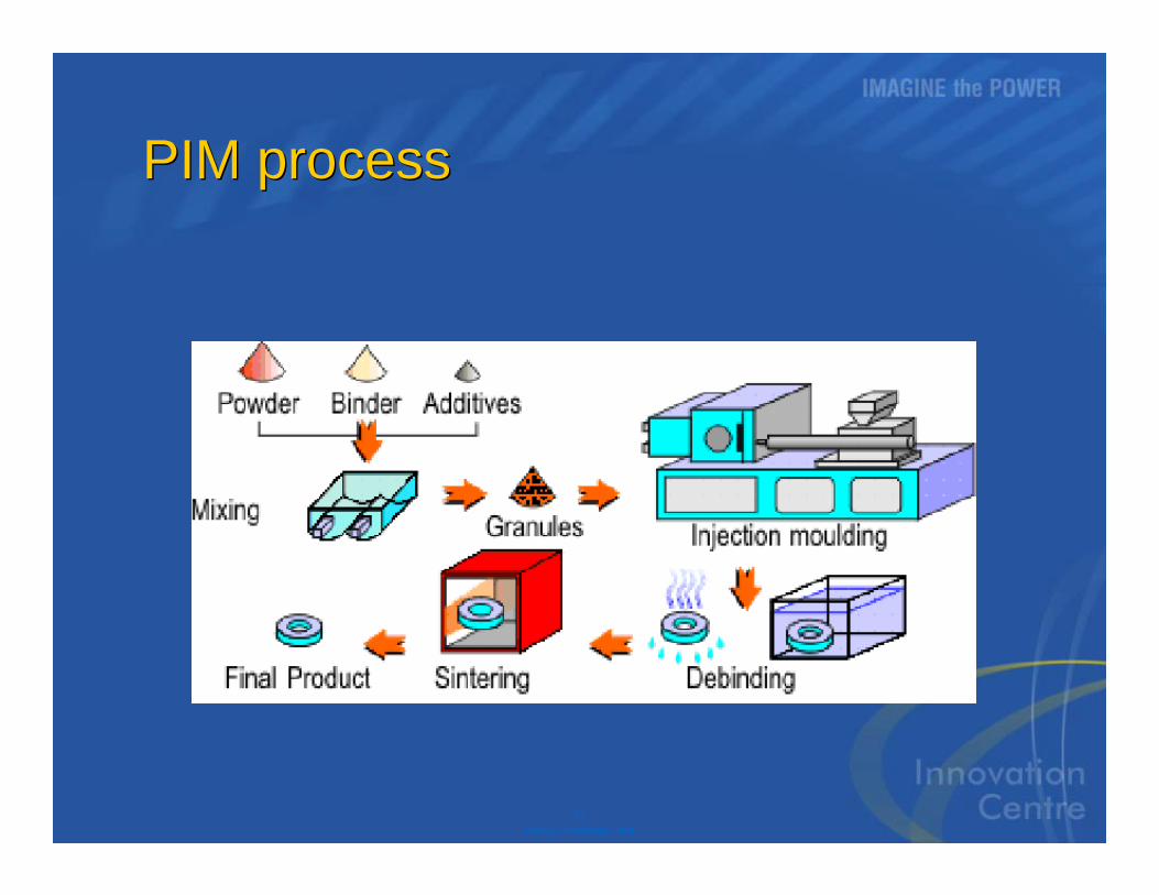
• The typical MIM process• Using Nickel Superalloy
with the MIM process, ex: Inconel 625
• Typical applications– Suitable for high
temperature service (oxidation and corrosion resistance)
– Hot section of turbine engines
4P&WC Proprietary Data
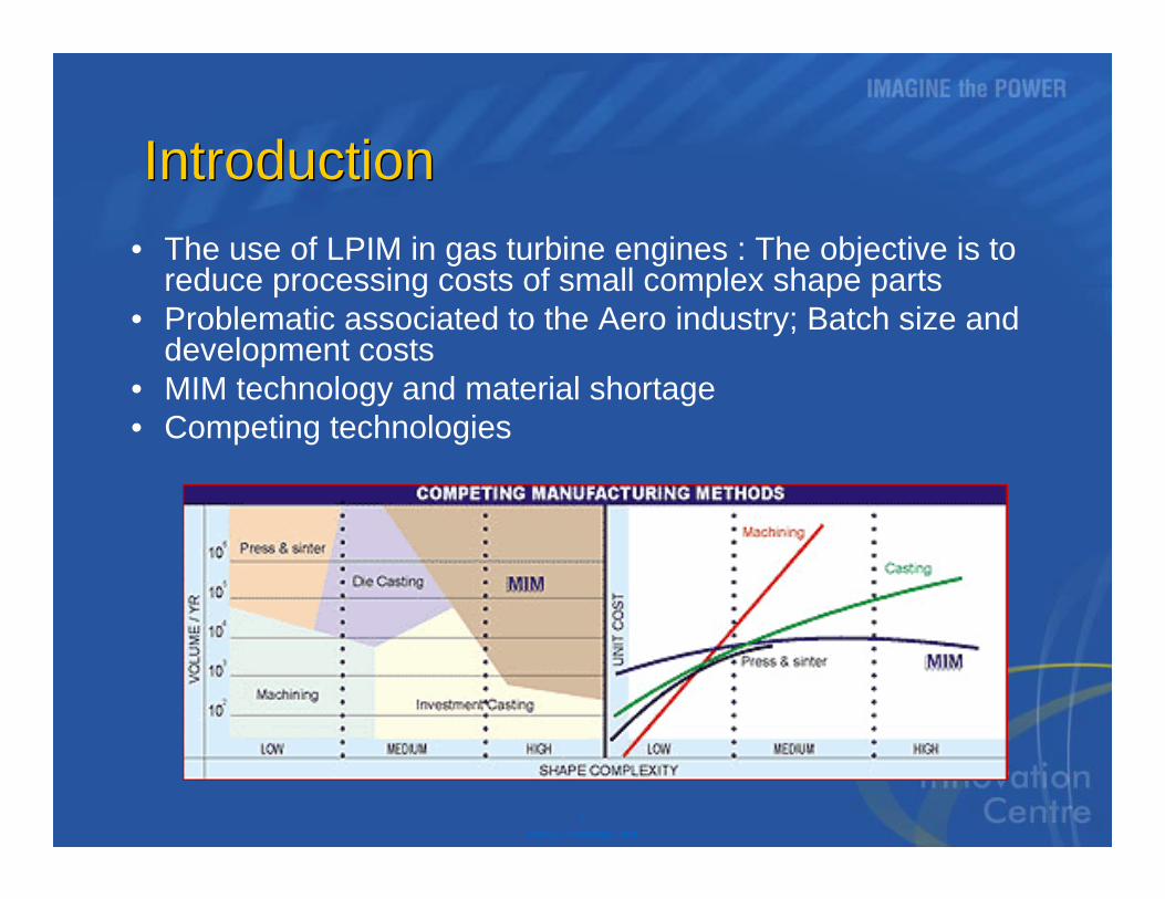
IntroductionIntroduction• The use of LPIM in gas turbine engines : The objective is to
reduce processing costs of small complex shape parts• Problematic associated to the Aero industry; Batch size and
development costs• MIM technology and material shortage• Competing technologies
5P&WC Proprietary Data
Experimental proceduresExperimental procedures
• Raw material –Inconel 625 powder
• Proprietary binder system and injection technology
• Characterisation work mostly on microstructure, physical and chemical properties
6P&WC Proprietary Data
Characterisation of the powderCharacterisation of the powder
• Characterisation of the microstructure of powders - SEM & TEM
• Solidification paths for IN625 atomized powder
– Nb-Mo rich eutectic phase
7P&WC Proprietary Data
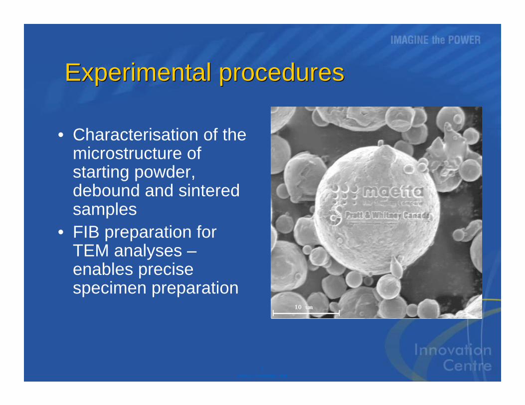
Experimental proceduresExperimental procedures
• Characterisation of the microstructure of starting powder, debound and sintered samples
• FIB preparation for TEM analyses –enables precise specimen preparation
8P&WC Proprietary Data
Characterisation of the powderCharacterisation of the powder
9P&WC Proprietary Data
Debinding conditionsDebinding conditions
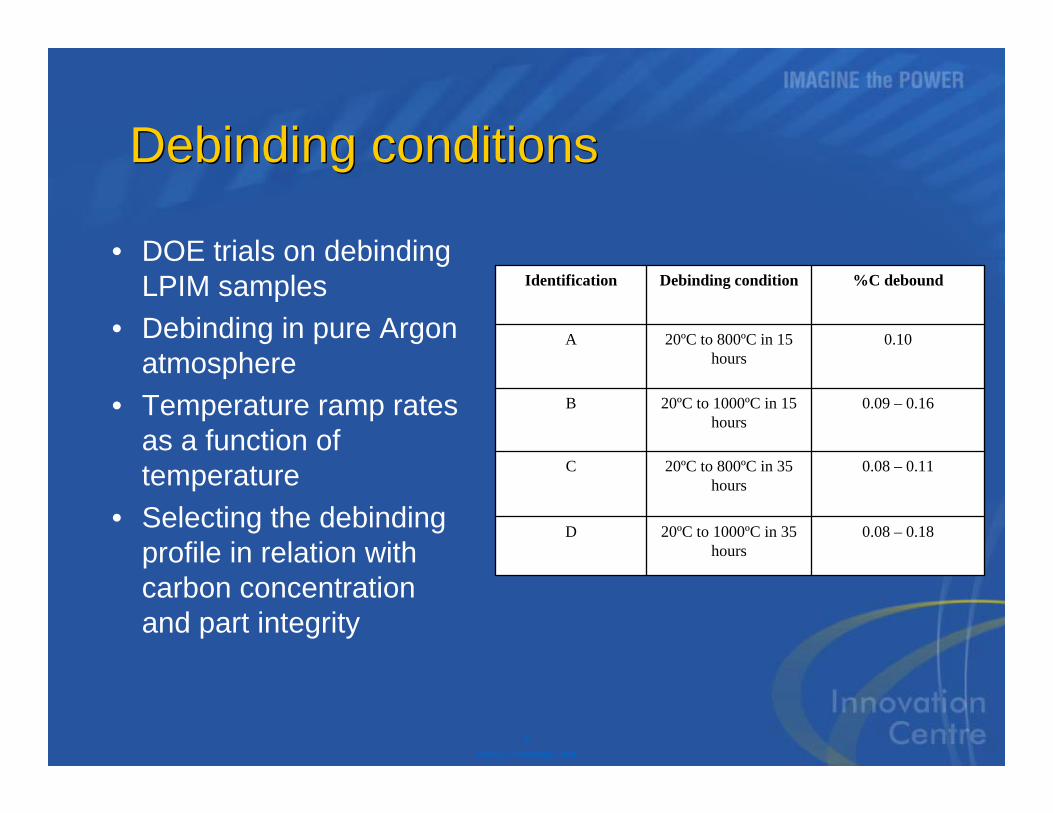
• DOE trials on debindingLPIM samples
• Debinding in pure Argon atmosphere
• Temperature ramp rates as a function oftemperature
• Selecting the debindingprofile in relation withcarbon concentration and part integrity
0.08 – 0.1820ºC to 1000ºC in 35 hours
D
0.08 – 0.1120ºC to 800ºC in 35 hours
C
0.09 – 0.1620ºC to 1000ºC in 15 hours
B
0.1020ºC to 800ºC in 15 hours
A
%C deboundDebinding conditionIdentification
10P&WC Proprietary Data
Characterisation of debound samplesCharacterisation of debound samples
• General description of debindingmechanisms & kinetics
• Presence of a Nb–Mo rich phase in the microstructure
• Carbon percentage in relation to debindingprofile
• TEM charactisation
11P&WC Proprietary Data
Characterisation of debound samplesCharacterisation of debound samples
• Higher carbon andoxygen content detected at theperiphery of powderparticles
• No significative diffusion of carbonwithin powderparticles
12P&WC Proprietary Data
Characterisation of debound samplesCharacterisation of debound samples
• Nb-Mo rich phase in powder particlesseemed to beamorphous
• Formation of M23C6carbides during heattreating
• Possible presenceof Laves phase in microstructure
100 nm
13P&WC Proprietary Data
Characterisation of debound samples -Characterisation of debound samples -
Particle 1
Particle 2
Matrix
2.917.518.3Mo
0.810.211.2Nb
71.243.943.4Ni
2.00.60.8Fe
22.721.019.6Cr
0.36.96.8Si
MatrixParticle 2Particle 1Element (%at)
14P&WC Proprietary Data
Characterisation of sintered samplesCharacterisation of sintered samples
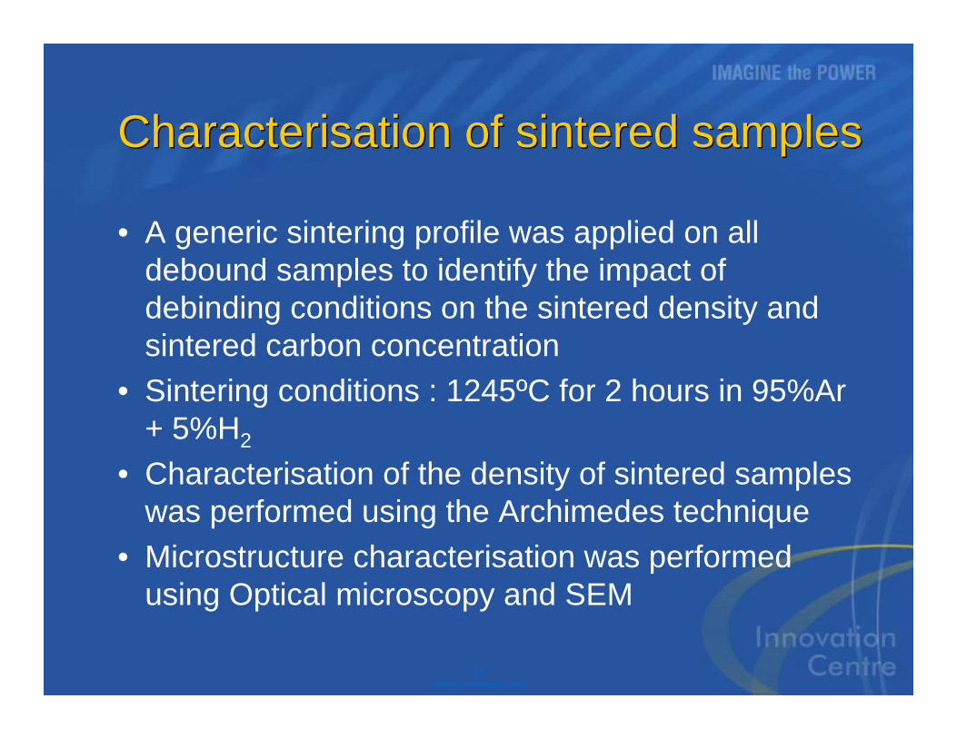
• A generic sintering profile was applied on all debound samples to identify the impact of debinding conditions on the sintered density and sintered carbon concentration
• Sintering conditions : 1245ºC for 2 hours in 95%Ar + 5%H2
• Characterisation of the density of sintered samples was performed using the Archimedes technique
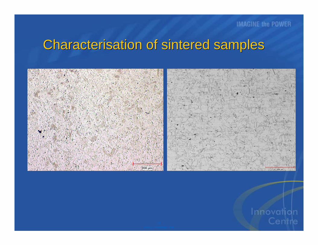
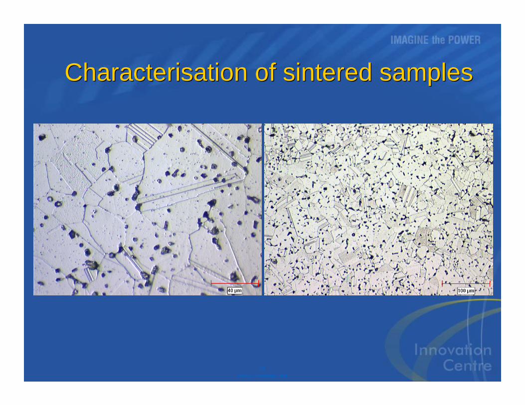
• Microstructure characterisation was performed using Optical microscopy and SEM
15P&WC Proprietary Data
Characterisation of sintered samples Characterisation of sintered samples
16P&WC Proprietary Data
Characterisation of sintered samplesCharacterisation of sintered samples
17P&WC Proprietary Data
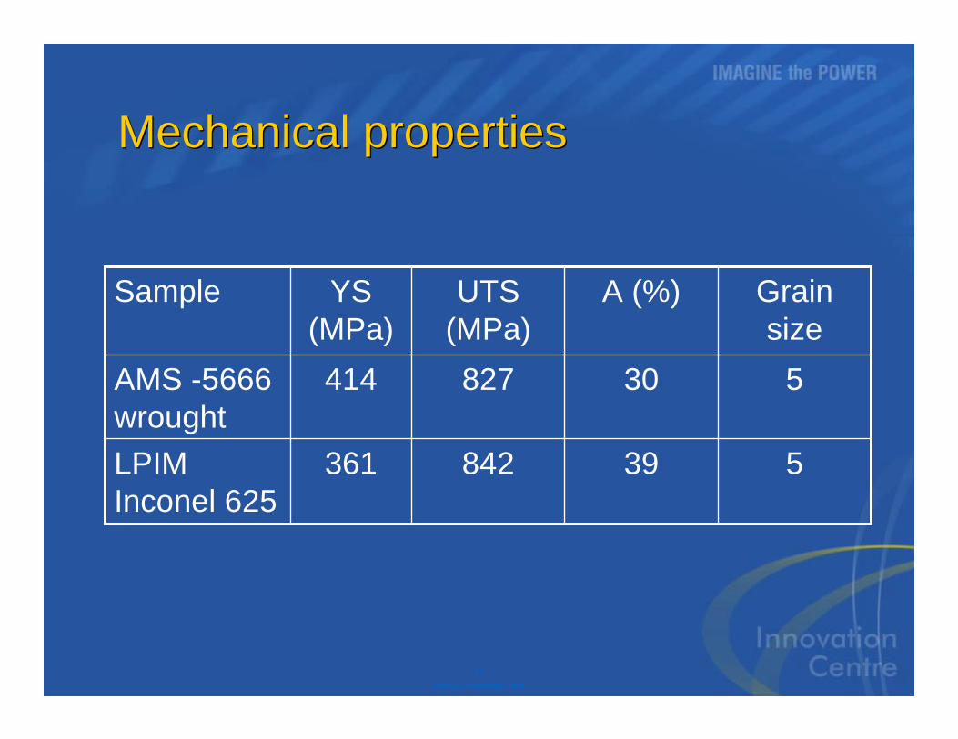
Mechanical propertiesMechanical properties
539842361LPIM Inconel 625
530827414AMS -5666 wrought
Grain size
A (%)UTS (MPa)
YS (MPa)
Sample
18P&WC Proprietary Data
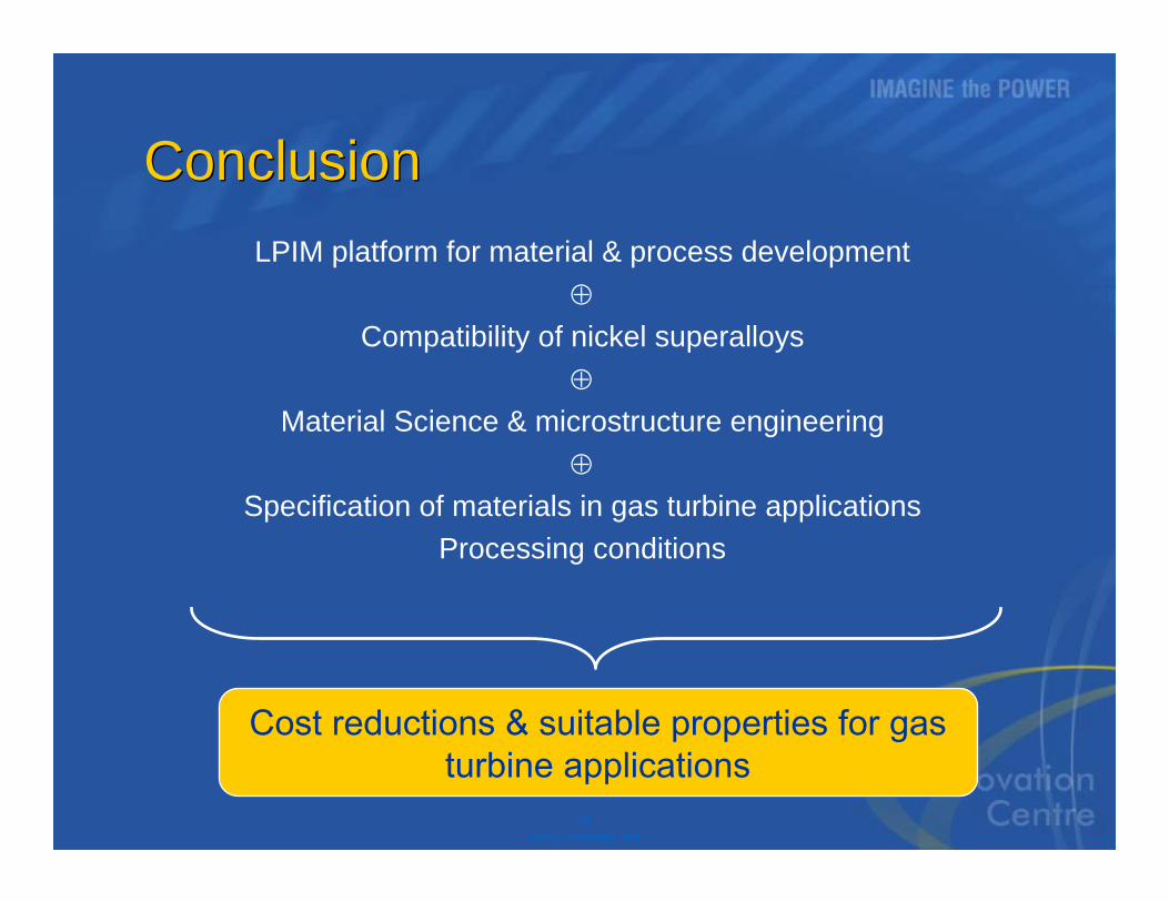
ConclusionConclusionLPIM platform for material & process development
Compatibility of nickel superalloys
Material Science & microstructure engineering
Specification of materials in gas turbine applications
Processing conditions
Cost reductions & suitable properties for gas turbine applications

19P&WC Proprietary Data
Question periodQuestion period
20P&WC Proprietary Data
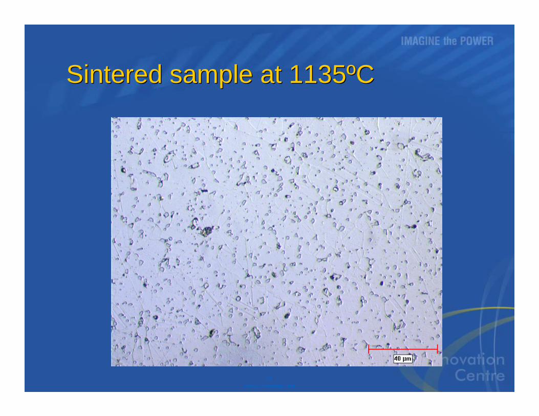
Sintered sample at 1135ºCSintered sample at 1135ºC
21P&WC Proprietary Data
PIM processPIM process
22P&WC Proprietary Data
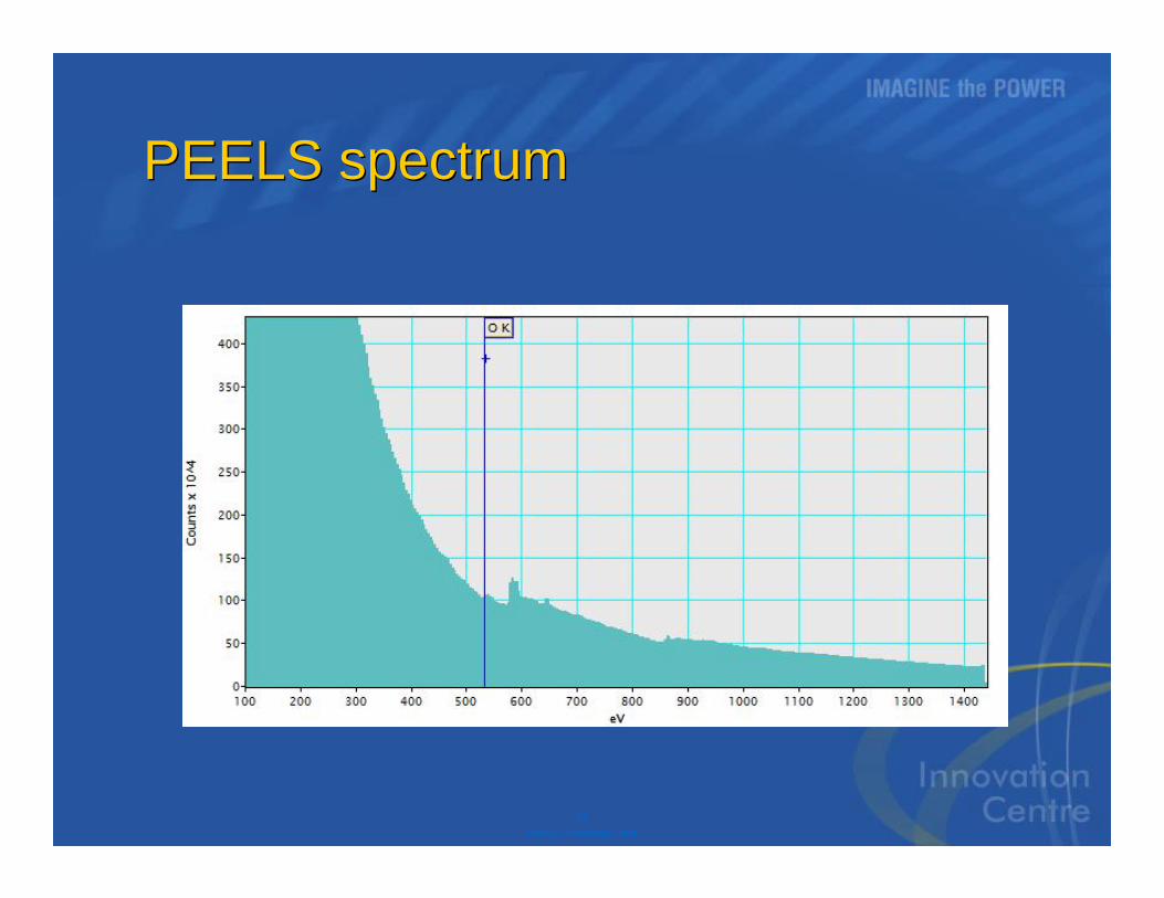
PEELS spectrumPEELS spectrum