metal backing flanges for use with polyethylene (pe) pipe flange
TRANSCRIPT
Industry
Guidelines
METAL BACKING FLANGES FOR
USE WITH POLYETHYLENE (PE)
PIPE FLANGE ADAPTORS
ISSUE 2.5
Ref: POP007
27 May 2015
POP007 ISSUE 2.5 Page 1
Disclaimer
In formulating this guideline PIPA has relied upon the advice of its members and,
where appropriate, independent testing.
Notwithstanding, users of the guidelines are advised to seek their own independent
advice and, where appropriate, to conduct their own testing and assessment of
matters contained in the guidelines, and to not rely solely on the guidelines in
relation to any matter that may risk loss or damage.
PIPA gives no warranty concerning the correctness of accuracy of the information,
opinions and recommendations contained in the guidelines. Users of the guidelines
are advised that their reliance on any matter contained in the guidelines is at their
own risk.
//
POP007 ISSUE 2.5 Page 2
METAL BACKING FLANGES FOR USE WITH POLYETHYLENE (PE)
PIPE FLANGE ADAPTORS
The primary aim of this document is to provide guidance relating to the geometric
specification of metal backing flanges suitable for the use with PE flange adaptors in
the sizes DN20 through to DN1000 and flanges in accordance with AS 2129,
ANSI/ASTM B16.5, AS/NZS 4331.1 (ISO 7005-1) and AS 4087.
Also included are references to corrosion protection, marking, temperature rerating,
gasket selection and installation – including bolt tensioning. This guidance is not a
selection guide for these aspects but rather highlights areas that a specifier of a PE
flange joint should consider when making an informed choice about flange joint
assemblies.
NOTE: The thicknesses for backing flanges noted in the tables are applicable to
steel. Different metals demand different thicknesses for the same performance, so for
metals other than steel, consideration must be given to thickness.
Although Tables 4, 5, 6 and 7 in these guidelines make reference to pressure ratings
(PN/Class), these pressure ratings are nominal only, and advice from the flange
manufacturer should be sought to clarify the actual pressure rating of the assembly.
1. BACKGROUND
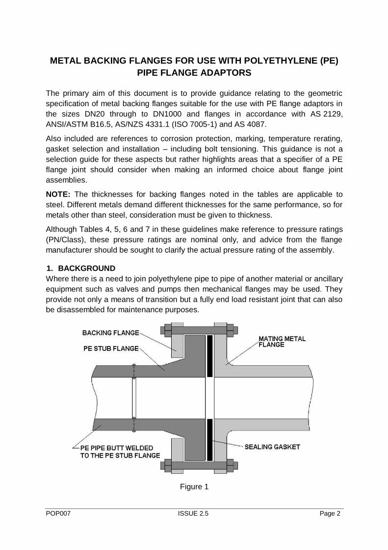
Where there is a need to join polyethylene pipe to pipe of another material or ancillary
equipment such as valves and pumps then mechanical flanges may be used. They
provide not only a means of transition but a fully end load resistant joint that can also
be disassembled for maintenance purposes.
Figure 1
POP007 ISSUE 2.5 Page 3
2. NON-CONFORMING FLANGES
The flange dimensions listed in this guideline conform to the Standards nominated.
Flanges with reduced thickness are used by industry for non-critical, low performance
applications and are not recommended by PIPA.
The following information applies to the ensuing tables in the document:
As per ISO 9624: “The inside diameter of the loose backing flange shall conform to
the design of the flange adaptor. In some applications, values of the inside diameter
of the loose backing flange differing from those given in the tables may be used.”
POP007 ISSUE 2.5 Page 4
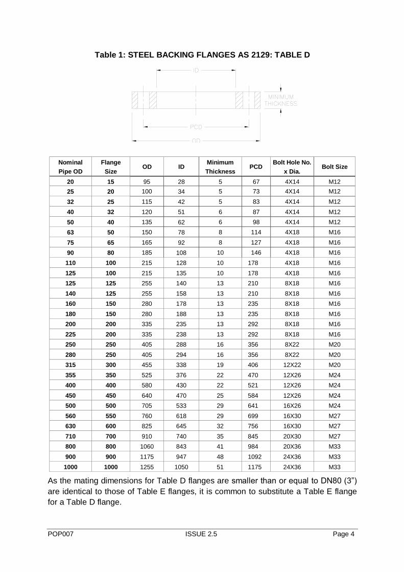
Table 1: STEEL BACKING FLANGES AS 2129: TABLE D
Nominal
Pipe OD
Flange
Size OD ID
Minimum
Thickness PCD
Bolt Hole No.
x Dia. Bolt Size
20 15 95 28 5 67 4X14 M12
25 20 100 34 5 73 4X14 M12
32 25 115 42 5 83 4X14 M12
40 32 120 51 6 87 4X14 M12
50 40 135 62 6 98 4X14 M12
63 50 150 78 8 114 4X18 M16
75 65 165 92 8 127 4X18 M16
90 80 185 108 10 146 4X18 M16
110 100 215 128 10 178 4X18 M16
125 100 215 135 10 178 4X18 M16
125 125 255 140 13 210 8X18 M16
140 125 255 158 13 210 8X18 M16
160 150 280 178 13 235 8X18 M16
180 150 280 188 13 235 8X18 M16
200 200 335 235 13 292 8X18 M16
225 200 335 238 13 292 8X18 M16
250 250 405 288 16 356 8X22 M20
280 250 405 294 16 356 8X22 M20
315 300 455 338 19 406 12X22 M20
355 350 525 376 22 470 12X26 M24
400 400 580 430 22 521 12X26 M24
450 450 640 470 25 584 12X26 M24
500 500 705 533 29 641 16X26 M24
560 550 760 618 29 699 16X30 M27
630 600 825 645 32 756 16X30 M27
710 700 910 740 35 845 20X30 M27
800 800 1060 843 41 984 20X36 M33
900 900 1175 947 48 1092 24X36 M33
1000 1000 1255 1050 51 1175 24X36 M33
As the mating dimensions for Table D flanges are smaller than or equal to DN80 (3”)
are identical to those of Table E flanges, it is common to substitute a Table E flange
for a Table D flange.
POP007 ISSUE 2.5 Page 5
As the thicknesses of these flanges differ, and therefore the pressure rating of the
flange, care should be taken to ensure the pressure rating of the flange used is
suitable for the system which it is being used on.
POP007 ISSUE 2.5 Page 6
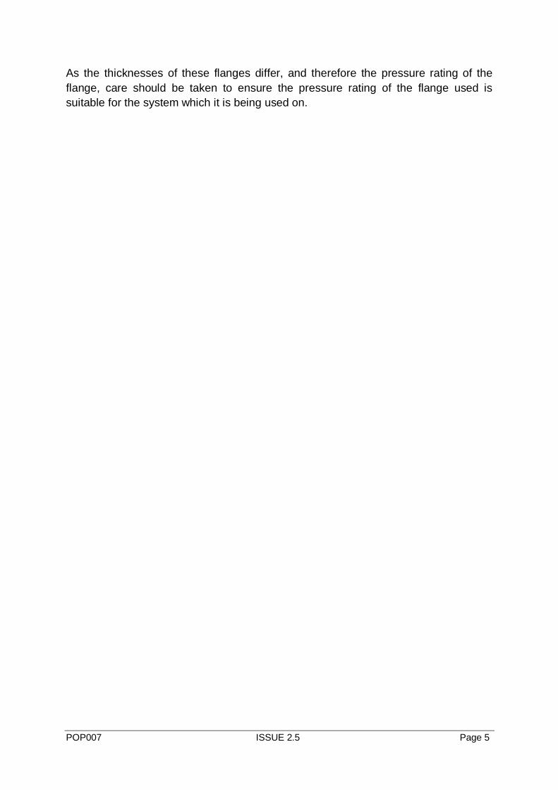
Table 2: STEEL BACKING FLANGES AS 2129: TABLE E
Nominal
Pipe OD
Flange
Size OD ID
Minimum
Thickness PCD
Bolt Hole
No. x Dia. Bolt Size
20 15 95 28 6 67 4X14 M12
25 20 100 34 6 73 4X14 M12
32 25 115 42 7 83 4X14 M12
40 32 120 51 8 87 4X14 M12
50 40 135 62 9 98 4X14 M12
63 50 150 78 10 114 4X18 M16
75 65 165 92 10 127 4X18 M16
90 80 185 108 11 146 4X18 M16
110 100 215 128 13 178 8X18 M16
125 100 215 135 13 178 8X18 M16
125 125 255 140 14 210 8X18 M16
140 125 255 158 14 210 8X18 M16
160 150 280 178 17 235 8X22 M20
180 150 280 188 17 235 8X22 M20
200 200 335 235 19 292 8X22 M20
225 200 335 238 19 292 8X22 M20
250 250 405 288 22 356 12X22 M20
280 250 405 294 22 356 12X22 M20
315 300 455 338 25 406 12X26 M24
355 350 525 376 29 470 12X26 M24
400 400 580 430 32 521 12X26 M24
450 450 640 470 35 584 16X26 M24
500 500 705 533 38 641 16X26 M24
560 550 760 618 44 699 16X30 M27
630 600 825 645 48 756 16X33 M30
710 700 910 740 51 845 20X33 M30
800 800 1060 843 54 984 20X36 M33
900 900 1175 947 64 1092 24X36 M33
1000 1000 1255 1050 67 1175 24X39 M36
POP007 ISSUE 2.5 Page 7
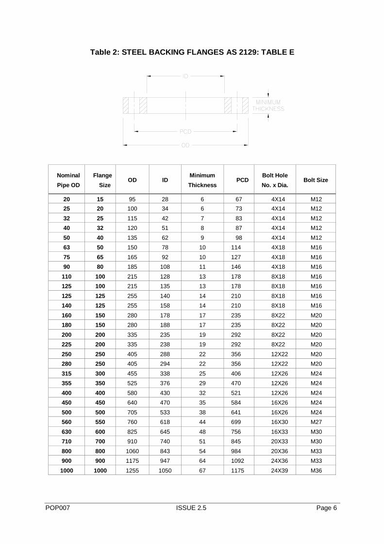
Table 3: STEEL BACKING FLANGES A.N.S.I. 150
Nominal
Pipe OD
Flange
Size OD ID
Minimum
Thickness PCD
Bolt Hole No.
x Dia. Bolt Size
20 ½” 90 28 11.2 60.5 4X16 M14
25 ¾’
98 34 12.8 70 4X16 M14
32 1” 108 42 14.2 79.5 4X16 M14
40 1 ¼” 117 51 15.7 89 4X16 M14
50 1 ½” 127 62 17.5 98.5 4X16 M14
63 2” 152 78 19.0 120.5 4X20 M18
75 2 1/2” 178 92 22.3 139.5 4X20 M18
90 3” 191 108 23.9 152 4X20 M18
110 4” 229 128 23.9 190.5 8X20 M18
125 5” 254 135 23.9 216 8X22 M20
140 5” 254 158 23.9 216 8X22 M20
160 6” 279 178 25.4 241 8X22 M20
180 6” 279 188 25.4 241 8X22 M20
200 8” 343 235 28.4 298.5 8X22 M20
225 8” 343 238 28.4 298.5 8X22 M20
250 10” 406 288 30.2 362 12X26 M24
280 10” 406 294 30.2 362 12X26 M24
315 12” 482 338 31.8 432 12X26 M24
355 14” 533 376 35.0 476 12X30 M27
400 16” 600 430 36.6 540 16X30 M27
450 18” 635 470 39.6 578 16X33 M30
500 20” 700 533 43.0 635 20X33 M30
630 24” 815 645 47.8 750 20X36 M33
POP007 ISSUE 2.5 Page 8
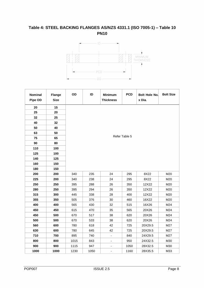
Table 4: STEEL BACKING FLANGES AS/NZS 4331.1 (ISO 7005-1) – Table 10
PN10
Nominal
Pipe OD
Flange
Size
OD ID Minimum
Thickness
PCD Bolt Hole No.
x Dia.
Bolt Size
20 15
25 20
32 25
40 32
50 40
63 50
Refer Table 5 75 65
90 80
110 100
125 100
140 125
160 150
180 150
200 200 340 235 24 295 8X22 M20
225 200 340 238 24 295 8X22 M20
250 250 395 288 26 350 12X22 M20
280 250 395 294 26 350 12X22 M20
315 300 445 338 28 400 12X22 M20
355 350 505 376 30 460 16X22 M20
400 400 565 430 32 515 16X26 M24
450 450 615 470 35 565 20X26 M24
450 500 670 517 38 620 20X26 M24
500 500 670 533 38 620 20X26 M24
560 600 780 618 42 725 20X29.5 M27
630 600 780 645 42 725 20X29.5 M27
710 700 895 740 - 840 24X29.5 M27
800 800 1015 843 - 950 24X32.5 M30
900 900 1115 947 - 1050 28X32.5 M30
1000 1000 1230 1050 - 1160 28X35.5 M33
POP007 ISSUE 2.5 Page 9
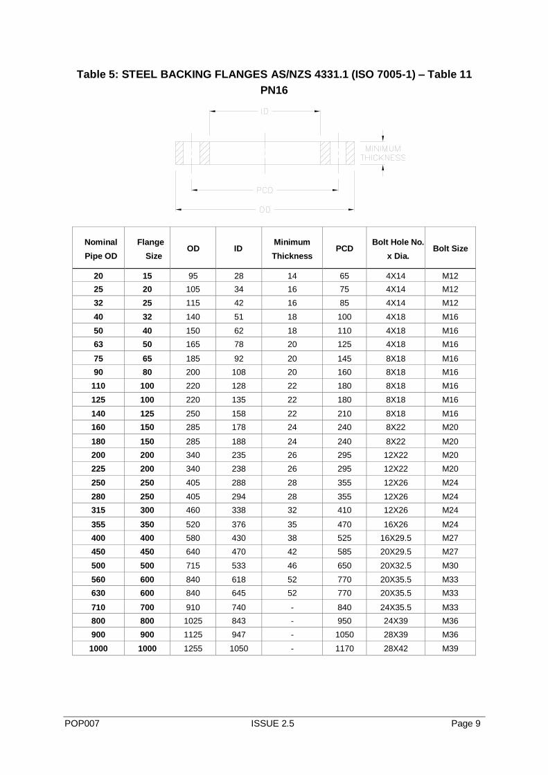
Table 5: STEEL BACKING FLANGES AS/NZS 4331.1 (ISO 7005-1) – Table 11
PN16
Nominal
Pipe OD
Flange
Size OD ID
Minimum
Thickness PCD
Bolt Hole No.
x Dia. Bolt Size
20 15 95 28 14 65 4X14 M12
25 20 105 34 16 75 4X14 M12
32 25 115 42 16 85 4X14 M12
40 32 140 51 18 100 4X18 M16
50 40 150 62 18 110 4X18 M16
63 50 165 78 20 125 4X18 M16
75 65 185 92 20 145 8X18 M16
90 80 200 108 20 160 8X18 M16
110 100 220 128 22 180 8X18 M16
125 100 220 135 22 180 8X18 M16
140 125 250 158 22 210 8X18 M16
160 150 285 178 24 240 8X22 M20
180 150 285 188 24 240 8X22 M20
200 200 340 235 26 295 12X22 M20
225 200 340 238 26 295 12X22 M20
250 250 405 288 28 355 12X26 M24
280 250 405 294 28 355 12X26 M24
315 300 460 338 32 410 12X26 M24
355 350 520 376 35 470 16X26 M24
400 400 580 430 38 525 16X29.5 M27
450 450 640 470 42 585 20X29.5 M27
500 500 715 533 46 650 20X32.5 M30
560 600 840 618 52 770 20X35.5 M33
630 600 840 645 52 770 20X35.5 M33
710 700 910 740 - 840 24X35.5 M33
800 800 1025 843 - 950 24X39 M36
900 900 1125 947 - 1050 28X39 M36
1000 1000 1255 1050 - 1170 28X42 M39
POP007 ISSUE 2.5 Page 10
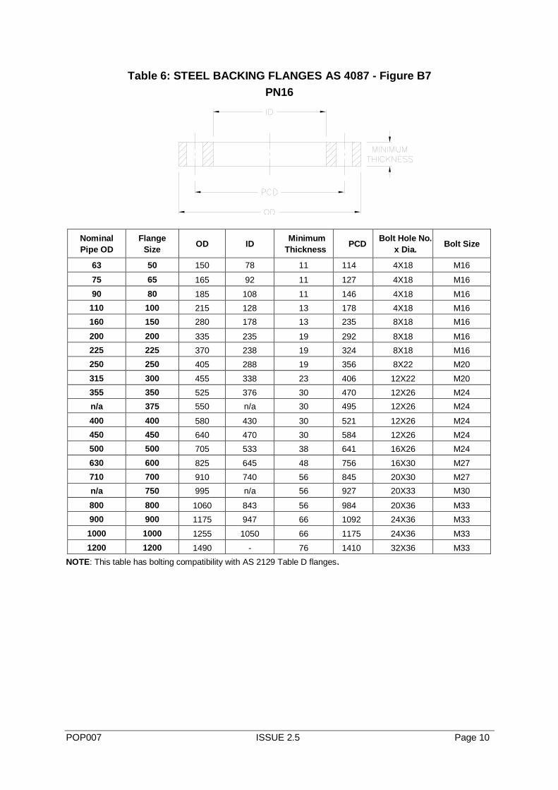
Table 6: STEEL BACKING FLANGES AS 4087 - Figure B7
PN16
Nominal
Pipe OD
Flange
Size OD ID
Minimum
Thickness PCD
Bolt Hole No.
x Dia. Bolt Size
63 50 150 78 11 114 4X18 M16
75 65 165 92 11 127 4X18 M16
90 80 185 108 11 146 4X18 M16
110 100 215 128 13 178 4X18 M16
160 150 280 178 13 235 8X18 M16
200 200 335 235 19 292 8X18 M16
225 225 370 238 19 324 8X18 M16
250 250 405 288 19 356 8X22 M20
315 300 455 338 23 406 12X22 M20
355 350 525 376 30 470 12X26 M24
n/a 375 550 n/a 30 495 12X26 M24
400 400 580 430 30 521 12X26 M24
450 450 640 470 30 584 12X26 M24
500 500 705 533 38 641 16X26 M24
630 600 825 645 48 756 16X30 M27
710 700 910 740 56 845 20X30 M27
n/a 750 995 n/a 56 927 20X33 M30
800 800 1060 843 56 984 20X36 M33
900 900 1175 947 66 1092 24X36 M33
1000 1000 1255 1050 66 1175 24X36 M33
1200 1200 1490 - 76 1410 32X36 M33
NOTE: This table has bolting compatibility with AS 2129 Table D flanges.
POP007 ISSUE 2.5 Page 11
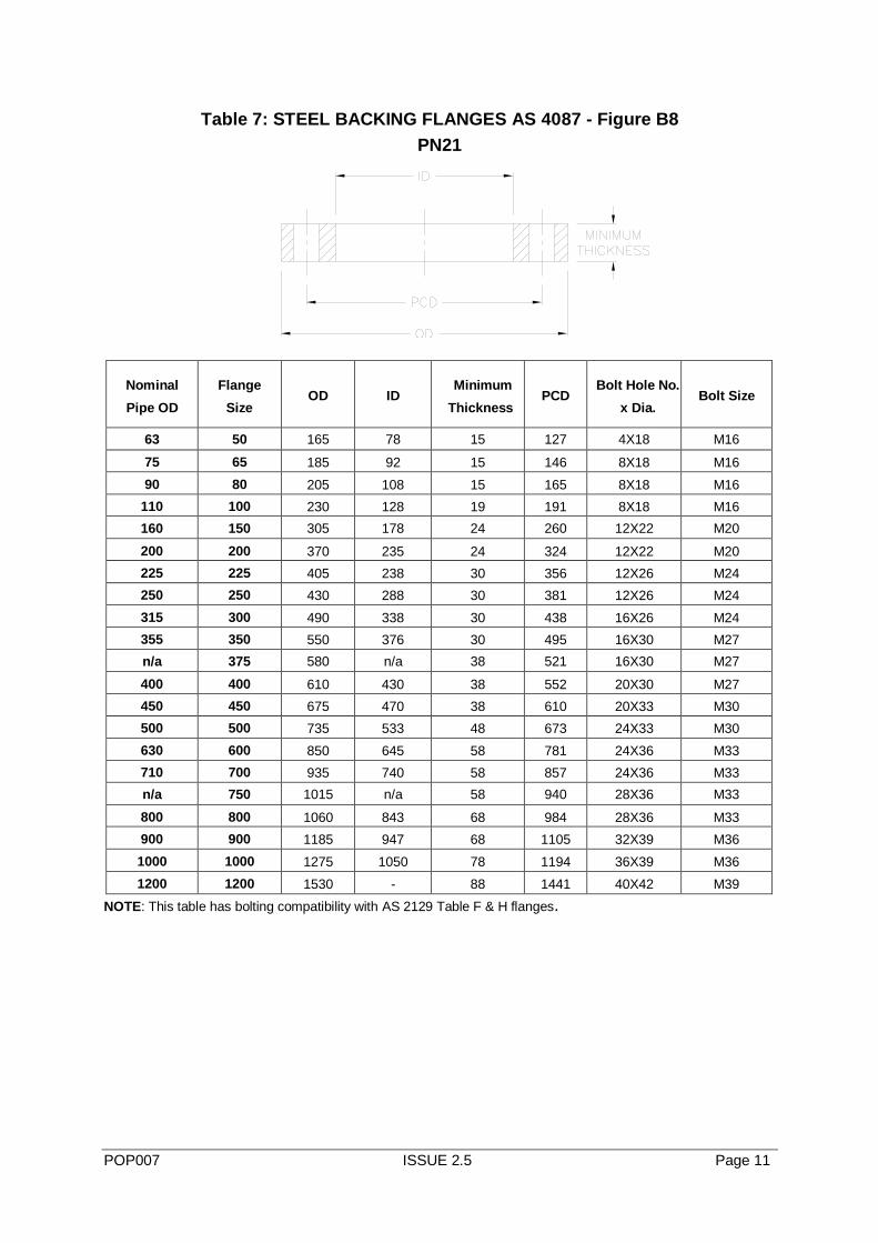
Table 7: STEEL BACKING FLANGES AS 4087 - Figure B8
PN21
Nominal
Pipe OD
Flange
Size OD ID
Minimum
Thickness PCD
Bolt Hole No.
x Dia. Bolt Size
63 50 165 78 15 127 4X18 M16
75 65 185 92 15 146 8X18 M16
90 80 205 108 15 165 8X18 M16
110 100 230 128 19 191 8X18 M16
160 150 305 178 24 260 12X22 M20
200 200 370 235 24 324 12X22 M20
225 225 405 238 30 356 12X26 M24
250 250 430 288 30 381 12X26 M24
315 300 490 338 30 438 16X26 M24
355 350 550 376 30 495 16X30 M27
n/a 375 580 n/a 38 521 16X30 M27
400 400 610 430 38 552 20X30 M27
450 450 675 470 38 610 20X33 M30
500 500 735 533 48 673 24X33 M30
630 600 850 645 58 781 24X36 M33
710 700 935 740 58 857 24X36 M33
n/a 750 1015 n/a 58 940 28X36 M33
800 800 1060 843 68 984 28X36 M33
900 900 1185 947 68 1105 32X39 M36
1000 1000 1275 1050 78 1194 36X39 M36
1200 1200 1530 - 88 1441 40X42 M39
NOTE: This table has bolting compatibility with AS 2129 Table F & H flanges.
POP007 ISSUE 2.5 Page 12
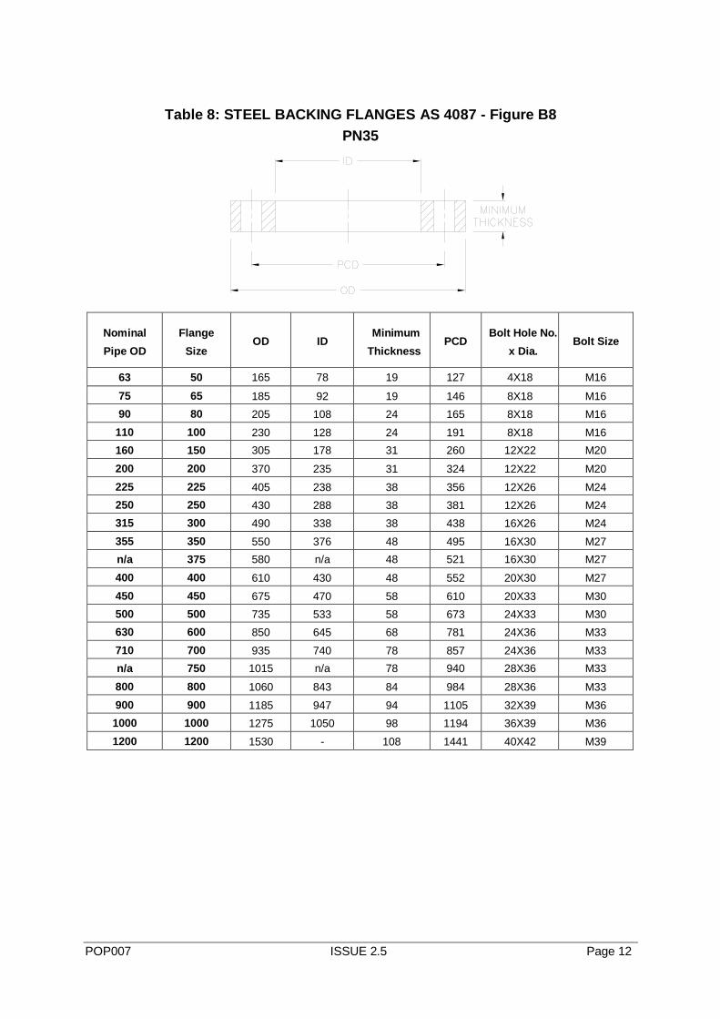
Table 8: STEEL BACKING FLANGES AS 4087 - Figure B8
PN35
Nominal
Pipe OD
Flange
Size OD ID
Minimum
Thickness PCD
Bolt Hole No.
x Dia. Bolt Size
63 50 165 78 19 127 4X18 M16
75 65 185 92 19 146 8X18 M16
90 80 205 108 24 165 8X18 M16
110 100 230 128 24 191 8X18 M16
160 150 305 178 31 260 12X22 M20
200 200 370 235 31 324 12X22 M20
225 225 405 238 38 356 12X26 M24
250 250 430 288 38 381 12X26 M24
315 300 490 338 38 438 16X26 M24
355 350 550 376 48 495 16X30 M27
n/a 375 580 n/a 48 521 16X30 M27
400 400 610 430 48 552 20X30 M27
450 450 675 470 58 610 20X33 M30
500 500 735 533 58 673 24X33 M30
630 600 850 645 68 781 24X36 M33
710 700 935 740 78 857 24X36 M33
n/a 750 1015 n/a 78 940 28X36 M33
800 800 1060 843 84 984 28X36 M33
900 900 1185 947 94 1105 32X39 M36
1000 1000 1275 1050 98 1194 36X39 M36
1200 1200 1530 - 108 1441 40X42 M39
POP007 ISSUE 2.5 Page 13
3. CORROSION PROTECTION
Flanges and fasteners should be coated in accordance with Australian standards or
codes such as AS/NZS 4680 for galvanising. Alternatively, stainless steel flanges and
fasteners can be used or flanges can be protected with polymeric coatings in
accordance with AS/NZS 4158 and be used in conjunction with stainless steel
fasteners.
4. MARKING
Flanges should be permanently and legibly marked either on the rim or on the back of
the flange between the rim and the pitch circle diameter.
Marking, at a minimum, should include;
Standard of the flange (AS2129/AS4087 etc)
Size of the flange (DN) (DN50 or 2” etc)
Rating of the flange (Table D/PN16 etc)
Material Grade
Manufacturer’s name or trademark
Identification, such as the heat or batch number, correlating the material test
certificate of the flange with the certificate of analysis of the material
The height of the lettering should be not less than 3mm for flanges less than 10mm
thickness, or 5mm for other flanges.
Where the marking is indented, low-stress (eg round nosed) stamps shall be used.
5. TEMPERATURE DERATING
Standards such as AS 2129, AS 4087 and ANSI B16.5 provide guidance as to the
working pressure of the backing flange at various temperatures. If the temperature is
outside the range listed in these standards, material pressure derating guidance can
be gained from standards such as ASME B31.1 and ASME B31.3
6. GASKETS
This guidance document is not a selection guide for gaskets but rather highlights
areas that a specifier of a PE flange joint should consider when making an informed
choice about which gasket (if any)should be used. It is recommended that specifiers
consult with the gasket supplier.
The following is a list highlighting elements of the application and joint assembly that
should be considered when selecting a suitable gasket. This list does not attempt to
cover all aspects and hence specifiers should not be limited to only those the aspects
raised below.
Aspects to consider in gasket selection:
Operating pressure, including surge allowance.
POP007 ISSUE 2.5 Page 14
The ability of the gasket to seal at the clamping pressure imposed and resist
blow-out without suffering excessive stress relaxation.
Operating temperature
Materials of mating flanges and the potential impact of surface finish, flatness,
surface roughness and coatings.
Compatibility of the gasket materials with the medium being transported within the
pipe at the operating temperatures and pressures. For flanged joints intended for
use with potable water the gasket material must comply with AS/NZS 4020.
Gaskets may not be necessary when using PE flanges provided sufficient
compressive load can be applied (i.e. sufficient bolt torque) and the sealing surfaces
are not excessively rough or damaged.
“In theory gaskets are not necessary to provide a seal with PE flanges since the
viscoelastic and creep properties of the polymer will ensure that the flange face is
forced into parallelism with its opposite number even under modest long term bolting
loads, and that the PE will “flow” into any surface imperfections and thus seal off
potential leakage paths” (High Integrity Polyethylene Stub Flange Connections, A.L
Headford, Stewarts and Lloyds Plastics).
Non-gasketed joints are common place in the US and to a lesser extent in the UK and
Europe. Historical Australian practice has been to use gaskets.
7. INSTALLATION
Caution - Since polyethylene pipe systems are end load bearing, care must be
taken where connection is made to pipe of another material, to prevent pullout
of any non-end-load bearing joints.
1) Ensure the backing flange is placed over the pipe before the stub flange is fused to the pipe.
2) Ensure the mating faces are clean and free for contamination and damage.
3) Pipework configuration shall be such that the mating faces are in true alignment and butted square to each other prior to bolting up.
4) The gasket must be centred properly between the two flanges before tightening commences.
5) The nuts and bolts must be progressively tightened and as uniformly possible in a diagonally opposite sequence.
8. Bolt Torque - General
The range of application conditions, bolt types, use or otherwise of lubricants and
combination of possible gasket and non-gasketed PE flange assemblies makes it
impractical to nominate bolt torques that are applicable for all applications.
POP007 ISSUE 2.5 Page 15
The bolt torque to be specified for a specific installation is an aspect that is highly
dependent on the gasket type being used (or indeed no gasket if that option is
appropriate).
In practice bolt torque is the most commonly used method of quantifying the applied
sealing force. There are however, many variables in terms of achieving the required
sealing force on the joint using torque control as the indicator.
In operation, the tightening process exerts an axial pre-load tension on the bolt. This
tension load is equal and opposite to the compression force applied on the
assembled components.
“When using torque control as the method for establishing flange assembly pre-load,
one must understand there is a measurable variance between applied torque and
theoretical bolt tension. Typically, only about 10% to 20 % of the applied torque is
actually transmitted into bolt elongation. From tests, it is known that about 50% of the
bolt torque is consumed by friction from the bolt-head contact face or the nut-face
being rotated against its mating part. About 10% is used up in reversible twist of the
bolt length. About another 30% is dissipated to overcome the friction in the bolt/nut
threads. When more torque is needed to overcome friction, then less remains for bolt
extension pre-load. Hence, small changes to reduce friction on the bolt-threads and
under the rotating nut-face, will significantly increase the torque transmitted to bolt-
extension pre-load “(Bolt Torque for Polyethylene Flanged Joints TN-38 July 2011 –
Plastic Pipe Institute).
For a given nominal torque value, the deviation in the final tightening load of the bolt
can vary between +/-20% even when conditions are good (SKF Bolt Tightening
Handbook). This wide range is due to the combination of multiple factors including
accuracy of the torque wrench, the presence or otherwise of geometric defects,
variations in surface roughness on the threads and the bearing surfaces of the
fastener components along with the presence or otherwise of lubrication on any or all
of the bearing surfaces.
8.1.1 Bolt Tightening Sequence
When tightening pipe flange bolts the aim is achieve even compression of the PE
flange face. The accepted way of achieving this is by progressing through several
levels to achieve the final torque value. The US PPI TN-38 document recommends
that for flanges less than 450mm diameter this progression should be in three stages
with the first applying 30% of the final torque, the second stage 60% of the final
torque and finishing with the final torque value. For each progression the nuts should
be tightened in a diametric sequence to ensure the load is applied evenly.
For large flanges the TN-38 recommendation is for four stages beginning with 25%
and increasing the torque by a further 25% at each stage. Again the nuts should be
tightened in a diametric sequence.
POP007 ISSUE 2.5 Page 16
8.1.2 Re-Torquing of bolts
The initial bolt torque will slowly decline to a residual level of about 35% of the initial
bolt torque. This long term level of engineered torque is sufficient to seal the joint
assembly by providing the minimum torque necessary to seal the flange joint, with
reserve included for surge pressure and other variables. The high initial torque
provides seating stress with the residual torque providing the long term sealing
stress.
The polyethylene flange and the gasket (if used) will undergo some stress relaxation
that decreases the bolt torque. About four hours or so after the first tightening to the
target torque value, retighten each bolt to the final target torque value. As before,
retighten in a diametric sequence and in small increments, followed by a final
rotational round, to raise the torque back to its target value (recommendation given in
PPI TN-38). Re-torquing compensates for partial seating of the plastic face and
relaxation of the bolts, nut embedment, nut dilation, thread stretch, thread surface
smoothing, torsional relaxation, bolt-creep, and initial gasket stress relaxation (if
gaskets are used).
Typical example
The following table is sourced from the Iplex Poliplex Polyethylene Design Textbook.
This table provides recommended bolt tightening torques for the circumstances
where:
the maximum allowable operating pressure including surge does not exceed 1.6MPa,
the fluid inside the pipe is water the operating temperature is 20̊C
the gasket material is a flat solid rubber type
the mating flange is a coated ductile iron raised face flange
the bolt threads and all mating surfaces are all lubricated
backing flange material is steel
POP007 ISSUE 2.5 Page 17
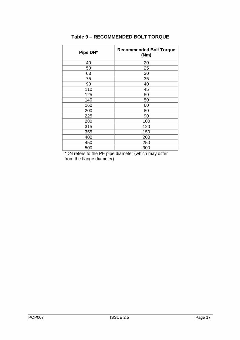
Table 9 – RECOMMENDED BOLT TORQUE
Pipe DN* Recommended Bolt Torque
(Nm)
40 20
50 25
63 30
75 35
90 40
110 45
125 50
140 50
160 60
200 80
225 90
280 100
315 120
355 150
400 200
450 250
500 300
*DN refers to the PE pipe diameter (which may differ
from the flange diameter)
POP007 ISSUE 2.5 Page 18
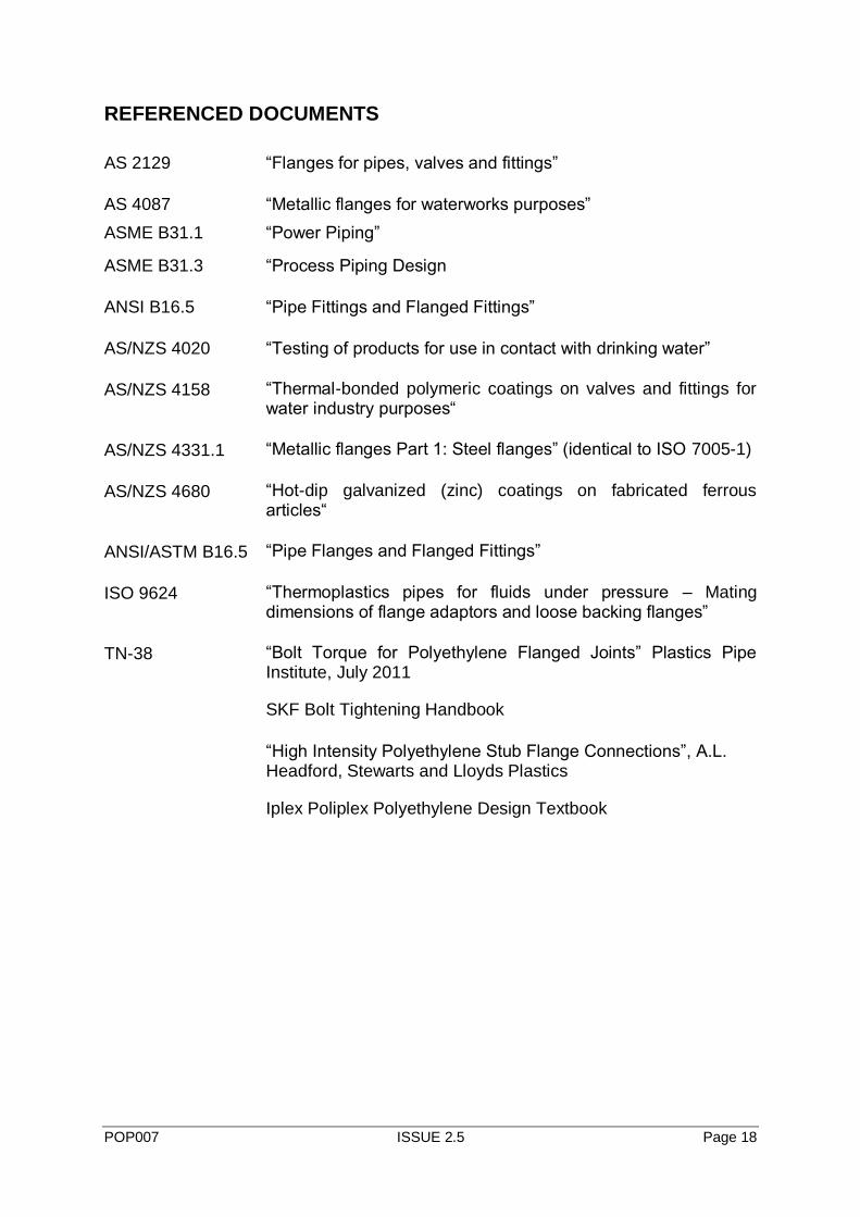
REFERENCED DOCUMENTS
AS 2129 “Flanges for pipes, valves and fittings”
AS 4087 “Metallic flanges for waterworks purposes”
ASME B31.1 “Power Piping”
ASME B31.3 “Process Piping Design
ANSI B16.5 “Pipe Fittings and Flanged Fittings”
AS/NZS 4020 “Testing of products for use in contact with drinking water”
AS/NZS 4158 “Thermal-bonded polymeric coatings on valves and fittings for water industry purposes“
AS/NZS 4331.1 “Metallic flanges Part 1: Steel flanges” (identical to ISO 7005-1)
AS/NZS 4680 “Hot-dip galvanized (zinc) coatings on fabricated ferrous articles“
ANSI/ASTM B16.5 “Pipe Flanges and Flanged Fittings”
ISO 9624 “Thermoplastics pipes for fluids under pressure – Mating dimensions of flange adaptors and loose backing flanges”
TN-38 “Bolt Torque for Polyethylene Flanged Joints” Plastics Pipe Institute, July 2011
SKF Bolt Tightening Handbook
“High Intensity Polyethylene Stub Flange Connections”, A.L. Headford, Stewarts and Lloyds Plastics
Iplex Poliplex Polyethylene Design Textbook