meso scale centrifugal compressor
TRANSCRIPT
1 Copyright © 2000 by ASME
Proceedings of IMECE:International Mechanical Engineering Congress & Exposition
November 5-10, 2000 Orlando, Florida
DESIGN, ANALYSIS AND FABRICATION OF A MESO-SCALE CENTRIFUGALCOMPRESSOR
A. Laveau, J. S. Kapat, L. C. Chow, E. EnikovDepartment of Mechanical, Materials & Aerospace Engineering
University of Central Florida
K. B. SundaramSchool of Electrical Engineering and Computer Science
University of Central Florida
ABSTRACTA gas or vapor compressor is one of the key components ofmany engineering systems, such as certain designs of vaporcompression refrigeration systems, cryo-coolers, air handlers.For meso-scale systems with linear dimensions of a fewcentimeters, conventional designs do not work efficientlybecause of rather large relative tolerances, and hence thesemeso-scale systems require micro-fabricated components forefficient operation. This paper presents a meso-scalecentrifugal compressor fabricated by photo-lithographictechniques.A preliminary design based on 1-D flow analysis using air asthe working fluid shows that a 50 mm diameter centrifugalcompressor with a blade height of 200 µm gives a staticpressure ratio of 1.12. In this design, the impeller has 10 fullblades and 10 splitter blades. Each blade has the NACA profile9510 with the maximum camber at 50% of the chord. Theseimpeller blades have exit angles 35o with exit flow angles of60o. A vaned diffuser having 20 equally spaced vanes with thesame NACA profile is used to improve compressor efficiency.A 3-D compressible, viscous flow analysis has been done usinga commercial finite volume software. The results of thisanalysis allowed the verification of the flow characteristicsinside the meso-scale centrifugal compressor.The compressor has been fabricated using micro-fabricationtechniques. The rotor and the stator are made by etching asilicon wafer by using DRIE (Deep Reactive Ion Etching)technique. A Pyrex wafer is then bonded to the stator for visualaccess inside the compressor.
INTRODUCTIONAdvances in micro-fabrication capabilities over the lastdecades have facilitated a new era in miniaturization ofengineering systems. Photolithography, thin-film depositionand anisotropic etching, the same techniques that have allowedthe electronics industry to pack more and more memory andcomputing power into smaller and smaller chips, can be usedto make compressors, pumps, valves, sensors, heat exchangersand chemical reactors at millimeter or smaller scales [1-2].Miniaturization of thermal and chemical systems offers severaladvantages over their large-scale counterparts. (1) Transportprocesses, both thermal and chemical, rely on surface area ofheat exchangers or reactors. Hence, the higher surface-to-volume ratios of a miniature system help to make morecompact systems with higher volumetric transport coefficients.(2) For meso-scale systems, micro-fabrication provides bettertolerances, leading to better performance. (3) Smaller sizetypically leads to better safety. (4) Use of micro-fabricationtechnology is expected to provide better cost efficiency. (5)Miniaturization makes newer engineering systems possible. (6)Smaller modular size leads to more options in usage.It is primarily the first two advantages that motivated thedevelopment of a meso-scale refrigerator. The two intendedapplications of this system are (1) an integrated heat removalsystem for electronics or photonic entities, and (2) an activelycooled jacket for personnel.The preliminary design requirements for the overall systemhave been set at [3-4] (1) evaporator temperature of 12 °C, (2)condenser exit temperature of 60 °C, (3) heat removal rate of350 W with refrigerant R134a, (4) saturated vapor at
2 Copyright © 2000 by ASME
compressor inlet and saturated liquid at condenser exit.Conceptual design of the complete refrigerator has led to acylindrical shape made of multiple layers. Furthermore, it hasbeen decided that the compressor would be fabricated byreadily available micro- fabrication techniques. As a result,three-dimensional features such as curved inducer blades havenot been considered in this preliminary design. Because ofdesign consideration for the air-side heat rejection heatexchanger as well as available photo-lithographic equipment,the outside diameter of the cylindrical shaped refrigerator wasset at 63.5 mm (2.5 inches).The viability of the meso-scale refrigerator has already beenstudied [4]. It is now necessary to consider each component ofthe refrigerator, particularly the compressor, in more detail. Ithas been shown that the refrigerant cycle using R134a as theworking fluid needs a high increase in static pressure at a verylow mass flow rate.There are several different compressor designs that arecommonly used in conventional macro-scale systems, such as(1) centrifugal, (2) reciprocating, (3) screw-type and (4)sliding vane compressors. It has been presented earlier [4] thatbecause of structural restrictions imposed by available micro-fabrication techniques, screw-type and sliding vane designs arenot considered at this time. Preliminary design calculationsindicate that a meso-scale, micro-fabricated reciprocatingdesign may not be desirable for the current application for oneor more of the following several reasons depending on actualdesign configuration [5]. (1) Flow leakage past the piston andsliding friction between piston and chamber can be significant.(2) Several micro-units are needed to provide the needed flowrate. (3) More complicated micro-fabrication is needed, thuspossibly leading to lower reliability. Thus, centrifugal designappears to be the first choice for a meso-scale compressor andis the focus of this paper, which presents the preliminarydesign of a meso-scale centrifugal compressor that may beused in a meso-scale vapor compression refrigerator.Preliminary design for R134a compression will be presentedfirst. The objective of this process is to design a centrifugalcompressor that can be used as a part of the meso-scalerefrigerator system. However, complete design, testing andperformance prediction for R134a is quite involved sinceR134a cannot be treated as an ideal gas and test set-up is morecomplicated. Hence, in order to quickly determine thefeasibility of a micro-fabricated, meso-scale compressor, therest of the paper will concentrate on air compression, wherethe design for R134a compression will be used with minimalmodification.
NOMENCLATUREa speed of sound (m/s)b blade height (m)c absolute velocity (m/s)
Cp air specific heat (J/kg.K)D diameter (m)h enthalpy (J)l mean free path (m)M Mach numbermf mass flow rate (kg/s)N rotational speed (rpm)p pressure (Pa)Pf frictional power loss (W)Pw output power (W)R gas constant (J/kg.K)rs static pressure ratioT temperature (°C)U peripheral velocity (m/s)w relative velocity in rotational frame (m/s)∆W specific work (J)Z number of impeller bladesα flow angle (°)β blade angle (°)γ specific heat ratioη stagnation to stagnation overall efficiencyµ air dynamic viscosity (Pa.s)ρ air density (kg/m3)σ slip factorτ torque (N.m)ω rotational speed (rad/s)ψ loading coefficient
Subscripts0 stagnation1 eye of the compressor2 impeller exit of the compressor3 diffuser exit of the compressorac actualiss isentropic (Figure 2)r radial directionth theoretical valuex axial directionθ tangential direction
PRELIMINARY ANALYSIS FOR R134aThe preliminary design of the meso-scale centrifugalcompressor is done using a 1-dimensional flow and
3 Copyright © 2000 by ASME
thermodynamic analysis, which allows computation ofdifferent compressor characteristics such as the static pressureratio [6-8].First, it is necessary to verify if conventional large scalecentrifugal compressor design techniques can be applied to ameso-scale design. This is done by analyzing the value of themean free path between molecules of the fluid [9].
The mean free path is defined as
l ≈ a67.0 ⋅⋅ρ
µ (1)
The refrigerant properties at the inlet of the compressor arefixed by the cycle and are defined by a static pressure, p1 =4.41 bar and a static temperature, T1 = 12 °C. Allthermodynamic and transport properties of R134a aredetermined using a software called REFPROP [10], as R134acannot be considered as an ideal gas. These conditions give aviscosity µ = 11.23⋅10-6 Pa.s, a density ρ = 21.48 kg/m3 and aspeed of sound a = 146.2 m/s. The mean free path at the inletof the compressor is then l = 5.33 nm, which is the highestmean free path value that is encountered in the compressor.The smallest blade height that was considered is 10 µm, whichis about 1900 times bigger than the mean free path betweenR134a molecules.Therefore, conventional large scale centrifugal compressordesign techniques can be applied to the meso-scale centrifugalcompressor design presented here.The mass flow rate is determined from the refrigerant cycleand is mf = 0.00333kg/s.The choice of diameter D3 (Fig. 1) has been guided by theoverall diameter of the meso-scale refrigerator. Diameter D2
has been chosen so that the ratio D2/D3 is similar to that for aconventional vaned centrifugal compressor. Diameter D1 ischosen so that the diameter is neither too big to reduceimpeller performance nor too small to cause a large inletvelocity and hence large dynamic head.It is assumed that there is no swirl at the inlet of thecompressor, indicating that the flow is axial with an absolutevelocity of cx1 as it enters the eye of the compressor. As theflow turns and enters the impeller, the flow will have asignificant radial component, but no tangential component ininertial reference frame. However, the flow will have atangential component in the rotational frame, and hence theblade inlet angle is set equal to the relative flow angle at thatpoint.The number of blades Z has been determined so that highblockage and high blade loading risks are avoided. The samenumber of blades with the same profile is used for both theimpeller and the diffuser. Backswept blades, which have apositive blade angle compared to the radial direction (β2 > 0°),are chosen here because they give a reduction of the impellerexit Mach number, M2, at any given tip speed and limit the
risk of shock in the impeller, even though they reduce thecompressor pressure ratio. Finally, the theoretical flow angle atimpeller exit, α2, is set at 60o as several researchers [11] haveshown that the optimum flow angle for backswept vanes is inthe range 60° < α2 < 70°. In general, the overall efficiency isobtained through detailed flow calculation or experiments.However, for the thermodynamic calculation, a value isneeded, and hence an ad-hoc value of 0.78 was chosen for thestagnation to stagnation overall efficiency for the wholecompressor. All the assumptions made are summarized in thefollowing table.
D1(mm)
D2(mm)
D3(mm)
Z η α2(°)
3 20 50 20 0.78 60
Table 1. Input data with R134a as the working fluid
The analysis that is outlined below also required values forblade height, b, and rotational speed, N as inputs. Severalvalues between 10 µm and 200 µm were tried for b. The valueof N is limited by the specifications of the meso-scale motor,which is being designed concurrently. In this analysis, only100,000 rpm and slower values were used for N.
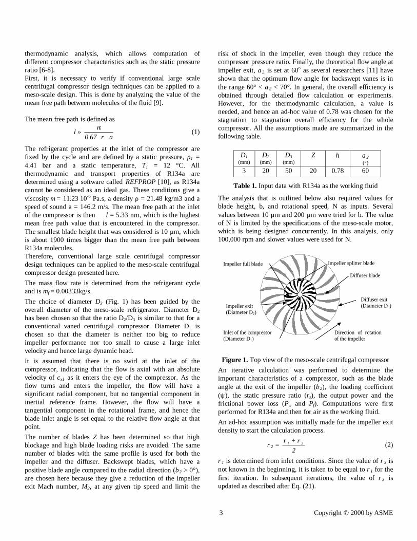
Figure 1. Top view of the meso-scale centrifugal compressorAn iterative calculation was performed to determine theimportant characteristics of a compressor, such as the bladeangle at the exit of the impeller (β2), the loading coefficient(ψ ), the static pressure ratio (rs), the output power and thefrictional power loss (Pw and Pf). Computations were firstperformed for R134a and then for air as the working fluid.An ad-hoc assumption was initially made for the impeller exitdensity to start the calculation process.
ρ2 = 2
31 ρ+ρ (2)
ρ1 is determined from inlet conditions. Since the value of ρ3 isnot known in the beginning, it is taken to be equal to ρ1 for thefirst iteration. In subsequent iterations, the value of ρ3 isupdated as described after Eq. (21).
Diffuser blade
Impeller full blade Impeller splitter blade
Inlet of the compressor(Diameter D1)
Direction of rotationof the impeller
Impeller exit(Diameter D2)
Diffuser exit(Diameter D3)
4 Copyright © 2000 by ASME
The radial absolute velocity at the impeller exit is given by
cr2 =bD
m
22
f
⋅⋅⋅ρπ(3)
The theoretical tangential absolute velocity at the impeller exitis then given by
cθ2,th = )tan(c 22r α⋅ (4)
and the blade angle β2 is then calculated from the velocitytriangle.
β2 = atan
−
2r
th,2
ccU θ2 (5)
with U2 = ?2
D2 ⋅ and ω = 60N
p2 ⋅ (6)
In reality, slip takes place in the impeller and changes thevalue of the tangential absolute velocity at the impeller exitfrom the its theoretical value. Different semi-theoreticalrelations are available in literature for slip factor that isdefined as the ratio of the actual to theoretical values of thetangential absolute velocity, that is,
cθ2 = s⋅th,cθ2 (7)
In this analysis, the correlation of Wiesner [12] has been usedwhere
σ = 1 - Z 7.0
)cos( 2β (8)
Here the slip factor is first calculated from Eq. (8), and then isthe tangential absolute velocity from Eq. (7).Finally, assuming that the axial absolute velocity at the exit ofthe impeller cx2 is negligible compared to the other velocitycomponents, the absolute velocity at the exit of the impeller iscalculated as
c2 = θ2cc 22r
2 + (9)
The actual flow angle is then calculated as
=
2rac,2 c
ctana θ2α (10)
It is now possible to calculate the specific work ∆W and theloading coefficient ψ of the compressor. This coefficient is animportant characteristic because it allows comparing theabsolute flow tangential velocity at the exit of the impeller cθ2
to the blade peripheral velocity U2.∆W = 2θ2 Uc ⋅ (11)
ψ = 22UW∆
= 2U
cθ2 (12)
Enthalpy, h1, is then determined with REFPROP using theinlet pressure and temperature as input data, and the totalenthalpy at the impeller exit is computed.
h02 = ∆W + h01 (13)
with h01 = h1 + 21xc5.0 ⋅ (14)
and cx1 = 1
21 Dm4 f
⋅⋅⋅ρπ
(15)
The stagnation enthalpy h0 is conserved in the diffuser, asthere is no work applied to the fluid. The stagnation enthalpyat the exit of the impeller h02 is therefore equal to thestagnation enthalpy at the exit of the diffuser h03. The ad-hocassumption about the total-to-total compressor efficiency helpsthen to compute the isentropic stagnation enthalpy at the exitof the diffuser iss,03h .
( ) 010103iss03 hhhh +−⋅=η (16)
with 01h defined as in equation (14).
From definitions of stagnation state and isentropic process,entropy in state 03 iss (Fig. 2) is then calculated as
s03iss = s01 = s1 (17)where s1 is computed with REFPROP.
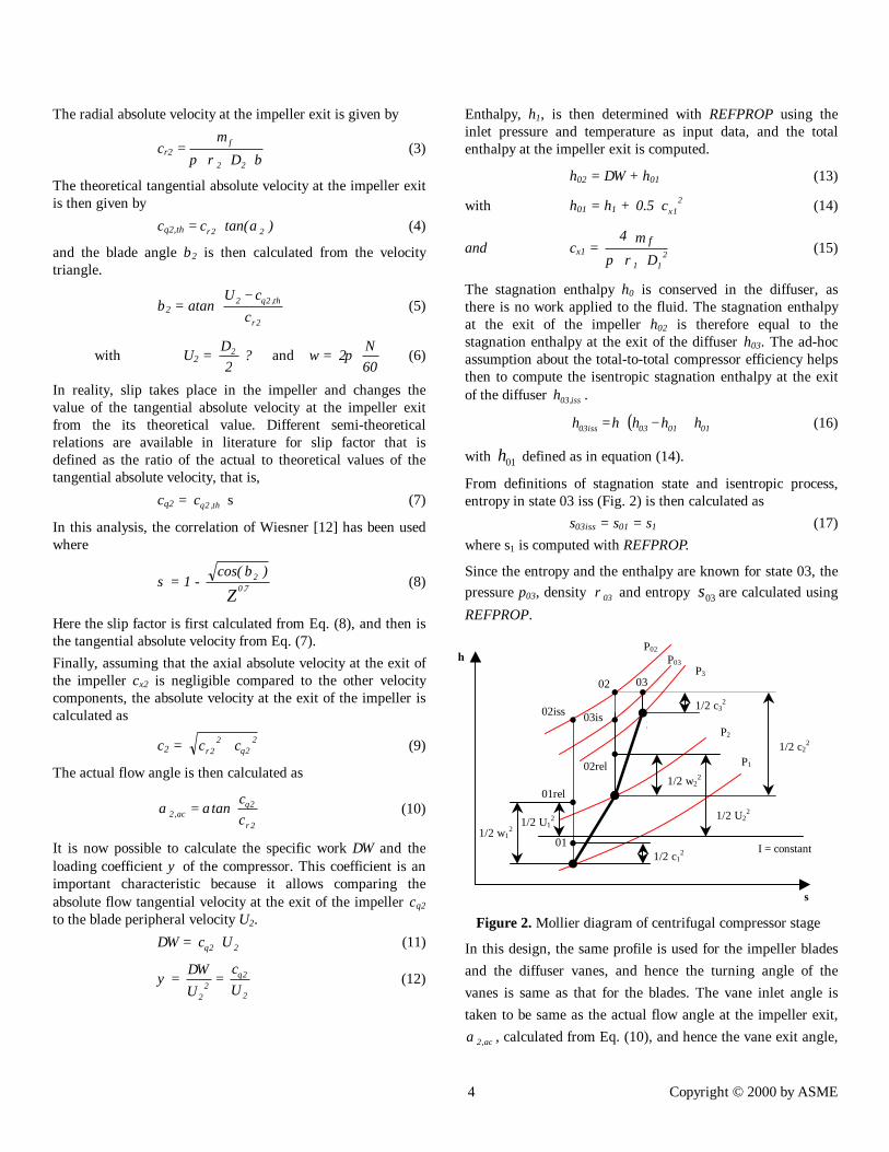
Since the entropy and the enthalpy are known for state 03, thepressure p03, density 03ρ and entropy 03s are calculated usingREFPROP.
Figure 2. Mollier diagram of centrifugal compressor stage
In this design, the same profile is used for the impeller bladesand the diffuser vanes, and hence the turning angle of thevanes is same as that for the blades. The vane inlet angle istaken to be same as the actual flow angle at the impeller exit,
ac,2α , calculated from Eq. (10), and hence the vane exit angle,
I = constant
1/2⋅c22
1/2⋅w12
1
2
3
03
03is02iss 1/2⋅c32
1/2⋅w22
1/2⋅U22
1/2⋅c12
1/2⋅U12
01
01rel
02rel
h
s
P02
P03P3
02
P2
P1
5 Copyright © 2000 by ASME
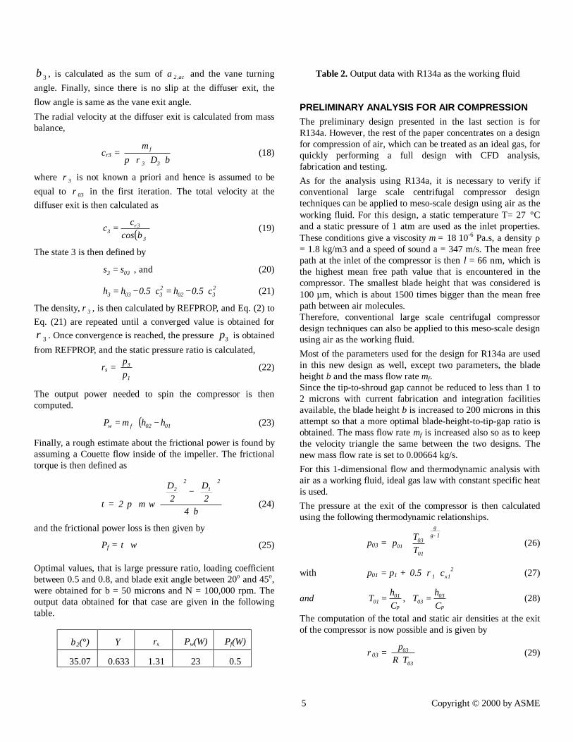
3β , is calculated as the sum of ac,2α and the vane turningangle. Finally, since there is no slip at the diffuser exit, theflow angle is same as the vane exit angle.The radial velocity at the diffuser exit is calculated from massbalance,
cr3 = bD
m
33
f
⋅⋅⋅ρπ (18)
where 3ρ is not known a priori and hence is assumed to beequal to 03ρ in the first iteration. The total velocity at thediffuser exit is then calculated as
( )3
3r3 cos
cc
β= (19)
The state 3 is then defined by
033 ss = , and (20)
2302
23033 c5.0hc5.0hh ⋅−=⋅−= (21)
The density, 3ρ , is then calculated by REFPROP, and Eq. (2) toEq. (21) are repeated until a converged value is obtained for
3ρ . Once convergence is reached, the pressure 3p is obtainedfrom REFPROP, and the static pressure ratio is calculated,
rs = 1
3
pp
(22)
The output power needed to spin the compressor is thencomputed.
( )0102fw hhmP −⋅= (23)
Finally, a rough estimate about the frictional power is found byassuming a Couette flow inside of the impeller. The frictionaltorque is then defined as
τ = b4
2D
2D
2
21
22
⋅
−
⋅⋅⋅⋅ ωµπ (24)
and the frictional power loss is then given by
Pf = ωτ ⋅ (25)
Optimal values, that is large pressure ratio, loading coefficientbetween 0.5 and 0.8, and blade exit angle between 20o and 45o,were obtained for b = 50 microns and N = 100,000 rpm. Theoutput data obtained for that case are given in the followingtable.
β2(°) Ψ rs Pw(W) Pf(W)
35.07 0.633 1.31 23 0.5
Table 2. Output data with R134a as the working fluid
PRELIMINARY ANALYSIS FOR AIR COMPRESSIONThe preliminary design presented in the last section is forR134a. However, the rest of the paper concentrates on a designfor compression of air, which can be treated as an ideal gas, forquickly performing a full design with CFD analysis,fabrication and testing.As for the analysis using R134a, it is necessary to verify ifconventional large scale centrifugal compressor designtechniques can be applied to meso-scale design using air as theworking fluid. For this design, a static temperature T= 27 °Cand a static pressure of 1 atm are used as the inlet properties.These conditions give a viscosity µ = 18⋅10-6 Pa.s, a density ρ= 1.8 kg/m3 and a speed of sound a = 347 m/s. The mean freepath at the inlet of the compressor is then l = 66 nm, which isthe highest mean free path value that is encountered in thecompressor. The smallest blade height that was considered is100 µm, which is about 1500 times bigger than the mean freepath between air molecules.Therefore, conventional large scale centrifugal compressordesign techniques can also be applied to this meso-scale designusing air as the working fluid.Most of the parameters used for the design for R134a are usedin this new design as well, except two parameters, the bladeheight b and the mass flow rate mf.Since the tip-to-shroud gap cannot be reduced to less than 1 to2 microns with current fabrication and integration facilitiesavailable, the blade height b is increased to 200 microns in thisattempt so that a more optimal blade-height-to-tip-gap ratio isobtained. The mass flow rate mf is increased also so as to keepthe velocity triangle the same between the two designs. Thenew mass flow rate is set to 0.00664 kg/s.For this 1-dimensional flow and thermodynamic analysis withair as a working fluid, ideal gas law with constant specific heatis used.The pressure at the exit of the compressor is then calculatedusing the following thermodynamic relationships.
p03 = 1−γ
γ
⋅
01
0301 T
Tp (26)
with p01 = p1 + 21x1 c5.0 ⋅⋅ρ (27)
andp
0303
p
0101 C
hT,ChT == (28)
The computation of the total and static air densities at the exitof the compressor is now possible and is given by
ρ03 = 03
03
TRp⋅
(29)
6 Copyright © 2000 by ASME
M3 = 03
3r
TRc
⋅⋅γ(30)
ρ3 =
1
3
2
03 2
M)(1
−
⋅+⋅
γ
1−γρ (31)
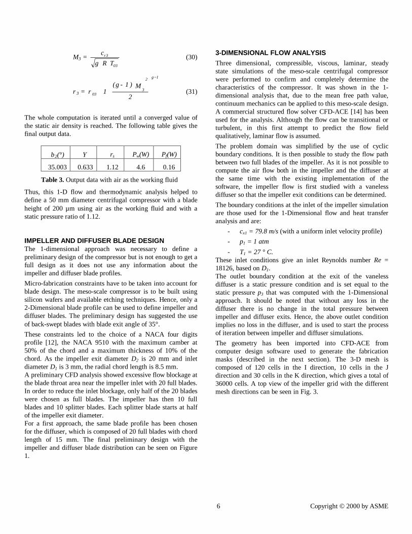
The whole computation is iterated until a converged value ofthe static air density is reached. The following table gives thefinal output data.
β2(°) Ψ rs Pw(W) Pf(W)
35.003 0.633 1.12 4.6 0.16
Table 3. Output data with air as the working fluid
Thus, this 1-D flow and thermodynamic analysis helped todefine a 50 mm diameter centrifugal compressor with a bladeheight of 200 µm using air as the working fluid and with astatic pressure ratio of 1.12.
IMPELLER AND DIFFUSER BLADE DESIGNThe 1-dimensional approach was necessary to define apreliminary design of the compressor but is not enough to get afull design as it does not use any information about theimpeller and diffuser blade profiles.Micro-fabrication constraints have to be taken into account forblade design. The meso-scale compressor is to be built usingsilicon wafers and available etching techniques. Hence, only a2-Dimensional blade profile can be used to define impeller anddiffuser blades. The preliminary design has suggested the useof back-swept blades with blade exit angle of 35°.These constraints led to the choice of a NACA four digitsprofile [12], the NACA 9510 with the maximum camber at50% of the chord and a maximum thickness of 10% of thechord. As the impeller exit diameter D2 is 20 mm and inletdiameter D1 is 3 mm, the radial chord length is 8.5 mm.A preliminary CFD analysis showed excessive flow blockage atthe blade throat area near the impeller inlet with 20 full blades.In order to reduce the inlet blockage, only half of the 20 bladeswere chosen as full blades. The impeller has then 10 fullblades and 10 splitter blades. Each splitter blade starts at halfof the impeller exit diameter.For a first approach, the same blade profile has been chosenfor the diffuser, which is composed of 20 full blades with chordlength of 15 mm. The final preliminary design with theimpeller and diffuser blade distribution can be seen on Figure1.
3-DIMENSIONAL FLOW ANALYSISThree dimensional, compressible, viscous, laminar, steadystate simulations of the meso-scale centrifugal compressorwere performed to confirm and completely determine thecharacteristics of the compressor. It was shown in the 1-dimensional analysis that, due to the mean free path value,continuum mechanics can be applied to this meso-scale design.A commercial structured flow solver CFD-ACE [14] has beenused for the analysis. Although the flow can be transitional orturbulent, in this first attempt to predict the flow fieldqualitatively, laminar flow is assumed.The problem domain was simplified by the use of cyclicboundary conditions. It is then possible to study the flow pathbetween two full blades of the impeller. As it is not possible tocompute the air flow both in the impeller and the diffuser atthe same time with the existing implementation of thesoftware, the impeller flow is first studied with a vanelessdiffuser so that the impeller exit conditions can be determined.The boundary conditions at the inlet of the impeller simulationare those used for the 1-Dimensional flow and heat transferanalysis and are:
- cx1 = 79.8 m/s (with a uniform inlet velocity profile)- p1 = 1 atm- T1 = 27 ° C.
These inlet conditions give an inlet Reynolds number Re =18126, based on D1.The outlet boundary condition at the exit of the vanelessdiffuser is a static pressure condition and is set equal to thestatic pressure p3 that was computed with the 1-Dimensionalapproach. It should be noted that without any loss in thediffuser there is no change in the total pressure betweenimpeller and diffuser exits. Hence, the above outlet conditionimplies no loss in the diffuser, and is used to start the processof iteration between impeller and diffuser simulations.The geometry has been imported into CFD-ACE fromcomputer design software used to generate the fabricationmasks (described in the next section). The 3-D mesh iscomposed of 120 cells in the I direction, 10 cells in the Jdirection and 30 cells in the K direction, which gives a total of36000 cells. A top view of the impeller grid with the differentmesh directions can be seen in Fig. 3.
7 Copyright © 2000 by ASME
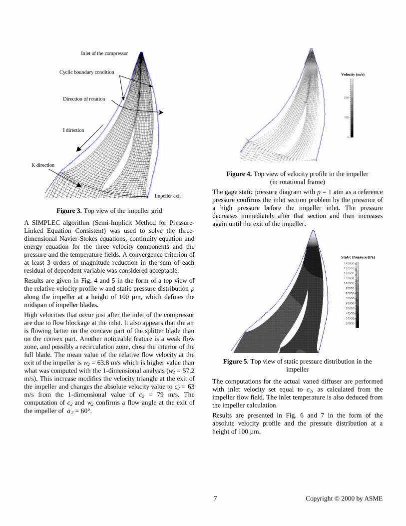
Figure 3. Top view of the impeller grid
A SIMPLEC algorithm (Semi-Implicit Method for Pressure-Linked Equation Consistent) was used to solve the three-dimensional Navier-Stokes equations, continuity equation andenergy equation for the three velocity components and thepressure and the temperature fields. A convergence criterion ofat least 3 orders of magnitude reduction in the sum of eachresidual of dependent variable was considered acceptable.Results are given in Fig. 4 and 5 in the form of a top view ofthe relative velocity profile w and static pressure distribution palong the impeller at a height of 100 µm, which defines themidspan of impeller blades.High velocities that occur just after the inlet of the compressorare due to flow blockage at the inlet. It also appears that the airis flowing better on the concave part of the splitter blade thanon the convex part. Another noticeable feature is a weak flowzone, and possibly a recirculation zone, close the interior of thefull blade. The mean value of the relative flow velocity at theexit of the impeller is w2 = 63.8 m/s which is higher value thanwhat was computed with the 1-dimensional analysis (w2 = 57.2m/s). This increase modifies the velocity triangle at the exit ofthe impeller and changes the absolute velocity value to c2 = 63m/s from the 1-dimensional value of c2 = 79 m/s. Thecomputation of c2 and w2 confirms a flow angle at the exit ofthe impeller of α2 = 60°.
Figure 4. Top view of velocity profile in the impeller(in rotational frame)
The gage static pressure diagram with p = 1 atm as a referencepressure confirms the inlet section problem by the presence ofa high pressure before the impeller inlet. The pressuredecreases immediately after that section and then increasesagain until the exit of the impeller.
Figure 5. Top view of static pressure distribution in theimpeller
The computations for the actual vaned diffuser are performedwith inlet velocity set equal to c2, as calculated from theimpeller flow field. The inlet temperature is also deduced fromthe impeller calculation.Results are presented in Fig. 6 and 7 in the form of theabsolute velocity profile and the pressure distribution at aheight of 100 µm.
K direction
Cyclic boundary condition
I direction
Inlet of the compressor
Impeller exit
Direction of rotation
Velocity (m/s)
Static Pressure (Pa)
8 Copyright © 2000 by ASME
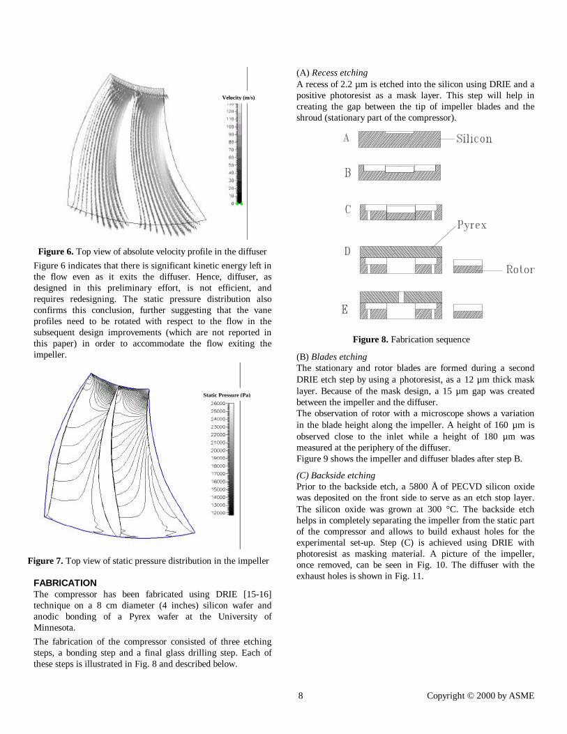
Figure 6. Top view of absolute velocity profile in the diffuserFigure 6 indicates that there is significant kinetic energy left inthe flow even as it exits the diffuser. Hence, diffuser, asdesigned in this preliminary effort, is not efficient, andrequires redesigning. The static pressure distribution alsoconfirms this conclusion, further suggesting that the vaneprofiles need to be rotated with respect to the flow in thesubsequent design improvements (which are not reported inthis paper) in order to accommodate the flow exiting theimpeller.
Figure 7. Top view of static pressure distribution in the impeller
FABRICATIONThe compressor has been fabricated using DRIE [15-16]technique on a 8 cm diameter (4 inches) silicon wafer andanodic bonding of a Pyrex wafer at the University ofMinnesota.The fabrication of the compressor consisted of three etchingsteps, a bonding step and a final glass drilling step. Each ofthese steps is illustrated in Fig. 8 and described below.
(A) Recess etchingA recess of 2.2 µm is etched into the silicon using DRIE and apositive photoresist as a mask layer. This step will help increating the gap between the tip of impeller blades and theshroud (stationary part of the compressor).
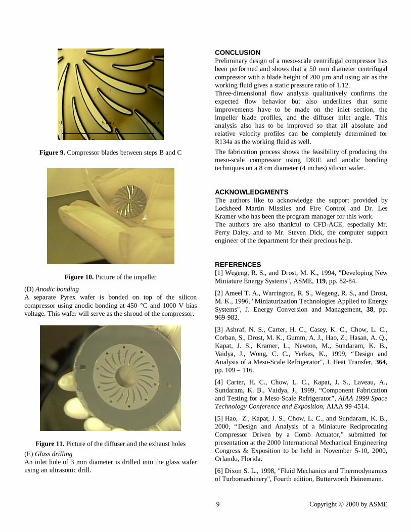
(B) Blades etchingThe stationary and rotor blades are formed during a secondDRIE etch step by using a photoresist, as a 12 µm thick masklayer. Because of the mask design, a 15 µm gap was createdbetween the impeller and the diffuser.The observation of rotor with a microscope shows a variationin the blade height along the impeller. A height of 160 µm isobserved close to the inlet while a height of 180 µm wasmeasured at the periphery of the diffuser.Figure 9 shows the impeller and diffuser blades after step B.
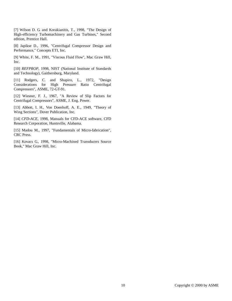
(C) Backside etchingPrior to the backside etch, a 5800 Å of PECVD silicon oxidewas deposited on the front side to serve as an etch stop layer.The silicon oxide was grown at 300 °C. The backside etchhelps in completely separating the impeller from the static partof the compressor and allows to build exhaust holes for theexperimental set-up. Step (C) is achieved using DRIE withphotoresist as masking material. A picture of the impeller,once removed, can be seen in Fig. 10. The diffuser with theexhaust holes is shown in Fig. 11.
Figure 8. Fabrication sequence
Velocity (m/s)
Static Pressure (Pa)
9 Copyright © 2000 by ASME
Figure 9. Compressor blades between steps B and C
Figure 10. Picture of the impeller
(D) Anodic bondingA separate Pyrex wafer is bonded on top of the siliconcompressor using anodic bonding at 450 °C and 1000 V biasvoltage. This wafer will serve as the shroud of the compressor.
Figure 11. Picture of the diffuser and the exhaust holes(E) Glass drillingAn inlet hole of 3 mm diameter is drilled into the glass waferusing an ultrasonic drill.
CONCLUSIONPreliminary design of a meso-scale centrifugal compressor hasbeen performed and shows that a 50 mm diameter centrifugalcompressor with a blade height of 200 µm and using air as theworking fluid gives a static pressure ratio of 1.12.Three-dimensional flow analysis qualitatively confirms theexpected flow behavior but also underlines that someimprovements have to be made on the inlet section, theimpeller blade profiles, and the diffuser inlet angle. Thisanalysis also has to be improved so that all absolute andrelative velocity profiles can be completely determined forR134a as the working fluid as well.The fabrication process shows the feasibility of producing themeso-scale compressor using DRIE and anodic bondingtechniques on a 8 cm diameter (4 inches) silicon wafer.
ACKNOWLEDGMENTSThe authors like to acknowledge the support provided byLockheed Martin Missiles and Fire Control and Dr. LesKramer who has been the program manager for this work.The authors are also thankful to CFD-ACE, especially Mr.Perry Daley, and to Mr. Steven Dick, the computer supportengineer of the department for their precious help.
REFERENCES[1] Wegeng, R. S., and Drost, M. K., 1994, "Developing NewMiniature Energy Systems", ASME, 119, pp. 82-84.
[2] Ameel T. A., Warrington, R. S., Wegeng, R. S., and Drost,M. K., 1996, "Miniaturization Technologies Applied to EnergySystems", J. Energy Conversion and Management, 38, pp.969-982.
[3] Ashraf, N. S., Carter, H. C., Casey, K. C., Chow, L. C.,Corban, S., Drost, M. K., Gumm, A. J., Hao, Z., Hasan, A. Q.,Kapat, J. S., Kramer, L., Newton, M., Sundaram, K. B.,Vaidya, J., Wong, C. C., Yerkes, K., 1999, “Design andAnalysis of a Meso-Scale Refrigerator", J. Heat Transfer, 364,pp. 109 – 116.
[4] Carter, H. C., Chow, L. C., Kapat, J. S., Laveau, A.,Sundaram, K. B., Vaidya, J., 1999, “Component Fabricationand Testing for a Meso-Scale Refrigerator”, AIAA 1999 SpaceTechnology Conference and Exposition, AIAA 99-4514.
[5] Hao, Z., Kapat, J. S., Chow, L. C., and Sundaram, K. B.,2000, “Design and Analysis of a Miniature ReciprocatingCompressor Driven by a Comb Actuator,” submitted forpresentation at the 2000 International Mechanical EngineeringCongress & Exposition to be held in November 5-10, 2000,Orlando, Florida.
[6] Dixon S. L., 1998, "Fluid Mechanics and Thermodynamicsof Turbomachinery", Fourth edition, Butterworth Heinemann.
0 5 mm 10 mm
10 Copyright © 2000 by ASME
[7] Wilson D. G. and Korakianitis, T., 1998, "The Design ofHigh-efficiency Turbomachinery and Gas Turbines," Secondedition, Prentice Hall.
[8] Japikse D., 1996, "Centrifugal Compressor Design andPerformance," Concepts ETI, Inc.
[9] White, F. M., 1991, "Viscous Fluid Flow", Mac Graw Hill,Inc.
[10] REFPROP, 1998, NIST (National Institute of Standardsand Technology), Gaithersburg, Maryland.
[11] Rodgers, C. and Shapiro, L., 1972, "DesignConsiderations for High Pressure Ratio CentrifugalCompressors", ASME, 72-GT-91.
[12] Wiesner, F. J., 1967, "A Review of Slip Factors forCentrifugal Compressors", ASME, J. Eng. Power.
[13] Abbott, I. H., Von Doenhoff, A. E., 1949, "Theory ofWing Sections", Dover Publication, Inc.
[14] CFD-ACE, 1998, Manuals for CFD-ACE software, CFDResearch Corporation, Huntsville, Alabama.
[15] Madou M., 1997, "Fundamentals of Micro-fabrication",CRC Press.
[16] Kovacs G., 1998, "Micro-Machined Transducers SourceBook," Mac Graw Hill, Inc.