menus interface user’s guide · 613-50570-00 rev. b management software at-s63 menus interface...
TRANSCRIPT
613-50570-00 Rev. B
Management Software
AT-S63
Menus InterfaceUser’s GuideAT-9400 Series Layer 2+ Gigabit Ethernet Switches
Version 1.1.0

Copyright © 2005 Allied Telesyn, Inc. All rights reserved. No part of this publication may be reproduced without prior written permission from Allied Telesyn, Inc.Microsoft and Internet Explorer are registered trademarks of Microsoft Corporation. Netscape Navigator is a registered trademark of Netscape Communications Corporation. All other product names, company names, logos or other designations mentioned herein are trademarks or registered trademarks of their respective owners.Allied Telesyn, Inc. reserves the right to make changes in specifications and other information contained in this document without prior written notice. The information provided herein is subject to change without notice. In no event shall Allied Telesyn, Inc. be liable for any incidental, special, indirect, or consequential damages whatsoever, including but not limited to lost profits, arising out of or related to this manual or the information contained herein, even if Allied Telesyn, Inc. has been advised of, known, or should have known, the possibility of such damages.
Contents
Preface ............................................................................................................................................................ 23How This Guide is Organized........................................................................................................................... 24Where to Find Web-based Guides ................................................................................................................... 25Contacting Allied Telesyn ................................................................................................................................. 26
Online Support ........................................................................................................................................... 26Email and Telephone Support.................................................................................................................... 26Returning Products .................................................................................................................................... 26Sales or Corporate Information .................................................................................................................. 26Management Software Updates................................................................................................................. 26
Chapter 1: Overview ...................................................................................................................................... 27Management Overview..................................................................................................................................... 28Local Connection.............................................................................................................................................. 30Remote Connection.......................................................................................................................................... 31
Using an SNMP Network Management Application................................................................................... 31Management Access Levels............................................................................................................................. 33
Section I: Basic Operations ...................................................................................... 35Chapter 2: Starting a Management Session ............................................................................................... 37Starting a Local Management Session............................................................................................................. 38
Starting a Local Management Session ...................................................................................................... 38Quitting a Local Management Session ...................................................................................................... 40
Starting a Remote Management Session......................................................................................................... 41Starting a Remote Management Session .................................................................................................. 41Quitting a Remote Management Session .................................................................................................. 42
Chapter 3: Basic Switch Parameters ........................................................................................................... 43When Does a Switch Need an IP Address? ..................................................................................................... 44
How Do You Assign an IP Address?.......................................................................................................... 45Configuring the IP Address, Switch Name, and Other Basic Parameters ........................................................ 46Activating the BOOTP or DHCP Client Software.............................................................................................. 49Displaying the AT-9400 Series Switch Hardware and Software Information.................................................... 51Rebooting a Switch........................................................................................................................................... 53Working With the Manager and Operator Passwords ...................................................................................... 55
Changing the Manager or Operator Password .......................................................................................... 55Resetting the Manager Password .............................................................................................................. 57
Setting the System Time .................................................................................................................................. 58Setting the System Time Manually............................................................................................................. 58Setting the System Time from an SNTP or NTP Server ............................................................................ 59
Configuring the Console Startup Mode ............................................................................................................ 62Configuring the Console Timer......................................................................................................................... 63Enabling or Disabling the Telnet Server ........................................................................................................... 64Setting the Baud Rate of the Serial Terminal Port............................................................................................ 65Pinging a Remote System ................................................................................................................................ 66Returning the AT-S63 Management Software to the Factory Default Values .................................................. 67
3

Contents
Displaying System Hardware Information.........................................................................................................69Displaying Uplink Port Information....................................................................................................................71
Chapter 4: SNMPv1 and SNMPv2c ...............................................................................................................75SNMPv1 and SNMPv2c Overview....................................................................................................................76
Default SNMP Community Strings .............................................................................................................78Enabling or Disabling SNMP Management.......................................................................................................79Setting the Authentication Failure Trap.............................................................................................................80Creating an SNMP Community String ..............................................................................................................81Modifying a Community String ..........................................................................................................................84Displaying the SNMP Community Strings.........................................................................................................88
Chapter 5: Enhanced Stacking .....................................................................................................................89Enhanced Stacking Overview ...........................................................................................................................90
Enhanced Stacking Guidelines...................................................................................................................90Setting a Switch’s Enhanced Stacking Status ..................................................................................................93Selecting a Switch in an Enhanced Stack.........................................................................................................95Returning to the Master Switch.........................................................................................................................98Displaying the Enhanced Stacking Status ........................................................................................................99
Chapter 6: Port Parameters ........................................................................................................................101Configuring Port Parameters ..........................................................................................................................102Configuring Head of Line Blocking..................................................................................................................107Configuring Flow Control and Back Pressure .................................................................................................109Configuring Filtering........................................................................................................................................112Setting Up Rate Limiting .................................................................................................................................114Resetting a Port ..............................................................................................................................................116Forcing Port Renegotiation .............................................................................................................................117Resetting the Port Configuration to the Defaults.............................................................................................118Displaying Port Statistics ................................................................................................................................119Clearing Port Statistics....................................................................................................................................122Displaying Port Status.....................................................................................................................................123
Chapter 7: Static and LACP Port Trunks ...................................................................................................125Port Trunk Overview .......................................................................................................................................126
Static Port Trunk Overview.......................................................................................................................126LACP Trunk Overview ..............................................................................................................................128Load Distribution Methods........................................................................................................................134
Managing Static Port Trunks...........................................................................................................................136Creating a Static Port Trunk .....................................................................................................................136Modifying a Static Port Trunk ...................................................................................................................139Deleting a Static Port Trunk......................................................................................................................141
Managing LACP Trunks..................................................................................................................................143Enabling or Disabling LACP .....................................................................................................................143Setting a LACP System Priority................................................................................................................144Creating an Aggregator ............................................................................................................................145Modifying an Aggregator ..........................................................................................................................147Deleting an Aggregator.............................................................................................................................149Configuring LACP Port Parameters..........................................................................................................150Displaying LACP Port or Aggregator Status.............................................................................................151
Chapter 8: Port Mirroring ............................................................................................................................155Port Mirroring Overview ..................................................................................................................................156Creating a Port Mirror .....................................................................................................................................157Disabling a Port Mirror ....................................................................................................................................159Modifying a Port Mirror....................................................................................................................................160Displaying the Port Mirror ...............................................................................................................................161
4
AT-S63 Management Software Menus Interface User’s Guide
Chapter 9: Networking Stack ...................................................................................................................... 163Managing the Address Resolution Protocol (ARP) Table............................................................................... 164
Displaying the ARP Table ........................................................................................................................ 165Deleting an ARP Table Entry ................................................................................................................... 166Resetting the ARP Table.......................................................................................................................... 167Setting the ARP Cache Timeout .............................................................................................................. 168
Displaying the Route Table ............................................................................................................................ 169Displaying the TCP Connections.................................................................................................................... 171Deleting a TCP Connection ............................................................................................................................ 174Displaying the TCP Global Information .......................................................................................................... 175
Section II: Advanced Operations ........................................................................... 177Chapter 10: File System .............................................................................................................................. 179File System Overview..................................................................................................................................... 180
File Naming Conventions ......................................................................................................................... 180Using Wildcards to Specify Groups of Files ............................................................................................. 181Specifying the File Location ..................................................................................................................... 181
Working with Boot Configuration Files............................................................................................................ 183Creating a Boot Configuration File ........................................................................................................... 183Setting the Active Boot Configuration File................................................................................................ 186Viewing a Boot Configuration File ............................................................................................................ 187Editing a Boot Configuration File.............................................................................................................. 188
Copying a System File.................................................................................................................................... 190Renaming a System File ................................................................................................................................ 192Deleting a System File.................................................................................................................................... 194Displaying System Files ................................................................................................................................. 195
Listing All Files ......................................................................................................................................... 195Listing Files on the Compact Flash Card ................................................................................................. 197
Working with Flash Memory ........................................................................................................................... 199Displaying Information about the Flash Memory...................................................................................... 199Formatting the Flash Memory .................................................................................................................. 199
Working with the Compact Flash Card ........................................................................................................... 201Displaying Compact Flash Card Information............................................................................................ 201Changing the Directory ............................................................................................................................ 203
Chapter 11: File Downloads and Uploads ................................................................................................. 205Downloading the AT-S63 Image File onto a Switch ....................................................................................... 206
Downloading the AT-S63 Image from a Local Management Session...................................................... 207Downloading the AT-S63 Image from a Telnet Management Session .................................................... 210
Downloading an AT-S63 Image File Switch to Switch.................................................................................... 212Downloading an AT-S63 Configuration File Switch to Switch ........................................................................ 214Downloading a System File ............................................................................................................................ 216
Downloading a System File from a Local Management Session ............................................................. 217Downloading a System File from a Telnet Management Session............................................................ 220
Uploading a System File................................................................................................................................. 222Uploading a System File from a Local Management Session.................................................................. 222Uploading a System File from a Telnet Management Session ................................................................ 225
Chapter 12: Event Log ................................................................................................................................ 227Event Log Overview ....................................................................................................................................... 228Working with the Event Log............................................................................................................................ 230
Enabling or Disabling the Event Logs ...................................................................................................... 230Displaying an Event Log .......................................................................................................................... 232Modifying the Event Log Full Action......................................................................................................... 237Clearing an Event Log.............................................................................................................................. 238
5
Contents
Saving an Event Log to a File...................................................................................................................238Configuring Log Outputs .................................................................................................................................241
Creating a Log Output Definition ..............................................................................................................241Modifying a Log Output ............................................................................................................................247Deleting a Log Output...............................................................................................................................248Displaying the Log Output Definition Details ............................................................................................249
Chapter 13: Classifiers ................................................................................................................................251Classifier Overview .........................................................................................................................................252
Classifier Criteria ......................................................................................................................................253Classifier Guidelines.................................................................................................................................258
Creating a Classifier........................................................................................................................................259Modifying a Classifier ......................................................................................................................................263Deleting a Classifier ........................................................................................................................................265Displaying Classifiers ......................................................................................................................................266
Chapter 14: Access Control Lists ..............................................................................................................269Access Control List (ACL) Overview...............................................................................................................270
Parts of an ACL ........................................................................................................................................271Guidelines.................................................................................................................................................271Examples..................................................................................................................................................272
Creating an ACL .............................................................................................................................................277Modifying an ACL............................................................................................................................................280Deleting an ACL..............................................................................................................................................282Deleting All ACLs ............................................................................................................................................284Displaying ACLs..............................................................................................................................................285
Chapter 15: Denial of Service Defense ......................................................................................................287Denial of Service Overview.............................................................................................................................288
SYN Flood Attack .....................................................................................................................................288SMURF Attack..........................................................................................................................................288Land Attack...............................................................................................................................................289Teardrop Attack ........................................................................................................................................290Ping of Death Attack.................................................................................................................................291IP Options Attack......................................................................................................................................291Denial of Service Defense Guidelines ......................................................................................................292
Configuring Denial of Service Defense ...........................................................................................................293
Chapter 16: Quality of Service ....................................................................................................................297Quality of Service Overview............................................................................................................................298
Classifiers .................................................................................................................................................299Flow Groups .............................................................................................................................................299Traffic Classes..........................................................................................................................................300Policies .....................................................................................................................................................300QoS Policy Guidelines..............................................................................................................................300Packet Processing....................................................................................................................................301Bandwidth Allocation ................................................................................................................................301Packet Prioritization..................................................................................................................................301Replacing Priorities...................................................................................................................................302VLAN Tag User Priorities .........................................................................................................................302DSCP Values............................................................................................................................................302DiffServ Domains......................................................................................................................................303Examples..................................................................................................................................................305
Managing Flow Groups...................................................................................................................................313Creating a Flow Group .............................................................................................................................313Modifying a Flow Group............................................................................................................................315Deleting a Flow Group..............................................................................................................................317
6

AT-S63 Management Software Menus Interface User’s Guide
Displaying Flow Groups ........................................................................................................................... 318Managing Traffic Classes ............................................................................................................................... 320
Creating a Traffic Class............................................................................................................................ 320Modifying a Traffic Class.......................................................................................................................... 324Deleting a Traffic Class ............................................................................................................................ 325Displaying Traffic Classes........................................................................................................................ 327
Managing Policies .......................................................................................................................................... 330Creating a Policy ...................................................................................................................................... 330Modifying a Policy .................................................................................................................................... 332Deleting a Policy ...................................................................................................................................... 333Displaying Policies ................................................................................................................................... 334
Chapter 17: Class of Service ...................................................................................................................... 337Class of Service Overview.............................................................................................................................. 338
Scheduling ............................................................................................................................................... 340Configuring CoS ............................................................................................................................................. 343Mapping CoS Priorities to Egress Queues ..................................................................................................... 346Configuring Egress Scheduling ...................................................................................................................... 348Displaying Port CoS Priorities ........................................................................................................................ 350
Chapter 18: IGMP Snooping ....................................................................................................................... 351IGMP Snooping Overview .............................................................................................................................. 352Configuring IGMP Snooping........................................................................................................................... 354Enabling or Disabling IGMP Snooping ........................................................................................................... 357Displaying a List of Host Nodes...................................................................................................................... 358Displaying a List of Multicast Routers............................................................................................................. 360
Chapter 19: RRP Snooping ......................................................................................................................... 363RRP Snooping Overview................................................................................................................................ 364Enabling or Disabling RRP Snooping............................................................................................................. 366
Section III: SNMPv3 ............................................................................................... 367Chapter 20: SNMPv3 ................................................................................................................................... 369SNMPv3 Overview ......................................................................................................................................... 370
SNMPv3 Authentication Protocols ........................................................................................................... 371SNMPv3 Privacy Protocol ........................................................................................................................ 371SNMPv3 MIB Views................................................................................................................................. 372SNMPv3 Storage Types........................................................................................................................... 373SNMPv3 Message Notification................................................................................................................. 373SNMPv3 Tables ....................................................................................................................................... 374SNMPv3 Configuration Example.............................................................................................................. 378
Configuring SNMPv3 Entities ......................................................................................................................... 379Configuring the SNMPv3 User Table ............................................................................................................. 380
Creating an SNMPv3 User Table Entry ................................................................................................... 380Deleting an SNMPv3 User Table Entry.................................................................................................... 384Modifying an SNMPv3 User Table Entry.................................................................................................. 384
Configuring the SNMPv3 View Table ............................................................................................................. 390Creating an SNMPv3 View Table Entry ................................................................................................... 390Deleting an SNMPv3 View Table Entry.................................................................................................... 393Modifying an SNMPv3 View Table Entry ................................................................................................. 394
Configuring the SNMPv3 Access Table ......................................................................................................... 399Creating an SNMPv3 Access Table Entry ............................................................................................... 399Deleting an SNMPv3 Access Table Entry................................................................................................ 403Modifying an SNMPv3 Access Table Entry.............................................................................................. 405
Configuring the SNMPv3 SecurityToGroup Table.......................................................................................... 414
7

Contents
Creating an SNMPv3 SecurityToGroup Table Entry ................................................................................414Deleting an SNMPv3 SecurityToGroup Table Entry.................................................................................417Modifying an SNMPv3 SecurityToGroup Table Entry ..............................................................................418
Configuring the SNMPv3 Notify Table ............................................................................................................422Creating an SNMPv3 Notify Table Entry ..................................................................................................422Deleting an SNMPv3 Notify Table Entry...................................................................................................424Modifying an SNMPv3 Notify Table Entry ................................................................................................425
Configuring the SNMPv3 Target Address Table .............................................................................................429Creating an SNMPv3 Target Address Table Entry...................................................................................429Deleting an SNMPv3 Target Address Table Entry ...................................................................................432Modifying an SNMPv3 Target Address Table Entry .................................................................................433
Configuring the SNMPv3 Target Parameters Table........................................................................................442Creating an SNMPv3 Target Parameters Table Entry .............................................................................443Deleting an SNMPv3 Target Parameters Table Entry..............................................................................446Modifying an SNMPv3 Target Parameters Table Entry............................................................................447
Configuring the SNMPv3 Community Table ...................................................................................................455Creating an SNMPv3 Community Table Entry .........................................................................................456Deleting an SNMPv3 Community Table Entry..........................................................................................459Modifying an SNMPv3 Community Table Entry .......................................................................................460
Displaying SNMPv3 Table Menus ..................................................................................................................465Displaying the Display SNMPv3 User Table Menu ..................................................................................465Displaying the Display SNMPv3 View Table Menu ..................................................................................466Displaying the Display SNMPv3 Access Table Menu ..............................................................................467Displaying the Display SNMPv3 SecurityToGroup Table Menu...............................................................468Displaying the Display SNMPv3 Notify Table Menu.................................................................................469Displaying the Display SNMPv3 Target Address Table Menu .................................................................470Displaying the Display SNMPv3 Target Parameters Table Menu ............................................................470Displaying the Display SNMPv3 Community Table Menu........................................................................471
Section IV: Spanning Tree Protocols .....................................................................473Chapter 21: STP and RSTP .........................................................................................................................475STP and RSTP Overview ...............................................................................................................................476
Bridge Priority and the Root Bridge ..........................................................................................................477Mixed STP and RSTP Networks ..............................................................................................................483Spanning Tree and VLANs.......................................................................................................................483
Enabling or Disabling a Spanning Tree Protocol ............................................................................................485Configuring STP..............................................................................................................................................487
Configuring STP Bridge Settings..............................................................................................................487Configuring STP Port Settings..................................................................................................................489Displaying STP Port Settings ...................................................................................................................491Resetting STP to the Default Settings ......................................................................................................492
Configuring RSTP ...........................................................................................................................................493Configuring RSTP Bridge Settings ...........................................................................................................493Configuring RSTP Port Settings ...............................................................................................................495Displaying the RSTP Port Configuration ..................................................................................................497Displaying the RSTP Port State ...............................................................................................................498Resetting RSTP to the Default Settings ...................................................................................................500
Chapter 22: MSTP ........................................................................................................................................501MSTP Overview ..............................................................................................................................................502Multiple Spanning Tree Instance (MSTI) ........................................................................................................503
MSTI Guidelines .......................................................................................................................................507VLAN and MSTI Associations ..................................................................................................................507Ports in Multiple MSTIs.............................................................................................................................507
8

AT-S63 Management Software Menus Interface User’s Guide
Multiple Spanning Tree Regions .............................................................................................................. 508Summary of Guidelines............................................................................................................................ 512
Selecting MSTP as the Spanning Tree Protocol ............................................................................................ 516Configuring MSTP Bridge Settings................................................................................................................. 517Configuring the CIST Priority.......................................................................................................................... 520Displaying the CIST Priority............................................................................................................................ 522Creating, Deleting, and Modifying MSTI IDs .................................................................................................. 524
Creating an MSTI ID ................................................................................................................................ 524Deleting an MSTI ID................................................................................................................................. 525Modifying an MSTI ID............................................................................................................................... 525
Adding, Removing, or Modifying VLAN Associations to MSTI IDs ................................................................. 527Adding or Removing a VLAN from an MSTI ID........................................................................................ 527Associating a VLAN to an MSTI ID .......................................................................................................... 528Removing a VLAN from an MSTI ID ........................................................................................................ 529Associating VLANs to an MSTI ID and Deleting All Associated VLANs .................................................. 530Clearing VLAN to MSTI Associations....................................................................................................... 531
Configuring MSTP Port Settings..................................................................................................................... 532Configuring Generic MSTP Port Settings................................................................................................. 532Configuring MSTI-specific Port Parameters............................................................................................. 534
Displaying the MSTP Port Configuration ........................................................................................................ 538Displaying the MSTP Port State ..................................................................................................................... 540Resetting MSTP to the Defaults ..................................................................................................................... 543
Section V: Virtual LANs ......................................................................................... 545Chapter 23: Port-based and Tagged VLANs ............................................................................................. 547VLAN Overview .............................................................................................................................................. 548Port-based VLAN Overview............................................................................................................................ 550
VLAN Name ............................................................................................................................................. 550VLAN Identifier ......................................................................................................................................... 550Untagged Ports ........................................................................................................................................ 551Port VLAN Identifier ................................................................................................................................. 551General Rules for Creating a Port-based VLAN ...................................................................................... 551Drawbacks of Port-based VLANs............................................................................................................. 552Port-based Example 1.............................................................................................................................. 552Port-based Example 2.............................................................................................................................. 554
Tagged VLAN Overview ................................................................................................................................. 556Tagged and Untagged Ports .................................................................................................................... 557Port VLAN Identifier ................................................................................................................................. 557General Rules for Creating a Tagged VLAN............................................................................................ 558Tagged VLAN Example............................................................................................................................ 559
Creating a New Port-based or Tagged VLAN ................................................................................................ 561Example of Creating a Port-based VLAN ....................................................................................................... 565Example of Creating a Tagged VLAN ............................................................................................................ 566Modifying a VLAN........................................................................................................................................... 567Displaying VLANs........................................................................................................................................... 571Deleting a VLAN ............................................................................................................................................. 573Resetting to the Default VLAN........................................................................................................................ 576Displaying PVIDs............................................................................................................................................ 578Enabling or Disabling Ingress Filtering ........................................................................................................... 579Specifying a Management VLAN.................................................................................................................... 581
Chapter 24: GARP VLAN Registration Protocol ....................................................................................... 583GARP VLAN Registration Protocol (GVRP) Overview ................................................................................... 584
Guidelines ................................................................................................................................................ 586
9
Contents
GVRP and Network Security ....................................................................................................................587GVRP-inactive Intermediate Switches......................................................................................................587Generic Attribute Registration Protocol (GARP) Overview.......................................................................587
Configuring GVRP ..........................................................................................................................................592Enabling or Disabling GVRP on a Port ...........................................................................................................594Displaying the GVRP Port Configuration ........................................................................................................596Displaying GVRP Counters.............................................................................................................................597Displaying the GVRP Database......................................................................................................................602Displaying the GIP Connected Ports Ring ......................................................................................................604Displaying the GVRP State Machine ..............................................................................................................606
Chapter 25: Multiple VLANs ........................................................................................................................611Multiple VLAN Mode Overview .......................................................................................................................612
802.1Q- Compliant Multiple VLAN Mode..................................................................................................612Non-802.1Q Compliant Multiple VLAN Mode ...........................................................................................614
Selecting a VLAN Mode..................................................................................................................................616Displaying VLAN Information ..........................................................................................................................617
Chapter 26: Protected Ports VLANs ...........................................................................................................619Protected Ports VLAN Overview.....................................................................................................................620
Protected Ports VLAN Guidelines ............................................................................................................621Creating a Protected Ports VLAN ...................................................................................................................623Modifying a Protected Ports VLAN .................................................................................................................626Displaying a Protected Ports VLAN ................................................................................................................630Deleting a Protected Ports VLAN....................................................................................................................632
Section VI: Port Security ........................................................................................635Chapter 27: Port Security ............................................................................................................................637MAC Address Security Overview....................................................................................................................638
Automatic..................................................................................................................................................638Limited ......................................................................................................................................................638Secured ....................................................................................................................................................639Locked ......................................................................................................................................................639Security Violations and Intrusion Actions .................................................................................................639MAC Address Security Guidelines ...........................................................................................................640
Configuring MAC Address Port Security .........................................................................................................641Displaying Port Security Levels ......................................................................................................................644
Chapter 28: 802.1x Port-based Network Access Control .........................................................................647IEEE 802.1x Port-based Network Access Control Overview ..........................................................................648
Authentication Process.............................................................................................................................649Port Roles.................................................................................................................................................650RADIUS Accounting .................................................................................................................................652General Steps...........................................................................................................................................653Port-based Network Access Control Guidelines.......................................................................................654
Setting Port Roles ...........................................................................................................................................657Enabling or Disabling 802.1x Port-based Network Access Control ................................................................659Configuring Authenticator Port Parameters ....................................................................................................660Configuring Supplicant Port Parameters.........................................................................................................664Displaying the Port Access Parameters..........................................................................................................667Configuring RADIUS Accounting ....................................................................................................................669
Chapter 29: MAC Address Table ................................................................................................................671MAC Address Overview..................................................................................................................................672Displaying the MAC Address Tables ..............................................................................................................674
10
AT-S63 Management Software Menus Interface User’s Guide
Adding Static Unicast and Multicast MAC Addresses .................................................................................... 678Deleting Unicast and Multicast MAC Addresses ............................................................................................ 680Deleting All Dynamic MAC Addresses ........................................................................................................... 681Changing the Aging Time ............................................................................................................................... 682
Section VII: Management Security ....................................................................... 683Chapter 30: Web Server .............................................................................................................................. 685Web Server Overview..................................................................................................................................... 686
Supported Protocols................................................................................................................................. 686Configuring the Web Server ........................................................................................................................... 687General Steps for Configuring the Web Server for Encryption....................................................................... 690
General Steps for a Self-signed Certificate.............................................................................................. 690General Steps for a Public or Private CA Certificate................................................................................ 690
Chapter 31: Encryption Keys ..................................................................................................................... 693Basic Overview............................................................................................................................................... 694
Encryption Key Length ............................................................................................................................. 695Encryption Key Guidelines ....................................................................................................................... 695SSL and Enhanced Stacking ................................................................................................................... 695
Technical Overview of Secure Sockets Layer ................................................................................................ 697SSL Encryption ........................................................................................................................................ 697User Verification....................................................................................................................................... 698Authentication .......................................................................................................................................... 698
Technical Overview of Encryption .................................................................................................................. 700Data Encryption........................................................................................................................................ 700Data Authentication.................................................................................................................................. 702Key Exchange Algorithms........................................................................................................................ 703
Creating an Encryption Key............................................................................................................................ 705Deleting an Encryption Key ............................................................................................................................ 709Modifying an Encryption Key .......................................................................................................................... 710Exporting an Encryption Key .......................................................................................................................... 711Importing an Encryption Key .......................................................................................................................... 714Displaying the Encryption Keys ...................................................................................................................... 717
Chapter 32: PKI Certificates and SSL ........................................................................................................ 719Basic Overview............................................................................................................................................... 720
Types of Certificates ................................................................................................................................ 720Distinguished Names ............................................................................................................................... 721Guidelines ................................................................................................................................................ 723
Technical Overview ........................................................................................................................................ 724Public Keys .............................................................................................................................................. 724Message Encryption................................................................................................................................. 724Digital Signatures ..................................................................................................................................... 724Certificates ............................................................................................................................................... 725Elements of a Public Key Infrastructure ................................................................................................... 726Certificate Validation ................................................................................................................................ 727Certificate Revocation Lists (CRLs) ......................................................................................................... 727PKI Implementation.................................................................................................................................. 727
Creating a Self-signed Certificate................................................................................................................... 729Adding a Certificate to the Database.............................................................................................................. 733Modifying a Certificate .................................................................................................................................... 736Deleting a Certificate ...................................................................................................................................... 739Viewing a Certificate....................................................................................................................................... 741Generating an Enrollment Request ................................................................................................................ 744Installing CA Certificates onto a Switch.......................................................................................................... 747
11
Contents
Viewing or Configuring the Number of Certificates in the Database...............................................................748Configuring SSL..............................................................................................................................................749
Chapter 33: Secure Shell (SSH) ..................................................................................................................751SSH Overview.................................................................................................................................................752
Support for SSH .......................................................................................................................................752SSH Server...............................................................................................................................................753SSH Clients ..............................................................................................................................................753SSH and Enhanced Stacking ...................................................................................................................753SSH Configuration Guidelines..................................................................................................................754General Steps for Configuring SSH..........................................................................................................755
Configuring SSH .............................................................................................................................................756Displaying SSH Information ............................................................................................................................759
Chapter 34: TACACS+ and RADIUS Protocols .........................................................................................761TACACS+ and RADIUS Overview..................................................................................................................762
TACACS+ and RADIUS Implementation Guidelines................................................................................763Enabling or Disabling TACACS+ or RADIUS..................................................................................................765
Enabling TACACS+ or RADIUS ...............................................................................................................765Disabling TACACS+ or RADIUS ..............................................................................................................766
Configuring TACACS+ ....................................................................................................................................767Displaying the TACACS+ Settings..................................................................................................................769Configuring RADIUS .......................................................................................................................................771Displaying RADIUS Status and Settings.........................................................................................................773
Chapter 35: Management Access Control Lists ........................................................................................775Management ACL Security Overview .............................................................................................................776
Parts of a Management ACE....................................................................................................................776Management ACL Guidelines...................................................................................................................777Examples..................................................................................................................................................778
Creating the Management ACL ......................................................................................................................780Adding an ACE ...............................................................................................................................................783Deleting an ACE .............................................................................................................................................784Displaying the ACEs .......................................................................................................................................785
Appendix A: AT-S63 Default Settings ........................................................................................................787Basic Switch Default Settings .........................................................................................................................788
Boot Configuration File Default Setting ....................................................................................................788Management Access Default Settings......................................................................................................788Management Interface Default Settings ...................................................................................................788RJ-45 Serial Terminal Port Default Settings.............................................................................................789SNTP Default Settings..............................................................................................................................789Switch Administration Default Settings.....................................................................................................790System Software Default Settings ............................................................................................................790
Enhanced Stacking Default Setting ................................................................................................................791SNMP Default Settings ...................................................................................................................................792Port Configuration Default Settings.................................................................................................................793Event Log Default Settings .............................................................................................................................794Quality of Service............................................................................................................................................795IGMP Snooping Default Settings ....................................................................................................................796Denial of Service Prevention Default Settings ................................................................................................797STP, RSTP, and MSTP Default Settings ........................................................................................................798
Spanning Tree Switch Settings ................................................................................................................798STP Default Settings ................................................................................................................................798RSTP Default Settings..............................................................................................................................798MSTP Default Settings .............................................................................................................................799
VLAN Default Settings ....................................................................................................................................800
12

AT-S63 Management Software Menus Interface User’s Guide
GVRP Default Settings ................................................................................................................................... 801Port Security Default Settings......................................................................................................................... 802802.1x Port-Based Network Access Control Default Settings ........................................................................ 803Web Server Default Settings .......................................................................................................................... 804SSL Default Settings ...................................................................................................................................... 805PKI Default Settings ....................................................................................................................................... 806SSH Default Settings...................................................................................................................................... 807Server-Based Authentication Default Settings ............................................................................................... 808
Server-Based Authentication Default Settings ......................................................................................... 808RADIUS Default Settings ......................................................................................................................... 808TACACS+ Client Default Settings............................................................................................................ 808
Management Access Control List Default Setting .......................................................................................... 809
Index ............................................................................................................................................................. 811
13

Figures
Figure 1: Connecting the Management Cable to the RJ-45 Serial Terminal Port.................................................................38Figure 2: CLI Prompt ............................................................................................................................................................39Figure 3: Main Menu.............................................................................................................................................................40Figure 4: System Administration Menu.................................................................................................................................46Figure 5: System Configuration Menu ..................................................................................................................................47Figure 6: System Information Menu......................................................................................................................................51Figure 7: System Utilities Menu............................................................................................................................................53Figure 8: Authentication Configuration Menu .......................................................................................................................55Figure 9: Passwords Configuration Menu.............................................................................................................................56Figure 10: Configure System Time Menu.............................................................................................................................59Figure 11: Console (Serial/Telnet) Configuration Menu .......................................................................................................62Figure 12: System Hardware Information Menu...................................................................................................................69Figure 13: Uplink Information Menu......................................................................................................................................71Figure 14: GBIC/SFP Information Menu (Page 1) ................................................................................................................72Figure 15: GBIC/SFP Information Menu (Page 2) ................................................................................................................73Figure 16: SNMP Configuration Menu..................................................................................................................................79Figure 17: SNMPv1 & SNMPv2c Community Menu.............................................................................................................81Figure 18: Modify SNMP Community Menu .........................................................................................................................84Figure 19: Display SNMP Community Menu ........................................................................................................................88Figure 20: Enhanced Stacking Example...............................................................................................................................92Figure 21: Enhanced Stacking Menu ...................................................................................................................................94Figure 22: Stacking Services Menu......................................................................................................................................95Figure 23: Stacking Services Menu With List of Switches....................................................................................................96Figure 24: Enhanced Stacking Menu ...................................................................................................................................99Figure 25: Port Configuration Menu....................................................................................................................................102Figure 26: Port Configuration (Port) Menu..........................................................................................................................103Figure 27: Head of Line Blocking .......................................................................................................................................107Figure 28: Flow Control Menu ............................................................................................................................................110Figure 29: Filtering Menu....................................................................................................................................................112Figure 30: Rate Limiting Menu............................................................................................................................................114Figure 31: Port Statistics Menu...........................................................................................................................................119Figure 32: Display Port Statistics Menu..............................................................................................................................120Figure 33: Port Status Menu...............................................................................................................................................123Figure 34: Static Port Trunk Example.................................................................................................................................126Figure 35: Example of Multiple Aggregators for Multiple Aggregate Trunks ......................................................................129Figure 36: Example of an Aggregator with Multiple Trunks ................................................................................................130Figure 37: Port Trunking and LACP Menu..........................................................................................................................137Figure 38: Static Port Trunking Menu.................................................................................................................................137Figure 39: Create Trunk Menu............................................................................................................................................138Figure 40: Modify Trunk Menu............................................................................................................................................140Figure 41: LACP (IEEE 8023ad) Configuration Menu ........................................................................................................144Figure 42: Create LACP (IEEE 8023ad) Aggregator Menu................................................................................................146Figure 43: Modify LACP (IEEE 8023ad) Aggregator Menu ................................................................................................148Figure 44: Modify LACP (IEEE 8023ad) Aggregator Menu ................................................................................................151Figure 45: LACP (IEEE 802.3ad Port Status Menu............................................................................................................152Figure 46: LACP (IEEE 802.3ad) Aggregator Status Menu................................................................................................153Figure 47: Port Mirroring Menu #1......................................................................................................................................157Figure 48: Port Mirroring Menu #2......................................................................................................................................157Figure 49: Port Mirroring Menu...........................................................................................................................................161Figure 50: Networking Stack Menu.....................................................................................................................................165
14

Figures
Figure 51: Display ARP Table Menu...................................................................................................................................166Figure 52: Display Route Table Menu ................................................................................................................................169Figure 53: Display TCP Connections Menu........................................................................................................................171Figure 54: IP Address and TCP Port Number.....................................................................................................................172Figure 55: Display TCP Global Connections Menu ............................................................................................................175Figure 56: File Operations Menu ........................................................................................................................................184Figure 57: View File Menu with Sample Boot Configuration File ........................................................................................188Figure 58: List Files Menu for Flash Memory and a Compact Flash Card..........................................................................196Figure 59: List Files Menu for a Compact Flash Card ........................................................................................................198Figure 60: Display Flash Information Menu ........................................................................................................................199Figure 61: Display Compact Flash Information Menu.........................................................................................................202Figure 62: Set/Change Compact Flash Directory Menu .....................................................................................................203Figure 63: Downloads and Uploads Menu..........................................................................................................................207Figure 64: HyperTerminal Window .....................................................................................................................................209Figure 65: Send File Window..............................................................................................................................................209Figure 66: XModem File Send Window ..............................................................................................................................210Figure 67: HyperTerminal Window .....................................................................................................................................219Figure 68: Send File Window..............................................................................................................................................219Figure 69: XModem File Send Window ..............................................................................................................................219Figure 70: HyperTerminal Window .....................................................................................................................................225Figure 71: Receive File Window .........................................................................................................................................225Figure 72: Event Log Menu ................................................................................................................................................231Figure 73: Event Log Example Displayed in Normal Mode ................................................................................................235Figure 74: Event Log Example Displayed in Full Mode ......................................................................................................236Figure 75: Sample Log File View........................................................................................................................................240Figure 76: Configure Log Outputs Menu.............................................................................................................................242Figure 77: Syslog Output Configuration Menu....................................................................................................................243Figure 78: Configure Log Outputs Menu with Syslog Output Definitions............................................................................247Figure 79: Syslog Output Configuration Menu for Selected Output ID ...............................................................................249Figure 80: User Priority and VLAN Fields within an Ethernet Frame..................................................................................254Figure 81: ToS field in an IP Header...................................................................................................................................255Figure 82: Security and Services Menu..............................................................................................................................259Figure 83: Classifier Configuration Menu............................................................................................................................260Figure 84: Create Classifier Menu (Page 1) .......................................................................................................................260Figure 85: Create Classifier Menu (Page 2) .......................................................................................................................261Figure 86: Show Classifiers Menu ......................................................................................................................................266Figure 87: Display Classifier Menu (Page 1) ......................................................................................................................267Figure 88: Display Classifier Menu (Page 2) ......................................................................................................................268Figure 89: ACL Example 1..................................................................................................................................................272Figure 90: ACL Example 2..................................................................................................................................................273Figure 91: ACL Example 3..................................................................................................................................................274Figure 92: ACL Example 4..................................................................................................................................................275Figure 93: ACL Example 5..................................................................................................................................................275Figure 94: ACL Example 6..................................................................................................................................................276Figure 95: Access Control Lists (ACL) Menu......................................................................................................................277Figure 96: Create ACL Menu..............................................................................................................................................278Figure 97: Modify ACL Menu ..............................................................................................................................................280Figure 98: Destroy ACL Menu ............................................................................................................................................282Figure 99: Show Classifiers Menu ......................................................................................................................................285Figure 100: Denial of Service (DoS) Menu .........................................................................................................................293Figure 101: LAN IP Subnet Menu.......................................................................................................................................294Figure 102: SYN Flood Configuration Menu.......................................................................................................................295Figure 103: DiffServ Domain Example................................................................................................................................303Figure 104: QoS Voice Application Example ......................................................................................................................306Figure 105: QoS Video Application Example......................................................................................................................308Figure 106: QoS Critical Database Example ......................................................................................................................310Figure 107: Policy Component Hierarchy Example ............................................................................................................312Figure 108: Quality of Service (QoS) menu........................................................................................................................313Figure 109: Flow Group Configuration Menu......................................................................................................................314Figure 110: Create Flow Group Menu ................................................................................................................................314
15

AT-S63 Management Software Menus Interface User’s Guide
Figure 111: Modify Flow Group Menu ................................................................................................................................316Figure 112: Destroy Flow Group Menu...............................................................................................................................317Figure 113: Show Flow Groups Menu ................................................................................................................................318Figure 114: Display Flow Group Detail Menu.....................................................................................................................319Figure 115: Traffic Class Configuration Menu ....................................................................................................................320Figure 116: Create Traffic Class Menu...............................................................................................................................321Figure 117: Modify Traffic Class Menu...............................................................................................................................325Figure 118: Destroy Traffic Class Menu .............................................................................................................................326Figure 119: Show Traffic Classes Menu.............................................................................................................................327Figure 120: Display Traffic Class Details Menu..................................................................................................................328Figure 121: Policy Configuration Menu...............................................................................................................................330Figure 122: Create Policy Menu .........................................................................................................................................331Figure 123: Modify Policy Menu .........................................................................................................................................333Figure 124: Show Policies Menu ........................................................................................................................................335Figure 125: Display Policy Details Menu ............................................................................................................................336Figure 126: Class of Service (CoS) Menu ..........................................................................................................................344Figure 127: Configure Port COS Priorities Menu................................................................................................................344Figure 128: Map CoS Priority to Egress Queue Menu .......................................................................................................346Figure 129: Configure Egress Scheduling Menu................................................................................................................348Figure 130: Show Port CoS Priorities Menu.......................................................................................................................350Figure 131: Advanced Configuration Menu ........................................................................................................................354Figure 132: IGMP Snooping Configuration Menu...............................................................................................................354Figure 133: View Multicast Hosts List Menu.......................................................................................................................358Figure 134: View Multicast Routers List Menu ...................................................................................................................360Figure 135: RRP Snooping Menu.......................................................................................................................................366Figure 136: MIB Tree..........................................................................................................................................................372Figure 137: SNMPv3 User Configuration Process .............................................................................................................374Figure 138: SNMPv3 Message Notification Process..........................................................................................................375Figure 139: Configure SNMPv3 Table Menu......................................................................................................................381Figure 140: Configure SNMPv3 User Table Menu .............................................................................................................381Figure 141: Modify SNMPv3 User Table Menu ..................................................................................................................385Figure 142: Configure SNMPv3 View Table Menu.............................................................................................................391Figure 143: Modify SNMPv3 View Table Menu..................................................................................................................395Figure 144: Configure SNMPv3 Access Table Menu .........................................................................................................400Figure 145: Modify SNMPv3 Access Table Menu ..............................................................................................................406Figure 146: Configure SNMPv3 SecurityToGroup Table Menu..........................................................................................415Figure 147: Modify SNMPv3 SecurityToGroup Table Menu...............................................................................................419Figure 148: Configure SNMPv3 Notify Table Menu............................................................................................................423Figure 149: Modify SNMPv3 Notify Table Menu.................................................................................................................426Figure 150: Configure SNMPv3 Target Address Table Menu ............................................................................................430Figure 151: Modify SNMPv3 Target Address Table Menu .................................................................................................434Figure 152: Configure SNMPv3 Target Parameters Table Menu.......................................................................................443Figure 153: Modify SNMPv3 Target Parameters Table Menu............................................................................................448Figure 154: Configure SNMPv3 Community Table Menu...................................................................................................457Figure 155: Modify SNMPv3 Community Table Menu........................................................................................................461Figure 156: Display SNMPv3 Table Menu..........................................................................................................................466Figure 157: Display SNMPv3 User Table Menu.................................................................................................................466Figure 158: Display SNMPv3 View Table Menu.................................................................................................................467Figure 159: Display SNMPv3 Access Table Menu.............................................................................................................468Figure 160: Display SNMPv3 SecurityToGroup Table Menu .............................................................................................469Figure 161: Display SNMPv3 Notify Table Menu ...............................................................................................................469Figure 162: Display SNMPv3 Target Address Table Menu................................................................................................470Figure 163: Display SNMPv3 Target Parameters Table Menu...........................................................................................471Figure 164: Display SNMPv3 Community Table Menu ......................................................................................................472Figure 165: Point-to-Point Ports .........................................................................................................................................482Figure 166: Edge Port ........................................................................................................................................................482Figure 167: Point-to-Point and Edge Port...........................................................................................................................483Figure 168: VLAN Fragmentation .......................................................................................................................................484Figure 169: Spanning Tree Configuration Menu.................................................................................................................485Figure 170: STP Menu .......................................................................................................................................................487
16
Figures
Figure 171: STP Port Parameters Menu.............................................................................................................................489Figure 172: Configure STP Port Settings Menu..................................................................................................................490Figure 173: Display STP Port Configuration Menu.............................................................................................................491Figure 174: RSTP Menu .....................................................................................................................................................493Figure 175: RSTP Port Parameters Menu..........................................................................................................................495Figure 176: Configure RSTP Port Settings Menu...............................................................................................................496Figure 177: Display RSTP Port Configuration Menu ..........................................................................................................498Figure 178: Display RSTP Port State Menu .......................................................................................................................499Figure 179: VLAN Fragmentation with STP or RSTP.........................................................................................................504Figure 180: MSTP Example of Two Spanning Tree Instances ..........................................................................................505Figure 181: Multiple VLANs in a MSTI ...............................................................................................................................506Figure 182: Multiple Spanning Tree Region .......................................................................................................................509Figure 183: CIST and VLAN Guideline - Example 1...........................................................................................................513Figure 184: CIST and VLAN Guideline - Example 2...........................................................................................................514Figure 185: Spanning Regions - Example 1 .......................................................................................................................515Figure 186: MSTP Menu.....................................................................................................................................................517Figure 187: CIST Menu.......................................................................................................................................................520Figure 188: MSTI Menu ......................................................................................................................................................522Figure 189: VLAN-MSTI Association Menu ........................................................................................................................528Figure 190: MSTP Port Parameters Menu..........................................................................................................................533Figure 191: Configure MSTP Port Settings Menu...............................................................................................................533Figure 192: Configure Per Spanning Tree Port Settings Menu ..........................................................................................536Figure 193: Display MSTP Port Configuration Menu..........................................................................................................538Figure 194: Display MSTP Port State Menu.......................................................................................................................541Figure 195: Port-based VLAN - Example 1.........................................................................................................................553Figure 196: Port-based VLAN - Example 2.........................................................................................................................554Figure 197: Example of a Tagged VLAN ............................................................................................................................559Figure 198: VLAN Configuration Menu...............................................................................................................................561Figure 199: Configure VLANs Menu...................................................................................................................................562Figure 200: Create VLAN Menu..........................................................................................................................................562Figure 201: Modify VLAN Menu..........................................................................................................................................567Figure 202: Expanded Modify VLAN Menu.........................................................................................................................568Figure 203: Show VLANs Menu..........................................................................................................................................571Figure 204: Delete VLAN Menu..........................................................................................................................................573Figure 205: Expanded Delete VLAN Menu.........................................................................................................................574Figure 206: Show PVIDs Menu...........................................................................................................................................578Figure 207: GVRP Example ...............................................................................................................................................585Figure 208: GARP Architecture .........................................................................................................................................589Figure 209: GID Architecture .............................................................................................................................................590Figure 210: GARP-GVRP Menu .........................................................................................................................................592Figure 211: GVRP Port Parameters Menu .........................................................................................................................594Figure 212: Configure GVRP Port Settings Menu ..............................................................................................................595Figure 213: Display GVRP Port Configuration Menu..........................................................................................................596Figure 214: Other GVRP Parameters Menu.......................................................................................................................597Figure 215: GVRP Counters Menu (page 1).......................................................................................................................598Figure 216: GVRP Counters Menu (page 2).......................................................................................................................599Figure 217: GVRP Database Menu ....................................................................................................................................602Figure 218: GIP Connected Ports Ring Menu ....................................................................................................................604Figure 219: GVRP State Machine Menu (page 1) ..............................................................................................................606Figure 220: Display GVRP State Machine Menu (page 2) .................................................................................................607Figure 221: VLAN Configuration Menu (Multiple VLAN Mode)...........................................................................................617Figure 222: Show VLANs Menu, Multiple VLANS ..............................................................................................................618Figure 223: Create VLAN Menu..........................................................................................................................................623Figure 224: Expanded Modify VLAN Menu.........................................................................................................................627Figure 225: Show VLANs Menu..........................................................................................................................................630Figure 226: Show VLANs Menu..........................................................................................................................................631Figure 227: Delete VLAN Menu..........................................................................................................................................632Figure 228: Expanded Delete VLAN Menu.........................................................................................................................633Figure 229: Port Security Menu ..........................................................................................................................................641Figure 230: Configure Port Security Menu #1.....................................................................................................................641
17

AT-S63 Management Software Menus Interface User’s Guide
Figure 231: Configure Port Security Menu #2 ....................................................................................................................642Figure 232: Display Port Security Menu .............................................................................................................................644Figure 233: Example of the Authenticator Role..................................................................................................................651Figure 234: Example of the Supplicant Role ......................................................................................................................652Figure 235: Port-based Authentication Across Multiple Switches ......................................................................................655Figure 236: Port Access Control (802.1X) Menu................................................................................................................657Figure 237: Configure Port Access Role Menu ..................................................................................................................658Figure 238: Configure Authenticator Menu.........................................................................................................................660Figure 239: Configure Authenticator Port Access Parameters Menu.................................................................................661Figure 240: Configure Supplicant Menu .............................................................................................................................664Figure 241: Configure Supplicant Port Access Parameters Menu .....................................................................................665Figure 242: Display Port Access Status Menu ...................................................................................................................667Figure 243: Radius Accounting Menu.................................................................................................................................669Figure 244: MAC Address Tables Menu.............................................................................................................................674Figure 245: Display Unicast MAC Addresses Menu...........................................................................................................675Figure 246: Display All Menu - Unicast MAC Addresses....................................................................................................675Figure 247: Display All Menu - Multicast MAC Addresses .................................................................................................676Figure 248: MAC Addresses Configuration Menu ..............................................................................................................678Figure 249: Web Server Configuration Menu .....................................................................................................................688Figure 250: Web Server Configuration Menu Configured for HTTPS.................................................................................689Figure 251: Keys/Certificate Configuration Menu...............................................................................................................705Figure 252: Key Management Menu ..................................................................................................................................706Figure 253: Create Key Menu ............................................................................................................................................706Figure 254: Export Key to File Menu ..................................................................................................................................712Figure 255: Import Key from File Menu ..............................................................................................................................715Figure 256: Key Management Menu ..................................................................................................................................717Figure 257: Public Key Infrastructure (PKI) Configuration Menu........................................................................................730Figure 258: X509 Certificate Management Menu...............................................................................................................730Figure 259: Create Self-Signed Certificate Menu...............................................................................................................731Figure 260: Add Certificate Menu.......................................................................................................................................734Figure 261: Modify Certificate Menu...................................................................................................................................737Figure 262: View Certificate Details Menu (page 1) ...........................................................................................................742Figure 263: View Certificate Details Menu (page 2) ...........................................................................................................743Figure 264: Generate Enrollment Request Menu...............................................................................................................745Figure 265: Secure Socket Layer (SSL) Menu...................................................................................................................749Figure 266: SSH Remote Management of a Slave Switch .................................................................................................754Figure 267: Secure Shell (SSH) Menu ...............................................................................................................................756Figure 268: Show Server Information Menu.......................................................................................................................759Figure 269: Authentication Configuration Menu .................................................................................................................765Figure 270: TACACS+ Client Configuration Menu .............................................................................................................767Figure 271: TACACS+ Client Configuration Menu .............................................................................................................769Figure 272: RADIUS Client Configuration ..........................................................................................................................771Figure 273: RADIUS Server Configuration .........................................................................................................................772Figure 274: Show Status Menu ..........................................................................................................................................773Figure 275: Management ACL Menu..................................................................................................................................780Figure 276: Management ACL Menu with ACEs Display ...................................................................................................785
18

AT-S63 Management Software Menus Interface User’s Guide
19

Tables
Table 1: File Extensions and File Types ............................................................................................................................181Table 2: AT-S63 Modules ..................................................................................................................................................233Table 3: Event Severity Levels ..........................................................................................................................................236Table 4: Applicable RFC 3164 Numerical Code and AT-S63 Module Mappings ..............................................................244Table 5: Numerical Code and Facility Level Mappings ......................................................................................................245Table 6: Default Mappings of IEEE 802.1p Priority Levels to Priority Queues ..................................................................339Table 7: Customized Mappings of IEEE 802.1p Priority Levels to Priority Queues ...........................................................339Table 8: Example of Weighted Round Robin Priority ........................................................................................................341Table 9: Bridge Priority Value Increments .........................................................................................................................477Table 10: STP Auto-Detect Port Costs ..............................................................................................................................478Table 11: STP Auto-Detect Port Trunk Costs ....................................................................................................................478Table 12: RSTP Auto-Detect Port Costs ...........................................................................................................................479Table 13: RSTP Auto-Detect Port Trunk Costs .................................................................................................................479Table 14: Port Priority Value Increments ...........................................................................................................................479Table 15: Auto External Path Costs ..................................................................................................................................534Table 16: Auto External Path Trunk Costs ........................................................................................................................534Table 17: RSTP Auto-Detect Port Costs ...........................................................................................................................536Table 18: RSTP Auto-Detect Port Trunk Costs .................................................................................................................537Table 19: GVRP Counters .................................................................................................................................................599Table 20: GVRP State Machine Parameters .....................................................................................................................607Table 21: 802.1Q-Compliant Multiple VLAN Example .......................................................................................................613
20

Tables
21

Tables
22
Preface
This guide contains instructions on how to configure an AT-9400 Series Layer 2+ Gigabit Ethernet Switch using the AT-S63 management software and contains the following sections:
“How This Guide is Organized” on page 24“Where to Find Web-based Guides” on page 25“Contacting Allied Telesyn” on page 26
Section I: Basic Features 23
Chapter : Preface
How This Guide is Organized
This guide is organized into the following sections
Section I: Basic Operations
The chapters in this section explain how to start a management session and perform basic tasks including configuring switch and port parameters, setting up SNMPv1 and SNMPv2c, enhanced stacking, trunking and mirroring, and viewing Ethernet statistics.
Section II: Advanced Operations
This section includes information about the file system, uploading and downloading files, using the event log, and working with classifiers, QoS, IGMP, DoS, and RRP snooping.
Section III: SNMPv3
The chapter in this section is about SNMPv3.
Section IV: Spanning Tree Protocols
This section includes information about STP, RSTP, and MSTP.
Section V: Virtual LANs
The chapters in this section cover VLANs, GVRP, multiple VLANs, and protected ports VLANs.
Section VI: Port Security
This section includes chapters on port security, 802.1x, and MAC addresses.
Section VII: Management Security
This section contains chapters about the web server, encryption, PKI, Secure Shell, TACACS+ and RADIUS, and management control lists.
24 Section I: Basic Features

AT-S63 Management Software Menus Interface User’s Guide
Where to Find Web-based Guides
The installation and user guides for all Allied Telesyn products are available in portable document format (PDF) on our web site at www.alliedtelesyn.com. You can view the documents online or download them onto a local workstation or server.
Section I: Basic Features 25
Chapter : Preface
Contacting Allied Telesyn
This section provides Allied Telesyn contact information for technical support as well as sales and corporate information.
Online Support You can request technical support online by accessing the Allied Telesyn Knowledge Base: http://kb.alliedtelesyn.com. You can use the Knowledge Base to submit questions to our technical support staff and review answers to previously asked questions.
Email andTelephone
Support
For Technical Support via email or telephone, refer to the Support & Services section of the Allied Telesyn web site: www.alliedtelesyn.com.
ReturningProducts
Products for return or repair must first be assigned a return materials authorization (RMA) number. A product sent to Allied Telesyn without an RMA number will be returned to the sender at the sender’s expense.
To obtain an RMA number, contact Allied Telesyn Technical Support through our web site: www.alliedtelesyn.com.
Sales orCorporate
Information
You can contact Allied Telesyn for sales or corporate information through our web site: www.alliedtelesyn.com. To find the contact information for your country, select Contact Us -> Worldwide Contacts.
ManagementSoftware Updates
New releases of management software for our managed products are available from either of the following Internet sites:
Allied Telesyn web site: www.alliedtelesyn.com Allied Telesyn FTP server: ftp://ftp.alliedtelesyn.com
If you prefer to download new software from the Allied Telesyn FTP server from your workstation’s command prompt, you will need FTP client software and you must log in to the server. Enter “anonymous” for the user name and your email address for the password.
26 Section I: Basic Features

Chapter 1
Overview
This chapter describes the AT-S63 software functions, the methods you can use to access the software, and the management access levels. This chapter contains the following sections:
“Management Overview” on page 28“Local Connection” on page 30“Remote Connection” on page 31“Management Access Levels” on page 33
Section I: Basic Features 27
Chapter 1: Overview
Management Overview
The AT-S63 management software allows you to monitor and adjust the operating parameters of an AT-9400 Series switch and includes the following features:
Basic operations such as configuring port and switch parameters, enhanced stacking, SNMPv1 and v2c, trunking, and mirroringAdvanced operations including file uploads and downloads, event logging, traffic classifiers, access control lists, denial of service defense, Quality of Service (QoS), Class of Service (CoS), and IGMPSNMPv3Spanning tree protocols including STP, RSTP, and MSTPVirtual LANsPort security options such as 802.1x Port-based Network Access Control and MAC address tablesManagement security including encryption keys, PKI, SSL, Secure Shell, TACACS+, RADIUS, and management access control lists
The AT-S63 management software is preinstalled on the switch with default settings for all operating parameters. If the default settings are adequate for your network, you can use the device as an unmanaged switch by connecting it to your network, as explained in the hardware installation guide, and powering on the switch.
NoteThe default settings for the management software are listed in Appendix A, “AT-S63 Default Settings” on page 777.
To actively manage a switch and adjust its operating parameters, you must connect to an AT-9400 Series switch and access the AT-S63 management software. There are two ways to connect to the switch:
LocallyRemotely
Depending upon the method you choose, specific AT-S63 software interfaces are available. When you have a local connection, you can use the menus (described in this guide) or command line interface (CLI) described in the AT-S63 Management Software Command Line Interface User’s Guide. With a remote connection you can use the menus, CLI, and web browser (see the AT-S63 Management Software Web Browser Interface User’s Guide) interfaces, or a third-party network management application.
28 Section I: Basic Features

AT-S63 Management Software Menus Interface User’s Guide
The following sections in this chapter briefly describe each type of management session.
Section I: Basic Features 29

Chapter 1: Overview
Local Connection
You establish a local connection with an AT-9400 Series switch when you use the RJ-45 to RS-232 management cable included with the switch to connect a terminal or a PC with a terminal emulator program to the terminal port on the switch. The terminal port is located on the front panel of the AT-9400 Series switch.
This type of connection is referred to as “local” because you must be physically close to the switch, such as in the wiring closet where the switch is located.
With a local connection you can manage the switch using the command line or menus interface. The web browser and SNMP interfaces are not available through a local connection.
NoteFor instructions on how to start a local management session, refer to “Starting a Local Management Session” on page 38.
A switch does not need an Internet Protocol (IP) address for you to manage it locally. You can start a local management session on a switch at any time. It does not interfere with the device forwarding packets.
When you assign an IP address to an AT-9400 Series switch and designate it as a master switch, you can manage all of the switches that support enhanced stacking that reside in the same subnet, through the same local connection.
NoteFor further information on enhanced stacking, refer to “Enhanced Stacking Overview” on page 90.
30 Section I: Basic Features

AT-S63 Management Software Menus Interface User’s Guide
Remote Connection
You can use any management station on your network that has the Telnet application to manage an AT-9400 Series switch. This is referred to as a remote connection.
To establish a remote connection to a switch, there must be at least one enhanced stacking switch in the subnet to which you assigned an IP address. Only one switch in a subnet needs to have an IP address. After you have established a Telnet management session with the switch that has an IP address, you can use the enhanced stacking feature of the management software to access all other switches that support enhanced stacking that reside in the same subnet.
NoteFor further information on enhanced stacking, refer to “Enhanced Stacking Overview” on page 90.
NoteFor instructions on how to start a remote management session, refer to “Starting a Remote Management Session” on page 41.
A remote connection allows you to use any of the AT-S63 management software user interfaces—CLI, menus, and web browser—as well as a third-party network management application to manage the switch.
Using an SNMPNetwork
ManagementApplication
You can use the Simple Network Management Protocol (SNMP) to run a network management application such as AT-View to manage the switch through t. A familiarity with how to use management information base (MIB) objects is necessary for this type of management.
The AT-S63 software supports the following MIBs:
SNMP MIB-II (RFC 1213)Bridge MIB (RFC 1493)Interface Group MIB (RFC 1573)Ethernet MIB (RFC 1643)Remote Network MIB (RFC 1757)Allied Telesyn managed switch MIBs
You must download the Allied Telesyn managed switch MIBs (atistackinfo.mib and atiswitch.mib) file from the Allied Telesyn web site and compile the files with your SNMP application. For instructions, refer to your third-party application’s documentation.
Section I: Basic Features 31

Chapter 1: Overview
NoteThird-party network management applications such as HP OpenView cannot use the enhanced stacking feature of AT-S63. Therefore, you must assign an IP address to each switch that you want to manage with one of these applications.
32 Section I: Basic Features
AT-S63 Management Software Menus Interface User’s Guide
Management Access Levels
There are two levels of management access in the AT-S63 management software: manager and operator. When you log in as a manager, you can view and configure all of a switch’s operating parameters. When you log in as an operator, you can only view the operating parameters; you cannot change any values.
You log in as a manager or an operator when you enter the appropriate username and password when you start an AT-S63 management session. To log in as a manager, type “manager” as the login name. The default password is “friend.” The username for operator is “operator” and the default password is also “operator.” The usernames and passwords are case sensitive.
Section I: Basic Features 33

Chapter 1: Overview
34 Section I: Basic Features
Section I
Basic Operations
The chapters in this section provide information and procedures for basic switch setup using the AT-S63 management software. The chapters include:
Chapter 2, ”Starting a Management Session” on page 37Chapter 3, ”Basic Switch Parameters” on page 43Chapter 4, ”SNMPv1 and SNMPv2c” on page 75Chapter 5, ”Enhanced Stacking” on page 89Chapter 6, ”Port Parameters” on page 101Chapter 7, ”Static and Dynamic Port Trunking” on page 125Chapter 8, ”Port Mirroring” on page 155Chapter 9, “Networking Stack” on page 163
Section I: Basic Operations 35

36 Section I: Basic Operations
Chapter 2
Starting a Management Session
This chapter contains procedures for starting a management session on the switch using a local or remote connection. The sections in the chapter are:
“Starting a Local Management Session” on page 38“Starting a Remote Management Session” on page 41
Section I: Basic Operations 37

Chapter 2: Starting a Management Session
Starting a Local Management Session
To establish a local connection, you use the terminal port on the front panel of the AT-9400 Series switch, as explained in “Local Connection” on page 30. When you make the connection and start the AT-S63 menus interface, you start a local management session.
A switch does not need an IP address to be managed through a local management session.
When you make a local connection to a switch that has been configured as a master switch of an enhanced stack, you can manage all the switches that support enhanced stacking in the subnet from the same local management session. Therefore, you do not need to start a separate local management session for each switch.
When you start a local management session on a switch that is not part of an enhanced stack or that is a slave switch, you can only manage that switch.
NoteFor information on enhanced stacking, refer to “Enhanced Stacking Overview” on page 90.
Starting a LocalManagement
Session
To start a local management session, perform the following procedure:
1. Connect one end of the RJ-45 to RS-232 management cable to the serial terminal port on the front panel of the switch, as shown in Figure 1.
Figure 1. Connecting the Management Cable to the RJ-45 Serial Terminal Port
2. Connect the other end of the cable to an RS-232 port on a terminal or PC with a terminal emulator program.
FAULTMASTER
POWER
STATUS
Gigabit Ethernet Switch
24L/A
000 LINK / ACT
GBIC
38 Section I: Basic Operations
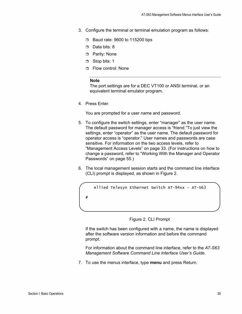
AT-S63 Management Software Menus Interface User’s Guide
3. Configure the terminal or terminal emulation program as follows:
Baud rate: 9600 to 115200 bps Data bits: 8Parity: NoneStop bits: 1Flow control: None
NoteThe port settings are for a DEC VT100 or ANSI terminal, or an equivalent terminal emulator program.
4. Press Enter.
You are prompted for a user name and password.
5. To configure the switch settings, enter “manager” as the user name. The default password for manager access is “friend.“To just view the settings, enter “operator” as the user name. The default password for operator access is “operator.” User names and passwords are case sensitive. For information on the two access levels, refer to “Management Access Levels” on page 33. (For instructions on how to change a password, refer to “Working With the Manager and Operator Passwords” on page 55.)
6. The local management session starts and the command line interface (CLI) prompt is displayed, as shown in Figure 2.
Figure 2. CLI Prompt
If the switch has been configured with a name, the name is displayed after the software version information and before the command prompt.
For information about the command line interface, refer to the AT-S63 Management Software Command Line Interface User’s Guide.
7. To use the menus interface, type menu and press Return.
Allied Telesyn Ethernet Switch AT-94xx - AT-S63
#
Section I: Basic Operations 39
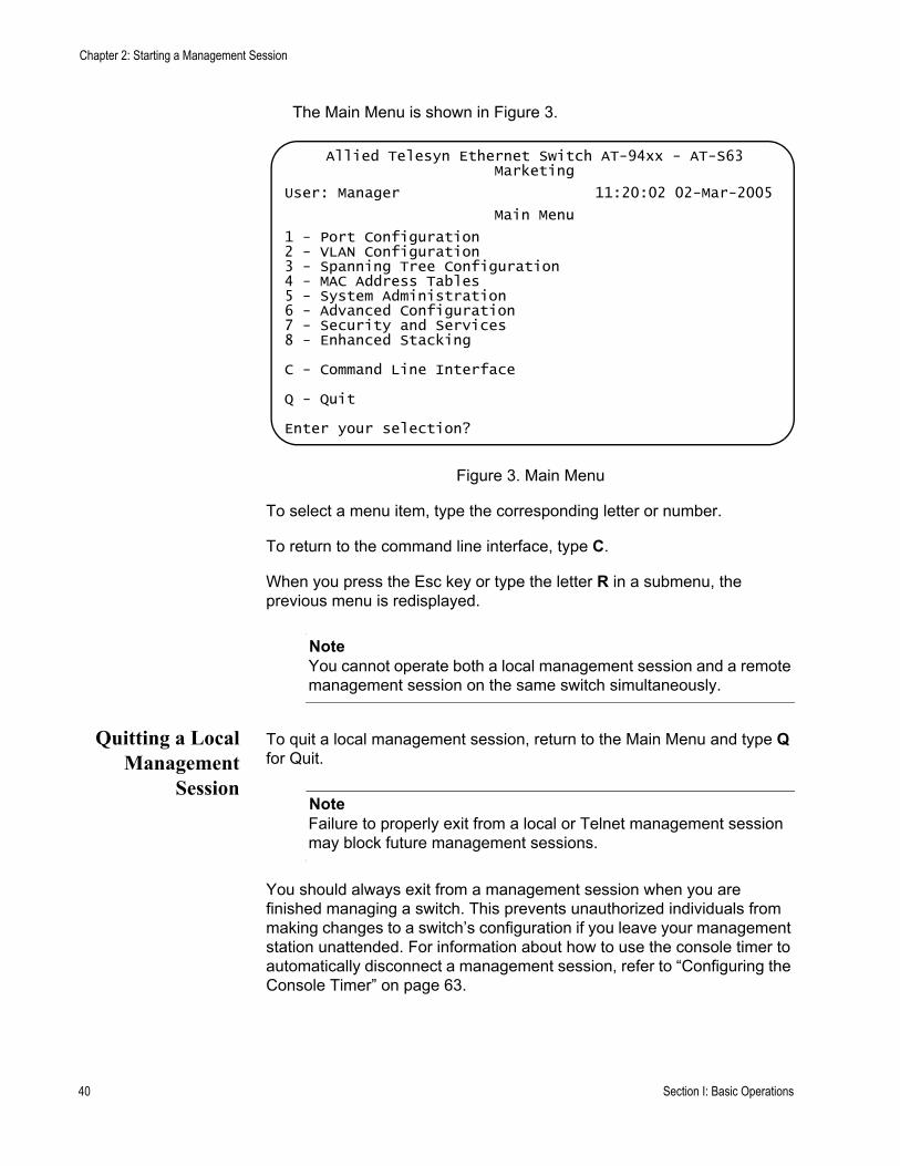
Chapter 2: Starting a Management Session
The Main Menu is shown in Figure 3.
Figure 3. Main Menu
To select a menu item, type the corresponding letter or number.
To return to the command line interface, type C.
When you press the Esc key or type the letter R in a submenu, the previous menu is redisplayed.
NoteYou cannot operate both a local management session and a remote management session on the same switch simultaneously.
Quitting a LocalManagement
Session
To quit a local management session, return to the Main Menu and type Q for Quit.
NoteFailure to properly exit from a local or Telnet management session may block future management sessions.
You should always exit from a management session when you are finished managing a switch. This prevents unauthorized individuals from making changes to a switch’s configuration if you leave your management station unattended. For information about how to use the console timer to automatically disconnect a management session, refer to “Configuring the Console Timer” on page 63.
Allied Telesyn Ethernet Switch AT-94xx - AT-S63Marketing
User: Manager 11:20:02 02-Mar-2005
Main Menu
1 - Port Configuration2 - VLAN Configuration3 - Spanning Tree Configuration4 - MAC Address Tables5 - System Administration6 - Advanced Configuration7 - Security and Services8 - Enhanced Stacking
C - Command Line Interface
Q - Quit
Enter your selection?
40 Section I: Basic Operations
AT-S63 Management Software Menus Interface User’s Guide
Starting a Remote Management Session
You can use the Telnet application from any workstation on your network to connect to an AT-9400 Series switch, as described in “Remote Connection” on page 31. When you make the connection and start the AT-S63 menus interface, you start a remote management session.
To manage a switch using remote connection, it must have an IP address or be part of an enhanced stack. To assign an IP address to a remote switch, refer to “Configuring the IP Address, Switch Name, and Other Basic Parameters” on page 46.
When you make a remote connection to a switch that has been configured as a master switch of an enhanced stack, you can manage all the switches that support enhanced stacking in the subnet from the same local management session. Therefore, you do not need to start a separate remote management session for each switch.
When you start a remote management session on a switch that is not part of an enhanced stack or that is a slave switch, you can only manage that switch.
NoteFor information on enhanced stacking, refer to “Enhanced Stacking Overview” on page 90.
Starting aRemote
ManagementSession
To make a remote connection, perform the following procedure:
1. In the Telnet application, specify the IP address of the master switch of the enhanced stack.
You are prompted for a user name and password.
2. To configure the switch settings, enter “manager” as the user name. The default password for manager access is “friend. “To just view the settings, enter “operator” as the user name. The default password for operator access is “operator.” User names and passwords are case sensitive. For information on the two access levels, refer to “Management Access Levels” on page 33. (For instructions on how to change a password, refer to “Working With the Manager and Operator Passwords” on page 55.)
3. The local management session starts and the command line interface (CLI) prompt is displayed, as shown in Figure 2 on page 39.
If the switch has been configured with a name, the name is displayed after the software version information and before the command prompt.
Section I: Basic Operations 41
Chapter 2: Starting a Management Session
For information about the command line interface, refer to the AT-S63 Management Software Command Line Interface User’s Guide.
4. To use the menus interface, type menu and press Return.
The Main Menu is shown in Figure 3 on page 40.
To select a menu item, type the corresponding letter or number.
To return to the command line interface, type C.
When you press the Esc key or type the letter R in a submenu, the previous menu is redisplayed.
NoteYou cannot operate both a local management session and a remote management session on the same switch simultaneously.
Quitting aRemote
ManagementSession
To end a remote management session, return to the Main Menu and type Q for Quit.
NoteFailure to properly exit from a local or Telnet management session may block future management sessions until the console timer times out.
You should always exit from a management session when you are finished managing a switch. This prevents unauthorized individuals from making changes to a switch’s configuration if you leave your management station unattended. For information about how to use the console timer to automatically disconnect a management session, refer to “Configuring the Console Timer” on page 63.
42 Section I: Basic Operations
Chapter 3
Basic Switch Parameters
This chapter contains a variety of information and procedures for basic switch setup. Sections in the chapter include:
“When Does a Switch Need an IP Address?” on page 44“Configuring the IP Address, Switch Name, and Other Basic Parameters” on page 46“Activating the BOOTP or DHCP Client Software” on page 49“Displaying the AT-9400 Series Switch Hardware and Software Information” on page 51“Rebooting a Switch” on page 53“Working With the Manager and Operator Passwords” on page 55“Setting the System Time” on page 58“Configuring the Console Startup Mode” on page 62“Configuring the Console Timer” on page 63“Enabling or Disabling the Telnet Server” on page 64“Setting the Baud Rate of the Serial Terminal Port” on page 65“Pinging a Remote System” on page 66“Returning the AT-S63 Management Software to the Factory Default Values” on page 67“Displaying System Hardware Information” on page 69“Displaying Uplink Port Information” on page 71
Section I: Basic Operations 43
Chapter 3: Basic Switch Parameters
When Does a Switch Need an IP Address?
One of the tasks of building or expanding a network is deciding which managed switches need to be assigned a unique IP address. The rule was that a managed switch needed an IP address if you wanted to manage it remotely, such as with the Telnet application. However, if a network contained many managed switches, assigning each one an IP address was often cumbersome and time consuming. It was also often difficult to keep track of all the IP addresses.
The enhanced stacking feature of the AT-8400 and AT-9400 series switches simplifies all this. With enhanced stacking, you need to assign an IP address to only one switch in each subnet in your network. The switch with the IP address is referred to as the master switch of the subnetwork. All switches in the same subnet share the IP address.
When you start a local or remote management session on the master switch, you have complete management access to all the other switches in the same subnet.
This feature has two primary benefits. First, it helps reduce the number of IP addresses you must assign to your network devices. Second, it allows you to configure multiple switches through the same local or remote management session.
If your network consists of multiple subnets, you must assign a unique IP address to at least one switch in each subnet. The switch with the IP address is the master switch of that subnet.
When you assign a switch an IP address, you must also assign it a subnet mask. The switch uses the subnet mask to determine which portion of an IP address represents the network address and which the node address.
You must also assign the switch a gateway address if there is a router between the switch and the remote management station. This gateway address is the IP address of the router through which the switch and management station communicates.
NoteFor further information on enhanced stacking, refer to “Enhanced Stacking Overview” on page 90.
If you do not plan to remotely manage the AT-94xx switches in your network, then you do not need to assign an IP address to any of them. The switches operate without an IP address and you can completely manage them from a local management session, if needed.
44 Section I: Basic Operations
AT-S63 Management Software Menus Interface User’s Guide
How Do YouAssign an IP
Address?
There are two ways that a switch can obtain an IP address.
The first way is for you to assign the IP configuration information manually. The procedure for this is explained in “Configuring the IP Address, Switch Name, and Other Basic Parameters” on page 46. You can initially assign an IP address to a switch only through a local management session.
The second method is for you to activate the BOOTP and DHCP client software on the switch and have the switch automatically download its IP configuration information from a BOOTP or DHCP server on your network. This procedure is explained in “Activating the BOOTP or DHCP Client Software” on page 49.
Section I: Basic Operations 45
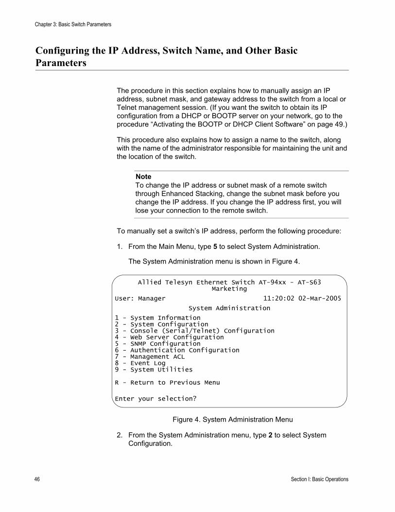
Chapter 3: Basic Switch Parameters
Configuring the IP Address, Switch Name, and Other Basic Parameters
The procedure in this section explains how to manually assign an IP address, subnet mask, and gateway address to the switch from a local or Telnet management session. (If you want the switch to obtain its IP configuration from a DHCP or BOOTP server on your network, go to the procedure “Activating the BOOTP or DHCP Client Software” on page 49.)
This procedure also explains how to assign a name to the switch, along with the name of the administrator responsible for maintaining the unit and the location of the switch.
NoteTo change the IP address or subnet mask of a remote switch through Enhanced Stacking, change the subnet mask before you change the IP address. If you change the IP address first, you will lose your connection to the remote switch.
To manually set a switch’s IP address, perform the following procedure:
1. From the Main Menu, type 5 to select System Administration.
The System Administration menu is shown in Figure 4.
Figure 4. System Administration Menu
2. From the System Administration menu, type 2 to select System Configuration.
Allied Telesyn Ethernet Switch AT-94xx - AT-S63Marketing
User: Manager 11:20:02 02-Mar-2005
System Administration
1 - System Information2 - System Configuration3 - Console (Serial/Telnet) Configuration4 - Web Server Configuration5 - SNMP Configuration6 - Authentication Configuration7 - Management ACL8 - Event Log9 - System Utilities
R - Return to Previous Menu
Enter your selection?
46 Section I: Basic Operations
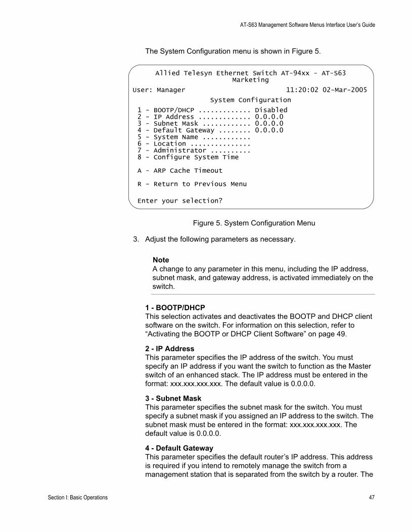
AT-S63 Management Software Menus Interface User’s Guide
The System Configuration menu is shown in Figure 5.
Figure 5. System Configuration Menu
3. Adjust the following parameters as necessary.
NoteA change to any parameter in this menu, including the IP address, subnet mask, and gateway address, is activated immediately on the switch.
1 - BOOTP/DHCPThis selection activates and deactivates the BOOTP and DHCP client software on the switch. For information on this selection, refer to “Activating the BOOTP or DHCP Client Software” on page 49.
2 - IP AddressThis parameter specifies the IP address of the switch. You must specify an IP address if you want the switch to function as the Master switch of an enhanced stack. The IP address must be entered in the format: xxx.xxx.xxx.xxx. The default value is 0.0.0.0.
3 - Subnet MaskThis parameter specifies the subnet mask for the switch. You must specify a subnet mask if you assigned an IP address to the switch. The subnet mask must be entered in the format: xxx.xxx.xxx.xxx. The default value is 0.0.0.0.
4 - Default GatewayThis parameter specifies the default router’s IP address. This address is required if you intend to remotely manage the switch from a management station that is separated from the switch by a router. The
Allied Telesyn Ethernet Switch AT-94xx - AT-S63Marketing
User: Manager 11:20:02 02-Mar-2005
System Configuration
1 - BOOTP/DHCP ............. Disabled2 - IP Address ............. 0.0.0.03 - Subnet Mask ............ 0.0.0.04 - Default Gateway ........ 0.0.0.05 - System Name ............6 - Location ...............7 - Administrator ..........8 - Configure System Time
A - ARP Cache Timeout
R - Return to Previous Menu
Enter your selection?
Section I: Basic Operations 47

Chapter 3: Basic Switch Parameters
address must be entered in the format: xxx.xxx.xxx.xxx. The default value is 0.0.0.0.
5 - System NameThis parameter specifies a name for the switch (for example, Sales Ethernet switch). The name is displayed at the top of the AT-S63 management menus and pages. The name can be from 1 to 39 characters. The name can include spaces and special characters, such as exclamation points and asterisks. The default is no name. This parameter is optional.
NoteAllied Telesyn recommends that you assign each switch a name. Names can help you identify the various switches in your network and help you avoid performing a configuration procedure on the wrong switch.
6 - LocationThis parameter specifies the location of the switch, (for example, 4th Floor - rm 402B). The location can be from 1 to 20 characters. The location can include spaces and special characters, such as dashes and asterisks. The default is no location. This parameter is optional.
7 - AdministratorThis parameter specifies the name of the network administrator responsible for managing the switch. The name can be from 1 to 20 characters. It can include spaces and special characters, such as dashes and asterisks. The default is no name. This parameter is optional.
NoteItem 8, Configure System Time, is described in “Setting the System Time” on page 58. Item A, ARP Cache Timeout, is described in “Setting the ARP Cache Timeout” on page 168.
4. After making changes, type R until you return to the Main Menu. Then type S to select Save Configuration Changes.
48 Section I: Basic Operations
AT-S63 Management Software Menus Interface User’s Guide
Activating the BOOTP or DHCP Client Software
The BOOTP and DHCP protocols were developed to simplify network management. They are used to automatically assign IP configuration information to the devices on your network, such as an IP address, subnet mask, and a default gateway address.
The AT-9400 Series switch contains the client software for these protocols and can obtain its IP configuration information from a BOOTP or DHCP server on your network. If you activate this feature, the switch seeks its IP address and other IP configuration information from a BOOTP or DHCP server on your network whenever you reset or power ON the device.
In order for this strategy to work, there must be a BOOTP or DHCP server that resides on your network and you must configure the service by entering the switch’s MAC address.
BOOTP and DHCP services typically allow you to specify how the IP address is to be assigned to the switch. The choices are static and dynamic. If you choose static, the server always assigns the same IP address to the switch when the switch is reset or powered ON. This is the preferred configuration. Because the BOOTP and DHCP services always assigns the same IP address to a switch, you always know which IP address to use when you need to remotely manage a particular switch.
If you choose dynamic, the server assigns any unused IP address that it has not already assigned to another device. This means that a switch might have a different IP address each time you reset or power cycle the device, which makes it difficult for you to remotely manage the unit.
NoteThe BOOTP and DHCP client software is disabled by default on the switch.
To activate or deactivate the BOOTP or DHCP client software, perform the following procedure:
1. From the Main Menu, type 5 to select System Administration.
The System Administration menu is shown in Figure 4 on page 46.
2. From the System Administration menu, type 2 to select System Configuration.
The System Configuration menu is shown in Figure 5 on page 47.
3. From the System Configuration menu, type 1 to select BOOTP/DHCP.
Section I: Basic Operations 49
Chapter 3: Basic Switch Parameters
The following prompt is displayed:
DHCP/BOOTP/DISABLE: (1-DHCP, 2-BOOTP, 3-DISABLE):
4. Type 1 to enable DHCP, 2 to enable BOOTP, or 3 to disable the services and press Return. The default is disabled.
NoteIf you activated BOOTP or DHCP, the switch immediately begins to query the network for a BOOTP or DHCP server. The switch continues to query the network for its IP configuration until it receives a response.
Any static IP address, subnet mask, or gateway address assigned to the switch is deleted from the System Configuration menu and replaced with the value the switch receives from the BOOTP or DHCP server. If you later disable BOOTP and DHCP, these values are returned to their default settings.
5. After making changes, type R until you return to the Main Menu. Then type S to select Save Configuration Changes.
50 Section I: Basic Operations
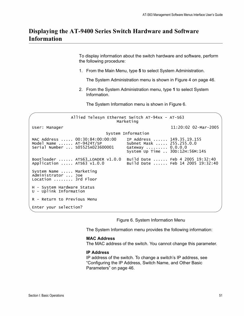
AT-S63 Management Software Menus Interface User’s Guide
Displaying the AT-9400 Series Switch Hardware and Software Information
To display information about the switch hardware and software, perform the following procedure:
1. From the Main Menu, type 5 to select System Administration.
The System Administration menu is shown in Figure 4 on page 46.
2. From the System Administration menu, type 1 to select System Information.
The System Information menu is shown in Figure 6.
Figure 6. System Information Menu
The System Information menu provides the following information:
MAC AddressThe MAC address of the switch. You cannot change this parameter.
IP AddressIP address of the switch. To change a switch’s IP address, see “Configuring the IP Address, Switch Name, and Other Basic Parameters” on page 46.
Allied Telesyn Ethernet Switch AT-94xx - AT-S63Marketing
User: Manager 11:20:02 02-Mar-2005
System Information
MAC Address ..... 00:30:84:00:00:00 IP Address ...... 149.35.19.155Model Name ...... AT-9424T/SP Subnet Mask ..... 255.255.0.0Serial Number ... S05525A023600001 Gateway ......... 0.0.0.0
System Up Time .. 30D:12H:56M:14S
Bootloader ...... ATS63_LOADER v1.0.0 Build Date ...... Feb 4 2005 19:32:40Application ..... ATS63 v1.0.0 Build Date ...... Feb 14 2005 19:32:40
System Name ..... MarketingAdministrator ... Joe Location ........ 3rd Floor
H - System Hardware StatusU - Uplink Information
R - Return to Previous Menu
Enter your selection?
Section I: Basic Operations 51

Chapter 3: Basic Switch Parameters
Model NameModel name of the AT-9400 Series switch. You cannot change this setting.
Subnet MaskSubnet mask assigned to the switch. To change the subnet mask, see “Configuring the IP Address, Switch Name, and Other Basic Parameters” on page 46.
Serial NumberSerial number of the switch. You cannot change this setting.
GatewayGateway assigned to the switch. To change the gateway, see “Configuring the IP Address, Switch Name, and Other Basic Parameters” on page 46.
System Up TimeThe number of days, hours, minutes, and seconds the switch has been operational. You cannot change this setting.
Bootloader and Build DateThe version of the bootloader software and the date it was built.
Application and Build DateThe version of the AT-S63 management software that the switch is currently running and the date it was built.
System NameThe name assigned to the switch. To change the name, see “Configuring the IP Address, Switch Name, and Other Basic Parameters” on page 46.
AdministratorThe administrator of the switch. To change the administrator’s name, see “Configuring the IP Address, Switch Name, and Other Basic Parameters” on page 46.
LocationThe location of the switch. To change the location information, see “Configuring the IP Address, Switch Name, and Other Basic Parameters” on page 46.
For information about selection H, System Hardware Status, refer to “Displaying System Hardware Information” on page 69. For information about selection U, Uplink Information, refer to “Displaying Uplink Port Information” on page 71.
52 Section I: Basic Operations
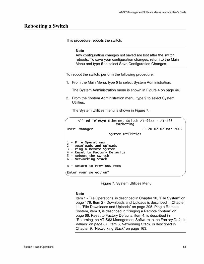
AT-S63 Management Software Menus Interface User’s Guide
Rebooting a Switch
This procedure reboots the switch.
NoteAny configuration changes not saved are lost after the switch reboots. To save your configuration changes, return to the Main Menu and type S to select Save Configuration Changes.
To reboot the switch, perform the following procedure:
1. From the Main Menu, type 5 to select System Administration.
The System Administration menu is shown in Figure 4 on page 46.
2. From the System Administration menu, type 9 to select System Utilities.
The System Utilities menu is shown in Figure 7.
Figure 7. System Utilities Menu
NoteItem 1 - File Operations, is described in Chapter 10, ”File System” on page 179. Item 2 - Downloads and Uploads is described in Chapter 11, ”File Downloads and Uploads” on page 205. Ping a Remote System, item 3, is described in “Pinging a Remote System” on page 66. Reset to Factory Defaults, item 4, is described in “Returning the AT-S63 Management Software to the Factory Default Values” on page 67. Item 6, Networking Stack, is described in Chapter 9, ”Networking Stack” on page 163.
Allied Telesyn Ethernet Switch AT-94xx - AT-S63Marketing
User: Manager 11:20:02 02-Mar-2005
System Utilities
1 - File Operations2 - Downloads and Uploads3 - Ping a Remote System4 - Reset to Factory Defaults5 - Reboot the Switch6 - Networking Stack
R - Return to Previous Menu
Enter your selection?
Section I: Basic Operations 53
Chapter 3: Basic Switch Parameters
3. From the System Utilities menu, type 5 to select Reboot the switch.
The following prompt is displayed:
The switch is about to reboot. Do you want to proceed? [Yes/No] ->
4. Type Y to reboot the switch or N to cancel the procedure.
CautionThe switch does not forward traffic while it reloads its operating software, a process that takes approximately 20 seconds to complete. Some packet traffic may be lost. After the switch finishes rebooting, you must reestablish your management session if you want to continue managing the unit.
54 Section I: Basic Operations

AT-S63 Management Software Menus Interface User’s Guide
Working With the Manager and Operator Passwords
There are two levels of management access on an AT-94xx switch: manager and operator. When you log in as manager, you can view and configure all of a switch’s operating parameters. When you log in as an operator, you can only view the operating parameters; you cannot change any values.
You log in as a manager or an operator when you enter the appropriate username and password when you start an AT-S63 management session. The default password for manager access is “friend.” The default password for operator access is “operator.” Passwords are case sensitive.
Changing theManager or
OperatorPassword
To change the manager or operator password, perform the following procedure:
1. From the Main Menu, type 5 to select System Administration.
The System Administration menu is shown in Figure 4 on page 46.
2. From the System Administration menu, type 6 to select Authentication Configuration.
The Authentication Configuration menu is shown in Figure 8.
Figure 8. Authentication Configuration Menu
3. From the Authentication Configuration menu, type 5 to select Passwords Configuration.
Allied Telesyn Ethernet Switch AT-94xx - AT-S63Marketing
User: Manager 11:20:02 02-Mar-2005
Authentication Configuration
1 - Server-based Authentication ..... Disabled2 - Authentication Method ........... TACACS+3 - TACACS+ Configuration4 - RADIUS Configuration5 - Passwords Configuration
R - Return to Previous Menu
Enter your selection?
Section I: Basic Operations 55
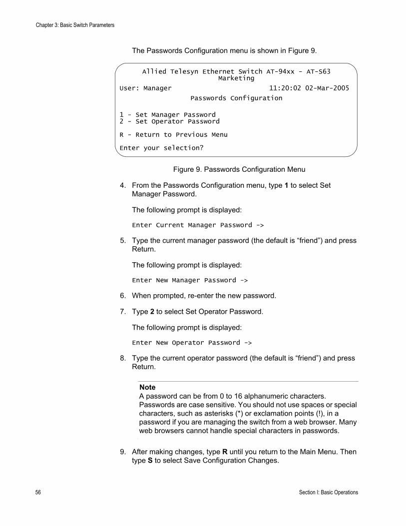
Chapter 3: Basic Switch Parameters
The Passwords Configuration menu is shown in Figure 9.
Figure 9. Passwords Configuration Menu
4. From the Passwords Configuration menu, type 1 to select Set Manager Password.
The following prompt is displayed:
Enter Current Manager Password ->
5. Type the current manager password (the default is “friend”) and press Return.
The following prompt is displayed:
Enter New Manager Password ->
6. When prompted, re-enter the new password.
7. Type 2 to select Set Operator Password.
The following prompt is displayed:
Enter New Operator Password ->
8. Type the current operator password (the default is “friend”) and press Return.
NoteA password can be from 0 to 16 alphanumeric characters. Passwords are case sensitive. You should not use spaces or special characters, such as asterisks (*) or exclamation points (!), in a password if you are managing the switch from a web browser. Many web browsers cannot handle special characters in passwords.
9. After making changes, type R until you return to the Main Menu. Then type S to select Save Configuration Changes.
Allied Telesyn Ethernet Switch AT-94xx - AT-S63Marketing
User: Manager 11:20:02 02-Mar-2005
Passwords Configuration
1 - Set Manager Password2 - Set Operator Password
R - Return to Previous Menu
Enter your selection?
56 Section I: Basic Operations

AT-S63 Management Software Menus Interface User’s Guide
Resetting theManagerPassword
If you change the manager password from the default and lose or forget it, you can reset the password. Note the following about this feature:
This procedure is only available through a local management session.A remote management session always requires a login and password.This procedure assumes that the switch is in a secure location accessible only to authorized personnel to ensure that only those authorized persons can make a local connection.When the local management session ends, such as the management session timing out, a login and password are required to log in again unless you perform this procedure again.If the AT-S63 management software detects another active management session when you perform this procedure, a message is displayed for the other user stating that the user will be logged off. Thus, this type of session takes precedence over any other user’s management session.After you reset the password, you do not need to reboot the switch.
To reset the manager password, perform the following procedure:
1. Reboot the switch.
2. When the switch displays “Press <Ctrl> B to go to Boot prompt,” type S or s instead.
You are not prompted for a login or password but you are logged in with manager privileges and the Main Menu is displayed, as shown in Figure 3 on page 40.
3. Follow the procedure in “Changing the Manager or Operator Password” on page 55 to reset the passwords.
Section I: Basic Operations 57
Chapter 3: Basic Switch Parameters
Setting the System Time
This procedure explains how to set the switch’s date and time. Setting the system time is important if you configured the switch to send traps to your management stations. Traps from a switch where the time has not been set do not contain the correct date and time. Therefore, it becomes difficult for you to determine when the events represented by the traps occurred.
It is also important to set the system time if you intend to use the Secure Sockets Layer (SSL) certificate feature described in, Chapter 32, ”PKI Certificates and SSL” on page 719. Certificates must contain the date and time when they are created.
There are two ways to set the switch’s time. One method is to set it manually. There is, however, a drawback to this method. The switch loses the values when reset or power cycled. When you use this method you must reset the values whenever you reset the device.
The second method uses the Simple Network Time Protocol (SNTP). The AT-S63 management software is shipped with the client version of this protocol. You can configure the AT-S63 management software to obtain the current date and time from an SNTP or Network Time Protocol (NTP) server located on your network or the Internet.
SNTP is a reduced version of the NTP. However, the SNTP client software in the AT-S63 management software is interoperable with NTP servers.
NoteThe default system time on the switch is midnight, January 1, 1970.
Setting theSystem Time
Manually
To set the system time manually, perform the following procedure:
1. From the Main Menu, type 5 to select System Administration.
The System Administration menu is shown in Figure 4 on page 46.
2. From the System Administration menu, type 2 to select System Configuration.
The System Configuration menu is shown in Figure 5 on page 47.
3. From the System Configuration menu, type 8 to select Configure System Time.
58 Section I: Basic Operations

AT-S63 Management Software Menus Interface User’s Guide
The Configure System Time menu is shown in Figure 10.
Figure 10. Configure System Time Menu
4. From the Configure System Time menu, type 1 to select System Time.
The following prompt is displayed:
Enter new system time [hh:mm:ss] ->
5. Enter a new time for the system in the following format: hours, minutes, and seconds all separated by colons.
The following prompt is displayed:
Enter new system date [dd-mm-yyyy] ->
6. Enter a new date for the system. Use two numbers to specify the day and month. Use four numbers to specify the year. Separate the values with hyphens. For example, December 5, 2004 is specified 05-12-2004.
The new time and date are immediately activated on the switch.
Setting theSystem Time
from an SNTP orNTP Server
To configure the switch to obtain its date and time from an SNTP or NTP server on your network or the Internet, perform the following procedure:
1. From the Main Menu, type 5 to select System Administration.
The System Administration menu is shown in Figure 4 on page 46.
2. From the System Administration menu, type 2 to select System Configuration.
The System Configuration menu is shown in Figure 5 on page 47.
Allied Telesyn Ethernet Switch AT-94xx - AT-S63Marketing
User: Manager 11:20:02 02-Mar-2005
Configure System Time
1 - System Time ................... 00:00:00 on 01-Jan-19702 - SNTP Status ................... Disabled3 - SNTP Server ................... 0.0.0.04 - UTC Offset .................... +05 - Daylight Savings Time (DST) ... Enabled6 - Poll Interval ................. 600 seconds7 - Last Delta .................... +0 seconds
U - Update System TimeR - Return to Previous Menu
Enter your selection?
Section I: Basic Operations 59
Chapter 3: Basic Switch Parameters
3. From the System Configuration menu, type 8 to select Configure System Time.
The Configure System Time menu is shown in Figure 10 on page 59.
4. Type 3 to select SNTP Server to enter the IP address of an SNTP server.
NoteIf the switch is obtaining its IP address and subnet mask from a DHCP server, you can configure the DHCP server to provide the switch with an IP address of an NTP or SNTP server. If you configured the DHCP server to provide this address, then you do not need to enter it here, and you can skip ahead to step 5.
The following prompt is displayed:
Enter SNTP server IP address ->
5. Enter an IP address of an SNTP or NTP server.
6. Type 4 to select UTC Offset to specify the difference between the UTC and local time.
NoteIf the switch is using DHCP, it automatically attempts to determine this value. In this case, you do not need to configure a value for the UTC Offset parameter.
The following prompt is displayed:
Enter UTC Offset [-12 to 12] -> 0
7. Enter a UTC Offset time.
The default is 0 hours. The range is -12 to +12 hours.
8. Type 5 to select Daylight Savings Time (DST) to enable or disable the switch’s ability to adjust its system time to daylight savings time. The following prompt is displayed:
Adjust for Daylight Savings Time (E - Enabled, D - Disabled) ->
9. Type E to enable daylight savings time and allow the switch to adjust system time to daylight savings time. This is the default value. Type D to disable daylight savings time and not allow the switch to adjust system time to daylight savings time.
60 Section I: Basic Operations
AT-S63 Management Software Menus Interface User’s Guide
NoteThe switch does not set DST automatically. If the switch is in a locale that uses DST, you must remember to enable this in April when DST begins and disable it in October when DST ends. If the switch is in a locale that does not use DST, this option should be set to disabled all the time.
10. Type 6 to select Poll Interval to specify the time interval between queries to the SNTP server.
The following prompt is displayed:
Enter interval to poll SNTP server [60 to 1200] -> 600
NoteSelection 7, Last Delta, reports the last adjustment that had to be applied to the system time; the drift in the system clock between two successive queries to the SNTP server. You cannot change this value.
11. Enter the number of seconds the switch waits between polling the SNTP or NTP server. The default is 600 seconds. The range is from 60 to 1200 seconds.
12. Type 2 to select SNTP Status to enable or disable the SNTP client.
The following prompt is displayed:
SNTP Status (E-Enabled, D-Disabled) ->
13. Type E to enable SNTP client software on the switch or D to disable the NTP client software and press Return. The default is disabled.
After SNTP is enabled, the switch immediately polls the SNTP or NTP server for the current date and time. (The switch also automatically polls the server whenever a change is made to any of the parameters in this menu, so long as SNTP is enabled.)
The Last Delta option in the menu displays the last adjustment that was applied to system time due to a drift in the system clock between two successive queries to the SNTP server. This is a read only field.
Option U, Update System Time, allows you to prompt the switch to poll the SNTP or NTP server for the current time and date. You can use this selection to update the time and date immediately rather than wait for the switch’s next polling period. This selection has no effect if you set the date and time manually.
14. After making changes, type R until you return to the Main Menu. Then type S to select Save Configuration Changes.
Section I: Basic Operations 61

Chapter 3: Basic Switch Parameters
Configuring the Console Startup Mode
You can configure the AT-S63 management software to display either the Main Menu or the command line interface prompt whenever you start a local or Telnet management session. The default is the command line interface.
To change the console startup mode, perform the following procedure:
1. From the Main Menu, type 5 to select System Administration.
The System Administration menu is shown in Figure 4 on page 46.
2. From the System Administration menu, type 3 to select Console (Serial/Telnet) Configuration.
The Console (Serial/Telnet) Configuration menu is shown in Figure 11.
Figure 11. Console (Serial/Telnet) Configuration Menu
3. Type 1 to toggle Console Startup Mode between Menu and CLI. When the mode is set to Menu, a management session starts by displaying the Main Menu. When the mode is set to CLI, a management session starts with the command line interface prompt. The system default is CLI.
4. After making changes, type R until you return to the Main Menu. Then type S to select Save Configuration Changes.
A change to the console startup mode takes effect the next time you start a local management session.
Allied Telesyn Ethernet Switch AT-94xx - AT-S63Marketing
User: Manager 11:20:02 02-Mar-2005
Console (Serial/Telnet) Configuration
1 - Console Startup Mode ............ CLI2 - Console Disconnect Interval ..... 10 minute(s)3 - Console Baud Rate ............... 96004 - Telnet Server ................... Enabled
R - Return to Previous Menu
Enter your selection?
62 Section I: Basic Operations

AT-S63 Management Software Menus Interface User’s Guide
Configuring the Console Timer
The AT-S63 management software uses the console timer, also referred to as the console disconnect interval, to automatically end inactive local and remote management sessions. A management session is automatically ended if the management software does not detect any activity from a local or remote management station after the console timer has expired. For example, if you specify two minutes as the console timer, the AT-S63 management software automatically ends a management session if it does not detect any activity from the local or remote management station after two minutes.
This security feature prevents unauthorized individuals from using your management station when you step away from your system while you are configuring a switch. The default for the console timeout value is 10 minutes.
To adjust the console timer, perform the following procedure:
1. From the Main Menu, type 5 to select System Administration.
The System Administration menu is shown in Figure 4 on page 46.
2. From the System Administration menu, type 3 to select Console (Serial/Telnet) Configuration.
The Console (Serial/Telnet) Configuration menu is shown in Figure 11 on page 62.
3. From the Console (Serial/Telnet) Configuration menu, type 2 to select Console Disconnect Interval
The following prompt is displayed:
Enter your new value -> [1 to 60]->
4. Enter a new console timer value. The range is 1 to 60 minutes. The default is 10 minutes.
A change to the console timer is immediately activated on the switch.
5. After making changes, type R until you return to the Main Menu. Then type S to select Save Configuration Changes.
Section I: Basic Operations 63

Chapter 3: Basic Switch Parameters
Enabling or Disabling the Telnet Server
This procedure describes how to enable or disable the Telnet server on the switch. You might disable the server to prevent individuals from managing the switch with the Telnet application if you intend to use the Secure Shell (SSH) protocol.
To enable or disable the Telnet server, perform the following procedure:
1. From the Main Menu, type 5 to select System Administration.
The System Administration menu is shown in Figure 4 on page 46.
2. From the System Administration menu, type 3 to select Console (Serial/Telnet) Configuration.
The Console (Serial/Telnet) Configuration menu is shown in Figure 11 on page 62.
3. From the Console (Serial/Telnet) Configuration menu, type 4 to toggle Telnet Server between Enabled and Disabled.
NoteDisable Telnet access if you are using the SSH (Secure Shell) feature. (The SSH feature is not available in all versions of the AT-S63 management software.)
4. After making changes, type R until you return to the Main Menu. Then type S to select Save Configuration Changes.
64 Section I: Basic Operations
AT-S63 Management Software Menus Interface User’s Guide
Setting the Baud Rate of the Serial Terminal Port
The default baud rate of the RJ-45 type serial terminal port on the switch is 9600 bps.
To change the baud rate, perform the following procedure:
1. From the Main Menu, type 5 to select System Administration.
The System Administration menu is shown in Figure 4 on page 46.
2. From the System Administration menu, type 3 to select Console (Serial/Telnet) Configuration.
The Console (Serial/Telnet) Configuration menu is shown in Figure 11 on page 62.
3. From the Console (Serial/Telnet) Configuration menu, type 3 to select Console Baud Rate.
The following prompt is displayed:
Supported baud rates are:1200, 2400, 4800, 9600, 19200, 38400, 57600, or 115200Enter new baud rate value --> [1200 to 115200]
4. Type the desired baud rate value and press Return.
The following message is displayed:
Baud rate changed to [baud rate you typed] bps.Please change your terminal baud rate correspondingly.Press <Enter> to continue.
NoteIf you are running a local management session, be sure to change your terminal’s baud rate.
5. Press Return.
Section I: Basic Operations 65
Chapter 3: Basic Switch Parameters
Pinging a Remote System
You can instruct the switch to ping a remote device on your network. This procedure is useful in determining whether a valid link exists between the switch and another device.
NoteTo perform this procedure, the switch must have an IP address.
To instruct the switch to ping a network device, perform the following procedure:
1. From the Main Menu, type 5 to select System Administration.
The System Administration menu is shown in Figure 4 on page 46.
2. From the System Administration menu, type 9 to select System Utilities.
The System Utilities menu is shown in Figure 7 on page 53.
3. For the System Utilities menu, type 3 to select Ping a Remote System.
The following prompt is displayed:
Please enter an IP address ->
4. Enter the IP address of the end node you want the switch to ping.
The results of the ping command are displayed on the screen.
5. To stop the ping, press any key.
66 Section I: Basic Operations

AT-S63 Management Software Menus Interface User’s Guide
Returning the AT-S63 Management Software to the Factory Default Values
The procedure in this section returns all AT-S63 management software parameters to the default values. Please note the following before you perform this procedure:
Returning all parameter settings to their default values also deletes any port-based or tagged VLANs you created on the switch.This procedure does not delete files from the AT-S63 file system. To delete files, refer to Chapter 10, ”File System” on page 179.This procedure does not delete any encryption keys stored in the key database. To delete encryption keys, refer to “Deleting an Encryption Key” on page 709.Returning a switch to its default values does not alter the contents of the active boot configuration file. To reset the file back to the default settings, you must reestablish your management session after the switch reboots and then select Save Configuration changes. Otherwise the switch reverts back to the previous configuration the next time you reset the switch.
NoteThe AT-S63 management software default values are listed in Appendix 1, ”AT-S63 Default Settings” on page 1.
To return the AT-S63 management software to the default settings, perform the following procedure:
1. From the Main Menu, type 5 to select System Administration.
The System Administration menu is shown in Figure 4 on page 46.
2. From the System Administration menu, type 9 to select System Utilities.
The System Utilities menu is shown in Figure 7 on page 53.
3. From the System Utilities menu, type 4 to select Reset to Factory Defaults.
The following prompt is displayed:
Do you want to reset to factory defaults? [Yes/No] ->
4. Type Y for yes or N to cancel the procedure.
If you respond with yes, the following prompt is displayed:
Section I: Basic Operations 67
Chapter 3: Basic Switch Parameters
Do you want to reset static IP, Subnet and Gateway? [Yes/No] ->
5. If you type Y for yes, all switch parameters including the IP address, subnet mask, and gateway address are changed to the default values. If you type N for no, all switch parameters excluding the IP address, subnet mask, and gateway address are changed to the default values.
The following prompt is displayed:
The Factory Defaults take effect only after the Switch reboots.Do you want to reboot the Switch now? [Yes/No] ->
6. Type Y to reset the switch.
CautionThe switch does not forward traffic while it reloads its operating software, a process that takes approximately 20 seconds to complete. Some packet traffic may be lost. You must reestablish your management session if you want to continue managing the switch.
7. Reestablish your management session.
8. From the Main Menu, type S to select Save Configuration Changes.
This step returns the active boot configuration file back to the default settings.
68 Section I: Basic Operations

AT-S63 Management Software Menus Interface User’s Guide
Displaying System Hardware Information
You can view information about the system hardware, including details about the fans and temperature settings.
To display the system hardware information, perform the following procedure:
1. From the Main Menu, type 5 to select System Administration.
The System Administration menu is shown in Figure 4 on page 46.
2. From the System Administration menu, type 1 to select System Information
The System Information menu is shown in Figure 6 on page 51.
3. From the System Information menu, type H to select System Hardware Status.
NoteMenu selection U, Uplink Information, is described in “Displaying Uplink Port Information” on page 71.
The System Hardware Status menu is shown in Figure 12.
Figure 12. System Hardware Information Menu
Allied Telesyn Ethernet Switch AT-94xx - AT-S63Marketing
User: Manager 11:20:02 02-Mar-2005
System Hardware Status
System 1.25 V Power ............. 1.28VSystem 1.8V Power ............... 1.76VSystem 2.5V Power ............... 2.48VSystem 3.3V Power ............... 3.2VSystem 5V Power ................. 5.0VSystem 12V Power ................ 11.68VSystem Temperature (Celsius) .... 36 CSystem Fan Speed ................ 3970 RPM
Main PSU ........................ OnRPS ............................. Not Connected
U - Update DisplayR - Return to Previous Menu
Enter your selection?
Section I: Basic Operations 69
Chapter 3: Basic Switch Parameters
The System Hardware Information menu provides the following information:
System 1.25 V PowerSystem 1.8V PowerSystem 2.5 V PowerSystem 3.3 V PowerSystem 5 V PowerSystem 12 V PowerThe current voltage of the six power supplies in the switch.
System Temperature (Celsius)The overall system temperature.
System Fan SpeedThe system fan speed.
Main PSURPSThe status of the main power supply unit (PSU) and the redundant power supply (RPS).
NoteThe information displayed in this menu varies, depending upon the switch model.
4. Return to the Main Menu.
70 Section I: Basic Operations
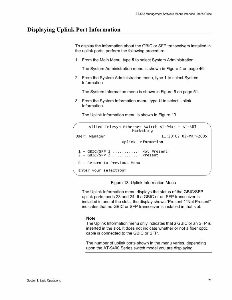
AT-S63 Management Software Menus Interface User’s Guide
Displaying Uplink Port Information
To display the information about the GBIC or SFP transceivers installed in the uplink ports, perform the following procedure:
1. From the Main Menu, type 5 to select System Administration.
The System Administration menu is shown in Figure 4 on page 46.
2. From the System Administration menu, type 1 to select System Information
The System Information menu is shown in Figure 6 on page 51.
3. From the System Information menu, type U to select Uplink Information.
The Uplink Information menu is shown in Figure 13.
Figure 13. Uplink Information Menu
The Uplink Information menu displays the status of the GBIC/SFP uplink ports, ports 23 and 24. If a GBIC or an SFP transceiver is installed in one of the slots, the display shows “Present.” “Not Present” indicates that no GBIC or SFP transceiver is installed in that slot.
NoteThe Uplink Information menu only indicates that a GBIC or an SFP is inserted in the slot. It does not indicate whether or not a fiber optic cable is connected to the GBIC or SFP.
The number of uplink ports shown in the menu varies, depending upon the AT-9400 Series switch model you are displaying.
Allied Telesyn Ethernet Switch AT-94xx - AT-S63Marketing
User: Manager 11:20:02 02-Mar-2005
Uplink Information
1 - GBIC/SFP 1 ............ Not Present2 - GBIC/SFP 2 ............ Present
R - Return to Previous Menu
Enter your selection?
Section I: Basic Operations 71

Chapter 3: Basic Switch Parameters
4. Type the number corresponding to the slot where the transceiver is identified as “Present” to view detailed information about that transceiver. The information displayed depends upon the transceiver vendor and whether the slot contains an SFP or a GBIC transceiver.
The GBIC/SFP Information menu (page 1) is displayed. Figure 14 shows some possible fields for an SFP.
Figure 14. GBIC/SFP Information Menu (Page 1)
5. Type N for Next Page to view more information.
Allied Telesyn Ethernet Switch AT-94xx - AT-S63Marketing
User: Manager 11:20:02 02-Mar-2005
GBIC/SFP 2 Information
Transceiver Identifier ..................... SFPExtended Transceiver Identifier ............ Function defined by serial IDConnector Type ............................. LCEncoding Algorithm ......................... 8B20BNominal Bit Rate ........................... 2100M Bits/secLink Length Supported for 9 um Fiber ....... 0mLink Length Supported for 50 um Fiber ...... 300mLink Length Supported for 62.5 um Fiber .... 150mLink Length Supported for Copper ........... 0m
N - Next PageU - Update DisplayR - Return to Previous Menu
Enter your selection?
72 Section I: Basic Operations
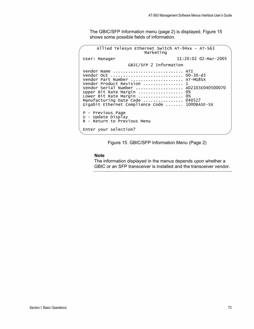
AT-S63 Management Software Menus Interface User’s Guide
The GBIC/SFP Information menu (page 2) is displayed. Figure 15 shows some possible fields of information.
Figure 15. GBIC/SFP Information Menu (Page 2)
NoteThe information displayed in the menus depends upon whether a GBIC or an SFP transceiver is installed and the transceiver vendor.
Allied Telesyn Ethernet Switch AT-94xx - AT-S63Marketing
User: Manager 11:20:02 02-Mar-2005
GBIC/SFP 2 Information
Vendor Name ............................ ATIVendor OUI ............................. 00-30-d3Vendor Part Number ..................... AT-MG8SXVendor Product Revision ................ 1Vendor Serial Number ................... A02103E040500070Upper Bit Rate Margin .................. 0%Lower Bit Rate Margin .................. 0%Manufacturing Date Code ................ 040527Gigabit Ethernet Compliance Code ....... 1000BASE-SX
P - Previous PageU - Update DisplayR - Return to Previous Menu
Enter your selection?
Section I: Basic Operations 73

Chapter 3: Basic Switch Parameters
74 Section I: Basic Operations
Chapter 4
SNMPv1 and SNMPv2c
This chapter explains how to activate SNMP management on the switch and how to create, modify, and delete SNMPv1 and SNMPv2c community strings. Sections in the chapter include:
“SNMPv1 and SNMPv2c Overview” on page 76“Enabling or Disabling SNMP Management” on page 79“Setting the Authentication Failure Trap” on page 80“Creating an SNMP Community String” on page 81“Modifying a Community String” on page 84“Displaying the SNMP Community Strings” on page 88
Section I: Basic Operations 75
Chapter 4: SNMPv1 and SNMPv2c
SNMPv1 and SNMPv2c Overview
The Simple Network Management Program (SNMP) is another way for you to manage the switch. This type of management involves viewing and changing the management information base (MIB) objects on the device using an SNMP application program.
The AT-S63 management software supports SNMPv1, SNMPv2c, and SNMPv3. This chapter explains how to configure the switch’s software for SNMPv1 and SNMPv2c. For instructions on how to configure the switch for SNMPv3, refer to Chapter 20, ”SNMPv3” on page 369.
The procedures in this chapter show you how to create and manage SNMPv1 and SNMPv2c community strings through which your SNMP application program at your management workstation can access the switch’s MIB objects.
You can also configure SNMPv1 and SNMPv2c with the SNMPv3 Table menus described in Chapter 20, ”SNMPv3” on page 369. However, because the SNMPv3 Table menus require a much more extensive configuration, Allied Telesyn recommends configuring SNMPv1 and SNMPv2c with the procedures in this chapter.
To manage a switch using an SNMP application program, you must do the following:
Activate SNMP management on the switch. The default setting for SNMP management is disabled. The procedure for this can be found in “Enabling or Disabling SNMP Management” on page 79.Load the Allied Telesyn MIBs for the switch onto your management workstation containing the SNMP application program. The MIBs are available from the Allied Telesyn web site at www.alliedtelesyn.com.
To manage a switch using SNMP, you need to know the IP address of the switch or of a master switch and at least one of the switch’s community strings. A community string is a string of alphanumeric characters that gives you access to the switch.
A community string has several attributes that you can use to control who can use the string and what the string will allow a network management to do on the switch. The community string attributes are defined below:
Community String NameYou must give the community string a name. The name can be from one to eight alphanumeric characters. Spaces are allowed.
Access ModeThis defines what the community string will allow a network manager to do. There are two access modes: Read and Read/Write. A community
76 Section I: Basic Operations

AT-S63 Management Software Menus Interface User’s Guide
string with an access mode of Read can only be used to view but not change the MIB objects on a switch. A community string with a Read/Write access can be used to both view the MIB objects and change them.
Operating StatusA community string can be enabled or disabled. When disabled, no one can use it to access the switch. You might disable a community string if you suspect someone is using it for unauthorized access to the device. When a community string is enabled, then it is available for use.
Open or Closed Access StatusYou can use this feature to control which management stations on your network can use a community string. If you select the open access status, any network manager who knows the community string can use it. If you assign it a closed access status, then only those network managers working from particular workstations can use it. You specify the workstations by assigning their IP addresses to the community string. A closed community string can have up to eight IP addresses of management workstations assigned to it.
If you decide to activate SNMP management on the switch, it is a good idea to assign a closed status to all community strings that have a Read/Write access mode and then assign the IP addresses of your management workstations to those strings. This helps reduce the chance of someone gaining management access to a switch through a community string and making unauthorized configuration changes.
Trap ReceiversA trap is a signal sent to one or more management workstations by the switch to indicate the occurrence of a particular operating event on the device. There are numerous operating events that can trigger a trap. For instance, resetting the switch or the failure of a cooling fan are two examples of occurrences that cause a switch to send a trap to the management workstations. You can use traps to monitor activities on the switch.
Trap receivers are the devices, typically management workstations or servers, that you want to receive the traps sent by the switch. You specify the trap receivers by their IP addresses. You assign the IP addresses to the community strings.
Each community string can have up to eight trap IP addresses.
It does not matter which community strings you assign your trap receivers. When the switch sends a trap, it looks at all the community strings and sends the trap to all trap receivers on all community strings. This is true even for community strings that have a access mode of only Read.
If you are not interested in receiving traps, then you do not need to enter any IP addresses of trap receivers.
Section I: Basic Operations 77

Chapter 4: SNMPv1 and SNMPv2c
Default SNMPCommunity
Strings
The AT-S63 management software provides two default community strings: public and private. The public string has an access mode of just Read and the private string has an access mode of Read/Write. If you activate SNMP management on the switch, you should delete or disable the private community string, which is a standard community string in the industry, or change its status from open to closed to prevent unauthorized changes to the switch.
78 Section I: Basic Operations
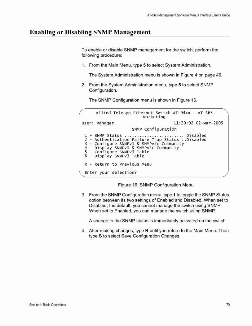
AT-S63 Management Software Menus Interface User’s Guide
Enabling or Disabling SNMP Management
To enable or disable SNMP management for the switch, perform the following procedure:
1. From the Main Menu, type 5 to select System Administration.
The System Administration menu is shown in Figure 4 on page 46.
2. From the System Administration menu, type 5 to select SNMP Configuration.
The SNMP Configuration menu is shown in Figure 16.
Figure 16. SNMP Configuration Menu
3. From the SNMP Configuration menu, type 1 to toggle the SNMP Status option between its two settings of Enabled and Disabled. When set to Disabled, the default, you cannot manage the switch using SNMP. When set to Enabled, you can manage the switch using SNMP.
A change to the SNMP status is immediately activated on the switch.
4. After making changes, type R until you return to the Main Menu. Then type S to select Save Configuration Changes.
Allied Telesyn Ethernet Switch AT-94xx - AT-S63Marketing
User: Manager 11:20:02 02-Mar-2005
SNMP Configuration
1 - SNMP Status ........................ Disabled2 - Authentication Failure Trap Status ..Disabled3 - Configure SNMPv1 & SNMPv2c Community4 - Display SNMPv1 & SNMPv2c Community5 - Configure SNMPv3 Table6 - Display SNMPv3 Table
R - Return to Previous Menu
Enter your selection?
Section I: Basic Operations 79

Chapter 4: SNMPv1 and SNMPv2c
Setting the Authentication Failure Trap
As mentioned in the SNMP Overview section in this chapter, a trap is a message sent by the switch to a management workstation or server to signal an operating event, such as when the device is reset.
An authentication failure trap is similar to other the traps. It too signals an operating event on the switch. But this trap is somewhat special because it relates to SNMP management. A switch that sends this trap could be indicating an attempt by someone to gain unauthorized management access using an SNMP application program to the switch. There are two events that can cause a switch to send this trap:
An SNMP management station attempts to access the switch using an incorrect or invalid community name.An SNMP management station tried to access a closed access community string, to which its IP address is not assigned.
Given the importance of this trap to the protection of your switch, the management software allows you to disable and enable it separately from the other traps. If you enable it, the switch will send this trap if either of the above events occur. If you disable it, the switch will not send this trap. The default is disabled.
If you enable this trap, be sure to add one or more IP addresses of trap receivers to the community strings so that the switch will know where to send the trap if it needs to.
To enable or disable the authentication trap, perform the following procedure:
1. From the Main Menu, type 5 to select System Administration.
The System Administration menu is shown in Figure 4 on page 46.
2. From the System Administration menu, type 5 to select SNMP Configuration.
The SNMP Configuration menu is shown in Figure 16 on page 79.
3. From the SNMP Configuration menu, type 2 to toggle Authentication Failure Trap Status between enabled and disabled. The default is disabled.
4. After making changes, type R until you return to the Main Menu. Then type S to select Save Configuration Changes.
80 Section I: Basic Operations
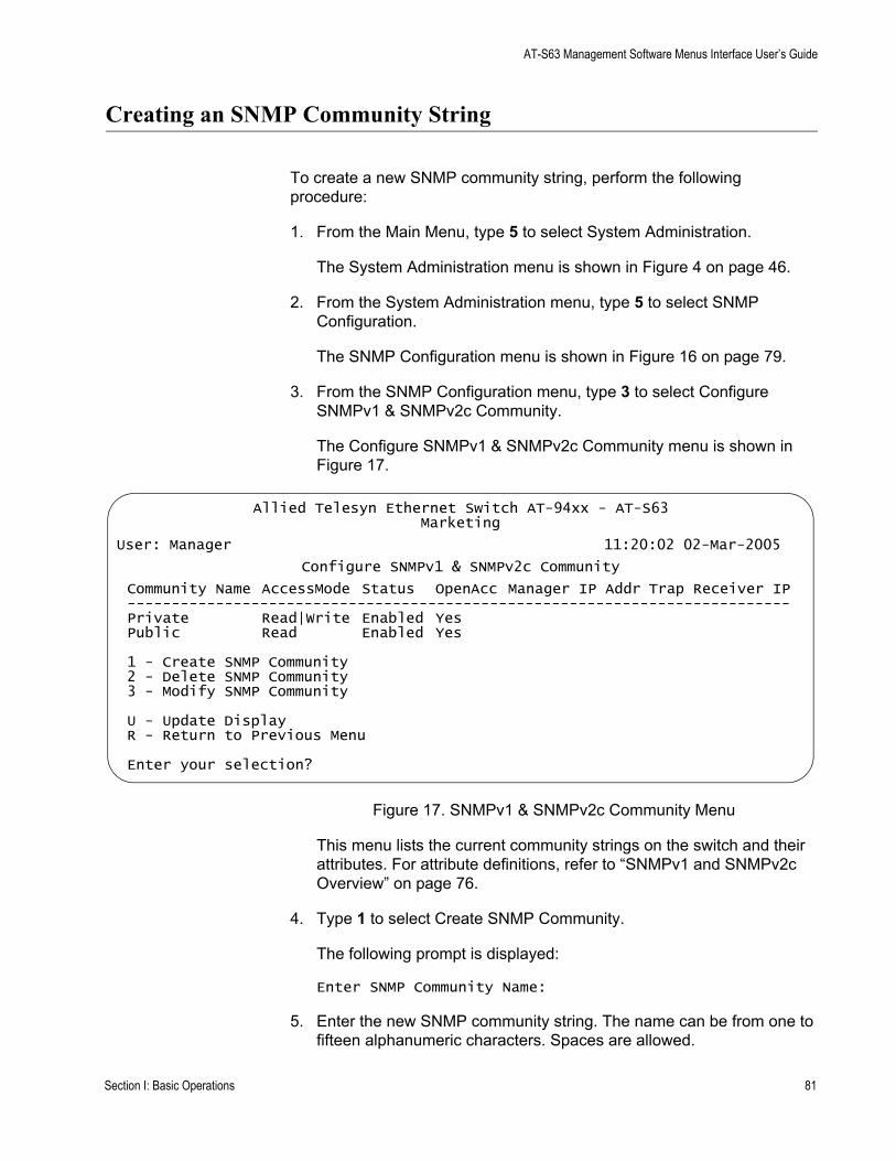
AT-S63 Management Software Menus Interface User’s Guide
Creating an SNMP Community String
To create a new SNMP community string, perform the following procedure:
1. From the Main Menu, type 5 to select System Administration.
The System Administration menu is shown in Figure 4 on page 46.
2. From the System Administration menu, type 5 to select SNMP Configuration.
The SNMP Configuration menu is shown in Figure 16 on page 79.
3. From the SNMP Configuration menu, type 3 to select Configure SNMPv1 & SNMPv2c Community.
The Configure SNMPv1 & SNMPv2c Community menu is shown in Figure 17.
Figure 17. SNMPv1 & SNMPv2c Community Menu
This menu lists the current community strings on the switch and their attributes. For attribute definitions, refer to “SNMPv1 and SNMPv2c Overview” on page 76.
4. Type 1 to select Create SNMP Community.
The following prompt is displayed:
Enter SNMP Community Name:
5. Enter the new SNMP community string. The name can be from one to fifteen alphanumeric characters. Spaces are allowed.
Allied Telesyn Ethernet Switch AT-94xx - AT-S63Marketing
User: Manager 11:20:02 02-Mar-2005
Configure SNMPv1 & SNMPv2c Community
Community Name AccessMode Status OpenAcc Manager IP Addr Trap Receiver IP---------------------------------------------------------------------------Private Read|Write Enabled YesPublic Read Enabled Yes
1 - Create SNMP Community2 - Delete SNMP Community3 - Modify SNMP Community
U - Update DisplayR - Return to Previous Menu
Enter your selection?
Section I: Basic Operations 81
Chapter 4: SNMPv1 and SNMPv2c
The following prompt is displayed:
Enter Access Mode [R-Read Only, W-Read/Write]:
6. Specify the access mode for the new SNMP community string. If you specify Read, the community string will only allow you to view the MIB objects on the switch. If you specify Read/Write, the community string will allow you to both view and change the SNMP MIB objects on the switch.
The following prompt is displayed:
Enter Open Access Status [Y-Yes, N-No]:
7. Specify the open access status. If you enter Yes, any network manager who knows the community string can use it. If you respond with No, making it closed access, only those management workstations whose IP addresses you assign to the community string can use it.
The following prompt is displayed:
Enter SNMP Manager IP Addr:
8. If in Step 7 you responded with No making this a closed community string, specify the IP address of the management workstation that can use the string. A community string can have up to eight IP addresses of management workstations. But you can assign only one to it initially with this procedure. To add additional IP addresses, refer to “Modifying a Community String” on page 84.
If you assigned the community string an access status of open, leave this field blank by pressing Return.
The following prompt is displayed:
Enter Trap Receiver IP Addr:
9. If you want the switch to send traps to a management workstation or server, enter the IP address of the node here. A community string can have up to eight IP addresses of trap receivers. But you can assign only one initially with this procedure. To add additional IP addresses, refer to “Modifying a Community String” on page 84.
If you do not want to add a IP address of a trap receiver to the community string, leave this field blank by pressing Return.
The AT-S63 management software creates the new community string and adds it to the list in the SNMP Community menu. A new community string is immediately available for use to manage the switch.
10. If desired, repeat this procedure starting with Step 4 to create additional community strings.
82 Section I: Basic Operations

AT-S63 Management Software Menus Interface User’s Guide
11. After making changes, type R until you return to the Main Menu. Then type S to select Save Configuration Changes.
Section I: Basic Operations 83
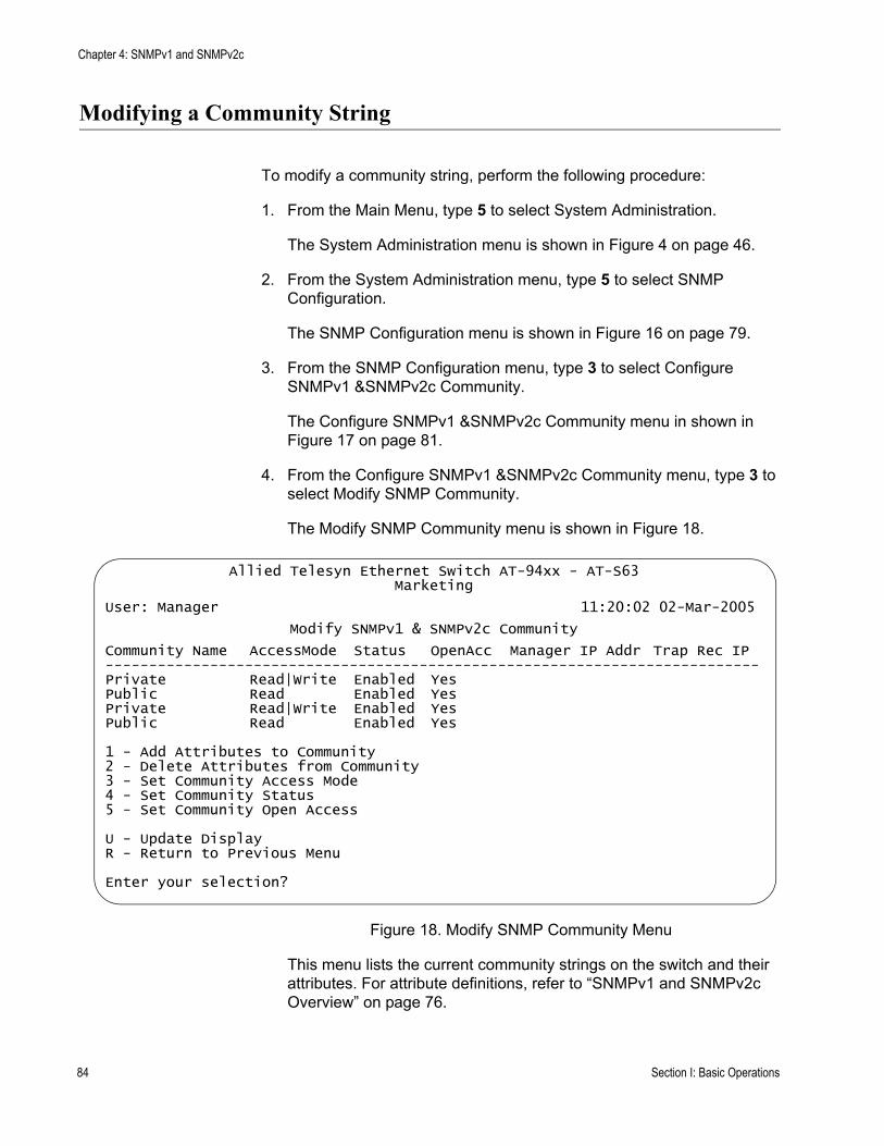
Chapter 4: SNMPv1 and SNMPv2c
Modifying a Community String
To modify a community string, perform the following procedure:
1. From the Main Menu, type 5 to select System Administration.
The System Administration menu is shown in Figure 4 on page 46.
2. From the System Administration menu, type 5 to select SNMP Configuration.
The SNMP Configuration menu is shown in Figure 16 on page 79.
3. From the SNMP Configuration menu, type 3 to select Configure SNMPv1 &SNMPv2c Community.
The Configure SNMPv1 &SNMPv2c Community menu in shown in Figure 17 on page 81.
4. From the Configure SNMPv1 &SNMPv2c Community menu, type 3 to select Modify SNMP Community.
The Modify SNMP Community menu is shown in Figure 18.
Figure 18. Modify SNMP Community Menu
This menu lists the current community strings on the switch and their attributes. For attribute definitions, refer to “SNMPv1 and SNMPv2c Overview” on page 76.
Allied Telesyn Ethernet Switch AT-94xx - AT-S63Marketing
User: Manager 11:20:02 02-Mar-2005
Modify SNMPv1 & SNMPv2c Community
Community Name AccessMode Status OpenAcc Manager IP Addr Trap Rec IP---------------------------------------------------------------------------Private Read|Write Enabled YesPublic Read Enabled YesPrivate Read|Write Enabled YesPublic Read Enabled Yes
1 - Add Attributes to Community2 - Delete Attributes from Community3 - Set Community Access Mode4 - Set Community Status5 - Set Community Open Access
U - Update DisplayR - Return to Previous Menu
Enter your selection?
84 Section I: Basic Operations

AT-S63 Management Software Menus Interface User’s Guide
The menu options are described below:
1 - Add Attributes to CommunityIf a community string has a closed access mode, you can use this selection to add new IP addresses of management workstations that can use the string. You can also use this option to add IP addresses of new trap receivers. To use this option, do the following:
a. From the Modify SNMP Community menu, type 1 to select Add Attributes to Community. The following prompt is displayed:
Enter SNMP Community Name:
b. Enter the community string you want to modify. Community strings are case sensitive. This prompt is displayed:
Enter SNMP Manager IP Addr:
c. If you are modifying a community string with a closed access mode and you want to add an IP address of a management workstation to it, enter the workstation’s IP address at the prompt. Otherwise, just press Return. A community string can have a maximum of eight IP addresses, but you can add only one at a time with this procedure. This prompt is displayed:
Enter Trap Receiver IP Addr:
d. If you want the switch to send traps to a trap receiver, enter the IP address of the receiver at this prompt. Otherwise, just press Return.
The community string is modified and the Modify SNMP Configuration menu is displayed again.
e. Repeat this procedure to modify other community strings.
f. After making changes, type R until you return to the Main Menu. Then type S to select Save Configuration Changes.
2 - Delete Attributes from CommunityUse this option to delete an IP address of a management workstation or a trap receiver from a community string. To use this option, do the following:
a. From the Modify SNMP Community menu, type 2 to select Delete Attributes from Community. The following prompt is displayed:
Enter SNMP Community Name:
b. Enter the community string you want to modify. Community strings are case sensitive. This prompt is displayed:
Section I: Basic Operations 85

Chapter 4: SNMPv1 and SNMPv2c
Enter SNMP Manager IP Addr:
c. If you want to remove the IP address of a management workstation from the community string, enter the IP address at the prompt. Otherwise, just press Return. This prompt is displayed:
Enter Trap Receiver IP Addr:
d. If you want to remove the IP address of a trap receiver from the community string, enter the IP address at the prompt. Otherwise, just press Return.
e. After making changes, type R until you return to the Main Menu. Then type S to select Save Configuration Changes.
3 - Set Community Access ModeUse this option to change a community string’s Read or Read/Write status. To use the selection, do the following:
a. From the Modify SNMP Community menu, type 3 to select Set Community Access Mode. The following prompt is displayed:
Enter SNMP Community Name:
b. Enter the community string you want to modify. Community strings are case sensitive. The following prompt is displayed:
Enter Access Mode [R-Read Only, W-Read/Write]:
c. Type R to change the string’s status to Read only, or W for Read/Write. This confirmation prompt is displayed:
Do you want to change this Community Access Mode? (Y/N): [Yes/No] ->
d. Type Y to change the string’s access mode or N to cancel the change.
e. After making changes, type R until you return to the Main Menu. Then type S to select Save Configuration Changes.
4 - Set Community StatusUse this option to enable or disable a community string. When disabled, no one can use the community string to access the switch. To use the selection, do the following:
a. From the Modify SNMP Community menu, type 4 to select Set Community Status. The following prompt is displayed:
Enter SNMP Community Name:
b. Enter the community string you want to modify. Community strings are case sensitive. The following prompt is displayed:
86 Section I: Basic Operations

AT-S63 Management Software Menus Interface User’s Guide
Enter Community Status [E-Enable, D-Disable]:
c. Type E to enable the community string or D to disable it. This confirmation prompt is displayed:
Do you want to change Community Status? (Y/N): [Yes/No] ->
d. Type Y to change the string’s status or N to cancel the change.
e. After making changes, type R until you return to the Main Menu. Then type S to select Save Configuration Changes.
5 - Set Community Open StatusUse this selection to change a string’s open status. A string with an open status can be used by any network administrator. A string with a closed status can only be used from management workstations whose IP addresses are assigned to the community string. To use the option, do the following:
a. From the Modify SNMP Community menu, type 5 to select Set Community Open Status. The following prompt is displayed:
Enter SNMP Community Name:
b. Enter the community string you want to modify. Community strings are case sensitive. The following prompt is displayed:
Enter Open Access Status [Y-Yes, N-No]:
c. Type Y to assign the string an open status or N to assign it a closed status. This confirmation prompt is displayed:
Do you want to change Open Access Status? (Y/N): [Yes/No] ->
d. Type Y to change the string’s open status or N to cancel the change.
e. After making changes, type R until you return to the Main Menu. Then type S to select Save Configuration Changes.
Section I: Basic Operations 87
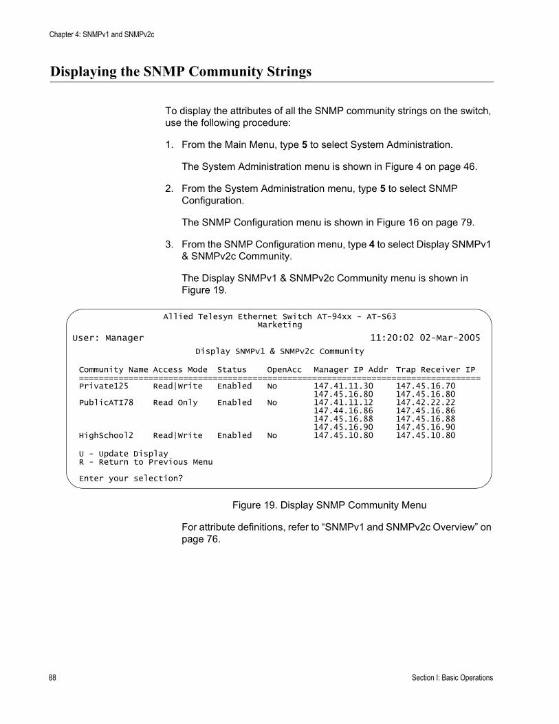
Chapter 4: SNMPv1 and SNMPv2c
Displaying the SNMP Community Strings
To display the attributes of all the SNMP community strings on the switch, use the following procedure:
1. From the Main Menu, type 5 to select System Administration.
The System Administration menu is shown in Figure 4 on page 46.
2. From the System Administration menu, type 5 to select SNMP Configuration.
The SNMP Configuration menu is shown in Figure 16 on page 79.
3. From the SNMP Configuration menu, type 4 to select Display SNMPv1 & SNMPv2c Community.
The Display SNMPv1 & SNMPv2c Community menu is shown in Figure 19.
Figure 19. Display SNMP Community Menu
For attribute definitions, refer to “SNMPv1 and SNMPv2c Overview” on page 76.
Allied Telesyn Ethernet Switch AT-94xx - AT-S63Marketing
User: Manager 11:20:02 02-Mar-2005
Display SNMPv1 & SNMPv2c Community
Community Name Access Mode Status OpenAcc Manager IP Addr Trap Receiver IP=================================================================================Private125 Read|Write Enabled No 147.41.11.30 147.45.16.70
147.45.16.80 147.45.16.80PublicATI78 Read Only Enabled No 147.41.11.12 147.42.22.22
147.44.16.86 147.45.16.86147.45.16.88 147.45.16.88147.45.16.90 147.45.16.90
HighSchool2 Read|Write Enabled No 147.45.10.80 147.45.10.80
U - Update DisplayR - Return to Previous Menu
Enter your selection?
88 Section I: Basic Operations
Chapter 5
Enhanced Stacking
This chapter explains the enhanced stacking feature. The sections in this chapter include:
“Enhanced Stacking Overview” on page 90“Setting a Switch’s Enhanced Stacking Status” on page 93“Selecting a Switch in an Enhanced Stack” on page 95“Returning to the Master Switch” on page 98“Displaying the Enhanced Stacking Status” on page 99
Section I: Basic Operations 89
Chapter 5: Enhanced Stacking
Enhanced Stacking Overview
The enhanced stacking feature can make it easier for you to manage the AT-9400 Series switches in your network. It offers the following benefits:
You can manage up to 24 switches from one local or remote management session. This eliminates the need of having to initiate a separate management session with each switch in your network. The switches can share the same IP address. This reduces the number of IP addresses that you need to assign to your network devices for remote management.Remotely managing a new switch in your network is simplified. You connect it to your network. After the switch is connected to the network, you can manage it immediately from any management station in your network.
EnhancedStacking
Guidelines
There are a few guidelines to keep in mind when implementing enhanced stacking for your network:
An enhanced stack cannot span subnets.All of the switches in an enhanced stack must use the same management VLAN. For information about Management VLANs, refer to “Specifying a Management VLAN” on page 581.A subnet can contain more than one enhanced stack. You can create different enhanced stacks within a subnet by assigning the switches to different Management VLANs. An enhanced stack must have at least one master switch.The master switch can be any switch that supports enhanced stacking, such as an AT-8000 Series switch, an AT-8400 Series switch, or an AT-9400 Series switch.You should assign the master switch an IP address and subnet mask.
NoteNo IP address is required if you intend to manage the enhanced stack solely through the RJ-45 serial terminal port on a master switch. However, remote management of a stack using Telnet, a web browser, or an SNMP application does require assigning an IP address and subnet mask to a master switch.
You must set a master switch’s stacking status to master.The enhanced stacking feature uses the IP address 172.16.16.16. Do not assign this address to any device on your subnet if you intend to use the enhanced stacking feature.
90 Section I: Basic Operations
AT-S63 Management Software Menus Interface User’s Guide
There are three basic tasks to implement this feature on your network:
You must select a switch in each subnet of your network to function as the master switch of the enhanced stack for that subnet.
The master switch can be any switch that supports enhanced stacking, such as an AT-8000 Series switch, an AT-8400 Series switch, or an AT-9400 Series switch. For networks that consist of more than one subnet, there must be at least one master switch in each subnet.
Allied Telesyn recommends that each enhanced stack have two master switches, each assigned a unique IP address. That way, should you remove one of the master switches from the network, such as for maintenance, you all still be able to remotely manage the switches in the stack using the other master switch.
You should assign each master switch a unique IP address and a subnet mask.
A master switch should have a unique IP address and a subnet mask. The other switches in an enhanced stack, referred to as slave switches, do not need an IP address.
If an enhanced stack will have more than one master switch, you must assign each master switch a unique IP address.
NoteYou can set the IP address manually or activate the BOOTP and DHCP services on a master switch and have the master switch obtain its IP information from a BOOTP or DHCP server on your network. Initially assigning an IP address or activating the BOOTP and DHCP services can only be performed through a local management session.
For instructions on how to set the IP address manually, refer to “Configuring the IP Address, Switch Name, and Other Basic Parameters” on page 46. For instructions on activating the BOOTP and DHCP services, refer to “Activating the BOOTP or DHCP Client Software” on page 49.
NoteNo IP address is required if you intend to manage the enhanced stack solely through the RJ-45 serial terminal port on a master switch. However, remote management of a stack using Telnet, a web browser, or an SNMP application does require assigning an IP address and subnet mask to a master switch.
Change the enhanced stacking status of the master switch to master.
Section I: Basic Operations 91

Chapter 5: Enhanced Stacking
This is explained in “Setting a Switch’s Enhanced Stacking Status” on page 93.
Figure 20 is an example of the enhanced stacking feature.
Figure 20. Enhanced Stacking Example
The example consists of a network of two subnets interconnected with a router. Two AT-9400 Series switches in each subnet have been selected as the master switches of their respective subnets, and each has been assigned a unique IP address.
To manage the switches of a subnet, you can start a local management session or a remote Telnet management session on one of the master switches in the subnet. You then have management access to all enhanced stacking switches in the same subnet.
FAULT
MASTER
PWR
RS-232 TERMINAL PORT
Subnet A
Subnet B
Master 2
149.32.11.16IP Address
Master 1
149.32.11.22IP Address
Master 1
149.32.09.18IP Address
Master 2
149.32.09.24IP Address
Router
FAULT
RPS
MASTER
POWER
CLASS 1LASER PRODUCT
STATUSTERMINALPORT
1 3 5 7 9 11
2 4 6 8 10 12
13 15 17 19 21 23R
14 16 18 20 22 24R
AT-9424T/SP Gigabit Ethernet Switch
1 3 5 7 9 11 13 15 17 19 21 23R
2 4 6 8 10 12 14 16 18 20 22 24R
23 24
L/A
D/C
D/C
L/A
D/C
L/A 1000 LINK / ACT
HDX / COLFDX
10/100 LINK / ACTPORT ACTIVITY
L/A
1000 LINK / ACTSFPSFP
24
SFP
23
92 Section I: Basic Operations

AT-S63 Management Software Menus Interface User’s Guide
Setting a Switch’s Enhanced Stacking Status
The enhanced stacking status of the switch can be master switch, slave switch, or unavailable. Each status is described below:
Master switch - A master switch of a stack can be used to manage all the other switches in a subnet. After you establish a local or remote management session with the master switch, you can access and manage all the switches in the subnet.A master switch must have a unique IP address. You can manually assign a master switch an IP address or activate the BOOTP and DHCP services on the switch.Slave switch - A slave switch can be remotely managed through a master switch. It does not need an IP address or subnet mask.Unavailable - A switch with an unavailable stacking status cannot be remotely managed through a master switch. A switch with this designation can be managed locally. To be managed remotely, a switch with an unavailable stacking status must be assigned a unique IP address.
NoteThe default setting for a switch is slave.
NoteYou cannot change the stacking status of a switch accessed through enhanced stacking. To change the stacking status of a switch that does not have an IP address or subnet mask, such as a slave switch, you must use a local management session. If the switch has an IP address and subnet mask, such as a master switch, you can use either a local or a Telnet management session.
To adjust a switch’s enhanced stacking status, perform the following procedure:
1. From the Main Menu, type 8 to select Enhanced Stacking.
Section I: Basic Operations 93

Chapter 5: Enhanced Stacking
The Enhanced Stacking menu is shown in Figure 21.
Figure 21. Enhanced Stacking Menu
The menu displays the current status of the switch at the end of selection “1 - Switch State.” For example, the switch’s current status in the figure above is master.
NoteItem 2, Stacking Services, is only displayed on master switches.
2. To change a switch’s stacking status, type 1 to select Switch State.
The following prompt is displayed.
Enter new setup (M/S/U) ->
3. Type M to change the switch to a master switch, S to make it a slave switch, or U to make the switch unavailable. Press Return.
A change to the status is immediately activated on the switch.
4. After making changes, type R until you return to the Main Menu. Then type S to select Save Configuration Changes.
Allied Telesyn Ethernet Switch AT-94xx - AT-S63Marketing
User: Manager 11:20:02 02-Mar-2005
Enhanced Stacking
1 - Switch State-(M)aster/(S)lave/(U)navailable.... Master2 - Stacking Services
R - Return to Previous Menu
Enter your selection?
94 Section I: Basic Operations
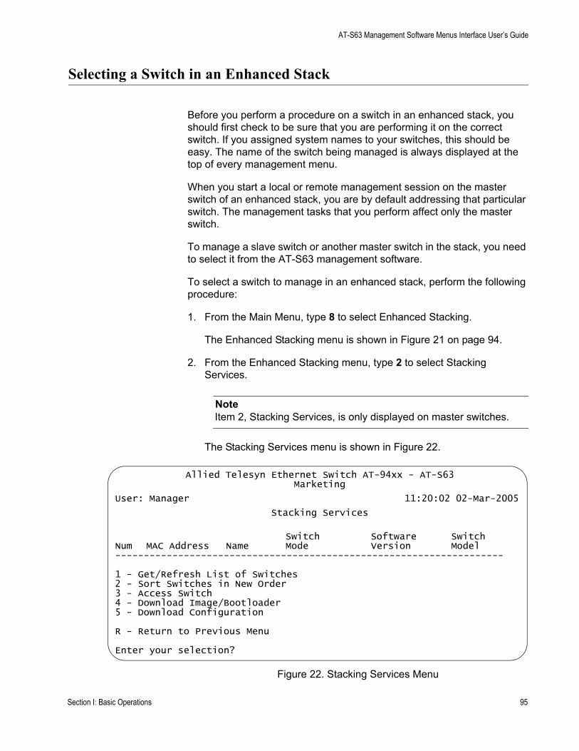
AT-S63 Management Software Menus Interface User’s Guide
Selecting a Switch in an Enhanced Stack
Before you perform a procedure on a switch in an enhanced stack, you should first check to be sure that you are performing it on the correct switch. If you assigned system names to your switches, this should be easy. The name of the switch being managed is always displayed at the top of every management menu.
When you start a local or remote management session on the master switch of an enhanced stack, you are by default addressing that particular switch. The management tasks that you perform affect only the master switch.
To manage a slave switch or another master switch in the stack, you need to select it from the AT-S63 management software.
To select a switch to manage in an enhanced stack, perform the following procedure:
1. From the Main Menu, type 8 to select Enhanced Stacking.
The Enhanced Stacking menu is shown in Figure 21 on page 94.
2. From the Enhanced Stacking menu, type 2 to select Stacking Services.
NoteItem 2, Stacking Services, is only displayed on master switches.
The Stacking Services menu is shown in Figure 22.
Figure 22. Stacking Services Menu
Allied Telesyn Ethernet Switch AT-94xx - AT-S63Marketing
User: Manager 11:20:02 02-Mar-2005
Stacking Services
Switch Software SwitchNum MAC Address Name Mode Version Model--------------------------------------------------------------------
1 - Get/Refresh List of Switches2 - Sort Switches in New Order3 - Access Switch4 - Download Image/Bootloader5 - Download Configuration
R - Return to Previous Menu
Enter your selection?
Section I: Basic Operations 95

Chapter 5: Enhanced Stacking
3. From the Stacking Services menu, type 1 to select Get/Refresh List of Switches.
The master switch polls the subnet for all slave and master switches that are a part of the enhanced stack and displays a list of the switches in the Stacking Services menu, as shown in the example in Figure 23.
Figure 23. Stacking Services Menu With List of Switches
The master switch on which you started the management session is not included in the list, nor are any switches with an enhanced stacking status of Unavailable.
By default, the switches are sorted in the menu by MAC address. You can sort the switches by name as well. To do this, select option 2, Sort Switches in New Order.
NoteItem 4, Download Image/Bootloader, downloads the AT-S63 image from a master switch to another AT-9400 Series switch in the subnet, as explained in “Downloading an AT-S63 Image File Switch to Switch” on page 212. Item 5, Download Configuration, allows you to download a configuration file from a master switch to another AT-9400 Series switch in the subnet, as explained in “Downloading a System File” on page 216.
4. To manage a new switch, type 3 to select Access Switch.
A prompt similar to the following is displayed:
Enter the switch number -> [1 to 24]
Allied Telesyn Ethernet Switch AT-94xx - AT-S63Marketing
User: Manager 11:20:02 02-Mar-2005
Stacking Services
Switch Software SwitchNum MAC Address Name Mode Version Model--------------------------------------------------------------------01 00:00:00:12:34:30 Local Users Slave S63 v1.0.0 AT-9424T/SP02 00:30:84:f3:b4:60 Engineering Slave S63 v1.0.0 AT-9424T/GB03 00:30:84:54:02:60 Finance Slave S62 v1.0.0 AT-8524M
1 - Get/Refresh List of Switches2 - Sort Switches in New Order3 - Access Switch4 - Download Image/Bootloader5 - Download Configuration
R - Return to Previous Menu
Enter your selection?
96 Section I: Basic Operations

AT-S63 Management Software Menus Interface User’s Guide
5. Type the number of the switch in the list you want to manage.
A prompt is displayed if the switch has been assigned a password.
6. Enter the appropriate username and password for the switch.
The Main Menu of the selected switch is displayed. You now can manage the switch. Any management tasks you perform effect only the selected switch.
Section I: Basic Operations 97
Chapter 5: Enhanced Stacking
Returning to the Master Switch
When you have finished managing a slave switch, return to the Main Menu of the slave switch and type Q for Quit. This returns you to the Stacking Services menu. After you see that menu, you are again addressing the master switch from which you started the management session.
You can either select another switch in the list to manage or, if you want to manage the master switch, type R twice to return to the master switch’s Main Menu.
98 Section I: Basic Operations
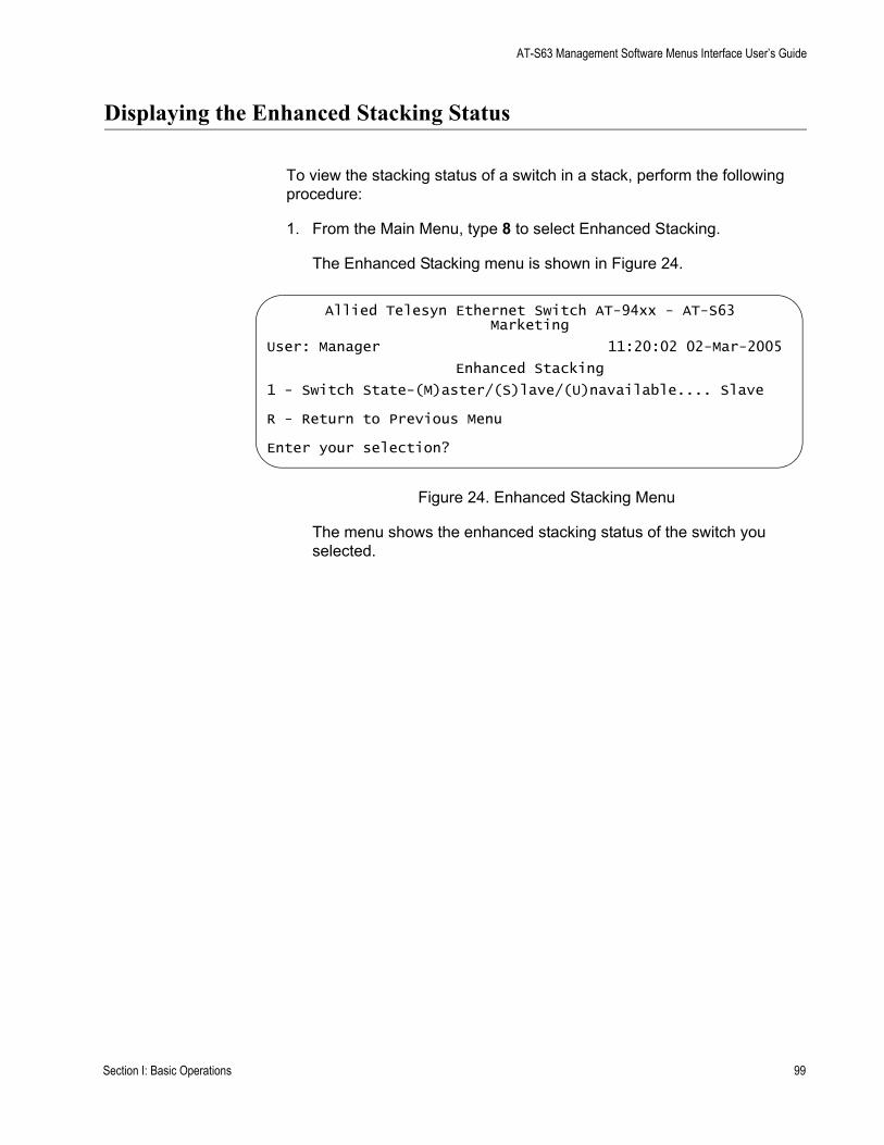
AT-S63 Management Software Menus Interface User’s Guide
Displaying the Enhanced Stacking Status
To view the stacking status of a switch in a stack, perform the following procedure:
1. From the Main Menu, type 8 to select Enhanced Stacking.
The Enhanced Stacking menu is shown in Figure 24.
Figure 24. Enhanced Stacking Menu
The menu shows the enhanced stacking status of the switch you selected.
Allied Telesyn Ethernet Switch AT-94xx - AT-S63Marketing
User: Manager 11:20:02 02-Mar-2005
Enhanced Stacking
1 - Switch State-(M)aster/(S)lave/(U)navailable.... Slave
R - Return to Previous Menu
Enter your selection?
Section I: Basic Operations 99

Chapter 5: Enhanced Stacking
100 Section I: Basic Operations
Chapter 6
Port Parameters
This chapter contains the procedures for viewing and changing the parameter settings for the individual ports on a switch, and contains the following procedures:
“Configuring Port Parameters” on page 102“Configuring Head of Line Blocking” on page 107“Configuring Flow Control and Back Pressure” on page 109“Configuring Filtering” on page 112“Setting Up Rate Limiting” on page 114“Resetting a Port” on page 116“Forcing Port Renegotiation” on page 117“Resetting the Port Configuration to the Defaults” on page 118“Displaying Port Statistics” on page 119“Clearing Port Statistics” on page 122“Displaying Port Status” on page 123
Section I: Basic Operations 101
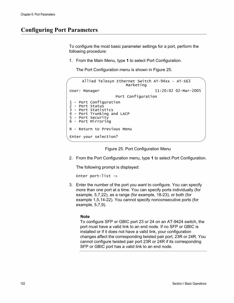
Chapter 6: Port Parameters
Configuring Port Parameters
To configure the most basic parameter settings for a port, perform the following procedure:
1. From the Main Menu, type 1 to select Port Configuration.
The Port Configuration menu is shown in Figure 25.
Figure 25. Port Configuration Menu
2. From the Port Configuration menu, type 1 to select Port Configuration.
The following prompt is displayed:
Enter port-list ->
3. Enter the number of the port you want to configure. You can specify more than one port at a time. You can specify ports individually (for example, 5,7,22), as a range (for example, 18-23), or both (for example 1,5,14-22). You cannot specify nonconsecutive ports (for example, 5,7,9).
NoteTo configure SFP or GBIC port 23 or 24 on an AT-9424 switch, the port must have a valid link to an end node. If no SFP or GBIC is installed or if it does not have a valid link, your configuration changes affect the corresponding twisted pair port, 23R or 24R. You cannot configure twisted pair port 23R or 24R if its corresponding SFP or GBIC port has a valid link to an end node.
Allied Telesyn Ethernet Switch AT-94xx - AT-S63Marketing
User: Manager 11:20:02 02-Mar-2005
Port Configuration
1 - Port Configuration2 - Port Status3 - Port Statistics4 - Port Trunking and LACP5 - Port Security6 - Port Mirroring
R - Return to Previous Menu
Enter your selection?
102 Section I: Basic Operations
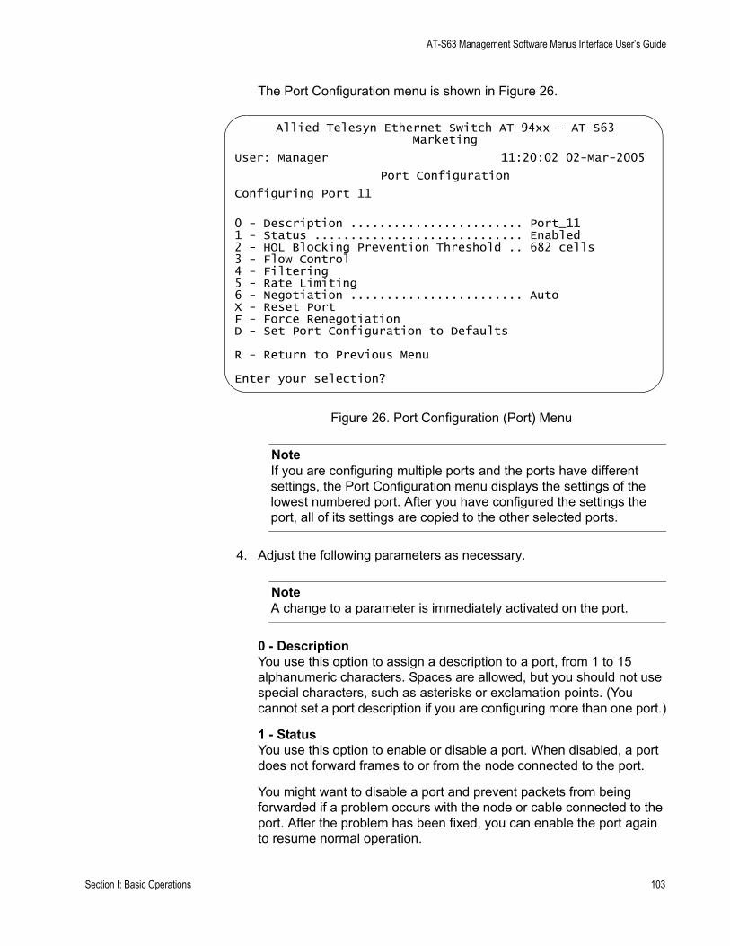
AT-S63 Management Software Menus Interface User’s Guide
The Port Configuration menu is shown in Figure 26.
Figure 26. Port Configuration (Port) Menu
NoteIf you are configuring multiple ports and the ports have different settings, the Port Configuration menu displays the settings of the lowest numbered port. After you have configured the settings the port, all of its settings are copied to the other selected ports.
4. Adjust the following parameters as necessary.
NoteA change to a parameter is immediately activated on the port.
0 - DescriptionYou use this option to assign a description to a port, from 1 to 15 alphanumeric characters. Spaces are allowed, but you should not use special characters, such as asterisks or exclamation points. (You cannot set a port description if you are configuring more than one port.)
1 - StatusYou use this option to enable or disable a port. When disabled, a port does not forward frames to or from the node connected to the port.
You might want to disable a port and prevent packets from being forwarded if a problem occurs with the node or cable connected to the port. After the problem has been fixed, you can enable the port again to resume normal operation.
Allied Telesyn Ethernet Switch AT-94xx - AT-S63Marketing
User: Manager 11:20:02 02-Mar-2005
Port Configuration
Configuring Port 11
0 - Description ........................ Port_111 - Status ............................. Enabled2 - HOL Blocking Prevention Threshold .. 682 cells3 - Flow Control4 - Filtering5 - Rate Limiting6 - Negotiation ........................ AutoX - Reset PortF - Force RenegotiationD - Set Port Configuration to Defaults
R - Return to Previous Menu
Enter your selection?
Section I: Basic Operations 103
Chapter 6: Port Parameters
You might also want to disable a port that is not being used to secure it from unauthorized connections.
Possible settings for this parameter are:
Enabled - The port receives and forwards packets. This is the default setting.
Disabled - The port does not receive or forward packets.
NoteThe procedures for implementing item 2, HOL Blocking Prevention, are described in “Configuring Head of Line Blocking” on page 107.
The procedures for item 3, Flow Control, are described in “Configuring Head of Line Blocking” on page 107.
To set up item 4, Filtering, go to “Configuring Filtering” on page 112.
Item 5, Rate Limiting, is described in “Setting Up Rate Limiting” on page 114.
6 - NegotiationYou use this option to configure a port for autonegotiation or to manually set a port’s speed and duplex mode. The default is Auto.
NoteWhen you set negotiation to Manual, items 7 (Speed), 8 (Duplex), and 9 (MDI Crossover) are displayed.
If you select Auto for autonegotiation, which is the default setting, the switch sets speed, duplex mode, and MDI crossover for the port automatically. The switch determines the highest possible common speed between the port and its end node and sets the port to that speed. This helps to ensure that the port and the end node are operating at the highest possible common speed.
Note the following items concerning the operation of autonegotiation on the switch port:
In order for a switch port to successfully autonegotiate its duplex mode with an end node, the end node should also be using autonegotiation. Otherwise, a duplex mode mismatch can occur. A switch port using autonegotiation defaults to half-duplex if it detects that the end node is not using autonegotiation. This results in a mismatch if the end node is operating at a fixed duplex mode of full-duplex.To avoid this problem, when you connect an end node with a fixed duplex mode of full-duplex to a switch port, you should disable
104 Section I: Basic Operations
AT-S63 Management Software Menus Interface User’s Guide
autonegotiation on the port and set the port’s speed and duplex mode manually.When the port is set to autonegotiate, the MDI/MDI-X setting is locked at auto-MDI/MDI-X. The switch automatically determines the correct MDI/MDI-X setting. You cannot set MDI/MDI-X manually.When autonegotiation is disabled on a port, the auto-MDI/MDI-X feature on a port is also disabled, and the port defaults to the MDI-X configuration. Consequently, if you disable autonegotiation and set a port’s speed and duplex mode manually, you might also need to set the port’s MDI/MDI-X setting as well.
NoteItems 7, 8, and 9 are not available for SFP and GBIC ports 23 and 24 which are automatically set to 1000 Mbps, full-duplex, and auto-MDI/MDIX.
7 - SpeedThis item is only available when Negotiation is set to Manual. Type 7 to toggle between two selections:
10 Mbps
100 Mbps
1000 Mbps is only available when you set selection 6, Negotiation, to Automatic.
8 - DuplexThis item is only available when Negotiation is set to Manual. The possible settings are full-duplex and half-duplex.
9 - MDI CrossoverThis item is only available when Negotiation is set to Manual.
This selection sets the wiring configuration of the port. The configuration can be MDI or MDI-X.
The twisted pair ports on the switch feature auto-MDI/MDI-X. They configure themselves automatically as MDI or MDI-X when connected to an end node. This allows you to use either a straight-through or crossover twisted pair cable when connecting any network device to a port on the switch.
When a port is using autonegotiation to set its speed and duplex mode, the only available setting for this item is Auto. The port automatically sets its MDI/MDI-X setting.
But if you disable autonegotiation on a port and set a port’s speed and duplex mode manually, the auto-MDI/MDI-X feature is also disabled. A port where autonegotiation has been disabled defaults to MDI-X.
Section I: Basic Operations 105
Chapter 6: Port Parameters
Disabling autonegotiation may require that you manually configure a port’s MDI/MDI-X setting using this option or that you use a crossover cable.
NoteWhen a transceiver is inserted into an uplink slot and a link is established, that slot becomes a primary uplink port and the corresponding backup port, 23R or 24R, automatically transitions to redundant uplink status. The speed and duplex mode of the redundant port automatically transitions to Auto-Negotiate to match the speed of the primary uplink port and you cannot configure the MDI/MDIX crossover parameter.
The final three parameters on the Port Configuration menu are:
X - Reset PortThis item resets the selected port. For more information, see “Resetting a Port” on page 116.
F - Force RenegotiationThis item prompts the port to autonegotiate with the end node. For more information, see “Forcing Port Renegotiation” on page 117.
D - Set Port Configuration to DefaultsThis item resets all port settings to the default values. For more information, see “Resetting the Port Configuration to the Defaults” on page 118.
5. After making changes, type R until you return to the Main Menu. Then type S to select Save Configuration Changes.
106 Section I: Basic Operations
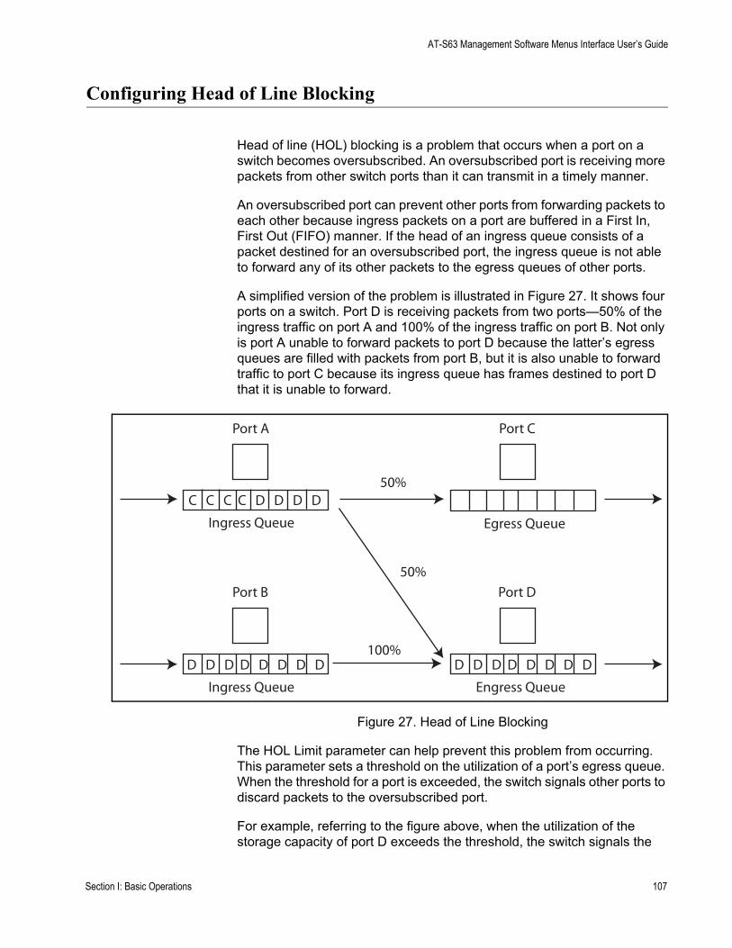
AT-S63 Management Software Menus Interface User’s Guide
Configuring Head of Line Blocking
Head of line (HOL) blocking is a problem that occurs when a port on a switch becomes oversubscribed. An oversubscribed port is receiving more packets from other switch ports than it can transmit in a timely manner.
An oversubscribed port can prevent other ports from forwarding packets to each other because ingress packets on a port are buffered in a First In, First Out (FIFO) manner. If the head of an ingress queue consists of a packet destined for an oversubscribed port, the ingress queue is not able to forward any of its other packets to the egress queues of other ports.
A simplified version of the problem is illustrated in Figure 27. It shows four ports on a switch. Port D is receiving packets from two ports—50% of the ingress traffic on port A and 100% of the ingress traffic on port B. Not only is port A unable to forward packets to port D because the latter’s egress queues are filled with packets from port B, but it is also unable to forward traffic to port C because its ingress queue has frames destined to port D that it is unable to forward.
Figure 27. Head of Line Blocking
The HOL Limit parameter can help prevent this problem from occurring. This parameter sets a threshold on the utilization of a port’s egress queue. When the threshold for a port is exceeded, the switch signals other ports to discard packets to the oversubscribed port.
For example, referring to the figure above, when the utilization of the storage capacity of port D exceeds the threshold, the switch signals the
Port A
C C C C D D D D
Ingress Queue
Port B
D D D D D D D D
Ingress Queue
Port C
Egress Queue
Port D
D D D D D D D D
Engress Queue
100%
50%
50%
Section I: Basic Operations 107
Chapter 6: Port Parameters
other ports to discard packets destined for port D. Port A drops the D packets, enabling it to once again forward packets to port C.
The number that you enter for this value represents cells. A cell is 128 bytes. The range is 0 to 8191 cells. The default is 682.
To set up head of line blocking, perform the following procedure:
1. From the Main Menu, type 1 to select Port Configuration.
The Port Configuration menu is shown in Figure 25 on page 102.
2. From the Port Configuration menu, type 1 to select Port Configuration.
The following prompt is displayed:
Enter port-list ->
3. Enter the number of the port you want to configure. To configure a range of ports, enter the first and last ports of the range, separated by a dash (for example, 4-8). You cannot specify nonconsecutive ports (for example, 5,7,9)
The Port Configuration menu is shown in Figure 26 on page 103.
4. From the Port Configuration menu, type 2 to select HOL BLocking Prevention Threshold.
The following prompt is displayed:
Enter HOL Blocking Prevention Threshold (128 byte cells) : [1 to 8191] -> 682
5. Enter the threshold in cells. A cell equals 128 bytes. The range is 1 to 8191 cells and the default is 682.
6. After making changes, type R until you return to the Main Menu. Then type S to select Save Configuration Changes.
108 Section I: Basic Operations
AT-S63 Management Software Menus Interface User’s Guide
Configuring Flow Control and Back Pressure
A switch port uses flow control to control the flow of ingress packets from its end node. Flow control applies only to ports operating in full-duplex mode.
A port using flow control issues a special frame, referred to as a PAUSE frame, as specified in the IEEE 802.3x standard, to stop the transmission of data from an end node. When a port needs to stop an end node from transmitting data, it issues this frame. The frame instructs the end node to cease transmission. The port continues to issue PAUSE frames until it is again ready to receive data from the end node.
The default setting for flow control on a switch port is disabled.
Back pressure performs much the same function as flow control. Both are used by a port to control the flow of ingress packets. Flow control applies to ports operating in full-duplex; back pressure applies to ports operating in half-duplex mode.
When a twisted pair port on the switch operating in half-duplex mode needs to stop an end node from transmitting data, it forces a collision. A collision on an Ethernet network occurs when two end nodes attempt to transmit data using the same data link at the same time. A collision causes the end nodes to stop sending data.
When a switch port needs to stop a half-duplex end node from transmitting data, it forces a collision on the data link, which stops the end node. After the switch is ready to receive data again, the switch stops forcing collisions. This is called back pressure.
The default setting for back pressure on a switch port is disabled.
To set up flow control or back pressure, perform the following procedure:
1. From the Main Menu, type 1 to select Port Configuration.
The Port Configuration menu is shown in Figure 25 on page 102.
2. From the Port Configuration menu, type 1 to select Port Configuration.
The following prompt is displayed:
Enter port-list ->
3. Enter the number of the port you want to configure. To configure a range of ports, enter the first and last ports of the range, separated by a dash (for example, 4-8). You cannot specify nonconsecutive ports (for example, 5,7,9)
Section I: Basic Operations 109
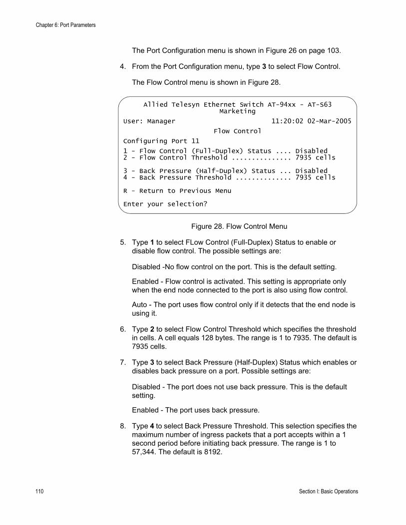
Chapter 6: Port Parameters
The Port Configuration menu is shown in Figure 26 on page 103.
4. From the Port Configuration menu, type 3 to select Flow Control.
The Flow Control menu is shown in Figure 28.
Figure 28. Flow Control Menu
5. Type 1 to select FLow Control (Full-Duplex) Status to enable or disable flow control. The possible settings are:
Disabled -No flow control on the port. This is the default setting.
Enabled - Flow control is activated. This setting is appropriate only when the end node connected to the port is also using flow control.
Auto - The port uses flow control only if it detects that the end node is using it.
6. Type 2 to select Flow Control Threshold which specifies the threshold in cells. A cell equals 128 bytes. The range is 1 to 7935. The default is 7935 cells.
7. Type 3 to select Back Pressure (Half-Duplex) Status which enables or disables back pressure on a port. Possible settings are:
Disabled - The port does not use back pressure. This is the default setting.
Enabled - The port uses back pressure.
8. Type 4 to select Back Pressure Threshold. This selection specifies the maximum number of ingress packets that a port accepts within a 1 second period before initiating back pressure. The range is 1 to 57,344. The default is 8192.
Allied Telesyn Ethernet Switch AT-94xx - AT-S63Marketing
User: Manager 11:20:02 02-Mar-2005
Flow Control
Configuring Port 11
1 - Flow Control (Full-Duplex) Status .... Disabled2 - Flow Control Threshold ............... 7935 cells
3 - Back Pressure (Half-Duplex) Status ... Disabled4 - Back Pressure Threshold .............. 7935 cells
R - Return to Previous Menu
Enter your selection?
110 Section I: Basic Operations

AT-S63 Management Software Menus Interface User’s Guide
9. After making changes, type R until you return to the Main Menu. Then type S to select Save Configuration Changes.
Section I: Basic Operations 111
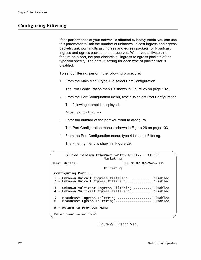
Chapter 6: Port Parameters
Configuring Filtering
If the performance of your network is affected by heavy traffic, you can use this parameter to limit the number of unknown unicast ingress and egress packets, unknown multicast ingress and egress packets, or broadcast ingress and egress packets a port receives. When you activate this feature on a port, the port discards all ingress or egress packets of the type you specify. The default setting for each type of packet filter is disabled.
To set up filtering, perform the following procedure:
1. From the Main Menu, type 1 to select Port Configuration.
The Port Configuration menu is shown in Figure 25 on page 102.
2. From the Port Configuration menu, type 1 to select Port Configuration.
The following prompt is displayed:
Enter port-list ->
3. Enter the number of the port you want to configure.
The Port Configuration menu is shown in Figure 26 on page 103.
4. From the Port Configuration menu, type 4 to select Filtering.
The Filtering menu is shown in Figure 29.
Figure 29. Filtering Menu
Allied Telesyn Ethernet Switch AT-94xx - AT-S63Marketing
User: Manager 11:20:02 02-Mar-2005
Filtering
Configuring Port 11
1 - Unknown Unicast Ingress Filtering ........... Disabled2 - Unknown Unicast Egress Filtering ............ Disabled
3 - Unknown Multicast Ingress Filtering ......... Disabled4 - Unknown Multicast Egress Filtering .......... Disabled
5 - Broadcast Ingress Filtering ................. Disabled6 - Broadcast Egress Filtering .................. Disabled
R - Return to Previous Menu
Enter your selection?
112 Section I: Basic Operations
AT-S63 Management Software Menus Interface User’s Guide
5. From the Filtering menu, type 1 to toggle Unknown Unicast Ingress Filtering between Disabled and Enabled.
6. Type 2 to toggle Unknown Unicast Egress Filtering between Disabled and Enabled.
7. Type 3 to toggle Unknown Multicast Ingress Filtering between Disabled and Enabled.
8. Type 4 to toggle Unknown Multicast Egress Filtering between Disabled and Enabled.
9. Type 5 to toggle Broadcast Ingress Filtering between Disabled and Enabled.
10. Type 6 to toggle Broadcast Egress Filtering between Disabled and Enabled.
11. After making changes, type R until you return to the Main Menu. Then type S to select Save Configuration Changes.
Section I: Basic Operations 113
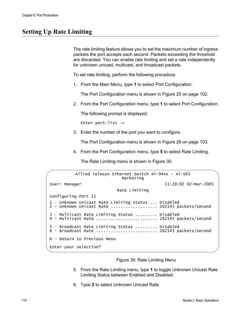
Chapter 6: Port Parameters
Setting Up Rate Limiting
The rate limiting feature allows you to set the maximum number of ingress packets the port accepts each second. Packets exceeding the threshold are discarded. You can enable rate limiting and set a rate independently for unknown unicast, multicast, and broadcast packets.
To set rate limiting, perform the following procedure:
1. From the Main Menu, type 1 to select Port Configuration.
The Port Configuration menu is shown in Figure 25 on page 102.
2. From the Port Configuration menu, type 1 to select Port Configuration.
The following prompt is displayed:
Enter port-list ->
3. Enter the number of the port you want to configure.
The Port Configuration menu is shown in Figure 26 on page 103.
4. From the Port Configuration menu, type 5 to select Rate Limiting.
The Rate Limiting menu is shown in Figure 30.
Figure 30. Rate Limiting Menu
5. From the Rate Limiting menu, type 1 to toggle Unknown Unicast Rate Limiting Status between Enabled and Disabled.
6. Type 2 to select Unknown Unicast Rate.
Allied Telesyn Ethernet Switch AT-94xx - AT-S63Marketing
User: Manager 11:20:02 02-Mar-2005
Rate Limiting
Configuring Port 11
1 - Unknown Unicast Rate Limiting Status ... Disabled2 - Unknown Unicast Rate ................... 262143 packets/second
3 - Multicast Rate Limiting Status ......... Disabled4 - Multicast Rate ......................... 262143 packets/second
5 - Broadcast Rate Limiting Status ......... Disabled6 - Broadcast Rate ......................... 262143 packets/second
R - Return to Previous Menu
Enter your selection?
114 Section I: Basic Operations
AT-S63 Management Software Menus Interface User’s Guide
The following prompt is displayed:
Enter the Rate Limit (packets/second):[0 to 262143]->
7. Enter a number for the rate limit.
8. Type 3 to toggle Multicast Rate Limiting Status between Enabled and Disabled.
9. Type 2 to select Multicast Rate.
The following prompt is displayed:
Enter the Rate Limit (packets/second):[0 to 262143]->
10. Enter a number for the rate limit.
11. Type 3 to toggle Multicast Rate Limiting Status between Enabled and Disabled.
12. Type 4 to select Multicast Rate.
The following prompt is displayed:
Enter the Rate Limit (packets/second):[0 to 262143]->
13. Enter a number for the rate limit.
14. Type 5 to toggle Broadcast Rate Limit Status between Enabled and Disabled.
15. Type 6 to select Broadcast Rate.
The following prompt is displayed:
Enter the Rate Limit (packets/second):[0 to 263143]->
16. After making changes, type R until you return to the Main Menu. Then type S to select Save Configuration Changes.
Section I: Basic Operations 115

Chapter 6: Port Parameters
Resetting a Port
Resetting a port is useful in situations where a port is having problems establishing a valid connection to its end node.
To reset a port, perform the following procedure:
1. From the Main Menu, type 1 to select Port Configuration.
The Port Configuration menu is shown in Figure 25 on page 102.
2. From the Port Configuration menu, type 1 to select Port Configuration.
The following prompt is displayed:
Enter port-list ->
3. Enter the number of the port you want to reset. To reset a range of ports, enter the first and last ports of the range, separated by a dash (for example, 4-8). You cannot specify nonconsecutive ports (for example, 5,7,9)
The Port Configuration menu is shown in Figure 26 on page 103.
4. From the Port Configuration menu, type X to select Reset Port.
116 Section I: Basic Operations
AT-S63 Management Software Menus Interface User’s Guide
Forcing Port Renegotiation
Port renegotiation prompts the port to autonegotiate with the end node. This option is useful if you believe that a port and end node are not operating at the same speed and duplex mode.
To force port renegotiation, perform the following procedure:
1. From the Main Menu, type 1 to select Port Configuration.
The Port Configuration menu is shown in Figure 25 on page 102.
2. From the Port Configuration menu, type 1 to select Port Configuration.
The following prompt is displayed:
Enter port-list ->
3. Enter the number of the port you want to reset. To reset a range of ports, enter the first and last ports of the range, separated by a dash (for example, 4-8). You cannot specify nonconsecutive ports (for example, 5,7,9)
The Port Configuration menu is shown in Figure 26 on page 103.
4. From the Port Configuration menu, type F to select Force Renegotiation.
Section I: Basic Operations 117
Chapter 6: Port Parameters
Resetting the Port Configuration to the Defaults
You can return port settings to the default values.
To reset ports to the default settings, perform the following procedure:
1. From the Main Menu, type 1 to select Port Configuration.
The Port Configuration menu is shown in Figure 25 on page 102.
2. From the Port Configuration menu, type 1 to select Port Configuration.
The following prompt is displayed:
Enter port-list ->
3. Enter the number of the port you want to reset. To reset a range of ports, enter the first and last ports of the range, separated by a dash (for example, 4-8). You cannot specify nonconsecutive ports (for example, 5,7,9)
The Port Configuration menu is shown in Figure 26 on page 103.
4. From the Port Configuration menu, type D to select Set Port Configuration to Defaults.
118 Section I: Basic Operations

AT-S63 Management Software Menus Interface User’s Guide
Displaying Port Statistics
To display Ethernet port statistics, perform the following procedure:
1. From the Main Menu, type 1 to select Port Configuration.
The Port Configuration menu is shown in Figure 25 on page 102.
2. From the Port Configuration menu, type 3 to select Port Statistics.
The Port Statistics menu is shown in Figure 31.
Figure 31. Port Statistics Menu
3. From the Port Statistics menu, type 1 to select Display Port Statistics.
The following prompt is displayed:
Enter port-list:
4. Enter the port whose statistics you want to view. You can specify more than one port at a time.
Allied Telesyn Ethernet Switch AT-94xx - AT-S63Marketing
User: Manager 11:20:02 02-Mar-2005
Port Statistics
1 - Display Port Statistics2 - Clear Port Statistics
R - Return to Previous Menu
Enter your selection?
Section I: Basic Operations 119
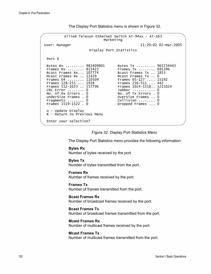
Chapter 6: Port Parameters
The Display Port Statistics menu is shown in Figure 32.
Figure 32. Display Port Statistics Menu
The Display Port Statistics menu provides the following information:
Bytes RxNumber of bytes received by the port.
Bytes TxNumber of bytes transmitted from the port.
Frames Rx Number of frames received by the port.
Frames Tx Number of frames transmitted from the port.
Bcast Frames RxNumber of broadcast frames received by the port.
Bcast Frames TxNumber of broadcast frames transmitted from the port.
Mcast Frames RxNumber of multicast frames received by the port.
Mcast Frames TxNumber of multicast frames transmitted from the port.
Allied Telesyn Ethernet Switch AT-94xx - AT-S63Marketing
User: Manager 11:20:02 02-Mar-2005
Display Port Statistics
Port 6
Bytes Rx ......... 983409801 Bytes Tx ......... 965734443Frames Rx ........ 815423 Frames Tx ........ 691396Bcast Frames Rx... 107774 Bcast Frames Tx .. 1853Mcast Frames Rx .. 11429 Mcast Frames Tx .. 0Frames 64 ........ 110509 Frames 65-127 .... 15192Frames 128-255 ... 1928 Frames 256-511 ... 442Frames 512-1023 .. 157796 Frames 1024-1518.. 1221024CRC Error ........ 0 Jabber ........... 0No. of Rx Errors . 0 No. of Tx Errors . 0UnderSize Frames . 0 OverSize Frames .. 0Fragments ........ 0 Collision ........ 0Frames 1519-1522 . 0 Dropped Frames ... 0
U - Update DisplayR - Return to Previous Menu
Enter your selection?
120 Section I: Basic Operations
AT-S63 Management Software Menus Interface User’s Guide
Frames 64Frames 65-127Frames 128-255Frames 256-511Frames 512-1023Frames 1024-1518Frames 1519-1522Number of frames transmitted from the port, grouped by size.
CRC ErrorNumber of frames with a cyclic redundancy check (CRC) error but with the proper length (64-1518 bytes) received on the port.
JabberNumber of occurrences of corrupted data or useless signals appearing on the port.
No. of Rx ErrorsNumber of receive errors.
No. of Tx ErrorsNumber of transmit errors.
Undersize FramesNumber of frames that were less than the minimum length specified by IEEE 802.3 (64 bytes including the CRC) received on the port.
Oversize Frames Number of frames exceeding the maximum specified by IEEE 802.3 (1518 bytes including the CRC) received on the port.
FragmentsNumber of undersized frames, frames with alignment errors, and frames with frame check sequence (FCS) errors (CRC errors) received on the port.
CollisionNumber of collisions that have occurred on the port.
Dropped FramesNumber of frames successfully received and buffered by the port, but discarded and not forwarded.
Section I: Basic Operations 121
Chapter 6: Port Parameters
Clearing Port Statistics
To clear the Ethernet port statistics and reset them to “0”, perform the following procedure:
1. From the Main Menu, type 1 to select Port Configuration.
The Port Configuration menu is shown in Figure 25 on page 102.
2. From the Port Configuration menu, type 3 to select Port Statistics.
The Port Statistics menu is shown in Figure 31 on page 119.
3. Type 2 to select Clear Statistics.
The statistics are reset to “0” and the statistics gathering starts again.
122 Section I: Basic Operations
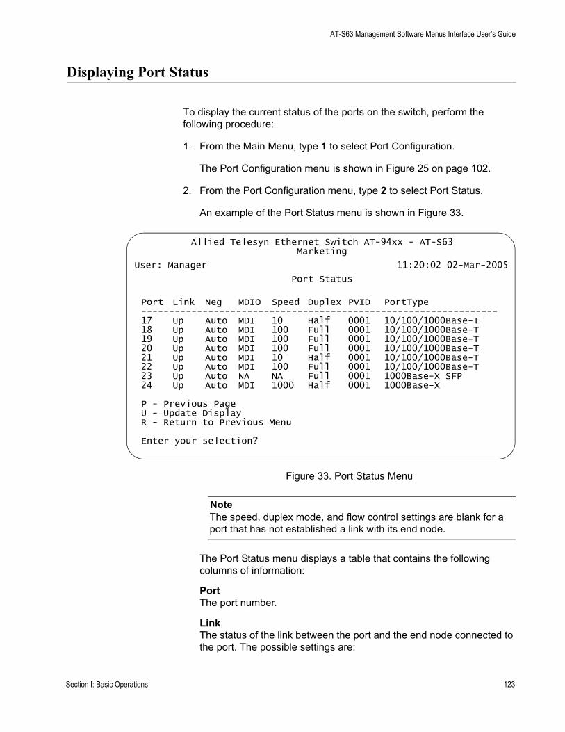
AT-S63 Management Software Menus Interface User’s Guide
Displaying Port Status
To display the current status of the ports on the switch, perform the following procedure:
1. From the Main Menu, type 1 to select Port Configuration.
The Port Configuration menu is shown in Figure 25 on page 102.
2. From the Port Configuration menu, type 2 to select Port Status.
An example of the Port Status menu is shown in Figure 33.
Figure 33. Port Status Menu
NoteThe speed, duplex mode, and flow control settings are blank for a port that has not established a link with its end node.
The Port Status menu displays a table that contains the following columns of information:
PortThe port number.
LinkThe status of the link between the port and the end node connected to the port. The possible settings are:
Allied Telesyn Ethernet Switch AT-94xx - AT-S63Marketing
User: Manager 11:20:02 02-Mar-2005
Port Status
Port Link Neg MDIO Speed Duplex PVID PortType----------------------------------------------------------------17 Up Auto MDI 10 Half 0001 10/100/1000Base-T18 Up Auto MDI 100 Full 0001 10/100/1000Base-T19 Up Auto MDI 100 Full 0001 10/100/1000Base-T20 Up Auto MDI 100 Full 0001 10/100/1000Base-T21 Up Auto MDI 10 Half 0001 10/100/1000Base-T22 Up Auto MDI 100 Full 0001 10/100/1000Base-T23 Up Auto NA NA Full 0001 1000Base-X SFP24 Up Auto MDI 1000 Half 0001 1000Base-X
P - Previous PageU - Update DisplayR - Return to Previous Menu
Enter your selection?
Section I: Basic Operations 123
Chapter 6: Port Parameters
Up - Indicates that a valid link exists between the port and the end node.
Down - Indicates that the port and the end node have not established a valid link.
NegThe status of autonegotiation on the port. Possible values are:
Auto - Indicates that the port is using autonegotiation to set operating speed and duplex mode.
Manual - Indicates that the operating speed and duplex mode have been set manually.
MDIOThe operating configuration of the port. Possible values are Auto, MDI, MDI-X. The status Auto indicates that the port automatically determines the appropriate MDI or MDI-X setting.
SpeedThe operating speed of the port. Possible values are:
10 - 10 Mbps
100 - 100 Mbps
1000 - 1000 Mbps (Gigabit Ethernet ports only)
DuplexThe duplex mode of the port. Possible values are half-duplex and full-duplex.
PVIDThe VLAN identifier (VID) of the VLAN in which the port is an untagged member. This column does not include the VIDs of the VLANs where the port is a tagged member.
Port TypeThe port type, based on the speed.
124 Section I: Basic Operations
Chapter 7
Static and LACP Port Trunks
This chapter contains the procedures for creating, modifying, and deleting static and LACP port trunks. Sections in the chapter include:
“Port Trunk Overview” on page 126“Managing Static Port Trunks” on page 136“Managing LACP Trunks” on page 143
Section I: Basic Features 125

Chapter 7: Static and LACP Port Trunks
Port Trunk Overview
A port trunk is an economical way for you to increase the bandwidth between the Ethernet switch and another networking device, such as a network server, router, workstation, or another Ethernet switch. A port trunk is a group of ports that have been grouped together to function as one logical path. A port trunk increases the bandwidth between the switch and the other network device and is useful in situations where a single physical link between the devices is insufficient to handle the traffic load.
The AT-9400 Series switch supports two types of port trunks:
Static trunksLink Aggregate Control Protocol (LACP) IEEE 802.3ad trunks
Static Port TrunkOverview
A static port trunk consists of two to eight ports on the switch that function as a single virtual link between the switch and another device. A static port trunk improves performance by distributing the traffic across multiple ports between the devices and enhances reliability by reducing the reliance on a single physical link.
A static trunk is easy to configure. You simply designate the ports on the switch that are to be in the trunk and the management software on the switch automatically groups them together. The management software also gives you control over how the traffic is to be distributed over the trunk ports, as described in “Load Distribution Methods” on page 134.
The example in Figure 34 illustrates a static port trunk of four links between two AT-9400 Series switches.
Figure 34. Static Port Trunk Example
Network equipment vendors tend to employ different techniques to implement static trunks. Consequently, a static trunk on one device might not be compatible with the same feature on a device from a different
FAULT
RPS
MASTER
POWER
CLASS 1LASER PRODUCT
STATUSTERMINALPORT
1 3 5 7 9 11
2 4 6 8 10 12
13 15 17 19 21 23R
14 16 18 20 22 24R
AT-9424T/SP Gigabit Ethernet Switch
1 3 5 7 9 11 13 15 17 19 21 23R
2 4 6 8 10 12 14 16 18 20 22 24R
23 24
L/A
D/C
D/C
L/A
D/C
L/A 1000 LINK / ACT
HDX / COLFDX
10/100 LINK / ACTPORT ACTIVITY
L/A
1000 LINK / ACTSFPSFP
24
SFP
23
126 Section I: Basic Features
AT-S63 Management Software Menus Interface User’s Guide
manufacturer. For this reason static trunks are typically employed only between devices from the same vendor. That is not to say that an Allied Telesyn layer 2 managed switch cannot form a static trunk with a device from another manufacturer; but there is the possibility that the implementations of static trunking on the two devices might not be compatible.
Also note that a static trunk does not provide for redundancy or link backup. If a port in a static trunk loses its link, the trunk’s total bandwidth is diminished. Though the traffic carried by the lost link is shifted to one of the remaining ports in the trunk, the bandwidth remains reduced until the lost link is reestablished or you reconfigure the trunk by adding another port to it.
Static Port Trunk Guidelines
Following are the guidelines for creating a static trunk:
Allied Telesyn recommends using static port trunks between Allied Telesyn networking devices to ensure compatibility. While an Allied Telesyn device might be able to form a static trunk with a device from another equipment vendor, there is the possibility that the implementation of this feature on the two devices might not be compatible, resulting in undesired switch behavior.A static trunk can contain up to eight ports.The ports of a static trunk must be of the same medium type. They can be all twisted pair ports or all fiber optic ports.The ports of a trunk can be either consecutive (for example Ports 5-9) or nonconsecutive (for example, ports 4, 8, 11, 20).Before creating a port trunk, examine the speed, duplex mode, flow control, and back pressure settings of the lowest number port that will be in the trunk. Verify that its settings are correct for the device to which the trunk will be connected. When you create a static port trunk, the management software copies the current settings of the lowest numbered port in the trunk to the other ports, because all ports in a static trunk must have the same settings. For example, if you create a port trunk consisting of ports 5 to 8, the parameter settings for port 5 are copied to ports 6, 7, and 8 so that all the ports of the trunk have the same settings.After you have created a port trunk, do not change the speed, duplex mode, flow control, or back pressure of any port in the trunk without making the same change to the other ports.A port can belong to only one static trunk at a time.A port cannot be a member of a static trunk and an LACP trunk at the same time.The switch can support up to six static trunks when LACP is disabled and three static trunks when LACP is enabled.
Section I: Basic Features 127
Chapter 7: Static and LACP Port Trunks
The ports of a static trunk must be untagged members of the same VLAN. A trunk cannot consist of untagged ports from different VLANs.The switch selects the lowest numbered port in the trunk to handle broadcast packets and packets of unknown destination. For example, a trunk of ports 11 to 15 would use port 11 for broadcast packets.
LACP TrunkOverview
An LACP (Link Aggregation Control Protocol) trunk is another type of port trunk. It performs the same function as a static trunk. It increases the bandwidth between two network devices by distributing the traffic load over multiple physical links.
The advantage of an LACP trunk over a static port trunk is its flexibility. While implementations of static trunking tend to be vendor specific, the AT-9400 Series implementation of LACP is compliant with the IEEE 802.3ad standard. This makes it interoperable with equipment from other vendors that also comply with the standard. Therefore, you can create a trunk between an Allied Telesyn device and networking devices from other manufacturers.
Another advantage is that ports in an LACP trunk can function in a standby mode. This adds redundancy and resiliency to the trunk. If a link in a static trunk goes down, the overall bandwidth of the trunk is reduced and restoring it requires reestablishing the link or manually modifying the trunk by adding another port to it. In contrast, an LACP trunk can activate ports in a standby mode when an active link fails. The automatic activation of standby ports allows the switch to maintain the maximum possible bandwidth of the trunk.
For example, assume you create an LACP trunk of ports 11 to 20 on a switch and the switch is using ports 11 to 18 as the active ports and ports 19 and 20 as reserve. If an active port loses its link, the switch automatically activates one of the two reserve ports to maintain maximum bandwidth of the trunk.
The main component of an LACP trunk is an aggregator. An aggregator is a group of ports on the switch. The ports in an aggregator are further grouped into one or more trunks, referred to as aggregate trunks.
An aggregate trunk can consist of any number of ports on a switch, but only a maximum of eight ports can be active at a time. If an aggregate trunk contains more ports than can be active at one time, the extra ports are placed in a standby mode. Ports in the standby mode do not pass network traffic, but they do transmit and accept LACP data unit (LACPDU) packets, which the switch uses to search for LACP-compliant devices.
Only ports on a switch that are part of an aggregator transmit LACPDU packets. If a switch port that is part of an aggregator does not receive LACPDU packets from its corresponding port on the other device, it assumes that the other port is not part of an LACP trunk. So instead it functions as a normal Ethernet port by forwarding network traffic.
128 Section I: Basic Features

AT-S63 Management Software Menus Interface User’s Guide
However, it does continue to send LACPDU packets. If it begins to receive LACPDU packets, it automatically transitions to an active or standby mode as part of an aggregate trunk.
If a switch is to support more than one aggregate trunk, it may be necessary to place each trunk in a separate aggregator, while in other cases you may be able to create just one aggregator and let the switch discern the individual aggregate trunks for you, automatically. The determining factor is whether the trunks are going to the same or different devices. If the trunks are going to the same device, you need to create a different aggregator for each trunk. If they are going to different devices, then you can create just one aggregator and the switch can differentiate the aggregate trunks itself.
Here are a two examples. Figure 35 illustrates an AT-9400 Series switch with two LACP trunks, each containing three links. Because both aggregate trunks go to the same 802.3ad-compliant device, in this case another Fast Ethernet switch, each trunk requires a separate aggregator.
Figure 35. Example of Multiple Aggregators for Multiple Aggregate Trunks
Here is how the example looks in a table format.
AT-9400 Series Switch
802.3ad-compliant Device
Aggregate Trunksin Separate Aggregators
Ports 1 - 3in Aggregator 1
Ports 12 -14in Aggregator 2
Ethernet Switch
FAULT
RPS
MASTER
POWER
CLASS 1LASER PRODUCT
STATUSTERMINALPORT
1 3 5 7 9 11
2 4 6 8 10 12
13 15 17 19 21 23R
14 16 18 20 22 24R
AT-9424T/SP Gigabit Ethernet Switch
1 3 5 7 9 11 13 15 17 19 21 23R
2 4 6 8 10 12 14 16 18 20 22 24R
23 24
L/A
D/C
D/C
L/A
D/C
L/A 1000 LINK / ACT
HDX / COLFDX
10/100 LINK / ACTPORT ACTIVITY
L/A
1000 LINK / ACTSFPSFP
24
SFP
23
LINK
MODE
LINK
MODE
FAULT
RPS
MASTER
PWR
MODE STATUS
AT-8524M Fast Ethernet Switch
Aggregator Description
Aggregator Ports
Aggregate Trunk Ports
Aggregator 1 1-3 1-3
Section I: Basic Features 129
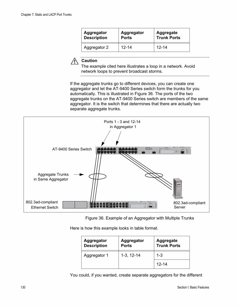
Chapter 7: Static and LACP Port Trunks
CautionThe example cited here illustrates a loop in a network. Avoid network loops to prevent broadcast storms.
If the aggregate trunks go to different devices, you can create one aggregator and let the AT-9400 Series switch form the trunks for you automatically. This is illustrated in Figure 36. The ports of the two aggregate trunks on the AT-9400 Series switch are members of the same aggregator. It is the switch that determines that there are actually two separate aggregate trunks.
Figure 36. Example of an Aggregator with Multiple Trunks
Here is how this example looks in table format.
You could, if you wanted, create separate aggregators for the different
Aggregator 2 12-14 12-14
Aggregator Description
Aggregator Ports
Aggregate Trunk Ports
AT-9400 Series Switch
802.3ad-compliantEthernet Switch
Aggregate Trunksin Same Aggregator
Ports 1 - 3 and 12-14in Aggregator 1
802.3ad-compliantServer
FAULT
RPS
MASTER
POWER
CLASS 1LASER PRODUCT
STATUSTERMINALPORT
1 3 5 7 9 11
2 4 6 8 10 12
13 15 17 19 21 23R
14 16 18 20 22 24R
AT-9424T/SP Gigabit Ethernet Switch
1 3 5 7 9 11 13 15 17 19 21 23R
2 4 6 8 10 12 14 16 18 20 22 24R
23 24
L/A
D/C
D/C
L/A
D/C
L/A 1000 LINK / ACT
HDX / COLFDX
10/100 LINK / ACTPORT ACTIVITY
L/A
1000 LINK / ACTSFPSFP
24
SFP
23
LINK
MODE
LINK
MODE
FAULT
RPS
MASTER
PWR
MODE STATUS
AT-8524M Fast Ethernet Switch
Aggregator Description
Aggregator Ports
Aggregate Trunk Ports
Aggregator 1 1-3, 12-14 1-3
12-14
130 Section I: Basic Features
AT-S63 Management Software Menus Interface User’s Guide
aggregate trunks in the example above. But letting the switch make the determination for you whenever possible saves time later if you physically reassign ports to a different trunk connected to another device.
LACP System Priority
It is possible for two devices interconnected by an aggregate trunk to encounter a conflict when they form a trunk. For example, the two devices might not support the same number of active ports in an aggregate trunk or might not agree on which ports are to be active and which are to be in standby.
If a conflict does occur, the two devices need a mechanism for resolving the problem, a means by which they can decide whose LACP settings are to take precedence. That is the function of the system LACP priority value. A hexadecimal value of from 1 to FFFF, this parameter is used whenever the devices encounter a conflict creating a trunk. The lower the number, the higher the priority. The settings on the device with the higher priority take precedence over the settings on the other device. If both devices have the same system LACP priority value, the settings on the switch with the lowest MAC address take precedence.
This parameter can prove useful when connecting an aggregate trunk between an AT-9400 Series switch and another 802.3ad-compliant device that does not have the same LACP trunking capabilities. If the other device’s capability is less than that of the AT-9400 Series switch, you should give that device the higher priority so that its settings are used by both devices when forming the trunk.
For example, an aggregate trunk of six links between an AT-9400 Series switch and an 802.3ad-compliant device that supported up to four active links at one time could possibly result in a conflict. The AT-9400 Series switch would try to use all six links as active, because it can handle up to eight active links in a trunk at one time, while the other device would want to use only four ports as active. By giving the other 802.3ad device the higher priority, the conflict is avoided because the AT-9400 Series switch uses only four active links. The other ports remain in standby mode.
Adminkey Parameter
The adminkey is a hexadecimal value from 1 to FFFF that identifies an aggregator. Each aggregator on a switch must have a unique adminkey. The adminkey is limited to a switch. Two aggregators on different switches can have the same adminkey without generating a conflict.
LACP Port Priority Parameter
The switch uses this parameter to determine which ports are to be active and which are to be in the standby mode in situations where the number of ports in the aggregate trunk exceeds the highest allowed number of active
Section I: Basic Features 131
Chapter 7: Static and LACP Port Trunks
ports. This parameter can be adjusted on each port and is a hexadecimal value in a range of 1 to FFFF. The lower the number, the higher the priority. Ports with the highest priorities are designated as the active ports in an aggregate trunk.
For example, if both 802.3ad-compliant devices support up to eight active ports and there are a total of ten ports in the trunk, the eight ports with the lowest priority settings are designated as the active ports, and the others are placed in standby mode. If an active link goes down on a active port, the standby port with the highest priority is automatically activated to take its place.
The default value of a port’s priority number is equal to its port number in hexadecimal. For example, the default values for ports 2 and 11 are 0002 and 000B, respectively.
The selection of the active links in an aggregate trunk is dynamic. It changes as links are added, removed, lost or reestablished. For example, if an active port loses its link and is replaced by another port in the standby mode, the reestablishment of the link on the originally active port causes it to return to the active state by virtue of its having a higher priority, while the port that replaced it is returned to the standby mode.
In the unusual event that you set this parameter to the same value for some or all of the ports of an aggregate trunk, the selection of active ports is based on port numbering. The lower the port number, the higher the priority.
Two conditions must be met in order for a port that is a member of an aggregate trunk to function in the standby mode. First, the number of ports in the trunk must exceed the highest allowed number of active ports and, second, the port must be receiving LACPDU packets from the other device. A port functioning in the standby mode does not forward network traffic, but it does continue to send LACPDU packets. If a port that is part of an aggregator does not receive LACPDU packets, it functions as a normal Ethernet port and forwards network packets along with LACPDU packets.
Load Distribution Methods
The load distribution method determines the manner in which the switch distributes the traffic across the active ports of an aggregate trunk. The method is assigned to an aggregator and applies to all aggregate trunks within it. If you want to assign different load distribution methods to different aggregate trunks, you must create a separate aggregator for each trunk. For further information, refer to “Load Distribution Methods” on page 134.
132 Section I: Basic Features
AT-S63 Management Software Menus Interface User’s Guide
LACP Trunk Guidelines
Following are the guidelines for creating aggregators:
LACP must be activated on both the switch and the other device.The other device must be 802.3ad-compliant.An aggregator can consist of any number of ports.The AT-9400 Series switch supports up to eight active ports in an aggregate trunk at a time.The switch supports a maximum of three aggregate trunks.The ports of an aggregate trunk must be of the same medium type: all twisted pair ports or all fiber optic ports.The ports of a trunk can be consecutive (for example ports 5-9) or nonconsecutive (for example, ports 4, 8, 11, 20).A port can belong to only one aggregator at a time.A port cannot be a member of an aggregator and a static trunk at the same time.The ports of an aggregate trunk must be untagged members of the same VLAN. (The switch’s management software does not return an error message if you create an aggregator with ports that are members of different untagged VLANs. However, it does not add the ports to the aggregate trunk when establishing the trunk.)10/100Base-TX twisted pair ports must be set to Auto-Negotiation or 100 Mbps, full-duplex mode. LACP trunking is not supported in half-duplex mode.100Base-FX fiber optic ports must be set to full-duplex mode.You can create an aggregate trunk including transceivers with 1000Base-X fiber optic ports. Only those ports that are members of an aggregator transmit LACPDU packets.The load distribution method is applied at the aggregator level. If you want aggregate trunks to have different load distribution methods, you must create a separate aggregator for each trunk. For further information, refer to “Load Distribution Methods” on page 134.A port that is a member of an aggregator functions as part of an aggregate trunk only if it receives LACPDU packets from the remote device. If it does not receive LACPDU packets, it functions as a regular Ethernet port, forwarding network traffic while also continuing to transmit LACPDU packets.The port with the highest priority in an aggregate trunk carries broadcast packets and packets with an unknown destination.Prior to creating an aggregate trunk between an AT-9400 Series switch and another vendor’s device, refer to the vendor’s documentation to
Section I: Basic Features 133
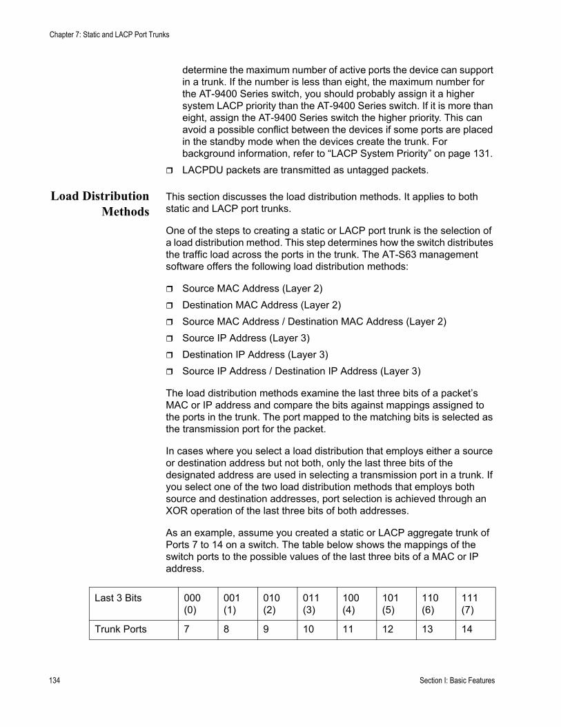
Chapter 7: Static and LACP Port Trunks
determine the maximum number of active ports the device can support in a trunk. If the number is less than eight, the maximum number for the AT-9400 Series switch, you should probably assign it a higher system LACP priority than the AT-9400 Series switch. If it is more than eight, assign the AT-9400 Series switch the higher priority. This can avoid a possible conflict between the devices if some ports are placed in the standby mode when the devices create the trunk. For background information, refer to “LACP System Priority” on page 131. LACPDU packets are transmitted as untagged packets.
Load DistributionMethods
This section discusses the load distribution methods. It applies to both static and LACP port trunks.
One of the steps to creating a static or LACP port trunk is the selection of a load distribution method. This step determines how the switch distributes the traffic load across the ports in the trunk. The AT-S63 management software offers the following load distribution methods:
Source MAC Address (Layer 2)Destination MAC Address (Layer 2)Source MAC Address / Destination MAC Address (Layer 2)Source IP Address (Layer 3)Destination IP Address (Layer 3)Source IP Address / Destination IP Address (Layer 3)
The load distribution methods examine the last three bits of a packet’s MAC or IP address and compare the bits against mappings assigned to the ports in the trunk. The port mapped to the matching bits is selected as the transmission port for the packet.
In cases where you select a load distribution that employs either a source or destination address but not both, only the last three bits of the designated address are used in selecting a transmission port in a trunk. If you select one of the two load distribution methods that employs both source and destination addresses, port selection is achieved through an XOR operation of the last three bits of both addresses.
As an example, assume you created a static or LACP aggregate trunk of Ports 7 to 14 on a switch. The table below shows the mappings of the switch ports to the possible values of the last three bits of a MAC or IP address.
Last 3 Bits 000(0)
001(1)
010(2)
011(3)
100(4)
101(5)
110(6)
111(7)
Trunk Ports 7 8 9 10 11 12 13 14
134 Section I: Basic Features

AT-S63 Management Software Menus Interface User’s Guide
Assume you selected source MAC address as the load distribution method and that the switch needed to transmit over the trunk a packet with a source MAC address that ended in 9. The binary equivalent of 9 is 1001, making the last three bits of the address 001. An examination of the table above indicates that the switch would use Port 8 to transmit the frame because that port is mapped to the matching bits.
The same method is used for the two load distribution methods that employ both the source and destination addresses. Only here the last three bits of both addresses are combined by an XOR process to derive a single value which is then compared against the mappings of the bits to ports. The XOR rules are as follows:
0 XOR 0 = 00 XOR 1 = 11 XOR 0 = 11 XOR 1 = 0
As an example, assume that you had selected source and destination MAC addresses for the load distribution method in our previous example, and that a packet for transmission over the trunk had a source MAC address that ended in 9 and a destination address that ended in 3. The binary values would be:
9 = 10013 = 0011
Applying the XOR rules above on the last three bits would result in 010, or 2. A examination of the table above shows that the packet would be transmitted from port 9.
Port trunk mappings on an AT-9400 Series switch can consist of up to eight ports. This corresponds to the maximum number of ports allowed in a static trunk and the maximum number of active ports in an LACP trunk. (Inactive ports in an LACP trunk are not applied to the mappings until they transition to the active status.)
You can assign different load distribution methods to different static trunks on the same switch. The same is true for LACP aggregators. However, it should be noted that all aggregate trunks within an LACP aggregator must use the same load distribution method.
The load distribution methods assume that the final three bits of the source and/or destination addresses of the packets from the network nodes are varied enough to support adequate distribution of the packets over the trunk ports. A lack of variation can result in one or more ports in a trunk being used more than others, with the potential loss of a trunk’s efficiency and performance.
Section I: Basic Features 135

Chapter 7: Static and LACP Port Trunks
Managing Static Port Trunks
The following procedures explain how to create, modify, and delete static port trunks:
“Creating a Static Port Trunk,” next“Modifying a Static Port Trunk” on page 139“Deleting a Static Port Trunk” on page 141
For background information, refer to “Static Port Trunk Overview” on page 126.
Creating a StaticPort Trunk
This section contains the procedure for creating a static port trunk on a switch. Be sure to review the guidelines in “Port Trunk Overview” on page 126 before performing the procedure.
CautionDo not connect the cables to the trunk ports on the switches until after you have configured the trunk with the management software. Connecting the cables before configuring the software will create a loop in your network topology. Data loops can result in broadcast storms and poor network performance.
NoteBefore creating a port trunk, examine the speed, duplex mode, and flow control settings of the lowest numbered port that will be a part of the trunk. Check to be sure that the settings are correct for the end node to which the trunk will be connected. When you create the trunk, the AT-S63 management software copies the settings of the lowest numbered port in the trunk to the other ports so that all the settings are the same.
You should also check to be sure that the ports are untagged members of the same VLAN. You cannot create a trunk of ports that are untagged members of different VLANs.
To create a port trunk, perform the following procedure:
1. From the Main Menu, type 1 to select Port Configuration.
The Port Configuration menu is shown in Figure 25 on page 102.
2. From the Port Configuration menu, type 4 to select Port Trunking and LACP.
136 Section I: Basic Features
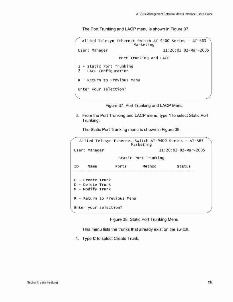
AT-S63 Management Software Menus Interface User’s Guide
The Port Trunking and LACP menu is shown in Figure 37.
Figure 37. Port Trunking and LACP Menu
3. From the Port Trunking and LACP menu, type 1 to select Static Port Trunking.
The Static Port Trunking menu is shown in Figure 38.
Figure 38. Static Port Trunking Menu
This menu lists the trunks that already exist on the switch.
4. Type C to select Create Trunk.
Allied Telesyn Ethernet Switch AT-9400 Series - AT-S63Marketing
User: Manager 11:20:02 02-Mar-2005
Port Trunking and LACP
1 - Static Port Trunking2 - LACP Configuration
R - Return to Previous Menu
Enter your selection?
Allied Telesyn Ethernet Switch AT-9400 Series - AT-S63Marketing
User: Manager 11:20:02 02-Mar-2005
Static Port Trunking
ID Name Ports Method Status----------------------------------------------------
C - Create TrunkD - Delete TrunkM - Modify Trunk
R - Return to Previous Menu
Enter your selection?
Section I: Basic Features 137
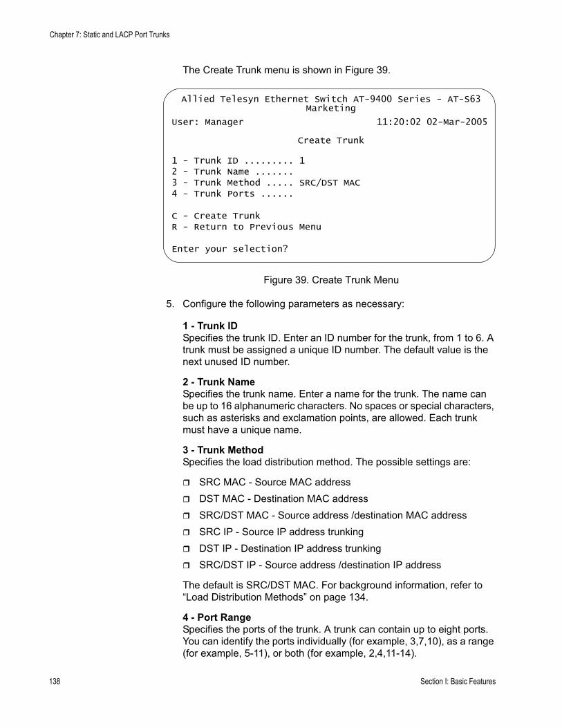
Chapter 7: Static and LACP Port Trunks
The Create Trunk menu is shown in Figure 39.
Figure 39. Create Trunk Menu
5. Configure the following parameters as necessary:
1 - Trunk IDSpecifies the trunk ID. Enter an ID number for the trunk, from 1 to 6. A trunk must be assigned a unique ID number. The default value is the next unused ID number.
2 - Trunk NameSpecifies the trunk name. Enter a name for the trunk. The name can be up to 16 alphanumeric characters. No spaces or special characters, such as asterisks and exclamation points, are allowed. Each trunk must have a unique name.
3 - Trunk MethodSpecifies the load distribution method. The possible settings are:
SRC MAC - Source MAC addressDST MAC - Destination MAC addressSRC/DST MAC - Source address /destination MAC address SRC IP - Source IP address trunkingDST IP - Destination IP address trunkingSRC/DST IP - Source address /destination IP address
The default is SRC/DST MAC. For background information, refer to “Load Distribution Methods” on page 134.
4 - Port RangeSpecifies the ports of the trunk. A trunk can contain up to eight ports. You can identify the ports individually (for example, 3,7,10), as a range (for example, 5-11), or both (for example, 2,4,11-14).
Allied Telesyn Ethernet Switch AT-9400 Series - AT-S63Marketing
User: Manager 11:20:02 02-Mar-2005
Create Trunk
1 - Trunk ID ......... 12 - Trunk Name ....... 3 - Trunk Method ..... SRC/DST MAC4 - Trunk Ports ......
C - Create TrunkR - Return to Previous Menu
Enter your selection?
138 Section I: Basic Features
AT-S63 Management Software Menus Interface User’s Guide
6. Type C to select Create Trunk.
The port trunk is now active on the switch.
7. After making changes, type R until you return to the Main Menu. Then type S to select Save Configuration Changes.
8. Configure the ports on the remote switch for port trunking.
9. Connect the cables to the ports of the trunk on the switch.
The port trunk is ready for network operations.
Modifying aStatic Port Trunk
This section contains the procedure for modifying a static port trunk on the switch. Be sure to review the guidelines in “Static Port Trunk Guidelines” on page 127 before performing the procedure.
CautionIf you will be adding or removing ports from the trunk, you should disconnect all data cables from the ports of the trunk on the switch before performing the procedure. Adding or removing ports from a static port trunk without first disconnecting the cables may result in loops in your network topology, which can result in broadcast storms and poor network performance.
Note the following before performing this procedure:
If you are adding a port and the port will be the lowest numbered port in the trunk, its parameter settings will overwrite the settings of the existing ports in the trunk. Therefore, you should check to see if its settings are appropriate prior to adding it.If you are adding a port and the port will not be the lowest numbered port in the trunk, its settings will be changed to match the settings of the existing ports in the trunk.If you are adding a port to a static trunk, you should check to be sure that the new port is an untagged member of the same VLAN as the other trunk ports. A trunk cannot contain ports that are untagged members of different VLANs.
To modify a port trunk, perform the following procedure:
1. From the Main Menu, type 1 to select Port Configuration.
The Port Configuration menu is shown in Figure 25 on page 102.
2. From the Port Configuration menu, type 4 to select Port Trunking and LACP.
The Port Trunking and LACP menu is shown in Figure 37 on page 137.
Section I: Basic Features 139
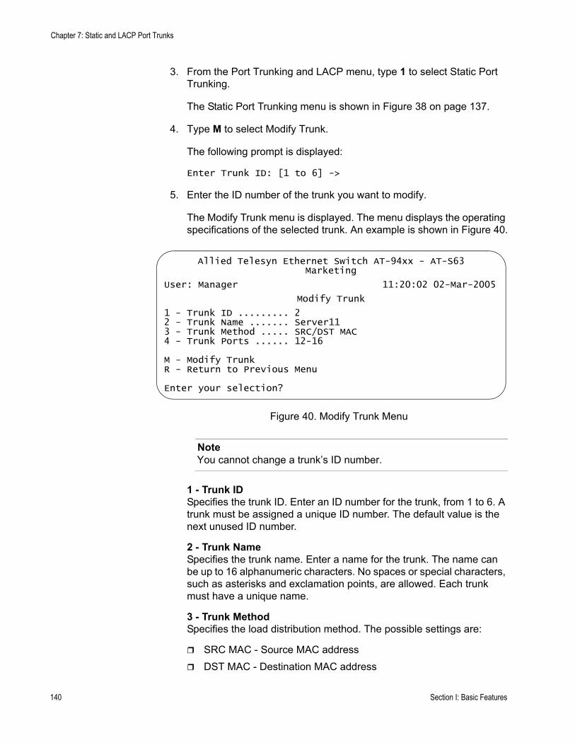
Chapter 7: Static and LACP Port Trunks
3. From the Port Trunking and LACP menu, type 1 to select Static Port Trunking.
The Static Port Trunking menu is shown in Figure 38 on page 137.
4. Type M to select Modify Trunk.
The following prompt is displayed:
Enter Trunk ID: [1 to 6] ->
5. Enter the ID number of the trunk you want to modify.
The Modify Trunk menu is displayed. The menu displays the operating specifications of the selected trunk. An example is shown in Figure 40.
Figure 40. Modify Trunk Menu
NoteYou cannot change a trunk’s ID number.
1 - Trunk IDSpecifies the trunk ID. Enter an ID number for the trunk, from 1 to 6. A trunk must be assigned a unique ID number. The default value is the next unused ID number.
2 - Trunk NameSpecifies the trunk name. Enter a name for the trunk. The name can be up to 16 alphanumeric characters. No spaces or special characters, such as asterisks and exclamation points, are allowed. Each trunk must have a unique name.
3 - Trunk MethodSpecifies the load distribution method. The possible settings are:
SRC MAC - Source MAC addressDST MAC - Destination MAC address
Allied Telesyn Ethernet Switch AT-94xx - AT-S63Marketing
User: Manager 11:20:02 02-Mar-2005
Modify Trunk
1 - Trunk ID ......... 22 - Trunk Name ....... Server113 - Trunk Method ..... SRC/DST MAC4 - Trunk Ports ...... 12-16
M - Modify TrunkR - Return to Previous Menu
Enter your selection?
140 Section I: Basic Features
AT-S63 Management Software Menus Interface User’s Guide
SRC/DST MAC - Source address /destination MAC address SRC IP - Source IP address trunkingDST IP - Destination IP address trunkingSRC/DST IP - Source address /destination IP address
The default is SRC/DST MAC. For background information, refer to “Load Distribution Methods” on page 134.
4 - Port RangeSpecifies the ports of the trunk. A trunk can contain up to eight ports. You can identify the ports individually (for example, 3,7,10), as a range (for example, 5-11), or both (for example, 2,4,11-14).
6. Type M to select Modify Trunk.
The modifications to the port trunk are activated on the switch.
7. After making changes, type R until you return to the Main Menu. Then type S to select Save Configuration Changes.
8. Reconnect the cables to the ports of the trunk on the switch.
The modified port trunk is ready for network operations.
Deleting a StaticPort Trunk
To delete a static port trunk from the switch, perform the following procedure:
CautionDisconnect the cables from the port trunk on the switch before performing the following procedure. Deleting a port trunk without first disconnecting the cables can create loops in your network topology. Data loops can result in broadcast storms and poor network performance.
1. From the Main Menu, type 1 to select Port Configuration.
The Port Configuration menu is shown in Figure 25 on page 102.
2. From the Port Menu, type 4 to select Port Trunking and LACP.
The Port Trunking and LACP menu is shown in Figure 37 on page 137.
3. From the Port Trunking and LACP menu, type 1 to select Static Port Trunking.
The Static Port Trunking menu is shown in Figure 38 on page 137.
4. Type D to select Delete Trunk.
The following prompt is displayed:
Section I: Basic Features 141

Chapter 7: Static and LACP Port Trunks
Enter Trunk ID: [1 to 6] ->
5. Enter the ID number of the trunk to be deleted.
The following prompt is displayed:
Are you sure you want to delete this trunk (Y/N) [Yes/No] ->
6. Type Y for yes to delete the port trunk or N for no to cancel this procedure.
The port trunk is deleted from the switch.
7. After making changes, type R until you return to the Main Menu. Then type S to select Save Configuration Changes.
142 Section I: Basic Features

AT-S63 Management Software Menus Interface User’s Guide
Managing LACP Trunks
The following procedures explain how to create and manage LACP trunks:
“Enabling or Disabling LACP,” next“Setting a LACP System Priority” on page 144“Creating an Aggregator” on page 145“Modifying an Aggregator” on page 147“Deleting an Aggregator” on page 149“Configuring LACP Port Parameters” on page 150“Displaying LACP Port or Aggregator Status” on page 151
For background information, refer to “LACP Trunk Overview” on page 128.
Enabling orDisabling LACP
This procedure explains how to enable or disable LACP on the switch. When you enable LACP, the switch begins to transmit LACPDU packets from ports assigned to aggregators. If ports in an aggregator receive LACPDU packets from a remote device, the switch creates aggregate trunks. If no aggregators are defined, no LACPDU packets are transmitted. When you disable LACP, any ports in existing aggregators stop sending LACPDU packets and function as regular Fast Ethernet ports.
CautionDo not disable LACP if there are defined aggregators without first disconnecting all cables connected to the aggregate trunk ports. Otherwise, a network loop might occur, resulting in a broadcast storm and poor network performance.
To enable or disable LACP, perform the following procedure:
1. From the Main Menu, type 1 to select Port Configuration.
The Port Configuration menu is shown in Figure 25 on page 102.
2. From the Port Configuration menu, type 4 to select Port Trunking and LACP.
The Port Trunking and LACP menu is shown in Figure 37 on page 137.
3. Type 2 to select LACP Configuration.
Section I: Basic Features 143
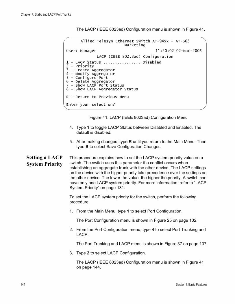
Chapter 7: Static and LACP Port Trunks
The LACP (IEEE 8023ad) Configuration menu is shown in Figure 41.
Figure 41. LACP (IEEE 8023ad) Configuration Menu
4. Type 1 to toggle LACP Status between Disabled and Enabled. The default is disabled.
5. After making changes, type R until you return to the Main Menu. Then type S to select Save Configuration Changes.
Setting a LACPSystem Priority
This procedure explains how to set the LACP system priority value on a switch. The switch uses this parameter if a conflict occurs when establishing an aggregate trunk with the other device. The LACP settings on the device with the higher priority take precedence over the settings on the other device. The lower the value, the higher the priority. A switch can have only one LACP system priority. For more information, refer to “LACP System Priority” on page 131.
To set the LACP system priority for the switch, perform the following procedure:
1. From the Main Menu, type 1 to select Port Configuration.
The Port Configuration menu is shown in Figure 25 on page 102.
2. From the Port Configuration menu, type 4 to select Port Trunking and LACP.
The Port Trunking and LACP menu is shown in Figure 37 on page 137.
3. Type 2 to select LACP Configuration.
The LACP (IEEE 8023ad) Configuration menu is shown in Figure 41 on page 144.
Allied Telesyn Ethernet Switch AT-94xx - AT-S63Marketing
User: Manager 11:20:02 02-Mar-2005
LACP (IEEE 802.3ad) Configuration
1 - LACP Status ................ Disabled2 - Priority3 - Create Aggregator4 - Modify Aggregator5 - Configure Port6 - Delete Aggregator7 - Show LACP Port Status8 - Show LACP Aggregator Status
R - Return to Previous Menu
Enter your selection?
144 Section I: Basic Features
AT-S63 Management Software Menus Interface User’s Guide
4. Type 2 to select Priority.
The following prompt is displayed:
Enter Priority [0x1 - 0xFFFF]: [0x1 to 0xffff] -> 0x
5. Enter the new value is hexadecimal. The range is 1 to FFFF. The lower the value, the higher the priority. The prefix “0x” indicates that the number is hexadecimal.
The new priority value takes effect immediately on the switch.
6. After making changes, type R until you return to the Main Menu. Then type S to select Save Configuration Changes.
Creating anAggregator
To create an aggregator, perform the following procedure:
CautionDo not connect the cables to the ports of the aggregator on the switch until after you have configured the aggregator with the management software and enabled LACP. Connecting the cables before configuring the software and activating the protocol will create a loop in your network topology. Data loops can result in broadcast storms and poor network performance.
NoteBefore creating an aggregator, verify that the ports that will be members of the aggregator are set to Auto-Negotiation or 1000 Mbps, full-duplex. Aggregate trunks do not support half-duplex mode.
1. From the Main Menu, type 1 to select Port Configuration.
The Port Configuration menu is shown in Figure 25 on page 102.
2. From the Port Configuration menu, type 4 to select Port Trunking and LACP.
The Port Trunking and LACP menu is shown in Figure 37 on page 137.
3. Type 2 to select LACP Configuration.
The LACP (IEEE 8023ad) Configuration menu is shown in Figure 41 on page 144.
4. Type 3 to select Create Aggregator.
Section I: Basic Features 145

Chapter 7: Static and LACP Port Trunks
The Create LACP (IEEE 8023ad) Aggregator menu is shown in Figure 42.
Figure 42. Create LACP (IEEE 8023ad) Aggregator Menu
5. Configure the following parameters as necessary:
1 - AggregatorSpecifies a name for the aggregator. The name can be up to 20 alphanumeric characters. Spaces are allowed, but special characters, such as asterisks and exclamation points, are not. Each aggregator must have a unique name.
2 - AdminkeySpecifies a unique adminkey value for the aggregator. The value is entered in hexadecimal. The range is 1 to FFFF. For background information, refer to “Adminkey Parameter” on page 131.
3 - Distribution ModeSets the load distribution method. Possible settings are:
SRC MAC - Source MAC addressDST MAC - Destination MAC addressSRC/DST MAC - Source address /destination MAC address SRC IP - Source IP address trunkingDST IP - Destination IP address trunkingSRC/DST IP - Source address /destination IP address
The default is SRC/DST MAC. For background information, refer to “Load Distribution Methods” on page 134.
4 - Port RangeSpecifies the aggregator ports. An aggregator can contain any number of ports on the switch. You can identify the ports individually (for
Allied Telesyn Ethernet Switch AT-9400 Series - AT-S63Marketing
User: Manager 11:20:02 02-Mar-2005
Create LACP (IEEE 802.3ad) Aggregator
1 - Aggregator ..................2 - Adminkey .................... 0x00003 - Distribution Mode ........... SRC/DST MAC4 - Port Range ..................C - Create Aggregator
R - Return to Previous Menu
Enter your selection?
146 Section I: Basic Features

AT-S63 Management Software Menus Interface User’s Guide
example, 3,7,10), as a range (for example, 5-11), or both (for example, 2,4,11-14).
6. After you configure the parameters, type C to select Create Aggregator.
The aggregator is created on the switch.
7. If LACP is not enabled on the switch, perform the procedure “Enabling or Disabling LACP” on page 143 and activate the protocol.
8. Configure LACP on the other network device.
9. Connect the cables to the ports of the aggregator on both the switch and the other network device.
The aggregator and its aggregate trunk(s) are now ready for network operations.
CautionDo not connect the cables to the ports of the aggregator on the switch until after you have enabled LACP. Connecting the cables before activating the protocol will create a loop in your network topology. Data loops can result in broadcast storms and poor network performance.
10. Repeat this procedure to create additional aggregators, if needed.
11. After making changes, type R until you return to the Main Menu. Then type S to select Save Configuration Changes.
Modifying anAggregator
This procedure explains how to modify an aggregator. You can change an aggregator’s name, adminkey, or load distribution method. You can also use this procedure to add or remove ports. To modify an aggregator, you need to know its name or adminkey key. It is recommended that you review the section “LACP Trunk Guidelines” on page 133 before modifying an aggregator.
CautionIf you will be adding or removing ports from the aggregator, you should disconnect all network cables from the ports of the aggregator on the switch before performing the procedure. Adding or removing ports without first disconnecting the cables can result in loops in your network topology, which can result in broadcast storms and poor network performance.
To modify an aggregator, perform the following procedure:
1. From the Main Menu, type 1 to select Port Configuration.
Section I: Basic Features 147
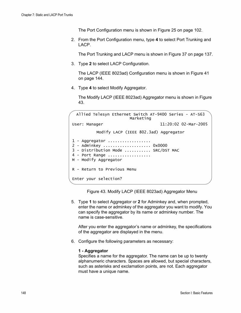
Chapter 7: Static and LACP Port Trunks
The Port Configuration menu is shown in Figure 25 on page 102.
2. From the Port Configuration menu, type 4 to select Port Trunking and LACP.
The Port Trunking and LACP menu is shown in Figure 37 on page 137.
3. Type 2 to select LACP Configuration.
The LACP (IEEE 8023ad) Configuration menu is shown in Figure 41 on page 144.
4. Type 4 to select Modify Aggregator.
The Modify LACP (IEEE 8023ad) Aggregator menu is shown in Figure 43.
Figure 43. Modify LACP (IEEE 8023ad) Aggregator Menu
5. Type 1 to select Aggregator or 2 for Adminkey and, when prompted, enter the name or adminkey of the aggregator you want to modify. You can specify the aggregator by its name or adminkey number. The name is case-sensitive.
After you enter the aggregator’s name or adminkey, the specifications of the aggregator are displayed in the menu.
6. Configure the following parameters as necessary:
1 - AggregatorSpecifies a name for the aggregator. The name can be up to twenty alphanumeric characters. Spaces are allowed, but special characters, such as asterisks and exclamation points, are not. Each aggregator must have a unique name.
Allied Telesyn Ethernet Switch AT-9400 Series - AT-S63Marketing
User: Manager 11:20:02 02-Mar-2005
Modify LACP (IEEE 802.3ad) Aggregator
1 - Aggregator ..................2 - Adminkey .................... 0x00003 - Distribution Mode ........... SRC/DST MAC4 - Port Range ..................M - Modify Aggregator
R - Return to Previous Menu
Enter your selection?
148 Section I: Basic Features
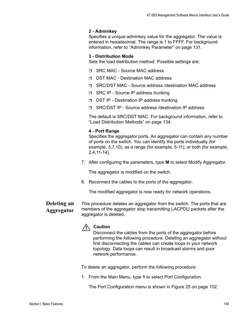
AT-S63 Management Software Menus Interface User’s Guide
2 - AdminkeySpecifies a unique adminkey value for the aggregator. The value is entered in hexadecimal. The range is 1 to FFFF. For background information, refer to “Adminkey Parameter” on page 131.
3 - Distribution ModeSets the load distribution method. Possible settings are:
SRC MAC - Source MAC addressDST MAC - Destination MAC addressSRC/DST MAC - Source address /destination MAC address SRC IP - Source IP address trunkingDST IP - Destination IP address trunkingSRC/DST IP - Source address /destination IP address
The default is SRC/DST MAC. For background information, refer to “Load Distribution Methods” on page 134.
4 - Port RangeSpecifies the aggregator ports. An aggregator can contain any number of ports on the switch. You can identify the ports individually (for example, 3,7,10), as a range (for example, 5-11), or both (for example, 2,4,11-14).
7. After configuring the parameters, type M to select Modify Aggregator.
The aggregator is modified on the switch.
8. Reconnect the cables to the ports of the aggregator.
The modified aggregator is now ready for network operations.
Deleting anAggregator
This procedure deletes an aggregator from the switch. The ports that are members of the aggregator stop transmitting LACPDU packets after the aggregator is deleted.
CautionDisconnect the cables from the ports of the aggregator before performing the following procedure. Deleting an aggregator without first disconnecting the cables can create loops in your network topology. Data loops can result in broadcast storms and poor network performance.
To delete an aggregator, perform the following procedure:
1. From the Main Menu, type 1 to select Port Configuration.
The Port Configuration menu is shown in Figure 25 on page 102.
Section I: Basic Features 149

Chapter 7: Static and LACP Port Trunks
2. From the Port Configuration menu, type 4 to select Port Trunking and LACP.
The Port Trunking and LACP menu is shown in Figure 37 on page 137.
3. Type 2 to select LACP Configuration.
The LACP (IEEE 8023ad) Configuration menu is shown in Figure 41 on page 144.
4. Type 6 to select Delete Aggregator.
The following prompt is displayed:
Enter Aggregator Name [Max up to 20 alphanumeric characters]:
5. Enter the name of the aggregator you want to delete. The name is case-sensitive. You can delete only one aggregator at a time.
Are you sure you want to delete this aggregator (Y/N) [Yes/No] ->
6. Type Y to delete the aggregator or N to cancel the procedure.
If you entered Yes, the aggregator is deleted.
ConfiguringLACP PortParameters
This procedure explains how to configure a port’s priority value. This parameter determines whether a port is active or in standby mode as part of an aggregate trunk. For further information, refer to “LACP Port Priority Parameter” on page 131. This procedure also shows how to assign a port to a different aggregator.
NoteTo remove a port from an aggregator without assigning it to a different one, skip this procedure and instead perform “Modifying an Aggregator” on page 147. When modifying the aggregator, reenter its port list, omitting the port you want to remove.
To configure a port, perform the following procedure:
1. From the Main Menu, type 1 to select Port Configuration.
The Port Configuration menu is shown in Figure 25 on page 102.
2. From the Port Configuration menu, type 4 to select Port Trunking and LACP.
The Port Trunking and LACP menu is shown in Figure 37 on page 137.
3. Type 2 to select LACP Configuration.
150 Section I: Basic Features
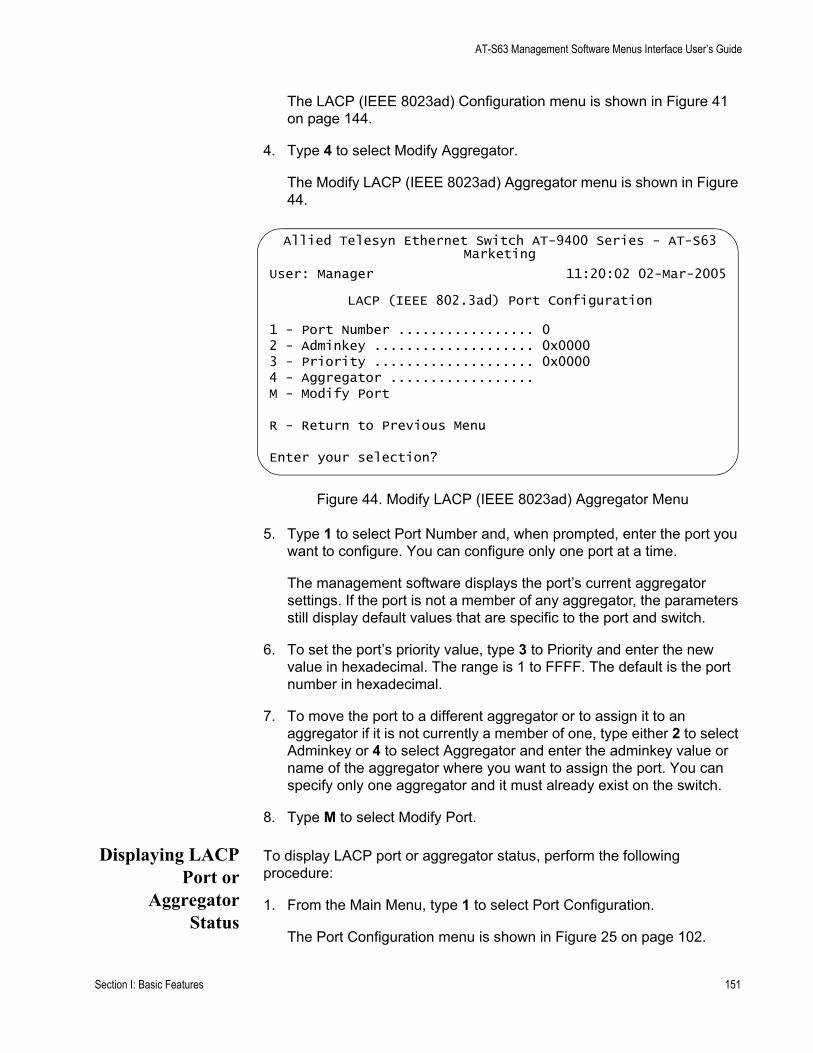
AT-S63 Management Software Menus Interface User’s Guide
The LACP (IEEE 8023ad) Configuration menu is shown in Figure 41 on page 144.
4. Type 4 to select Modify Aggregator.
The Modify LACP (IEEE 8023ad) Aggregator menu is shown in Figure 44.
Figure 44. Modify LACP (IEEE 8023ad) Aggregator Menu
5. Type 1 to select Port Number and, when prompted, enter the port you want to configure. You can configure only one port at a time.
The management software displays the port’s current aggregator settings. If the port is not a member of any aggregator, the parameters still display default values that are specific to the port and switch.
6. To set the port’s priority value, type 3 to Priority and enter the new value in hexadecimal. The range is 1 to FFFF. The default is the port number in hexadecimal.
7. To move the port to a different aggregator or to assign it to an aggregator if it is not currently a member of one, type either 2 to select Adminkey or 4 to select Aggregator and enter the adminkey value or name of the aggregator where you want to assign the port. You can specify only one aggregator and it must already exist on the switch.
8. Type M to select Modify Port.
Displaying LACPPort or
AggregatorStatus
To display LACP port or aggregator status, perform the following procedure:
1. From the Main Menu, type 1 to select Port Configuration.
The Port Configuration menu is shown in Figure 25 on page 102.
Allied Telesyn Ethernet Switch AT-9400 Series - AT-S63Marketing
User: Manager 11:20:02 02-Mar-2005
LACP (IEEE 802.3ad) Port Configuration
1 - Port Number ................. 02 - Adminkey .................... 0x00003 - Priority .................... 0x00004 - Aggregator ..................M - Modify Port
R - Return to Previous Menu
Enter your selection?
Section I: Basic Features 151
Chapter 7: Static and LACP Port Trunks
2. From the Port Configuration menu, type 4 to select Port Trunking and LACP.
The Port Trunking and LACP menu is shown in Figure 37 on page 137.
3. Type 2 to select LACP Configuration.
The LACP (IEEE 8023ad) Configuration menu is shown in Figure 41 on page 144.
4. To view port status, type 7 to select Show LACP Port Status. To view aggregator status, type 8 to select Show LACP Aggregator Status.
Figure 45 is an example of the LACP (IEEE 802.3ad) Port Status menu. The information in this window is for viewing purposes only. For definitions, refer to the IEEE 802.3ad standard.
Figure 45. LACP (IEEE 802.3ad Port Status Menu
Figure 46 is an example of the LACP (IEEE 802.3ad) Aggregator Status menu. The information is for viewing purposes only. An
Allied Telesyn Ethernet Switch AT-9400 Series - AT-S63Marketing
User: Manager 11:20:02 02-Mar-2005
LACP (IEEE 802.3ad) Port Status
Port ............. 01Aggregator ....... Sales server
ACTOR PARTNER====================================++++++++===========================Actor Port ............. 06 Partner Port ......... 00Selected ............... SELECTED Partner System ....... 00-30-84-00-00-02Oper Key ............... 0x0050 Oper Key ............ 0x0004Oper Port Priority .... 0x0006 Oper Port Priority ... 0x0007Individual ............. NO Individual ........... NOSynchronized............ YES Synchronized.......... YESCollecting ............ YES Collecting ........... YESDistributing ........... YES Distributing ......... NODefaulted .............. NO Defaulted ............ NOExpired ................ NO Expired .............. NOActor Churn .......... YES Partner Churn ........ YES
N - Next PageU - Update DisplayR - Return to Previous Menu
Enter your selection?
152 Section I: Basic Features
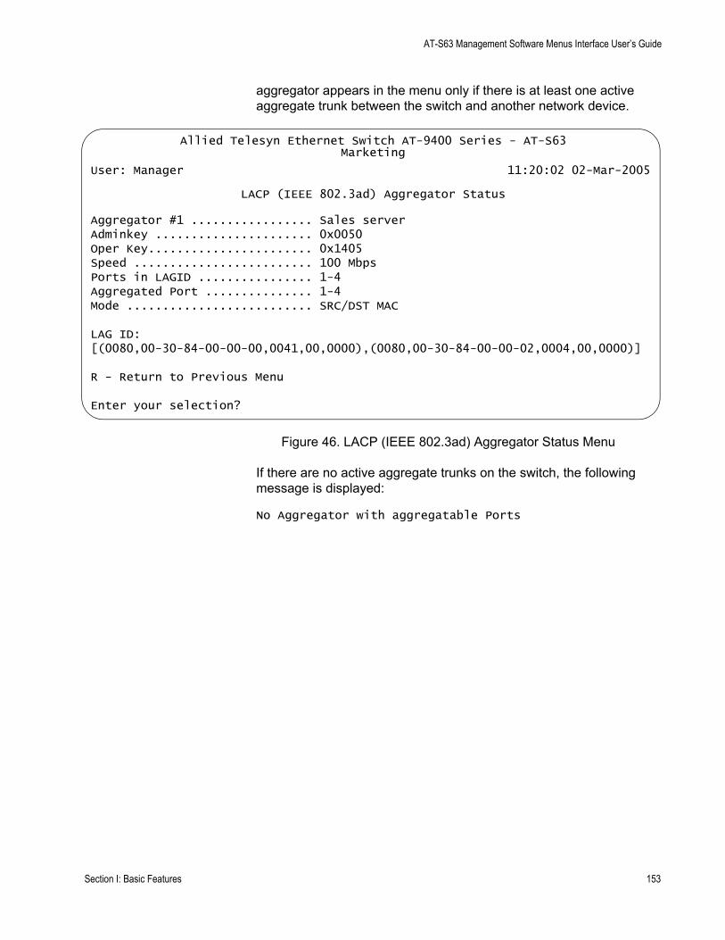
AT-S63 Management Software Menus Interface User’s Guide
aggregator appears in the menu only if there is at least one active aggregate trunk between the switch and another network device.
Figure 46. LACP (IEEE 802.3ad) Aggregator Status Menu
If there are no active aggregate trunks on the switch, the following message is displayed:
No Aggregator with aggregatable Ports
Allied Telesyn Ethernet Switch AT-9400 Series - AT-S63Marketing
User: Manager 11:20:02 02-Mar-2005
LACP (IEEE 802.3ad) Aggregator Status
Aggregator #1 ................. Sales serverAdminkey ...................... 0x0050Oper Key....................... 0x1405Speed ......................... 100 MbpsPorts in LAGID ................ 1-4Aggregated Port ............... 1-4Mode .......................... SRC/DST MAC
LAG ID:[(0080,00-30-84-00-00-00,0041,00,0000),(0080,00-30-84-00-00-02,0004,00,0000)]
R - Return to Previous Menu
Enter your selection?
Section I: Basic Features 153

Chapter 7: Static and LACP Port Trunks
154 Section I: Basic Features
Chapter 8
Port Mirroring
This chapter contains the procedures for creating and deleting a port mirror. Sections in the chapter include:
“Port Mirroring Overview” on page 156“Creating a Port Mirror” on page 157“Disabling a Port Mirror” on page 159“Modifying a Port Mirror” on page 160“Displaying the Port Mirror” on page 161
Section I: Basic Operations 155
Chapter 8: Port Mirroring
Port Mirroring Overview
The port mirroring feature allows you to unobtrusively monitor the traffic being received and transmitted on one or more ports on a switch by having the traffic copied to another switch port. You can connect a network analyzer to the port where the traffic is being copied and monitor the traffic on the other ports without impacting network performance or speed.
The port(s) whose traffic you want to mirror is called the source port(s). The port where the traffic will be copied to is called the destination port.
Observe the following guidelines when you create a port mirror:
You can select more than one source port at a time. However, the more ports you mirror, the less likely the destination port will be able to handle all the traffic. For example, if you mirror the traffic of six heavily active ports, the destination port is likely to drop packets, meaning that it will not provide an accurate mirror of the traffic of the six source ports.The source and destination ports must be located on the same switch.You can mirror either the ingress or egress traffic of the source ports, or both.
NoteWhen a transceiver is inserted into an uplink slot and a link is established, that slot becomes a primary uplink port and the corresponding backup port, 23R or 24R, automatically transitions to redundant uplink status. Any settings for port mirroring remain intact when the backup port makes the transition to a redundant uplink state.
156 Section I: Basic Operations

AT-S63 Management Software Menus Interface User’s Guide
Creating a Port Mirror
To create a port mirror, perform the following procedure:
1. From the Main Menu, type 1 to select Port Configuration.
The Port Configuration menu is shown in Figure 25 on page 102.
2. From the Port Configuration menu, type 6 to select Port Mirroring.
The Port Mirroring menu is shown in Figure 47.
Figure 47. Port Mirroring Menu #1
3. From the Port Mirroring menu, type 1 to select Enable/Disable.
The following prompt is displayed.
Enter Enable(E)/Disable(D):
4. Type E to enable the feature.
New options are added to the Port Mirroring menu, as shown in Figure 48.
Figure 48. Port Mirroring Menu #2
Allied Telesyn Ethernet Switch AT-94xx - AT-S63Marketing
User: Manager 11:20:02 02-Mar-2005
Port Mirroring
1 - Enable/Disable .................... Disabled
R - Return to Previous Menu
Enter your selection?
Allied Telesyn Ethernet Switch AT-94xx - AT-S63Marketing
User: Manager 11:20:02 02-Mar-2005
Port Mirroring
1 - Enable/Disable ...................... Enabled2 - Mirror-To (Destination) Port ........ None3 - Ingress (Rx) Mirror (Source) Ports .. None4 - Egress (Tx) Mirror (Source) Ports ... None
R - Return to Previous Menu
Enter your selection?
Section I: Basic Operations 157

Chapter 8: Port Mirroring
5. Type 2 to select Mirror-To (Destination) Port.
The following prompt is displayed:
Mirror-To Port (0-24):
6. Enter the number of the port that functions as the destination port. This is the port where the traffic from the source ports will be copied to and where the network analyzer will be located. You can specify only one destination port.
7. If you want to mirror the ingress (received) traffic on one or more ports, type 3 to select Ingress(Rx) Mirror (Source Ports.
The following prompt is displayed:
Ingress Mirror Ports (1-24) (or None):
8. Enter the ports. You can identify the ports individually (for example, 3,7,10), as a range (for example, 5-11), or both (for example, 2,4,11-14). Entering “0” (zero) removes all ingress source ports.
9. If you want to mirror the egress (transmitted) traffic from one or more ports, type 4 to select Egress Mirror Port.
The following prompt is displayed:
Egress Mirror Ports (1-24) (or None):
10. Enter the ports. Entering “0” (zero) removes all egress source ports.
NoteIf you want to monitor both the ingress and egress traffic of the source ports, you must specify the ports in both selection 3 and 4.
The port mirror is now functional. Attach a network analyzer to the destination port to monitor the traffic on the source ports.
11. After making changes, type R until you return to the Main Menu. Then type S to select Save Configuration Changes.
158 Section I: Basic Operations
AT-S63 Management Software Menus Interface User’s Guide
Disabling a Port Mirror
To delete a port mirror, perform the following procedure:
1. From the Main Menu, type 1 to select Port Configuration.
The Port Configuration menu is shown in Figure 25 on page 102.
2. From the Port Configuration menu, type 6 to select Port Mirroring.
The Port Mirroring menu is shown in Figure 48 on page 157.
3. From the Port Mirroring Menu, type 1 to select Enable/Disable.
The following prompt is displayed.
Enter Enable(E)/Disable(D):
4. Type D to disable the feature.
Port mirroring on the switch is now disabled. You can disconnect the network analyzer from the destination port and use the port for normal network operations.
Section I: Basic Operations 159
Chapter 8: Port Mirroring
Modifying a Port Mirror
To modify the port mirror, perform the following procedure:
1. From the Main Menu, type 1 to select Port Configuration.
The Port Configuration menu is shown in Figure 25 on page 102.
2. From the Port Configuration menu, type 6 to select Port Mirroring.
The Port Mirroring menu is shown in Figure 48 on page 157.
3. Type 2 to select Mirror-To (Destination) Port.
The following prompt is displayed:
Mirror-To Port (0-24):
4. Enter the number of the port that will function as the destination port. This is the port where the traffic from the source ports will be copied to and where the network analyzer will be located. You can specify only one destination port.
5. If you want to mirror the ingress (received) traffic on one or more ports, type 3 to select Ingress(Rx) Mirror (Source Ports.
The following prompt is displayed:
Ingress Mirror Ports (01-24) (0=None):
6. Enter the ports. You can identify the ports individually (for example, 3,7,10), as a range (for example, 5-11), or both (for example, 2,4,11-14). Entering “0” (zero) removes all ingress source ports.
7. If you want to mirror the egress (transmitted) traffic from one or more ports, type 4 to select Egress Mirror Port.
The following prompt is displayed:
Egress Mirror Ports (01-24) (0=None):
8. Enter the ports. Entering “0” (zero) removes all egress source ports.
9. After making changes, type R until you return to the Main Menu. Then type S to select Save Configuration Changes.
160 Section I: Basic Operations
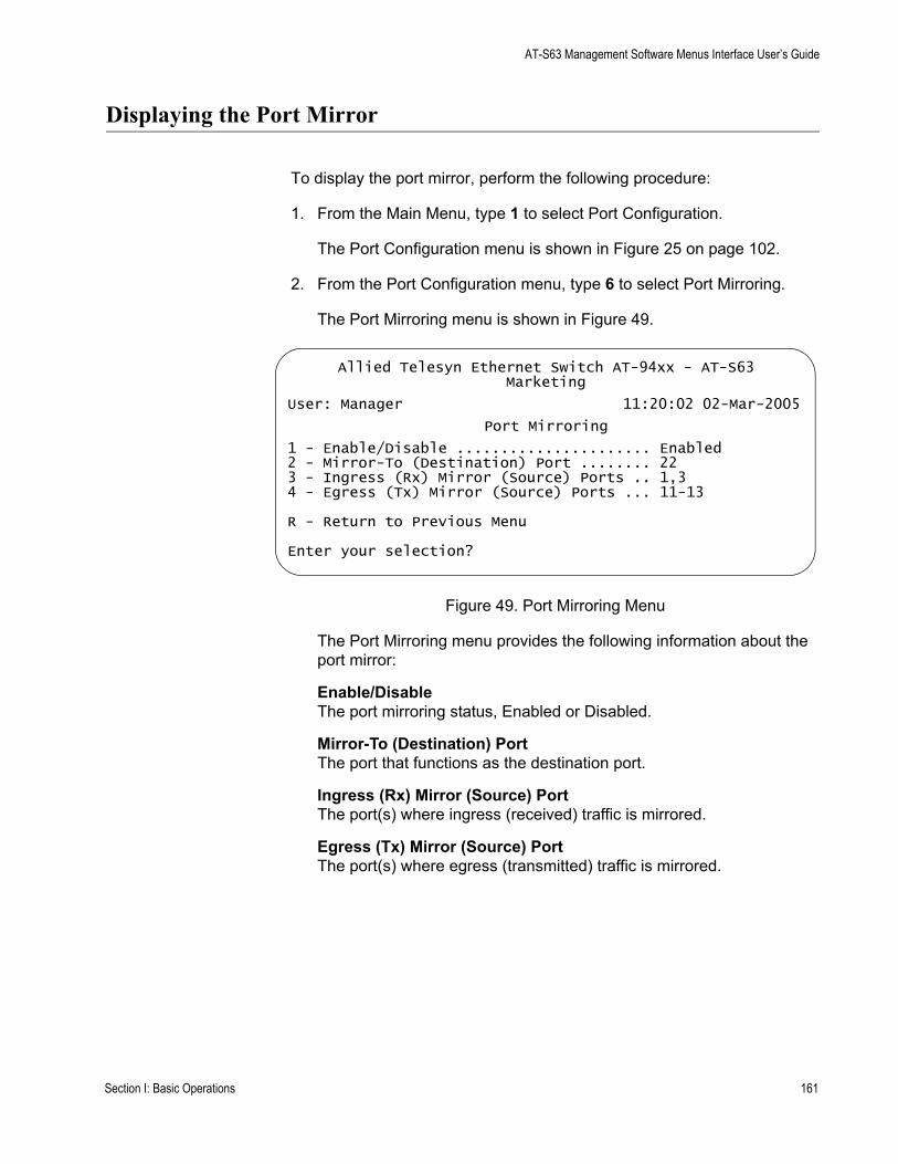
AT-S63 Management Software Menus Interface User’s Guide
Displaying the Port Mirror
To display the port mirror, perform the following procedure:
1. From the Main Menu, type 1 to select Port Configuration.
The Port Configuration menu is shown in Figure 25 on page 102.
2. From the Port Configuration menu, type 6 to select Port Mirroring.
The Port Mirroring menu is shown in Figure 49.
Figure 49. Port Mirroring Menu
The Port Mirroring menu provides the following information about the port mirror:
Enable/DisableThe port mirroring status, Enabled or Disabled.
Mirror-To (Destination) PortThe port that functions as the destination port.
Ingress (Rx) Mirror (Source) PortThe port(s) where ingress (received) traffic is mirrored.
Egress (Tx) Mirror (Source) PortThe port(s) where egress (transmitted) traffic is mirrored.
Allied Telesyn Ethernet Switch AT-94xx - AT-S63Marketing
User: Manager 11:20:02 02-Mar-2005
Port Mirroring
1 - Enable/Disable ...................... Enabled2 - Mirror-To (Destination) Port ........ 223 - Ingress (Rx) Mirror (Source) Ports .. 1,34 - Egress (Tx) Mirror (Source) Ports ... 11-13
R - Return to Previous Menu
Enter your selection?
Section I: Basic Operations 161

Chapter 8: Port Mirroring
162 Section I: Basic Operations

Chapter 9
Networking Stack
The AT-S63 management software allows you to perform a few basic functions on the switch’s TCP/IP stack. The functions include viewing the switch’s Address Resolution Protocol (ARP) table and routing table. The switch uses these tables when you instruct it to perform a management function that requires interaction with another network device. You can also view the TCP connections table, which lists the active Telnet and web browser management sessions, and a global TCP table, which displays basic TCP status and statistics.
This chapter contains the following sections:
“Managing the Address Resolution Protocol (ARP) Table” on page 164“Displaying the Route Table” on page 169“Displaying the TCP Connections” on page 171“Deleting a TCP Connection” on page 174“Displaying the TCP Global Information” on page 175
Section I: Basic Operations 163
Chapter 9: Networking Stack
Managing the Address Resolution Protocol (ARP) Table
The switch has an Address Resolution Protocol (ARP) table for storing IP addresses of network devices and their corresponding MAC addresses. The switch uses the table whenever you issue a management command that requires the switch’s AT-S63 management software to interact with another device on the network. An example would be if you instructed the switch to ping another network device or download a new AT-S63 image file or configuration file from a network server.
The value of the ARP table is that it eliminates the need of the switch to issue unnecessary ARP broadcast packets when performing some management functions. This can improve the switch’s response time as well as reduce the number of broadcast packets on your network.
The table can hold up to 11 entries. There are two types of entries. One type is permanent. There is only one permanent entry. It is used by the switch for internal diagnostics and it can never be removed from the table.
The other type is a temporary entry, of which there can be up to ten. The switch adds a temporary entry whenever its management software interacts with another network device during a management function. When you enter a management command that contains an IP address not in the table, the switch sends out an ARP broadcast packet. When the remote device responds with its MAC address, the switch adds the device’s IP address and MAC address as a new temporary entry to the table.
A temporary entry remains in the table only while active. An entry remains active so long as it is periodically used by the switch for management functions. If an entry is inactive for a specified period of time, referred to as ARP cache timeout, it is automatically removed from the table. This value is adjustable, as explained in “Setting the ARP Cache Timeout” on page 168. The default is 400 seconds. If the table becomes full, the management software continues to add new entries by deleting the oldest entries.
The management software allows you to view the contents of the table. You can also delete individual table entries or delete all the entries. These functions are explained in the following subsections:
“Displaying the ARP Table” on page 165“Deleting an ARP Table Entry” on page 166“Resetting the ARP Table” on page 167“Setting the ARP Cache Timeout” on page 168
164 Section I: Basic Operations

AT-S63 Management Software Menus Interface User’s Guide
NoteThe switch does not use the ARP table to move packets through its switching matrix. The switch refers to the table only when performing a management function that involves interaction with another network node.
Displaying theARP Table
To display the ARP table, perform the following procedure:
1. From the Main Menu, type 5 to select System Administration.
The System Administration menu is shown in Figure 4 on page 46.
2. From the System Administration menu, type 9 to select System Utilities.
The System Utilities menu is shown in Figure 7 on page 53.
3. From the System Utilities menu, type 6 to select Networking Stack.
The Networking Stack menu is shown in Figure 50.
Figure 50. Networking Stack Menu
4. From the Networking Stack menu, type 1 to select Display ARP Table.
Allied Telesyn Ethernet Switch AT-94xx - AT-S63Marketing
User: Manager 11:20:02 02-Mar-2005
Networking Stack
1 - Display ARP Table2 - Delete ARP Entry3 - Reset ARP Table4 - Display Route Table5 - Display TCP Connections6 - Display TCP Global Information7 - Delete TCP Connection
R - Return to Previous Menu
Enter your selection?
Section I: Basic Operations 165
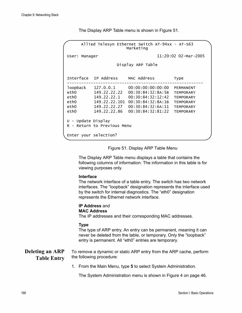
Chapter 9: Networking Stack
The Display ARP Table menu is shown in Figure 51.
Figure 51. Display ARP Table Menu
The Display ARP Table menu displays a table that contains the following columns of information: The information in this table is for viewing purposes only.
InterfaceThe network interface of a table entry. The switch has two network interfaces. The “loopback” designation represents the interface used by the switch for internal diagnostics. The “eth0” designation represents the Ethernet network interface.
IP Address and MAC AddressThe IP addresses and their corresponding MAC addresses.
TypeThe type of ARP entry. An entry can be permanent, meaning it can never be deleted from the table, or temporary. Only the “loopback” entry is permanent. All “eth0” entries are temporary.
Deleting an ARPTable Entry
To remove a dynamic or static ARP entry from the ARP cache, perform the following procedure:
1. From the Main Menu, type 5 to select System Administration.
The System Administration menu is shown in Figure 4 on page 46.
Allied Telesyn Ethernet Switch AT-94xx - AT-S63Marketing
User: Manager 11:20:02 02-Mar-2005
Display ARP Table
Interface IP Address MAC Address Type---------------------------------------------------------loopback 127.0.0.1 00:00:00:00:00:00 PERMANENTeth0 149.22.22.22 00:30:84:32:8A:5B TEMPORARYeth0 149.22.22.1 00:30:84:32:12:42 TEMPORARYeth0 149.22.22.101 00:30:84:32:8A:1B TEMPORARYeth0 149.22.22.27 00:30:84:32:6A:11 TEMPORARYeth0 149.22.22.86 00:30:84:32:81:22 TEMPORARY
U - Update DisplayR - Return to Previous Menu
Enter your selection?
166 Section I: Basic Operations

AT-S63 Management Software Menus Interface User’s Guide
2. From the System Administration menu, type 9 to select System Utilities.
The System Utilities menu is shown in Figure 7 on page 53.
3. From the System Utilities menu, type 6 to select Networking Stack.
The Networking Stack menu is shown in Figure 50 on page 165.
4. From the Networking Stack menu, type 2 to select Delete ARP Entry.
The following prompt is displayed:
Enter IP address of ARP entry to delete:
5. Enter the IP address of the entry you want to delete. You cannot delete the first entry in the table with the interface designation “loopback.”
The entry is immediately removed from the switch.
6. Repeat steps 4 and 5 to delete additional ARP table entries.
You do not need to return to the main menu to save the changes made with this procedure.
7. Return to the Main Menu.
Resetting theARP Table
To clear all entries from the ARP table, perform the following procedure:
1. From the Main Menu, type 5 to select System Administration.
The System Administration menu is shown in Figure 4 on page 46.
2. From the System Administration menu, type 9 to select System Utilities.
The System Utilities menu is shown in Figure 7 on page 53.
3. From the System Utilities menu, type 6 to select Networking Stack.
The Networking Stack menu is shown in Figure 50 on page 165.
4. From the Networking Stack menu, type 3 to select Reset ARP Table.
NoteNo confirmation prompt is displayed. All entries in the ARP table are immediately deleted, with the exception of the “loopback” entry, which cannot be deleted.
The switch begins to add new entries to the table as it performs new management functions in conjunction with other network devices.
Section I: Basic Operations 167
Chapter 9: Networking Stack
5. Return to the Main Menu.
Setting the ARPCache Timeout
Inactive temporary entries in the ARP table are timed out according to the ARP cache timeout value. This parameter prevents the table from becoming full with inactive entries. The default setting is 400 seconds. To set this value, perform the following procedure:
1. From the Main Menu, type 5 to select System Administration.
The System Administration menu is shown in Figure 4 on page 46.
2. From the System Administration menu, type 2 to select System Configuration.
The System Configuration menu is shown in Figure 5 on page 47.
3. Type A to select ARP Cache Timeout.
The following prompt is displayed:
Enter your new value -> [1 to 260000] 400
4. Type a value between 1 and 260000 seconds and press Enter.
5. Return to the Main Menu.
168 Section I: Basic Operations

AT-S63 Management Software Menus Interface User’s Guide
Displaying the Route Table
The routing table is used by the switch when a remote node specified in a management command is not on the same physical network as the switch. The table contains the IP address of the next hop to reaching the remote network or device. For example, the switch might refer to the table if you instructed it to download a new AT-S63 image file from a network server that was on a different physical network.
To display the route table, perform the following procedure:
1. From the Main Menu, type 5 to select System Administration.
The System Administration menu is shown in Figure 4 on page 46.
2. From the System Administration menu, type 9 to select System Utilities.
The System Utilities menu is shown in Figure 7 on page 53.
3. From the System Utilities menu, type 6 to select Networking Stack.
The Networking Stack menu is shown in Figure 50 on page 165.
4. From the Networking Stack menu, type 4 to select Display Route Table.
The Display Route Table menu is shown in Figure 52.
Figure 52. Display Route Table Menu
Allied Telesyn Ethernet Switch AT-94xx - AT-S63Marketing
User: Manager 11:20:02 02-Mar-2005
Display Route Table
Destination Mask Next Hop Interface---------------------------------------------------------------127.0.0.0 255.0.0.0 127.0.0.1 loopback169.254.0.0 255.255.0.0 169.254.37.1 eth0169.254.37.1 255.255.255.255 127.0.0.1 loopback
U - Update DisplayR - Return to Previous Menu
Enter your selection?
Section I: Basic Operations 169
Chapter 9: Networking Stack
The information in this menu is for viewing purposes only. The Display Route Table menu contains the following columns of information.
DestinationThe IP address of a destination network, subnetwork, or end node.
MaskA filter used to designate the active part of the destination IP address. A binary 1 in the mask indicates an active bit in the address while a binary 0 indicates that the corresponding bit in the address is not.
Next HopThe IP address of the next intermediary device to reaching the destination network, subnetwork, or end node.
InterfaceThe interface on the switch where the next hop is located. The switch has two interfaces. The interface “loopback” is for internal diagnostics only. The other interface is “eth0.”
5. Return to the Main Menu.
170 Section I: Basic Operations
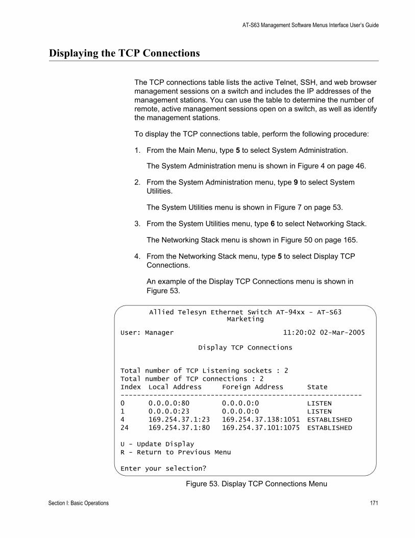
AT-S63 Management Software Menus Interface User’s Guide
Displaying the TCP Connections
The TCP connections table lists the active Telnet, SSH, and web browser management sessions on a switch and includes the IP addresses of the management stations. You can use the table to determine the number of remote, active management sessions open on a switch, as well as identify the management stations.
To display the TCP connections table, perform the following procedure:
1. From the Main Menu, type 5 to select System Administration.
The System Administration menu is shown in Figure 4 on page 46.
2. From the System Administration menu, type 9 to select System Utilities.
The System Utilities menu is shown in Figure 7 on page 53.
3. From the System Utilities menu, type 6 to select Networking Stack.
The Networking Stack menu is shown in Figure 50 on page 165.
4. From the Networking Stack menu, type 5 to select Display TCP Connections.
An example of the Display TCP Connections menu is shown in Figure 53.
Figure 53. Display TCP Connections Menu
Allied Telesyn Ethernet Switch AT-94xx - AT-S63Marketing
User: Manager 11:20:02 02-Mar-2005
Display TCP Connections
Total number of TCP Listening sockets : 2Total number of TCP connections : 2Index Local Address Foreign Address State-----------------------------------------------------------0 0.0.0.0:80 0.0.0.0:0 LISTEN1 0.0.0.0:23 0.0.0.0:0 LISTEN4 169.254.37.1:23 169.254.37.138:1051 ESTABLISHED24 169.254.37.1:80 169.254.37.101:1075 ESTABLISHED
U - Update DisplayR - Return to Previous Menu
Enter your selection?
Section I: Basic Operations 171

Chapter 9: Networking Stack
This menu is for viewing purposes only. The Display TCP Connections menu contains the following information:
Total Number of TCP Listening socketsThe number of active listening sockets. There can be a maximum of three listening sockets. One is for the Telnet server, another for SSH, and the last for the web browser server. If a server is disabled, its listening socket does not appear in the table.
Total Number of TCP connectionsThe number of active Telnet, SSH, and web browser connections to the switch.
IndexThe internal socket ID number assigned to the connection.
Local AddressThe IP address of the switch, followed by the TCP port number used by the switch for the connection. The two values are divided by a colon, as illustrated in Figure 54. The port number indicates the type of TCP connection. A port number of 23 indicates a Telnet connection, 22 an SSH connection, and 80 or 443 a web browser HTTP or HTTPS connection, respectively.
Figure 54. IP Address and TCP Port Number
Foreign AddressThe IP address of the management workstation that initiated the connection, followed by the station’s TCP port number.
StateThe state of the TCP connection. The TCP states are:
LISTEN - Waiting for a connection request from any remote TCP and port.SYN-SENT - Waiting for a matching connection request after having sent a connection request.SYN-RECEIVED - Waiting for a confirming connection request acknowledgment after having both received and sent a connection request.ESTABLISHED - An open connection between the switch and the management workstation. This is the normal state for the data transfer portion of the connection.FIN-WAIT-1 - Waiting for a connection termination request from
169.254.37.1:23
IP AddressTCP PortNumber
172 Section I: Basic Operations

AT-S63 Management Software Menus Interface User’s Guide
the remote TCP, or an acknowledgment of the connection termination request previously sent.FIN-WAIT-2 - Waiting for a connection termination request from the remote TCP.CLOSE-WAIT - Waiting for a connection termination request from the local user.CLOSING - Waiting for a connection termination request acknowledgment from the remote TCP.LAST-ACK - Waiting for an acknowledgment of the connection termination request previously sent to the remote TCP which includes an acknowledgment of its connection termination request.TIME-WAIT - Waiting for enough time to pass to be sure the remote TCP received an acknowledgment of its connection termination request.CLOSED - No connection.
The entries for the listening sockets for the Telnet, SSH, and web browser servers are identified in the table with a TCP state of LISTEN. If you disable a server on the switch, its corresponding LISTEN entry is removed from the table. Disabling all the servers leaves the table empty. (The SSH server is disabled by default on the switch.)
The example in Figure 54 on page 172 shows that the Telnet and web browser servers are active on the switch. The table also includes two active TCP connections. Entry 4 is for a Telnet connection and entry 24 is for a web browser HTTP connection.
A web browser management session can have more than one TCP connection open at a time. The different connections are used to carry different packets of the management session.
You cannot change any of the information in this table. The only operating parameter on the switch that affects management TCP connections that you can adjust, other than enabling or disabling the servers, is the TCP port used by the web browser server. The default values are port 80 for HTTP and 443 for HTTPS. For instructions on how to change this setting, refer to “Configuring the Web Server” on page 687. The management software does not allow you to change the default port number of 23 for Telnet connections or 22 for SSH connections.
5. Return to the Main Menu.
Section I: Basic Operations 173
Chapter 9: Networking Stack
Deleting a TCP Connection
This procedure explains how you can use the TCP connections table to end a Telnet, SSH, or web browser management session on a switch. This procedure is useful if a manager forgot to log out after ending a session or if you suspect that an unauthorized person is accessing the switch’s management software.
Before performing this procedure, display the TCP table by performing the procedure “Displaying the TCP Connections” on page 171 and write down on paper the index number of the connection you want to end. A web browser management session can consist of more than one TCP connection.
You cannot delete the entries for the listening sockets for the Telnet, SSH, and web browser servers. To remove a listening socket entry from the table, disable the corresponding server.
To delete a TCP connection, perform the following procedure:
1. From the Main Menu, type 5 to select System Administration.
The System Administration menu is shown in Figure 4 on page 46.
2. From the System Administration menu, type 9 to select System Utilities.
The System Utilities menu is shown in Figure 7 on page 53.
3. From the System Utilities menu, type 6 to select Networking Stack.
The Networking Stack menu is shown in Figure 50 on page 165.
4. From the Networking Stack menu, type 7 to select Delete TCP Connection.
The following prompt is displayed:
Enter the TCP Connection Index: [0 to 65535] ->
5. Enter the connection index number.
To display the TCP connections and see the index numbers, refer to “Displaying the TCP Connections” on page 171.
6. Enter the index number of the connection you want to delete and press Enter. You can enter only one index number at a time.
The connection is deleted and the table is refreshed.
7. Return to the Main Menu.
174 Section I: Basic Operations

AT-S63 Management Software Menus Interface User’s Guide
Displaying the TCP Global Information
The TCP Global Information table displays TCP status and statistics. To view the table, perform the following procedure:
1. From the Main Menu, type 5 to select System Administration.
The System Administration menu is shown in Figure 4 on page 46.
2. From the System Administration menu, type 9 to select System Utilities.
The System Utilities menu is shown in Figure 7 on page 53.
3. From the System Utilities menu, type 6 to select Networking Stack.
The Networking Stack menu is shown in Figure 50 on page 165.
4. From the Networking Stack menu, type 6 to select Display TCP Global Information.
The Display TCP Global Information menu is shown in Figure 55.
Figure 55. Display TCP Global Connections Menu
The Display TCP Global Connections menu contains the following items of information:
RTO min (ms) and RTO max (min)Retransmit time algorithm parameters.
Allied Telesyn Ethernet Switch AT-94xx - AT-S63Marketing
User: Manager 11:20:02 02-Mar-2005
Display TCP Global Information
TCP MIB parameters, counters-------------------------------------RTO min (ms): 1000 RTO max (ms): 240000Max connections: -1Active Opens: 0 Passive Opens: 0Attempt Fails: 0 Established Resets:0Current Established: 0In Segs: 0 In Segs Error: 0Out Segs: 0 Out Segs Retran: 0Out Segs with RST: 0
U - Update DisplayR - Return to Previous Menu
Enter your selection?
Section I: Basic Operations 175
Chapter 9: Networking Stack
Max connectionsThe maximum number of TCP connections allowed.
Active OpensThe number of active TCP opens. Active opens initiate connections.
Passive OpensThe number of TCP passive opens. Passive opens are issued to wait for a connection from another host.
Attempt FailsThe number of failed connection attempts.
Established ResetsThe number of connections established but have not been reset.
Current EstablishedThe number of current connections.
In SegsThe number of segments received.
In Segs ErrorThe number of segments received with an error.
Out SegsThe number of segments transmitted.
Out Segs RetranThe number of segments retransmitted.
Out Segs with RSTThe number of segments transmitted with the RST bit set.
5. Return to the Main Menu.
176 Section I: Basic Operations
Section II
Advanced Operations
The chapters in this section provide information and procedures for advanced switch setup using the AT-S63 management software. The chapters include:
Chapter 10, ”File System” on page 179Chapter 11, ”File Downloads and Uploads” on page 205Chapter 12, ”Event Log” on page 227Chapter 13, ”Classifiers” on page 251Chapter 14, ”Access Control Lists” on page 269Chapter 16, ”Quality of Service” on page 297Chapter 17, “Class of Service” on page 337Chapter 18, ”IGMP Snooping” on page 351Chapter 15, ”Denial of Service Defense” on page 287Chapter 19, ”RRP Snooping” on page 363
Section II: Advanced Operations 177

178 Section II: Advanced Operations
Chapter 10
File System
The chapter describes the AT-S63 file system, and how you can use the file system to copy, rename, and delete system files in flash memory or on a compact flash card. This chapter also explains how you can use the file system to select which boot configuration file you want the switch to use the next time the device is reset or power cycled.
This chapter contains the following sections:
“File System Overview” on page 180“Working with Boot Configuration Files” on page 183“Copying a System File” on page 190“Renaming a System File” on page 192“Deleting a System File” on page 194“Displaying System Files” on page 195“Working with Flash Memory” on page 199“Working with the Compact Flash Card” on page 201
Section II: Advanced Operations 179
Chapter 10: File System
File System Overview
The AT-S63 management software has a file system for storing system files in flash memory on the switch or on a compact flash card. You can view a list of files as well as copy, rename, and delete files. The following file types are supported by the AT-S63 file system:
Configuration filesPublic keysPublic certificatesCertificate enrollment requests
For an explanation of a boot configuration file, refer to “Working with Boot Configuration Files” on page 183.
Public encryption keys, public certificates, and certificate enrollment request files are related to the Secure Sockets Layer (SSL) certificates feature described in Chapter 31, “Encryption Keys” on page 693 and Chapter 32, “PKI Certificates and SSL” on page 719. Refer to those chapters for background information on those files.
NoteThe certificate file, certificate enrollment request file, and key file are supported only on the version of AT-S63 management software that features SSL and PKI security.
This chapter does not explain how to transfer a file from the AT-S63 file system to a management station or to an TFTP server. For those instructions, refer to Chapter 11, “File Downloads and Uploads” on page 205.
NoteThe file system may contain one or more ENC.UKF files. These are encryption key pairs. These files cannot be deleted, copied, or exported from the file system. For instructions on deleting a key, refer to “Deleting an Encryption Key” on page 709.
Some AT-9400 Series switch models also contain a compact flash card slot.The AT-S63 management software supports file system operations on compact flash cards used in these systems including copying files from flash memory to the compact flash card and vice versa.
File NamingConventions
The flash memory file system is a flat file system—directories are not supported. However, directories are supported on compact flash cards. In both types of storage, files are uniquely identified by a file name in the
180 Section II: Advanced Operations
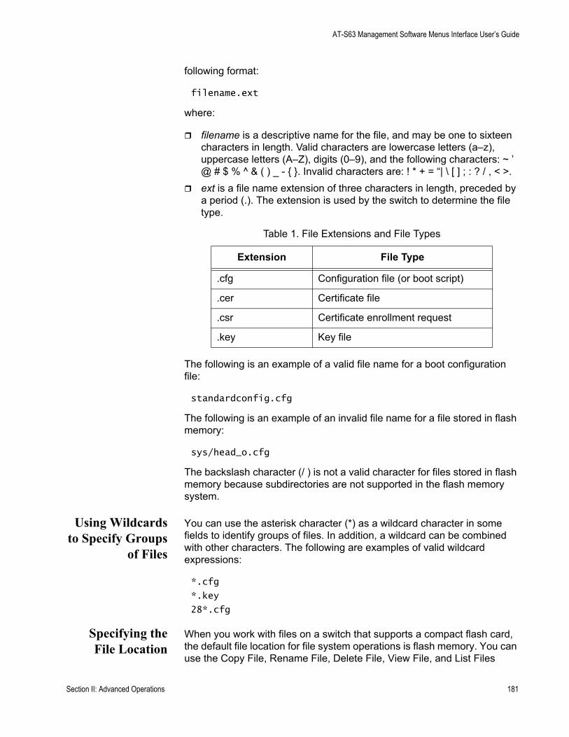
AT-S63 Management Software Menus Interface User’s Guide
following format:
filename.ext
where:
filename is a descriptive name for the file, and may be one to sixteen characters in length. Valid characters are lowercase letters (a–z), uppercase letters (A–Z), digits (0–9), and the following characters: ~ ’ @ # $ % ^ & ( ) _ - { }. Invalid characters are: ! * + = “| \ [ ] ; : ? / , < >.ext is a file name extension of three characters in length, preceded by a period (.). The extension is used by the switch to determine the file type.
The following is an example of a valid file name for a boot configuration file:
standardconfig.cfg
The following is an example of an invalid file name for a file stored in flash memory:
sys/head_o.cfg
The backslash character (/ ) is not a valid character for files stored in flash memory because subdirectories are not supported in the flash memory system.
Using Wildcardsto Specify Groups
of Files
You can use the asterisk character (*) as a wildcard character in some fields to identify groups of files. In addition, a wildcard can be combined with other characters. The following are examples of valid wildcard expressions:
*.cfg
*.key
28*.cfg
Specifying theFile Location
When you work with files on a switch that supports a compact flash card, the default file location for file system operations is flash memory. You can use the Copy File, Rename File, Delete File, View File, and List Files
Table 1. File Extensions and File Types
Extension File Type
.cfg Configuration file (or boot script)
.cer Certificate file
.csr Certificate enrollment request
.key Key file
Section II: Advanced Operations 181

Chapter 10: File System
selections on the File Operations menu (see Figure 56 on page 184) to work with files in flash memory or on a compact flash card by specifying the file location. To specify the file location as flash memory, precede the file name with “flash:.,” For example:
flash:boot.cfg
To specify a file located on a compact flash card, precede the name with “cflash:,” for example:
cflash:switch12.cfg
If you do not specify a location, the default is flash memory.
182 Section II: Advanced Operations

AT-S63 Management Software Menus Interface User’s Guide
Working with Boot Configuration Files
A boot configuration file contains a series of commands that configure the switch’s parameter settings when you power cycle or reset the device. The commands in the file recreate all the VLANs, port settings, spanning tree settings, port trunks, port mirrors, and so forth on the switch.
A switch can contain multiple boot configuration files, but only one can be active on a switch at a time. The active boot file is the file that is updated whenever you select the Save Configuration Changes option from the Main Menu.
You can create different boot configuration files and store them in the switch’s file system. For example, you might create a backup of a boot configuration file to protect against the loss of the file, or you might create different boot configuration files to see which works best on the switch and for your network. You can also copy boot configuration files onto different switches to save yourself the trouble of having to manually configure AT-9400 Series switches that are to have similar configurations. One way to do this with switches that support compact flash cards is to copy the configuration file from flash memory on the master switch onto the compact flash card. Then take the compact flash card to other switches and copy the configuration file from the compact flash card into the switch’s flash memory.
The procedures in this section explain how to create a boot configuration file, set the active boot configuration file, view the contents of a boot configuration file, and edit a file. The procedures are:
“Creating a Boot Configuration File” on page 183“Setting the Active Boot Configuration File” on page 186“Viewing a Boot Configuration File” on page 187“Editing a Boot Configuration File” on page 188
To display a list of the boot configuration files that exist on the switch, see “Displaying System Files” on page 195.
Creating a BootConfiguration
File
This section explains how to create a new boot configuration file on the switch. You might want to create a boot configuration file to download it onto another switch. Or, you might want to create a backup of your current configuration.
This process involves three procedures:
“Creating a Boot Configuration File” on page 184“Configuring the Switch’s Parameter Settings” on page 185
Section II: Advanced Operations 183
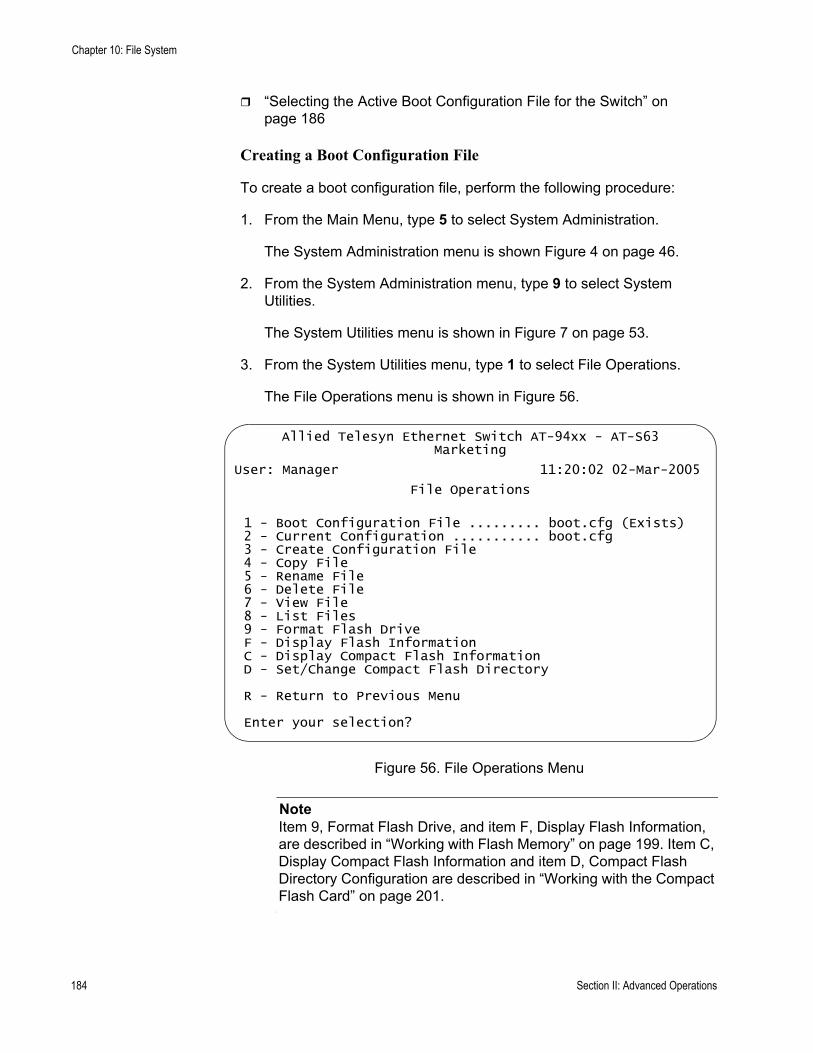
Chapter 10: File System
“Selecting the Active Boot Configuration File for the Switch” on page 186
Creating a Boot Configuration File
To create a boot configuration file, perform the following procedure:
1. From the Main Menu, type 5 to select System Administration.
The System Administration menu is shown Figure 4 on page 46.
2. From the System Administration menu, type 9 to select System Utilities.
The System Utilities menu is shown in Figure 7 on page 53.
3. From the System Utilities menu, type 1 to select File Operations.
The File Operations menu is shown in Figure 56.
Figure 56. File Operations Menu
NoteItem 9, Format Flash Drive, and item F, Display Flash Information, are described in “Working with Flash Memory” on page 199. Item C, Display Compact Flash Information and item D, Compact Flash Directory Configuration are described in “Working with the Compact Flash Card” on page 201.
Allied Telesyn Ethernet Switch AT-94xx - AT-S63Marketing
User: Manager 11:20:02 02-Mar-2005
File Operations
1 - Boot Configuration File ......... boot.cfg (Exists)2 - Current Configuration ........... boot.cfg3 - Create Configuration File4 - Copy File5 - Rename File6 - Delete File7 - View File8 - List Files9 - Format Flash DriveF - Display Flash InformationC - Display Compact Flash InformationD - Set/Change Compact Flash Directory
R - Return to Previous Menu
Enter your selection?
184 Section II: Advanced Operations
AT-S63 Management Software Menus Interface User’s Guide
4. From the File Operations menu, type 3 to select Create Configuration File.
The following prompt is displayed:
Enter the file name:
5. Enter a file name for the new boot configuration file.
The file name can be up to 16 alphanumeric characters. Spaces are allowed. The filename must include the extension “.cfg”. See “File Naming Conventions” on page 180.
NoteIf a filename already exists, the system displays a message asking if you want to overwrite the existing file name.
NoteYou cannot name a boot configuration file “default.cfg.” This file name is reserved by the switch.
6. Type 1 to select Boot Configuration File.
The following prompt is displayed:
Enter the file name:
7. Enter the same file name that you entered in Step 5.
This makes your new boot configuration file the active file on the switch. To save any changes that you made to the switch’s parameter settings, type R until you return to the Main Menu. Then type S to select Save Configuration Changes.
The file name is now displayed following selection 1 in the File Operations menu. The file name should be followed by “Exist”, meaning that the file exists in the switch’s file system. If “Not Found” is displayed instead, the file is created the next time you select Save Configuration Changes from the Main Menu.
Configuring the Switch’s Parameter Settings
After you create a boot configuration file and designate it as the active boot configuration file on the switch, you should now configure the switch’s parameter settings by making those changes that you want the new boot configuration file to contain. Then, save your changes to the boot configuration file by returning to the Main Menu and typing S to select Save Configuration Changes. Failure to save your changes means that the boot configuration file does not contain the new parameter settings.
Section II: Advanced Operations 185
Chapter 10: File System
NoteOnly the active boot configuration file is changed when you select the Save Configuration Changes option in the Main Menu. No other boot configuration files that are stored on the switch are altered.
Selecting the Active Boot Configuration File for the Switch
You have now created the boot configuration file, made the necessary changes to the switch’s parameter settings, and saved the changes. If you want the switch to use this new boot configuration file the next time you reset or power cycle the switch, no further steps are necessary. The new boot configuration file is already the active boot file on the device.
But if you want the switch to use a different file as the active boot configuration file, then perform the procedure in “Setting the Active Boot Configuration File” on page 186.
Setting the ActiveBoot
ConfigurationFile
This procedure selects the active boot configuration file on the switch. The switch uses the active boot configuration file to set its parameter settings the next time the unit is reset or power cycled. You can select a boot configuration file that you created on the switch or one that you downloaded onto the switch from another switch.
NoteThe active boot configuration file is updated whenever you select the Save Configuration Changes from the Main Menu.
To select the active boot configuration file for the switch, perform the following procedure:
1. From the Main Menu, type 5 to select System Administration.
The System Administration menu is shown Figure 4 on page 46.
2. From the System Administration menu, type 9 to select System Utilities.
The System Utilities menu is shown in Figure 7 on page 53.
3. From the System Utilities menu, type 1 to select File Operations.
The File Operations menu is shown in Figure 56 on page 184.
4. From the File Operations menu, type 1 to select Boot Configuration File.
The following prompt is displayed:
Enter the file name:
186 Section II: Advanced Operations
AT-S63 Management Software Menus Interface User’s Guide
5. Enter the file name of the boot configuration file that you want the switch to use the next time it is reset or power cycled.
The file name is displayed following selection 1 in the File Operations menu. The file name should be followed by “Exist”, which means that the file exists in the switch’s file system. In the future, the switch uses the newly selected boot configuration file whenever you reset the unit, unless you designate another boot configuration file as the active boot file.
NoteIf “Not Found” appears, the file does not exist. If you reboot the switch using a nonexistent boot configuration file, the switch is reset to its factory default settings.
6. To activate the parameter settings in the newly selected boot configuration file, reset or power cycle the switch.
Viewing a BootConfiguration
File
Use the following procedure to view the contents of a boot configuration file. (To display the names of the boot configuration files on the switch, see “Displaying System Files” on page 195.)
To view the contents of a boot configuration file, perform the following procedure:
1. From the Main Menu, type 5 to select System Administration.
The System Administration menu is shown Figure 4 on page 46.
2. From the System Administration menu, type 9 to select System Utilities.
The System Utilities menu is shown in Figure 7 on page 53.
3. From the System Utilities menu, type 1 to select File Operations.
The File Operations menu is shown in Figure 56 on page 184.
4. From the File Operations menu, type 7 to select View File.
The following prompt is displayed:
Enter file name:
5. Enter the name of the boot configuration file you want to view.
Section II: Advanced Operations 187
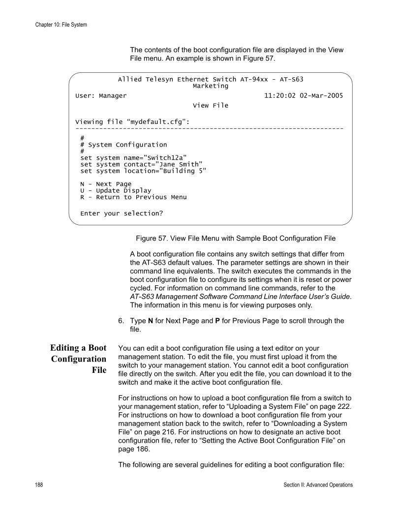
Chapter 10: File System
The contents of the boot configuration file are displayed in the View File menu. An example is shown in Figure 57.
Figure 57. View File Menu with Sample Boot Configuration File
A boot configuration file contains any switch settings that differ from the AT-S63 default values. The parameter settings are shown in their command line equivalents. The switch executes the commands in the boot configuration file to configure its settings when it is reset or power cycled. For information on command line commands, refer to the AT-S63 Management Software Command Line Interface User’s Guide. The information in this menu is for viewing purposes only.
6. Type N for Next Page and P for Previous Page to scroll through the file.
Editing a BootConfiguration
File
You can edit a boot configuration file using a text editor on your management station. To edit the file, you must first upload it from the switch to your management station. You cannot edit a boot configuration file directly on the switch. After you edit the file, you can download it to the switch and make it the active boot configuration file.
For instructions on how to upload a boot configuration file from a switch to your management station, refer to “Uploading a System File” on page 222. For instructions on how to download a boot configuration file from your management station back to the switch, refer to “Downloading a System File” on page 216. For instructions on how to designate an active boot configuration file, refer to “Setting the Active Boot Configuration File” on page 186.
The following are several guidelines for editing a boot configuration file:
Allied Telesyn Ethernet Switch AT-94xx - AT-S63Marketing
User: Manager 11:20:02 02-Mar-2005
View File
Viewing file “mydefault.cfg”: --------------------------------------------------------------------
## System Configuration#set system name="Switch12a"set system contact="Jane Smith"set system location="Building 5"
N - Next PageU - Update DisplayR - Return to Previous Menu
Enter your selection?
188 Section II: Advanced Operations
AT-S63 Management Software Menus Interface User’s Guide
The text editor must be able to store the file as ASCII text. Do not insert special formatting codes, such as boldface or italics, into a boot configuration file.The boot configuration file must contain AT-S63 command line commands. You enter the commands you want the switch to perform when reset or power cycled. For a description of the commands, refer to the AT-S63 Management Software Command Line Interface User’s Guide.A boot configuration file is divided into sections with each section devoted to the commands for a particular purpose. For example, the VLAN Configuration section should only contain commands for creating VLANs or for setting the VLAN mode.Each command must start flush left.To comment out a command so that the switch does not perform it, precede the command with the pound symbol (#).You should test the commands manually by entering them at a command line prompt before you insert them into a boot configuration file. This helps ensure that you understand the syntax and parameters of the commands and that the commands produce the desired results.To troubleshoot a boot configuration file, start a local management session with the switch and reset the device. Messages displayed on the screen during the boot up and boot configuration process indicate that the line in the boot configuration file that contains the error.
Section II: Advanced Operations 189
Chapter 10: File System
Copying a System File
To copy a system file, perform the following procedure:
1. From the Main Menu, type 5 to select System Administration.
The System Administration menu is shown Figure 4 on page 46.
2. From the System Administration menu, type 9 to select System Utilities.
The System Utilities menu is shown in Figure 7 on page 53.
3. From the System Utilities menu, type 1 to select File Operations.
The File Operations menu is shown in Figure 56 on page 184.
4. From the File Operations menu, type 4 to select Copy File.
NoteSelecting Copy File does not allow you to overwrite files.
The following prompt is displayed:
Enter the source file name:
NoteFiles with the extension UKF are encryption key pairs. These files cannot be copied, renamed, or deleted from the file system. To delete a key pair from the switch, refer to “Deleting an Encryption Key” on page 709.
5. Enter the name of the file you want to copy. If the file is located on a compact flash card, precede the filename with “cflash:”
The following prompt is displayed:
Enter the destination file name:
6. Enter the new file name.
You can enter a file name of up to 16 alphanumeric characters, followed by a 3 letter extension. You must keep the same extension. If the file is located on a compact flash card, precede the filename with “cflash:”
The following message is displayed:
190 Section II: Advanced Operations

AT-S63 Management Software Menus Interface User’s Guide
Please wait...Press any key ...
7. Press any key to return to the File Operations menu.
Section II: Advanced Operations 191
Chapter 10: File System
Renaming a System File
To rename a system file, perform the following procedure:
1. From the Main Menu, type 5 to select System Administration.
The System Administration menu is shown Figure 4 on page 46.
2. From the System Administration menu, type 9 to select System Utilities.
The System Utilities menu is shown in Figure 7 on page 53.
3. From the System Utilities menu, type 1 to select File Operations.
The File Operations menu is shown in Figure 56 on page 184.
4. From the File Operations menu, type 5 to select Rename File.
The following prompt is displayed:
Enter the source file name:
NoteFiles with the extension UKF are encryption key pairs. These files cannot be copied, renamed, or deleted from the file system. To delete a key pair from the switch, refer to “Deleting an Encryption Key” on page 709.
5. Enter the name of the file you want to rename. If the file is located on a compact flash card, precede the filename with “cflash:”
The following prompt is displayed:
Enter the destination file name:
NoteThe source and destinations be on the same device, either flash memory or a compact flash card.
6. Enter the new name for the file.
You can enter a file name of up to 16 alphanumeric characters, followed by a 3 letter extension. You must keep the same extension. If the file is located on a compact flash card, precede the filename with “cflash:”
The following message is displayed:
192 Section II: Advanced Operations

AT-S63 Management Software Menus Interface User’s Guide
Please wait...Press any key ...
Press any key to return to the File Operations menu.
Section II: Advanced Operations 193

Chapter 10: File System
Deleting a System File
To delete a system file, perform the following procedure:
1. From the Main Menu, type 5 to select System Administration.
The System Administration menu is shown Figure 4 on page 46.
2. From the System Administration menu, type 9 to select System Utilities.
The System Utilities menu is shown in Figure 7 on page 53.
3. From the System Utilities menu, type 1 to select File Operations.
The File Operations menu is shown in Figure 56 on page 184.
4. From the File Operations menu, type 6 to select Delete File.
The following prompt is displayed:
Enter file name to be deleted:
NoteFiles with the extension UKF are encryption key pairs. These files cannot be copied, renamed, or deleted from the file system. To delete a key pair from the switch, refer to “Deleting an Encryption Key” on page 709.
5. Enter the name of the file you want to delete. If the file is located on a compact flash card, precede the filename with “cflash:”
The following prompt is displayed:
Please wait...Press any key ...
6. Press any key to return to the File Operations menu.
NoteDeleting the boot configuration file that is acting as the active boot configuration file causes the switch to use its default settings the next time you reboot or power cycle the switch, unless you select another active boot configuration file. For instructions on how to change the active boot configuration file, see “Setting the Active Boot Configuration File” on page 186.
194 Section II: Advanced Operations

AT-S63 Management Software Menus Interface User’s Guide
Displaying System Files
Use this procedure to display a list of the system files currently stored either in the flash memory of the switch or on a compact flash card. For information about shortcuts for specifying file names, see “File Naming Conventions” on page 180.
Listing All Files To display a list of the system files stored in flash memory as well as on a compact flash card (if the switch supports this and a compact flash card is inserted in the slot), perform the following procedure:
1. From the Main Menu, type 5 to select System Administration.
The System Administration menu is shown Figure 4 on page 46.
2. From the System Administration menu, type 9 to select System Utilities.
The System Utilities menu is shown in Figure 7 on page 53.
3. From the System Utilities menu, type 1 to select File Operations.
The File Operations menu is shown in Figure 56 on page 184.
4. From the File Operations Menu, type 8 to select List Files.
The following prompt is displayed:
Enter file name pattern to list:
5. Enter a boot configuration file name or pattern using the wildcard “*”. Below are examples of how to use the wildcard to display different files.
To display a list of all the files stored both in flash memory and on a compact flash card in the same switch, enter:
*.*
Section II: Advanced Operations 195

Chapter 10: File System
An example of this display is shown in Figure 58.
Figure 58. List Files Menu for Flash Memory and a Compact Flash Card
NoteIf the switch does not support a compact flash card, only the files in flash memory are displayed. To display only the files in flash memory, precede the file name with “flash:”.
To display a list of the certificate files, enter:
*.cer
To display a list of the boot configuration files, enter:
*.cfg
To display a list of the key files, enter:
*.key
To display a list of the files that begin with the letter t, enter:
t*.*
The columns in the List Files table are described below. This information is for viewing purposes only.
File NameName of the system file.
Allied Telesyn Ethernet Switch AT-94xx - AT-S63Marketing
User: Manager 11:20:02 02-Mar-2005
List Files
File Name Device Size (Bytes) Last Modified -------------------------------------------------------------default.cfg flash 805 01/10/2002 12:01:16boot.cfg flash 1249 10/24/2003 16:50:40newcfg.cg flash 1082 07/12/2003 16:59:06serverkey150.key flash 768 11/30/2003 19:17:35ProdSw.cer flash 1024 11/30/2003 20:38:20ProdSw2.cer flash 560 12/11/2003 20:56:13
Compact Flash Current Directory is: \dcim cflash <dir> 12/17/2004 12:51:44
U - Update DisplayR - Return to Previous Menu
Enter your selection?
196 Section II: Advanced Operations
AT-S63 Management Software Menus Interface User’s Guide
DeviceThe device type, either “flash” for flash memory or “cflash” for compact flash card.
SizeSize of the file, in bytes.
Last ModifiedThe time the file was created or last modified, in the following date and time format: month/day/year hours:minutes:seconds.
Listing Files onthe Compact
Flash Card
To view the files on the compact flash card, perform the following procedure:
1. From the Main Menu, type 5 to select System Administration.
The System Administration menu is shown Figure 4 on page 46.
2. From the System Administration menu, type 9 to select System Utilities.
The System Utilities menu is shown in Figure 7 on page 53.
3. From the System Utilities menu, type 1 to select File Operations.
The File Operations menu is shown in Figure 56 on page 184.
4. From the File Operations Menu, type 8 to select List Files.
The following prompt is displayed:
Enter file name pattern to list:
5. To list the files only on the compact flash card, enter:
cflash *.*
NoteYou can also specify a particular file type, as described “File Naming Conventions” on page 180.
Section II: Advanced Operations 197

Chapter 10: File System
The system displays files on the compact flash card, as shown in Figure 59.
Figure 59. List Files Menu for a Compact Flash Card
Allied Telesyn Ethernet Switch AT-94xx - AT-S63Marketing
User: Manager 11:20:02 02-Mar-2005
List Files
File Name Device Size (Bytes) Last Modified -------------------------------------------------------------dcim\ cflash <dir> 01/10/2005 12:01:16boot.cfg cflash 1249 10/24/2005 16:50:40newcfg.cg cflash 1082 07/12/2005 16:59:06serverkey150.key cflash 768 11/30/2005 19:17:35ProdSw.cer cflash 1024 11/30/2005 20:38:20ProdSw2.cer cflash 560 12/11/2005 20:56:13
U - Update DisplayR - Return to Previous Menu
Enter your selection?
198 Section II: Advanced Operations
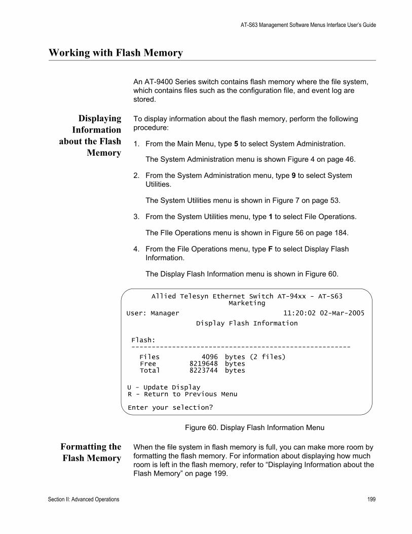
AT-S63 Management Software Menus Interface User’s Guide
Working with Flash Memory
An AT-9400 Series switch contains flash memory where the file system, which contains files such as the configuration file, and event log are stored.
DisplayingInformation
about the FlashMemory
To display information about the flash memory, perform the following procedure:
1. From the Main Menu, type 5 to select System Administration.
The System Administration menu is shown Figure 4 on page 46.
2. From the System Administration menu, type 9 to select System Utilities.
The System Utilities menu is shown in Figure 7 on page 53.
3. From the System Utilities menu, type 1 to select File Operations.
The FIle Operations menu is shown in Figure 56 on page 184.
4. From the File Operations menu, type F to select Display Flash Information.
The Display Flash Information menu is shown in Figure 60.
Figure 60. Display Flash Information Menu
Formatting theFlash Memory
When the file system in flash memory is full, you can make more room by formatting the flash memory. For information about displaying how much room is left in the flash memory, refer to “Displaying Information about the Flash Memory” on page 199.
Allied Telesyn Ethernet Switch AT-94xx - AT-S63Marketing
User: Manager 11:20:02 02-Mar-2005
Display Flash Information
Flash: ------------------------------------------------------
Files 4096 bytes (2 files)Free 8219648 bytesTotal 8223744 bytes
U - Update DisplayR - Return to Previous Menu
Enter your selection?
Section II: Advanced Operations 199
Chapter 10: File System
CautionWhen you format the flash memory, ALL files including the default configuration and boot files are lost. This includes encryption keys, certificates, configuration files, and all other special files. To remove selected files, use the procedure in “Deleting a System File” on page 194.
To format the flash memory, perform the following procedure:
1. From the Main Menu, type 5 to select System Administration.
The System Administration menu is shown in Figure 4 on page 46.
2. From the System Administration menu, type 9 to select System Utilities.
The System Utilities menu is shown in Figure 7 on page 53.
3. From the System Utilities menu, type 1 to select File Operations.
The FIle Operations menu is shown in Figure 56 on page 184.
4. From the File Operations menu, type 9 to select Format Flash Drive.
The following prompt is displayed:
This command will format the flash drive and requires a switch reboot.Do you want to continue? [Yes/No] ->
5. To continue, type Y for Yes; to stop the formatting, type N for No.
If you choose Y, the flash memory is formatted and the switch reboots.
200 Section II: Advanced Operations
AT-S63 Management Software Menus Interface User’s Guide
Working with the Compact Flash Card
Some AT-9400 Series switches contain a compact flash card slot, into which you can put a compact flash card. You can then copy files such as configuration files onto the compact flash card, take the card to other switches that have compact flash card slots, and copy files from the compact flash card to that switch through a local connection. The compact flash card is also a medium onto which you can store system files as backups.
DisplayingCompact Flash
Card Information
To display information about the compact flash card, perform the following procedure:
1. From the Main Menu, type 5 to select System Administration.
The System Administration menu is shown Figure 4 on page 46.
2. From the System Administration menu, type 9 to select System Utilities.
The System Utilities menu is shown in Figure 7 on page 53.
3. From the System Utilities menu, type 1 to select File Operations.
The FIle Operations menu is shown in Figure 56 on page 184.
4. From the File Operations menu, type C to select Display Compact Flash Information.
The Display Compact Flash Information menu is shown in Figure 61.
Section II: Advanced Operations 201
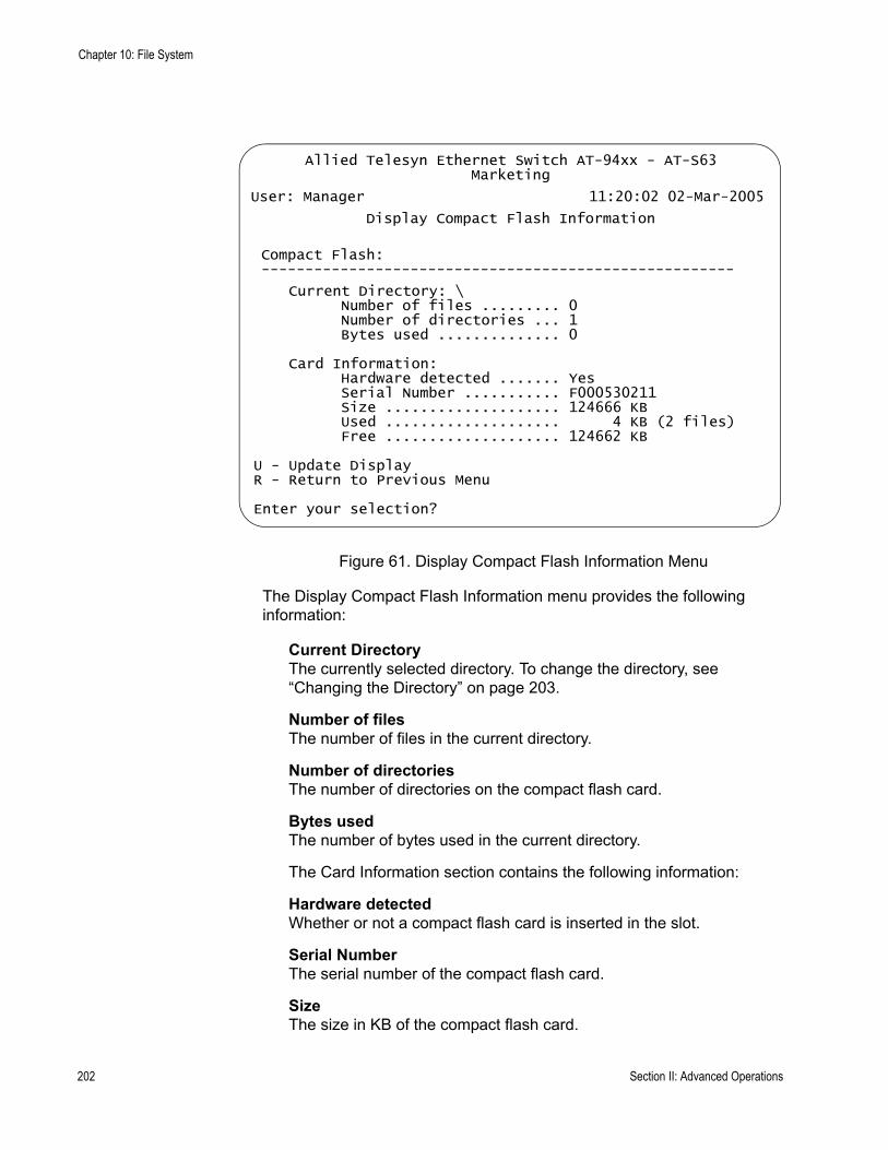
Chapter 10: File System
Figure 61. Display Compact Flash Information Menu
The Display Compact Flash Information menu provides the following information:
Current DirectoryThe currently selected directory. To change the directory, see “Changing the Directory” on page 203.
Number of filesThe number of files in the current directory.
Number of directoriesThe number of directories on the compact flash card.
Bytes usedThe number of bytes used in the current directory.
The Card Information section contains the following information:
Hardware detectedWhether or not a compact flash card is inserted in the slot.
Serial NumberThe serial number of the compact flash card.
SizeThe size in KB of the compact flash card.
Allied Telesyn Ethernet Switch AT-94xx - AT-S63Marketing
User: Manager 11:20:02 02-Mar-2005
Display Compact Flash Information
Compact Flash: ------------------------------------------------------
Current Directory: \Number of files ......... 0Number of directories ... 1Bytes used .............. 0
Card Information:Hardware detected ....... YesSerial Number ........... F000530211Size .................... 124666 KBUsed .................... 4 KB (2 files)Free .................... 124662 KB
U - Update DisplayR - Return to Previous Menu
Enter your selection?
202 Section II: Advanced Operations
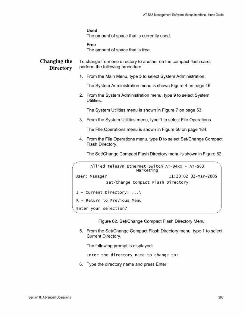
AT-S63 Management Software Menus Interface User’s Guide
UsedThe amount of space that is currently used.
FreeThe amount of space that is free.
Changing theDirectory
To change from one directory to another on the compact flash card, perform the following procedure:
1. From the Main Menu, type 5 to select System Administration.
The System Administration menu is shown Figure 4 on page 46.
2. From the System Administration menu, type 9 to select System Utilities.
The System Utilities menu is shown in Figure 7 on page 53.
3. From the System Utilities menu, type 1 to select File Operations.
The FIle Operations menu is shown in Figure 56 on page 184.
4. From the File Operations menu, type D to select Set/Change Compact Flash Directory.
The Set/Change Compact Flash Directory menu is shown in Figure 62.
Figure 62. Set/Change Compact Flash Directory Menu
5. From the Set/Change Compact Flash Directory menu, type 1 to select Current Directory.
The following prompt is displayed:
Enter the directory name to change to:
6. Type the directory name and press Enter.
Allied Telesyn Ethernet Switch AT-94xx - AT-S63Marketing
User: Manager 11:20:02 02-Mar-2005
Set/Change Compact Flash Directory
1 - Current Directory: ...\
R - Return to Previous Menu
Enter your selection?
Section II: Advanced Operations 203

Chapter 10: File System
204 Section II: Advanced Operations

Chapter 11
File Downloads and Uploads
This chapter contains the procedures for downloading a new AT-S63 image file onto the switch. This chapter also contains the procedures for uploading and downloading system files, such as a boot configuration file, from the file system in the switch. The procedures in this chapter are:
“Downloading the AT-S63 Image File onto a Switch” on page 206“Downloading an AT-S63 Image File Switch to Switch” on page 212“Downloading an AT-S63 Configuration File Switch to Switch” on page 214“Downloading a System File” on page 216“Uploading a System File” on page 222
NoteFor instructions on how to obtain the latest version of the AT-S63 management software, refer to “Management Software Updates” on page 26.
Section II: Advanced Operations 205

Chapter 11: File Downloads and Uploads
Downloading the AT-S63 Image File onto a Switch
This section contains two procedures for downloading a new AT-S63 image file onto the switch. They are:
“Downloading the AT-S63 Image from a Local Management Session” on page 207“Downloading the AT-S63 Image from a Telnet Management Session” on page 210
Please note the following before you begin either procedure:
You can download a new AT-S63 image file onto the switch from either a local or Telnet management session. You cannot perform this procedure from a web browser management session.You can use Xmodem or TFTP to download the image file from a local management session.You must use TFTP to download the image file from a Telnet management session.To use TFTP, there must be a node on your network that contains the TFTP server software, and the new AT-S63 image file must be stored on that node.If you are using TFTP, you should start the TFTP server before you begin the download procedure.The AT-S63 image file contains the bootloader for the switch. You cannot load the image file and bootloader separately.Installing a new AT-S63 software image does not change the current configuration of a switch (for instance, IP address, subnet mask, and virtual LANs). To return a switch to its default configuration values, refer to “Returning the AT-S63 Management Software to the Factory Default Values” on page 67.
CautionThe switch stops forwarding Ethernet traffic after it has downloaded the image file and begun to initialize the software. Some network traffic may be lost.
The following procedures assume that you have already obtained the new software from Allied Telesyn and stored it on the management station from which you will be performing the procedure, or on the TFTP server.
206 Section II: Advanced Operations
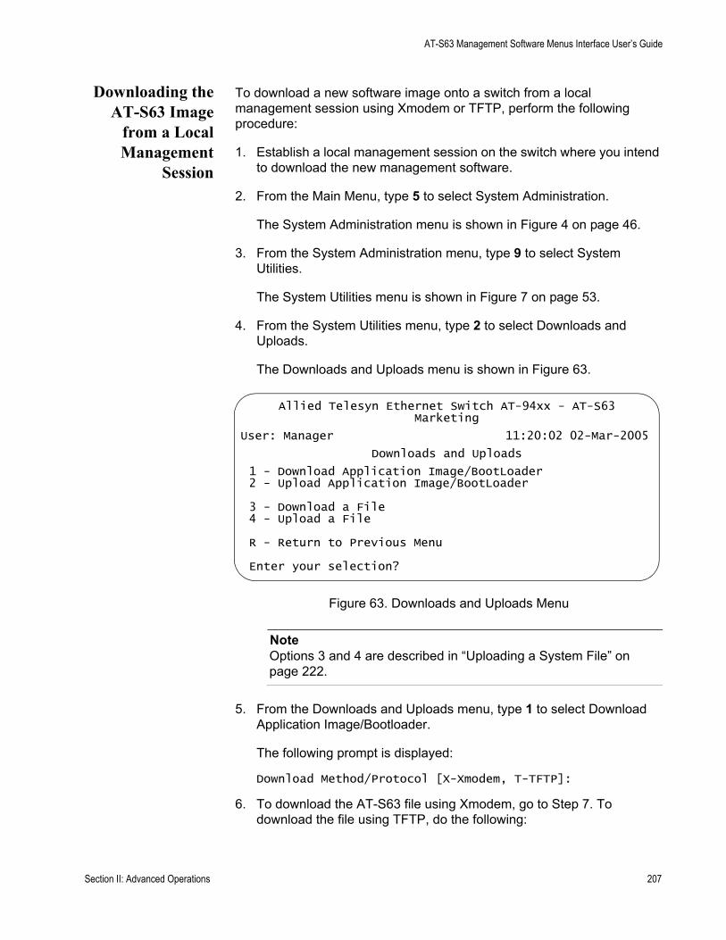
AT-S63 Management Software Menus Interface User’s Guide
Downloading theAT-S63 Image
from a LocalManagement
Session
To download a new software image onto a switch from a local management session using Xmodem or TFTP, perform the following procedure:
1. Establish a local management session on the switch where you intend to download the new management software.
2. From the Main Menu, type 5 to select System Administration.
The System Administration menu is shown in Figure 4 on page 46.
3. From the System Administration menu, type 9 to select System Utilities.
The System Utilities menu is shown in Figure 7 on page 53.
4. From the System Utilities menu, type 2 to select Downloads and Uploads.
The Downloads and Uploads menu is shown in Figure 63.
Figure 63. Downloads and Uploads Menu
NoteOptions 3 and 4 are described in “Uploading a System File” on page 222.
5. From the Downloads and Uploads menu, type 1 to select Download Application Image/Bootloader.
The following prompt is displayed:
Download Method/Protocol [X-Xmodem, T-TFTP]:
6. To download the AT-S63 file using Xmodem, go to Step 7. To download the file using TFTP, do the following:
Allied Telesyn Ethernet Switch AT-94xx - AT-S63Marketing
User: Manager 11:20:02 02-Mar-2005
Downloads and Uploads
1 - Download Application Image/BootLoader2 - Upload Application Image/BootLoader
3 - Download a File4 - Upload a File
R - Return to Previous Menu
Enter your selection?
Section II: Advanced Operations 207
Chapter 11: File Downloads and Uploads
a. Type T.
The following prompt is displayed:
TFTP Server IP address:
b. Enter the IP address of the TFTP server.
The following prompt is displayed:
Remote File Name:
c. Enter the directory path and file name of the AT-S63 image file stored on the TFTP server.
The following message is displayed:
Getting the file from Remote TFTP Server - Please wait ...
d. If you have not already done so, start the TFTP server software.
After the switch has downloaded the image file, the following message is displayed:
File received successfully!
NoteThe switch validates the file and then begins the initialization process of writing the image to flash. The switch does not forward any network traffic during the initialization process. After the management software is initialized, the switch automatically resets.
7. To download a file using Xmodem, type X at the prompt displayed in Step 5.
The following prompt is displayed:
You are going to invoke the Xmodem download utility.Do you wish to continue? [Yes/No]
Note: Please select 1K Xmodem protocol for faster download.
NoteThe transfer protocol must be Xmodem or 1K Xmodem.
8. Type Y for Yes.
The prompt “Downloading” is displayed.
208 Section II: Advanced Operations

AT-S63 Management Software Menus Interface User’s Guide
9. Begin the file transfer.
Steps 10 through 13 illustrate how you download a file using the Hilgraeve HyperTerminal program.
10. From the HyperTerminal main window, select Send File from the Transfer menu, as shown in Figure 64.
Figure 64. HyperTerminal Window
The Send File window is shown in Figure 65.
Figure 65. Send File Window
11. Click Browse and specify the location and file to be downloaded onto the switch.
12. Click in the Protocol field and select as the transfer protocol either Xmodem or, for a faster download, 1K Xmodem.
13. Click Send.
The software immediately begins downloading onto the switch. The Xmodem File Send window in Figure 66 displays the current status of
Section II: Advanced Operations 209

Chapter 11: File Downloads and Uploads
the software download. The download process takes several minutes to complete.
Figure 66. XModem File Send Window
NoteAfter the switch has downloaded the new image, it begins to initialize the software, a process that takes approximately one minute to complete. The switch does not forward any network traffic during the initialization process. After the management software is initialized, the switch automatically resets.
Downloading theAT-S63 Imagefrom a TelnetManagement
Session
To download a new software image onto a switch from a Telnet management session using TFTP, perform the following procedure:
1. Establish a Telnet management session on the switch where you intend to download the new management software.
2. From the Main Menu, type 5 to select System Administration.
The System Administration menu is shown in Figure 4 on page 46.
3. From the System Administration menu, type 9 to select System Utilities.
The System Utilities menu is shown in Figure 7 on page 53.
4. From the System Utilities menu, type 2 to select Downloads and Uploads.
210 Section II: Advanced Operations

AT-S63 Management Software Menus Interface User’s Guide
The Downloads and Uploads menu is shown in Figure 63 on page 207.
5. From the Downloads and Uploads menu, type 1 to select Download Application Image/Bootloader.
The following prompt is displayed:
Only TFTP downloads are available for a Telnet access
TFTP Server IP address:
6. Enter the IP address of the TFTP server.
The following prompt is displayed:
Remote File Name:
7. Enter the directory path and file name of the image file or configuration file that you want to download.
The following message is displayed:
Getting the file from Remote TFTP Server - Please wait ...
8. If you have not already done so, start the TFTP server software.
After the switch has downloaded the image file, the following message is displayed:
File received successfully!
NoteThe switch validates the file and then begins the initialization process of writing the image to flash. The switch does not forward any network traffic during the initialization process. After the management software is initialized, the switch automatically resets.
Section II: Advanced Operations 211
Chapter 11: File Downloads and Uploads
Downloading an AT-S63 Image File Switch to Switch
The previous section contained procedures for downloading an AT-S63 software image onto a switch from a local or Telnet management session. The procedure in this section explains how to download an AT-S63 software image from one AT-9400 Series switch to another AT-9400 Series switch.
This procedure is useful in networks that contain a large number of AT-9400 Series switches. After you have updated the software on the master switch of an enhanced stack, you can instruct the master switch to automatically upgrade the other AT-9400 Series switches in the enhanced stack.
NoteYou can perform this procedure from a local or Telnet management session.
To download a management software image from a master switch to other switches in the same enhanced stack, perform the following procedure:
1. From the Main Menu, type 9 to select Enhanced Stacking.
The Enhanced Stacking menu is shown in Figure 21 on page 94.
2. From the Enhanced Stacking menu, type 2 to select Stacking Services.
NoteThe “2 - Stacking Services” selection is available only on master switches.
The Stacking Services menu is shown in Figure 22 on page 95.
3. From the Stacking Services menu, type 1 to select Get/Refresh List of Switches. The master switch polls the network for all enhanced stacking switches in the subnet and displays the switches in the Stacking Services menu.
4. Type 4 to select Download Image/Bootloader.
The following prompt is displayed:
Enter the list of switches ->
5. Enter the number (Num column in the menu) of the AT-9400 Series switch whose software you want to update. You can specify more than one switch at a time (for example, 2,4,5).
212 Section II: Advanced Operations
AT-S63 Management Software Menus Interface User’s Guide
NoteYou cannot download AT-S63 software onto any type of enhanced stacking switch other than AT-9400 Series switches.
The following prompt is displayed:
Do you want to show remote switch burning flash -> [Yes/No]
6. You can respond with Yes or No to this prompt. It does not affect the download.
The following prompt is displayed:
Do you want confirmation before downloading each switch -> [Yes/No]
7. If you answer Yes to this prompt, the management software prompts you with a confirmation message before upgrading a switch. If you answer No, the management software does not display a confirmation prompt before downloading.
The management software begins the download. The management software notifies you when the download is complete.
CautionAfter a switch image file has been downloaded, the switch must decompress it and write it to flash, a process that takes several minutes to complete. Do not reset or power off the unit while it is decompressing the file. After the file has been decompressed, the switch automatically resets.
Section II: Advanced Operations 213
Chapter 11: File Downloads and Uploads
Downloading an AT-S63 Configuration File Switch to Switch
This procedure explains how to download the active boot configuration file on the master AT-9400 Series switch to another AT-9400 Series switch in an enhanced stack. For an explanation of the boot configuration file, refer to “Working with Boot Configuration Files” on page 183.
NoteYou can perform this procedure from a local or Telnet management session.
To download the active boot configuration file on the master switch to another switch in an enhanced stack, perform the following procedure:
1. From the Main Menu, type 9 to select Enhanced Stacking.
The Enhanced Stacking menu is shown in Figure 21 on page 94.
2. From the Enhanced Stacking menu, type 2 to select Stacking Services.
NoteThe “2 - Stacking Services” selection is available only on master switches.
The Stacking Services menu is shown in Figure 22 on page 95.
3. From the Stacking Services menu, type 1 to select Get/Refresh List of Switches. The master switch polls the network for all enhanced stacking switches in the subnet and displays the switches in the Stacking Services menu.
4. Type 5 to select Download Configuration.
The following prompt is displayed:
Enter the configuration file name ->
5. Enter a name for the configuration file. This is the name under which the file will be stored on the other switch. The name can be from one to sixteen characters and must include the suffix “.cfg”.
After you have entered a name, the following prompt is displayed:
Enter the list of switches ->
214 Section II: Advanced Operations
AT-S63 Management Software Menus Interface User’s Guide
6. Enter the number (Num column in the menu) of the AT-9400 Series switch to which you want to download the configuration file. You can specify more than one switch at a time (for example, 2,4,5).
NoteYou can download an AT-9400 Series configuration file only onto other AT-9400 Series switches. Do not attempt to download the file onto any other type of enhanced stacking switch.
The following prompt is displayed:
Do you want to show remote switch burning flash -> [Yes/No]
7. You can respond with Yes or No to this prompt. It does not affect the download.
The following prompt is displayed:
Do you want confirmation before downloading each switch -> [Yes/No]
8. If you answer Yes to this prompt, the management software prompts you with a confirmation message before downloading the file to a switch. If you answer No, the management software does not display a confirmation prompt before downloading.
The management software begins the download. The management software notifies you when the download is complete.
After the configuration file is downloaded to a switch, the AT-S63 management software places the file in its file system. To make the file the active boot configuration file on the switch, refer to “Setting the Active Boot Configuration File” on page 186.
Section II: Advanced Operations 215
Chapter 11: File Downloads and Uploads
Downloading a System File
This section contains the procedures for downloading a system file from a workstation or TFTP server into the switch’s file system. You can download any of the following files:
Boot configuration filePublic encryption keyCA certificate
NoteThe CA certificate and key file are supported only on the version of AT-S63 management software that features SSL, PKI, and SSH security.
This section contains the following two procedures:
“Downloading a System File from a Local Management Session” on page 217“Downloading a System File from a Telnet Management Session” on page 220
Please note the following before you begin either procedure:
CautionDo not use this procedure to download an AT-S63 image file onto a switch. Doing so stores the image file in the switch’s file system. The switch will not be able to use the image file and the file will take up most of the available space in the file system. To download an AT-S63 image file onto a switch, see “Downloading the AT-S63 Image File onto a Switch” on page 206 or “Downloading an AT-S63 Image File Switch to Switch” on page 212.
You can download a system file from either a local or Telnet management session. You cannot perform this procedure from a web browser management session.You can use either Xmodem or TFTP to download a system file from a local management session.You must use TFTP to download a system file from a Telnet management session.To use TFTP, there must be a node on your network that contains TFTP server software.If you are using TFTP, you should start the TFTP server before you begin the download procedure.
216 Section II: Advanced Operations
AT-S63 Management Software Menus Interface User’s Guide
Downloading aSystem File from
a LocalManagement
Session
To download a system file onto a switch from a local management session using Xmodem or TFTP, perform the following procedure:
1. From the Main Menu, type 5 to select System Administration.
The System Administration menu is shown in Figure 4 on page 46.
2. From the System Administration menu, type 9 to select System Utilities.
The System Utilities menu is shown in Figure 7 on page 53.
3. From the System Utilities menu, type 2 to select Downloads and Uploads.
The Downloads and Uploads menu is shown in Figure 63 on page 207.
4. From the Downloads and Uploads menu, type 3 to select Download a File.
The following prompt is displayed:
Download Method/Protocol [X-Xmodem, T-TFTP]:
5. To download a system file using Xmodem, go to Step 7. To download a file using TFTP, do the following:
a. Type T.
The following prompt is displayed:
TFTP Server IP address:
b. Enter the IP address of the TFTP server.
The following prompt is displayed:
Remote File Name:
c. Enter the directory path and file name of the system file on the TFTP server to be downloaded to the switch. You can specify only one system file.
The following prompt is displayed:
Local File Name:
d. Enter a name for the system file. This is the name that the switch will store the file as in its file system.
The following message is displayed:
Getting the file from Remote TFTP Server - Please wait ...
Section II: Advanced Operations 217
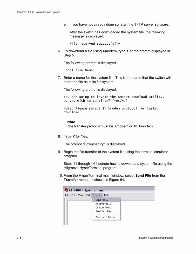
Chapter 11: File Downloads and Uploads
e. If you have not already done so, start the TFTP server software.
After the switch has downloaded the system file, the following message is displayed:
File received successfully!
6. To download a file using Xmodem, type X at the prompt displayed in Step 5.
The following prompt is displayed:
Local File Name:
7. Enter a name for the system file. This is the name that the switch will store the file as in its file system.
The following prompt is displayed:
You are going to invoke the Xmodem download utility.Do you wish to continue? [Yes/No]
Note: Please select 1K Xmodem protocol for faster download.
NoteThe transfer protocol must be Xmodem or 1K Xmodem.
8. Type Y for Yes.
The prompt “Downloading” is displayed.
9. Begin the file transfer of the system file using the terminal emulator program.
Steps 11 through 14 illustrate how to download a system file using the Hilgraeve HyperTerminal program.
10. From the HyperTerminal main window, select Send File from the Transfer menu, as shown in Figure 64.
218 Section II: Advanced Operations

AT-S63 Management Software Menus Interface User’s Guide
Figure 67. HyperTerminal Window
The Send File window is shown in Figure 65.
Figure 68. Send File Window
11. Click Browse and specify the location and system file to be downloaded onto the switch.
12. Click in the Protocol field and select as the transfer protocol either Xmodem or, for a faster download, 1K XModem.
13. Click Send.
The file immediately begins downloading onto the switch. The Xmodem File Send window in Figure 66 displays the current status of the download.
Figure 69. XModem File Send Window
Section II: Advanced Operations 219
Chapter 11: File Downloads and Uploads
The download is complete when the Downloads and Uploads menu is redisplayed.
Downloading aSystem File from
a TelnetManagement
Session
To download a system file onto a switch from a Telnet management session using TFTP, perform the following procedure:
1. Establish a Telnet management session on the switch where you intend to download the new file.
2. From the Main Menu, type 5 to select System Administration.
The System Administration menu is shown in Figure 4 on page 46.
3. From the System Administration menu, type 9 to select System Utilities.
The System Utilities menu is shown in Figure 7 on page 53.
4. From the System Utilities menu, type 2 to select Downloads and Uploads.
The Downloads and Uploads menu is shown in Figure 63 on page 207.
NoteOptions 3 and 4 in the menu are described in “Uploading a System File” on page 222.
5. From the Downloads and Uploads menu, type 3 to select Download a File.
The following prompt is displayed:
Only TFTP downloads are available for a Telnet access
TFTP Server IP address:
6. Enter the IP address of the TFTP server.
The following prompt is displayed:
Remote File Name:
7. Enter the directory path and file name of the system file you want to download.
The following message is displayed:
Getting the file from Remote TFTP Server - Please wait ...
8. If you have not already done so, start the TFTP server software.
220 Section II: Advanced Operations

AT-S63 Management Software Menus Interface User’s Guide
After the switch has downloaded the system file, the following message is displayed:
File received successfully!
Section II: Advanced Operations 221
Chapter 11: File Downloads and Uploads
Uploading a System File
You use the procedures in this section to upload a system file from a switch to a computer or TFTP server. A system file can be any of the following:
Boot configuration filePublic keyPKI certificateCertificate enrollment request
NoteThe certificate file, certificate enrollment request file, and key file are supported only on the version of AT-S63 management software that features SSL and PKI security.
This section contains the following two procedures:
“Uploading a System File from a Local Management Session” on page 222“Uploading a System File from a Telnet Management Session” on page 225
Please note the following before you begin either procedure:
You can upload a system file from either a local or Telnet management session. You cannot perform this procedure from a web browser management session.You can use either Xmodem or TFTP to upload a file from a local management session.You must use TFTP to upload a file from a Telnet management session.To use TFTP, there must be a node on your network that contains TFTP server software.If you are using TFTP, you should start the TFTP server before you begin the upload procedure.
Uploading aSystem File from
a LocalManagement
Session
To upload a system file to a workstation from a Telnet management session using Xmodem or TFTP, perform the following procedure:
1. Establish a local management session on the switch where you want to upload the system file.
2. From the Main Menu, type 5 to select System Administration.
222 Section II: Advanced Operations

AT-S63 Management Software Menus Interface User’s Guide
The System Administration menu is shown in Figure 4 on page 46.
3. From the System Administration menu, type 9 to select System Utilities.
The System Utilities menu is shown in Figure 7 on page 53.
4. From the System Utilities menu, type 2 to select Downloads and Uploads.
The Downloads and Uploads menu is shown in Figure 63 on page 207.
5. From the Downloads and Uploads menu, type 4 to select Upload a File.
The following prompt is displayed:
Upload Method/Protocol [X-Xmodem, T-TFTP]:
6. To upload a system file using Xmodem, go to Step 7. To upload a file using TFTP, do the following:
a. Type T.
The following prompt is displayed:
TFTP Server IP address:
b. Enter the IP address of the TFTP server.
The following prompt is displayed:
Remote File Name:
c. Enter the directory path where you want the system file stored on the TFTP server and a name for the file.
The following message is displayed:
Local File Name:
d. Enter the name of the system file on the switch that you want to upload to the TFTP server. You can specify only one file. You cannot use wildcards in the file name.
The following message is displayed:
Sending the file to Remote TFTP Server - Please wait ...
After the switch has uploaded the system file, the following message is displayed:
File sent successfully!
Section II: Advanced Operations 223

Chapter 11: File Downloads and Uploads
The file is now stored on the TFTP server. You can now download the file onto another AT-9400 Series switch in your network.
7. To upload a file using Xmodem, type X at the prompt displayed in Step 5.
The following message is displayed:
Local File Name:
8. Enter the name of the system file on the switch that you want to upload to your computer. You can specify only one file. You cannot use wildcards in the file name.
The following prompt is displayed:
You are going to invoke the Xmodem download utility.Do you wish to continue? [Yes/No]
Note: Please select 1K Xmodem protocol for faster download.
NoteThe transfer protocol must be Xmodem or 1K Xmodem.
9. Type Y for Yes.
The following message is displayed:
Use Hyper Terminal's 'Transfer/Receive File' option to select Protocol
Note: Please select '1K Xmodem' protocol for faster upload...
10. Begin the file transfer.
Steps 11 through 14 illustrate how you would upload a file using the Hilgraeve HyperTerminal program.
224 Section II: Advanced Operations

AT-S63 Management Software Menus Interface User’s Guide
11. From the HyperTerminal main window, select Receive File from the Transfer menu, as shown in Figure 70.
Figure 70. HyperTerminal Window
The Receive File window is shown in Figure 71.
Figure 71. Receive File Window
12. Click Browse and specify the location on your computer where you want the system file stored.
13. Click in the Protocol field and select as the transfer protocol either Xmodem or, for a faster download, 1K XModem.
14. Click Receive.
The switch uploads the file from the switch to your computer.
Uploading aSystem File from
a TelnetManagement
Session
To upload a system file from the switch using a Telnet management session and TFTP, perform the following procedure:
1. Establish a Telnet management session on the switch containing the system file you want to upload to the TFTP server.
2. From the Main Menu, type 5 to select System Administration.
The System Administration menu is shown in Figure 4 on page 46.
Section II: Advanced Operations 225

Chapter 11: File Downloads and Uploads
3. From the System Administration menu, type 9 to select System Utilities.
The System Utilities menu is shown in Figure 7 on page 53.
4. From the System Utilities menu, type 2 to select Downloads and Uploads.
The Downloads and Uploads menu is shown in Figure 63 on page 207.
5. From the Downloads and Uploads menu, type 4 to select Upload a File.
The following prompt is displayed:
Only TFTP uploads are available for a Telnet access
TFTP Server IP address:
6. Enter the IP address of the TFTP server.
The following prompt is displayed:
Remote File Name:
7. Enter the directory path where you want the system file stored on the TFTP server along with a name for the file.
The following message is displayed:
Local File Name:
8. Enter the name of the system file on the switch that you want to upload to the TFTP server. You can specify only one file. You cannot use wildcards in the file name.
The following message is displayed:
Sending the file to Remote TFTP Server - Please wait ...
After the switch has uploaded the system file, the following message is displayed:
File sent successfully!
The file is now stored on the TFTP server. You can now download the file onto another AT-9400 Series switch in your network.
226 Section II: Advanced Operations
Chapter 12
Event Log
This chapter describes the event log that allows you to view information about switch activity, and how to configure the switch to send the events to a syslog server. Sections in the chapter include:
“Event Log Overview” on page 228“Working with the Event Log” on page 230“Configuring Log Outputs” on page 241
Section II: Advanced Operations 227
Chapter 12: Event Log
Event Log Overview
A managed switch is a complex piece of computer equipment that includes both hardware and software. Multiple software features operate simultaneously, interoperating with each other and processing large amounts of network traffic. It is often difficult to determine exactly what is happening when a switch appears not to be operating normally, or what happened when the problem occurred.
A network manager’s major task is to monitor the system functions and to deal with problems as they arise. One method for doing this is to view the event messages that are generated by the switch and sent to the event log. These events can provide vital information about system activity on an AT-9400 Series switch that helps you identify and solve system problems. The event log includes the following information:
The time and date of an event The severity of an eventThe AT-S63 software module that generated the eventA description of the event
There are two ways that you can view a switch’s event messages. The first method is to view an event log. An AT-9400 Series switch has two event logs. The first is located in temporary memory and can store up to 4,000 entries. The events in this log are purged whenever you reset or power cycle the switch. The second log is located in permanent memory and has a maximum storage capacity of 2,000 entries. Events in this log are retained even when the switch is reset or power cycled. You can view either log to display the events of the switch since the unit was last reset. But to view the events that preceded a system reset, you must view the permanent event log.
The second method is to have the switch send its events to a syslog server. The syslog server functions as a central repository that stores events from many network devices simultaneously.
In order for a switch to send its events to a syslog server, you must define the syslog output. The syslog output includes the IP address of the syslog server along with other information such as the types of event messages you want the switch to send to the syslog server. You can create up to 19 output definitions on a switch. For instructions, refer to “Configuring Log Outputs” on page 241.
228 Section II: Advanced Operations

AT-S63 Management Software Menus Interface User’s Guide
NoteThe event logs, even when disabled, log all AT-S63 initialization events that occur when the switch is reset or power cycled. Any switch events that occur after AT-S63 initialization are entered into the logs only if you enable the event log feature. The default setting for the event log feature is enabled.
Section II: Advanced Operations 229

Chapter 12: Event Log
Working with the Event Log
This section contains the following procedures:
“Enabling or Disabling the Event Logs,” next“Displaying an Event Log” on page 232“Modifying the Event Log Full Action” on page 237“Clearing an Event Log” on page 238“Saving an Event Log to a File” on page 238
Enabling orDisabling the
Event Logs
This procedure explains how to enable or disable the event logs on the switch. If you disable the logs, the AT-S63 management software does not store events in its logs and does not send events to any syslog servers. The default setting for the logs is enabled.
NoteAllied Telesyn recommends setting the switch’s date and time if you enable the event log. Otherwise, entries sent to the log or to a syslog server will not have the correct time and date. For instructions, refer to “Setting the System Time” on page 58.
To enable or disable the event logs, perform the following procedure:
1. From the Main Menu, type 5 to select System Administration.
The System Administration menu is shown in Figure 4 on page 46.
2. From the System Administration menu, type 8 to select Event Log.
230 Section II: Advanced Operations

AT-S63 Management Software Menus Interface User’s Guide
The Event Log menu is shown in Figure 72.
Figure 72. Event Log Menu
3. To enable or disable event logging, type 1 to toggle Event Logging between the two options:
EnabledThe switch immediately begins to add events to the logs and send events to any defined syslog outputs. This is the default.
DisabledThe switch does not store events in the logs and does not send events to any syslog servers.
NoteYou cannot individually disable or enable the temporary and permanent event logs.
NoteWhen the event log feature is disabled and the switch is rebooted, initialization events are still logged even though the Event Log feature is disabled. The Event Logging option determines whether further events are logged.
4. After making changes, type R until you return to the Main Menu. Then type S to select Save Configuration Changes.
To display the events in the log, go to the next procedure.
Allied Telesyn Ethernet Switch AT-94xx - AT-S63Marketing
User: Manager 11:20:02 02-Mar-2005
Event Log
1 - Event Logging .......... Enabled2 - Display Output ......... Temporary (Memory)3 - Display Order .......... Chronological4 - Display Mode ........... Normal5 - Display Severity ....... E, W, I6 - Display Module ......... All
C - Clear LogL - Configure Log OutputsS - Save Log to FileV - View LogR - Return to Previous Menu
Enter your selection?
Section II: Advanced Operations 231

Chapter 12: Event Log
Displaying anEvent Log
Each time that you want to view the event log, you must choose how and what you want displayed. The event log settings are not saved.
To specify the type of events you want to display in the event log, perform the following procedure:
1. From the Main Menu, type 5 to select System Administration.
The System Administration menu is shown in Figure 4 on page 46.
2. From the System Administration menu, type 8 to select Event Log.
The Event Log menu is shown in Figure 72 on page 231.
3. To determine the source for the events, type 2 to select Display Output and toggle between two options:
Temporary (Memory)Displays the events stored in temporary memory. This selection stores approximately 4,000 events. If the switch has been running for some time without a reset or power cycle, select Temporary. This is the default.
Permanent (NVS)Displays events stored in nonvolatile memory, which stores no more than 2,000 events. If the switch was recently reset or power cycled and you want to view the events that occurred prior to the reset, select Permanent.
4. To select the order of the events in the event log, type 3 to select Display Order and toggle between two options:
ChronologicalDisplays the events in the order from the oldest event to the most recent event. This is the default.
Reverse ChronologicalDisplays the events in from the most recent event to the oldest event.
5. To select the format of the event log, type 4 to select Display Mode and toggle between two options:
NormalDisplays the time, module, severity, and description for each event. This is the default. An example of Normal mode is shown in Figure 73 on page 235.
FullDisplays the same information as Normal, plus the file name, line number, and event ID. An example of Full mode is shown in Figure 74 on page 236.
232 Section II: Advanced Operations
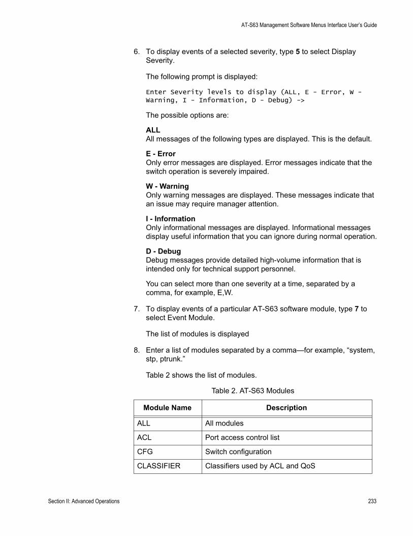
AT-S63 Management Software Menus Interface User’s Guide
6. To display events of a selected severity, type 5 to select Display Severity.
The following prompt is displayed:
Enter Severity levels to display (ALL, E - Error, W - Warning, I - Information, D - Debug) ->
The possible options are:
ALLAll messages of the following types are displayed. This is the default.
E - ErrorOnly error messages are displayed. Error messages indicate that the switch operation is severely impaired.
W - WarningOnly warning messages are displayed. These messages indicate that an issue may require manager attention.
I - InformationOnly informational messages are displayed. Informational messages display useful information that you can ignore during normal operation.
D - Debug Debug messages provide detailed high-volume information that is intended only for technical support personnel.
You can select more than one severity at a time, separated by a comma, for example, E,W.
7. To display events of a particular AT-S63 software module, type 7 to select Event Module.
The list of modules is displayed
8. Enter a list of modules separated by a comma—for example, “system, stp, ptrunk.”
Table 2 shows the list of modules.
Table 2. AT-S63 Modules
Module Name Description
ALL All modules
ACL Port access control list
CFG Switch configuration
CLASSIFIER Classifiers used by ACL and QoS
Section II: Advanced Operations 233
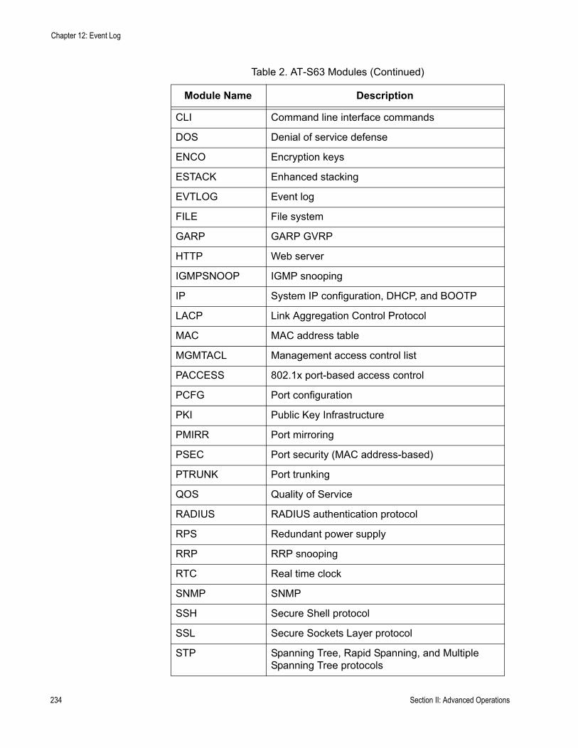
Chapter 12: Event Log
CLI Command line interface commands
DOS Denial of service defense
ENCO Encryption keys
ESTACK Enhanced stacking
EVTLOG Event log
FILE File system
GARP GARP GVRP
HTTP Web server
IGMPSNOOP IGMP snooping
IP System IP configuration, DHCP, and BOOTP
LACP Link Aggregation Control Protocol
MAC MAC address table
MGMTACL Management access control list
PACCESS 802.1x port-based access control
PCFG Port configuration
PKI Public Key Infrastructure
PMIRR Port mirroring
PSEC Port security (MAC address-based)
PTRUNK Port trunking
QOS Quality of Service
RADIUS RADIUS authentication protocol
RPS Redundant power supply
RRP RRP snooping
RTC Real time clock
SNMP SNMP
SSH Secure Shell protocol
SSL Secure Sockets Layer protocol
STP Spanning Tree, Rapid Spanning, and Multiple Spanning Tree protocols
Table 2. AT-S63 Modules (Continued)
Module Name Description
234 Section II: Advanced Operations

AT-S63 Management Software Menus Interface User’s Guide
To select specific modules, type the names separated by commas. The module names are not case sensitive. For example:
stp, psec
9. To display the event log with the settings you have chosen, type V to select View Log
Figure 73 shows an example of an event log in Normal mode.
Figure 73. Event Log Example Displayed in Normal Mode
The events are displayed in a table. The columns in the table shown in normal display mode are described below:
SYSTEM Hardware status; Manager and Operator log in and log off events.
TACACS TACACS+ authentication protocol
Telnet Telnet
TFTP TFTP
Time System time and SNTP
VLAN Port-based and tagged VLANs, and multiple VLAN modes
WATCHDOG Watchdog timer
Table 2. AT-S63 Modules (Continued)
Module Name Description
Allied Telesyn Ethernet Switch AT-94xx - AT-S63Marketing
User: Manager 11:20:02 02-Mar-2005
Event Log
S Date Time Event--------------------------------------------------------------------I 02/24/04 12:31:02 ssh: SSH server disabledI 02/24/04 12:31:02 garp: GARP initializedI 02/24/04 12:31:02 ptrunk: Trunk initialization succeeded
Temporary (Memory) Log Events 1 - 10 of 340
P - Previous Page N - Next Page F - First Page L - Last PageR - Return to Previous Menu
Enter your selection?
Section II: Advanced Operations 235
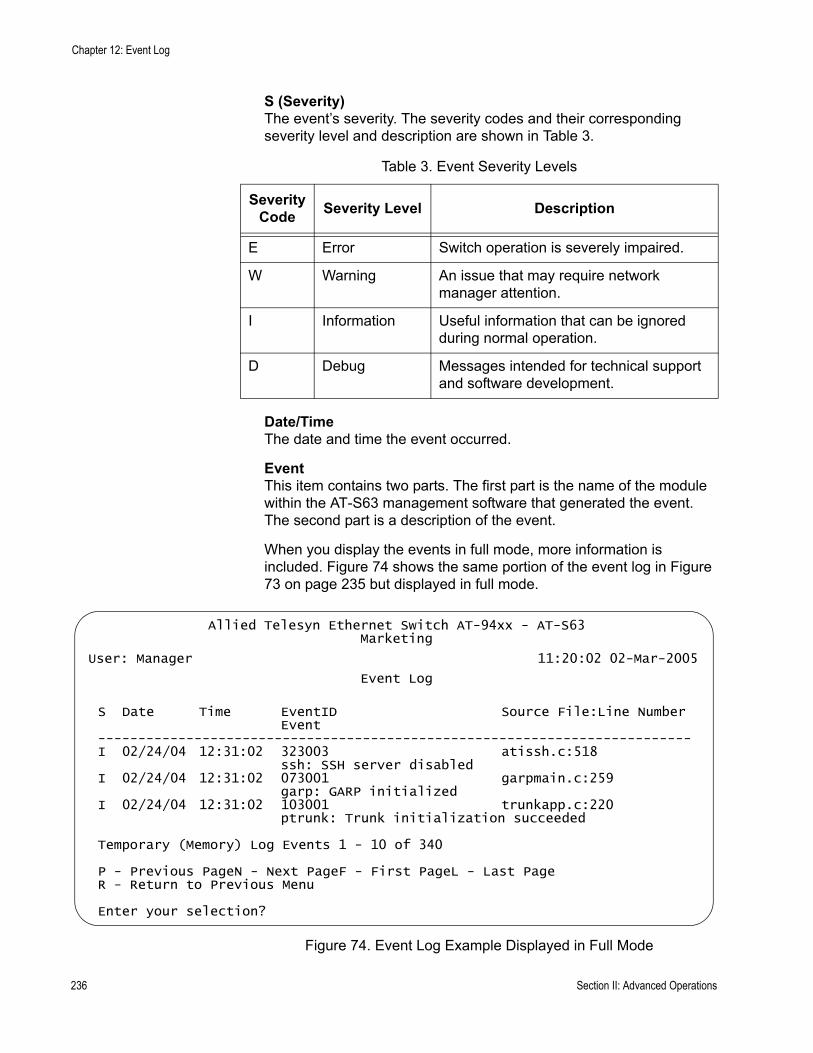
Chapter 12: Event Log
S (Severity)The event’s severity. The severity codes and their corresponding severity level and description are shown in Table 3.
Date/TimeThe date and time the event occurred.
EventThis item contains two parts. The first part is the name of the module within the AT-S63 management software that generated the event. The second part is a description of the event.
When you display the events in full mode, more information is included. Figure 74 shows the same portion of the event log in Figure 73 on page 235 but displayed in full mode.
Figure 74. Event Log Example Displayed in Full Mode
Table 3. Event Severity Levels
Severity Code Severity Level Description
E Error Switch operation is severely impaired.
W Warning An issue that may require network manager attention.
I Information Useful information that can be ignored during normal operation.
D Debug Messages intended for technical support and software development.
Allied Telesyn Ethernet Switch AT-94xx - AT-S63Marketing
User: Manager 11:20:02 02-Mar-2005
Event Log
S Date Time EventID Source File:Line NumberEvent
--------------------------------------------------------------------------I 02/24/04 12:31:02 323003 atissh.c:518
ssh: SSH server disabledI 02/24/04 12:31:02 073001 garpmain.c:259
garp: GARP initializedI 02/24/04 12:31:02 103001 trunkapp.c:220
ptrunk: Trunk initialization succeeded
Temporary (Memory) Log Events 1 - 10 of 340
P - Previous PageN - Next PageF - First PageL - Last PageR - Return to Previous Menu
Enter your selection?
236 Section II: Advanced Operations
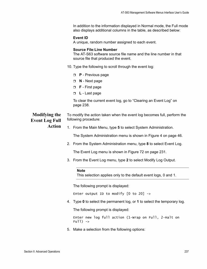
AT-S63 Management Software Menus Interface User’s Guide
In addition to the information displayed in Normal mode, the Full mode also displays additional columns in the table, as described below:
Event IDA unique, random number assigned to each event.
Source File:Line NumberThe AT-S63 software source file name and the line number in that source file that produced the event.
10. Type the following to scroll through the event log:
P - Previous pageN - Next pageF - First pageL - Last page
To clear the current event log, go to “Clearing an Event Log” on page 238.
Modifying theEvent Log Full
Action
To modify the action taken when the event log becomes full, perform the following procedure:
1. From the Main Menu, type 5 to select System Administration.
The System Administration menu is shown in Figure 4 on page 46.
2. From the System Administration menu, type 8 to select Event Log.
The Event Log menu is shown in Figure 72 on page 231.
3. From the Event Log menu, type 2 to select Modify Log Output.
NoteThis selection applies only to the default event logs, 0 and 1.
The following prompt is displayed:
Enter output ID to modify [0 to 20] ->
4. Type 0 to select the permanent log, or 1 to select the temporary log.
The following prompt is displayed:
Enter new log full action (1-Wrap on Full, 2-Halt on Full) ->
5. Make a selection from the following options:
Section II: Advanced Operations 237
Chapter 12: Event Log
1 - Wrap on FullWhen the event log reaches its maximum capacity, old entries are deleted when new entries are added. This is the default.
2- Halt on FullWhen the event log reaches its maximum capacity, the log stops adding new entries.
6. Return to the Main Menu.
Clearing anEvent Log
You can clear the event log to remove old events and start fresh. To clear the event log, perform the following procedure:
1. From the Main Menu, type 5 to select System Administration.
The System Administration menu is shown in Figure 4 on page 46.
2. From the System Administration menu, type 8 to select Event Log.
The Event Log menu is shown in Figure 72 on page 231.
3. From the Event Log menu, type C to select Clear Log.
The following prompt is displayed:
Enter output to clear (T=Temporary, P=Permanent) ->
4. To clear the temporary event log, type T. To clear the permanent event log, type P.
Saving an EventLog to a File
You can save an event log to a file to review later. The file is saved as an ASCII file so that you can also email the file to someone else for troubleshooting.
To save the event log to a file, perform the following procedure:
1. From the Main Menu, type 5 to select System Administration.
The System Administration menu is shown in Figure 4 on page 46.
2. From the System Administration menu, type 8 to select Event Log.
The Event Log menu is shown in Figure 72 on page 231.
3. Configure options 3 to 7 in the Event Log menu to specify which log and entries you want saved.
4. From the Event Log menu, type S to select Save Log to File.
5. To save the log file type Y for Yes, or to cancel the process, type N for No.
238 Section II: Advanced Operations

AT-S63 Management Software Menus Interface User’s Guide
If you type Y, the following prompt is displayed:
Enter file name (*.log) ->
6. Type a name for the file with a .log file name extension.
The following message is displayed:
Saving log to file.
When the save process is complete, the word “Complete” is displayed, followed by another prompt:
Press any key to continue.
7. Press any key.
The log file is saved in the switch’s file system as an ASCII file.
8. To review the log file, type R to return to the System Administration menu.
9. From the System Administration menu, type 9 to select System Utilities.
The System Utilities menu is displayed, as shown in Figure 7 on page 53.
10. From the System Utilities menu, type 1 to select File Operations.
The File Operations menu is displayed, as shown in Figure 56 on page 184.
11. From the File Operations menu, type 7 to select View File.
The following prompt is displayed:
Enter file name to view:
12. Type the file name with the .log file name extension and press Return.
Section II: Advanced Operations 239
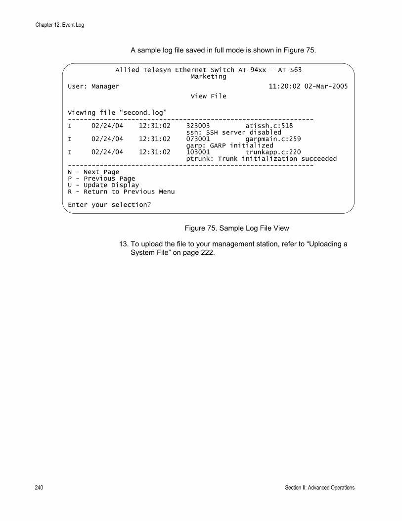
Chapter 12: Event Log
A sample log file saved in full mode is shown in Figure 75.
Figure 75. Sample Log File View
13. To upload the file to your management station, refer to “Uploading a System File” on page 222.
Allied Telesyn Ethernet Switch AT-94xx - AT-S63Marketing
User: Manager 11:20:02 02-Mar-2005
View File
Viewing file “second.log”--------------------------------------------------------------I 02/24/04 12:31:02 323003 atissh.c:518
ssh: SSH server disabledI 02/24/04 12:31:02 073001 garpmain.c:259
garp: GARP initializedI 02/24/04 12:31:02 103001 trunkapp.c:220
ptrunk: Trunk initialization succeeded--------------------------------------------------------------N - Next PageP - Previous PageU - Update DisplayR - Return to Previous Menu
Enter your selection?
240 Section II: Advanced Operations
AT-S63 Management Software Menus Interface User’s Guide
Configuring Log Outputs
As explained in “Event Log Overview” on page 228, there are two methods you can use to view the events generated by the switch. One method is to view one of the switch’s event logs. The drawback to this method is that you must establish a management session with the switch before you can view the logs and you can view the log of only one switch at a time.
The other way to view events is to configure the switch to send its events to a syslog server. A syslog server can store the events of many network devices simultaneously. Therefore, network management is easier because you can go to one location to see all the events.
Observe the following guidelines when you use this feature:
You can define up to 19 log output definitions.The event log on the switch must be enabled in order for the switch to send events. For instructions, refer to “Enabling or Disabling the Event Logs” on page 230.The switch must have an IP address and subnet mask. This rule applies to slave switches, which typically do not have an IP address, as well as to master switches. If you want a slave switch to send its events to a syslog server, you must assign it an IP address and a subnet mask.The syslog server must communicate with the switch through the switch’s management VLAN. The AT-S63 management software uses the management VLAN to watch for and transmit management packets. The default management VLAN is Default_VLAN.
Configuring the switch to send its events to a syslog server involves creating a log output definition. The log output contains the IP address of the syslog server along with other information such as what types of messages you want the switch to send.
This section contains the following procedures:
“Creating a Log Output Definition,” next“Modifying a Log Output” on page 247“Deleting a Log Output” on page 248“Displaying the Log Output Definition Details” on page 249
Creating a LogOutput Definition
To create a log output definition, perform the following procedure:
1. From the Main Menu, type 5 to select System Administration.
The System Administration menu is shown in Figure 4 on page 46.
Section II: Advanced Operations 241
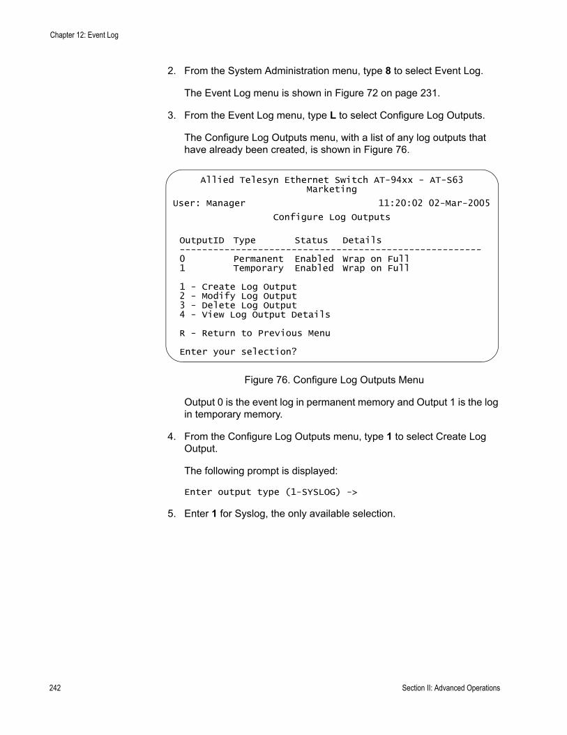
Chapter 12: Event Log
2. From the System Administration menu, type 8 to select Event Log.
The Event Log menu is shown in Figure 72 on page 231.
3. From the Event Log menu, type L to select Configure Log Outputs.
The Configure Log Outputs menu, with a list of any log outputs that have already been created, is shown in Figure 76.
Figure 76. Configure Log Outputs Menu
Output 0 is the event log in permanent memory and Output 1 is the log in temporary memory.
4. From the Configure Log Outputs menu, type 1 to select Create Log Output.
The following prompt is displayed:
Enter output type (1-SYSLOG) ->
5. Enter 1 for Syslog, the only available selection.
Allied Telesyn Ethernet Switch AT-94xx - AT-S63Marketing
User: Manager 11:20:02 02-Mar-2005
Configure Log Outputs
OutputID Type Status Details------------------------------------------------------0 Permanent Enabled Wrap on Full1 Temporary Enabled Wrap on Full
1 - Create Log Output2 - Modify Log Output3 - Delete Log Output4 - View Log Output Details
R - Return to Previous Menu
Enter your selection?
242 Section II: Advanced Operations
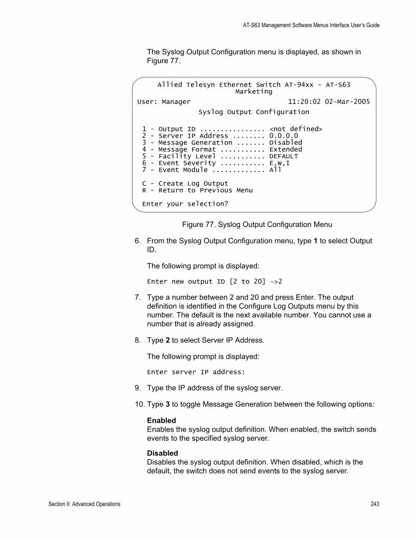
AT-S63 Management Software Menus Interface User’s Guide
The Syslog Output Configuration menu is displayed, as shown in Figure 77.
Figure 77. Syslog Output Configuration Menu
6. From the Syslog Output Configuration menu, type 1 to select Output ID.
The following prompt is displayed:
Enter new output ID [2 to 20] ->2
7. Type a number between 2 and 20 and press Enter. The output definition is identified in the Configure Log Outputs menu by this number. The default is the next available number. You cannot use a number that is already assigned.
8. Type 2 to select Server IP Address.
The following prompt is displayed:
Enter server IP address:
9. Type the IP address of the syslog server.
10. Type 3 to toggle Message Generation between the following options:
EnabledEnables the syslog output definition. When enabled, the switch sends events to the specified syslog server.
DisabledDisables the syslog output definition. When disabled, which is the default, the switch does not send events to the syslog server.
Allied Telesyn Ethernet Switch AT-94xx - AT-S63Marketing
User: Manager 11:20:02 02-Mar-2005
Syslog Output Configuration
1 - Output ID ................ <not defined>2 - Server IP Address ........ 0.0.0.03 - Message Generation ....... Disabled4 - Message Format ........... Extended5 - Facility Level ........... DEFAULT6 - Event Severity ........... E,W,I7 - Event Module ............. All
C - Create Log OutputR - Return to Previous Menu
Enter your selection?
Section II: Advanced Operations 243

Chapter 12: Event Log
11. Type 4 to toggle Message Format between the following options:
NormalSends the severity, module, and description for each event.
ExtendedSends the same information as Normal along with the date, time, and switch’s IP address. This is the default.
12. Type 5 to select Facility Level.
The following prompt is displayed:
Enter Facility level (0-DEFAULT, 1-LOCAL1, 2-LOCAL2, 3-LOCAL3, 4-LOCAL4, 5-LOCAL 5, 6-LOCAL6, 7-LOCAL7) -> [0 to 7] ->
This parameter adds a facility level to the entries when they are sent to the syslog server. The facility level is a way for you to add a numerical code to each entry to help you group entries on the syslog server according to the module of switch that produced them. This grouping helps you determine which event belong to which device when a syslog server is collecting events from several network devices. You can specify only one facility level.
There are two approaches for using this parameter. The first approach is to use the 0-DEFAULT setting which is based on the functional groupings defined in the RFC 3164 standard. The numerical codes that are applicable to the AT-S63 management software and its modules are shown in Table 4.
Table 4. Applicable RFC 3164 Numerical Code and AT-S63 Module Mappings
Numerical Code RFC 3164 Facility AT-S63 Module
4 Security and authorization messages
Security modules:- PSEC- PACCESS- ENCO- PKI- SSH- SSL- MGMTACL- DOS
Authentication modules:- SYSTEM- RADIUS- TACACS+
244 Section II: Advanced Operations
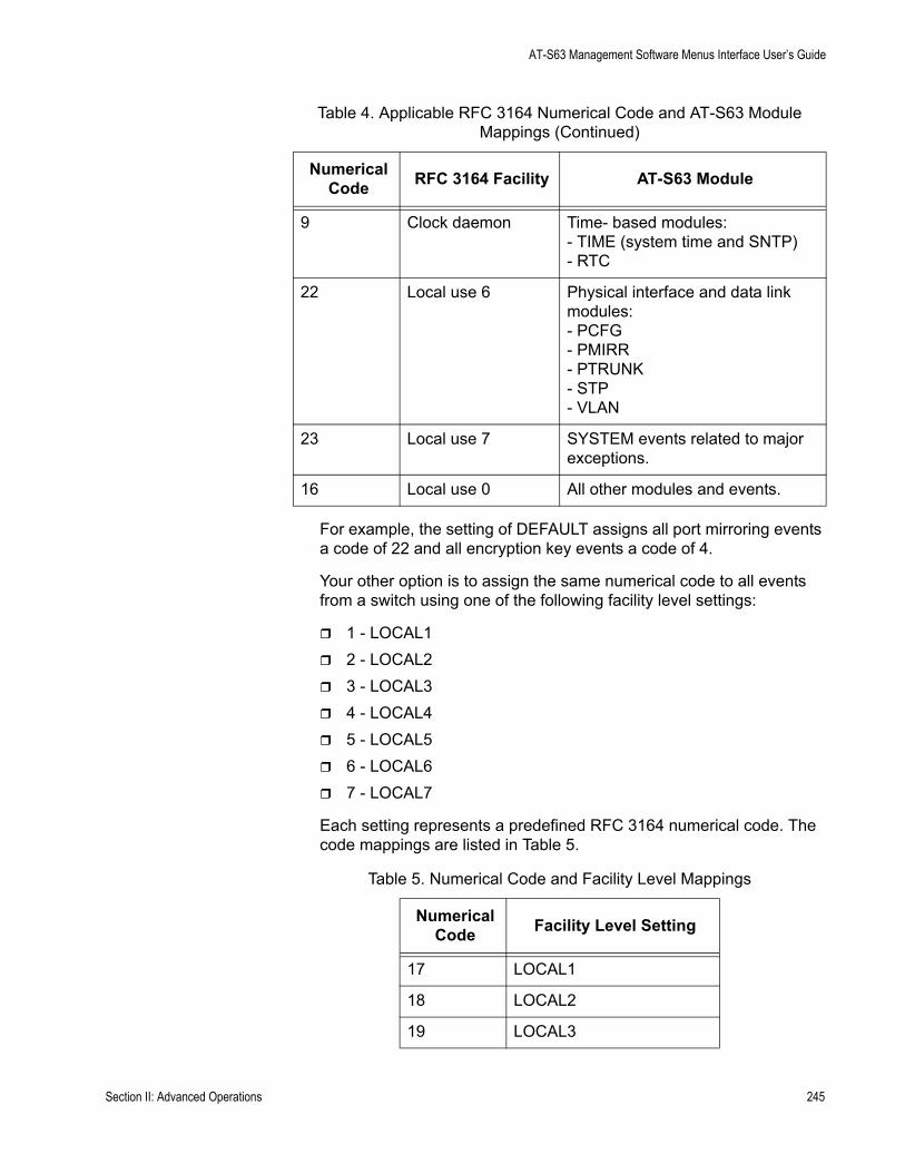
AT-S63 Management Software Menus Interface User’s Guide
For example, the setting of DEFAULT assigns all port mirroring events a code of 22 and all encryption key events a code of 4.
Your other option is to assign the same numerical code to all events from a switch using one of the following facility level settings:
1 - LOCAL12 - LOCAL23 - LOCAL34 - LOCAL45 - LOCAL56 - LOCAL67 - LOCAL7
Each setting represents a predefined RFC 3164 numerical code. The code mappings are listed in Table 5.
9 Clock daemon Time- based modules:- TIME (system time and SNTP)- RTC
22 Local use 6 Physical interface and data link modules:- PCFG- PMIRR- PTRUNK- STP- VLAN
23 Local use 7 SYSTEM events related to major exceptions.
16 Local use 0 All other modules and events.
Table 5. Numerical Code and Facility Level Mappings
Numerical Code Facility Level Setting
17 LOCAL1
18 LOCAL2
19 LOCAL3
Table 4. Applicable RFC 3164 Numerical Code and AT-S63 Module Mappings (Continued)
Numerical Code RFC 3164 Facility AT-S63 Module
Section II: Advanced Operations 245

Chapter 12: Event Log
For example, selecting LOCAL2 as the facility level assigns the numerical code of 18 to all events sent by the switch to the syslog server.
13. To include events of a selected severity, type 6 to select Event Severity.
The following prompt is displayed:
Enter Severity levels to display (ALL, E - Error, W - Warning, I - Information, D - Debug) ->
The possible options are:
ALLAll messages of the following types are displayed. This is the default.
E - ErrorOnly error messages are displayed. Error messages indicate that the switch operation is severely impaired.
W - WarningOnly warning messages are displayed. These messages indicate that an issue may require manager attention.
I - InformationOnly informational messages are displayed. Informational messages display useful information that you can ignore during normal operation.
D - Debug Debug messages provide detailed high-volume information that is intended only for technical support personnel.
You can select more than one severity at a time, separated by a comma, for example, E,W.
14. To send events generated by a particular AT-S63 software module, type 7 to select Event Module.
The list of modules is displayed, as shown in Table 2, “AT-S63 Modules” on page 233. The default is All.
20 LOCAL4
21 LOCAL5
22 LOCAL6
23 LOCAL7
Table 5. Numerical Code and Facility Level Mappings (Continued)
Numerical Code Facility Level Setting
246 Section II: Advanced Operations
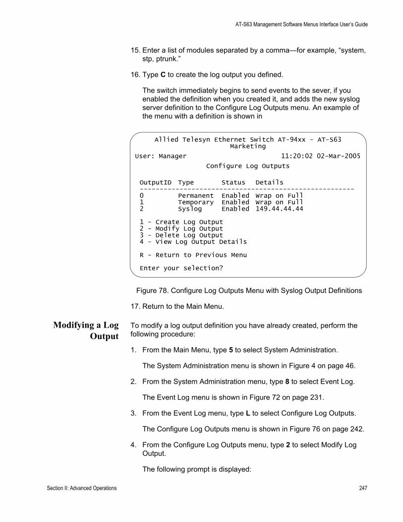
AT-S63 Management Software Menus Interface User’s Guide
15. Enter a list of modules separated by a comma—for example, “system, stp, ptrunk.”
16. Type C to create the log output you defined.
The switch immediately begins to send events to the sever, if you enabled the definition when you created it, and adds the new syslog server definition to the Configure Log Outputs menu. An example of the menu with a definition is shown in
Figure 78. Configure Log Outputs Menu with Syslog Output Definitions
17. Return to the Main Menu.
Modifying a LogOutput
To modify a log output definition you have already created, perform the following procedure:
1. From the Main Menu, type 5 to select System Administration.
The System Administration menu is shown in Figure 4 on page 46.
2. From the System Administration menu, type 8 to select Event Log.
The Event Log menu is shown in Figure 72 on page 231.
3. From the Event Log menu, type L to select Configure Log Outputs.
The Configure Log Outputs menu is shown in Figure 76 on page 242.
4. From the Configure Log Outputs menu, type 2 to select Modify Log Output.
The following prompt is displayed:
Allied Telesyn Ethernet Switch AT-94xx - AT-S63Marketing
User: Manager 11:20:02 02-Mar-2005
Configure Log Outputs
OutputID Type Status Details------------------------------------------------------0 Permanent Enabled Wrap on Full1 Temporary Enabled Wrap on Full2 Syslog Enabled 149.44.44.44
1 - Create Log Output2 - Modify Log Output3 - Delete Log Output4 - View Log Output Details
R - Return to Previous Menu
Enter your selection?
Section II: Advanced Operations 247
Chapter 12: Event Log
Enter output ID to modify [0 to 20] ->
5. Enter the number of the log output that you want to modify.
The Syslog Output Configuration menu is displayed, as shown in Figure 77 on page 243.
6. Refer to “Creating a Log Output Definition” on page 241 for information about the output selections.
7. When you complete the modifications, type M to select Modify Log Output.
The Configure Log Outputs menu as shown in Figure 76 on page 242 is redisplayed.
8. Return to the Main Menu.
Deleting a LogOutput
To delete a log output definition you have already created, perform the following procedure:
1. From the Main Menu, type 5 to select System Administration.
The System Administration menu is shown in Figure 4 on page 46.
2. From the System Administration menu, type 8 to select Event Log.
The Event Log menu is shown in Figure 72 on page 231.
3. From the Event Log menu, type L to select Configure Log Outputs.
The Configure Log Outputs menu is shown in Figure 76 on page 242.
4. From the Configure Log Outputs menu, type 3 to select Modify Log Output.
The following prompt is displayed:
Enter output ID to delete [0 to 20] ->
5. Enter the number of the log output that you want to delete.
The following prompt is displayed:
Are you sure you want to delete output ID x? [Yes/No] ->
6. Enter Y for Yes or N for No and press Enter.
If you enter Y, the output ID you selected is deleted.
7. Return to the Main Menu.
248 Section II: Advanced Operations

AT-S63 Management Software Menus Interface User’s Guide
Displaying theLog Output
Definition Details
To view the settings of a log output definition you have already created, perform the following procedure:
1. From the Main Menu, type 5 to select System Administration.
The System Administration menu is shown in Figure 4 on page 46.
2. From the System Administration menu, type 8 to select Event Log.
The Event Log menu is shown in Figure 72 on page 231.
3. From the Event Log menu, type L to select Configure Log Outputs.
The Configure Log Outputs menu is shown in Figure 76 on page 242.
4. From the Configure Log Outputs menu, type 4 to select View Log Output Details.
The following prompt is displayed:
Enter output ID to view [0 to 20] ->
5. Enter the number of the log output that you want to view.
The Syslog Output Configuration menu for the selected output is displayed, as shown in Figure 79.
Figure 79. Syslog Output Configuration Menu for Selected Output ID
To modify the log output configuration, refer to “Modifying a Log Output” on page 247.
6. Return to the Main Menu.
Allied Telesyn Ethernet Switch AT-94xx - AT-S63Marketing
User: Manager 11:20:02 02-Mar-2005
Syslog Output Configuration
1 - Output ID ................ 32 - Server IP Address ........ 149.35.87.453 - Message Generation ....... Enabled4 - Message Format ........... Extended5 - Facility Level ........... DEFAULT6 - Event Severity ........... E,W,I7 - Event Module ............. All
R - Return to Previous Menu
Enter your selection?
Section II: Advanced Operations 249

Chapter 12: Event Log
250 Section II: Advanced Operations
Chapter 13
Classifiers
This chapter explains classifiers and how you can create classifiers to define traffic flows. The sections in this chapter include:
“Classifier Overview” on page 252“Creating a Classifier” on page 259“Modifying a Classifier” on page 263“Deleting a Classifier” on page 265“Displaying Classifiers” on page 266
Section II: Advanced Operations 251

Chapter 13: Classifiers
Classifier Overview
A classifier defines a traffic flow. A traffic flow consists of packets that share one or more characteristics. A traffic flow can range from being very broad to very specific. An example of the former might be all IP traffic while an example of the latter could be packets with specific source and destination MAC addresses.
A classifier contains a set of criteria you configure to match the traffic flow you want the classifier to define. Examples of the variables include source and destination MAC addresses, source and destination IP addresses, IP protocols, source and destination TCP and UDP ports numbers, and so on. You can also specify more than one criteria within a classifier to make the definition of the traffic flow more specific. Some of the variables you can mix-and-match, but there are restrictions, as explained later in this section in the descriptions of the individual variables.
By itself, a classifier does not perform any action or produce any result because it lacks instructions on what a port should do when it receives a packet that belongs to the defined traffic flow. Rather, the action is established outside the classifier. As a result, you will never use a classifier by itself.
One of the AT-S63 features that uses a classifier is an access control list (ACL), explained in Chapter 14, “Access Control Lists” on page 269. An ACL filters ingress packets on a port by controlling which packets a port will accept and reject. You can use this feature to improve the security of your network or enhance network performance by creating network paths or links dedicated to carrying specific types of traffic.
When you create an ACL you must specify the traffic flow you want the ACL to control. You do that by creating one or more classifiers and adding the classifiers to the ACL. The action that the port takes when an ingress packet matches the traffic flow specified by a classifier is contained in the ACL itself. The action will be to either accept packets of the traffic flow or discard them.
The other feature that uses classifiers is Quality of Service (QoS) policies. You can use this feature to regulate the various traffic flows that pass through the switch. For instance, you might raise or lower their user priority values or increase or decrease their allotted bandwidths.
As with an ACL, you specify the traffic flow of interest by creating one or more classifiers and applying them to a QoS policy. The action to be taken by a port when it receives a packet that corresponds to the prescribed flow is dictated by the QoS policy, as explained in Chapter 16, “Quality of Service” on page 297.
In summary, a classifier is a list of variables that define a traffic flow. You
252 Section II: Advanced Operations

AT-S63 Management Software Menus Interface User’s Guide
apply a classifier to an ACL or a QoS policy to define the traffic flow you want the ACL or QoS policy to affect or control.
ClassifierCriteria
The components of a classifier are defined in the following subsections.
Destination MAC Address (Layer 2)Source MAC Address (Layer 2)
You can identify a traffic flow by specifying the source and/or destination MAC address. For instance, you might create a classifier for a traffic flow destined to a particular destination node, or from a specific source node to a specific destination node, all identified by their MAC addresses.
The management software does not support a classifier based on a range of MAC addresses. Each source and destination MAC address must be considered as a separate traffic flow, requiring its own classifier.
Ethernet 802.2 and Ethernet II Frame Types (Layer 2)
You can create a classifier that filters packets based on Ethernet frame type and whether a packet is tagged or untagged within a frame type. (A tagged Ethernet frame contains within it a field that specifies the ID number of the VLAN to which the frame belongs. Untagged packets lack this field.) Options are:
Ethernet II tagged packetsEthernet II untagged packetsEthernet 802.2 tagged packetsEthernet 802.2 untagged packets
802.1p Priority Level (Layer 2)
A tagged Ethernet frame, as explained in “Tagged VLAN Overview” on page 556, contains within it a field that specifies its VLAN membership. Such frames also contain a user priority level used by the switch to determine the Quality of Service to apply to the frame and which egress queue on the egress port a packet should be stored in. The three bit binary number represents eight priority levels, 0 to 7, with 0 the lowest priority and 7 the highest. Figure 80 illustrates the location of the user priority field
Section II: Advanced Operations 253
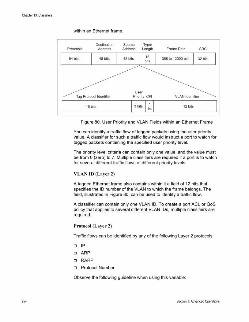
Chapter 13: Classifiers
within an Ethernet frame.
Figure 80. User Priority and VLAN Fields within an Ethernet Frame
You can identify a traffic flow of tagged packets using the user priority value. A classifier for such a traffic flow would instruct a port to watch for tagged packets containing the specified user priority level.
The priority level criteria can contain only one value, and the value must be from 0 (zero) to 7. Multiple classifiers are required if a port is to watch for several different traffic flows of different priority levels.
VLAN ID (Layer 2)
A tagged Ethernet frame also contains within it a field of 12 bits that specifies the ID number of the VLAN to which the frame belongs. The field, illustrated in Figure 80, can be used to identify a traffic flow.
A classifier can contain only one VLAN ID. To create a port ACL or QoS policy that applies to several different VLAN IDs, multiple classifiers are required.
Protocol (Layer 2)
Traffic flows can be identified by any of the following Layer 2 protocols:
IPARPRARPProtocol Number
Observe the following guideline when using this variable:
PreambleDestination
AddressSourceAddress
Type/Length Frame Data CRC
64 bits 48 bits 48 bits 16bits
368 to 12000 bits 32 bits
Tag Protocol IdentifierUser
Priority CFI VLAN Identifier
16 bits 3 bits 1bit 12 bits
254 Section II: Advanced Operations
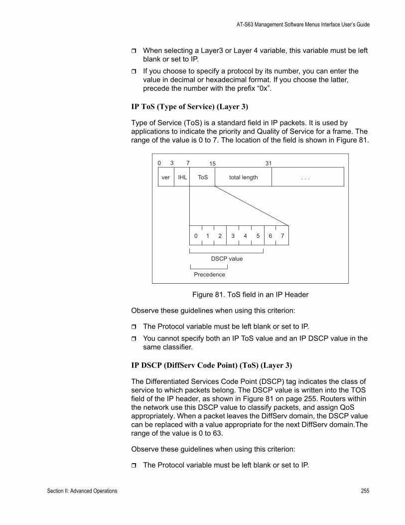
AT-S63 Management Software Menus Interface User’s Guide
When selecting a Layer3 or Layer 4 variable, this variable must be left blank or set to IP.If you choose to specify a protocol by its number, you can enter the value in decimal or hexadecimal format. If you choose the latter, precede the number with the prefix “0x”.
IP ToS (Type of Service) (Layer 3)
Type of Service (ToS) is a standard field in IP packets. It is used by applications to indicate the priority and Quality of Service for a frame. The range of the value is 0 to 7. The location of the field is shown in Figure 81.
Figure 81. ToS field in an IP Header
Observe these guidelines when using this criterion:
The Protocol variable must be left blank or set to IP. You cannot specify both an IP ToS value and an IP DSCP value in the same classifier.
IP DSCP (DiffServ Code Point) (ToS) (Layer 3)
The Differentiated Services Code Point (DSCP) tag indicates the class of service to which packets belong. The DSCP value is written into the TOS field of the IP header, as shown in Figure 81 on page 255. Routers within the network use this DSCP value to classify packets, and assign QoS appropriately. When a packet leaves the DiffServ domain, the DSCP value can be replaced with a value appropriate for the next DiffServ domain.The range of the value is 0 to 63.
Observe these guidelines when using this criterion:
The Protocol variable must be left blank or set to IP.
0
ver IHL
0
3 7
ToS total length
15 31
. . .
1 2 3 4 5 6 7
DSCP value
Precedence
Section II: Advanced Operations 255
Chapter 13: Classifiers
You cannot specify both an IP ToS value and an IP DSCP value in the same classifier.
IP Protocol (Layer 3)
You can define a traffic flow by the following Layer 3 protocols:
TCPUDPICMPIGMPIP protocol number
If you choose to specify a Layer 3 protocol by its number, you can enter the value in decimal or hexadecimal format. It you choose the latter, precede the number with the prefix “0x”.
Source IP Addresses (Layer 3)Source IP Mask (Layer 3)
You can define a traffic flow by the source IP address contained in IP packets. The address can be of a subnet or a specific end node.
You do not need to enter a source IP mask if you are filtering on the IP address of a specific end node. A mask is required, however, when you filter on a subnet. A binary “1” indicates the switch should filter on the corresponding bit of the IP address, while a “0” indicates that it should not. For example, the Class C subnet address 149.11.11.0/24 would have the mask “255.255.255.0.”
Observe this guideline when using these criteria:
The Protocol variable must be left blank or set to IP.
Destination IP Addresses (Layer 3)Destination IP Mask (Layer 3)
You can also define a traffic flow based on the destination IP address of a subnet or a specific end node.
You do not need to enter a destination IP mask if you are filtering on the IP address of a specific end node. A mask is required, however, when filtering on a subnet. Identical to the source IP mask, a binary “1” indicates the switch should filter on the corresponding bit of the IP address, while a “0” indicates that it should not. For example, the Class C subnet address 149.11.11.0/24 would have the mask “255.255.255.0.”
Observe this guideline when using these criteria:
256 Section II: Advanced Operations
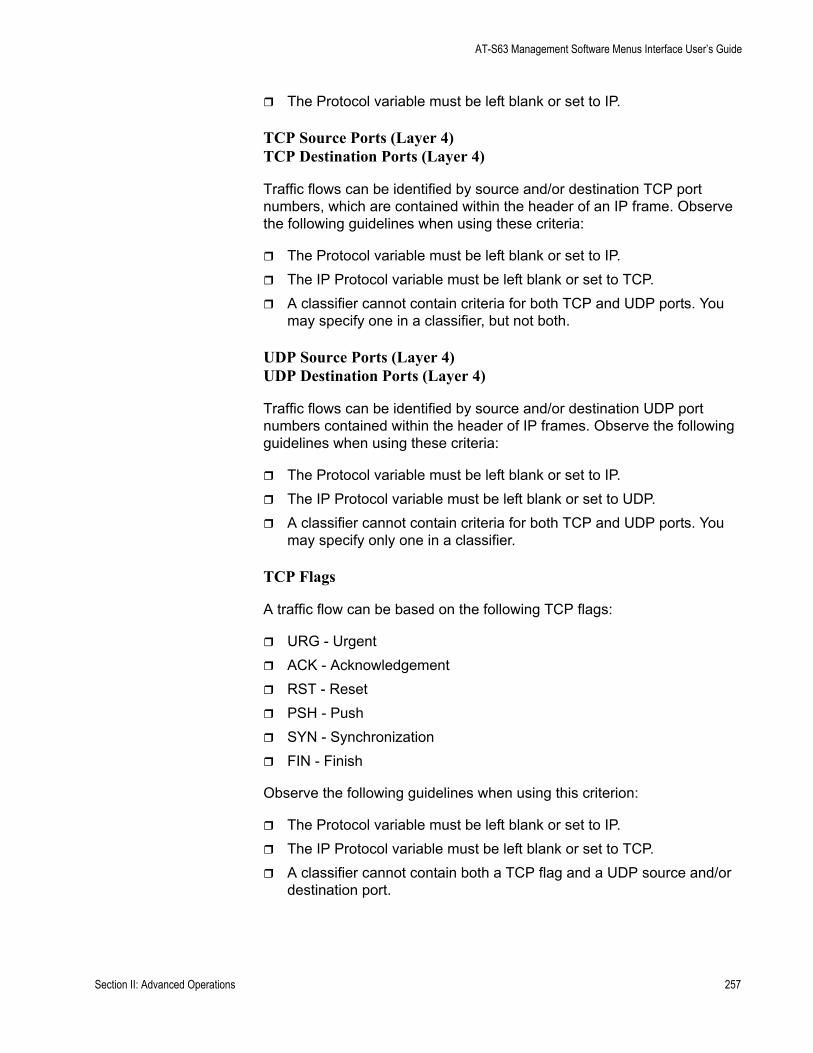
AT-S63 Management Software Menus Interface User’s Guide
The Protocol variable must be left blank or set to IP.
TCP Source Ports (Layer 4)TCP Destination Ports (Layer 4)
Traffic flows can be identified by source and/or destination TCP port numbers, which are contained within the header of an IP frame. Observe the following guidelines when using these criteria:
The Protocol variable must be left blank or set to IP. The IP Protocol variable must be left blank or set to TCP. A classifier cannot contain criteria for both TCP and UDP ports. You may specify one in a classifier, but not both.
UDP Source Ports (Layer 4)UDP Destination Ports (Layer 4)
Traffic flows can be identified by source and/or destination UDP port numbers contained within the header of IP frames. Observe the following guidelines when using these criteria:
The Protocol variable must be left blank or set to IP.The IP Protocol variable must be left blank or set to UDP.A classifier cannot contain criteria for both TCP and UDP ports. You may specify only one in a classifier.
TCP Flags
A traffic flow can be based on the following TCP flags:
URG - UrgentACK - AcknowledgementRST - ResetPSH - PushSYN - SynchronizationFIN - Finish
Observe the following guidelines when using this criterion:
The Protocol variable must be left blank or set to IP.The IP Protocol variable must be left blank or set to TCP.A classifier cannot contain both a TCP flag and a UDP source and/or destination port.
Section II: Advanced Operations 257
Chapter 13: Classifiers
ClassifierGuidelines
Follow these guidelines when creating a classifier:
Each classifier represents a separate traffic flow.The variables within a classifier are linked by AND. The more variables specified within a classifier, the more specific it becomes in terms of the flow you are defining. For instance, specifying both a source IP address and a TCP destination port within the same classifier defines a traffic flow that relates to IP packets containing both the designated source IP address and TCP destination port. However, there are some restrictions to which variables can be used together in the same classifier. For the restrictions, refer to “Classifier Criteria” on page 253.The same classifier can be used for both an ACL and a QoS policy.You can apply the same classifier to more than one ACL or QoS policy.A classifier without any defined variables filters all packets.You cannot create two classifiers that have the same settings. There can be only one classifier for any given type of traffic flow.The switch can store up to 256 classifiers.You cannot modify a classifier if it belongs to an ACL or QoS policy that has already been assigned to a port. You must first remove the port assignments from the ACL or policy and reassign them after you have modified the classifier.
258 Section II: Advanced Operations

AT-S63 Management Software Menus Interface User’s Guide
Creating a Classifier
This section contains the procedure for creating a classifier. As explained in “Classifier Overview” on page 252, a classifier contains a series of variables for defining a traffic flow. This same procedure is used whether the classifier is intended for an ACL or a QoS policy.
To create a classifier, perform the following procedure
1. From the Main Menu, type 7 to select Security and Services.
The Security and Services menu is shown in Figure 82.
Figure 82. Security and Services Menu
2. From the Security and Services menu, type 1 to select Classifier Configuration.
Allied Telesyn Ethernet Switch AT-94xx - AT-S63Marketing
User: Manager 11:20:02 02-Mar-2005
Security and Services
1 - Classifier Configuration2 - Port Access Control (802.1x)3 - Denial of Service (DoS)4 - Access Control Lists (ACL)5 - Class of Service (CoS)6 - Quality of Service (QoS)7 - Keys/Certificates Configuration8 - Secure Shell (SSH)9 - Secure Socket Layer (SSL)
R - Return to Previous Menu
Enter your selection?
Section II: Advanced Operations 259
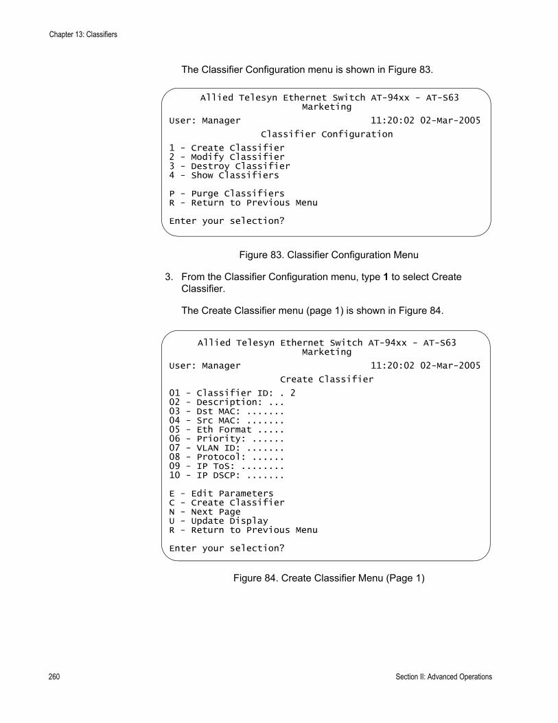
Chapter 13: Classifiers
The Classifier Configuration menu is shown in Figure 83.
Figure 83. Classifier Configuration Menu
3. From the Classifier Configuration menu, type 1 to select Create Classifier.
The Create Classifier menu (page 1) is shown in Figure 84.
Figure 84. Create Classifier Menu (Page 1)
Allied Telesyn Ethernet Switch AT-94xx - AT-S63Marketing
User: Manager 11:20:02 02-Mar-2005
Classifier Configuration
1 - Create Classifier2 - Modify Classifier3 - Destroy Classifier4 - Show Classifiers
P - Purge ClassifiersR - Return to Previous Menu
Enter your selection?
Allied Telesyn Ethernet Switch AT-94xx - AT-S63Marketing
User: Manager 11:20:02 02-Mar-2005
Create Classifier
01 - Classifier ID: . 202 - Description: ...03 - Dst MAC: .......04 - Src MAC: .......05 - Eth Format .....06 - Priority: ......07 - VLAN ID: .......08 - Protocol: ......09 - IP ToS: ........10 - IP DSCP: .......
E - Edit ParametersC - Create ClassifierN - Next PageU - Update DisplayR - Return to Previous Menu
Enter your selection?
260 Section II: Advanced Operations
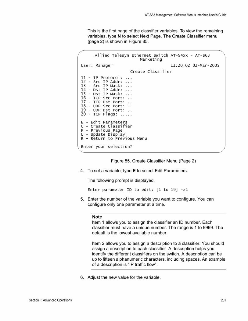
AT-S63 Management Software Menus Interface User’s Guide
This is the first page of the classifier variables. To view the remaining variables, type N to select Next Page. The Create Classifier menu (page 2) is shown in Figure 85.
Figure 85. Create Classifier Menu (Page 2)
4. To set a variable, type E to select Edit Parameters.
The following prompt is displayed.
Enter parameter ID to edit: [1 to 19] ->1
5. Enter the number of the variable you want to configure. You can configure only one parameter at a time.
NoteItem 1 allows you to assign the classifier an ID number. Each classifier must have a unique number. The range is 1 to 9999. The default is the lowest available number.
Item 2 allows you to assign a description to a classifier. You should assign a description to each classifier. A description helps you identify the different classifiers on the switch. A description can be up to fifteen alphanumeric characters, including spaces. An example of a description is “IP traffic flow”.
6. Adjust the new value for the variable.
Allied Telesyn Ethernet Switch AT-94xx - AT-S63Marketing
User: Manager 11:20:02 02-Mar-2005
Create Classifier
11 - IP Protocol: ...12 - Src IP Addr: ...13 - Src IP Mask: ...14 - Dst IP Addr: ...15 - Dst IP Mask: ...16 - TCP Src Port: ..17 - TCP Dst Port: ..18 - UDP Src Port: ..19 - UDP Dst Port: ..20 - TCP Flags: .....
E - Edit ParametersC - Create ClassifierP - Previous PageU - Update DisplayR - Return to Previous Menu
Enter your selection?
Section II: Advanced Operations 261

Chapter 13: Classifiers
Refer to “Classifier Overview” on page 252 for definitions of the variables.
7. Repeat steps 5 and 6 to adjust any other variables necessary to define the traffic flow for this classifier.
8. After configuring the necessary variables, type C to select Create Classifier.
The switch creates the classifier. If any of the settings are incompatible, the system displays an error message. Refer to the variable definitions in “Classifier Criteria” on page 253 for assistance in resolving compatibility issues.
9. To create more classifiers, repeat this procedure starting with step 3.
10. After making changes, type R until you return to the Main Menu. Then type S to select Save Configuration Changes.
11. To add classifiers to an ACL, refer to “Creating an ACL” on page 277. To add classifiers to a QoS policy, refer to “Managing Flow Groups” on page 313.
262 Section II: Advanced Operations

AT-S63 Management Software Menus Interface User’s Guide
Modifying a Classifier
In order to modify a classifier, you need to know its ID number. If you are unsure of the ID number of the classifier you want to modify, refer to “Displaying Classifiers” on page 266.
You cannot modify a classifier if it belongs to an ACL or QoS policy that has already been assigned to a port. You must first remove the port assignments from the ACL or policy before you can modify the classifier.
To modify a classifier, perform the following procedure:
1. From the Main Menu, type 7 to select Security and Services.
The Security and Services menu is shown in Figure 82 on page 259.
2. From the Security and Services menu, type 1 to select Classifier Configuration.
The Classifier Configuration menu is shown in Figure 83 on page 260.
3. From the Classifier Configuration menu, type 2 to select Modify Classifier.
The prompt similar to the following is displayed:
Available Classifier(s): 1-12Enter Classifier ID : [1 to 9999] -> 1
4. Enter the ID number of the classifier you want to modify.
The Modify Classifier window is displayed. This window is identical to the Create Classifier menus, shown in Figure 84 on page 260 and Figure 85 on page 261.
5. Edit the variables as needed.
When modifying a classifier, note the following:
You cannot change a classifier’s ID number.To delete a value from a variable so as to leave it blank, select the criterion and then use the backspace key to delete its default value.
6. Once you have adjusted the variables, type M to select Modify Classifier.
A change to a classifier is immediately activated. If any of the settings are incompatible, the system displays an error message. Refer to the variable definitions in “Classifier Criteria” on page 253 for assistance in resolving any compatibility issues.
Section II: Advanced Operations 263

Chapter 13: Classifiers
7. To modify other classifiers, repeat this process starting with step 3.
8. After making changes, type R until you return to the Main Menu. Then type S to select Save Configuration Changes.
9. To add the modified classifier to an ACL, refer to “Creating an ACL” on page 277 or “Modifying an ACL” on page 280. To add it to a QoS policy, refer to “Managing Flow Groups” on page 313.
264 Section II: Advanced Operations
AT-S63 Management Software Menus Interface User’s Guide
Deleting a Classifier
This procedure deletes a classifier from the switch. To delete a classifier, you need to know its ID number. If you are unsure of the ID number of the classifier you want to delete, refer to “Displaying Classifiers” on page 266.
NoteYou cannot delete a classifier if it belongs to an ACL or QoS policy.You must first remove the port assignments from its ACL or policy assignments before you can delete the classifier.
To delete a classifier, perform the following procedure:
1. From the Main Menu, type 7 to select Security and Services.
The Security and Services menu is shown in Figure 82 on page 259.
2. From the Security and Services menu, type 1 to select Classifier Configuration.
The Classifier Configuration menu is shown in Figure 83 on page 260.
3. From the Classifier Configuration menu, type 3 to select Destroy Classifier.
The following prompt is displayed:
Enter Classifier ID : [1 to 9999] -> 1
4. Enter the ID number of the classifier you want to delete.
The details of the specified classifier are displayed. Use this window to verify that you are deleting the correct classifier.
5. If this is the correct classifier, type D to select Destroy Classifier.
The classifier is deleted from the switch.
6. To delete additional classifiers, repeat this procedure starting with step 3.
7. After making changes, type R until you return to the Main Menu. Then type S to select Save Configuration Changes.
Section II: Advanced Operations 265

Chapter 13: Classifiers
Displaying Classifiers
To display the classifiers on a switch, do the following:
1. From the Main Menu, type 7 to select Security and Services.
The Security and Services menu is shown in Figure 82 on page 259.
2. From the Security and Services menu, type 1 to select Classifier Configuration.
The Classifier Configuration menu is shown in Figure 83 on page 260.
3. From the Classifier Configuration menu, type 4 to select Show Classifiers.
An example of the Show Classifiers menu is shown in Figure 86.
Figure 86. Show Classifiers Menu
The Show Classifiers menu displays the current classifiers in a table with the following columns of information:
IDThe classifier’s ID number.
DescriptionThe description of the classifier.
Number of ReferencesThe number of active and inactive ACL and QoS policy assignments
Allied Telesyn Ethernet Switch AT-94xx - AT-S63Marketing
User: Manager 11:20:02 02-Mar-2005
Show Classifiers
Number of classifiers: 5
ID Description Number of Number ofReferences Active Associations
------------------------------------------------------1 IP flow 4 32 Dst149.11.11.0 1 13 TCP flow 1 04 Src149.22.22.49 1 15 ToS 6 2 2
D - Detail Classifier DisplayU - Update DisplayR - Return to Previous Menu
Enter your selection?
266 Section II: Advanced Operations
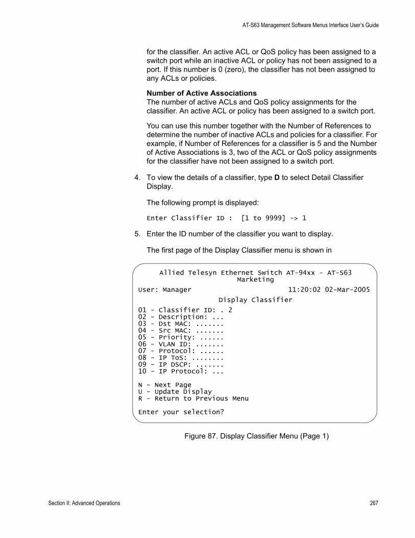
AT-S63 Management Software Menus Interface User’s Guide
for the classifier. An active ACL or QoS policy has been assigned to a switch port while an inactive ACL or policy has not been assigned to a port. If this number is 0 (zero), the classifier has not been assigned to any ACLs or policies.
Number of Active AssociationsThe number of active ACLs and QoS policy assignments for the classifier. An active ACL or policy has been assigned to a switch port.
You can use this number together with the Number of References to determine the number of inactive ACLs and policies for a classifier. For example, if Number of References for a classifier is 5 and the Number of Active Associations is 3, two of the ACL or QoS policy assignments for the classifier have not been assigned to a switch port.
4. To view the details of a classifier, type D to select Detail Classifier Display.
The following prompt is displayed:
Enter Classifier ID : [1 to 9999] -> 1
5. Enter the ID number of the classifier you want to display.
The first page of the Display Classifier menu is shown in
Figure 87. Display Classifier Menu (Page 1)
Allied Telesyn Ethernet Switch AT-94xx - AT-S63Marketing
User: Manager 11:20:02 02-Mar-2005
Display Classifier
01 - Classifier ID: . 202 - Description: ...03 - Dst MAC: .......04 - Src MAC: .......05 - Priority: ......06 - VLAN ID: .......07 - Protocol: ......08 - IP ToS: ........09 - IP DSCP: .......10 - IP Protocol: ...
N - Next PageU - Update DisplayR - Return to Previous Menu
Enter your selection?
Section II: Advanced Operations 267
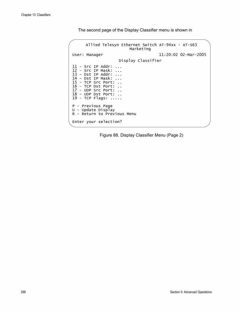
Chapter 13: Classifiers
The second page of the Display Classifier menu is shown in
Figure 88. Display Classifier Menu (Page 2)
Allied Telesyn Ethernet Switch AT-94xx - AT-S63Marketing
User: Manager 11:20:02 02-Mar-2005
Display Classifier
11 - Src IP Addr: ...12 - Src IP Mask: ...13 - Dst IP Addr: ...14 - Dst IP Mask: ...15 - TCP Src Port: ..16 - TCP Dst Port: ..17 - UDP Src Port: ..18 - UDP Dst Port: ..19 - TCP Flags: .....
P - Previous PageU - Update DisplayR - Return to Previous Menu
Enter your selection?
268 Section II: Advanced Operations
Chapter 14
Access Control Lists
This chapter explains access control lists (ACL) and how you can use this feature to improve network security and performance. This chapter contains the following sections:
“Access Control List (ACL) Overview” on page 270“Creating an ACL” on page 277“Modifying an ACL” on page 280“Deleting an ACL” on page 282“Deleting All ACLs” on page 284“Displaying ACLs” on page 285
Section II: Advanced Operations 269
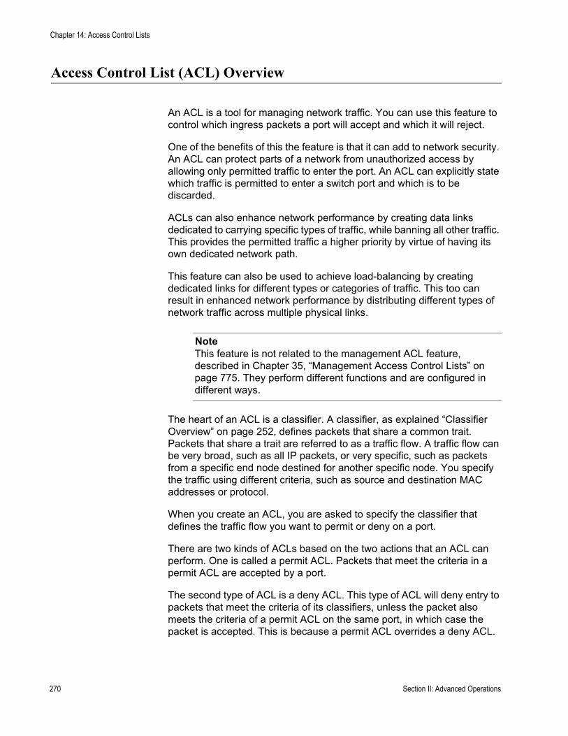
Chapter 14: Access Control Lists
Access Control List (ACL) Overview
An ACL is a tool for managing network traffic. You can use this feature to control which ingress packets a port will accept and which it will reject.
One of the benefits of this the feature is that it can add to network security. An ACL can protect parts of a network from unauthorized access by allowing only permitted traffic to enter the port. An ACL can explicitly state which traffic is permitted to enter a switch port and which is to be discarded.
ACLs can also enhance network performance by creating data links dedicated to carrying specific types of traffic, while banning all other traffic. This provides the permitted traffic a higher priority by virtue of having its own dedicated network path.
This feature can also be used to achieve load-balancing by creating dedicated links for different types or categories of traffic. This too can result in enhanced network performance by distributing different types of network traffic across multiple physical links.
NoteThis feature is not related to the management ACL feature, described in Chapter 35, “Management Access Control Lists” on page 775. They perform different functions and are configured in different ways.
The heart of an ACL is a classifier. A classifier, as explained “Classifier Overview” on page 252, defines packets that share a common trait. Packets that share a trait are referred to as a traffic flow. A traffic flow can be very broad, such as all IP packets, or very specific, such as packets from a specific end node destined for another specific node. You specify the traffic using different criteria, such as source and destination MAC addresses or protocol.
When you create an ACL, you are asked to specify the classifier that defines the traffic flow you want to permit or deny on a port.
There are two kinds of ACLs based on the two actions that an ACL can perform. One is called a permit ACL. Packets that meet the criteria in a permit ACL are accepted by a port.
The second type of ACL is a deny ACL. This type of ACL will deny entry to packets that meet the criteria of its classifiers, unless the packet also meets the criteria of a permit ACL on the same port, in which case the packet is accepted. This is because a permit ACL overrides a deny ACL.
270 Section II: Advanced Operations

AT-S63 Management Software Menus Interface User’s Guide
Here is an overview of how the process works.
1. When an ingress packet arrives on a port, it is checked against the criteria in the classifiers of all the ACLs, both permit and deny, assigned to the port.
2. If the packet matches the criteria of a permit ACL, the port immediately accepts it, even if the packet also matches a deny ACL assigned to the same port, because a permit ACL always overrides a deny ACL.
3. If a packet meets the criteria of a deny ACL but not any permit ACLs on the port, then the packet is discarded.
4. Finally, if a packet does not meet the criteria of any ACLs on a port, it is accepted by the port.
Parts of an ACL To create an ACL, you need to provide the following information:
Name - An ACL needs a name. The name should reflect the type of traffic flow the ACL will be filtering and, perhaps, also the action. An example might be “HTTPS flow - permit.” The more specific the name, the easier it will be for you to identify the different ACLs.Action - An ACL can have one of two actions: permit or deny. An action of permit means that the ingress packets matching the criteria in the classifiers are to be accepted by the switch port. An action of deny means any ingress packets meeting the criteria are to be discarded, provided that the packets do not match any permit ACLs on the port.Classifiers - An ACL needs one or more classifiers to define the traffic flow whose packets you want the port to accept or reject. Each classifier defines a different traffic flow. An ACL can have more than one classifier to filter multiple traffic flows.Port Lists - Finally, you need to specify the ports to which an ACL is to be assigned.
Guidelines Following are rules to observe when it comes to using ACLs:
A port can have multiple permit and deny ACLs.An ACL must have at least one classifier.An ACL can be assigned to more than one switch port.An ACL filters ingress traffic, but not egress traffic.The action of a ACL can be either permit or deny. A permit ACL overrides a deny ACL on the same port.It does not matter the order in which you add ACLs to a port. A packet is compared against all the ACLs assigned to a port.
Section II: Advanced Operations 271

Chapter 14: Access Control Lists
A classifier can be assigned to multiple ACLs. However, a classifier cannot be assigned more than once to a port. Put another way, ACLs that have the same classifier cannot be assigned to the same port.The switch can store up to 64 ACLs.
Examples This section contains several examples of ACLs.
In this example, port 4 has been assigned one ACL, a deny ACL for the subnet 149.11.11.0. This ACL prevents the port from accepting any traffic originating from that subnet. Since this is the only ACL applied to the port, all other traffic is accepted. As explained earlier, a port automatically accepts all packets that do not meet the criteria of the classifiers assigned to its ACLs.
Figure 89. ACL Example 1
Create Access Control Lists (ACL)
1 - ACL ID ................. 42 - Description .......... 149.11.11-deny3 - Action .................. Deny4 - Classifier List ...... 225 - Port List .............. 4
Create Classifier
01 - Classifier ID: ..... 2202 - Description: ...... 149.11.11 flow..12 - Src IP Addr: ..... 149.11.11.013 - Src IP Mask ..... 255.255.255.0
272 Section II: Advanced Operations
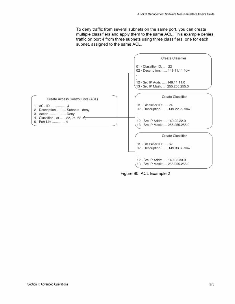
AT-S63 Management Software Menus Interface User’s Guide
To deny traffic from several subnets on the same port, you can create multiple classifiers and apply them to the same ACL. This example denies traffic on port 4 from three subnets using three classifiers, one for each subnet, assigned to the same ACL.
Figure 90. ACL Example 2
Create Access Control Lists (ACL)
1 - ACL ID ................. 42 - Description .......... Subnets - deny3 - Action .................. Deny4 - Classifier List ...... 22, 24, 625 - Port List .............. 4
Create Classifier
01 - Classifier ID: ..... 2402 - Description: ...... 149.22.22 flow..12 - Src IP Addr: ..... 149.22.22.013 - Src IP Mask: .... 255.255.255.0
Create Classifier
01 - Classifier ID: ..... 2202 - Description: ...... 149.11.11 flow..12 - Src IP Addr: ..... 149.11.11.013 - Src IP Mask: .... 255.255.255.0
Create Classifier
01 - Classifier ID: ..... 6202 - Description: ...... 149.33.33 flow..12 - Src IP Addr: ..... 149.33.33.013 - Src IP Mask: .... 255.255.255.0
Section II: Advanced Operations 273
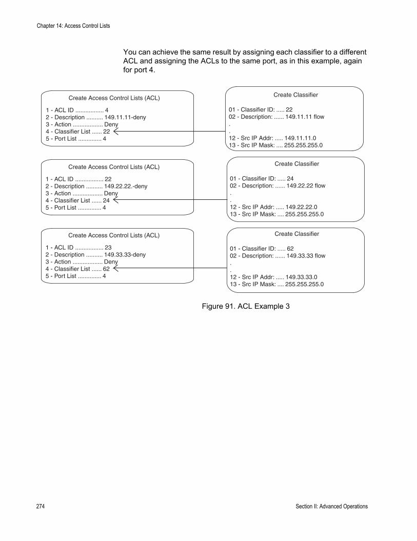
Chapter 14: Access Control Lists
You can achieve the same result by assigning each classifier to a different ACL and assigning the ACLs to the same port, as in this example, again for port 4.
Figure 91. ACL Example 3
Create Access Control Lists (ACL)
1 - ACL ID ................. 222 - Description .......... 149.22.22.-deny3 - Action .................. Deny4 - Classifier List ...... 245 - Port List .............. 4
Create Access Control Lists (ACL)
1 - ACL ID ................. 42 - Description .......... 149.11.11-deny3 - Action .................. Deny4 - Classifier List ...... 225 - Port List .............. 4
Create Access Control Lists (ACL)
1 - ACL ID ................. 232 - Description .......... 149.33.33-deny3 - Action .................. Deny4 - Classifier List ...... 625 - Port List .............. 4
Create Classifier
01 - Classifier ID: ..... 2402 - Description: ...... 149.22.22 flow..12 - Src IP Addr: ..... 149.22.22.013 - Src IP Mask: .... 255.255.255.0
Create Classifier
01 - Classifier ID: ..... 2202 - Description: ...... 149.11.11 flow..12 - Src IP Addr: ..... 149.11.11.013 - Src IP Mask: .... 255.255.255.0
Create Classifier
01 - Classifier ID: ..... 6202 - Description: ...... 149.33.33 flow..12 - Src IP Addr: ..... 149.33.33.013 - Src IP Mask: .... 255.255.255.0
274 Section II: Advanced Operations

AT-S63 Management Software Menus Interface User’s Guide
In this example, the traffic on ports 14 and 15 is restricted to packets from the source subnet 149.44.44.0. All other IP traffic is denied. Classifier ID 11, which specifies the traffic flow to be permitted by the ports, is assigned to an ACL with an action of permit. Classifier ID 17 specifies all IP traffic and is assigned to an ACL whose action is deny. Since a permit ACL overrides a deny ACL, the port will accept the traffic from the 149.44.44.0 subnet even though that traffic also happens to meet the criteria of the deny ACL.
Figure 92. ACL Example 4
This example limits the traffic on port 22 to HTTPS web traffic intended for the end node with the IP address 149.55.55.55, while rejecting all other IP traffic. (The Dst IP Mask field in classifier 6 is left empty because you do not need to specify a mask for the source or destination IP address of an end node. If you want to include a mask, it would be 255.255.255.255.)
Figure 93. ACL Example 5
Create Access Control Lists (ACL)
1 - ACL ID ................. 212 - Description .......... 149.44.44-permit3 - Action .................. Permit4 - Classifier List ...... 115 - Port List .............. 14,15
Create Classifier
01 - Classifier ID: ..... 1102 - Description: ....... 149.44.44-flow..12 - Src IP Addr: ....... 149.44.44.013 - Src IP Mask: ...... 255.255.255.0
Create Access Control Lists (ACL)
1 - ACL ID ................. 52 - Description .......... All IP - deny3 - Action .................. Deny4 - Classifier List ...... 175 - Port List .............. 14,15
Create Classifier
01 - Classifier ID: ..... 1702 - Description: ....... All IP flow..08 - Protocol: ............ IP
Create Access Control Lists (ACL)
1 - ACL ID ................. 42 - Description .......... Web - permit3 - Action .................. Permit4 - Classifier List ...... 65 - Port List .............. 22
Create Classifier
01 - Classifier ID: ...... 602 - Description: ....... 55.55 HTTPS..14 - Dst IP Addr: ....... 149.55.55.5515 - Dst IP Mask: .......17 - TCP Dst Port: ..... 443
Create Access Control Lists (ACL)
1 - ACL ID ................. 52 - Description .......... All IP - deny3 - Action .................. Deny4 - Classifier List ...... 175 - Port List .............. 22
Create Classifier
01 - Classifier ID: ..... 1702 - Description: ....... All IP flow..08 - Protocol: ............ IP
Section II: Advanced Operations 275
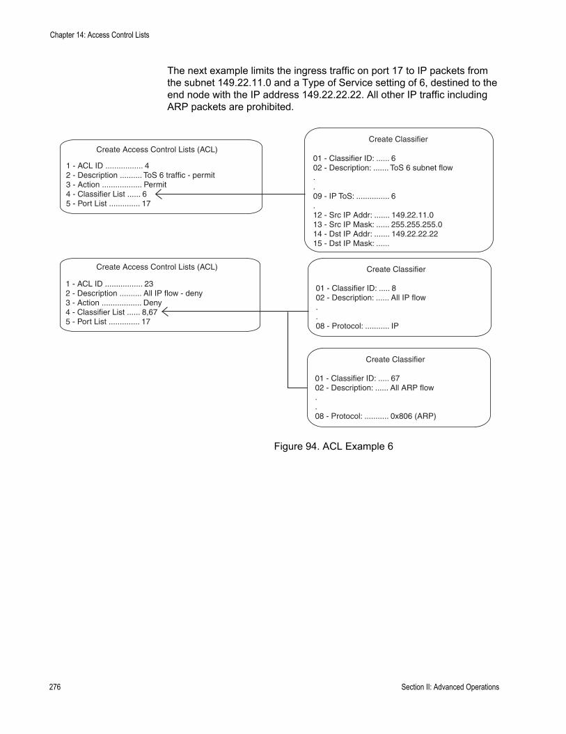
Chapter 14: Access Control Lists
The next example limits the ingress traffic on port 17 to IP packets from the subnet 149.22.11.0 and a Type of Service setting of 6, destined to the end node with the IP address 149.22.22.22. All other IP traffic including ARP packets are prohibited.
Figure 94. ACL Example 6
Create Access Control Lists (ACL)
1 - ACL ID ................. 42 - Description .......... ToS 6 traffic - permit3 - Action .................. Permit4 - Classifier List ...... 65 - Port List .............. 17
Create Classifier
01 - Classifier ID: ...... 602 - Description: ....... ToS 6 subnet flow..09 - IP ToS: ............... 6.12 - Src IP Addr: ....... 149.22.11.013 - Src IP Mask: ...... 255.255.255.014 - Dst IP Addr: ....... 149.22.22.2215 - Dst IP Mask: ......
Create Access Control Lists (ACL)
1 - ACL ID ................. 232 - Description .......... All IP flow - deny3 - Action .................. Deny4 - Classifier List ...... 8,675 - Port List .............. 17
Create Classifier
01 - Classifier ID: ..... 802 - Description: ...... All IP flow..08 - Protocol: ........... IP
Create Classifier
01 - Classifier ID: ..... 6702 - Description: ...... All ARP flow..08 - Protocol: ........... 0x806 (ARP)
276 Section II: Advanced Operations
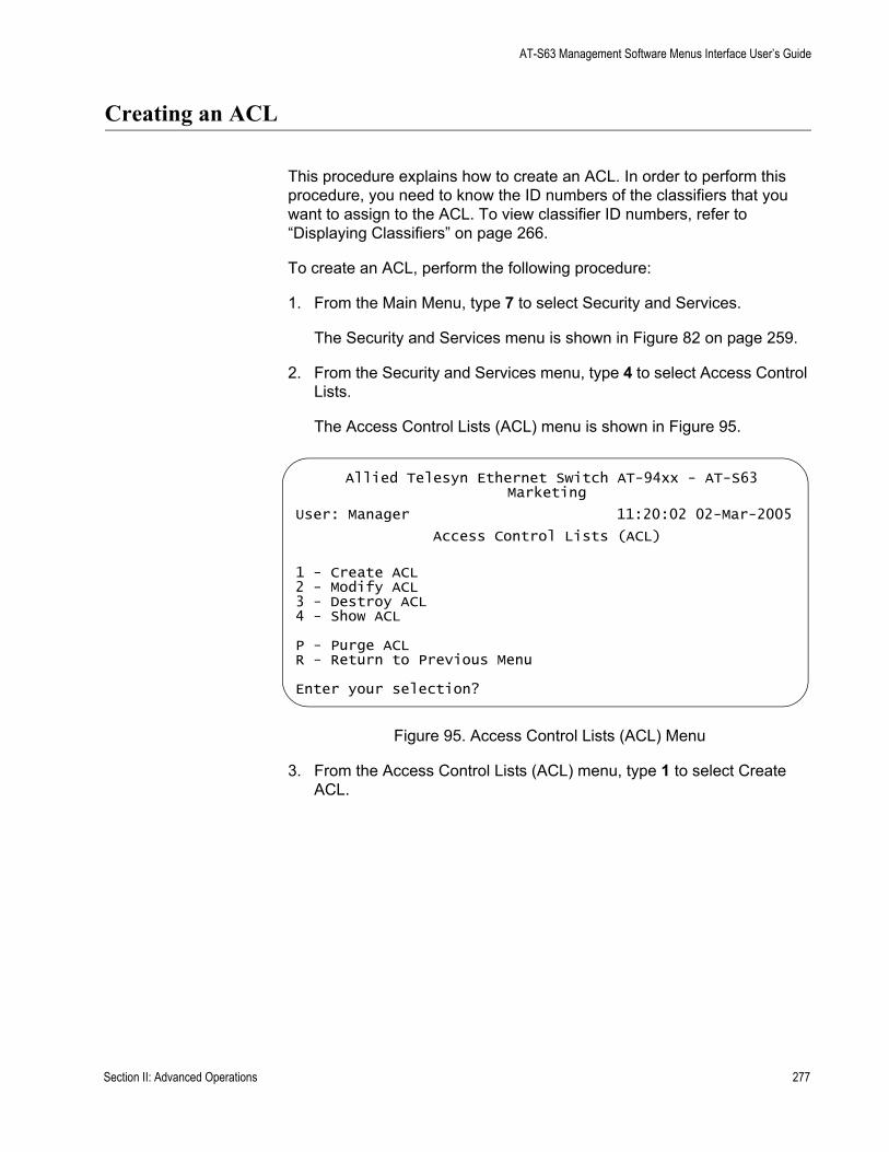
AT-S63 Management Software Menus Interface User’s Guide
Creating an ACL
This procedure explains how to create an ACL. In order to perform this procedure, you need to know the ID numbers of the classifiers that you want to assign to the ACL. To view classifier ID numbers, refer to “Displaying Classifiers” on page 266.
To create an ACL, perform the following procedure:
1. From the Main Menu, type 7 to select Security and Services.
The Security and Services menu is shown in Figure 82 on page 259.
2. From the Security and Services menu, type 4 to select Access Control Lists.
The Access Control Lists (ACL) menu is shown in Figure 95.
Figure 95. Access Control Lists (ACL) Menu
3. From the Access Control Lists (ACL) menu, type 1 to select Create ACL.
Allied Telesyn Ethernet Switch AT-94xx - AT-S63Marketing
User: Manager 11:20:02 02-Mar-2005
Access Control Lists (ACL)
1 - Create ACL2 - Modify ACL3 - Destroy ACL4 - Show ACL
P - Purge ACLR - Return to Previous Menu
Enter your selection?
Section II: Advanced Operations 277
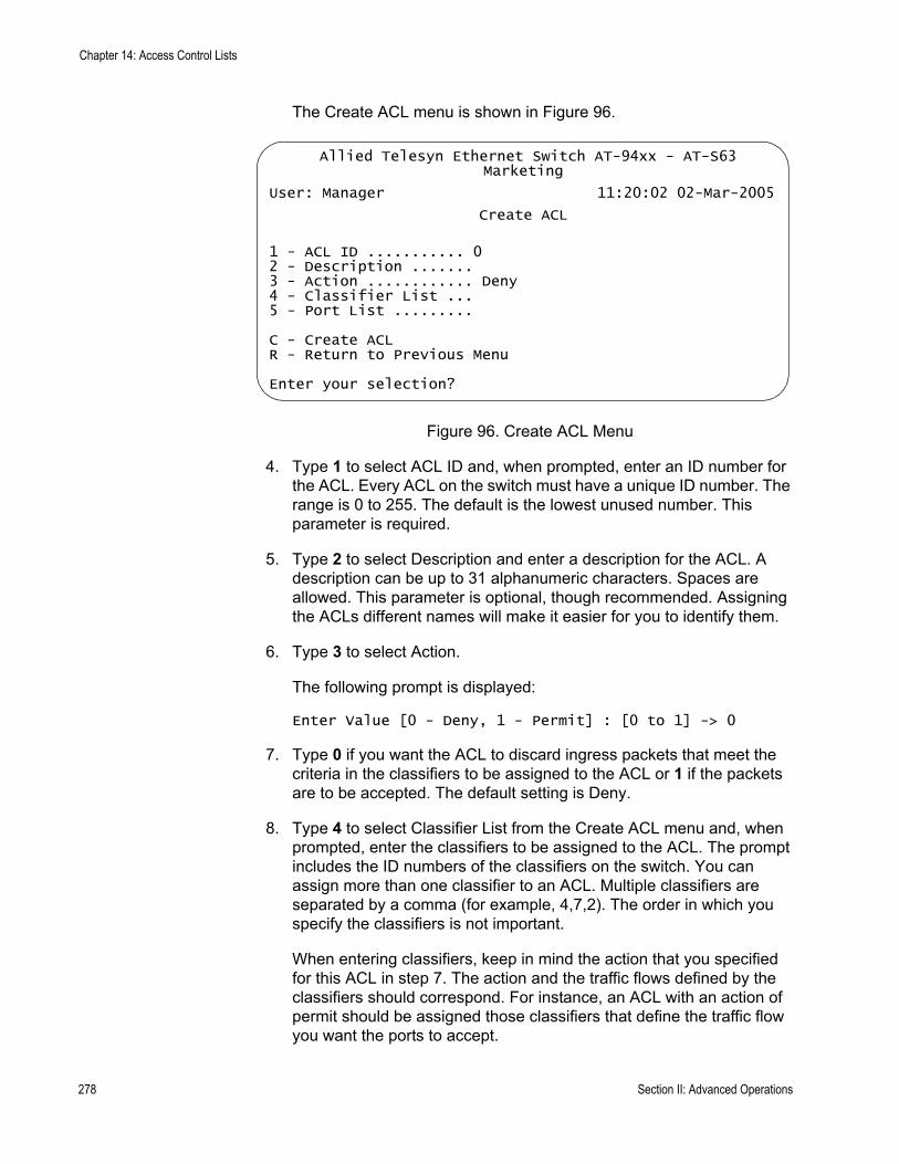
Chapter 14: Access Control Lists
The Create ACL menu is shown in Figure 96.
Figure 96. Create ACL Menu
4. Type 1 to select ACL ID and, when prompted, enter an ID number for the ACL. Every ACL on the switch must have a unique ID number. The range is 0 to 255. The default is the lowest unused number. This parameter is required.
5. Type 2 to select Description and enter a description for the ACL. A description can be up to 31 alphanumeric characters. Spaces are allowed. This parameter is optional, though recommended. Assigning the ACLs different names will make it easier for you to identify them.
6. Type 3 to select Action.
The following prompt is displayed:
Enter Value [0 - Deny, 1 - Permit] : [0 to 1] -> 0
7. Type 0 if you want the ACL to discard ingress packets that meet the criteria in the classifiers to be assigned to the ACL or 1 if the packets are to be accepted. The default setting is Deny.
8. Type 4 to select Classifier List from the Create ACL menu and, when prompted, enter the classifiers to be assigned to the ACL. The prompt includes the ID numbers of the classifiers on the switch. You can assign more than one classifier to an ACL. Multiple classifiers are separated by a comma (for example, 4,7,2). The order in which you specify the classifiers is not important.
When entering classifiers, keep in mind the action that you specified for this ACL in step 7. The action and the traffic flows defined by the classifiers should correspond. For instance, an ACL with an action of permit should be assigned those classifiers that define the traffic flow you want the ports to accept.
Allied Telesyn Ethernet Switch AT-94xx - AT-S63Marketing
User: Manager 11:20:02 02-Mar-2005
Create ACL
1 - ACL ID ........... 02 - Description .......3 - Action ............ Deny4 - Classifier List ...5 - Port List .........
C - Create ACLR - Return to Previous Menu
Enter your selection?
278 Section II: Advanced Operations

AT-S63 Management Software Menus Interface User’s Guide
9. Type 5 to select Port List and, when prompted, enter the ports where you want to assign the ACL. You can assign an ACL to just one port or to more than one port. When entering multiple ports, the ports can be listed individually (e.g., 2,5,7), as a range (e.g., 8-12) or both (e.g., 1-4,6,8).
10. Type C to select Create ACL.
The ACL is created on the switch and immediately activated on the specified ports.
11. To create additional ACLs, repeat this procedure starting with step 3.
12. After making changes, type R until you return to the Main Menu. Then type S to select Save Configuration Changes.
Section II: Advanced Operations 279
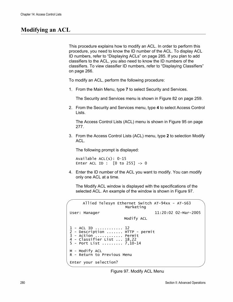
Chapter 14: Access Control Lists
Modifying an ACL
This procedure explains how to modify an ACL. In order to perform this procedure, you need to know the ID number of the ACL. To display ACL ID numbers, refer to “Displaying ACLs” on page 285. If you plan to add classifiers to the ACL, you also need to know the ID numbers of the classifiers. To view classifier ID numbers, refer to “Displaying Classifiers” on page 266.
To modify an ACL, perform the following procedure:
1. From the Main Menu, type 7 to select Security and Services.
The Security and Services menu is shown in Figure 82 on page 259.
2. From the Security and Services menu, type 4 to select Access Control Lists.
The Access Control Lists (ACL) menu is shown in Figure 95 on page 277.
3. From the Access Control Lists (ACL) menu, type 2 to selection Modify ACL.
The following prompt is displayed:
Available ACL(s): 0-15Enter ACL ID : [0 to 255] -> 0
4. Enter the ID number of the ACL you want to modify. You can modify only one ACL at a time.
The Modify ACL window is displayed with the specifications of the selected ACL. An example of the window is shown in Figure 97.
Figure 97. Modify ACL Menu
Allied Telesyn Ethernet Switch AT-94xx - AT-S63Marketing
User: Manager 11:20:02 02-Mar-2005
Modify ACL
1 - ACL ID ............ 122 - Description ....... HTTP - permit3 - Action ............ Permit4 - Classifier List ... 18,225 - Port List ......... 7,10-14
M - Modify ACLR - Return to Previous Menu
Enter your selection?
280 Section II: Advanced Operations
AT-S63 Management Software Menus Interface User’s Guide
You cannot change an ACL’s ID number.
5. To change the description of the ACL, type 2 to select Description and enter a new description for the ACL. The description can be up to 31 alphanumeric characters. Spaces are allowed. This parameter is optional, though recommended. Assigning each ACL a name will make it easier for you to identify them.
6. To change the ACL’s action, type 3 to select Action.
The following prompt is displayed:
Enter Value [0-Deny, 1-Permit] : [0 to 1] -> 0
7. Type 0 if you want the ACL to discard ingress packets that meet the criteria in the classifiers to be assigned to the ACL or 1 if the packets are to be accepted. The default setting is Deny.
8. To change the classifiers assigned to the ACL, type 4 to select Classifier List and, when prompted, enter the classifiers. The prompt includes the ID numbers of the classifiers on the switch. You can assign more than one classifier to an ACL. Multiple classifiers are separated by a comma (for example, 2,4,7). The order in which you specify the classifiers is not important.
When entering classifiers, keep in mind the action you specified for this ACL in step 7. The action and the traffic flows defined by the classifiers should correspond. For instance, an ACL with an action of permit should be assigned those classifiers that define the traffic flow you want ports to accept.
9. To change the ports to which the ACL is assigned, type 5 to select Port List and, when prompted, enter the ports where you want to assign the ACL. You can assign an ACL to more than one port. Ports can be listed individually (e.g., 2,5,7), as a range (e.g., 8-12) or both (e.g., 1-4,6,8).
10. Type M to select Modify ACL.
The ACL is modified on the switch. Modifications take affect immediately.
11. To modify additional ACLs, repeat this procedure starting with step 3.
12. After making changes, type R until you return to the Main Menu. Then type S to select Save Configuration Changes.
Section II: Advanced Operations 281
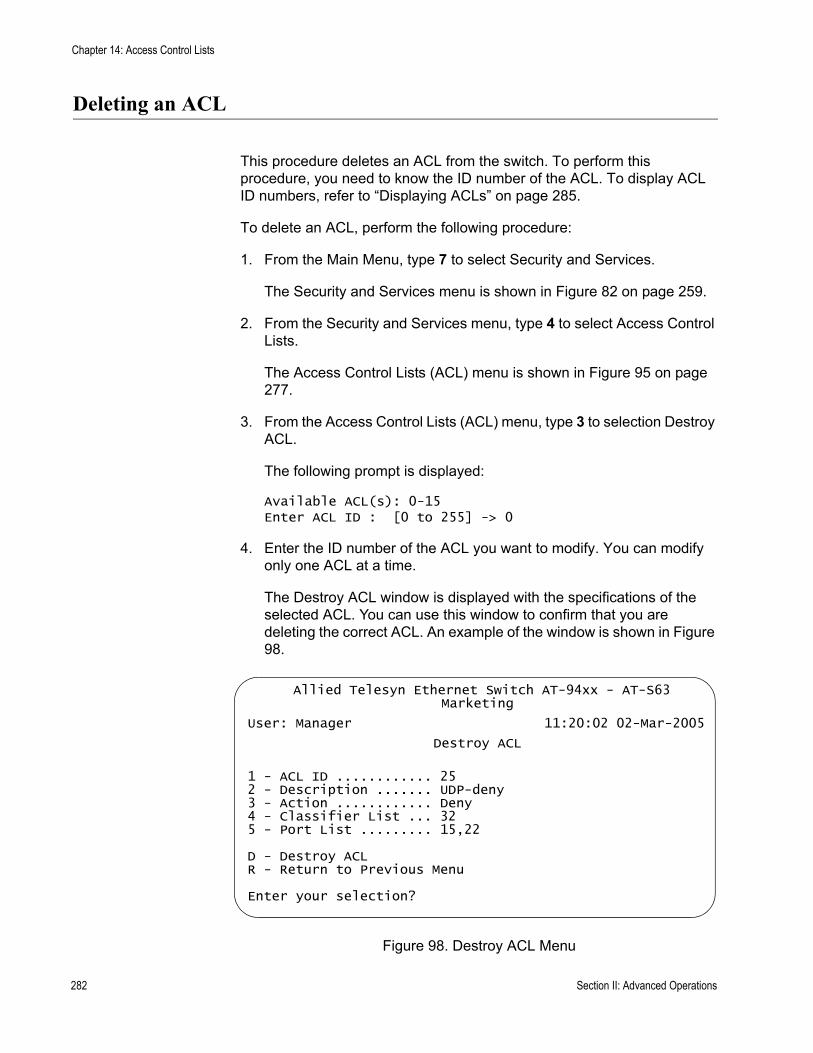
Chapter 14: Access Control Lists
Deleting an ACL
This procedure deletes an ACL from the switch. To perform this procedure, you need to know the ID number of the ACL. To display ACL ID numbers, refer to “Displaying ACLs” on page 285.
To delete an ACL, perform the following procedure:
1. From the Main Menu, type 7 to select Security and Services.
The Security and Services menu is shown in Figure 82 on page 259.
2. From the Security and Services menu, type 4 to select Access Control Lists.
The Access Control Lists (ACL) menu is shown in Figure 95 on page 277.
3. From the Access Control Lists (ACL) menu, type 3 to selection Destroy ACL.
The following prompt is displayed:
Available ACL(s): 0-15Enter ACL ID : [0 to 255] -> 0
4. Enter the ID number of the ACL you want to modify. You can modify only one ACL at a time.
The Destroy ACL window is displayed with the specifications of the selected ACL. You can use this window to confirm that you are deleting the correct ACL. An example of the window is shown in Figure 98.
Figure 98. Destroy ACL Menu
Allied Telesyn Ethernet Switch AT-94xx - AT-S63Marketing
User: Manager 11:20:02 02-Mar-2005
Destroy ACL
1 - ACL ID ............ 252 - Description ....... UDP-deny3 - Action ............ Deny4 - Classifier List ... 325 - Port List ......... 15,22
D - Destroy ACLR - Return to Previous Menu
Enter your selection?
282 Section II: Advanced Operations

AT-S63 Management Software Menus Interface User’s Guide
5. To delete the ACL, type D to select Destroy ACL. To cancel the procedure, type R to select Return to Previous Menu.
A deleted ACL is immediately removed from the switch.
6. To delete additional ACLs, repeat this procedure starting with step 3.
7. After making changes, type R until you return to the Main Menu. Then type S to select Save Configuration Changes.
Section II: Advanced Operations 283

Chapter 14: Access Control Lists
Deleting All ACLs
This procedure deletes all ACLs from the switch.
To delete all ACLs, perform the following procedure:
1. From the Main Menu, type 7 to select Security and Services.
2. From the Security and Services menu, type 4 to select Access Control Lists.
The Access Control Lists (ACL) menu is shown in Figure 95 on page 277.
3. From the Access Control Lists (ACL) menu, type P to selection Purge ACLs.
CautionNo confirmation prompt is displayed. All ACLs are immediately deleted from the switch.
4. After making changes, type R until you return to the Main Menu. Then type S to select Save Configuration Changes.
284 Section II: Advanced Operations
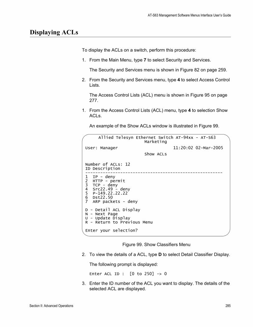
AT-S63 Management Software Menus Interface User’s Guide
Displaying ACLs
To display the ACLs on a switch, perform this procedure:
1. From the Main Menu, type 7 to select Security and Services.
The Security and Services menu is shown in Figure 82 on page 259.
2. From the Security and Services menu, type 4 to select Access Control Lists.
The Access Control Lists (ACL) menu is shown in Figure 95 on page 277.
1. From the Access Control Lists (ACL) menu, type 4 to selection Show ACLs.
An example of the Show ACLs window is illustrated in Figure 99.
Figure 99. Show Classifiers Menu
2. To view the details of a ACL, type D to select Detail Classifier Display.
The following prompt is displayed:
Enter ACL ID : [0 to 250] -> 0
3. Enter the ID number of the ACL you want to display. The details of the selected ACL are displayed.
Allied Telesyn Ethernet Switch AT-94xx - AT-S63Marketing
User: Manager 11:20:02 02-Mar-2005
Show ACLs
Number of ACLs: 12ID Description-------------------------------------------------------1 IP - deny2 HTTP - permit3 TCP - deny4 Src22.49 - deny5 P-149.22.22.226 Dst22.507 ARP packets - deny
D - Detail ACL DisplayN - Next PageU - Update DisplayR - Return to Previous Menu
Enter your selection?
Section II: Advanced Operations 285

Chapter 14: Access Control Lists
286 Section II: Advanced Operations
Chapter 15
Denial of Service Defense
This chapter contains procedures for configuring the switch to protect against denial of service (DoS) attacks. Sections in the chapter include:
“Denial of Service Overview” on page 288“Configuring Denial of Service Defense” on page 293
Section II: Advanced Operations 287
Chapter 15: Denial of Service Defense
Denial of Service Overview
The AT-S63 management software can help protect your switch against the following types of denial of service attacks.
SYN Flood AttackSMURF AttackLand AttackTeardrop AttackPing of Death AttackIP Options Attack
The following subsections briefly describe each type of attack and the mechanism employed by the AT-S63 management software to protect your network.
NoteBe sure to read the following descriptions before you implement a DoS defense on a switch. Some defense mechanisms are CPU intensive and can impact switch behavior.
SYN FloodAttack
In this type of attack, an attacker sends a large number of TCP connection requests (TCP SYN packets) with bogus source addresses to the victim. The victim responds with acknowledgements (SYN ACK packets), but because the original source addresses are bogus, the victim node does not receive any replies. If the attacker sends enough requests in a short enough period, the victim may freeze operations when the number of requests exceeds the capacity of its connections queue.
To defend against this form of attack, a switch port monitors the number of ingress TCP connection requests it receives. If a port receives more than 60 requests per second, the following occurs.
The switch sends an SNMP trap to the management stations The port discards all ingress TCP-SYN packets for one minute. However, the port continues to allow existing TCP connections to go through.
This defense mechanism does not involve the switch’s CPU. You can activate it on as many ports as you want without it impacting switch performance.
SMURF Attack This DoS attack is instigated by an attacker sending a ICMP Echo (Ping) request containing a broadcast address as the destination address and the address of the victim as the source of the ICMP Echo (Ping) request.
288 Section II: Advanced Operations

AT-S63 Management Software Menus Interface User’s Guide
This overwhelms the victim with a large number of ICMP Echo (Ping) replies from the other network nodes.
A switch port defends against this form of attack by examining the destination addresses of ingress ICMP Echo (Ping) request packets and discarding those that contain a broadcast address as a destination address.
Implementing this defense requires that you provide an IP address of a node on your network and a subnet mask. The switch uses the two to determine the broadcast address of your network.
This defense mechanism does not involve the switch’s CPU. You can activate it on as many ports as you want without having it negatively impact switch performance.
Land Attack In this attack, an attacker sends a bogus IP packet where the source and destination IP addresses are the same. This leaves the victim thinking that it is sending a message to itself.
The most direct approach for defending against this form of attack is for the AT-S63 management software to check the source and destination IP addresses in the IP packets, searching for and discarding those with identical source and destination addresses. But this requires too much processing by the switch’s CPU, and would adversely impact switch performance.
Instead, the switch examines the IP packets that are entering or leaving your network. IP packets generated within your network and containing a local IP address as the destination address are not allowed to leave the network, but IP packets generated outside the network but containing a local IP address as the source address are not allowed into the network.
In order for this defense mechanism to work, you need to specify an uplink port. This is the port on the switch that is connected to the device, such as a DSL router, that leads outside your network. You can specify only one uplink port.
The switch uses the uplink port to gauge whether packets generated outside your network should be allowed to enter, and whether packets generated within your network should be allowed to leave.
NoteIf none of the ports on a switch are connected to a device that leads outside your network, you should not use this defense mechanism.
Following is a simplified overview of how the process takes place. This example assumes that you have activated the feature on port 4 and that you have specified port 1 as the uplink port. The steps below review what
Section II: Advanced Operations 289

Chapter 15: Denial of Service Defense
happens when an ingress IP packet arrives on port 4:
1. When port 4 receives an ingress IP packet with a destination MAC address learned on uplink port 1, it examines the packet’s destination IP addresses before forwarding the packet.
2. If the destination IP address is local to the network, port 4 does not forward the packet to uplink port 1 because the port assumes that there is no reason for the packet to leave the network. Instead, it discards the packet.
3. If the destination IP address is not local to the network, port 4 forwards the packet to uplink port 1.
Below is a review of how the process takes place when an ingress IP packet arrives on uplink port 1 that is destined for port 4:
1. Whenever uplink port 1 receives an ingress IP packet with a destination MAC address that was learned on port 4, it examines the packet’s source IP address before forwarding the packet.
2. If the source IP address is local to the network, uplink port 1 does not forward the packet to port 4 because it assumes that a packet with a source IP address that is local to the network should not be entering the network from outside the network.
3. If the source IP address is not local to the network, port 1 forwards the packet to port 4.
Following are some guidelines for using this defense:
If you choose to use it, Allied Telesyn recommends activating it on all ports on the switch, including the uplink port. You can specify only one uplink port.
This form of defense is not CPU intensive. Activating it on all ports should not affect switch behavior.
Teardrop Attack An attacker sends an IP packet in several fragments with a bogus offset value, used to reconstruct the packet, in one of the fragments to a victim. The victim is unable to reassemble the packet, possibly causing it to freeze operations.
The defense mechanism for this type of attack has all ingress IP traffic received on a port sent to the switch’s CPU. The CPU samples related, consecutive fragments, checking for fragments with invalid offset values.
If one is found, the following occurs:
The switch sends an SNMP trap to the management stations.
290 Section II: Advanced Operations
AT-S63 Management Software Menus Interface User’s Guide
The switch port discards the fragment with the invalid offset and, for a one minute period, discards all ingress fragmented IP traffic.
Because the CPU only samples the ingress IP traffic, this defense mechanism may catch some, though not necessarily all, of this form of attack.
CautionThis defense is extremely CPU intensive; use with caution. Unrestricted use can cause a switch to halt operations if the CPU becomes overwhelmed with IP traffic. To prevent this, Allied Telesyn recommends activating this defense on only the uplink port and one other switch port at a time.
Ping of DeathAttack
The attacker sends an oversized, fragmented ICMP Echo (Ping) request (greater than 65,535 bits) to the victim, which, if lacking a policy for handling oversized packets, may freeze.
To defend against this form of attack, a switch port searches for the last fragment of a fragmented ICMP Echo (Ping) request and examines its offset to determine if the packet size is greater than 63,488 bits. If it is, the fragment is forwarded to the switch’s CPU for final packet size determination. If the switch determines that the packet is oversized, the following occurs:
The switch sends an SNMP trap to the management stations.The switch port discards the fragment and, for one minute, discards all fragmented ingress ICMP Echo (Ping) requests.
NoteThis defense mechanism requires some involvement by the switch’s CPU, though not as much as the Teardrop defense. This does not impact the forwarding of traffic between the switch ports, but it can affect the handling of CPU events, such as the processing of IGMP packets and spanning tree BPDUs. For this reason, Allied Telesyn recommends limiting the use of this defense, activating it only on those ports where an attack is most likely to originate.
Also note that an attacker can circumvent the defense by sending a stream of ICMP Echo (Ping) requests with a size of 63,488 to 65,534 bits. A large number of requests could overwhelm the switch’s CPU.
IP OptionsAttack
In the basic scenario of an IP attack, an attacker sends packets containing bad IP options. There are several types of IP option attacks and the AT-S63 management software does not distinguish between them.
Rather, the defense mechanism counts the number of ingress IP packets
Section II: Advanced Operations 291

Chapter 15: Denial of Service Defense
containing IP options received on a port. If the number exceeds 20 packets per second, the switch considers this a possible IP options attack and does the following occurs:
It sends an SNMP trap to the management stations.The switch port discards all ingress packets containing IP options for one minute.
This defense mechanism does not involve the switch’s CPU. You can activate it on as many ports as you want without it impacting switch performance.
NoteThis defense does not actually check IP packets for bad IP options; it can only alert you to a possible attack.
Denial of ServiceDefense
Guidelines
Below are guidelines to observe when using this feature:
A switch port can support more than one DoS defense at a time.The Teardrop and the Ping of Death defenses are CPU intensive. Use these defenses with caution.Some defenses allow you to specify a mirror port where offending traffic is copied.
292 Section II: Advanced Operations

AT-S63 Management Software Menus Interface User’s Guide
Configuring Denial of Service Defense
To configure DoS defense, perform the following procedure:
1. From the Main Menu, type 7 to select Security and Services.
The Security and Services menu is shown in Figure 82 on page 259.
2. From the Security Configuration menu, type 2 to select Denial of Service (DoS).
The Denial of Service (DoS) menu is shown in Figure 100.
Figure 100. Denial of Service (DoS) Menu
3. If you are implementing the SMURF or Land defense, you must provide the IP address of a node connected to the switch and a subnet mask. For the Land defense, you must also specify an uplink port. To do this, complete the following steps. Otherwise, go to step 4.
a. Type 1 to select LAN IP Subnet.
Allied Telesyn Ethernet Switch AT-94xx - AT-S63Marketing
User: Manager 11:20:02 02-Mar-2005
Denial of Service (DoS)
1 - LAN IP Subnet2 - SYN Flood Configuration3 - Smurf Configuration4 - Land Configuration5 - Teardrop Configuration6 - Ping of Death Configuration7 - IP Option Configuration
R - Return to Previous Menu
Enter your selection?
Section II: Advanced Operations 293
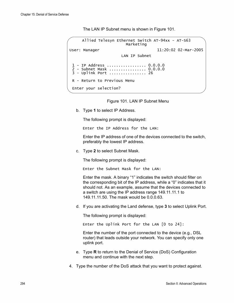
Chapter 15: Denial of Service Defense
The LAN IP Subnet menu is shown in Figure 101.
Figure 101. LAN IP Subnet Menu
b. Type 1 to select IP Address.
The following prompt is displayed:
Enter the IP Address for the LAN:
Enter the IP address of one of the devices connected to the switch, preferably the lowest IP address.
c. Type 2 to select Subnet Mask.
The following prompt is displayed:
Enter the Subnet Mask for the LAN:
Enter the mask. A binary “1” indicates the switch should filter on the corresponding bit of the IP address, while a “0” indicates that it should not. As an example, assume that the devices connected to a switch are using the IP address range 149.11.11.1 to 149.11.11.50. The mask would be 0.0.0.63.
d. If you are activating the Land defense, type 3 to select Uplink Port.
The following prompt is displayed:
Enter the Uplink Port for the LAN [0 to 24]:
Enter the number of the port connected to the device (e.g., DSL router) that leads outside your network. You can specify only one uplink port.
e. Type R to return to the Denial of Service (DoS) Configuration menu and continue with the next step.
4. Type the number of the DoS attack that you want to protect against.
Allied Telesyn Ethernet Switch AT-94xx - AT-S63Marketing
User: Manager 11:20:02 02-Mar-2005
LAN IP Subnet
1 - IP Address ................. 0.0.0.02 - Subnet Mask ................ 0.0.0.03 - Uplink Port ................ 26
R - Return to Previous Menu
Enter your selection?
294 Section II: Advanced Operations
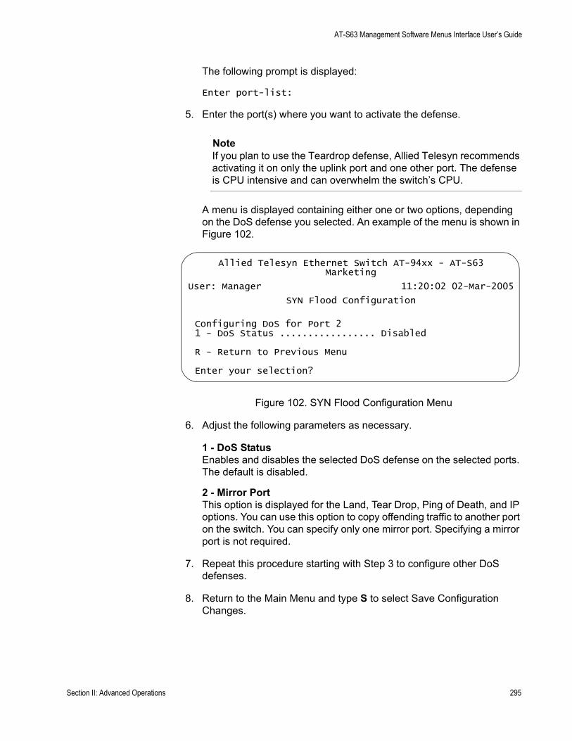
AT-S63 Management Software Menus Interface User’s Guide
The following prompt is displayed:
Enter port-list:
5. Enter the port(s) where you want to activate the defense.
NoteIf you plan to use the Teardrop defense, Allied Telesyn recommends activating it on only the uplink port and one other port. The defense is CPU intensive and can overwhelm the switch’s CPU.
A menu is displayed containing either one or two options, depending on the DoS defense you selected. An example of the menu is shown in Figure 102.
Figure 102. SYN Flood Configuration Menu
6. Adjust the following parameters as necessary.
1 - DoS StatusEnables and disables the selected DoS defense on the selected ports. The default is disabled.
2 - Mirror PortThis option is displayed for the Land, Tear Drop, Ping of Death, and IP options. You can use this option to copy offending traffic to another port on the switch. You can specify only one mirror port. Specifying a mirror port is not required.
7. Repeat this procedure starting with Step 3 to configure other DoS defenses.
8. Return to the Main Menu and type S to select Save Configuration Changes.
Allied Telesyn Ethernet Switch AT-94xx - AT-S63Marketing
User: Manager 11:20:02 02-Mar-2005
SYN Flood Configuration
Configuring DoS for Port 21 - DoS Status ................. Disabled
R - Return to Previous Menu
Enter your selection?
Section II: Advanced Operations 295

Chapter 15: Denial of Service Defense
296 Section II: Advanced Operations
Chapter 16
Quality of Service
This chapter describes Quality of Service (QoS). Sections in the chapter include:
“Quality of Service Overview” on page 298“Managing Flow Groups” on page 313“Managing Traffic Classes” on page 320“Managing Policies” on page 330
Section II: Advanced Operations 297
Chapter 16: Quality of Service
Quality of Service Overview
Quality of Service enables you to prioritize traffic and/or limit the bandwidth available to it. The concept of QoS is a departure from the original networking protocols, which treated all traffic on the Internet or within a LAN in the same manner. Without QoS, every traffic type is equally likely to be dropped if a link becomes oversubscribed. This approach is now inadequate in many networks, because traffic levels have increased and networks transport time-critical applications such as streams of video and data. QoS also enables service providers to easily supply different customers with different amounts of bandwidth.
Configuring Quality of Service involves two separate stages:
Classifying traffic into flows, according to a wide range of criteria.
Classification is performed by the switch’s packet classifiers, described in Chapter 13, “Classifiers” on page 251.
Acting on these traffic flows.
Quality of Service is a broadly used term that encompasses as a minimum both Layer 2 and Layer 3 in the OSI model. QoS is typically demonstrated by how the switch accomplishes the following:
Assigns priority to incoming frames, if they do not carry priority informationMaps prioritized frames to traffic classes, or maps frames to traffic classes based upon other criteriaMaps traffic classes to egress queues, or maps prioritized frames to egress queuesProvides maximum bandwidth limiting for traffic classes, egress queues and/or portsSchedules frames in egress queues for transmission (for example, empty queues in strict priority or samples each queue)Relabels the priority of framesDetermines which frames to drop if the network becomes congestedReserves memory for switching/routing or QoS operation (e.g. reserving buffers for egress queues, or buffers to store packets with particular characteristics)
NoteQoS is only performed on packets that are switched at wire speed. This includes IP, IP multicast, IPX, and Layer 2 traffic within VLANs.
The QoS functionality described in this chapter sorts packets into various
298 Section II: Advanced Operations

AT-S63 Management Software Menus Interface User’s Guide
flows, according to the QoS policy that applies to the port the traffic is received on. The switch then allocates resources to direct this traffic according to bandwidth or priority settings in the policy. A policy contains traffic classes, flow groups, and classifiers. Therefore, to configure QoS, you:
Create classifiers to sort packets into traffic flows.Create flow groups and add classifiers to them. Flow groups are groups of classifiers which group together similar traffic flows. You can apply QoS prioritization to flow groups and/or replace the traffic’s DiffServ Code Point.Create traffic classes and add flow groups to them. Traffic classes are groups of flow groups and are central to QoS. You can apply bandwidth limits and QoS prioritization to traffic classes, and/or replace the traffic’s DiffServ Code Point.Create policies and add traffic classes to them. Policies are groups of traffic classes. A policy defines a complete QoS solution for a port or group of ports.Associate policies with ports.
NoteThe steps listed above are in a conceptually logical order, but the switch cannot check a policy for errors until the policy is attached to a port. To simplify error diagnosis, define your QoS configuration on paper first, and then enter it into the management software starting with classifiers.
Policies, traffic classes, and flow groups are created as individual entities. When a traffic class is added to a policy, a logical link is created between the two entities. Destroying the policy unlinks the traffic class, leaving the traffic class in an unassigned state. Destroying a policy does not destroy any of the underlying entities. Similarly, destroying a traffic class unlinks flow groups, and destroying flow groups unlinks classifiers.
Classifiers Classifiers identify a particular traffic flow, and range from general to specific. (See Chapter 13, “Classifiers” on page 251 for more information.) Note that a single classifier should not be used in different flows that will end up, through traffic classes, assigned to the same policy. A classifier should only be used once per policy. Traffic is matched in the order of classifiers. For example, if a flow group has classifiers 1, 3, 2 and 5, that is the order in which the packets are matched.
Flow Groups Flow groups group similar traffic flows together, and allow more specific QoS controls to be used, in preference to those specified by the traffic class. Flow groups consist of a small set of QoS parameters and a group of classifiers. After a flow group has been added to a traffic class it cannot be added to another traffic class. A traffic class may have many flow
Section II: Advanced Operations 299
Chapter 16: Quality of Service
groups. Traffic is matched in the order of the flow groups. For example, if a traffic class has flow groups 1, 3, 2 and 5, this is the order in which the packets are matched.
QoS controls at the flow group level provide a QoS hierarchy. Non-default flow group settings are always used, but if no setting is specified for a flow group, the flow group uses the settings for the traffic class to which it belongs. For example, you can use a traffic class to limit the bandwidth available to web and FTP traffic combined. Within that traffic class, you can create two different flow groups with different priorities, to give web traffic a higher priority than FTP. Web traffic would then be given preferential access to bandwidth, but would be limited to the bandwidth limit of the traffic class.
Traffic Classes Traffic classes are the central component of the QoS solution. They provide most of the QoS controls that allow a QoS solution to be deployed. A traffic class can be assigned to only one policy. Traffic classes consist of a set of QoS parameters and a group of QoS flow groups. Traffic can be prioritized, marked (IP TOS or DSCP field set), and bandwidth limited. Traffic is matched in the order of traffic class. For example, if a policy has traffic classes 1, 3, 2 and 5, this is the order in which the packets are matched.
Policies QoS policies consist of a collection of user defined traffic classes. A policy can be assigned to more than one port, but a port may only have one policy.
QoS controls are applied to ingress traffic on ports. Therefore, to control a particular type of traffic, an appropriate QoS policy must be attached to each port that type of traffic ingresses. In most situations, the same policy can be applied to all ports, and to classify according to an egress port.
Note that the switch can only perform error checking of parameters and parameter values for the policy and its traffic classes and flow groups when the policy is set on a port.
QoS PolicyGuidelines
Following is a list of QoS policy guidelines:
A classifier may be assigned to many flow groups. However, assigning a classifier more than once within the same policy may lead to undesirable results. A classifier may be used successfully in many different policies.A flow group must be assigned at least one classifier but may have many classifiers.A flow group may only be assigned to one traffic class.A traffic class may have many flow groups.A traffic class may only be assigned to one policy.
300 Section II: Advanced Operations
AT-S63 Management Software Menus Interface User’s Guide
A policy may have many traffic classes.A policy may be assigned to many ports.A port may only have one policy.You can create a policy without assigning it to a port, but the policy will be inactive.A policy must have at least one action defined in the flow group, traffic class, or the policy itself. A policy without an action is invalid.The switch can store up to 64 flow groups.The switch can store up to 64 traffic classes.The switch can store up to 64 policies.
Packet Processing You can use the switch’s QoS tools to perform any combination of the following functions on a packet flow:
Limiting bandwidthPrioritizing packets to determine the level of precedence the switch will give to the packet for processingReplacing the VLAN tag User Priority to enable the next switch in the network to process the packet correctlyReplacing the TOS precedence or DSCP value to enable the next switch in the network to process the packet correctly.
BandwidthAllocation
Bandwidth limiting is configured at the level of traffic classes, and encompasses the flow groups contained in the traffic class. Traffic classes can be assigned maximum bandwidths, specified in kbps, Mbps, or Gbps.
PacketPrioritization
The switch has eight Class of Service (CoS) egress queues, numbered from 0 to 7. Queue 7 has the highest priority. When the switch becomes congested, it gives high priority queues precedence over lower-priority queues. When the switch has information about a packet’s priority, it sends the packet to the appropriate queue. You can specify the queue where the switch sends traffic, how much precedence each queue has, and whether priority remapping is written into the packet’s header for the next hop to use.
Prioritizing packets cannot improve your network’s performance when bandwidth is over-subscribed to the point that egress queues are always full. If one type of traffic is causing the congestion, you can limit its bandwidth. Other solutions are to increase bandwidth or decrease traffic.
You can set a packet’s priority by configuring a priority in the flow group or traffic class to which the packet belongs. The packet is put in the appropriate CoS queue for that priority. If the flow group and traffic class do not include a priority, the switch can determine the priority from the VLAN tag User Priority field of incoming tagged packets. The packet is put
Section II: Advanced Operations 301
Chapter 16: Quality of Service
in the appropriate CoS queue for its VLAN tag User Priority field. If neither the traffic class / flow group priority nor the VLAN tag User Priority is set, the packet is sent to the default queue, queue 1.
Both the VLAN tag User Priority and the traffic class / flow group priority setting allow eight different priority values (0-7). These eight priorities are mapped to the switch’s eight CoS queues. The switch’s default mapping is shown in Table 6 on page 339. Note that priority 0 is mapped to CoS queue 1 instead of CoS queue 0 because tagged traffic that has never been prioritized has a VLAN tag User Priority of 0. If priority 0 was mapped to CoS queue 0, this default traffic goes to the lowest queue, which is probably undesirable. This mapping also makes it possible to give some traffic a lower priority than the default traffic.
ReplacingPriorities
The traffic class or flow group priority (if set) determines the egress queue a packet is sent to when it egresses the switch, but by default has no effect on how the rest of the network processes the packet. To permanently change the packet’s priority, you need to replace one of two priority fields in the packet header:
The User Priority field of the VLAN tag header. Replacing this field relabels VLAN-tagged traffic, so that downstream switches can process it appropriately. Replacing this field is most useful outside DiffServ domains.The DSCP value of the IP header’s TOS byte (Figure 81 on page 255). Replacing this field may be required as part of the configuration of a DiffServ domain. See “DiffServ Domains” on page 303 for information on using the QoS policy model and the DSCP value to configure a DiffServ domain.
VLAN Tag UserPriorities
Within a flow group or traffic class, the VLAN tag User Priority value of incoming packets can be replaced with the priority specified in the flow group or traffic class. Replacement occurs before the packet is queued, so this priority also sets the queue priority.
DSCP Values There are three methods for replacing the DSCP byte of an incoming packet. You can use these methods together or separately. They are described in the order in which the switch performs them.
The DSCP value can be overwritten at ingress, for all traffic in a policy.The DSCP value in the packet can be replaced at the traffic class or flow group level.You can use these two replacements together at the edge of a DiffServ domain, to initialize incoming traffic.The DSCP value in a flow of packets can replaced if the bandwidth allocated to that traffic class is exceeded. This option allows the next switch in the network to identify traffic that exceeded the bandwidth allocation.
302 Section II: Advanced Operations

AT-S63 Management Software Menus Interface User’s Guide
DiffServ Domains Differentiated Services (DiffServ) is a method of dividing IP traffic into classes of service, without requiring that every router in a network remember detailed information about traffic flows. DiffServ operates within a DiffServ domain, a network or subnet that is managed as a single QoS unit. Packets are classified according to user-specified criteria at the edge of the network, divided into classes, and assigned the required class of service. Then packets are marked with a Differentiated Services Code Point (DSCP) tag to indicate the class of service to which they belong. The DSCP value is written into the TOS field of the IP header. Routers within the network then use this DSCP value to classify packets and assign QoS appropriately. When a packet leaves the DiffServ domain, the DSCP value can be replaced with a value appropriate for the next DiffServ domain.
A simple example of this process is shown in Figure 103, for limiting the amount of bandwidth used by traffic from a particular IP address. In the domain shown, this bandwidth limit is supplied by the class of service represented by a DSCP value of 40. In the next DiffServ domain, this traffic is assigned to the class of service represented by a DSCP value of 3.
Figure 103. DiffServ Domain Example
To use the QoS tool set to configure a DiffServ domain:
1. As packets come into the domain at edge switches, replace their DSCP value, if required.
Classify the packets according to the required characteristics. For available options, see Chapter 13, “Classifiers” on page 251.Assign the classifiers to flow groups and the flow groups to traffic
Non-DiffServtraffic
Classify by source IP addressMark with DSCP=40
Limit bandwidth
DiffServ Domain
Classify by DSCP=40Limit bandwidth
Classify by DSCP=40Limit bandwidth
Re-mark to DSCP=3
Next DiffServdomain
Section II: Advanced Operations 303
Chapter 16: Quality of Service
classes, with a different traffic class for each DiffServ code point grouping within the DiffServ domain.Give each traffic class the priority and/or bandwidth limiting controls that are required for that type of packet within this part of the domain.Assign a DSCP value to each traffic class, to be written into the TOS field of the packet header.
2. On switches and routers within the DiffServ domain, classify packets according to the DSCP values that were assigned to traffic classes on the edge switches.
Assign the classifiers to flow groups and the flow groups to traffic classes, with a different traffic class for each DiffServ code point grouping within the DiffServ domain.Give each traffic class the priority and/or bandwidth limiting controls that are required for that type of packet within this part of the domain. These QoS controls need not be the same for each switch.
3. As packets leave the DiffServ domain, classify them according to the DSCP values.
Assign the classifiers to flow groups and the flow groups to traffic classes, with a different traffic class for each DiffServ code point grouping within the DiffServ domain.Give each traffic class the priority and/or bandwidth limiting controls required for transmission of that type of packet to its next destination, in accordance with any Service Level Agreement (SLA) with the providers of that destination.If necessary, assign a different DSCP value to each traffic class, to be written into the TOS field of the packet header, to match the DSCP or TOS priority values of the destination network.
304 Section II: Advanced Operations
AT-S63 Management Software Menus Interface User’s Guide
Examples The following examples demonstrate how to implement QoS in three situations:
“Voice Applications,” next“Video Applications” on page 308“Critical Database” on page 310
Voice Applications
Voice applications typically require a small but consistent bandwidth. They are sensitive to latency (interpacket delay) and jitter (delivery delay). Voice applications can be set up to have the highest priority.
This example creates two policies that ensure low latency for all traffic sent by and destined to a voice application located on a node with the IP address 149.44.44.44. The policies raise the priority level of the packets to 7, the highest level. Policy 6 is for traffic from the application that enter the switch on port 1. Policy 11 is for traffic arriving on port 8 going to the
Section II: Advanced Operations 305
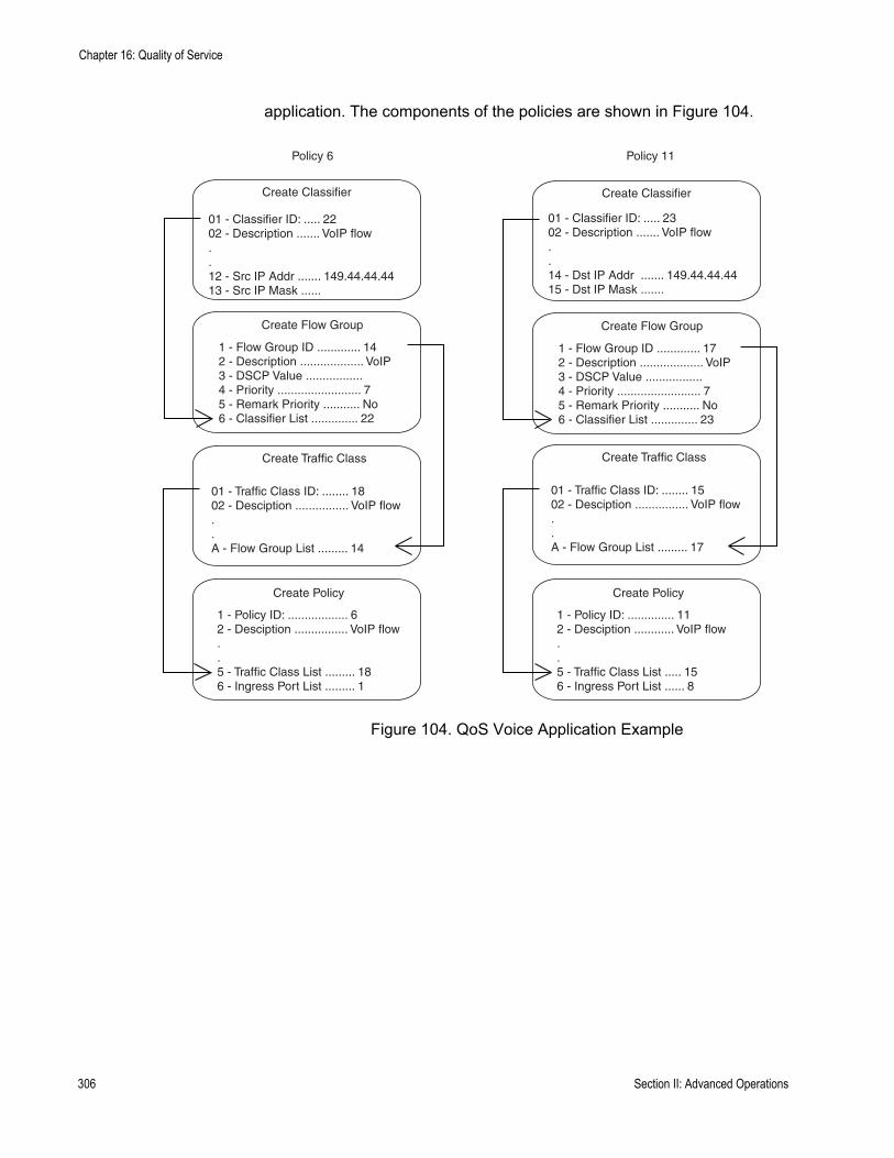
Chapter 16: Quality of Service
application. The components of the policies are shown in Figure 104.
Figure 104. QoS Voice Application Example
Create Classifier
01 - Classifier ID: ..... 2202 - Description ....... VoIP flow..12 - Src IP Addr ....... 149.44.44.4413 - Src IP Mask ......
Create Flow Group
1 - Flow Group ID ............. 142 - Description ................... VoIP3 - DSCP Value ................. 4 - Priority ......................... 75 - Remark Priority ........... No6 - Classifier List .............. 22
Create Traffic Class
01 - Traffic Class ID: ........ 1802 - Desciption ................ VoIP flow..A - Flow Group List ......... 14
Create Policy
1 - Policy ID: .................. 62 - Desciption ................ VoIP flow..5 - Traffic Class List ......... 186 - Ingress Port List ......... 1
Create Classifier
01 - Classifier ID: ..... 2302 - Description ....... VoIP flow..14 - Dst IP Addr ....... 149.44.44.4415 - Dst IP Mask .......
Create Flow Group
1 - Flow Group ID ............. 172 - Description ................... VoIP3 - DSCP Value ................. 4 - Priority ......................... 75 - Remark Priority ........... No6 - Classifier List .............. 23
Create Traffic Class
01 - Traffic Class ID: ........ 1502 - Desciption ................ VoIP flow..A - Flow Group List ......... 17
Create Policy
1 - Policy ID: .............. 112 - Desciption ............ VoIP flow..5 - Traffic Class List ..... 156 - Ingress Port List ...... 8
Policy 6 Policy 11
306 Section II: Advanced Operations
AT-S63 Management Software Menus Interface User’s Guide
The parts of the policies are:
Classifier - Defines the traffic flow by specifying the IP address of the node with the voice application. The classifier for Policy 6 specifies the address as a source address because this classifier is part of a policy for packets coming from the application. The classifier for Policy 11 specifies the address as a destination address because this classifier is part of a policy for packets going to the application.Flow Group - Specifies the new priority level of 7 for the packets. In this example, the packets leave the switch with the same priority level they had when they entered. The new priority level is relevant only as the packets traverse the switch. To alter the packets so that they leave containing the new level, you would change option 5, Remark Priority, to Yes. Traffic Class - No action is taken by the traffic class, other than to specify the flow group. Traffic class has a priority setting that you can use to override the priority level of packets, just as in a flow group. If you enter a priority value in both places, the setting in the flow group overrides the setting in the traffic class. Policy - Specifies the traffic class and the port to which the policy is to be assigned. Policy 6 is applied to port 1 because this is where the application is located. Policy 11 is applied to port 8 because this is where traffic going to the application will be received.
Section II: Advanced Operations 307
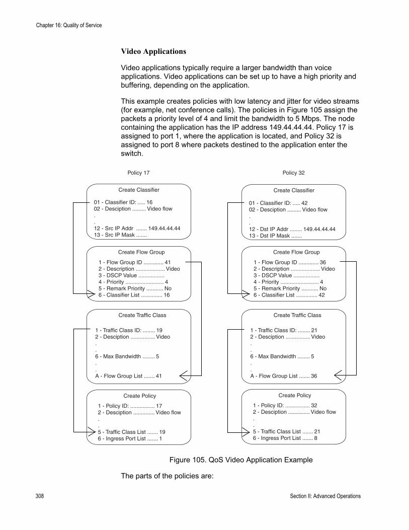
Chapter 16: Quality of Service
Video Applications
Video applications typically require a larger bandwidth than voice applications. Video applications can be set up to have a high priority and buffering, depending on the application.
This example creates policies with low latency and jitter for video streams (for example, net conference calls). The policies in Figure 105 assign the packets a priority level of 4 and limit the bandwidth to 5 Mbps. The node containing the application has the IP address 149.44.44.44. Policy 17 is assigned to port 1, where the application is located, and Policy 32 is assigned to port 8 where packets destined to the application enter the switch.
Figure 105. QoS Video Application Example
The parts of the policies are:
Create Classifier
01 - Classifier ID: ..... 1602 - Desciption ......... Video flow..12 - Src IP Addr ....... 149.44.44.4413 - Src IP Mask .......
Create Flow Group
1 - Flow Group ID ............. 412 - Description ................... Video3 - DSCP Value ................. 4 - Priority ......................... 45 - Remark Priority ........... No6 - Classifier List .............. 16
Create Traffic Class
1 - Traffic Class ID: ........ 192 - Desciption ................ Video..6 - Max Bandwidth ........ 5..A - Flow Group List ....... 41
Create Policy
1 - Policy ID: ................ 172 - Desciption .............. Video flow..5 - Traffic Class List ....... 196 - Ingress Port List ....... 1
Create Classifier
01 - Classifier ID: ..... 4202 - Desciption ......... Video flow..12 - Dst IP Addr ........ 149.44.44.4413 - Dst IP Mask .......
Create Flow Group
1 - Flow Group ID ............. 362 - Description ................... Video3 - DSCP Value ................. 4 - Priority ......................... 45 - Remark Priority ........... No6 - Classifier List .............. 42
Create Traffic Class
1 - Traffic Class ID: ........ 212 - Desciption ................ Video..6 - Max Bandwidth ........ 5..A - Flow Group List ....... 36
Create Policy
1 - Policy ID: ................ 322 - Desciption .............. Video flow..5 - Traffic Class List ....... 216 - Ingress Port List ....... 8
Policy 17 Policy 32
308 Section II: Advanced Operations

AT-S63 Management Software Menus Interface User’s Guide
Classifier - Specifies the IP address of the node with a video application. The classifier for Policy 17 specifies the address as a source address since this classifier is part of a policy concerning packets coming from the application. The classifier for Policy 32 specifies the address as a destination address because this classifier is part of a policy concerning packets going to the application.Flow Group - Specifies the new priority level of 4 for the packets. As with the previous example, the packets leave the switch with the same priority level they had when they entered. The new priority level is relevant only while the packets traverse the switch. To alter the packets so that they leave containing the new level, you would change option 5, Remark Priority, to Yes. Traffic Class - The packet stream is assigned a maximum bandwidth of 5 Mbps. Bandwidth assignment can only be made at the traffic class level.Policy - Specifies the traffic class and the port where the policy is to be assigned.
Section II: Advanced Operations 309

Chapter 16: Quality of Service
Critical Database
Critical databases typically require a high bandwidth. They also typically require less priority than either voice or video.
The policies in Figure 106 assign 50 Mbps bandwidth, with no change to priority, to traffic going to and from a database. The database is located on a node with the IP address 149.44.44.44 on port 1 of the switch.
Figure 106. QoS Critical Database Example
Create Classifier
01 - Classifier ID: ..... 4202 - Description ....... Database..12 - Src IP Addr ...... 149.44.44.4413 - Src IP Mask .....
Create Flow Group
1 - Flow Group ID ............. 362 - Description ................... Database3 - DSCP Value ................. 4 - Priority ......................... 5 - Remark Priority ........... No6 - Classifier List .............. 42
Create Traffic Class
1 - Traffic Class ID: ........ 212 - Description ............... Database..6 - Max Bandwidth ........ 50..A - Flow Group List ....... 36
Create Policy
1 - Policy ID: ................ 152 - Description ............. Database..5 - Traffic Class List ....... 216 - Ingress Port List ....... 1
Create Classifier
01 - Classifier ID: ..... 1002 - Description ........ Database..14 - Dst IP Addr ....... 149.44.44.4415 - Dst IP Mask ......
Create Flow Group
1 - Flow Group ID ............. 122 - Description ................... Database3 - DSCP Value ................. 4 - Priority ......................... 5 - Remark Priority ........... No6 - Classifier List .............. 10
Create Traffic Class
1 - Traffic Class ID: ........ 172 - Description ............... Database..6 - Max Bandwidth ........ 50..A - Flow Group List ....... 12
Create Policy
1 - Policy ID: ................ 172 - Description ............. Database..5 - Traffic Class List ....... 176 - Ingress Port List ....... 8
Policy 15 Policy 17
310 Section II: Advanced Operations
AT-S63 Management Software Menus Interface User’s Guide
Policy Component Hierarchy
The purpose of this example is to illustrate the hierarchy that exists among the components of a QoS policy and how that hierarchy needs to be taken into account when assigning new priority and DSCP values. A new priority can be set at the flow group and traffic class levels, while a new DSCP value can be set at all three levels—flow group, traffic class and policy. The basic rules are:
A new setting in a flow group takes precedence over a corresponding setting in a traffic class or policy.A new setting in a traffic class takes precedence over a corresponding setting in a policy.A new setting in a policy is used only if there is no corresponding setting in a flow group or traffic class.
This concept is illustrated in Figure 107 on page 312. It shows a policy for a series of traffic flows consisting of subnets defined by their destination IP addresses. New DSCP values for the traffic flows are established at different levels within the policy.
Traffic flows 149.11.11.0 and 149.22.22.0, defined by classifiers 1 and 2, are attached to a flow group, traffic class, and policy that contain new DSCP values. Because a setting in a flow group takes precedence over that of a traffic class or policy, the value in the flow group is used. The result is that the DSCP value in the two traffic flows is changed to 10.
The flow group for traffic flows 149.33.33.0 and 149.44.44.0, defined in classifiers 3 and 4, does not contain a new DSCP value. Therefore, the new value in the traffic class is used, in this case 30. The policy also has a DSCP setting, but it is not used for these traffic flows because a new DSCP setting in a traffic class takes precedence over that of a policy.
Finally, the new DSCP value for traffic flows 149.55.55.0 and 149.66.66.0, defined in classifiers 5 and 6, is set at the policy level to a value of 55 because the flow group and traffic class do not specify a new value.
Section II: Advanced Operations 311

Chapter 16: Quality of Service
Figure 107. Policy Component Hierarchy Example
Create Classifier
01 - Classifier ID: ..... 1.14 - Dst IP Addr ..... 149.11.11.015 - Dst IP Mask ..... 255.255.255.0
Create Flow Group
1 - Flow Group ID ......... 1.3 - DSCP Value ............. 10.6 - Classifier List ............1,2
Create Traffic Class
1 - Traffic Class ID: ........ 1.5 - DSCP value ............. 30.A - Flow Group List ....... 1,2
Create Policy
1 - Policy ID: ................ 1.3 - Remark DSCP ........ All4 - DSCP value ............ 555 - Traffic Class List ..... 1,2
Create Classifier
01 - Classifier ID: ..... 2.14 - Dst IP Addr ..... 149.22.22.015 - Dst IP Addr ...... 255.255.255.0
Create Classifier
01 - Classifier ID: ..... 3.14 - Dst IP Addr ..... 149.33.33.015 - Dst IP Mask .... 255.255.255.0
Create Classifier
01 - Classifier ID: ..... 4.14 - Dst IP Addr ....... 149.44.44.015 - Dst IP Addr ....... 255.255.255.0
Create Classifier
01 - Classifier ID: ..... 5.14 - Dst IP Addr ....... 149.55.55.015 - Dst IP Mask ...... 255.255.255.0
Create Classifier
01 - Classifier ID: ..... 6.14 - Dst IP Addr ..... 149.66.66.015 - Dst IP Mask ...... 255.255.255.0
Create Flow Group
1 - Flow Group ID ......... 2.3 - DSCP Value ............. .6 - Classifier List ............3,4
Create Flow Group
1 - Flow Group ID ......... 3.3 - DSCP Value ............. .6 - Classifier List ............5,6
Create Traffic Class
1 - Traffic Class ID: ........ 2.5 - DSCP value ............. .A - Flow Group List ....... 3
312 Section II: Advanced Operations

AT-S63 Management Software Menus Interface User’s Guide
Managing Flow Groups
This section contains the following procedures:
“Creating a Flow Group,” next“Modifying a Flow Group” on page 315“Deleting a Flow Group” on page 317“Displaying Flow Groups” on page 318
Creating a FlowGroup
To create a flow group, perform the following procedure:
1. From the Main Menu, type 7 to select Security and Services.
The Security and Services menu is shown in Figure 82 on page 259.
2. From the Security and Services menu, type 6 to select Quality of Service.
The Quality of Service (QoS) menu is shown in Figure 108.
Figure 108. Quality of Service (QoS) menu
3. From the Quality of Service (QoS) menu, type 1 to select Flow Group Configuration.
Allied Telesyn Ethernet Switch AT-94xx - AT-S63Marketing
User: Manager 11:20:02 02-Mar-2005
Quality of Service (QoS)
1 - Flow Group Configuration2 - Traffic Class Configuration3 - Policy Configuration
R - Return to Previous Menu
Enter your selection?
Section II: Advanced Operations 313

Chapter 16: Quality of Service
The Flow Group Configuration menu is shown in Figure 109.
Figure 109. Flow Group Configuration Menu
4. From the Flow Group Configuration menu, type 1 to select Create Flow Group.
The Create Flow Group menu is shown in Figure 110.
Figure 110. Create Flow Group Menu
5. Configure the following parameters as desired:
1 - Flow Group IDSpecifies an ID number for the flow group. Each flow group on the switch must have a unique number. The range is 0 to 1023. The default is 0. This parameter is required.
2 - DescriptionSpecifies a description for the flow group. The description can be from 1 to 15 alphanumeric characters including spaces. This parameter is
Allied Telesyn Ethernet Switch AT-94xx - AT-S63Marketing
User: Manager 11:20:02 02-Mar-2005
Flow Group Configuration
1 - Create Flow Group2 - Modify Flow Group3 - Destroy Flow Group4 - Show Flow Groups
R - Return to Previous Menu
Enter your selection?
Allied Telesyn Ethernet Switch AT-94xx - AT-S63Marketing
User: Manager 11:20:02 02-Mar-2005
Create Flow Group
1 - Flow Group ID .............. 2 - Description ...............3 - DSCP value ................4 - Priority ..................5 - Remark Priority ........... 6 - Classifier List ...........
C - Create Flow GroupR - Return to Previous Menu
Enter your selection?
314 Section II: Advanced Operations

AT-S63 Management Software Menus Interface User’s Guide
optional, but recommended. Names can help you identify the groups on the switch.
3 - DSCP valueSpecifies a replacement value to write into the DSCP (TOS) field of the packets. The range is 0 to 63.
A new DSCP value can be set at all three levels: flow group, traffic class, and policy. A DSCP value specified in a flow group overrides a DSCP value specified at the traffic class or policy level.
4 - PrioritySpecifies a new user priority value for the packets. The range is 0 to 7. If you specify a new user priority value here and in Traffic Class, the value here overrides the value in Traffic Class. If you want the packets to retain the new value when they exit the switch, change option 5, Remark Priority, to Yes.
5 - Remark PriorityReplaces the user priority value in the packets with the new value specified in option 4, Priority, if set to Yes. If set to No, which is the default, the packets retain their preexisting priority level.
6 - Classifier ListSpecifies the classifiers to be assigned to the policy. The specified classifiers must already exist. Separate multiple classifier IDs with commas (e.g., 4,11,13).
6. After configuring the parameters, type C to select Create Flow Group.
7. To create another flow group, repeat this procedure starting with step 4. To assign the flow group to a traffic class, go to “Managing Traffic Classes” on page 320.
8. After making changes, type R until you return to the Main Menu. Then type S to select Save Configuration Changes.
Modifying a FlowGroup
To modify a flow group, perform the following procedure:
1. From the Main Menu, type 7 to select Security and Services.
The Security and Services menu is shown in Figure 82 on page 259.
2. From the Security and Services menu, type 6 to select Quality of Service.
The Quality of Service (QoS) menu is shown in Figure 108 on page 313.
3. From the Quality of Service (QoS) menu, type 1 to select Flow Group Configuration.
Section II: Advanced Operations 315

Chapter 16: Quality of Service
The Flow Group Configuration menu is shown in Figure 109 on page 314.
4. From the Flow Group Configuration menu, type 2 to select Modify Flow Group.
The following prompt is displayed:
Available Flow Group(s): 0-10Enter Flow Group ID : [0 to 1023] -> 0
5. Enter the ID number of the flow group you want to modify. You can modify only one flow group at a time.
The Modify Flow Group menu is shown in Figure 111.
Figure 111. Modify Flow Group Menu
6. Modify the settings as needed.
When you modify a flow group, note the following:
You cannot change the flow group ID number.To delete a value from a variable so as to leave it blank, select the variable and then use the backspace key to delete its default value.Specifying an invalid value for a parameter that already has a value causes the parameter to revert to its default value.
7. Type M to select Modify Flow Group.
8. To modify another flow group, repeat this procedure starting with step 4. To assign the flow group to a traffic class, go to “Managing Traffic Classes” on page 320.
Allied Telesyn Ethernet Switch AT-94xx - AT-S63Marketing
User: Manager 11:20:02 02-Mar-2005
Modify Flow Group
1 - Flow Group ID .............. 22 - Description ................ Video13 - DSCP value ................. 04 - Priority ................... 65 - Remark Priority ............ No6 - Classifier List ............ 11
M - Modify Flow GroupR - Return to Previous Menu
Enter your selection?
316 Section II: Advanced Operations
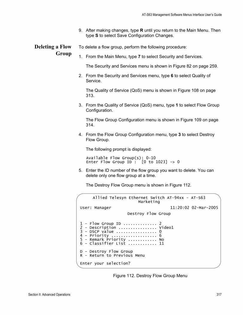
AT-S63 Management Software Menus Interface User’s Guide
9. After making changes, type R until you return to the Main Menu. Then type S to select Save Configuration Changes.
Deleting a FlowGroup
To delete a flow group, perform the following procedure:
1. From the Main Menu, type 7 to select Security and Services.
The Security and Services menu is shown in Figure 82 on page 259.
2. From the Security and Services menu, type 6 to select Quality of Service.
The Quality of Service (QoS) menu is shown in Figure 108 on page 313.
3. From the Quality of Service (QoS) menu, type 1 to select Flow Group Configuration.
The Flow Group Configuration menu is shown in Figure 109 on page 314.
4. From the Flow Group Configuration menu, type 3 to select Destroy Flow Group.
The following prompt is displayed:
Available Flow Group(s): 0-10Enter Flow Group ID : [0 to 1023] -> 0
5. Enter the ID number of the flow group you want to delete. You can delete only one flow group at a time.
The Destroy Flow Group menu is shown in Figure 112.
Figure 112. Destroy Flow Group Menu
Allied Telesyn Ethernet Switch AT-94xx - AT-S63Marketing
User: Manager 11:20:02 02-Mar-2005
Destroy Flow Group
1 - Flow Group ID .............. 22 - Description ................ Video13 - DSCP value ................. 04 - Priority ................... 65 - Remark Priority ............ No6 - Classifier List ............ 11
D - Destroy Flow GroupR - Return to Previous Menu
Enter your selection?
Section II: Advanced Operations 317
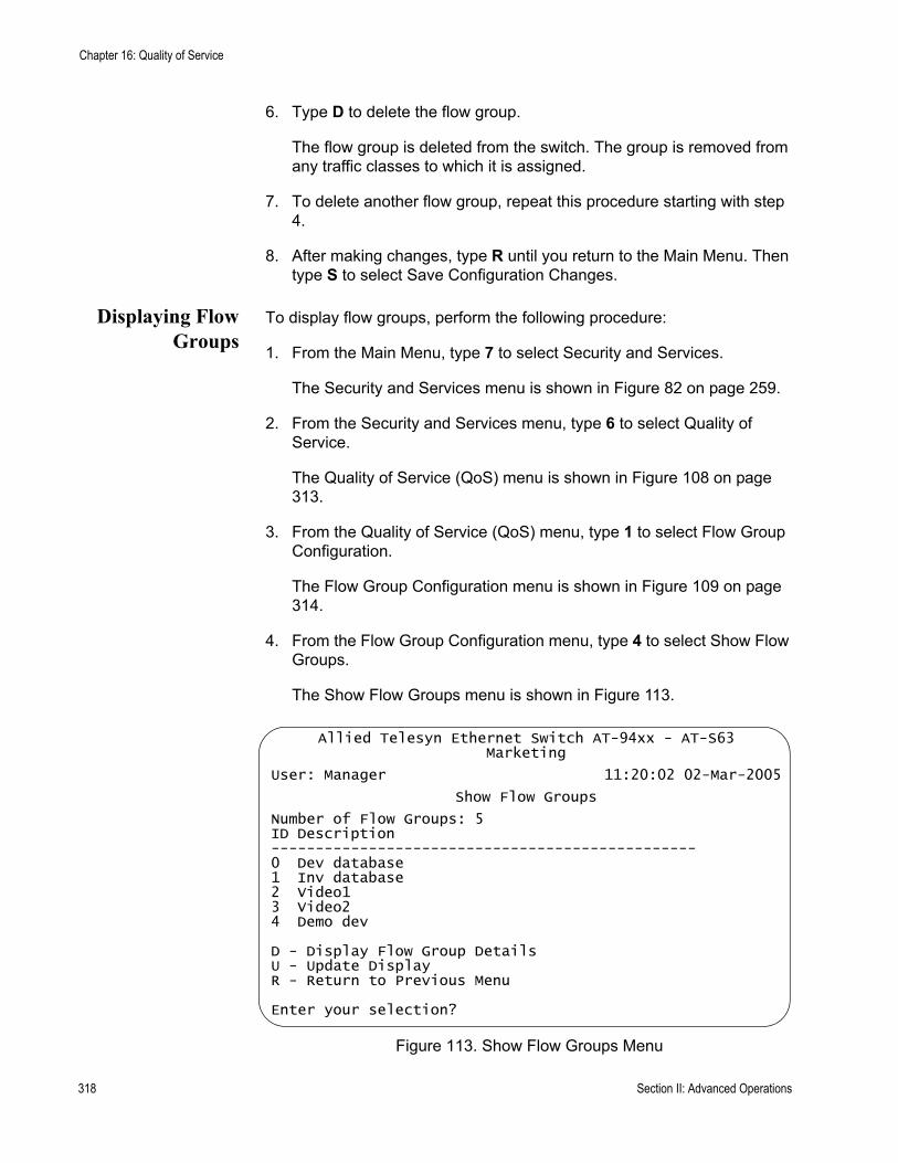
Chapter 16: Quality of Service
6. Type D to delete the flow group.
The flow group is deleted from the switch. The group is removed from any traffic classes to which it is assigned.
7. To delete another flow group, repeat this procedure starting with step 4.
8. After making changes, type R until you return to the Main Menu. Then type S to select Save Configuration Changes.
Displaying FlowGroups
To display flow groups, perform the following procedure:
1. From the Main Menu, type 7 to select Security and Services.
The Security and Services menu is shown in Figure 82 on page 259.
2. From the Security and Services menu, type 6 to select Quality of Service.
The Quality of Service (QoS) menu is shown in Figure 108 on page 313.
3. From the Quality of Service (QoS) menu, type 1 to select Flow Group Configuration.
The Flow Group Configuration menu is shown in Figure 109 on page 314.
4. From the Flow Group Configuration menu, type 4 to select Show Flow Groups.
The Show Flow Groups menu is shown in Figure 113.
Figure 113. Show Flow Groups Menu
Allied Telesyn Ethernet Switch AT-94xx - AT-S63Marketing
User: Manager 11:20:02 02-Mar-2005
Show Flow Groups
Number of Flow Groups: 5ID Description------------------------------------------------0 Dev database1 Inv database2 Video13 Video24 Demo dev
D - Display Flow Group DetailsU - Update DisplayR - Return to Previous Menu
Enter your selection?
318 Section II: Advanced Operations
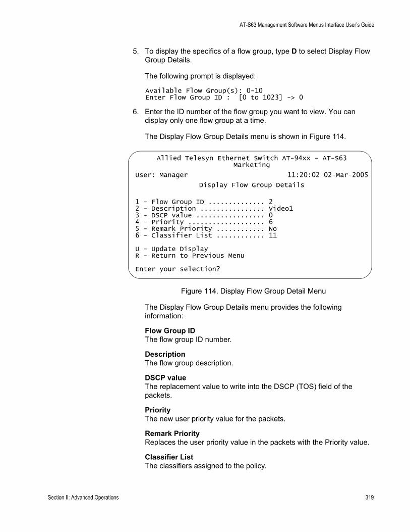
AT-S63 Management Software Menus Interface User’s Guide
5. To display the specifics of a flow group, type D to select Display Flow Group Details.
The following prompt is displayed:
Available Flow Group(s): 0-10Enter Flow Group ID : [0 to 1023] -> 0
6. Enter the ID number of the flow group you want to view. You can display only one flow group at a time.
The Display Flow Group Details menu is shown in Figure 114.
Figure 114. Display Flow Group Detail Menu
The Display Flow Group Details menu provides the following information:
Flow Group IDThe flow group ID number.
DescriptionThe flow group description.
DSCP valueThe replacement value to write into the DSCP (TOS) field of the packets.
PriorityThe new user priority value for the packets.
Remark PriorityReplaces the user priority value in the packets with the Priority value.
Classifier ListThe classifiers assigned to the policy.
Allied Telesyn Ethernet Switch AT-94xx - AT-S63Marketing
User: Manager 11:20:02 02-Mar-2005
Display Flow Group Details
1 - Flow Group ID .............. 22 - Description ................ Video13 - DSCP value ................. 04 - Priority ................... 65 - Remark Priority ............ No6 - Classifier List ............ 11
U - Update DisplayR - Return to Previous Menu
Enter your selection?
Section II: Advanced Operations 319
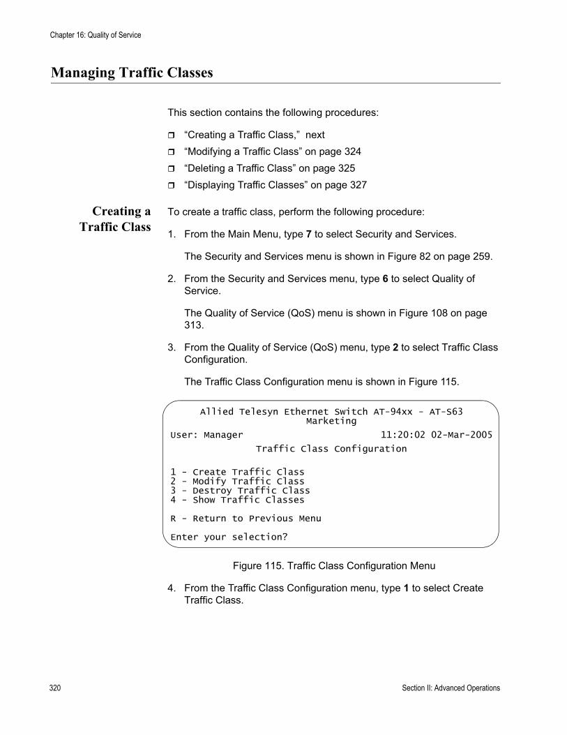
Chapter 16: Quality of Service
Managing Traffic Classes
This section contains the following procedures:
“Creating a Traffic Class,” next“Modifying a Traffic Class” on page 324“Deleting a Traffic Class” on page 325“Displaying Traffic Classes” on page 327
Creating aTraffic Class
To create a traffic class, perform the following procedure:
1. From the Main Menu, type 7 to select Security and Services.
The Security and Services menu is shown in Figure 82 on page 259.
2. From the Security and Services menu, type 6 to select Quality of Service.
The Quality of Service (QoS) menu is shown in Figure 108 on page 313.
3. From the Quality of Service (QoS) menu, type 2 to select Traffic Class Configuration.
The Traffic Class Configuration menu is shown in Figure 115.
Figure 115. Traffic Class Configuration Menu
4. From the Traffic Class Configuration menu, type 1 to select Create Traffic Class.
Allied Telesyn Ethernet Switch AT-94xx - AT-S63Marketing
User: Manager 11:20:02 02-Mar-2005
Traffic Class Configuration
1 - Create Traffic Class2 - Modify Traffic Class3 - Destroy Traffic Class4 - Show Traffic Classes
R - Return to Previous Menu
Enter your selection?
320 Section II: Advanced Operations
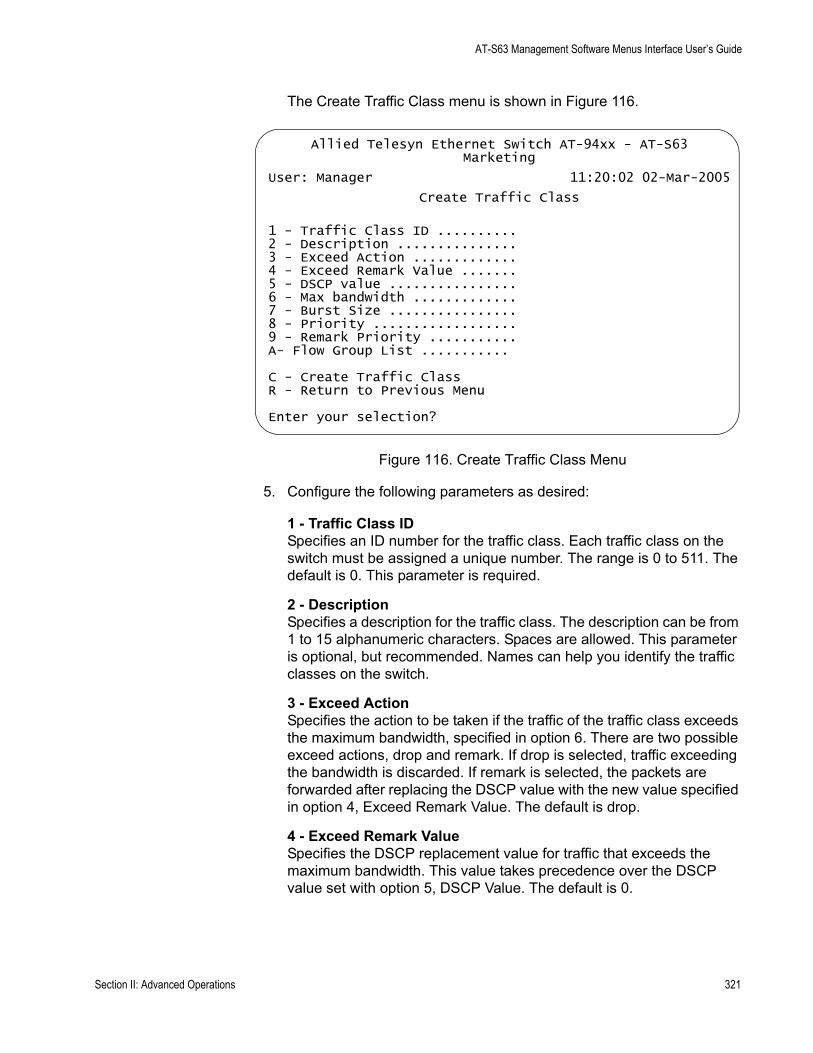
AT-S63 Management Software Menus Interface User’s Guide
The Create Traffic Class menu is shown in Figure 116.
Figure 116. Create Traffic Class Menu
5. Configure the following parameters as desired:
1 - Traffic Class IDSpecifies an ID number for the traffic class. Each traffic class on the switch must be assigned a unique number. The range is 0 to 511. The default is 0. This parameter is required.
2 - DescriptionSpecifies a description for the traffic class. The description can be from 1 to 15 alphanumeric characters. Spaces are allowed. This parameter is optional, but recommended. Names can help you identify the traffic classes on the switch.
3 - Exceed ActionSpecifies the action to be taken if the traffic of the traffic class exceeds the maximum bandwidth, specified in option 6. There are two possible exceed actions, drop and remark. If drop is selected, traffic exceeding the bandwidth is discarded. If remark is selected, the packets are forwarded after replacing the DSCP value with the new value specified in option 4, Exceed Remark Value. The default is drop.
4 - Exceed Remark ValueSpecifies the DSCP replacement value for traffic that exceeds the maximum bandwidth. This value takes precedence over the DSCP value set with option 5, DSCP Value. The default is 0.
Allied Telesyn Ethernet Switch AT-94xx - AT-S63Marketing
User: Manager 11:20:02 02-Mar-2005
Create Traffic Class
1 - Traffic Class ID .......... 2 - Description ............... 3 - Exceed Action ............. 4 - Exceed Remark Value ....... 5 - DSCP value ................ 6 - Max bandwidth ............. 7 - Burst Size ................ 8 - Priority .................. 9 - Remark Priority ........... A- Flow Group List ...........
C - Create Traffic ClassR - Return to Previous Menu
Enter your selection?
Section II: Advanced Operations 321

Chapter 16: Quality of Service
5 - DSCP valueSpecifies a replacement value to write into the DSCP (TOS) field of the packets. The range is 0 to 63.
A new DSCP value can be set at all three levels: flow group, traffic class, and policy. A DSCP value specified in a flow group overrides a DSCP value specified at the traffic class or policy level. A DSCP value specified at the traffic class level is used only if no value has been specified at the flow group level. It will override any value set at the policy level.
6 - Max BandwidthSpecifies the maximum bandwidth available to the traffic class. This parameter determines the maximum rate at which the ingress port accepts data belonging to this traffic class before either dropping or remarking occurs, depending on option 3, Exceed Action. If the sum of the maximum bandwidth for all traffic classes on a policy exceeds the (ingress) bandwidth of the port to which the policy is assigned, the bandwidth for the port takes precedence and the port discards packets before they can be classified. The range is 0 to 1016 Mbps.
The value for this parameter is rounded up to the nearest Mbps value when this traffic class is assigned to a policy on a 10/100 port, and up to the nearest 8 Mbps value when assigned to a policy on a gigabit port (for example, on a gigabit port, 1 Mbps is rounded to 8 Mbps, and 9 is rounded to 16).
NoteIf this option is set to 0 (zero), all traffic that matches that traffic class is dropped. However, a access control list can be created to match the traffic that is marked for dropping, or a subset of it, and given an action of permit, to override this. This functionality can be used to discard all but a certain type of traffic. For more information about configuring access control lists, see Chapter 14, “Access Control Lists” on page 269.
7 - Burst SizeSpecifies the size of a token bucket for the traffic class. The token bucket is used in situations where you have set a maximum bandwidth for a class, but where traffic activity may periodically exceed the maximum. A token bucket can provide a buffer for those periods where the maximum bandwidth is exceeded.
Tokens are added to the bucket at the same rate as the traffic class’ maximum bandwidth, set with option 6, Max Bandwidth. For example, a maximum bandwidth of 50 Mbps adds tokens to the bucket at that rate.
If the amount of traffic flow matches the maximum bandwidth, no traffic is dropped because the number of tokens added to the bucket
322 Section II: Advanced Operations

AT-S63 Management Software Menus Interface User’s Guide
matches the number being used by the traffic. However, no unused tokens will accumulate in the bucket. If the traffic increases, the excess traffic will be discarded since no tokens are available for handling the increase.
If the traffic is below the maximum bandwidth, unused tokens will accumulate in the bucket since the actual bandwidth falls below the specified maximum. The unused tokens will be available for handling excess traffic should the traffic exceed the maximum bandwidth. Should an increase in traffic continue to the point where all the unused tokens are used up, packets will be discarded.
Unused tokens accumulate in the bucket until the bucket reaches maximum capacity, set by this parameter. When the maximum capacity of the bucket is reached, no extra tokens are added. The range is 4 to 512 Kbps.
NoteTo use this parameter you must specify a maximum bandwidth using item 6 - Max Bandwidth. Specifying a token bucket size without also specifying a maximum bandwidth serves no function.
8 - PrioritySpecifies the priority value in the IEEE 802.1p tag control field that traffic belonging to this traffic class is assigned. Priority values range from 0 to 7 with 0 being the lowest priority and 7 being the highest priority. Incoming frames are mapped into one of four Class of Service (CoS) queues based on the priority value.
If you want the packets to retain the new value when they exit the switch, change option 9, Remark Priority, to Yes.
If you specify a new user priority value here and in Flow Group, the value in Flow Group overwrites the value here.
9 - Remark PriorityReplaces the user priority value in the packets with the new value specified in option 4, Priority, if set to Yes. If set to No, which is the default, the packets retain their preexisting priority level when they leave the switch.
A- Flow Group ListSpecifies the flow groups to be assigned to the traffic class. The specified flow groups must already exist. Separate multiple IDs with commas (e.g., 4,11,13).
6. After configuring the parameters, type C to select Create Traffic Class.
7. To create another traffic class, repeat this procedure starting with step 3. To assign the traffic class to a policy, go to “Managing Policies” on page 330.
Section II: Advanced Operations 323

Chapter 16: Quality of Service
8. After making changes, type R until you return to the Main Menu. Then type S to select Save Configuration Changes.
Modifying aTraffic Class
To modify a traffic class, perform the following procedure:
1. From the Main Menu, type 7 to select Security and Services.
The Security and Services menu is shown in Figure 82 on page 259.
2. From the Security and Services menu, type 6 to select Quality of Service.
The Quality of Service (QoS) menu is shown in Figure 108 on page 313.
3. From the Quality of Service (QoS) menu, type 2 to select Traffic Class Configuration.
The Traffic Class Configuration menu is shown in Figure 115 on page 320.
4. From the Traffic Class Configuration menu, type 2 to select Modify Traffic Class.
The following prompt is displayed:
Available Traffic Class(es): 0-7Enter Traffic Class ID : [0 to 511] -> 0
5. Enter the ID number of the traffic class you want to modify. You can modify only one traffic class at a time.
324 Section II: Advanced Operations

AT-S63 Management Software Menus Interface User’s Guide
The Modify Traffic Class menu is shown in Figure 117.
Figure 117. Modify Traffic Class Menu
6. Modify the settings as needed. For parameter definitions, refer to “Creating a Traffic Class” on page 320.
When you modify a traffic class, note the following:
You cannot change the traffic class ID number.To delete a value from a variable so as to leave it blank, select the variable and then use the backspace key to delete its default value.Specifying an invalid value for a parameter that already has a value causes the parameter to revert to its default value.
7. Type M to select Modify Traffic Class.
8. To modify another traffic class, repeat this procedure starting with step 4. To assign the traffic class to a policy, go to “Managing Policies” on page 330.
9. After making changes, type R until you return to the Main Menu. Then type S to select Save Configuration Changes.
Deleting a TrafficClass
To delete a traffic class, perform the following procedure:
1. From the Main Menu, type 7 to select Security and Services.
The Security and Services menu is shown in Figure 82 on page 259.
Allied Telesyn Ethernet Switch AT-94xx - AT-S63Marketing
User: Manager 11:20:02 02-Mar-2005
Modify Traffic Class
1 - Traffic Class ID .......... 02 - Description ............... Video23 - Exceed Action ............. Drop4 - Exceed Remark Value ....... 05 - DSCP value ................ 06 - Max bandwidth ............. 07 - Burst Size ................ 08 - Priority .................. 09 - Remark Priority ........... NoA - VLAN ID ................... 2B - Flow Group List ........... 23
M - Modify Traffic ClassR - Return to Previous Menu
Enter your selection?
Section II: Advanced Operations 325
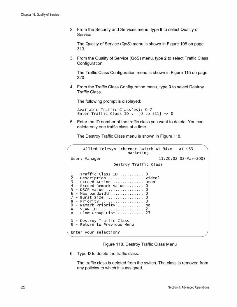
Chapter 16: Quality of Service
2. From the Security and Services menu, type 6 to select Quality of Service.
The Quality of Service (QoS) menu is shown in Figure 108 on page 313.
3. From the Quality of Service (QoS) menu, type 2 to select Traffic Class Configuration.
The Traffic Class Configuration menu is shown in Figure 115 on page 320.
4. From the Traffic Class Configuration menu, type 3 to select Destroy Traffic Class.
The following prompt is displayed:
Available Traffic Class(es): 0-7Enter Traffic Class ID : [0 to 511] -> 0
5. Enter the ID number of the traffic class you want to delete. You can delete only one traffic class at a time.
The Destroy Traffic Class menu is shown in Figure 118.
Figure 118. Destroy Traffic Class Menu
6. Type D to delete the traffic class.
The traffic class is deleted from the switch. The class is removed from any policies to which it is assigned.
Allied Telesyn Ethernet Switch AT-94xx - AT-S63Marketing
User: Manager 11:20:02 02-Mar-2005
Destroy Traffic Class
1 - Traffic Class ID .......... 02 - Description ............... Video23 - Exceed Action ............. Drop4 - Exceed Remark Value ....... 05 - DSCP value ................ 06 - Max bandwidth ............. 07 - Burst Size ................ 08 - Priority .................. 09 - Remark Priority ........... NoA - VLAN ID ................... 2B - Flow Group List ........... 23
D - Destroy Traffic ClassR - Return to Previous Menu
Enter your selection?
326 Section II: Advanced Operations
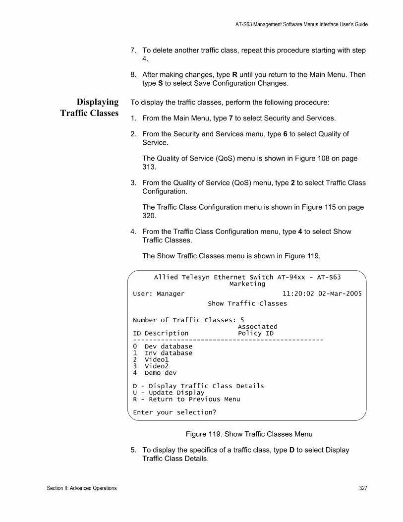
AT-S63 Management Software Menus Interface User’s Guide
7. To delete another traffic class, repeat this procedure starting with step 4.
8. After making changes, type R until you return to the Main Menu. Then type S to select Save Configuration Changes.
DisplayingTraffic Classes
To display the traffic classes, perform the following procedure:
1. From the Main Menu, type 7 to select Security and Services.
2. From the Security and Services menu, type 6 to select Quality of Service.
The Quality of Service (QoS) menu is shown in Figure 108 on page 313.
3. From the Quality of Service (QoS) menu, type 2 to select Traffic Class Configuration.
The Traffic Class Configuration menu is shown in Figure 115 on page 320.
4. From the Traffic Class Configuration menu, type 4 to select Show Traffic Classes.
The Show Traffic Classes menu is shown in Figure 119.
Figure 119. Show Traffic Classes Menu
5. To display the specifics of a traffic class, type D to select Display Traffic Class Details.
Allied Telesyn Ethernet Switch AT-94xx - AT-S63Marketing
User: Manager 11:20:02 02-Mar-2005
Show Traffic Classes
Number of Traffic Classes: 5Associated
ID Description Policy ID------------------------------------------------0 Dev database1 Inv database2 Video13 Video24 Demo dev
D - Display Traffic Class DetailsU - Update DisplayR - Return to Previous Menu
Enter your selection?
Section II: Advanced Operations 327
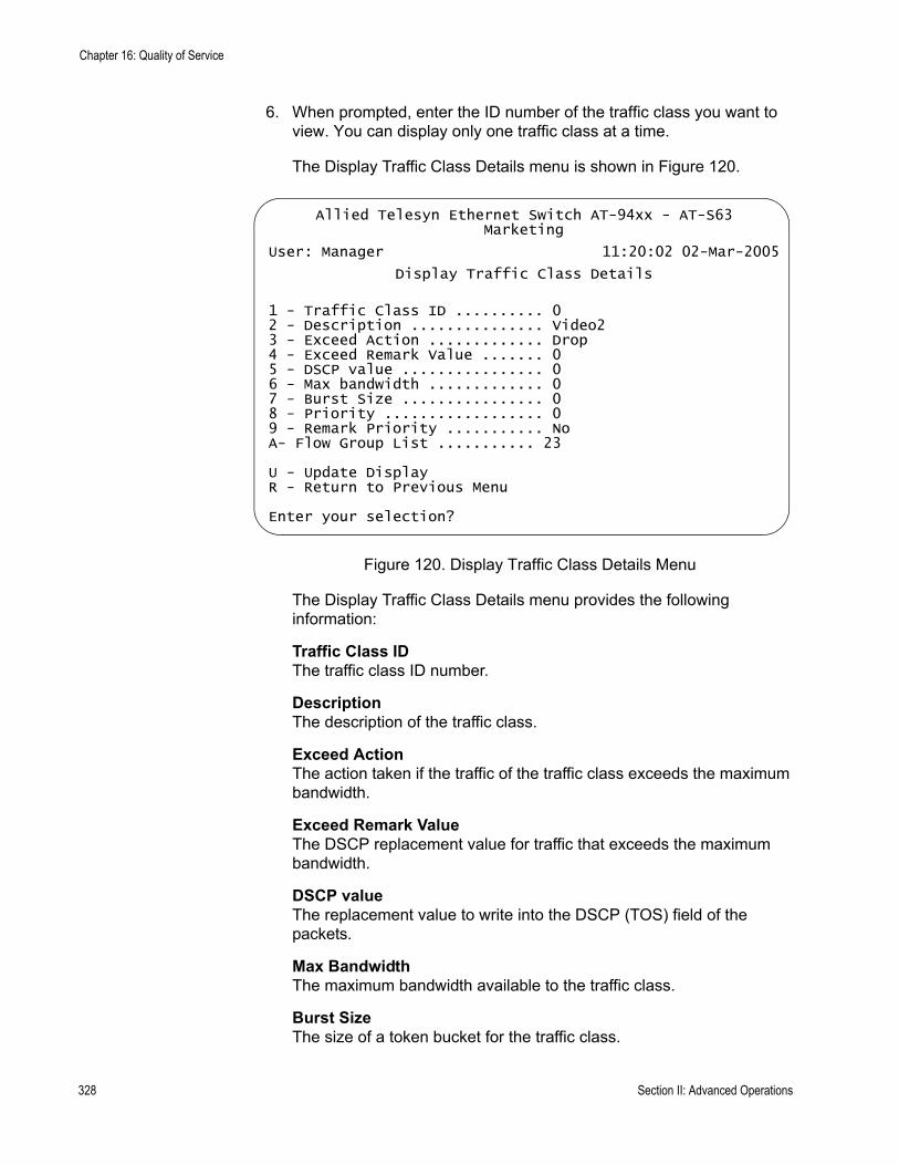
Chapter 16: Quality of Service
6. When prompted, enter the ID number of the traffic class you want to view. You can display only one traffic class at a time.
The Display Traffic Class Details menu is shown in Figure 120.
Figure 120. Display Traffic Class Details Menu
The Display Traffic Class Details menu provides the following information:
Traffic Class IDThe traffic class ID number.
DescriptionThe description of the traffic class.
Exceed ActionThe action taken if the traffic of the traffic class exceeds the maximum bandwidth.
Exceed Remark ValueThe DSCP replacement value for traffic that exceeds the maximum bandwidth.
DSCP valueThe replacement value to write into the DSCP (TOS) field of the packets.
Max BandwidthThe maximum bandwidth available to the traffic class.
Burst SizeThe size of a token bucket for the traffic class.
Allied Telesyn Ethernet Switch AT-94xx - AT-S63Marketing
User: Manager 11:20:02 02-Mar-2005
Display Traffic Class Details
1 - Traffic Class ID .......... 02 - Description ............... Video23 - Exceed Action ............. Drop4 - Exceed Remark Value ....... 05 - DSCP value ................ 06 - Max bandwidth ............. 07 - Burst Size ................ 08 - Priority .................. 09 - Remark Priority ........... NoA- Flow Group List ........... 23
U - Update DisplayR - Return to Previous Menu
Enter your selection?
328 Section II: Advanced Operations

AT-S63 Management Software Menus Interface User’s Guide
PriorityThe priority value in the IEEE 802.1p tag control field that traffic belonging to this traffic class is assigned.
Remark PriorityReplaces the user priority value in the packets with the Priority value.
Flow Group ListThe flow groups to be assigned to the traffic class.
Section II: Advanced Operations 329

Chapter 16: Quality of Service
Managing Policies
This section contains the following procedures:
“Creating a Policy,” next“Modifying a Policy” on page 332“Deleting a Policy” on page 333“Displaying Policies” on page 334
Creating a Policy To create a policy, perform the following procedure:
1. From the Main Menu, type 7 to select Security and Services.
The Security and Services menu is shown in Figure 82 on page 259.
2. From the Security and Services menu, type 6 to select Quality of Service.
The Quality of Service (QoS) menu is shown in Figure 108 on page 313.
3. From the Quality of Service (QoS) menu, type 3 to select Policy Configuration.
The Policy Configuration menu is shown in Figure 121.
Figure 121. Policy Configuration Menu
4. From the Policy Configuration menu, type 1 to select Create Policy.
Allied Telesyn Ethernet Switch AT-94xx - AT-S63Marketing
User: Manager 11:20:02 02-Mar-2005
Policy Configuration
1 - Create Policy2 - Modify Policy3 - Destroy Policy4 - Show Policies
R - Return to Previous Menu
Enter your selection?
330 Section II: Advanced Operations
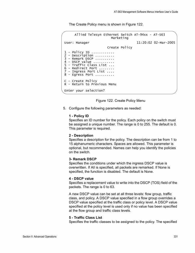
AT-S63 Management Software Menus Interface User’s Guide
The Create Policy menu is shown in Figure 122.
Figure 122. Create Policy Menu
5. Configure the following parameters as needed:
1 - Policy IDSpecifies an ID number for the policy. Each policy on the switch must be assigned a unique number. The range is 0 to 255. The default is 0. This parameter is required.
2 - DescriptionSpecifies a description for the policy. The description can be from 1 to 15 alphanumeric characters. Spaces are allowed. This parameter is optional, but recommended. Names can help you identify the policies on the switch.
3- Remark DSCPSpecifies the conditions under which the ingress DSCP value is overwritten. If All is specified, all packets are remarked. If None is specified, the function is disabled. The default is None.
4 - DSCP valueSpecifies a replacement value to write into the DSCP (TOS) field of the packets. The range is 0 to 63.
A new DSCP value can be set at all three levels: flow group, traffic class, and policy. A DSCP value specified in a flow group overrides a DSCP value specified at the traffic class or policy level. A DSCP value specified at the policy level is used only if no value has been specified at the flow group and traffic class levels.
5 - Traffic Class ListSpecifies the traffic classes to be assigned to the policy. The specified
Allied Telesyn Ethernet Switch AT-94xx - AT-S63Marketing
User: Manager 11:20:02 02-Mar-2005
Create Policy
1 - Policy ID ............ 2 - Description ..........3 - Remark DSCP ..........4 - DSCP value ...........5 - Traffic Class List ...6 - Redirect Port ........7 - Ingress Port List ....8 - Egress Port ..........
C - Create PolicyR - Return to Previous Menu
Enter your selection?
Section II: Advanced Operations 331
Chapter 16: Quality of Service
traffic classes must already exist. Separate multiple IDs with commas (e.g., 4,11,13).
6 - Redirect PortSpecifies the port to which the classified traffic from the ingress ports is redirected.
7 - Ingress Port ListSpecifies the ingress ports to which the policy is to be assigned. Ports can be identified individually (for example, 5,7,22), as a range (for example, 18-23), or both (for example, 1,5,14-22).
A port can be an ingress port of only one policy at a time. If a port is already an ingress port of a policy, you must remove the port from its current policy assignment before adding it to another policy.
8 - Egress PortSpecifies the egress port to which the policy is to be assigned. You can enter only one egress port.
A port can be an egress port of only one policy at a time. If a port is already an egress port of a policy, you must remove the port from its current policy assignment before adding it to another policy.
6. After configuring the parameters, type C to select Create Policy.
The new policy is immediately activated on the specified ports.
7. To create another policy, repeat this procedure starting with step 3.
8. After making changes, type R until you return to the Main Menu. Then type S to select Save Configuration Changes.
Modifying aPolicy
To modify a policy, perform the following procedure:
1. From the Main Menu, type 7 to select Security and Services.
The Security and Services menu is shown in Figure 82 on page 259.
2. From the Security and Services menu, type 6 to select Quality of Service.
The Quality of Service (QoS) menu is shown in Figure 108 on page 313.
3. From the Quality of Service (QoS) menu, type 3 to select Policy Configuration.
The Policy Configuration menu is shown in Figure 121 on page 330.
4. From the Policy Configuration menu, type 2 to select Modify Policy.
The following prompt is displayed:
332 Section II: Advanced Operations
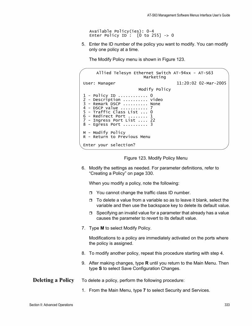
AT-S63 Management Software Menus Interface User’s Guide
Available Policy(ies): 0-4Enter Policy ID : [0 to 255] -> 0
5. Enter the ID number of the policy you want to modify. You can modify only one policy at a time.
The Modify Policy menu is shown in Figure 123.
Figure 123. Modify Policy Menu
6. Modify the settings as needed. For parameter definitions, refer to “Creating a Policy” on page 330.
When you modify a policy, note the following:
You cannot change the traffic class ID number.To delete a value from a variable so as to leave it blank, select the variable and then use the backspace key to delete its default value.Specifying an invalid value for a parameter that already has a value causes the parameter to revert to its default value.
7. Type M to select Modify Policy.
Modifications to a policy are immediately activated on the ports where the policy is assigned.
8. To modify another policy, repeat this procedure starting with step 4.
9. After making changes, type R until you return to the Main Menu. Then type S to select Save Configuration Changes.
Deleting a Policy To delete a policy, perform the following procedure:
1. From the Main Menu, type 7 to select Security and Services.
Allied Telesyn Ethernet Switch AT-94xx - AT-S63Marketing
User: Manager 11:20:02 02-Mar-2005
Modify Policy
1 - Policy ID ............ 02 - Description .......... video3 - Remark DSCP .......... None4 - DSCP value ........... 75 - Traffic Class List ... 06 - Redirect Port ........ 17 - Ingress Port List .... 228 - Egress Port .......... 3
M - Modify PolicyR - Return to Previous Menu
Enter your selection?
Section II: Advanced Operations 333
Chapter 16: Quality of Service
The Security and Services menu is shown in Figure 82 on page 259.
2. From the Security and Services menu, type 6 to select Quality of Service.
The Quality of Service (QoS) menu is shown in Figure 108 on page 313.
3. From the Quality of Service (QoS) menu, type 3 to select Policy Configuration.
The Policy Configuration menu is shown in Figure 121 on page 330.
4. From the Policy Configuration menu, type, type 3 to select Destroy Policy.
The following prompt is displayed:
Available Policy(ies): 0-4Enter Policy ID : [0 to 255] -> 0
5. Enter the ID number of the policy you want to delete. You can delete only one policy at a time.
6. Type D to delete the policy.
The policy is deleted from the switch.
7. To delete another policy, repeat this procedure starting with step 4.
8. After making changes, type R until you return to the Main Menu. Then type S to select Save Configuration Changes.
DisplayingPolicies
To display policies, perform the following procedure:
1. From the Main Menu, type 7 to select Security and Services.
The Security and Services menu is shown in Figure 82 on page 259.
2. From the Security and Services menu, type 6 to select Quality of Service.
The Quality of Service (QoS) menu is shown in Figure 108 on page 313.
3. From the Quality of Service (QoS) menu, type 3 to select Policy Configuration.
The Policy Configuration menu is shown in Figure 121 on page 330.
4. From the Policy Configuration menu, type 4 to select Show Policies.
334 Section II: Advanced Operations
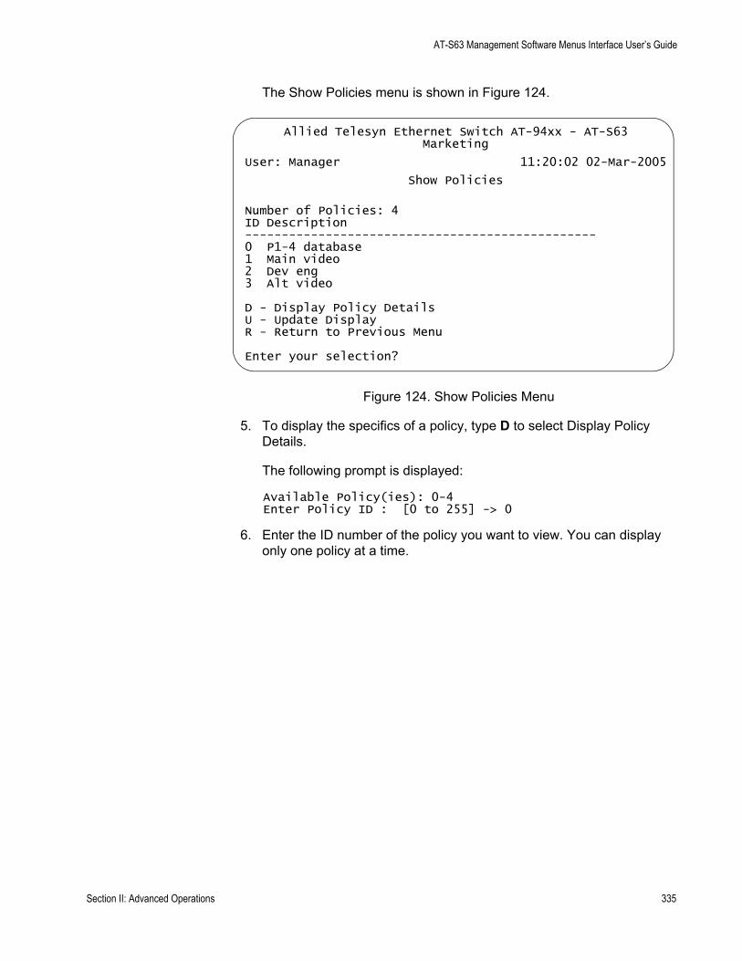
AT-S63 Management Software Menus Interface User’s Guide
The Show Policies menu is shown in Figure 124.
Figure 124. Show Policies Menu
5. To display the specifics of a policy, type D to select Display Policy Details.
The following prompt is displayed:
Available Policy(ies): 0-4Enter Policy ID : [0 to 255] -> 0
6. Enter the ID number of the policy you want to view. You can display only one policy at a time.
Allied Telesyn Ethernet Switch AT-94xx - AT-S63Marketing
User: Manager 11:20:02 02-Mar-2005
Show Policies
Number of Policies: 4ID Description------------------------------------------------0 P1-4 database1 Main video2 Dev eng3 Alt video
D - Display Policy DetailsU - Update DisplayR - Return to Previous Menu
Enter your selection?
Section II: Advanced Operations 335
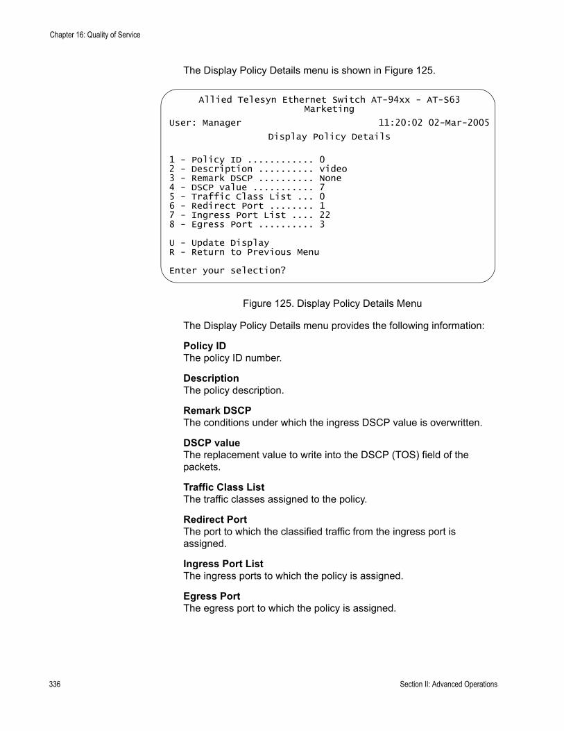
Chapter 16: Quality of Service
The Display Policy Details menu is shown in Figure 125.
Figure 125. Display Policy Details Menu
The Display Policy Details menu provides the following information:
Policy IDThe policy ID number.
DescriptionThe policy description.
Remark DSCPThe conditions under which the ingress DSCP value is overwritten.
DSCP valueThe replacement value to write into the DSCP (TOS) field of the packets.
Traffic Class ListThe traffic classes assigned to the policy.
Redirect PortThe port to which the classified traffic from the ingress port is assigned.
Ingress Port ListThe ingress ports to which the policy is assigned.
Egress PortThe egress port to which the policy is assigned.
Allied Telesyn Ethernet Switch AT-94xx - AT-S63Marketing
User: Manager 11:20:02 02-Mar-2005
Display Policy Details
1 - Policy ID ............ 02 - Description .......... video3 - Remark DSCP .......... None4 - DSCP value ........... 75 - Traffic Class List ... 06 - Redirect Port ........ 17 - Ingress Port List .... 228 - Egress Port .......... 3
U - Update DisplayR - Return to Previous Menu
Enter your selection?
336 Section II: Advanced Operations

Chapter 17
Class of Service
This chapter contains the procedures for configuring Class of Service (CoS). Sections in the chapter include:
“Class of Service Overview” on page 338“Configuring CoS” on page 343“Mapping CoS Priorities to Egress Queues” on page 346“Configuring Egress Scheduling” on page 348“Displaying Port CoS Priorities” on page 350
Section II: Advanced Operations 337
Chapter 17: Class of Service
Class of Service Overview
When a port on an Ethernet switch becomes oversubscribed—its egress queues contain more packets than the port can handle in a timely manner—the port may be forced to delay the transmission of some packets, resulting in the delay of packets reaching their destinations. A port may be forced to delay transmission of packets while it handles other traffic, and, in some situations, some packets destined to be forwarded to an oversubscribed port from other switch ports may be discarded.
Minor delays are often of no consequence to a network or its performance. But there are applications, referred to as delay or time sensitive applications, that can be impacted by packet delays. Voice transmission and video conferencing are two examples. If packets carrying data for either of these are delayed from reaching their destination, the audio or video quality may suffer.
This is where CoS is of value. It allows you to manage the flow of traffic through a switch by having the switch ports give higher priority to some packets, such as delay sensitive traffic, over other packets. This is referred to as prioritizing traffic.
CoS applies primarily to tagged packets. A tagged packet, as explained in “Tagged VLAN Overview” on page 556, contains information within it that specifies the VLAN to which the packet belongs.
A tagged packet can also contain a priority level. This priority level is used by network switches and other networking devices to know how important (delay sensitive) that packet is compared to other packets. Packets of a high priority are typically handled before packets of a low priority.
CoS, as defined in the IEEE 802.1p standard, has eight levels of priority. The priorities are 0 to 7, with 0 the lowest priority and 7 the highest.
When a tagged packet is received on a port on the switch, it is examined by the AT-S63 software for its priority. The switch software uses the priority to determine which egress priority queue the packet should be directed to on the egress port.
Each switch port has four egress queues, labeled Q0, Q1, Q2, and Q3. Q0 is the lowest priority queue and Q3 is the highest. A packet in a high priority egress queue is typically transmitted out a port sooner than a packet in a low priority queue.
Table 6 lists the mappings between the eight CoS priority levels and the
338 Section II: Advanced Operations

AT-S63 Management Software Menus Interface User’s Guide
four egress queues of a switch port.
For example, if a tagged packet with a priority level of 3 entered a port on the switch, the switch would store the packet in Q1 queue on the egress port.
Note that priority 0 is mapped to CoS queue 1 instead of CoS queue 0 because tagged traffic that has never been prioritized has a VLAN tag User Priority of 0. If priority 0 was mapped to CoS queue 0, this default traffic goes to the lowest queue, which is probably undesirable. This mapping also makes it possible to give some traffic a lower priority than the default traffic.
You can change these mappings. For example, you might decide that packets with a priority of 5 need to be handled by egress queue Q3 and packets with a priority of 2 should be handled in Q1. The result is shown in Table 7..
Table 6. Default Mappings of IEEE 802.1p Priority Levels to Priority Queues
IEEE 802.1p Priority Level Port Priority Queue
0 Q1
1 Q0
2 Q0
3 Q1
4 Q2
5 Q2
6 Q3
7 Q3
Table 7. Customized Mappings of IEEE 802.1p Priority Levels to Priority Queues
IEEE 802.1p Priority Level Port Priority Queue
0 Q1
1 Q0
2 Q1
3 Q1
4 Q2
Section II: Advanced Operations 339

Chapter 17: Class of Service
The procedure for changing the default mappings is found in “Mapping CoS Priorities to Egress Queues” on page 346. Note that because all ports must use the same priority-to-egress queue mappings, these mappings are applied at the switch level. They cannot be set on a per-port basis.
You can configure a port to completely ignore the priority levels in its tagged packets and store all the packets in the same egress queue. For instance, perhaps you decide that all tagged packets received on port 4 should be stored in an egress port’s Q3 egress queue, regardless of the priority level in the packets themselves. The procedure for overriding priority levels is explained in “Configuring CoS” on page 343.
CoS relates primarily to tagged packets rather than untagged packets because untagged packets do not contain a priority level. By default, all untagged packets are placed in a port’s Q0 egress queue, the queue with the lowest priority. But you can override this and instruct a port’s untagged frames to be stored in a higher priority queue. The procedure for this is also explained in “Configuring CoS” on page 343.
One last thing to note is that the AT-S63 software does not change the priority level in a tagged packet. The packet leaves the switch with the same priority it had when it entered. This is true even if you change the default priority-to-egress queue mappings.
Scheduling A switch port needs a mechanism for knowing the order in which it should handle the packets in its four egress queues. For example, if all the queues contain packets, should the port transmit all packets from Q3, the highest priority queue, before moving on to the other queues, or should it instead just do a few packets from each queue and, if so, how many?
This control mechanism is called scheduling. Scheduling determines the order in which a port handles the packets in its egress queues. The AT-S63 software has two types of scheduling:
Strict priorityWeighted round robin priority
5 Q3
6 Q3
7 Q3
Table 7. Customized Mappings of IEEE 802.1p Priority Levels to Priority Queues
IEEE 802.1p Priority Level Port Priority Queue
340 Section II: Advanced Operations
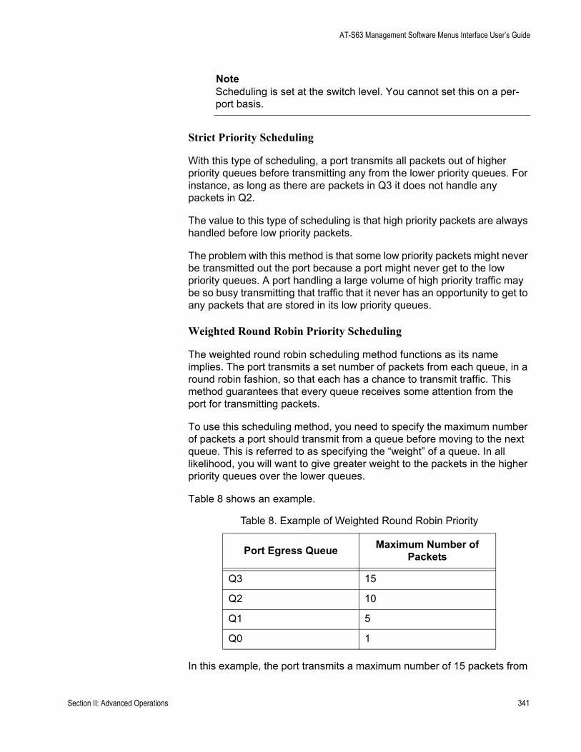
AT-S63 Management Software Menus Interface User’s Guide
NoteScheduling is set at the switch level. You cannot set this on a per-port basis.
Strict Priority Scheduling
With this type of scheduling, a port transmits all packets out of higher priority queues before transmitting any from the lower priority queues. For instance, as long as there are packets in Q3 it does not handle any packets in Q2.
The value to this type of scheduling is that high priority packets are always handled before low priority packets.
The problem with this method is that some low priority packets might never be transmitted out the port because a port might never get to the low priority queues. A port handling a large volume of high priority traffic may be so busy transmitting that traffic that it never has an opportunity to get to any packets that are stored in its low priority queues.
Weighted Round Robin Priority Scheduling
The weighted round robin scheduling method functions as its name implies. The port transmits a set number of packets from each queue, in a round robin fashion, so that each has a chance to transmit traffic. This method guarantees that every queue receives some attention from the port for transmitting packets.
To use this scheduling method, you need to specify the maximum number of packets a port should transmit from a queue before moving to the next queue. This is referred to as specifying the “weight” of a queue. In all likelihood, you will want to give greater weight to the packets in the higher priority queues over the lower queues.
Table 8 shows an example.
In this example, the port transmits a maximum number of 15 packets from
Table 8. Example of Weighted Round Robin Priority
Port Egress Queue Maximum Number of Packets
Q3 15
Q2 10
Q1 5
Q0 1
Section II: Advanced Operations 341

Chapter 17: Class of Service
Q3 before moving to Q2, from which it transmits up to 10 packets, and so forth.
342 Section II: Advanced Operations
AT-S63 Management Software Menus Interface User’s Guide
Configuring CoS
As explained in “Class of Service Overview” on page 338, a tagged packet received on a port is placed it into one of four priority queues on the egress port according to the switch’s mapping of 802.1p priority levels to egress priority queues. The default mappings are shown in Table 6 on page 339.
However, you can override the mappings at the port level so that all tagged packets are placed into a specific egress priority queue regardless of the priority level in the packets themselves. Note that this determination is made when a packet is received on the ingress port and before the frame is forwarded to the egress port. Consequently, you need to configure this feature on the ingress port.
For example, when you configure a switch port so that all ingress tagged frames are handled by the egress priority queue Q2, all tagged frames received on the port are directed to the Q2 priority egress queue on the egress ports.
You can also use CoS to control which priority queue handles untagged frames that ingress a port. By default, untagged frames (that is, frames without VLAN or priority level information) are automatically assigned to Q0, the lowest priority queue. But you can configure CoS on a port so that all untagged frames received on the port are directed to one of the other queues.
To configure CoS for a port, perform the following procedure:
1. From the Main Menu, type 7 to select Security and Services.
The Security and Services menu is shown in Figure 82 on page 259.
NoteItems 7, 8, and 9 are not available in all versions of the AT-S63 management software. Contact your sales representative to determine if these features are available for your locale.
2. From the Security and Services menu, type 5 to select Class of Service (CoS).
Section II: Advanced Operations 343
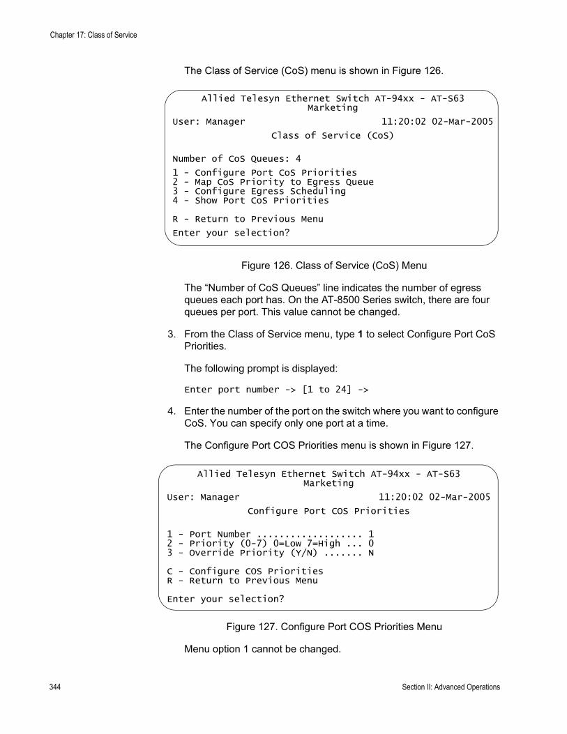
Chapter 17: Class of Service
The Class of Service (CoS) menu is shown in Figure 126.
Figure 126. Class of Service (CoS) Menu
The “Number of CoS Queues” line indicates the number of egress queues each port has. On the AT-8500 Series switch, there are four queues per port. This value cannot be changed.
3. From the Class of Service menu, type 1 to select Configure Port CoS Priorities.
The following prompt is displayed:
Enter port number -> [1 to 24] ->
4. Enter the number of the port on the switch where you want to configure CoS. You can specify only one port at a time.
The Configure Port COS Priorities menu is shown in Figure 127.
Figure 127. Configure Port COS Priorities Menu
Menu option 1 cannot be changed.
Allied Telesyn Ethernet Switch AT-94xx - AT-S63Marketing
User: Manager 11:20:02 02-Mar-2005
Class of Service (CoS)
Number of CoS Queues: 4
1 - Configure Port CoS Priorities2 - Map CoS Priority to Egress Queue3 - Configure Egress Scheduling4 - Show Port CoS Priorities
R - Return to Previous Menu
Enter your selection?
Allied Telesyn Ethernet Switch AT-94xx - AT-S63Marketing
User: Manager 11:20:02 02-Mar-2005
Configure Port COS Priorities
1 - Port Number ................... 12 - Priority (0-7) 0=Low 7=High ... 03 - Override Priority (Y/N) ....... N
C - Configure COS PrioritiesR - Return to Previous Menu
Enter your selection?
344 Section II: Advanced Operations

AT-S63 Management Software Menus Interface User’s Guide
5. Type 2 to select Priority (0 - 7). The following prompt is displayed:
Enter new value -> [0 to 7]
6. Enter a value from 1 to 7 that corresponds to the egress queue where you want all untagged frames received on the port to be stored. For example, if you want all ingress untagged packets received on the port stored in egress queue Q2, enter 4 or 5. The default is 0, which corresponds to Q0. (If you perform Step 6 and override the priority level in tagged packets, this queue will also be used to store all tagged packets.) The default values are listed in Table 6.
7. If you are configuring a tagged port and you want the switch to ignore the priority tag in ingress tagged frames, type 3 to select Override Priority and type Y.
All ingress tagged frames are directed to the queue specified in Step 6.
NoteThe tagged information in a frame is not changed as the frame traverses the switch. A tagged frame leaves a switch with the same priority level that it had when it entered.
The default for this parameter is No, meaning that the priority level of tagged frames is determined by the priority level specified in the frame itself.
8. Type C to select Configure Port COS Priorities.
A change to a port CoS setting is immediately activated on the port.
9. After making changes, type R until you return to the Main Menu. Then type S to select Save Configuration Changes.
Section II: Advanced Operations 345
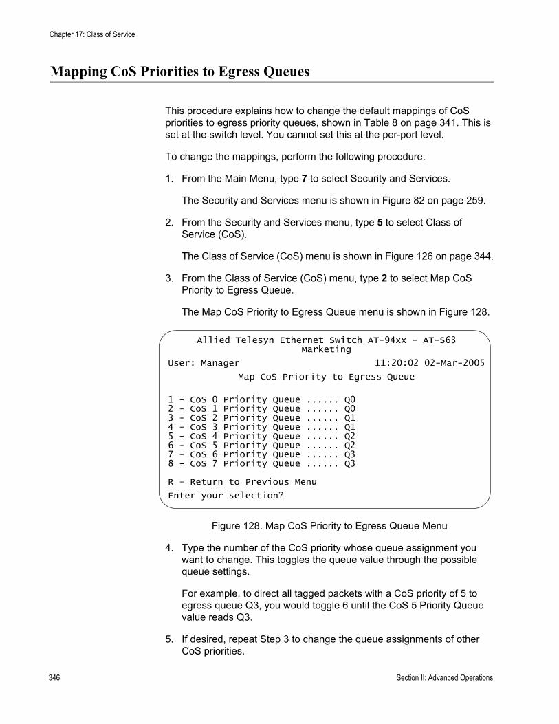
Chapter 17: Class of Service
Mapping CoS Priorities to Egress Queues
This procedure explains how to change the default mappings of CoS priorities to egress priority queues, shown in Table 8 on page 341. This is set at the switch level. You cannot set this at the per-port level.
To change the mappings, perform the following procedure.
1. From the Main Menu, type 7 to select Security and Services.
The Security and Services menu is shown in Figure 82 on page 259.
2. From the Security and Services menu, type 5 to select Class of Service (CoS).
The Class of Service (CoS) menu is shown in Figure 126 on page 344.
3. From the Class of Service (CoS) menu, type 2 to select Map CoS Priority to Egress Queue.
The Map CoS Priority to Egress Queue menu is shown in Figure 128.
Figure 128. Map CoS Priority to Egress Queue Menu
4. Type the number of the CoS priority whose queue assignment you want to change. This toggles the queue value through the possible queue settings.
For example, to direct all tagged packets with a CoS priority of 5 to egress queue Q3, you would toggle 6 until the CoS 5 Priority Queue value reads Q3.
5. If desired, repeat Step 3 to change the queue assignments of other CoS priorities.
Allied Telesyn Ethernet Switch AT-94xx - AT-S63Marketing
User: Manager 11:20:02 02-Mar-2005
Map CoS Priority to Egress Queue
1 - CoS 0 Priority Queue ...... Q02 - CoS 1 Priority Queue ...... Q03 - CoS 2 Priority Queue ...... Q14 - CoS 3 Priority Queue ...... Q15 - CoS 4 Priority Queue ...... Q26 - CoS 5 Priority Queue ...... Q27 - CoS 6 Priority Queue ...... Q38 - CoS 7 Priority Queue ...... Q3
R - Return to Previous Menu
Enter your selection?
346 Section II: Advanced Operations

AT-S63 Management Software Menus Interface User’s Guide
6. After making changes, type R until you return to the Main Menu. Then type S to select Save Configuration Changes.
Section II: Advanced Operations 347
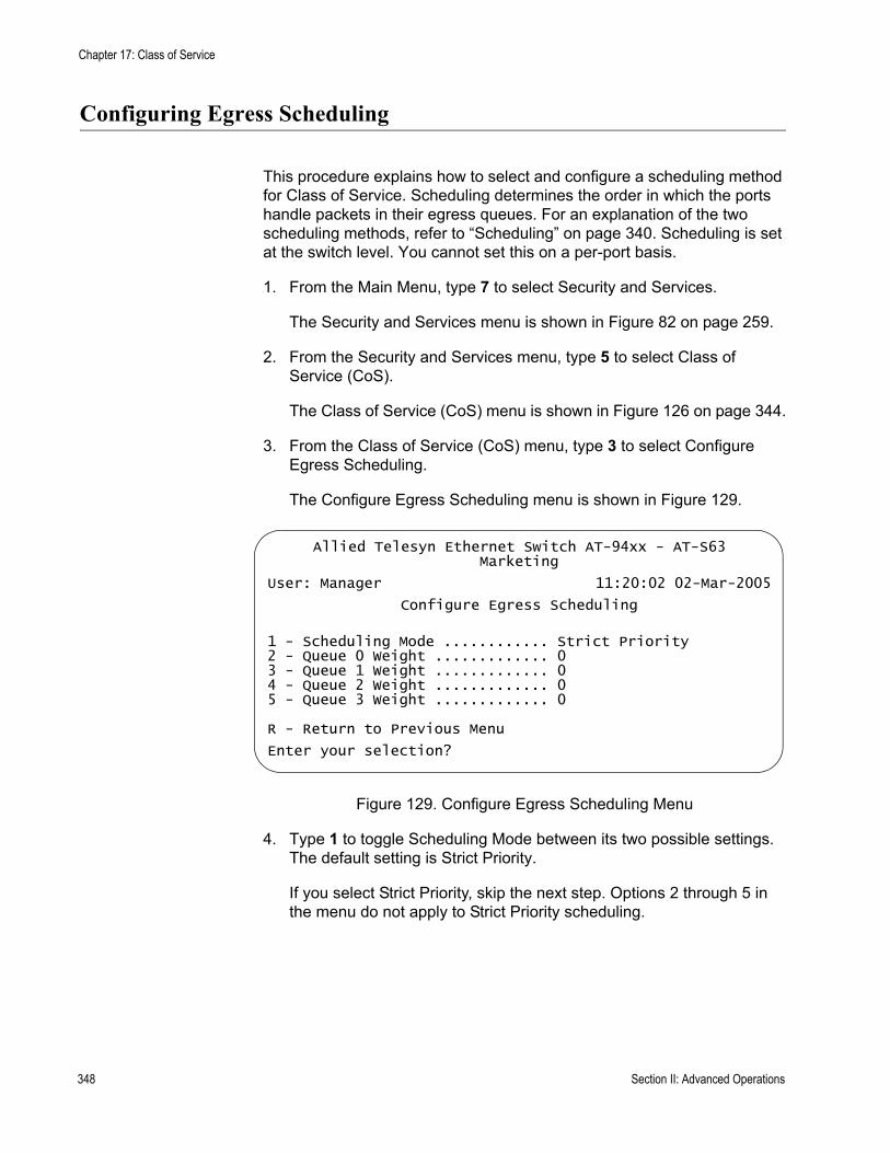
Chapter 17: Class of Service
Configuring Egress Scheduling
This procedure explains how to select and configure a scheduling method for Class of Service. Scheduling determines the order in which the ports handle packets in their egress queues. For an explanation of the two scheduling methods, refer to “Scheduling” on page 340. Scheduling is set at the switch level. You cannot set this on a per-port basis.
1. From the Main Menu, type 7 to select Security and Services.
The Security and Services menu is shown in Figure 82 on page 259.
2. From the Security and Services menu, type 5 to select Class of Service (CoS).
The Class of Service (CoS) menu is shown in Figure 126 on page 344.
3. From the Class of Service (CoS) menu, type 3 to select Configure Egress Scheduling.
The Configure Egress Scheduling menu is shown in Figure 129.
Figure 129. Configure Egress Scheduling Menu
4. Type 1 to toggle Scheduling Mode between its two possible settings. The default setting is Strict Priority.
If you select Strict Priority, skip the next step. Options 2 through 5 in the menu do not apply to Strict Priority scheduling.
Allied Telesyn Ethernet Switch AT-94xx - AT-S63Marketing
User: Manager 11:20:02 02-Mar-2005
Configure Egress Scheduling
1 - Scheduling Mode ............ Strict Priority2 - Queue 0 Weight ............. 03 - Queue 1 Weight ............. 04 - Queue 2 Weight ............. 05 - Queue 3 Weight ............. 0
R - Return to Previous Menu
Enter your selection?
348 Section II: Advanced Operations

AT-S63 Management Software Menus Interface User’s Guide
5. If you select Weighted Round Robin Priority as the scheduling method, select menu options 2 through 5 and specify the maximum number of packets you want a port to transmit from each queue before it moves to the next queue. The range is 0 to 255. For an example, refer to Table 8 on page 341. The default value of 1 for each queue gives all egress queues the same weight.
6. Return to the Main Menu and type S to select Save Configuration Changes.
Section II: Advanced Operations 349
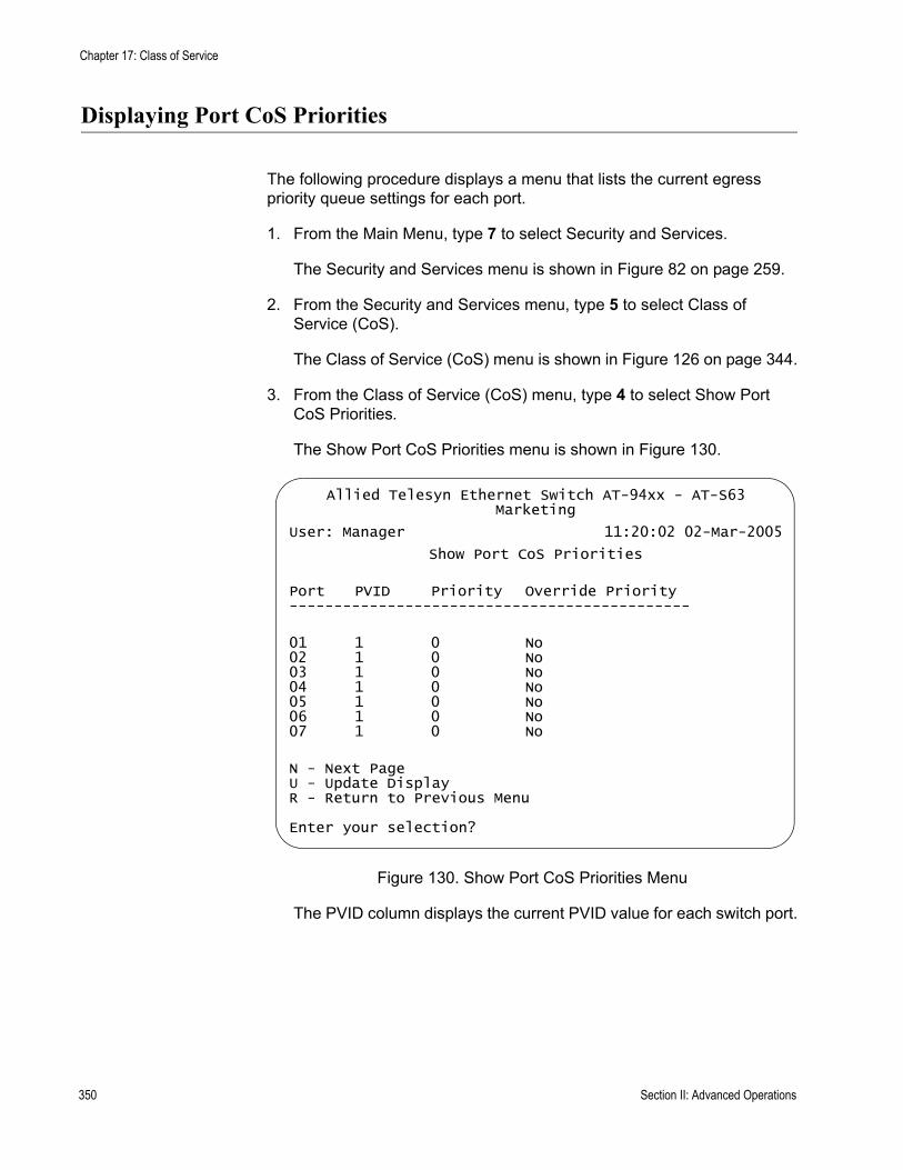
Chapter 17: Class of Service
Displaying Port CoS Priorities
The following procedure displays a menu that lists the current egress priority queue settings for each port.
1. From the Main Menu, type 7 to select Security and Services.
The Security and Services menu is shown in Figure 82 on page 259.
2. From the Security and Services menu, type 5 to select Class of Service (CoS).
The Class of Service (CoS) menu is shown in Figure 126 on page 344.
3. From the Class of Service (CoS) menu, type 4 to select Show Port CoS Priorities.
The Show Port CoS Priorities menu is shown in Figure 130.
Figure 130. Show Port CoS Priorities Menu
The PVID column displays the current PVID value for each switch port.
Allied Telesyn Ethernet Switch AT-94xx - AT-S63Marketing
User: Manager 11:20:02 02-Mar-2005
Show Port CoS Priorities
Port PVID Priority Override Priority---------------------------------------------
01 1 0 No02 1 0 No03 1 0 No04 1 0 No05 1 0 No06 1 0 No07 1 0 No
N - Next PageU - Update DisplayR - Return to Previous Menu
Enter your selection?
350 Section II: Advanced Operations
Chapter 18
IGMP Snooping
This chapter explains how to activate and configure the Internet Group Management Protocol (IGMP) snooping feature on the switch. Sections in the chapter include:
“IGMP Snooping Overview” on page 352“Configuring IGMP Snooping” on page 354“Enabling or Disabling IGMP Snooping” on page 357“Displaying a List of Host Nodes” on page 358“Displaying a List of Multicast Routers” on page 360
Section II: Advanced Operations 351
Chapter 18: IGMP Snooping
IGMP Snooping Overview
The IGMP protocol enables routers to create lists of nodes that are members of multicast groups. (A multicast group is a group of end nodes that want to receive multicast packets from a multicast application.) The router creates a multicast membership list by periodically sending out queries to the local area networks connected to its ports.
A node wanting to become a member of a multicast group responds to a query by sending a report. A report indicates an end node’s desire to become a member of a multicast group. Nodes that join a multicast group are referred to as host nodes. After becoming a member of a multicast group, a host node must continue to periodically issue reports to remain a member.
After the router has received a report from a host node, it notes the multicast group that the host node wants to join and the port on the router where the node is located. Any multicast packets belonging to that multicast group are then forwarded by the router out the port. If a particular port on the router has no nodes that want to be members of multicast groups, the router does not send multicast packets out the port. This improves network performance by restricting multicast packets only to router ports where host nodes are located.
There are three versions of IGMP — versions 1, 2, and 3. One of the differences between the versions is how a host node signals that it no longer wants to be a member of a multicast group. In version 1 it stops sending reports. If a router does not receive a report from a host node after a predefined length of time, referred to as a time-out value, it assumes that the host node no longer wants to receive multicast frames, and removes it from the membership list of the multicast group.
In version 2 a host node exits from a multicast group by sending a leave request. After receiving a leave request from a host node, the router removes the node from appropriate membership list. The router also stops sending multicast packets out the port to which the node is connected if it determines there are no further host nodes on the port.
Version 3 adds the ability of host nodes to join or leave specific sources in a multicast group through the use of Group-Source report and Group-Source leave messages.
The IGMP snooping feature on the AT-9400 Series switch supports all three versions of IGMP. It enables the switch to monitor the flow of queries from a router and reports and leave messages from host nodes to build its own multicast membership lists. It uses the lists to forward multicast packets only to switch ports where there are host nodes that are members of multicast groups. This improves switch performance and network security by restricting the flow of multicast packets only to those switch
352 Section II: Advanced Operations

AT-S63 Management Software Menus Interface User’s Guide
ports connected to host nodes.
Without IGMP snooping a switch would have to flood multicast packets out all of its ports, except the port on which it received the packet. Such flooding of packets can negatively impact switch and network performance.
The AT-9400 Series switch maintains its list of multicast groups through an adjustable timeout value, which controls how frequently it expects to see reports from end nodes that want to remain members of multicast groups, and by processing leave requests.
NoteBy default, IGMP snooping is disabled on the switch.
Section II: Advanced Operations 353
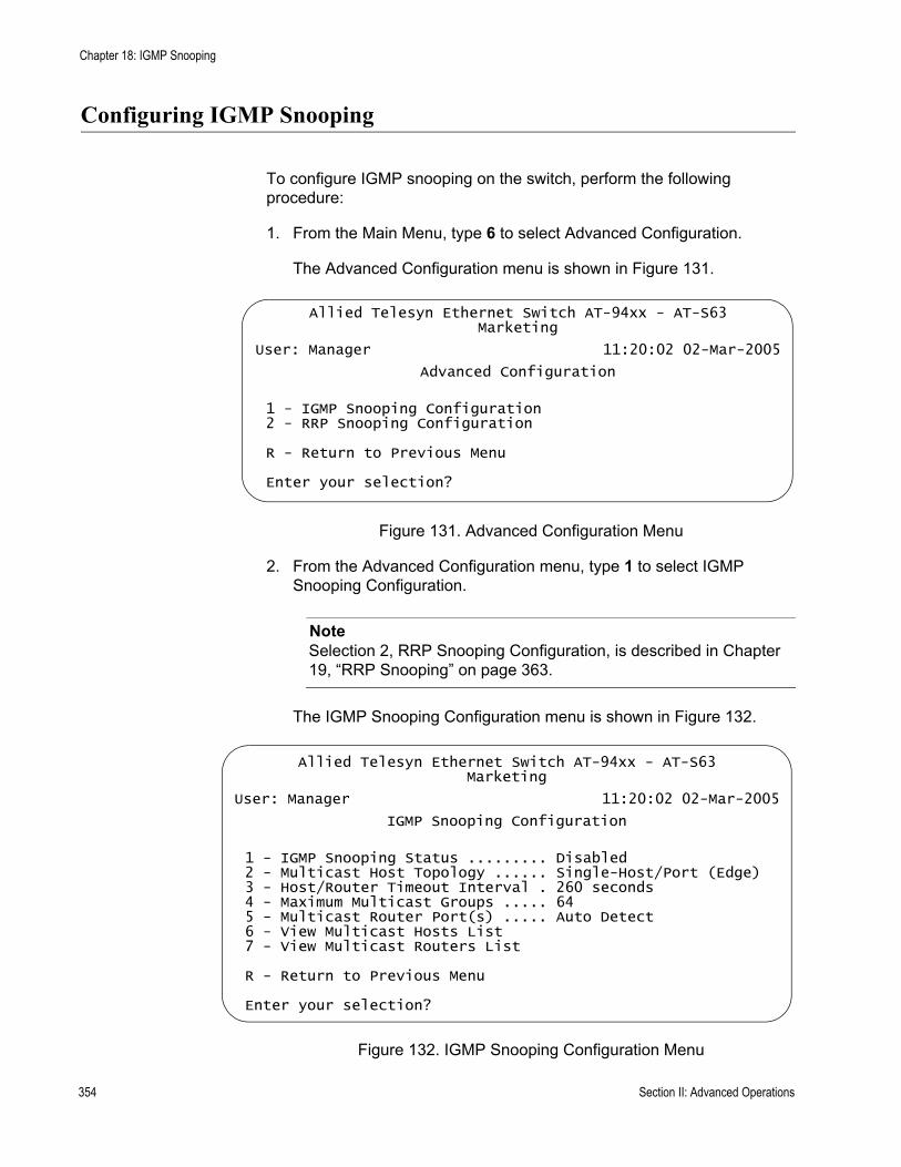
Chapter 18: IGMP Snooping
Configuring IGMP Snooping
To configure IGMP snooping on the switch, perform the following procedure:
1. From the Main Menu, type 6 to select Advanced Configuration.
The Advanced Configuration menu is shown in Figure 131.
Figure 131. Advanced Configuration Menu
2. From the Advanced Configuration menu, type 1 to select IGMP Snooping Configuration.
NoteSelection 2, RRP Snooping Configuration, is described in Chapter 19, “RRP Snooping” on page 363.
The IGMP Snooping Configuration menu is shown in Figure 132.
Figure 132. IGMP Snooping Configuration Menu
Allied Telesyn Ethernet Switch AT-94xx - AT-S63Marketing
User: Manager 11:20:02 02-Mar-2005
Advanced Configuration
1 - IGMP Snooping Configuration2 - RRP Snooping Configuration
R - Return to Previous Menu
Enter your selection?
Allied Telesyn Ethernet Switch AT-94xx - AT-S63Marketing
User: Manager 11:20:02 02-Mar-2005
IGMP Snooping Configuration
1 - IGMP Snooping Status ......... Disabled2 - Multicast Host Topology ...... Single-Host/Port (Edge)3 - Host/Router Timeout Interval . 260 seconds4 - Maximum Multicast Groups ..... 645 - Multicast Router Port(s) ..... Auto Detect6 - View Multicast Hosts List7 - View Multicast Routers List
R - Return to Previous Menu
Enter your selection?
354 Section II: Advanced Operations

AT-S63 Management Software Menus Interface User’s Guide
3. Adjust the following parameters as necessary:
1 - IGMP Snooping StatusEnables or disables IGMP snooping on the switch. After you choose this selection, type E to enable to D to disable this feature.
2 - Multicast Host TopologyDefines whether there is only one host node per switch port or multiple host nodes per port. The possible settings are:
Single-Host/Port (Edge)The Single-Host/Port setting is appropriate when there is only one host node connected to each port on the switch. This setting causes the switch to immediately stop sending multicast packets out a switch port when a host node signals its desire to leave a multicast group by sending a leave request or when the host node stops sending reports. The switch responds by immediately ceasing the transmission of additional multicast packets out the port where the host node is connected.
Multiple Host/Ports (Intermediate)The Multi-Host setting is appropriate if there is more than one host node connected to a switch port, such as when a port is connected to an Ethernet hub to which multiple host nodes are connected. With this setting selected the switch continues sending multicast packets out a port even after it receives a leave request from a host node on the port. This ensures that the remaining active host nodes on the port continue to receive the multicast packets. Only after all the host nodes connected to a switch port have transmitted leave requests or have timed out does the switch stop sending multicast packets out the port.
If a switch has a mixture of host nodes, that is, some connected directly to the switch and others through an Ethernet hub, you should select the Multi-Host Port (Intermediate) selection.
3 - Host/Router Timeout IntervalSpecifies the time period in seconds at which the switch determines that a host node has become inactive. An inactive host node is a node that has not sent an IGMP report during the specified time interval. The range is from 0 second to 86,400 seconds (24 hours). The default is 260 seconds. If you set the timeout to zero (0), the timer never times out, and the timeout interval is essentially disabled.
This parameter also specifies the time interval used by the switch in determining whether a multicast router is still active. The switch makes the determination by watching for queries from the router. If the switch does not detect any queries from a multicast router during the specified time interval, it assumes that the router is no longer active on the port.
When you select a value for this parameter, it is important to note that the value you enter actually defines the approximate mid-point of a
Section II: Advanced Operations 355

Chapter 18: IGMP Snooping
range within which a timeout can occur. Consequently, an actual timeout may occur earlier or later than the value that you enter. The range is from 0.7 to 1.4 of your value. For example, if you leave this parameter set to the default 260 seconds, a timeout can occur from 182 seconds to 364 seconds. Also, the last 10 seconds are not aged out regardless of the interval you set. You may need to take this information into account when setting this parameter.
4 - Maximum Multicast GroupsThis parameter specifies the maximum number of multicast groups the switch learns. This parameter is useful with networks that contain a large number of multicast groups. You can use the parameter to prevent the switch’s MAC address table from filling up with multicast addresses, leaving no room for dynamic or static MAC addresses. The range is 1 to 255 groups. The default is 64 multicast groups.
5 - Multicast Router Port(s)Specifies the port on the switch to which a multicast router is detected. You can let the switch determine this automatically by selecting Auto Detect, or you can specify the port yourself by entering a port number. To select Auto Detect, enter “0” (zero) for this parameter. You can specify more than one port.
NoteA change to any parameter in this menu is immediately activated on the switch.
NoteSelection 6, View Multicast Hosts List, is described in ”Displaying a List of Host Nodes”, next. Selection 7, View Multicast Routers List, is described in “Displaying a List of Multicast Routers” on page 360.
4. After making changes, type R until you return to the Main Menu. Then type S to select Save Configuration Changes.
Your changes are activated immediately on the switch.
356 Section II: Advanced Operations
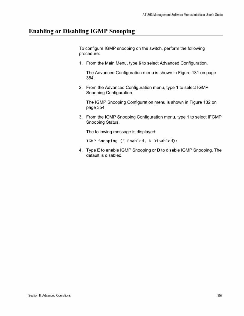
AT-S63 Management Software Menus Interface User’s Guide
Enabling or Disabling IGMP Snooping
To configure IGMP snooping on the switch, perform the following procedure:
1. From the Main Menu, type 6 to select Advanced Configuration.
The Advanced Configuration menu is shown in Figure 131 on page 354.
2. From the Advanced Configuration menu, type 1 to select IGMP Snooping Configuration.
The IGMP Snooping Configuration menu is shown in Figure 132 on page 354.
3. From the IGMP Snooping Configuration menu, type 1 to select IFGMP Snooping Status.
The following message is displayed:
IGMP Snooping (E-Enabled, D-Disabled):
4. Type E to enable IGMP Snooping or D to disable IGMP Snooping. The default is disabled.
Section II: Advanced Operations 357

Chapter 18: IGMP Snooping
Displaying a List of Host Nodes
You can use the AT-S63 management software to display a list of the multicast groups on a switch, as well as the host nodes. To display the list, perform the following procedure:
1. From the Main Menu, type 6 to select Advanced Configuration.
The Advanced Configuration menu is shown in Figure 131 on page 354
2. From the Advanced Configuration menu, type 1 to select IGMP Snooping Configuration.
The IGMP Snooping Configuration menu is shown in Figure 132 on page 354.
3. From the IGMP Snooping Configuration menu, type 6 to select View Multicast Hosts List.
The View Multicast Host List menu is shown in Figure 133.
Figure 133. View Multicast Hosts List Menu
The View Multicast Hosts List menu displays a table with the following columns of information:
Multicast GroupThe multicast address of the group.
Allied Telesyn Ethernet Switch AT-94xx - AT-S63Marketing
User: Manager 11:20:02 02-Mar-2005
View Multicast Hosts List
Number of Multicast Groups: 4VLAN Port/ IGMP Exp.
MulticastGroup ID TrunkID HostIP Ver Time------------------------------------------------------------01:00:5E:00:01:01 1 6 172.16.10.51 v2 2101:00:5E:7F:FF:FA 1 5 149.35.200.75 v2 11
149.35.200.65 v2 6501:00:5E:00:00:02 1 17 149.35.200.69 v2 3401:00:5E:00:00:09 1 14 172.16.10.51 v2 32
U - Update DisplayR - Return to Previous Menu
Enter your selection?
358 Section II: Advanced Operations
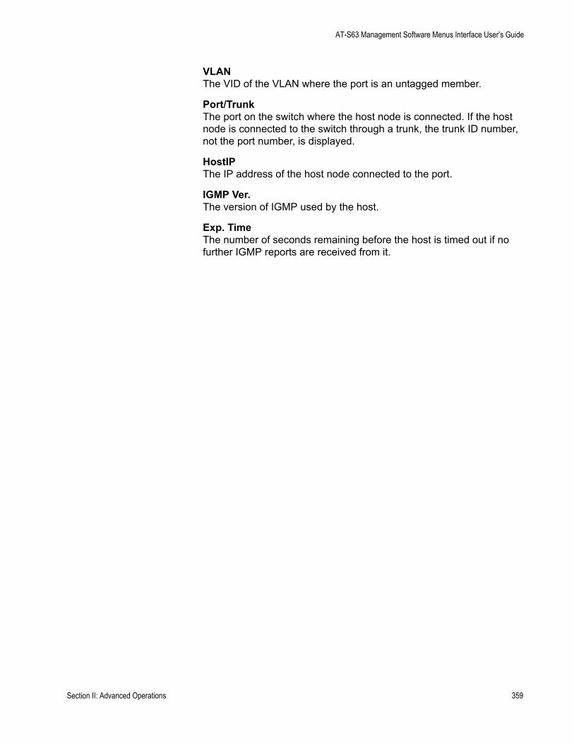
AT-S63 Management Software Menus Interface User’s Guide
VLANThe VID of the VLAN where the port is an untagged member.
Port/TrunkThe port on the switch where the host node is connected. If the host node is connected to the switch through a trunk, the trunk ID number, not the port number, is displayed.
HostIPThe IP address of the host node connected to the port.
IGMP Ver.The version of IGMP used by the host.
Exp. TimeThe number of seconds remaining before the host is timed out if no further IGMP reports are received from it.
Section II: Advanced Operations 359
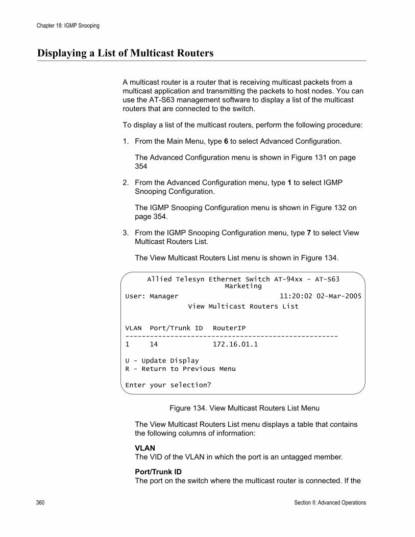
Chapter 18: IGMP Snooping
Displaying a List of Multicast Routers
A multicast router is a router that is receiving multicast packets from a multicast application and transmitting the packets to host nodes. You can use the AT-S63 management software to display a list of the multicast routers that are connected to the switch.
To display a list of the multicast routers, perform the following procedure:
1. From the Main Menu, type 6 to select Advanced Configuration.
The Advanced Configuration menu is shown in Figure 131 on page 354
2. From the Advanced Configuration menu, type 1 to select IGMP Snooping Configuration.
The IGMP Snooping Configuration menu is shown in Figure 132 on page 354.
3. From the IGMP Snooping Configuration menu, type 7 to select View Multicast Routers List.
The View Multicast Routers List menu is shown in Figure 134.
Figure 134. View Multicast Routers List Menu
The View Multicast Routers List menu displays a table that contains the following columns of information:
VLANThe VID of the VLAN in which the port is an untagged member.
Port/Trunk IDThe port on the switch where the multicast router is connected. If the
Allied Telesyn Ethernet Switch AT-94xx - AT-S63Marketing
User: Manager 11:20:02 02-Mar-2005
View Multicast Routers List
VLAN Port/Trunk ID RouterIP----------------------------------------------------1 14 172.16.01.1
U - Update DisplayR - Return to Previous Menu
Enter your selection?
360 Section II: Advanced Operations

AT-S63 Management Software Menus Interface User’s Guide
switch learned the router on a port trunk, the trunk ID number, not the port number, is displayed.
Router IPThe IP address of the multicast router.
Section II: Advanced Operations 361

Chapter 18: IGMP Snooping
362 Section II: Advanced Operations
Chapter 19
RRP Snooping
This chapter explains RRP snooping and contains the following sections:
“RRP Snooping Overview” on page 364“Enabling or Disabling RRP Snooping” on page 366
Section II: Advanced Operations 363
Chapter 19: RRP Snooping
RRP Snooping Overview
The Router Redundancy Protocol (RRP) allows multiple routers to share the same virtual IP address and MAC address. In network topologies where redundant router paths or links exist, the protocol enables routers, through an election process, to designate one as the master router. This router functions as the provider of the primary path between LAN segments. Slave routers function as backup paths in the event that the master router or primary path fails.
Because the master and slave routers are able to share the same virtual IP address and MAC address, a change in data paths does not necessitate adjusting the default gateways on the network nodes that employ the routers. When a slave router transitions to master, it uses the same IP address as the previous master router, making the transition transparent to network end nodes. In large networks, these transparent transitions can save the time and effort of manually reconfiguring default gateway addresses on large numbers of network nodes when a router pathway fails.
RRP snooping on the switch facilitates the transition to a new master router by minimizing the loss of traffic, and so reduces the impact the transition could have on your network traffic. RRP snooping monitors ingress RRP packets, determined by their source MAC address. Source MAC addresses considered by the AT-S63 management software as RRP packets are:
00:E0:2B:00:00:80-9F00:A0:D2EB:FF:0000:00:5E:00:01:00-FF
A port receiving an RRP packet is deemed by the switch as the master RRP port. The virtual MAC address of the router is entered as a dynamic address on the port. If the switch starts to receive RRP packets on another port, it assumes that a backup or slave router has made the transition into the role of the new master router.
The switch responds by deleting all dynamic MAC addresses from the MAC address table. As the switch relearns the addresses, the virtual MAC address of the new master router is learned on the new master RRP port, rather than the old port. Any packets received by the switch and destined for the router are forwarded to the new master router.
364 Section II: Advanced Operations
AT-S63 Management Software Menus Interface User’s Guide
The following guidelines apply to the RRP snooping feature:
The default setting for this feature is disabled.Activating the feature flushes all dynamic MAC addresses from the MAC address table.RRP snooping is supported on ports operating in the MAC security level of automatic. This feature is not supported on ports operating with a security level of limited, secured, or locked.RRP snooping is supported on port trunks.
Section II: Advanced Operations 365
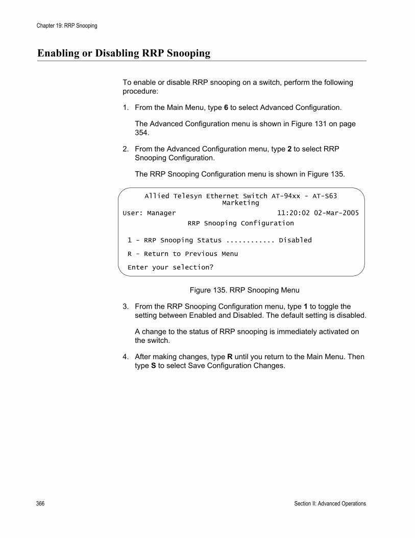
Chapter 19: RRP Snooping
Enabling or Disabling RRP Snooping
To enable or disable RRP snooping on a switch, perform the following procedure:
1. From the Main Menu, type 6 to select Advanced Configuration.
The Advanced Configuration menu is shown in Figure 131 on page 354.
2. From the Advanced Configuration menu, type 2 to select RRP Snooping Configuration.
The RRP Snooping Configuration menu is shown in Figure 135.
Figure 135. RRP Snooping Menu
3. From the RRP Snooping Configuration menu, type 1 to toggle the setting between Enabled and Disabled. The default setting is disabled.
A change to the status of RRP snooping is immediately activated on the switch.
4. After making changes, type R until you return to the Main Menu. Then type S to select Save Configuration Changes.
Allied Telesyn Ethernet Switch AT-94xx - AT-S63Marketing
User: Manager 11:20:02 02-Mar-2005
RRP Snooping Configuration
1 - RRP Snooping Status ............ Disabled
R - Return to Previous Menu
Enter your selection?
366 Section II: Advanced Operations

Section III
SNMPv3
The chapter in this section provides information and procedures for SNMPv3. The chapter is:
Chapter 20, ”SNMPv3” on page 369
Section III: SNMPv3 367

368 Section III: SNMPv3

Chapter 20
SNMPv3
This chapter provides a description of the AT-S63 implementation of the SNMPv3 protocol. In addition, the chapter contains procedures that allow you to create and modify SNMPv3 entities. The following sections are provided:
“SNMPv3 Overview” on page 370“Configuring SNMPv3 Entities” on page 379“Configuring the SNMPv3 User Table” on page 380“Configuring the SNMPv3 View Table” on page 390“Configuring the SNMPv3 Access Table” on page 399“Configuring the SNMPv3 SecurityToGroup Table” on page 414“Configuring the SNMPv3 Notify Table” on page 422“Configuring the SNMPv3 Target Address Table” on page 429“Configuring the SNMPv3 Target Parameters Table” on page 442“Configuring the SNMPv3 Community Table” on page 455“Displaying SNMPv3 Table Menus” on page 465
Section III: SNMPv3 369
Chapter 20: SNMPv3
SNMPv3 Overview
The SNMPv3 protocol builds on the existing SNMPv1 and SNMPv2c protocol implementation which is described in Chapter 4, “SNMPv1 and SNMPv2c” on page 75. In SNMPv3, User-based Security Model (USM) authentication is implemented along with encryption, allowing you to configure a secure SNMP environment.
In addition, SNMP terminology changes in the SNMPv3 protocol. In the SNMPv1 and SNMPv2c protocols, the terms agent and manager are used. An agent is an SNMP user while a manager is an SNMP host. In the SNMPv3 protocol, agents and managers are called entities. In any SNMPv3 communication, there is an authoritative entity and a non-authoritative entity. The authoritative entity checks the authenticity of the non-authoritative entity. And, the non-authoritative entity checks the authenticity of the authoritative entity.
With the SNMPv3 protocol, you create users, determine the protocol used for message authentication as well as determine if data transmitted between two SNMP entities is encrypted. In addition, you can restrict user privileges by determining the user’s view of the Management Information Bases (MIB). In this way, you restrict which MIBs the user can display and modify. In addition, you can restrict the types of messages, or traps, the user can send. (A trap is a type of SNMP message.)
After you have created a user, you define SNMPv3 message notification. This consists of determining where messages are sent and what types of messages can be sent. This configuration is similar to the SNMPv1 and SNMPv2c configuration because you configure IP addresses of trap receivers, or hosts. In addition, with the SNMPv3 implementation you decide what types of messages are sent.
NoteFor the SNMP RFCs supported by this release of the AT-S63 software, see “Using an SNMP Network Management Application” on page 31.
This section further describes the features of the SNMPv3 protocol. The following subsections are included:
“SNMPv3 Authentication Protocols” on page 371“SNMPv3 Privacy Protocol” on page 371“SNMPv3 MIB Views” on page 372“SNMPv3 Storage Types” on page 373“SNMPv3 Message Notification” on page 373“SNMPv3 Tables” on page 374
370 Section III: SNMPv3
AT-S63 Management Software Menus Interface User’s Guide
“SNMPv3 Configuration Example” on page 378
SNMPv3Authentication
Protocols
The SNMPv3 protocol supports two authentication protocols—HMAC-MD5-96 (MD5) and HMAC-SHA-96 (SHA). Both MD5 and SHA use an algorithm to generate a message digest. Each authentication protocol authenticates a user by checking the message digest. In addition, both protocols use keys to perform authentication. The keys for both protocols are generated locally using the Engine ID, a unique identifier that is assigned to the switch automatically, and the user password. You modify a key only by modifying the user password.
In addition, you have the option of assigning no user authentication. In this case, no authentication is performed for this user. You may want to make this configuration for someone with super-user capabilities.
NoteThe keys generated by the MD5 and SHA protocols are specific to the SNMPv3 protocol. They have no relation to the SSL and SSH keys for encryption.
SNMPv3 PrivacyProtocol
After you have configured an authentication protocol, you have the option of assigning a privacy protocol if you have the encrypted version of the AT-S63 software. In SNMPv3 protocol terminology, privacy is equivalent to encryption. Currently, the DES protocol is the only encryption protocol supported. The DES privacy protocol requires the authentication protocol to be configured as either MD5 or SHA.
If you assign a DES privacy protocol to a user, then you are also required to assign a privacy password. If you choose to not assign a privacy value, then SNMPv3 messages are sent in plain text format.
Section III: SNMPv3 371
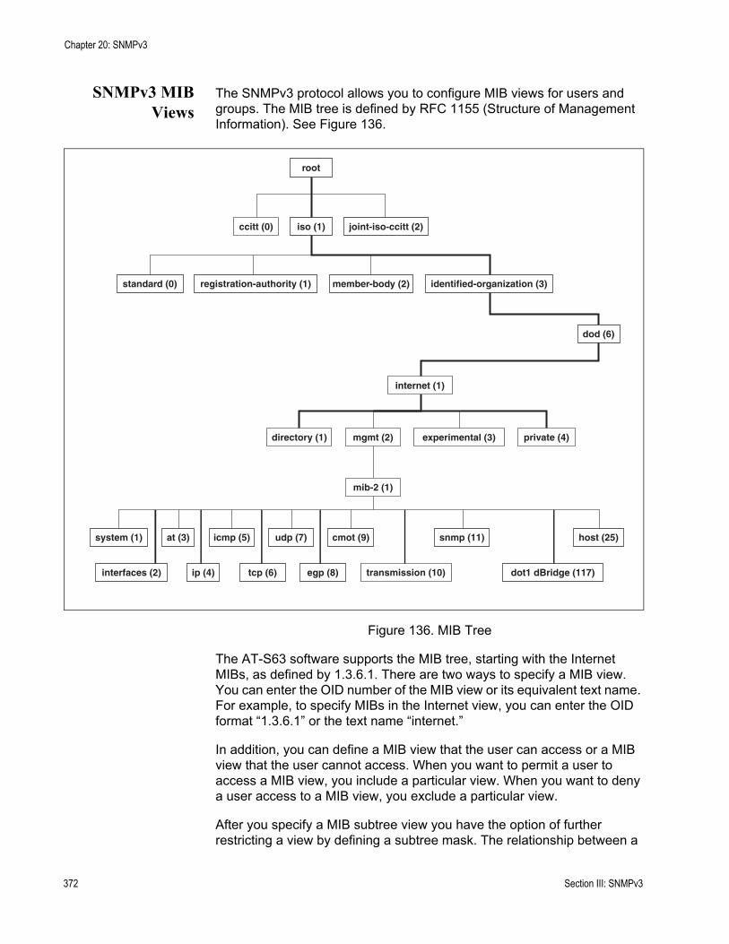
Chapter 20: SNMPv3
SNMPv3 MIBViews
The SNMPv3 protocol allows you to configure MIB views for users and groups. The MIB tree is defined by RFC 1155 (Structure of Management Information). See Figure 136.
Figure 136. MIB Tree
The AT-S63 software supports the MIB tree, starting with the Internet MIBs, as defined by 1.3.6.1. There are two ways to specify a MIB view. You can enter the OID number of the MIB view or its equivalent text name. For example, to specify MIBs in the Internet view, you can enter the OID format “1.3.6.1” or the text name “internet.”
In addition, you can define a MIB view that the user can access or a MIB view that the user cannot access. When you want to permit a user to access a MIB view, you include a particular view. When you want to deny a user access to a MIB view, you exclude a particular view.
After you specify a MIB subtree view you have the option of further restricting a view by defining a subtree mask. The relationship between a
root
ccitt (0) joint-iso-ccitt (2)
standard (0) registration-authority (1) member-body (2) identified-organization (3)
dod (6)
iso (1)
internet (1)
directory (1) mgmt (2) experimental (3) private (4)
mib-2 (1)
system (1) at (3) icmp (5) udp (7) cmot (9) snmp (11) host (25)
interfaces (2) ip (4) tcp (6) egp (8) transmission (10) dot1 dBridge (117)
372 Section III: SNMPv3

AT-S63 Management Software Menus Interface User’s Guide
MIB subtree view and a subtree mask is analogous to the relationship between an IP address and a subnet mask. The switch uses the subnet mask to determine which portion of an IP address represents the network address and which portion represents the node address. In a similar way, the subtree mask further refines the subtree view and enables you to restrict a MIB view to a specific row of the OID MIB table. You need a thorough understanding of the OID MIB table to define a subtree mask.
SNMPv3 StorageTypes
Each SNMPv3 table entry has its own storage type. You can choose between nonvolatile storage which allows you to save the table entry or volatile storage which does not allow you to save an entry. If you select the volatile storage type, when you power off the switch your SNMPv3 configuration is lost and cannot be recovered.
At each SNMPv3 menu, you are prompted to configure a storage type. You do not have to configure the same storage type value for each table entry.
SNMPv3 MessageNotification
When you generate an SNMPv3 message from the switch, there are three basic pieces of information included in the message:
The type of messageThe destination of the messageSNMP security information
To configure the type of message, you need to define if you are sending a Trap or Inform message. Basically, the switch expects a response to an Inform message and the switch does not expect a response to a Trap message. These two message types are defined in the SNMPv3 (RFC 2571-6).
To determine the destination of the message, you configure the IP address of the host. This configuration is similar to the SNMPv1 and SNMPv2c configuration.
The SNMP security information consists of information about the following:
UserView of the MIB TreeSecurity LevelSecurity ModelAuthentication LevelPrivacy ProtocolGroup
To configure the SNMP security information, you associate a user and its related information—View, Security Level, Security Model, Authentication
Section III: SNMPv3 373
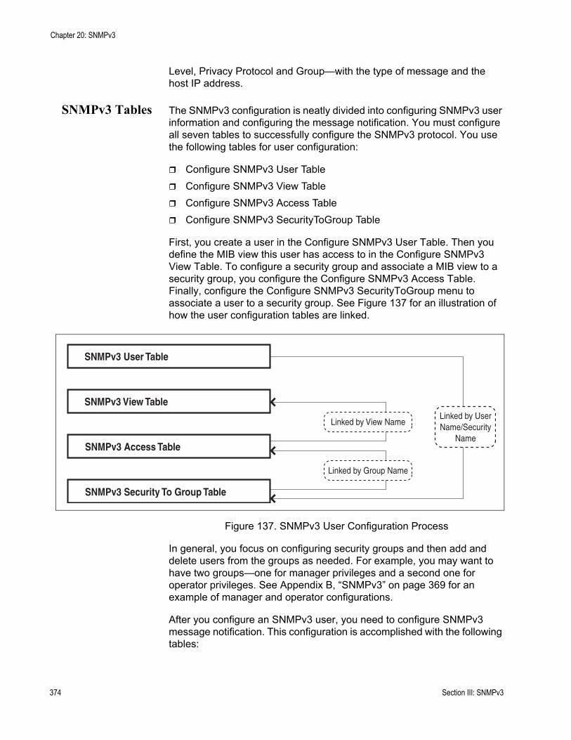
Chapter 20: SNMPv3
Level, Privacy Protocol and Group—with the type of message and the host IP address.
SNMPv3 Tables The SNMPv3 configuration is neatly divided into configuring SNMPv3 user information and configuring the message notification. You must configure all seven tables to successfully configure the SNMPv3 protocol. You use the following tables for user configuration:
Configure SNMPv3 User TableConfigure SNMPv3 View TableConfigure SNMPv3 Access TableConfigure SNMPv3 SecurityToGroup Table
First, you create a user in the Configure SNMPv3 User Table. Then you define the MIB view this user has access to in the Configure SNMPv3 View Table. To configure a security group and associate a MIB view to a security group, you configure the Configure SNMPv3 Access Table. Finally, configure the Configure SNMPv3 SecurityToGroup menu to associate a user to a security group. See Figure 137 for an illustration of how the user configuration tables are linked.
Figure 137. SNMPv3 User Configuration Process
In general, you focus on configuring security groups and then add and delete users from the groups as needed. For example, you may want to have two groups—one for manager privileges and a second one for operator privileges. See Appendix B, “SNMPv3” on page 369 for an example of manager and operator configurations.
After you configure an SNMPv3 user, you need to configure SNMPv3 message notification. This configuration is accomplished with the following tables:
SNMPv3 User Table
SNMPv3 View Table
SNMPv3 Access Table
SNMPv3 Security To Group Table
Linked by UserName/Security
Name
Linked by View Name
Linked by Group Name
374 Section III: SNMPv3
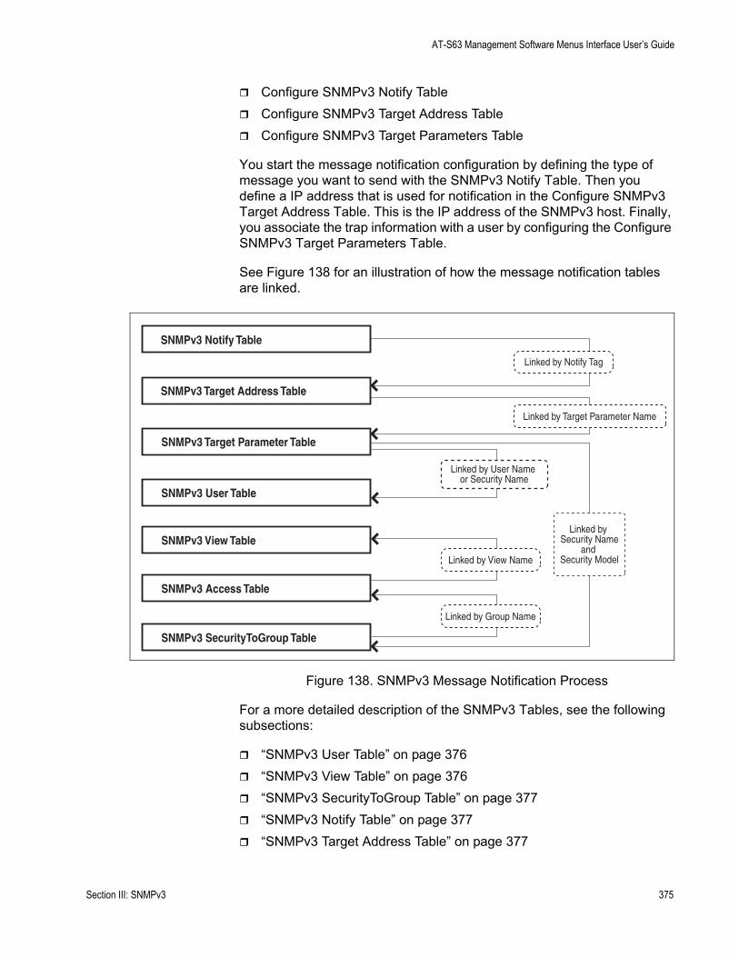
AT-S63 Management Software Menus Interface User’s Guide
Configure SNMPv3 Notify TableConfigure SNMPv3 Target Address TableConfigure SNMPv3 Target Parameters Table
You start the message notification configuration by defining the type of message you want to send with the SNMPv3 Notify Table. Then you define a IP address that is used for notification in the Configure SNMPv3 Target Address Table. This is the IP address of the SNMPv3 host. Finally, you associate the trap information with a user by configuring the Configure SNMPv3 Target Parameters Table.
See Figure 138 for an illustration of how the message notification tables are linked.
Figure 138. SNMPv3 Message Notification Process
For a more detailed description of the SNMPv3 Tables, see the following subsections:
“SNMPv3 User Table” on page 376“SNMPv3 View Table” on page 376“SNMPv3 SecurityToGroup Table” on page 377“SNMPv3 Notify Table” on page 377“SNMPv3 Target Address Table” on page 377
SNMPv3 Notify Table
SNMPv3 Target Address Table
SNMPv3 Target Parameter Table
SNMPv3 User Table
SNMPv3 View Table
SNMPv3 Access Table
SNMPv3 SecurityToGroup Table
Linked by View Name
Linked by Group Name
Linked by User Name or Security Name
Linked by Security Name
and Security Model
Linked by Notify Tag
Linked by Target Parameter Name
Section III: SNMPv3 375
Chapter 20: SNMPv3
“SNMPv3 Target Parameters Table” on page 377“SNMPv3 Community Table” on page 377
SNMPv3 User Table
The Configure SNMPv3 User Table menu allows you to create an SNMPv3 user and provides the options of configuring authentication and privacy protocols. With the SNMPv3 protocol, users are authenticated when they send and receive messages. In addition, you can configure a privacy protocol and password so messages a user sends and receives are encrypted. The DES privacy algorithm uses the privacy password and the Engine ID to generate a key that is used for encryption. Lastly, you can configure a storage type for this table entry which allows you to save this user and its related configuration to flash memory.
SNMPv3 View Table
The Configure SNMPv3 View Table menu allows you to create a view of the MIB OID Table. First, you configure a view of a subtree. Then you have the option of configuring a Subtree Mask that further refines the subtree view. For example, you can use a Subtree Mask to restrict a user’s view to one row of the MIB OID Table. In addition, you can chose to include or exclude a view. As a result, you can let a user see a particular view or prevent a user from seeing a particular view. Lastly, you can configure a storage type for this table entry which allows you to save this view to flash memory.
SNMPv3 Access Table
The Configure SNMPv3 Access Table menu allows you to configure a security group. After you create a security group, you assign a set of users with the same access privileges to this group using the SNMPv3 SecurityToGroup Table. Consider the types of groups you want to create and the types of access privileges each group will have. In this way, you can more easily keep track of your users as belonging to one or two groups.
For each group, you can assign read, write, and notify views of the MIB table. The views you assign here have been previously defined in the Configure SNMPv3 View Table menu. For example, the Read View allows group members to view the specified portion of the OID MIB table. The Write View allows group members to write to, or modify, the MIBs in the specified MIB view. The Notify View allows group members to send trap messages defined by the MIB view. Lastly, you can configure a storage type for this table entry which allows you to save this view to flash memory.
376 Section III: SNMPv3

AT-S63 Management Software Menus Interface User’s Guide
SNMPv3 SecurityToGroup Table
The Configure SNMPv3 SecurityToGroup Table menu allows you to associate a User Name with a security group called a Group Name. The User Name is previously configured with the Configure SNMPv3 User Table menu. The security group is previously configured with the Configure SNMPv3 Access Table menu. Lastly, you can configure a storage type for this table entry which allows you to save the entry to flash memory.
SNMPv3 Notify Table
The Configure SNMPv3 Notify Table menu allows you to define the type of message that is sent from the switch to the SNMP host. In addition, you have the option of defining the message type as either an Inform or a Trap message. The difference between these two types of messages is that when a switch sends an Inform message, the switch expects a response from the host. In comparison, the switch does not expect the host to respond to Trap messages.
In addition, you define a Notify Tag that links an SNMPv3 Notify Table entry to the host IP address defined in the Configure SNMPv3 Target Address Table menu. Lastly, you can configure a storage type for this table entry which allows you to save the entry to flash memory.
SNMPv3 Target Address Table
The Configure SNMPv3 Target Address Table menu allows you to configure the IP address of the host. Also, in an SNMPv3 Target Address Table entry, you configure the values of the Tag List parameter with the previously defined Notify Tag parameter values. The Notify Tag parameter is configured in the Configure SNMPv3 Notify Table. In this way, the Notify and Target Address tables are linked. Lastly, you can configure a storage type for this table entry which allows you to save the entry to flash memory.
SNMPv3 Target Parameters Table
The Configure SNMPv3 Target Parameters Table menu allows you to define which user can send messages to the host IP address defined in the Configure SNMPv3 Target Address Table. The user and its associated information is previously configured in the Configure SNMPv3 User Table, SNMPv3 View Table, SNMPv3 Access Table, and SNMPv3 SecurityToGroup Table. Lastly, you can configure a storage type for this table entry which allows you to save the entry to flash memory.
SNMPv3 Community Table
The Configure SNMPv3 Community Table menu allows you to configure SNMPv1 and SNMPv2c communities. If you are going to use the SNMPv3
Section III: SNMPv3 377
Chapter 20: SNMPv3
Tables to configure SNMPv1 and SNMPv2c communities, start with the SNMPv3 Community Table. See “Configuring the SNMPv3 Community Table” on page 455.
NoteAllied Telesyn recommends that you use the procedures described in Chapter 4, “SNMPv1 and SNMPv2c” on page 75 to configure the SNMPv1 and SNMPv2c protocols.
SNMPv3Configuration
Example
You may want to have two classes of SNMPv3 users—Managers and Operators. In this scenario, you would configure one group, called Managers, with full access privileges. Then you would configure a second group, called Operators, with monitoring privileges only. For a detailed example of this configuration, see Appendix B, “SNMPv3 Configuration Examples” on page 699.
378 Section III: SNMPv3
AT-S63 Management Software Menus Interface User’s Guide
Configuring SNMPv3 Entities
This section describes how to configure SNMPv3 entities using the SNMPv3 Tables. To successfully configure this protocol, you must perform the procedures in the order given. For overview information about SNMPv3, see the “SNMPv3 Overview” on page 370.
The following SNMPv3 tables are described:
“Configuring the SNMPv3 User Table,” next“Configuring the SNMPv3 View Table” on page 390“Configuring the SNMPv3 Access Table” on page 399“Configuring the SNMPv3 SecurityToGroup Table” on page 414“Configuring the SNMPv3 Notify Table” on page 422“Configuring the SNMPv3 Target Address Table” on page 429“Configuring the SNMPv3 Target Parameters Table” on page 442“Configuring the SNMPv3 Community Table” on page 455
The SNMPv3 User, View, Access, and SecurityToGroup tables are concerned with setting up a user, determining authentication and privacy, and associating a user to a security group. The SNMPv3 Notify, Target Address, and Target Parameters tables are concerned with message notification. You use the SNMPv3 Community Table to configure SNMPv1 and SNMPv2 communities.
Due to the complexity of the SNMPv3 configuration, Allied Telesyn recommends that you configure the SNMPv3 protocol with the procedures listed above, in the order they are listed. However, you can configure the SNMPv3 protocol using the above procedures in any order.
Section III: SNMPv3 379

Chapter 20: SNMPv3
Configuring the SNMPv3 User Table
This section contains a description of the SNMPv3 User Table and how to create, delete, and modify table entries. Configure the SNMPv3 User Table first. Creating this table, allows you to create an entry in an SNMPv3 User Table for a User Name. In addition, this table allows you to associate a User Name with the following parameters:
Authentication protocolAuthentication passwordPrivacy protocolPrivacy password
There are three functions you can perform with the SNMPv3 User Table.
“Creating an SNMPv3 User Table Entry,” next“Deleting an SNMPv3 User Table Entry” on page 384“Modifying an SNMPv3 User Table Entry” on page 384
Creating anSNMPv3 User
Table Entry
To create an entry in the SNMPv3 User Table, perform the following procedure:
1. From the Main Menu, type 5 to select System Administration.
The System Administration menu is shown in Figure 4 on page 46.
2. From the System Administration menu, type 5 to select SNMP Configuration.
The SNMP Configuration menu is shown in Figure 16 on page 79.
3. From the SNMP Configuration menu, type 5 to select Configure SNMPv3 Table.
380 Section III: SNMPv3
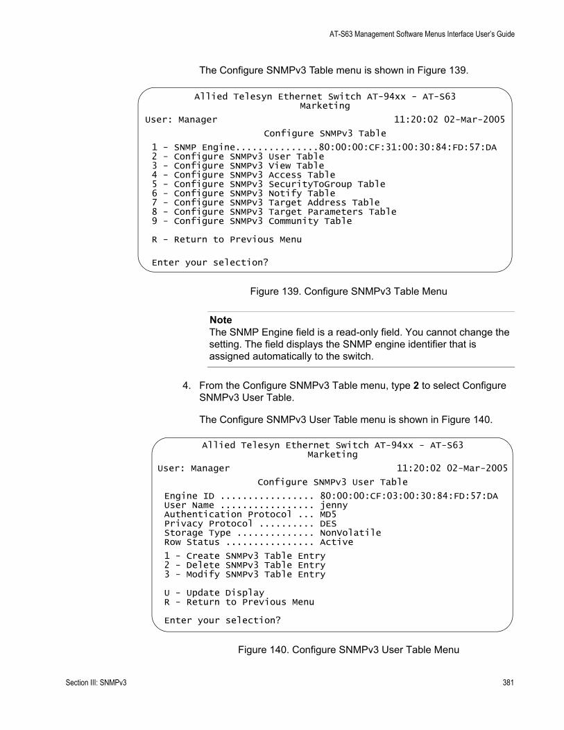
AT-S63 Management Software Menus Interface User’s Guide
The Configure SNMPv3 Table menu is shown in Figure 139.
Figure 139. Configure SNMPv3 Table Menu
NoteThe SNMP Engine field is a read-only field. You cannot change the setting. The field displays the SNMP engine identifier that is assigned automatically to the switch.
4. From the Configure SNMPv3 Table menu, type 2 to select Configure SNMPv3 User Table.
The Configure SNMPv3 User Table menu is shown in Figure 140.
Figure 140. Configure SNMPv3 User Table Menu
Allied Telesyn Ethernet Switch AT-94xx - AT-S63Marketing
User: Manager 11:20:02 02-Mar-2005
Configure SNMPv3 Table
1 - SNMP Engine...............80:00:00:CF:31:00:30:84:FD:57:DA2 - Configure SNMPv3 User Table3 - Configure SNMPv3 View Table4 - Configure SNMPv3 Access Table5 - Configure SNMPv3 SecurityToGroup Table6 - Configure SNMPv3 Notify Table7 - Configure SNMPv3 Target Address Table8 - Configure SNMPv3 Target Parameters Table9 - Configure SNMPv3 Community Table
R - Return to Previous Menu
Enter your selection?
Allied Telesyn Ethernet Switch AT-94xx - AT-S63Marketing
User: Manager 11:20:02 02-Mar-2005
Configure SNMPv3 User Table
Engine ID ................. 80:00:00:CF:03:00:30:84:FD:57:DAUser Name ................. jennyAuthentication Protocol ... MD5Privacy Protocol .......... DESStorage Type .............. NonVolatileRow Status ................ Active
1 - Create SNMPv3 Table Entry 2 - Delete SNMPv3 Table Entry3 - Modify SNMPv3 Table Entry
U - Update DisplayR - Return to Previous Menu
Enter your selection?
Section III: SNMPv3 381
Chapter 20: SNMPv3
5. To create a new user table, type 1 to select Create SNMPv3 Table Entry.
The following prompt is displayed:
Enter User (Security) Name:
6. Enter a descriptive name of the user.
You can enter a name that consists of up to 32 alphanumeric characters.
The following prompt is displayed:
Enter Authentication Protocol [M-MD5, S-SHA, N-None]:
7. Enter one of the following:
M-MD5This value represents the MD5 authentication protocol. With this selection, users (SNMP entities) are authenticated with the MD5 authentication protocol after a message is received. This algorithm generates the message digest. The user is authenticated when the authentication protocol checks the message digest. With the MD5 selection, you can configure a Privacy Protocol.
S-SHAThis value represents the SHA authentication protocol. With this selection, users are authenticated with the SHA authentication protocol after a message is received. This algorithm generates the message digest. The user is authenticated when the authentication protocol checks the message digest. With the SHA selection, you can configure a Privacy Protocol.
N-NoneThis value represents no authentication protocol. When messages are received, users are not authenticated. With the None selection, you cannot configure a Privacy Protocol.
NoteYou may want to assign NONE to a super user.
If you select NONE, you are prompted for the Storage Type. Go to Step 13.
If you select MD5 or SHA, the following prompt is displayed:
Enter Authentication Password:
8. Enter an authentication password of up to 32 alphanumeric characters and press Return.
382 Section III: SNMPv3
AT-S63 Management Software Menus Interface User’s Guide
You are prompted to re-enter the password.
The following prompt is displayed:
Enter Privacy Protocol [D-DES, N-None]:
NoteYou can only configure the Privacy Protocol if you have configured the Authentication Protocol with the MD5 or SHA values.
9. Select one of the following options:
D -DESSelect this value to make the DES privacy (or encryption) protocol the privacy protocol for this User Table entry. With this selection, messages transmitted between the host and the switch are encrypted with the DES protocol.
N -NoneSelect this value if you do not want a privacy protocol for this User Table entry. With this selection, messages transmitted between the host and the switch are not encrypted.
If you select NONE, you are prompted for the Storage Type. Go to Step 13.
If you select DES, the following prompt is displayed:
Enter Privacy Password:
10. Enter a privacy password of up to 32 alphanumeric characters.
You are prompted to re-enter the password.
The following prompt is displayed:
Enter Storage Type [V-Volatile, N-NonVolatile]:
11. Select one of the following storage types for this table entry:
V - VolatileSelect this storage type if you do not want the ability to save an entry in the SNMPv3 User Table to nonvolatile memory. After making changes to an SNMPv3 User Table entry with a Volatile storage type, the S - Save Configuration Changes option does not appear on the Main Menu.
N-NonVolatileSelect this storage type if you want the ability to save an entry in the SNMPv3 User Table to nonvolatile memory. After making changes to an SNMPv3 User Table entry with a NonVolatile storage type, the S - Save Configuration Changes option appears on the Main Menu,
Section III: SNMPv3 383
Chapter 20: SNMPv3
allowing you to save your changes. Allied Telesyn recommends this storage type.
NoteThe Row Status parameter is a read-only field. The Active value indicates the SNMPv3 User Table entry takes effect immediately.
12. After making changes, type R until you return to the Main Menu. Then type S to select Save Configuration Changes.
Deleting anSNMPv3 User
Table Entry
You may want to delete an entry from the SNMPv3 User Table. When you delete an entry in the SNMPv3 User Table, there is no way to undelete, or recover the entry.
To delete an entry in the SNMPv3 User Table, perform the following procedure.
1. Follow steps 1 through 5 in the procedure described in “Configuring the SNMPv3 User Table” on page 380. Or, from the Main Menu type 5->1->1->8->5.
The Configure SNMPv3 Table menu is shown in Figure 139 on page 381.
2. From the Configure SNMPv3 Table menu, type 2 to select Configure SNMPv3 User Table.
The SNMPv3 User Table is shown in Figure 140 on page 381.
3. From the SNMPv3 User Table, type 2 to select Delete SNMPv3 Table Entry.
The following prompt is displayed:
Enter User (Security) Name:
4. Enter the User Name of the User Table entry you want to delete.
The following prompt is displayed:
Do you want to delete this table entry? (Y/N):[Yes/No]->
5. Enter Y to delete the user or N to save the user.
6. After making changes, type R until you return to the Main Menu. Then type S to select Save Configuration Changes.
Modifying anSNMPv3 User
Table Entry
This section describes how to modify parameters in an SNMPv3 Notify Table entry. See the following procedures:
“Modifying the Authentication Protocol and Password” on page 385
384 Section III: SNMPv3
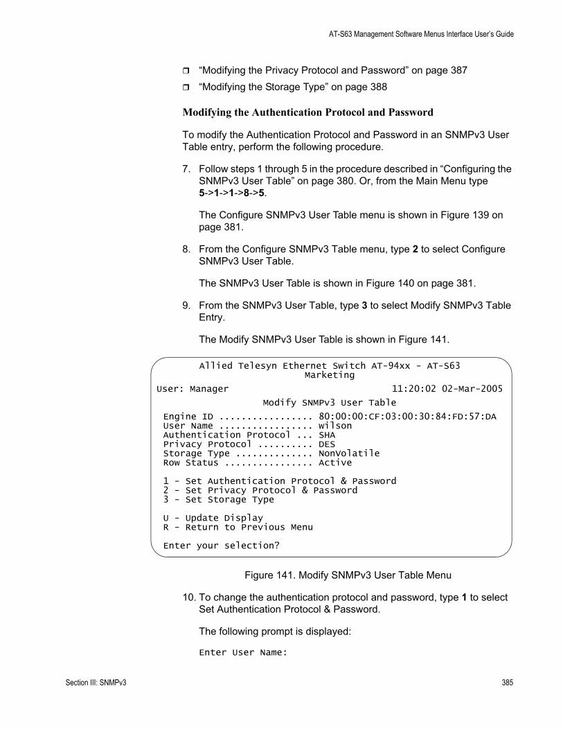
AT-S63 Management Software Menus Interface User’s Guide
“Modifying the Privacy Protocol and Password” on page 387“Modifying the Storage Type” on page 388
Modifying the Authentication Protocol and Password
To modify the Authentication Protocol and Password in an SNMPv3 User Table entry, perform the following procedure.
7. Follow steps 1 through 5 in the procedure described in “Configuring the SNMPv3 User Table” on page 380. Or, from the Main Menu type 5->1->1->8->5.
The Configure SNMPv3 User Table menu is shown in Figure 139 on page 381.
8. From the Configure SNMPv3 Table menu, type 2 to select Configure SNMPv3 User Table.
The SNMPv3 User Table is shown in Figure 140 on page 381.
9. From the SNMPv3 User Table, type 3 to select Modify SNMPv3 Table Entry.
The Modify SNMPv3 User Table is shown in Figure 141.
Figure 141. Modify SNMPv3 User Table Menu
10. To change the authentication protocol and password, type 1 to select Set Authentication Protocol & Password.
The following prompt is displayed:
Enter User Name:
Allied Telesyn Ethernet Switch AT-94xx - AT-S63Marketing
User: Manager 11:20:02 02-Mar-2005
Modify SNMPv3 User Table
Engine ID ................. 80:00:00:CF:03:00:30:84:FD:57:DAUser Name ................. wilsonAuthentication Protocol ... SHAPrivacy Protocol .......... DESStorage Type .............. NonVolatileRow Status ................ Active
1 - Set Authentication Protocol & Password2 - Set Privacy Protocol & Password3 - Set Storage Type
U - Update DisplayR - Return to Previous Menu
Enter your selection?
Section III: SNMPv3 385
Chapter 20: SNMPv3
11. Enter the User Name of the User Table you want to modify.
The following prompt is displayed:
Enter Authentication Protocol [M-MD5, S-SHA, N-None]:
12. Enter one of the following:
M-MD5This value represents the MD5 authentication protocol. With this selection, users (SNMP entities) are authenticated with the MD5 authentication protocol after a message is received. This algorithm generates the message digest. The user is authenticated when the authentication protocol checks the message digest. With the MD5 selection, you can configure a Privacy Protocol.
S-SHAThis value represents the SHA authentication protocol. With this selection, users are authenticated with the SHA authentication protocol after a message is received. This algorithm generates the message digest. The user is authenticated when the authentication protocol checks the message digest. With the SHA selection, you can configure a Privacy Protocol.
N-NoneThis value represents no authentication protocol. When messages are received, users are not authenticated. With the None selection, you cannot configure a Privacy Protocol.
If you select None, go to step 9.
If you select MD5 or SHA, the following prompt is displayed:
Enter Authentication Password:
13. Enter an authentication password of up to 32 alphanumeric characters.
The following prompt is displayed:
Re-enter Authentication password:
14. Re-enter the password.
The following message is displayed:
Authentication protocol algorithm has been changed.
The following prompt is displayed:
Please enter privacy password to regenerate privacy key.
15. Enter the Privacy Password for this User Name.
The following prompt is displayed:
386 Section III: SNMPv3
AT-S63 Management Software Menus Interface User’s Guide
Re-enter Privacy password:
16. Re-enter the password.
17. After making changes, type R until you return to the Main Menu. Then type S to select Save Configuration Changes.
Modifying the Privacy Protocol and Password
To modify the Privacy Protocol and Password in an SNMPv3 User Table entry, perform the following procedure.
NoteYou can only configure the Privacy Protocol if you have configured the Authentication Protocol with the MD5 or SHA values.
1. Follow steps 1 through 5 in the procedure described in “Configuring the SNMPv3 User Table” on page 380. Or, from the Main Menu type 5->1->1->8->5.
The Configure SNMPv3 User Table menu is shown in Figure 139 on page 381.
2. From the Configure SNMPv3 Table menu, type 2 to select Configure SNMPv3 User Table.
The SNMPv3 User Table is shown in Figure 140 on page 381.
3. From the SNMPv3 User Table, type 3 to select Modify SNMPv3 Table Entry.
The Modify SNMPv3 Table menu is shown in Figure 141 on page 385.
4. Type 2 to select Privacy Protocol & Password.
The following prompt is displayed:
Enter User (Security) Name:
5. Enter the User Name.
The following prompt is displayed:
Enter Privacy Protocol [D-DES, N-None]:
6. Choose one of the following Privacy Protocols:
D -DESSelect this value to make the DES privacy (or encryption) protocol the privacy protocol for this User Table entry. With this selection,
Section III: SNMPv3 387

Chapter 20: SNMPv3
messages transmitted between the host and the switch are encrypted with the DES protocol.
N -NoneSelect this value if you do not want a privacy protocol for this User Table entry. With this selection, messages transmitted between the host and the switch are not encrypted.
If you select None, proceed to step 9.
If you select DES, the following prompt is displayed:
Enter Privacy Password:
7. Enter a privacy password of up to 32 alphanumeric characters.
The following prompt is displayed:
Re-enter Authentication password:
8. Re-enter the password.
9. After making changes, type R until you return to the Main Menu. Then type S to select Save Configuration Changes.
Modifying the Storage Type
To modify the Storage Type in an SNMPv3 User Table entry, perform the following procedure.
1. Follow steps 1 through 5 in the procedure described in “Configuring the SNMPv3 User Table” on page 380. Or, from the Main Menu type 5->1->1->8->5.
The Configure SNMPv3 User Table menu is shown in Figure 139 on page 381.
2. From the Configure SNMPv3 Table menu, type 2 to select Configure SNMPv3 User Table.
The SNMPv3 User Table is shown in Figure 140 on page 381.
3. From the SNMPv3 User Table, type 3 to select Modify SNMPv3 Table Entry.
The Modify SNMPv3 Table menu is shown in Figure 141 on page 385.
4. To change the storage type, type 3 to select Set Storage Type.
The following prompt is displayed:
Enter User (Security) Name:
388 Section III: SNMPv3
AT-S63 Management Software Menus Interface User’s Guide
5. Enter the User Name.
The following prompt is displayed:
Enter Storage Type [V-Volatile, N-NonVolatile]:
6. Select one of the following storage types for this table entry:
V - VolatileSelect this storage type if you do not want the ability to save an entry in the SNMPv3 User Table to nonvolatile memory. After making changes to an SNMPv3 User Table entry with a Volatile storage type, the S - Save Configuration Changes option does not appear on the Main Menu.
N-NonVolatileSelect this storage type if you want the ability to save an entry in the SNMPv3 User Table to nonvolatile memory. After making changes to an SNMPv3 User Table entry with a NonVolatile storage type, the S - Save Configuration Changes option appears on the Main Menu, allowing you to save your changes. Allied Telesyn recommends this storage type.
7. After making changes, type R until you return to the Main Menu. Then type S to select Save Configuration Changes.
Section III: SNMPv3 389
Chapter 20: SNMPv3
Configuring the SNMPv3 View Table
This section contains a description of the SNMPv3 View Table and how to create, delete, and modify table entries. Creating this table, allows you to specify a view using the following parameters:
Subtree OIDSubtree MaskMIB OID Table View
To configure the SNMPv3 View Table, you need to be very familiar with the OID table. You can be very specific about the view a user can or cannot access—down to a column or row of the table. AT-S63 supports the Internet subtree of the OID table.
There are three functions you can perform with the SNMPv3 User Table:
“Creating an SNMPv3 View Table Entry,” next“Deleting an SNMPv3 View Table Entry” on page 393“Modifying an SNMPv3 View Table Entry” on page 394
Creating anSNMPv3 View
Table Entry
To create an entry in the SNMPv3 View Table, perform the following procedure.
1. Follow steps 1 through 5 in the procedure described in “Creating an SNMPv3 User Table Entry” on page 380. Or, from the Main Menu type 5->1->1->8->5.
The Configure SNMPv3 Table menu is shown in Figure 139 on page 381.
2. From the Configure SNMPv3 Table menu, type 3 to select Configure SNMPv3 View Table.
390 Section III: SNMPv3

AT-S63 Management Software Menus Interface User’s Guide
The Configure SNMPv3 View Table menu is shown in Figure 142.
Figure 142. Configure SNMPv3 View Table Menu
3. From the Configure SNMPv3 View Table menu, type 1 to select Create SNMPv3 Table Entry.
The following prompt is displayed:
Enter View Name:
4. Enter a descriptive name of this View.
Enter a unique name of up to 32 alphanumeric characters.
NoteThe “defaultViewAll” value is the default entry for the SNMPv1 and SNMPv2c configuration. You cannot use the default value for an SNMPv3 View Table entry.
The following prompt is displayed:
Enter View Subtree (OID format/Text Name):
5. Enter the subtree that this view will or will not be permitted to display.
You can enter either a numeric value in hex format or the equivalent text name. For example, the OID hex format for TCP/IP is:
1.3.6.1.2.1.6
The text format is for TCP/IP is:
Allied Telesyn Ethernet Switch AT-94xx - AT-S63Marketing
User: Manager 11:20:02 02-Mar-2005
Configure SNMPv3 View Table
View Name ................. internetSubtree OID ............... 1.3.6.1Subtree Mask .............. View Type ................. IncludedStorage Type .............. NonVolatileRow Status ................ Active
1 - Create SNMPv3 Table Entry 2 - Delete SNMPv3 Table Entry3 - Modify SNMPv3 Table Entry
U - Update DisplayR - Return to Previous Menu
Enter your selection?
Section III: SNMPv3 391

Chapter 20: SNMPv3
tcp
The following prompt is displayed:
Enter Subtree Mask (Hex format):
6. Enter a subtree mask in hexadecimal format.
This is an optional parameter that is used to further refine the value in the View Subtree parameter. This parameter is in binary format.
The relationship between a subtree mask and a subtree is similar to the relationship between an IP address and a subnet mask. The subnet mask further refines the IP address. In the same way, the OID table entry defines a MIB View and the subtree mask further restricts a user’s view to a specific the column and row of the MIB View. The value of the Subnet Mask parameter is dependent on the subtree you select. For example, if you configure the View Subtree parameter as MIB, ifEntry.0.3 has the following value:
1.3.6.1.2.1.2.2.1.0.3
To restrict the user’s view to the third row (all columns) of the ifEntry MIB, enter the following value for the Subtree Mask parameter
ff:bf
The following prompt is displayed:
Enter View Type [I-Included, E-Excluded]:
7. Enter one of the following view types:
I - IncludedEnter this value to permit the View Name to see the subtree specified above.
E - ExcludedEnter this value to not permit the View Name to see the subtree specified above.
The following prompt is displayed:
Enter Storage Type [V-Volatile, N-NonVolatile]:
8. Select one of the following storage types for this table entry:
V - VolatileSelect this storage type if you do not want the ability to save an entry in the SNMPv3 View Table to the configuration file. After making changes to an SNMPv3 View Table entry with a Volatile storage type, the S - Save Configuration Changes option does not appear on the Main Menu.
392 Section III: SNMPv3
AT-S63 Management Software Menus Interface User’s Guide
N-NonVolatileSelect this storage type if you want the ability to save an entry in the SNMPv3 View Table to the configuration file. After making changes to an SNMPv3 View Table entry with a NonVolatile storage type, the S - Save Configuration Changes option appears on the Main Menu, allowing you to save your changes. Allied Telesyn recommends this storage type.
NoteThe Row Status parameter is a read-only field. The Active value indicates the SNMPv3 View Table entry takes effect immediately.
9. After making changes, type R until you return to the Main Menu. Then type S to select Save Configuration Changes.
Deleting anSNMPv3 View
Table Entry
You may want to delete an entry from the SNMPv3 View Table. After you delete an SNMPv3 View Table entry, there is no way to undelete, or recover the entry.
To delete an entry in the SNMPv3 View Table, perform the following procedure:
1. Follow steps 1 through 5 in the procedure described in “Creating an SNMPv3 User Table Entry” on page 380. Or, from the Main Menu type 5->1->1->8->5.
The Configure SNMPv3 Table menu is shown in Figure 139 on page 381.
2. From the Configure SNMPv3 Table menu, type 3 to select Configure SNMPv3 View Table.
The SNMPv3 View Table is shown in Figure 142 on page 391.
3. From the SNMPv3 View Table, type 2 to select Delete SNMPv3 Table Entry.
The following prompt is displayed:
Enter View Name:
4. Enter the View Name of the View Table entry you want to delete.
The following prompt is displayed:
Enter View Subtree (OID format/Text Name):
5. Enter the subtree for this view.
Do you want to delete this table entry? (Y/N):[Yes/No]->
Section III: SNMPv3 393
Chapter 20: SNMPv3
6. Enter Y to delete the view or N to save the view.
7. After making changes, type R until you return to the Main Menu. Then type S to select Save Configuration Changes.
Modifying anSNMPv3 View
Table Entry
This section describes how to modify parameters in an SNMPv3 Notify Table entry. See the following procedures:
“Modifying a Subtree Mask” on page 394“Modifying a View Type” on page 396“Modifying a Storage Type” on page 397
Modifying a Subtree Mask
To modify the Subtree Mask parameter in an SNMPv3 View Table entry, perform the following procedure.
1. Follow steps 1 through 5 in the procedure described in “Creating an SNMPv3 User Table Entry” on page 380. Or, from the Main Menu type 5->1->1->8->5.
The Configure SNMPv3 Table menu is shown in Figure 139 on page 381.
2. From the Configure SNMPv3 Table menu, type 3 to select Configure SNMPv3 View Table.
The Configure SNMPv3 View Table menu is shown in Figure 142 on page 391.
3. From the Configure SNMPv3 View Table menu, type 3 to select Modify SNMPv3 Table Entry.
394 Section III: SNMPv3
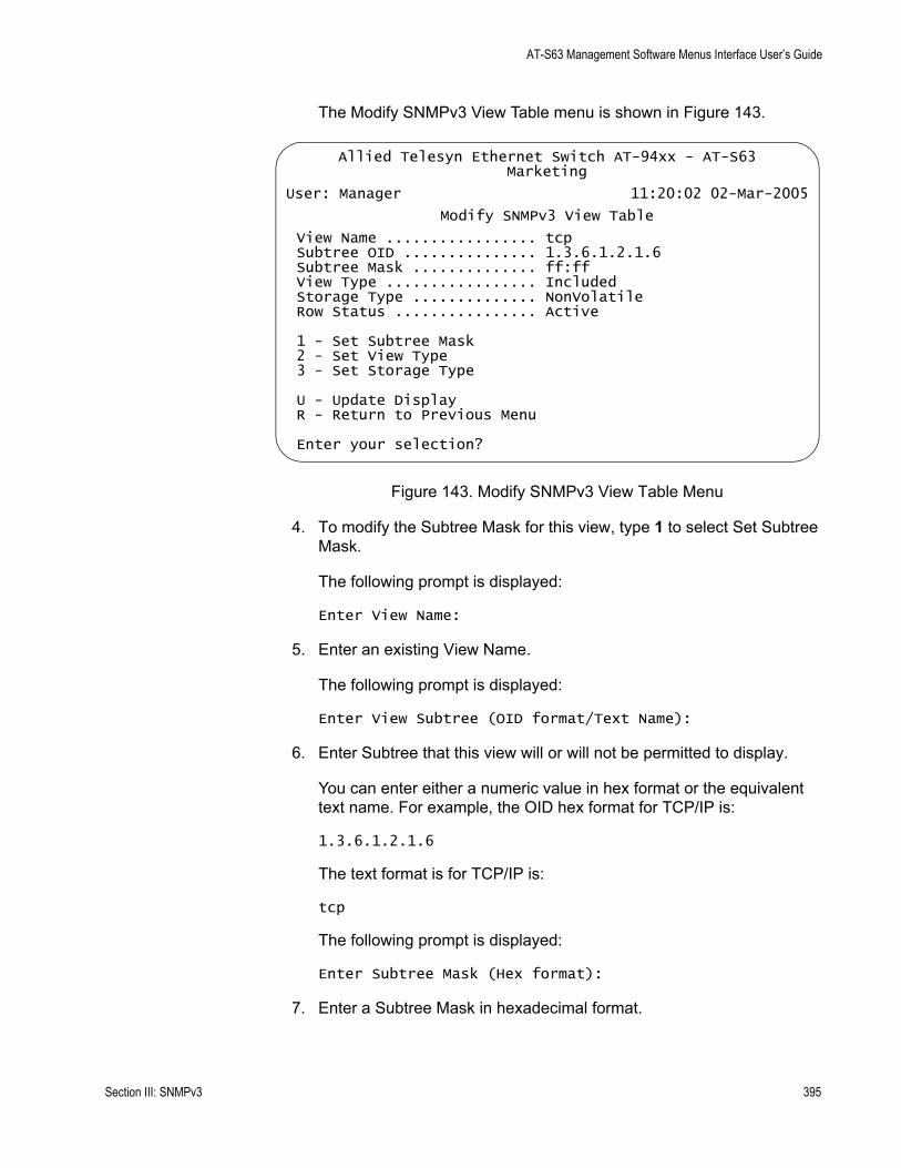
AT-S63 Management Software Menus Interface User’s Guide
The Modify SNMPv3 View Table menu is shown in Figure 143.
Figure 143. Modify SNMPv3 View Table Menu
4. To modify the Subtree Mask for this view, type 1 to select Set Subtree Mask.
The following prompt is displayed:
Enter View Name:
5. Enter an existing View Name.
The following prompt is displayed:
Enter View Subtree (OID format/Text Name):
6. Enter Subtree that this view will or will not be permitted to display.
You can enter either a numeric value in hex format or the equivalent text name. For example, the OID hex format for TCP/IP is:
1.3.6.1.2.1.6
The text format is for TCP/IP is:
tcp
The following prompt is displayed:
Enter Subtree Mask (Hex format):
7. Enter a Subtree Mask in hexadecimal format.
Allied Telesyn Ethernet Switch AT-94xx - AT-S63Marketing
User: Manager 11:20:02 02-Mar-2005
Modify SNMPv3 View Table
View Name ................. tcpSubtree OID ............... 1.3.6.1.2.1.6Subtree Mask .............. ff:ffView Type ................. IncludedStorage Type .............. NonVolatileRow Status ................ Active
1 - Set Subtree Mask2 - Set View Type3 - Set Storage Type
U - Update DisplayR - Return to Previous Menu
Enter your selection?
Section III: SNMPv3 395
Chapter 20: SNMPv3
This is an optional parameter that is used to further refine the value in the View Subtree parameter. This parameter is in binary format.
A subtree mask and a subtree have a similar relationship as an IP address and a subnet mask. The subnet mask further refines the IP address. In the same way, the OID table entry defines a MIB View and the subtree mask further restricts a user’s view to a specific the column and row of the MIB View. The value of the Subnet Mask parameter is dependent on the subtree you select. For example, if you configure the View Subtree parameter as MIB, ifEntry.0.3 has the following value:
1.3.6.1.2.1.2.2.1.0.3
To restrict the user’s view to the third row (all columns) of the ifEntry MIB, enter the following value for the Subtree Mask parameter:
ff:bf
8. After making changes, type R until you return to the Main Menu. Then type S to select Save Configuration Changes.
Modifying a View Type
To modify the View Type parameter in an SNMPv3 View Table entry, perform the following procedure.
1. Follow steps 1 through 5 in the procedure described in “Creating an SNMPv3 User Table Entry” on page 380. Or, from the Main Menu type 5->1->1->8->5.
The Configure SNMPv3 Table menu is shown in Figure 139 on page 381.
2. From the Configure SNMPv3 Table menu, type 3 to select Configure SNMPv3 View Table.
The Configure SNMPv3 View Table menu is shown in Figure 142 on page 391.
3. From the Configure SNMPv3 View Table menu, type 3 to select Modify SNMPv3 Table Entry.
The Modify SNMPv3 Table menu is shown in Figure 143 on page 395.
4. To modify the View Type, type 2 to select Set View Type.
The following prompt is displayed:
Enter View Name:
5. Enter a View Name that was previously configured.
396 Section III: SNMPv3
AT-S63 Management Software Menus Interface User’s Guide
The following prompt is displayed:
Enter View Subtree (OID format/Text Name):
6. Enter the View Subtree value for this View Name.
You can enter either a numeric value in hex format or the equivalent text name. For example, the OID hex format for TCP/IP is:
1.3.6.1.2.1.6
The text format is for TCP/IP is:
tcp
The following prompt is displayed:
Enter View Type [I-Included, E-Excluded]:
7. Choose one of the following view types:
I - IncludedEnter this value to permit the View Name to see the subtree specified above.
E - ExcludedEnter this value to not permit the View Name to see the subtree specified above.
8. After making changes, type R until you return to the Main Menu. Then type S to select Save Configuration Changes.
Modifying a Storage Type
To modify the Storage Type parameter in an SNMPv3 View Table entry, perform the following procedure.
1. Follow steps 1 through 5 in the procedure described in “Creating an SNMPv3 User Table Entry” on page 380. Or, from the Main Menu type 5->1->1->8->5.
The Configure SNMPv3 Table menu is shown in Figure 139 on page 381.
2. From the Configure SNMPv3 Table menu, type 3 to select Configure SNMPv3 View Table.
The Configure SNMPv3 View Table menu is shown in Figure 142 on page 391.
3. From the Configure SNMPv3 View Table menu, type 3 to select Modify SNMPv3 Table Entry.
Section III: SNMPv3 397
Chapter 20: SNMPv3
The Modify SNMPv3 Table menu is shown in Figure 143 on page 395.
4. To modify the storage type, type 3 to select Set Storage Type.
The following prompt is displayed:
Enter View Name:
5. Enter the View Name you want to modify.
The following prompt is displayed:
Enter View Subtree (OID format/Text Name):
6. Enter the View Subtree for this View Name.
The following prompt is displayed:
Enter Storage Type [V-Volatile, N-Nonvolatile]:
7. Select one of the following storage types for this table entry:
V - VolatileSelect this storage type if you do not want the ability to save an entry in the SNMPv3 View Table to the configuration file. After making changes to an SNMPv3 View Table entry with a Volatile storage type, the S - Save Configuration Changes option does not appear on the Main Menu.
N-NonVolatileSelect this storage type if you want the ability to save an entry in the SNMPv3 View Table to the configuration file. After making changes to an SNMPv3 View Table entry with a NonVolatile storage type, the S - Save Configuration Changes option appears on the Main Menu, allowing you to save your changes. Allied Telesyn recommends this storage type.
8. After making changes, type R until you return to the Main Menu. Then type S to select Save Configuration Changes.
398 Section III: SNMPv3
AT-S63 Management Software Menus Interface User’s Guide
Configuring the SNMPv3 Access Table
This section contains a description of the SNMPv3 Access Table and how to create, delete, and modify table entries. The SNMPv3 Access Table allows you to configure a security group. Each user must belong to a security group. After you have configured a security group, use the SecurityToGroup Table to assign users to security groups. See “Creating an SNMPv3 SecurityToGroup Table Entry” on page 414.
For each security group, you can assign the following attributes:
a Security Model (SNMPv1, SNMPv2c, SNMPv3)Read, write, and notify viewsA security levelA storage type
Before you begin this procedure, you will need to configure entries in the View Table. These values are used to configure the Read, Write, and Notify View parameters in this procedure. See “Configuring the SNMPv3 View Table” on page 390.
There are three functions you can perform with the SNMPv3 Access Table.
“Creating an SNMPv3 Access Table Entry,” next“Deleting an SNMPv3 Access Table Entry” on page 403“Modifying an SNMPv3 Access Table Entry” on page 405
Creating anSNMPv3 Access
Table Entry
To create an entry in the SNMPv3 Access Table, perform the following procedure.
1. Follow steps 1 through 5 in the procedure described in “Creating an SNMPv3 User Table Entry” on page 380. Or, from the Main Menu type 5->1->1->8->5.
The Configure SNMPv3 Table menu is shown in Figure 139 on page 381.
2. From the Configure SNMPv3 Table menu, type 4 to select Configure SNMPv3 Access Table.
Section III: SNMPv3 399

Chapter 20: SNMPv3
The Configure SNMPv3 Access Table menu is shown in Figure 144.
Figure 144. Configure SNMPv3 Access Table Menu
3. To create a group in the SNMPv3 Access Table, type 1 to select Create SNMPv3 Table Entry.
The following prompt is displayed:
Enter Group Name:
4. Enter a descriptive name of the group. The Group Name can consist of up to 32 alphanumeric characters.
The Group Name can consist of up to 32 alphanumeric characters.
You are not required to enter a unique value here because the SNMPv3 Access Table entry is index with the Group Name, Security Model, and Security Level parameter values. However, unique group names allow you to more easily distinguish the groups.
There are four default values for this field:
defaultV1GroupReadOnlydefaultV1GroupReadWritedefaultV2cGroupReadOnlydefaultV2cGroupReadWrite
These values are reserved for SNMPv1 and SNMPv2c implementations.
Allied Telesyn Ethernet Switch AT-94xx - AT-S63Marketing
User: Manager 11:20:02 02-Mar-2005
Configure SNMPv3 Access Table
Group Name .... softwareengineering Security Model . v3Context Prefix. Security Level . AuthPrivRead View...... internet Context Match .. ExactWrite View .... tcp Storage Type ... NonVolatileNotify View ... tcp Row Status ..... Active
1 - Create SNMPv3 Table Entry 2 - Delete SNMPv3 Table Entry3 - Modify SNMPv3 Table Entry
U - Update DisplayR - Return to Previous Menu
Enter your selection?
400 Section III: SNMPv3

AT-S63 Management Software Menus Interface User’s Guide
NoteThe Context Prefix and the Context Match fields are a read only fields. The Context Prefix field is always set to null. The Context Match field is always set to exact.
The following prompt is displayed:
Enter Security Model [1-v1, 2-v2c, 3-v3]:
5. Select one of the following SNMP protocols as the Security Model for this Group Name.
1-v1Select this value to associate the Group Name with the SNMPv1 protocol.
2-v2cSelect this value to associate the Group Name with the SNMPv2c protocol.
3-v3Select this value to associate the Group Name with the SNMPv3 protocol. The SNMPv3 protocol allows you to configure the group to authenticate SNMPv3 entities (users) and encrypt messages.
The following prompt is displayed:
Enter Security Level [N-NoAuthNoPriv, A-AuthNoPriv, P-AuthPriv]:
6. Select one of the following security levels:
N-NoAuthNoPrivThis option represents no authentication and no privacy protocol. Select this security level if you do not want to authenticate SNMP entities and you do not want to encrypt messages using a privacy protocol. This security level provides the least security.
NoteIf you have selected SNMPv1 or SNMPv2c, N-NoAuthNoPriv is the only security level you can select.
A-AuthNoPrivThis option represents authentication, but no privacy protocol. Select this security level if you want to authenticate SNMP users, but you do not want to encrypt messages using a privacy protocol.You can select this value if you configured the Security Model parameter with the SNMPv3 protocol.
Section III: SNMPv3 401

Chapter 20: SNMPv3
P-AuthPrivThis option represents authentication and the privacy protocol. Select this security level to encrypt messages using a privacy protocol and authenticate SNMP entities. This level provides the greatest level of security. You can select this value if you configured the Security Model parameter with the SNMPv3 protocol.
The following prompt is displayed:
Enter Read View Name:
7. Enter a value that you configured with the View Name parameter in the SNMPv3 View Table.
A Read View Name allows the users assigned to this Group Name to view the information specified by the View Table entry. This value does not need to be unique.
The following prompt is displayed:
Enter Write View Name:
8. Enter a value that you configured with the View Name parameter in the SNMPv3 View Table.
A Write View Name allows the users assigned to this Security Group to write, or modify, the information in the specified View Table. This value does not need to be unique.
The following prompt is displayed:
Enter Notify View Name:
9. Enter a value that you configured with the View Name parameter in the SNMPv3 View Table.
A Notify View Name allows the users assigned to this Group Name to send traps permitted in the specified View. This value does not need to be unique.
The following prompt is displayed:
Enter Storage Type [V-Volatile, N-NonVolatile]:
10. Select one of the following storage types for this table entry:
V - VolatileSelect this storage type if you do not want the ability to save an entry in the SNMPv3 Access Table to the configuration file. After making changes to an SNMPv3 Access Table entry with a Volatile storage type, the S - Save Configuration Changes option does not appear on the Main Menu.
402 Section III: SNMPv3
AT-S63 Management Software Menus Interface User’s Guide
N-NonVolatileSelect this storage type if you want the ability to save an entry in the SNMPv3 Access Table to the configuration file. After making changes to an SNMPv3 Access Table entry with a NonVolatile storage type, the S - Save Configuration Changes option appears on the Main Menu, allowing you to save your changes. Allied Telesyn recommends this storage type.
NoteThe Row Status parameter is a read-only field. The Active value indicates the SNMPv3 Access Table entry will take effect immediately.
11. After making changes, type R until you return to the Main Menu. Then type S to select Save Configuration Changes.
Deleting anSNMPv3 Access
Table Entry
You may want to delete an entry from the SNMPv3 Access Table. After you delete an SNMPv3 Access Table, there is no way to undelete, or recover, the entry.
To delete an entry in the SNMPv3 Access Table, perform the following procedure:
1. Follow steps 1 through 5 in the procedure described in “Creating an SNMPv3 User Table Entry” on page 380. Or, from the Main Menu type 5->1->1->8->5.
The Configure SNMPv3 Table menu is shown in Figure 139 on page 381.
2. From the Configure SNMPv3 Table menu, type 4 to select Configure SNMPv3 Access Table.
The SNMPv3 Access Table is shown in Figure 144 on page 400.
NoteTo display a particular Group Name and its associated parameters from the Configure SNMPv3 Access Table menu, type N to display the Next Page and P to display the previous page.
3. From the SNMPv3 Access Table, type 2 to select Delete SNMPv3 Table Entry.
The following prompt is displayed:
Enter Group Name:
4. Enter the Group Name that you want to delete.
Section III: SNMPv3 403

Chapter 20: SNMPv3
The following prompt is displayed:
Enter Security Model [1-v1, 2-v2c, 3-v3]:
5. Enter the Security Model of this Group Name.
Select one of the following security levels:
1-v1Select this value to associate the Group Name with the SNMPv1 protocol.
2-v2cSelect this value to associate the Group Name with the SNMPv2c protocol.
3-v3Select this value to associate the Group Name with the SNMPv3 protocol. The following prompt is displayed:
Enter the Security Level [N-NoAuthNoPriv, A-AuthNoPriv, P-AuthPriv]:
6. Enter the Security Level of this Group Name.
Select one of the following Security Levels:
N-NoAuthNoPrivThis option represents no authentication and no privacy protocol. Select this security level if you do not want to authenticate SNMP entities and you do not want to encrypt messages using a privacy protocol. This security level provides the least security.
NoteIf you have selected SNMPv1 or SNMPv2c, N-NoAuthNoPriv is the only security level you can select.
A-AuthNoPrivThis option represents authentication, but no privacy protocol. Select this security level if you want to authenticate SNMP users, but you do not want to encrypt messages using a privacy protocol.You can select this value if you configured the Security Model parameter with the SNMPv3 protocol.
P-AuthPrivThis option represents authentication and the privacy protocol. Select this security level to encrypt messages using a privacy protocol and authenticate SNMP entities. This level provides the greatest level of security. You can select this value if you configured the Security Model parameter with the SNMPv3 protocol.
The following prompt is displayed:
404 Section III: SNMPv3
AT-S63 Management Software Menus Interface User’s Guide
Do you want to delete this table entry?(Y/N):[Yes/No]->
7. Enter Y to delete the view or N to save the view.
The following prompt is displayed:
8. After making changes, type R until you return to the Main Menu. Then type S to select Save Configuration Changes.
Modifying anSNMPv3 Access
Table Entry
This section describes how to modify parameters in an SNMPv3 Access Table entry. For each entry in the SNMPv3 Access Table, you can modify the following parameters:
Read View NameWrite View Name Notify View NameStorage Type
Configure the values of the Read View Name, Write View Name, and Notify View Name parameters with values previously configured with the View Name parameter in the SNMPv3 View Table. This is the only way to associate a Group Name with these Views. See “Creating an SNMPv3 View Table Entry” on page 390.
See the following procedures:
“Modifying the Read View Name” on page 405“Modifying the Write View Name” on page 407“Modifying the Notify View Name” on page 409“Modifying the Storage Type” on page 411
Modifying the Read View Name
To modify the Read View Name parameter in an SNMPv3 Access Table entry, perform the following procedure.
1. Follow steps 1 through 5 in the procedure described in “Creating an SNMPv3 User Table Entry” on page 380. Or, from the Main Menu type 5->1->1->8->5.
The Configure SNMPv3 Table menu is shown in Figure 139 on page 381.
2. From the Configure SNMPv3 Table menu, type 4 to select Configure SNMPv3 Access Table.
The Configure SNMPv3 Access Table is shown in Figure 144 on page 400.
Section III: SNMPv3 405
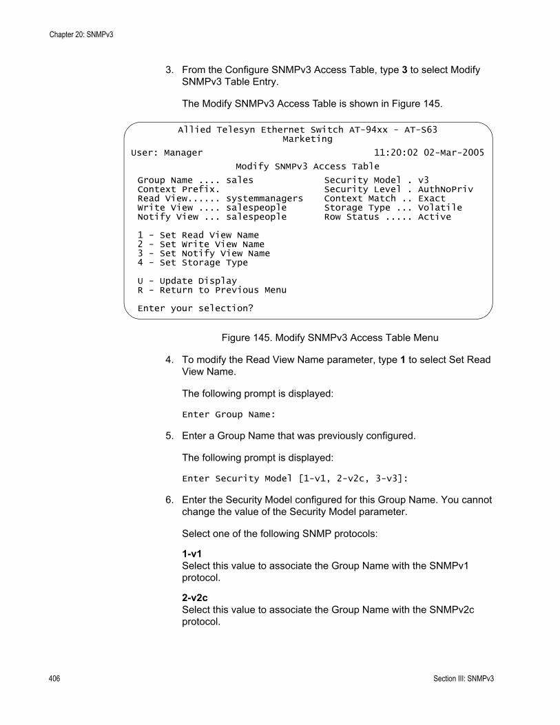
Chapter 20: SNMPv3
3. From the Configure SNMPv3 Access Table, type 3 to select Modify SNMPv3 Table Entry.
The Modify SNMPv3 Access Table is shown in Figure 145.
Figure 145. Modify SNMPv3 Access Table Menu
4. To modify the Read View Name parameter, type 1 to select Set Read View Name.
The following prompt is displayed:
Enter Group Name:
5. Enter a Group Name that was previously configured.
The following prompt is displayed:
Enter Security Model [1-v1, 2-v2c, 3-v3]:
6. Enter the Security Model configured for this Group Name. You cannot change the value of the Security Model parameter.
Select one of the following SNMP protocols:
1-v1Select this value to associate the Group Name with the SNMPv1 protocol.
2-v2cSelect this value to associate the Group Name with the SNMPv2c protocol.
Allied Telesyn Ethernet Switch AT-94xx - AT-S63Marketing
User: Manager 11:20:02 02-Mar-2005
Modify SNMPv3 Access Table
Group Name .... sales Security Model . v3Context Prefix. Security Level . AuthNoPrivRead View...... systemmanagers Context Match .. ExactWrite View .... salespeople Storage Type ... VolatileNotify View ... salespeople Row Status ..... Active
1 - Set Read View Name2 - Set Write View Name3 - Set Notify View Name4 - Set Storage Type
U - Update DisplayR - Return to Previous Menu
Enter your selection?
406 Section III: SNMPv3

AT-S63 Management Software Menus Interface User’s Guide
3-v3Select this value to associate the Group Name with the SNMPv3 protocol.
The following prompt is displayed:
Enter Security Level [N-NoAuthNoPriv, A-AuthNoPriv, P-AuthPriv]:
7. Select one of the following security levels:
N-NoAuthNoPrivThis option represents no authentication and no privacy protocol. Select this security level if you do not want to authenticate SNMP entities and you do not want to encrypt messages using a privacy protocol. This security level provides the least security.
NoteIf you have selected SNMPv1 or SNMPv2c, N-NoAuthNoPriv is the only security level you can select.
A-AuthNoPrivThis option represents authentication, but no privacy protocol. Select this security level if you want to authenticate SNMP users, but you do not want to encrypt messages using a privacy protocol.You can select this value if you configured the Security Model parameter with the SNMPv3 protocol.
P-AuthPrivThis option represents authentication and the privacy protocol. Select this security level to encrypt messages using a privacy protocol and authenticate SNMP entities. This level provides the greatest level of security. You can select this value if you configured the Security Model parameter with the SNMPv3 protocol.
The following prompt is displayed:
Enter Read View Name:
8. Enter a value that you configured with the View Name parameter in the SNMPv3 View Table. See “Creating an SNMPv3 View Table Entry” on page 390.
A Read View Name allows the users assigned to this Security Group to view the information specified in the View Table. This value does not need to be unique.
9. After making changes, type R until you return to the Main Menu. Then type S to select Save Configuration Changes.
Modifying the Write View Name
Section III: SNMPv3 407
Chapter 20: SNMPv3
To modify the Write View Name parameter in an SNMPv3 Access Table entry, perform the following procedure.
1. Follow steps 1 through 5 in the procedure described in “Creating an SNMPv3 User Table Entry” on page 380. Or, from the Main Menu type 5->1->1->8->5.
The Configure SNMPv3 Table menu is shown in Figure 139 on page 381.
2. From the Configure SNMPv3 Table menu, type 4 to select Configure SNMPv3 Access Table.
The Configure SNMPv3 Access Table is shown in Figure 144 on page 400.
3. From the Configure SNMPv3 Access Table, type 3 to select Modify SNMPv3 Table Entry.
The Modify SNMPv3 Table menu is shown in Figure 145 on page 406.
4. To modify the Write View Name parameter, type 2 to select Set Write View Name.
The following prompt is displayed:
Enter Group Name:
5. Enter a Group Name that was previously configured.
The following prompt is displayed:
Enter Security Model[1-v1, 2-v2c, 3-v3]:
6. Enter the Security Model configured for this Group Name. You cannot change the value of the Security Model parameter.
Select one of the following SNMP protocols:
1-v1Select this value to associate the Group Name with the SNMPv1 protocol.
2-v2cSelect this value to associate the Group Name with the SNMPv2c protocol.
3-v3Select this value to associate the Group Name with the SNMPv3 protocol.
The following prompt is displayed:
408 Section III: SNMPv3
AT-S63 Management Software Menus Interface User’s Guide
Enter Security Level [N-NoAuthNoPriv, A-AuthNoPriv, P-AuthPriv]:
7. Enter the Security Level configured for this Group Name. You cannot change the value of the Security Level parameter.
Select one of the following security levels:
N-NoAuthNoPrivThis option represents no authentication and no privacy protocol. Select this security level if you do not want to authenticate SNMP entities and you do not want to encrypt messages using a privacy protocol. This security level provides the least security.
NoteIf you have selected SNMPv1 or SNMPv2c, N-NoAuthNoPriv is the only security level you can select.
A-AuthNoPrivThis option represents authentication, but no privacy protocol. Select this security level if you want to authenticate SNMP users, but you do not want to encrypt messages using a privacy protocol.You can select this value if you configured the Security Model parameter with the SNMPv3 protocol.
P-AuthPrivThis option represents authentication and the privacy protocol. Select this security level to encrypt messages using a privacy protocol and authenticate SNMP entities. This level provides the greatest level of security. You can select this value if you configured the Security Model parameter with the SNMPv3 protocol.
The following prompt is displayed:
Enter Write View Name:
8. Enter a value that you configured with the View Name parameter in the SNMPv3 View Table.
A Write View Name allows the people assigned to this Security Group to write, or modify, to the information in the specified View Table. This value does not need to be unique.
9. After making changes, type R until you return to the Main Menu. Then type S to select Save Configuration Changes.
Modifying the Notify View Name
To modify the Notify View Name parameter in an SNMPv3 Access Table entry, perform the following procedure.
Section III: SNMPv3 409

Chapter 20: SNMPv3
1. Follow steps 1 through 5 in the procedure described in “Creating an SNMPv3 User Table Entry” on page 380. Or, from the Main Menu type 5->1->1->8->5.
The Configure SNMPv3 Table menu is shown in Figure 139 on page 381.
2. From the Configure SNMPv3 Table menu, type 4 to select Configure SNMPv3 Access Table.
The Configure SNMPv3 Access Table is shown in Figure 144 on page 400.
3. From the Configure SNMPv3 Access Table, type 3 to select Modify SNMPv3 Table Entry.
The Modify SNMPv3 Table menu is shown in Figure 145 on page 406.
4. To modify the Notify View Name parameter, type 3 to select Set Notify View Name.
The following prompt is displayed:
Enter Group Name:
5. Enter a Group Name that was previously configured.
The following prompt is displayed:
Enter Security Model[1-v1, 2-v2c, 3-v3]:
6. Enter the Security Model configured for this Group Name. You cannot change the value of the Security Model parameter.
Select one of the following SNMP protocols:
1-v1Select this value to associate the Group Name with the SNMPv1 protocol.
2-v2cSelect this value to associate the Group Name with the SNMPv2c protocol.
3-v3Select this value to associate the Group Name with the SNMPv3 protocol.
The following prompt is displayed:
Enter Security Level [N-NoAuthNoPriv, A-AuthNoPriv, P-AuthPriv]:
410 Section III: SNMPv3

AT-S63 Management Software Menus Interface User’s Guide
7. Enter the Security Level configured for this Group Name. You cannot change the value of the Security Level parameter.
Select one of the following security levels:
N-NoAuthNoPrivThis option represents no authentication and no privacy protocol. Select this security level if you do not want to authenticate SNMP entities and you do not want to encrypt messages using a privacy protocol. This security level provides the least security.
NoteIf you have selected SNMPv1 or SNMPv2c, N-NoAuthNoPriv is the only security level you can select.
A-AuthNoPrivThis option represents authentication, but no privacy protocol. Select this security level if you want to authenticate SNMP users, but you do not want to encrypt messages using a privacy protocol.You can select this value if you configured the Security Model parameter with the SNMPv3 protocol.
P-AuthPrivThis option represents authentication and the privacy protocol. Select this security level to encrypt messages using a privacy protocol and authenticate SNMP entities. This level provides the greatest level of security. You can select this value if you configured the Security Model parameter with the SNMPv3 protocol.
The following prompt is displayed:
Enter Notify View Name:
8. Enter a value that you configured with the View Name parameter in the SNMPv3 View Table.
A Notify View Name permits the users assigned to this Security Group to send traps specified in this view of the MIB tree. This value does not need to be unique.
9. After making changes, type R until you return to the Main Menu. Then type S to select Save Configuration Changes.
Modifying the Storage Type
To modify the Storage Type parameter in an SNMPv3 Access Table entry, perform the following procedure.
1. Follow steps 1 through 5 in the procedure described in “Creating an SNMPv3 User Table Entry” on page 380. Or, from the Main Menu type 5->1->1->8->5.
Section III: SNMPv3 411
Chapter 20: SNMPv3
The Configure SNMPv3 Table menu is shown in Figure 139 on page 381.
2. From the Configure SNMPv3 Table menu, type 4 to select Configure SNMPv3 Access Table.
The Configure SNMPv3 Access Table is shown in Figure 144 on page 400.
3. From the Configure SNMPv3 Access Table, type 3 to select Modify SNMPv3 Table Entry.
The Modify SNMPv3 Table menu is shown in Figure 145 on page 406.
4. To modify the Storage Type parameter, type 4 to select Set Storage Type.
The following prompt is displayed:
Enter Group Name:
5. Enter a Group Name that was previously configured.
The following prompt is displayed:
Enter Security Model[1-v1, 2-v2c, 3-v3]:
6. Enter the Security Model configured for this Group Name. You cannot change the value of the Security Model parameter.
Select one of the following SNMP protocols:
1-v1Select this value to associate the Group Name with the SNMPv1 protocol.
2-v2cSelect this value to associate the Group Name with the SNMPv2c protocol.
3-v3Select this value to associate the Group Name with the SNMPv3 protocol.
The following prompt is displayed:
Enter Security Level [N-NoAuthNoPriv, A-AuthNoPriv, P-AuthPriv]:
7. Enter the Security Level configured for this Group Name. You cannot change the value of the Security Level parameter.
Select one of the following security levels:
412 Section III: SNMPv3
AT-S63 Management Software Menus Interface User’s Guide
N-NoAuthNoPrivThis option represents no authentication and no privacy protocol. Select this security level if you do not want to authenticate SNMP entities and you do not want to encrypt messages using a privacy protocol. This security level provides the least security.
NoteIf you have selected SNMPv1 or SNMPv2c, N-NoAuthNoPriv is the only security level you can select.
A-AuthNoPrivThis option represents authentication, but no privacy protocol. Select this security level if you want to authenticate SNMP users, but you do not want to encrypt messages using a privacy protocol.You can select this value if you configured the Security Model parameter with the SNMPv3 protocol.
P-AuthPrivThis option represents authentication and the privacy protocol. Select this security level to encrypt messages using a privacy protocol and authenticate SNMP entities. This level provides the greatest level of security. You can select this value if you configured the Security Model parameter with the SNMPv3 protocol.
The following prompt is displayed:
Enter Storage Type [V-Volatile, N-NonVolatile]:
8. Select one of the following storage types for this table entry:
V - VolatileSelect this storage type if you do not want the ability to save an entry in the SNMPv3 Access Table to the configuration file. After making changes to an SNMPv3 Access Table entry with a Volatile storage type, the S - Save Configuration Changes option does not appear on the Main Menu.
N-NonVolatileSelect this storage type if you want the ability to save an entry in the SNMPv3 Access Table to the configuration file. After making changes to an SNMPv3 Access Table entry with a NonVolatile storage type, the S - Save Configuration Changes option appears on the Main Menu, allowing you to save your changes. Allied Telesyn recommends this storage type.
9. After making changes, type R until you return to the Main Menu. Then type S to select Save Configuration Changes.
Section III: SNMPv3 413

Chapter 20: SNMPv3
Configuring the SNMPv3 SecurityToGroup Table
This section contains a description of the SNMPv3 SecurityToGroup Table and how to create, delete, and modify table entries. The SNMPv3 SecurityToGroup Table allows you to associate a User Name with a Group Name. The User Name is configured in the Configure SNMPv3 User Table menu while the Group Name is configured in the Configure SNMPv3 Access Table menu. In addition, the configuration in the Configure SNMPv3 Access Table menu defines which MIB views this User can read, write (modify), and send traps from. For each User Name, you can assign:
A Security Model (SNMPv1, SNMPv2c, SNMPv3)A Group NameA Storage Type
There are three functions you can perform with the SNMPv3 Access Table.
“Creating an SNMPv3 SecurityToGroup Table Entry,” next“Deleting an SNMPv3 SecurityToGroup Table Entry” on page 417“Modifying an SNMPv3 SecurityToGroup Table Entry” on page 418
Creating anSNMPv3
SecurityToGroupTable Entry
To create an entry in the SecurityToGroup Table, perform the following procedure.
1. Follow steps 1 through 5 in the procedure described in “Creating an SNMPv3 User Table Entry” on page 380. Or, from the Main Menu type 5->1->1->8->5.
The Configure SNMPv3 Table menu is shown in Figure 139 on page 381.
2. From the Configure SNMPv3 Table menu, type 5 to select Configure SNMPv3 SecurityToGroup Table.
414 Section III: SNMPv3

AT-S63 Management Software Menus Interface User’s Guide
The Configure SNMPv3 SecurityToGroup Table menu is shown in Figure 146.
Figure 146. Configure SNMPv3 SecurityToGroup Table Menu
3. To configure a group in the SNMPv3 SecurityToGroup Table, type 1 to select Create SNMPv3 Table Entry.
The following prompt is displayed:
Enter User (Security) Name:
4. Enter the User Name that you want to associate with a group.
Enter a User Name that you configured in “Creating an SNMPv3 User Table Entry” on page 380.
The following prompt is displayed:
Enter Security Model [1-v1, 2-v2c, 3-v3]:
5. Select the SNMP protocol that was configured for this User Name.
Choose from the following:
1-v1Select this value to associate the Group Name with the SNMPv1 protocol.
2-v2cSelect this value to associate the Group Name with the SNMPv2c protocol.
Allied Telesyn Ethernet Switch AT-94xx - AT-S63Marketing
User: Manager 11:20:02 02-Mar-2005
Configure SNMPv3 SecurityToGroup Table
Security Model................. v3Security Name ................. spikeGroup Name .................... marketingStorage Type .................. NonVolatileRow Status .................... Active
1 - Create SNMPv3 Table Entry 2 - Delete SNMPv3 Table Entry3 - Modify SNMPv3 Table Entry
N - Next PageU - Update DisplayR - Return to Previous Menu
Enter your selection?
Section III: SNMPv3 415
Chapter 20: SNMPv3
3-v3Select this value to associate the Group Name with the SNMPv3 protocol.
The following prompt is displayed:
Enter Group Name:
6. Enter a Group Name that you configured in the SNMPv3 Access Table. See “Creating an SNMPv3 Access Table Entry” on page 399.
There are four default values for this field:
defaultV1GroupReadOnlydefaultV1GroupReadWritedefaultV2cGroupReadOnlydefaultV2cGroupReadWrite
These values are reserved for SNMPv1 and SNMPv2c implementations.
The following prompt is displayed:
Enter Storage Type [V-Volatile, N-NonVolatile]:
7. Select one of the following storage types for this table entry:
V - VolatileSelect this storage type if you do not want the ability to save an entry in the SNMPv3 SecurityToGroup Table to the configuration file. After making changes to an SNMPv3 SecurityToGroup Table entry with a Volatile storage type, the S - Save Configuration Changes option does not appear on the Main Menu.
N-NonVolatileSelect this storage type if you want the ability to save an entry in the SNMPv3 SecurityToGroup Table to the configuration file. After making changes to an SNMPv3 SecurityToGroup Table entry with a NonVolatile storage type, the S - Save Configuration Changes option appears on the Main Menu, allowing you to save your changes. Allied Telesyn recommends this storage type.
NoteThe Row Status parameter is a read-only field. The Active value indicates the SNMPv3 SecurityToGroup Table entry will take effect immediately.
8. After making changes, type R until you return to the Main Menu. Then type S to select Save Configuration Changes.
416 Section III: SNMPv3
AT-S63 Management Software Menus Interface User’s Guide
Deleting anSNMPv3
SecurityToGroupTable Entry
You may want to delete an entry from the SNMPv3 SecurityToGroup Table. When you delete an SNMPv3 SecurityToGroup Table entry, there is no way to undelete, or recover, the entry.
To delete an entry in the SNMPv3 SecurityToGroup Table, perform the following procedure:
1. Follow steps 1 through 5 in the procedure described in “Creating an SNMPv3 User Table Entry” on page 380. Or, from the Main Menu type 5->1->1->8->5.
The Configure SNMPv3 Table menu is shown in Figure 139 on page 381.
2. From the Configure SNMPv3 Table menu, type 5 to select Configure SNMPv3 SecurityToGroup Table.
The SNMPv3 SecurityToGroup Table is shown in Figure 146 on page 415.
NoteTo display a Group Name and its associated parameters from the Configure SNMPv3 SecurityToGroup Table menu, type N to display the Next Page and P to display the previous page.
3. From the SNMPv3 SecurityToGroup Table, type 2 to select Delete SNMPv3 Table Entry.
The following prompt is displayed:
Enter User (Security) Name:
4. Enter a User Name.
The following prompt is displayed:
Enter Security Model [1-v1, 2-v2c, 3-v3]:
5. Enter the Security Model of this User Name.
Choose from the following:
1-v1Select this value to associate the Group Name with the SNMPv1 protocol.
2-v2cSelect this value to associate the Group Name with the SNMPv2c protocol.
Section III: SNMPv3 417
Chapter 20: SNMPv3
3-v3Select this value to associate the Group Name with the SNMPv3 protocol.
The following prompt is displayed:
Do you want to delete this table entry? (Y/N):[Yes/No]->
6. Enter Y to delete this SecurityToGroup entry or N to save the entry.
7. After making changes, type R until you return to the Main Menu. Then type S to select Save Configuration Changes.
Modifying anSNMPv3
SecurityToGroupTable Entry
This section describes how to modify parameters in an SNMPv3 SecurityToGroup Table entry. See the following procedures:
“Modifying the Group Name” on page 418“Modifying the Storage Type” on page 420
Modifying the Group Name
To modify the Group Name in an SNMPv3 SecurityToGroup Table entry, perform the following procedure.
1. Follow steps 1 through 5 in the procedure described in “Creating an SNMPv3 User Table Entry” on page 380. Or, from the Main Menu type 5->1->1->8->5.
The Configure SNMPv3 Table menu is shown in Figure 139 on page 381.
2. From the Configure SNMPv3 Table menu, type 5 to select Configure SNMPv3 SecurityToGroup Table.
The Configure SNMPv3 SecurityToGroup Table is shown in Figure 144.
3. From the Configure SNMPv3 SecurityToGroup Table, type 3 to select Modify SNMPv3 Table Entry.
418 Section III: SNMPv3
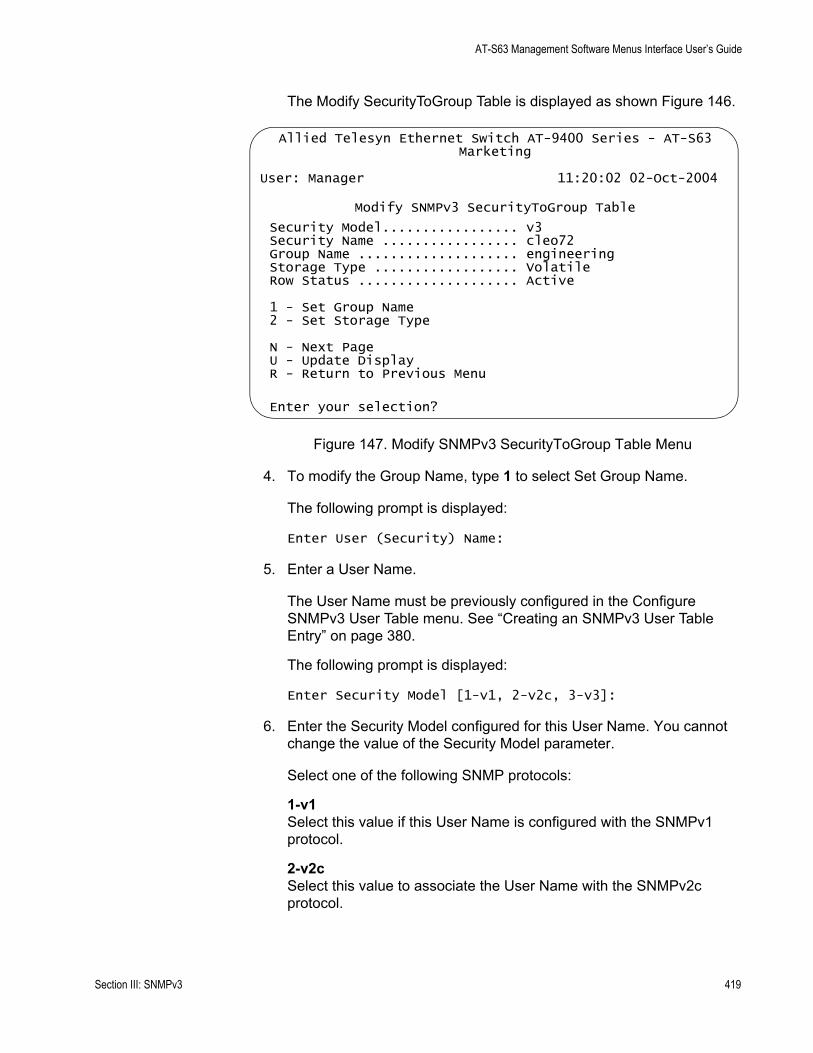
AT-S63 Management Software Menus Interface User’s Guide
The Modify SecurityToGroup Table is displayed as shown Figure 146.
Figure 147. Modify SNMPv3 SecurityToGroup Table Menu
4. To modify the Group Name, type 1 to select Set Group Name.
The following prompt is displayed:
Enter User (Security) Name:
5. Enter a User Name.
The User Name must be previously configured in the Configure SNMPv3 User Table menu. See “Creating an SNMPv3 User Table Entry” on page 380.
The following prompt is displayed:
Enter Security Model [1-v1, 2-v2c, 3-v3]:
6. Enter the Security Model configured for this User Name. You cannot change the value of the Security Model parameter.
Select one of the following SNMP protocols:
1-v1Select this value if this User Name is configured with the SNMPv1 protocol.
2-v2cSelect this value to associate the User Name with the SNMPv2c protocol.
Allied Telesyn Ethernet Switch AT-9400 Series - AT-S63Marketing
User: Manager 11:20:02 02-Oct-2004
Modify SNMPv3 SecurityToGroup Table
Security Model................. v3Security Name ................. cleo72Group Name .................... engineeringStorage Type .................. VolatileRow Status .................... Active
1 - Set Group Name2 - Set Storage Type
N - Next PageU - Update DisplayR - Return to Previous Menu
Enter your selection?
Section III: SNMPv3 419

Chapter 20: SNMPv3
3-v3Select this value to associate the User Name with the SNMPv3 protocol.
The following prompt is displayed:
Enter Group Name:
7. Enter the new Group Name.
This value must match a value configured in the Group Name parameter in the Configure SNMPv3 Access Table. See “Creating an SNMPv3 Access Table Entry” on page 399.
8. After making changes, type R until you return to the Main Menu. Then type S to select Save Configuration Changes.
Modifying the Storage Type
To modify the Storage Type in an SNMPv3 SecurityToGroup Table entry, perform the following procedure.
1. Follow steps 1 through 5 in the procedure described in “Creating an SNMPv3 User Table Entry” on page 380. Or, from the Main Menu type 5->1->1->8->5.
The Configure SNMPv3 Table menu is shown in Figure 139 on page 381.
2. From the Configure SNMPv3 Table menu, type 5 to select Configure SNMPv3 SecurityToGroup Table.
The Configure SNMPv3 SecurityToGroup Table is shown in Figure 144 on page 400.
3. From the Configure SNMPv3 SecurityToGroup Table, type 3 to select Modify SNMPv3 Table Entry.
4. To modify the storage type, type 2 to select Set Storage Type.
The following prompt is displayed:
Enter User (Security) Name:
5. Enter a User Name.
The User Name must be previously configured in the Configure SNMPv3 User Table menu. See “Creating an SNMPv3 User Table Entry” on page 380.
The following prompt is displayed:
Enter Security Model [1-v1, 2-v2c, 3-v3]:
420 Section III: SNMPv3
AT-S63 Management Software Menus Interface User’s Guide
6. Enter the Security Model configured for this User Name. You cannot change the value of the Security Model parameter.
Select one of the following SNMP protocols:
1-v1Select this value if this User Name is configured with the SNMPv1 protocol.
2-v2cSelect this value if this User Name is configured with the SNMPv2c protocol.
3-v3Select this value if this User Name is configured with the SNMPv3 protocol.
The following prompt is displayed:
Enter Storage Type [V-Volatile, N-NonVolatile]:
7. Select one of the following storage types for this table entry:
V - VolatileSelect this storage type if you do not want the ability to save an entry in the SNMPv3 SecurityToGroup Table to the configuration file. After making changes to an SNMPv3 SecurityToGroup Table entry with a Volatile storage type, the S - Save Configuration Changes option does not appear on the Main Menu.
N-NonVolatileSelect this storage type if you want the ability to save an entry in the SNMPv3 SecurityToGroup Table to the configuration file. After making changes to an SNMPv3 SecurityToGroup Table entry with a NonVolatile storage type, the S - Save Configuration Changes option appears on the Main Menu, allowing you to save your changes. Allied Telesyn recommends this storage type.
8. After making changes, type R until you return to the Main Menu. Then type S to select Save Configuration Changes.
Section III: SNMPv3 421
Chapter 20: SNMPv3
Configuring the SNMPv3 Notify Table
This section contains a description of the SNMPv3 Notify Table menu and how to create, delete, and modify table entries. The Configure SNMPv3 Notify Table menu allows you to define a name for sending traps. For each Notify Name, you define if a trap or inform message ia sent. The two message types, trap and inform, have different packet formats.
For each Notify group, you can configure:
Notify NameNotify Tag Notify TypeStorage Type
The value of the Notify Tag is linked with the Tag List parameter in the Configure SNMPv3 Target Address Table menu. As a result, the Notify Tag parameter assigns a Target IP address to the Notify Table internally.
There are three functions you can perform with the Configure SNMPv3 Notify Table menu.
“Creating an SNMPv3 Notify Table Entry,” next“Deleting an SNMPv3 Notify Table Entry” on page 424“Modifying an SNMPv3 Notify Table Entry” on page 425
Creating anSNMPv3 Notify
Table Entry
To create an entry in the SNMPv3 Notify Table menu, perform the following procedure.
1. Follow steps 1 through 5 in the procedure described in “Creating an SNMPv3 User Table Entry” on page 380. Or, from the Main menu type5->1->1->8->5.
The Configure SNMPv3 Table menu is shown in Figure 139 on page 381.
2. From the Configure SNMPv3 Table menu, type 6 to select Configure SNMPv3 Notify Table.
422 Section III: SNMPv3
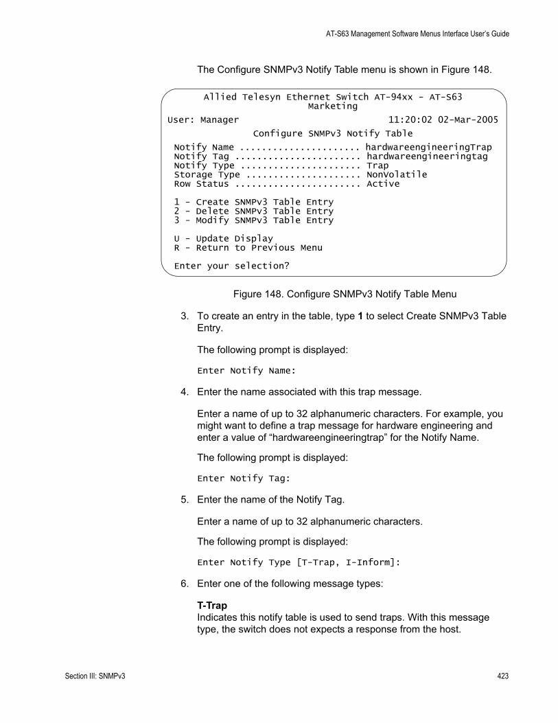
AT-S63 Management Software Menus Interface User’s Guide
The Configure SNMPv3 Notify Table menu is shown in Figure 148.
Figure 148. Configure SNMPv3 Notify Table Menu
3. To create an entry in the table, type 1 to select Create SNMPv3 Table Entry.
The following prompt is displayed:
Enter Notify Name:
4. Enter the name associated with this trap message.
Enter a name of up to 32 alphanumeric characters. For example, you might want to define a trap message for hardware engineering and enter a value of “hardwareengineeringtrap” for the Notify Name.
The following prompt is displayed:
Enter Notify Tag:
5. Enter the name of the Notify Tag.
Enter a name of up to 32 alphanumeric characters.
The following prompt is displayed:
Enter Notify Type [T-Trap, I-Inform]:
6. Enter one of the following message types:
T-TrapIndicates this notify table is used to send traps. With this message type, the switch does not expects a response from the host.
Allied Telesyn Ethernet Switch AT-94xx - AT-S63Marketing
User: Manager 11:20:02 02-Mar-2005
Configure SNMPv3 Notify Table
Notify Name ...................... hardwareengineeringTrapNotify Tag ....................... hardwareengineeringtagNotify Type ...................... TrapStorage Type ..................... NonVolatileRow Status ....................... Active
1 - Create SNMPv3 Table Entry2 - Delete SNMPv3 Table Entry3 - Modify SNMPv3 Table Entry
U - Update DisplayR - Return to Previous Menu
Enter your selection?
Section III: SNMPv3 423
Chapter 20: SNMPv3
I-InformIndicates this notify table is used to send inform messages. With this message type, the switch expects a response from the host.
The following prompt is displayed:
Enter Storage Type [V-Volatile, N-NonVolatile]:
7. Select one of the following storage types for this table entry:
V - VolatileSelect this storage type if you do not want the ability to save an entry in the SNMPv3 Notify Table to the configuration file. After making changes to an SNMPv3 Notify Table entry with a Volatile storage type, the S - Save Configuration Changes option does not appear on the Main Menu.
N-NonVolatileSelect this storage type if you want the ability to save an entry in the SNMPv3 Notify Table to the configuration file. After making changes to an SNMPv3 Notify Table entry with a NonVolatile storage type, the S - Save Configuration Changes option appears on the Main Menu, allowing you to save your changes. Allied Telesyn recommends this storage type.
NoteThe Row Status parameter is a read-only field. The Active value indicates the SNMPv3 Notify Table entry takes effect immediately.
8. After making changes, type R until you return to the Main Menu. Then type S to select Save Configuration Changes.
Deleting anSNMPv3 Notify
Table Entry
You may want to delete an entry from the Configure SNMPv3 Notify Table menu. When you delete a Configure SNMPv3 Notify Table entry, there is no way to undelete, or recover, the entry.
To delete an entry in the Configure SNMPv3 Notify Table menu, perform the following procedure:
1. Follow steps 1 through 5 in the procedure described in “Creating an SNMPv3 User Table Entry” on page 380. Or, from the Main menu type 5->1->1->8->5.
The Configure SNMPv3 Table menu is shown in Figure 139 on page 381.
2. From the Configure SNMPv3 Table menu, type 6 to select Configure SNMPv3 Notify Table.
424 Section III: SNMPv3
AT-S63 Management Software Menus Interface User’s Guide
The Configure SNMPv3 Notify Table menu is shown in Figure 148 on page 423.
NoteTo display a Group Name and its associated parameters from the Configure SNMPv3 SecurityToGroup Table menu, type N to display the Next Page and P to display the previous page.
3. To delete an SNMPv3 Notify Table entry, type 2 to select Delete SNMPv3 Table Entry.
The following prompt is displayed:
Enter Notify Name:
4. Enter a Notify Name.
The following prompt is displayed:
Do you want to delete this table entry? (Y/N):[Yes/No]->
5. Enter Y to delete the SNMPv3 Notify Table entry or N to save the entry.
6. After making changes, type R until you return to the Main Menu. Then type S to select Save Configuration Changes.
Modifying anSNMPv3 Notify
Table Entry
This section describes how to modify parameters in an SNMPv3 Notify Table entry. See the following procedures:
“Modifying a Notify Tag” on page 425“Modifying a Notify Type” on page 426“Modifying a Storage Type” on page 427
Modifying a Notify Tag
To modify the Notify Tag parameter in an SNMPv3 Notify Table entry, perform the following procedure.
1. Follow steps 1 through 5 in the procedure described in “Creating an SNMPv3 User Table Entry” on page 380. Or, from the Main Menu type 5->1->1->8->5.
The Configure SNMPv3 Table menu is shown in Figure 139 on page 381.
2. From the Configure SNMPv3 Table menu, type 6 to select Configure SNMPv3 Notify Table.
The Configure SNMPv3 Notify Table menu is shown in Figure 148 on page 423.
Section III: SNMPv3 425
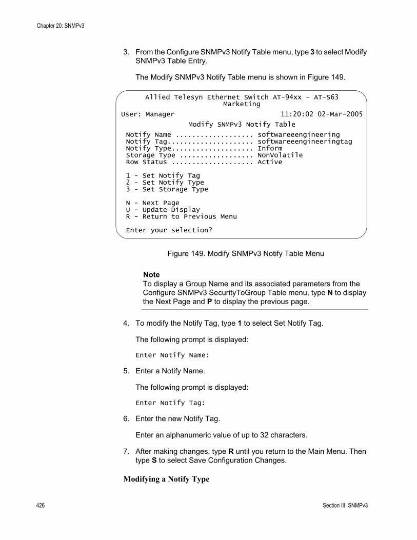
Chapter 20: SNMPv3
3. From the Configure SNMPv3 Notify Table menu, type 3 to select Modify SNMPv3 Table Entry.
The Modify SNMPv3 Notify Table menu is shown in Figure 149.
Figure 149. Modify SNMPv3 Notify Table Menu
NoteTo display a Group Name and its associated parameters from the Configure SNMPv3 SecurityToGroup Table menu, type N to display the Next Page and P to display the previous page.
4. To modify the Notify Tag, type 1 to select Set Notify Tag.
The following prompt is displayed:
Enter Notify Name:
5. Enter a Notify Name.
The following prompt is displayed:
Enter Notify Tag:
6. Enter the new Notify Tag.
Enter an alphanumeric value of up to 32 characters.
7. After making changes, type R until you return to the Main Menu. Then type S to select Save Configuration Changes.
Modifying a Notify Type
Allied Telesyn Ethernet Switch AT-94xx - AT-S63Marketing
User: Manager 11:20:02 02-Mar-2005
Modify SNMPv3 Notify Table
Notify Name ................... softwareeengineeringNotify Tag..................... softwareeengineeringtagNotify Type.................... InformStorage Type .................. NonVolatileRow Status .................... Active
1 - Set Notify Tag2 - Set Notify Type3 - Set Storage Type
N - Next PageU - Update DisplayR - Return to Previous Menu
Enter your selection?
426 Section III: SNMPv3
AT-S63 Management Software Menus Interface User’s Guide
To modify the Notify Type parameter in an SNMPv3 Notify Table entry, perform the following procedure.
1. Follow steps 1 through 5 in the procedure described in “Creating an SNMPv3 User Table Entry” on page 380. Or, from the Main Menu type 5->1->1->8->5.
The Configure SNMPv3 Table menu is shown in Figure 139 on page 381.
2. From the Configure SNMPv3 Table menu, type 6 to select Configure SNMPv3 Notify Table.
The Configure SNMPv3 Notify Table menu is shown in Figure 148 on page 423.
3. From the Configure SNMPv3 Notify Table menu, type 3 to select Modify SNMPv3 Table Entry.
The Modify SNMPv3 Notify Table is shown in Figure 149 on page 426.
4. To modify the Notify Type, type 2 to select Set Notify Type.
The following prompt is displayed:
Enter Notify Name:
5. Enter a Notify Name.
The following prompt is displayed:
Enter Notify Type [T-Trap, I-Inform]:
6. Enter one of the following message types:
T-TrapIndicates this notify table is used to send traps. With this message type, the switch does not expect a response from the host.
I-InformIndicates this notify table is used to send inform messages. With this message type, the switch expects a response from the host.
7. After making changes, type R until you return to the Main Menu. Then type S to select Save Configuration Changes.
Modifying a Storage Type
To modify the Storage Type parameter in an SNMPv3 Notify Table entry, perform the following procedure.
Section III: SNMPv3 427
Chapter 20: SNMPv3
1. Follow steps 1 through 5 in the procedure described in “Creating an SNMPv3 User Table Entry” on page 380. Or, from the Main Menu type 5->1->1->8->5.
The Configure SNMPv3 Table menu is shown in Figure 139 on page 381.
2. From the Configure SNMPv3 Table menu, type 6 to select Configure SNMPv3 Notify Table.
The Configure SNMPv3 Notify Table menu is shown in Figure 148 on page 423.
3. From the Configure SNMPv3 Notify Table menu, type 3 to select Modify SNMPv3 Table Entry.
The Modify SNMPv3 Notify Table is shown in Figure 149 on page 426.
4. To modify the Storage Type, type 3 to select Set Storage Type.
The following prompt is displayed:
Enter Notify Name:
5. Enter a Notify Name.
The following prompt is displayed:
Enter Storage type [V-Volatile, N-NonVolatile]:
6. Select one of the following storage types for this table entry:
V - VolatileSelect this storage type if you do not want the ability to save an entry in the SNMPv3 Notify Table to the configuration file. After making changes to an SNMPv3 Notify Table entry with a Volatile storage type, the S - Save Configuration Changes option does not appear on the Main Menu.
N-NonVolatileSelect this storage type if you want the ability to save an entry in the SNMPv3 Notify Table to the configuration file. After making changes to an SNMPv3 Notify Table entry with a NonVolatile storage type, the S - Save Configuration Changes option appears on the Main Menu, allowing you to save your changes. Allied Telesyn recommends this storage type.
7. After making changes, type R until you return to the Main Menu. Then type S to select Save Configuration Changes.
428 Section III: SNMPv3
AT-S63 Management Software Menus Interface User’s Guide
Configuring the SNMPv3 Target Address Table
This section contains a description of the SNMPv3 Target Address Table menu and how to create, delete, and modify table entries. You use the SNMPv3 Target Address Table menu to assign the IP address of a host that is used for generating notifications. The Configure SNMPv3 Target Address Table menu is linked internally to the Configure SNMPv3 Notify Table through the Tag List parameter. The Configure SNMPv3 Notify Table menu receives the host IP address through the configuration of the SNMPv3 Target Address Table menu.
For each Target Address Table entry, you can configure the following parameters:
Target Address NameTarget IP AddressUDP PortTimeout ValueNumber of RetriesTag ListTarget ParametersStorage Type
The values for the Tag List parameter are configured with the Notify Tag parameter in the Configure SNMPv3 Notify Table. See “Creating an SNMPv3 Notify Table Entry” on page 422.
There are three functions you can perform with the Configure SNMPv3 Target Address Table menu.
“Creating an SNMPv3 Target Address Table Entry,” next“Deleting an SNMPv3 Target Address Table Entry” on page 432“Modifying an SNMPv3 Target Address Table Entry” on page 433
Creating anSNMPv3 Target
Address TableEntry
To create an entry in the Configure SNMPv3 Target Address Table menu, perform the following procedure.
1. Follow steps 1 through 5 in the procedure described in “Creating an SNMPv3 User Table Entry” on page 380. Or, from the Main Menu type 5->1->1->8->5.
The Configure SNMPv3 Table menu is shown in Figure 139 on page 381.
2. From the Configure SNMPv3 Table menu, type 7 to select Configure SNMPv3 Target Address Table.
Section III: SNMPv3 429
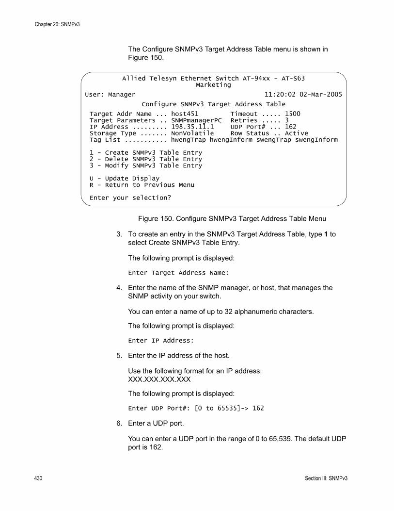
Chapter 20: SNMPv3
The Configure SNMPv3 Target Address Table menu is shown in Figure 150.
Figure 150. Configure SNMPv3 Target Address Table Menu
3. To create an entry in the SNMPv3 Target Address Table, type 1 to select Create SNMPv3 Table Entry.
The following prompt is displayed:
Enter Target Address Name:
4. Enter the name of the SNMP manager, or host, that manages the SNMP activity on your switch.
You can enter a name of up to 32 alphanumeric characters.
The following prompt is displayed:
Enter IP Address:
5. Enter the IP address of the host.
Use the following format for an IP address:XXX.XXX.XXX.XXX
The following prompt is displayed:
Enter UDP Port#: [0 to 65535]-> 162
6. Enter a UDP port.
You can enter a UDP port in the range of 0 to 65,535. The default UDP port is 162.
Allied Telesyn Ethernet Switch AT-94xx - AT-S63Marketing
User: Manager 11:20:02 02-Mar-2005
Configure SNMPv3 Target Address Table
Target Addr Name ... host451 Timeout ..... 1500Target Parameters .. SNMPmanagerPC Retries ..... 3IP Address ......... 198.35.11.1 UDP Port# ... 162Storage Type ....... NonVolatile Row Status .. ActiveTag List ........... hwengTrap hwengInform swengTrap swengInform
1 - Create SNMPv3 Table Entry2 - Delete SNMPv3 Table Entry3 - Modify SNMPv3 Table Entry
U - Update DisplayR - Return to Previous Menu
Enter your selection?
430 Section III: SNMPv3

AT-S63 Management Software Menus Interface User’s Guide
The following prompt is displayed:
Enter Timeout (10mS): [0 to 2147483647]-> 1500
7. Enter a timeout value in milliseconds.
When an Inform message is generated, a response from the switch is required. The timeout value determines how long the switch considers the Inform message an active message. This parameter applies to Inform messages only. The range is from 0 to 2,147,483,647 milliseconds. The default value is 1500 milliseconds.
The following prompt is displayed:
Enter Retries:[0 to 255]-> 3
8. Enter the number of times the switch will retry, or resend, an Inform message.
When an Inform message is generated, a response from the switch is required. This parameter determines how many times the switch resends an Inform message. The Retries parameter applies to Inform messages only. The range is 0 to 255 retries. The default is 3 retries.
The following prompt is displayed:
Enter Tag List:
9. Enter a Tag List.
This list consists of a tag or list of tags you configured in a Configure SNMPv3 Notify Table entry with the Notify Tag parameter. See “Creating an SNMPv3 Notify Table Entry” on page 422. Enter a Tag List of up to 256 alphanumeric characters. Use a space to separate entries, for example:
hwengtag swengtag testengtag
The following prompt is displayed:
Enter Target Parameters:
10. Enter a Target Parameters name.
This name can consist of up to 32 alphanumeric characters. The value configured here must match the value configured with the Target Parameters Name parameter in the Configure SNMPv3 Target Parameters Table.
The following prompt is displayed:
Enter Storage Type [V-Volatile, N-NonVolatile]:
11. Select one of the following storage types for this table entry:
Section III: SNMPv3 431
Chapter 20: SNMPv3
V - VolatileSelect this storage type if you do not want the ability to save an entry in the SNMPv3 Target Address Table to the configuration file. After making changes to an SNMPv3 Target Address Table entry with a Volatile storage type, the S - Save Configuration Changes option does not appear on the Main Menu.
N-NonVolatileSelect this storage type if you want the ability to save an entry in the SNMPv3 Target Address Table to the configuration file. After making changes to an SNMPv3 Target Address entry with a NonVolatile storage type, the S - Save Configuration Changes option appears on the Main Menu, allowing you to save your changes. Allied Telesyn recommends this storage type.
NoteThe Row Status parameter is a read-only field. The Active value indicates the SNMPv3 Target Address Table entry will take effect immediately.
12. After making changes, type R until you return to the Main Menu. Then type S to select Save Configuration Changes.
Deleting anSNMPv3 Target
Address TableEntry
You may want to delete an entry from the SNMPv3 Target Address Table. After you delete an SNMPv3 Target Address Table entry, there is no way to undelete, or recover, the entry.
To delete an entry in the SNMPv3 Target Address Table, perform the following procedure:
1. Follow steps 1 through 5 in the procedure described in “Creating an SNMPv3 User Table Entry” on page 380. Or, from the Main Menu type 5->1->1->8->5.
The Configure SNMPv3 Table menu is shown in Figure 139 on page 381.
2. From the Configure SNMPv3 Table menu, type 7 to select Configure SNMPv3 Target Address Table.
The Configure SNMPv3 Target Address Table menu is shown in Figure 152 on page 443.
NoteTo display a Group Name and its associated parameters from the Configure SNMPv3 SecurityToGroup Table menu, type N to display the Next Page and P to display the previous page.
432 Section III: SNMPv3
AT-S63 Management Software Menus Interface User’s Guide
3. To delete an SNMPv3 Target Address Table entry, type 2 to select Delete SNMPv3 Table Entry.
The following prompt is displayed:
Enter Target Address Name:
4. Enter a Target Address Name.
The following prompt is displayed:
Do you want to delete this table entry?(Y/N):[Yes/No]->
5. Enter Y to delete the SNMPv3 Target Address Table entry or N to save the entry.
6. After making changes, type R until you return to the Main Menu. Then type S to select Save Configuration Changes.
Modifying anSNMPv3 Target
Address TableEntry
This section describes how to modify parameters in an SNMPv3 Target Address Table entry. See the following procedures:
“Modifying a Target IP Address” on page 433“Modifying the Target Address UDP Port” on page 435“Modifying the Target Address Timeout” on page 436“Modifying the Target Address Retries” on page 437“Modifying the Target Address Tag List” on page 438“Modifying the Target Parameters Field” on page 439“Modifying the Storage Type” on page 440
NoteYou cannot modify the Target Address Name parameter.
Modifying a Target IP Address
To modify the target IP address in an SNMPv3 Target Address Table entry, perform the following procedure.
1. Follow steps 1 through 5 in the procedure described in “Creating an SNMPv3 User Table Entry” on page 380. Or, from the Main Menu type 5->1->1->8->5.
The Configure SNMPv3 Table menu is shown in Figure 139 on page 381.
2. From the Configure SNMPv3 Table menu, type 7 to select Configure SNMPv3 Target Address Table.
Section III: SNMPv3 433
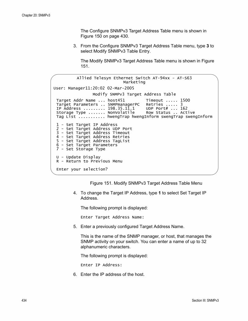
Chapter 20: SNMPv3
The Configure SNMPv3 Target Address Table menu is shown in Figure 150 on page 430.
3. From the Configure SNMPv3 Target Address Table menu, type 3 to select Modify SNMPv3 Table Entry.
The Modify SNMPv3 Target Address Table menu is shown in Figure 151.
Figure 151. Modify SNMPv3 Target Address Table Menu
4. To change the Target IP Address, type 1 to select Set Target IP Address.
The following prompt is displayed:
Enter Target Address Name:
5. Enter a previously configured Target Address Name.
This is the name of the SNMP manager, or host, that manages the SNMP activity on your switch. You can enter a name of up to 32 alphanumeric characters.
The following prompt is displayed:
Enter IP Address:
6. Enter the IP address of the host.
Allied Telesyn Ethernet Switch AT-94xx - AT-S63Marketing
User: Manager11:20:02 02-Mar-2005
Modify SNMPv3 Target Address Table
Target Addr Name ... host451 Timeout ..... 1500Target Parameters .. SNMPmanagerPC Retries ..... 3IP Address ......... 198.35.11.1 UDP Port# ... 162Storage Type ....... NonVolatile Row Status .. ActiveTag List ........... hwengTrap hwengInform swengTrap swengInform
1 - Set Target IP Address2 - Set Target Address UDP Port3 - Set Target Address Timeout4 - Set Target Address Retries5 - Set Target Address TagList6 - Set Target Parameters7 - Set Storage Type
U - Update DisplayR - Return to Previous Menu
Enter your selection?
434 Section III: SNMPv3
AT-S63 Management Software Menus Interface User’s Guide
Use the following format for an IP address:XXX.XXX.XXX.XXX
7. After making changes, type R until you return to the Main Menu. Then type S to select Save Configuration Changes.
Modifying the Target Address UDP Port
To modify the Target Address UDP Port parameter in an SNMPv3 Target Address Table entry, perform the following procedure:
1. Follow steps 1 through 5 in the procedure described in “Creating an SNMPv3 User Table Entry” on page 380. Or, from the Main Menu type 5->1->1->8->5.
The Configure SNMPv3 Table menu is shown in Figure 139 on page 381.
2. From the Configure SNMPv3 Table menu, type 7 to select Configure SNMPv3 Target Address Table.
The Configure SNMPv3 Target Address Table menu is shown in Figure 150 on page 430.
3. From the Configure SNMPv3 Target Address Table menu, type 3 to select Modify SNMPv3 Table Entry.
The Modify SNMPv3 Target Address Table menu is shown in Figure 151 on page 434.
4. To change the Target Address UDP Port, type 2 to select Set Target Address UDP Port.
The following prompt is displayed:
Enter Target Address Name:
5. Enter a previously configured Target Address Name.
This is the name of the SNMP manager, or host, that manages the SNMP activity on your switch. You can enter a name of up to 32 alphanumeric characters.
The following prompt is displayed:
Enter UDP Port#: [0 to 65535]-> 162
6. Enter a UDP port.
You can enter a UDP port in the range of 0 to 65,535. The default UDP port is 162.
Section III: SNMPv3 435
Chapter 20: SNMPv3
7. After making changes, type R until you return to the Main Menu. Then type S to select Save Configuration Changes.
Modifying the Target Address Timeout
The Target Address Timeout parameter only applies when the message type is an Inform message. To modify the Target Address Timeout parameter in an SNMPv3 Target Address Table entry, perform the following procedure.
1. Follow steps 1 through 5 in the procedure described in “Creating an SNMPv3 User Table Entry” on page 380. Or, from the Main Menu type 5->1->1->8->5.
The Configure SNMPv3 Table menu is shown in Figure 139 on page 381.
2. From the Configure SNMPv3 Table menu, type 7 to select Configure SNMPv3 Target Address Table.
The Configure SNMPv3 Target Address Table menu is shown in Figure 150 on page 430.
3. From the Configure SNMPv3 Target Address Table menu, type 3 to select Modify SNMPv3 Table Entry.
The Modify SNMPv3 Target Address Table menu is shown in Figure 151 on page 434.
4. To modify the Target Address Timeout, type 3 to select Set Target Address Timeout.
The following prompt is displayed:
Enter Target Address Name:
5. Enter a previously configured Target Address Name.
This is the name of the SNMP manager, or host, that manages the SNMP activity on your switch. You can enter a name of up to 32 alphanumeric characters.
The following prompt is displayed:
Enter Timeout (10mS): [0 to 2147483647]-> 1500
6. Enter a timeout value in milliseconds.
When an Inform message is generated, a response from the switch is required. The timeout value determines how long the switch considers the Inform message an active message. This parameter applies to
436 Section III: SNMPv3
AT-S63 Management Software Menus Interface User’s Guide
Inform messages only. The range is from 0 to 2,147,483,647 milliseconds. The default value is 1500 milliseconds.
7. After making changes, type R until you return to the Main Menu. Then type S to select Save Configuration Changes.
Modifying the Target Address Retries
The Target Address Retries parameter only applies when the message type is an Inform message. To modify the Target Address Retries parameter in an SNMPv3 Target Address Table entry, perform the following procedure.
1. Follow steps 1 through 5 in the procedure described in “Creating an SNMPv3 User Table Entry” on page 380. Or, from the Main Menu type 5->1->1->8->5.
The Configure SNMPv3 Table menu is shown in Figure 139 on page 381.
2. From the Configure SNMPv3 Table menu, type 7 to select Configure SNMPv3 Target Address Table.
The Configure SNMPv3 Target Address Table menu is shown in Figure 150 on page 430.
3. From the Configure SNMPv3 Target Address Table menu, type 3 to select Modify SNMPv3 Table Entry.
The Modify SNMPv3 Target Address Table menu is shown in Figure 151 on page 434.
4. To modify the Target Address Retries, type 4 to select Set Target Address Retries.
The following prompt is displayed:
Enter Target Address Name:
5. Enter a previously configured Target Address Name.
This is the name of the SNMP manager, or host, that manages the SNMP activity on your switch. You can enter a name of up to 32 alphanumeric characters.
The following prompt is displayed:
Enter Retries:[0 to 255]-> 3
6. Enter the number of times the switch will retry, or resend, the Inform message.
Section III: SNMPv3 437
Chapter 20: SNMPv3
The range is 0 to 255 retries. The default is 3 retries.
7. After making changes, type R until you return to the Main Menu. Then type S to select Save Configuration Changes.
Modifying the Target Address Tag List
To modify the Target Address Tag List parameter in an SNMPv3 Target Address Table entry, perform the following procedure.
1. Follow steps 1 through 5 in the procedure described in “Creating an SNMPv3 User Table Entry” on page 380. Or, from the Main Menu type 5->1->1->8->5.
The Configure SNMPv3 Table menu is shown in Figure 139 on page 381.
2. From the Configure SNMPv3 Table menu, type 7 to select Configure SNMPv3 Target Address Table.
The Configure SNMPv3 Target Address Table menu is shown in Figure 150 on page 430.
3. From the Configure SNMPv3 Target Address Table menu, type 3 to select Modify SNMPv3 Table Entry.
The Modify SNMPv3 Target Address Table menu is shown in Figure 151 on page 434.
4. To modify the Target Address Tag List, type 5 to select Set Target Address TagList.
The following prompt is displayed:
Enter Target Address Name:
5. Enter a previously configured Target Address Name.
This is the name of the SNMP manager, or host, that manages the SNMP activity on your switch. You can enter a name of up to 32 alphanumeric characters.
The following prompt is displayed:
Enter Tag List:
Enter a Tag List of up to 256 alphanumeric characters. Use a space to separate entries. This list consists of a tag or list of tags you configured in a Configure SNMPv3 Notify Table entry with the Notify Tag parameter. See “Creating an SNMPv3 Notify Table Entry” on page 422.
438 Section III: SNMPv3

AT-S63 Management Software Menus Interface User’s Guide
6. After making changes, type R until you return to the Main Menu. Then type S to select Save Configuration Changes.
Modifying the Target Parameters Field
To modify the Target Parameters field in an SNMPv3 Target Address Table entry, perform the following procedure.
1. Follow steps 1 through 5 in the procedure described in “Creating an SNMPv3 User Table Entry” on page 380. Or, from the Main Menu type 5->1->1->8->5.
The Configure SNMPv3 Table menu is shown in Figure 139 on page 381.
2. From the Configure SNMPv3 Table menu, type 7 to select Configure SNMPv3 Target Address Table.
The Configure SNMPv3 Target Address Table menu is shown in Figure 150 on page 430.
3. From the Configure SNMPv3 Target Address Table menu, type 3 to select Modify SNMPv3 Table Entry.
The Modify SNMPv3 Target Address Table menu is shown in Figure 151 on page 434.
4. To modify the Target Parameters field, type 6 to select Set Target Parameters.
The following prompt is displayed:
Enter Target Address Name:
5. Enter a previously configured Target Address Name.
This is the name of the SNMP manager, or host, that manages the SNMP activity on your switch. You can enter a name of up to 32 alphanumeric characters.
The following prompt is displayed:
Enter Target Parameters:
6. Enter a Target Parameters Name.
The value configured here must match the value configured with the Target Parameters Name parameter in the Configure SNMPv3 Target Parameters Table. This name can consist of up to 32 alphanumeric characters.
Section III: SNMPv3 439

Chapter 20: SNMPv3
7. After making changes, type R until you return to the Main Menu. Then type S to select Save Configuration Changes.
Modifying the Storage Type
To modify the Storage Type parameter in an SNMPv3 Target Address Table entry, perform the following procedure.
1. Follow steps 1 through 5 in the procedure described in “Creating an SNMPv3 User Table Entry” on page 380. Or, from the Main Menu type 5->1->1->8->5.
The Configure SNMPv3 Table menu is shown in Figure 139 on page 381.
2. From the Configure SNMPv3 Table menu, type 7 to select Configure SNMPv3 Target Address Table.
The Configure SNMPv3 Target Address Table menu is shown in Figure 150 on page 430.
3. From the Configure SNMPv3 Target Address Table menu, type 3 to select Modify SNMPv3 Table Entry.
The Modify SNMPv3 Target Address Table menu is shown in Figure 151 on page 434.
4. To modify the Storage Type, type 7 to select Set Storage Type.
The following prompt is displayed:
Enter Target Address Name:
5. Enter a previously configured Target Address Name.
This is the name of the SNMP manager, or host, that manages the SNMP activity on your switch. You can enter a name of up to 32 alphanumeric characters.
The following prompt is displayed:
Enter Storage Type [V-Volatile, N-NonVolatile]:
6. Select one of the following storage types for this table entry:
V - VolatileSelect this storage type if you do not want the ability to save an entry in the SNMPv3 Target Address Table to the configuration file. After making changes to an SNMPv3 Target Address Table entry with a Volatile storage type, the S - Save Configuration Changes option does not appear on the Main Menu.
440 Section III: SNMPv3
AT-S63 Management Software Menus Interface User’s Guide
N-NonVolatileSelect this storage type if you want the ability to save an entry in the SNMPv3 Target Address Table to the configuration file. After making changes to an SNMPv3 Target Address entry with a NonVolatile storage type, the S - Save Configuration Changes option appears on the Main Menu, allowing you to save your changes. Allied Telesyn recommends this storage type.
7. After making changes, type R until you return to the Main Menu. Then type S to select Save Configuration Changes.
Section III: SNMPv3 441

Chapter 20: SNMPv3
Configuring the SNMPv3 Target Parameters Table
This section contains a description of the SNMPv3 Target Parameters Table and how to create, delete, and modify table entries. The SNMPv3 Target Parameters Table links the user security information with the message notification information configured in the Configure SNMPv3 Notify Table menu and Configure SNMPv3 Target Address Table menu.
In the SNMPv3 Target Parameters Table, you specify the SNMP parameters that are used when a message is generated to a target, or host, IP address. The SNMPv3 Target Parameters Table also links a User Name and its related security information, called user security information, with a host. The user security information consists of the following parameters listed in the SNMPv3 tables where they are configured:
User Name parameter configured in the SNMPv3 User Table menuView Name parameter configured in the SNMPv3 View Table menuGroup Name, Security Model, and Security Level parameters configured in the SNMPv3 Access TableUser Name, Security Model, and Group Name configured in the SNMPv3 SecurityToGroup Table
When you enter user security information in an SNMPv3 Target Parameters Table entry, the information must match the configuration in the SNMPv3 tables listed above. If the user security information in the SNMPv3 Target Parameters Table entry does not match the configuration in the tables listed above, messages are not sent on behalf of the user.
NoteIn the SNMPv3 Target Parameters Table, the Security Name parameter is the equivalent to the User Name parameter in the SNMPv3 User Table.
For each Target Address Table entry, you can configure:
Target Parameters NameSecurity Name (User Name)Security ModelSecurity LevelStorage Type
There are three functions you can perform with the Configure SNMPv3 Target Parameters Table menu.
“Creating an SNMPv3 Target Parameters Table Entry,” next
442 Section III: SNMPv3
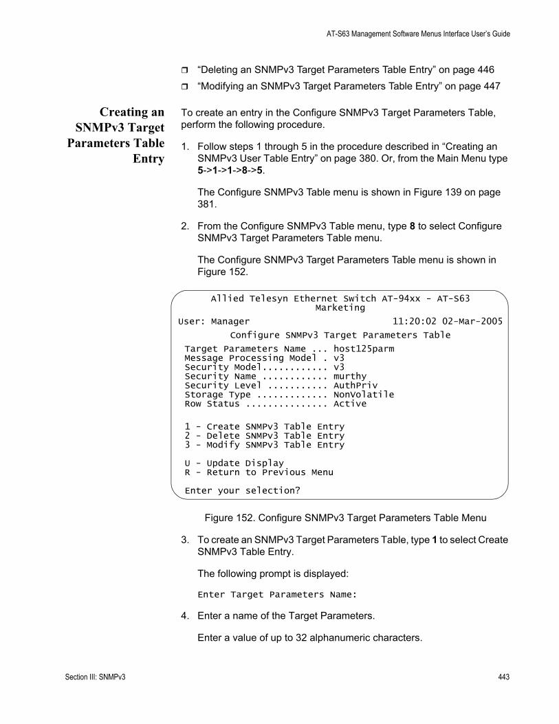
AT-S63 Management Software Menus Interface User’s Guide
“Deleting an SNMPv3 Target Parameters Table Entry” on page 446“Modifying an SNMPv3 Target Parameters Table Entry” on page 447
Creating anSNMPv3 Target
Parameters TableEntry
To create an entry in the Configure SNMPv3 Target Parameters Table, perform the following procedure.
1. Follow steps 1 through 5 in the procedure described in “Creating an SNMPv3 User Table Entry” on page 380. Or, from the Main Menu type 5->1->1->8->5.
The Configure SNMPv3 Table menu is shown in Figure 139 on page 381.
2. From the Configure SNMPv3 Table menu, type 8 to select Configure SNMPv3 Target Parameters Table menu.
The Configure SNMPv3 Target Parameters Table menu is shown in Figure 152.
Figure 152. Configure SNMPv3 Target Parameters Table Menu
3. To create an SNMPv3 Target Parameters Table, type 1 to select Create SNMPv3 Table Entry.
The following prompt is displayed:
Enter Target Parameters Name:
4. Enter a name of the Target Parameters.
Enter a value of up to 32 alphanumeric characters.
Allied Telesyn Ethernet Switch AT-94xx - AT-S63Marketing
User: Manager 11:20:02 02-Mar-2005
Configure SNMPv3 Target Parameters Table
Target Parameters Name ... host125parmMessage Processing Model . v3Security Model............ v3Security Name ............ murthySecurity Level ........... AuthPrivStorage Type ............. NonVolatileRow Status ............... Active
1 - Create SNMPv3 Table Entry 2 - Delete SNMPv3 Table Entry3 - Modify SNMPv3 Table Entry
U - Update DisplayR - Return to Previous Menu
Enter your selection?
Section III: SNMPv3 443

Chapter 20: SNMPv3
NoteYou are prompted to enter a value for the Message Processing Model parameter only if you select SNMPv1 or SNMPv2c as the Security Model. If you select the SNMPv3 protocol as the Security Model, then the Message Processing Model is automatically assigned to SNMPv3.
The following prompt is displayed:
Enter User (Security) Name:
5. Enter a User Name.
The value of this parameter is previously configured with the Configure SNMPv3 User Table. See “Creating an SNMPv3 User Table Entry” on page 380.
The following prompt is displayed:
Enter Security Model [1-v1, 2-v2c, 3-v3]:
6. Select one of the following SNMP protocols as the Security Model for this Security Name, or User Name.
1-v1Select this value to associate the Security Name, or User Name, with the SNMPv1 protocol.
2-v2cSelect this value to associate the Security Name, or User Name, with the SNMPv2c protocol.
3-v3Select this value to associate the Security Name, or User Name, with the SNMPv3 protocol. The SNMPv3 protocol allows you to configure the group to authenticate SNMPv3 entities (users) and to encrypt messages.
The following prompt is displayed:
Enter Security Level [N-NoAuthNoPriv, A-AuthNoPriv, P-AuthPriv]:
7. Select one of the following Security Levels:
NoteThe value you configure for the Security Level must match the value configured for the User Name in the Configure SNMPv3 User Table menu. See “Creating an SNMPv3 User Table Entry” on page 380.
444 Section III: SNMPv3
AT-S63 Management Software Menus Interface User’s Guide
N-NoAuthNoPrivThis option represents no authentication and no privacy protocol. Select this security level if you do not want to authenticate SNMP entities and you do not want to encrypt messages using a privacy protocol. This security level provides the least security.
NoteIf you have selected SNMPv1 or SNMPv2c, N-NoAuthNoPriv is the only security level you can select.
A-AuthNoPrivThis option represents authentication, but no privacy protocol. Select this security level if you want to authenticate SNMP users, but you do not want to encrypt messages using a privacy protocol.You can select this value if you configured the Security Model parameter with the SNMPv3 protocol.
P-AuthPrivThis option represents authentication and the privacy protocol. Select this security level to encrypt messages using a privacy protocol and authenticate SNMP entities. This level provides the greatest level of security. You can select this value if you configured the Security Model parameter with the SNMPv3 protocol.
The following prompt is displayed:
Enter Storage Type [V-Volatile, N-NonVolatile]:
8. Select one of the following storage types for this table entry:
V - VolatileSelect this storage type if you do not want the ability to save an entry in the SNMPv3 Target Parameters Table to the configuration file. After making changes to an SNMPv3 Target Parameters Table entry with a Volatile storage type, the S - Save Configuration Changes option does not appear on the Main Menu.
N-NonVolatileSelect this storage type if you want the ability to save an entry in the SNMPv3 Target Parameters Table to the configuration file. After making changes to an SNMPv3 Target Parameters Table entry with a NonVolatile storage type, the S - Save Configuration Changes option appears on the Main Menu, allowing you to save your changes. Allied Telesyn recommends this storage type.
NoteThe Row Status parameter is a read-only field. The Active value indicates the SNMPv3 Target Parameters Table entry will take effect immediately.
Section III: SNMPv3 445

Chapter 20: SNMPv3
9. After making changes, type R until you return to the Main Menu. Then type S to select Save Configuration Changes.
Deleting anSNMPv3 Target
Parameters TableEntry
You may want to delete an entry from the SNMPv3 Target Parameters Table. When you delete an SNMPv3 Target Parameters Table entry, there is no way to undelete, or recover, the entry.
To delete an entry in the SNMPv3 Target Parameters Table, perform the following procedure:
1. Follow steps 1 through 5 in the procedure described in “Creating an SNMPv3 User Table Entry” on page 380. Or, from the Main Menu type 5->1->1->8->5.
The Configure SNMPv3 Table menu is shown in Figure 139 on page 381.
2. From the Configure SNMPv3 Table menu, type 8 to select Configure SNMPv3 Target Parameters Table.
The Configure SNMPv3 Parameters Table menu is shown in Figure 152 on page 443.
NoteTo display a Group Name and its associated parameters from the Configure SNMPv3 SecurityToGroup Table menu, type N to display the Next Page and P to display the previous page.
3. To delete an SNMPv3 Target Parameters Table entry, type 2 to select Delete SNMPv3 Table Entry.
The following prompt is displayed:
Enter Target Parameters Name:
4. Enter a Target Parameters Name.
The following prompt is displayed:
Do you want to delete this table entry?(Y/N):[Yes/No]->
5. Enter Y to delete the SNMPv3 Target Address Table entry or N to save the entry.
6. After making changes, type R until you return to the Main Menu. Then type S to select Save Configuration Changes.
446 Section III: SNMPv3
AT-S63 Management Software Menus Interface User’s Guide
Modifying anSNMPv3 Target
Parameters TableEntry
This section provides procedures for modifying parameters in an SNMPv3 Target Parameters Table entry. The parameter values configured in the Target Parameters Table must match those configured in the other tables. For a more detailed explanation, see “Creating an SNMPv3 Target Parameters Table Entry” on page 443.
In an SNMPv3 Target Parameters Table entry, the Security Name parameter is linked to the User Name parameter on the SNMPv3 User Table. In an SNMPv3 User Table entry, the User Name parameter is used as an index for the entry. Because the User Name and Security Name parameters are linked, the information you configure that relates to a User Table entry must match the information you configure in the SNMPv3 Target Parameters Table entry. In addition, the values configured for the following parameters in an SNMPv3 Target Parameters Table entry must match those configured in the corresponding table entry:
User Name parameter in the SNMPv3 User Table View Name parameter in the SNMPv3 View Table Group Name, Security Model, and Security Level parameters in the SNMPv3 Access Table User Name, Security Model, Group Name parameters in the SNMPv3 SecurityToGroup Table
See the following procedures:
“Modifying the Security Name (User Name)” on page 447“Modifying the Security Model” on page 449“Modifying the Security Level” on page 450“Modifying the Message Process Model” on page 452“Modifying the Storage Type” on page 453
NoteYou cannot modify the Target Params Name parameter.
NoteYou cannot modify an entry in the SNMPv3 Target Parameter Table that contains a value of “default” in the Target Parameters Name field.
Modifying the Security Name (User Name)
In the AT-S63 implementation of the SNMPv3 protocol, the Security Name and the User Name parameters are equivalent. In the SNMPv3 Target Parameters Table menu, the Security Name and the User Name parameters are used interchangeably.
Section III: SNMPv3 447

Chapter 20: SNMPv3
When you modify the Security Name parameter, you must use a value that you configured with the User Name parameter in the Configure SNMPv3 User Table menu. If you do not use a value configured with the User Name parameter, messages are not sent on behalf of this User Name. See “Creating an SNMPv3 User Table Entry” on page 380.
To modify the Security Name parameter in an SNMPv3 Target Parameter Table entry, perform the following procedure.
1. Follow steps 1 through 5 in the procedure described in “Creating an SNMPv3 User Table Entry” on page 380. Or, from the Main Menu type 5->1->1->8->5.
The Configure SNMPv3 Table menu is shown in Figure 139 on page 381.
2. From the Configure SNMPv3 Table menu, type 8 to select Configure SNMPv3 Target Address Table.
The Configure SNMPv3 Target Parameters Table menu is shown in Figure 152.
3. From the Configure SNMPv3 Target Parameters Table menu, type 3 to select Modify SNMPv3 Table Entry.
The Modify SNMPv3 Target Parameters Table menu is shown in Figure 153.
Figure 153. Modify SNMPv3 Target Parameters Table Menu
Allied Telesyn Ethernet Switch AT-94xx - AT-S63Marketing
User: Manager 11:20:02 02-Mar-2005
Modify SNMPv3 Target Parameters Table
Target Parameters Name ... host27Message Processing Model . v3Security Model............ v3Security Name ............ hoaSecurity Level ........... AuthNoPrivStorage Type ............. NonVolatileRow Status ............... Active
1 - Set Security Name2 - Set Security Model3 - Set Security Level4 - Set Message Processing Model5 - Set Storage Type
U - Update DisplayR - Return to Previous Menu
Enter your selection?
448 Section III: SNMPv3
AT-S63 Management Software Menus Interface User’s Guide
4. To change the Security Name parameter, type 1 to select Set Security Name.
The following prompt is displayed:
Enter Target Parameters Name:
5. Enter a previously configured Target Parameters Name.
Enter a value of up to 32 alphanumeric characters.
The following prompt is displayed:
Enter User (Security) Name:
6. Enter a User Name.
Enter a value that you previously configured with the Configure SNMPv3 User Table menu. You can enter a value of up to 32 alphanumeric characters.
7. After making changes, type R until you return to the Main Menu. Then type S to select Save Configuration Changes.
Modifying the Security Model
For the Security or User Name you have selected, the value of the Security Model parameter in an SNMPv3 Target Parameter Table entry must match the value of the Security Model parameter in the SNMPv3 Access Table entry.
CautionIf the values of the Security Model parameter in the SNMPv3 User Table and the SNMPv3 Target Parameter Table entry do not match, notification messages are not generated on behalf of this User (Security) Name.
To modify the Security Model parameter in an SNMPv3 Target Parameter Table entry, perform the following procedure.
1. Follow steps 1 through 5 in the procedure described in “Creating an SNMPv3 User Table Entry” on page 380. Or, from the Main Menu type 5->1->1->8->5.
The Configure SNMPv3 Table menu is shown in Figure 139 on page 381.
2. From the Configure SNMPv3 Table menu, type 8 to select Configure SNMPv3 Target Address Table.
Section III: SNMPv3 449
Chapter 20: SNMPv3
The Configure SNMPv3 Target Parameters Table menu is shown in Figure 152.
3. From the Configure SNMPv3 Target Parameters Table menu, type 3 to select Modify SNMPv3 Table Entry.
The Modify SNMPv3 Target Parameters Table menu is shown in Figure 153 on page 448.
4. To change the Security Model, type 2 to select Security Model.
The following prompt is displayed:
Enter Target Parameters Name:
5. Enter a previously configured Target Parameters Name.
Enter a value of up to 32 alphanumeric characters.
The following prompt is displayed:
Enter Security Model [1-v1, 2-v2c, 3-v3]:
6. Select one of the following SNMP protocols that was previously configured as the Security Model for this Security Name, or User Name.
1-v1Select this value if this User Name is associated with the SNMPv1 protocol.
2-v2cSelect this value if this User Name is associated with the SNMPv2c protocol.
3-v3Select this value if this User Name is associated with the SNMPv3 protocol.
7. After making changes, type R until you return to the Main Menu. Then type S to select Save Configuration Changes.
Modifying the Security Level
For the Security or User Name you have selected, the value of the Security Level parameter in an SNMPv3 Target Parameter Table entry must match the value of the Security Level parameter in the SNMPv3 User Table entry.
To modify the Security Level parameter in an SNMPv3 Target Parameter Table entry, perform the following procedure.
1. Follow steps 1 through 5 in the procedure described in “Creating an SNMPv3 User Table Entry” on page 380. Or, from the Main Menu type
450 Section III: SNMPv3

AT-S63 Management Software Menus Interface User’s Guide
5->1->1->8->5.
The Configure SNMPv3 Table menu is shown in Figure 139 on page 381.
2. From the Configure SNMPv3 Table menu, type 8 to select Configure SNMPv3 Target Address Table.
The Configure SNMPv3 Target Parameters Table menu is shown in Figure 152.
3. From the Configure SNMPv3 Target Parameters Table menu, type 3 to select Modify SNMPv3 Table Entry.
The Modify SNMPv3 Target Parameters Table menu is shown in Figure 153 on page 448.
4. To modify the Security Level, type 3 to select Set Security Level.
The following prompt is displayed:
Enter Target Parameters Name:
5. Enter a previously configured Target Parameters Name.
Enter a value of up to 32 alphanumeric characters.
The following prompt is displayed:
Enter Security Level [N-NoAuthNoPriv, A-AuthNoPriv, P-AuthPriv]:
6. Enter the Security Level.
Select one of the following Security Levels:
NoteThe value you configure for the Security Level must match the value configured for the User Name in the Configure SNMPv3 User Table menu. See “Creating an SNMPv3 User Table Entry” on page 380.
N-NoAuthNoPrivThis option represents no authentication and no privacy protocol. Select this security level if you do not want to authenticate SNMP entities and you do not want to encrypt messages using a privacy protocol. This security level provides the least security.
NoteIf you have selected SNMPv1 or SNMPv2c, N-NoAuthNoPriv is the only security level you can select.
Section III: SNMPv3 451
Chapter 20: SNMPv3
A-AuthNoPrivThis option represents authentication, but no privacy protocol. Select this security level if you want to authenticate SNMP users, but you do not want to encrypt messages using a privacy protocol.You can select this value if you configured the Security Model parameter with the SNMPv3 protocol.
P-AuthPrivThis option represents authentication and the privacy protocol. Select this security level to encrypt messages using a privacy protocol and authenticate SNMP entities. This level provides the greatest level of security. You can select this value if you configured the Security Model parameter with the SNMPv3 protocol.
7. After making changes, type R until you return to the Main Menu. Then type S to select Save Configuration Changes.
Modifying the Message Process Model
You can modify the Message Process Model for SNMPv1 and SNMPv2c protocol configurations only. When you configure the SNMPv3 protocol, the Message Process Model is automatically assigned to the SNMPv3 protocol.
To modify the Message Process Model parameter in an SNMPv3 Target Parameter Table entry, perform the following procedure.
1. Follow steps 1 through 5 in the procedure described in “Creating an SNMPv3 User Table Entry” on page 380. Or, from the Main Menu type 5->1->1->8->5.
The Configure SNMPv3 Table menu is shown in Figure 139 on page 381.
2. From the Configure SNMPv3 Table menu, type 8 to select Configure SNMPv3 Target Address Table.
The Configure SNMPv3 Target Parameters Table menu is shown in Figure 152.
3. From the Configure SNMPv3 Target Parameters Table menu, type 3 to select Modify SNMPv3 Table Entry.
The Modify SNMPv3 Target Parameters Table menu is shown in Figure 153 on page 448.
4. To modify the Message Process Model, type 4 to select Set Message Processing Model.
The following prompt is displayed:
Enter Target Parameters Name:
452 Section III: SNMPv3
AT-S63 Management Software Menus Interface User’s Guide
5. Enter a previously configured Target Parameters Name.
Enter a value of up to 32 alphanumeric characters.
The following prompt is displayed:
Enter Message Processing Model[1-v1,2-v2c,3-v3]:
6. Select one of the following SNMP protocols that is used to process, or send messages:
1-v1Select this value to process messages with the SNMPv1 protocol.
2-v2cSelect this value to process messages with the Security Name, or User Name, with the SNMPv2c protocol.
3-v3Select this value to process messages with the SNMPv3 protocol.
7. After making changes, type R until you return to the Main Menu. Then type S to select Save Configuration Changes.
Modifying the Storage Type
To modify the Storage Type parameter in an SNMPv3 Target Parameter Table entry, perform the following procedure.
1. Follow steps 1 through 5 in the procedure described in “Creating an SNMPv3 User Table Entry” on page 380. Or, from the Main Menu type 5->1->1->8->5.
The Configure SNMPv3 Table menu is shown in Figure 139 on page 381.
2. From the Configure SNMPv3 Table menu, type 8 to select Configure SNMPv3 Target Address Table.
The Configure SNMPv3 Target Parameters Table menu is shown in Figure 152.
3. From the Configure SNMPv3 Target Parameters Table menu, type 3 to select Modify SNMPv3 Table Entry.
The Modify SNMPv3 Target Parameters Table menu is shown in Figure 153 on page 448.
4. To modify the Storage Type, type 5 to select Storage Type.
The following prompt is displayed:
Enter Target Parameters Name:
Section III: SNMPv3 453

Chapter 20: SNMPv3
5. Enter a previously configured Target Parameters Name.
Enter a value of up to 32 alphanumeric characters.
The following prompt is displayed:
Enter Storage Type [V-Volatile, N-NonVolatile]:
6. Select one of the following storage types for this table entry:
V - VolatileSelect this storage type if you do not want the ability to save an entry in the SNMPv3 Target Parameters Table to the configuration file. After making changes to an SNMPv3 Target Parameters Table entry with a Volatile storage type, the S - Save Configuration Changes option does not appear on the Main Menu.
N-NonVolatileSelect this storage type if you want the ability to save an entry in the SNMPv3 Target Parameters Table to the configuration file. After making changes to an SNMPv3 Target Parameters Table entry with a NonVolatile storage type, the S - Save Configuration Changes option appears on the Main Menu, allowing you to save your changes. Allied Telesyn recommends this storage type.
7. After making changes, type R until you return to the Main Menu. Then type S to select Save Configuration Changes.
454 Section III: SNMPv3
AT-S63 Management Software Menus Interface User’s Guide
Configuring the SNMPv3 Community Table
This section contains a description of the SNMPv3 Community Table and how to create, delete, and modify table entries. The SNMPv3 Community Table allows you to create SNMPv1 and SNMPv2c Communities using the SNMPv3 Tables.
Allied Telesyn does not recommend that you use the menu described in this section to configure SNMPv1 and SNMPv2c communities. Instead, use the procedures described in “Enabling or Disabling SNMP Management” on page 79.
However, if you want to configure SNMPv1 and SNMPv2c with the SNMPv3 Tables you need to start your configuration with the SNMPv3 Community Table and then create entries in the following tables:
SNMPv3 View Table—See “Creating an SNMPv3 View Table Entry” on page 390.SNMPv3 Access Table—See “Creating an SNMPv3 Access Table Entry” on page 399.SNMPv3 SecurityToGroup Table—See “Creating an SNMPv3 SecurityToGroup Table Entry” on page 414.SNMPv3 Notify Table—See “Configuring the SNMPv3 Notify Table” on page 422.SNMPv3 Target Address Table—See “Creating an SNMPv3 Target Address Table Entry” on page 429.SNMPv3 Target Parameters Table—See “Creating an SNMPv3 Target Parameters Table Entry” on page 443.
Note that you do not create an entry in the SNMPv3 User Table when you are configuring SNMPv1 and SNMPv2c with the SNMPv3 Tables. When you configure the SNMPv3 protocol, the various tables are linked with the User Name parameter and its related information. With the SNMPv1 and SNMPv2c configuration, the Security Name parameter and its related information (configured in the SNMPv3 Community Table menu) links an SNMPv3 Community Table entry to the other SNMPv3 Table entries.
NoteIn the SNMPv3 Community Table entry, the Security Name parameter is not related to the User Name parameter.
For each SNMPv3 Community Table entry, you can configure the following parameters:
Community IndexCommunity Name
Section III: SNMPv3 455

Chapter 20: SNMPv3
Security Name Transport TagStorage Type
In addition, you can display the entries configured with the Configure SNMPv1 & SNMPv2c Community menu in the Configure SNMPv3 Community Table menu. However, you cannot modify an SNMPv1 & SNMPv2c Community Table entry with the Configure SNMPv3 Community Table menu.
There are three functions you can perform with the Configure SNMPv3 Target Parameters Table menu.
“Creating an SNMPv3 Community Table Entry,” next“Deleting an SNMPv3 Community Table Entry” on page 459“Modifying an SNMPv3 Community Table Entry” on page 460
Creating anSNMPv3
CommunityTable Entry
To create an entry in the Configure SNMPv3 Community Table menu, perform the following procedure.
1. Follow steps 1 through 5 in the procedure described in “Creating an SNMPv3 User Table Entry” on page 380. Or, from the Main Menu type 5->1->1->8->5.
The Configure SNMPv3 Table menu is displayed Figure 139 on page 381.
2. From the Configure SNMPv3 Table menu, type 9 to select Configure SNMPv3 Community Table.
456 Section III: SNMPv3
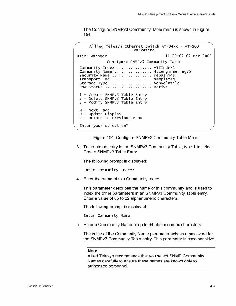
AT-S63 Management Software Menus Interface User’s Guide
The Configure SNMPv3 Community Table menu is shown in Figure 154.
Figure 154. Configure SNMPv3 Community Table Menu
3. To create an entry in the SNMPv3 Community Table, type 1 to select Create SNMPv3 Table Entry.
The following prompt is displayed:
Enter Community Index:
4. Enter the name of this Community Index.
This parameter describes the name of this community and is used to index the other parameters in an SNMPv3 Community Table entry. Enter a value of up to 32 alphanumeric characters.
The following prompt is displayed:
Enter Community Name:
5. Enter a Community Name of up to 64 alphanumeric characters.
The value of the Community Name parameter acts as a password for the SNMPv3 Community Table entry. This parameter is case sensitive.
NoteAllied Telesyn recommends that you select SNMP Community Names carefully to ensure these names are known only to authorized personnel.
Allied Telesyn Ethernet Switch AT-94xx - AT-S63Marketing
User: Manager 11:20:02 02-Mar-2005
Configure SNMPv3 Community Table
Community Index ............... ATIIndex1Community Name ................ 451engineering75Security Name ................. debashi48Transport Tag ................. sampletagStorage Type .................. NonVolatileRow Status .................... Active
1 - Create SNMPv3 Table Entry 2 - Delete SNMPv3 Table Entry3 - Modify SNMPv3 Table Entry
N - Next PageU - Update DisplayR - Return to Previous Menu
Enter your selection?
Section III: SNMPv3 457
Chapter 20: SNMPv3
The following prompt is displayed:
Enter Security Name:
6. Enter the name of an SNMPv1 and SNMPv2c user.
This name must be unique. Enter a value of up to 32 alphanumeric characters.
NoteDo not use a value configured with the User Name parameter in the SNMPv3 User Table.
The following prompt is displayed:
Enter Transport Tag:
7. Enter a name of up to 32 alphanumeric characters for the Transport Tag.
The Transport Tag parameter is similar to the Notify Tag parameter in the SNMPv3 Notify Table. Add the value you configure for the Transport Tag parameter to the Tag List parameter in the Target Address Table. In this way, the Transport Tag parameter links an SNMPv3 Community Table entry with an entry in the SNMPv3 Target Address Table. See “SNMPv3 Target Address Table” on page 377.
The following prompt is displayed:
Enter Storage type [V-volatile, N-NonVolatile]:
8. Select one of the following storage types for this table entry:
V - VolatileSelect this storage type if you do not want the ability to save an entry in the SNMPv3 Community Table to the configuration file. After making changes to an SNMPv3 Community Table entry with a Volatile storage type, the S - Save Configuration Changes option does not appear on the Main Menu.
N-NonVolatileSelect this storage type if you want the ability to save an entry in the SNMPv3 Community Table to the configuration file. After making changes to an SNMPv3 Community Table entry with a NonVolatile storage type, the S - Save Configuration Changes option appears on the Main Menu, allowing you to save your changes. Allied Telesyn recommends this storage type.
458 Section III: SNMPv3
AT-S63 Management Software Menus Interface User’s Guide
NoteThe Row Status parameter is a read-only field. The Active value indicates the SNMPv3 Community Table entry takes effect immediately.
9. After making changes, type R until you return to the Main Menu. Then type S to select Save Configuration Changes.
Deleting anSNMPv3
CommunityTable Entry
You may want to delete an entry from the SNMPv3 Community Table. When you delete an entry in the SNMPv3 Community Table, there is no way to undelete or recover the entry.
To delete an entry in the SNMPv3 Community Table, perform the following procedure:
1. Follow steps 1 through 5 in the procedure described in “Creating an SNMPv3 User Table Entry” on page 380. Or, from the Main Menu type 5->1->1->8->5.
The Configure SNMPv3 Table menu is shown in Figure 140 on page 381.
2. From the Configure SNMPv3 Table menu, type 9 to select Configure SNMPv3 Community Table.
The Configure SNMPv3 Community Table menu is shown in Figure 154 on page 457.
3. To delete an entry in the SNMPv3 Community Table, type 2 to select Delete SNMPv3 Table Entry.
The following prompt is displayed:
Enter Community Index:
4. Enter the Community Index that you want to delete.
The following prompt is displayed:
Do you want to delete this table entry?(Y/N):[Yes/No]->
5. Choose one of the following:
YType Y to delete an SNMPv3 Community table entry.
NType N to retain the SNMPv3 Community table entry.
6. After making changes, type R until you return to the Main Menu. Then type S to select Save Configuration Changes.
Section III: SNMPv3 459
Chapter 20: SNMPv3
Modifying anSNMPv3
CommunityTable Entry
For each entry in the SNMPv3 Community Table, you can modify the following parameters:
Community NameSecurity NameTransport TagStorage Type
However, you cannot modify the Community Index parameter.
Although you can display the SNMPv1 and SNMPv2c configuration created with the procedures described in “Creating an SNMP Community String” on page 81, you cannot modify these Community Table entries with the SNMPv3 Tables.
See the following procedures:
“Modifying the Community Name” on page 460“Modifying the Security Name” on page 462“Modifying the Transport Tag” on page 462“Modifying the Storage Type” on page 463
Modifying the Community Name
To modify the Community Name parameter in an SNMPv3 Community Table entry, perform the following procedure:
1. Follow steps 1 through 5 in the procedure described in “Creating an SNMPv3 User Table Entry” on page 380. Or, from the Main menu type 5->1->1->8->5.
The Configure SNMPv3 Table menu is displayed Figure 139 on page 381.
2. From the Configure SNMPv3 Table menu, type 9 to select Configure SNMPv3 Community Table.
The SNMPv3 Community Table is shown in Figure 154 on page 457.
3. From the Configure SNMPv3 Community Table, type 3 to select Modify SNMPv3 Table Entry.
460 Section III: SNMPv3

AT-S63 Management Software Menus Interface User’s Guide
The Modify SNMPv3 Community Table menu is shown in Figure 155.
Figure 155. Modify SNMPv3 Community Table Menu
4. To change the Community Name, type 1 to select Set Community Name.
The following prompt is displayed:
Enter Community Index:
5. Enter the Community Index that you want to modify.
The following prompt is displayed:
Enter Community Name:
6. Enter the new Community Name.
The value of the Community Name parameter acts as a password for the SNMPv3 Community Table entry. This parameter is case sensitive. Enter a value of up to 64 alphanumeric characters.
NoteAllied Telesyn recommends that you select SNMP Community Names carefully to ensure these names are known only to authorized personnel.
7. After making changes, type R until you return to the Main Menu. Then type S to select Save Configuration Changes.
Allied Telesyn Ethernet Switch AT-94xx - AT-S63Marketing
User: Manager 11:20:02 02-Mar-2005
Modify SNMPv3 Community Table
Community Index ............... alliedtelesynindexCommunity Name ................ 789bothel23waSecurity Name ................. busterTransport Tag ................. 72Storage Type .................. VolatileRow Status .................... Active
1 - Set Community Name2 - Set Security Name3 - Set Transport Tag4 - Set Storage Type
N - Next PageU - Update DisplayR - Return to Previous Menu
Enter your selection?
Section III: SNMPv3 461
Chapter 20: SNMPv3
Modifying the Security Name
To modify the Security Name parameter in an SNMPv3 Community Table entry, perform the following procedure:
1. Follow steps 1 through 5 in the procedure described in “Creating an SNMPv3 User Table Entry” on page 380. Or, from the Main Menu type 5->1->1->8->5.
The Configure SNMPv3 Table menu is displayed as shown in Figure 139 on page 381.
2. From the Configure SNMPv3 Table menu, type 9 to select Configure SNMPv3 Community Table.
The Configure SNMPv3 Community Table menu is shown in Figure 154 on page 457.
3. From the Configure SNMPv3 Community Table, type 3 to select Modify SNMPv3 Table Entry.
The Modify SNMPv3 Community Table menu is shown in Figure 155 on page 461.
4. To change the Security Name, type 2 to select Set Security Name.
The following prompt is displayed:
Enter Community Index:
5. Enter the Community Index of the Security Name you want to change.
The following prompt is displayed:
Enter Security Name:
6. Enter the new Security Name.
Enter a value of up to 32 alphanumeric characters.
7. After making changes, type R until you return to the Main Menu. Then type S to select Save Configuration Changes.
Modifying the Transport Tag
To modify the Transport Tag parameter in an SNMPv3 Community Table entry, perform the following procedure:
1. Follow steps 1 through 5 in the procedure described in “Creating an SNMPv3 User Table Entry” on page 380. Or, from the Main Menu type 5->1->1->8->5.
462 Section III: SNMPv3
AT-S63 Management Software Menus Interface User’s Guide
The Configure SNMPv3 Table menu is displayed as shown in Figure 139 on page 381.
2. From the Configure SNMPv3 Table menu, type 9 to select Configure SNMPv3 Community Table.
The Configure SNMPv3 Community Table menu is shown in Figure 154 on page 457.
3. From the Configure SNMPv3 Community Table, type 3 to select Modify SNMPv3 Table Entry.
The Modify SNMPv3 Community Table menu is shown in Figure 155 on page 461.
4. To change the Transport Tag, type 3 to select Set Transport Tag.
The following prompt is displayed:
Enter Community Index:
5. Enter the Community Index of the Transport Tag you want to change.
The following prompt is displayed:
Enter Transport Tag:
6. Enter the new value for the Transport Tag.
Enter a name of up to 32 alphanumeric characters.
7. After making changes, type R until you return to the Main Menu. Then type S to select Save Configuration Changes.
Modifying the Storage Type
To modify the Storage Type parameter in an SNMPv3 Community Table entry, perform the following procedure:
1. Follow steps 1 through 5 in the procedure described in “Creating an SNMPv3 User Table Entry” on page 380. Or, from the Main Menu type 5->1->1->8->5.
The Configure SNMPv3 Table menu is displayed as shown in Figure 139 on page 381.
2. From the Configure SNMPv3 Table menu, type 9 to select Configure SNMPv3 Community Table.
The Configure SNMPv3 Community Table menu is shown in Figure 154 on page 457.
Section III: SNMPv3 463
Chapter 20: SNMPv3
3. From the Configure SNMPv3 Community Table, type 3 to select Modify SNMPv3 Table Entry.
The Modify SNMPv3 Community Table Menu is shown in Figure 155 on page 461.
4. To change the Storage Type, type 4 to select Set Storage Type.
The following prompt is displayed:
Enter Community Index:
5. Enter the Community Index of the Storage Type you want to change.
The following prompt is displayed:
Enter Storage type [V-volatile, N-NonVolatile]:
6. Select one of the following storage types for this table entry:
V - VolatileSelect this storage type if you do not want the ability to an entry in the SNMPv3 Community Table to the configuration file. After making changes to an SNMP Community Table entry with a Volatile storage type, the S - Save Configuration Changes option does not appear on the Main Menu.
N-NonVolatileSelect this storage type if you want the ability to save an entry in the SNMPv3 Community Table to the configuration file. After making changes to an SNMPv3 Community Table entry with a NonVolatile storage type, the S - Save Configuration Changes option appears on the Main Menu, allowing you to save your changes. Allied Telesyn recommends this storage type.
7. After making changes, type R until you return to the Main Menu. Then type S to select Save Configuration Changes.
464 Section III: SNMPv3
AT-S63 Management Software Menus Interface User’s Guide
Displaying SNMPv3 Table Menus
The procedures in this section describe how to display the SNMPv3 Tables. The following procedures are provided:
“Displaying the Display SNMPv3 User Table Menu,” next“Displaying the Display SNMPv3 View Table Menu” on page 466“Displaying the Display SNMPv3 Access Table Menu” on page 467“Displaying the Display SNMPv3 SecurityToGroup Table Menu” on page 468“Displaying the Display SNMPv3 Notify Table Menu” on page 469“Displaying the Display SNMPv3 Target Address Table Menu” on page 470“Displaying the Display SNMPv3 Target Parameters Table Menu” on page 470“Displaying the Display SNMPv3 Community Table Menu” on page 471
Displaying theDisplay SNMPv3User Table Menu
This section describes how to display the Display SNMPv3 User Table menu. For information about the SNMPv3 User Table, see “Creating an SNMPv3 User Table Entry” on page 380.
To display the Display SNMPv3 User Table menu, perform the following procedure.
1. From the Main Menu, type 5 to select System Administration.
The System Administration menu is shown in Figure 7 on page 53.
2. From the System Administration menu, type 5 to select SNMP Configuration.
The SNMP Configuration menu is shown in Figure 16 on page 79.
3. From the SNMP Configuration menu, type 6 to select Display SNMPv3 Table.
Section III: SNMPv3 465
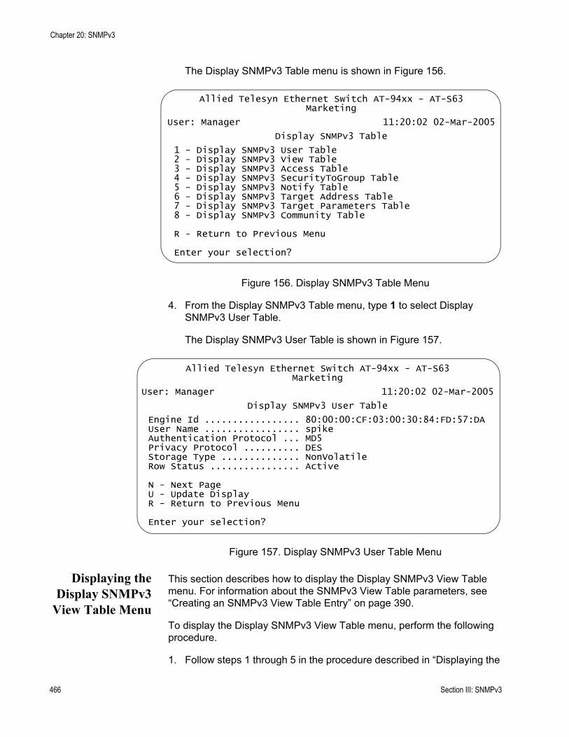
Chapter 20: SNMPv3
The Display SNMPv3 Table menu is shown in Figure 156.
Figure 156. Display SNMPv3 Table Menu
4. From the Display SNMPv3 Table menu, type 1 to select Display SNMPv3 User Table.
The Display SNMPv3 User Table is shown in Figure 157.
Figure 157. Display SNMPv3 User Table Menu
Displaying theDisplay SNMPv3
View Table Menu
This section describes how to display the Display SNMPv3 View Table menu. For information about the SNMPv3 View Table parameters, see “Creating an SNMPv3 View Table Entry” on page 390.
To display the Display SNMPv3 View Table menu, perform the following procedure.
1. Follow steps 1 through 5 in the procedure described in “Displaying the
Allied Telesyn Ethernet Switch AT-94xx - AT-S63Marketing
User: Manager 11:20:02 02-Mar-2005
Display SNMPv3 Table
1 - Display SNMPv3 User Table2 - Display SNMPv3 View Table3 - Display SNMPv3 Access Table4 - Display SNMPv3 SecurityToGroup Table5 - Display SNMPv3 Notify Table6 - Display SNMPv3 Target Address Table7 - Display SNMPv3 Target Parameters Table8 - Display SNMPv3 Community Table
R - Return to Previous Menu
Enter your selection?
Allied Telesyn Ethernet Switch AT-94xx - AT-S63Marketing
User: Manager 11:20:02 02-Mar-2005
Display SNMPv3 User Table
Engine Id ................. 80:00:00:CF:03:00:30:84:FD:57:DAUser Name ................. spikeAuthentication Protocol ... MD5Privacy Protocol .......... DESStorage Type .............. NonVolatileRow Status ................ Active
N - Next PageU - Update DisplayR - Return to Previous Menu
Enter your selection?
466 Section III: SNMPv3

AT-S63 Management Software Menus Interface User’s Guide
Display SNMPv3 User Table Menu” on page 465. Or, from the Main menu type 5->1->1->8->6.
2. From the Display SNMPv3 Table menu, type 2 to select Display SNMPv3 View Table.
The Display SNMPv3 View Table menu is shown in Figure 158.
Figure 158. Display SNMPv3 View Table Menu
Displaying theDisplay SNMPv3
Access TableMenu
This section describes how to display the Display SNMPv3 Access Table menu. For information about the SNMPv3 Access Table parameters, see “Creating an SNMPv3 Access Table Entry” on page 399.
To display the Display SNMPv3 Access Table menu, perform the following procedure.
1. Follow steps 1 through 5 in the procedure described in “Displaying the Display SNMPv3 User Table Menu” on page 465. Or, from the Main Menu type 5->1->1->8->6.
2. From the Display SNMPv3 Table menu, type 3 to select Display SNMPv3 Access Table.
Allied Telesyn Ethernet Switch AT-94xx - AT-S63Marketing
User: Manager 11:20:02 02-Mar-2005
Display SNMPv3 View Table
View Name ................... tcpSubtree OID ................. 1.3.6.1Subtree Mask ................ View Type ................... IncludedStorage Type ................ NonVolatileRow Status .................. Active
N - Next PageU - Update DisplayR - Return to Previous Menu
Enter your selection?
Section III: SNMPv3 467
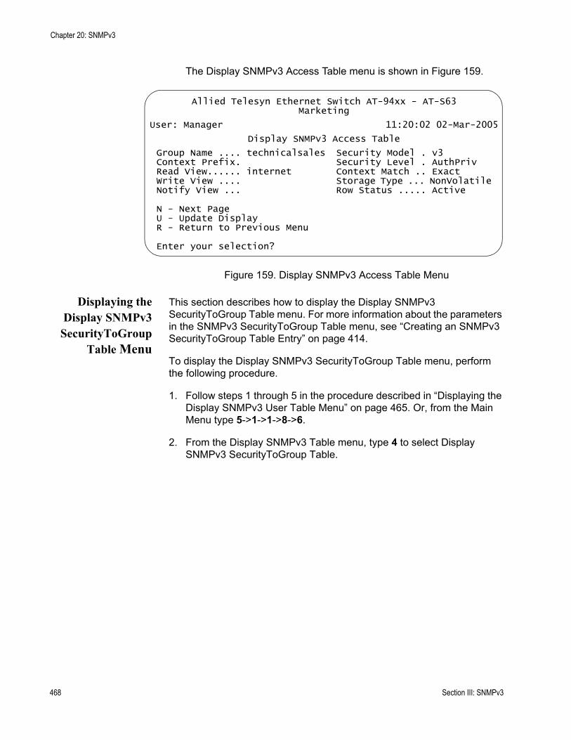
Chapter 20: SNMPv3
The Display SNMPv3 Access Table menu is shown in Figure 159.
Figure 159. Display SNMPv3 Access Table Menu
Displaying theDisplay SNMPv3SecurityToGroup
Table Menu
This section describes how to display the Display SNMPv3 SecurityToGroup Table menu. For more information about the parameters in the SNMPv3 SecurityToGroup Table menu, see “Creating an SNMPv3 SecurityToGroup Table Entry” on page 414.
To display the Display SNMPv3 SecurityToGroup Table menu, perform the following procedure.
1. Follow steps 1 through 5 in the procedure described in “Displaying the Display SNMPv3 User Table Menu” on page 465. Or, from the Main Menu type 5->1->1->8->6.
2. From the Display SNMPv3 Table menu, type 4 to select Display SNMPv3 SecurityToGroup Table.
Allied Telesyn Ethernet Switch AT-94xx - AT-S63Marketing
User: Manager 11:20:02 02-Mar-2005
Display SNMPv3 Access Table
Group Name .... technicalsales Security Model . v3Context Prefix. Security Level . AuthPrivRead View...... internet Context Match .. ExactWrite View .... Storage Type ... NonVolatileNotify View ... Row Status ..... Active
N - Next PageU - Update DisplayR - Return to Previous Menu
Enter your selection?
468 Section III: SNMPv3
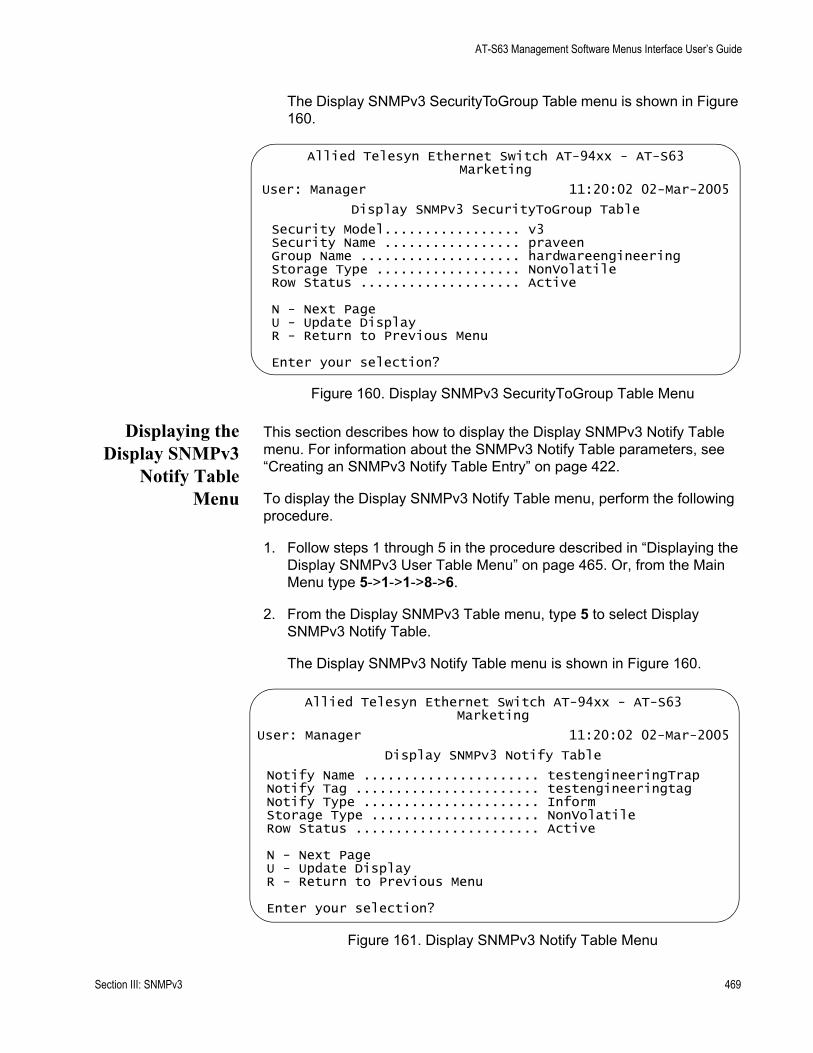
AT-S63 Management Software Menus Interface User’s Guide
The Display SNMPv3 SecurityToGroup Table menu is shown in Figure 160.
Figure 160. Display SNMPv3 SecurityToGroup Table Menu
Displaying theDisplay SNMPv3
Notify TableMenu
This section describes how to display the Display SNMPv3 Notify Table menu. For information about the SNMPv3 Notify Table parameters, see “Creating an SNMPv3 Notify Table Entry” on page 422.
To display the Display SNMPv3 Notify Table menu, perform the following procedure.
1. Follow steps 1 through 5 in the procedure described in “Displaying the Display SNMPv3 User Table Menu” on page 465. Or, from the Main Menu type 5->1->1->8->6.
2. From the Display SNMPv3 Table menu, type 5 to select Display SNMPv3 Notify Table.
The Display SNMPv3 Notify Table menu is shown in Figure 160.
Figure 161. Display SNMPv3 Notify Table Menu
Allied Telesyn Ethernet Switch AT-94xx - AT-S63Marketing
User: Manager 11:20:02 02-Mar-2005
Display SNMPv3 SecurityToGroup Table
Security Model................. v3Security Name ................. praveenGroup Name .................... hardwareengineeringStorage Type .................. NonVolatileRow Status .................... Active
N - Next PageU - Update DisplayR - Return to Previous Menu
Enter your selection?
Allied Telesyn Ethernet Switch AT-94xx - AT-S63Marketing
User: Manager 11:20:02 02-Mar-2005
Display SNMPv3 Notify Table
Notify Name ...................... testengineeringTrapNotify Tag ....................... testengineeringtagNotify Type ...................... InformStorage Type ..................... NonVolatileRow Status ....................... Active
N - Next PageU - Update DisplayR - Return to Previous Menu
Enter your selection?
Section III: SNMPv3 469
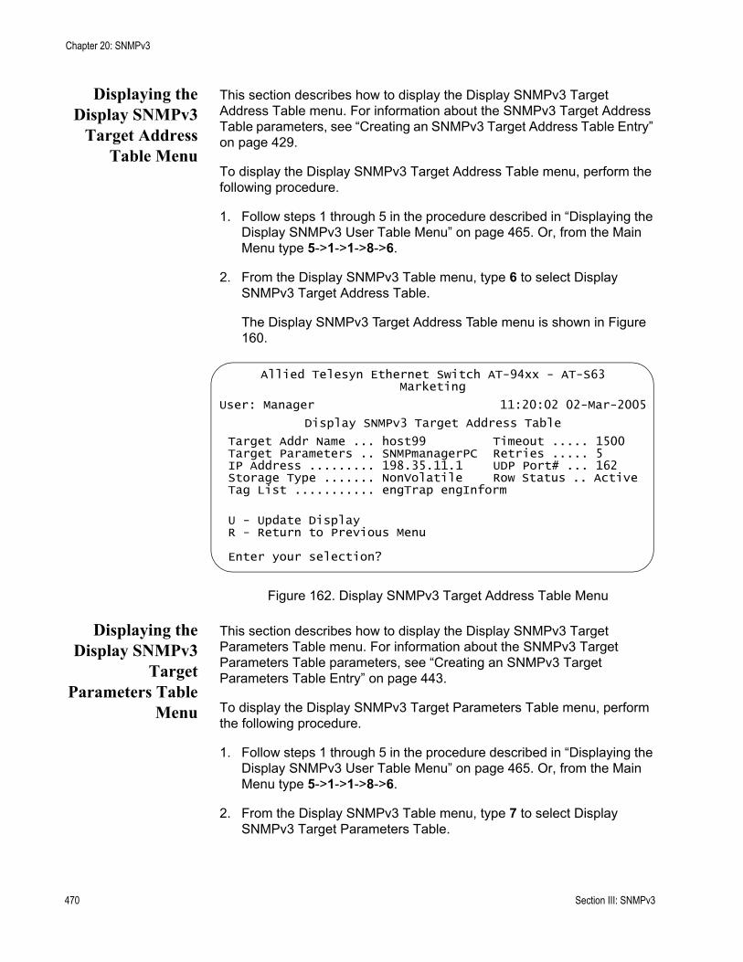
Chapter 20: SNMPv3
Displaying theDisplay SNMPv3
Target AddressTable Menu
This section describes how to display the Display SNMPv3 Target Address Table menu. For information about the SNMPv3 Target Address Table parameters, see “Creating an SNMPv3 Target Address Table Entry” on page 429.
To display the Display SNMPv3 Target Address Table menu, perform the following procedure.
1. Follow steps 1 through 5 in the procedure described in “Displaying the Display SNMPv3 User Table Menu” on page 465. Or, from the Main Menu type 5->1->1->8->6.
2. From the Display SNMPv3 Table menu, type 6 to select Display SNMPv3 Target Address Table.
The Display SNMPv3 Target Address Table menu is shown in Figure 160.
Figure 162. Display SNMPv3 Target Address Table Menu
Displaying theDisplay SNMPv3
TargetParameters Table
Menu
This section describes how to display the Display SNMPv3 Target Parameters Table menu. For information about the SNMPv3 Target Parameters Table parameters, see “Creating an SNMPv3 Target Parameters Table Entry” on page 443.
To display the Display SNMPv3 Target Parameters Table menu, perform the following procedure.
1. Follow steps 1 through 5 in the procedure described in “Displaying the Display SNMPv3 User Table Menu” on page 465. Or, from the Main Menu type 5->1->1->8->6.
2. From the Display SNMPv3 Table menu, type 7 to select Display SNMPv3 Target Parameters Table.
Allied Telesyn Ethernet Switch AT-94xx - AT-S63Marketing
User: Manager 11:20:02 02-Mar-2005
Display SNMPv3 Target Address Table
Target Addr Name ... host99 Timeout ..... 1500Target Parameters .. SNMPmanagerPC Retries ..... 5IP Address ......... 198.35.11.1 UDP Port# ... 162Storage Type ....... NonVolatile Row Status .. ActiveTag List ........... engTrap engInform
U - Update DisplayR - Return to Previous Menu
Enter your selection?
470 Section III: SNMPv3
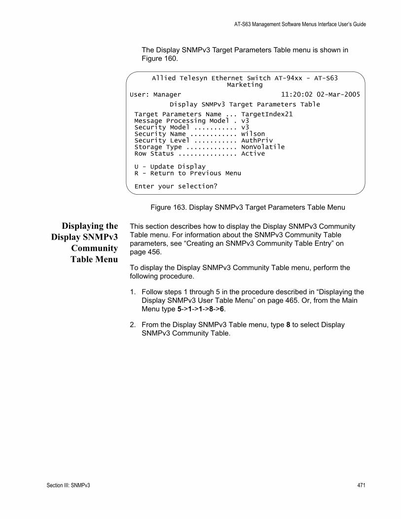
AT-S63 Management Software Menus Interface User’s Guide
The Display SNMPv3 Target Parameters Table menu is shown in Figure 160.
Figure 163. Display SNMPv3 Target Parameters Table Menu
Displaying theDisplay SNMPv3
CommunityTable Menu
This section describes how to display the Display SNMPv3 Community Table menu. For information about the SNMPv3 Community Table parameters, see “Creating an SNMPv3 Community Table Entry” on page 456.
To display the Display SNMPv3 Community Table menu, perform the following procedure.
1. Follow steps 1 through 5 in the procedure described in “Displaying the Display SNMPv3 User Table Menu” on page 465. Or, from the Main Menu type 5->1->1->8->6.
2. From the Display SNMPv3 Table menu, type 8 to select Display SNMPv3 Community Table.
Allied Telesyn Ethernet Switch AT-94xx - AT-S63Marketing
User: Manager 11:20:02 02-Mar-2005
Display SNMPv3 Target Parameters Table
Target Parameters Name ... TargetIndex21Message Processing Model . v3Security Model ........... v3Security Name ............ wilsonSecurity Level ........... AuthPrivStorage Type ............. NonVolatileRow Status ............... Active
U - Update DisplayR - Return to Previous Menu
Enter your selection?
Section III: SNMPv3 471
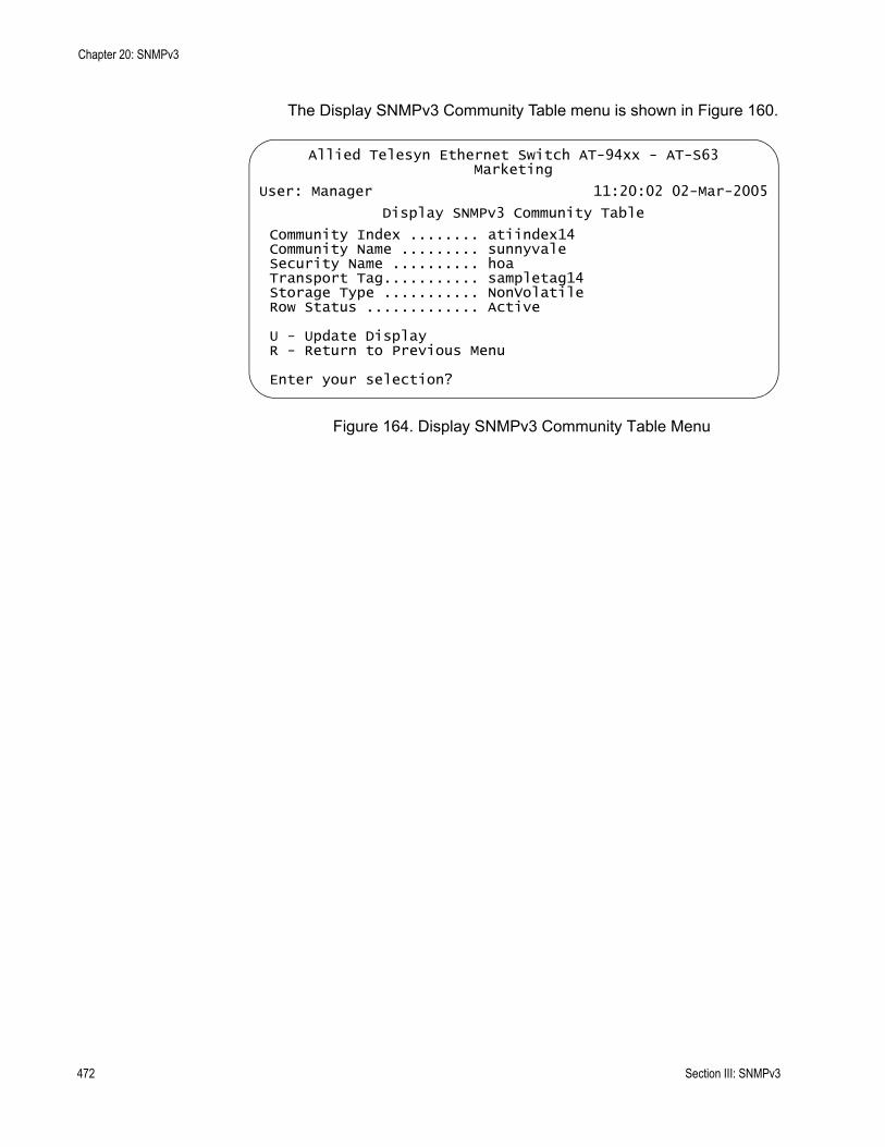
Chapter 20: SNMPv3
The Display SNMPv3 Community Table menu is shown in Figure 160.
Figure 164. Display SNMPv3 Community Table Menu
Allied Telesyn Ethernet Switch AT-94xx - AT-S63Marketing
User: Manager 11:20:02 02-Mar-2005
Display SNMPv3 Community Table
Community Index ........ atiindex14Community Name ......... sunnyvaleSecurity Name .......... hoaTransport Tag........... sampletag14Storage Type ........... NonVolatileRow Status ............. Active
U - Update DisplayR - Return to Previous Menu
Enter your selection?
472 Section III: SNMPv3
Section IV
Spanning Tree Protocols
The chapters in this section provide information and procedures for the spanning tree protocols. The chapters include:
Chapter 21, “STP and RSTP” on page 475Chapter 22, “MSTP” on page 501
Section IV: Spanning Tree Protocols 473

474 Section IV: Spanning Tree Protocols
Chapter 21
STP and RSTP
This chapter provides background information on the Spanning Tree Protocol (STP) and Rapid Spanning Tree Protocol (RSTP). The chapter also contains procedures on how to adjust the STP and RSTP bridge and port parameters. The sections in this chapter include:
“STP and RSTP Overview” on page 476“Enabling or Disabling a Spanning Tree Protocol” on page 485“Configuring STP” on page 487“Configuring RSTP” on page 493
The Multiple Spanning Tree Protocol is described in Chapter 22, “MSTP” on page 501.
NoteFor detailed information on the Spanning Tree Protocol, refer to IEEE Std 802.1D. For detailed information on the Rapid Spanning Tree Protocol, refer to IEEE Std 802.1w.
Section IV: Spanning Tree Protocols 475

Chapter 21: STP and RSTP
STP and RSTP Overview
The performance of a Ethernet network can be negatively impacted by the formation of a data loop in the network topology. A data loop exists when two or more nodes on a network can transmit data to each other over more than one data path. The problem that data loops pose is that data packets can become caught in repeating cycles, referred to as broadcast storms, that needlessly consume network bandwidth and can significantly reduce network performance.
STP and RSTP prevent data loops from forming by ensuring that only one path exists between the end nodes in your network. Where multiple paths exist, these protocols place the extra paths in a standby or blocking mode, leaving only one main active path.
STP and RSTP can also activate a redundant path if the main path goes down. So not only do these protocols guard against multiple links between segments and the risk of broadcast storms, but they can also maintain network connectivity by activating a backup redundant path in case a main link fails.
Where the two protocols differ is in the time each takes to complete the process referred to as convergence. When a change is made to the network topology, such as the addition of a new bridge, a spanning tree protocol must determine whether there are redundant paths that must be blocked to prevent data loops, or activated to maintain communications between the various network segments. This is the process of convergence.
With STP, convergence can take up to a minute to complete in a large network. This can result in the loss of communication between various parts of the network during the convergence process, and the subsequent lost of data packets.
RSTP is much faster. It can complete a convergence in seconds, and so greatly diminish the possible impact the process can have on your network.
Only one spanning tree can be active on the switch at a time. The default is RSTP.
The STP implementation on the AT-S63 management software complies with the IEEE 802.1d standard. The RSTP implementation complies with the IEEE 802.1w standard. The following subsections provide a basic overview on how STP and RSTP operate and define the different parameters that you can adjust.
476 Section IV: Spanning Tree Protocols
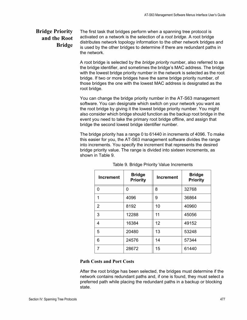
AT-S63 Management Software Menus Interface User’s Guide
Bridge Priorityand the Root
Bridge
The first task that bridges perform when a spanning tree protocol is activated on a network is the selection of a root bridge. A root bridge distributes network topology information to the other network bridges and is used by the other bridges to determine if there are redundant paths in the network.
A root bridge is selected by the bridge priority number, also referred to as the bridge identifier, and sometimes the bridge’s MAC address. The bridge with the lowest bridge priority number in the network is selected as the root bridge. If two or more bridges have the same bridge priority number, of those bridges the one with the lowest MAC address is designated as the root bridge.
You can change the bridge priority number in the AT-S63 management software. You can designate which switch on your network you want as the root bridge by giving it the lowest bridge priority number. You might also consider which bridge should function as the backup root bridge in the event you need to take the primary root bridge offline, and assign that bridge the second lowest bridge identifier number.
The bridge priority has a range 0 to 61440 in increments of 4096. To make this easier for you, the AT-S63 management software divides the range into increments. You specify the increment that represents the desired bridge priority value. The range is divided into sixteen increments, as shown in Table 9.
Path Costs and Port Costs
After the root bridge has been selected, the bridges must determine if the network contains redundant paths and, if one is found, they must select a preferred path while placing the redundant paths in a backup or blocking state.
Table 9. Bridge Priority Value Increments
Increment Bridge Priority Increment Bridge
Priority
0 0 8 32768
1 4096 9 36864
2 8192 10 40960
3 12288 11 45056
4 16384 12 49152
5 20480 13 53248
6 24576 14 57344
7 28672 15 61440
Section IV: Spanning Tree Protocols 477
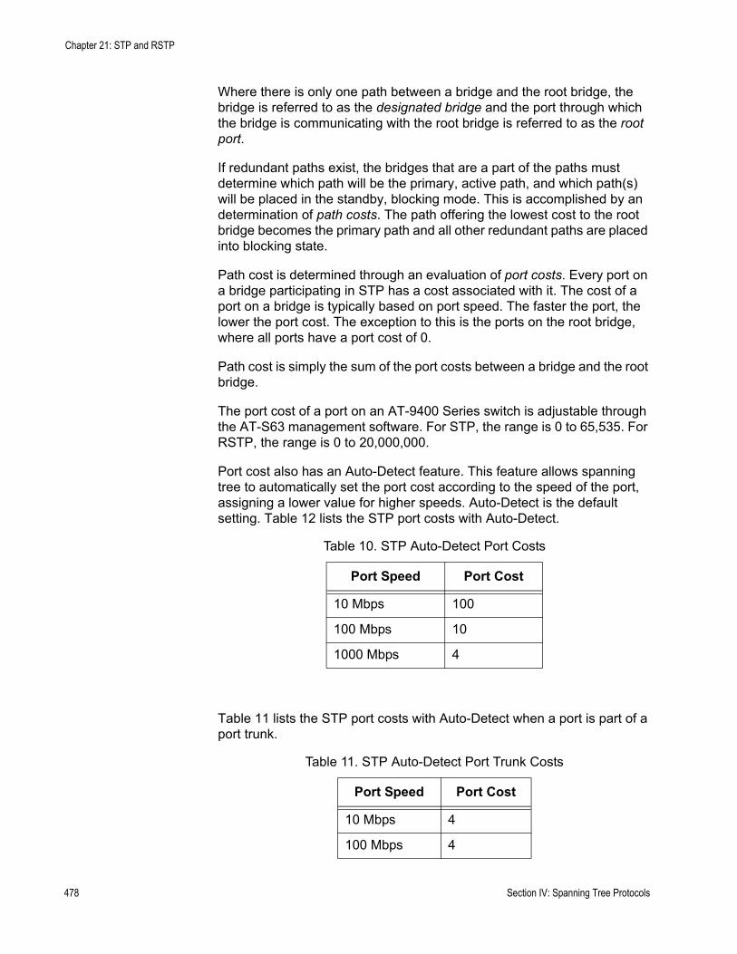
Chapter 21: STP and RSTP
Where there is only one path between a bridge and the root bridge, the bridge is referred to as the designated bridge and the port through which the bridge is communicating with the root bridge is referred to as the root port.
If redundant paths exist, the bridges that are a part of the paths must determine which path will be the primary, active path, and which path(s) will be placed in the standby, blocking mode. This is accomplished by an determination of path costs. The path offering the lowest cost to the root bridge becomes the primary path and all other redundant paths are placed into blocking state.
Path cost is determined through an evaluation of port costs. Every port on a bridge participating in STP has a cost associated with it. The cost of a port on a bridge is typically based on port speed. The faster the port, the lower the port cost. The exception to this is the ports on the root bridge, where all ports have a port cost of 0.
Path cost is simply the sum of the port costs between a bridge and the root bridge.
The port cost of a port on an AT-9400 Series switch is adjustable through the AT-S63 management software. For STP, the range is 0 to 65,535. For RSTP, the range is 0 to 20,000,000.
Port cost also has an Auto-Detect feature. This feature allows spanning tree to automatically set the port cost according to the speed of the port, assigning a lower value for higher speeds. Auto-Detect is the default setting. Table 12 lists the STP port costs with Auto-Detect.
Table 11 lists the STP port costs with Auto-Detect when a port is part of a port trunk.
Table 10. STP Auto-Detect Port Costs
Port Speed Port Cost
10 Mbps 100
100 Mbps 10
1000 Mbps 4
Table 11. STP Auto-Detect Port Trunk Costs
Port Speed Port Cost
10 Mbps 4
100 Mbps 4
478 Section IV: Spanning Tree Protocols

AT-S63 Management Software Menus Interface User’s Guide
Table 12 lists the RSTP port costs with Auto-Detect.
Table 13 lists the RSTP port costs with Auto-Detect when the port is part of a port trunk.
You can override Auto-Detect and set the port cost manually.
Port Priority
If two paths have the same port cost, the bridges must select a preferred path. In some instances this can involve the use of the port priority parameter. This parameter is used as a tie breaker when two paths have the same cost.
The range for port priority is 0 to 240. As with bridge priority, this range is broken into increments, in this case multiples of 16. To select a port priority for a port, you enter the increment of the desired value. Table 14 lists the values and increments. The default value is 128, which is increment 8.
1000 Mbps 2
Table 12. RSTP Auto-Detect Port Costs
Port Speed Port Cost
10 Mbps 2,000,000
100 Mbps 200,000
1000 Mbps 20,000
Table 13. RSTP Auto-Detect Port Trunk Costs
Port Speed Port Cost
10 Mbps 20,000
100 Mbps 20,000
1000 Mbps 2,000
Table 14. Port Priority Value Increments
Increment Bridge Priority Increment Bridge
Priority
0 0 8 128
1 16 9 144
Table 11. STP Auto-Detect Port Trunk Costs
Port Speed Port Cost
Section IV: Spanning Tree Protocols 479
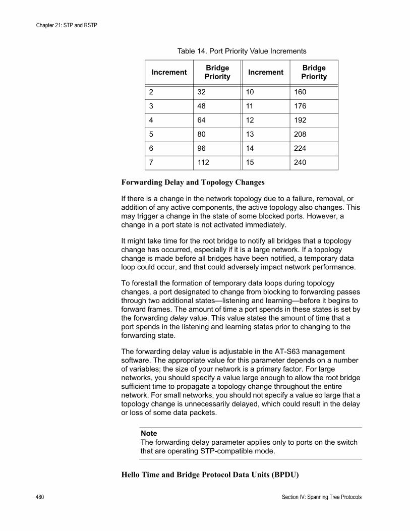
Chapter 21: STP and RSTP
Forwarding Delay and Topology Changes
If there is a change in the network topology due to a failure, removal, or addition of any active components, the active topology also changes. This may trigger a change in the state of some blocked ports. However, a change in a port state is not activated immediately.
It might take time for the root bridge to notify all bridges that a topology change has occurred, especially if it is a large network. If a topology change is made before all bridges have been notified, a temporary data loop could occur, and that could adversely impact network performance.
To forestall the formation of temporary data loops during topology changes, a port designated to change from blocking to forwarding passes through two additional states—listening and learning—before it begins to forward frames. The amount of time a port spends in these states is set by the forwarding delay value. This value states the amount of time that a port spends in the listening and learning states prior to changing to the forwarding state.
The forwarding delay value is adjustable in the AT-S63 management software. The appropriate value for this parameter depends on a number of variables; the size of your network is a primary factor. For large networks, you should specify a value large enough to allow the root bridge sufficient time to propagate a topology change throughout the entire network. For small networks, you should not specify a value so large that a topology change is unnecessarily delayed, which could result in the delay or loss of some data packets.
NoteThe forwarding delay parameter applies only to ports on the switch that are operating STP-compatible mode.
Hello Time and Bridge Protocol Data Units (BPDU)
2 32 10 160
3 48 11 176
4 64 12 192
5 80 13 208
6 96 14 224
7 112 15 240
Table 14. Port Priority Value Increments
Increment Bridge Priority Increment Bridge
Priority
480 Section IV: Spanning Tree Protocols
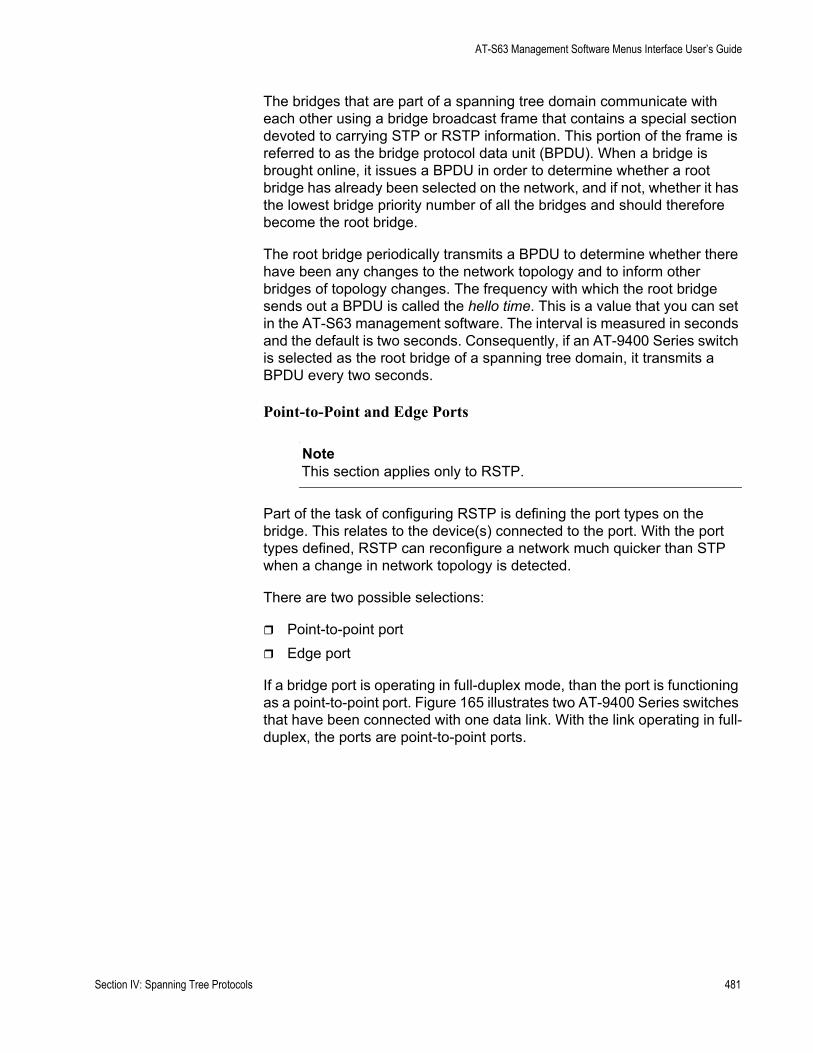
AT-S63 Management Software Menus Interface User’s Guide
The bridges that are part of a spanning tree domain communicate with each other using a bridge broadcast frame that contains a special section devoted to carrying STP or RSTP information. This portion of the frame is referred to as the bridge protocol data unit (BPDU). When a bridge is brought online, it issues a BPDU in order to determine whether a root bridge has already been selected on the network, and if not, whether it has the lowest bridge priority number of all the bridges and should therefore become the root bridge.
The root bridge periodically transmits a BPDU to determine whether there have been any changes to the network topology and to inform other bridges of topology changes. The frequency with which the root bridge sends out a BPDU is called the hello time. This is a value that you can set in the AT-S63 management software. The interval is measured in seconds and the default is two seconds. Consequently, if an AT-9400 Series switch is selected as the root bridge of a spanning tree domain, it transmits a BPDU every two seconds.
Point-to-Point and Edge Ports
NoteThis section applies only to RSTP.
Part of the task of configuring RSTP is defining the port types on the bridge. This relates to the device(s) connected to the port. With the port types defined, RSTP can reconfigure a network much quicker than STP when a change in network topology is detected.
There are two possible selections:
Point-to-point portEdge port
If a bridge port is operating in full-duplex mode, than the port is functioning as a point-to-point port. Figure 165 illustrates two AT-9400 Series switches that have been connected with one data link. With the link operating in full-duplex, the ports are point-to-point ports.
Section IV: Spanning Tree Protocols 481
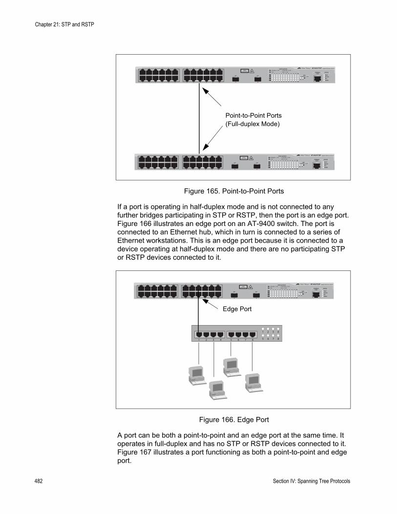
Chapter 21: STP and RSTP
Figure 165. Point-to-Point Ports
If a port is operating in half-duplex mode and is not connected to any further bridges participating in STP or RSTP, then the port is an edge port. Figure 166 illustrates an edge port on an AT-9400 switch. The port is connected to an Ethernet hub, which in turn is connected to a series of Ethernet workstations. This is an edge port because it is connected to a device operating at half-duplex mode and there are no participating STP or RSTP devices connected to it.
Figure 166. Edge Port
A port can be both a point-to-point and an edge port at the same time. It operates in full-duplex and has no STP or RSTP devices connected to it. Figure 167 illustrates a port functioning as both a point-to-point and edge port.
Point-to-Point Ports(Full-duplex Mode)
FAULT
RPS
MASTER
POWER
CLASS 1LASER PRODUCT
STATUSTERMINALPORT
1 3 5 7 9 11
2 4 6 8 10 12
13 15 17 19 21 23R
14 16 18 20 22 24R
AT-9424T/SP Gigabit Ethernet Switch
1 3 5 7 9 11 13 15 17 19 21 23R
2 4 6 8 10 12 14 16 18 20 22 24R
23 24
L/A
D/C
D/C
L/A
D/C
L/A 1000 LINK / ACT
HDX / COLFDX
10/100 LINK / ACTPORT ACTIVITY
L/A
1000 LINK / ACTSFPSFP
24
SFP
23
Edge Port
FAULT
RPS
MASTER
POWER
CLASS 1LASER PRODUCT
STATUSTERMINALPORT
1 3 5 7 9 11
2 4 6 8 10 12
13 15 17 19 21 23R
14 16 18 20 22 24R
AT-9424T/SP Gigabit Ethernet Switch
1 3 5 7 9 11 13 15 17 19 21 23R
2 4 6 8 10 12 14 16 18 20 22 24R
23 24
L/A
D/C
D/C
L/A
D/C
L/A 1000 LINK / ACT
HDX / COLFDX
10/100 LINK / ACTPORT ACTIVITY
L/A
1000 LINK / ACTSFPSFP
24
SFP
23
87654321 8765
4321
482 Section IV: Spanning Tree Protocols
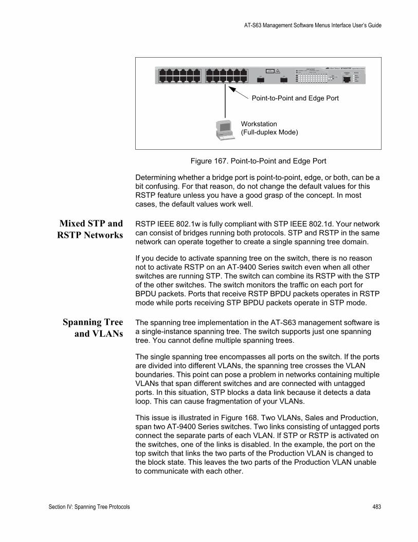
AT-S63 Management Software Menus Interface User’s Guide
Figure 167. Point-to-Point and Edge Port
Determining whether a bridge port is point-to-point, edge, or both, can be a bit confusing. For that reason, do not change the default values for this RSTP feature unless you have a good grasp of the concept. In most cases, the default values work well.
Mixed STP andRSTP Networks
RSTP IEEE 802.1w is fully compliant with STP IEEE 802.1d. Your network can consist of bridges running both protocols. STP and RSTP in the same network can operate together to create a single spanning tree domain.
If you decide to activate spanning tree on the switch, there is no reason not to activate RSTP on an AT-9400 Series switch even when all other switches are running STP. The switch can combine its RSTP with the STP of the other switches. The switch monitors the traffic on each port for BPDU packets. Ports that receive RSTP BPDU packets operates in RSTP mode while ports receiving STP BPDU packets operate in STP mode.
Spanning Treeand VLANs
The spanning tree implementation in the AT-S63 management software is a single-instance spanning tree. The switch supports just one spanning tree. You cannot define multiple spanning trees.
The single spanning tree encompasses all ports on the switch. If the ports are divided into different VLANs, the spanning tree crosses the VLAN boundaries. This point can pose a problem in networks containing multiple VLANs that span different switches and are connected with untagged ports. In this situation, STP blocks a data link because it detects a data loop. This can cause fragmentation of your VLANs.
This issue is illustrated in Figure 168. Two VLANs, Sales and Production, span two AT-9400 Series switches. Two links consisting of untagged ports connect the separate parts of each VLAN. If STP or RSTP is activated on the switches, one of the links is disabled. In the example, the port on the top switch that links the two parts of the Production VLAN is changed to the block state. This leaves the two parts of the Production VLAN unable to communicate with each other.
Point-to-Point and Edge Port
FAULT
RPS
MASTER
POWER
CLASS 1LASER PRODUCT
STATUSTERMINALPORT
1 3 5 7 9 11
2 4 6 8 10 12
13 15 17 19 21 23R
14 16 18 20 22 24R
AT-9424T/SP Gigabit Ethernet Switch
1 3 5 7 9 11 13 15 17 19 21 23R
2 4 6 8 10 12 14 16 18 20 22 24R
23 24
L/A
D/C
D/C
L/A
D/C
L/A 1000 LINK / ACT
HDX / COLFDX
10/100 LINK / ACTPORT ACTIVITY
L/A
1000 LINK / ACTSFPSFP
24
SFP
23
Workstation(Full-duplex Mode)
Section IV: Spanning Tree Protocols 483
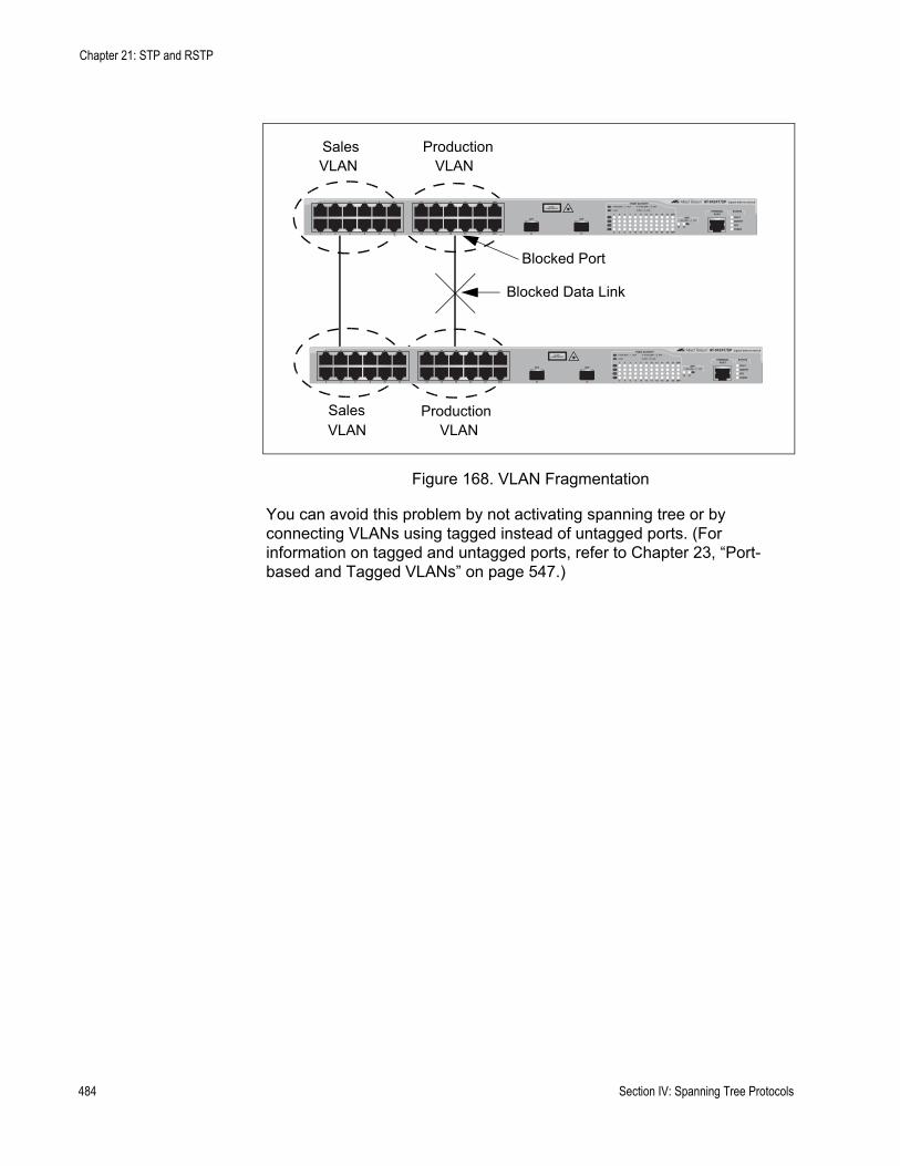
Chapter 21: STP and RSTP
Figure 168. VLAN Fragmentation
You can avoid this problem by not activating spanning tree or by connecting VLANs using tagged instead of untagged ports. (For information on tagged and untagged ports, refer to Chapter 23, “Port-based and Tagged VLANs” on page 547.)
Sales VLAN
ProductionVLAN
ProductionVLAN
Sales VLAN
Blocked Port
Blocked Data Link
FAULT
RPS
MASTER
POWER
CLASS 1LASER PRODUCT
STATUSTERMINALPORT
1 3 5 7 9 11
2 4 6 8 10 12
13 15 17 19 21 23R
14 16 18 20 22 24R
AT-9424T/SP Gigabit Ethernet Switch
1 3 5 7 9 11 13 15 17 19 21 23R
2 4 6 8 10 12 14 16 18 20 22 24R
23 24
L/A
D/C
D/C
L/A
D/C
L/A 1000 LINK / ACT
HDX / COLFDX
10/100 LINK / ACTPORT ACTIVITY
L/A
1000 LINK / ACTSFPSFP
24
SFP
23
484 Section IV: Spanning Tree Protocols

AT-S63 Management Software Menus Interface User’s Guide
Enabling or Disabling a Spanning Tree Protocol
The AT-S63 management software supports STP, RSTP, and MSTP. However, only one spanning tree protocol can be active on the switch at a time. Before you can enable a spanning tree protocol, you must first select it as the active spanning tree protocol on the switch. After you have selected it as the active protocol, you can then configure it and enable or disable it.
To select and activate a spanning tree protocol, or to disable spanning tree, perform the following procedure:
1. From the Main Menu, type 3 to select Spanning Tree Configuration.
The Spanning Tree Configuration menu is shown in Figure 169.
Figure 169. Spanning Tree Configuration Menu
NoteDo not enable spanning tree on the switch until after you have selected an activate spanning tree protocol and configured the settings. If you only want to disable spanning tree, go to step 5.
2. To change the active version of spanning tree on the switch, type 2 to select Active Protocol Version.
The following prompt is displayed:
Enter new value (S-STP, R-RSTP, M-MSTP):
3. Type S to select STP or R to select RSTP, or M to select MSTP.
NoteA change to the active spanning tree is automatically saved on the switch.
Allied Telesyn Ethernet Switch AT-94xx - AT-S63Marketing
User: Manager 11:20:02 02-Mar-2005
Spanning Tree Configuration
1 - Spanning Tree Status ...... Disabled2 - Active Protocol Version ... RSTP3 - Configure Active Protocol
R - Return to Previous Menu
Enter your selection?
Section IV: Spanning Tree Protocols 485
Chapter 21: STP and RSTP
4. If you selected STP as the active spanning tree protocol, go to “Configuring STP” on page 487 for further instructions. If you selected RSTP, go to “Configuring RSTP” on page 493. Multiple Spanning Tree Protocol (MSTP) is described in Chapter 22, “MSTP” on page 501.
NoteAfter you have configured the spanning tree parameters, perform steps 5 through 7 to enable spanning tree.
5. To enable or disable spanning tree, type 1 to select Spanning Tree Status.
The following prompt is displayed:
Enter new value (E-Enable, D-Disable):
6. Type E to enable spanning tree or D to disable it. The default is disabled.
7. After making changes, type R until you return to the Main Menu. Then type S to select Save Configuration Changes.
486 Section IV: Spanning Tree Protocols
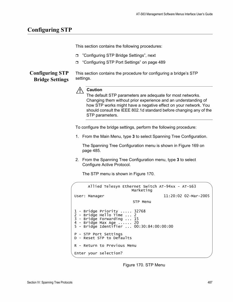
AT-S63 Management Software Menus Interface User’s Guide
Configuring STP
This section contains the following procedures:
”Configuring STP Bridge Settings”, next“Configuring STP Port Settings” on page 489
Configuring STPBridge Settings
This section contains the procedure for configuring a bridge’s STP settings.
CautionThe default STP parameters are adequate for most networks. Changing them without prior experience and an understanding of how STP works might have a negative effect on your network. You should consult the IEEE 802.1d standard before changing any of the STP parameters.
To configure the bridge settings, perform the following procedure:
1. From the Main Menu, type 3 to select Spanning Tree Configuration.
The Spanning Tree Configuration menu is shown in Figure 169 on page 485.
2. From the Spanning Tree Configuration menu, type 3 to select Configure Active Protocol.
The STP menu is shown in Figure 170.
Figure 170. STP Menu
Allied Telesyn Ethernet Switch AT-94xx - AT-S63Marketing
User: Manager 11:20:02 02-Mar-2005
STP Menu
1 - Bridge Priority ..... 327682 - Bridge Hello Time ... 23 - Bridge Forwarding ... 154 - Bridge Max Age ...... 205 - Bridge Identifier ... 00:30:84:00:00:00
P - STP Port SettingsD - Reset STP to Defaults
R - Return to Previous Menu
Enter your selection?
Section IV: Spanning Tree Protocols 487
Chapter 21: STP and RSTP
3. Adjust the following parameters as needed.
1 - Bridge PriorityThe priority number for the bridge. This number is used to determine the root bridge for RSTP. The bridge with the lowest priority number is selected as the root bridge. If two or more bridges have the same priority value, the bridge with the numerically lowest MAC address becomes the root bridge. When a root bridge goes offline, the bridge with the next priority number automatically takes over as the root bridge. This parameter can be from 0 (zero) to 61,440 in increments of 4096, with 0 being the highest priority. For a list of the increments, refer to Table 9, Bridge Priority Value Increments on page 477.
2 - Bridge Hello TimeThe time interval between generating and sending configuration messages by the bridge. This parameter can be from 1 to 10 seconds. The default is 2 seconds.
3 - Bridge ForwardingThe waiting period in seconds before a bridge changes to a new state, for example, becomes the new root bridge after the topology changes. If the bridge transitions too soon, not all links may have yet adapted to the change, resulting in network loops. The range is 4 to 30 seconds. The default is 15 seconds.
4 - Bridge Max AgeThe length of time after which stored bridge protocol data units (BPDUs) are deleted by the bridge. All bridges in a bridged LAN use this aging time to test the age of stored configuration messages called bridge protocol data units (BPDUs). For example, if you use the default value 20, all bridges delete current configuration messages after 20 seconds. This parameter can be from 6 to 40 seconds.
When you select a value for maximum age, observe the following rules:
MaxAge must be greater than (2 x (HelloTime + 1)).
MaxAge must be less than (2 x (ForwardingDelay - 1)).
NoteThe aging time for BPDUs is different from the aging time used by the MAC address table.
5 - Bridge IdentifierThe MAC address of the switch. This value cannot be changed.
4. After making changes, type R until you return to the Main Menu. Then type S to select Save Configuration Changes.
5. To change STP port settings, go to the next procedure.
488 Section IV: Spanning Tree Protocols

AT-S63 Management Software Menus Interface User’s Guide
Configuring STPPort Settings
To adjust STP port parameters, perform the following procedure:
1. From the Main Menu, type 3 to select Spanning Tree Configuration.
The Spanning Tree Configuration menu is shown in Figure 169 on page 485.
2. From the Spanning Tree Configuration menu, type 3 to select Configure Active Protocol.
The STP menu is shown in Figure 170 on page 487.
3. From the STP menu, type P to select STP Port Parameters.
The STP Port Parameters menu is shown in Figure 171.
Figure 171. STP Port Parameters Menu
4. Type 1 to select Configure STP Port Settings.
The following prompt is displayed:
Start Port to Configure [1 to 26] ->
5. Enter the number of the port you want to configure. To configure a range of ports, enter the first port of the range.
The following prompt is displayed:
End Port to Configure [1 to 24] ->
6. To configure just one port, enter the same port number here as you entered in the previous step. To configure a range of ports, enter the last port of the range.
Allied Telesyn Ethernet Switch AT-94xx - AT-S63Marketing
User: Manager 11:20:02 02-Mar-2005
STP Port Parameters
1 - Configure STP Port Settings2 - Display STP Port Configuration
R - Return to Previous Menu
Enter your selection?
Section IV: Spanning Tree Protocols 489
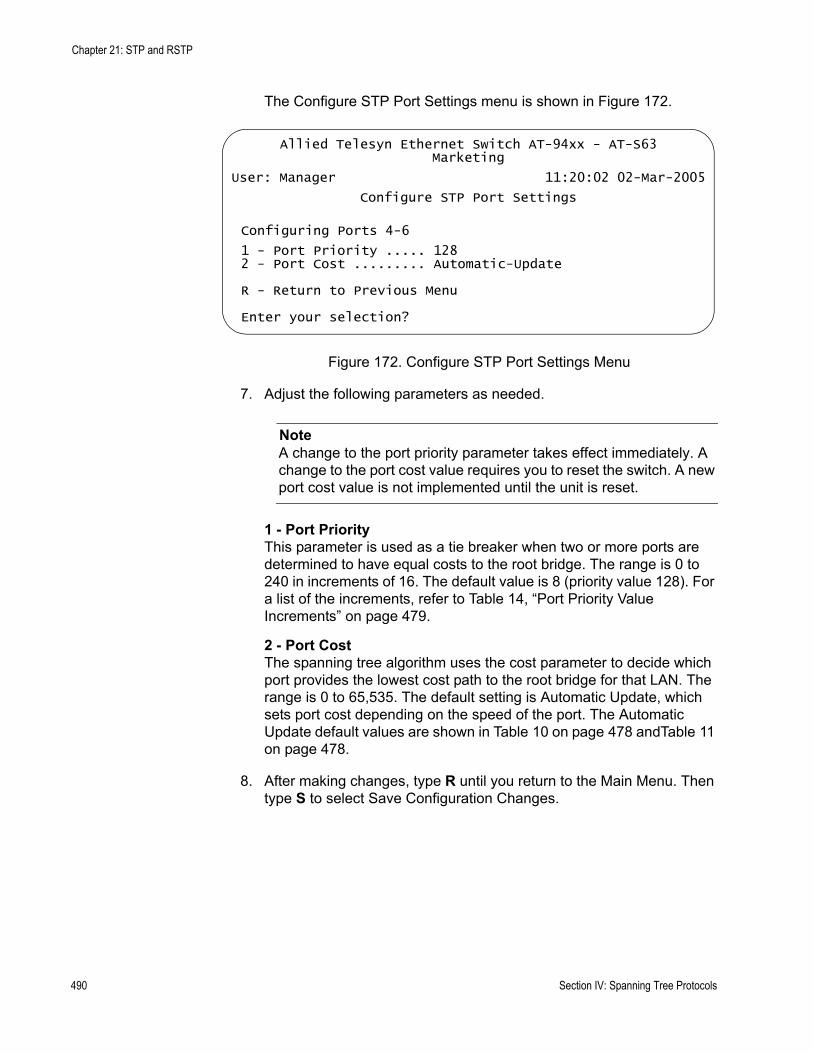
Chapter 21: STP and RSTP
The Configure STP Port Settings menu is shown in Figure 172.
Figure 172. Configure STP Port Settings Menu
7. Adjust the following parameters as needed.
NoteA change to the port priority parameter takes effect immediately. A change to the port cost value requires you to reset the switch. A new port cost value is not implemented until the unit is reset.
1 - Port PriorityThis parameter is used as a tie breaker when two or more ports are determined to have equal costs to the root bridge. The range is 0 to 240 in increments of 16. The default value is 8 (priority value 128). For a list of the increments, refer to Table 14, “Port Priority Value Increments” on page 479.
2 - Port CostThe spanning tree algorithm uses the cost parameter to decide which port provides the lowest cost path to the root bridge for that LAN. The range is 0 to 65,535. The default setting is Automatic Update, which sets port cost depending on the speed of the port. The Automatic Update default values are shown in Table 10 on page 478 andTable 11 on page 478.
8. After making changes, type R until you return to the Main Menu. Then type S to select Save Configuration Changes.
Allied Telesyn Ethernet Switch AT-94xx - AT-S63Marketing
User: Manager 11:20:02 02-Mar-2005
Configure STP Port Settings
Configuring Ports 4-6
1 - Port Priority ..... 1282 - Port Cost ......... Automatic-Update
R - Return to Previous Menu
Enter your selection?
490 Section IV: Spanning Tree Protocols

AT-S63 Management Software Menus Interface User’s Guide
Displaying STPPort Settings
To display STP port settings, perform the following procedure:
1. From the Main Menu, type 3 to select Spanning Tree Configuration.
The Spanning Tree Configuration menu is shown in Figure 169 on page 485.
2. From the Spanning Tree Configuration menu, type 3 to select Configure Active Protocol.
The STP menu is shown in Figure 170 on page 487.
3. From the STP menu, type P to select STP Port Parameters.
The STP Port Parameters menu is shown in Figure 171 on page 489.
4. From the STP Port Parameters menu, type 2 to select Display STP Port Configuration.
The Display STP Port Configuration menu is shown in Figure 173.
Figure 173. Display STP Port Configuration Menu
The Display STP Port Configuration menu displays a table that contains the following columns of information:
Port The port number.
State Current state of the port. The possible states are Enabled or Disabled.
Allied Telesyn Ethernet Switch AT-94xx - AT-S63Marketing
User: Manager 11:20:02 02-Mar-2005
Display STP Port Configuration
Port State Cost Priority-------------------------------------------------------1 Enabled Auto-Update 1282 Enabled Auto-Update 1283 Enabled Auto-Update 1284 Enabled Auto-Update 1285 Enabled Auto-Update 1286 Enabled Auto-Update 1287 Enabled Auto-Update 1288 Enabled Auto-Update 128
N - Next PageU - Update DisplayR - Return to Previous Menu
Enter your selection?
Section IV: Spanning Tree Protocols 491
Chapter 21: STP and RSTP
CostPort cost of the port. The default is Auto-Update.
Priority The number used as a tie breaker when two or more ports have equal costs to the root bridge.
Resetting STP tothe Default
Settings
To reset STP to the default settings, perform the following procedure:
1. From the Main Menu, type 3 to select Spanning Tree Configuration.
The Spanning Tree Configuration menu is shown in Figure 169 on page 485.
2. From the Spanning Tree Configuration menu, type 3 to select Configure Active Protocol.
The STP menu is shown in Figure 170 on page 487.
3. From the STP menu, type D to select Reset STP to Defaults.
The following prompt is displayed:
Do you want to reset STP configuration to default [Yes/No] ->
4. Enter Y for Yes or N for No and press Return.
The STP configuration is reset to the defaults.
492 Section IV: Spanning Tree Protocols

AT-S63 Management Software Menus Interface User’s Guide
Configuring RSTP
This section contains the following procedures:
”Configuring RSTP Bridge Settings”, next“Configuring RSTP Port Settings” on page 495
ConfiguringRSTP Bridge
Settings
This section contains the procedure for configuring a bridge’s RSTP settings.
CautionThe default RSTP parameters are adequate for most networks. Changing them without prior experience and an understanding of how RSTP works might have a negative effect on your network. You should consult the IEEE 802.1w standard before changing any of the RSTP parameters.
To configure the RSTP bridge settings, perform the following procedure:
1. From the Main Menu, type 3 to select Spanning Tree Configuration.
The Spanning Tree Configuration menu is shown in Figure 169 on page 485.
2. From the Spanning Tree Configuration menu, type 3 to select Configure Active Protocol.
The RSTP menu is shown in Figure 174.
Figure 174. RSTP Menu
Allied Telesyn Ethernet Switch AT-94xx - AT-S63Marketing
User: Manager 11:20:02 02-Mar-2005
RSTP Menu
1 - Force Version .......... RSTP2 - Bridge Priority ........ 32768 (In multiples of 4096: 8)3 - Bridge Hello Time ...... 24 - Bridge Forwarding ...... 155 - Bridge Max Age ......... 206 - Bridge Identifier ...... 00:30:84:00:00:00
P - RSTP Port ParametersD - Reset RSTP to Defaults
R - Return to Previous Menu
Enter your selection?
Section IV: Spanning Tree Protocols 493
Chapter 21: STP and RSTP
3. Adjust the following parameters as necessary.
1 - Force VersionThis selection determines whether the bridge operates with RSTP or in an STP-compatible mode. If you select RSTP, the bridge operates all ports in RSTP, except for those ports that receive STP BPDU packets. If you select Force STP Compatible, the bridge operates in RSTP, using the RSTP parameter settings, but it sends only STP BPDU packets out the ports.
2 - Bridge PriorityThe priority number for the bridge. This number is used in determining the root bridge for RSTP. The bridge with the lowest priority number is selected as the root bridge. If two or more bridges have the same priority value, the bridge with the numerically lowest MAC address becomes the root bridge. When a root bridge goes off-line, the bridge with the next priority number automatically takes over as the root bridge. This parameter can be from 0 (zero) to 61,440 in increments of 4096, with 0 being the highest priority. For a list of the increments, refer to Table 9, “Bridge Priority Value Increments” on page 477.
3 - Bridge Hello TimeThe time interval between generating and sending configuration messages by the bridge. This parameter can be from 1 to 10 seconds. The default is 2 seconds.
4 - Bridge ForwardingThe waiting period before a bridge changes to a new state, for example, becomes the new root bridge after the topology changes. If the bridge transitions too soon, not all links may have yet adapted to the change, possibly resulting in a network loop. The range is 4 to 30 seconds. The default is 15 seconds. This setting applies only to ports running in the STP-compatible mode.
5 - Bridge Max AgeThe length of time after which stored bridge protocol data units (BPDUs) are deleted by the bridge. All bridges in a bridged LAN use this aging time to test the age of stored configuration messages called bridge protocol data units (BPDUs). For example, if you use the default 20, all bridges delete current configuration messages after 20 seconds. This parameter can be from 6 to 40 seconds. The default is 20 seconds.
When you select a value for maximum age, observe the following rules:
MaxAge must be greater than (2 x (HelloTime + 1)).
MaxAge must be less than (2 x (ForwardingDelay - 1))
6 - Bridge IdentifierThe MAC address of the bridge. The bridge identifier is used as a tie
494 Section IV: Spanning Tree Protocols

AT-S63 Management Software Menus Interface User’s Guide
breaker in the selection of the root bridge when two or more bridges have the same bridge priority value. This value cannot be changed.
4. After making changes, type R until you return to the Main Menu. Then type S to select Save Configuration Changes.
ConfiguringRSTP Port
Settings
To adjust RSTP port parameters, perform the following procedure:
1. From the Main Menu, type 3 to select Spanning Tree Configuration.
The Spanning Tree Configuration menu is shown in Figure 169 on page 485.
2. From the Spanning Tree Configuration menu, type 3 to select Configure Active Protocol.
The RSTP menu is shown in Figure 170 on page 487.
3. From the Spanning Tree Configuration menu, type 3 to select STP Configuration.
The STP menu is shown in Figure 170 on page 487.
4. From the STP menu, type P to select RSTP Port Parameters.
The RSTP Port Parameters menu is shown in Figure 175.
Figure 175. RSTP Port Parameters Menu
5. Type 1 to select Configure RSTP Port Settings.
The following prompt is displayed:
Starting Port to Configure [1 to 24] ->
6. Enter the number of the port you want to configure. To configure a range of ports, enter the first port of the range.
The following prompt is displayed:
Allied Telesyn Ethernet Switch AT-94xx - AT-S63Marketing
User: Manager 11:20:02 02-Mar-2005
RSTP Port Parameters
1 - Configure RSTP Port Settings2 - Display RSTP Port Configuration3 - Display RSTP Port State
R - Return to Previous Menu
Enter your selection?
Section IV: Spanning Tree Protocols 495
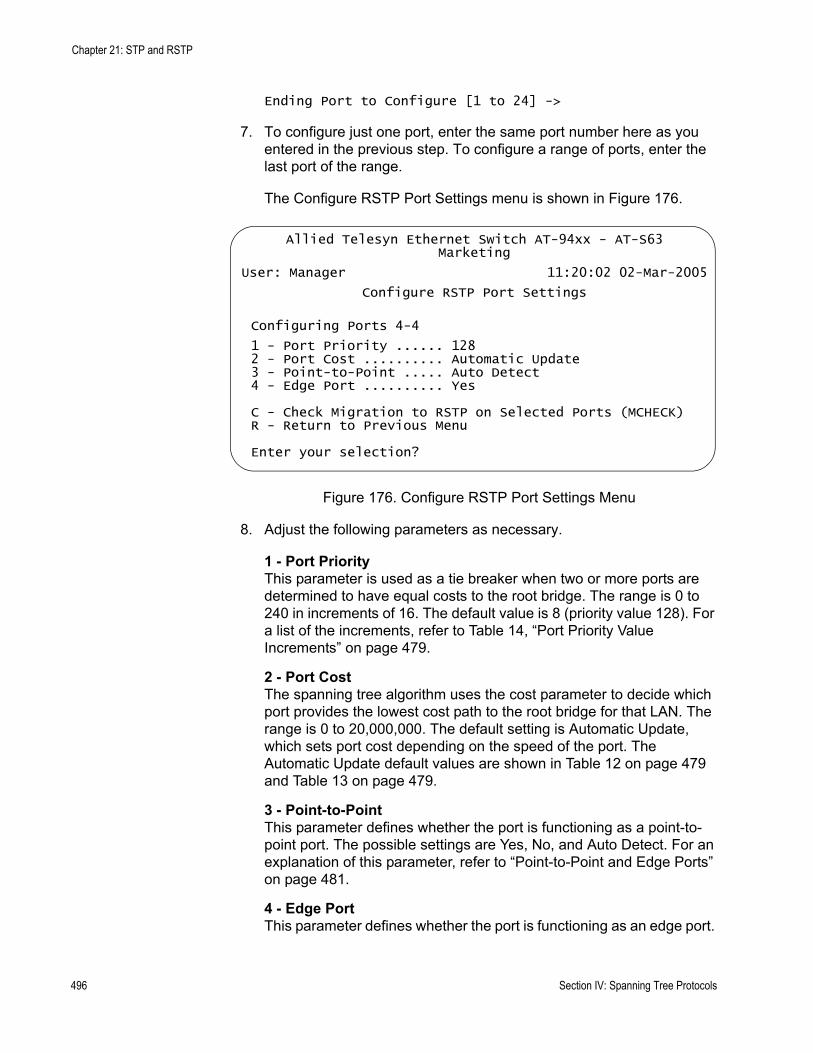
Chapter 21: STP and RSTP
Ending Port to Configure [1 to 24] ->
7. To configure just one port, enter the same port number here as you entered in the previous step. To configure a range of ports, enter the last port of the range.
The Configure RSTP Port Settings menu is shown in Figure 176.
Figure 176. Configure RSTP Port Settings Menu
8. Adjust the following parameters as necessary.
1 - Port PriorityThis parameter is used as a tie breaker when two or more ports are determined to have equal costs to the root bridge. The range is 0 to 240 in increments of 16. The default value is 8 (priority value 128). For a list of the increments, refer to Table 14, “Port Priority Value Increments” on page 479.
2 - Port CostThe spanning tree algorithm uses the cost parameter to decide which port provides the lowest cost path to the root bridge for that LAN. The range is 0 to 20,000,000. The default setting is Automatic Update, which sets port cost depending on the speed of the port. The Automatic Update default values are shown in Table 12 on page 479 and Table 13 on page 479.
3 - Point-to-PointThis parameter defines whether the port is functioning as a point-to-point port. The possible settings are Yes, No, and Auto Detect. For an explanation of this parameter, refer to “Point-to-Point and Edge Ports” on page 481.
4 - Edge PortThis parameter defines whether the port is functioning as an edge port.
Allied Telesyn Ethernet Switch AT-94xx - AT-S63Marketing
User: Manager 11:20:02 02-Mar-2005
Configure RSTP Port Settings
Configuring Ports 4-4
1 - Port Priority ...... 1282 - Port Cost .......... Automatic Update3 - Point-to-Point ..... Auto Detect4 - Edge Port .......... Yes
C - Check Migration to RSTP on Selected Ports (MCHECK)R - Return to Previous Menu
Enter your selection?
496 Section IV: Spanning Tree Protocols
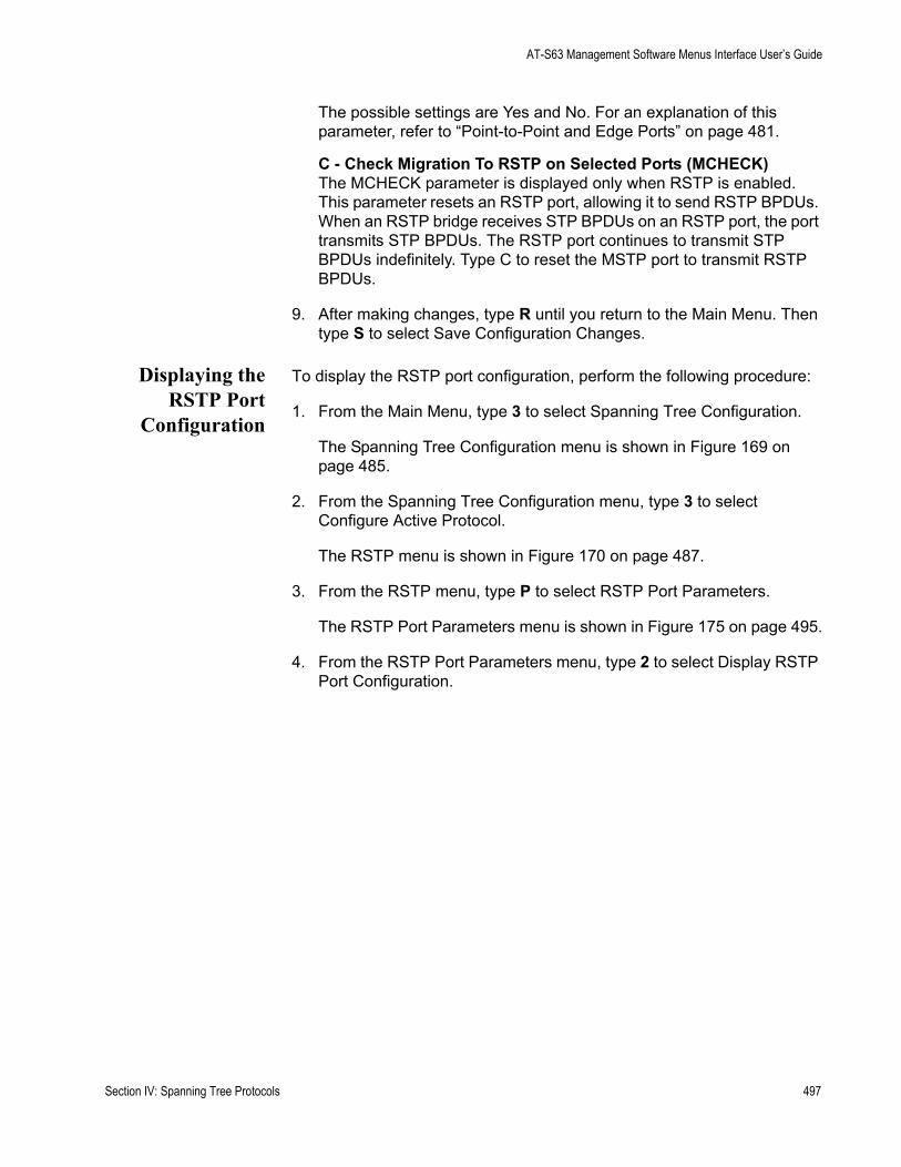
AT-S63 Management Software Menus Interface User’s Guide
The possible settings are Yes and No. For an explanation of this parameter, refer to “Point-to-Point and Edge Ports” on page 481.
C - Check Migration To RSTP on Selected Ports (MCHECK)The MCHECK parameter is displayed only when RSTP is enabled. This parameter resets an RSTP port, allowing it to send RSTP BPDUs. When an RSTP bridge receives STP BPDUs on an RSTP port, the port transmits STP BPDUs. The RSTP port continues to transmit STP BPDUs indefinitely. Type C to reset the MSTP port to transmit RSTP BPDUs.
9. After making changes, type R until you return to the Main Menu. Then type S to select Save Configuration Changes.
Displaying theRSTP Port
Configuration
To display the RSTP port configuration, perform the following procedure:
1. From the Main Menu, type 3 to select Spanning Tree Configuration.
The Spanning Tree Configuration menu is shown in Figure 169 on page 485.
2. From the Spanning Tree Configuration menu, type 3 to select Configure Active Protocol.
The RSTP menu is shown in Figure 170 on page 487.
3. From the RSTP menu, type P to select RSTP Port Parameters.
The RSTP Port Parameters menu is shown in Figure 175 on page 495.
4. From the RSTP Port Parameters menu, type 2 to select Display RSTP Port Configuration.
Section IV: Spanning Tree Protocols 497
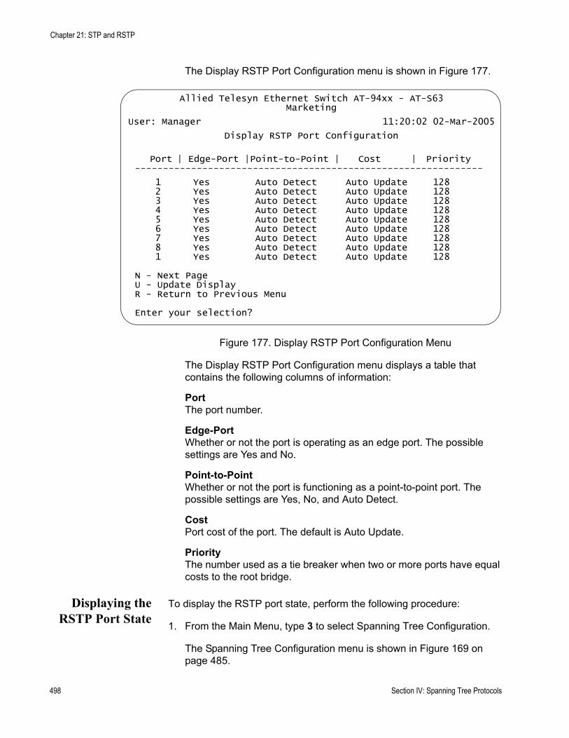
Chapter 21: STP and RSTP
The Display RSTP Port Configuration menu is shown in Figure 177.
Figure 177. Display RSTP Port Configuration Menu
The Display RSTP Port Configuration menu displays a table that contains the following columns of information:
Port The port number.
Edge-Port Whether or not the port is operating as an edge port. The possible settings are Yes and No.
Point-to-Point Whether or not the port is functioning as a point-to-point port. The possible settings are Yes, No, and Auto Detect.
CostPort cost of the port. The default is Auto Update.
Priority The number used as a tie breaker when two or more ports have equal costs to the root bridge.
Displaying theRSTP Port State
To display the RSTP port state, perform the following procedure:
1. From the Main Menu, type 3 to select Spanning Tree Configuration.
The Spanning Tree Configuration menu is shown in Figure 169 on page 485.
Allied Telesyn Ethernet Switch AT-94xx - AT-S63Marketing
User: Manager 11:20:02 02-Mar-2005
Display RSTP Port Configuration
Port | Edge-Port |Point-to-Point | Cost | Priority--------------------------------------------------------------
1 Yes Auto Detect Auto Update 128 2 Yes Auto Detect Auto Update 128 3 Yes Auto Detect Auto Update 128 4 Yes Auto Detect Auto Update 128 5 Yes Auto Detect Auto Update 128 6 Yes Auto Detect Auto Update 128 7 Yes Auto Detect Auto Update 128 8 Yes Auto Detect Auto Update 128 1 Yes Auto Detect Auto Update 128
N - Next PageU - Update DisplayR - Return to Previous Menu
Enter your selection?
498 Section IV: Spanning Tree Protocols
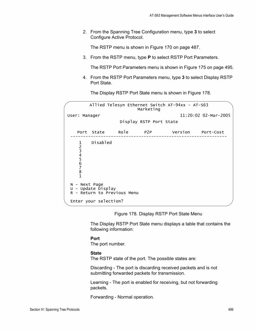
AT-S63 Management Software Menus Interface User’s Guide
2. From the Spanning Tree Configuration menu, type 3 to select Configure Active Protocol.
The RSTP menu is shown in Figure 170 on page 487.
3. From the RSTP menu, type P to select RSTP Port Parameters.
The RSTP Port Parameters menu is shown in Figure 175 on page 495.
4. From the RSTP Port Parameters menu, type 3 to select Display RSTP Port State.
The Display RSTP Port State menu is shown in Figure 178.
Figure 178. Display RSTP Port State Menu
The Display RSTP Port State menu displays a table that contains the following information:
PortThe port number.
StateThe RSTP state of the port. The possible states are:
Discarding - The port is discarding received packets and is not submitting forwarded packets for transmission.
Learning - The port is enabled for receiving, but not forwarding packets.
Forwarding - Normal operation.
Allied Telesyn Ethernet Switch AT-94xx - AT-S63Marketing
User: Manager 11:20:02 02-Mar-2005
Display RSTP Port State
Port State Role P2P Version Port-Cost--------------------------------------------------------------
1 Disabled 2 3 4 5 6 7 8 1
N - Next PageU - Update DisplayR - Return to Previous Menu
Enter your selection?
Section IV: Spanning Tree Protocols 499
Chapter 21: STP and RSTP
Disabled - The port has not established a link with its end node.
RoleThe RSTP role of the port. Possible roles are:
Root - The port that is connected to the root switch, directly or through other switches, with the least path cost.
Alternate - The port offers an alternate path in the direction of the root switch.
Backup - The port on a designated switch that provides a backup for the path provided by the designated port.
Designated - The port on the designated switch for a LAN that has the least cost path to the root switch. This port connects the LAN to the root switch.
P2PWhether or not the port is functioning as a point-to-point port. The possible settings are Yes, No, and Auto-Detect.
VersionWhether the port is operating in RSTP mode or STP-compatible mode.
Port CostThe port cost of the port.
Resetting RSTPto the Default
Settings
To reset RSTP to the default settings, perform the following procedure:
1. From the Main Menu, type 3 to select Spanning Tree Configuration.
The Spanning Tree Configuration menu is shown in Figure 169 on page 485.
2. From the Spanning Tree Configuration menu, type 3 to select Configure Active Protocol.
The RSTP menu is shown in Figure 174 on page 493.
3. From the RSTP Menu, type D to select Reset RSTP to Defaults.
The following prompt is displayed:
Do you want to reset RSTP configuration to default [Yes/No] ->
4. Type Y for Yes or N for No and press Return.
The RSTP configuration is reset to the defaults.
500 Section IV: Spanning Tree Protocols

Chapter 22
MSTP
This chapter provides background information on the Multiple Spanning Tree Protocol (MSTP) and contains procedures on how to adjust spanning tree bridge and port parameters. The sections in this chapter include:
“MSTP Overview” on page 502“Multiple Spanning Tree Instance (MSTI)” on page 503“Selecting MSTP as the Spanning Tree Protocol” on page 516“Configuring MSTP Bridge Settings” on page 517“Configuring the CIST Priority” on page 520“Displaying the CIST Priority” on page 522“Creating, Deleting, and Modifying MSTI IDs” on page 524“Adding, Removing, or Modifying VLAN Associations to MSTI IDs” on page 527“Configuring MSTP Port Settings” on page 532“Displaying the MSTP Port Configuration” on page 538“Displaying the MSTP Port State” on page 540“Resetting MSTP to the Defaults” on page 543
Spanning Tree Protocol (STP) and Rapid Spanning Tree Protocol (RSTP) are described in Chapter 21, “STP and RSTP” on page 475.
Section IV: Spanning Tree Protocols 501
Chapter 22: MSTP
MSTP Overview
As mentioned in Chapter 21, ”STP and RSTP” on page 475, STP and RSTP are referred to as single-instance spanning trees that search for physical loops across all VLANs in a bridged network. When loops are detected, the protocols stop the loops by placing one or more bridge ports in a blocking state.
As explained in “Spanning Tree and VLANs” on page 483, STP and RSTP can result in VLAN fragmentation where VLANs that span multiple bridges are connected together with untagged ports. The untagged ports creating the links can represent a physical loop in the network, which are blocked by spanning tree. The result can be a loss of communication between different parts of the same VLAN.
One way to resolve this, other than by not activating spanning tree on your network, is to link the switches using tagged ports, which can handle traffic from multiple VLANs simultaneously. The drawback to this approach is that the link formed by the tagged ports can create a bottleneck to your Ethernet traffic, resulting in reduced network performance.
Another approach is to use the Multiple Spanning Tree Protocol (MSTP). This spanning tree shares many of the same characteristics as RSTP. It features rapid convergence and has many of the same parameters. But the main difference is that while RSTP, just like STP, supports only a single-instance spanning tree, MSTP supports multiple spanning trees within a network.
The following sections describe some of the terms and concepts relating to MSTP. If you are not familiar with spanning tree or RSTP, you should first review “STP and RSTP Overview” on page 476.
NoteDo not activate MSTP on an AT-9400 Series switch without first familiarizing yourself with the following concepts and guidelines. Unlike STP and RSTP, you cannot activate this spanning tree protocol on a switch without first configuring the protocol parameters.
NoteThe AT-S63 MSTP implementation complies fully with the new IEEE 802.1s standard. Any other vendor’s fully compliant 802.1s implementation is interoperable with the AT-S63 implementation.
502 Section IV: Spanning Tree Protocols
AT-S63 Management Software Menus Interface User’s Guide
Multiple Spanning Tree Instance (MSTI)
The individual spanning trees in MSTP are referred to as Multiple Spanning Tree Instances (MSTIs). A MSTI can span any number of AT-9400 Series switches, and an AT-9400 Series switch can support up to 16 MSTIs at a time.
To create a MSTI, you first assign it a number, referred to as the MSTI ID. The range is 1 to 15. (The switch is shipped with a default MSTI with an MSTI ID of 0. This default spanning tree instance is discussed later in “Common and Internal Spanning Tree (CIST)” on page 511.)
After you have selected an MSTI ID, you need to define the scope of the MSTI by assigning one or more VLANs to it. An instance can contain any number of VLANs, but a VLAN can belong to only one MSTI at a time.
Following are several examples. Figure 179 illustrates two AT-9400 Series switches, each containing the two VLANs Sales and Production. The two parts of each VLAN are connected with a direct link using untagged ports on both switches.
If the switches were running STP or RSTP, one of the links would be blocked because the links constitute a physical loop. Which link would be blocked depends on the STP or RSTP bridge settings.
In Figure 179, the link between the two parts of the Production VLAN is blocked, resulting in a loss of communications between the two parts of
Section IV: Spanning Tree Protocols 503
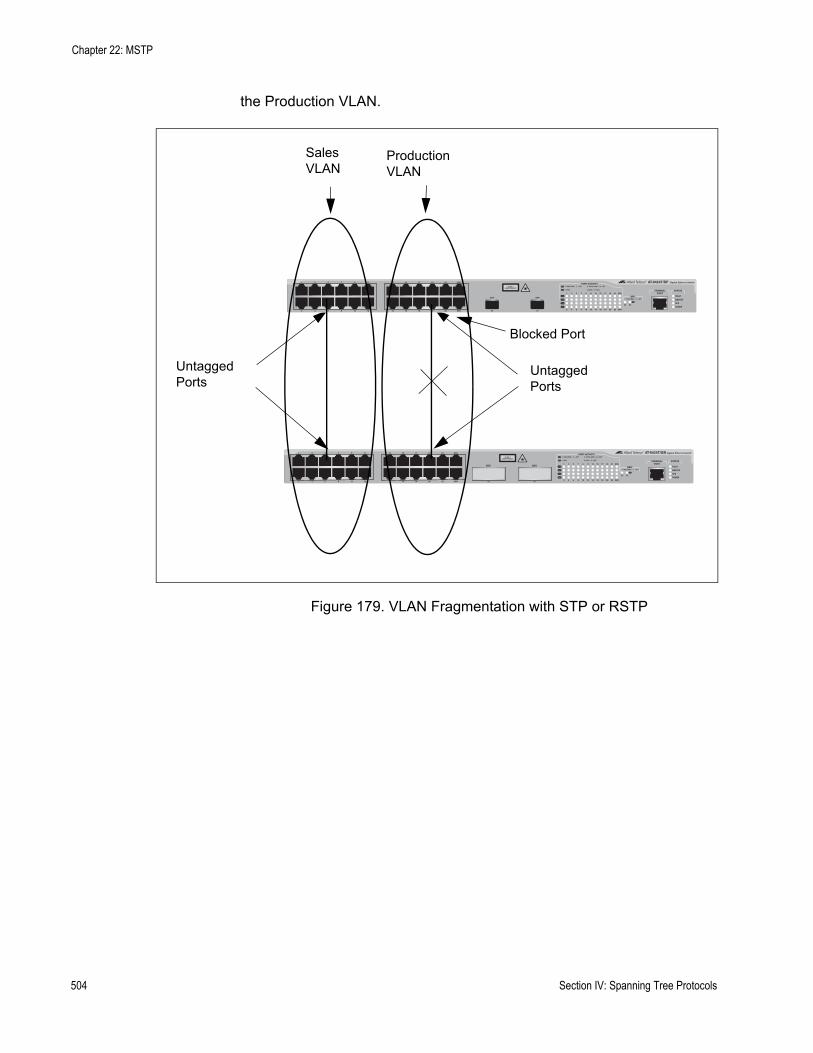
Chapter 22: MSTP
the Production VLAN.
Figure 179. VLAN Fragmentation with STP or RSTP
Blocked Port
FAULT
RPS
MASTER
POWER
CLASS 1LASER PRODUCT
STATUSTERMINALPORT
1 3 5 7 9 11
2 4 6 8 10 12
13 15 17 19 21 23R
14 16 18 20 22 24R
AT-9424T/SP Gigabit Ethernet Switch
1 3 5 7 9 11 13 15 17 19 21 23R
2 4 6 8 10 12 14 16 18 20 22 24R
23 24
L/A
D/C
D/C
L/A
D/C
L/A 1000 LINK / ACT
HDX / COLFDX
10/100 LINK / ACTPORT ACTIVITY
L/A
1000 LINK / ACTSFPSFP
24
SFP
23
FAULT
RPS
MASTER
POWER
GBIC
23
GBIC
24
CLASS 1LASER PRODUCT
STATUSTERMINALPORT
1 3 5 7 9 11
2 4 6 8 10 12
13 15 17 19 21 23R
14 16 18 20 22 24R
AT-9424T/GB Gigabit Ethernet Switch
1 3 5 7 9 11 13 15 17 19 21 23R
2 4 6 8 10 12 14 16 18 20 22 24R
23 24
L/A
D/C
D/C
L/A
D/C
L/A 1000 LINK / ACT
HDX / COLFDX
10/100 LINK / ACTPORT ACTIVITY
L/A
1000 LINK / ACTGBIC
SalesVLAN
ProductionVLAN
UntaggedPorts
UntaggedPorts
504 Section IV: Spanning Tree Protocols
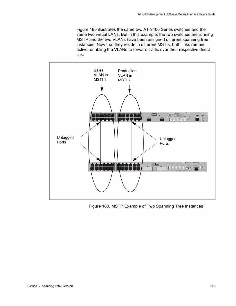
AT-S63 Management Software Menus Interface User’s Guide
Figure 180 illustrates the same two AT-9400 Series switches and the same two virtual LANs. But in this example, the two switches are running MSTP and the two VLANs have been assigned different spanning tree instances. Now that they reside in different MSTIs, both links remain active, enabling the VLANs to forward traffic over their respective direct link.
Figure 180. MSTP Example of Two Spanning Tree Instances
FAULT
RPS
MASTER
POWER
CLASS 1LASER PRODUCT
STATUSTERMINALPORT
1 3 5 7 9 11
2 4 6 8 10 12
13 15 17 19 21 23R
14 16 18 20 22 24R
AT-9424T/SP Gigabit Ethernet Switch
1 3 5 7 9 11 13 15 17 19 21 23R
2 4 6 8 10 12 14 16 18 20 22 24R
23 24
L/A
D/C
D/C
L/A
D/C
L/A 1000 LINK / ACT
HDX / COLFDX
10/100 LINK / ACTPORT ACTIVITY
L/A
1000 LINK / ACTSFPSFP
24
SFP
23
FAULT
RPS
MASTER
POWER
GBIC
23
GBIC
24
CLASS 1LASER PRODUCT
STATUSTERMINALPORT
1 3 5 7 9 11
2 4 6 8 10 12
13 15 17 19 21 23R
14 16 18 20 22 24R
AT-9424T/GB Gigabit Ethernet Switch
1 3 5 7 9 11 13 15 17 19 21 23R
2 4 6 8 10 12 14 16 18 20 22 24R
23 24
L/A
D/C
D/C
L/A
D/C
L/A 1000 LINK / ACT
HDX / COLFDX
10/100 LINK / ACTPORT ACTIVITY
L/A
1000 LINK / ACTGBIC
SalesVLAN inMSTI 1
ProductionVLAN inMSTI 2
UntaggedPorts
UntaggedPorts
Section IV: Spanning Tree Protocols 505

Chapter 22: MSTP
A MSTI can contain more than one VLAN. This is illustrated in Figure 181 where there are two AT-9400 Series switches with four VLANs. There are two MSTIs, each containing two VLANs. MSTI 1 contains the Sales and Presales VLANs and MSTI 2 contains the Design and Engineering VLANs.
Figure 181. Multiple VLANs in a MSTI
In this example, because an MSTI contains more than one VLAN, the links between the VLAN parts is made with tagged, not untagged, ports so that they can carry traffic from more than one virtual LAN. Referring again to Figure 181, the tagged link in MSTI 1 is carrying traffic for both the Presales and Sales VLANs while the tagged link in MSTI 2 is carrying traffic for the Design and Engineering VLANs.
FAULT
RPS
MASTER
POWER
CLASS 1LASER PRODUCT
STATUSTERMINALPORT
1 3 5 7 9 11
2 4 6 8 10 12
13 15 17 19 21 23R
14 16 18 20 22 24R
AT-9424T/SP Gigabit Ethernet Switch
1 3 5 7 9 11 13 15 17 19 21 23R
2 4 6 8 10 12 14 16 18 20 22 24R
23 24
L/A
D/C
D/C
L/A
D/C
L/A 1000 LINK / ACT
HDX / COLFDX
10/100 LINK / ACTPORT ACTIVITY
L/A
1000 LINK / ACTSFPSFP
24
SFP
23
FAULT
RPS
MASTER
POWER
GBIC
23
GBIC
24
CLASS 1LASER PRODUCT
STATUSTERMINALPORT
1 3 5 7 9 11
2 4 6 8 10 12
13 15 17 19 21 23R
14 16 18 20 22 24R
AT-9424T/GB Gigabit Ethernet Switch
1 3 5 7 9 11 13 15 17 19 21 23R
2 4 6 8 10 12 14 16 18 20 22 24R
23 24
L/A
D/C
D/C
L/A
D/C
L/A 1000 LINK / ACT
HDX / COLFDX
10/100 LINK / ACTPORT ACTIVITY
L/A
1000 LINK / ACTGBIC
MSTI 1 MSTI 2
TaggedPorts Tagged
Ports
PresalesVLAN
SalesVLAN
DesignVLAN
EngineeringVLAN
506 Section IV: Spanning Tree Protocols
AT-S63 Management Software Menus Interface User’s Guide
MSTI Guidelines Following are several guidelines to keep in mind about MSTIs:
An AT-9400 Series switch can support up to 16 spanning tree instances, including the CIST, at a time.A MSTI can contain any number of VLANs.A VLAN can belong to only one MSTI at a time.A switch port can belong to more than one spanning tree instance at a time. This allows you to assign a port as an untagged and tagged member of VLANs that belong to different MSTI’s. What makes this possible is a port’s ability to be in different MSTP states for different MSTI’s simultaneously. For example, a port can be in the MSTP blocking state for one MSTI and the forwarding state for another spanning tree instance.A router or Layer 3 network device is required to forward traffic between different VLANs.
VLAN and MSTIAssociations
Part of the task to configuring MSTP involves assigning VLANs to spanning tree instances. The mapping of VLANs to MSTIs is called associations. A VLAN, either port-based or tagged, can belong to only one instance at a time, but an instance can contain any number of VLANs.
Ports in MultipleMSTIs
An AT-9400 Series switch allows a port to be a member of more than one MSTI at a time. This can happen if a port is a tagged member of one or more VLANs and the VLANs are assigned to different MSTI’s. If this occurs, a port might be required to operate in different spanning tree states simultaneously, depending on the requirements of the MSTIs. For example, a port that is a member of two VLANs assigned to two different MSTIs might operate in the forwarding state in one MSTI and in the blocking state in the other.
When you configure a port’s MSTI parameter settings you will notice that the parameters are divided into two groups. The first group is referred to as generic parameters. These are set just once on a port, regardless of the number of MSTI’s where a port happens to be a member. One of these parameters is the external path cost, which sets the operating cost of the port in situations where it is connected to a device that is outside its region. A port can have only one external path cost even if it belongs to multiple MSTI’s. Other generic parameters designate whether the port is an edge port or a point-to-point port.
The second group can be applied independently on a port for each MSTI where the port is a member. One of the parameters is the internal path cost. This parameter specifies the port’s operating cost if it is connected to a bridge that is a part of the same MSTP region. You can give a port a different internal path cost for each MSTI where it is a member. This group also has a parameter for setting port priority, used as a tie breaker when two or more ports have equal costs to a regional root bridge. As with the internal path cost, a port can have a different priority value for each of its MSTI’s.
Section IV: Spanning Tree Protocols 507
Chapter 22: MSTP
MultipleSpanning Tree
Regions
Another important concept of MSTP is regions. A MSTP region is defined as a group of bridges that share exactly the same MSTI characteristics. Those characteristics are:
Configuration nameRevision numberVLANsVLAN to MSTI ID associations
A configuration name is a name you assign to a region to help you identify it. You must assign each bridge in a region exactly the same name; even the same upper and lowercase lettering. Identifying the regions in your network is easier if you choose names that are characteristic of the functions of the nodes and bridges of the region. Examples are Sales Region and Engineering Region.
The revision number is an arbitrary number you assign to a region. This number can be used to keep track of the revision level of a region’s configuration. For example, you might use this value to maintain the number of times you revise a particular MSTP region. It is not important that you maintain this number, only that each bridge in a region have the same number.
The bridges of a particular region must also have the same VLANs. The names of the VLANs and the VIDs must be same on all bridges of a region.
Finally, the VLANs in the bridges must be associated to the same MSTIs.
If any of the above information is different on two bridges, MSTP does consider the bridges as residing in different regions.
508 Section IV: Spanning Tree Protocols
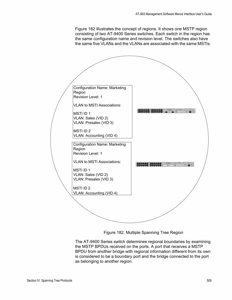
AT-S63 Management Software Menus Interface User’s Guide
Figure 182 illustrates the concept of regions. It shows one MSTP region consisting of two AT-9400 Series switches. Each switch in the region has the same configuration name and revision level. The switches also have the same five VLANs and the VLANs are associated with the same MSTIs.
Figure 182. Multiple Spanning Tree Region
The AT-9400 Series switch determines regional boundaries by examining the MSTP BPDUs received on the ports. A port that receives a MSTP BPDU from another bridge with regional information different from its own is considered to be a boundary port and the bridge connected to the port as belonging to another region.
FAULT
RPS
MASTER
POWER
GBIC
23
GBIC
24
CLASS 1LASER PRODUCT
STATUSTERMINALPORT
1 3 5 7 9 11
2 4 6 8 10 12
13 15 17 19 21 23R
14 16 18 20 22 24R
AT-9424T/GB Gigabit Ethernet Switch
1 3 5 7 9 11 13 15 17 19 21 23R
2 4 6 8 10 12 14 16 18 20 22 24R
23 24
L/A
D/C
D/C
L/A
D/C
L/A 1000 LINK / ACT
HDX / COLFDX
10/100 LINK / ACTPORT ACTIVITY
L/A
1000 LINK / ACTGBIC
Configuration Name: Marketing RegionRevision Level: 1
VLAN to MSTI Associations:
MSTI ID 1VLAN: Sales (VID 2)VLAN: Presales (VID 3)
MSTI ID 2VLAN: Accounting (VID 4)
Configuration Name: Marketing RegionRevision Level: 1
VLAN to MSTI Associations:
MSTI ID 1VLAN: Sales (VID 2)VLAN: Presales (VID 3)
MSTI ID 2VLAN: Accounting (VID 4)
FAULT
RPS
MASTER
POWER
CLASS 1LASER PRODUCT
STATUSTERMINALPORT
1 3 5 7 9 11
2 4 6 8 10 12
13 15 17 19 21 23R
14 16 18 20 22 24R
AT-9424T/SP Gigabit Ethernet Switch
1 3 5 7 9 11 13 15 17 19 21 23R
2 4 6 8 10 12 14 16 18 20 22 24R
23 24
L/A
D/C
D/C
L/A
D/C
L/A 1000 LINK / ACT
HDX / COLFDX
10/100 LINK / ACTPORT ACTIVITY
L/A
1000 LINK / ACTSFPSFP
24
SFP
23
Section IV: Spanning Tree Protocols 509
Chapter 22: MSTP
The same is true for any ports connected to bridges running the single-instance spanning tree STP or RSTP. Those ports are also considered as part of another region.
Each MSTI functions as an independent spanning tree within a region. Consequently, each MSTI must have a root bridge to locate physical loops within the spanning tree instance. An MSTI’s root bridge is called a regional root. The MSTIs within a region may share the same regional root or they can have different regional roots.
A regional root for an MSTI must be within the region where the MSTI is located. An MSTI cannot have a regional root that is outside its region.
A regional root is selected by a combination of the MSTI priority value and the bridge’s MAC address. The MSTI priority is analogous to the RSTP bridge priority value. Where they differ is that while the RSTP bridge priority is used to determine the root bridge for an entire bridged network, MSTI priority is used only to determine the regional root for a particular MSTI.
The range for this parameter is the same as the RSTP bridge priority; from 0 to 61,440 in sixteen increments of 4,096. To set the parameter, you specify the increment that represents the desired MSTI priority value. Table 14 on page 479 lists the increments.
Region Guidelines
Following are several points to remember about regions.
A network can contain any number of regions and a region can contain any number of AT-9400 Series switches. An AT-9400 Series switch can belong to only one region at a time. A region can contain any number of VLANs.All of the bridges in a region must have the same configuration name, revision level, VLANs, and VLAN to MSTI associations.An MSTI cannot span multiple regions.Each MSTI must have a regional root for locating loops in the instance. MSTIs can share the same regional root or have different roots. A regional root is determined by the MSTI priority value and a bridge’s MAC address.The regional root of a MSTI must be in the same region as the MSTI.
510 Section IV: Spanning Tree Protocols
AT-S63 Management Software Menus Interface User’s Guide
Common and Internal Spanning Tree (CIST)
MSTP has a default spanning tree instance called the Common and Internal Spanning Tree (CIST). This instance has an MSTI ID of 0.
This instance has unique features and functions that make it different from the MSTIs that you create yourself. First, you cannot delete this instance and you cannot change its MSTI ID.
Second, when you create a new port-based or tagged VLAN, it is by default associated with the CIST and is automatically given an MSTI ID of 0. The Default_VLAN is also associated by default with CIST.
Another critical difference is that when you assign a VLAN to another MSTI, it still partially remains a member of CIST. This is because CIST is used by MSTP to communicate with other MSTP regions and with any RSTP and STP single-instance spanning trees in the network. MSTP uses CIST to participate in the creation of a spanning tree between different regions and between regions and single-instance spanning tree, to form one spanning tree for the entire bridged network.
MSTP uses CIST to form the spanning tree of an entire bridged network because CIST can cross regional boundaries, while a MSTI cannot. If a port is a boundary port, that is, if it is connected to another region, that port automatically belongs solely to CIST, even if it was assigned to an MSTI, because only CIST is active outside of a region.
As mentioned earlier, every MSTI must have a root bridge, referred to as a regional root, in order to locate loops that might exist within the instance. CIST must also have a regional root. However, the CIST regional root communicates with the other MSTP regions and single-instance spanning trees in the bridged network.
The CIST regional root is set with the CIST Priority parameter. This parameter, which functions similar to the RSTP bridge priority value, selects the root bridge for the entire bridged network. If an AT-9400 Series switch has the lowest CIST Priority value among all the spanning tree bridges, it functions as the root bridge for all the MSTP regions and STP and RSTP single-instance spanning trees in the network.
MSTP with STP and RSTP
MSTP is fully compatible with STP and RSTP. If a port on an AT-9400 Series switch running MSTP receives STP BPDUs, the port sends only STP BPDU packets. If a port receives RSTP BPDUs, the port sends MSTP BPDUs because RSTP can process MSTP BPDUs.
A port connected to a bridge running STP or RSTP is considered to be a boundary port of the MSTP region and the bridge as belonging to a different region.
Section IV: Spanning Tree Protocols 511
Chapter 22: MSTP
An MSTP region can be considered as a virtual bridge. The implication is that other MSTP regions and STP and RSTP single-instance spanning trees cannot discern the topology or constitution of a MSTP region. The only bridge they are aware of is the regional root of the CIST instance.
Summary ofGuidelines
Careful planning is essential for the successful implementation of MSTP. This section reviews all the rules and guidelines mentioned in earlier sections, and contains a few new ones:
An AT-9400 Series switch can support up to 16 spanning tree instances, including the CIST, at a time.A MSTI can contain any number of VLANs.A VLAN can belong to only one MSTI at a time.An MSTI ID can be from 1 to 15.The CIST ID is 0. You cannot change this value.A switch port can belong to more than one spanning tree instance at a time. This allows you to assign a port as an untagged and tagged member of VLANs that belong to different MSTIs. What makes this possible is a port’s ability to be in different MSTP states for different MSTIs simultaneously. For example, a port can be in the MSTP blocking state for one MSTI and the forwarding state for another spanning tree instance.A router or Layer 3 network device is required to forward traffic between VLANs.A network can contain any number of regions and a region can contain any number of AT-9400 Series switches. An AT-9400 Series switch can belong to only one region at a time. A region can contain any number of VLANs.All of the bridges in a region must have the same configuration name, revision level, VLANs, and VLAN to MSTI associations.An MSTI cannot span multiple regions.Each MSTI must have a regional root for locating loops in the instance. MSTIs can share the same regional root or have different roots. A regional root is determined by the MSTI priority value and a bridge’s MAC address.The regional root of a MSTI must be in the same region as the MSTI.The CIST must have a regional root for communicating with other regions and single-instance spanning trees.MSTP is compatible with STP and RSTP.A port transmits CIST information even when it is associated with another MSTI ID. However, in determining network loops, MSTI takes precedence over CIST. (This is explained more in “Associating VLANs to MSTIs” on page 513.
512 Section IV: Spanning Tree Protocols
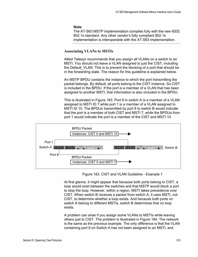
AT-S63 Management Software Menus Interface User’s Guide
NoteThe AT-S63 MSTP implementation complies fully with the new IEEE 802.1s standard. Any other vendor’s fully compliant 802.1s implementation is interoperable with the AT-S63 implementation.
Associating VLANs to MSTIs
Allied Telesyn recommends that you assign all VLANs on a switch to an MSTI. You should not leave a VLAN assigned to just the CIST, including the Default_VLAN. This is to prevent the blocking of a port that should be in the forwarding state. The reason for this guideline is explained below.
An MSTP BPDU contains the instance to which the port transmitting the packet belongs. By default, all ports belong to the CIST instance. So CIST is included in the BPDU. If the port is a member of a VLAN that has been assigned to another MSTI, that information is also included in the BPDU.
This is illustrated in Figure 183. Port 8 in switch A is a member of a VLAN assigned to MSTI ID 7 while port 1 is a member of a VLAN assigned to MSTI ID 10. The BPDUs transmitted by port 8 to switch B would indicate that the port is a member of both CIST and MSTI 7, while the BPDUs from port 1 would indicate the port is a member of the CIST and MSTI 10.
Figure 183. CIST and VLAN Guideline - Example 1
At first glance, it might appear that because both ports belong to CIST, a loop would exist between the switches and that MSTP would block a port to stop the loop. However, within a region, MSTI takes precedence over CIST. When switch B receives a packet from switch A, it uses MSTI, not CIST, to determine whether a loop exists. And because both ports on switch A belong to different MSTIs, switch B determines that no loop exists.
A problem can arise if you assign some VLANs to MSTIs while leaving others just to CIST. The problem is illustrated in Figure 184. The network is the same as the previous example. The only difference is that the VLAN containing port 8 on Switch A has not been assigned to an MSTI, and
FAULT
RPS
MASTER
POWER
CLASS 1LASER PRODUCT
STATUSTERMINALPORT
1 3 5 7 9 11
2 4 6 8 10 12
13 15 17 19 21 23R
14 16 18 20 22 24R
AT-9424T/SP Gigabit Ethernet Switch
1 3 5 7 9 11 13 15 17 19 21 23R
2 4 6 8 10 12 14 16 18 20 22 24R
23 24
L/A
D/C
D/C
L/A
D/C
L/A 1000 LINK / ACT
HDX / COLFDX
10/100 LINK / ACTPORT ACTIVITY
L/A
1000 LINK / ACTSFPSFP
24
SFP
23
Switch A Switch B
Port 1
Port 8BPDU Packet
BPDU PacketInstances: CIST 0 and MSTI 10
Instances: CIST 0 and MSTI 7
Section IV: Spanning Tree Protocols 513
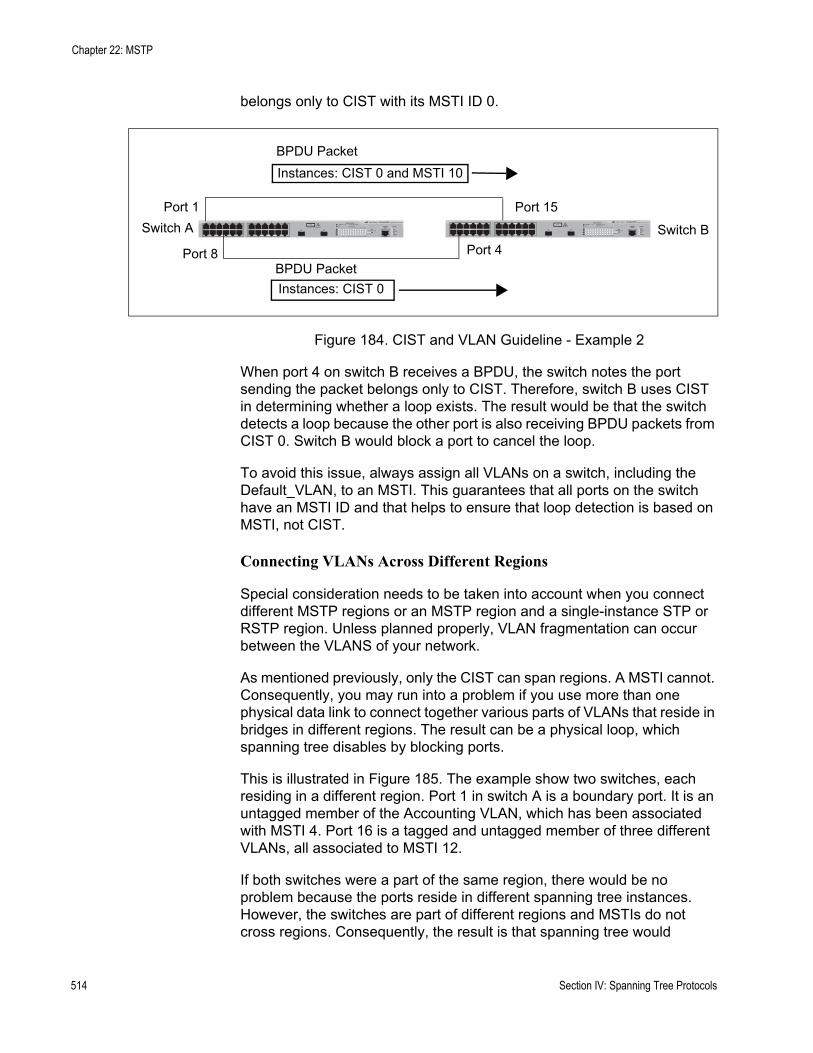
Chapter 22: MSTP
belongs only to CIST with its MSTI ID 0.
Figure 184. CIST and VLAN Guideline - Example 2
When port 4 on switch B receives a BPDU, the switch notes the port sending the packet belongs only to CIST. Therefore, switch B uses CIST in determining whether a loop exists. The result would be that the switch detects a loop because the other port is also receiving BPDU packets from CIST 0. Switch B would block a port to cancel the loop.
To avoid this issue, always assign all VLANs on a switch, including the Default_VLAN, to an MSTI. This guarantees that all ports on the switch have an MSTI ID and that helps to ensure that loop detection is based on MSTI, not CIST.
Connecting VLANs Across Different Regions
Special consideration needs to be taken into account when you connect different MSTP regions or an MSTP region and a single-instance STP or RSTP region. Unless planned properly, VLAN fragmentation can occur between the VLANS of your network.
As mentioned previously, only the CIST can span regions. A MSTI cannot. Consequently, you may run into a problem if you use more than one physical data link to connect together various parts of VLANs that reside in bridges in different regions. The result can be a physical loop, which spanning tree disables by blocking ports.
This is illustrated in Figure 185. The example show two switches, each residing in a different region. Port 1 in switch A is a boundary port. It is an untagged member of the Accounting VLAN, which has been associated with MSTI 4. Port 16 is a tagged and untagged member of three different VLANs, all associated to MSTI 12.
If both switches were a part of the same region, there would be no problem because the ports reside in different spanning tree instances. However, the switches are part of different regions and MSTIs do not cross regions. Consequently, the result is that spanning tree would
FAULT
RPS
MASTER
POWER
CLASS 1LASER PRODUCT
STATUSTERMINALPORT
1 3 5 7 9 11
2 4 6 8 10 12
13 15 17 19 21 23R
14 16 18 20 22 24R
AT-9424T/SP Gigabit Ethernet Switch
1 3 5 7 9 11 13 15 17 19 21 23R
2 4 6 8 10 12 14 16 18 20 22 24R
23 24
L/A
D/C
D/C
L/A
D/C
L/A 1000 LINK / ACT
HDX / COLFDX
10/100 LINK / ACTPORT ACTIVITY
L/A
1000 LINK / ACTSFPSFP
24
SFP
23
Switch A Switch B
Port 1
Port 8BPDU Packet
BPDU PacketInstances: CIST 0 and MSTI 10
Instances: CIST 0
Port 15
Port 4
514 Section IV: Spanning Tree Protocols
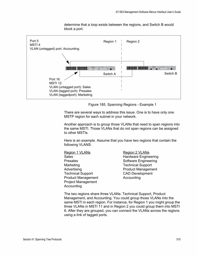
AT-S63 Management Software Menus Interface User’s Guide
determine that a loop exists between the regions, and Switch B would block a port.
Figure 185. Spanning Regions - Example 1
There are several ways to address this issue. One is to have only one MSTP region for each subnet in your network.
Another approach is to group those VLANs that need to span regions into the same MSTI. Those VLANs that do not span regions can be assigned to other MSTIs.
Here is an example. Assume that you have two regions that contain the following VLANS:
Region 1 VLANs Region 2 VLANsSales Hardware EngineeringPresales Software EngineeringMarketing Technical SupportAdvertising Product ManagementTechnical Support CAD DevelopmentProduct Management AccountingProject ManagementAccounting
The two regions share three VLANs: Technical Support, Product Management, and Accounting. You could group those VLANs into the same MSTI in each region. For instance, for Region 1 you might group the three VLANs in MSTI 11 and in Region 2 you could group them into MSTI 6. After they are grouped, you can connect the VLANs across the regions using a link of tagged ports.
Region 1 Region 2
Switch A Switch B
FAULT
RPS
MASTER
POWER
CLASS 1LASER PRODUCT
STATUSTERMINALPORT
1 3 5 7 9 11
2 4 6 8 10 12
13 15 17 19 21 23R
14 16 18 20 22 24R
AT-9424T/SP Gigabit Ethernet Switch
1 3 5 7 9 11 13 15 17 19 21 23R
2 4 6 8 10 12 14 16 18 20 22 24R
23 24
L/A
D/C
D/C
L/A
D/C
L/A 1000 LINK / ACT
HDX / COLFDX
10/100 LINK / ACTPORT ACTIVITY
L/A
1000 LINK / ACTSFPSFP
24
SFP
23
FAULT
RPS
MASTER
POWER
GBIC
23
GBIC
24
CLASS 1LASER PRODUCT
STATUSTERMINALPORT
1 3 5 7 9 11
2 4 6 8 10 12
13 15 17 19 21 23R
14 16 18 20 22 24R
AT-9424T/GB Gigabit Ethernet Switch
1 3 5 7 9 11 13 15 17 19 21 23R
2 4 6 8 10 12 14 16 18 20 22 24R
23 24
L/A
D/C
D/C
L/A
D/C
L/A 1000 LINK / ACT
HDX / COLFDX
10/100 LINK / ACTPORT ACTIVITY
L/A
1000 LINK / ACTGBIC
Port 5MSTI 4VLAN (untagged) port: Accounting
Port 16MSTI 12VLAN (untagged port): SalesVLAN (tagged port): PresalesVLAN (taggedport): Marketing
Section IV: Spanning Tree Protocols 515

Chapter 22: MSTP
Selecting MSTP as the Spanning Tree Protocol
To select and activate MSTP as the spanning tree protocol, or to disable spanning tree, perform the following procedure:
1. From the Main Menu, type 3 to select Spanning Tree Configuration.
The Spanning Tree Configuration menu is shown in Figure 169 on page 485.
2. To change the active version of spanning tree on the switch, type 2 to select Active Protocol Version.
The following prompt is displayed:
Enter new value (S-STP, R-RSTP, M-MSTP):
3. Type M to select MSTP.
NoteA change to the active spanning tree is automatically saved on the switch.
4. To enable or disable spanning tree, type 1 to select Spanning Tree Status.
The following prompt is displayed:
Enter new value (E-Enable, D-Disable):
5. Type E to enable spanning tree or D to disable it. The default is disabled.
6. After making changes, type R until you return to the Main Menu. Then type S to select Save Configuration Changes.
516 Section IV: Spanning Tree Protocols
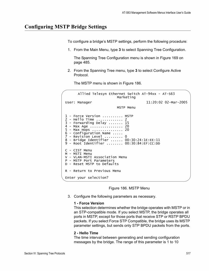
AT-S63 Management Software Menus Interface User’s Guide
Configuring MSTP Bridge Settings
To configure a bridge’s MSTP settings, perform the following procedure:
1. From the Main Menu, type 3 to select Spanning Tree Configuration.
The Spanning Tree Configuration menu is shown in Figure 169 on page 485.
2. From the Spanning Tree menu, type 3 to select Configure Active Protocol.
The MSTP menu is shown in Figure 186.
Figure 186. MSTP Menu
3. Configure the following parameters as necessary.
1 - Force VersionThis selection determines whether the bridge operates with MSTP or in an STP-compatible mode. If you select MSTP, the bridge operates all ports in MSTP, except for those ports that receive STP or RSTP BPDU packets. If you select Force STP Compatible, the bridge uses its MSTP parameter settings, but sends only STP BPDU packets from the ports.
2 - Hello TimeThe time interval between generating and sending configuration messages by the bridge. The range of this parameter is 1 to 10
Allied Telesyn Ethernet Switch AT-94xx - AT-S63Marketing
User: Manager 11:20:02 02-Mar-2005
MSTP Menu
1 - Force Version .......... MSTP2 - Hello Time ............. 23 - Forwarding Delay ....... 154 - Max Age ................ 205 - Max Hops ............... 206 - Configuration Name ..... 7 - Revision Level ......... 08 - Bridge Identifier ...... 00:30:24:1E:EE:119 - Root Identifier ........ 00:30:84:EF:CC:DD
C - CIST MenuM - MSTI MenuV - VLAN-MSTI Association MenuP - MSTP Port ParametersD - Reset MSTP to Defaults
R - Return to Previous Menu
Enter your selection?
Section IV: Spanning Tree Protocols 517
Chapter 22: MSTP
seconds. The default is 2 seconds. This value is active only if the bridge is selected as the root bridge of the network.
3 - Forwarding DelayThe waiting period before a bridge changes to a new state, for example, becomes the new root bridge after the topology changes. If the bridge transitions too soon, not all links may have yet adapted to the change, possibly resulting in a network loop. The range is 4 to 30 seconds. The default is 15 seconds. This setting applies only to ports running in the STP-compatible mode.
4 - Max AgeThe length of time after which stored bridge protocol data units (BPDUs) are deleted by the bridge. This parameter applies only if the bridged network contains an STP or RSTP single-instance spanning tree. Otherwise, the bridges use the Max Hop counter to delete BPDUs.
All bridges in a single-instance bridged LAN use this aging time to test the age of stored configuration messages called bridge protocol data units (BPDUs). For example, if you use the default of 20, all bridges delete current configuration messages after 20 seconds. The range of this parameter is 6 to 40 seconds. The default is 20 seconds.
When you select a value for maximum age, observer the following rules:
MaxAge must be greater than (2 x (HelloTime + 1)).
MaxAge must be less than (2 x (ForwardingDelay - 1))
5 - Max HopsMSTP regions use this parameter to discard BPDUs. The Max Hop counter in a BPDU is decremented every time the BPDU crosses an MSTP region boundary. After the counter reaches zero, the BPDU is deleted.
6 - Configuration NameThe name of the MSTP region. The range is 0 (zero) to 32 alphanumeric characters in length. The name, which is case sensitive, must be the same on all bridges in a region. Examples include Sales Region and Production Region.
7 - Revision LevelThe revision level of an MSTP region. The range is 0 (zero) to 255. This is an arbitrary number that you assign to a region. The revision level must be the same on all bridges in a region. Different regions can have the same revision level without conflict.
8 - Bridge IdentifierThe MAC address of the bridge. The bridge identifier is used as a tie breaker in the selection of a root bridge when two or more bridges have the same bridge priority value. This value cannot be changed.
518 Section IV: Spanning Tree Protocols
AT-S63 Management Software Menus Interface User’s Guide
9 - Root IdentifierIf this MAC address is the same as the bridge’s MAC address, then the switch is also functioning as a root bridge. If the two MAC addresses are different, then a different switch is functioning as the root bridge. You cannot change this parameter. This parameter is only displayed with MSTP is enabled.
NoteSelection C, CIST menu, is described in “Configuring the CIST Priority,” next.
Selection M, MSTI menu, is described in “Creating, Deleting, and Modifying MSTI IDs” on page 524.
Selection V, VLAN-MSTI Association menu, is described in “Adding, Removing, or Modifying VLAN Associations to MSTI IDs” on page 527.
Selection P, MSTP Port Parameters, is described in “Configuring MSTP Port Settings” on page 532.
Selection D, Reset MSTP to Defaults, is described in “Resetting MSTP to the Defaults” on page 543.
4. After making changes, type R until you return to the Main Menu. Then type S to select Save Configuration Changes.
Section IV: Spanning Tree Protocols 519

Chapter 22: MSTP
Configuring the CIST Priority
This procedure explains how to adjust the bridge’s CIST priority.
To change the CIST priority, perform the following procedure:
1. From the Main Menu, type 3 to select Spanning Tree Configuration.
The Spanning Tree Configuration menu is shown in Figure 169 on page 485.
2. From the Spanning Tree Configuration menu, type 3 to select Configure Active Protocol.
The MSTP menu is shown in Figure 186 on page 517.
3. From the MSTP menu, type C to select CIST menu.
The CIST menu is shown in Figure 187.
Figure 187. CIST Menu
The CIST Priority field in the menu displays the current value for this MSTP parameter. This number is used in determining the root bridge of the network spanning tree. This number is analogous to the RSTP bridge priority value. The bridge in the network with the lowest priority number is selected as the root bridge. If two or more bridges have the same bridge or CIST priority values, the bridge with the numerically lowest MAC address becomes the root bridge.
The Associated VLANs field displays the VIDs of the VLANs that are currently associated with CIST and have not been assigned to a MSTI.
4. From the CIST menu, type 1 to select Modify CIST Priority.
The following prompt is displayed:
Allied Telesyn Ethernet Switch AT-94xx - AT-S63Marketing
User: Manager 11:20:02 02-Mar-2005
CIST Menu
CIST Priority ............. 32768Associated VLANs .......... 1,2,4,11
1 - Modify CIST Priority
R - Return to Previous Menu
Enter your selection?
520 Section IV: Spanning Tree Protocols

AT-S63 Management Software Menus Interface User’s Guide
Enter new priority [the value will be multiplied by 4096]: [0 to 15] ->
5. Enter the increment that represents the new CIST priority value. The range is 0 (zero) to 61,440 in increments of 4,096, with 0 being the highest priority. For a list of the increments, refer to Table 14, “Port Priority Value Increments” on page 479.
6. After making changes, type R until you return to the Main Menu. Then type S to select Save Configuration Changes.
Section IV: Spanning Tree Protocols 521
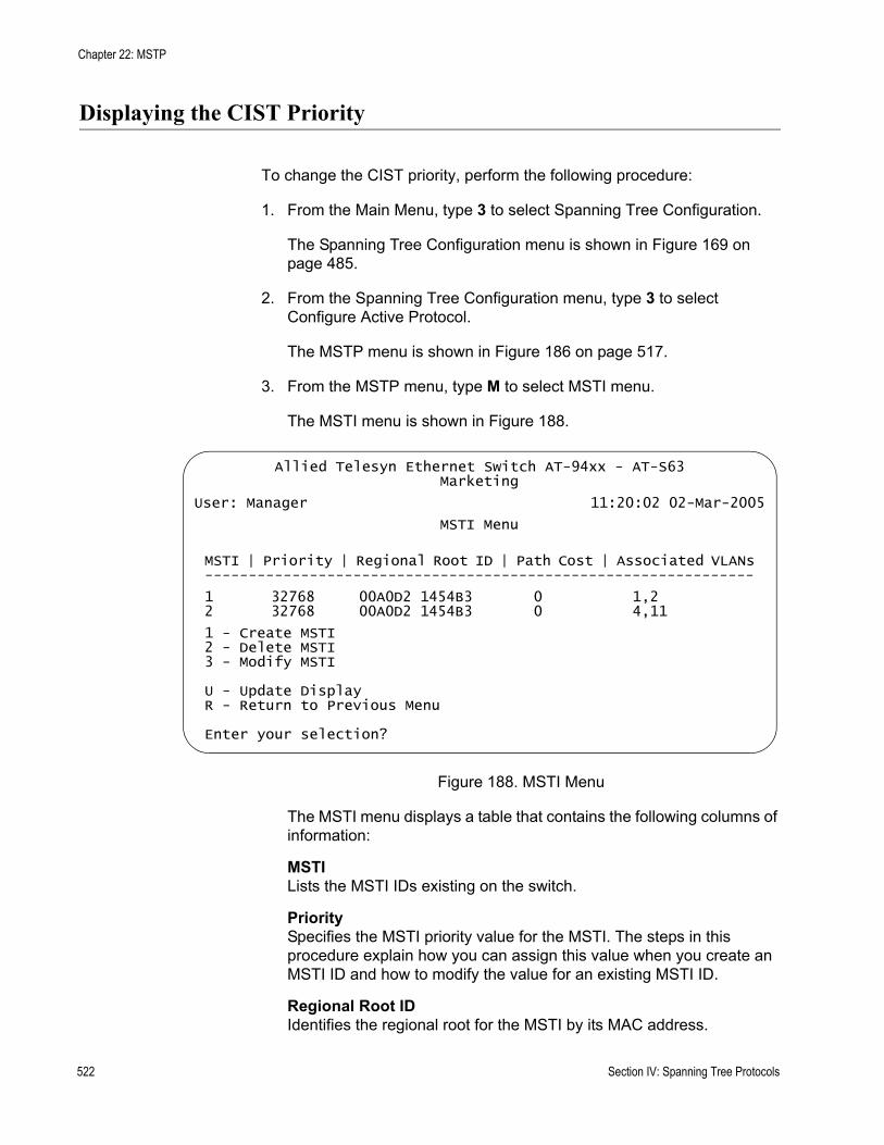
Chapter 22: MSTP
Displaying the CIST Priority
To change the CIST priority, perform the following procedure:
1. From the Main Menu, type 3 to select Spanning Tree Configuration.
The Spanning Tree Configuration menu is shown in Figure 169 on page 485.
2. From the Spanning Tree Configuration menu, type 3 to select Configure Active Protocol.
The MSTP menu is shown in Figure 186 on page 517.
3. From the MSTP menu, type M to select MSTI menu.
The MSTI menu is shown in Figure 188.
Figure 188. MSTI Menu
The MSTI menu displays a table that contains the following columns of information:
MSTILists the MSTI IDs existing on the switch.
PrioritySpecifies the MSTI priority value for the MSTI. The steps in this procedure explain how you can assign this value when you create an MSTI ID and how to modify the value for an existing MSTI ID.
Regional Root IDIdentifies the regional root for the MSTI by its MAC address.
Allied Telesyn Ethernet Switch AT-94xx - AT-S63Marketing
User: Manager 11:20:02 02-Mar-2005
MSTI Menu
MSTI | Priority | Regional Root ID | Path Cost | Associated VLANs---------------------------------------------------------------
1 32768 00A0D2 1454B3 0 1,22 32768 00A0D2 1454B3 0 4,11
1 - Create MSTI2 - Delete MSTI3 - Modify MSTI
U - Update DisplayR - Return to Previous Menu
Enter your selection?
522 Section IV: Spanning Tree Protocols

AT-S63 Management Software Menus Interface User’s Guide
Path CostSpecifies the path cost from the bridge to the regional root. If the bridge is the regional root, the value is 0.
Associated VLANsSpecifies the VIDs of the VLANs that have been associated with the MSTI ID.
The table does not include the CIST. The table is empty if no MSTI IDs have been created.
Section IV: Spanning Tree Protocols 523
Chapter 22: MSTP
Creating, Deleting, and Modifying MSTI IDs
The following sections contain procedures for working with MSTI IDs:
”Creating an MSTI ID” next“Deleting an MSTI ID” on page 525“Modifying an MSTI ID” on page 525
Creating anMSTI ID
To create an MSTI ID, perform the following procedure:
1. From the Main Menu, type 3 to select Spanning Tree Configuration.
The Spanning Tree Configuration menu is shown in Figure 169 on page 485.
2. From the Spanning Tree Configuration menu, type 3 to select Configure Active Protocol.
The MSTP menu is shown in Figure 186 on page 517.
3. From the MSTP menu, type M to select MSTI menu.
The MSTI menu is shown in Figure 188 on page 522.
4. Type 1 to select Create MSTI.
The following prompt is displayed:
Enter the MSTI ID to be created: [1 to 15] ->
5. Enter the new MSTP ID. The MSTI ID range is from 1 to 15. You can specify only one MSTI ID at a time.
The following prompt is displayed:
Success...Do you want to associate VLANs with this MSTI ID: [Yes/No] ->
6. If you want to associate VLANs to the MSTI now, type Y for yes. If you want to do it later, type N for no. (To add or remove VLANs from an existing MSTI, go to “Adding, Removing, or Modifying VLAN Associations to MSTI IDs” on page 527.)
If you respond with yes, this prompt appears:
Enter the list of VLANs:
7. Enter the VIDs of the VLANs that you want to associate with the MSTI ID. You can specify more than one VLAN at a time (for example, 4,6,11) To view VIDs, refer to “Displaying VLANs” on page 571.
524 Section IV: Spanning Tree Protocols

AT-S63 Management Software Menus Interface User’s Guide
8. After making changes, type R until you return to the Main Menu. Then type S to select Save Configuration Changes.
Deleting an MSTIID
To delete an MSTI ID, perform the following procedure:
1. From the Main Menu, type 3 to select Spanning Tree Configuration.
The Spanning Tree Configuration menu is shown in Figure 169 on page 485.
2. From the Spanning Tree Configuration menu, type 3 to select Configure Active Protocol.
The MSTP menu is shown in Figure 186 on page 517.
3. From the MSTP menu, type M to select MSTI menu.
The MSTI menu is shown in Figure 188 on page 522.
4. Type 2 to select Delete MSTI.
The following prompt is displayed:
Enter the MSTI ID to be deleted: [1 to 15] ->
5. Enter the MSTP IDs that you want to delete. The range is 1 to 15. (You cannot delete CIST, which has a value of 0.)
All VLANs associated with a deleted MSTP ID are returned to CIST.
6. After making changes, type R until you return to the Main Menu. Then type S to select Save Configuration Changes.
Modifying anMSTI ID
To change the MSTI priority value for an MSTI, perform the following procedure:
1. From the Main Menu, type 3 to select Spanning Tree Configuration.
The Spanning Tree Configuration menu is shown in Figure 169 on page 485.
2. From the Spanning Tree Configuration menu, type 3 to select Configure Active Protocol.
The MSTP menu is shown in Figure 186 on page 517.
3. From the MSTP menu, type M to select MSTI menu.
The MSTI menu is shown in Figure 188 on page 522
4. Type 3 to select Modify MSTI.
The following prompt is displayed:
Section IV: Spanning Tree Protocols 525

Chapter 22: MSTP
Enter the MSTI ID to be modified: [1 to 15] ->
5. Enter the MSTP IDs that you want to modify. The range is 1 to 15. You can specify only one MSTI ID at a time.
The following prompt is displayed:
Enter new priority [the value will be multiplied by 4096] [0 to 15] -> 8
6. Enter a new MSTI priority number for this MSTI on the bridge. This parameter is used in selecting a regional root for the MSTI. The range is 0 (zero) to 61,440 in increments of 4,096, with 0 being the highest priority. This parameter is used in selecting a regional root for the MSTI. For a list of the increments, refer to Table 9, “Bridge Priority Value Increments” on page 477.
7. After making changes, type R until you return to the Main Menu. Then type S to select Save Configuration Changes.
526 Section IV: Spanning Tree Protocols
AT-S63 Management Software Menus Interface User’s Guide
Adding, Removing, or Modifying VLAN Associations to MSTI IDs
When you create a new MSTI ID, you are given the opportunity of associating VLANs to it. But after an MSTI ID is created, you may want to add more VLANs to it, or perhaps remove VLANs. This procedure explains how to associate VLANs on the switch to an existing MSTI ID and also how to remove VLANs. Before performing this procedure, note the following:
You must create a MSTI ID before you can assign VLANs to it. To create a MSTI ID, refer to “Creating, Deleting, and Modifying MSTI IDs” on page 524.You can assign a VLAN to only one MSTI. By default, a VLAN, when created, is associated with the CIST instance, which has a MSTI ID of 0.An MSTI can contain any number of VLANs.
This section contains the following procedures:
”Adding or Removing a VLAN from an MSTI ID” next“Associating a VLAN to an MSTI ID” on page 528“Removing a VLAN from an MSTI ID” on page 529“Associating VLANs to an MSTI ID and Deleting All Associated VLANs” on page 530“Clearing VLAN to MSTI Associations” on page 531
Adding orRemoving a
VLAN from anMSTI ID
To add or remove a VLAN from an MSTI ID, perform the following procedure:
1. From the Main Menu, type 3 to select Spanning Tree Configuration.
The Spanning Tree Configuration menu is shown in Figure 169 on page 485.
2. From the Spanning Tree Configuration menu, type 3 to select Configure Active Protocol.
The MSTP menu is shown in Figure 186 on page 517.
3. From the MSTP menu, type M to select MSTI menu.
The MSTI menu is shown in Figure 188 on page 522.
4. From the MSTP menu, type V to select VLAN-MSTI Association menu.
Section IV: Spanning Tree Protocols 527
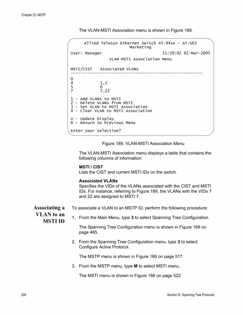
Chapter 22: MSTP
The VLAN-MSTI Association menu is shown in Figure 189.
Figure 189. VLAN-MSTI Association Menu
The VLAN-MSTI Association menu displays a table that contains the following columns of information:
MSTI / CISTLists the CIST and current MSTI IDs on the switch.
Associated VLANsSpecifies the VIDs of the VLANs associated with the CIST and MSTI IDs. For instance, referring to Figure 189, the VLANs with the VIDs 7 and 22 are assigned to MSTI 7.
Associating aVLAN to an
MSTI ID
To associate a VLAN to an MSTP ID, perform the following procedure:
1. From the Main Menu, type 3 to select Spanning Tree Configuration.
The Spanning Tree Configuration menu is shown in Figure 169 on page 485.
2. From the Spanning Tree Configuration menu, type 3 to select Configure Active Protocol.
The MSTP menu is shown in Figure 186 on page 517.
3. From the MSTP menu, type M to select MSTI menu.
The MSTI menu is shown in Figure 188 on page 522
Allied Telesyn Ethernet Switch AT-94xx - AT-S63Marketing
User: Manager 11:20:02 02-Mar-2005
VLAN-MSTI Association Menu
MSTI/CIST Associated VLANs-------------------------------------------------------
04 1,25 67 7,22
1 - Add VLANs to MSTI2 - Delete VLANs from MSTI3 - Set VLAN to MSTI Association4 - Clear VLAN to MSTI Association
U - Update DisplayR - Return to Previous Menu
Enter your selection?
528 Section IV: Spanning Tree Protocols
AT-S63 Management Software Menus Interface User’s Guide
4. From the MSTP menu, type V to select VLAN-MSTI Association menu.
The VLAN-MSTI Association menu is shown in Figure 189 on page 528.
5. From the VLAN-MSTI Association menu, type 1 to select Add VLANs to MSTI.
The following prompt is displayed:
Enter the MSTI ID <enter 0 for CIST> [0 to 15] ->
6. Enter the MSTI ID to which you want to associate a VLAN.
A prompt similar to the following is displayed:
Enter the list of VLANs:
7. Enter the VLAN ID of the virtual LAN you want to associate with the MSTI ID. You can enter more than one VLAN at a time (for example, 2,4,7). To view VIDs, refer to “Displaying VLANs” on page 571.
The MSTI ID retains any VLANs already associated with it when new VLANs are added.
8. After making changes, type R until you return to the Main Menu. Then type S to select Save Configuration Changes.
Removing aVLAN from an
MSTI ID
To remove a VLAN from an MSTP ID, perform the following procedure:
1. From the Main Menu, type 3 to select Spanning Tree Configuration.
The Spanning Tree Configuration menu is shown in Figure 169 on page 485.
2. From the Spanning Tree Configuration menu, type 3 to select Configure Active Protocol.
The MSTP menu is shown in Figure 186 on page 517.
3. From the MSTP menu, type M to select MSTI menu.
The MSTI menu is shown in Figure 188 on page 522
4. From the MSTP menu, type V to select VLAN-MSTI Association menu.
The VLAN-MSTI Association menu is shown in Figure 189 on page 528.
5. From the VLAN-MSTI Association menu, type 2 to select Delete VLANs from MSTI.
The following prompt is displayed:
Section IV: Spanning Tree Protocols 529
Chapter 22: MSTP
Enter the MSTI ID <enter 0 for CIST> [0 to 15] ->
6. Enter the MSTI ID to which you want to associate a VLAN.
A prompt similar to the following is displayed:
Enter the list of VLANs:
7. Enter the VLAN ID of the virtual LAN that you want to remove from the MSTI ID. You can enter more than one VLAN at a time (for example, 2,4,7) To view VIDs, refer to “Displaying VLANs” on page 571.
A removed VLAN is returned to CIST.
8. After making changes, type R until you return to the Main Menu. Then type S to select Save Configuration Changes.
AssociatingVLANs to anMSTI ID and
Deleting AllAssociated
VLANs
To associate VLANs to an MSTP ID while deleting all VLANs that are already associated with it, perform the following procedure:
1. From the Main Menu, type 3 to select Spanning Tree Configuration.
The Spanning Tree Configuration menu is shown in Figure 169 on page 485.
2. From the Spanning Tree Configuration menu, type 3 to select Configure Active Protocol.
The MSTP menu is shown in Figure 186 on page 517.
3. From the MSTP menu, type M to select MSTI menu.
The MSTI menu is shown in Figure 188 on page 522
4. From the MSTP menu, type V to select VLAN-MSTI Association menu.
The VLAN-MSTI Association menu is shown in Figure 189 on page 528.
5. From the VLAN-MSTI Association menu, type 1 to select Add VLANs to MSTI.
The following prompt is displayed:
Enter the MSTI ID <enter 0 for CIST> [0 to 15] ->
6. Enter the MSTI ID to which you want to associate a VLAN.
7. A prompt similar to the following is displayed:
Enter the list of VLANs:
530 Section IV: Spanning Tree Protocols
AT-S63 Management Software Menus Interface User’s Guide
8. Enter the VLAN ID of the virtual LAN that you want to associate with the MSTI ID. You can enter more than one VLAN at a time (for example, 2,4,7) (To view VIDs, refer to “Displaying VLANs” on page 571.)
The VLANs already associated with the MSTI ID are removed when the new VLANs are added. The removed VLANs are returned to CIST.
9. After making changes, type R until you return to the Main Menu. Then type S to select Save Configuration Changes.
Clearing VLANto MSTI
Associations
To clear VLAN to MSTI associations, perform the following procedure:
1. From the Main Menu, type 3 to select Spanning Tree Configuration.
The Spanning Tree Configuration menu is shown in Figure 169 on page 485.
2. From the Spanning Tree Configuration menu, type 3 to select Configure Active Protocol.
The MSTP menu is shown in Figure 186 on page 517.
3. From the MSTP menu, type M to select MSTI menu.
The MSTI menu is shown in Figure 188 on page 522
4. From the MSTP menu, type V to select VLAN-MSTI Association menu.
The VLAN-MSTI Association menu is shown in Figure 189 on page 528.
5. From the VLAN-MSTI Association menu, type 4 to select Clear VLAN to MSTI Association.
The following prompt is displayed:
Enter the MSTI ID: [1 to 15] ->
6. Type the MSTI ID number and press Return.
Section IV: Spanning Tree Protocols 531
Chapter 22: MSTP
Configuring MSTP Port Settings
As explained in “Ports in Multiple MSTIs” on page 507, MSTP port settings are divided into two groups. The parameters in the first group are set just once on a port, regardless of the number of MSTIs in which a port is a member. These settings are:
External path costPoint-to-point designationEdge port designation
The procedure for setting these parameters is in “Configuring Generic MSTP Port Settings” on page 532.
The second group of port parameters can be set independently for each MSTI in which the port is a member. These parameters are:
Internal path costPriority
To set these parameters, refer to “Configuring MSTI-specific Port Parameters” on page 534.
ConfiguringGeneric MSTP
Port Settings
To configure the external path cost of a port or to designate whether the port is an edge or point-to-point port, perform the following procedure:
1. From the Main Menu, type 3 to select Spanning Tree Configuration.
The Spanning Tree Configuration menu is shown in Figure 169 on page 485.
2. From the Spanning Tree Configuration menu, type 3 to select Configure Active Protocol.
The MSTP menu is shown in Figure 186 on page 517.
3. From the MSTP menu, type P to select MSTP Port Parameters.
532 Section IV: Spanning Tree Protocols
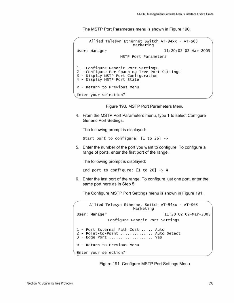
AT-S63 Management Software Menus Interface User’s Guide
The MSTP Port Parameters menu is shown in Figure 190.
Figure 190. MSTP Port Parameters Menu
4. From the MSTP Port Parameters menu, type 1 to select Configure Generic Port Settings.
The following prompt is displayed:
Start port to configure: [1 to 26] ->
5. Enter the number of the port you want to configure. To configure a range of ports, enter the first port of the range.
The following prompt is displayed:
End port to configure: [1 to 26] -> 4
6. Enter the last port of the range. To configure just one port, enter the same port here as in Step 5.
The Configure MSTP Port Settings menu is shown in Figure 191.
Figure 191. Configure MSTP Port Settings Menu
Allied Telesyn Ethernet Switch AT-94xx - AT-S63Marketing
User: Manager 11:20:02 02-Mar-2005
MSTP Port Parameters
1 - Configure Generic Port Settings2 - Configure Per Spanning Tree Port Settings3 - Display MSTP Port Configuration4 - Display MSTP Port State
R - Return to Previous Menu
Enter your selection?
Allied Telesyn Ethernet Switch AT-94xx - AT-S63Marketing
User: Manager 11:20:02 02-Mar-2005
Configure Generic Port Settings
1 - Port External Path Cost ..... Auto2 - Point-to-Point .............. Auto Detect3 - Edge Port ................... Yes
R - Return to Previous Menu
Enter your selection?
Section IV: Spanning Tree Protocols 533
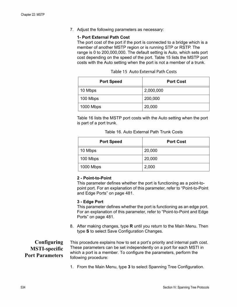
Chapter 22: MSTP
7. Adjust the following parameters as necessary:
1- Port External Path CostThe port cost of the port if the port is connected to a bridge which is a member of another MSTP region or is running STP or RSTP. The range is 0 to 200,000,000. The default setting is Auto, which sets port cost depending on the speed of the port. Table 15 lists the MSTP port costs with the Auto setting when the port is not a member of a trunk.
Table 16 lists the MSTP port costs with the Auto setting when the port is part of a port trunk.
2 - Point-to-PointThis parameter defines whether the port is functioning as a point-to-point port. For an explanation of this parameter, refer to “Point-to-Point and Edge Ports” on page 481.
3 - Edge PortThis parameter defines whether the port is functioning as an edge port. For an explanation of this parameter, refer to “Point-to-Point and Edge Ports” on page 481.
8. After making changes, type R until you return to the Main Menu. Then type S to select Save Configuration Changes.
ConfiguringMSTI-specific
Port Parameters
This procedure explains how to set a port’s priority and internal path cost. These parameters can be set independently on a port for each MSTI in which a port is a member. To configure the parameters, perform the following procedure:
1. From the Main Menu, type 3 to select Spanning Tree Configuration.
Table 15 Auto External Path Costs
Port Speed Port Cost
10 Mbps 2,000,000
100 Mbps 200,000
1000 Mbps 20,000
Table 16. Auto External Path Trunk Costs
Port Speed Port Cost
10 Mbps 20,000
100 Mbps 20,000
1000 Mbps 2,000
534 Section IV: Spanning Tree Protocols

AT-S63 Management Software Menus Interface User’s Guide
The Spanning Tree Configuration menu is shown in Figure 169 on page 485.
2. From the Spanning Tree Configuration menu, type 3 to select Configure Active Protocol.
The MSTP menu is shown in Figure 186 on page 517.
3. From the MSTP menu, type P to select MSTP Port Parameters.
The MSTP Port Parameters menu is shown in Figure 190 on page 533.
4. Type 2 to select Configure Per Spanning Tree Port Settings.
The following prompt is displayed:
Enter Spanning Tree (CIST/MSTI) List :
5. Enter the ID number of the CIST or MSTI where the VLAN containing the port whose settings you want to configure has been assigned. You can specify more than one ID number.
The following prompt is displayed:
Start port to configure: [1 to 26] -> 1
6. Enter the number of the port you want to configure. To configure a range of ports, enter the first port of the range.
The following prompt is displayed:
End port to configure: [1 to 26] -> 1
7. Enter the last port of the range. To configure just one port, enter the same port here as in Step 6.
Section IV: Spanning Tree Protocols 535

Chapter 22: MSTP
Configure Per Spanning Tree Port Settings Menu is shown in Figure 192.
Figure 192. Configure Per Spanning Tree Port Settings Menu
The Spanning Tree List displays the ID numbers of the MSTIs you specified.
8. Adjust the following parameters as necessary:
1 - Port PriorityThis parameter is used as a tie breaker when two or more ports are determined to have equal costs to the regional root bridge. The range is 0 to 240 in increments of 16. The default value is 8 (priority value 128). For a list of the increments, refer to Table 14, “Port Priority Value Increments” on page 479.
2- Port Internal Path CostThe port cost of the port if the port is connected to a bridge which is part of the same MSTP region. The range is 0 to 200,000,000. The default setting is 0, Auto Update, which sets port cost depending on the speed of the port. Default values are 2,000,000 for 10 Mbps ports, 200,000 for a 100 Mbps ports, and 20,000 for one gigabit ports.
Table 17 lists the RSTP port costs with Auto-Detect.
Allied Telesyn Ethernet Switch AT-94xx - AT-S63Marketing
User: Manager 11:20:02 02-Mar-2005
Configure Per Spanning Tree Port Settings
Spanning Tree List: 4Configuring Ports: 7-7
1 - Port Priority ............... 1282 - Port Internal Path Cost ..... Auto Update
R - Return to Previous Menu
Enter your selection?
Table 17. RSTP Auto-Detect Port Costs
Port Speed Port Cost
10 Mbps 2,000,000
100 Mbps 200,000
1000 Mbps 20,000
536 Section IV: Spanning Tree Protocols
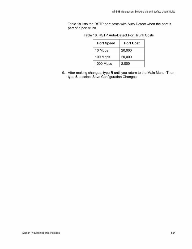
AT-S63 Management Software Menus Interface User’s Guide
Table 18 lists the RSTP port costs with Auto-Detect when the port is part of a port trunk.
9. After making changes, type R until you return to the Main Menu. Then type S to select Save Configuration Changes.
Table 18. RSTP Auto-Detect Port Trunk Costs
Port Speed Port Cost
10 Mbps 20,000
100 Mbps 20,000
1000 Mbps 2,000
Section IV: Spanning Tree Protocols 537
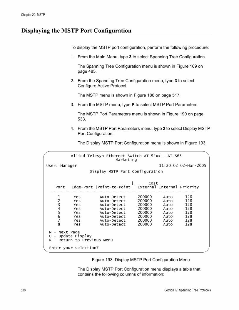
Chapter 22: MSTP
Displaying the MSTP Port Configuration
To display the MSTP port configuration, perform the following procedure:
1. From the Main Menu, type 3 to select Spanning Tree Configuration.
The Spanning Tree Configuration menu is shown in Figure 169 on page 485.
2. From the Spanning Tree Configuration menu, type 3 to select Configure Active Protocol.
The MSTP menu is shown in Figure 186 on page 517.
3. From the MSTP menu, type P to select MSTP Port Parameters.
The MSTP Port Parameters menu is shown in Figure 190 on page 533.
4. From the MSTP Port Parameters menu, type 2 to select Display MSTP Port Configuration.
The Display MSTP Port Configuration menu is shown in Figure 193.
Figure 193. Display MSTP Port Configuration Menu
The Display MSTP Port Configuration menu displays a table that contains the following columns of information:
Allied Telesyn Ethernet Switch AT-94xx - AT-S63Marketing
User: Manager 11:20:02 02-Mar-2005
Display MSTP Port Configuration
| Cost |Port | Edge-Port |Point-to-Point | External Internal|Priority
--------------------------------------------------------------
1 Yes Auto-Detect 200000 Auto 128 2 Yes Auto-Detect 200000 Auto 128 3 Yes Auto-Detect 200000 Auto 128 4 Yes Auto-Detect 200000 Auto 128 5 Yes Auto-Detect 200000 Auto 128 6 Yes Auto-Detect 200000 Auto 128 7 Yes Auto-Detect 200000 Auto 128 8 Yes Auto-Detect 200000 Auto 128
N - Next PageU - Update DisplayR - Return to Previous Menu
Enter your selection?
538 Section IV: Spanning Tree Protocols
AT-S63 Management Software Menus Interface User’s Guide
PortThe port number.
Edge-PortWhether or not the port is functioning as an edge port. The possible settings are Yes and No.
Point-to-PointWhether or not the port is functioning as a point-to-point port. The possible settings are Yes, No, and Auto-Detect.
External or Internal Port CostExternal Port CostThe port cost of the port if the port is connected to a bridge which is a member of another MSTP region or is running STP or RSTP.
Internal Port CostThe port cost of the port if the port is connected to a bridge which is part of the same MSTP region. The possible settings are:
Auto-detect - Port cost is automatically set depending on the speed of the port. Default values are 2,000,000 for 10 Mbps ports, 200,000 for a 100 Mbps ports, and 20,000 for one gigabit ports.
PriorityThis parameter is used as a tie breaker when two or more ports are determined to have equal costs to the regional root bridge.
Section IV: Spanning Tree Protocols 539
Chapter 22: MSTP
Displaying the MSTP Port State
To display the MSTP port state, perform the following procedure:
1. From the Main Menu, type 3 to select Spanning Tree Configuration.
The Spanning Tree Configuration menu is shown in Figure 169 on page 485.
2. From the Spanning Tree Configuration menu, type 3 to select Configure Active Protocol.
The MSTP menu is shown in Figure 186 on page 517.
3. From the MSTP menu, type P to select MSTP Port Parameters.
The MSTP Port Parameters menu is shown in Figure 190 on page 533.
4. From the MSTP Port Parameters menu, type 3 to select Display MSTP Port State.
The following prompt is displayed:
Enter Spanning Tree (CIST/MSTI) ID to display port state: [0 to 15} ->
5. Enter an MSTI ID.
540 Section IV: Spanning Tree Protocols
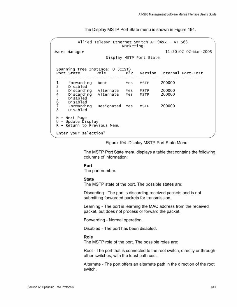
AT-S63 Management Software Menus Interface User’s Guide
The Display MSTP Port State menu is shown in Figure 194.
Figure 194. Display MSTP Port State Menu
The MSTP Port State menu displays a table that contains the following columns of information:
PortThe port number.
StateThe MSTP state of the port. The possible states are:
Discarding - The port is discarding received packets and is not submitting forwarded packets for transmission.
Learning - The port is learning the MAC address from the received packet, but does not process or forward the packet.
Forwarding - Normal operation.
Disabled - The port has been disabled.
RoleThe MSTP role of the port. The possible roles are:
Root - The port that is connected to the root switch, directly or through other switches, with the least path cost.
Alternate - The port offers an alternate path in the direction of the root switch.
Allied Telesyn Ethernet Switch AT-94xx - AT-S63Marketing
User: Manager 11:20:02 02-Mar-2005
Display MSTP Port State
Spanning Tree Instance: 0 (CIST)Port State Role P2P Version Internal Port-Cost--------------------------------------------------------------
1 Forwarding Root Yes MSTP 2000002 Disabled3 Discarding Alternate Yes MSTP 2000004 Discarding Alternate Yes MSTP 2000005 Disabled6 Disabled7 Forwarding Designated Yes MSTP 2000008 Disabled
N - Next PageU - Update DisplayR - Return to Previous Menu
Enter your selection?
Section IV: Spanning Tree Protocols 541
Chapter 22: MSTP
Backup - The port on a designated switch that provides a backup for the path provided by the designated port.
Designated - The port on the designated switch for a LAN that has the least cost path to the root switch. This port connects the LAN to the root switch.
Master - Similar to the root port. When the port is a boundary port, the MSTI port roles follow the CIST port roles. The MSTI port role is called “master” when the CIST role is “root.”
P2PWhether or not the port is functioning as a point-to-point port. The possible settings are Yes, No, and Auto-Detect.
VersionWhether the port is operating in MSTP mode or STP-compatible mode.
Internal Port-CostThe port cost when the port is connected to a bridge in the same MSTP region.
542 Section IV: Spanning Tree Protocols
AT-S63 Management Software Menus Interface User’s Guide
Resetting MSTP to the Defaults
To reset MSTP to the defaults, perform the following procedure:
1. From the Main Menu, type 3 to select Spanning Tree Configuration.
The Spanning Tree Configuration menu is shown in Figure 169 on page 485.
2. From the Spanning Tree Configuration menu, type 3 to select Configure Active Protocol.
The MSTP menu is shown in Figure 186 on page 517.
3. From the MSTP menu, type D to select Reset MSTP to Defaults.
The following message is displayed:
Do you want to reset MSTP configuration to default? [Yes/No] ->
4. Enter Y for Yes or N for No and press Return.
The MSTP configuration is reset to the defaults.
Section IV: Spanning Tree Protocols 543

Chapter 22: MSTP
544 Section IV: Spanning Tree Protocols
Section V
Virtual LANs
The chapters in this section provide information and procedures for basic switch setup using the AT-S63 management software. The chapters include:
Chapter 23, “Port-based and Tagged VLANs” on page 547Chapter 24, “GARP VLAN Registration Protocol” on page 583Chapter 25, “Multiple VLANs” on page 611Chapter 26, “Protected Ports VLANs” on page 619
Section V: VLANs 545

546 Section V: VLANs

Chapter 23
Port-based and Tagged VLANs
This chapter contains basic information about virtual LANs (VLANs) and procedures for creating, modifying, and deleting VLANs from a local or Telnet management session.
This chapter contains the following sections:
“VLAN Overview” on page 548“Port-based VLAN Overview” on page 550“Tagged VLAN Overview” on page 556“Creating a New Port-based or Tagged VLAN” on page 561“Example of Creating a Port-based VLAN” on page 565“Example of Creating a Tagged VLAN” on page 566“Modifying a VLAN” on page 567“Displaying VLANs” on page 571“Deleting a VLAN” on page 573“Resetting to the Default VLAN” on page 576“Displaying PVIDs” on page 578“Enabling or Disabling Ingress Filtering” on page 579“Specifying a Management VLAN” on page 581
Section V: VLANs 547
Chapter 23: Port-based and Tagged VLANs
VLAN Overview
A VLAN is a group of ports on an Ethernet switch that form a logical Ethernet segment. The ports of a VLAN form an independent traffic domain where the traffic generated by the nodes of a VLAN remains within the VLAN.
With VLANs, you can segment your network through the switch’s AT-S63 management software and so be able to group nodes with related functions into their own separate, logical LAN segments. These VLAN groupings can be based on similar data needs or security requirements. For example, you could create separate VLANs for the different departments in your company, such as one for Sales and another for Accounting.
VLANs offer several important benefits:
Improved network performance
Network performance often suffers as networks grow in size and as data traffic increases. The more nodes on each LAN segment vying for bandwidth, the greater the likelihood overall network performance decreases.
VLANs improve network perform because VLAN traffic stays within the VLAN. The nodes of a VLAN receive traffic only from nodes of the same VLAN. This reduces the need for nodes to handle traffic not destined for them. It also frees up bandwidth within all the logical workgroups.
In addition, because each VLAN constitutes a separate broadcast domain, broadcast traffic remains within the VLAN. This too can improve overall network performance.
Increased security
Because data traffic generated by a node in a VLAN is restricted only to the other nodes of the same VLAN, you can use VLANs to control the flow of packets in your network and prevent packets from flowing to unauthorized end nodes.
Simplified network management
VLANs can also simplify network management. Before the advent of VLANs, physical changes to the network often had to been made at the switches in the wiring closets. For example, if an employee changed departments, changing the employee’s LAN segment assignment might require a change to the wiring at the switches.
But with VLANS, you can change the LAN segment assignment of an end node connected to the switch through the switch’s AT-S63
548 Section V: VLANs

AT-S63 Management Software Menus Interface User’s Guide
management software. You can change the VLAN memberships through the management software without moving the workstations physically, or changing group memberships by moving cables from one switch port to another.
In addition, a virtual LAN can span more than one switch. This means that the end nodes of a VLAN do not need to be connected to the same switch and so are not restricted to being in the same physical location.
NoteWhen a transceiver is inserted into an uplink slot and a link is established, that slot becomes a primary uplink port and the corresponding backup port, 23R or 24R, automatically transitions to redundant uplink status. Any VLAN settings remain intact when the backup port makes the transition to a redundant uplink state.
The AT-9400 Series switch supports the following types of VLANs you can create yourself:
Port-based VLANsTagged VLANs
These VLANs are described in the following sections.
Section V: VLANs 549
Chapter 23: Port-based and Tagged VLANs
Port-based VLAN Overview
As explained in “VLAN Overview” on page 548, a VLAN consists of a group of ports on one or more Ethernet switches that form an independent traffic domain. Traffic generated by the end nodes of a VLAN remains within the VLAN and does not cross over to the end nodes of other VLANs unless there is an interconnection device, such as a router or Layer 3 switch.
A port-based VLAN is a group of ports on a Gigabit Ethernet Switch that form a logical Ethernet segment. Each port of a port-based VLAN can belong to only one VLAN at a time.
A port-based VLAN can have as many or as few ports as needed. The VLAN can consist of all the ports on an Ethernet switch, or just a few ports. A port-based VLAN also can span switches and consist of ports from multiple Ethernet switches.
NoteThe AT-9400 Series switch is preconfigured with one port-based VLAN. All ports on the switch are members of this VLAN, called the Default_VLAN.
The parts that make up a port-based VLAN are:
VLAN nameVLAN IdentifierUntagged portsPort VLAN Identifier
VLAN Name To create a port-based VLAN, you must give it a name. The name should reflect the function of the network devices that are be members of the VLAN. Examples include Sales, Production, and Engineering.
VLAN Identifier Each VLAN in a network must have a unique number assigned to it. This number is called the VLAN identifier (VID). This number uniquely identifies a VLAN in the switch and the network.
If a VLAN consists only of ports located on one physical switch in your network, you assign it a VID different from all other VLANs in your network.
If a VLAN spans multiple switches, then the VID for the VLAN on the different switches should be the same. The switches are then able to recognize and forward frames belonging to the same VLAN even though the VLAN spans multiple switches.
550 Section V: VLANs
AT-S63 Management Software Menus Interface User’s Guide
For example, if you had a port-based VLAN titled Marketing that spanned three AT-9400 Series switches, you would assign the Marketing VLAN on each switch the same VID.
You can assign this number manually or allow the AT-S63 management software to do it automatically. If you allow the management software to do it automatically, it selects the next available VID. This is acceptable when you are creating a new, unique VLAN.
If you are creating a VLAN on a switch that will be part of a larger VLAN that spans several switch, then you will need to assign the number yourself so that the VLAN has the same VID on all switches.
Untagged Ports You need to specify which ports on the switch are to be members of a port-based VLAN. Ports in a port-based VLAN are referred to as untagged ports and the frames received on the ports as untagged frames. The names derive from the fact that the frames received on a port will not contain any information that indicates VLAN membership, and that VLAN membership will be determined solely by the port’s PVID. (There is another type of VLAN where VLAN membership is determined by information within the frames themselves, rather than by a port’s PVID. This type of VLAN is explained in “Tagged VLAN Overview” on page 556.)
A port on a switch can be an untagged member of only one port-based VLAN at a time. An untagged port cannot be assigned to two port-based VLANs simultaneously.
Port VLANIdentifier
Each port in a port-based VLAN must have a port VLAN identifier (PVID). The switch associates a frame to a port-based VLAN by the PVID assigned to the port on which the frame is received, and forwards the frame only to those ports with the same PVID. Consequently, all ports of a port-based VLAN must have the same PVID. Additionally, the PVID of the ports in a VLAN must match the VLAN’s VID.
For example, if you were creating a port-based VLAN on a switch and you had assigned the VLAN the VID 5, the PVID for each port in the VLAN would need to be assigned the value 5.
Some switches and switch management programs require that you assign the PVID value for each port manually. However, the AT-S63 management software performs this task automatically. The software automatically assigns a PVID to a port, making it identical to the VID of the VLAN to which the port is a member, when you assign the port as an untagged member to a VLAN.
General Rules forCreating a Port-
based VLAN
Below is a summary of the general rules to observe when creating a port-based VLAN.
Section V: VLANs 551
Chapter 23: Port-based and Tagged VLANs
Each port-based VLAN must be assigned a unique VID. If a particular VLAN spans multiples switches, each part of the VLAN on the different switches should be assigned the same VID.A port can be an untagged member of only one port-based VLAN at a time.Each port must be assigned a PVID. This value must be the same for all ports in a port-based VLAN and it must match the VLAN’s VID. This value is automatically assigned by the AT-S63 management software.A port-based VLAN that spans multiple switches requires a port on each switch where the VLAN is located to function as an interconnection between the switches where the various parts of the VLAN reside.If there are end nodes in different VLANs that need to communicate with each other, a router or Layer 3 switch is required to interconnect the VLANs.An AT-9400 Series switch can support up to 4094 port-based VLANs.
Drawbacks ofPort-based
VLANs
There are several drawbacks to port-based VLANs:
It is not easy to share network resources, such as servers and printers, across multiple VLANs. A router or Layer 3 switch must be added to the network to provide a means for interconnecting the port-based VLANs. The introduction of a router into your network could create security issues from unauthorized access to your network.A VLAN that spans several switches requires a port on each switch for the interconnection of the various parts of the VLAN. For example, a VLAN that spans three switches would require one port on each switch to interconnect the various sections of the VLAN. In network configurations where there are many individual VLANs that span switches, many ports could end up being used ineffectively just to interconnect the various VLANs.
Port-basedExample 1
Figure 195 illustrates an example of one AT-9424T/SP Gigabit Ethernet Switch with three port-based VLANs. (For purposes of the following
552 Section V: VLANs
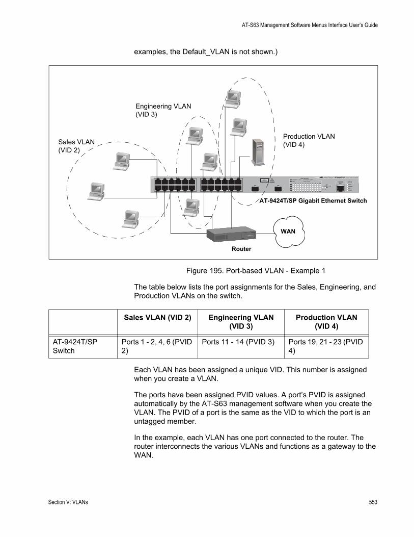
AT-S63 Management Software Menus Interface User’s Guide
examples, the Default_VLAN is not shown.)
Figure 195. Port-based VLAN - Example 1
The table below lists the port assignments for the Sales, Engineering, and Production VLANs on the switch.
Each VLAN has been assigned a unique VID. This number is assigned when you create a VLAN.
The ports have been assigned PVID values. A port’s PVID is assigned automatically by the AT-S63 management software when you create the VLAN. The PVID of a port is the same as the VID to which the port is an untagged member.
In the example, each VLAN has one port connected to the router. The router interconnects the various VLANs and functions as a gateway to the WAN.
Router
AT-9424T/SP Gigabit Ethernet Switch
WAN
FAULT
RPS
MASTER
POWER
CLASS 1LASER PRODUCT
STATUSTERMINALPORT
1 3 5 7 9 11
2 4 6 8 10 12
13 15 17 19 21 23R
14 16 18 20 22 24R
AT-9424T/SP Gigabit Ethernet Switch
1 3 5 7 9 11 13 15 17 19 21 23R
2 4 6 8 10 12 14 16 18 20 22 24R
23 24
L/A
D/C
D/C
L/A
D/C
L/A 1000 LINK / ACT
HDX / COLFDX
10/100 LINK / ACTPORT ACTIVITY
L/A
1000 LINK / ACTSFPSFP
24
SFP
23
Sales VLAN(VID 2)
Engineering VLAN(VID 3)
Production VLAN(VID 4)
Sales VLAN (VID 2) Engineering VLAN (VID 3)
Production VLAN (VID 4)
AT-9424T/SP Switch
Ports 1 - 2, 4, 6 (PVID 2)
Ports 11 - 14 (PVID 3) Ports 19, 21 - 23 (PVID 4)
Section V: VLANs 553
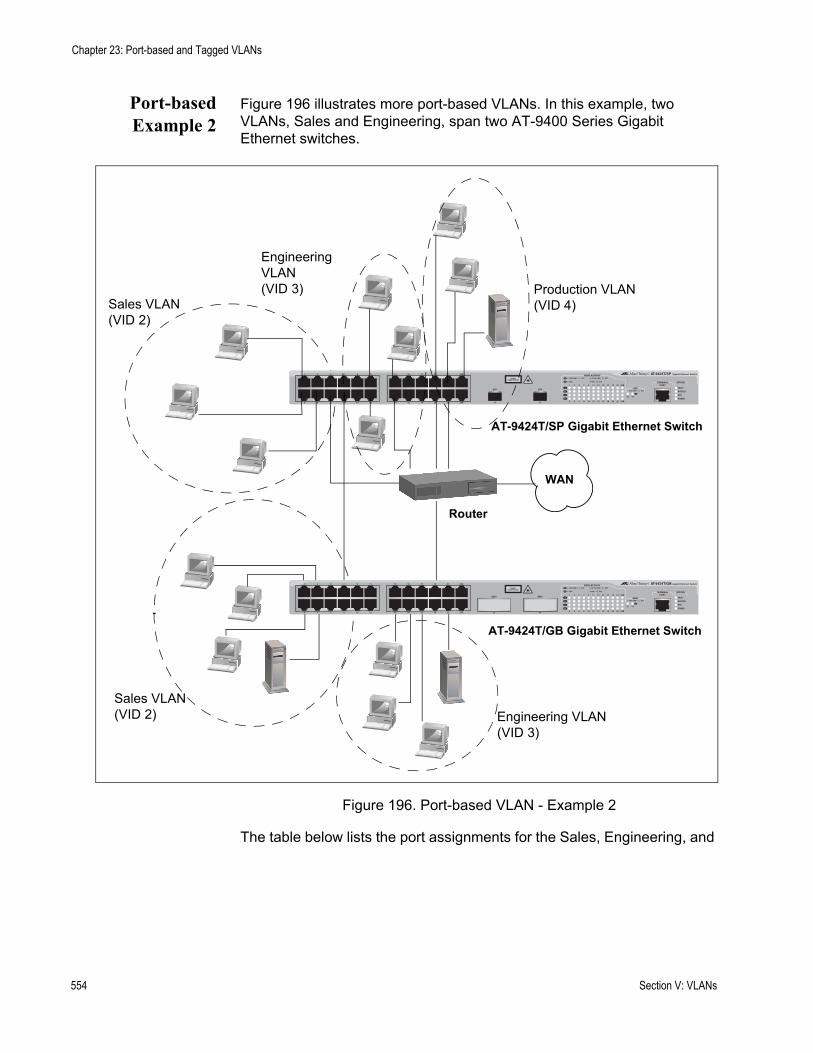
Chapter 23: Port-based and Tagged VLANs
Port-basedExample 2
Figure 196 illustrates more port-based VLANs. In this example, two VLANs, Sales and Engineering, span two AT-9400 Series Gigabit Ethernet switches.
Figure 196. Port-based VLAN - Example 2
The table below lists the port assignments for the Sales, Engineering, and
Router
AT-9424T/SP Gigabit Ethernet Switch
WAN
FAULT
RPS
MASTER
POWER
CLASS 1LASER PRODUCT
STATUSTERMINALPORT
1 3 5 7 9 11
2 4 6 8 10 12
13 15 17 19 21 23R
14 16 18 20 22 24R
AT-9424T/SP Gigabit Ethernet Switch
1 3 5 7 9 11 13 15 17 19 21 23R
2 4 6 8 10 12 14 16 18 20 22 24R
23 24
L/A
D/C
D/C
L/A
D/C
L/A 1000 LINK / ACT
HDX / COLFDX
10/100 LINK / ACTPORT ACTIVITY
L/A
1000 LINK / ACTSFPSFP
24
SFP
23
Sales VLAN(VID 2)
Engineering VLAN(VID 3) Production VLAN
(VID 4)
Sales VLAN(VID 2) Engineering VLAN
(VID 3)
AT-9424T/GB Gigabit Ethernet Switch
FAULT
RPS
MASTER
POWER
GBIC
23
GBIC
24
CLASS 1LASER PRODUCT
STATUSTERMINALPORT
1 3 5 7 9 11
2 4 6 8 10 12
13 15 17 19 21 23R
14 16 18 20 22 24R
AT-9424T/GB Gigabit Ethernet Switch
1 3 5 7 9 11 13 15 17 19 21 23R
2 4 6 8 10 12 14 16 18 20 22 24R
23 24
L/A
D/C
D/C
L/A
D/C
L/A 1000 LINK / ACT
HDX / COLFDX
10/100 LINK / ACTPORT ACTIVITY
L/A
1000 LINK / ACTGBIC
554 Section V: VLANs
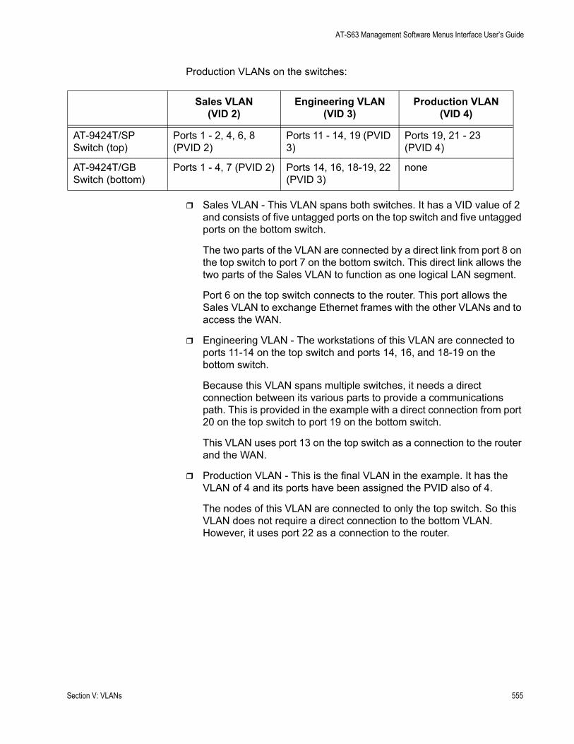
AT-S63 Management Software Menus Interface User’s Guide
Production VLANs on the switches:
Sales VLAN - This VLAN spans both switches. It has a VID value of 2 and consists of five untagged ports on the top switch and five untagged ports on the bottom switch.
The two parts of the VLAN are connected by a direct link from port 8 on the top switch to port 7 on the bottom switch. This direct link allows the two parts of the Sales VLAN to function as one logical LAN segment.
Port 6 on the top switch connects to the router. This port allows the Sales VLAN to exchange Ethernet frames with the other VLANs and to access the WAN.
Engineering VLAN - The workstations of this VLAN are connected to ports 11-14 on the top switch and ports 14, 16, and 18-19 on the bottom switch.
Because this VLAN spans multiple switches, it needs a direct connection between its various parts to provide a communications path. This is provided in the example with a direct connection from port 20 on the top switch to port 19 on the bottom switch.
This VLAN uses port 13 on the top switch as a connection to the router and the WAN.
Production VLAN - This is the final VLAN in the example. It has the VLAN of 4 and its ports have been assigned the PVID also of 4.
The nodes of this VLAN are connected to only the top switch. So this VLAN does not require a direct connection to the bottom VLAN. However, it uses port 22 as a connection to the router.
Sales VLAN (VID 2)
Engineering VLAN (VID 3)
Production VLAN (VID 4)
AT-9424T/SP Switch (top)
Ports 1 - 2, 4, 6, 8 (PVID 2)
Ports 11 - 14, 19 (PVID 3)
Ports 19, 21 - 23 (PVID 4)
AT-9424T/GB Switch (bottom)
Ports 1 - 4, 7 (PVID 2) Ports 14, 16, 18-19, 22 (PVID 3)
none
Section V: VLANs 555
Chapter 23: Port-based and Tagged VLANs
Tagged VLAN Overview
The second type of VLAN supported by the AT-S63 management software is the tagged VLAN. VLAN membership in a tagged VLAN is determined by information within the frames that are received on a port. This differs from a port-based VLAN, where the PVIDs assigned to the ports determine VLAN membership.
The VLAN information within an Ethernet frame is referred to as a tag or tagged header. A tag, which follows the source and destination addresses in a frame, contains the VID of the VLAN to which the frame belongs (IEEE 802.3ac standard). As explained earlier in this chapter in “VLAN Identifier” on page 550, this number uniquely identifies each VLAN in a network.
When a switch receives a frame with a VLAN tag, referred to as a tagged frame, the switch forwards the frame only to those ports that share the same VID.
A port to receive or transmit tagged frames is referred to as a tagged port. Any network device connected to a tagged port must be IEEE 802.1Q-compliant. This is the standard that outlines the requirements and standards for tagging. The device must be able to process the tagged information on received frames and add tagged information to transmitted frames.
The benefit of a tagged VLAN is that the tagged ports can belong to more than one VLAN at one time. This can greatly simplify the task of adding shared devices to the network. For example, a server can be configured to accept and return packets from many different VLANs simultaneously.
Tagged VLANs are also useful where multiple VLANs span across switches. You can use one port per switch to connect all VLANs on the switch to another switch.
The IEEE 802.1Q standard describes how this tagging information is used to forward the traffic throughout the switch. The handling of frames tagged with VIDs coming into a port is straightforward. If the incoming frame’s VID tag matches one of the VIDs of a VLAN of which the port is a tagged member, the frame is accepted and forwarded to the appropriate ports. If the frame’s VID does not match any of the VLANs that the port is a member of, the frame is discarded.
The parts of a tagged VLAN are much the same as those for a port-based VLAN. They are:
VLAN NameVLAN Identifier
556 Section V: VLANs
AT-S63 Management Software Menus Interface User’s Guide
Tagged and Untagged PortsPort VLAN Identifier
NoteFor explanations of VLAN name and VLAN identifier, refer back to “VLAN Name” on page 550 and “VLAN Identifier” on page 550.
Tagged andUntagged Ports
You need to specify which ports will be members of the VLAN. In the case of a tagged VLAN, it is usually a combination of both untagged ports and tagged ports. You specify which ports are tagged and which untagged when you create the VLAN.
An untagged port, whether a member of a port-based VLAN or a tagged VLAN, can be in only one VLAN at a time. However, a tagged port can be a member of more than one VLAN. A port can also be an untagged member of one VLAN and a tagged member of different VLANs simultaneously.
Port VLANIdentifier
As explained earlier in the discussion on port-based VLANs, the AT-S63 management software automatically assigns a PVID to each port when a port is made a member of a VLAN. The PVID is always identical to the VLAN’s VID, and that in a port-based VLAN packets are forwarded based on the PVID.
Because a tagged port determines VLAN membership by examining the tagged header within the frames that it receives, you could conclude that there is no need for a PVID. However, the PVID is used if a tagged port receives an untagged frame—a frame without any tagged information. The port forwards the frame based on the port’s PVID. This is only in cases where an untagged frame arrives on a tagged port. Otherwise, the PVID of a port is ignored on a tagged port.
Section V: VLANs 557

Chapter 23: Port-based and Tagged VLANs
General Rules forCreating a
Tagged VLAN
Below is a summary of the rules to observe when you create a tagged VLAN.
Each tagged VLAN must be assigned a unique VID. If a particular VLAN spans multiple switches, each part of the VLAN on the different switches must be assigned the same VID.A tagged port can be a member of multiple VLANs.An untagged port can be an untagged member of only one VLAN at a time.An AT-9400 Series switch can support up to 4094 tagged VLANS.
558 Section V: VLANs
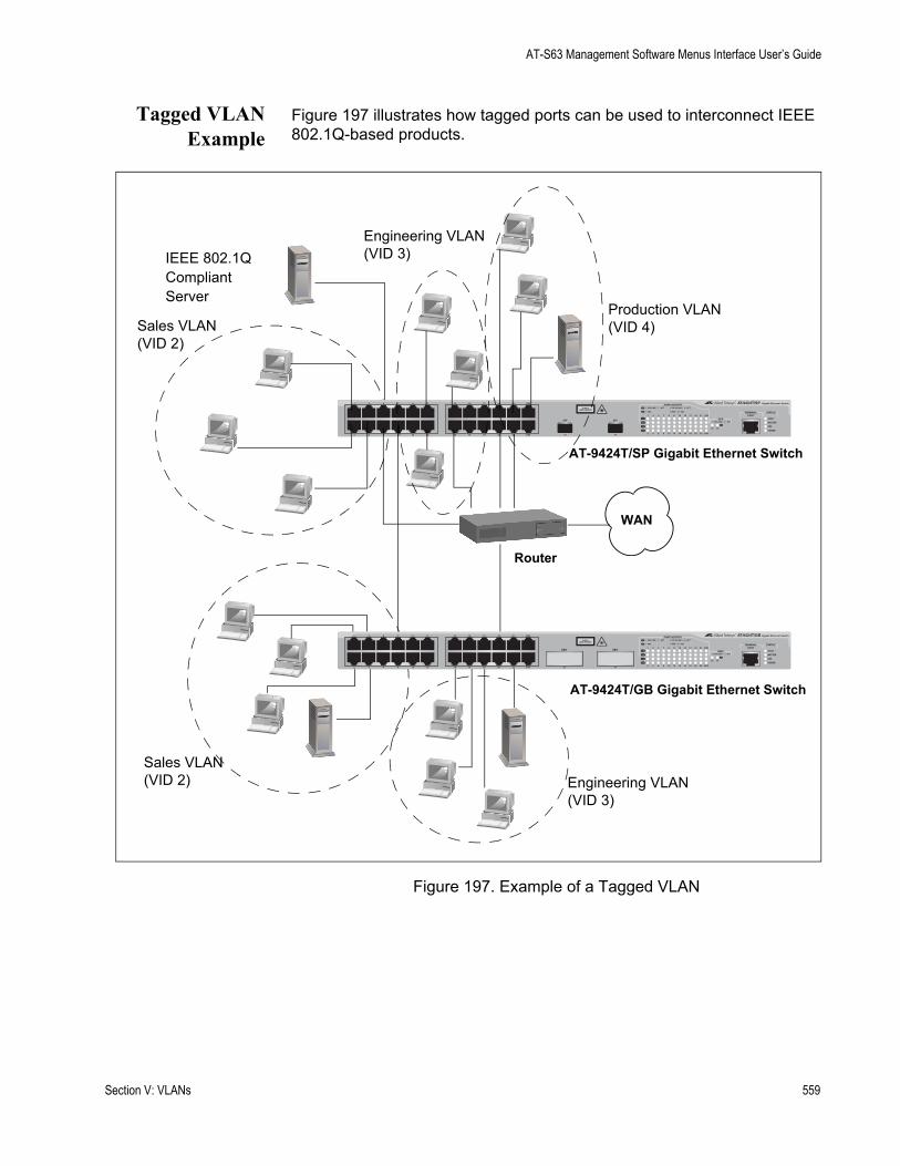
AT-S63 Management Software Menus Interface User’s Guide
Tagged VLANExample
Figure 197 illustrates how tagged ports can be used to interconnect IEEE 802.1Q-based products.
Figure 197. Example of a Tagged VLAN
Router
AT-9424T/SP Gigabit Ethernet Switch
WAN
FAULT
RPS
MASTER
POWER
CLASS 1LASER PRODUCT
STATUSTERMINALPORT
1 3 5 7 9 11
2 4 6 8 10 12
13 15 17 19 21 23R
14 16 18 20 22 24R
AT-9424T/SP Gigabit Ethernet Switch
1 3 5 7 9 11 13 15 17 19 21 23R
2 4 6 8 10 12 14 16 18 20 22 24R
23 24
L/A
D/C
D/C
L/A
D/C
L/A 1000 LINK / ACT
HDX / COLFDX
10/100 LINK / ACTPORT ACTIVITY
L/A
1000 LINK / ACTSFPSFP
24
SFP
23
Sales VLAN(VID 2)
Engineering VLAN(VID 3)
Production VLAN(VID 4)
Sales VLAN(VID 2) Engineering VLAN
(VID 3)
AT-9424T/GB Gigabit Ethernet Switch
FAULT
RPS
MASTER
POWER
GBIC
23
GBIC
24
CLASS 1LASER PRODUCT
STATUSTERMINALPORT
1 3 5 7 9 11
2 4 6 8 10 12
13 15 17 19 21 23R
14 16 18 20 22 24R
AT-9424T/GB Gigabit Ethernet Switch
1 3 5 7 9 11 13 15 17 19 21 23R
2 4 6 8 10 12 14 16 18 20 22 24R
23 24
L/A
D/C
D/C
L/A
D/C
L/A 1000 LINK / ACT
HDX / COLFDX
10/100 LINK / ACTPORT ACTIVITY
L/A
1000 LINK / ACTGBIC
IEEE 802.1QCompliant Server
Section V: VLANs 559
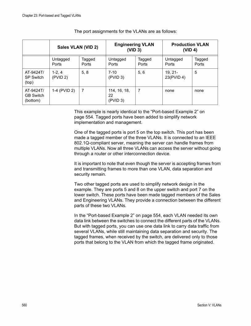
Chapter 23: Port-based and Tagged VLANs
The port assignments for the VLANs are as follows:
This example is nearly identical to the “Port-based Example 2” on page 554. Tagged ports have been added to simplify network implementation and management.
One of the tagged ports is port 5 on the top switch. This port has been made a tagged member of the three VLANs. It is connected to an IEEE 802.1Q-compliant server, meaning the server can handle frames from multiple VLANs. Now all three VLANs can access the server without going through a router or other interconnection device.
It is important to note that even though the server is accepting frames from and transmitting frames to more than one VLAN, data separation and security remain.
Two other tagged ports are used to simplify network design in the example. They are ports 5 and 8 on the upper switch and port 7 on the lower switch. These ports have been made tagged members of the Sales and Engineering VLANs. They provide a connection between the different parts of these two VLANs.
In the “Port-based Example 2” on page 554, each VLAN needed its own data link between the switches to connect the different parts of the VLANs. But with tagged ports, you can use one data link to carry data traffic from several VLANs, while still maintaining data separation and security. The tagged frames, when received by the switch, are delivered only to those ports that belong to the VLAN from which the tagged frame originated.
Sales VLAN (VID 2) Engineering VLAN(VID 3)
Production VLAN(VID 4)
Untagged Ports
Tagged Ports
Untagged Ports
Tagged Ports
Untagged Ports
Tagged Ports
AT-9424T/SP Switch (top)
1-2, 4(PVID 2)
5, 8 7-10(PVID 3)
5, 6 19, 21-23(PVID 4)
5
AT-9424T/GB Switch (bottom)
1-4 (PVID 2) 7 114, 16, 18, 22(PVID 3)
7 none none
560 Section V: VLANs
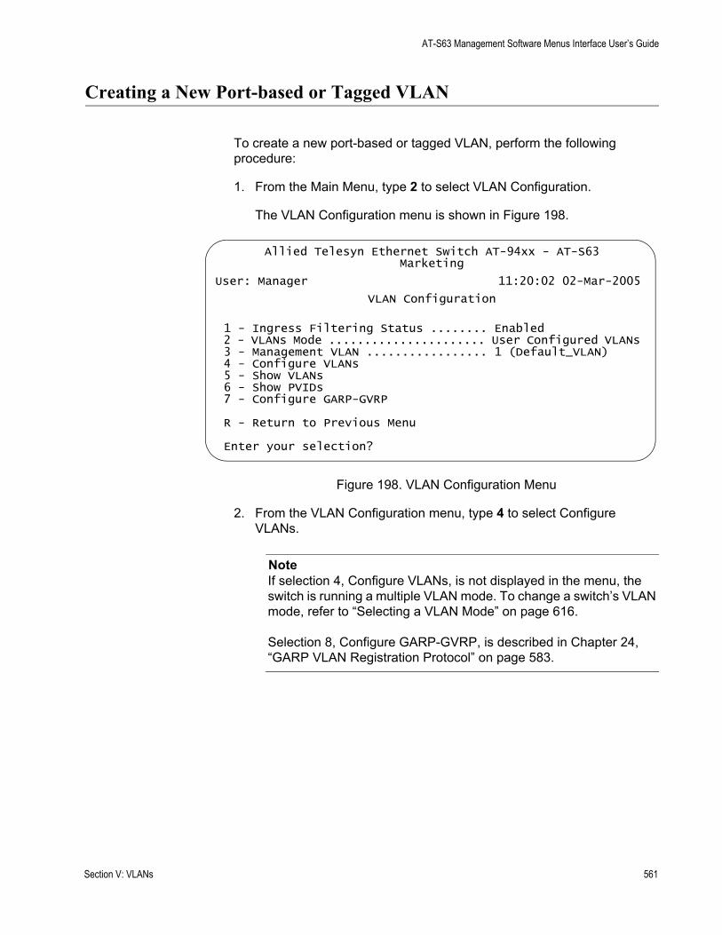
AT-S63 Management Software Menus Interface User’s Guide
Creating a New Port-based or Tagged VLAN
To create a new port-based or tagged VLAN, perform the following procedure:
1. From the Main Menu, type 2 to select VLAN Configuration.
The VLAN Configuration menu is shown in Figure 198.
Figure 198. VLAN Configuration Menu
2. From the VLAN Configuration menu, type 4 to select Configure VLANs.
NoteIf selection 4, Configure VLANs, is not displayed in the menu, the switch is running a multiple VLAN mode. To change a switch’s VLAN mode, refer to “Selecting a VLAN Mode” on page 616.
Selection 8, Configure GARP-GVRP, is described in Chapter 24, “GARP VLAN Registration Protocol” on page 583.
Allied Telesyn Ethernet Switch AT-94xx - AT-S63Marketing
User: Manager 11:20:02 02-Mar-2005
VLAN Configuration
1 - Ingress Filtering Status ........ Enabled2 - VLANs Mode ...................... User Configured VLANs3 - Management VLAN ................. 1 (Default_VLAN)4 - Configure VLANs5 - Show VLANs6 - Show PVIDs7 - Configure GARP-GVRP
R - Return to Previous Menu
Enter your selection?
Section V: VLANs 561
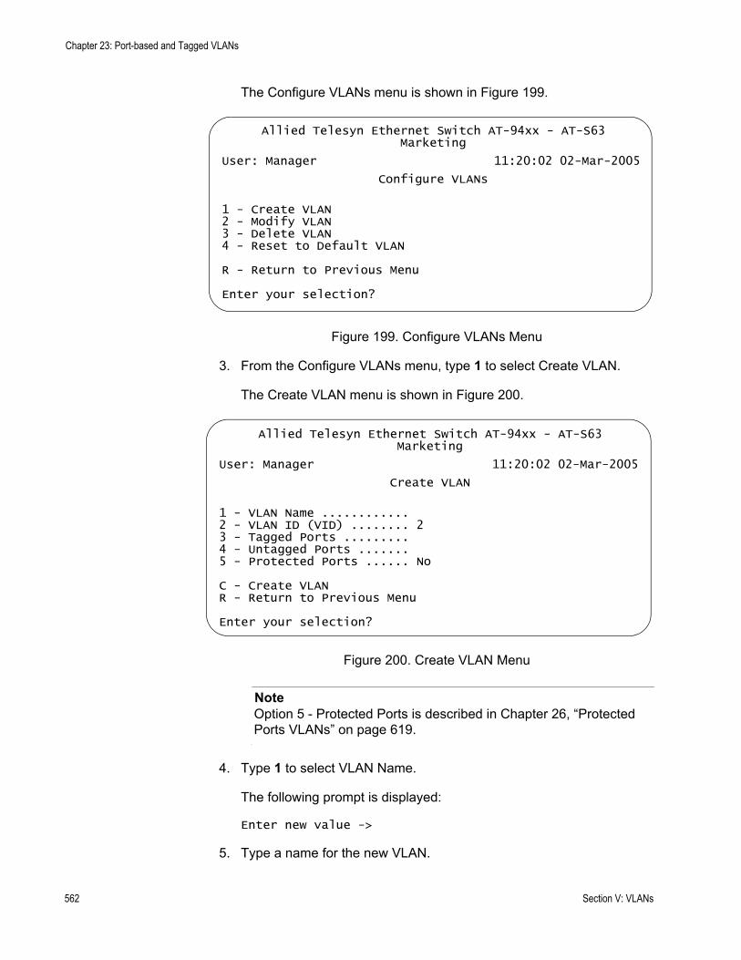
Chapter 23: Port-based and Tagged VLANs
The Configure VLANs menu is shown in Figure 199.
Figure 199. Configure VLANs Menu
3. From the Configure VLANs menu, type 1 to select Create VLAN.
The Create VLAN menu is shown in Figure 200.
Figure 200. Create VLAN Menu
NoteOption 5 - Protected Ports is described in Chapter 26, “Protected Ports VLANs” on page 619.
4. Type 1 to select VLAN Name.
The following prompt is displayed:
Enter new value ->
5. Type a name for the new VLAN.
Allied Telesyn Ethernet Switch AT-94xx - AT-S63Marketing
User: Manager 11:20:02 02-Mar-2005
Configure VLANs
1 - Create VLAN2 - Modify VLAN3 - Delete VLAN4 - Reset to Default VLAN
R - Return to Previous Menu
Enter your selection?
Allied Telesyn Ethernet Switch AT-94xx - AT-S63Marketing
User: Manager 11:20:02 02-Mar-2005
Create VLAN
1 - VLAN Name ............2 - VLAN ID (VID) ........ 23 - Tagged Ports .........4 - Untagged Ports .......5 - Protected Ports ...... No
C - Create VLANR - Return to Previous Menu
Enter your selection?
562 Section V: VLANs
AT-S63 Management Software Menus Interface User’s Guide
The name can be from one to fifteen alphanumeric characters in length. The name should reflect the function of the nodes that will be a part of the VLAN (for example, Sales or Accounting). The name cannot contain spaces or special characters, such as asterisks (*) or exclamation points (!).
If the VLAN will be unique in your network, then the name should be unique as well. If the VLAN will be part of a larger VLAN that spans multiple switches, then the name for the VLAN should be the same on each switch where nodes of the VLAN are connected.
NoteA VLAN must be assigned a name.
6. Type 2 to select VLAN ID (VID.
The following prompt is displayed:
Enter new value -> [2 to 4094] ->
7. Type a VID value for the new VLAN. The range for the VID value is 1 to 4094.
The AT-S63 management software uses the next available VID number on the switch as the default value. If this VLAN is unique in your network, then its VID should also be unique. If this VLAN is part of a larger VLAN that spans multiple switches, than the VID value for the VLAN should be the same on each switch. For example, if you are creating a VLAN called Sales that spans three switches, you should assign the Sales VLAN on each switch the same VID value.
NoteA VLAN must have a VID.
It is important to note that the switch is only aware of the VIDs of the VLANs that exist on the device, and not those that might already be in use in the network. For example, if you add a new AT-9400 Series switch to a network that already contains VLANs that use VIDs 2 through 24, the AT-S63 management software still uses VID 2 as the default value when you create the first VLAN on the new switch, even though that VID number is already being used by another VLAN on the network. To prevent inadvertently using the same VID for two different VLANs, you should keep a list of all your network VLANs and their VID values.
8. If the VLAN will contain tagged ports, type 3 to select Tagged Ports and specify the ports. If this VLAN will not contain any tagged ports, leave this field empty.
Section V: VLANs 563

Chapter 23: Port-based and Tagged VLANs
You can specify the ports individually (e.g., 2,3,5), as a range (e.g., 7-9), or both (e.g., 2,5,7-9).
9. Type 4 to select Untagged Ports and specify the ports on the switch to function as untagged ports in the VLAN. If this VLAN will not contain any untagged ports, leave this field empty.
You can specify the ports individually (e.g., 2,3,5), as a range (e.g., 7-9), or both (e.g., 2,5,7-9).
10. Type C to select Create VLAN.
The following message is displayed:
SUCCESS - Press any key to continue.
The AT-S63 management software creates the new VLAN. The new VLAN is now ready for network use.
11. Press any key.
The VLAN Configuration menu in Figure 198 on page 561 is redisplayed.
12. To verify that the VLAN was created correctly, type 6 to select Show VLANs.
13. Check to see that the VLAN contains the appropriate ports.
14. After making changes, type R until you return to the Main Menu. Then type S to select Save Configuration Changes.
15. Repeat this procedure to create additional VLANs.
NoteWhen you create a new VLAN, ports designated as untagged ports of the new VLAN are automatically removed from their current untagged VLAN assignment. For example, if you are creating a new VLAN on a switch that contains only the Default_VLAN, the ports that you specify as untagged ports of the new VLAN are automatically removed from the Default_VLAN.
Tagged ports are not removed from any current VLAN assignments because tagged ports can belong to more than one VLAN at a time.
564 Section V: VLANs
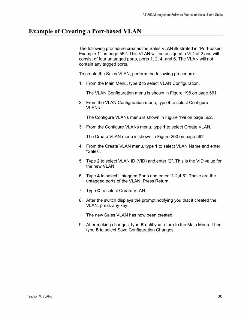
AT-S63 Management Software Menus Interface User’s Guide
Example of Creating a Port-based VLAN
The following procedure creates the Sales VLAN illustrated in “Port-based Example 1” on page 552. This VLAN will be assigned a VID of 2 and will consist of four untagged ports, ports 1, 2, 4, and 6. The VLAN will not contain any tagged ports.
To create the Sales VLAN, perform the following procedure:
1. From the Main Menu, type 2 to select VLAN Configuration.
The VLAN Configuration menu is shown in Figure 198 on page 561.
2. From the VLAN Configuration menu, type 4 to select Configure VLANs.
The Configure VLANs menu is shown in Figure 199 on page 562.
3. From the Configure VLANs menu, type 1 to select Create VLAN.
The Create VLAN menu is shown in Figure 200 on page 562.
4. From the Create VLAN menu, type 1 to select VLAN Name and enter “Sales”.
5. Type 2 to select VLAN ID (VID) and enter “2”. This is the VID value for the new VLAN.
6. Type 4 to select Untagged Ports and enter “1-2,4,6”. These are the untagged ports of the VLAN. Press Return.
7. Type C to select Create VLAN.
8. After the switch displays the prompt notifying you that it created the VLAN, press any key.
The new Sales VLAN has now been created.
9. After making changes, type R until you return to the Main Menu. Then type S to select Save Configuration Changes.
Section V: VLANs 565
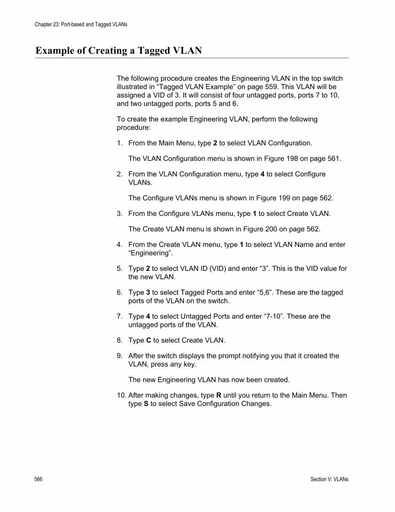
Chapter 23: Port-based and Tagged VLANs
Example of Creating a Tagged VLAN
The following procedure creates the Engineering VLAN in the top switch illustrated in “Tagged VLAN Example” on page 559. This VLAN will be assigned a VID of 3. It will consist of four untagged ports, ports 7 to 10, and two untagged ports, ports 5 and 6.
To create the example Engineering VLAN, perform the following procedure:
1. From the Main Menu, type 2 to select VLAN Configuration.
The VLAN Configuration menu is shown in Figure 198 on page 561.
2. From the VLAN Configuration menu, type 4 to select Configure VLANs.
The Configure VLANs menu is shown in Figure 199 on page 562.
3. From the Configure VLANs menu, type 1 to select Create VLAN.
The Create VLAN menu is shown in Figure 200 on page 562.
4. From the Create VLAN menu, type 1 to select VLAN Name and enter “Engineering”.
5. Type 2 to select VLAN ID (VID) and enter “3”. This is the VID value for the new VLAN.
6. Type 3 to select Tagged Ports and enter “5,6”. These are the tagged ports of the VLAN on the switch.
7. Type 4 to select Untagged Ports and enter “7-10”. These are the untagged ports of the VLAN.
8. Type C to select Create VLAN.
9. After the switch displays the prompt notifying you that it created the VLAN, press any key.
The new Engineering VLAN has now been created.
10. After making changes, type R until you return to the Main Menu. Then type S to select Save Configuration Changes.
566 Section V: VLANs
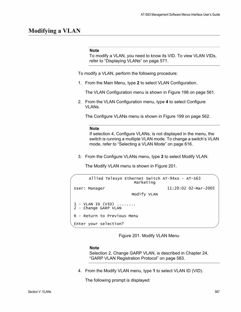
AT-S63 Management Software Menus Interface User’s Guide
Modifying a VLAN
NoteTo modify a VLAN, you need to know its VID. To view VLAN VIDs, refer to “Displaying VLANs” on page 571.
To modify a VLAN, perform the following procedure:
1. From the Main Menu, type 2 to select VLAN Configuration.
The VLAN Configuration menu is shown in Figure 198 on page 561.
2. From the VLAN Configuration menu, type 4 to select Configure VLANs.
The Configure VLANs menu is shown in Figure 199 on page 562.
NoteIf selection 4, Configure VLANs, is not displayed in the menu, the switch is running a multiple VLAN mode. To change a switch’s VLAN mode, refer to “Selecting a VLAN Mode” on page 616.
3. From the Configure VLANs menu, type 2 to select Modify VLAN.
The Modify VLAN menu is shown in Figure 201.
Figure 201. Modify VLAN Menu
NoteSelection 2, Change GARP VLAN, is described in Chapter 24, “GARP VLAN Registration Protocol” on page 583.
4. From the Modify VLAN menu, type 1 to select VLAN ID (VID).
The following prompt is displayed:
Allied Telesyn Ethernet Switch AT-94xx - AT-S63Marketing
User: Manager 11:20:02 02-Mar-2005
Modify VLAN
1 - VLAN ID (VID) ........ 2 - Change GARP VLAN
R - Return to Previous Menu
Enter your selection?
Section V: VLANs 567
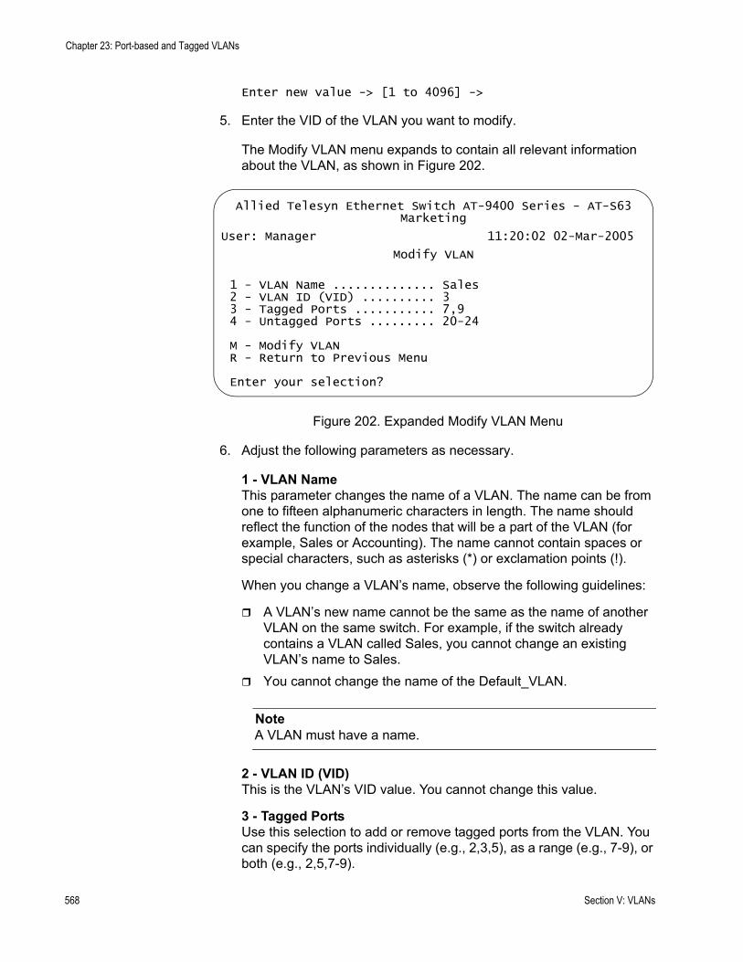
Chapter 23: Port-based and Tagged VLANs
Enter new value -> [1 to 4096] ->
5. Enter the VID of the VLAN you want to modify.
The Modify VLAN menu expands to contain all relevant information about the VLAN, as shown in Figure 202.
Figure 202. Expanded Modify VLAN Menu
6. Adjust the following parameters as necessary.
1 - VLAN NameThis parameter changes the name of a VLAN. The name can be from one to fifteen alphanumeric characters in length. The name should reflect the function of the nodes that will be a part of the VLAN (for example, Sales or Accounting). The name cannot contain spaces or special characters, such as asterisks (*) or exclamation points (!).
When you change a VLAN’s name, observe the following guidelines:
A VLAN’s new name cannot be the same as the name of another VLAN on the same switch. For example, if the switch already contains a VLAN called Sales, you cannot change an existing VLAN’s name to Sales.You cannot change the name of the Default_VLAN.
NoteA VLAN must have a name.
2 - VLAN ID (VID)This is the VLAN’s VID value. You cannot change this value.
3 - Tagged PortsUse this selection to add or remove tagged ports from the VLAN. You can specify the ports individually (e.g., 2,3,5), as a range (e.g., 7-9), or both (e.g., 2,5,7-9).
Allied Telesyn Ethernet Switch AT-9400 Series - AT-S63Marketing
User: Manager 11:20:02 02-Mar-2005
Modify VLAN
1 - VLAN Name .............. Sales2 - VLAN ID (VID) .......... 33 - Tagged Ports ........... 7,94 - Untagged Ports ......... 20-24
M - Modify VLANR - Return to Previous Menu
Enter your selection?
568 Section V: VLANs
AT-S63 Management Software Menus Interface User’s Guide
When you add or remove tagged ports, observe the following guidelines:
The new list of tagged ports will replace the existing tagged ports.If the VLAN contains tagged ports and you want to remove them all, enter 0 (zero) for this value.
4 - Untagged PortsUse this selection to add or remove untagged ports from the VLAN. You can specify the ports individually (e.g., 2,3,5), as a range (e.g., 7-9), or both (e.g., 2,5,7-9).
When you add or remove untagged ports, observe the following guidelines:
The new list of untagged ports will replace the existing untagged ports.If you want to remove all untagged ports from the VLAN, enter 0 (zero) for this value. You cannot change the name of the Default_VLAN, nor can you directly remove untagged ports from the Default_VLAN. Instead, you must assign the port as an untagged port to another VLAN.
An untagged port removed from a VLAN is automatically returned to the Default_VLAN as an untagged port.
7. After making the desired changes, type M to select Modify VLAN.
The following message is displayed:
SUCCESSPlease make sure to manually update any staticmulticast MAC address(es) entries for this VLAN.Press any key to continue...
The VLAN has been modified and is now ready for network operations.
Any untagged ports removed from a VLAN are automatically returned to the Default_VLAN as untagged ports.
If you added or removed from the VLAN a port with one or more static MAC addresses assigned to it, you must update the static addresses by deleting their entries from the MAC address table and reentering them again using the VID of the VLAN to which the port has been moved to. For information on how to add static MAC addresses, refer to “Adding Static Unicast and Multicast MAC Addresses” on page 678. For instructions on how to delete addresses, refer to “Deleting Unicast and Multicast MAC Addresses” on page 680.
8. Press any key.
The Modify VLAN menu in Figure 201 on page 567 is displayed again.
Section V: VLANs 569

Chapter 23: Port-based and Tagged VLANs
9. Repeat this procedure starting with Step 4 to modify other VLANs, or return to the Main Menu and type S to select Save Configuration Changes.
570 Section V: VLANs

AT-S63 Management Software Menus Interface User’s Guide
Displaying VLANs
To view the name, VID number, and member ports of all the VLANs on a switch, perform the following procedure:
1. From the Main Menu, type 2 to select VLAN Configuration.
The VLAN Configuration menu is shown in Figure 198 on page 561.
2. From the VLAN Configuration menu, type 5to select Show VLANs.
The Show VLANs menu is shown in Figure 203.
Figure 203. Show VLANs Menu
The Show VLANs menu displays a table that contains the following columns of information:
VIDThe VLAN ID.
VLAN NameName of the VLAN.
VLAN TypeThe VLAN type. The possible settings are:
Port Based - The VLAN is a port-based or tagged VLAN.
GARP - The VLAN was automatically created by GARP.
Allied Telesyn Ethernet Switch AT-94xx - AT-S63Marketing
User: Manager 11:20:02 02-Mar-2005
Show VLANs
VID VLAN Name VLAN Type Protocol Untagged (U) / Tagged (T)------------------------------------------------------------------
1 Default_VLAN Port Based U: 20-24Port Based T: 7,9
2 Sales Port Based U: 1-7Port Based T: 9
3 Production Port Based U: 8-19Port Based T: 7
N - Next PageU - Update DisplayR - Return to Previous Menu
Enter your selection?
Section V: VLANs 571

Chapter 23: Port-based and Tagged VLANs
ProtocolThe protocol associated with this VLAN. The possible settings are:
Blank - The VLAN is a port-based or tagged VLAN.
GARP - The VLAN is a dynamic GVRP VLAN or the port is a dynamic GVRP port of a static VLAN.
Untagged (U) / Tagged (T)The untagged and tagged ports that are part of the VLAN.
572 Section V: VLANs

AT-S63 Management Software Menus Interface User’s Guide
Deleting a VLAN
NoteTo delete a VLAN, you need to know its VID. To view VLAN VIDs, refer to “Displaying VLANs” on page 571.
To delete a VLAN, perform the following procedure:
1. From the Main Menu, type 2 to select VLAN Configuration.
The VLAN Configuration menu is shown in Figure 198 on page 561.
2. From the VLAN Configuration menu, type 4 to select Configure VLANs.
The Configure VLANs menu is shown in Figure 199 on page 562.
NoteIf option 4, Configure VLANs, is not displayed in the menu if the switch is running a multiple VLAN mode. To change a switch’s VLAN mode, refer to “Selecting a VLAN Mode” on page 616.
3. From the Configure VLANs menu, type 3 to select Delete VLAN.
The Delete VLAN menu is shown in Figure 204.
Figure 204. Delete VLAN Menu
4. From the Delete VLAN menu, type 1 to select VLAN ID (VID).
The following prompt is displayed:
Enter new value -> [2 to 4094] ->
5. Enter the VID of the VLAN you want to delete. You can specify only one VID at a time.
Allied Telesyn Ethernet Switch AT-94xx - AT-S63Marketing
User: Manager 11:20:02 02-Mar-2005
Delete VLAN
1 - VLAN ID (VID) ........
R - Return to Previous Menu
Enter your selection?
Section V: VLANs 573
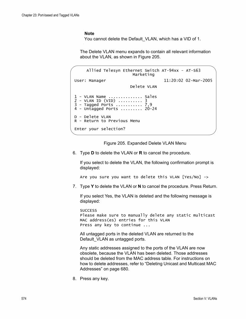
Chapter 23: Port-based and Tagged VLANs
NoteYou cannot delete the Default_VLAN, which has a VID of 1.
The Delete VLAN menu expands to contain all relevant information about the VLAN, as shown in Figure 205.
Figure 205. Expanded Delete VLAN Menu
6. Type D to delete the VLAN or R to cancel the procedure.
If you select to delete the VLAN, the following confirmation prompt is displayed:
Are you sure you want to delete this VLAN [Yes/No] ->
7. Type Y to delete the VLAN or N to cancel the procedure. Press Return.
If you select Yes, the VLAN is deleted and the following message is displayed:
SUCCESSPlease make sure to manually delete any static multicast MAC address(es) entries for this VLANPress any key to continue ...
All untagged ports in the deleted VLAN are returned to the Default_VLAN as untagged ports.
Any static addresses assigned to the ports of the VLAN are now obsolete, because the VLAN has been deleted. Those addresses should be deleted from the MAC address table. For instructions on how to delete addresses, refer to “Deleting Unicast and Multicast MAC Addresses” on page 680.
8. Press any key.
Allied Telesyn Ethernet Switch AT-94xx - AT-S63Marketing
User: Manager 11:20:02 02-Mar-2005
Delete VLAN
1 - VLAN Name .............. Sales2 - VLAN ID (VID) .......... 33 - Tagged Ports ........... 7,94 - Untagged Ports ......... 20-24
D - Delete VLANR - Return to Previous Menu
Enter your selection?
574 Section V: VLANs

AT-S63 Management Software Menus Interface User’s Guide
9. Repeat this procedure starting with Step 4 to delete other VLANs.
10. After making changes, type R until you return to the Main Menu. Then type S to select Save Configuration Changes.
Section V: VLANs 575

Chapter 23: Port-based and Tagged VLANs
Resetting to the Default VLAN
The following procedure for deletes all VLANs, except the Default_VLAN, on a switch. To delete selected VLANs, perform the procedure in “Deleting a VLAN” on page 573.
To return all ports to the default VLAN, perform the following procedure:
1. From the Main Menu, type 2 to select VLAN Configuration.
The VLAN Configuration menu is shown in Figure 198 on page 561.
2. From the VLAN Configuration menu, type 4 to select Configure VLANs.
The Configure VLANs menu is shown in Figure 199 on page 562.
NoteIf selection 4, Configure VLANs, is not displayed in the menu, the switch is running in a multiple VLAN mode. To change a switch’s VLAN mode, refer to “Selecting a VLAN Mode” on page 616.
3. From the Configure VLANs menu, type 4 to select Reset to Default VLAN.
The following prompt is displayed:
This operation deletes ALL user created VLANs!Do you want to continue [Yes/No] ->
4. Type Y to delete all VLANs or N to cancel the procedure. Press Return.
If you select Yes, all VLANs are deleted and the following message is displayed:
SUCCESSPlease make sure to manually update any staticmulticast MAC address(es) entries.Press any key to continue...
All tagged and untagged ports are returned to the Default_VLAN as untagged ports.
Any static addresses assigned to the ports of the VLANs are now obsolete, except for the Default_VLAN, because the VLANs have been deleted. Those addresses should be deleted from the MAC address table. For instructions on how to delete addresses, refer to “Deleting All Dynamic MAC Addresses” on page 681.
5. Press any key.
576 Section V: VLANs

AT-S63 Management Software Menus Interface User’s Guide
6. After making changes, type R until you return to the Main Menu. Then type S to select Save Configuration Changes.
Section V: VLANs 577

Chapter 23: Port-based and Tagged VLANs
Displaying PVIDs
The following procedure displays a menu that lists the PVIDs for all the ports on the switch.
To display the PVID settings on the switch, perform the following procedure:
1. From the Main Menu, type 2 to select VLAN Configuration.
The VLAN Configuration menu is shown in Figure 198 on page 561.
2. From the VLAN Configuration menu, type 6 to select Show PVIDs.
The Show PVIDs menu is shown in Figure 206.
Figure 206. Show PVIDs Menu
The PVID column displays the current PVID value for each switch port.
Allied Telesyn Ethernet Switch AT-94xx - AT-S63Marketing
User: Manager 11:20:02 02-Mar-2005
Show PVIDs
Port PVID---------------------------------------------------------01 2202 2203 104 105 106 107 2408 24
N - Next PageU - Update DisplayR - Return to Previous Menu
Enter your selection?
578 Section V: VLANs
AT-S63 Management Software Menus Interface User’s Guide
Enabling or Disabling Ingress Filtering
There are rules a switch follows when it receives and forwards an Ethernet frame. There are rules for frames as they enter a port (called ingress rules) and rules for when a frame is transmitted out a port (called egress rules). A switch does not accept and forward a frame unless the frame passes the ingress and egress rules.
There are many ingress and egress rules for Gigabit Ethernet switches. T this discussion reviews only the rules as they apply to tagged frames, because ingress filtering does not apply to untagged frames.
First, as a reminder, a tagged frame is an Ethernet frame that contains a tagged header. The header contains the VID of the VLAN to which the frame originated. For further information, refer to “Tagged VLAN Overview” on page 556.
The ingress rules are applied to tagged frames when ingress filtering is activated. The switch examines the tagged header of each tagged frame that enters a port and determines whether the tagged frame and the port that received the frame are members of the same VLAN. If they belong to the same VLAN, the port accepts the frame. If they belong to different VLANs, the port discards the frame.
As an example, assume that a tagged frame with a VID of 4 is received on a port that is a member of a VLAN also with a VID of 4. In this case, the port accepts the frame, because both the frame and the port belong to the same VLAN. If the frame and port belong to different VLANs, the frame is discarded.
How do the egress rules apply when ingress filtering is disabled? First, any tagged frame is accepted on any port on the switch. It does not matter whether the frame and the port belong to the same or different VLANs.
After the tagged frame is received, the switch examines the tagged header and determines if the VID in the header corresponds to any VLANs on the switch. If there is no corresponding VLAN, the switch discards the frame. If there is, the switch transmits the frame out the port to the destination node, assuming that the destination node’s MAC address is in the MAC address table, or floods the port to all ports on the VLAN if the MAC address is not in the table.
In addition, each tagged frame contains a priority tag that informs the switch about the importance of the frame. Frames with a high priority are handled ahead of frames with a low priority.
Activating or deactivating ingress filtering has no effect on the switch’s handling of priority tags. A switch will always examines a priority tag in a tagged frame, without regard to the status of ingress filtering.
Section V: VLANs 579
Chapter 23: Port-based and Tagged VLANs
In most cases, you will probably want to leave ingress filtering activated on the switch, which is the default. You can enable or disable ingress filtering on a per switch basis. You cannot set this per port.
To enable or disable ingress filtering, perform the following procedure:
1. From the Main Menu, type 2 to select VLAN Configuration.
The VLAN Configuration menu is shown in Figure 198 on page 561.
2. From the VLAN Configuration menu, type 1 to select Ingress Filtering Status.
The following prompt is displayed:
Enter Ingress Filtering Status (E-Enable, D-Disable) ->
3. Type E to activate ingress filtering or D to disable the feature on the switch.
A change to the status of ingress filtering is immediately activated on the switch.
4. After making changes, type R until you return to the Main Menu. Then type S to select Save Configuration Changes.
580 Section V: VLANs
AT-S63 Management Software Menus Interface User’s Guide
Specifying a Management VLAN
The management VLAN is the VLAN on which an AT-9400 Series switch expects to receive management packets. This VLAN is important if you will be managing a switch remotely or using the enhanced stacking feature of the switch.
Management packets are packets generated by a management station when you manage a switch using the Telnet application protocol or a web browser. The switch acts upon the management packets only if they are received on the management VLAN.
The default management VLAN on an AT-9400 Series switch is the Default_VLAN. If you do not create any additional VLANs and link the switches together using untagged ports, then there is no need to specify a new management VLAN in order to remotely manage the devices.
However, if you create additional VLANs on your switches, it may be necessary for you to create a management communications path and then specify that path as the new management VLAN.
Below are several rules to observe when using this feature:
The management VLAN must exist on each AT-9400 Series switch that you want to manage.Using the following procedure, you must specify the management VLAN in the AT-S63 management software on each slave and master switch of an enhanced stack.The uplink and downlink ports on each switch that are functioning as the tagged or untagged data links between the switches must be either tagged or untagged members of the management VLAN.The port on the switch to which the management station is connected must be a member of the management VLAN. (This rule does not apply when managing the switch locally through the RJ-45 terminal port.)
As an example, assume that you have an enhanced stack of seven AT-9400 Series switches with one master switch. If the uplink and downlink ports between the various switches are members of the Default_VLAN and if the management station is connected to a port of the Default_VLAN, you can manage all the switches because the Default_VLAN is the default management VLAN.
Now assume that you decide to create a VLAN called NMS with a VID of 24 for the sole purpose of remote network management. For this, you need to create the NMS VLAN on each AT-9400 Series switch that you want to manage remotely, being sure to assign each NMS VLAN the VID of 24. Then you need to be sure that the uplink and downlink ports
Section V: VLANs 581

Chapter 23: Port-based and Tagged VLANs
connecting the switches together are either tagged or untagged members of the NMS VLAN. You also need to specify the NMS VLAN as the management VLAN on each switch using the AT-S63 management software. Finally, you must be sure to connect your management station to a port on a switch that is a tagged or untagged member of the management VLAN.
NoteYou cannot specify a management VLAN when the switch is operating in a multiple VLAN mode.
To specify a management VLAN, perform the following procedure:
1. From the Main Menu, type 2 to select VLAN Configuration.
The VLAN Configuration menu is shown in Figure 198 on page 561.
2. From the VLAN Configuration menu, type 3 to select Management VLAN.
The following prompt is displayed:
Enter Management VLAN ID [1 to 4094] ->
3. Specify the VID of the VLAN that is to function as the management VLAN. This VLAN must already exist on the switch.
The following prompt is displayed:
SUCCESSPress any key to continue ...
4. Press any key.
5. After making changes, type R until you return to the Main Menu. Then type S to select Save Configuration Changes.
582 Section V: VLANs
Chapter 24
GARP VLAN Registration Protocol
This chapter describes the GARP VLAN Registration Protocol (GVRP) and contains the following sections:
“GARP VLAN Registration Protocol (GVRP) Overview” on page 584“Configuring GVRP” on page 592“Enabling or Disabling GVRP on a Port” on page 594“Displaying the GVRP Port Configuration” on page 596“Displaying GVRP Counters” on page 597“Displaying the GVRP Database” on page 602“Displaying the GIP Connected Ports Ring” on page 604“Displaying the GVRP State Machine” on page 606
Section V: VLANs 583
Chapter 24: GARP VLAN Registration Protocol
GARP VLAN Registration Protocol (GVRP) Overview
The GARP VLAN Registration Protocol (GVRP) allows network devices to share VLAN information. The main purpose of GVRP is to allow switches to automatically discover some of the VLAN information that would otherwise need to be manually configured in each switch. This is helpful in networks where VLANs span more than one switch. Without GVRP, you must manually configure your switches to ensure that the various parts of a VLAN can communicate across the different switches. GVRP, which is an application of the Generic Attribute Registration Protocol (GARP), does this for you automatically.
The AT-S63 management software uses GVRP protocol data units (PDUs) to share VLAN information among GVRP-active devices. The PDUs contain the VID numbers of the VLANs on the switch. A PDU contains the VIDs of all the VLANs on the switch, not just the VID of which the transmitting port is a member.
When a switch receives a GVRP PDU on a port, it examines the PDU to determine the VIDs of the VLANs on the device that sent it. It then does the following:
If the VLAN does not exist on the switch, it creates the VLAN and adds the port as a tagged member to the VLAN. A VLAN created by GVRP is called a dynamic GVRP VLAN. If the VLAN already exists on the switch but the port is not a member of it, the switch adds the port as a tagged member. A port that has been added by GVRP to a static VLAN (that is a user-created VLAN) is called a dynamic GVRP port.
You cannot modify a dynamic GVRP VLAN. After it is created, only GVRP can modify or delete it. A dynamic GVRP VLAN exists only so long as there are active nodes in the network that belong to the VLAN. If all nodes of a dynamic GVRP VLAN are shut down and there are no active links, the VLAN is deleted from the switch.
A dynamic GVRP port in a static VLAN remains a member of the VLAN as long as there are active VLAN members. If all members of the VLAN become inactive or there are no active links, GVRP removes the dynamic port from the VLAN, but does not delete the VLAN if the VLAN is a static VLAN.
584 Section V: VLANs
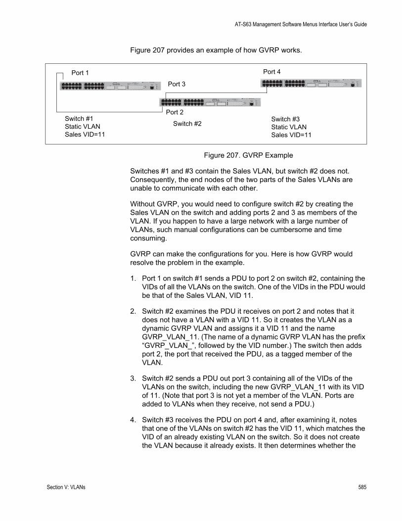
AT-S63 Management Software Menus Interface User’s Guide
Figure 207 provides an example of how GVRP works.
Figure 207. GVRP Example
Switches #1 and #3 contain the Sales VLAN, but switch #2 does not. Consequently, the end nodes of the two parts of the Sales VLANs are unable to communicate with each other.
Without GVRP, you would need to configure switch #2 by creating the Sales VLAN on the switch and adding ports 2 and 3 as members of the VLAN. If you happen to have a large network with a large number of VLANs, such manual configurations can be cumbersome and time consuming.
GVRP can make the configurations for you. Here is how GVRP would resolve the problem in the example.
1. Port 1 on switch #1 sends a PDU to port 2 on switch #2, containing the VIDs of all the VLANs on the switch. One of the VIDs in the PDU would be that of the Sales VLAN, VID 11.
2. Switch #2 examines the PDU it receives on port 2 and notes that it does not have a VLAN with a VID 11. So it creates the VLAN as a dynamic GVRP VLAN and assigns it a VID 11 and the name GVRP_VLAN_11. (The name of a dynamic GVRP VLAN has the prefix “GVRP_VLAN_”, followed by the VID number.) The switch then adds port 2, the port that received the PDU, as a tagged member of the VLAN.
3. Switch #2 sends a PDU out port 3 containing all of the VIDs of the VLANs on the switch, including the new GVRP_VLAN_11 with its VID of 11. (Note that port 3 is not yet a member of the VLAN. Ports are added to VLANs when they receive, not send a PDU.)
4. Switch #3 receives the PDU on port 4 and, after examining it, notes that one of the VLANs on switch #2 has the VID 11, which matches the VID of an already existing VLAN on the switch. So it does not create the VLAN because it already exists. It then determines whether the
FAULT
RPS
MASTER
POWER
GBIC
23
GBIC
24
CLASS 1LASER PRODUCT
STATUSTERMINALPORT
1 3 5 7 9 11
2 4 6 8 10 12
13 15 17 19 21 23R
14 16 18 20 22 24R
AT-9424T/GB Gigabit Ethernet Switch
1 3 5 7 9 11 13 15 17 19 21 23R
2 4 6 8 10 12 14 16 18 20 22 24R
23 24
L/A
D/C
D/C
L/A
D/C
L/A 1000 LINK / ACT
HDX / COLFDX
10/100 LINK / ACTPORT ACTIVITY
L/A
1000 LINK / ACTGBIC
Port 1
Port 2
Port 4
Port 3
Switch #3Static VLANSales VID=11
Switch #1Static VLANSales VID=11
Switch #2
Section V: VLANs 585
Chapter 24: GARP VLAN Registration Protocol
port that received the PDU, in this case port 4, is a member of the VLAN. If it is not a member, it automatically adds the port to the VLAN as an tagged dynamic GVRP port. If the port is already a member of the VLAN, then no change is made.
5. Switch #3 sends a PDU out port 4 to switch #2.
6. Switch #2 receives the PDU on port 3 and then adds the port as a tagged dynamic GVRP port to the dynamic GVRP_VLAN_11 VLAN.
There is now a communications path for the end nodes of the Sales VLAN on switches #1 and #3. GVRP created the new GVRP_VLAN_11 dynamic GVRP VLAN with a VID of 11 on switch #2 and added ports 2 and 3 to the VLAN as tagged dynamic GVRP ports.
Guidelines Following are guidelines to observe when using this feature:
GVRP is supported with STP and RSTP, or without spanning tree. However, GVRP is not supported with MSTP.GVRP is supported when the switch is operating in the tagged VLAN mode, which is the VLAN mode for creating your own tagged and port-based VLANs.GVRP is not supported when the switch is operating in either of the multiple VLAN modes.Both ports that constitute a data link between the switch and the other device must be running GVRP.You cannot modify or delete a dynamic GVRP VLAN.You cannot remove a dynamic GVRP port from a static or dynamic VLAN.GVRP is only aware of those VLANs that have active nodes, or where at least one end node of a VLAN has established a valid link with a switch. GVRP is not aware of a VLAN if there are no active end nodes or if no end nodes have established a link with the switch.Resetting a switch erases all dynamic GVRP VLANs and dynamic GVRP port assignments. The switch relearns the dynamic assignments as it receives PDUs from the other switches.GVRP has three timers that you can set: join timer, leave timer, and leave all timer. The values for these timers must be set the same on all switches running GVRP. Timers with different values on different switches can result in GVRP compatibility problems.You can convert dynamic GVRP VLANs and dynamic GVRP port assignments to static VLANs and static port assignments. The procedure for this is found in “Modifying a VLAN” on page 567. The default port settings on the switch for GVRP is active, meaning that the ports participate in GVRP. Allied Telesyn recommends
586 Section V: VLANs
AT-S63 Management Software Menus Interface User’s Guide
disabling GVRP on those ports that are connected to GVRP-inactive devices, meaning that they do not feature GVRP.PDUs are transmitted to only those switch ports where GVRP is enabled.
GVRP andNetwork Security
Use GVRP with caution because it can expose your network to unauthorized access. A network intruder can access restricted parts of the network by connecting to a switch port running GVRP and transmitting a bogus GVRP PDU containing VIDs of restricted VLANs. GVRP would make the switch port a member of the VLANs and that could give the intruder access to restricted areas of your network.
To protect against this type of network intrusion, consider the following:
Activating GVRP only on those switch ports that are connected to other devices that support GVRP. Do not activate GVRP on ports that are connected to GVRP-inactive devices.Converting all dynamic GVRP VLANs and dynamic GVRP ports to static assignments, and then turning off GVRP on all switches. This preserves the new VLAN assignments while protecting against network intrusion.
GVRP-inactiveIntermediate
Switches
If two GVRP-active devices are separated by a GVRP-inactive switch, the GVRP-active devices may not be able to share VLAN information. There are two issues involved.
The first is whether the intermediate switch forwards the GVRP PDUs that it receives from the GVRP-active switches. GVRP PDUs are management frames, intended for a switch’s CPU. In all likelihood, a GVRP-inactive switch discards the PDUs because it does not recognize them.
The second issue is that even if the GVRP-inactive switch forwards GVRP PDUs, it does not create the VLANs, at least not automatically. Consequently, even if the GVRP-active switches receive the PDUs and create the necessary VLANs, the intermediate switch may block the VLAN traffic, unless you modify its VLANs and port assignments manually.
Generic AttributeRegistration
Protocol (GARP)Overview
The following is a technical overview of GARP. An understanding of GARP may prove helpful when you use GVRP.
The purpose of the Generic Attribute Registration Protocol (GARP) is to provide a generic framework whereby devices in a bridged LAN, for example end stations and switches, can register and deregister attribute values, such as VLAN Identifiers, with each other. In doing so, the attributes are propagated to devices in the bridged LAN, and these devices form a “reachability” tree that is a subset of an active topology. For a bridged LAN, the active topology is normally that created and maintained by the Spanning Tree Protocol (STP).
Section V: VLANs 587
Chapter 24: GARP VLAN Registration Protocol
To use GARP, a GARP application must be defined. The Layer 2 switch has one GARP application presently implemented, GVRP.
The GARP application specifies what the attribute represents.
GARP defines the architecture, rules of operation, state machines and variables for the registration and deregistration of attribute values. By itself, GARP is not directly used by devices in a bridged LAN. It is the applications of GARP that perform meaningful actions. The use of GVRP allows dynamic filter entries for VLAN membership to be distributed among the forwarding databases of VLAN-active switches.
A GARP participant in a switch or an end station consists of a GARP application component, and a GARP Information Declaration (GID) component associated with each port of the switch. One such GARP participant exists per port, per GARP application. The GARP Information Propagation (GIP) component propagates information between GARP participants for the same application in a switch. Protocol exchanges take place between GARP participants by means of LLC Type 1 services, using the group MAC address and PDU format defined for the GARP application concerned.
Every instance of a GARP application includes a database to store the values of the attributes. Within GARP, attributes are mapped to GID indexes.
588 Section V: VLANs
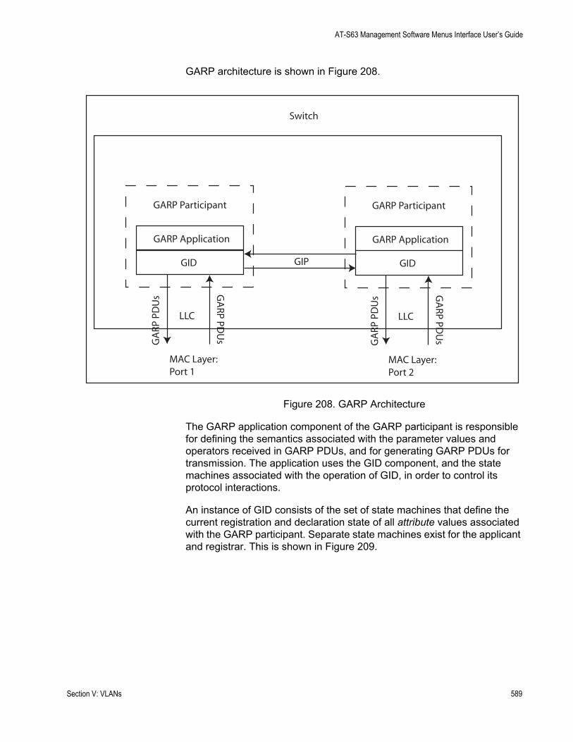
AT-S63 Management Software Menus Interface User’s Guide
GARP architecture is shown in Figure 208.
Figure 208. GARP Architecture
The GARP application component of the GARP participant is responsible for defining the semantics associated with the parameter values and operators received in GARP PDUs, and for generating GARP PDUs for transmission. The application uses the GID component, and the state machines associated with the operation of GID, in order to control its protocol interactions.
An instance of GID consists of the set of state machines that define the current registration and declaration state of all attribute values associated with the GARP participant. Separate state machines exist for the applicant and registrar. This is shown in Figure 209.
Switch
GARP Application
GID
GA
RP P
DU
s GA
RP PDU
sMAC Layer:Port 1
LLC
GARP Participant
GARP Application
GID
GA
RP P
DU
s GA
RP PDU
s
MAC Layer:Port 2
LLC
GARP Participant
GIP
Section V: VLANs 589

Chapter 24: GARP VLAN Registration Protocol
Figure 209. GID Architecture
GARP registers and deregisters attribute values through GARP messages sent at the GID level. A GARP participant that wishes to make a declaration (an applicant registering an attribute value) sends a JoinIn or JoinEmpty message. An applicant that wishes to withdraw a declaration (deregistering an attribute value) sends a LeaveEmpty or LeaveIn message. Following the de-registration of an attribute value, the applicant sends a number of Empty messages. The purpose of the Empty message is to prompt other applicants to send JoinIn/JoinEmpty messages. For the GARP protocol to be resilient against multiple lost messages, a LeaveAll message is available. Timers are used in the state machines to generate events and control state transitions.
The job of the applicant is twofold:
To ensure that this participant’s declarations are registered by other participants’ registrarsTo ensure that other participants have a chance to redeclare (rejoin) after anyone withdraws a declaration (leaves).
The applicant is therefore looking after the interests of all would-be participants. This allows the registrar to be very simple.
The job of the registrar is to record whether an attribute is registered, in the process of being deregistered, or is not registered for an instance of GID.
Attribute ... state:
Attribute C state:
Attribute A state:
ApplicantState
RegistrarState
Attribute B state:
GID
590 Section V: VLANs
AT-S63 Management Software Menus Interface User’s Guide
To control the applicant state machine, an applicant administrative control parameter is provided. This parameter determines whether or not the applicant state machine participates in GARP protocol exchanges. The default value has the applicant participating in the exchanges.
To control the registrar state machine, a registrar administrative control parameter is provided. This parameter determines whether or not the registrar state machine listens to incoming GARP messages. The default value has the registrar listening to incoming GARP messages.
The propagation of information between GARP participants for the same application in a switch is carried out by the GIP component. The operation of GIP is dependent upon STP being enabled on a port, because only ports in the STP Forwarding state are eligible for membership to the GIP connected ring. Ports in the GIP connected ring propagate GID Join and Leave requests to notify each other of attribute registrations and deregistrations. The operation of GIP allows ports in the switch to share information between themselves and the LANs/end stations to which the ports are connected.
If a port enters the STP Forwarding state and the GARP application that the port belongs to is enabled, then the port is added to the GIP connected ring for the GARP application. All attributes registered by other ports in the GIP connected ring is propagated to the recently connected port. All attributes registered by the recently connected port is propagated to all other ports in the GIP connected ring.
Similarly, if a port leaves the STP Forwarding state and the GARP application that the port belongs to is enabled, then the port is removed from the GIP connected ring for the GARP application. Prior to removal, GID leave requests are propagated to all other ports in the GIP connected ring if the port to be removed has previously registered an attribute and no other port in the GIP connected ring has registered that attribute. You can enable or disable GIP operations.
Section V: VLANs 591
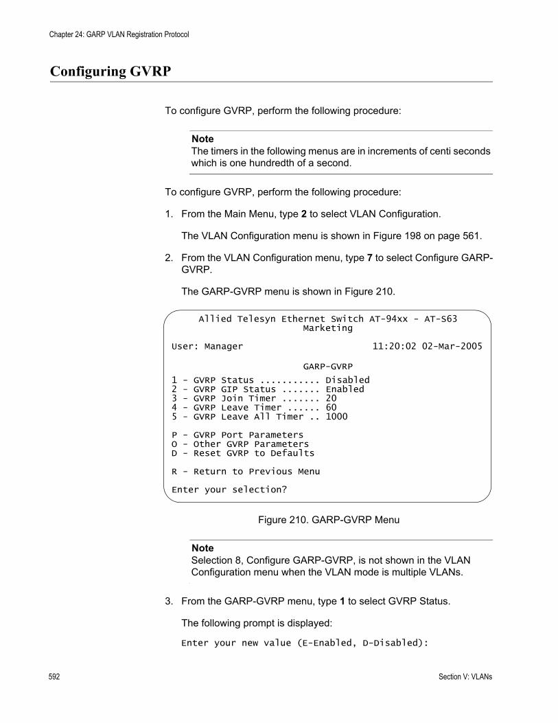
Chapter 24: GARP VLAN Registration Protocol
Configuring GVRP
To configure GVRP, perform the following procedure:
NoteThe timers in the following menus are in increments of centi seconds which is one hundredth of a second.
To configure GVRP, perform the following procedure:
1. From the Main Menu, type 2 to select VLAN Configuration.
The VLAN Configuration menu is shown in Figure 198 on page 561.
2. From the VLAN Configuration menu, type 7 to select Configure GARP-GVRP.
The GARP-GVRP menu is shown in Figure 210.
Figure 210. GARP-GVRP Menu
NoteSelection 8, Configure GARP-GVRP, is not shown in the VLAN Configuration menu when the VLAN mode is multiple VLANs.
3. From the GARP-GVRP menu, type 1 to select GVRP Status.
The following prompt is displayed:
Enter your new value (E-Enabled, D-Disabled):
Allied Telesyn Ethernet Switch AT-94xx - AT-S63Marketing
User: Manager 11:20:02 02-Mar-2005
GARP-GVRP
1 - GVRP Status ........... Disabled2 - GVRP GIP Status ....... Enabled3 - GVRP Join Timer ....... 204 - GVRP Leave Timer ...... 605 - GVRP Leave All Timer .. 1000
P - GVRP Port ParametersO - Other GVRP ParametersD - Reset GVRP to Defaults
R - Return to Previous Menu
Enter your selection?
592 Section V: VLANs
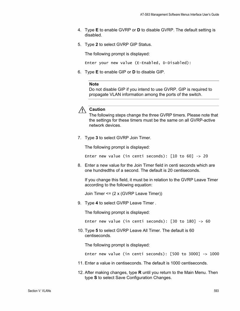
AT-S63 Management Software Menus Interface User’s Guide
4. Type E to enable GVRP or D to disable GVRP. The default setting is disabled.
5. Type 2 to select GVRP GIP Status.
The following prompt is displayed:
Enter your new value (E-Enabled, D-Disabled):
6. Type E to enable GIP or D to disable GIP.
NoteDo not disable GIP if you intend to use GVRP. GIP is required to propagate VLAN information among the ports of the switch.
CautionThe following steps change the three GVRP timers. Please note that the settings for these timers must be the same on all GVRP-active network devices.
7. Type 3 to select GVRP Join Timer.
The following prompt is displayed:
Enter new value (in centi seconds): [10 to 60] -> 20
8. Enter a new value for the Join Timer field in centi seconds which are one hundredths of a second. The default is 20 centiseconds.
If you change this field, it must be in relation to the GVRP Leave Timer according to the following equation:
Join Timer <= (2 x (GVRP Leave Timer))
9. Type 4 to select GVRP Leave Timer .
The following prompt is displayed:
Enter new value (in centi seconds): [30 to 180] -> 60
10. Type 5 to select GVRP Leave All Timer. The default is 60 centiseconds.
The following prompt is displayed:
Enter new value (in centi seconds): [500 to 3000] -> 1000
11. Enter a value in centiseconds. The default is 1000 centiseconds.
12. After making changes, type R until you return to the Main Menu. Then type S to select Save Configuration Changes.
Section V: VLANs 593

Chapter 24: GARP VLAN Registration Protocol
Enabling or Disabling GVRP on a Port
This procedure enables and disables GVRP on a switch port. The default setting for GVRP on a port is enabled. Only those ports where GVRP is enabled transmit PDUs.
NoteAllied Telesyn recommends disabling GVRP on unused ports and those ports that are connected to GVRP-inactive devices. This protects against unauthorized access to restricted areas of your network. For further information, refer to “GVRP and Network Security” on page 587.
To enable or disable GVRP on a port, perform the following procedure:
1. From the Main Menu, type 2 to select VLAN Configuration.
The VLAN Configuration menu is shown in Figure 198 on page 561.
2. From the VLAN Configuration menu, type 7 to select Configure GARP-GVRP.
The GARP-GVRP menu is shown in Figure 210 on page 592.
3. From the GARP-GVRP menu, type P to select GVRP Port Parameters.
The GVRP Port Parameters menu is shown in Figure 211.
Figure 211. GVRP Port Parameters Menu
4. From the GVRP Port Parameters menu, type 1 to select Configure GVRP Port Settings.
The following prompt is displayed:
Allied Telesyn Ethernet Switch AT-94xx - AT-S63Marketing
User: Manager 11:20:02 02-Mar-2005
GVRP Port Parameters
1 - Configure GVRP Port Settings2 - Display GVRP Port Configuration
R - Return to Previous Menu
Enter your selection?
594 Section V: VLANs

AT-S63 Management Software Menus Interface User’s Guide
Enter port-list:
5. Enter a port or a list of ports.
The Configure GVRP Port Settings menu is shown in Figure 212.
Figure 212. Configure GVRP Port Settings Menu
6. Type 1 to select Port Mode.
The following prompt is displayed:
Enter mode (0-Normal, 1-None): [0 to 1] -> 0
7. Type 0 to select Normal or 1 to select None. A setting of Normal means the port processes and propagates GVRP information. This is the default setting. A setting of None prevents the port from processing GVRP information and from transmitting PDUs.
8. After making changes, type R until you return to the Main Menu. Then type S to select Save Configuration Changes.
Allied Telesyn Ethernet Switch AT-94xx - AT-S63Marketing
User: Manager 11:20:02 02-Mar-2005
Configure GVRP Port Settings
Configuring Port 1-8
1 - Port Mode ............. Normal
R - Return to Previous Menu
Enter your selection?
Section V: VLANs 595
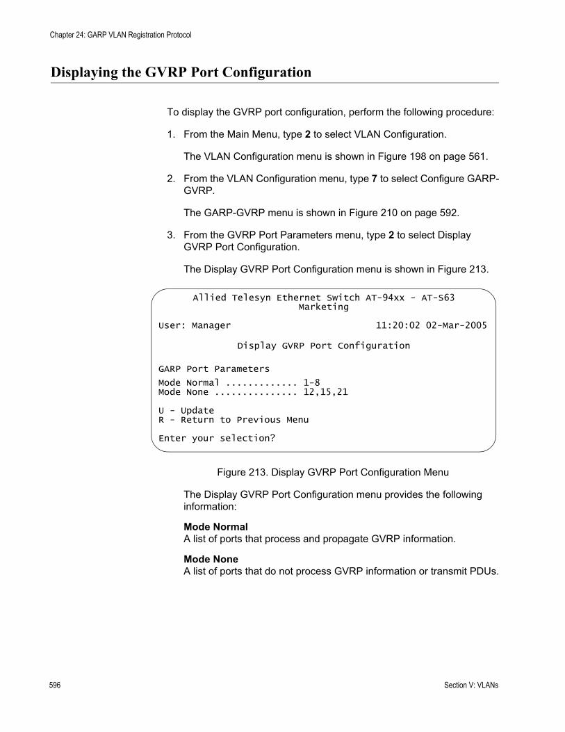
Chapter 24: GARP VLAN Registration Protocol
Displaying the GVRP Port Configuration
To display the GVRP port configuration, perform the following procedure:
1. From the Main Menu, type 2 to select VLAN Configuration.
The VLAN Configuration menu is shown in Figure 198 on page 561.
2. From the VLAN Configuration menu, type 7 to select Configure GARP-GVRP.
The GARP-GVRP menu is shown in Figure 210 on page 592.
3. From the GVRP Port Parameters menu, type 2 to select Display GVRP Port Configuration.
The Display GVRP Port Configuration menu is shown in Figure 213.
Figure 213. Display GVRP Port Configuration Menu
The Display GVRP Port Configuration menu provides the following information:
Mode NormalA list of ports that process and propagate GVRP information.
Mode NoneA list of ports that do not process GVRP information or transmit PDUs.
Allied Telesyn Ethernet Switch AT-94xx - AT-S63Marketing
User: Manager 11:20:02 02-Mar-2005
Display GVRP Port Configuration
GARP Port Parameters
Mode Normal ............. 1-8Mode None ............... 12,15,21
U - UpdateR - Return to Previous Menu
Enter your selection?
596 Section V: VLANs
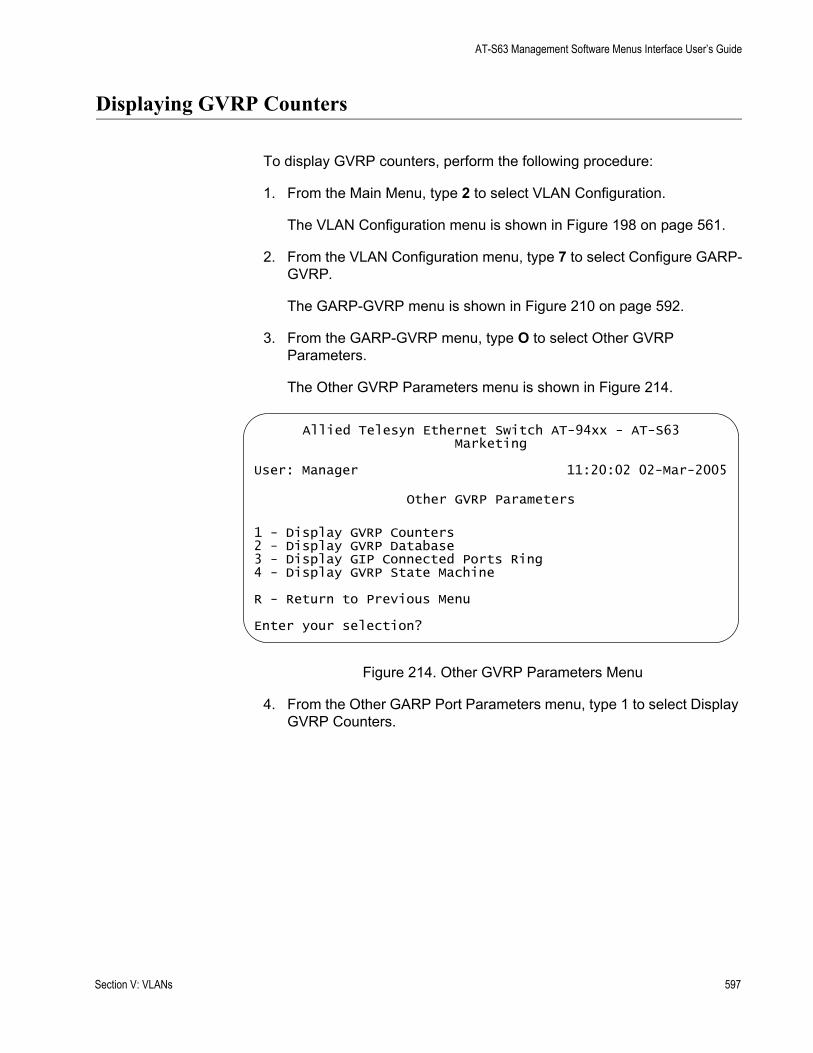
AT-S63 Management Software Menus Interface User’s Guide
Displaying GVRP Counters
To display GVRP counters, perform the following procedure:
1. From the Main Menu, type 2 to select VLAN Configuration.
The VLAN Configuration menu is shown in Figure 198 on page 561.
2. From the VLAN Configuration menu, type 7 to select Configure GARP-GVRP.
The GARP-GVRP menu is shown in Figure 210 on page 592.
3. From the GARP-GVRP menu, type O to select Other GVRP Parameters.
The Other GVRP Parameters menu is shown in Figure 214.
Figure 214. Other GVRP Parameters Menu
4. From the Other GARP Port Parameters menu, type 1 to select Display GVRP Counters.
Allied Telesyn Ethernet Switch AT-94xx - AT-S63Marketing
User: Manager 11:20:02 02-Mar-2005
Other GVRP Parameters
1 - Display GVRP Counters2 - Display GVRP Database3 - Display GIP Connected Ports Ring4 - Display GVRP State Machine
R - Return to Previous Menu
Enter your selection?
Section V: VLANs 597
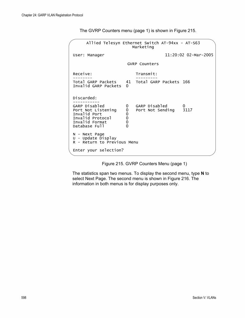
Chapter 24: GARP VLAN Registration Protocol
The GVRP Counters menu (page 1) is shown in Figure 215.
Figure 215. GVRP Counters Menu (page 1)
The statistics span two menus. To display the second menu, type N to select Next Page. The second menu is shown in Figure 216. The information in both menus is for display purposes only.
Allied Telesyn Ethernet Switch AT-94xx - AT-S63Marketing
User: Manager 11:20:02 02-Mar-2005
GVRP Counters
Receive: Transmit:-------- ---------Total GARP Packets 41 Total GARP Packets 166Invalid GARP Packets 0
Discarded:-----------GARP Disabled 0 GARP Disabled 0Port Not Listening 0 Port Not Sending 3117Invalid Port 0Invalid Protocol 0Invalid Format 0Database Full 0
N - Next PageU - Update DisplayR - Return to Previous Menu
Enter your selection?
598 Section V: VLANs
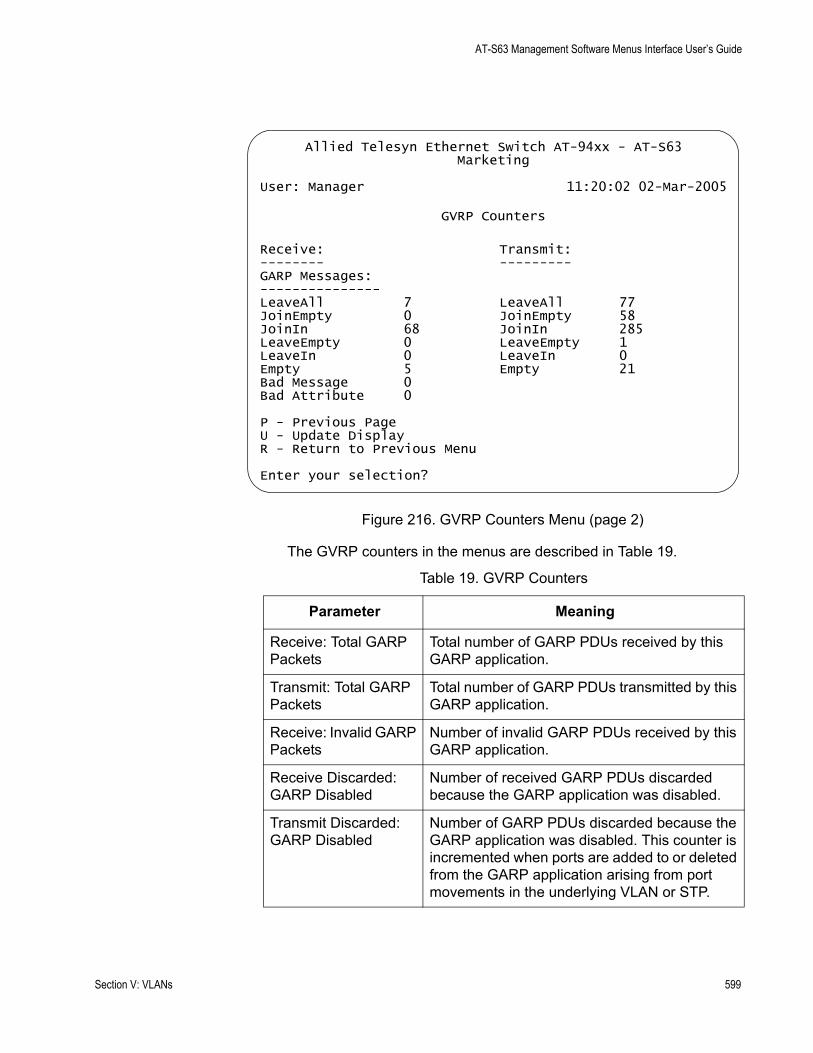
AT-S63 Management Software Menus Interface User’s Guide
Figure 216. GVRP Counters Menu (page 2)
The GVRP counters in the menus are described in Table 19.
Allied Telesyn Ethernet Switch AT-94xx - AT-S63Marketing
User: Manager 11:20:02 02-Mar-2005
GVRP Counters
Receive: Transmit:-------- ---------GARP Messages:---------------LeaveAll 7 LeaveAll 77JoinEmpty 0 JoinEmpty 58JoinIn 68 JoinIn 285LeaveEmpty 0 LeaveEmpty 1LeaveIn 0 LeaveIn 0Empty 5 Empty 21Bad Message 0Bad Attribute 0
P - Previous PageU - Update DisplayR - Return to Previous Menu
Enter your selection?
Table 19. GVRP Counters
Parameter Meaning
Receive: Total GARP Packets
Total number of GARP PDUs received by this GARP application.
Transmit: Total GARP Packets
Total number of GARP PDUs transmitted by this GARP application.
Receive: Invalid GARP Packets
Number of invalid GARP PDUs received by this GARP application.
Receive Discarded: GARP Disabled
Number of received GARP PDUs discarded because the GARP application was disabled.
Transmit Discarded: GARP Disabled
Number of GARP PDUs discarded because the GARP application was disabled. This counter is incremented when ports are added to or deleted from the GARP application arising from port movements in the underlying VLAN or STP.
Section V: VLANs 599
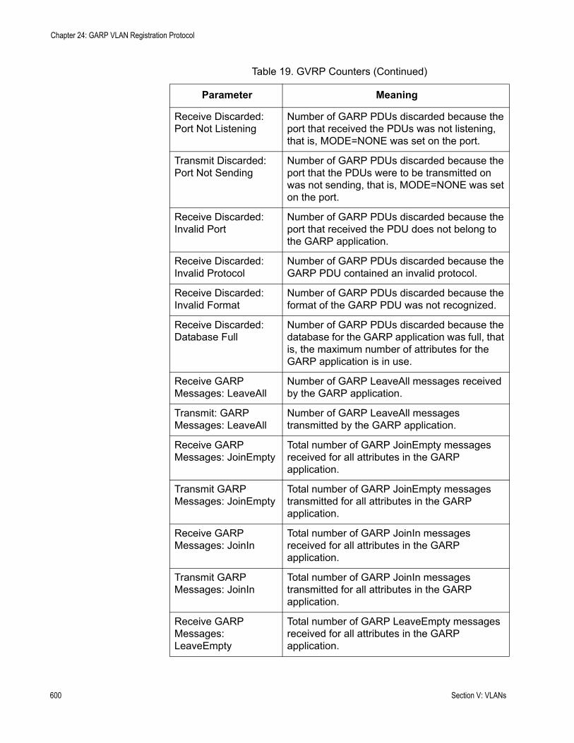
Chapter 24: GARP VLAN Registration Protocol
Receive Discarded: Port Not Listening
Number of GARP PDUs discarded because the port that received the PDUs was not listening, that is, MODE=NONE was set on the port.
Transmit Discarded: Port Not Sending
Number of GARP PDUs discarded because the port that the PDUs were to be transmitted on was not sending, that is, MODE=NONE was set on the port.
Receive Discarded: Invalid Port
Number of GARP PDUs discarded because the port that received the PDU does not belong to the GARP application.
Receive Discarded: Invalid Protocol
Number of GARP PDUs discarded because the GARP PDU contained an invalid protocol.
Receive Discarded: Invalid Format
Number of GARP PDUs discarded because the format of the GARP PDU was not recognized.
Receive Discarded: Database Full
Number of GARP PDUs discarded because the database for the GARP application was full, that is, the maximum number of attributes for the GARP application is in use.
Receive GARP Messages: LeaveAll
Number of GARP LeaveAll messages received by the GARP application.
Transmit: GARP Messages: LeaveAll
Number of GARP LeaveAll messages transmitted by the GARP application.
Receive GARP Messages: JoinEmpty
Total number of GARP JoinEmpty messages received for all attributes in the GARP application.
Transmit GARP Messages: JoinEmpty
Total number of GARP JoinEmpty messages transmitted for all attributes in the GARP application.
Receive GARP Messages: JoinIn
Total number of GARP JoinIn messages received for all attributes in the GARP application.
Transmit GARP Messages: JoinIn
Total number of GARP JoinIn messages transmitted for all attributes in the GARP application.
Receive GARP Messages: LeaveEmpty
Total number of GARP LeaveEmpty messages received for all attributes in the GARP application.
Table 19. GVRP Counters (Continued)
Parameter Meaning
600 Section V: VLANs

AT-S63 Management Software Menus Interface User’s Guide
Transmit GARP Messages: LeaveEmpty
Total number of GARP LeaveEmpty messages transmitted for all attributes in the GARP application.
Receive GARP Messages: LeaveIn
Total number of GARP LeaveIn messages received for all attributes in the GARP application.
Transmit GARP Messages: LeaveIn
Total number of GARP LeaveIn messages transmitted for all attributes in the GARP application.
Receive GARP Messages: Empty
Total number of GARP Empty messages received for all attributes in the GARP application.
Transmit GARP Messages: Empty
Total number of GARP Empty messages transmitted for all attributes in the GARP application.
Receive GARP Messages: Bad Message
Number of GARP messages that had an invalid Attribute Type value, an invalid Attribute Length value or an invalid Attribute Event value.
Receive GARP Messages: Bad Attribute
Number of GARP messages that had an invalid Attribute Value value.
Table 19. GVRP Counters (Continued)
Parameter Meaning
Section V: VLANs 601
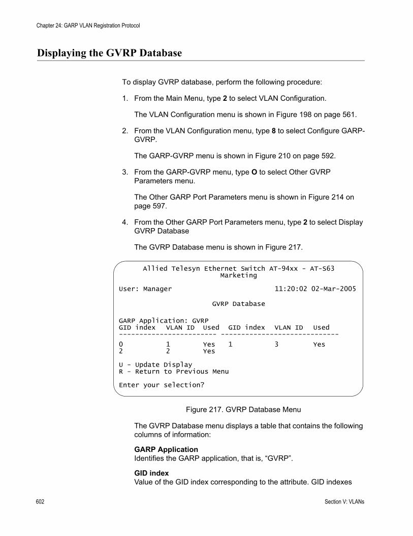
Chapter 24: GARP VLAN Registration Protocol
Displaying the GVRP Database
To display GVRP database, perform the following procedure:
1. From the Main Menu, type 2 to select VLAN Configuration.
The VLAN Configuration menu is shown in Figure 198 on page 561.
2. From the VLAN Configuration menu, type 8 to select Configure GARP-GVRP.
The GARP-GVRP menu is shown in Figure 210 on page 592.
3. From the GARP-GVRP menu, type O to select Other GVRP Parameters menu.
The Other GARP Port Parameters menu is shown in Figure 214 on page 597.
4. From the Other GARP Port Parameters menu, type 2 to select Display GVRP Database
The GVRP Database menu is shown in Figure 217.
Figure 217. GVRP Database Menu
The GVRP Database menu displays a table that contains the following columns of information:
GARP ApplicationIdentifies the GARP application, that is, “GVRP”.
GID indexValue of the GID index corresponding to the attribute. GID indexes
Allied Telesyn Ethernet Switch AT-94xx - AT-S63Marketing
User: Manager 11:20:02 02-Mar-2005
GVRP Database
GARP Application: GVRPGID index VLAN ID Used GID index VLAN ID Used------------------------ -----------------------------
0 1 Yes 1 3 Yes2 2 Yes
U - Update DisplayR - Return to Previous Menu
Enter your selection?
602 Section V: VLANs
AT-S63 Management Software Menus Interface User’s Guide
begin at 0. If the GARP application has no attributes presently registered, “No attributes have been registered” is displayed.
VLAN IDThe VLAN ID.
UsedIndicates whether the GID index is currently being used by any port in the GARP application. The definition of “used” is whether the Applicant and Registrar state machine for the GID index are in a non-initialized state, that is, not in {Vo, Mt} state. The value of this parameter is either “Yes” or “No”.
Section V: VLANs 603
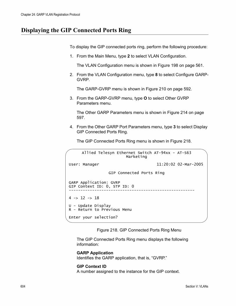
Chapter 24: GARP VLAN Registration Protocol
Displaying the GIP Connected Ports Ring
To display the GIP connected ports ring, perform the following procedure:
1. From the Main Menu, type 2 to select VLAN Configuration.
The VLAN Configuration menu is shown in Figure 198 on page 561.
2. From the VLAN Configuration menu, type 8 to select Configure GARP-GVRP.
The GARP-GVRP menu is shown in Figure 210 on page 592.
3. From the GARP-GVRP menu, type O to select Other GVRP Parameters menu.
The Other GARP Parameters menu is shown in Figure 214 on page 597.
4. From the Other GARP Port Parameters menu, type 3 to select Display GIP Connected Ports Ring.
The GIP Connected Ports Ring menu is shown in Figure 218.
Figure 218. GIP Connected Ports Ring Menu
The GIP Connected Ports Ring menu displays the following information:
GARP ApplicationIdentifies the GARP application, that is, “GVRP.”
GIP Context IDA number assigned to the instance for the GIP context.
Allied Telesyn Ethernet Switch AT-94xx - AT-S63Marketing
User: Manager 11:20:02 02-Mar-2005
GIP Connected Ports Ring
GARP Application: GVRPGIP Context ID: 0, STP ID: 0------------------------------------------------------
4 -> 12 -> 18
U - Update DisplayR - Return to Previous Menu
Enter your selection?
604 Section V: VLANs

AT-S63 Management Software Menus Interface User’s Guide
STP IDPresent if the GARP application is GVRP; identifies the spanning tree instance associated with the GIP context.
Connected RingThe ring of connected ports. Only ports presently in the spanning tree Forwarding state are eligible for membership in the GIP connected ring. If no ports exist in the GIP connected ring, “No ports are connected” is displayed. If the GARP application has no ports, “No ports have been assigned” is displayed.
Section V: VLANs 605
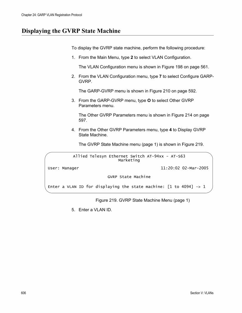
Chapter 24: GARP VLAN Registration Protocol
Displaying the GVRP State Machine
To display the GVRP state machine, perform the following procedure:
1. From the Main Menu, type 2 to select VLAN Configuration.
The VLAN Configuration menu is shown in Figure 198 on page 561.
2. From the VLAN Configuration menu, type 7 to select Configure GARP-GVRP.
The GARP-GVRP menu is shown in Figure 210 on page 592.
3. From the GARP-GVRP menu, type O to select Other GVRP Parameters menu.
The Other GVRP Parameters menu is shown in Figure 214 on page 597.
4. From the Other GVRP Parameters menu, type 4 to Display GVRP State Machine.
The GVRP State Machine menu (page 1) is shown in Figure 219.
Figure 219. GVRP State Machine Menu (page 1)
5. Enter a VLAN ID.
Allied Telesyn Ethernet Switch AT-94xx - AT-S63Marketing
User: Manager 11:20:02 02-Mar-2005
GVRP State Machine
Enter a VLAN ID for displaying the state machine: [1 to 4094] -> 1
606 Section V: VLANs
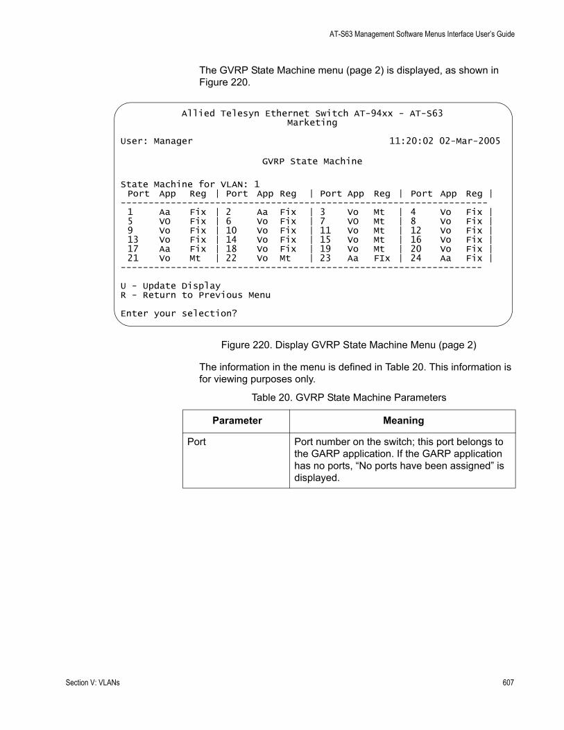
AT-S63 Management Software Menus Interface User’s Guide
The GVRP State Machine menu (page 2) is displayed, as shown in Figure 220.
Figure 220. Display GVRP State Machine Menu (page 2)
The information in the menu is defined in Table 20. This information is for viewing purposes only.
Allied Telesyn Ethernet Switch AT-94xx - AT-S63Marketing
User: Manager 11:20:02 02-Mar-2005
GVRP State Machine
State Machine for VLAN: 1Port App Reg | Port App Reg | Port App Reg | Port App Reg |
------------------------------------------------------------------1 Aa Fix | 2 Aa Fix | 3 Vo Mt | 4 Vo Fix |5 VO Fix | 6 Vo Fix | 7 VO Mt | 8 Vo Fix |9 Vo Fix | 10 Vo Fix | 11 Vo Mt | 12 Vo Fix |13 Vo Fix | 14 Vo Fix | 15 Vo Mt | 16 Vo Fix |17 Aa Fix | 18 Vo Fix | 19 Vo Mt | 20 Vo Fix |21 Vo Mt | 22 Vo Mt | 23 Aa FIx | 24 Aa Fix |
-----------------------------------------------------------------
U - Update DisplayR - Return to Previous Menu
Enter your selection?
Table 20. GVRP State Machine Parameters
Parameter Meaning
Port Port number on the switch; this port belongs to the GARP application. If the GARP application has no ports, “No ports have been assigned” is displayed.
Section V: VLANs 607
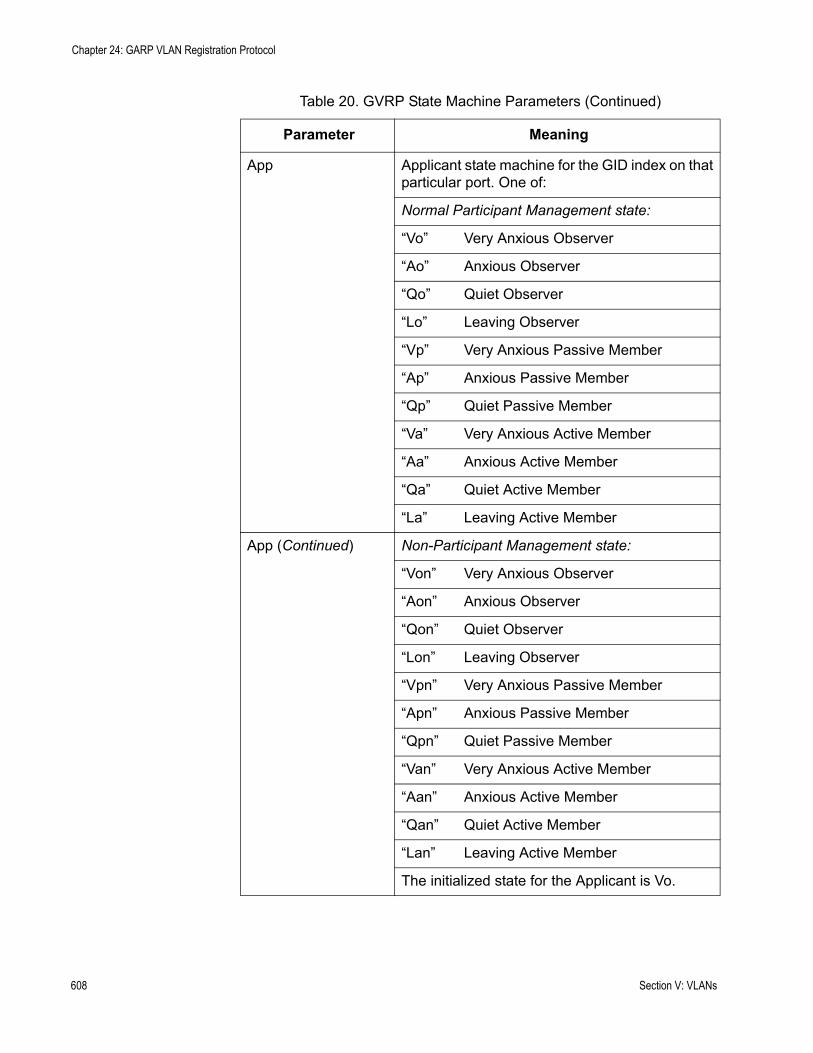
Chapter 24: GARP VLAN Registration Protocol
App Applicant state machine for the GID index on that particular port. One of:
Normal Participant Management state:
“Vo” Very Anxious Observer
“Ao” Anxious Observer
“Qo” Quiet Observer
“Lo” Leaving Observer
“Vp” Very Anxious Passive Member
“Ap” Anxious Passive Member
“Qp” Quiet Passive Member
“Va” Very Anxious Active Member
“Aa” Anxious Active Member
“Qa” Quiet Active Member
“La” Leaving Active Member
App (Continued) Non-Participant Management state:
“Von” Very Anxious Observer
“Aon” Anxious Observer
“Qon” Quiet Observer
“Lon” Leaving Observer
“Vpn” Very Anxious Passive Member
“Apn” Anxious Passive Member
“Qpn” Quiet Passive Member
“Van” Very Anxious Active Member
“Aan” Anxious Active Member
“Qan” Quiet Active Member
“Lan” Leaving Active Member
The initialized state for the Applicant is Vo.
Table 20. GVRP State Machine Parameters (Continued)
Parameter Meaning
608 Section V: VLANs
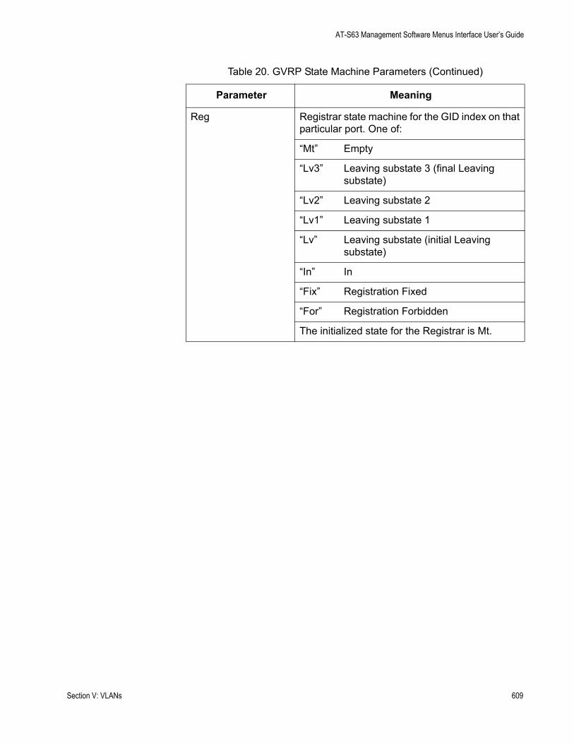
AT-S63 Management Software Menus Interface User’s Guide
Reg Registrar state machine for the GID index on that particular port. One of:
“Mt” Empty
“Lv3” Leaving substate 3 (final Leaving substate)
“Lv2” Leaving substate 2
“Lv1” Leaving substate 1
“Lv” Leaving substate (initial Leaving substate)
“In” In
“Fix” Registration Fixed
“For” Registration Forbidden
The initialized state for the Registrar is Mt.
Table 20. GVRP State Machine Parameters (Continued)
Parameter Meaning
Section V: VLANs 609

Chapter 24: GARP VLAN Registration Protocol
610 Section V: VLANs

Chapter 25
Multiple VLANs
This chapter describes the multiple VLAN modes and how to select a mode.
This chapter contains the following sections:
“Multiple VLAN Mode Overview” on page 612“Selecting a VLAN Mode” on page 616“Displaying VLAN Information” on page 617
Section V: VLANs 611
Chapter 25: Multiple VLANs
Multiple VLAN Mode Overview
The multiple VLAN modes are designed to simplify the task of configuring the switch in network environments that require a high degree of network segmentation. In a multiple VLAN mode, the ports on a switch are prohibited from forwarding traffic to each other and are only allowed to forward traffic to a user-designated uplink port. These configurations isolate the traffic on each port from all other ports, while providing access to the uplink port.
The AT-S63 management software supports two types of multiple VLAN modes:
802.1Q-compliant Multiple VLAN mode Multiple VLAN mode (also referred to as non-802.1Q compliant Multiple VLAN mode)
Each mode uses a different technique to isolate the ports and their traffic. The first method uses VLANs while the second uses port mapping. The uplink port is also different in each mode. In one the port is a tagged port and in the other untagged. This is explained in the following subsections.
NoteThe multiple VLAN mode feature is supported only in single switch (i.e. edge switch) environments. This means that cascading of switches while in Multiple VLANs mode is not allowed.
Configuring multiple VLANs on a cascaded switch can possibly result in disconnection of network paths between switches unless the port used to link the switch (being configured for multiple VLANs mode) is configured as uplink VLAN port.
Configuring multiple VLANs on cascaded switches can also affect enhanced stacking because the master switch may not be able to detect member switches beyond the first cascaded switch.
802.1Q-Compliant
Multiple VLANMode
In this mode, each port is placed into a separate VLAN as an untagged port. The VLAN names and VID numbers are based on the port numbers. For example, the VLAN for port 4 is named Client_VLAN_4 and is given the VID of 4, the VLAN for port 5 is named Client_VLAN_5 and has a VID of 5, and so on.
The VLAN configuration is accomplished automatically by the switch. After you select the mode and an uplink port, the switch forms the VLANs. It also assigns the PVID values as well. For example, the PVID for port 4 is assigned as 4, to match the VID of 4.
612 Section V: VLANs
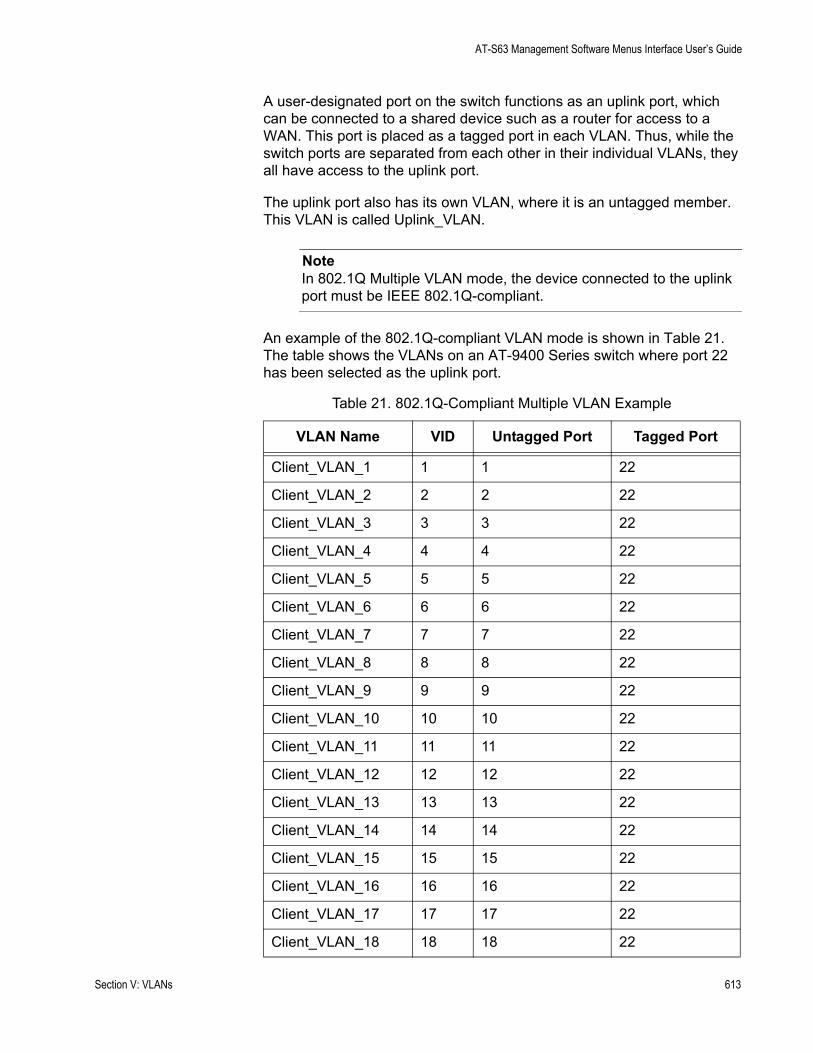
AT-S63 Management Software Menus Interface User’s Guide
A user-designated port on the switch functions as an uplink port, which can be connected to a shared device such as a router for access to a WAN. This port is placed as a tagged port in each VLAN. Thus, while the switch ports are separated from each other in their individual VLANs, they all have access to the uplink port.
The uplink port also has its own VLAN, where it is an untagged member. This VLAN is called Uplink_VLAN.
NoteIn 802.1Q Multiple VLAN mode, the device connected to the uplink port must be IEEE 802.1Q-compliant.
An example of the 802.1Q-compliant VLAN mode is shown in Table 21. The table shows the VLANs on an AT-9400 Series switch where port 22 has been selected as the uplink port.
Table 21. 802.1Q-Compliant Multiple VLAN Example
VLAN Name VID Untagged Port Tagged Port
Client_VLAN_1 1 1 22
Client_VLAN_2 2 2 22
Client_VLAN_3 3 3 22
Client_VLAN_4 4 4 22
Client_VLAN_5 5 5 22
Client_VLAN_6 6 6 22
Client_VLAN_7 7 7 22
Client_VLAN_8 8 8 22
Client_VLAN_9 9 9 22
Client_VLAN_10 10 10 22
Client_VLAN_11 11 11 22
Client_VLAN_12 12 12 22
Client_VLAN_13 13 13 22
Client_VLAN_14 14 14 22
Client_VLAN_15 15 15 22
Client_VLAN_16 16 16 22
Client_VLAN_17 17 17 22
Client_VLAN_18 18 18 22
Section V: VLANs 613

Chapter 25: Multiple VLANs
This highly segmented configuration is useful in situations where traffic generated by each end node or network segment connected to a port on the switch needs to be kept separate from all other network traffic, while still allowing access to an uplink to a WAN. Unicast traffic received by the uplink port is effectively directed to the appropriate port and end node and is not directed to any other port on the switch.
The 802.1Q Multiple VLAN configuration is appropriate when the device connected to the uplink port is IEEE 802.1Q compatible, meaning that it can handle tagged packets.
When you select the 802.1Q-compliant VLAN mode, you are asked to specify the uplink VLAN port. You can specify only one uplink port. The switch automatically configures the ports into the separate VLANs.
NoteThe uplink VLAN is the management VLAN. Any remote management of the switch must be made through the uplink VLAN.
Non-802.1QCompliant
Multiple VLANMode
Unlike the 802.1Q-compliant VLAN mode, which isolates port traffic by placing each port in a separate VLAN, this mode forms one VLAN with a VID of 1 that encompasses all ports. To establish traffic isolation, it uses port mapping. The result, however, is the same. Ports are permitted to forward traffic only to the designated uplink port and to no other port, even when they receive a broadcast packet.
Another difference with this mode is that the uplink port is untagged. Consequently, you would use this mode when the device connected to the uplink port is not IEEE 802.1Q compatible, meaning that the device cannot handle tagged packets.
Client_VLAN_19 19 19 22
Client_VLAN_20 20 20 22
Client_VLAN_21 21 21 22
Uplink_VLAN 22 22
Client_VLAN_23 23 23 22
Client_VLAN_24 24 24 22
Table 21. 802.1Q-Compliant Multiple VLAN Example (Continued)
VLAN Name VID Untagged Port Tagged Port
614 Section V: VLANs

AT-S63 Management Software Menus Interface User’s Guide
NoteWhen the uplink port receives a packet with a destination MAC address that is not in the MAC address table, the port broadcasts the packet to all switch ports. This can result in ports receiving packets that are not intended for them.
Also note that a switch operating in this mode can be remotely managed through any port on the switch, not just the uplink port.
Section V: VLANs 615
Chapter 25: Multiple VLANs
Selecting a VLAN Mode
The following procedure explains how to select a VLAN mode. Available modes are:
User-configured VLAN mode (port-based and tagged VLANs)IEEE 802.1Q Compliant Multiple VLAN modeNon-IEEE 802.1Q Compliant Multiple VLAN mode
NoteAny port-based or tagged VLANs you created are not retained when you change the VLAN mode from the user-configured mode to a multiple VLAN mode and, at some point, reset the switch. The user- configured VLAN information is lost and must be recreated if you later return the switch to the user-configured VLAN mode.
To select a VLAN mode, perform the following procedure:
1. From the Main Menu, type 2 to select VLAN Configuration.
The VLAN Configuration menu is shown in Figure 198 on page 561.
2. From the VLAN Configuration menu, type 2 to select VLANs Mode.
The following prompt is displayed:
Enter VLAN Mode (U-UserConfig, M-Multiple, Q-802.1Q Multiple VLANs) ->
3. Type Q to activate 802.1Q Multiple VLAN mode, M for Non-802.1Q compliant multiple VLAN mode, or U to create your own port-based and tagged VLANs. User-configured is the default setting.
If you enter Q or M, the following prompt is displayed:
Enter Uplink VLAN Port number -> [1 to 24] ->
4. Enter the port number on the switch that will function as the uplink port for the other ports. You can specify only one port.
The following prompt is displayed:
SUCCESSPress any key to continue ...
The new VLAN mode is now active on the switch.
5. After making changes, type R until you return to the Main Menu. Then type S to select Save Configuration Changes.
616 Section V: VLANs
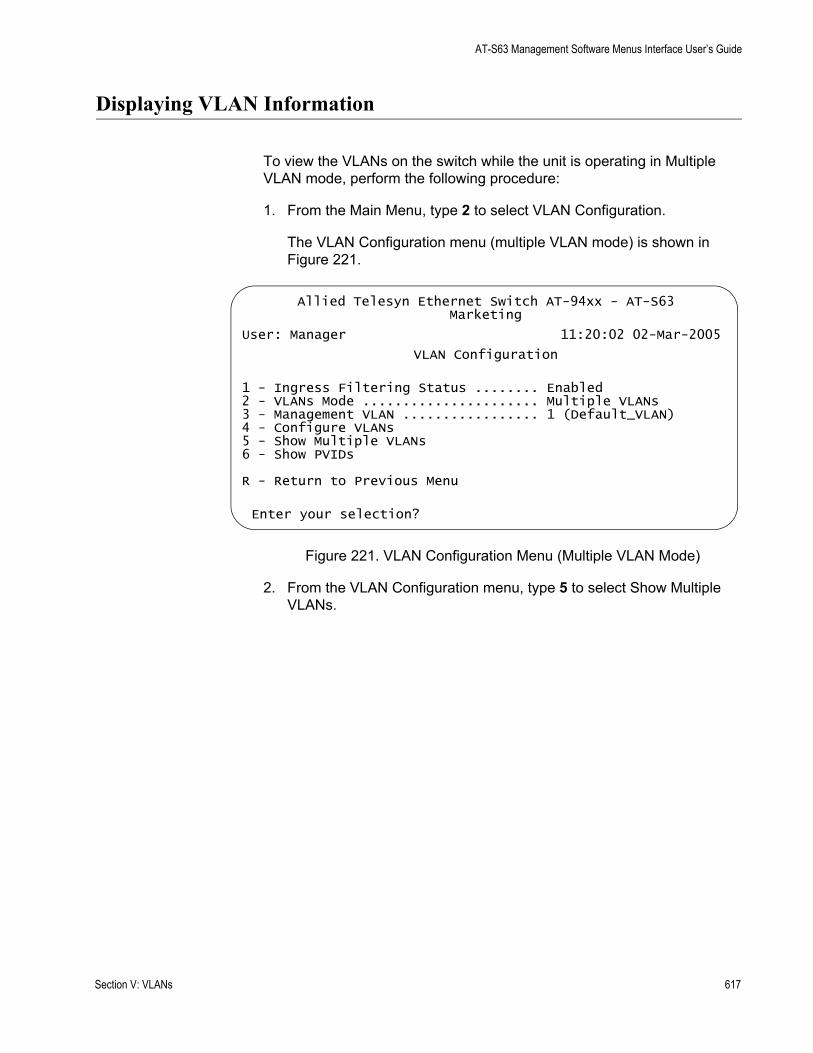
AT-S63 Management Software Menus Interface User’s Guide
Displaying VLAN Information
To view the VLANs on the switch while the unit is operating in Multiple VLAN mode, perform the following procedure:
1. From the Main Menu, type 2 to select VLAN Configuration.
The VLAN Configuration menu (multiple VLAN mode) is shown in Figure 221.
Figure 221. VLAN Configuration Menu (Multiple VLAN Mode)
2. From the VLAN Configuration menu, type 5 to select Show Multiple VLANs.
Allied Telesyn Ethernet Switch AT-94xx - AT-S63Marketing
User: Manager 11:20:02 02-Mar-2005
VLAN Configuration
1 - Ingress Filtering Status ........ Enabled2 - VLANs Mode ...................... Multiple VLANs3 - Management VLAN ................. 1 (Default_VLAN)4 - Configure VLANs5 - Show Multiple VLANs6 - Show PVIDs
R - Return to Previous Menu
Enter your selection?
Section V: VLANs 617

Chapter 25: Multiple VLANs
The Show Multiple VLANs menu is shown in Figure 222.
Figure 222. Show VLANs Menu, Multiple VLANS
The Show Multiple VLANs menu displays a table that contains the following columns of information:
Name Name of the VLAN.
Untagged PortThe untagged ports that are part of the VLAN.
Uplink PortThe uplink port for the VLAN.
VLAN IDThe VLAN ID.
Allied Telesyn Ethernet Switch AT-94xx - AT-S63Marketing
User: Manager 11:20:02 02-Mar-2005
Show Multiple VLANs
Name Untagged Port Uplink Port VLAN ID----------------------------------------------------Client_1 1 24 1Client_2 1 24 1Client_3 1 24 1Client_4 1 24 1Client_5 1 24 1Client_6 1 24 1Client_7 1 24 1Client_8 1 24 1
N - Next PageU - Update DisplayR - Return to Previous Menu
Enter your selection?
618 Section V: VLANs
Chapter 26
Protected Ports VLANs
This chapter explains protected ports VLANs. It contains the following sections:
“Protected Ports VLAN Overview” on page 620“Creating a Protected Ports VLAN” on page 623“Modifying a Protected Ports VLAN” on page 626“Displaying a Protected Ports VLAN” on page 630“Deleting a Protected Ports VLAN” on page 632
Section V: VLANs 619

Chapter 26: Protected Ports VLANs
Protected Ports VLAN Overview
The purpose of a protected ports VLAN is to allow multiple ports on the switch to share the same uplink port but not share traffic with each other.
This feature has some of the same characteristics as the multiple VLAN modes described in the previous chapter. In a protected ports VLAN, each port is considered a separate LAN segment that can only communicate with an uplink port. The result is a configuration appropriate in network environments that require a great deal of segmentation.
One of the advantages of a protected ports VLAN is that it offers more flexibility. With the multiple VLAN modes, you can select only one uplink port which is shared by all the other ports. Also, you are not allowed to modify the configuration.
With protected ports VLANs, you can create LAN segments that consist of more than one port and you can specify multiple uplink ports.
Another advantage is that the switch can support protected ports VLANs as well as port-based and tagged VLANs simultaneously, something that is not allowed with the multiple VLAN modes.
An important concept of this feature is groups. A group is a selection of one or more ports that function as a LAN segment within the VLAN. The ports in each group are independent of the ports in the other groups of the VLAN. The ports of a group can share traffic only amongst themselves and with the uplink port, but not with ports in other groups of the VLAN.
A protected ports VLAN can consist of two or more groups and a group can consist of one or more ports. The ports of a group can be either tagged or untagged.
This type of VLAN also shares some common features with tagged VLANs, where one or more ports are shared by different LAN segments. But there are significant differences. First, all the ports in a tagged VLAN are considered a LAN segment, while the ports in a protected ports VLAN, though residing within a single VLAN, are subdivided into the smaller unit of groups, which represent the LAN segments.
Second, a tagged VLAN, by its nature, contains one or more tagged ports. These are the ports that are shared among one or more tagged VLANs. The device connected to a tagged port must be 802.1Q compliant and it must be able to handle tagged packets.
In contrast, the uplink port in a protected ports VLAN, which is shared by the ports in the different groups, can be either tagged or untagged. The device connected to it does not necessarily need to be 802.1Q compliant.
620 Section V: VLANs
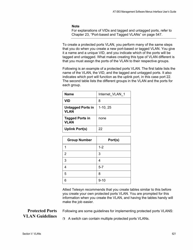
AT-S63 Management Software Menus Interface User’s Guide
NoteFor explanations of VIDs and tagged and untagged ports, refer to Chapter 23, “Port-based and Tagged VLANs” on page 547.
To create a protected ports VLAN, you perform many of the same steps that you do when you create a new port-based or tagged VLAN. You give it a name and a unique VID, and you indicate which of the ports will be tagged and untagged. What makes creating this type of VLAN different is that you must assign the ports of the VLAN to their respective groups.
Following is an example of a protected ports VLAN. The first table lists the name of the VLAN, the VID, and the tagged and untagged ports. It also indicates which port will function as the uplink port, in this case port 22. The second table lists the different groups in the VLAN and the ports for each group.
Allied Telesyn recommends that you create tables similar to this before you create your own protected ports VLAN. You are prompted for this information when you create the VLAN, and having the tables handy will make the job easier.
Protected PortsVLAN Guidelines
Following are some guidelines for implementing protected ports VLANS:
A switch can contain multiple protected ports VLANs.
Name Internet_VLAN_1
VID 8
Untagged Ports in VLAN
1-10, 25
Tagged Ports in VLAN
none
Uplink Port(s) 22
Group Number Port(s)
1 1-2
2 3
3 4
4 5-7
5 8
6 9-10
Section V: VLANs 621

Chapter 26: Protected Ports VLANs
A protected ports VLAN should contain a minimum of two groups. A protected ports VLAN of only one group has little value. Create a port-based or tagged VLAN instead.A protected ports VLAN can contain any number of groups.A group can contain any number of ports.The ports of a group can be tagged or untagged.Each group must be assigned a unique group number on the switch. The number can be from 1 to 256.A protected ports VLAN can contain more than one uplink port.An uplink port can be either tagged or untagged.Uplink ports can be shared among more than one protected ports VLAN, but only if they are tagged.A switch can contain a combination of port-based and tagged VLANs and protected ports VLANs.A port that is a member of a group in a protected ports VLAN cannot be a member of a port-based or tagged VLAN.A group can be a member of more than one protected ports VLAN at a time. However, the port members of the group must be identical in both VLANs and the ports must be tagged.You cannot create protected ports VLANs when the switch is operating in a multiple VLAN mode.A port that is already an untagged member of a protected ports VLAN cannot be made an untagged member of another VLAN until it is first removed from its current VLAN assignment and returned to the Default_VLAN.
622 Section V: VLANs

AT-S63 Management Software Menus Interface User’s Guide
Creating a Protected Ports VLAN
To create a new protected ports VLAN, perform the following procedure:
1. From the Main Menu, type 2 to select VLAN Configuration.
2. From the VLAN Configuration menu, type 4 to select Configure VLANs.
NoteIf the menu does not include selection 4, Configure VLANs, the switch is running a multiple VLAN mode. To change the switch’s VLAN mode, refer to “Selecting a VLAN Mode” on page 616.
3. From the Configure VLANs menu, type 1 to select Create VLAN.
The Create VLAN menu is shown in Figure 223.
Figure 223. Create VLAN Menu
4. Type 1 to select VLAN Name.
The following prompt is displayed:
Enter new value ->
5. Type a name for the new protected ports VLAN.
The name can be from one to fifteen alphanumeric characters in length. The name should reflect the function of the nodes that will be a part of the protected ports VLAN (for example, InternetGroups). The name cannot contain spaces or special characters, such as asterisks (*) or exclamation points (!).
Allied Telesyn Ethernet Switch AT-94xx - AT-S63Marketing
User: Manager 11:20:02 02-Mar-2005
Create VLAN
1 - VLAN Name ............2 - VLAN ID (VID) ........ 23 - Tagged Ports .........4 - Untagged Ports .......5 - Protected Ports ...... No
C - Create VLANR - Return to Previous Menu
Enter your selection?
Section V: VLANs 623

Chapter 26: Protected Ports VLANs
NoteA VLAN must be assigned a name.
6. Type 2 to select VLAN ID (VID.
The following prompt is displayed:
Enter new value -> [2 to 4094] ->
7. Type a VID value for the new VLAN. The range for the VID value is 1 to 4094.
The AT-S63 management software uses the next available VID number on the switch as the default value. It is important to note that the switch is only aware of the VIDs of the VLANs that exist on the device, and not those that might already be in use in the network. For example, if you add a new AT-9400 Series switch to a network that already contains VLANs that use VIDs 2 through 24, the AT-S63 management software still uses VID 2 as the default value when you create the first VLAN on the new switch, even though that VID number is already being used by another VLAN on the network. To prevent inadvertently using the same VID for two different VLANs, you should keep a list of all your network VLANs and their VID values.
NoteA VLAN must have a VID.
8. If the VLAN will contain tagged ports, type 3 to select Tagged Ports and specify the ports. If this VLAN will not contain any tagged ports, leave this field empty.
You can specify the ports individually (e.g., 2,3,5), as a range (e.g., 7-9), or both (e.g., 2,5,7-9).
9. Type 4 to select Untagged Ports and specify the ports on the switch to function as untagged ports in the VLAN. If this VLAN will not contain any untagged ports, leave this field empty.
You can specify the ports individually (e.g., 2,3,5), as a range (e.g., 7-9), or both (e.g., 2,5,7-9).
10. Type 5 to select Protected Ports.
The following prompt is displayed:
Enter New Value [Yes/No] ->
11. To make this a protected ports VLAN, type Y. If you do not want this to be a protected ports VLAN and want it to be a port-based or tagged VLAN, type N.
624 Section V: VLANs

AT-S63 Management Software Menus Interface User’s Guide
12. Type C to select Create VLAN.
The following prompt is displayed:
Enter Uplink Ports (4 - 12) ->
The prompt will shown the ports that you specified as belonging to the VLAN.
13. Enter the port in the VLAN that will function as the uplink port for the different VLAN groups. You can select more than one uplink port.
The following prompt is displayed:
Enter Group Ports (4 - 11) ->
The prompt lists the ports in the VLAN, minus the uplink port you specified in the previous step.
14. Specify the ports of one of the groups of the protected ports VLAN. This can be a few as one port or as many as all the remaining ports of the VLAN. You can specify the ports of the group individually (e.g., 2,3,5), as a range (e.g., 7-9), or both (e.g., 2,5,7-9).
The following prompt is displayed:
Enter Group Number ->
15. Enter a group number for the port(s). Each group on the switch must be have a unique group number. The range is 1 to 256.
16. If there are ports within the VLAN that still need to be assigned to a group, the prompt in Step 13 is displayed again, showing the unassigned ports. You must repeat Steps 14 and 15, creating additional groups, until all of the ports in the VLAN have been assigned to a group.
After you create all of the groups, the following prompt is displayed:
SUCCESS - Press any key to continue.Press any key to continue.
The new protected ports VLAN and its groups are now active on the switch.
17. Press any key to return to the Configure VLANs menu.
18. After making changes, type R until you return to the Main Menu. Then type S to select Save Configuration Changes.
Section V: VLANs 625
Chapter 26: Protected Ports VLANs
Modifying a Protected Ports VLAN
Please note the following before you perform this procedure:
To modify this type of VLAN, you must recreate it by reselecting the uplink port(s) and reassigning the ports to the groups. For this reason Allied Telesyn recommends that before you perform this procedure you first display the details of the protected ports VLAN you want to modify and write down on paper the VLAN’s current configuration (i.e., uplink port and port to group assignments). This provides information that allows you to recreate the current configuration, with whatever modifications you want to make, when you perform the procedure. To display a VLAN’s configuration, refer to “Displaying a Protected Ports VLAN” on page 630.If you are adding untagged ports, the ports must be untagged members of the Default_VLAN or a port-based or tagged VLAN. They cannot be members of another protected ports VLAN.An untagged port removed from a VLAN is automatically returned to the Default_VLAN.A port that is already an untagged member of a protected ports VLAN cannot be made an untagged member of another VLAN until it is first removed from its current VLAN assignment and returned to the Default_VLAN.
NoteTo modify a VLAN, you need to know its VID. To view VLAN VIDs, refer to “Displaying a Protected Ports VLAN” on page 630.
To modify a protected ports VLAN, perform the following procedure:
1. From the Main Menu, type 2 to select VLAN Configuration.
The VLAN Configuration menu is shown in Figure 198 on page 561.
2. From the VLAN Configuration menu, type 4 to select Configure VLANs.
The Configure VLANs menu is shown in Figure 199 on page 562.
NoteIf selection 4, Configure VLANs, is not displayed in the menu, the switch is running a multiple VLAN mode. To change a switch’s VLAN mode, refer to “Selecting a VLAN Mode” on page 616.
3. From the Configure VLANs menu, type 2 to select Modify VLAN.
626 Section V: VLANs
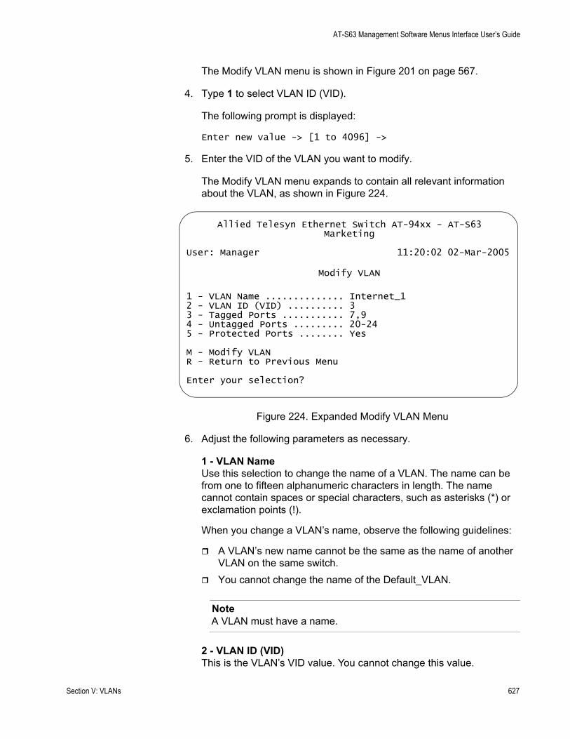
AT-S63 Management Software Menus Interface User’s Guide
The Modify VLAN menu is shown in Figure 201 on page 567.
4. Type 1 to select VLAN ID (VID).
The following prompt is displayed:
Enter new value -> [1 to 4096] ->
5. Enter the VID of the VLAN you want to modify.
The Modify VLAN menu expands to contain all relevant information about the VLAN, as shown in Figure 224.
Figure 224. Expanded Modify VLAN Menu
6. Adjust the following parameters as necessary.
1 - VLAN NameUse this selection to change the name of a VLAN. The name can be from one to fifteen alphanumeric characters in length. The name cannot contain spaces or special characters, such as asterisks (*) or exclamation points (!).
When you change a VLAN’s name, observe the following guidelines:
A VLAN’s new name cannot be the same as the name of another VLAN on the same switch. You cannot change the name of the Default_VLAN.
NoteA VLAN must have a name.
2 - VLAN ID (VID)This is the VLAN’s VID value. You cannot change this value.
Allied Telesyn Ethernet Switch AT-94xx - AT-S63Marketing
User: Manager 11:20:02 02-Mar-2005
Modify VLAN
1 - VLAN Name .............. Internet_12 - VLAN ID (VID) .......... 33 - Tagged Ports ........... 7,94 - Untagged Ports ......... 20-245 - Protected Ports ........ Yes
M - Modify VLANR - Return to Previous Menu
Enter your selection?
Section V: VLANs 627
Chapter 26: Protected Ports VLANs
3 - Tagged PortsUse this selection to add or remove tagged ports from the VLAN. You can specify the ports individually (e.g., 2,3,5), as a range (e.g., 7-9), or both (e.g., 2,5,7-9). The new list of tagged ports will replace the existing tagged ports.
4 - Untagged PortsUse this selection to add or remove untagged ports from the VLAN. You can specify the ports individually (e.g., 2,3,5), as a range (e.g., 7-9), or both (e.g., 2,5,7-9). The new list of untagged ports will replace the existing list of untagged ports.
5 - Protected PortsThis option cannot be changed. To convert a protected ports VLAN into a tagged or port-based VLAN, you must first delete it and then recreate it as a tagged or port-based VLAN.
7. After making the desired changes, type M to select Modify VLAN.
The following prompt is displayed:
Enter Uplink Ports (4 - 12) ->
This prompt will differ depending on the ports you specified as part of the protected ports VLAN.
8. Enter the port in the VLAN that will function as the uplink port for the different VLAN groups. You can select more than one uplink port.
The following prompt is displayed:
Enter Group Ports (4 - 11) ->
The prompt now lists the ports in the VLAN, minus the uplink port you specified in the previous step.
9. Specify the ports of one of the groups of the protected ports VLAN. This can be a small as one port or as many as all the remaining ports of the VLAN. You can specify the ports of the group individually (e.g., 2,3,5), as a range (e.g., 7-9), or both (e.g., 2,5,7-9).
The following prompt is displayed:
Enter Group Number ->
10. Enter a group number for the port(s). Each group on the switch must be given a unique group number.
11. If there are ports within the VLAN that still need to be assigned to a group, the prompt in Step 8 is displayed again, showing the unassigned ports. You must repeat Steps 9 and 10, creating additional groups, until all of the ports in the VLAN have been assigned to a group.
628 Section V: VLANs

AT-S63 Management Software Menus Interface User’s Guide
After you have created all of the groups, this prompt is displayed:
SUCCESS - Press any key to continue.Press any key to continue.
The modified protected ports VLAN and its groups are now active on the switch.
12. Press any key to return to the Configure VLANs menu.
13. After making changes, type R until you return to the Main Menu. Then type S to select Save Configuration Changes.
Section V: VLANs 629
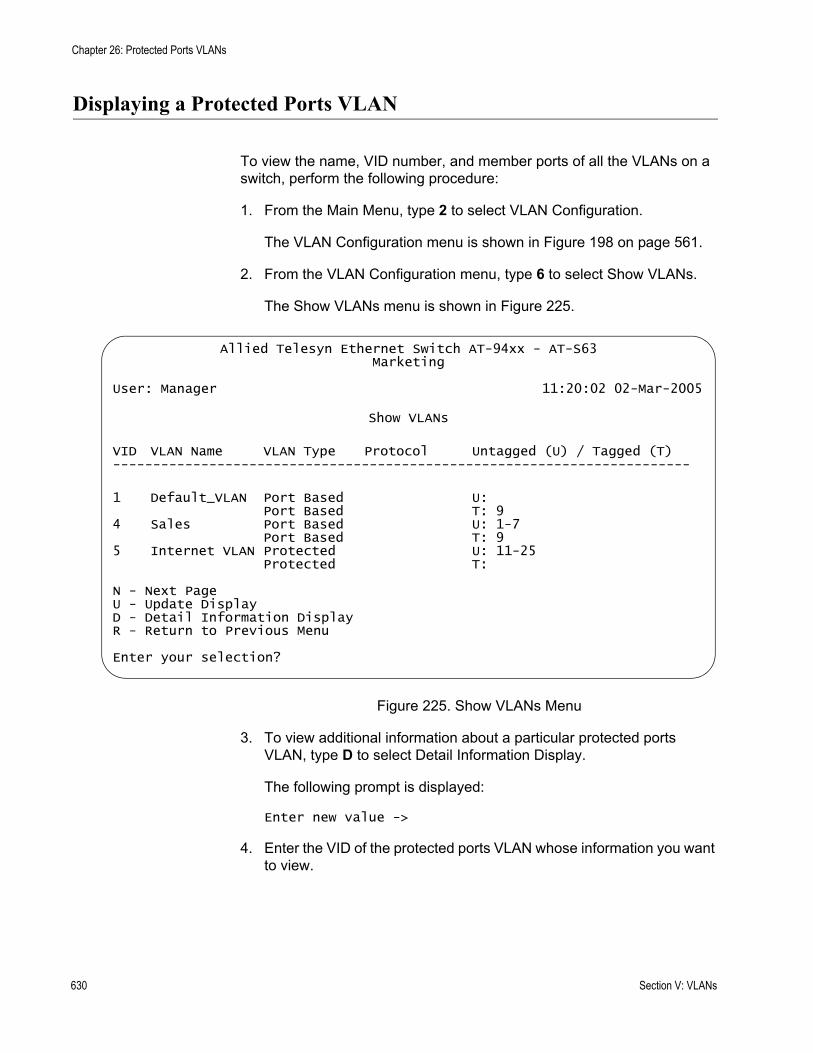
Chapter 26: Protected Ports VLANs
Displaying a Protected Ports VLAN
To view the name, VID number, and member ports of all the VLANs on a switch, perform the following procedure:
1. From the Main Menu, type 2 to select VLAN Configuration.
The VLAN Configuration menu is shown in Figure 198 on page 561.
2. From the VLAN Configuration menu, type 6 to select Show VLANs.
The Show VLANs menu is shown in Figure 225.
Figure 225. Show VLANs Menu
3. To view additional information about a particular protected ports VLAN, type D to select Detail Information Display.
The following prompt is displayed:
Enter new value ->
4. Enter the VID of the protected ports VLAN whose information you want to view.
Allied Telesyn Ethernet Switch AT-94xx - AT-S63Marketing
User: Manager 11:20:02 02-Mar-2005
Show VLANs
VID VLAN Name VLAN Type Protocol Untagged (U) / Tagged (T)------------------------------------------------------------------------
1 Default_VLAN Port Based U: Port Based T: 9
4 Sales Port Based U: 1-7Port Based T: 9
5 Internet VLAN Protected U: 11-25Protected T:
N - Next PageU - Update DisplayD - Detail Information DisplayR - Return to Previous Menu
Enter your selection?
630 Section V: VLANs

AT-S63 Management Software Menus Interface User’s Guide
An example of the Show VLANs window is shown in Figure 226.
Figure 226. Show VLANs Menu
Section 1 lists all the tagged and untagged ports in the protected ports VLAN.
Section 2 lists each group in the VLAN, starting with the uplink port(s). The groups are listed by group number followed by the port numbers. For example, in Figure 226 the uplink port for the VLAN is port 25 and Group 1 consists of ports 12 and 13.
Allied Telesyn Ethernet Switch AT-94xx - AT-S63Marketing
User: Manager 11:20:02 02-Mar-2005
Show VLANs
VID VLAN Name VLAN Type Protocol Untagged (U) / Tagged (T)------------------------------------------------------------------
5 Internet_VLAN Protected U: 12-24Protected T: 25Group Ports---------------------------------------------Uplink 251 12-132 14-153 164 175 18-20
N - Next PageU - Update DisplayR - Return to Previous Menu
Enter your selection?
Section 1
Section 2
Section V: VLANs 631
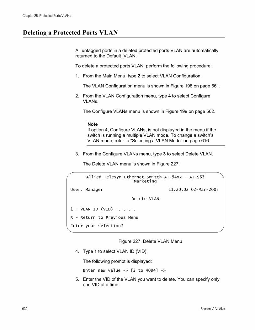
Chapter 26: Protected Ports VLANs
Deleting a Protected Ports VLAN
All untagged ports in a deleted protected ports VLAN are automatically returned to the Default_VLAN.
To delete a protected ports VLAN, perform the following procedure:
1. From the Main Menu, type 2 to select VLAN Configuration.
The VLAN Configuration menu is shown in Figure 198 on page 561.
2. From the VLAN Configuration menu, type 4 to select Configure VLANs.
The Configure VLANs menu is shown in Figure 199 on page 562.
NoteIf option 4, Configure VLANs, is not displayed in the menu if the switch is running a multiple VLAN mode. To change a switch’s VLAN mode, refer to “Selecting a VLAN Mode” on page 616.
3. From the Configure VLANs menu, type 3 to select Delete VLAN.
The Delete VLAN menu is shown in Figure 227.
Figure 227. Delete VLAN Menu
4. Type 1 to select VLAN ID (VID).
The following prompt is displayed:
Enter new value -> [2 to 4094] ->
5. Enter the VID of the VLAN you want to delete. You can specify only one VID at a time.
Allied Telesyn Ethernet Switch AT-94xx - AT-S63Marketing
User: Manager 11:20:02 02-Mar-2005
Delete VLAN
1 - VLAN ID (VID) ........
R - Return to Previous Menu
Enter your selection?
632 Section V: VLANs
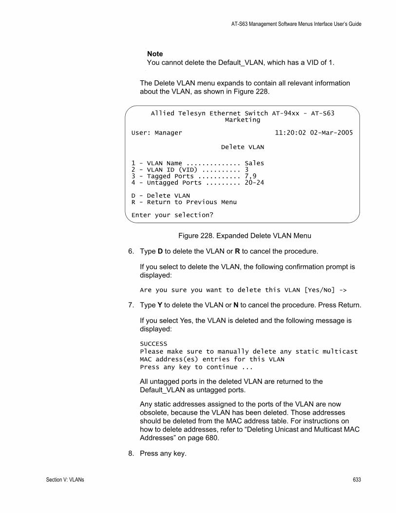
AT-S63 Management Software Menus Interface User’s Guide
NoteYou cannot delete the Default_VLAN, which has a VID of 1.
The Delete VLAN menu expands to contain all relevant information about the VLAN, as shown in Figure 228.
Figure 228. Expanded Delete VLAN Menu
6. Type D to delete the VLAN or R to cancel the procedure.
If you select to delete the VLAN, the following confirmation prompt is displayed:
Are you sure you want to delete this VLAN [Yes/No] ->
7. Type Y to delete the VLAN or N to cancel the procedure. Press Return.
If you select Yes, the VLAN is deleted and the following message is displayed:
SUCCESSPlease make sure to manually delete any static multicast MAC address(es) entries for this VLANPress any key to continue ...
All untagged ports in the deleted VLAN are returned to the Default_VLAN as untagged ports.
Any static addresses assigned to the ports of the VLAN are now obsolete, because the VLAN has been deleted. Those addresses should be deleted from the MAC address table. For instructions on how to delete addresses, refer to “Deleting Unicast and Multicast MAC Addresses” on page 680.
8. Press any key.
Allied Telesyn Ethernet Switch AT-94xx - AT-S63Marketing
User: Manager 11:20:02 02-Mar-2005
Delete VLAN
1 - VLAN Name .............. Sales2 - VLAN ID (VID) .......... 33 - Tagged Ports ........... 7,94 - Untagged Ports ......... 20-24
D - Delete VLANR - Return to Previous Menu
Enter your selection?
Section V: VLANs 633

Chapter 26: Protected Ports VLANs
9. Repeat this procedure starting with Step 4 to delete other VLANs.
10. After making changes, type R until you return to the Main Menu. Then type S to select Save Configuration Changes.
634 Section V: VLANs

Section VI
Port Security
The chapters in this section provide information and procedures for basic switch setup using the AT-S63 management software. The chapters include:
Chapter 27, “Port Security” on page 637Chapter 28, “802.1x Port-based Network Access Control” on page 647Chapter 29, “MAC Address Table” on page 671
Section IV: Port Security 635

636 Section IV: Port Security
Chapter 27
Port Security
This chapter explains how you can use the dynamic and static MAC addresses learned on the ports of the switch to control which end nodes can forward packets through the device. The sections in this chapter include:
“MAC Address Security Overview” on page 638“Configuring MAC Address Port Security” on page 641“Displaying Port Security Levels” on page 644
NoteThis type of port security does not apply to ports located on optional GBIC and SFP modules.
Section IV: Port Security 637

Chapter 27: Port Security
MAC Address Security Overview
This feature can enhance the security of your network. You can use it to control which end nodes can forward frames through the switch, and so prevent unauthorized individuals from accessing your network or particular parts of the network.
This type of network security uses a frame’s source MAC address to determine whether the switch should forward a frame or discard it. The source address is the MAC address of the end node that sent the frame.
There are four levels of port security:
AutomaticLimitedSecuredLocked
You set port security on a per port basis. Only one security level can be active on a port at a time.
Automatic The Automatic security mode disables port security on a port. This is the default security level for a port.
A dynamic MAC address learned by a port operating with this security level is deleted from the MAC address table after the end node is inactive for a specified period of time. This prevents the table from becoming full of MAC addresses of inactive nodes. The length of time an inactive dynamic MAC address remains in the table is determined by the MAC aging time.
Limited The Limited security level allows you to specify the maximum number of dynamic MAC addresses a port can learn. After a port has learned its maximum number of addresses, it discards all ingress frames with source MAC addresses not already learned.
When the Limited security mode is initially activated on a port, all dynamic MAC addresses learned by the port are deleted from the MAC address table. The port then begins to learn new addresses, up to the maximum allowed. After the port has learned its maximum number of addresses, it does not learn any new addresses, even when end nodes are inactive.
A dynamic MAC address learned on a port operating in the Limited security mode never times out from the MAC address table, even when the corresponding end node is inactive.
Static MAC addresses are retained by the port and are not included in the count of maximum dynamic addresses. You can continue to add static MAC addresses to a port operating with this security level, even after the
638 Section IV: Port Security
AT-S63 Management Software Menus Interface User’s Guide
port has already learned its maximum number of dynamic MAC addresses. A switch port can have up to 255 dynamic and static MAC addresses.
Secured The Secured security level instructs a port to forward frames using only static MAC address. The port does not learn any dynamic MAC addresses and deletes any dynamic addressees that it has already learned. Only those end nodes whose MAC addresses have been entered as static addresses are able to forward frames through the port.
After you have activated this security level, you must enter the static MAC addresses of the end nodes that will be allowed to forward frames through the port.
Locked The Locked security level causes a port to immediately stop learning new dynamic MAC addresses. Frames are forwarded using the dynamic MAC addresses that the port has already learned and any static MAC addresses assigned to the port.
Dynamic MAC addresses learned by the port prior to the activation of this security level never time out from the MAC address table, even when the corresponding end nodes are inactive. However, the port does not learn new dynamic addresses.
You can continue to add new static MAC addresses to a port operating under this security level.
NoteFor background information on MAC addresses and aging time, refer to “MAC Address Overview” on page 672.
SecurityViolations and
Intrusion Actions
When a port receives an invalid frame, it has to decide what action it takes. This is what is referred to as intrusion action.
Before defining the intrusion actions, it helps to understand what constitutes an invalid frame. This differs for each security level, as explained here:
Limited Security Level - An invalid frame for this security level is an ingress frame with a source MAC address not already learned by a port after the port had reached its maximum number of dynamic MAC addresses, or that was not assigned to the port as a static address.Secured Security Level - An invalid frame for this security level is an ingress frame with a source MAC address that was not entered as a static address on the port.Locked - An invalid frame for this security level is an ingress frame with a source MAC address that the port has not already learned or that was not assigned as a static address.
Section IV: Port Security 639
Chapter 27: Port Security
Intrusion action defines what a port does when it receives an invalid frame. For a port operating under either the Secured or Locked security mode, the intrusion action is always the same. The port discards the frame.
But with the Limited security mode you can specify an intrusion action. Here are the options:
Discard the invalid frame.Discard the invalid frame and send an SNMP trap. (SNMP must be enabled on the switch for the trap to be sent.)Discard the invalid frame, send an SNMP trap, and disable the port.
MAC AddressSecurity
Guidelines
Following are several general guidelines to keep in mind when using this type of port security:
The filtering of a packet occurs on the ingress port, not on the egress port.MAC address security can be set from a local or Telnet management session, but not from a web browser management session.You cannot use MAC address security and port-based access control on the same port.
640 Section IV: Port Security
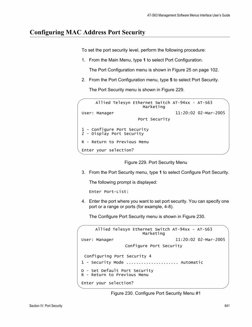
AT-S63 Management Software Menus Interface User’s Guide
Configuring MAC Address Port Security
To set the port security level, perform the following procedure:
1. From the Main Menu, type 1 to select Port Configuration.
The Port Configuration menu is shown in Figure 25 on page 102.
2. From the Port Configuration menu, type 5 to select Port Security.
The Port Security menu is shown in Figure 229.
Figure 229. Port Security Menu
3. From the Port Security menu, type 1 to select Configure Port Security.
The following prompt is displayed:
Enter Port-List:
4. Enter the port where you want to set port security. You can specify one port or a range or ports (for example, 4-8).
The Configure Port Security menu is shown in Figure 230.
Figure 230. Configure Port Security Menu #1
Allied Telesyn Ethernet Switch AT-94xx - AT-S63Marketing
User: Manager 11:20:02 02-Mar-2005
Port Security
1 - Configure Port Security2 - Display Port Security
R - Return to Previous Menu
Enter your selection?
Allied Telesyn Ethernet Switch AT-94xx - AT-S63Marketing
User: Manager 11:20:02 02-Mar-2005
Configure Port Security
Configuring Port Security 4
1 - Security Mode ..................... Automatic
D - Set Default Port SecurityR - Return to Previous Menu
Enter your selection?
Section IV: Port Security 641
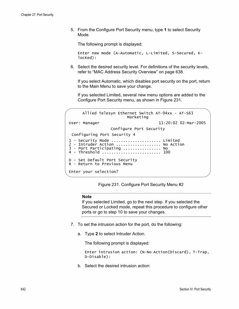
Chapter 27: Port Security
5. From the Configure Port Security menu, type 1 to select Security Mode.
The following prompt is displayed:
Enter new mode (A-Automatic, L-Limited, S-Secured, K-locKed):
6. Select the desired security level. For definitions of the security levels, refer to “MAC Address Security Overview” on page 638.
If you select Automatic, which disables port security on the port, return to the Main Menu to save your change.
If you selected Limited, several new menu options are added to the Configure Port Security menu, as shown in Figure 231.
Figure 231. Configure Port Security Menu #2
NoteIf you selected Limited, go to the next step. If you selected the Secured or Locked mode, repeat this procedure to configure other ports or go to step 10 to save your changes.
7. To set the intrusion action for the port, do the following:
a. Type 2 to select Intruder Action.
The following prompt is displayed:
Enter intrusion action: (N-No Action(Discard), T-Trap, D-Disable):
b. Select the desired intrusion action:
Allied Telesyn Ethernet Switch AT-94xx - AT-S63Marketing
User: Manager 11:20:02 02-Mar-2005
Configure Port Security
Configuring Port Security 4
1 - Security Mode ..................... Limited2 - Intruder Action ................... No Action3 - Port Participating ................ No4 - Threshold ......................... 100
D - Set Default Port SecurityR - Return to Previous Menu
Enter your selection?
642 Section IV: Port Security
AT-S63 Management Software Menus Interface User’s Guide
N - No Action (Discard): The port discards invalid frames. This is the default.
T - Trap: The port discards invalid frames and sends an SNMP trap.
D - Disable: The port discards invalid frames, sends an SNMP trap, and disables the port.
8. If you selected the trap or disable intrusion action, type 3 to toggle the Port Participating option to Yes.
Option 3, Port Participating, applies only when the intrusion action is set to trap or disable. This option does not apply when intrusion action is set to No Action (discard). If this option is set to No when intrusion action is set to trap or disable, the port discards invalid packets, but it does not send an SNMP trap or disable the port. If you want the switch to send a trap and/or disable the port, be sure to sent this option to Yes.
9. If you selected the Limited security mode for the port, do the following to specify the maximum number of dynamic MAC addresses you want the port to be able to learn:
a. Type 4 to select Threshold.
The following prompt is displayed:
Enter port security threshold: [1 to 256] -> 100
b. Enter the maximum number of dynamic MAC addresses you want the port to be able to learn. The range is 1 to 256. The default is 100.
NoteOption D, Select Default Port Security, sets the security mode for the port to the default value of Automatic.
10. After making changes, type R until you return to the Main Menu. Then type S to select Save Configuration Changes.
11. If you configured a port for Secure security level, remember to enter the static MAC addresses of the end nodes that can send packets through the port. For instructions on how to add static MAC addresses, refer to “Adding Static Unicast and Multicast MAC Addresses” on page 678.
Section IV: Port Security 643
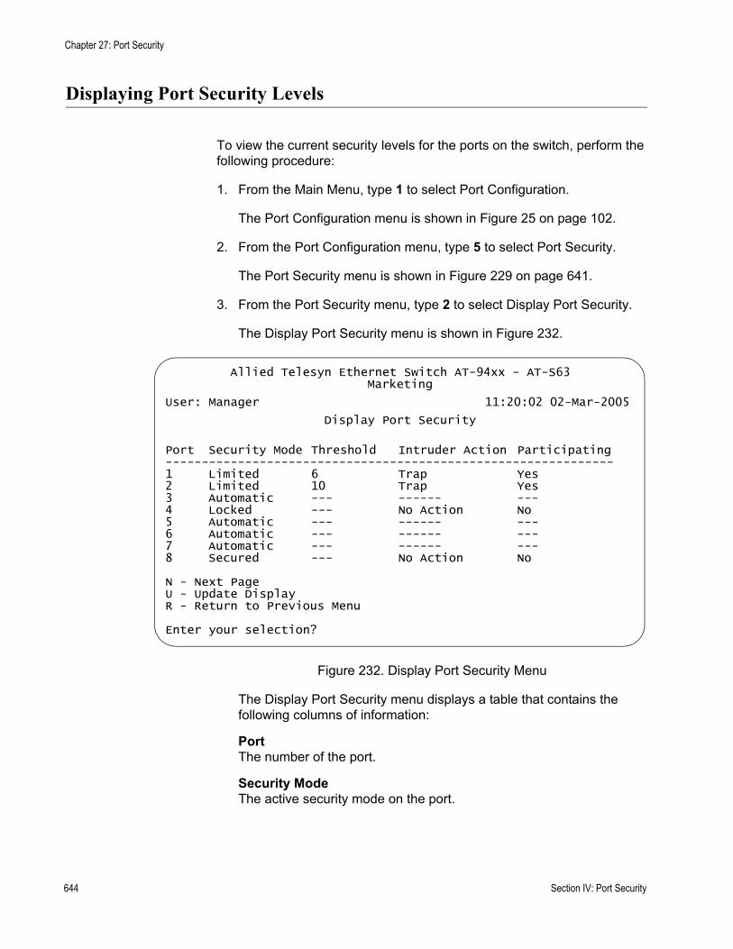
Chapter 27: Port Security
Displaying Port Security Levels
To view the current security levels for the ports on the switch, perform the following procedure:
1. From the Main Menu, type 1 to select Port Configuration.
The Port Configuration menu is shown in Figure 25 on page 102.
2. From the Port Configuration menu, type 5 to select Port Security.
The Port Security menu is shown in Figure 229 on page 641.
3. From the Port Security menu, type 2 to select Display Port Security.
The Display Port Security menu is shown in Figure 232.
Figure 232. Display Port Security Menu
The Display Port Security menu displays a table that contains the following columns of information:
PortThe number of the port.
Security ModeThe active security mode on the port.
Allied Telesyn Ethernet Switch AT-94xx - AT-S63Marketing
User: Manager 11:20:02 02-Mar-2005
Display Port Security
Port Security Mode Threshold Intruder Action Participating--------------------------------------------------------------1 Limited 6 Trap Yes2 Limited 10 Trap Yes3 Automatic --- ------ ---4 Locked --- No Action No5 Automatic --- ------ ---6 Automatic --- ------ ---7 Automatic --- ------ ---8 Secured --- No Action No
N - Next PageU - Update DisplayR - Return to Previous Menu
Enter your selection?
644 Section IV: Port Security
AT-S63 Management Software Menus Interface User’s Guide
ThresholdThe maximum number of dynamic MAC addresses the port learns. It only applies when a port is operating in the Limited security mode.
Intruder ActionThe action taken by the switch if a port receives an invalid frame. The possible settings are:
No Action (Discard) - The port discards invalid frames. This is the default.
Trap - The port discards invalid frames and sends a trap. This applies only to the Limited security mode.
Trap/Disable - The port discards invalid frames, sends a trap, and disables the port. This applies only to the Limited security mode.
ParticipatingThis column applies only when the intrusion action for a port is set to trap or disable. This option does not apply when intrusion action is set to No Action (discard). If this option is set to No when intrusion action is set to trap or disable, the port discards invalid packets, but it does not send a trap or disable the port.
Section IV: Port Security 645

Chapter 27: Port Security
646 Section IV: Port Security

Chapter 28
802.1x Port-based Network Access Control
This chapter explains 802.1x Port-based Network Access Control and how you can use this feature to restrict access to the network ports on the switch. Sections are as follows:
“IEEE 802.1x Port-based Network Access Control Overview” on page 648“Setting Port Roles” on page 657“Enabling or Disabling 802.1x Port-based Network Access Control” on page 659“Configuring Authenticator Port Parameters” on page 660“Configuring Supplicant Port Parameters” on page 664“Displaying the Port Access Parameters” on page 667“Configuring RADIUS Accounting” on page 669
Section IV: Port Security 647

Chapter 28: 802.1x Port-based Network Access Control
IEEE 802.1x Port-based Network Access Control Overview
The AT-S63 management software offers you several different methods for protecting your network and its resources from unauthorized access. For instance, Chapter 27, “Port Security” on page 637, explains how you can restrict network access using the MAC addresses that belong to the end nodes of your network.
This chapter explains yet another way. This method is referred to as Port-based Network Access Control (IEEE 802.1x). It uses the RADIUS protocol to control who can send traffic through and receive traffic from a switch port. With this feature, the switch does not allow an end node to send or receive traffic through a port until the user of the node has logged on by entering a username and password that the RADIUS server has validated.
The benefit of this type of network security is obvious. This feature can prevent an unauthorized individual from connecting a computer to a switch port or using an unattended workstation to access your network resources. Only those users to whom you have assigned valid usernames and passwords are able to use the switch to access the network.
This port security method uses the RADIUS authentication protocol. The AT-S63 management software is shipped with RADIUS client software. If you have already read Chapter 34, “TACACS+ and RADIUS Protocols” on page 761, then you know that you can use the RADIUS client software on the switch, along with a RADIUS server on your network, to create new manager accounts that control who can manage and change the AT-S63 parameter on the switch.
NoteRADIUS with Extensible Authentication Protocol (EAP) extensions is the only supported authentication server for this feature. This feature is not supported with the TACACS+ authentication protocol. The switch supports only one authentication protocol at a time. Therefore, if you want to implement IEEE 802.1 port access control and also create new manager accounts as explained in Chapter 34, “TACACS+ and RADIUS Protocols” on page 761, you must use the RADIUS protocol.
Following are several terms to keep in mind when you use this feature.
Supplicant - A supplicant is an end user or end node that wants to access the network through a switch port. A supplicant is also referred to as a client.
648 Section IV: Port Security
AT-S63 Management Software Menus Interface User’s Guide
Authenticator - The authenticator is a port on the switch that prohibits network access by a supplicant until the network user has entered a valid username and password.Authentication server - The authentication server is the network device that has the RADIUS server software. This is the device that does the actual authenticating of the user names and password from the supplicants.
The AT-9400 Series switch does not authenticate any of the username and passwords from the end users. Rather, it acts as an intermediary between a supplicant and the authentication server during the authentication process.
AuthenticationProcess
Below is a brief overview of the authentication process that occurs between a supplicant, authenticator, and authentication server. For further details, refer to the IEEE 802.1x standard.
Either the authenticator (that is, a switch port) or the supplicant initiates an authentication message exchange. The switch initiates an exchange when it detects a change in the status of a port (such as when the port transitions from no link to valid link), or if it receives a packet on the port with a source MAC address not in the MAC address table.An authenticator starts the exchange by sending an EAP-Request/Identity packet. A supplicant starts the exchange with an EAPOL-Start packet, to which the authenticator responds with a EAP-Request/Identity packet.The supplicant responds with an EAP-Response/Identity packet to the authentication server via the authenticator.The authentication server responds with an EAP-Request packet to the supplicant via the authenticator.The supplicant responds with an EAP-Response/MDS packet containing a username and password.The authentication server sends either an EAP-Success packet or EAP-Reject packet to the supplicant.Upon successful authorization of the supplicant by the authentication server, the switch adds the supplicant’s MAC address to the MAC address as an authorized address and begins forwarding network traffic to and from the port.When the supplicant sends an EAPOL-Logoff message, the switch removes the supplicant’s MAC address from the MAC address table, preventing the supplicant from sending or receiving any further traffic from the port.
Section IV: Port Security 649

Chapter 28: 802.1x Port-based Network Access Control
Port Roles Part of the task of implementing this feature is specifying the roles of the ports on the switch. A port can have one of three roles:
NoneAuthenticatorSupplicant
None Role
A switch port in the None role does not participate in port-based access control. Any device can connect to the port and send traffic through it and receive traffic from it without providing a username and password. This is the default setting for the switch ports.
Set a port to this role if you do not want to require its client to log on to use the network. This is also the correct role for a port that is connected to an authentication server. Because an authentication server cannot authenticate itself, the switch port to which it is connected must be set to this role.
Authenticator Role
Placing a switch port in the authenticator role activates port access control on the port. A port in the role of authenticator does not forward network traffic to or from the end node until the client has entered a username and password and the authentication server has validated them.
Determining whether a switch port should be set to the authenticator role is straightforward. If you want the user of the end node connected to the port to log in before using the network, then you should set the switch port to the authenticator role.
Figure 233 illustrates this concept. Port 2 on the switch has been set to the authenticator role because it is connected to an end node with 802.1x client software. The end user at the workstation must log on to use the network.
650 Section IV: Port Security
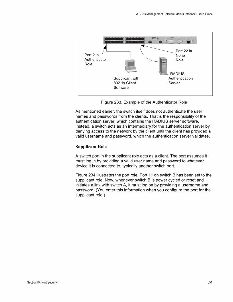
AT-S63 Management Software Menus Interface User’s Guide
Figure 233. Example of the Authenticator Role
As mentioned earlier, the switch itself does not authenticate the user names and passwords from the clients. That is the responsibility of the authentication server, which contains the RADIUS server software. Instead, a switch acts as an intermediary for the authentication server by denying access to the network by the client until the client has provided a valid username and password, which the authentication server validates.
Supplicant Role
A switch port in the supplicant role acts as a client. The port assumes it must log in by providing a valid user name and password to whatever device it is connected to, typically another switch port.
Figure 234 illustrates the port role. Port 11 on switch B has been set to the supplicant role. Now, whenever switch B is power cycled or reset and initiates a link with switch A, it must log on by providing a username and password. (You enter this information when you configure the port for the supplicant role.)
FAULT
RPS
MASTER
POWER
CLASS 1LASER PRODUCT
STATUSTERMINALPORT
1 3 5 7 9 11
2 4 6 8 10 12
13 15 17 19 21 23R
14 16 18 20 22 24R
AT-9424T/SP Gigabit Ethernet Switch
1 3 5 7 9 11 13 15 17 19 21 23R
2 4 6 8 10 12 14 16 18 20 22 24R
23 24
L/A
D/C
D/C
L/A
D/C
L/A 1000 LINK / ACT
HDX / COLFDX
10/100 LINK / ACTPORT ACTIVITY
L/A
1000 LINK / ACTSFPSFP
24
SFP
23
RADIUSAuthenticationServer
Supplicant with802.1x ClientSoftware
Port 2 inAuthenticatorRole
Port 22 inNoneRole
Section IV: Port Security 651

Chapter 28: 802.1x Port-based Network Access Control
Figure 234. Example of the Supplicant Role
NoteStrictly limit the use of this port role. Otherwise, undesirable switch operation may result. Use this port role only when the link will carry traffic from just one client or only management traffic. Set ports used to interconnect switches to the none role.
RADIUSAccounting
The AT-S63 management software supports RADIUS accounting for switch ports set to the Authenticator role. This feature allows the switch to send information to the RADIUS server about the status of its supplicants. You can view this information on the RADIUS server to monitor network activity and use.
The switch sends accounting information to the RADIUS server when one of the following events occur:
Supplicant logs onSupplicant logs offA change in the status of an Authenticator port during an active Supplicant session (for example, the port is reset or is changed from the Authenticator role to None role while a Supplicant is logged on)
The information sent by the switch to the RADIUS server for an event includes:
Port number where the event occurredThe date and time when the event occurred
Switch A
Switch B
FAULT
RPS
MASTER
POWER
CLASS 1LASER PRODUCT
STATUSTERMINALPORT
1 3 5 7 9 11
2 4 6 8 10 12
13 15 17 19 21 23R
14 16 18 20 22 24R
AT-9424T/SP Gigabit Ethernet Switch
1 3 5 7 9 11 13 15 17 19 21 23R
2 4 6 8 10 12 14 16 18 20 22 24R
23 24
L/A
D/C
D/C
L/A
D/C
L/A 1000 LINK / ACT
HDX / COLFDX
10/100 LINK / ACTPORT ACTIVITY
L/A
1000 LINK / ACTSFPSFP
24
SFP
23
Port 6in AuthenticatorRole
Port 11in Supplicant Role
RADIUSAuthenticationServer
652 Section IV: Port Security

AT-S63 Management Software Menus Interface User’s Guide
The number of packets transmitted and received by the switch port during a supplicant’s session. (This information is sent only when the client logs off.)
You can also configure the accounting feature to send interim updates so you can monitor which clients are still active.
Here are a few guidelines to using the accounting feature:
The AT-S63 management software supports the Network level of accounting, but not the System or Exec.This feature is only available for ports operating in the Authenticator role. No accounting is provided for ports operating in the Supplicant or None role.You must configure 802.1x Port-based Network Access Control as explained in this chapter and designate the Authenticator ports.You must also specify from one to three RADIUS servers. The instructions for this are in “Configuring RADIUS” on page 771.
For instructions on configuring this feature, refer to “Configuring RADIUS Accounting” on page 669.
General Steps Following are the general steps for implementing 802.1x Port-based Network Access Control and RADIUS accounting on the switch:
1. You must install RADIUS server software on one or more of your network servers or management stations. Authentication protocol server software is not available from Allied Telesyn. Funk Software Steel-Belted Radius and Free Radius have been verified as fully compatible with the AT-S63 management software.
NoteThis feature is not supported with the TACACS+ authentication protocol.
2. You need to install 802.1x client software on those workstations that are to be supplicants. Microsoft WinXP client software and Meeting House Aegis client software have been verified as fully compatible with the AT-S63 management software.
3. You must configure and activate the RADIUS client software in the AT-S63 management software. The default setting for the authentication protocol is disabled. You will need to provide the following information:
The IP addresses of up to three RADIUS servers. The encryption key used by the authentication servers.
Section IV: Port Security 653
Chapter 28: 802.1x Port-based Network Access Control
The instructions for this step are in “Configuring TACACS+” on page 767.
4. Next, you must configure the port access control settings on the switch. This involves the following:
Specifying the port roles.Configuring 802.1x port parameters.Enabling 802.1x Port-based Network Access Control.
The instructions for this step are found in this chapter.
5. Finally, if you want to use RADIUS accounting to monitor the supplicants connected to the switch ports, you must configure the service on the switch, as explained in “Configuring RADIUS Accounting” on page 669.
Port-basedNetwork Access
ControlGuidelines
Following are the guidelines for using this feature:
Ports operating under port-based access control do not support port trunking or dynamic MAC address learning.The appropriate port role for a port on an AT-9400 Series switch connected to an authentication server is None.The authentication server must be a member of the management VLAN. For information about management VLANs, refer to “Specifying a Management VLAN” on page 581.Allied Telesyn does not support connecting more than one supplicant to an authenticator port on the switch. The switch allows only one supplicant to log on per port.
NoteConnecting multiple supplicants to a switch port set to the authenticator role does not conform to the IEEE 802.1x standard. This can introduce security risks and can result in undesired switch behavior. To avoid this, Allied Telesyn recommends not applying the authenticator role to a port that is connected to more than one end node, such as a port connected to another switch or to a hub.
If a switch port set to the supplicant role is connected to a port on another switch that is not set to authenticator, the port, after a timeout period, assumes that it can send traffic without having to log on.A username and password combination is not tied to the MAC address of an end node. This allows end users to use the same username and password when working at different workstations.After a supplicant has successfully logged on, the MAC address of the end node is added to the switch’s MAC address table as an authenticated address. It remains in the table until the end user logs off
654 Section IV: Port Security

AT-S63 Management Software Menus Interface User’s Guide
the network. Only then is the address removed. The address is not timed out, even if the end node becomes inactive.
NoteEnd users of port-based access control should be instructed to always log off when they are finished with a work session. This prevents unauthorized individuals from accessing the network through unattended network workstations.
You cannot use the MAC address port security feature, described in Chapter 27, “Port Security” on page 637, on switch ports that are set to the authenticator or supplicant role. A port’s MAC address security level must be Automatic.There should be only one port in the authenticator role between a client and the authentication server.A switch port in the authenticator role transmits broadcast and multicast traffic even when the client connected to the port has not logged on.An authenticator port can be tagged or untagged.Set ports used to interconnect switches to the none role. This is illustrated in Figure 235.
Figure 235. Port-based Authentication Across Multiple Switches
Switch A
Switch B
FAULT
RPS
MASTER
POWER
CLASS 1LASER PRODUCT
STATUSTERMINALPORT
1 3 5 7 9 11
2 4 6 8 10 12
13 15 17 19 21 23R
14 16 18 20 22 24R
AT-9424T/SP Gigabit Ethernet Switch
1 3 5 7 9 11 13 15 17 19 21 23R
2 4 6 8 10 12 14 16 18 20 22 24R
23 24
L/A
D/C
D/C
L/A
D/C
L/A 1000 LINK / ACT
HDX / COLFDX
10/100 LINK / ACTPORT ACTIVITY
L/A
1000 LINK / ACTSFPSFP
24
SFP
23
Port 6 in NoneRole
Port 22 in None Role
Port 21 in None Role
FAULT
RPS
MASTER
POWER
CLASS 1LASER PRODUCT
STATUSTERMINALPORT
1 3 5 7 9 11
2 4 6 8 10 12
13 15 17 19 21 23R
14 16 18 20 22 24R
AT-9424T/SP Gigabit Ethernet Switch
1 3 5 7 9 11 13 15 17 19 21 23R
2 4 6 8 10 12 14 16 18 20 22 24R
23 24
L/A
D/C
D/C
L/A
D/C
L/A 1000 LINK / ACT
HDX / COLFDX
10/100 LINK / ACTPORT ACTIVITY
L/A
1000 LINK / ACTSFPSFP
24
SFP
23
RADIUSAuthenticationServer
Ports inAuthenticator Role
Supplicants with802.1x Client Software
Section IV: Port Security 655

Chapter 28: 802.1x Port-based Network Access Control
When 802.1x Port-based Network Access Control is activated on a switch, the feature polls all RADIUS servers specified in the RADIUS configuration. If three servers have been configured, the switch polls all three. If server 1 responds, all future requests go only to that server. If server 1 stops responding, the switch again polls all RADIUS servers. If server 2 responds, but not server 1, then all future requests go to servers 1 and 2. If only server 3 responds, then all future requests go to all three servers.
656 Section IV: Port Security
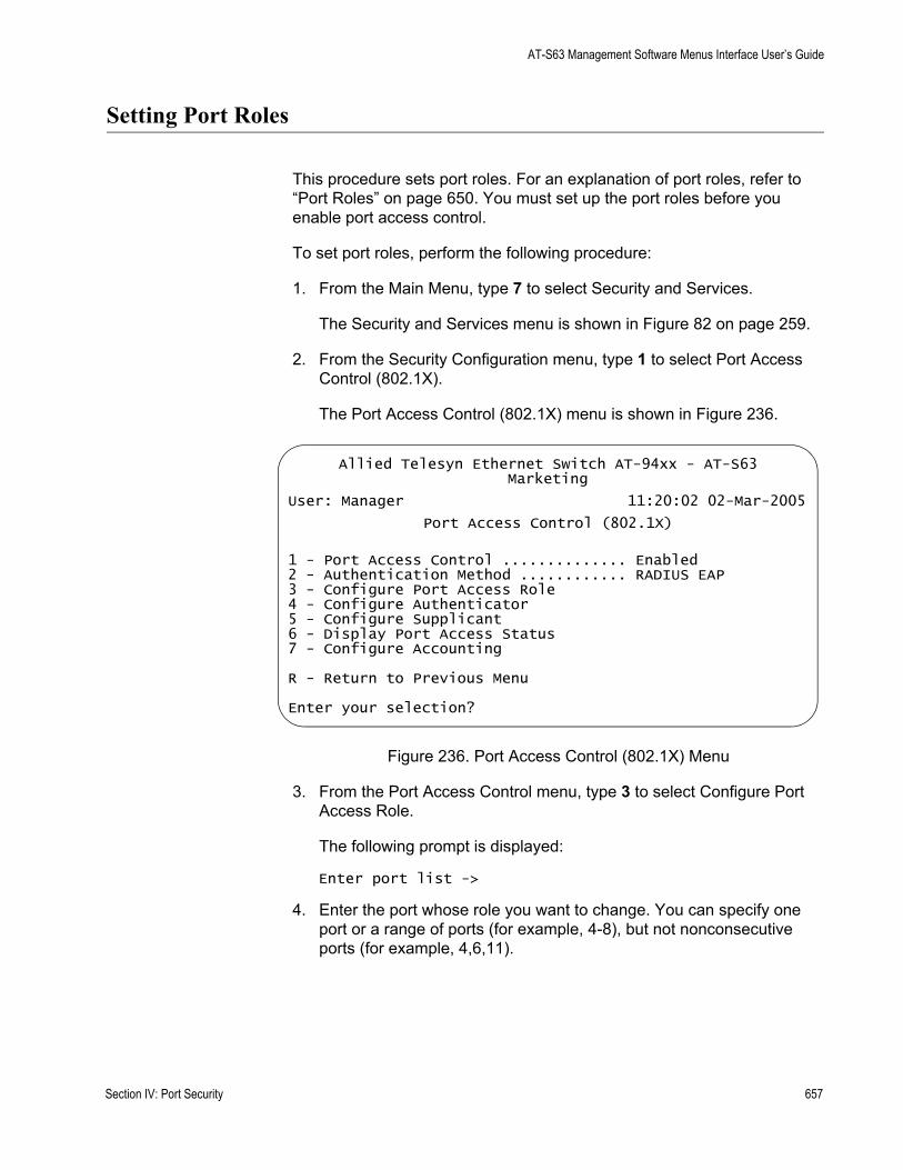
AT-S63 Management Software Menus Interface User’s Guide
Setting Port Roles
This procedure sets port roles. For an explanation of port roles, refer to “Port Roles” on page 650. You must set up the port roles before you enable port access control.
To set port roles, perform the following procedure:
1. From the Main Menu, type 7 to select Security and Services.
The Security and Services menu is shown in Figure 82 on page 259.
2. From the Security Configuration menu, type 1 to select Port Access Control (802.1X).
The Port Access Control (802.1X) menu is shown in Figure 236.
Figure 236. Port Access Control (802.1X) Menu
3. From the Port Access Control menu, type 3 to select Configure Port Access Role.
The following prompt is displayed:
Enter port list ->
4. Enter the port whose role you want to change. You can specify one port or a range of ports (for example, 4-8), but not nonconsecutive ports (for example, 4,6,11).
Allied Telesyn Ethernet Switch AT-94xx - AT-S63Marketing
User: Manager 11:20:02 02-Mar-2005
Port Access Control (802.1X)
1 - Port Access Control .............. Enabled2 - Authentication Method ............ RADIUS EAP3 - Configure Port Access Role4 - Configure Authenticator5 - Configure Supplicant6 - Display Port Access Status7 - Configure Accounting
R - Return to Previous Menu
Enter your selection?
Section IV: Port Security 657
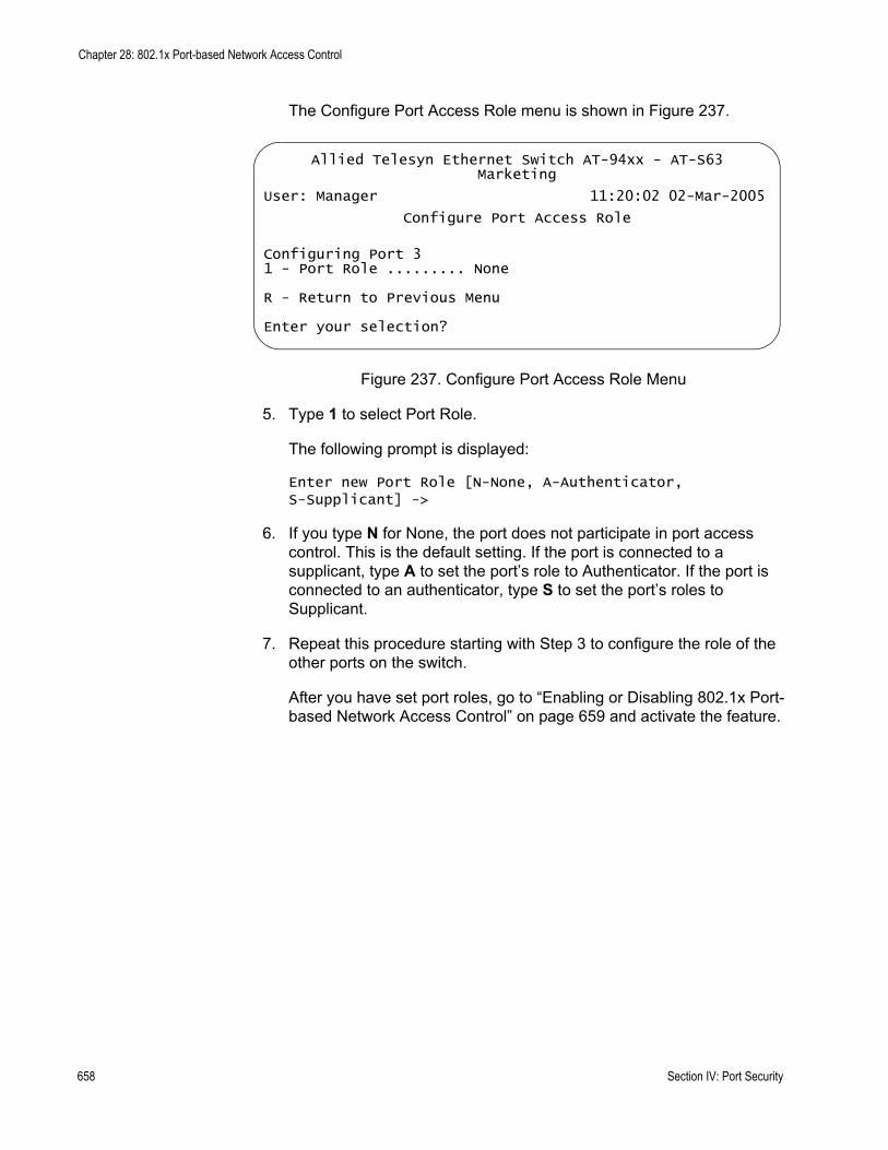
Chapter 28: 802.1x Port-based Network Access Control
The Configure Port Access Role menu is shown in Figure 237.
Figure 237. Configure Port Access Role Menu
5. Type 1 to select Port Role.
The following prompt is displayed:
Enter new Port Role [N-None, A-Authenticator, S-Supplicant] ->
6. If you type N for None, the port does not participate in port access control. This is the default setting. If the port is connected to a supplicant, type A to set the port’s role to Authenticator. If the port is connected to an authenticator, type S to set the port’s roles to Supplicant.
7. Repeat this procedure starting with Step 3 to configure the role of the other ports on the switch.
After you have set port roles, go to “Enabling or Disabling 802.1x Port-based Network Access Control” on page 659 and activate the feature.
Allied Telesyn Ethernet Switch AT-94xx - AT-S63Marketing
User: Manager 11:20:02 02-Mar-2005
Configure Port Access Role
Configuring Port 31 - Port Role ......... None
R - Return to Previous Menu
Enter your selection?
658 Section IV: Port Security
AT-S63 Management Software Menus Interface User’s Guide
Enabling or Disabling 802.1x Port-based Network Access Control
This procedure explains how to enable and disable port-based access control on the switch. If you have not assigned port roles and configured the parameter settings, you should skip this procedure and go first to “Setting Port Roles” on page 657.
To enable or disable 802.1x Port-based Network Access Control, perform the following procedure:
1. From the Main Menu, type 7 to select Security and Services.
The Security and Services menu is shown in Figure 82 on page 259.
2. From the Security Configuration menu, type 1 to select Port Access Control (802.1X).
The Port Access Control (802.1X) menu is shown in Figure 236 on page 657.
3. From the Port Access Control menu, type 1 to select Port Access Control.
The following prompt is displayed:
Port Access Control (E-Enable, D-Disable):
4. Type E to enable port access control, or D to disable port access control.
5. After making changes, type R until you return to the Main Menu. Then type S to select Save Configuration Changes.
Section IV: Port Security 659
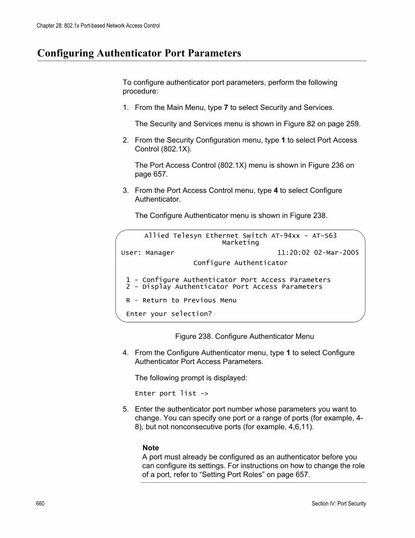
Chapter 28: 802.1x Port-based Network Access Control
Configuring Authenticator Port Parameters
To configure authenticator port parameters, perform the following procedure:
1. From the Main Menu, type 7 to select Security and Services.
The Security and Services menu is shown in Figure 82 on page 259.
2. From the Security Configuration menu, type 1 to select Port Access Control (802.1X).
The Port Access Control (802.1X) menu is shown in Figure 236 on page 657.
3. From the Port Access Control menu, type 4 to select Configure Authenticator.
The Configure Authenticator menu is shown in Figure 238.
Figure 238. Configure Authenticator Menu
4. From the Configure Authenticator menu, type 1 to select Configure Authenticator Port Access Parameters.
The following prompt is displayed:
Enter port list ->
5. Enter the authenticator port number whose parameters you want to change. You can specify one port or a range of ports (for example, 4-8), but not nonconsecutive ports (for example, 4,6,11).
NoteA port must already be configured as an authenticator before you can configure its settings. For instructions on how to change the role of a port, refer to “Setting Port Roles” on page 657.
Allied Telesyn Ethernet Switch AT-94xx - AT-S63Marketing
User: Manager 11:20:02 02-Mar-2005
Configure Authenticator
1 - Configure Authenticator Port Access Parameters2 - Display Authenticator Port Access Parameters
R - Return to Previous Menu
Enter your selection?
660 Section IV: Port Security

AT-S63 Management Software Menus Interface User’s Guide
The Configure Authenticator Port Access Parameters menu is shown in Figure 239.
Figure 239. Configure Authenticator Port Access Parameters Menu
6. Adjust the following parameters as necessary.
0 - Port ControlThe possible settings for this parameter are:
Force-authorized - Disables IEEE 802.1X port-based authentication and causes the port to transition to the authorized state without any authentication exchange required. The port transmits and receives normal traffic without 802.1x-based authentication of the client. This is the default setting
Force-unauthorized - Causes the port to remain in the unauthorized state, ignoring all attempts by the client to authenticate. The switch cannot provide authentication services to the client through the interface
Auto - Enables 802.1x port-based authentication and causes the port to begin in the unauthorized state, allowing only EAPOL frames to be sent and received through the port. The authentication process begins when the link state of the port changes or the port receives an EAPOL-Start packet from a supplicant. The switch requests the identity of the client and begins relaying authentication messages between the client and the authentication server. Each client that attempts to access the network is uniquely identified by the switch using the client's MAC address.
Allied Telesyn Ethernet Switch AT-94xx - AT-S63Marketing
User: Manager 11:20:02 02-Mar-2005
Configure Authenticator Port Access Parameters
Configuring Port 3
0 - Port Control ............. Auto1 - Quiet Period ............. 60 Seconds2 - TX Period ................ 30 Seconds3 - Reauth Enabled ........... Enabled4 - Reauth Period ............ 3600 Seconds5 - Supplicant Timeout ....... 30 Seconds6 - Server Timeout ........... 30 Seconds7 - Max Requests ............. 28 - Control Direction ........ INGRESS9 - Piggyback Mode ........... Disabled
R - Return to Previous Menu
Enter your selection?
Section IV: Port Security 661
Chapter 28: 802.1x Port-based Network Access Control
1 - Quiet PeriodThe quiet period is the number of seconds that the port remains in the quiet state following a failed authentication exchange with the client. The default value is 60 seconds. The range is 0 to 65,535 seconds.
2 - TX PeriodThis parameter sets the number of seconds that the switch waits for a response to an EAP-request/identity frame from the client before retransmitting the request. The default value is 30 seconds. The range is 1 to 65,535 seconds.
3 - Reauth EnabledSpecifies if reauthentication should occur according to the reauthentication period. The options are Enabled or Disabled.
4 - Reauth PeriodThe reauth period enables periodic reauthentication of the client, which is disabled by default. The default value is 3600 seconds. The range is 1 to 65,535 seconds.
5 - Supplicant TimeoutThis parameter sets the switch-to-client retransmission time for the EAP-request frame. The default value for this parameter is 30 seconds. The range is 1 to 600 seconds.
6 - Server TimeoutThis parameter sets the timer used by the switch to determine authentication server timeout conditions. The default value for this parameter is 30 seconds. The range is 1 to 65,535 seconds.
7 - Max RequestsThis parameter specifies the maximum number of times that the switch retransmits an EAP Request packet to the client before it times out the authentication session. The default value for this parameter is 2 retransmissions. The range is 1 to 10 retransmissions.
8 - Control DirectionThis parameter specifies how the port handles ingress and egress broadcast and multicast packets when in the unauthorized state. When a port is set to the Authenticator role, it remains in the unauthorized state until the client logs on by providing a username and password combination. In the unauthorized state, the port only accepts EAP packets from the client. All other ingress packets that the port might receive from the client, including multicast and broadcast traffic, is discarded until the supplicant has logged in. The options are:
Ingress - A port, when in the unauthorized state, discards all ingress broadcast and multicast packets from the client, but forwards all egress broadcast and multicast traffic to the same client.
662 Section IV: Port Security
AT-S63 Management Software Menus Interface User’s Guide
Both - A port, when in the unauthorized state, does not forward ingress or egress broadcast and multicast packets from or to the same client until the client logs in. This is the default.
9 - Piggyback ModeThis parameter opens up the port after authentication to all other unauthenticated devices and closes the port when reauthentication takes place. The options are Enabled or Disabled.
7. Repeat this procedure starting with Step 4 to configure additional authenticator ports on the switch.
8. After making changes, type R until you return to the Main Menu. Then type S to select Save Configuration Changes.
Section IV: Port Security 663

Chapter 28: 802.1x Port-based Network Access Control
Configuring Supplicant Port Parameters
To configure supplicant port parameters, perform the following procedure:
1. From the Main Menu, type 7 to select Security and Services.
The Security and Services menu is shown in Figure 82 on page 259.
2. From the Security Configuration menu, type 1 to select Port Access Control (802.1X).
The Port Access Control (802.1X) menu is shown in Figure 236 on page 657.
3. From the Port Access Control menu, type 5 to select Configure Supplicant.
The Configure Supplicant menu is shown in Figure 238.
Figure 240. Configure Supplicant Menu
4. From the Configure Supplicant menu, type 1 to select Configure Authenticator Port Access Parameters.
The following prompt is displayed:
Enter port list ->
5. Enter the supplicant port number whose parameters you want to change. You can specify one port or a range of ports (for example, 4-8), but not multiple individual ports (for example, 4,6,11).
NoteA port must already be configured as an supplicant before you can configure its settings. For instructions on how to change the role of a port, refer to “Setting Port Roles” on page 657.
Allied Telesyn Ethernet Switch AT-94xx - AT-S63Marketing
User: Manager 11:20:02 02-Mar-2005
Configure Supplicant
1 - Configure Supplicant Port Access Parameters2 - Display Supplicant Port Access Parameters
R - Return to Previous Menu
Enter your selection?
664 Section IV: Port Security

AT-S63 Management Software Menus Interface User’s Guide
The Configure Supplicant Port Access Parameters menu is shown in Figure 239.
Figure 241. Configure Supplicant Port Access Parameters Menu
6. Adjust the following parameters as necessary.
1 - Auth PeriodThis parameter specifies the period of time in seconds that the supplicant waits for a reply from the authenticator after sending an EAP-Response frame. The range is 1 to 60 seconds. The default is 30 seconds.
2 - Held PeriodThe held period specifies the amount of time in seconds the supplicant is to refrain from retrying to re-contact the authenticator in the event the end user provides an invalid username and/or password. After the time period has expired, the supplicant can attempt to log on again. The range is 0 to 65,535. The default value is 60.
3 - Max StartMax start is the maximum number of times the supplicant sends EAPOL-Start frames before assuming that there is no authenticator present. The range is 1 to 10. The default is 3.
4 - Start PeriodThe start period is the time period in seconds between successive attempts by the supplicant to establish contact with an authenticator when there is no reply. The range is 1 to 60. The default is 30.
5 - User NameThe user name is the username for the switch port. The port sends the name to the authentication server for verification when the port logs on to the network. The username can be from 1 to 16 alphanumeric characters (A to Z, a to z, 1 to 9). Do not use spaces or special
Allied Telesyn Ethernet Switch AT-94xx - AT-S63Marketing
User: Manager 11:20:02 02-Mar-2005
Configure Supplicant Port Access Parameters
Configuring Port 5-8
1 - Auth Period........... 30 Seconds2 - Held Period........... 60 Seconds3 - Max Start ........... 34 - Start Period.......... 30 Seconds5 - User Name: ...........6 - User Password: .......
R - Return to Previous Menu
Enter your selection?
Section IV: Port Security 665
Chapter 28: 802.1x Port-based Network Access Control
characters, such as asterisks or exclamation points. The username is case sensitive.
6 - User PasswordThis parameter specifies the password for the switch port. The port sends the password to the authentication server for verification when the port logs on to the network. The password can be from 1 to 16 alphanumeric characters (A to Z, a to z, 1 to 9). Do not use spaces or special characters, such as asterisks or exclamation points. The password is case sensitive.
7. Repeat this procedure starting with Step 4 to configure additional supplicant ports on the switch.
8. After making changes, type R until you return to the Main Menu. Then type S to select Save Configuration Changes.
666 Section IV: Port Security

AT-S63 Management Software Menus Interface User’s Guide
Displaying the Port Access Parameters
To display the port access parameters for the ports on the switch, perform the following procedure:
1. From the Main Menu, type 7 to select Security and Services.
The Security and Services menu is shown in Figure 82 on page 259.
2. From the Security Configuration menu, type 1 to select Port Access Control (802.1X).
The Port Access Control (802.1X) menu is shown in Figure 236 on page 657.
3. From the Port Access Control menu, type 6 to select Display Port Access status.
The Display Port Access Status menu is shown in Figure 242.
Figure 242. Display Port Access Status Menu
The Display Port Access Status menu displays a table that contains the following columns of information:
PortPort number.
Allied Telesyn Ethernet Switch AT-94xx - AT-S63Marketing
User: Manager 11:20:02 02-Mar-2005
Display Port Access Status
Port PortRole State Additional Info
---------------------------------------------------------------1 None ------ -------------------2 Authenticator Connecting -------------------3 Authenticator Authenticated 00:a0:d2:18:1a:c84 Authenticator Connecting -------------------5 None ------ -------------------6 None ------ -------------------7 None ------ -------------------8 Supplicant ------ --------------------
N - Next PageU - Update DisplayR - Return to Previous Menu
Enter your selection?
Section IV: Port Security 667

Chapter 28: 802.1x Port-based Network Access Control
Port RolePort access role configured for the port. The possible settings are None, Authenticator, or Supplicant.
StateState of the port. The state field is dependent on whether a port is configured as an authenticator or a supplicant.
When you configure a port with an Authenticator Role, the State field can have the following values:
AbortingAuthenticatedAuthenticatingConnectingDisconnectedForce_AuthForce_UnauthHeldInitialize
When you configure a port with a Supplicant role, the State field can have the following values:
AcquiredAuthenticatedAuthenticatingConnectingDisconnectedHeldLogoff
Additional InfoWhen you assign a port the role of Authenticator and it has a status of Authenticated, this field also displays the MAC address of the Authenticator.
668 Section IV: Port Security
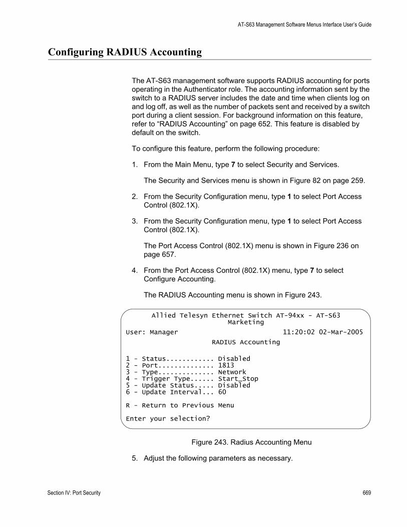
AT-S63 Management Software Menus Interface User’s Guide
Configuring RADIUS Accounting
The AT-S63 management software supports RADIUS accounting for ports operating in the Authenticator role. The accounting information sent by the switch to a RADIUS server includes the date and time when clients log on and log off, as well as the number of packets sent and received by a switch port during a client session. For background information on this feature, refer to “RADIUS Accounting” on page 652. This feature is disabled by default on the switch.
To configure this feature, perform the following procedure:
1. From the Main Menu, type 7 to select Security and Services.
The Security and Services menu is shown in Figure 82 on page 259.
2. From the Security Configuration menu, type 1 to select Port Access Control (802.1X).
3. From the Security Configuration menu, type 1 to select Port Access Control (802.1X).
The Port Access Control (802.1X) menu is shown in Figure 236 on page 657.
4. From the Port Access Control (802.1X) menu, type 7 to select Configure Accounting.
The RADIUS Accounting menu is shown in Figure 243.
Figure 243. Radius Accounting Menu
5. Adjust the following parameters as necessary.
Allied Telesyn Ethernet Switch AT-94xx - AT-S63Marketing
User: Manager 11:20:02 02-Mar-2005
RADIUS Accounting
1 - Status............ Disabled2 - Port.............. 18133 - Type.............. Network4 - Trigger Type...... Start_Stop5 - Update Status..... Disabled6 - Update Interval... 60
R - Return to Previous Menu
Enter your selection?
Section IV: Port Security 669

Chapter 28: 802.1x Port-based Network Access Control
1 - StatusThis parameter activates or deactivates RADIUS accounting on the switch. Select Enabled to activate the feature or Disabled to deactivate it. The default is Disabled.
2 - PortThis parameter specifies the UDP port for RADIUS accounting. The default is port 1813.
3 - TypeThis parameter specifies the type of RADIUS accounting. The default is Network. This value cannot be changed.
4 - Trigger TypeThis parameter specifies the action that causes the switch to send accounting information to the RADIUS server. The options are:
Start_StopThe switch sends accounting information whenever a client logs on or logs off the network. This is the default.
StopThe switch sends accounting information only when a client logs off.
5 - Update StatusThis parameter controls whether the switch is to send interim accounting updates to the RADIUS server. The default is disabled. If you enable this feature, use the next option in the menu to specify the intervals at which the switch is to send the accounting updates.
6 - Update IntervalThis parameter specifies the intervals at which the switch sends interim accounting updates to the RADIUS server. The range is 30 to 300 seconds. The default is 60 seconds.
6. After making changes, type R until you return to the Main Menu. Then type S to select Save Configuration Changes.
670 Section IV: Port Security
Chapter 29
MAC Address Table
This chapter contains the procedures for viewing the static and dynamic MAC address table.
This chapter contains the following sections:
“MAC Address Overview” on page 672“Displaying the MAC Address Tables” on page 674“Adding Static Unicast and Multicast MAC Addresses” on page 678“Deleting Unicast and Multicast MAC Addresses” on page 680“Deleting All Dynamic MAC Addresses” on page 681“Changing the Aging Time” on page 682
Section IV: Port Security 671
Chapter 29: MAC Address Table
MAC Address Overview
Each hardware device that you connect to your Ethernet network has a unique MAC address assigned to it by the device’s manufacturer. For example, every network interface card (NIC) that you use to connect your computers to your network has a MAC address assigned to it by the adapter’s manufacturer.
The AT-9400 Series switch contains a MAC address table with a storage capacity of 16,000 entries. The switch uses the table to store the MAC addresses of the network nodes connected to its ports, along with the port number on which each address was learned.
The switch learns the MAC addresses of the end nodes by examining the source address of each packet received on a port. It adds the address and port on which the packet was received to the MAC table if the address has not already been entered in the table. The result is a table that contains all the MAC addresses of the devices that are connected to the switch’s ports, and the port number where each address was learned.
When the switch receives a packet, it also examines the destination address and, by referring to its MAC address table, determines the port where the destination node is connected. It then forwards the packet to the appropriate port and on to the end node. This increases network bandwidth by limiting each frame to the appropriate port when the intended end node is located, freeing the other switch ports for receiving and transmitting data.
If the switch receives a packet with a destination address that is not in the MAC address table, it floods the packet to all the ports on the switch. If the ports have been grouped into virtual LANs, the switch floods the packet only to those ports which belong to the same VLAN as the port on which the packet was received. This prevents packets from being forwarded onto inappropriate LAN segments and increases network security. When the destination node responds, the switch adds its MAC address and port number to the table.
If the switch receives a packet with a destination address that is on the same port on which the packet was received, it discards the packet without forwarding it on to any port. Because both the source node and the destination node for the packet are located on the same port on the switch, there is no reason for the switch to forward the packet. This too increases network performance by preventing frames from being forwarded unnecessarily to other network devices.
The type of MAC address described above is referred to as a dynamic MAC address. Dynamic MAC addresses are addresses that the switch learns by examining the source MAC addresses of the frames received on the ports.
672 Section IV: Port Security
AT-S63 Management Software Menus Interface User’s Guide
Dynamic MAC addresses are not stored indefinitely in the MAC address table. The switch deletes a dynamic MAC address from the table if it does not receive any frames from the node after a specified period of time. The switch assumes that the node with that MAC address is no longer active and that its MAC address can be purged from the table. This prevents the MAC address table from becoming filled with addresses of nodes that are no longer active.
The period of time that the switch waits before purging an inactive dynamic MAC address is called the aging time. This value is adjustable on the AT-9400 Series switch. The default value is 300 seconds (5 minutes). For instructions on changing the aging timer, refer to “Changing the Aging Time” on page 682.
The MAC address table can also store static MAC addresses. A static MAC address is a MAC address of an end node that you assign to a switch port manually. A static MAC address, after being entered in the table, remains in the table indefinitely and is never deleted, even when the end node is inactive.
You might need to enter static MAC addresses of end nodes the switch does not learn in its normal dynamic learning process, or if you want a MAC address to remain permanently in the table, even when the end node is inactive.
Section IV: Port Security 673
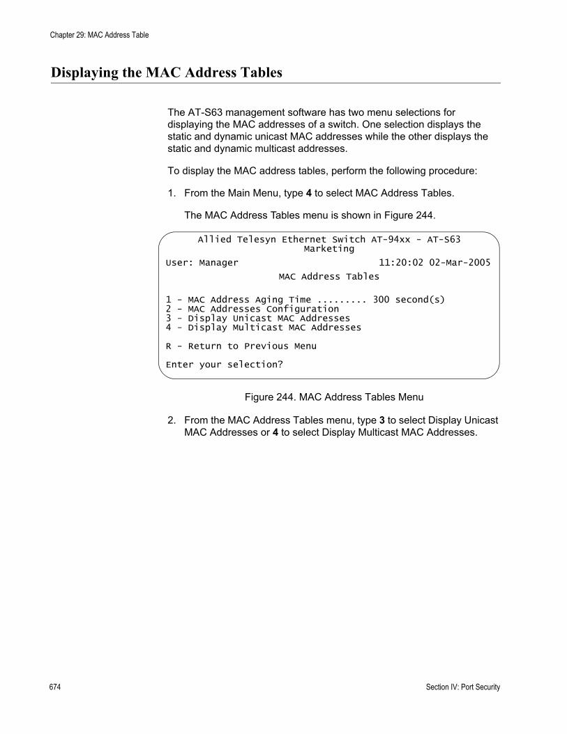
Chapter 29: MAC Address Table
Displaying the MAC Address Tables
The AT-S63 management software has two menu selections for displaying the MAC addresses of a switch. One selection displays the static and dynamic unicast MAC addresses while the other displays the static and dynamic multicast addresses.
To display the MAC address tables, perform the following procedure:
1. From the Main Menu, type 4 to select MAC Address Tables.
The MAC Address Tables menu is shown in Figure 244.
Figure 244. MAC Address Tables Menu
2. From the MAC Address Tables menu, type 3 to select Display Unicast MAC Addresses or 4 to select Display Multicast MAC Addresses.
Allied Telesyn Ethernet Switch AT-94xx - AT-S63Marketing
User: Manager 11:20:02 02-Mar-2005
MAC Address Tables
1 - MAC Address Aging Time ......... 300 second(s)2 - MAC Addresses Configuration3 - Display Unicast MAC Addresses4 - Display Multicast MAC Addresses
R - Return to Previous Menu
Enter your selection?
674 Section IV: Port Security

AT-S63 Management Software Menus Interface User’s Guide
The Display Unicast MAC Addresses menu is shown in Figure 245. The Display Multicast MAC Addresses menu contains the same selections.
Figure 245. Display Unicast MAC Addresses Menu
Choose one of the following display types.
1 - Display AllThis selection displays all dynamic addresses learned on the ports of the switch and all static addresses that have been assigned to the ports. An example of a unicast MAC address table is shown in Figure 246.
Figure 246. Display All Menu - Unicast MAC Addresses
Allied Telesyn Ethernet Switch AT-94xx - AT-S63Marketing
User: Manager 11:20:02 02-Mar-2005
Display Unicast MAC Addresses
1 - Display All2 - Display Static3 - Display Dynamic4 - Display by Port5 - Display Specified MAC6 - Display by VLAN ID7 - Display on Base Ports
R - Return to Previous Menu
Enter your selection?
Allied Telesyn Ethernet Switch AT-94xx - AT-S63Marketing
User: Manager 11:20:02 02-Mar-2005
Display All
Page 1
Total Number of MAC Addresses: 121
MAC Address Port VLANID Type------------------------------------------------------------01:80:C1:00:02:01 0 0 Static (fixed, non-aging)00:a0:d2:18:1a:c8 1 1 Dynamic00:a0:c4:16:3b:80 2 1 Dynamic00:a0:12:c2:10:c6 3 1 Dynamic00:a0:c2:09:10:d8 4 1 Dynamic00:a0:33:43:a1:87 5 1 Dynamic00:a0:12:a7:14:68 6 1 Dynamic00:a0:d2:22:15:10 7 1 Dynamic00:a0:d4:18:a6:89 8 1 Dynamic
N - Next PageU - Update DisplayR - Return to Previous Menu
Enter your selection?
Section IV: Port Security 675
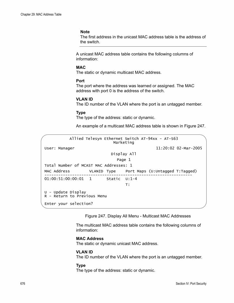
Chapter 29: MAC Address Table
NoteThe first address in the unicast MAC address table is the address of the switch.
A unicast MAC address table contains the following columns of information:
MAC The static or dynamic multicast MAC address.
PortThe port where the address was learned or assigned. The MAC address with port 0 is the address of the switch.
VLAN IDThe ID number of the VLAN where the port is an untagged member.
TypeThe type of the address: static or dynamic.
An example of a multicast MAC address table is shown in Figure 247.
Figure 247. Display All Menu - Multicast MAC Addresses
The multicast MAC address table contains the following columns of information:
MAC AddressThe static or dynamic unicast MAC address.
VLAN IDThe ID number of the VLAN where the port is an untagged member.
TypeThe type of the address: static or dynamic.
Allied Telesyn Ethernet Switch AT-94xx - AT-S63Marketing
User: Manager 11:20:02 02-Mar-2005
Display All
Page 1
Total Number of MCAST MAC Addresses: 1
MAC Address VLANID Type Port Maps (U:Untagged T:Tagged)----------------------------------------------------------------01:00:51:00:00:01 1 Static U:1-4
T:
U - Update DisplayR - Return to Previous Menu
Enter your selection?
676 Section IV: Port Security
AT-S63 Management Software Menus Interface User’s Guide
Port MapsThe tagged and untagged ports on the switch that are members of a multicast group. This column is useful in determining which ports belong to different groups.
The other selections on the menu are:
2 - Display StaticThis selection displays only the static addresses assigned to the ports on the switch.
3 - Display DynamicThis selection displays only the dynamic addresses learned on the ports on the switch.
4 - Display by PortThis selection displays the dynamic and static MAC addresses of a particular port. When you select this option, you are prompted for a port number. You can specify more than one port at a time.
5 - Display Specified MACThis selection displays the port number on which a MAC address was assigned or learned.
If you want to know on which port a particular MAC address was learned, you can display the MAC address table and scroll through the list looking for the MAC address. But if the switch is part of a large network, finding the address could prove difficult.
When you use the Display Specified MAC selection, you specify the MAC address and the AT-S63 management software automatically locates the port on the switch where the device is connected.
6 - Display by VLAN IDDisplays all the static and dynamic addresses learned on the tagged and untagged ports of a specific VLAN. When you select this option, you are prompted for the VLAN ID number of the VLAN. You can specify only one VLAN at a time
7 - Display on Base PortsThis selection displays the static and dynamic MAC addresses learned on the base ports on the AT-9400 Series switch. It does not display any addresses assigned or learned on any uplink ports.
Section IV: Port Security 677
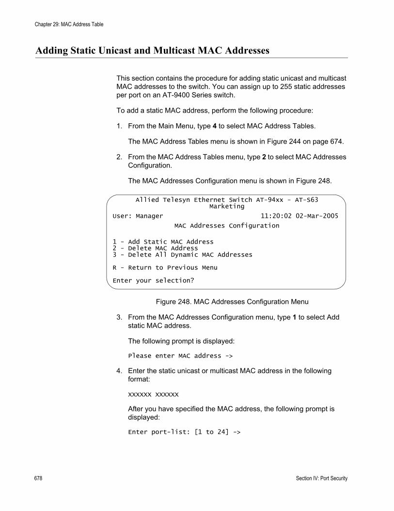
Chapter 29: MAC Address Table
Adding Static Unicast and Multicast MAC Addresses
This section contains the procedure for adding static unicast and multicast MAC addresses to the switch. You can assign up to 255 static addresses per port on an AT-9400 Series switch.
To add a static MAC address, perform the following procedure:
1. From the Main Menu, type 4 to select MAC Address Tables.
The MAC Address Tables menu is shown in Figure 244 on page 674.
2. From the MAC Address Tables menu, type 2 to select MAC Addresses Configuration.
The MAC Addresses Configuration menu is shown in Figure 248.
Figure 248. MAC Addresses Configuration Menu
3. From the MAC Addresses Configuration menu, type 1 to select Add static MAC address.
The following prompt is displayed:
Please enter MAC address ->
4. Enter the static unicast or multicast MAC address in the following format:
XXXXXX XXXXXX
After you have specified the MAC address, the following prompt is displayed:
Enter port-list: [1 to 24] ->
Allied Telesyn Ethernet Switch AT-94xx - AT-S63Marketing
User: Manager 11:20:02 02-Mar-2005
MAC Addresses Configuration
1 - Add Static MAC Address2 - Delete MAC Address3 - Delete All Dynamic MAC Addresses
R - Return to Previous Menu
Enter your selection?
678 Section IV: Port Security
AT-S63 Management Software Menus Interface User’s Guide
5. Enter the number of the port on the switch where you want to assign the static address. If you are adding a static unicast address, you can specify only one port.
If you are entering a static multicast address, you must specify the port when the multicast application is located as well as the ports where the host nodes are connected. Assigning the address only to the port where the multicast application is located will result in the failure of the multicast packets to be properly forwarded to the host nodes. You can specify the ports individually (e.g., 1,4,5), as a range (e.g., 11-14) or both (e.g., 15-17,22,24).
The following prompt is displayed:
Please enter VLAN ID: [1 to 4094] -> 1
6. Enter the VLAN ID where the port is a member.
7. Repeat this procedure starting with Step 3 to enter additional static unicast or multicast MAC addresses.
Section IV: Port Security 679
Chapter 29: MAC Address Table
Deleting Unicast and Multicast MAC Addresses
To delete a dynamic or static unicast or multicast address from the MAC address table, perform the following procedure:
1. From the Main Menu, type 4 to select MAC Address Tables.
The MAC Address Tables menu is shown in Figure 244 on page 674.
2. From the MAC Address Tables menu, type 2 to select MAC Addresses Configuration.
The MAC Addresses Configuration menu is shown in Figure 248 on page 678.
3. From the MAC Addresses Configuration menu, type 2 to select Delete MAC Address.
The following prompt is displayed:
Please enter a MAC address ->
4. Enter the unicast or multicast MAC address to be deleted in the following format:
XXXXXX XXXXXX
After you have entered the MAC address, the following prompt is displayed:
Please enter VLAN ID -> [1 to 4094] -> 1
5. Enter the VLAN ID of the port where the address was assigned or learned.
The MAC address is deleted from the switch’s MAC address table.
NoteYou cannot delete a switch’s MAC address, an STP BPDU MAC address, or a broadcast address.
6. Repeat the procedure to delete additional MAC addresses.
7. After making changes, type R until you return to the Main Menu. Then type S to select Save Configuration Changes.
680 Section IV: Port Security

AT-S63 Management Software Menus Interface User’s Guide
Deleting All Dynamic MAC Addresses
To delete all dynamic unicast and multicast MAC address from the MAC address table, perform the following procedure:
1. From the Main Menu, type 4 to select MAC Address Tables.
The MAC Address Tables menu is shown in Figure 244 on page 674.
2. From the MAC Address Tables menu, type 2 to select MAC Addresses Configuration.
The MAC Addresses Configuration menu is shown in Figure 248 on page 678.
3. From the MAC Addresses Configuration menu, type 3 to select Delete All Dynamic MAC Addresses.
The following prompt is displayed:
All learned MAC (non-static) addresses will be deletedDo you want to continue? [Yes/No] ->
4. Type Y to delete the addresses or N to cancel the procedure.
If you respond with yes, all dynamic unicast and multicast addresses are deleted from the table, and the switch begins to learn new addresses.
Section IV: Port Security 681
Chapter 29: MAC Address Table
Changing the Aging Time
The switch uses the aging time to delete inactive dynamic MAC addresses from the MAC address table. When the switch detects that no packets have been sent to or received from a particular MAC address in the table after the period specified by the aging time, the switch deletes the address. This prevents the table from becoming full of addresses of nodes that are no longer active.
The default setting for the aging time is 300 seconds (5 minutes).
To adjust the aging time, perform the following procedure:
1. From the Main Menu, type 4 to select MAC Address Tables.
The MAC Address Tables menu is shown in Figure 244 on page 674.
2. From the MAC Address Tables menu, type 1 to select MAC Address Aging Time.
The following prompt is displayed:
Enter MAC address aging time -> [8 to 512]
3. Enter a new value in seconds.
The range is 8 to 512 seconds. The default is 300 seconds (5 minutes).
The new value is immediately activated on the switch.
4. After making changes, type R until you return to the Main Menu. Then type S to select Save Configuration Changes.
682 Section IV: Port Security
Section VII
Management Security
The chapters in this section provide information and procedures for basic switch setup using the AT-S63 management software. The chapters include:
Chapter 30, “Web Server” on page 685Chapter 31, “Encryption Keys” on page 693Chapter 32, “PKI Certificates and SSL” on page 719Chapter 33, “Secure Shell (SSH)” on page 751Chapter 34, “TACACS+ and RADIUS Protocols” on page 761Chapter 35, “Management Access Control Lists” on page 775
Section VII: Management Security 683

684 Section VII: Management Security

Chapter 30
Web Server
The chapter provides an overview of the web server feature and procedures to configure the server. It contains the following sections:
“Web Server Overview” on page 686“Configuring the Web Server” on page 687“General Steps for Configuring the Web Server for Encryption” on page 690
Section VII: Management Security 685
Chapter 30: Web Server
Web Server Overview
The AT-S63 management software is shipped with web server software. The software is available so that you can remotely manage the switch with a web browser from any management station on your network. (The instructions for managing a switch with a web browser are described in the AT-S63 Network Management Web Browser Interface User’s Guide.)
The web server can operate in two modes. The first is referred to as non-secure HTTP mode. In this mode, packets sent between the switch and the web browser during a management session are transmitted in plaintext. Anyone monitoring your network with a sniffer can view the contents of the management packets.
The web server can also operate in the secure HTTPS mode where all communications between the switch and a web browser are encrypted. This feature uses the Secure Sockets Layer (SSL) protocol. It can help protect your switch from intruders who might be monitoring your network.
If you intend to use the secure HTTPS mode of the web server, there are several procedures you need to perform before you can configure the web server. You must create an encryption key, as explained in Chapter 31, “Encryption Keys” on page 693. You must also create a certificate and add the certificate to the certificate database. This latter part is explained in Chapter 32, “PKI Certificates and SSL” on page 719.
The default setting for the web server is enabled, with the non-secure HTTP mode as the default active mode.
NoteTo use SSL in an enhanced stack, all switches in the stack must use SSL. For further information, refer to “SSL and Enhanced Stacking” on page 695.
SupportedProtocols
The switch supports the following HTTP and HTTPs protocols:
HTTP v1.0 and v1.1 protocolsHTTPS v1.0 and v1.1 protocols running over SSL
The switch supports the following SSL protocols:
SSL version 2.0SSL version 3.0TLS (Transmission Layer Security) version 1.0
686 Section VII: Management Security
AT-S63 Management Software Menus Interface User’s Guide
Configuring the Web Server
This procedure explains how to enable and disable the web server and how to configure the HTTP and HTTPS settings from a local or Telnet management session. The default setting for the web server is enabled, with the non-secure HTTP mode as the active web server mode.
Before you configure the web server, please note the following:
You cannot make any changes to the HTTP or HTTPS settings while the web server is enabled. You must first disable the web server before making changes.To configure the web server for the HTTPS secure mode, you must first create an encryption key and a certificate, and add the certificate to the certificate database. The AT-S63 management software does not allow you to configure the web server for the HTTPS secure mode until those steps have been completed. For instructions, refer to Chapter 31, “Encryption Keys” on page 693, and Chapter 32, “PKI Certificates and SSL” on page 719.To make a change to an HTTP or HTTPS setting, you must perform the entire procedure. For example, to change the port number for HTTP, you must first disable the web server and then reselect HTTP.
To configure the web server, perform the following procedure:
1. From the Main Menu, type 5 to select System Administration.
The System Administration menu is shown in Figure 4 on page 46.
2. From the System Administration menu, type 4 to select Web Server Configuration.
Section VII: Management Security 687
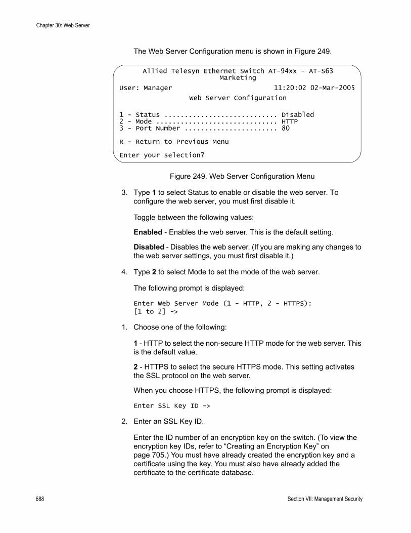
Chapter 30: Web Server
The Web Server Configuration menu is shown in Figure 249.
Figure 249. Web Server Configuration Menu
3. Type 1 to select Status to enable or disable the web server. To configure the web server, you must first disable it.
Toggle between the following values:
Enabled - Enables the web server. This is the default setting.
Disabled - Disables the web server. (If you are making any changes to the web server settings, you must first disable it.)
4. Type 2 to select Mode to set the mode of the web server.
The following prompt is displayed:
Enter Web Server Mode (1 - HTTP, 2 - HTTPS): [1 to 2] ->
1. Choose one of the following:
1 - HTTP to select the non-secure HTTP mode for the web server. This is the default value.
2 - HTTPS to select the secure HTTPS mode. This setting activates the SSL protocol on the web server.
When you choose HTTPS, the following prompt is displayed:
Enter SSL Key ID ->
2. Enter an SSL Key ID.
Enter the ID number of an encryption key on the switch. (To view the encryption key IDs, refer to “Creating an Encryption Key” on page 705.) You must have already created the encryption key and a certificate using the key. You must also have already added the certificate to the certificate database.
Allied Telesyn Ethernet Switch AT-94xx - AT-S63Marketing
User: Manager 11:20:02 02-Mar-2005
Web Server Configuration
1 - Status ............................ Disabled2 - Mode .............................. HTTP3 - Port Number ....................... 80
R - Return to Previous Menu
Enter your selection?
688 Section VII: Management Security
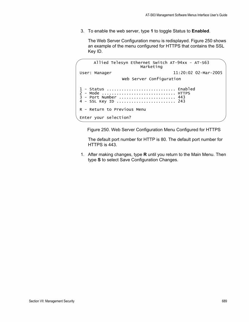
AT-S63 Management Software Menus Interface User’s Guide
3. To enable the web server, type 1 to toggle Status to Enabled.
The Web Server Configuration menu is redisplayed. Figure 250 shows an example of the menu configured for HTTPS that contains the SSL Key ID.
Figure 250. Web Server Configuration Menu Configured for HTTPS
The default port number for HTTP is 80. The default port number for HTTPS is 443.
1. After making changes, type R until you return to the Main Menu. Then type S to select Save Configuration Changes.
Allied Telesyn Ethernet Switch AT-94xx - AT-S63Marketing
User: Manager 11:20:02 02-Mar-2005
Web Server Configuration
1 - Status ............................ Enabled2 - Mode .............................. HTTPS3 - Port Number ....................... 4434 - SSL Key ID ........................ 243
R - Return to Previous Menu
Enter your selection?
Section VII: Management Security 689

Chapter 30: Web Server
General Steps for Configuring the Web Server for Encryption
There are several procedures you need to perform in order to implement HTTPS and web browser encryption on the switch. This section is here to provide you with the general steps that you need to do to and the procedures for performing them. There is a section for configuring the web server with a self-signed certificate and another for a public or private CA certificate.
General Steps fora Self-signed
Certificate
Below are the general steps for setting up the web server with a self-signed certificate.
1. Set the switch’s date and time. You must do this before you create a certificate because the date and time are stamped in the digital document. For instructions, refer to “Setting the System Time” on page 58.
2. Create a public and private key pair, as explained in “Creating an Encryption Key” on page 705.
3. Create a self-signed certificate using the key pair, as explained in “Creating a Self-signed Certificate” on page 729.
4. Add the certificate to the certificate database, as explained in “Adding a Certificate to the Database” on page 733.
5. Configure the web server on the switch by activating HTTPS and specifying the key pair used to create the certificate as the active key. This step is explained in “Configuring the Web Server” on page 687.
General Steps fora Public orPrivate CACertificate
Below are the steps for setting up the web server with a public or private CA certificate. This requires generating an enrollment request.
1. Set the switch’s date and time. You must do this before you create the enrollment request. The date and time at stamped in the request. The instructions for this are in “Setting the System Time” on page 58.
2. Create a key pair, as explained in “Creating an Encryption Key” on page 705.
3. Generate an enrollment request, as explained in “Generating an Enrollment Request” on page 744.
4. Upload the enrollment request from the AT-S63 file system onto your management station or a TFTP server, as explained in “Uploading a System File” on page 222.
5. Submit the enrollment request to the public or private CA.
690 Section VII: Management Security
AT-S63 Management Software Menus Interface User’s Guide
6. After you have received the appropriate certificates back from the CA, download them into the AT-S63 file system from your management station or a TFTP server, as explained in “Downloading a System File” on page 216.
7. Add the certificates to the certificate database, as explained in “Adding a Certificate to the Database” on page 733.
8. Configure the web server on the switch by activating HTTPS and specifying the key pair used to create the enrollment request as the active key. This step is explained in “Configuring the Web Server” on page 687.
Section VII: Management Security 691

Chapter 30: Web Server
692 Section VII: Management Security
Chapter 31
Encryption Keys
This chapter describes encryption keys and how you can use keys to improve the security of your switches. Because of the complexity of the feature, this chapter contains several overview sections. The Basic Overview section offers a general review of the purpose of this feature along with relevant guidelines. For additional information, refer to the two Technical Overview sections. The sections in this chapter include:
“Basic Overview” on page 694“Technical Overview of Secure Sockets Layer” on page 697“Technical Overview of Encryption” on page 700“Creating an Encryption Key” on page 705“Deleting an Encryption Key” on page 709“Modifying an Encryption Key” on page 710“Exporting an Encryption Key” on page 711“Importing an Encryption Key” on page 714“Displaying the Encryption Keys” on page 717
NoteThis feature is only supported in the version of AT-S63 management software that features the Secure Sockets Layer (SSL) protocol and Public Key Infrastructure (PKI).
For an overview of the procedures to configuring the switch’s web server for encryption, refer to “General Steps for Configuring the Web Server for Encryption” on page 690.
Section VII: Management Security 693
Chapter 31: Encryption Keys
Basic Overview
Protecting your managed switches from unauthorized management access is an important role for a network manager. Network operations and security can be severely compromised if an intruder gains access to critical switch information, such as a manager’s login username and password, and uses that information to alter a switch’s configuration settings.
One way an intruder could covertly obtain critical switch information is by monitoring network traffic with a network analyzer, such as a sniffer, and capturing management packets from remote Telnet or web browser management sessions. The payload in the packets exchanged during remote management sessions is transmitted in plaintext, which can be easily deciphered. The information obtained from the management packets could enable an intruder to access a switch.
A way to prevent this type assault is by encrypting the payload in the packets exchanged during a remote management session between a management station and a switch. Encryption makes the packets unintelligible to an outside agent. Only the remote workstation and the switch engaged in the management session are able to decode each other’s packets.
The fundamental part of encryption is the encryption key. The key converts plaintext into encrypted text, and back again. A key consists of two separate keys: a private key and a public key. Together they create a key pair.
The AT-S63 management software supports encryption for remote web browser management sessions using the Secure Sockets Layer (SSL) protocol. Adding encryption to your web browser management sessions involves creating one key pair and adding the public key of the key pair to a certificate, a digital document stored on the switch. You can have the switch create the certificate itself or you can have a public or private certificate authority (CA) create it for you. For an overview of the steps for adding encryption to your web browser management sessions, refer to “General Steps for Configuring the Web Server for Encryption” on page 690.
The Telnet protocol does not support encryption. To have encryption when you remotely manage a switch using the menus interface, you must first obtain a Secure Shell (SSH) protocol application. SSH offers the same function as Telnet, but with encryption.
SSH encryption requires that you create two key pairs on the switch— a server key pair and a host key pair and then configure the Secure Shell protocol server software on the switch, as explained in Chapter 33, “Secure Shell (SSH)” on page 751.
694 Section VII: Management Security
AT-S63 Management Software Menus Interface User’s Guide
Encryption KeyLength
To create a key pair, you must specify its length. The length is given in bits. The range is 512 to 1,536 bits, in increments of 256 bits. The default is 512 bits.
The general rule on key lengths is that the longer the key, the more difficult it is for someone to break (decipher). So if you are particularly concerned about the safety of your management sessions, use a longer key length than the default, although the default will be more than sufficient.
Creating a key is a very CPU intensive operation for the switch. The switch does not stop forwarding packets between the ports, but the process can impact the CPU’s handling of network events, such as the processing of spanning tree BPDU packets. This can result in unexpected and unwanted switch behavior.
A key with the default length should take the switch less than a minute to create. Longer keys can take up to 15 minutes. Consider this information when you create a key so that you do not to impact the operations of your network. If you want a longer key, consider creating it before you connect the switch to the network, or during periods of low network traffic.
Encryption KeyGuidelines
Below are guidelines to observe when creating an encryption key pair:
Web browser encryption requires only one key pair.SSH encryption requires two key pairs. The keys must be of different lengths of at least one increment (256 bits) apart. The recommended size for the server key is 768 bits and the recommended size for the host key is 1024 bits.An AT-9400 Series switch can only use those key pairs it has generated itself. The switch cannot use a key created on another system and imported onto the switch.The AT-S63 management software does not allow you to copy or export a private key from a switch. However, you can export a public key.The AT-S63 management software uses the RSA public key algorithm.Web browser and SSH encryption can share a key pair.
SSL andEnhanced
Stacking
Secure Sockets Layer (SSL) is supported in an enhanced stack, but only when all switches in the stack are using the feature.
When a switch’s web server is operating in HTTP, management packets are transmitted in plaintext. When it operates in HTTPS, management packets are sent encrypted. The web server on an AT-9400 Series switch, can operate in either mode. Enhanced stacking switches that do not support SSL, such as the AT-8000 Series switches, use HTTP exclusively.
A web browser management session of the switches in an enhanced stack cannot alternate between the different security modes during a session.
Section VII: Management Security 695
Chapter 31: Encryption Keys
The management session assumes that the web server mode that the master switch is using is the same for all the switches in the stack. As an example, if the master switch is using HTTPS, a web browser management session assumes that all the other switches in the stack are also using HTTPS, and it does not allow you to manage any switches running HTTP.
For those networks that consist of enhanced stacking switches where some switches support SSL and others do not, there are two approaches you can take. One is to create different enhanced stacks for the different switches. You could create one enhanced stack for those switches that support SSL and another stack for those that do not. You create different enhanced stacks by assigning switches to different Management VLANs. For information, refer to “Specifying a Management VLAN” on page 581.
Another workaround is to leave the switches in one enhanced stack, but designate two master switches. One master switch could be using HTTP and the other HTTPS. When you want to use your web browser to manage those switches that support SSL, you would start the management session on the master switch whose server mode is set to HTTPS. To manage those switch not supporting SSL, you would start the management session on the master switch whose web server is set to HTTP.
To implement SSL in an enhanced stack, you must create an encryption key pair and a certificate on each switch. When you start a web browser management session on the master switch of an enhanced stack, the management session uses the certificate and key pair on the master switch. When you change to another switch in the stack, the management session starts to use the certificate and key pair on that switch, and so forth.
696 Section VII: Management Security
AT-S63 Management Software Menus Interface User’s Guide
Technical Overview of Secure Sockets Layer
This section describes the Secure Sockets Layer (SSL) feature, a security protocol that provides a secure and private TCP connection between a client and server.
SSL can be used with many higher layer protocols including HTTP, File Transfer Protocol (FTP) and Net News Transfer Protocol (NNTP). Most web browsers and servers support SSL, and its most common deployment is for secure connections between a client and server over the Internet.
The switch supports SSL versions 2.0 (client hello only) and 3.0 which were developed by Netscape, and the Internet Engineering Task Force (IETF) standard for SSL, known as SSL version 3.1 or Transport Layer Security (TLS).
Within the Ethernet protocol stack, SSL is a Layer 4 protocol that is in between the HTTP and TCP protocol layers. HTTP communicates with SSL in the same way as with TCP. In other words, TCP processes SSL requests like any other protocol requesting its services.
SSL provides a secure connection over which web pages can be accessed from an HTTP server. The operation of SSL is transparent to the end user who is accessing a web site with the following exceptions:
The site’s URL changes from HTTP to HTTPS.The browser indicates that it is a secured connection by displaying an icon, such as a padlock icon.
By default, HTTP and HTTPS use the separate well-known ports 80 and 443, respectively. Secure connections over the Internet are important when transmitting confidential data such as credit card details or passwords. SSL allows the client to verify the server’s identity before either side sends any sensitive information. SSL also prevents a third party from interfering with the message because only trusted devices have access to the unprotected data.
SSL Encryption SSL uses encryption to ensure the security of data transmission. Encryption is a process that uses an algorithm to encode data so it can only be accessed by a trusted device. An encrypted message remains confidential.
All application data messages are authenticated by SSL with a message authentication code (MAC). The MAC is a checksum that is created by the sender and is sent as part of the encrypted message. The recipient re-calculates the MAC, and if the values match, the sender’s identity is verified. The MAC also ensures that the message has not been tampered with by a third party because any change to the message changes the
Section VII: Management Security 697

Chapter 31: Encryption Keys
MAC.
SSL uses asymmetrical (Public Key) encryption to establish a connection between client and server, and symmetrical (Secret Key) encryption for the data transfer phase.
User Verification An SSL connection has two phases: handshake and data transfer. The handshake initiates the SSL session, during which data is securely transmitted between a client and server. During the handshake, the following occurs:
The client and server establish the SSL version they are to use. The client and server negotiate the cipher suite for the session, which includes encryption, authentication, and key exchange algorithms.The symmetrical key is exchanged.The client authenticates the server (optionally, the server authenticates the client).
SSL messages are encapsulated by the Record Layer before being passed to TCP for transmission. Four types of SSL messages exist, they are:
HandshakeChange Cipher SpecAlertApplication data (HTTP, FTP or NNTP)
As discussed previously, the Handshake message initiates the SSL session.
The Change Cipher Spec message informs the receiving party that all subsequent messages are encrypted using previously negotiated security options. The parties use the strongest cryptographic systems that they both support.
The Alert message is used if the client or server detects an error. Alert messages also inform the other end that the session is about to close. In addition, the Alert message contains a severity rating and a description of the alert. For example, an alert message is sent if either party receives an invalid certificate or an unexpected message.
The Application data message encapsulates the encrypted application data.
Authentication Authentication is the process of ensuring that both the web site and the end user are genuine. In other words, they are not imposters. Both the server and an individual users need to be authenticated. This is especially important when transmitting secure data over the Internet.
698 Section VII: Management Security

AT-S63 Management Software Menus Interface User’s Guide
To verify the authenticity of a server, the server has a public and private key. The public key is given to the user.
SSL uses certificates for authentication. A certificate binds a public key to a server name. A certification authority (CA) issues certificates after checking that a public key belongs to its claimed owner. There are several agencies that are trusted to issue certificates. Individual browsers have approved Root CAs that are built in to the browser.
Section VII: Management Security 699
Chapter 31: Encryption Keys
Technical Overview of Encryption
The encryption feature provides the following data security services:
Data encryptionData authenticationKey exchange algorithms Key creation and storage
Data Encryption Data encryption for switches is driven by the need for organizations to keep sensitive data private and secure. Data encryption operates by applying an encryption algorithm and key to the original data (the plaintext) to convert it into an encrypted form (the ciphertext). The ciphertext produced by encryption is a function of the algorithm used and the key. Because it is easy to discover what type of algorithm is being used, the security of an encryption system relies on the secrecy of its key information. When the ciphertext is received by the remote router, the decryption algorithm and key are used to recover the original plaintext. Often, a checksum is added to the data before encryption. The checksum allows the validity of the data to be checked on decryption.
There are two main classes of encryption algorithm in use: symmetrical encryption and asymmetrical encryption.
Symmetrical Encryption
Symmetrical encryption refers to algorithms in which a single key is used for both the encryption and decryption processes. Anyone who has access to the key used to encrypt the plaintext can decrypt the ciphertext. Because the encryption key must be kept secret to protect the data, these algorithms are also called private, or secret key algorithms. The key can be any value of the appropriate length.
DES Encryption Algorithms
The most common symmetrical encryption system is the Data Encryption Standard (DES) algorithm (FIPS PUB 46). The DES algorithm has withstood the test of time and proved itself to be a highly secure encryption algorithm. To fully conform to the DES standard, the actual data encryption operations must be carried out in hardware. Software implementations can only be DES-compatible, not DES-compliant. The DES algorithm has a key length of 56 bits and operates on 64-bit blocks of data. DES can be used in the following modes:
Electronic Code Book (ECB) is the fundamental DES function. Plaintext is divided into 64-bit blocks which are encrypted with the DES
700 Section VII: Management Security

AT-S63 Management Software Menus Interface User’s Guide
algorithm and key. For a given input block of plaintext ECB always produces the same block of ciphertext.Cipher Block Chaining (CBC) is the most popular form of DES encryption. CBC also operates on 64-bit blocks of data, but includes a feedback step which chains consecutive blocks so that repetitive plaintext data, such as ASCII blanks, does not yield identical ciphertext. CBC also introduces a dependency between data blocks which protects against fraudulent data insertion and replay attacks. The feedback for the first block of data is provided by a 64-bit Initialization Vector (IV). This is the DES mode used for the switch’s data encryption process.Cipher FeedBack (CFB) is an additive-stream-cipher method which uses DES to generate a pseudo-random binary stream that is combined with the plaintext to produce the ciphertext. The ciphertext is then fed back to form a portion of the next DES input block.Output FeedBack (OFB) combines the first IV DES algorithms with the plaintext to form ciphertext. The ciphertext is then used as the next IV.
The DES algorithm has been optimized to produce very high speed hardware implementations, making it ideal for networks where high throughput and low latency are essential.
Triple DES Encryption Algorithms
The Triple DES (3DES) encryption algorithm is a simple variant on the DES CBC algorithm. The DES function is replaced by three rounds of that function, an encryption followed by a decryption followed by an encryption. This can be done by using either two DES keys (112-bit key) or three DES keys (168-bit key).
The two-key algorithm encrypts the data with the first key, decrypts it with the second key and then encrypts the data again with the first key. The three-key algorithm uses a different key for each step. The three-key algorithm is the most secure algorithm due to the long key length.
There are several modes in which Triple DES encryption can be performed. The two most common modes are:
Inner CBC mode encrypts the entire packet in CBC mode three times and requires three different initial is at ion vectors (IV’s).Outer CBC mode triple encrypts each 8-byte block of a packet in CBC mode three times and requires one IV.
Asymmetrical (Public Key) Encryption
Asymmetrical encryption algorithms use two keys—one for encryption and one for decryption. The encryption key is called the public key because it cannot be used to decrypt a message and therefore does not need be kept
Section VII: Management Security 701

Chapter 31: Encryption Keys
secret. Only the decryption, or private key, needs to be kept secret. The other name for this type of algorithm is public key encryption. The public and private key pair cannot be randomly assigned, but must be generated together. In a typical scenario, a decryption station generates a key pair and then distributes the public key to encrypting stations. This distribution does not need to be kept secret, but it must be protected against the substitution of the public key by a malicious third party. Another use for asymmetrical encryption is as a digital signature. The signature station publishes its public key, and then signs its messages by encrypting them with its private key. To verify the source of a message, the receiver decrypts the messages with the published public key. If the message that results is valid, then the signing station is authenticated as the source of the message.
The most common asymmetrical encryption algorithm is RSA. This algorithm uses mathematical operations which are relatively easy to calculate in one direction, but which have no known reverse solution. The security of RSA relies on the difficulty of factoring the modulus of the RSA key. Because key lengths of 512 bits or greater are used in public key encryption systems, decrypting RSA encrypted messages is almost impossible using current technology. The AT-S63 management software uses the RSA algorithm.
Asymmetrical encryption algorithms require enormous computational resources, making them very slow when compared to symmetrical algorithms. For this reason they are normally only used on small blocks of data (for example, exchanging symmetrical algorithm keys), and not for entire data streams.
DataAuthentication
Data authentication for switches is driven by the need for organizations to verify that sensitive data has not been altered.
Data authentication operates by calculating a message authentication code (MAC), commonly referred to as a hash, of the original data and appending it to the message. The MAC produced is a function of the algorithm used and the key. Because it is easy to discover what type of algorithm is being used, the security of an authentication system relies on the secrecy of its key information. When the message is received by the remote switch, another MAC is calculated and checked against the MAC appended to the message. If the two MACs are identical, the message is authentic.
Typically a MAC is calculated using a keyed one-way hash algorithm. A keyed one-way hash function operates on an arbitrary-length message and a key. It returns a fixed length hash. The properties which make the hash function one-way are:
It is easy to calculate the hash from the message and the keyIt is very hard to compute the message and the key from the hash
702 Section VII: Management Security

AT-S63 Management Software Menus Interface User’s Guide
It is very hard to find another message and key which give the same hash
The two most commonly used one-way hash algorithms are MD5 (Message Digest 5, defined in RFC 1321) and SHA-1 (Secure Hash Algorithm, defined in FIPS-180-1). MD5 returns a 128-bit hash and SHA-1 returns a 160-bit hash. MD5 is faster in software than SHA-1, but SHA-1 is generally regarded to be slightly more secure.
HMAC is a mechanism for calculating a keyed Message Authentication Code which can use any one-way hash function. It allows for keys to be handled the same way for all hash functions and it allows for different sized hashes to be returned.
Another method of calculating a MAC is to use a symmetric block cypher such as DES in CBC mode. This is done by encrypting the message and using the last encrypted block as the MAC and appending this to the original message (plain-text). Using CBC mode ensures that the whole message affects the resulting MAC.
Key ExchangeAlgorithms
Key exchange algorithms are used by switches to securely generate and exchange encryption and authentication keys with other switches. Without key exchange algorithms, encryption and authentication session keys must be manually changed by the system administrator. Often, it is not practical to change the session keys manually. Key exchange algorithms enable switches to re-generate session keys automatically and on a frequent basis.
The most important property of any key exchange algorithm is that only the negotiating parties are able to decode, or generate, the shared secret. Because of this requirement, public key cryptography plays an important role in key exchange algorithms. Public key cryptography provides a method of encrypting a message which can only be decrypted by one party. A switch can generate a session key, encrypt the key using public key cryptography, transmit the key over an insecure channel, and be certain that the key can only be decrypted by the intended recipient. Symmetrical encryption algorithms can also be used for key exchange, but commonly require an initial shared secret to be manually entered into all switches in the secure network.
The Diffie-Hellman algorithm, which is used by the AT-S63 management software, is one of the more commonly used key exchange algorithms. It is not an encryption algorithm because messages cannot be encrypted using Diffie-Hellman. Instead, it provides a method for two parties to generate the same shared secret with the knowledge that no other party can generate that same value. It uses public key cryptography and is commonly known as the first public key algorithm. Its security is based on the difficulty of solving the discrete logarithm problem, which can be compared to the difficulty of factoring very large integers.
Section VII: Management Security 703

Chapter 31: Encryption Keys
A Diffie-Hellman algorithm requires more processing overhead than RSA-based key exchange schemes, but it does not need the initial exchange of public keys. Instead, it uses published and well tested public key values. The security of the Diffie-Hellman algorithm depends on these values. Public key values less than 768 bits in length are considered to be insecure.
A Diffie-Hellman exchange starts with both parties generating a large random number. These values are kept secret, while the result of a public key operation on the random number is transmitted to the other party. A second public key operation, this time using the random number and the exchanged value, results in the shared secret. As long as no other party knows either of the random values, the secret is safe.
704 Section VII: Management Security
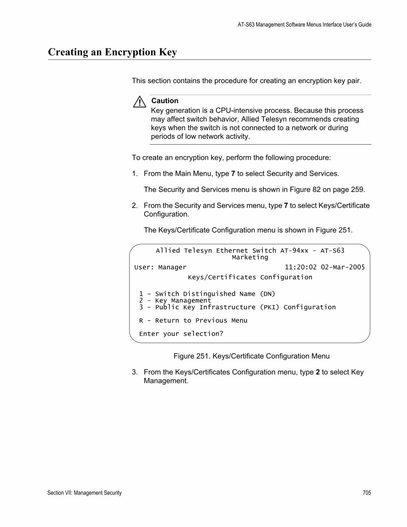
AT-S63 Management Software Menus Interface User’s Guide
Creating an Encryption Key
This section contains the procedure for creating an encryption key pair.
CautionKey generation is a CPU-intensive process. Because this process may affect switch behavior, Allied Telesyn recommends creating keys when the switch is not connected to a network or during periods of low network activity.
To create an encryption key, perform the following procedure:
1. From the Main Menu, type 7 to select Security and Services.
The Security and Services menu is shown in Figure 82 on page 259.
2. From the Security and Services menu, type 7 to select Keys/Certificate Configuration.
The Keys/Certificate Configuration menu is shown in Figure 251.
Figure 251. Keys/Certificate Configuration Menu
3. From the Keys/Certificates Configuration menu, type 2 to select Key Management.
Allied Telesyn Ethernet Switch AT-94xx - AT-S63Marketing
User: Manager 11:20:02 02-Mar-2005
Keys/Certificates Configuration
1 - Switch Distinguished Name (DN)2 - Key Management3 - Public Key Infrastructure (PKI) Configuration
R - Return to Previous Menu
Enter your selection?
Section VII: Management Security 705
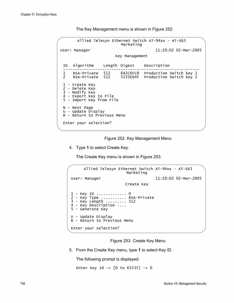
Chapter 31: Encryption Keys
The Key Management menu is shown in Figure 252.
Figure 252. Key Management Menu
4. Type 1 to select Create Key.
The Create Key menu is shown in Figure 253.
Figure 253. Create Key Menu
5. From the Create Key menu, type 1 to select Key ID.
The following prompt is displayed:
Enter Key Id -> [0 to 65535] -> 0
Allied Telesyn Ethernet Switch AT-94xx - AT-S63Marketing
User: Manager 11:20:02 02-Mar-2005
Key Management
ID Algorithm Length Digest Description-----------------------------------------------------------1 RSA-Private 512 642C6FC8 Production Switch key 12 RSA-Private 512 5333E64F Production Switch key 2
1 - Create Key2 - Delete Key3 - Modify Key4 - Export Key to File5 - Import Key from File
N - Next PageU - Update DisplayR - Return to Previous Menu
Enter your selection?
Allied Telesyn Ethernet Switch AT-94xx - AT-S63Marketing
User: Manager 11:20:02 02-Mar-2005
Create Key
1 - Key ID ............. 02 - Key Type ........... RSA-Private3 - Key Length ......... 5124 - Key Description .... 5 - Generate Key
U - Update DisplayR - Return to Previous Menu
Enter your selection?
706 Section VII: Management Security

AT-S63 Management Software Menus Interface User’s Guide
6. Enter an identification number for the key. This number can be from 0 to 65,535. This number is used only for identification purposes and not in generating the actual encryption key. The ID for each key on the switch must be unique.
NoteYou cannot change the value for option 2, Key Type. This value is always RSA - Private.
7. Type 3 to select Key Length.
The following prompt is displayed:
Enter Key Length ->[512 to 1536] -> 512
8. Enter a key length. The range is 512 to 1,536 bits, in increments of 256 bits (for example, 512, 768, 1024, etc). Before selecting a key length, note the following
For SSL and web browser encryption, key length can be any valid value within the range.For SSH host and server key pairs, the two keys must be created separately and be of different lengths of at least one increment (256 bits) apart. The recommended length for the server key is 768 bits and the recommended length for the host key is 1024 bits.
9. Type 4 to select Key Description.
The following prompt is displayed:
Enter new Description ->
10. Enter a description for the key. For instance, the description could reflect the name of the switch (for example, Production switch web server key). You can enter up to 40 alphanumeric values including spaces.
11. Type 5 to select Generate Key.
The following message is displayed:
Key generation will take some time. Please wait...
The AT-S63 management software begins to create the key. This process can take over a minute if you specified a long key length. After the key is created, you will see this message:
Press any key to continue ...
12. Press any key.
Section VII: Management Security 707
Chapter 31: Encryption Keys
The new key is added to the list of keys in the Key Management menu.
Returning to the Main Menu to save your changes is not necessary with this procedure. This type of change is automatically saved by the management software.
To create a self-signed certificate using the new encryption key, go to “Creating a Self-signed Certificate” on page 729. To create an enrollment request, go to “Generating an Enrollment Request” on page 744.
If you created server and host keys for SSH encryption, go to “Configuring SSH” on page 756 to configure the SSH server software on the switch.
708 Section VII: Management Security
AT-S63 Management Software Menus Interface User’s Guide
Deleting an Encryption Key
This section contains the procedure for deleting an encryption key pair from the switch. Note the following before performing this procedure.
Deleting a key pair from the key management database also deletes the key’s corresponding “.ukf” file from the AT-S63 file system.You cannot delete a key pair if it is being used by SSL or SSH. You must either disable the SSL or SSH server software or reconfigure the software by specifying another key.Deleting a key pair used in creating an SSL certificate voids the certificate.
To delete a public and private key pair, perform the following procedure:
1. From the Main Menu, type 7 to select Security and Services.
The Security and Services menu is shown in Figure 82 on page 259.
2. From the Security and Services menu, type 7 to select Keys/Certificate Configuration.
The Keys/Certificate Configuration menu is shown in Figure 251 on page 705.
3. From the Keys/Certificates Configuration menu, type 2 to select Key Management.
The Key Management menu is shown in Figure 252 on page 706.
4. From the Key Management menu, type 2 to select Delete Key.
The following prompt is displayed:
Enter Key Id to delete -> [0 to 65535] -> 0
5. Enter the ID number of the key you want to delete.
The key pair is deleted from the key database and its corresponding “.UKF” file is deleted from the file system.
Returning to the Main Menu to save your changes is not necessary with this procedure. This type of change is automatically saved by the management software.
Section VII: Management Security 709
Chapter 31: Encryption Keys
Modifying an Encryption Key
The Key Management menu has a selection for modifying the description of an encryption key. This is the only item of a key that you can modify. You cannot change a key’s ID, type, or length.
To change the description of a key, perform the following procedure:
1. From the Main Menu, type 7 to select Security and Services.
The Security and Services menu is shown in Figure 82 on page 259.
2. From the Security and Services menu, type 7 to select Keys/Certificate Configuration.
The Keys/Certificate Configuration menu is shown in Figure 251 on page 705.
3. From the Keys/Certificates Configuration menu, type 2 to select Key Management.
The Key Management menu is shown in Figure 252 on page 706.
4. From the Key Management menu, type, type 3 to select Modify Key.
The following prompt is displayed:
Enter Key Id to modify -> [0 to 65535] -> 0
5. Enter the ID of the key whose description you want to modify.
The following prompt is displayed.
Enter new Description ->
6. Enter the new description for the key. The description can be up to 40 alphanumeric characters including spaces. To help identify the key, you might make the description the name of the web server the key will be used to protect (for example, Production switch web server).
The following prompt is displayed:
Press any key to continue ...
The key has been modified.
7. Press any key to return to the Key Management menu.
Returning to the Main Menu to save your changes is not necessary with this procedure. This type of change is automatically saved by the management software.
710 Section VII: Management Security
AT-S63 Management Software Menus Interface User’s Guide
Exporting an Encryption Key
The following procedure exports the public key of a key pair into the AT-S62 file system. (The management software does not allow you to export a private key.) Before performing this procedure, please note the following:
The only circumstance in which you are likely to perform this procedure is if you are using an SSH client that does not download the key automatically when you start an SSH management session. In that situation, you can use this procedure to export the SSH client key from the key database into the AT-S62 file system, from where you can download it onto the SSH management session for incorporation in your SSH client software.You should not use this procedure to export an SSL public key. Typically, an SSL public key only has value when incorporated into a certificate or enrollment request.
To export a public key into the file system, perform the following procedure:
1. From the Main Menu, type 7 to select Security and Services.
The Security and Services menu is shown in Figure 82 on page 259.
2. From the Security and Services menu, type 7 to select Keys/Certificate Configuration.
The Keys/Certificate Configuration menu is shown in Figure 251 on page 705.
3. From the Keys/Certificates Configuration menu, type 2 to select Key Management.
The Key Management menu is shown in Figure 252 on page 706.
4. From the Key Management menu, type, type 4 to select Export Key to File.
Section VII: Management Security 711

Chapter 31: Encryption Keys
The Export Key to File menu is shown in Figure 254.
Figure 254. Export Key to File Menu
5. From the Export Key to File menu, type 1 to select Key ID.
The following prompt is displayed:
Enter Key ID -> [0 to 65535] ->
6. Enter the key ID of the public key you want to export into the file system.
NoteKey Type is a read-only field. You cannot change this value.
7. Type 3 to toggle Key File Format to specify the format of the key. Possible options are:
HEX - An internal format for storing files. Select this option for SSL configuration. This is the default.
SSH - A format for a Secure Shell (SSH) environment. Select this option for a SSH server or client.
8. Type 4 to select Key File Name.
The following prompt is displayed:
Enter filename (*.key) ->
9. Specify the file name of the key. The file name can be from one to eight alphanumeric characters, not including the extension. Spaces are allowed. The file name must include the extension “.key”.
10. Type 5 to select Export Key to File to export the key to a file.
Allied Telesyn Ethernet Switch AT-94xx - AT-S63Marketing
User: Manager 11:20:02 02-Mar-2005
Export Key to File
1 - Key ID ............ 02 - Key Type .......... RSA-Public3 - Key File Format ... HEX4 - Key File Name5 - Export Key to File
R - Return to Previous Menu
Enter your selection?
712 Section VII: Management Security

AT-S63 Management Software Menus Interface User’s Guide
The following message is displayed:
Key Export in Progress. Please wait...Done
11. Press any key to return to the Key Management menu.
To view the public key in the switch’s file system, refer to “Displaying System Files” on page 195.
Returning to the Main Menu to save your changes is not necessary with this procedure. This type of change is automatically saved by the management software.
Section VII: Management Security 713
Chapter 31: Encryption Keys
Importing an Encryption Key
Use the following procedure to import a public key from the AT-S62 file system into the key management database. If a file contains both public and private keys, only the public key is imported. The private key is ignored.
NoteIt is unlikely that you will ever need to perform this procedure for an SSL public key. A switch can only use those SSL public keys that it has generated itself.
This procedure starts from the Key Management menu. If you are unsure how to display the menu, perform steps 1 to 3 in “Creating an Encryption Key” on page 705.
To import a public key, perform the following procedure:
1. From the Main Menu, type 7 to select Security and Services.
The Security and Services menu is shown in Figure 82 on page 259.
2. From the Security and Services menu, type 7 to select Keys/Certificate Configuration.
The Keys/Certificate Configuration menu is shown in Figure 251 on page 705.
3. From the Keys/Certificates Configuration menu, type 2 to select Key Management.
The Key Management menu is shown in Figure 252 on page 706.
4. From the Key Management menu, type 5 to select Import Key From File to import an RSA - Public key.
714 Section VII: Management Security
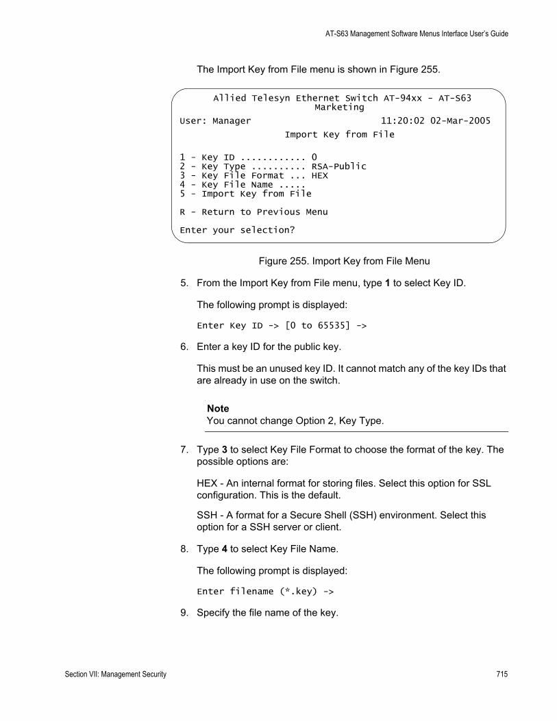
AT-S63 Management Software Menus Interface User’s Guide
The Import Key from File menu is shown in Figure 255.
Figure 255. Import Key from File Menu
5. From the Import Key from File menu, type 1 to select Key ID.
The following prompt is displayed:
Enter Key ID -> [0 to 65535] ->
6. Enter a key ID for the public key.
This must be an unused key ID. It cannot match any of the key IDs that are already in use on the switch.
NoteYou cannot change Option 2, Key Type.
7. Type 3 to select Key File Format to choose the format of the key. The possible options are:
HEX - An internal format for storing files. Select this option for SSL configuration. This is the default.
SSH - A format for a Secure Shell (SSH) environment. Select this option for a SSH server or client.
8. Type 4 to select Key File Name.
The following prompt is displayed:
Enter filename (*.key) ->
9. Specify the file name of the key.
Allied Telesyn Ethernet Switch AT-94xx - AT-S63Marketing
User: Manager 11:20:02 02-Mar-2005
Import Key from File
1 - Key ID ............ 02 - Key Type .......... RSA-Public3 - Key File Format ... HEX4 - Key File Name ..... 5 - Import Key from File
R - Return to Previous Menu
Enter your selection?
Section VII: Management Security 715
Chapter 31: Encryption Keys
The key file name must include the “.key” extension. If you are unsure of the file name, display the files in the switch’s file system by referring to “Displaying System Files” on page 195.
10. Type 5 to select Import Key From File to import a key to the switch from an external file.
The following message is displayed:
Key Import in Progress. Please wait...Done
After you receive this message, the key is added to the Key Management database. See the Key Management menu in Figure 252 on page 706.
Returning to the Main Menu to save your changes is not necessary with this procedure. This type of change is automatically saved by the management software.
716 Section VII: Management Security
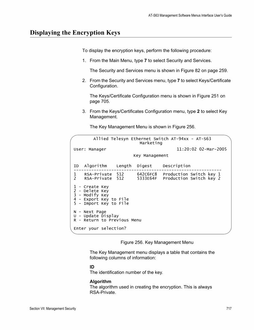
AT-S63 Management Software Menus Interface User’s Guide
Displaying the Encryption Keys
To display the encryption keys, perform the following procedure:
1. From the Main Menu, type 7 to select Security and Services.
The Security and Services menu is shown in Figure 82 on page 259.
2. From the Security and Services menu, type 7 to select Keys/Certificate Configuration.
The Keys/Certificate Configuration menu is shown in Figure 251 on page 705.
3. From the Keys/Certificates Configuration menu, type 2 to select Key Management.
The Key Management Menu is shown in Figure 256.
Figure 256. Key Management Menu
The Key Management menu displays a table that contains the following columns of information:
IDThe identification number of the key.
AlgorithmThe algorithm used in creating the encryption. This is alwaysRSA-Private.
Allied Telesyn Ethernet Switch AT-94xx - AT-S63Marketing
User: Manager 11:20:02 02-Mar-2005
Key Management
ID Algorithm Length Digest Description-----------------------------------------------------------1 RSA-Private 512 642C6FC8 Production Switch key 12 RSA-Private 512 5333E64F Production Switch key 2
1 - Create Key2 - Delete Key3 - Modify Key4 - Export Key to File5 - Import Key to File
N - Next PageU - Update DisplayR - Return to Previous Menu
Enter your selection?
Section VII: Management Security 717

Chapter 31: Encryption Keys
LengthThe length of the key in bits.
DigestThe CRC32 value of the MD5 digest of the public key.
DescriptionThe key’s description.
718 Section VII: Management Security
Chapter 32
PKI Certificates and SSL
This chapter contains the procedures for creating public key infrastructure (PKI) certificates for web server security. Because of the complexity of this feature, two overview sections are provided. The Basic Overview section offers a general review of the purpose of certificates along with relevant guidelines. For additional information refer to the Technical Overview section. This chapter contains the following sections:
“Basic Overview” on page 720“Technical Overview” on page 724“Creating a Self-signed Certificate” on page 729“Adding a Certificate to the Database” on page 733“Modifying a Certificate” on page 736“Deleting a Certificate” on page 739“Viewing a Certificate” on page 741“Generating an Enrollment Request” on page 744“Installing CA Certificates onto a Switch” on page 747“Viewing or Configuring the Number of Certificates in the Database” on page 748“Configuring SSL” on page 749
NoteThis feature is only supported on the version of AT-S63 management software that features secure sockets layer (SSL) and public key infrastructure (PKI).
Section VII: Management Security 719
Chapter 32: PKI Certificates and SSL
Basic Overview
This chapter describes the second part of the encryption feature of the AT-S63 management software—PKI certificates. The first part is explained in Chapter 31, “Encryption Keys” on page 693. Encryption keys and certificates allow you to encrypt the communications between your management station and a switch when you manage the device with a web browser. Encryption helps protect your switch from any intruder who might be using a sniffer to monitor the network.
Types ofCertificates
As explained in the previous chapter, an encryption key is used to encrypt the information in the frames that are exchanged between a switch and a web browser during a web browser management session.
An encryption key consists of two parts: a private key and a public key. The private key remains on the switch and is used by the device to encrypt its messages.
The public key is incorporated into a certificate. This is the key that your management station uses when you perform a web browser management session. Your web browser downloads the certificate from the switch when you begin a management session.
The quickest and easiest way to create a certificate is to have the switch create it itself. This type of certificate is called a self-signed certificate. If you have a small to medium sized network, then this might be the way to go. The procedure for creating this kind of certificate can be found in “Creating a Self-signed Certificate” on page 729. To review all the steps to configuring the web server for this type of certificate, refer to “General Steps for Configuring the Web Server for Encryption” on page 690.
Another option is to create the key but have someone else issue the certificate. That person, group, or organization is called a certification authority (CA).
There are two kinds of CAs: public and private. A public CA issues certificates for other companies and organizations. A prominent example of a public CA is VeriSign. A public CA requires proof of the identify of the company or organization that wants a certificate before it issues it.
Public CAs issue certificates that are typically intended for use by the general public. Because a certificate for an AT-9400 Series switch is used only by you and other network managers, you might decide that it is not necessary to have a public CA issue an AT-9400 Series switch certificate.
Some large companies have private CAs. This is a person or group within the company that is responsible for issuing certificates for the company’s network equipment. The value of a private CA is that the company can keep track of the certificates and control access to various network
720 Section VII: Management Security
AT-S63 Management Software Menus Interface User’s Guide
devices.
If your company is large enough, it might have a private CA and you might want that group to issue any AT-9400 Series switch certificates, if for no other reason than to follow company policy.
What is required to create a certificate by a public or private CA? First, you must create a key pair. After you have done that you need to generate an digital document called an enrollment request. The request contains the public key that you want the CA to use to create the certificate, along with other information.
Before you send an enrollment request to a CA, it is best to first contact the CA to determine what other documents or procedures might be required in order for the CA to create the certificate. This is particularly important with public CAs, which typically have strict guidelines on issuing certificates.
DistinguishedNames
Part of the task of creating a self-signed certificate or enrollment request is selecting a distinguished name. A distinguished name is integrated into a certificate along with the key. A distinguished name can have up to five parts. The parts are:
cn - common name
This can be the name of the person who will use the certificate.
ou - organizational unit
This is the name of a department, such as Network Support or IT.
o - organization
This is the name of the company.
st - state
This is the state.
c - country
This is the country
A certificate name does not need to contain all of these parts. You can use as many or as few as you want. You separate the parts with a comma. You can use alphanumeric characters, as well as spaces in the name strings. You cannot use quotation marks. To use the following special characters {=,+<>#;\<CR>}, type a “\” before the character.
Following are a few examples. This distinguished name contains only one part, the name of the switch:
cn=Production Switch
Section VII: Management Security 721
Chapter 32: PKI Certificates and SSL
This distinguished name omits the common name, but includes everything else:
ou=Network Support,o=XYZ Inc.,st=CA,c=US
So what would be a good distinguished name for a certificate for an AT-8524M switch? If the switch has an IP address, such as a master switch, you could use its address as the name. The following example is a distinguished name for a certificate for a master switch with the IP address 149.11.11.11:
cn=149.11.11.11
If your network has a Domain Name System and you mapped a name to the IP address of a switch, you can specify the switch’s name instead of the IP address as the distinguished name.
For those switches that do not have an IP address, such as slave switches, you could assign their certificates a distinguished name using the IP address of the master switch of the enhanced stack.
There is a benefit to giving a certificate a distinguished name equivalent to a master switch’s IP address or domain name. This relates to what happens when you start a web browser management session with a switch using SSL. The web browser on your management station checks to see if the name to whom the certificate was issued matches the name of the web site. In the case of a master or slave AT-9400 Series switch, the web site’s name is the master switch’s IP address or domain name. If the names do not match, the web browser displays a security warning. Of course, even if you see the security warning, you can close the warning prompt and still configure the switch using your web browser.
NoteIf the certificate will be issued by a private or public CA, you should check with the CA to see if they have any rules or guidelines on distinguished names for the certificates they issue.
722 Section VII: Management Security

AT-S63 Management Software Menus Interface User’s Guide
Guidelines The guidelines for creating certificates are:
A certificate can have only one key.A switch can use only those certificates that contain a key that was generated on the switch.You can create multiple certificates on a switch, but the device uses the certificate whose key pair has been designated as the active key pair for the switch’s web server.
Section VII: Management Security 723

Chapter 32: PKI Certificates and SSL
Technical Overview
The public key infrastructure (PKI) feature is part of the switch’s suite of security modules, and consists of a set of tools for managing and using certificates. The tools that make up the PKI allow the switch to securely exchange public keys, while being sure of the identity of the key holder.
The switch acts as an End Entity (EE) in a certificate-based PKI. More specifically, the switch can communicate with Certification Authorities (CAs) and Certificate Repositories to request, retrieve and verify certificates.The switch allows protocols running on the switch, such as ISAKMP, access to these certificates. The following sections of this chapter summarize these concepts and describe the switch’s implementation of them.
Public Keys Public key encryption involves the generation of two keys for each user, one private and one public. Material encrypted with a private key can only be decrypted with the corresponding public key, and vice versa. An individual’s private key must be kept secret, but the public key may be distributed as widely as desired, because it is impossible to calculate the private key from the public key. The advantage of public key encryption is that the private key need never be exchanged, and so can be kept secure more easily than a shared secret key.
MessageEncryption
One of the two main services provided by public key encryption is the exchange of encrypted messages. For example, user 1 can send a secure message to user 2 by encrypting it with user 2’s public key. Only user 2 can decrypt it, because only user 2 has access to the corresponding private key.
Digital Signatures The second main service provided by public key encryption is digital signing. Digital signatures both confirm the identity of the message’s supposed sender and protect the message from tampering. Therefore they provide message authentication and non-repudiation. It is very difficult for the signer of a message to claim that the message was corrupted, or to deny that it was sent.
Both the exchange of encrypted messages and digital signatures are secure only if the public key used for encryption or decryption belongs to the message’s expected recipient. If a public key is insecurely distributed, it is possible a malicious agent could intercept it and replace it with the malicious agent’s public key (the Man-in-the-Middle attack). To prevent this, and other attacks, PKI provides a means for secure transfer of public keys by linking an identity and that identity’s public key in a secure certificate.
724 Section VII: Management Security
AT-S63 Management Software Menus Interface User’s Guide
CautionAlthough a certificate binds a public key to a subject to ensure the public key’s security, it does not guarantee that the security of the associated private key has not been breached. A secure system is dependent upon private keys being kept secret, by protecting them from malicious physical and virtual access.
Certificates A certificate is an electronic identity document. To create a certificate for a subject, a trusted third party (known as the Certification Authority) verifies the subject’s identity, binds a public key to that identity, and digitally signs the certificate. A person receiving a copy of the certificate can verify the Certification Authority’s digital signature and be sure that the public key is owned by the identity in it.
The switch can generate a self-signed certificate but this should only be used with an SSL enabled HTTP server, or where third party trust is not required.
X.509 Certificates
The X.509 specification specifies a format for certificates. Almost all certificates use the X.509 version 3 format, described in RFC 2459, Internet X.509 Public Key Infrastructure Certificate and CRL Profile. This is the format which is supported by the switch.
An X.509 v3 certificate consists of:
A serial number, which distinguishes the certificate from all others issued by that issuer. This serial number is used to identify the certificate in a Certificate Revocation List, if necessary.The owner’s identity details, such as name, company and address.The owner’s public key, and information about the algorithm with which it was produced.The identity details of the organization which issued the certificate.The issuer’s digital signature and the algorithm used to produce it.The period for which the certificate is valid.Optional information is included, such as the type of application with which the certificate is intended to be used.
The issuing organization’s digital signature is included in order to authenticate the certificate. As a result, if a certificate is tampered with during transmission, the tampering is detected.
Section VII: Management Security 725
Chapter 32: PKI Certificates and SSL
Elements of aPublic Key
Infrastructure
A public key infrastructure is a set of applications which manage the creation, retrieval, validation and storage of certificates. A PKI consists of the following key elements:
At least one certification authority (CA), which issues and revokes certificates. At least one publicly accessible repository, which stores certificates and Certificate Revocation Lists.At least one end entity (EE), which retrieves certificates from the repository, validates them and uses them.
End Entities (EE)
End entities own public keys and may use them for encryption and digital signing. An entity which uses its private key to digitally sign certificates is not considered to be an end entity, but is a certification authority.
The switch acts as an end entity.
Certification Authorities
A certification authority is an entity which issues, updates, revokes and otherwise manages public keys and their certificates. A CA receives requests for certification, validates the requester’s identity according to the CA’s requirements, and issues the certificate, signed with one of the CA’s keys. CAs may also perform the functions of end entities, in that they may make use of other CAs’ certificates for message encryption and verification of digital signatures.
An organization may own a certification authority and issue certificates for use within its own networks. In addition, an organization’s certificates may be accepted by another network, after an exchange of certificates has validated a certificate for use by both parties. As an alternative, an outside CA may be used. The switch can interact with the CA, whether a CA is part of the organization or not, by sending the CA requests for certification.
The usefulness of certificates depends on how much you trust the source of the certificate. You must be able to trust the issuing CA to verify identities reliably. The level of verification required in a given situation depends on the organization’s security needs.
726 Section VII: Management Security
AT-S63 Management Software Menus Interface User’s Guide
CertificateValidation
To validate a certificate, the end entity verifies the signature in the certificate, using the public key of the CA who issued the certificate.
CA Hierarchies and Certificate Chains
It may not be practical for every individual certificate in an organization to be signed by one certification authority. A certification hierarchy may be formed, in which one CA (for example, national headquarters) is declared to be the root CA. This CA issues certificates to the next level down in the hierarchy (for example, regional headquarters), who become subordinate CAs and issue certificates to the next level down, and so on. A hierarchy may have as many levels as needed.
Certificate hierarchies allow validation of certificates through certificate chains and cross-certification. If a switch X, which holds a certificate signed by CA X, wishes to communicate securely with a switch Y, which holds a certificate signed by CA Y, there are two ways in which the switches can validate each other’s certificates. Cross-certification occurs when switch X validates switch Y's CA (CA Y) by obtaining a certificate for switch Y's CA which has been issued by its own CA (CA X). A certificate chain is formed if both CA X and CA Y hold a certificate signed by a root CA Z, which the switches have verified out of band. Switch X can validate switch Y’s certificate (and vice versa) by following the chain up to CA Z.
Root CA Certificates
A root CA must sign its own certificate. The root CA is the most critical link in the certification chain, because the validity of all certificates issued by any CA in the hierarchy depends on the root CA’s validity. Therefore, every device which uses the root CA’s certificate must verify it out-of-band.
Out-of-band verification involves both the owner of a certificate and the user who wishes to verify that certificate generating a one-way hash (a fingerprint) of the certificate. These two hashes must then be compared using at least one non-network-based communication method. Examples of suitable communication methods are mail, telephone, fax, or transfer by hand from a storage device such as a smart card or floppy disk. If the two hashes are the same, the certificate can be considered valid.
CertificateRevocation Lists
(CRLs)
A certificate may become invalid because some of the details in it change (for example, the address changes), because the relationship between the Certification Authority (CA) and the subject changes (for example, an employee leaves a company), or because the associated private key is compromised. Every CA is required to keep a publicly accessible list of its certificates which have been revoked.
PKIImplementation
The following sections discuss Allied Telesyn’s implementation of PKI for the AT-9400 Series switches. The following topics are covered:
Section VII: Management Security 727
Chapter 32: PKI Certificates and SSL
PKI StandardsCertificate Retrieval and StorageCertificate ValidationRoot CA Certificates
PKI Standards
The following standards are supported by the switch:
draft-ietf-pkix-roadmap-05 — PKIX RoadmapRFC 1779 — A String Representation of Distinguished NamesRFC 2459 — PKIX Certificate and CRL ProfileRFC 2511 — PKIX Certificate Request Message FormatPKCS #10 v1.7 — Certification Request Syntax Standard
Certificate Retrieval and Storage
Certificates are stored by CAs in publicly accessible repositories for retrieval by end entities. The following repositories used in PKI are commonly accessed via the following protocols: Hypertext Transfer Protocol (HTTP), File Transfer Protocol (FTP).
Before the switch can use a certificate, it must be retrieved and manually added to the switch’s certificate database, which is stored in RAM memory. The switch attempts to validate the certificate, and if validation is successful the certificate’s public key is available for use.
Root CA Certificate Validation
Root CA certificates are verified out of band by comparing the certificate’s fingerprint (the encrypted one-way hash with which the issuing CA signs the certificate) with the fingerprint which the CA has supplied by a non-network-based method. To view a certificate’s fingerprint, use the procedure described in “Viewing a Certificate” on page 741.
728 Section VII: Management Security
AT-S63 Management Software Menus Interface User’s Guide
Creating a Self-signed Certificate
This section contains the procedure for creating a self-signed certificate. Please review the following before you perform the procedure:
The switch’s time and date must be set before you create a certificate. You can set this manually or you can configure the switch to obtain the date and time from an SNTP server on your network. For instructions, refer to “Setting the System Time” on page 58.You must generate an encryption key pair before you create a certificate. For instructions, refer to “Creating an Encryption Key” on page 705. During this procedure you are prompted to enter the ID number of the encryption key pair you want to use to create the certificate. If you have forgotten the ID number of the key, refer to “Creating an Encryption Key” on page 705 to view key ID numbers.
To create a self-signed certificate, perform the following procedure:
1. From the Main Menu, type 7 to select Security and Services.
The Security and Services menu is shown in Figure 82 on page 259.
2. From the Security and Services menu, type 7 to select Keys/Certificates Configuration.
The Keys/Certificates Configuration menu is shown in Figure 251 on page 705.
NoteYou can specify the distinguished name for the certificate from this menu by selecting option 1, Distinguished Name, in the Keys/Certificates Configuration menu and entering the name. Or, you can wait and specify the distinguished name later in this procedure. For information about distinguished names, refer to “Distinguished Names” on page 721.
3. From the Keys/Certificate menu, type 3 to select Public Key Infrastructure (PKI) Configuration.
Section VII: Management Security 729
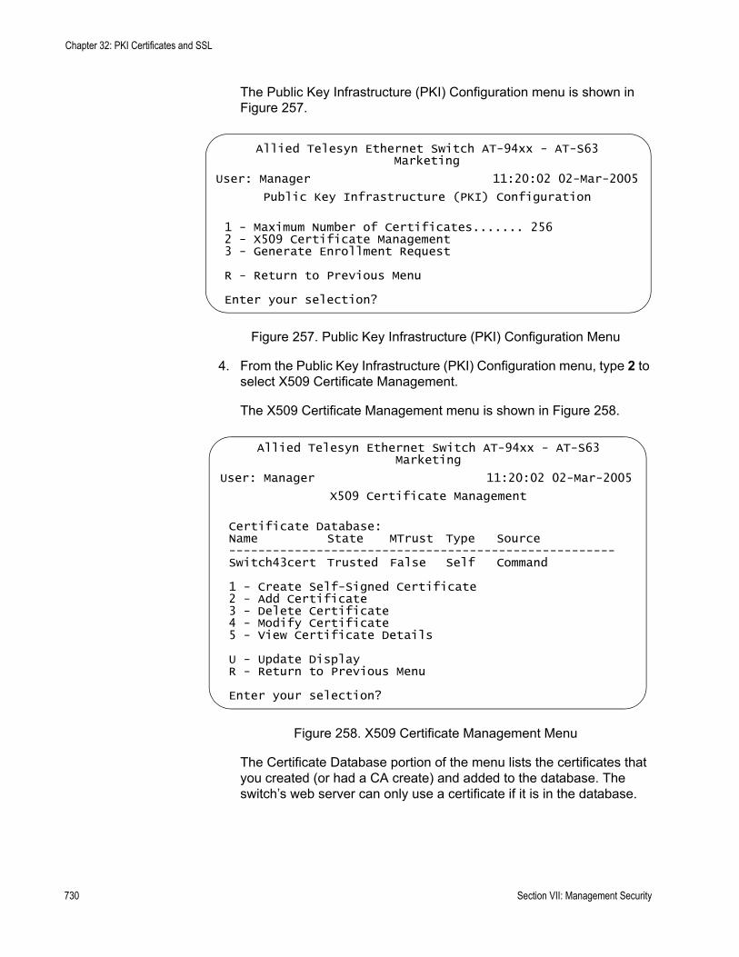
Chapter 32: PKI Certificates and SSL
The Public Key Infrastructure (PKI) Configuration menu is shown in Figure 257.
Figure 257. Public Key Infrastructure (PKI) Configuration Menu
4. From the Public Key Infrastructure (PKI) Configuration menu, type 2 to select X509 Certificate Management.
The X509 Certificate Management menu is shown in Figure 258.
Figure 258. X509 Certificate Management Menu
The Certificate Database portion of the menu lists the certificates that you created (or had a CA create) and added to the database. The switch’s web server can only use a certificate if it is in the database.
Allied Telesyn Ethernet Switch AT-94xx - AT-S63Marketing
User: Manager 11:20:02 02-Mar-2005
Public Key Infrastructure (PKI) Configuration
1 - Maximum Number of Certificates....... 2562 - X509 Certificate Management3 - Generate Enrollment Request
R - Return to Previous Menu
Enter your selection?
Allied Telesyn Ethernet Switch AT-94xx - AT-S63Marketing
User: Manager 11:20:02 02-Mar-2005
X509 Certificate Management
Certificate Database:Name State MTrust Type Source-----------------------------------------------------Switch43cert Trusted False Self Command
1 - Create Self-Signed Certificate2 - Add Certificate3 - Delete Certificate4 - Modify Certificate5 - View Certificate Details
U - Update DisplayR - Return to Previous Menu
Enter your selection?
730 Section VII: Management Security
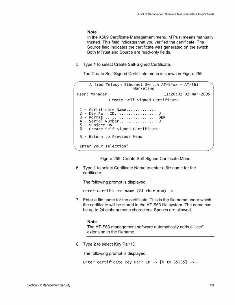
AT-S63 Management Software Menus Interface User’s Guide
NoteIn the X509 Certificate Management menu, MTrust means manually trusted. This field indicates that you verified the certificate. The Source field indicates the certificate was generated on the switch. Both MTrust and Source are read-only fields.
5. Type 1 to select Create Self-Signed Certificate.
The Create Self-Signed Certificate menu is shown in Figure 259.
Figure 259. Create Self-Signed Certificate Menu
6. Type 1 to select Certificate Name to enter a file name for the certificate.
The following prompt is displayed:
Enter certificate name (24 char max) ->
7. Enter a file name for the certificate. This is the file name under which the certificate will be stored in the AT-S63 file system. The name can be up to 24 alphanumeric characters. Spaces are allowed.
NoteThe AT-S63 management software automatically adds a “.cer” extension to the filename.
8. Type 2 to select Key Pair ID.
The following prompt is displayed:
Enter certificate Key Pair ID -> [0 to 65535] ->
Allied Telesyn Ethernet Switch AT-94xx - AT-S63Marketing
User: Manager 11:20:02 02-Mar-2005
Create Self-Signed Certificate
1 - Certificate Name.............2 - Key Pair ID.................. 03 - Format....................... DER4 - Serial Number................ 05 - Subject DN...................6 - Create Self-Signed Certificate
R - Return to Previous Menu
Enter your selection?
Section VII: Management Security 731
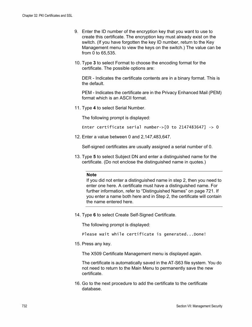
Chapter 32: PKI Certificates and SSL
9. Enter the ID number of the encryption key that you want to use to create this certificate. The encryption key must already exist on the switch. (If you have forgotten the key ID number, return to the Key Management menu to view the keys on the switch.) The value can be from 0 to 65,535.
10. Type 3 to select Format to choose the encoding format for the certificate. The possible options are:
DER - Indicates the certificate contents are in a binary format. This is the default.
PEM - Indicates the certificate are in the Privacy Enhanced Mail (PEM) format which is an ASCII format.
11. Type 4 to select Serial Number.
The following prompt is displayed:
Enter certificate serial number->[0 to 2147483647] -> 0
12. Enter a value between 0 and 2,147,483,647.
Self-signed certificates are usually assigned a serial number of 0.
13. Type 5 to select Subject DN and enter a distinguished name for the certificate. (Do not enclose the distinguished name in quotes.)
NoteIf you did not enter a distinguished name in step 2, then you need to enter one here. A certificate must have a distinguished name. For further information, refer to “Distinguished Names” on page 721. If you enter a name both here and in Step 2, the certificate will contain the name entered here.
14. Type 6 to select Create Self-Signed Certificate.
The following prompt is displayed:
Please wait while certificate is generated...Done!
15. Press any key.
The X509 Certificate Management menu is displayed again.
The certificate is automatically saved in the AT-S63 file system. You do not need to return to the Main Menu to permanently save the new certificate.
16. Go to the next procedure to add the certificate to the certificate database.
732 Section VII: Management Security

AT-S63 Management Software Menus Interface User’s Guide
Adding a Certificate to the Database
After you have created a certificate or received a certificate from a public or private CA, you need to add it into the certificate database to make it available for use by the switch’s web server. After you add a certificate to the certificate database, it appears in the X509 Certificate Management menu.
To add a certificate to the certificate database, perform the following procedure:
1. From the Main Menu, type 7 to select Security and Services.
The Security and Services menu is shown in Figure 82 on page 259.
2. From the Security and Services menu, type 7 to select Keys/Certificates Configuration.
The Keys/Certificates Configuration menu is shown in Figure 251 on page 705.
3. From the Keys/Certificate menu, type 3 to select Public Key Infrastructure (PKI) Configuration.
The Public Key Infrastructure (PKI) Configuration menu is shown in Figure 257 on page 730.
4. From the Public Key Infrastructure (PKI) Configuration menu, type 2 to select X509 Certificate Management.
The X509 Certificate Management menu is shown in Figure 258 on page 730.
5. From the X509 Certificate Management menu, type 2 to select Add Certificate.
Section VII: Management Security 733
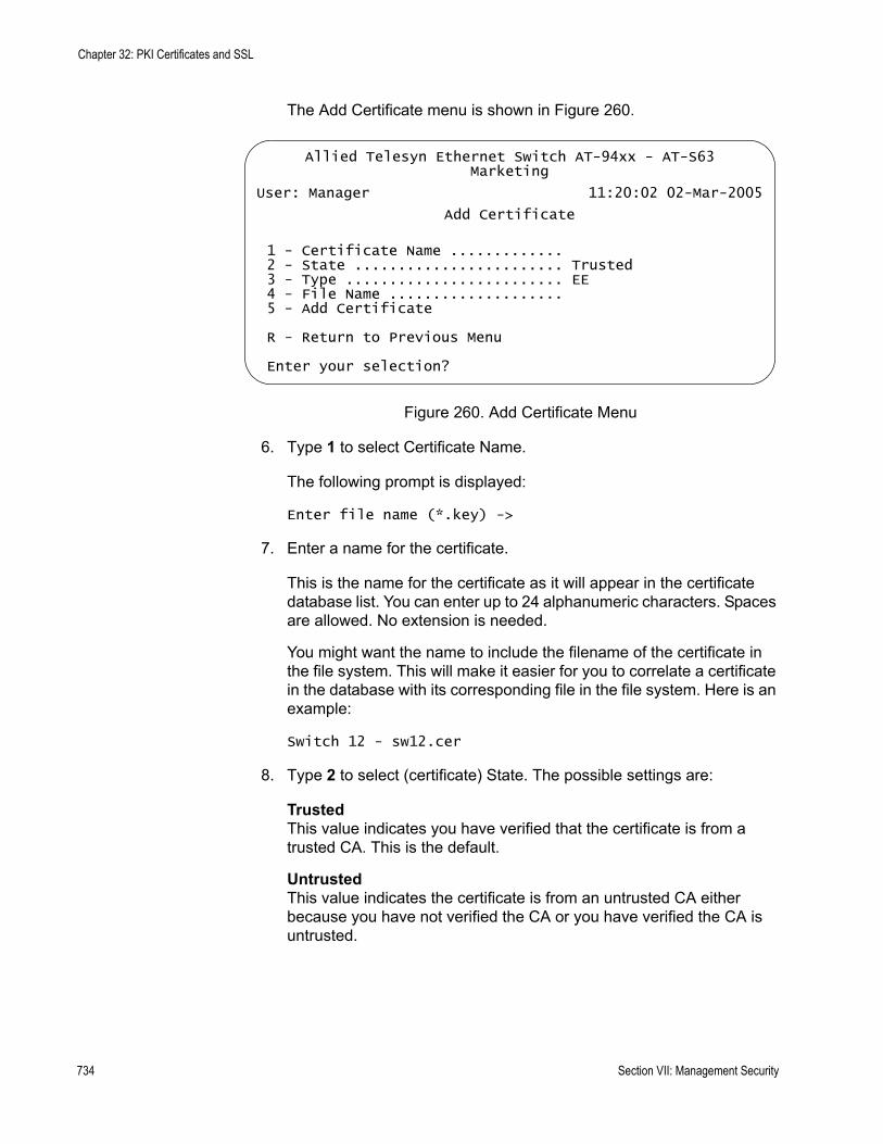
Chapter 32: PKI Certificates and SSL
The Add Certificate menu is shown in Figure 260.
Figure 260. Add Certificate Menu
6. Type 1 to select Certificate Name.
The following prompt is displayed:
Enter file name (*.key) ->
7. Enter a name for the certificate.
This is the name for the certificate as it will appear in the certificate database list. You can enter up to 24 alphanumeric characters. Spaces are allowed. No extension is needed.
You might want the name to include the filename of the certificate in the file system. This will make it easier for you to correlate a certificate in the database with its corresponding file in the file system. Here is an example:
Switch 12 - sw12.cer
8. Type 2 to select (certificate) State. The possible settings are:
TrustedThis value indicates you have verified that the certificate is from a trusted CA. This is the default.
UntrustedThis value indicates the certificate is from an untrusted CA either because you have not verified the CA or you have verified the CA is untrusted.
Allied Telesyn Ethernet Switch AT-94xx - AT-S63Marketing
User: Manager 11:20:02 02-Mar-2005
Add Certificate
1 - Certificate Name .............2 - State ........................ Trusted3 - Type ......................... EE4 - File Name .................... 5 - Add Certificate
R - Return to Previous Menu
Enter your selection?
734 Section VII: Management Security
AT-S63 Management Software Menus Interface User’s Guide
NoteThis parameter has no affect on the operation of a certificate. The parameter is included only for informational purposes when the certificate is displayed in the certificate database.
9. Type 3 to select Type (of certificate). The possible settings are:
EEThe certificate was issued by a CA, such as VeriSign. This is the default.
CAThe certificate belongs to a CA.
SelfThis certificate is a self-signed certificate. The switch treats this type of certificate as its own.
NoteThis parameter has no affect on the operation of a certificate. The parameter is included only for informational purposes when the certificate is displayed in the certificate database.
10. Type 4 to select File Name.
The following prompt is displayed:
Enter file name (*.key) ->
11. Specify the filename of the certificate.
This is the filename of the certificate in the AT-S63 file system. The filename has a “.cer” extension. For example, if you created a self-signed certificate and gave it the name “webserver127”, the filename of the certificate would be “webserver127.cer”. If you have forgotten the filename of the certificate, refer to “Displaying System Files” on page 195.
12. Type 5 to select Add Certificate to add the certificate to the certificate database.
The AT-S63 management software adds the certificate to the database, a process that requires only a few seconds.
13. After making changes, type R until you return to the Main Menu. Then type S to select Save Configuration Changes.
Section VII: Management Security 735
Chapter 32: PKI Certificates and SSL
Modifying a Certificate
The procedure in this section modifies a certificate. (The certificate to be modified must be in the certificate database.) Here are the certificate items you can modify:
State - trusted or untrustedType - EE, CA, or Self
NoteThese parameters have no affect on the operation of a certificate. They are included only for informational purposes when the certificate is displayed in the certificate database.
This procedure starts from the X509 Certificate Management menu. If you are unsure how to access the menu, perform steps 1 to 4 in the procedure “Adding a Certificate to the Database” on page 733.
To modify a certificate, perform the following procedure:
1. From the Main Menu, type 7 to select Security and Services.
The Security and Services menu is shown in Figure 82 on page 259.
2. From the Security and Services menu, type 7 to select Keys/Certificates Configuration.
The Keys/Certificates Configuration menu is shown in Figure 251 on page 705.
3. From the Keys/Certificate menu, type 3 to select Public Key Infrastructure (PKI) Configuration.
The Public Key Infrastructure (PKI) Configuration menu is shown in Figure 257 on page 730.
4. From the Public Key Infrastructure (PKI) Configuration menu, type 2 to select X509 Certificate Management.
The X509 Certificate Management menu is shown in Figure 258 on page 730.
5. From the X509 Certificate Management menu, type 4 to select Modify Certificate.
The following prompt is displayed:
Enter a certificate name ->
736 Section VII: Management Security
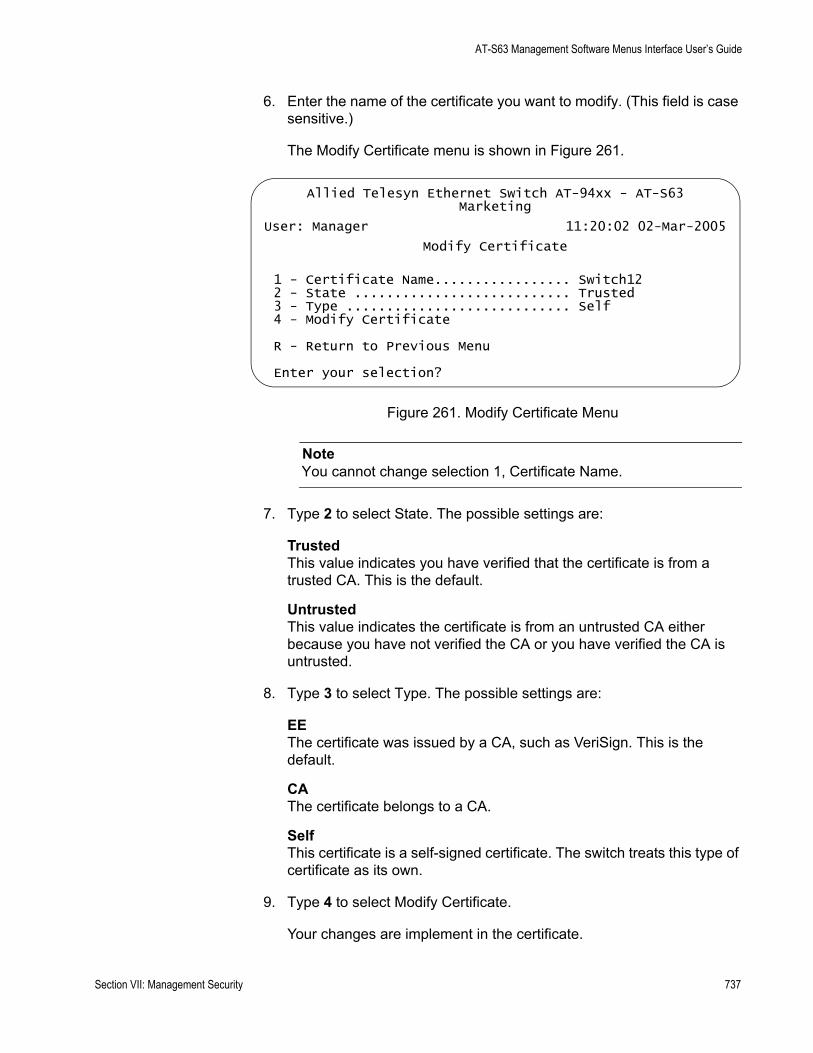
AT-S63 Management Software Menus Interface User’s Guide
6. Enter the name of the certificate you want to modify. (This field is case sensitive.)
The Modify Certificate menu is shown in Figure 261.
Figure 261. Modify Certificate Menu
NoteYou cannot change selection 1, Certificate Name.
7. Type 2 to select State. The possible settings are:
TrustedThis value indicates you have verified that the certificate is from a trusted CA. This is the default.
UntrustedThis value indicates the certificate is from an untrusted CA either because you have not verified the CA or you have verified the CA is untrusted.
8. Type 3 to select Type. The possible settings are:
EEThe certificate was issued by a CA, such as VeriSign. This is the default.
CAThe certificate belongs to a CA.
SelfThis certificate is a self-signed certificate. The switch treats this type of certificate as its own.
9. Type 4 to select Modify Certificate.
Your changes are implement in the certificate.
Allied Telesyn Ethernet Switch AT-94xx - AT-S63Marketing
User: Manager 11:20:02 02-Mar-2005
Modify Certificate
1 - Certificate Name................. Switch122 - State ........................... Trusted3 - Type ............................ Self4 - Modify Certificate
R - Return to Previous Menu
Enter your selection?
Section VII: Management Security 737

Chapter 32: PKI Certificates and SSL
The following message is displayed:
Please wait while certificate is updated...Done.
10. After making changes, type R until you return to the Main Menu. Then type S to select Save Configuration Changes.
738 Section VII: Management Security

AT-S63 Management Software Menus Interface User’s Guide
Deleting a Certificate
The procedure in this section deletes a certificate from the certificate database. Please note the following before performing this procedure:
Deleting a certificate from the database does not delete it from the switch. It continues to reside in the AT-S63 file system. To completely remove a certificate from the switch, you must also delete it from the file system. For instructions, refer to “Copying a System File” on page 190.You cannot delete a certificate from the database if you specified its corresponding encryption key as the active key in the web server configuration. The switch will consider the certificate as in use and will not allow you to delete it. You must first configure the web server with another encryption key pair for a different certificate. For instructions, refer to “Configuring the Web Server” on page 687.
This procedure starts from the X509 Certificate Management menu. If you are unsure how to access the menu, perform steps 1 to 4 in the procedure “Adding a Certificate to the Database” on page 733.
To delete a certificate from the certificate database, perform the following procedure:
1. From the Main Menu, type 7 to select Security and Services.
The Security and Services menu is shown in Figure 82 on page 259.
2. From the Security and Services menu, type 7 to select Keys/Certificates Configuration.
The Keys/Certificates Configuration menu is shown in Figure 251 on page 705.
3. From the Keys/Certificate menu, type 3 to select Public Key Infrastructure (PKI) Configuration.
The Public Key Infrastructure (PKI) Configuration menu is shown in Figure 257 on page 730.
4. From the Public Key Infrastructure (PKI) Configuration menu, type 2 to select X509 Certificate Management.
The X509 Certificate Management menu is shown in Figure 258 on page 730.
5. From the X509 Certificate Management menu, type 3 to select Delete Certificate.
The following prompt is displayed:
Section VII: Management Security 739

Chapter 32: PKI Certificates and SSL
Enter certificate name (ALL - delete all) ->
6. Enter the name of the certificate you want to delete. (This field is case sensitive.) To delete all the certificates, enter ALL.
7. After making changes, type R until you return to the Main Menu. Then type S to select Save Configuration Changes.
740 Section VII: Management Security
AT-S63 Management Software Menus Interface User’s Guide
Viewing a Certificate
This procedure displays information about a certificate, such as its distinguished name and serial number.
This procedure starts from the X509 Certificate Management menu. If you are unsure how to access the menu, perform steps 1 to 4 in the procedure “Adding a Certificate to the Database” on page 733.
To view the details of a certificate, perform the following procedure:
1. From the Main Menu, type 7 to select Security and Services.
The Security and Services menu is shown in Figure 82 on page 259.
2. From the Security and Services menu, type 7 to select Keys/Certificates Configuration.
The Keys/Certificates Configuration menu is shown in Figure 251 on page 705.
3. From the Keys/Certificate menu, type 3 to select Public Key Infrastructure (PKI) Configuration.
The Public Key Infrastructure (PKI) Configuration menu is shown in Figure 257 on page 730.
4. From the Public Key Infrastructure (PKI) Configuration menu, type 2 to select X509 Certificate Management.
The X509 Certificate Management menu is shown in Figure 258 on page 730.
5. From the X509 Certificate Management menu, type 5 to select View Certificate Details.
The following prompt is displayed:
Enter certificate name ->
6. Enter a name of the certificate you want to view. (This field is case sensitive.)
Section VII: Management Security 741
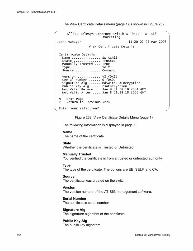
Chapter 32: PKI Certificates and SSL
The View Certificate Details menu (page 1) is shown in Figure 262.
Figure 262. View Certificate Details Menu (page 1)
The following information is displayed in page 1:
NameThe name of the certificate.
StateWhether the certificate is Trusted or Untrusted.
Manually TrustedYou verified the certificate is from a trusted or untrusted authority.
TypeThe type of the certificate. The options are EE, SELF, and CA.
SourceThe certificate was created on the switch.
VersionThe version number of the AT-S63 management software.
Serial NumberThe certificate’s serial number.
Signature AlgThe signature algorithm of the certificate.
Public Key AlgThe public key algorithm.
Allied Telesyn Ethernet Switch AT-94xx - AT-S63Marketing
User: Manager 11:20:02 02-Mar-2005
View Certificate Details
Certificate Details:Name ............... Switch12State .............. TrustedManually Trusted ... TrueType ............... SelfSource ............. Command
Version ............ V3 (0X2)Serial Number ...... 0 (0X0)Signature Alg ...... md5WithRSAEncryptionPublic Key Alg ..... rsaEncryptionNot Valid Before ... Jan 9 01:28:18 2004 GMTNot Valid After .... Jan 8 01:28:18 2006 GMT
N - Next PageR - Return to Previous Menu
Enter your selection?
742 Section VII: Management Security

AT-S63 Management Software Menus Interface User’s Guide
Not Valid BeforeThe date the certificate became active.
Not Valid AfterThe date the certificate expires. Self-signed certificates are valid for two years.
7. Type N to see the second page of certificate details.
The View Certificate Details menu (page 2) is shown in Figure 263.
Figure 263. View Certificate Details Menu (page 2)
The following information is displayed in page 2:
SubjectThe Subject distinguished name.
IssuerThe certificate issuer’s distinguished name.
MD5 Fingerprint The MD5 algorithm. This value provides a unique sequence for each certificate consisting of 16 bytes.
SHA1 Fingerprint The Secure Hash Algorithm. This value provides a unique sequence for each certificate consisting of 20 bytes.
Allied Telesyn Ethernet Switch AT-94xx - AT-S63Marketing
User: Manager 11:20:02 02-Mar-2005
View Certificate Details
Subject ......... CN=149.44.44.44Issuer .......... CN=149.44.44.44MD5 Fingerprint...4E:76:06:FA:F6:C1:DA:FF:4D:E9:76:02:1D:8F:DA:CBSHA1 Fingerprint..F8:43:CB:E2:0A:BF:4A:02:CA:C6:B0:47:DF:74:1E:D3:A8:A3:F0:00
N - Previous PageR - Return to Previous Menu
Enter your selection?
Section VII: Management Security 743
Chapter 32: PKI Certificates and SSL
Generating an Enrollment Request
To request a certificate from a CA, you need to generate an enrollment request. The request contains the public key for the certificate, a distinguished name, and other information. The request is stored as a file with a “.csr” extension in the AT-S63 file system, from where you can upload it onto your management station or FTP server for submission to the CA. (For a review of all the steps to creating an enrollment request and downloading a certificate from a CA onto a switch, refer to “General Steps for a Public or Private CA Certificate” on page 690. You must first create a key pair before you perform this procedure. For instructions, refer to “Creating an Encryption Key” on page 705.
To generate an enrollment request, perform the following procedure:
1. From the Main Menu, type 7 to select Security and Services.
The Security and Services menu is shown in Figure 82 on page 259.
2. From the Security and Services menu, type 7 to select Keys/Certificates Configuration.
The Keys/Certificates Configuration menu is shown in Figure 251 on page 705.
3. From the Keys/Certificates Configuration menu, type 1 to select Switch Distinguished Name (DN).
The following prompt is displayed:
Enter new DN (128 chars max) ->
4. Enter a name. An enrollment request must have a distinguished name. For information, refer to “Distinguished Names” on page 721.
5. Type 3 to select Public Key Infrastructure (PKI) Configuration.
The Public Key Infrastructure (PKI) Configuration menu is shown in Figure 257 on page 730.
6. From the Public Key Infrastructure (PKI) Configuration menu, type 3 to select Generate Enrollment Request.
744 Section VII: Management Security
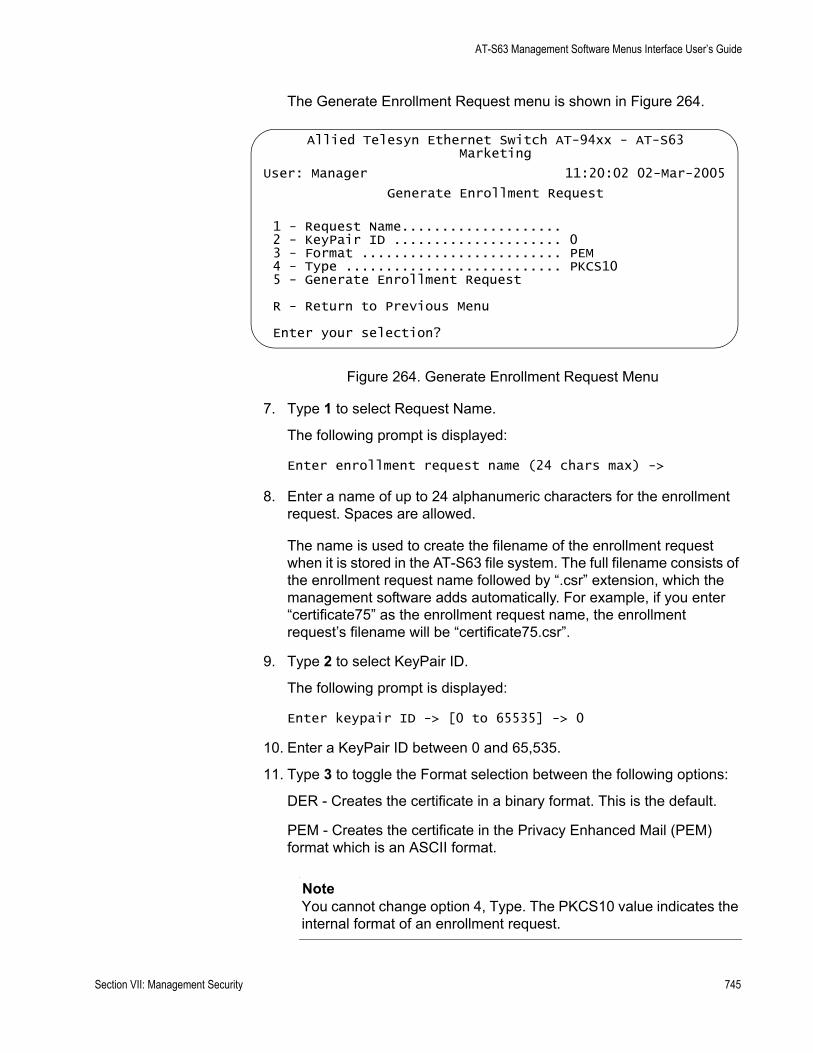
AT-S63 Management Software Menus Interface User’s Guide
The Generate Enrollment Request menu is shown in Figure 264.
Figure 264. Generate Enrollment Request Menu
7. Type 1 to select Request Name.
The following prompt is displayed:
Enter enrollment request name (24 chars max) ->
8. Enter a name of up to 24 alphanumeric characters for the enrollment request. Spaces are allowed.
The name is used to create the filename of the enrollment request when it is stored in the AT-S63 file system. The full filename consists of the enrollment request name followed by “.csr” extension, which the management software adds automatically. For example, if you enter “certificate75” as the enrollment request name, the enrollment request’s filename will be “certificate75.csr”.
9. Type 2 to select KeyPair ID.
The following prompt is displayed:
Enter keypair ID -> [0 to 65535] -> 0
10. Enter a KeyPair ID between 0 and 65,535.
11. Type 3 to toggle the Format selection between the following options:
DER - Creates the certificate in a binary format. This is the default.
PEM - Creates the certificate in the Privacy Enhanced Mail (PEM) format which is an ASCII format.
NoteYou cannot change option 4, Type. The PKCS10 value indicates the internal format of an enrollment request.
Allied Telesyn Ethernet Switch AT-94xx - AT-S63Marketing
User: Manager 11:20:02 02-Mar-2005
Generate Enrollment Request
1 - Request Name.................... 2 - KeyPair ID ..................... 03 - Format ......................... PEM4 - Type ........................... PKCS105 - Generate Enrollment Request
R - Return to Previous Menu
Enter your selection?
Section VII: Management Security 745
Chapter 32: PKI Certificates and SSL
12. Type 5 to select Generate Enrollment Request.
After the switch has finished generating the request, a message similar to the following is displayed:
Enrollment request is being generated. Please wait ...Done.Enrollment Request available in file [Switch 12.csr].Press any key to continue ...
The enrollment request is now stored in the AT-S63 file system. To see the file, refer to “Displaying System Files” on page 195.
13. Press any key to return to the Public Key Infrastructure (PKI) Configuration menu.
14. To submit the request to a CA, you must upload the enrollment request from the file system on the switch to your management station or to an FTP server on your network. For instructions, refer to “Uploading a System File” on page 222.
When you submit an enrollment request, be sure to follow the rules and guidelines of the CA. Failure to follow their guidelines may delay the issuing of the certificate.
746 Section VII: Management Security
AT-S63 Management Software Menus Interface User’s Guide
Installing CA Certificates onto a Switch
This section lists the procedures that you will need to perform if the switch’s certificate was created by a public or private CA. It should be noted that a CA generated certificate actually consists of several certificates. There is a minimum of two. All the certificates from the CA must be installed on the switch.
NoteA certificate from a CA can only be used on the switch where you created the encryption key pair and enrollment request. Do not install the certificate on any other switch.
To install CA certificates on a switch, perform the following procedure:
1. Download the certificates from your management station or FTP server to the AT-S63 file system on the switch. For instructions, refer to “Downloading a System File” on page 216.
2. Load the certificates into the certificate database. For instructions, refer to “Adding a Certificate to the Database” on page 733.
3. Activate HTTPS on the switch by configuring the web server and specifying the key pair used to create the enrollment request as the active key pair. For instructions, refer to “Configuring the Web Server” on page 687.
Section VII: Management Security 747
Chapter 32: PKI Certificates and SSL
Viewing or Configuring the Number of Certificates in the Database
The maximum number of certificates you can add to the certificate database is 12 to 256. The default value is 256. There should be little cause or need for you to adjust this value.
To view or change the number of certificates in the certificate database, perform the following procedure:
1. From the Main Menu, type 7 to select Security and Services.
The Security Configuration menu is shown in Figure 82 on page 259.
2. From the Security Configuration menu, type 7 to select Keys/Certificates Configuration.
The Keys/Certificates Configuration menu is shown in Figure 251 on page 705. Selection 1, Maximum Number of Certificates, shows the current setting.
NoteYou can specify the distinguished name for the certificate from this menu by selecting option 1, Distinguished Name, in the Keys/Certificates Configuration menu and entering the name. Or, you can wait and specify the distinguished name later in this procedure. For information about distinguished names, refer to “Distinguished Names” on page 721.
3. To change the maximum number of certificates, type 1 to select Maximum Number of Certificates.
The following prompt is displayed:
Enter certificate limit -> [12 to 256] 256
4. Enter a new number and press Return.
5. After making changes, type R until you return to the Main Menu. Then type S to select Save Configuration Changes.
748 Section VII: Management Security
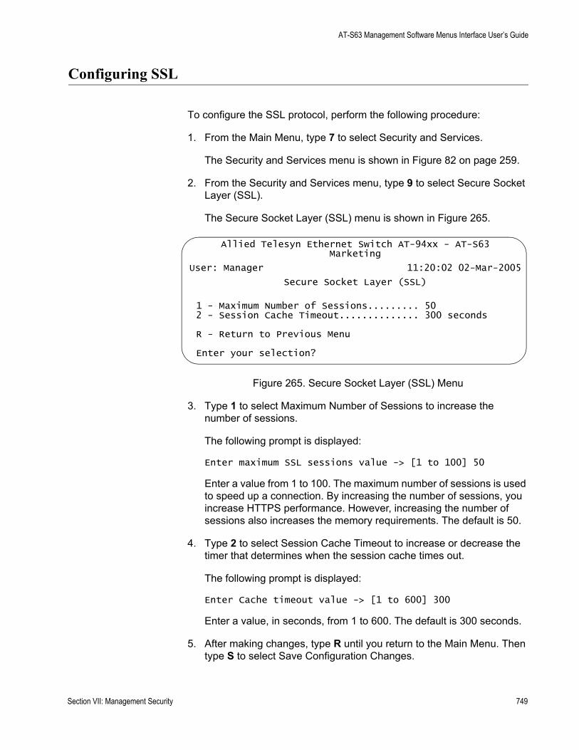
AT-S63 Management Software Menus Interface User’s Guide
Configuring SSL
To configure the SSL protocol, perform the following procedure:
1. From the Main Menu, type 7 to select Security and Services.
The Security and Services menu is shown in Figure 82 on page 259.
2. From the Security and Services menu, type 9 to select Secure Socket Layer (SSL).
The Secure Socket Layer (SSL) menu is shown in Figure 265.
Figure 265. Secure Socket Layer (SSL) Menu
3. Type 1 to select Maximum Number of Sessions to increase the number of sessions.
The following prompt is displayed:
Enter maximum SSL sessions value -> [1 to 100] 50
Enter a value from 1 to 100. The maximum number of sessions is used to speed up a connection. By increasing the number of sessions, you increase HTTPS performance. However, increasing the number of sessions also increases the memory requirements. The default is 50.
4. Type 2 to select Session Cache Timeout to increase or decrease the timer that determines when the session cache times out.
The following prompt is displayed:
Enter Cache timeout value -> [1 to 600] 300
Enter a value, in seconds, from 1 to 600. The default is 300 seconds.
5. After making changes, type R until you return to the Main Menu. Then type S to select Save Configuration Changes.
Allied Telesyn Ethernet Switch AT-94xx - AT-S63Marketing
User: Manager 11:20:02 02-Mar-2005
Secure Socket Layer (SSL)
1 - Maximum Number of Sessions......... 502 - Session Cache Timeout.............. 300 seconds
R - Return to Previous Menu
Enter your selection?
Section VII: Management Security 749

Chapter 32: PKI Certificates and SSL
750 Section VII: Management Security
Chapter 33
Secure Shell (SSH)
The chapter contains overview information about the Secure Shell (SSH) protocol as well a procedure for configuring this protocol on a switch using a local or Telnet management session. It contains the following sections:
“SSH Overview” on page 752“Configuring SSH” on page 756“Displaying SSH Information” on page 759
Section VII: Management Security 751
Chapter 33: Secure Shell (SSH)
SSH Overview
Secure management is increasingly important in modern networks, as the ability to easily and effectively manage switches and the requirement for security are two universal requirements. Switches are often remotely managed using remote sessions via the Telnet protocol. This method, however, has a serious security problem—it is only protected by plaintext usernames and passwords which are vulnerable to wiretapping and password guessing.
The Secure Shell (SSH) protocol provides encrypted and strongly authenticated remote login sessions, similar to the Telnet and rlogin protocols, between a host running a Secure Shell server and a machine with a Secure Shell client.
The AT-S63 management software features Secure Shell server software to enable network managers to securely manage the switch over an insecure network. It offers the benefit of cryptographic authentication and encryption. Secure Shell can replace Telnet for remote management sessions.
Support for SSH The AT-S63 implementation of the SSH protocol is compliant with the SSH protocol versions 1.3, 1.5, and 2.0.
In addition, the following SSH options and features are supported:
Inbound SSH connections (server mode) is supported.The following security algorithms are supported:
– 128-bit Advanced Encryption Standard (AES), 192-bit AES, and 256-bit AES
– Arcfour (RC4) security algorithm is supported.
– Triple-DES (3DES) encryption for SSH sessions is supported.
RSA public keys with lengths of 512 to 2048 bits are supported. Keys are stored in a format compatible with other Secure Shell implementations, and mechanisms are provided to copy keys to and from the switch.Compression of SSH traffic.
The following SSH options and features are not supported:
IDEA or Blowfish encryption Nonencrypted Secure Shell sessions Tunnelling of TCP/IP traffic
752 Section VII: Management Security

AT-S63 Management Software Menus Interface User’s Guide
NoteNon-encrypted Secure Shell sessions serve no purpose.
SSH Server When the SSH server is enabled, connections from SSH clients are accepted. When the SSH server is disabled, connections from SSH clients are rejected by the switch. Within the switch, the AT-S63 management software uses well-known port 22 as the SSH default port.
NoteIf your switch is in a network that is protected by a firewall, you may need to configure the firewall to permit SSH connections.
The SSH server accepts connections from configured users only. Acceptable users are those with a Manager or Operator login as well as users configured with the RADIUS and TACACS+ protocols. You can add, delete, and modify users with the RADIUS and TACACS+ feature. For information about how to configure RADIUS and TACACS+, see “Enabling or Disabling TACACS+ or RADIUS” on page 765.
SSH encryption key management is implemented by the Encryption (ENCO) protocol. You can import and export RSA public keys to and from the single-line ASCII format used by all SSH implementations. For information on how to configure the Encryption protocol, see Chapter 31, “Encryption Keys” on page 693.
SSH Clients The SSH protocol provides a secure connection between the switch and SSH clients. After you have configured the SSH server, you need to install SSH client software on your management PC. The AT-S63 management software supports both SSH1 and SSH2 clients.
You can download client software from the Internet. Two popular SSH clients are PuTTY and CYGWIN. To install SSH client software, follow the directions from the vendor.
After you have configured the SSH client software, you can use the client software to log in to the SSH server as a manager, operator, or as RADIUS/TACACS+ users. The SSH server supports multiple client connections. The maximum number of SSH clients allowed is 10 users with one manager login.
SSH andEnhanced
Stacking
The AT-S63 management software allows for encrypted SSH management sessions between a management station and a master switch of an enhanced stack, but not with slave switches, as explained in this section.
When you remotely manage a slave switch, all management communications are conducted through the master switch using the
Section VII: Management Security 753

Chapter 33: Secure Shell (SSH)
enhanced stacking feature. Management packets from your workstation are first directed to the master switch before being forwarded to the slave switch. The reverse is true as well. Management packets from a slave switch first pass through the master switch before reaching your management station.
Enhanced stacking uses a proprietary protocol different from Telnet and SSH protocols. Consequently, there is no encryption between a master switch and a slave switch. The result is that SSH encryption can only occur between your workstation and the master switch, not between your workstation and a slave switch.
This is illustrated in Figure 266. The figure shows an SSH management station that is managing a slave switch of an enhanced stack. The packets exchanged between the slave switch and the master switch are transmitted in plaintext and those exchanged between the master switch and the SSH management station are encrypted
Figure 266 SSH Remote Management of a Slave Switch
Because enhanced stacking does not allow for SSH encrypted management sessions between a management station and a slave switch, you configure SSH only on the master switch of a stack. Activating SSH on a slave switch has no affect.
SSHConfiguration
Guidelines
Below are the guidelines to observe when you configure SSH:
FAULT
RPS
MASTER
POWER
CLASS 1LASER PRODUCT
STATUSTERMINALPORT
1 3 5 7 9 11
2 4 6 8 10 12
13 15 17 19 21 23R
14 16 18 20 22 24R
AT-9424T/SP Gigabit Ethernet Switch
1 3 5 7 9 11 13 15 17 19 21 23R
2 4 6 8 10 12 14 16 18 20 22 24R
23 24
L/A
D/C
D/C
L/A
D/C
L/A 1000 LINK / ACT
HDX / COLFDX
10/100 LINK / ACTPORT ACTIVITY
L/A
1000 LINK / ACTSFPSFP
24
SFP
23
FAULT
RPS
MASTER
POWER
GBIC
23
GBIC
24
CLASS 1LASER PRODUCT
STATUSTERMINALPORT
1 3 5 7 9 11
2 4 6 8 10 12
13 15 17 19 21 23R
14 16 18 20 22 24R
AT-9424T/GB Gigabit Ethernet Switch
1 3 5 7 9 11 13 15 17 19 21 23R
2 4 6 8 10 12 14 16 18 20 22 24R
23 24
L/A
D/C
D/C
L/A
D/C
L/A 1000 LINK / ACT
HDX / COLFDX
10/100 LINK / ACTPORT ACTIVITY
L/A
1000 LINK / ACTGBIC
Plaintext Management Packets(Proprietary Enhanced Stacking Protocol)
Encrypted Management Packets(SSH Protocol)
Slave Switch
Master Switch
SSH ManagementWorkstation
754 Section VII: Management Security
AT-S63 Management Software Menus Interface User’s Guide
SSH requires two encryption key pairs. One key pair will function as the host key and the other the server key. For instructions on creating keys, refer to “Creating an Encryption Key” on page 705.The two encryption key pairs must be of different lengths of at least one increment (256 bits) apart. The recommended bit size for a server key is 768 bits. The recommended size for the host key is 1024 bits.You activate and configure SSH on the master switch of an enhanced stack, not on slave switches.The AT-S63 software uses well-known port 22 as the SSH default port.
General Steps forConfiguring SSH
Configuring the SSH server involves several procedures. This section lists the procedures you need to complete to configure the SSH feature.
1. Create two encryption key pairs on the master switch of the enhanced switch. One pair will function as the host key and the other the server key.
2. Configure and activate the Secure Shell server on the switch by specifying the two encryption keys in the server software.
For instructions, see “Configuring SSH” on page 756.
3. Install SSH client software on your management station.
Follow the directions provided with the client software. You can download SSH client software from the Internet. Two popular SSH clients are PuTTY and CYGWIN.
4. Disable the Telnet server.
Although the switch allows the SSH and Telnet servers to be enabled simultaneously, allowing Telnet to be enabled negates the security of the SSH feature. To disable the Telnet server, see “Enabling or Disabling the Telnet Server” on page 64.
5. Log in to the switch from your SSH management station.
Section VII: Management Security 755

Chapter 33: Secure Shell (SSH)
Configuring SSH
This section describes how to configure the switch as an SSH server. For a description of all the steps required to configure an SSH server, see “General Steps for Configuring SSH” on page 755.
Before you begin this procedure, you need to configure a host and server keys for SSH. See Chapter 31, “Encryption Keys” on page 693. The minimum bit size of the server key is 512 bits. The recommended bit size for a server key is 768 bits. The recommended size for the host key is 1024 bits. In addition, the bit size of the host and server keys must differ by 128 bits.
While you are configuring the SSH feature, you must disable the SSH server. When you have completed your configuration changes, enable the SSH server to permit SSH client connections.
NoteAllied Telesyn recommends disabling the Telnet server before you enable SSH. Otherwise, the security functions provided by SSH are lost. See “Enabling or Disabling the Telnet Server” on page 64.
To configure the SSH protocol, perform the following procedure:
1. From the Main Menu, type 7 to select Security and Services.
The Security and Services menu is shown in Figure 82 on page 259.
2. From the Security and Services menu, type 8 to select Secure Shell (SSH).
The Secure Shell (SSH) menu is shown in Figure 267.
Figure 267. Secure Shell (SSH) Menu
Allied Telesyn Ethernet Switch AT-94xx - AT-S63Marketing
User: Manager 11:20:02 02-Mar-2005
Secure Shell (SSH)
1 - SSH Server Status ....... Disabled2 - Host Key ID.............. <Not Defined>3 - Server Key ID ........... <Not Defined>4 - Server Key Expiry Time .. 0 hours5 - Login Timeout ........... 180 seconds6 - Show Server InformationR - Return to Previous Menu
Enter your selection?
756 Section VII: Management Security

AT-S63 Management Software Menus Interface User’s Guide
3. Type 2 to select Host Key ID.
The following prompt is displayed:
Enter Host Key ID [0 to 65535] -> 0
Enter a host key ID. The default is Not Defined. Enter a value that you configured in the encryption menus. See Chapter 31, “Encryption Keys” on page 693.
4. Type 3 to select Server Key ID.
The following prompt is displayed:
Enter Server vKey ID [0 to 65535 -> 0
Enter a server key ID. The default is Not Defined. Enter a value that you configured in the encryption menus. See Chapter 31, “Encryption Keys” on page 693.
5. Type 4 to select Server Key Expiry Time to set the time, in hours, for the server key to expire.
The following prompt is displayed:
Enter Server Key Expiry Time [0 to 5] -> 0
This timer determines how often the server key is regenerated. A server key is regenerated for security purposes. A server key is only valid for the time period configured in the Server Key Expiry (Expiration) Time timer. Allied Telesyn recommends you set this field to 1. With this setting, a new key is generated every hour.
The default is 0 hours which means the server key never expires. The range is 0 to 5 hours.
6. Type 5 to select Login Timeout.
The following prompt is displayed:
Enter Login Timeout [60 to 600] -> 180
This is the time it takes to release the SSH server from an incomplete SSH client connection. Enter a time in seconds. The default is 180 seconds (3 minutes). The range is 60 to 600 seconds.
7. Type 1 to select SSH Server Status to enable or disable the SSH server.
The following prompt is displayed:
SSH Server Status [E-Enabled, D-Disabled] ->
Section VII: Management Security 757
Chapter 33: Secure Shell (SSH)
Type E to enable the SSH server. Select this value after you have finished configuring SSH and want to log on to the server. Or, type D to disable SSH while you are configuring the protocol. SSH must be disabled while you are configuring the protocol. This is the default.
NoteWhen there are active SSH connections, you cannot disable the SSH server. If you attempt to disable the SSH server when it is in this state, you receive a warning message.
NoteAllied Telesyn recommends disabling the Telnet server before you enable SSH. Otherwise, the security provided by SSH is lost.
8. After making changes, type R to until you return to the Main Menu. Then type S to select Save Configuration Changes.
758 Section VII: Management Security
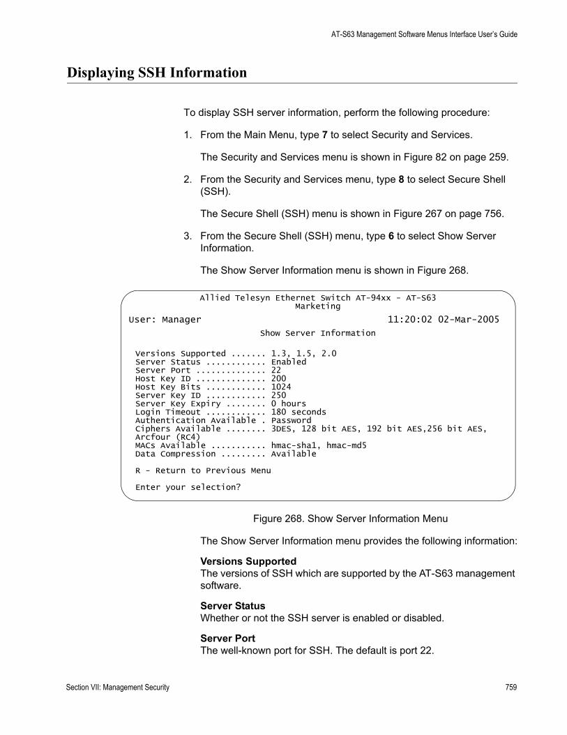
AT-S63 Management Software Menus Interface User’s Guide
Displaying SSH Information
To display SSH server information, perform the following procedure:
1. From the Main Menu, type 7 to select Security and Services.
The Security and Services menu is shown in Figure 82 on page 259.
2. From the Security and Services menu, type 8 to select Secure Shell (SSH).
The Secure Shell (SSH) menu is shown in Figure 267 on page 756.
3. From the Secure Shell (SSH) menu, type 6 to select Show Server Information.
The Show Server Information menu is shown in Figure 268.
Figure 268. Show Server Information Menu
The Show Server Information menu provides the following information:
Versions SupportedThe versions of SSH which are supported by the AT-S63 management software.
Server StatusWhether or not the SSH server is enabled or disabled.
Server PortThe well-known port for SSH. The default is port 22.
Allied Telesyn Ethernet Switch AT-94xx - AT-S63Marketing
User: Manager 11:20:02 02-Mar-2005
Show Server Information
Versions Supported ....... 1.3, 1.5, 2.0Server Status ............ EnabledServer Port .............. 22Host Key ID .............. 200Host Key Bits ............ 1024Server Key ID ............ 250Server Key Expiry ........ 0 hoursLogin Timeout ............ 180 secondsAuthentication Available . PasswordCiphers Available ........ 3DES, 128 bit AES, 192 bit AES,256 bit AES,Arcfour (RC4)MACs Available ........... hmac-sha1, hmac-md5Data Compression ......... Available
R - Return to Previous Menu
Enter your selection?
Section VII: Management Security 759

Chapter 33: Secure Shell (SSH)
Host Key IDThe host key ID defined for SSH.
Host Key BitsNumber of bits in the host key.
Server Key IDServer key ID defined for SSH.
Server Key ExpiryLength of time, in hours, until the server key is regenerated. The default is 0 hours which means the server key is not regenerated.
Login TimeoutTime, in seconds, until a SSH server is released from an incomplete connection with a SSH client.
Authentication AvailableAuthentication method available. Currently, password authentication is the only supported method.
Ciphers AvailableSSH ciphers that are available on the switch.
MACs AvailableMessage Authorization Code (MAC) that is used to validate incoming SSH messages to the server. Two algorithms are supported.
Data CompressionWhether or not data compression is available on the switch. Data compression is useful for networks that have a slow throughput speed.
760 Section VII: Management Security
Chapter 34
TACACS+ and RADIUS Protocols
This chapter describes how you can use two authentication protocols, TACACS+ and RADIUS, to control who can log onto a switch to manage it. Sections in the chapter include:
“TACACS+ and RADIUS Overview” on page 762“Enabling or Disabling TACACS+ or RADIUS” on page 765“Configuring TACACS+” on page 767“Displaying the TACACS+ Settings” on page 769“Configuring RADIUS” on page 771“Displaying RADIUS Status and Settings” on page 773
Section VII: Management Security 761
Chapter 34: TACACS+ and RADIUS Protocols
TACACS+ and RADIUS Overview
The AT-S63 management software has two standard manager login accounts: manager and operator. The manager account lets you change a switch’s parameter settings while the operator account lets you view the settings, but not change them. Each account has its own password. The manager account has a default password of “friend” and the operator account has a default password “operator.”
For those networks that are managed by just one or two network managers, the standard accounts may be all you need. However, for larger networks managed by several network managers, you might want to give each manager his or her own management login account rather than have them share an account.
This is where TACACS+ and RADIUS can be useful. TACACS+ is an acronym for Terminal Access Controller Access Control System. RADIUS is an acronym for Remote Authentication Dial In User Services. These are authentication protocols. You can use them to transfer the task of validating management access from an AT-9400 Series switch to an authentication protocol server.
With the protocols you can create a series of username and password combinations that define who can manage an AT-9400 Series switch.
There are three basic functions an authentication protocol provides:
AuthenticationAuthorizationAccounting
When a network manager logs in to a switch to manage the device, the switch passes the username and password entered by the manager to the authentication protocol server. The server checks to see if the username and password are valid for that switch. This is referred to as authentication.
If the combination is valid, the authentication protocol server notifies the switch and the switch completes the login process, allowing the manager to manage the switch.
If the username and password are invalid, the authentication protocol server notifies the switch and the switch cancels the login.
Authorization defines what a manager can do after logging in to a switch. You assign an authorization level to each username and password combination that you create on the server software. The access level can either Manager or Operator.
762 Section VII: Management Security
AT-S63 Management Software Menus Interface User’s Guide
The final function of an authentication protocol is accounting, which keeps track of user activity on network devices. The AT-S63 management software does not support RADIUS or TACACS+ accounting as part of manager accounts. However, it does support RADIUS accounting with the 802.1x Port-based Network Access Control feature, as explained in Chapter 28, “802.1x Port-based Network Access Control” on page 647.
NoteThe AT-S63 management software does not support the two earlier versions of the TACACS+ protocol, TACACS and XTACACS.
TACACS+ andRADIUS
ImplementationGuidelines
What do you need to use the TACACS+ and RADIUS protocols? Following are the main points.
First, you need to install TACACS+ or RADIUS server software on one or more of your network servers or management stations. Authentication protocol server software is not available from Allied Telesyn.The authentication protocol server can be on the same subnet or a different subnet as the AT-9400 Series switch. If the server and switch are on different subnets, be sure to specify a default gateway in the System Configuration menu (Figure 5 on page 47) so that the switch and server can communicate with each other.You need to configure the TACACS+ or RADIUS software on the authentication server. This involves the following:
– Specifying the username and password combinations. The maximum length for a username is 38 alphnumeric characters and spaces, and the maximum length for a password is 16 alphnumeric characters and spaces.
– Assigning each combination an authorization level. How this is achieved differs depending on the server software you are using. TACACS+ controls this through the sixteen (0 to 15) different levels of the Privilege attribute. A privilege level of “0” gives the combination Operator status. Any value from 1 to 15 gives the combination Manager status.
For RADIUS, management level is controlled by the Service Type attribute. This attribute has 11 different values; only two apply to the AT-S63 management software. A value of Administrative for this attribute gives the username and password combination Manager access. A value of NAS Prompt assigns the combination Operator status.
Section VII: Management Security 763
Chapter 34: TACACS+ and RADIUS Protocols
NoteThis manual does not explain how to configure TACACS+ or RADIUS server software. For that you need to refer to the documentation that came with the software.
You must activate the TACACS+ or RADIUS client software on the switch using the AT-S63 management software and configure the settings, which includes the IP addresses of up to three authentication server. The procedure for this step is found in this chapter.
By default, authentication protocol is disabled in the AT-S63 management software. After you activate it, you need to provide the following information:
Which authentication protocol you want to use. Only one authentication protocol can be active on a switch at a time.IP addresses of up to three authentication servers.The encryption key used by the authentication servers.
You can specify up to three RADIUS or TACACS+ servers. Specifying multiple servers adds redundancy to your network. For example, removing an authentication server from the network for maintenance does not prevent network managers from logging into switches if there are one or two other authentication servers on the network.
When a switch receives a username and password combination from a network manager, it sends the combination to the first authentication server in its list. If the server fails to respond, the switch sends the combination to the next server in the list, and so on.
If no authentication server responds or if no servers have been defined and you are managing the switch locally, the AT-S63 management software defaults to the standard manager and operator accounts.
NoteFor more information on TACACS+, refer to the RFC 1492 standard. For more information on RADIUS, refer to the RFC 2865 standard.
764 Section VII: Management Security
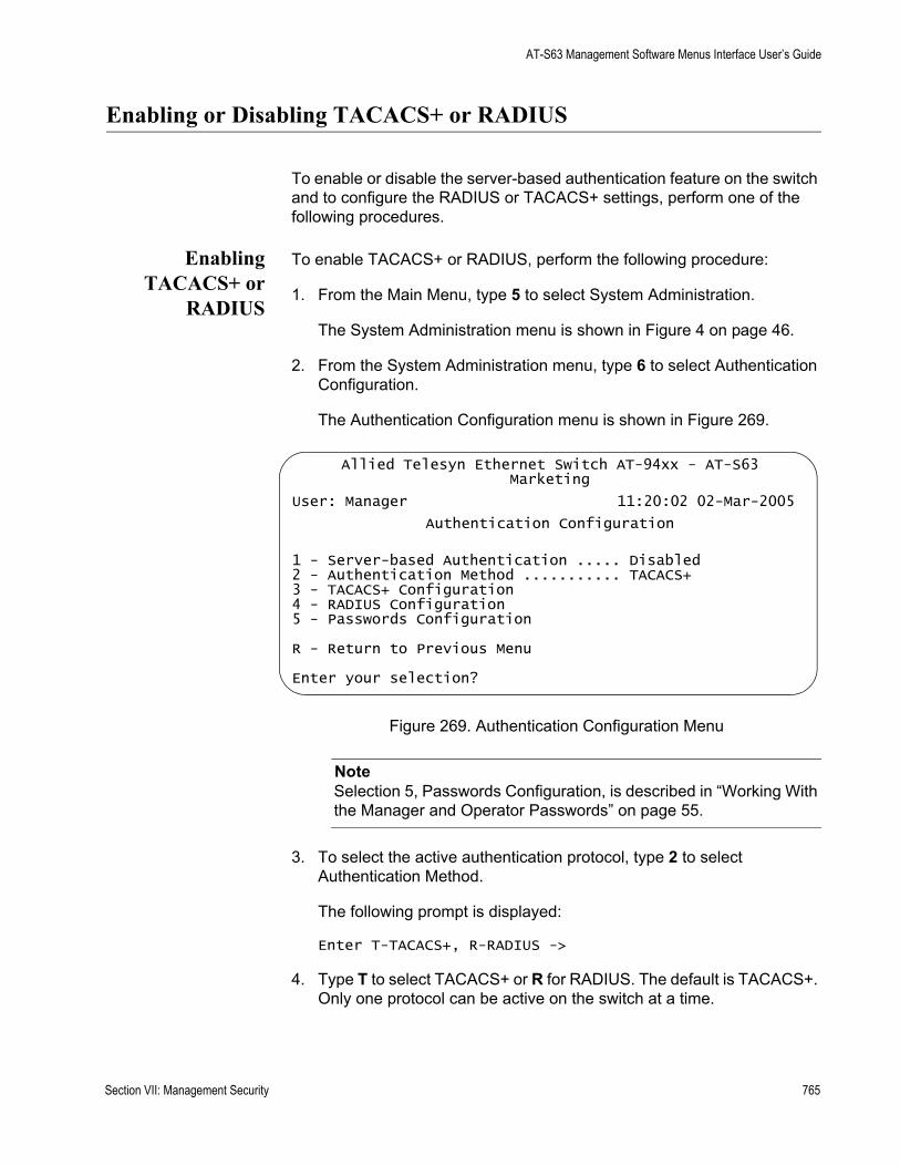
AT-S63 Management Software Menus Interface User’s Guide
Enabling or Disabling TACACS+ or RADIUS
To enable or disable the server-based authentication feature on the switch and to configure the RADIUS or TACACS+ settings, perform one of the following procedures.
EnablingTACACS+ or
RADIUS
To enable TACACS+ or RADIUS, perform the following procedure:
1. From the Main Menu, type 5 to select System Administration.
The System Administration menu is shown in Figure 4 on page 46.
2. From the System Administration menu, type 6 to select Authentication Configuration.
The Authentication Configuration menu is shown in Figure 269.
Figure 269. Authentication Configuration Menu
NoteSelection 5, Passwords Configuration, is described in “Working With the Manager and Operator Passwords” on page 55.
3. To select the active authentication protocol, type 2 to select Authentication Method.
The following prompt is displayed:
Enter T-TACACS+, R-RADIUS ->
4. Type T to select TACACS+ or R for RADIUS. The default is TACACS+. Only one protocol can be active on the switch at a time.
Allied Telesyn Ethernet Switch AT-94xx - AT-S63Marketing
User: Manager 11:20:02 02-Mar-2005
Authentication Configuration
1 - Server-based Authentication ..... Disabled2 - Authentication Method ........... TACACS+3 - TACACS+ Configuration4 - RADIUS Configuration5 - Passwords Configuration
R - Return to Previous Menu
Enter your selection?
Section VII: Management Security 765
Chapter 34: TACACS+ and RADIUS Protocols
NoteBefore enabling server-based authentication on the switch, you should first configure the TACACS+ or RADIUS settings. If you selected TACACS+, go to “Configuring TACACS+” on page 767. If you selected RADIUS, go to “Configuring RADIUS” on page 771.
DisablingTACACS+ or
RADIUS
To disable the authentication feature on the switch, perform the following procedure:
1. From the Main Menu, type 5 to select System Administration.
The System Administration menu is shown in Figure 4 on page 46.
2. From the System Administration menu, type 6 to select Authentication Configuration.
The Authentication Configuration menu is shown in Figure 269 on page 765.
3. From the Authentication Configuration menu, type 1 to select Server-based Authentication.
The following prompt is displayed:
Server Based User Authentication (E-Enabled, D-Disabled) ->
4. Type D to disable the feature. The default is disabled.
5. After making changes, type R until you return to the Main Menu. Then type S to select Save Configuration Changes.
766 Section VII: Management Security
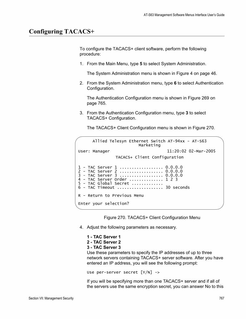
AT-S63 Management Software Menus Interface User’s Guide
Configuring TACACS+
To configure the TACACS+ client software, perform the following procedure:
1. From the Main Menu, type 5 to select System Administration.
The System Administration menu is shown in Figure 4 on page 46.
2. From the System Administration menu, type 6 to select Authentication Configuration.
The Authentication Configuration menu is shown in Figure 269 on page 765.
3. From the Authentication Configuration menu, type 3 to select TACACS+ Configuration.
The TACACS+ Client Configuration menu is shown in Figure 270.
Figure 270. TACACS+ Client Configuration Menu
4. Adjust the following parameters as necessary.
1 - TAC Server 12 - TAC Server 23 - TAC Server 3Use these parameters to specify the IP addresses of up to three network servers containing TACACS+ server software. After you have entered an IP address, you will see the following prompt:
Use per-server secret [Y/N] ->
If you will be specifying more than one TACACS+ server and if all of the servers use the same encryption secret, you can answer No to this
Allied Telesyn Ethernet Switch AT-94xx - AT-S63Marketing
User: Manager 11:20:02 02-Mar-2005
TACACS+ Client Configuration
1 - TAC Server 1 .................. 0.0.0.02 - TAC Server 2 .................. 0.0.0.03 - TAC Server 3 .................. 0.0.0.04 - TAC Server Order .............. 1 2 35 - TAC Global Secret .............6 - TAC Timeout ................... 30 seconds
R - Return to Previous Menu
Enter your selection?
Section VII: Management Security 767

Chapter 34: TACACS+ and RADIUS Protocols
prompt and enter the encryption secret using the TAC Global Secret parameter.
However, if you are specifying only one TACACS+ server or if the servers have difference encryption secrets, then respond with Yes to this prompt. You will see:
Enter per-server secret [max 40 characters] ->
Use this prompt to enter the encryption secret for the TACACS+ server whose IP address you are specifying.
4 - TAC Server OrderUse this selection to indicate the order in which you want the switch to query the TACACS+ servers for logon authentication. Of course, you can skip this option if you specified only one IP address. The default is 1, 2, and 3, in that order.
5 - TAC Global SecretIf all of the TACACS+ servers have the same encryption secret, rather then entering the same secret when you enter the IP addresses, you can use this option to enter the secret only once.
3 - TAC TimeoutThis parameter specifies the maximum amount of time the switch waits for a response from a TACACS+ server before assuming the server is not responding. If the timeout expires and the server has not responded, the switch queries the next TACACS+ server in the list. If there are no more servers, the switch defaults to the standard Manager and Operator accounts. The default is 30 seconds. The range is 1 to 300 seconds.
5. After you have finished configuring the parameters in the TACACS+ Client Configuration menu, type R to return to the Authentication Configuration menu, shown in Figure 269 on page 765.
6. From the Authentication Configuration menu, type 1 to select Server-based Authentication.
The following prompt is displayed:
Server Based User Authentication (E-Enabled, D-Disabled) ->
7. Type E to enable server-based authentication on the switch.
8. The TACACS+ client software is now active on the switch.
9. After making changes, type R until you return to the Main Menu. Then type S to select Save Configuration Changes.
768 Section VII: Management Security

AT-S63 Management Software Menus Interface User’s Guide
Displaying the TACACS+ Settings
To display the TACACS+ settings, perform the following procedure:
1. From the Main Menu, type 5 to select System Administration.
The System Administration menu is shown in Figure 4 on page 46.
2. From the System Administration menu, type 6 to select Authentication Configuration.
The Authentication Configuration menu is shown in Figure 269 on page 765.
3. Type 3 to select TACACS+ Configuration.
The TACACS+ Client Configuration menu is shown in Figure 271.
Figure 271. TACACS+ Client Configuration Menu
The TACACS+ Client Configuration menu provides the following information:
TAC Server 1TAC Server 2TAC Server 3The IP addresses of the TACACS+ servers.
TAC Server OrderThe order in which the switch to queries the TACACS+ servers for logon authentication.
TAC Global SecretGlobal encryption secret if all the servers use the same one.
Allied Telesyn Ethernet Switch AT-94xx - AT-S63Marketing
User: Manager 11:20:02 02-Mar-2005
TACACS+ Client Configuration
1 - TAC Server 1 .................. 142.34.56.1022 - TAC Server 2 .................. 0.0.0.03 - TAC Server 3 .................. 0.0.0.04 - TAC Server Order .............. 1 2 35 - TAC Global Secret ............. tech6 - TAC Timeout ................... 30 seconds
R - Return to Previous Menu
Enter your selection?
Section VII: Management Security 769

Chapter 34: TACACS+ and RADIUS Protocols
TAC TimeoutThe maximum amount of time the switch waits for a response from a TACACS+ server before assuming the server is not responding.
770 Section VII: Management Security
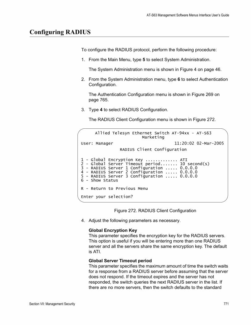
AT-S63 Management Software Menus Interface User’s Guide
Configuring RADIUS
To configure the RADIUS protocol, perform the following procedure:
1. From the Main Menu, type 5 to select System Administration.
The System Administration menu is shown in Figure 4 on page 46.
2. From the System Administration menu, type 6 to select Authentication Configuration.
The Authentication Configuration menu is shown in Figure 269 on page 765.
3. Type 4 to select RADIUS Configuration.
The RADIUS Client Configuration menu is shown in Figure 272.
Figure 272. RADIUS Client Configuration
4. Adjust the following parameters as necessary.
Global Encryption KeyThis parameter specifies the encryption key for the RADIUS servers. This option is useful if you will be entering more than one RADIUS server and all the servers share the same encryption key. The default is ATI.
Global Server Timeout periodThis parameter specifies the maximum amount of time the switch waits for a response from a RADIUS server before assuming that the server does not respond. If the timeout expires and the server has not responded, the switch queries the next RADIUS server in the list. If there are no more servers, then the switch defaults to the standard
Allied Telesyn Ethernet Switch AT-94xx - AT-S63Marketing
User: Manager 11:20:02 02-Mar-2005
RADIUS Client Configuration
1 - Global Encryption Key ............. ATI2 - Global Server Timeout period....... 10 second(s)3 - RADIUS Server 1 Configuration ..... 0.0.0.04 - RADIUS Server 2 Configuration ..... 0.0.0.05 - RADIUS Server 3 Configuration ..... 0.0.0.06 - Show Status
R - Return to Previous Menu
Enter your selection?
Section VII: Management Security 771
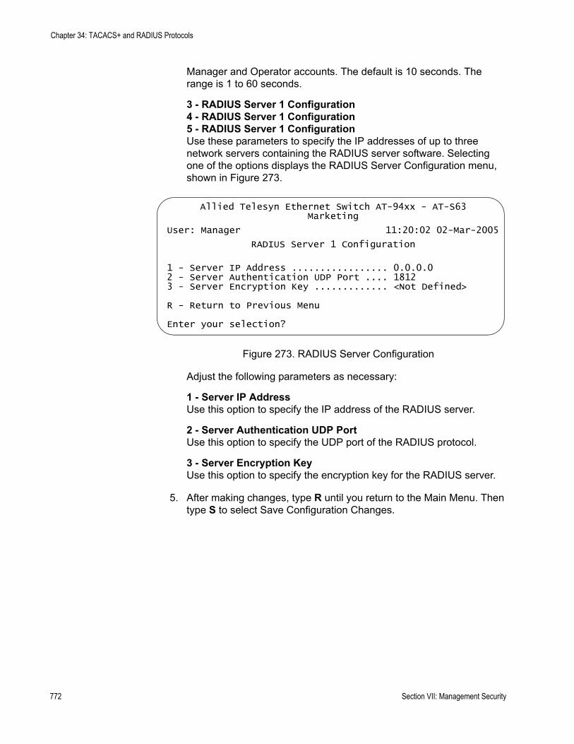
Chapter 34: TACACS+ and RADIUS Protocols
Manager and Operator accounts. The default is 10 seconds. The range is 1 to 60 seconds.
3 - RADIUS Server 1 Configuration4 - RADIUS Server 1 Configuration5 - RADIUS Server 1 ConfigurationUse these parameters to specify the IP addresses of up to three network servers containing the RADIUS server software. Selecting one of the options displays the RADIUS Server Configuration menu, shown in Figure 273.
Figure 273. RADIUS Server Configuration
Adjust the following parameters as necessary:
1 - Server IP AddressUse this option to specify the IP address of the RADIUS server.
2 - Server Authentication UDP PortUse this option to specify the UDP port of the RADIUS protocol.
3 - Server Encryption KeyUse this option to specify the encryption key for the RADIUS server.
5. After making changes, type R until you return to the Main Menu. Then type S to select Save Configuration Changes.
Allied Telesyn Ethernet Switch AT-94xx - AT-S63Marketing
User: Manager 11:20:02 02-Mar-2005
RADIUS Server 1 Configuration
1 - Server IP Address ................. 0.0.0.02 - Server Authentication UDP Port .... 18123 - Server Encryption Key ............. <Not Defined>
R - Return to Previous Menu
Enter your selection?
772 Section VII: Management Security
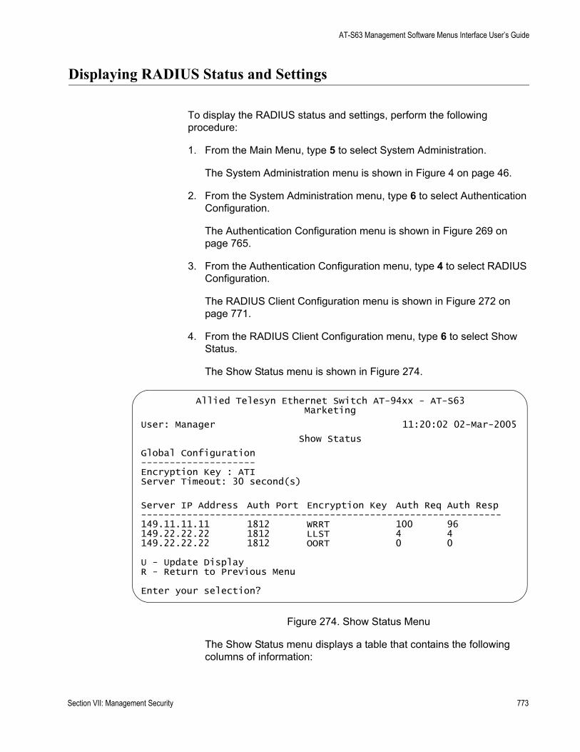
AT-S63 Management Software Menus Interface User’s Guide
Displaying RADIUS Status and Settings
To display the RADIUS status and settings, perform the following procedure:
1. From the Main Menu, type 5 to select System Administration.
The System Administration menu is shown in Figure 4 on page 46.
2. From the System Administration menu, type 6 to select Authentication Configuration.
The Authentication Configuration menu is shown in Figure 269 on page 765.
3. From the Authentication Configuration menu, type 4 to select RADIUS Configuration.
The RADIUS Client Configuration menu is shown in Figure 272 on page 771.
4. From the RADIUS Client Configuration menu, type 6 to select Show Status.
The Show Status menu is shown in Figure 274.
Figure 274. Show Status Menu
The Show Status menu displays a table that contains the following columns of information:
Allied Telesyn Ethernet Switch AT-94xx - AT-S63Marketing
User: Manager 11:20:02 02-Mar-2005
Show Status
Global Configuration--------------------Encryption Key : ATIServer Timeout: 30 second(s)
Server IP Address Auth Port Encryption Key Auth Req Auth Resp---------------------------------------------------------------149.11.11.11 1812 WRRT 100 96149.22.22.22 1812 LLST 4 4149.22.22.22 1812 OORT 0 0
U - Update DisplayR - Return to Previous Menu
Enter your selection?
Section VII: Management Security 773

Chapter 34: TACACS+ and RADIUS Protocols
Server IP AddressIP address of the RADIUS server.
Auth PortUDP port of the RADIUS protocol.
Encryption KeyEncryption key for the RADIUS server.
Auth ReqNumber of authentication requests the switch has made to the RADIUS server.
Auth RespNumber of responses that the switch has received back from the server.
774 Section VII: Management Security

Chapter 35
Management Access Control Lists
This chapter explains how to create an access control list (ACL) to restrict Telnet and web browser management access to the switch. Sections in this chapter include:
“Management ACL Security Overview” on page 776“Creating the Management ACL” on page 780“Adding an ACE” on page 783“Deleting an ACE” on page 784“Displaying the ACEs” on page 785
Section VII: Management Security 775
Chapter 35: Management Access Control Lists
Management ACL Security Overview
This chapter explains how to restrict remote management access of a switch by creating a management access control list (management ACL). This feature controls which management stations can remotely manage the device using the Telnet application protocol or a web browser.
The switch uses the management ACL to filter the management packets that it receives. The switch accepts and processes only those management packets that meet the criteria stated in the ACL. Those management packets that do not meet the criteria are discarded.
The benefit of this feature is that you can prevent unauthorized access to the switch by controlling which workstations are to have remote management access. You can even control which method, Telnet or web browser, that a remote manager can use.
For example, you can create a management ACL that allows the switch to accept management packets only from the management stations in one subnet or from just one or two specific management stations.
An access control list (ACL) is a list of one or more statements that define which management packets the switch accepts. Each statement, referred to as an access control entry (ACE), contains criteria that the switch uses in making the determination.
An ACE in a management ACL is an implicit “permit” statement. This means that a management packet that meets the criteria of an ACE is processed by the switch. Consequently, the ACEs that you enter into the management ACL should specify which management packets you want the switch to process. Packets that do not meet any of the ACEs in the management ACL are discarded.
Parts of aManagement
ACE
An ACE in a management ACL has the following four parts:
IP addressSubnet maskProtocolInterface
IP Address
You can specify the IP address of a specific management station or a subnet.
776 Section VII: Management Security
AT-S63 Management Software Menus Interface User’s Guide
Mask
You need to enter a mask that indicates the parts of the IP address the switch should filter on. A binary “1” indicates the switch should filter on the corresponding bit of the address, while a “0” indicates that it should not. If you are filtering on a specific IP address, use the mask 255.255.255.255. If you are filtering on a subnet, enter the appropriate mask. For example, to allow all management stations in the subnet 149.11.11.0 to manage the switch, you would enter the mask 255.255.255.0.
Protocol
The AT-S63 management software allows you to choose TCP, UDP, or both as the protocol for the management packets. However, because Telnet and web browser management packets for an AT-9400 Series switch are exclusively TCP, specify only that protocol.
Interface
The interface parameter allows you control whether the remote management station can manage the switch using Telnet, a web browser, or both. For example, you might create an ACE that states that a particular remote management station can only use a web browser to manage the switch.
ManagementACL Guidelines
Below are guidelines to observe when you create a management ACL:
The default setting for this feature is disabled.A switch can have only one management ACL.A management ACL can have up to 256 ACEs.An ACE must have an IP address and mask.All management ACEs are implicit “permit” statements. A management packet that meets the criteria of an ACE is accepted by the switch. Consequently, the ACEs that you enter into the management ACL should specify which management packets you want the switch to process. Management packets that do not meet any of the ACEs in the management ACL are discarded.A management packet that meets an ACE is immediately processed by the switch and is not compared against any remaining ACEs in the management ACL.The ACEs are performed in the order in which they are entered in the ACL. Because all ACEs in a management ACL are implicit permit statements, it does not matter in which order you enter them.The protocol is always TCP.The management ACL does not control local management or remote SNMP management of a switch.
Section VII: Management Security 777

Chapter 35: Management Access Control Lists
Activating this feature without specifying any ACEs prohibits you from managing the switch remotely using a Telnet application or web browser because the switch discards all Telnet and web browser management packets.You can apply management ACLs to both master and slave switches in an enhanced stack. A management ACL on a master switch filters management packets intended for the master switch as well as those intended for any slave switches that you manage through the master switch. A management ACL applied to a slave switch filters only those management packets directed to the slave switch.
Examples Following are several examples of management ACLs and ACEs:.
This ACE allows the management station with the IP address 149.11.11.11 to remotely manage the switch using either the Telnet application protocol or a web browser:
IP Address 149.11.11.11Mask 255.255.255.255Protocol TCPInterface All
If the management ACL contained only the above ACE, then only the management station specified in the ACE would be allowed to manage the switch.
This ACE allows all management stations in the subnet 149.11.11.0 to remotely manage the switch using either the Telnet application or a web browser:
IP Address 149.11.11.0Mask 255.255.255.0Protocol TCPInterface All
This ACE allows all management stations in the subnet 149.11.11.0 to remotely manage the switch using a web browser, but not the Telnet application:
IP Address 149.11.11.0Mask 255.255.255.0Protocol TCPInterface Web
A management ACL can contain multiple ACEs. The two ACEs in this ACL allow all management packets from the subnets 149.11.11.0 and 149.22.22.0 to manage the switch using the Telnet application, but not a web browser:
778 Section VII: Management Security
AT-S63 Management Software Menus Interface User’s Guide
ACE #1
IP Address 149.11.11.0Subnet Mask 255.255.255.0Protocol TCPInterface Telnet
ACE #2
IP Address 149.22.22.0Subnet Mask 255.255.255.0Protocol TCPInterface Telnet
The two ACEs in this management ACL permit remote management from the management station with the IP address 149.11.11.11 and all management stations in the subnet 149.22.22.0:
ACE #1
IP Address 149.11.11.11Mask 255.255.255.255Protocol TCPInterface All
ACE #2
IP Address 149.22.22.0Mask 255.255.255.0Protocol TCPInterface All
Section VII: Management Security 779
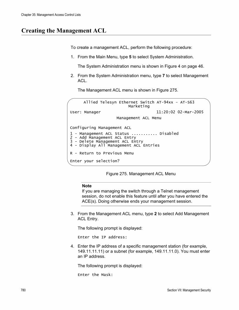
Chapter 35: Management Access Control Lists
Creating the Management ACL
To create a management ACL, perform the following procedure:
1. From the Main Menu, type 5 to select System Administration.
The System Administration menu is shown in Figure 4 on page 46.
2. From the System Administration menu, type 7 to select Management ACL.
The Management ACL menu is shown in Figure 275.
Figure 275. Management ACL Menu
NoteIf you are managing the switch through a Telnet management session, do not enable this feature until after you have entered the ACE(s). Doing otherwise ends your management session.
3. From the Management ACL menu, type 2 to select Add Management ACL Entry.
The following prompt is displayed:
Enter the IP address:
4. Enter the IP address of a specific management station (for example, 149.11.11.11) or a subnet (for example, 149.11.11.0). You must enter an IP address.
The following prompt is displayed:
Enter the Mask:
Allied Telesyn Ethernet Switch AT-94xx - AT-S63Marketing
User: Manager 11:20:02 02-Mar-2005
Management ACL Menu
Configuring Management ACL
1 - Management ACL Status ........... Disabled2 - Add Management ACL Entry3 - Delete Management ACL Entry4 - Display All Management ACL Entries
R - Return to Previous Menu
Enter your selection?
780 Section VII: Management Security

AT-S63 Management Software Menus Interface User’s Guide
5. Enter a mask that indicates the parts of the IP address the switch should filter on. A binary “1” indicates the switch should filter on the corresponding bit of the address, while a “0” indicates that it should not. If you are filtering on a specific IP address, use the mask 255.255.255.255. If you are filtering on a subnet, enter the appropriate mask. For example, to allow all management stations in the subnet 149.11.11.0 to manage the switch, you would enter the mask 255.255.255.0.
The following prompt is displayed:
Enter the Protocol [TCP/UDP/ALL]:
6. Enter either TCP or ALL.
The AT-S63 management software allows you to select UDP, but because management packets from Telnet and web browser management sessions are TCP, you should specify TCP or ALL.
The following prompt is displayed:
Enter the Interface [TELNET/WEB/ALL]:
7. Specify which interface you want the management station to be able to use when managing the switch. The options are:
Telnet - Allows Telnet management packets.
Web - Allows web browser management packets.
All - Allows both Telnet and web browser management packets.
8. If needed, repeat this procedure starting with Step 3 to add more ACEs to the management ACL.
9. After you have added all of the ACEs, type 1 to select Management ACL Status.
The following message is displayed:
You are enabling MGMT ACL. All existing Web and Telnet would be blocked. Do you wish to continue? [Yes/No]
10. Type Y for Yes or N for No to cancel the process.
NoteIf you activate this feature without specifying any ACEs, all Telnet and web browser management packets are discarded by the switch and you cannot manage the device remotely.
The management ACL is now active on the switch.
Section VII: Management Security 781

Chapter 35: Management Access Control Lists
11. After making changes, type R until you return to the Main Menu. Then type S to select Save Configuration Changes.
782 Section VII: Management Security

AT-S63 Management Software Menus Interface User’s Guide
Adding an ACE
To add an ACE, repeat the procedure in “Creating the Management ACL” on page 780. The new ACEs that you enter are added to the ACEs that are already in the management ACL.
Section VII: Management Security 783
Chapter 35: Management Access Control Lists
Deleting an ACE
To delete an ACE, perform the following procedure:
1. From the Main Menu, type 5 to select System Administration.
The System Administration menu is shown in Figure 4 on page 46.
2. From the System Administration menu, type 7 to select Management ACL menu.
The Management ACL menu is shown in Figure 275 on page 780.
3. From the Management ACL menu, type 3 to select Delete Management ACL Entry.
The following prompt is displayed:
Enter the IP Address:
4. Enter the IP address for the ACE you want to delete.
The AT-S63 management software prompts you to enter the specifics of the ACE that you want to delete. (It can help to first display the contents of the management ACL, using the procedure in ”Displaying the ACEs”, next, and jot down on paper the IP address, mask, protocol, and Interface information on the ACE you want to delete. In that way you will have the information when the software prompts you for it.)
784 Section VII: Management Security
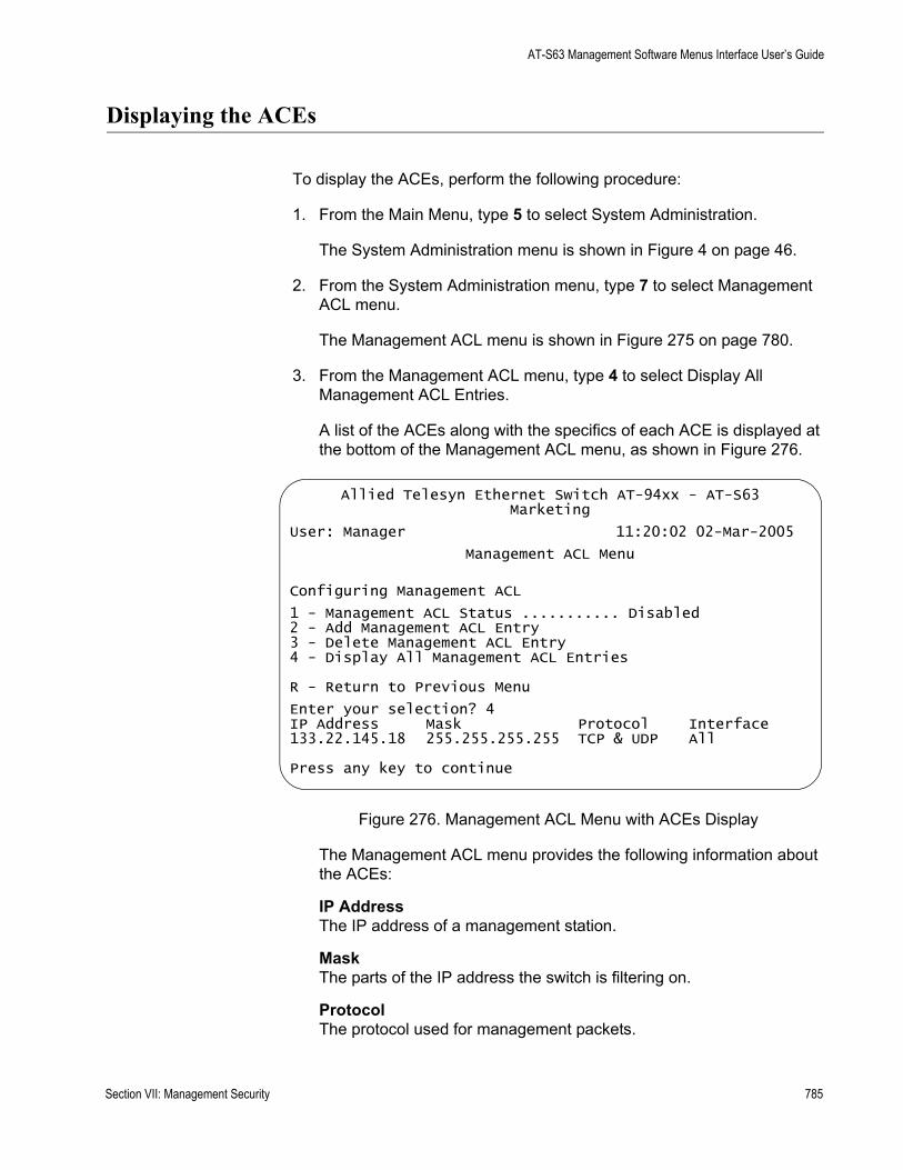
AT-S63 Management Software Menus Interface User’s Guide
Displaying the ACEs
To display the ACEs, perform the following procedure:
1. From the Main Menu, type 5 to select System Administration.
The System Administration menu is shown in Figure 4 on page 46.
2. From the System Administration menu, type 7 to select Management ACL menu.
The Management ACL menu is shown in Figure 275 on page 780.
3. From the Management ACL menu, type 4 to select Display All Management ACL Entries.
A list of the ACEs along with the specifics of each ACE is displayed at the bottom of the Management ACL menu, as shown in Figure 276.
Figure 276. Management ACL Menu with ACEs Display
The Management ACL menu provides the following information about the ACEs:
IP AddressThe IP address of a management station.
MaskThe parts of the IP address the switch is filtering on.
ProtocolThe protocol used for management packets.
Allied Telesyn Ethernet Switch AT-94xx - AT-S63Marketing
User: Manager 11:20:02 02-Mar-2005
Management ACL Menu
Configuring Management ACL
1 - Management ACL Status ........... Disabled2 - Add Management ACL Entry3 - Delete Management ACL Entry4 - Display All Management ACL Entries
R - Return to Previous Menu
Enter your selection? 4IP Address Mask Protocol Interface133.22.145.18 255.255.255.255 TCP & UDP All
Press any key to continue
Section VII: Management Security 785

Chapter 35: Management Access Control Lists
InterfaceThe interface that the management station uses to manage the switch. The options are Telnet, Web, and All (both Telnet and Web.)
786 Section VII: Management Security
Appendix A
AT-S63 Default Settings
This appendix lists the AT-S63 factory default settings. It contains the following sections in alphabetical order:
“Basic Switch Default Settings” on page 788“Enhanced Stacking Default Setting” on page 791“SNMP Default Settings” on page 792“Port Configuration Default Settings” on page 793“Event Log Default Settings” on page 794“Quality of Service” on page 795“IGMP Snooping Default Settings” on page 796“Denial of Service Prevention Default Settings” on page 797“STP, RSTP, and MSTP Default Settings” on page 798“VLAN Default Settings” on page 800“GVRP Default Settings” on page 801“Port Security Default Settings” on page 802“802.1x Port-Based Network Access Control Default Settings” on page 803“Web Server Default Settings” on page 804“SSL Default Settings” on page 805“PKI Default Settings” on page 806“SSH Default Settings” on page 807“Server-Based Authentication Default Settings” on page 808“Management Access Control List Default Setting” on page 809
787

Appendix A: AT-S63 Default Settings
Basic Switch Default Settings
This section lists the default settings for basic switch parameters. The following topics are covered:
“Boot Configuration File Default Setting” on page 788“Management Access Default Settings” on page 788“Management Interface Default Settings” on page 788“RJ-45 Serial Terminal Port Default Settings” on page 789“SNTP Default Settings” on page 789“Switch Administration Default Settings” on page 790“System Software Default Settings” on page 790
BootConfiguration
File DefaultSetting
The following table lists the File menu default setting.
ManagementAccess Default
Settings
The following table lists the management access default settings.
ManagementInterface Default
Settings
The following table lists the management interface default settings.
File Menu Setting Default
Default Configuration File boot.cfg
Remote Management Access Setting Default
Telnet Enabled
SNMP Disabled
TFTP Enabled
Web Server Enabled
Management Interface Setting Default
Manager Login Name manager
Manager Password friend
Operator Login Name operator
Operator Password operator
Console Disconnect Timer Interval 10 minutes
788 Section I: Basic Features
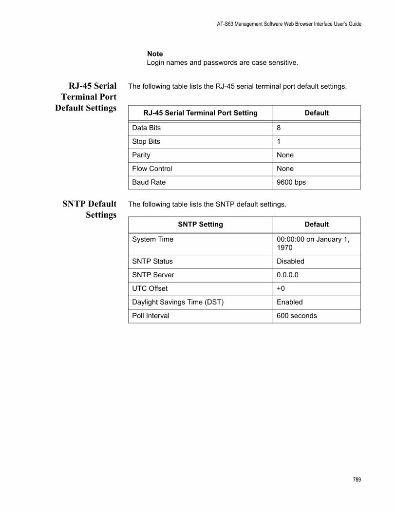
AT-S63 Management Software Web Browser Interface User’s Guide
NoteLogin names and passwords are case sensitive.
RJ-45 SerialTerminal Port
Default Settings
The following table lists the RJ-45 serial terminal port default settings.
SNTP DefaultSettings
The following table lists the SNTP default settings.
RJ-45 Serial Terminal Port Setting Default
Data Bits 8
Stop Bits 1
Parity None
Flow Control None
Baud Rate 9600 bps
SNTP Setting Default
System Time 00:00:00 on January 1, 1970
SNTP Status Disabled
SNTP Server 0.0.0.0
UTC Offset +0
Daylight Savings Time (DST) Enabled
Poll Interval 600 seconds
789
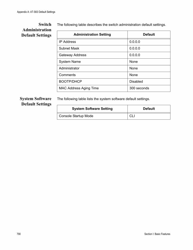
Appendix A: AT-S63 Default Settings
SwitchAdministrationDefault Settings
The following table describes the switch administration default settings.
System SoftwareDefault Settings
The following table lists the system software default settings.
Administration Setting Default
IP Address 0.0.0.0
Subnet Mask 0.0.0.0
Gateway Address 0.0.0.0
System Name None
Administrator None
Comments None
BOOTP/DHCP Disabled
MAC Address Aging Time 300 seconds
System Software Setting Default
Console Startup Mode CLI
790 Section I: Basic Features
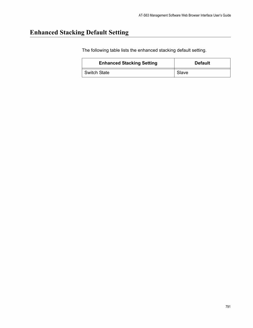
AT-S63 Management Software Web Browser Interface User’s Guide
Enhanced Stacking Default Setting
The following table lists the enhanced stacking default setting.
Enhanced Stacking Setting Default
Switch State Slave
791
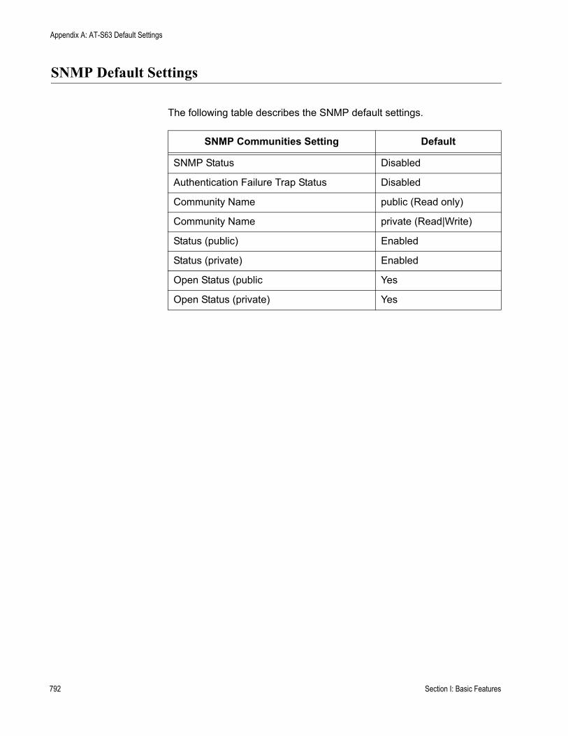
Appendix A: AT-S63 Default Settings
SNMP Default Settings
The following table describes the SNMP default settings.
SNMP Communities Setting Default
SNMP Status Disabled
Authentication Failure Trap Status Disabled
Community Name public (Read only)
Community Name private (Read|Write)
Status (public) Enabled
Status (private) Enabled
Open Status (public Yes
Open Status (private) Yes
792 Section I: Basic Features

AT-S63 Management Software Web Browser Interface User’s Guide
Port Configuration Default Settings
The following table lists the port configuration default settings.
Port Configuration Setting Default
Status Enabled
Broadcast Filter Disabled
Override Priority No override
HOL Blocking Disabled
Back Pressure Disabled
Flow Control Auto
Flow Control/Back Pressure Limit 7935
Speed Auto-Negotiation
Duplex Mode Auto-Negotiation
MDI/MDI-X Auto-MDI/MDIX
793
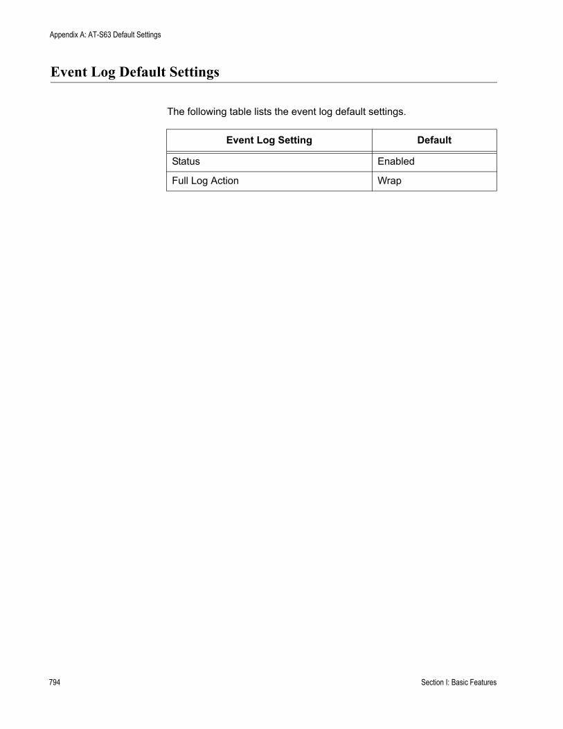
Appendix A: AT-S63 Default Settings
Event Log Default Settings
The following table lists the event log default settings.
Event Log Setting Default
Status Enabled
Full Log Action Wrap
794 Section I: Basic Features
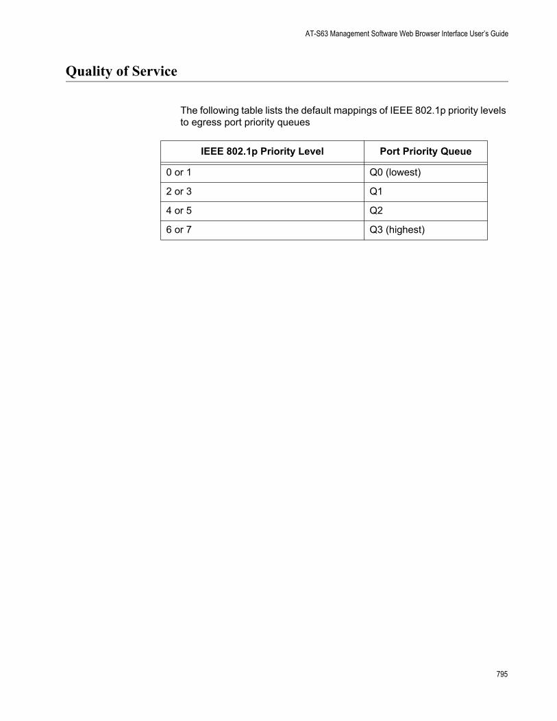
AT-S63 Management Software Web Browser Interface User’s Guide
Quality of Service
The following table lists the default mappings of IEEE 802.1p priority levels to egress port priority queues
IEEE 802.1p Priority Level Port Priority Queue
0 or 1 Q0 (lowest)
2 or 3 Q1
4 or 5 Q2
6 or 7 Q3 (highest)
795
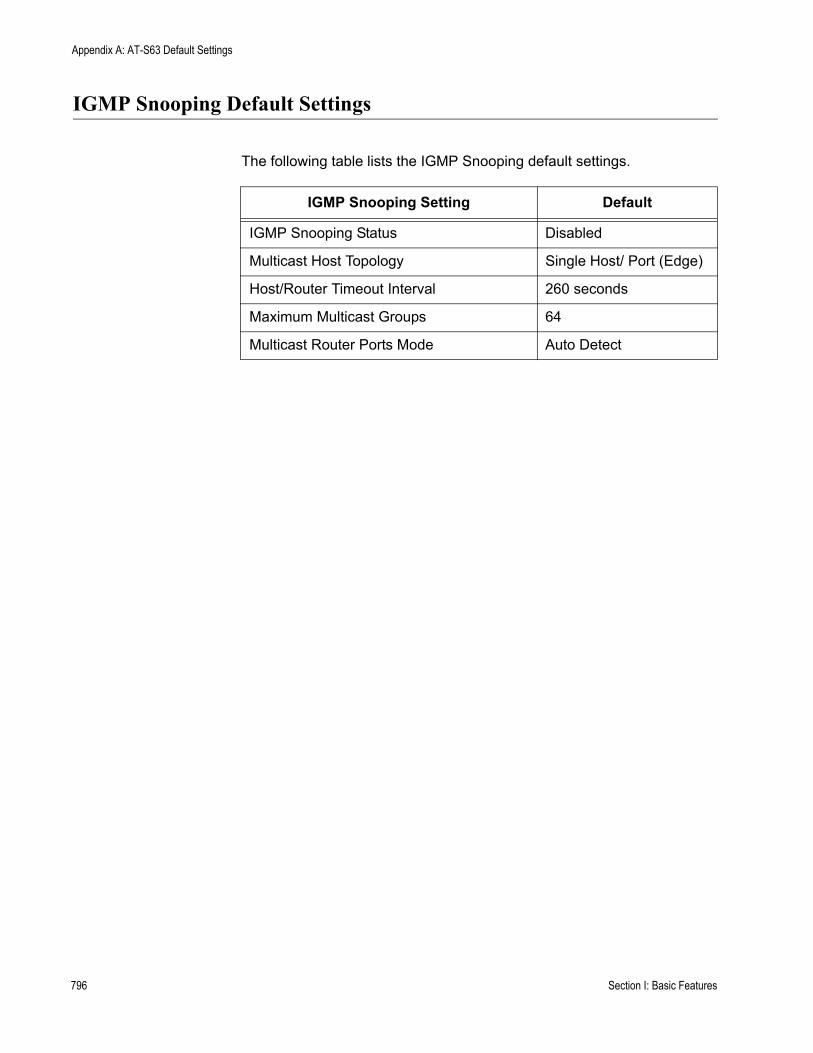
Appendix A: AT-S63 Default Settings
IGMP Snooping Default Settings
The following table lists the IGMP Snooping default settings.
IGMP Snooping Setting Default
IGMP Snooping Status Disabled
Multicast Host Topology Single Host/ Port (Edge)
Host/Router Timeout Interval 260 seconds
Maximum Multicast Groups 64
Multicast Router Ports Mode Auto Detect
796 Section I: Basic Features

AT-S63 Management Software Web Browser Interface User’s Guide
Denial of Service Prevention Default Settings
The following table lists the default settings for the Denial of Service prevention feature.
Denial of Service Prevention Setting Default
IP Address 0.0.0.0
Subnet Mask 0.0.0.0
Uplink Port 26
SYN Flood Defense Disabled
Smurf Defense Disabled
Land Defense Disabled
Teardrop Defense Disabled
Ping of Death Defense Disabled
IP Options Defense Disabled
797
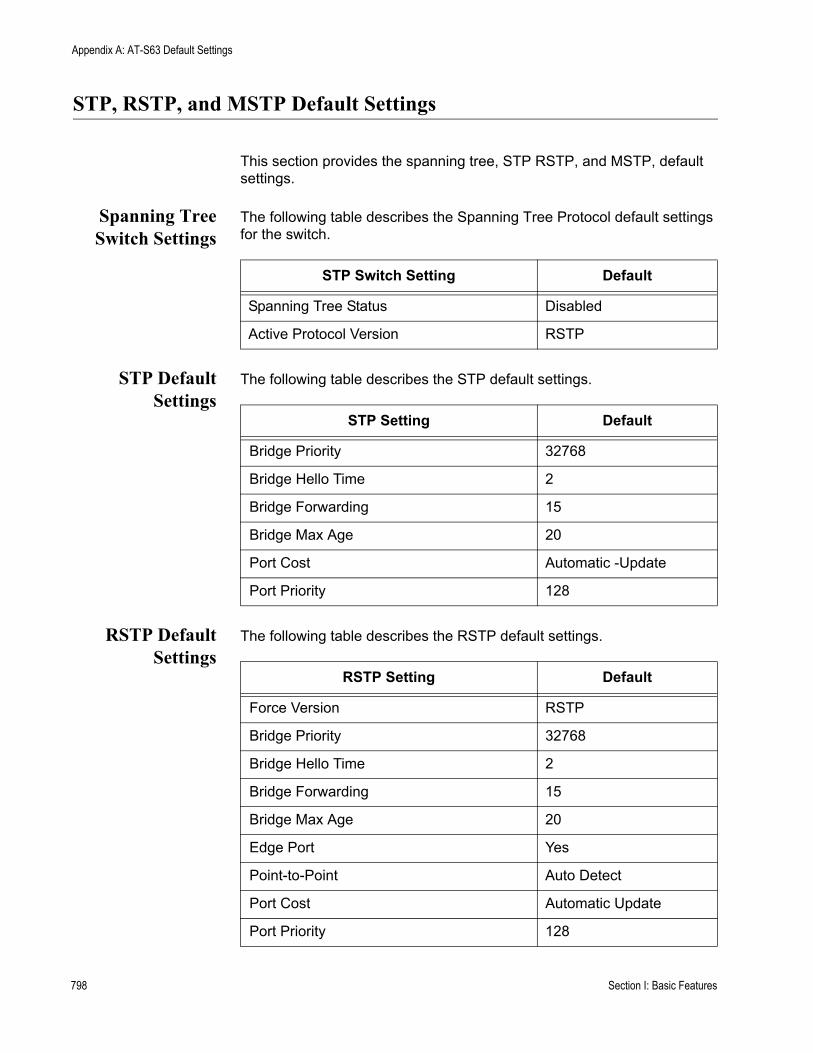
Appendix A: AT-S63 Default Settings
STP, RSTP, and MSTP Default Settings
This section provides the spanning tree, STP RSTP, and MSTP, default settings.
Spanning TreeSwitch Settings
The following table describes the Spanning Tree Protocol default settings for the switch.
STP DefaultSettings
The following table describes the STP default settings.
RSTP DefaultSettings
The following table describes the RSTP default settings.
STP Switch Setting Default
Spanning Tree Status Disabled
Active Protocol Version RSTP
STP Setting Default
Bridge Priority 32768
Bridge Hello Time 2
Bridge Forwarding 15
Bridge Max Age 20
Port Cost Automatic -Update
Port Priority 128
RSTP Setting Default
Force Version RSTP
Bridge Priority 32768
Bridge Hello Time 2
Bridge Forwarding 15
Bridge Max Age 20
Edge Port Yes
Point-to-Point Auto Detect
Port Cost Automatic Update
Port Priority 128
798 Section I: Basic Features
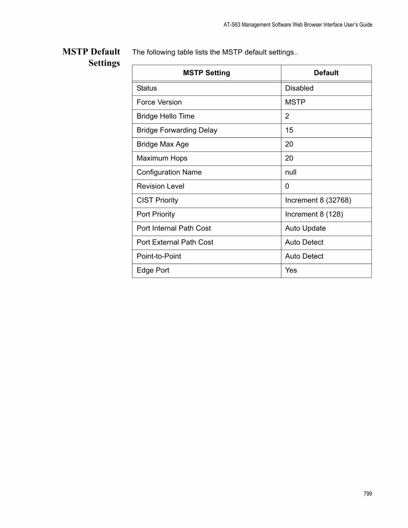
AT-S63 Management Software Web Browser Interface User’s Guide
MSTP DefaultSettings
The following table lists the MSTP default settings..
MSTP Setting Default
Status Disabled
Force Version MSTP
Bridge Hello Time 2
Bridge Forwarding Delay 15
Bridge Max Age 20
Maximum Hops 20
Configuration Name null
Revision Level 0
CIST Priority Increment 8 (32768)
Port Priority Increment 8 (128)
Port Internal Path Cost Auto Update
Port External Path Cost Auto Detect
Point-to-Point Auto Detect
Edge Port Yes
799
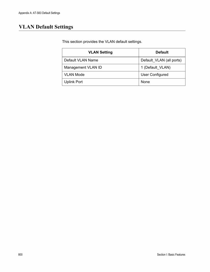
Appendix A: AT-S63 Default Settings
VLAN Default Settings
This section provides the VLAN default settings.
VLAN Setting Default
Default VLAN Name Default_VLAN (all ports)
Management VLAN ID 1 (Default_VLAN)
VLAN Mode User Configured
Uplink Port None
800 Section I: Basic Features
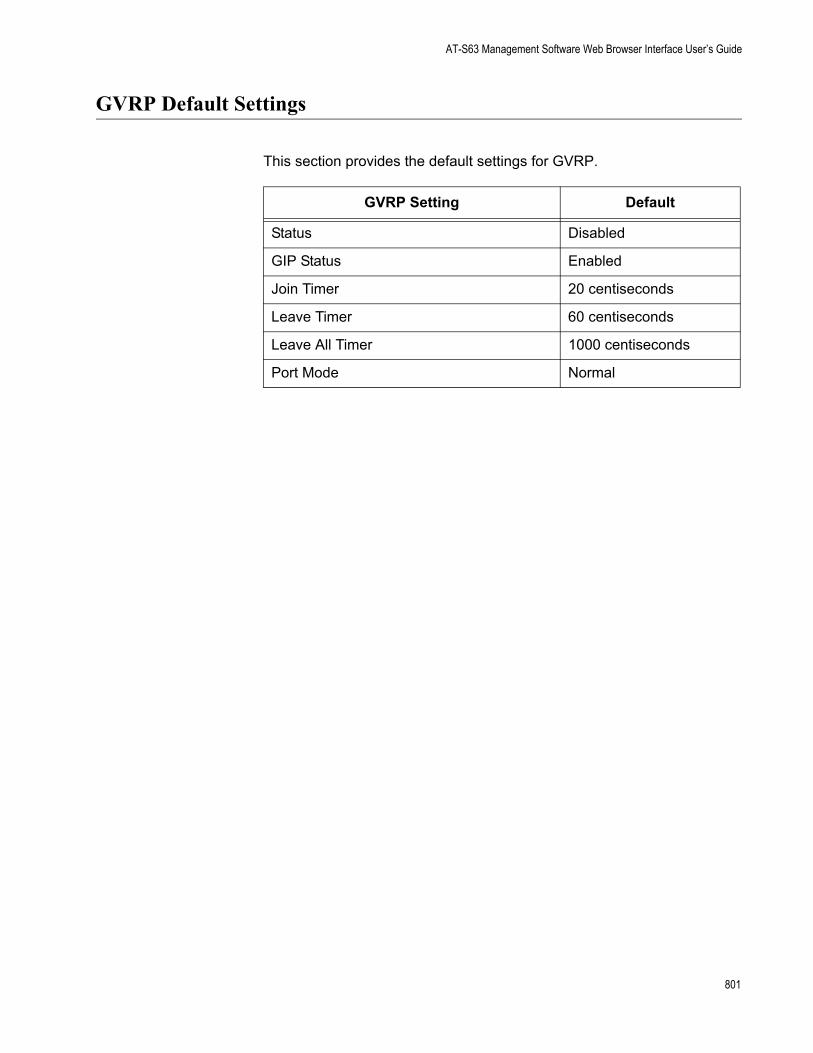
AT-S63 Management Software Web Browser Interface User’s Guide
GVRP Default Settings
This section provides the default settings for GVRP.
GVRP Setting Default
Status Disabled
GIP Status Enabled
Join Timer 20 centiseconds
Leave Timer 60 centiseconds
Leave All Timer 1000 centiseconds
Port Mode Normal
801

Appendix A: AT-S63 Default Settings
Port Security Default Settings
The following table lists the port security default settings.
Port Security Setting Default
Security Mode Automatic (no security)
Intrusion Action Discard
Participating No
MAC Limit No Limit
802 Section I: Basic Features

AT-S63 Management Software Web Browser Interface User’s Guide
802.1x Port-Based Network Access Control Default Settings
The following table describes the 802.1x Port-based Network Access Control default settings.
The following table lists the default settings for RADIUS accounting.
802.1x Port-based Network Access Control Settings Default
Port Access Control Disabled
Authentication Method RADIUS EAP
Port Role None
RADIUS Accounting Settings Default
Status Disabled
Port 1813
Type Network
Trigger Type Start_Stop
Update Status Disabled
Update Interval 60
803
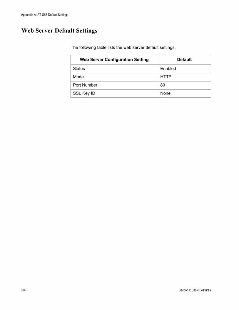
Appendix A: AT-S63 Default Settings
Web Server Default Settings
The following table lists the web server default settings.
Web Server Configuration Setting Default
Status Enabled
Mode HTTP
Port Number 80
SSL Key ID None
804 Section I: Basic Features
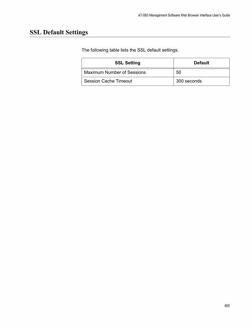
AT-S63 Management Software Web Browser Interface User’s Guide
SSL Default Settings
The following table lists the SSL default settings.
SSL Setting Default
Maximum Number of Sessions 50
Session Cache Timeout 300 seconds
805

Appendix A: AT-S63 Default Settings
PKI Default Settings
The following table lists the PKI default settings, including the generate enrollment request settings.
PKI Setting Default
Switch Distinguished Name None
Maximum Number of Certificates 256
Request Name None
Key Pair ID 0
Format PEM
Type PKCS10
806 Section I: Basic Features
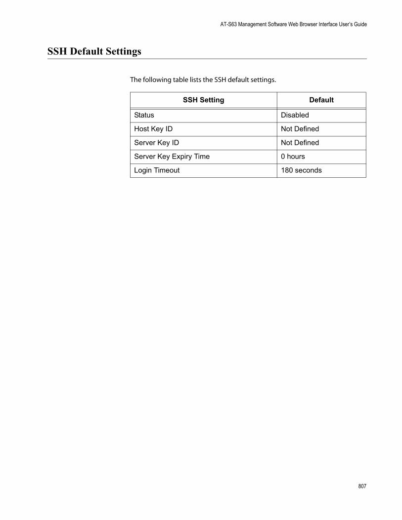
AT-S63 Management Software Web Browser Interface User’s Guide
SSH Default Settings
The following table lists the SSH default settings.
SSH Setting Default
Status Disabled
Host Key ID Not Defined
Server Key ID Not Defined
Server Key Expiry Time 0 hours
Login Timeout 180 seconds
807
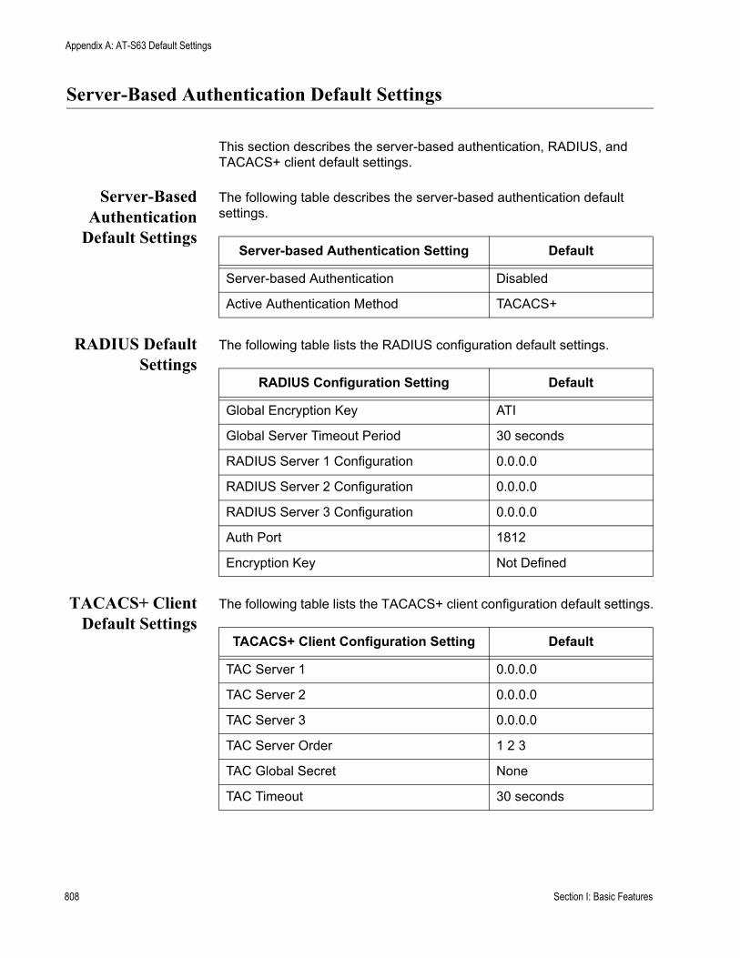
Appendix A: AT-S63 Default Settings
Server-Based Authentication Default Settings
This section describes the server-based authentication, RADIUS, and TACACS+ client default settings.
Server-BasedAuthentication
Default Settings
The following table describes the server-based authentication default settings.
RADIUS DefaultSettings
The following table lists the RADIUS configuration default settings.
TACACS+ ClientDefault Settings
The following table lists the TACACS+ client configuration default settings.
Server-based Authentication Setting Default
Server-based Authentication Disabled
Active Authentication Method TACACS+
RADIUS Configuration Setting Default
Global Encryption Key ATI
Global Server Timeout Period 30 seconds
RADIUS Server 1 Configuration 0.0.0.0
RADIUS Server 2 Configuration 0.0.0.0
RADIUS Server 3 Configuration 0.0.0.0
Auth Port 1812
Encryption Key Not Defined
TACACS+ Client Configuration Setting Default
TAC Server 1 0.0.0.0
TAC Server 2 0.0.0.0
TAC Server 3 0.0.0.0
TAC Server Order 1 2 3
TAC Global Secret None
TAC Timeout 30 seconds
808 Section I: Basic Features

AT-S63 Management Software Web Browser Interface User’s Guide
Management Access Control List Default Setting
The following table lists the default setting for the Management Access Control List.
Management ACL Setting Default
Status Disabled
809

Appendix A: AT-S63 Default Settings
810 Section I: Basic Features

Index
Numerics802.1x Port-based Network Access Control
access role, configuring 657authentication process 649authenticator port
configuring 660described 649
configuring 657default settings 803disabling 659enabling 659guidelines 654overview 648port parameters, displaying 667port role, configuring 657port roles 650supplicant port
configuring 664described 648
Aaccess control entry (ACE)
adding 783deleting 784described 776displaying 785parts of 776
access control listactions 270creating 277deleting 282deleting all 284described 270displaying 285examples 272modifying 280
ACE. See access control entry (ACE)ACL. See access control list (ACL)Address Resolution Protocol (ARP) table
configuring timeout value 168defined 164deleting an entry 166
administrator nameconfiguring 48default setting 790
adminkey parameterdescribed 131setting 146, 149
aggregate trunk, described 128
aggregatorcreating 145deleting 149described 128displaying status 151modifying 147
aging timechanging 682default setting 790defined 673
app (applicant state machine) parameter 608ARP. See Address Resolution Protocol (ARP) table 164associated VLANs parameter 523associations
defined 507VLANs to MSTI IDs 527
asymmetrical encryption algorithms 701AT-9400 Series switch, hardware information 51AT-S63 software
default settings 787resetting to factory defaults 67
AT-S63 software updatesdownloading from a local session 206obtaining 26
authentication failure trapdisabling 80enabling 80
authentication failure trap, default setting 792authentication protocols 762authentication server 649authenticator port role 650authenticator port, described 649automatic port security mode, described 638autonegotiation
configuring 104forced 117status 124
Bback pressure
default setting 793described 109
baud rate, terminal port 65boot configuration file
configuring parameters 185creating 183displaying 187editing 188overview 183
811

Index
selecting 186selecting active 186
Boot Protocol (BootP)activating 49deactivating 49default setting 790defined 49
BPDU. See bridge protocol data unitbridge forwarding delay
default setting 798, 799Multiple Spanning Tree Protocol (MSTP) 518Rapid Spanning Tree Protocol (RSTP) 494Spanning Tree Protocol (STP) 488
bridge hello timedefault setting 798Multiple Spanning Tree Protocol (MSTP) 517Rapid Spanning Tree Protocol (RSTP) 494Spanning Tree Protocol (STP) 488
bridge identifierdescribed 477Multiple Spanning Tree Protocol (MSTP) 518Rapid Spanning Tree Protocol (RSTP) 494Spanning Tree Protocol (STP) 488
bridge max agedefault setting 798Multiple Spanning Tree Protocol (MSTP) 518Rapid Spanning Tree Protocol (RSTP) 494Spanning Tree Protocol (STP) 488
bridge prioritydefault setting 798described 477Rapid Spanning Tree Protocol (RSTP) 494Spanning Tree Protocol (STP) 488
bridge protocol data unit (BPDU) 481, 488, 494broadcast filter, default setting 793
CCA certificate, steps for 690CA. See certification authority (CA)CBC. See Cipher Block Chaining (CBC)certificate database 728certificate database, PKI 748certificate format 745certificate revocation list (CRL), described 727certificate type, configuring 735certificates, guidelines 723certificates, PKI
adding to database 733chains 727creating 729database 728database storage 728deleting 736, 739described 725displaying 741installing 747modifying 736, 739validating 727
certificates, SSL
authenticating 698described 699
certificates, X.509 725certification authority (CA)
described 726root 727
CFB. See Cipher Feedback (CFB)Cipher Block Chaining (CBC), described 701Cipher Feedback (CFB), described 701ciphers available parameter 760CIST priority parameter 520CIST. See Common and Internal Spanning TreeClass of Service (CoS)
configuring 343described 338mapping to egress queues 346priority level and egress queue mappings 338scheduling, configuring 348
classifiercomponents of 253creating 259defined 252deleting 265displaying 266guidelines 258modifying 263
Common and Internal Spanning Tree (CIST)configuring 520defined 511priority 511priority, displaying 522
community nameSNMPv1 and SNMPv2c 76SNMPv3 protocol 457
compact flash cardchanging directory on 203displaying information about 201listing files on 197
compact flash card slot, described 201configuration file
default name 788downloading switch to switch 214
configuration name 508, 518console disconnect interval
configuring 63default setting 788
console startup modeconfiguring 62default setting 790
console timer 63CoS. See Class of Service (CoS)CRL. See certificate revocation list (CRL)
Ddata authentication, described 702data compression parameter 760Data Encryption Standard (DES), described 700data encryption, described 700daylight savings time (DST)
812

AT-S63 Management Software Menus Interface User’s Guide
default setting 789setting 60
default values, AT-S63 software 787default VLAN name 550defined 253Denial of Service (DoS) defense
configuring 293default settings 797mirror port 295overview 288
DER certificate format 732, 745DES privacy protocol 371DES. See Data Encryption Standard (DES)destination IP address 134, 256destination IP mask 256destination MAC address 134, 253destination port 156Diffie-Hellman algorithm 704DiffServ domain 255digital certificates. See certificatesdigital signatures 724distinguished name
configuring 732default setting 806described 721
DoS. See Denial of Service (DoS) defenseDSCP value 255duplex mode
configuring 124default setting 793
dynamic GVRP port 584dynamic GVRP VLAN 584Dynamic Host Control Protocol (DHCP)
activating 49deactivating 49default setting 790
dynamic MAC address, defined 672
EECB. See Electronic Code Book (ECB)edge port
default setting 798, 799described 481Multiple Spanning Tree Protocol (MSTP) 534Rapid Spanning Tree Protocol (RSTP) 496
edge port parameter 534egress rules 579Electronic Code Book (ECB), described 700encryption (SSL) 697encryption key
creating 705deleting 709described 694displaying 717exporting 711importing 714modifying 710Secure Shell (SSH) 752
End Entity 726
Engine ID, defined 371enhanced stacking
and SSH 753configuring 93default switch setting 791defined 44, 90diagram 92guidelines 90returning to master switch 98selecting switch 95setting switch status 93
enrollment requestcreating 744name, configuring 745steps for 690
entities, defined 370ethernet format 253Ethernet port statistics
clearing 122displaying 119
event logclearing 238default settings 794disabling 230displaying 232enabling 230overview 228saving to a file 238severity codes 236software module list 233
Ffacility levels 244factory defaults
list 787resetting 67
fan speed 70file naming conventions 180file system, description 180files, upoading 222filtering, configuring 112flash memory
displaying information about 199formatting 199
flow controldefault setting 793described 109
flow groupcreating 313decribed 299deleting 317displaying 318modifying 315
force renegotiation, configuring 117force version
default setting 798, 799Multiple Spanning Tree Protocol (MSTP) 517Rapid Spanning Tree Protocol (RSTP) 494
forwarding delay 480
813

Index
GGARP Information Declaration (GID), diagram 590GARP Information Propagation (GIP)
connected ports ring, displaying 604defined 588
GARP VLAN Registration Protocol (GVRP)configuring 592counters, displaying 597database, displaying 602default settings 801diagram 585disabling on a port 594displaying
GVRP state machine 606parameters 597, 602, 604, 606statistics 597, 602, 604, 606
enabling on a port 594GIP connected ports ring, displaying 604guidelines 586GVRP state machine, displaying 606intermediate switches 587overview 584parameters, displaying 597, 602port configuration, displaying 596security issues 587statistics, displaying 597, 602
GARP. See Generic Attribute Registration Protocol (GARP)gateway address
configuring 47default setting 790
GBIC transceiver, displaying information about 71Generic Attribute Registration Protocol (GARP)
Applicant state machine 590defined 588diagram 589overview 587Registrar state machine 590
GID index parameter 602GID. See GARP Information Declaration (GID)GIP. See GARP Information Propagation (GIP)global encryption key
configuring 771default setting 808
global secretconfiguring 768default setting 808displaying 769
global server timeoutconfiguring 771default setting 808
GVRP database 602GVRP join timer 593GVRP leave all timer 593GVRP leave timer parameter 593GVRP status 592GVRP. See GARP VLAN Registration Protocol (GVRP)
Hhardware information 51hash algorithm 702hello time
default setting 798described 481Multiple Spanning Tree Protocol (MSTP) 517Rapid Spanning Tree Protocol (RSTP) 494Spanning Tree Protocol (STP) 488
HMAC authentication algorithm 703HMAC-MD5-96 (MD5) authentication protocol 371HMAC-SHA-96 (SHA) authentication protocol 371HOL blocking
configuring 107default setting 793
host key ID parameter 757host/router timeout interval
configuring 355default setting 796
HTTP 686HTTPS 686
IIEEE 802.1D standard 475IEEE 802.1p standard 338IEEE 802.1w standard 493IGMP snooping status, default setting 796image file, downloading 210ingress filtering, enabling or disabling 580ingress packet threshold 114ingress rules 579inner CBC encryption mode 701Internet Group Management Protocol (IGMP) snooping
configuring 354default setting 796disabling 357displaying
host nodes 358multicast routers 360
enabling 357host nodes, displaying 358multicast routers, displaying 360snoop topology 355
Internet Protocol (IP) addressassigning 45configuring 47default 790switches 44
intrusion action (port)configuring 642default setting 802
IP Options attack 291
Kkey exchange algorithms 703key pair ID, configuring 745
814

AT-S63 Management Software Menus Interface User’s Guide
LLACP port priority
described 131LACP system priority
configuring 144described 131
LACP trunkconfiguring ports 150creating aggregator 145deleting aggregator 149described 128displaying status 151enabling or disabling protocol 143guidelines 133modifying aggregator 147
Land attack 289limited port security mode, described 638Link Aggregation Control Protocol. See LACP trunklink status 123load distribution methods
described 134setting in LACP trunk 146, 149setting in static port trunk 138, 140
local management sessiondefined 30quitting 40starting 38
locked port security mode, described 639log output definition
creating 241deleting 248described 241displaying 249facility levels 244modifying 247
login timeout parameter 757
MMAC address aging time
changing 682default setting 790
MAC address tabledefined 672displaying 674
MAC addressesadding 678defined 672deleting 680displaying 674
MAC limit, default setting 802MAC. See Message Authentication Code (MAC)MACs available parameter 760Main Menu 40, 42management access defaults 788management access levels 33, 55management ACL
creating 780default setting 809
described 776guidelines 777
Management Information Base. See MIBsmanagement interface defaults 788management VLAN ID
configuring 582default setting 800
management VLAN, described 581manager access 33, 55manager accounts 762manager password
configuring 55default setting 788
master switchassigning 93defined 93returning to 98
max agedefault setting 798Multiple Spanning Tree Protocol (MSTP) 518Rapid Spanning Tree Protocol (RSTP) 494Spanning Tree Protocol (STP) 488
max hops, Multiple Spanning Tree Protocol (MSTP) 518maximum multicast groups
configuring 356default setting 796
maximum number of sessionsconfiguring 749default setting 805
MCHECK 497MD5 authentication algorithm 703MD5 authentication protocol 371MDI, configuring 124MDI/MDI-X, configuring 105MDI-X, configuring 124message authentication code (MAC)
defined 697described 702
message encryption 724MIB subtree view 372MIB tree
diagram 372RFC 372
MIB view 372MIBs
supported 31viewing 370
MSTI association to a VLANcreating 528removing 529
MSTI IDassociating to VLANs 530creating 524deleting 525list 522modifying 525removing a VLAN association 530
MSTI priority, defined 510MSTI. See Multiple Spanning Tree Instance (MSTI)
815

Index
MSTP. See Multiple Spanning Tree Protocol (MSTP)multicast groups, maximum 356multicast host topology
configuring 355default setting 796
multicast MAC addressadding 678deleting 680, 681displaying 674
multicast router portsconfiguring 356default setting 796
Multiple Spanning Tree Instance (MSTI)defined 503diagram 506guidelines 507MSTI ID
associating to VLANs 530creating 524deleting 525list 522modifying 525removing a VLAN association 530
port priority 522Multiple Spanning Tree Protocol (MSTP)
activating 516associating VLANs to MSTI IDs 527associations 507bridge forwarding delay 518bridge hello time 517bridge identifier 518bridge max age 518bridge settings, configuring 517configuration name 508, 518connecting VLANs 514default settings 799diagram 505edge port 534force version 517max hops 518MSTI ID, modifying 525MSTI priority, defined 510overview 502point-to-point port 534port configuration, displaying 538port external path cost 534port internal path cost 536port parameters, configuring 532port priority 536port status, displaying 540regional root 510regions 507, 508resetting to defaults 543revision level 518revision number 508with STP and RSTP 511
multiple VLAN802.1Q-compliant 612defined 612
modeactivating 616deactivating 616
overview 612
Nnegotiation status 124networking stack 163non-802.1Q compliant multiple VLAN mode, described 614none port role 650nonvolatile storage, described 373
OOFB. See Output Feedback (OFB)operator access 33, 55operator password
configuring 55default setting 788
outer CBC encryption mode 701Output Feedback (OFB), described 701override priority, default setting 793
Ppacket filtering, configuring 112password, default 39path cost 523path cost, desciption 478PEM certificate format 732, 745Ping of Death attack 291pinging 66PKI certificates
adding to database 733certificate database 728chains 727creating 729database storage 728described 725displaying 741maximum number of certificates, default setting 806modifying 736validating 727
PKI. See Public Key Infrastructure (PKI)point-to-point (port) parameter 534point-to-point port
default setting 798described 481Multiple Spanning Tree Protocol (MSTP) 534Rapid Spanning Tree Protocol (RSTP) 496
policycreating 330deleting 333described 300displaying 334guidelines 300modifying 332
poll intervaldefault setting 789setting 61
port
816

AT-S63 Management Software Menus Interface User’s Guide
default configuration 118disabling 103enabling 103resetting 116, 118speed, 105status
default setting 793displaying 123
port costdescription 478Rapid Spanning Tree Protocol (RSTP) 496Spanning Tree Protocol (STP) 490
port costdefault setting 798, 799port external path cost parameter, Multiple Spanning Tree
Protocol (MSTP) 534port internal path cost, Multiple Spanning Tree Protocol
(MSTP) 536port mirror
creating 157deleting 159destination port 156displaying 161modifying 160source port 156
port mirroring, described 156port mode 595port parameters, configuring
general 102Multiple Spanning Tree Protocol (MSTP) 532Rapid Spanning Tree Protocol (RSTP) 495Spanning Tree Protocol (STP) 489
port priorities, displaying 350port priority
default setting 798described 479displaying 578Multiple Spanning Tree Instance (MSTI) 522Multiple Spanning Tree Protocol (MSTP) 536Rapid Spanning Tree Protocol (RSTP) 496Spanning Tree Protocol (STP) 490
port role, default setting 803port security
configuring 641default settings 802defined 638displaying 644guidelines 640intrusion action 642levels 638
port security violations 639port speed
configuring 124default setting 793
port statisticsclearing 122displaying 119
port trunkingexample 126
port VLAN identifier (PVID)
described 551displaying 350, 578
port-based access control. See 802.1x Port-based Network Access Control
port-based VLANcreating 561, 565, 623creating, example 565defined 550deleting 573diagram 553displaying 571, 617drawbacks 552modifying 567rules 551
ports, untagged 551power supply status 70priority level and egress queue mappings 338privacy 371private keys 724protected ports VLAN
creating 623deleting 632described 620displaying 630guidelines 621modifying 626VLAN name, configuring 623
public key encryption 724Public Key Infrastructure (PKI)
certificate database 728, 748certificates
adding 728adding to database 733chains 727creating 729deleting 739displaying 741fingerprint 728format 732modifying 736retrieving 728validating 727
certification authority (CA)described 726root 727
default settings 806End Entity 726overview 724standards 728structure 726X.509 certificates 725
PVID. See Port VLAN identifier (PVID)
QQoS. See Quality of Service (QoS)Quality of Service (QoS)
default settings 795described 298, 338scheduling
817

Index
configuring 346described 340
See also traffic class, flow group, and policy
RRADIUS
configuring 771default settings 808disabling 766displaying settings 773enabling 765guidelines 763overview 762settings, displaying 773status, displaying 773
RADIUS accounting, configuring 669RADIUS server
encryption key 772IP address, configuring 772
Rapid Spanning Tree Protocol (RSTP)bridge forwarding delay 494bridge hello time 494bridge max age 494bridge parameters, configuring 493bridge priority 494default settings 798disabling 485edge port, configuring 496enabling 485force version 494MCHECK 497point-to-point port, configuring 496port configuration, displaying 497port cost 496port parameters, configuring 495port priority 496port state, displaying 498resetting to defaults 500
rate limit, setting 114redundant power supply (RPS) status 70reg (registrar state machine) 609regional root ID 522regional root path cost 523regional root, described 510remote management access defaults 788remote management session
defined 31quitting 42
rempte management sessionstarting 41
revision level 518revision number 508RJ-45 serial terminal port, default settings 789root bridge 477routing table 169RRP snooping
described 364disabling 366enabling 366
RSTP. See Rapid Spanning Tree Protocol (RSTP)
Sscheduling
configuring 346, 348described 340strict priority
configuring 348described 341
weighted round robinconfiguring 348described 341
Secure Shell (SSH)and enhanced stacking 753AT-S63 implementation 752ciphers 752clients, described 753configuration overview 755default settings 807encryption algorithms 752encryption keys 752overview 752server
configuring 756described 753displaying information 759
usersadding 753deleting 753modifying 753
Secure Sockets Layer (SSL)certificates
authenticating 698described 699
configuring 749data transfer 698default settings 805encryption 697message types 698overview 695, 697session 698user verification 698
secured port security mode, described 639self-signed certificate
creating 690described 720
server authentication UDP portconfiguring 772default setting 808
server key expiry time parameter 757server key ID parameter 757server-based authentication method
default setting 803, 808setting 765
session cache timeoutconfiguring 749default setting 805
SFP transceiver, displaying information about 71SHA authentication algorithm 703
818

AT-S63 Management Software Menus Interface User’s Guide
SHA authentication protocol 371Simple Network Management Protocol. See SNMPSimple Network Time Protocol (SNTP)
configuring 58default setting 789servers 58
slave switchassigning 93defined 93
SMURF attack 288SNMP
default setting for remote management 788default settings 792
SNMP community stringaccess mode 76closed access status 77creating 81default 78default name 792disabling 79displaying 88enabling 79modifying 84name 76open access status 77operating status 77
SNMP managementdefault setting 792disabling 79enabling 79session, starting 31
SNMPv1 and SNMPv2cagent 370community name 76manager 370overview 76
SNMPv1 protocol 370SNMPv2c protocol 370SNMPv3 Access Table entry
creating 399deleting 403displaying 467modifying
notify view 409read view 405storage type 411write view name 408
SNMPv3 Access Table, described 376SNMPv3 community 455SNMPv3 Community Table entry
creating 456deleting 459displaying 471modifying
community name 460security name 462storage type 463transport tag 462
SNMPv3 Community Table, described 377
SNMPv3 Engine ID, defined 371SNMPv3 entities 370SNMPv3 Notify Table entry
creating 422deleting 424displaying 469modifying
notify tag 425storage type 427
SNMPv3 Notify Table, described 377SNMPv3 protocol
authentication protocols 371community name parameter 457Configure SNMPv3 Community Table 377Engine ID 371message notification 373MIB views 372overview 370privacy protocols 371SNMPv3 Access Table 376SNMPv3 Notify Table 377SNMPv3 SecurityToGroup Table 377SNMPv3 Target Address Table 377SNMPv3 Target Parameters Table 377storage types 373tables 374User Table 376View Table 376
SNMPv3 SecurityToGroup Table entrycreating 414deleting 417displaying 468modifying
group name 418storage type 420
SNMPv3 SecurityToGroup Table, described 377SNMPv3 Target Address Table entry
creating 429deleting 432displaying 470modifying
storage type 440target address retries 437target address tag list 438target address timeout 436target address UDP port 435target IP address 433target parameters 439
SNMPv3 Target Address Table, described 377SNMPv3 Target Parameters Table entry
creating 443deleting 446displaying 470modifying
message process model 452security level 450security model 449storage type 453user name 447
819

Index
SNMPv3 Target Parameters Table, described 377SNMPv3 trap 373SNMPv3 User Table entry
creating 380deleting 384displaying 465modifying
authentication protocol 385authentication protocol password 385privacy protocol 387privacy protocol password 387
SNMPv3 User Table, described 376SNMPv3 View Table entry 396
creating 390deleting 393displaying 466storage type, modifying 397subtree mask, modifying 394
SNMPv3 View Table, described 376SNTP server, default setting 789SNTP. See Simple Network Time Protocol (SNTP)software updates
downloading from a local session 206downloading switch to switch 212
source address (SA) trunking load distribution method 134source IP address 134, 256source IP mask 256source MAC address 253source port 156Spanning Tree Protocol (STP)
and VLANs 483bridge forwarding delay 488bridge hello time 488bridge identifier 488bridge max age 488bridge parameters, configuring 487bridge priority 488default settings 798defined 476disabling 485enabling 485forwarding delay 488port cost 490port settings, configuring 489port settings, displaying 491resetting to defaults 492
spanning tree, default setting 798SSH server status parameter 757SSH. See Secure Shell (SSH)SSL certificates
authenticating 698described 699
SSL key ID, configuring 688SSL messages 698SSL. See Secure Sockets Layer (SSL)static MAC address
adding 678deleting 681displaying 674
static port trunkcreating 136deleting 141described 126guidelines 127modifying 139
static unicast MAC addressadding 678defined 673deleting 680displaying 674
STP ID parameter 605STP. See Spanning Tree Protocol (STP)strict priority scheduling 341subnet mask
configuring 47default setting 790
subtree mask, related to MIB subtree view 372supplicant port, described 648supplicant role 651switch
hardware information, displaying 69rebooting 53
switch name, configuring 46switch state, default setting 791symmetrical encryption 700SYN Flood attack 288syslog server 241system date
default setting 789setting 58
system filescopying 190deleting 194display on compact flash card 197displaying 195downloading
filesdownloading 216
renaming 192uploading 222
system hardware information, displaying 69system information 51system name
configuring 48default setting 790
system software default settings 790system temperature 70system time
default setting 789setting 58
TTACACS+
configuring 767default settings 808disabling 766displaying settings 769
820

AT-S63 Management Software Menus Interface User’s Guide
enabling 765guidelines 763overview 762server IP address 767server order
configuring 768displaying 769
server timeoutconfiguring 768default setting 808displaying 770
tagged VLANcreating 561defined 556deleting 573diagram 559displaying 571, 617example 566modifying 567overview 556rules 558
target IP address 422TCP connections table 171TCP destination ports 257TCP flags 257TCP Global Information table 175TCP source ports 257Teardrop attack 290Telnet server, enabling or disabling 64Telnet, default setting for remote management 788terminal port baud rate, setting 65TFTP
default setting for remote management 788downloading and uploading files 206
traffic classcreating 320deleting 325described 300displaying 327modifying 324
traffic flow, defined 252trap receivers 77Triple DES (3DES) encryption algorithms, described 701Type of Service field 255
UUDP destinaton ports 257UDP source ports 257unavailable status, defined 93uplink port
configuring 616default setting 800described 614VLAN 613
uplink port information, displaying 71User-based Security Model (USM) authentication 370UTC offset
default setting 789setting 60
Vversions supported (SSH) parameter 759VID. See VLAN IDview type, modifying 396virtual LAN (VLAN)
creating 561, 565, 623default settings 800defined 548deleting 573, 576displaying 571, 617modifying 567multiple
802.1Q-compliant 612defined 612overview 612
overview 548port-based, defined 550tagged, defined 556
VLAN and MSTI associations 507VLAN ID
configuring 124, 568described 550
VLAN nameconfiguring 562default setting 800described 550protected ports VLAN 623
VLAN, port-based. See port-based VLANVLAN, tagged. See tagged VLANVLAN. See virtual LAN (VLAN)volatile storage 373
Wweb server
configuring 687default settings 804described 686disabling 688enabling 688overview 686
web server mode, configuring 688weighted round robin priority scheduling 341wildcards, in file names 181
XX.509
certificate 725specification 725
821

Index
822