mentor graphics vhdl reference manualpages.cs.wisc.edu/~sohi/cs552/handouts/mentordocs/... ·...
TRANSCRIPT

Mentor Graphics VHDLReference Manual
July 1994
Copyright 1991-1994 Mentor Graphics Corporation. All rights reserved.
Confidential. May be photocopied by licensed customers of
Mentor Graphics for internal business purposes only.

The software programs described in this document are confidential and proprietary products of MentorGraphics Corporation (Mentor Graphics) or its licensors. No part of this document may be photocopied,reproduced or translated, or transferred, disclosed or otherwise provided to third parties, without theprior written consent of Mentor Graphics.
The document is for informational and instructional purposes. Mentor Graphics reserves the right tomake changes in specifications and other information contained in this publication without prior notice,and the reader should, in all cases, consult Mentor Graphics to determine whether any changes havebeen made.
The terms and conditions governing the sale and licensing of Mentor Graphics products are set forth inthe written contracts between Mentor Graphics and its customers. No representation or otheraffirmation of fact contained in this publication shall be deemed to be a warranty or give rise to anyliability of Mentor Graphics whatsoever.
MENTOR GRAPHICS MAKES NO WARRANTY OF ANY KIND WITH REGARD TO THIS MATERIALINCLUDING, BUT NOT LIMITED TO, THE IMPLIED WARRANTIES OR MERCHANTABILITY ANDFITNESS FOR A PARTICULAR PURPOSE.
MENTOR GRAPHICS SHALL NOT BE LIABLE FOR ANY INCIDENTAL, INDIRECT, SPECIAL, ORCONSEQUENTIAL DAMAGES WHATSOEVER (INCLUDING BUT NOT LIMITED TO LOST PROFITS)ARISING OUT OF OR RELATED TO THIS PUBLICATION OR THE INFORMATION CONTAINED INIT, EVEN IF MENTOR GRAPHICS CORPORATION HAS BEEN ADVISED OF THE POSSIBILITY OFSUCH DAMAGES.
Portions of this manual are based on IEEE Std 1076-1987, IEEE Standard VHDL Language ReferenceManual, copyright 1988 by the Institute of Electrical and Electronics Engineers, Inc.. The IEEE doesnot, in whole or in part, endorse the contents of this manual. For information on purchasing the IEEEStandard, call 1-800-678-IEEE.
RESTRICTED RIGHTS LEGEND Use, duplication, or disclosure by the Government is subject torestrictions as set forth in subdivision (c)(1)(ii) of the Rights in Technical Data and Computer Softwareclause at DFARS 252.227-7013.
A complete list of trademark names appears in a separate "Trademark Information" document.
Mentor Graphics Corporation8005 S.W. Boeckman Road, Wilsonville, Oregon 97070.
Copyright Mentor Graphics Corporation 1993. All rights reserved.An unpublished work of Mentor Graphics Corporation.

Table of Contents________________________________________________________________________________________________________________________
TABLE OF CONTENTS
About This Manual xv
Section 1
Lexical Elements 1-1
Definition of Lexical Elements 1-3Character Set 1-5Replacement Characters 1-6Identifiers 1-8Reserved Words 1-9Comments 1-15Literals 1-15
Numeric Literals 1-15Character Literals 1-18String Literals 1-19Character and String Literal Differences 1-20Bit String Literals 1-20
Separators and Delimiters 1-21Separators 1-21Delimiters 1-22
Section 2
Expressions 2-1
Definition of Expressions 2-3General Expression Rules 2-4
Operands (Primaries) 2-6Names 2-6Literal 2-7Aggregates 2-8Function Calls 2-10Qualified Expressions 2-10Type Conversions 2-12
Mentor Graphics VHDL Reference Manual, July 1994 iii

Table of Contents________________________________________________________________________________________________________________________
TABLE OF CONTENTS [continued]
Section 2 Expressions [continued]
Allocators 2-13VHDL Predefined Operators 2-16
Important Notes About Operators 2-17Miscellaneous Operators 2-18Multiplying Operators 2-20Sign 2-22Adding Operators 2-23Shift Operators 2-28Relational Operators 2-28
Predefined Equality and Inequality Operators 2-29Predefined Ordering Operators 2-30
Logical Operators 2-31Static Expressions 2-32Universal Expressions 2-36
Section 3
Naming, Scope, and Visibility 3-1
Naming 3-3Simple Names 3-4Selected Names 3-4Indexed Names 3-8Slice Names 3-9Attribute Names 3-10
Scope and Visibility 3-12Declarative Region 3-12Scope 3-13
Scope Rules 3-15Visibility 3-16
Visibility Rules 3-17use_clause 3-22
Overload Resolution 3-24
iv Mentor Graphics VHDL Reference Manual, July 1994

Table of Contents________________________________________________________________________________________________________________________
TABLE OF CONTENTS [continued]
Section 4
Declarations 4-1
type_declaration 4-4subtype_declaration 4-7object_declaration 4-10constant_declaration 4-13variable_declaration 4-15Signal Declaration Summary 4-17file_declaration 4-18Interface Declarations 4-21
interface_list 4-22interface_constant_declaration 4-24interface_signal_declaration 4-26interface_variable_declaration 4-29association_list 4-31
alias_declaration 4-35component_declaration 4-36Type Conversion Functions 4-37
Section 5
Types 5-1
scalar_type_definition 5-4range_constraint 5-5integer_type_definition 5-9
Predefined Integer Types 5-11floating_type_definition 5-12
Predefined Floating Point Types 5-14physical_type_definition 5-15
Predefined Physical Types 5-18enumeration_type_definition 5-19
Predefined Enumeration Types 5-21composite_type_definition 5-22
Mentor Graphics VHDL Reference Manual, July 1994 v

Table of Contents________________________________________________________________________________________________________________________
TABLE OF CONTENTS [continued]
Section 5 Types [continued]
array_type_definition 5-22Summary of Array Type Rules 5-27Array Operations 5-28
record_type_definition 5-29access_type_definition 5-31
Incomplete Types 5-32file_type_definition 5-34
Section 6
Statements 6-1
Statement Classes 6-2sequential_statement 6-5concurrent_statement 6-7
Statement Quick Reference 6-8assertion_statement 6-10block_statement 6-12case_statement 6-15component_instantiation_statement 6-17concurrent_assertion_statement 6-19concurrent_procedure_call 6-21concurrent_signal_assignment_stmnt 6-23
conditional_signal_assignment 6-25selected_signal_assignment 6-27
exit_statement 6-28generate_statement 6-30if_statement 6-34loop_statement 6-36next_statement 6-38null_statement 6-39procedure_call_statement 6-40process_statement 6-41return_statement 6-44
vi Mentor Graphics VHDL Reference Manual, July 1994
Table of Contents________________________________________________________________________________________________________________________
TABLE OF CONTENTS [continued]
Section 6 Statements [continued]
signal_assignment_statement 6-46variable_assignment_statement 6-48wait_statement 6-49
Section 7
Subprograms 7-1
Definition of a Subprogram 7-3subprogram_declaration 7-6
formal_parameter_list 7-8subprogram_body 7-10Subprogram Calls 7-13
function_call 7-15The Procedure Call 7-17
Subprograms and Overloading 7-17Overloading Operators 7-18
Rules for Operator Overloading 7-18Complete Subprogram Example 7-19
Section 8
Design Entities and Configurations 8-1
Design Entities 8-2entity_declaration 8-4
entity_header 8-6generic_clause 8-7port_clause 8-8entity_declarative_part 8-10entity_statement_part 8-12
architecture_body 8-14architecture_declarative_part 8-17
Mentor Graphics VHDL Reference Manual, July 1994 vii

Table of Contents________________________________________________________________________________________________________________________
TABLE OF CONTENTS [continued]
Section 8 Design Entities and Configurations [continued]
architecture_statement_part 8-18Components 8-20
Component Declarations 8-21Component Instantiations 8-22Component Binding 8-23configuration_specification 8-25binding_indication 8-29entity_aspect 8-31Generic and Port Map Aspects 8-32Default Binding Indication 8-33
Configurations 8-34configuration_declaration 8-35block_configuration 8-39component_configuration 8-43
Section 9
Design Units and Packages 9-1
Design Unit Overview 9-2context_clause 9-5library_clause 9-8Example of a Design Library 9-10
Packages 9-12package_declaration 9-13package_body 9-15
Predefined Packages 9-18Package Standard 9-18std_logic_1164 9-21std_logic_1164_ext 9-26Package Textio 9-30Mentor Graphics Predefined Packages 9-33
std.math 9-34mgc_portable.qsim_logic 9-36
viii Mentor Graphics VHDL Reference Manual, July 1994

Table of Contents________________________________________________________________________________________________________________________
TABLE OF CONTENTS [continued]
Section 9 Design Units and Packages [continued]
mgc_portable.qsim_relations 9-47
Section 10
Attributes 10-1
Attribute Overview 10-1attribute_name 10-3
Predefined Attributes 10-5Detailed Predefined Attribute Description 10-7Array Object Attributes 10-8
’high[(n)] 10-11’left[(n)] 10-13’length[(n)] 10-15’low[(n)] 10-17’range[(n)] 10-19’reverse_range[(n)] 10-21’right[(n)] 10-23
Block Attributes 10-24’behavior 10-25’structure 10-26
Signal Attributes 10-28’active 10-29’delayed[(t)] 10-30’event 10-31’last_active 10-32’last_event 10-33’last_value 10-34’quiet[(t)] 10-35’stable[(t)] 10-36’transaction 10-37Signal Attribute Example 10-38
Type Attributes 10-40’base 10-42
Mentor Graphics VHDL Reference Manual, July 1994 ix

Table of Contents________________________________________________________________________________________________________________________
TABLE OF CONTENTS [continued]
Section 10 Attributes [continued]
’high 10-43’left 10-44’leftof(x) 10-45’low 10-46’pos(x) 10-47’pred(x) 10-48’right 10-49’rightof(x) 10-50’succ(x) 10-51’val(x) 10-52
User-Defined Attributes 10-53attribute_declaration 10-54attribute_specification 10-55
Section 11
Signals 11-1
Signal Concepts 11-4Drivers 11-4Guarded Signals 11-5disconnection_specification 11-8Multiple Drivers and Resolution Functions 11-10
signal_declaration 11-14Default Expression 11-15
Signal Assignments 11-16Sequential Signal Assignments 11-16Concurrent Signal Assignments 11-17
Delay Concepts 11-19Delta Delay 11-20
x Mentor Graphics VHDL Reference Manual, July 1994

Table of Contents________________________________________________________________________________________________________________________
TABLE OF CONTENTS [continued]
Appendix A
Syntax Summary A-1
How to Read a Syntax Diagram A-9
Appendix B
Locating Language Constructs B-1
Index
Mentor Graphics VHDL Reference Manual, July 1994 xi

Table of Contents________________________________________________________________________________________________________________________
LIST OF FIGURES
1-1. Lexical Elements 1-21-2. Lexical Element Use 1-41-3. Special Characters Syntax 1-52-1. Expressions 2-22-2. Expression Concept 2-33-1. Naming, Scope, and Visibility 3-23-2. Slice Name Concept 3-93-3. Scope 3-143-4. Scope of Entity Plus Architecture 3-153-5. Visibility 3-173-6. Declaration Hiding and Homographs 3-203-7. No Homograph Instance 3-213-8. Multiple Use Clauses 3-234-1. Declarations 4-24-2. Interface Object Concept 4-214-3. Association List Concept 4-325-1. Types 5-35-2. Range Constraints in Subtype Indications 5-75-3. Unconstrained Arrays 5-276-1. Statements 6-47-1. Subprograms 7-27-2. Memory Programmer and Tester Block Diagram 7-58-1. Design Entities 8-38-2. Components 8-209-1. Design Units and Packages 9-29-2. Context Clause Concept 9-79-3. Input Buffer Schematic 9-109-4. Package Concept 9-1210-1. Attributes 10-210-2. Array Direction 10-1010-3. Signal Attribute Concept 10-2810-4. Example of All The Signal Attributes 10-3911-1. Signals 11-211-2. Composition of a Signal 11-311-3. Resolution Function Concept 11-1111-4. Inertial and Transport Delay 11-2011-5. Zero Delay Gates 11-2211-6. Comparing Traces 11-2211-7. Unit-delay Modeling 11-23
xii Mentor Graphics VHDL Reference Manual, July 1994

Table of Contents________________________________________________________________________________________________________________________
LIST OF FIGURES [continued]
A-1. Example Syntax Diagram A-9A-2. Multiple Syntax Diagram Paths A-10
Mentor Graphics VHDL Reference Manual, July 1994 xiii

Table of Contents________________________________________________________________________________________________________________________
LIST OF TABLES
1-1. Replacement Characters 1-71-2. VHDL Reserved Words 1-92-1. Type Conversions 2-122-2. Operators by Precedence 2-172-3. Miscellaneous Operators 2-182-4. Multiplying Operators 2-212-5. Adding Operators 2-232-6. VHDL Relational Operators 2-292-7. Local Static Operands 2-332-8. Global Static Operands 2-352-9. Universal Expression Operators 2-363-1. Immediate Scope Exceptions 3-163-2. Visibility by Selection 3-194-1. Objects 4-126-1. System-1076 Statements 6-87-1. Comparison of Functions and Procedures 7-37-2. Subprogram Parameters 7-88-1. Port Association Rules 8-3310-1. Attributes 10-611-1. Driver Resolution Table 11-12A-1. VHDL Construct Listing A-1
xiv Mentor Graphics VHDL Reference Manual, July 1994

About This Manual________________________________________________________________________________________________________________________
About This Manual
This manual contains reference material for the VHDL* language defined inIEEE Std 1076-1987, IEEE Standard VHDL Language Reference Manual.Mentor Graphics has several product offerings based on VHDL that allowsystem and component designers to create and analyze language models of theirsystems and integrated circuits.
Manual Organization● Section 1, "Lexical Elements," describes the most basic items that you use to
form the VHDL language.
● Section 2, "Expressions," describes the items you use to create formulas forcomputing values and the operators you use in these formulas.
● Section 3, "Naming, Scope, and Visibility," describes how to identify items,and the region of code in which the item has effect.
● Section 4, "Declarations," describes how to define a design item.
● Section 5, "Types," describes how to specify the kind of a defined designitem.
● Section 6, "Statements," describes all the concurrent and sequential statementsyou can use to specify different actions.
● Section 7, "Subprograms," describes the procedure and the function whichallow you to partition descriptions into stand-alone modules.
● Section 8, "Design Entities and Configurations," discusses the major hardwareabstraction in VHDL, the design entity, and it describes how components arebound together to make a complete design.
___________________*VHDL stands for VHSIC (Very High Speed Integrated Circuit) HardwareDescription Language.
Mentor Graphics VHDL Reference Manual, July 1994 xv

About This Manual________________________________________________________________________________________________________________________
● Section 9, "Design Units and Packages," describes stand-alone descriptionsthat you can place into a library and storage facilities for collecting commonlyused declarations and subprograms.
● Section 10, "Attributes," describes the items you use to create your ownattributes and describes the predefined attributes.
● Section 11, "Signals," describes the items you use to communicate betweendesign entities.
● Appendix A, "Syntax Summary," shows every language construct in the formof syntax diagrams arranged in alphabetical order. Each diagram has areference to the appropriate page in this manual to refer to for moreinformation.
● Appendix B, "Locating Language Constructs," shows how to quickly locatewhere you can use particular VHDL language constructs.
Using This ManualThis manual presents the VHDL language in a reference format. Each majortopic of VHDL is contained in its own section, allowing you look up the topics atrandom. Throughout the manual there are references to other locations whereyou can find more detailed information on a particular topic.
This manual documents the language defined in IEEE Std 1076-1987, IEEEStandard VHDL Language Reference Manual, not a particular Mentor Graphicsimplementation of this language.
S System-1076 readers should watch for paragraphs or sentences in this manual that are preceded by an S (like the one preceding this paragraph). System-1076users who see an S beside a topic should consult Appendix C of the System-1076Design and Model Development Manual. Readers who use the Bold Browser canclick on the S character to bring up the appropriate page in that manual.Hardcopy readers can find information in that manual by using the table ofcontents. Appendix C in the System-1076 Design and Model DevelopmentManual, which is organized with the same section and subsection names as thismanual, contains important additional information on the marked topic.
E When a paragraph is preceded by an E, Explorer VHDLsim readers should
xvi Mentor Graphics VHDL Reference Manual, July 1994

About This Manual________________________________________________________________________________________________________________________
consult the Explorer VHDLsim User’s Manual (Appendix A) for furtherinformation on the marked topic.
For quick access to information you should look up a topic in the index of thismanual. If you are interested in a certain language construct, consult AppendixA. This appendix contains every language construct in alphabetical order. Eachconstruct shows a page reference for more information on this subject.
The basic structure of this manual is to present an overview of a concept,followed by the related BNF description and an example of the topic. Finally, allthe rules and further information about the topic are discussed.
This manual is designed to be the companion to the Mentor GraphicsIntroduction to VHDL. The introduction manual covers the major topics ofVHDL in an overview method, without going into all the rules on a givenconstruct. Therefore, there is an overlap of information between these twomanuals.
To tie all the sections of this manual into the language as a whole, a pyramid,such as the one shown in the following illustration, appears at the beginning ofeach section. This illustration shows you where in the language the topic of agiven section belongs and gives some details about the section topic.
Mentor Graphics VHDL Reference Manual, July 1994 xvii

About This Manual________________________________________________________________________________________________________________________
Notational ConventionsThis subsection describes the conventions used throughout this manual forlanguage syntax and the graphical syntax diagrams.
For information about general documentation conventions, refer to MentorGraphics Documentation Conventions.
item A syntax-diagram item shown in boldface text is a reserved word.For example, entity and is in the following BNF description arereserved words. Also see the subsection titled "BNF SyntaxDescription Method" on page xix.
entity entity_simple_name is entity_header entity_declarative_part [ begin entity_statement_part ] end [ entity_simple_name ] ;
item A lowercase, monospaced item in a program example is auser-specified item. (See the following code example). This font isalso used in text when referring to specific items from a programexample such as the name counter_circuit in the following codeexample.
ITEM An uppercase, monospaced code item in a program example is areserved word. In the following example, ENTITY and IS arereserved words:
ENTITY counter_circuit IS PORT (a: IN bit_vector(0 TO 3); c: OUT bit_vector(0 TO 1)); END counter_circuit;
prefix_item The italic prefix preceding an item provides supplementalinformation on the construct "item". prefix_item is not considered alanguage construct. For example, time_expression indicates aconstruct called "expression" that is used for expressing time.
xviii Mentor Graphics VHDL Reference Manual, July 1994

About This Manual________________________________________________________________________________________________________________________
BNF Syntax Description Method
BNF (Backus-Naur Format) is another method used in this manual to describethe syntax of the VHDL language. The following example shows a BNF methodof showing the syntax of a given construct:
example_construct ::= construct_one { , construct_one} | construct_two [ construct_three ] | reserved_word
Certain characters represent specific meaning when reading the BNF syntaxdescription.
● ::= The ::= combination of characters on the first line of the BNF descriptionseparates the subject (such as example_construct) from the description.
● regular text - Text that is not set off with brackets [] or braces {} indicatesthat the item is required.
● [ construct_three ] - Text surrounded by square brackets [] denotes anoptional area that can be used only once. In this example, construct_three isnot required in the example_construct syntax. If construct_three is usedalong with construct_two, it can be used only once.
● { , construct_one } - Text surrounded by braces {} denotes an optional areathat can be used one or more times.
● construct_one - Italic text within a construct name indicates additionalinformation and does not represent an actual language construct. The wordsthat follow the italics represent an actual language construct.
● boldface text - This convention sets off reserved words and characters thatmust be typed literally as presented.
● | - A vertical bar indicates an "or" situation. Thus, line1 | line2 | line3indicates that either line1 or line2 or line3 can be used to describe the syntax.
Mentor Graphics VHDL Reference Manual, July 1994 xix

About This Manual________________________________________________________________________________________________________________________
Related PublicationsThe following Mentor Graphics manuals contain important information onrelated topics. The list is divided into three parts: one for all Mentor GraphicsVHDL users, one specifically for Explorer VHDLsim users, and onespecifically for System-1076 users.
In addition to this manual, the following manual relates to all Mentor GraphicsVHDL solutions:
● Mentor Graphics VHDL Reference Manual (this manual) contains referenceinformation for the language and related packages.
● Mentor Graphics Introduction to VHDL contains fundamental VHDLconcepts.
The following manuals pertain to Explorer VHDLsim users:
● Explorer VHDLsim Quick Reference Booklet provides reference informationfor Explorer VHDLsim in a quick-lookp format.
● Explorer VHDLsim User’s and Reference Manual contains task-orientedoperating instructions for Explorer VHDLsim, covering such topics ascompiling and simulating VHDL models in the Explorer VHDLsimenvironment.
● Explorer Lsim User’s Manual describes and explains how to use the ExplorerLsim Mixed-Signal, Multi-Level Simulator. Since VHDLsim is an integralpart of the Lsim simulation environment, you will need to refer to this manualwhile using Explorer VHDLsim.
● Explorer Lsim Reference Manual describes Explorer Lsim Simulatorcommands, menus, and programs.
● M Language User’s Guide describes how to use the M hardware descriptionlanguage.
The following manuals pertain to System-1076 users:
● Getting Started with System-1076 contains information about creating,modeling, and debugging hardware designs with Mentor Graphics
xx Mentor Graphics VHDL Reference Manual, July 1994

About This Manual________________________________________________________________________________________________________________________
System-1076. System-1076 allows system and component designers to createlanguage models of their systems or chips. System-1076 is based on IEEEStd 1076-1987, IEEE Standard VHDL Language Reference Manual.
● System-1076 Design and Model Development Manual provides concepts,procedures, and techniques for using VHDL within the System-1076environment.
● System-1076 Error Message Manual contains information about the error andwarning messages generated when compiling and simulating System-1076models.
● AutoLogic VHDL Reference Manual defines the syntax of VHDL constructsused for logic synthesis and describes their resultant implementations aftersynthesis by AutoLogic VHDL.
● AutoLogic VHDL Synthesis Guide describes using VHDL within thesynthesis environment, the coding guidelines for writing VHDL code that canbe synthesized, and the operating procedures for running AutoLogic VHDL.
● BOLD Browser User’s Manual describes the BOLD Browser and coversbasic operations such as locating and viewing online information.
● Design Architect Reference Manual contains information about the functionsused to create and modify schematic and cabling designs, logic symbols, andVHDL source files.
● Design Architect User’s Manual provides a basic overview of DesignArchitect; key concepts for using the Schematic Editor, Symbol Editor, andVHDL Editor; and design creation procedures.
● Digital Modeling Guide contains basic information for designers andmodelers using the Mentor Graphics digital analysis environment. Thismanual can help you make some rudimentary decisions in model or designdevelopment.
● Digital Simulators Reference Manual contains information about thecommands, functions, userware, and related reference material specific to theMentor Graphics digital analysis applications.
Mentor Graphics VHDL Reference Manual, July 1994 xxi

About This Manual________________________________________________________________________________________________________________________
● Getting Started with Design Architect Training Workbook is for new users ofDesign Architect who have some knowledge about schematic drawing andelectronic design and are familiar with the UNIX or Aegis environment. Thistraining workbook provides basic instructions on using Design Architect tocreate schematics and symbols.
● Getting Started with Falcon Framework Training Workbook is for new usersof the Mentor Graphics Falcon Framework. This workbook introduces you tothe components of the Falcon Framework and provides information about andpractice using the Common User Interface, Design Manager, INFORM,Notepad, and Decision Support System applications.
● Getting Started with QuickSimII Training Workbook is for ElectricalEngineers who have not previously used QuickSimII. This trainingworkbook provides basic instructions on using QuickSimII to simulate digitaldesigns.
● Simview Common Simulation User’s Manual contains information about thefeatures common to the Mentor Graphics analog and digital analysisapplications.
● Simview Common Simulation Reference Manual contains referenceinformation about the commands, functions, userware, and features commonto the Mentor Graphics analog and digital analysis applications.
● Notepad User’s and Reference Manual describes how to edit files anddocuments in Notepad, a text editor. This manual provides examples,explanations, and an alphabetical listing of AMPLE functions that areavailable for customizing Notepad.
● QuickSim II User’s Manual describes how to use the QuickSim II logicsimulator. This manual provides background information, a hands-on tutorialintended for new users, various simulation procedures, and a comprehensivelist of related procedures.
xxii Mentor Graphics VHDL Reference Manual, July 1994

Lexical Elements________________________________________________________________________________________________________________________
Section 1Lexical Elements
The lexical element is the most basic item in VHDL. When combined, theseitems form the language. Figure 1-1 shows where lexical elements belong in theoverall language and the items that comprise the lexical elements. The followinglist identifies the topics described in this section:
Definition of Lexical Elements 1-3
Character Set 1-5
Replacement Characters 1-6
Identifiers 1-8
Reserved Words 1-9
Comments 1-15
Literals 1-15Numeric Literals 1-15Character Literals 1-18String Literals 1-19Character and String Literal Differences 1-20Bit String Literals 1-20
Separators and Delimiters 1-21Separators 1-21Delimiters 1-22
Mentor Graphics VHDL Reference Manual, July 1994 1-1

Lexical Elements________________________________________________________________________________________________________________________
������������������������������������������������������������������������������������������������������������������������������������������������������������������������������������������������������������������������������������������������������������������������������������������������������������������������������������������������������������������������������������������������������������������������
Identifier
Lexical Elements
Literal
NumericCharacter
String
Comment Delimiter
CharacterSet
Naming, Scope, and Visibility
Lexical Elements
Expressions
SignalsTypes
Configurations
Design Entities
ComponentsAttributes
Packages
Design Units
Subprograms
Declarations
Statements
Figure 1-1. Lexical Elements
1-2 Mentor Graphics VHDL Reference Manual, July 1994

Lexical Elements________________________________________________________________________________________________________________________
Definition of Lexical ElementsLexical elements are the items used to form the VHDL language. A lexicalelement is one of the following:
● An identifier (or a reserved word)
● A comment
● A literal
❍ Numeric
❍ Character
❍ String
● A delimiter
VHDL has a character set that contains 95 printable characters. From thischaracter set, lexical elements are formed. Lexical elements, in turn, form thelanguage constructs that are the building blocks of VHDL. For a completesummary of all the language constructs, see the syntax summary appendixstarting on page A-1.
You combine the language constructs to create design units, which are a group ofspecific language constructs that can be compiled independently and placed in adesign library. For information on design units, refer to page 9-1.
Finally, you put the design units together to form the VHDL code description ofyour design. Figure 1-2 shows how lexical elements fit into the coding process.
Mentor Graphics VHDL Reference Manual, July 1994 1-3

Lexical Elements________________________________________________________________________________________________________________________
������������������������������������������������������������������������������������������������������������������������������������������������������������������������������������������������������������������������������������������������������������������������������������������������������������������������������������������������������������������������������������������������������������������������������������������������������������������������������������������������������������������������������������������������������������������������������������������������������������������������������������������������������������������������������������������������������������������������������������������������������������������������������������������������������������������������������������������������������������������������������������������������
Character Set
Lexical Elements
Code
Design Units
Language Constructs
Figure 1-2. Lexical Element Use
1-4 Mentor Graphics VHDL Reference Manual, July 1994

Lexical Elements________________________________________________________________________________________________________________________
Character SetBefore you can use the lexical elements, you must know the character setallowed in VHDL. There are 95 printable ASCII graphic characters, and 5format effectors that you can use in VHDL.
The graphic characters consist of the following:
● letter: uppercase
A B C D E F G H I J K L M N O P Q R S T U V W X Y Z
lowercase
a b c d e f g h i j k l m n o p q r s t u v w x y z
● digit:
0 1 2 3 4 5 6 7 8 9
● special_characters: Figure 1-3 shows the special characters.
# &’ ( ) *+
,_ .
/
:;<
=
>
-
|$ %
@
?[ ]\^
‘ { }
~ "
!
special_characters
Figure 1-3. Special Characters Syntax
Mentor Graphics VHDL Reference Manual, July 1994 1-5

Lexical Elements________________________________________________________________________________________________________________________
There are five format effectors used in VHDL. A format effector is anon-printable control character you use to format the ASCII text in your sourcefile. The following list shows the VHDL format effectors:
● Tab
● Vertical tab
● Carriage return
● Line feed
● Form feed
Replacement CharactersYou may wish to port to a system that does not use the following specialcharacters:
● Vertical bar (|)
● Number sign (#)
● Double quote (")
In this situation, there are replacement characters available that do not alter adescription. Table 1-1 lists the replacement information. Following Table 1-1are replacement examples.
1-6 Mentor Graphics VHDL Reference Manual, July 1994

Lexical Elements________________________________________________________________________________________________________________________
Table 1-1. Replacement Characters
Character Replacement Restrictions
| ! Replacement is allowed only if the ! isto be used as a delimiter.
# : The # of based literals is replaced by :only if you replace both # characters.
" %
The " used on both ends of stringliterals can be replaced by % only ifeach embedded " is replaced with %using the same rules for embedded ".Replacement is allowed for bit stringliterals also.
Here are some replacement examples:
1. The following example shows how the vertical-bar choice delimiters in acase statement can be replaced by exclamation points.
CASE test ISWHEN store | save | keep => acc := ’1’;WHEN OTHERS => illop := true;
END CASE;
CASE test ISWHEN store ! save ! keep => acc := ’1’;WHEN OTHERS => illop := true;
END CASE;
2. The following example shows how the number sign can be replaced by thecolon in a based literal.16#1f# 16:1f:
3. In the following string literals, double quotes have been replaced by thepercent sign."lights""will""turn green"%lights%%will%%turn green%
Mentor Graphics VHDL Reference Manual, July 1994 1-7

Lexical Elements________________________________________________________________________________________________________________________
IdentifiersAn identifier is a name that you assign to a design item. The syntax for anidentifier is as follows:
identifier ::= letter {[_] letter | digit}
Identifiers must conform to the following rules:
S ● The first character of an identifier must be a letter.
● Identifiers are case-insensitive. For example: ident1, IDENT1, and Ident1are all the same identifier in VHDL.
● No spaces are allowed in identifiers, because the space character is aseparator.
● You cannot use the "_" as a leading or trailing character, and it cannot beused two or more times in succession, without being separated by a letter ordigit.
Here are some valid identifiers:
d_FFmy_Test_circuitR169ExampleOut
Here are some invalid identifiers:
2test_design --first character must be a letter_jrb --leading underscore not allowedR14_ --trailing underscore not allowedExample Out --no space allowed
1-8 Mentor Graphics VHDL Reference Manual, July 1994

Lexical Elements________________________________________________________________________________________________________________________
Reserved WordsS Reserved words have specific meaning to VHDL; therefore, you cannot use a
reserved word as an identifier. For example, you are not allowed to declare avariable name "all", as the following example does, because all is a reservedword.
VARIABLE all: integer; -- "all" is an illegal identifier
Even if you use "All" (with a capital A), you still get an error; the case of theletters does not differentiate a name you declare from a reserved word, if it is thesame word.
There are two exceptions to the rules involving reserved words. First, thereserved word range is also the identifier for the predefined attribute ’range[(N)].For more information on this predefined attribute, refer to page 10-19. Second,you can use reserved words in comments and string literals, where they are notconsidered reserved words. For example, the use of the word "all" as part of thecomment in the preceding example is perfectly legal.
Table 1-2 lists the VHDL reserved words. The heading descriptions for Table1-2 are as follows:
● Name: the name of the reserved word.
● Language Constructs: the language constructs that use the reserved word.
● Page: the page in this manual where the reserved word is used in the contextof the listed language construct.
Table 1-2. VHDL Reserved Words
----------------------------------------------------------------------------------------------Name Language Constructs Page=======================================================abs miscellaneous_operator 2-18
factor 2-4access access_type_definition 5-31 after disconnection_specification 11-8
waveform_element 6-46
Mentor Graphics VHDL Reference Manual, July 1994 1-9

Lexical Elements________________________________________________________________________________________________________________________
alias alias_declaration 4-35all entity_name_list 10-55
instantiation_list 8-25suffix 3-5
and expression 2-4logical_operator 2-31
architecture architecture_body 8-14array constrained_array_definition 5-23
unconstrained_array_definition 5-23assert assertion_statement 6-10attribute attribute_declaration 10-54
attribute_specification 10-55----------------------------------------------------------------------------------------------begin architecture_body 8-14
block_statement 6-12entity_declaration 8-4process_statement 6-41subprogram_body 7-10
block block_statement 6-12body package_body 9-15buffer mode 4-22bus interface_signal_declaration 4-26
signal_kind 11-14----------------------------------------------------------------------------------------------
1-10 Mentor Graphics VHDL Reference Manual, July 1994

Lexical Elements________________________________________________________________________________________________________________________
VHDL Reserved Words [continued]----------------------------------------------------------------------------------------------Name Language Constructs Page=======================================================case case_statement 6-15component component_declaration 4-36configuration configuration_declaration 8-35
entity_aspect 8-31entity_class 10-55
constant constant_declaration 4-13interface_constant_declaration 4-24
----------------------------------------------------------------------------------------------disconnect disconnection_specification 11-8downto direction 5-5----------------------------------------------------------------------------------------------else conditional_waveforms 6-25
if_statement 6-34elsif if_statement 6-34end architecture_body 8-14
block_statement 6-12case_statement 6-15component_declaration 4-36entity_declaration 8-4if_statement 6-34loop_statement 6-36package_body 9-15package_declaration 9-13physical_type_definition 5-15process_statement 6-41subprogram_body 7-10
entity entity_aspect 8-31entity_declaration 8-4
exit exit_statement 6-28----------------------------------------------------------------------------------------------
Mentor Graphics VHDL Reference Manual, July 1994 1-11

Lexical Elements________________________________________________________________________________________________________________________
VHDL Reserved Words [continued]----------------------------------------------------------------------------------------------Name Language Constructs Page=======================================================file file_declaration 4-18
file_type_definition 5-34for configuration_specification 8-25
iteration_scheme 6-36timeout_clause 6-49
function subprogram_specification 7-6----------------------------------------------------------------------------------------------generate generate_statement 6-30generic generic_clause 8-7
generic_map_aspect 8-32guarded options 6-23----------------------------------------------------------------------------------------------if if_statement 6-34in interface_constant_declaration 4-24
mode 4-22parameter_specification 6-36
inout mode 4-22is type_declaration 4-4
package_declaration 9-13subtype_declaration 4-7
----------------------------------------------------------------------------------------------label entity_class 10-55library library_clause 9-8linkage mode 4-22loop loop_statement 6-36----------------------------------------------------------------------------------------------map generic_map_aspect 8-32
port_map_aspect 8-32mod multiplying_operator 2-20----------------------------------------------------------------------------------------------nand expression 2-4
logical_operator 2-31new allocator 2-13next next_statement 6-38nor expression 2-4
logical_operator 2-31
1-12 Mentor Graphics VHDL Reference Manual, July 1994

Lexical Elements________________________________________________________________________________________________________________________
VHDL Reserved Words [continued]----------------------------------------------------------------------------------------------Name Language Constructs Page=======================================================not factor 2-4
miscellaneous_operator 2-18null literal 1-15
null_statement 6-39waveform_element 6-46
----------------------------------------------------------------------------------------------of architecture_body 8-14
constrained_array_definition 5-23file_type_definition 5-34unconstrained_array_definition 5-23
on sensitivity_clause 6-49open actual_designator 4-31
entity_aspect 8-31or expression 2-4
logical_operator 2-31others choice 2-8
entity_name_list 10-55instantiation_list 8-25
out mode 4-22-------------------------------------------------------------------------------------------package package_body 9-15
package_declaration 9-13port port_clause 8-8
port_map_aspect 8-32procedure subprogram_specification 7-6process process_statement 6-41----------------------------------------------------------------------------------------------range range_constraint 5-5record record_type_definition 5-29register signal_kind 11-14rem multiplying_operator 2-20report assertion_statement 6-10return return_statement 6-44
subprogram_specification 7-6----------------------------------------------------------------------------------------------
Mentor Graphics VHDL Reference Manual, July 1994 1-13

Lexical Elements________________________________________________________________________________________________________________________
VHDL Reserved Words [continued]----------------------------------------------------------------------------------------------Name Language Constructs Page=======================================================select selected_signal_assignment 6-27severity assertion_statement 6-10signal interface_signal_declaration 4-26
signal_declaration 11-14subtype subtype_declaration 4-7----------------------------------------------------------------------------------------------then if_statement 6-34to direction 5-5transport options 6-23
signal_assignment_statement 6-46type type_declaration 4-4----------------------------------------------------------------------------------------------units physical_type_definition 5-15until condition_clause 6-49use configuration_specification 8-25
use_clause 3-22----------------------------------------------------------------------------------------------variable variable_declaration 4-15----------------------------------------------------------------------------------------------wait wait_statement 6-49when conditional_waveforms 6-25
exit_statement 6-28next_statement 6-38selected_waveforms 6-27
while iteration_scheme 6-36with selected_signal_assignment 6-27----------------------------------------------------------------------------------------------xor expression 2-4
logical_operator 2-31----------------------------------------------------------------------------------------------
1-14 Mentor Graphics VHDL Reference Manual, July 1994

Lexical Elements________________________________________________________________________________________________________________________
CommentsYou can include comments to document your VHDL code. Comments consist oftwo adjacent hyphens (--) followed by the text of the comment. Commentsterminate at the end of the line. For example:
-- This is the beginning of the codecounter: PROCESS (clk) -- Counter executes when clk changes
A comment can appear anywhere in a description without affecting how the codeis processed or simulated. Any of the 95 ASCII graphic characters can be used ina comment.
LiteralsLiterals are lexical elements, such as numbers, characters, and strings, thatrepresent themselves. VHDL has five types of literals, as shown in the followingBNF syntax description:
literal ::= numeric_literal | enumeration_literal | string_literal | bit_string_literal | null
The following pages discuss numeric, string, and bit string literals. Forinformation about the enumeration literal, refer to page 5-19. The null literalrepresents the null access value for an access type; it is an access value thatpoints to nothing. For information on access types, refer to page 5-31 .
Numeric Literals
A numeric literal represents an exact integer or real value. Examples of numericliterals start on page 1-17. Here is the BNF description for a numeric literal:
numeric_literal ::= abstract_literal | physical_literal
Mentor Graphics VHDL Reference Manual, July 1994 1-15

Lexical Elements________________________________________________________________________________________________________________________
A physical literal is used in a secondary unit declaration, as part of a physicaltype definition. For more information on physical type definitions, refer to thesubsection called "physical_type_definition" in Section 5. Here is the BNFdescription for a physical literal.
physical_literal ::= [ abstract_literal ] unit_name
Abstract literals are either integer literals or real literals. You specify integerliterals and real literals either in decimal notation (decimal literal) or usinganother base (based literal). A real literal includes a decimal point and is of thetype universal_real. An integer literal does not include a decimal point and is ofthe type universal_integer. For information about types, refer to Section 5. TheBNF description for an abstract literal is as follows:
abstract_literal ::= decimal_literal | based_literal
You can think of type universal_integer as an anonymous type with no bounds,representing all the integers in the universe. Integer literals are members of thistype. Type universal_real is also an anonymous type, with no bounds, thatrepresents real numbers with infinite precision. Real literals are members of thistype. Anonymous types have no name, so you cannot refer to them. Therefore,throughout this manual universal_integer and universal_real appear in italic fontto designate that you cannot actually use these types.
A decimal literal is expressed in base 10, the conventional decimal notation. TheBNF descriptions for the decimal literal and related constructs are as follows:
decimal_literal ::= integer [ . integer] [exponent]
integer ::= digit {[_] digit}
exponent ::= E[+] integer | e[+] integer | E - integer | e - integer
An integer literal cannot contain a decimal point, but it can have an exponent.The character "E" represents an exponent and can be either uppercase or
1-16 Mentor Graphics VHDL Reference Manual, July 1994

Lexical Elements________________________________________________________________________________________________________________________
lowercase. The "+" is optional after the "E". A space between the "E" and theinteger is not allowed. An integer literal can have a leading zero or a zeroexponent, but not a negative exponent. Spaces are not allowed. Here are someexamples of valid and invalid integer literals:
01468 -- leading zero is legal 17E0 -- zero exponent is legal 769 1 -- space NOT LEGAL
The special character "_" in the syntax for integer, has no effect on the value ofthe literal. This character provides a method for grouping fields. For example:
100_000_000 -- separates fields for easier reading
The following examples show valid integer literal values:
0 14e3 27E2 2e2 34e+7 91 432_198
The following examples show valid real literal values:
17.0 23.65e-10 87.1E3 7.61e+11 0.0 0.1426
Based literals are abstract literals in which you can specify the numeric base.The base you specify must be in the range of base 2 to base 16, inclusive. Thefollowing diagrams shows the related syntax for a based literal.
based_literal ::= base # based_integer [. based_integer] # [exponent]
base ::= integer
based_integer ::= extended_digit {[_] extended_digit}
extended_digit ::= digit | A | B | C | D | E | F | a | b | c | d | e | f
The "#" character must enclose the based integer. The optional underlinecharacter "_" in the based integer has no effect on the value of the literal. Thischaracter is used to group digits for readability. The exponent is always base 10.
Mentor Graphics VHDL Reference Manual, July 1994 1-17

Lexical Elements________________________________________________________________________________________________________________________
An extended digit is a hexadecimal digit. The letters A through F, in theextended digit, represent the digits 10 through 15. These letters can be uppercaseor lowercase.
Within a based integer, the extended digits must be a value less than the base.For example, 2#1101_A1B1# is not allowed because the base is 2. Therefore, theextended digits "A" and "B" are illegal.
The following are examples of valid integer literals, using different bases:
2#101_0000# -- base 2 representation of decimal 80
16#50# -- base 16 representation of decimal 80
16#A0# -- base 16 representation of decimal 160
2#1010_0000# -- base 2 representation of decimal 160
The following are examples of valid real literals, using different bases:
2#1.0#e3 -- base 2 representation of decimal 1000.0
16#4.2# -- base 16 representation of decimal 4.125
Character Literals
A character literal is a single graphic character from the 95 printable ASCIIcharacters. You must enclose a character literal with single quote marks (’) as thefollowing syntax shows:
character_literal ::= ’ graphic_character ’
The following examples show some possible character literals:’z’ ’7’ ’%’ ’ ’ ’"’ ’’’
S A character literal is case-sensitive. Therefore, an ’X’ is not equal to an ’x’ and’Z’ is not equal to ’z’.
1-18 Mentor Graphics VHDL Reference Manual, July 1994

Lexical Elements________________________________________________________________________________________________________________________
String Literals
A string literal consists of zero or more graphic characters. String literals mustbe enclosed between double quote marks ("). The following diagram shows thesyntax for a string literal:
string_literal ::= " {graphic_character} "
When you use the double quote character within a string literal, another doublequote mark must precede it. For example, to include the string "message" withinthe string literal "The string will be printed", you must use the following format:
"The string ""message"" will be printed"
Since a string literal is a lexical element, the end of the line format effector isconsidered a separator. Therefore, if you wish to use a string literal that exceedsthe length of the line, you can concatenate the graphic characters. Youconcatenate by using the ampersand (&) character. For example:
"If your string literal is too long, then "&"use the concatenation character"
You can also concatenate graphic characters with nongraphic characters. Thereare several nongraphical characters in package "standard" in the predefined typecharacter. For example, if you want to concatenate the nongraphical characterBEL with two string literals, the format is as follows:
"Concatenating string literals" &bel& "with nongraphical characters"
A string literal is case-sensitive because strings are arrays of character literals,which are case-sensitive. Therefore, the following strings are not equivalent:
"This string" "this string" --NOT EQUAL
Mentor Graphics VHDL Reference Manual, July 1994 1-19

Lexical Elements________________________________________________________________________________________________________________________
Character and String Literal Differences
In some situations, it might appear to you that there is no difference between acharacter literal and a string literal. For example:
’x’ -- the character literal x
"x" -- the string literal x
The difference between a character literal and a string literal with only one itemis their type. A character literal is of the type character and a string literal is typestring. Therefore, you cannot mix the types when you perform operations on theliterals. For example:
VARIABLE x: character; --Declare "x" of subtype character.x:= "a"; --Assign x the string literal "a". The types are --not the same, therefore this code is not legal.
Bit String Literals
Bit string literals are strings of extended digits, enclosed by double quotes ("),with a prefix of a base specifier. Bit string literals represent binary, octal, orhexadecimal numbers. The following diagram shows the related syntax of the bitstring literal:
bit_string_literal ::= base_specifier " bit_value "
base_specifier ::= B | O | X | b | o | x
bit_value ::= extended_digit {[_] extended_digit}
1-20 Mentor Graphics VHDL Reference Manual, July 1994

Lexical Elements________________________________________________________________________________________________________________________
There are three valid base specifiers for bit string literals:
● B specifies that the extended digits are restricted to the binarynumber system (1 and 0).
● O specifies that the extended digits are restricted to the octal numbersystem (0, 1, 2, 3, 4, 5, 6, 7).
● X specifies that the extended digits are restricted to the hexadecimalnumber system (0, 1, 2, 3, 4, 5, 6, 7, 8, 9, a, b, c, d, e, f).
The base specifiers B, O, and X can be uppercase or lowercase. You cannotplace a space between the base specifier and the bit value.
The type "bit" (from package "standard") is limited to the values of zero and one.Therefore, the O- and X-specified literal converts to the equivalent B-specifiedbit string literal. This conversion does not discard leading zeros (a leading digitis the left-most array entry). The size of the bit string literal is the number ofdigits in its binary representation.
The following examples show some possible bit string literals:
X"333" -- equivalent to B"001100110011"O"333" -- equivalent to B"011011011"X"0F7" -- equivalent to B"000011110111"O"72" -- equivalent to B"111010"
Separators and DelimitersSeparators and delimiters are characters that divide and establish the boundariesof lexical elements.
Separators
When you put lexical elements together, there are situations in which you mustuse a separator between the elements. Otherwise, the adjacent lexical elementscould be construed as being a single element. There are three lexical separators:
● Space character, except when the space is in a comment, string literal, orcharacter literal
Mentor Graphics VHDL Reference Manual, July 1994 1-21

Lexical Elements________________________________________________________________________________________________________________________
● Format effector, except when the format effector is in a comment or a stringliteral
● End of line -- consists of the line feed character
Since the end of the line is always considered a separator, all lexical elementsmust appear on a single line. There must be one or more separators between anidentifier or an abstract literal and an adjacent identifier or abstract literal.
Delimiters
A delimiter is one or more special characters that establish the boundaries of oneor more lexical elements. A compound delimiter consists of two delimiterstogether. The delimiters and compound delimiters you can use are as follows:
● Delimiters: & ’ ( ) * = , - . / : ; < = > |
● Compound delimiters: => ** := /= >= <= <>
The delimiter characters are not delimiters when you use them in comments,abstract literals, character literals, or string literals.
The following are examples of delimiter use:
SIGNAL yellow,green,red : bit; -- Uses "," ":" and ";"
z <= TRANSPORT t AFTER q; -- Uses the compound delimiter <=, -- the ";" and the space
1-22 Mentor Graphics VHDL Reference Manual, July 1994

Expressions________________________________________________________________________________________________________________________
Section 2Expressions
An expression is an equation or a primary that indicates a value. This sectiondefines the items that comprise an expression and discusses the rules for usingexpressions. The following list shows the topics covered this section:
Definition of Expressions 2-3General Expression Rules 2-4
Operands (Primaries) 2-6Names 2-6Literal 2-7Aggregates 2-8Function Calls 2-10Qualified Expressions 2-10Type Conversions 2-12Allocators 2-13
VHDL Predefined Operators 2-16Important Notes About Operators 2-17Miscellaneous Operators 2-18Multiplying Operators 2-20Sign 2-22Adding Operators 2-23Relational Operators 2-28Logical Operators 2-31
Static Expressions 2-32
Universal Expressions 2-36
Figure 2-1 shows the where expressions fit in the overall language and the itemsthat comprise the expressions.
Mentor Graphics VHDL Reference Manual, July 1994 2-1

Expressions________________________________________________________________________________________________________________________
�����������������������������������������������������������������������������������������������������������������������������������������������������������������������������������������������������������������������������������������������������������������������������������������������������������������������������������������������������������������������������������������������������������������������������������������������������������������������������������������������������������������������������������������������������������������������������������������������
Primaries
Expressions
Predefined Operators
MiscellaneousMultiplying
SignAdding
RelationalLogical
VHDL Operators
NamesLiterals
AggregatesFunction Calls
Qualified ExpressionsType Conversions
(Expressions)
SignalsTypes
Configurations
Design Entities
ComponentsAttributes
Packages
Naming, Scope, and Visibility
Lexical Elements
Expressions
Design Units
Subprograms
Declarations
Statements
Figure 2-1. Expressions
2-2 Mentor Graphics VHDL Reference Manual, July 1994

Expressions________________________________________________________________________________________________________________________
Definition of ExpressionsAn expression is a formula that you use to compute a new value or a single termthat defines a value. As Figure 2-2 shows, a binary expression takes a leftoperand and a right operand and operates on them with an operator to form a newoperand.
������������������������������������������������������������������������������������������������������������������������������������������������������������������������������������������������������������������������������������������������������������������������������������������������������������������������������������������������������������������������������������������������������������������������������������������������������������������������������������������������������������������������������������������������������������������������������������������������������������������������������������������������������������������������������������������������������������������������������������������������������������������������������������������������������������������������������������������������������������������������������������������������������������������������������������������������������������������������������������������������������������������������������������������������������������������������������������������������������������������������������������������������������������������������������������������������������������������������������������������������������������������������������������������������������������������������������������������������������������������������������������������������������������������������������������������������������������������������������������������������������������������������������������������������������������������������������������������������������������������������������������������������������������������������������������������������������������������������������������������������������������������������������������������������������������������������������������������������������������������������������������������������������������������������������������������������������������������������������������������������������������������������������������������������������������������������������������������������������������������������������������������������������������������������������������������������������������������������������������������������������������������������������������������������������������������������������������������������������������������������������������������������������������������������������������������������������������������������������������������������������������������������������������������������������������������������������������������������������������������������������������������������������������������������������������������������������������������������������������������������������������������������������������������������������������������������������������������������������������
Operation Operator
Operands NewOperandleft right
1 2 +
3
1 2
Figure 2-2. Expression Concept
A large number of the VHDL constructs make use of expressions in variousforms. Complete examples of their use can be found throughout this manual.The following source-code excerpts contain examples of expressions.
CASE a > b IS -- "a > b" is an expression
ASSERT (x AND y AND z) OR r REPORT "race condition"; --Both "(x AND y AND z) OR r" and "race condition" are -- expressions.DISCONNECT sig_a: bit AFTER 25 ns; --"25 ns" is an expression.VARIABLE test : integer := 256; --"256" is an expression.
Mentor Graphics VHDL Reference Manual, July 1994 2-3

Expressions________________________________________________________________________________________________________________________
There are several related language constructs that govern the syntax of anexpression, as the following syntax descriptions show.
expression : relation { and relation } | relation { or relation } | relation { xor relation } | relation [ nand relation ] | relation [ nor relation ]
relation : simple_expression [ relational_operator simple_expression ]
simple_expression : [ sign ] term { adding_operator term }
term : factor { multiplying_operator factor }
factor : primary [ ** primary ] | abs primary | not primary
General Expression Rules
The related expression language constructs on page 2-4 show that the associativelogical operators and, or, and xor can be in a sequence. For example:
IF (a AND b AND c) /= (d AND e AND f) THEN . .
You cannot write an expression using the logical operators nand and nor in asequence, because these operators are not associative. For example:
IF (a NAND b NAND c) = (d NAND e NAND f) THEN --Illegal --sequence
. .
2-4 Mentor Graphics VHDL Reference Manual, July 1994

Expressions________________________________________________________________________________________________________________________
To mix the associative logical operators, you must use parentheses. For example:
IF ((a AND b) OR c) /= ((d AND e) OR f) THEN --Mix logical --operators
. .
Logical operators are discussed in detail on page 2-31.
The operand types and the operator determine the expression type. Thefollowing example shows this concept:
VARIABLE test : real := 5.0; -- variable declarationsVARIABLE check : real := 5.5; --
The following expression appears later in a description:
answer := test + check;
In the preceding example, the expression "test + check" is of type real becausethe operand types are real.
When you use an overloaded operand, the operand type is determined by thecontext in which it appears. When you use an overloaded operator, the operatoridentification is also determined by the context. For more information onoverload resolution, refer to page 3-24.
If you enclose an expression in parentheses, you can use it as an operand.Operands are described in the following subsection.
Mentor Graphics VHDL Reference Manual, July 1994 2-5

Expressions________________________________________________________________________________________________________________________
Operands (Primaries)An operand, or primary, has a value and a type -- it is a quantity on which anoperator performs an operation. The following BNF description lists all the validprimaries.
primary ::= name | literal | aggregate | function_call | qualified_expression | type_conversion | allocator | ( expression )
Following subsections discuss all of these items in their roles as primaries. Theseitems are also discussed in other sections of this manual, in relation to their otherfunctions within the language. Please consult the index or text references for thelocations of these discussions.
Names
When you use a name as an operand in an expression, it must be one of thefollowing items:
● The name of an attribute that returns a value
● A name that identifies an object or value
The value of a operand is the value of the object. For more information onobjects, refer to page 4-10. Names are discussed in detail beginning on page 3-3.The following example shows the use of names in expressions:
2-6 Mentor Graphics VHDL Reference Manual, July 1994

Expressions________________________________________________________________________________________________________________________
-- "decade", "multiplier", "freq_in", "freq_out, "x", and "z"-- are names that identify objects; "info" identifies a type. PROCESS CONSTANT decade : integer := 10; VARIABLE multiplier, freq_in, freq_out, x : integer;TYPE info IS ARRAY (integer RANGE <>) OF integer;VARIABLE z : info (1 TO 10);
BEGIN
-- expression for output frequency using names for operands freq_out := (multiplier * freq_in) / decade;
--Expression using an attribute name that returns a value. --(Right bound of array "z" is 10. Therefore "x" = 20.)
x := z’right + 10;WAIT FOR 1 ns;
END PROCESS;
Literal
A literal consists of one or more characters that represent themselves. There arethree general categories of literals:
● Numeric
● Character
● String Literals are discussed in detail on page 1-15. Examples of literals used inexpressions follow:
VARIABLE result : integer := 1024 * 8; --Variable declaration --with expression containing numeric literals "1024" and "8"
VARIABLE answer : character := ’x’; --Expression assigning --character literal ’x’
-- to variable "answer"CONSTANT string_1 : string := "011" & "true"; --Initialize --"string_1" using an expression to concatenate --string literals "011" and "true"
Mentor Graphics VHDL Reference Manual, July 1994 2-7

Expressions________________________________________________________________________________________________________________________
Aggregates
An aggregate is the combination of one or more values into a composite value ofan array type. The following BNF description shows the syntax related toaggregates:
aggregate ::= ( element_association { , element_association } )
element_association ::= [choices =>] expression
choices ::= choice { | choice }
choice ::= simple_expression | discrete_range | element_simple_name | others
An example array aggregate follows:
PROCESSCONSTANT offset: integer := 5; CONSTANT start: integer := 0; TYPE dump_memory IS ARRAY (0 to 5) OF integer;VARIABLE mem_d: dump_memory;
BEGIN mem_d := ( start | offset => 1, OTHERS => 0);--array WAIT FOR 10 ns; --aggregate
END PROCESS;
The result of the preceding example is a one-dimensional array mem_d with thefollowing value:
1 2 3 4 5
11 0 0 0 0
0
mem_d
2-8 Mentor Graphics VHDL Reference Manual, July 1994

Expressions________________________________________________________________________________________________________________________
From the previous example, the following code represents the array aggregate:
mem_d := ( start | offset => 1, OTHERS => 0);
The element association in the preceding example relates a choice of start oroffset (that have a value of "1") to elements "0" and "5" of the array mem_d. Allother elements of the array are assigned a value of "0". Each choice value mustspecify index values for the one-dimensional array.
Each element association that you use relates an expression to one or moreelements of an array. A named element association is an element association ifyou specify the array elements by using the construct "choices", as the previousexample shows. An easy way to determine if there is a named elementassociation is to look for the delimiter "=>".
A positional element association is an element association in which eachexpression implicitly specifies the element of the array by location. For example,the first expression specifies the first element, and the second expressionspecifies the second element.
For record aggregates, you can use both named and positional association in thesame aggregate. However, all positional elements must appear first, followed bythe named associations.
No association can appear after the reserved word others. If you have anaggregate with only one element association, you must use a named association.For a complete discussion on association methods, refer to page 4-31.
The reserved word others indicates that other unspecified elements of the arraytake on the value specified after the "=>" delimiter. You can use a string or bitstring literal in multidimensional aggregates where you would use aone-dimensional array that is of type character.
Mentor Graphics VHDL Reference Manual, July 1994 2-9

Expressions________________________________________________________________________________________________________________________
Function Calls
A function call is an expression that causes the execution of a function body. Thefollowing example shows a function call.
PROCESS TYPE state IS (x, z); VARIABLE s : state; FUNCTION func1 (st : state) RETURN state IS --The function BEGIN -- is declared RETURN st; END func1;BEGIN -- The function is called and s is s := func1 (z); -- assigned the result of function call WAIT FOR 10 ns; -- (in this case z)END PROCESS;
The function name specifies the name of the function you wish to execute. In thepreceding example the function name is func1.
The optional actual parameter part specifies the actual parameters that areassociated with the formal parameters of the function. In the preceding example,the z in the function call s := func1 (z); is the actual parameter part, and stis the formal part in the function declaration FUNCTION func1 (st : state).
For the details and rules pertaining to function calls, functions, and parameterpassing, refer to Section 7.
Qualified Expressions
A qualified expression is an expression you use to explicitly describe the type orsubtype (using the type_mark) of an operand that is an aggregate or anexpression. The following diagram shows the syntax for a qualified expression:
qualified_expression ::= type_mark ’ ( expression ) | type_mark ’ aggregate
Qualified expressions do not perform type conversions. (For more informationon type conversions, refer to page 2-12.) Qualified expressions give you theability to eliminate the ambiguity that occurs when you overload operators,functions, and operands. For example, assume that a package (my_qsim_base) is
2-10 Mentor Graphics VHDL Reference Manual, July 1994

Expressions________________________________________________________________________________________________________________________
defined that contains the following definitions:
TYPE my_qsim_state IS (’X’, ’0’, ’1’, ’Z’);FUNCTION "=" (L, R : my_qsim_state) RETURN my_qsim_state; FUNCTION "and" (L, R : my_qsim_state) RETURN my_qsim_state;FUNCTION "=" (L, R : my_qsim_state) RETURN boolean;
Ambiguity occurs when you call this package in a portion of code and also use anexpression such as the following:
(a = b) AND (c = d) -- a,b,c, and d are type my_qsim_state
In this expression, you do not know which overloaded "=" operator is used. Toresolve this ambiguity, you could use the following qualified expression:
boolean ’ (a = b) AND boolean ’ (c = d)
This qualified expression specifies that the boolean operator "=" is to be used.
Here are some guidelines for the use of qualified expressions:
● The operand value determines the qualified expression value.
● The expression or aggregate operand must have the same base type as the typemark.
● At the location the qualified expression is evaluated, the expression operandmust belong in the subtype specified by the type mark.
Mentor Graphics VHDL Reference Manual, July 1994 2-11

Expressions________________________________________________________________________________________________________________________
Type ConversionsS A type conversion provides you with a method for converting from one type to
another closely related type. (For more information on types, refer to Section5.) Table 2-1 lists the valid type conversions that VHDL can perform.
Table 2-1. Type Conversions
Convert Type To Type
Integer Floating point
Floating point Integer
Integer Different integer
Floating point Different floating point
The following diagram shows the syntax for type conversion.
type_conversion ::= type_mark ( expression )
The following example shows a type conversion:
VARIABLE x : real := 256.55 ; -- variable declarationsVARIABLE y, z : integer := 5; --
z := integer (x) + y; -- Converts two different types and -- assigns the value to "z"
In the preceding example, if the variables x and y are at their default value, thevalue of z is 262. When a floating point type is converted to an integer type, thefloating point value converts to the nearest integer. Floating point values that arehalfway between two integers are rounded up.
A type conversion converts the expression to the base type of the type mark. Thetype mark designates a type or subtype. If the type mark is a subtype, the rangeis checked to determine if the result of the conversion is valid for the subtype.You can always convert an expression of any type to its same type.
2-12 Mentor Graphics VHDL Reference Manual, July 1994

Expressions________________________________________________________________________________________________________________________
Type conversions are allowed for all expressions except aggregates, stringliterals, allocators, and those involving the literal null. You can use anexpression enclosed by parentheses only when the expression itself is not anaggregate or string literal.
If the conversion result fails to satisfy the type mark you specify, the conversionfails, creating an error.
Type conversions also allow you to convert integer types to other integer typesand to convert floating point types to other floating point types. The followingexample shows you how to use type conversion on an expression to add values oftwo different integer types.
PROCESS TYPE apples IS RANGE 1 TO 10; --Declare two different TYPE oranges IS RANGE 1 TO 5; --integer types, "apples" and --"oranges"VARIABLE v1, ans: apples; --Declare "v1" and "ans" as applesVARIABLE v2: oranges; --Declare "v2" as type oranges.
BEGINans := v1 + v2; -- Illegal! "v1" and "v2" are different typesWAIT FOR 10 ns;
END PROCESS;
To make this expression valid, you can use the following type conversion:
ans := v1 + apples (v2); -- convert v2 to type apples
Allocators
An allocator is an expression that, when evaluated, creates an anonymous objectand yields an access value that designates that object. The access value can bethought of as the address of the object. The access value may be assigned to anaccess-type variable, which then becomes a designator of (hereafter called apointer to) the unnamed object. Such pointers allow access to structures likeFIFOs (first in, first out registers) and linked lists that contain unnamed elementsfor which storage is dynamically allocated.
Mentor Graphics VHDL Reference Manual, July 1994 2-13

Expressions________________________________________________________________________________________________________________________
The BNF description for the allocator construct is as follows:
allocator ::= new subtype_indication | new qualified expression
The following list describes the characteristics of an allocator:
● An allocator creates an object of the type given in the type mark of thesubtype indication or qualified expression.
● The initial value of the object created by an allocator is determined as follows:
❍ With a subtype indication, the initial value is the same as the default initialvalue of any explicitly declared variable of the designated subtype.
❍ With a qualified expression, the initial value is determined by theexpression.
● Only an index constraint is allowed in the subtype indication of an allocator.If the created object is an array type, the subtype indication must denote aconstrained subtype or include an explicit index constraint.
● A subtype indication in an allocator must not include a resolution function.
Declaring an access type is a preliminary step to setting up a pointer. Once anaccess type has been declared, you can create a pointer by declaring a variable ofthat type and then assigning an access value to that variable using an allocatorexpression.
The following example illustrates the process of creating an access type,assigning an access value to a pointer, and assigning a value to the object pointedto by the pointer:
1 TYPE buff_elem_type IS ( 0 TO 255 ) ; 2 TYPE my_buffer IS ARRAY ( 0 TO 3 ) OF buff_elem_type ; 3 TYPE buff_ptr IS ACCESS my_buffer ;
4 VARIABLE ptr1 : buff_ptr := NEW my_buffer ’ (1, 2, 3, 4) ; 5 VARIABLE ptr2 : buff_ptr := NEW my_buffer ;6 VARIABLE ptr3 : buff_ptr := ptr1 ;7 VARIABLE v1 : buff_elem_type ;
2-14 Mentor Graphics VHDL Reference Manual, July 1994

Expressions________________________________________________________________________________________________________________________
8 ptr2.ALL := ptr1.ALL 9 v1 := ptr1.ALL(0) ;10 deallocate (ptr1) ;
The preceding example does the following:
● Line 1 declares a type buff_elem_type for elements of an array object that willbe pointed to by an access type.
● Line 2 declares the type my_buffer, which is defined as a four-element arraywith elements of type buff_elem_type.
● Line 3 declares an access type, buff_ptr, of type my_buffer. This access typeis now available for variables that will be used as designators of (pointers to)objects of type my_buffer.
● Line 4 declares a variable ptr1 of access type buff_ptr and uses an allocatorexpression (the reserved word NEW followed by my_buffer), which does threethings:
❍ Allocates enough memory to store an object of type my_buffer.
❍ Creates and assigns a value to an (unnamed) array object of typemy_buffer. In this case, an initial value of (1, 2, 3, 4) is assigned to theobject. You set this up by inserting a tick mark after the type or subtypename, followed by a value in parentheses, as follows:
type_name ’ ( initial_value )
❍ Assigns an access value (address) to ptr1, which can then be used toreference the object.
● Line 5 creates a new pointer, ptr2, and a new object, but in this case the objectassumes a default value. The default value for each element of this object isthe default value for the type buff_elem_type, which is 0(buff_elem_type’LEFT).
● Line 6 assigns the access value of ptr1 to ptr3; these pointers now point to thesame object.
● Line 8 assigns the value of the object pointed to by ptr1 to the object pointedto by ptr2. The suffix .ALL "dereferences" the pointers, causing the values of
Mentor Graphics VHDL Reference Manual, July 1994 2-15

Expressions________________________________________________________________________________________________________________________
the objects to which they point to be assigned instead of the "addresses" of theobjects.
● Line 9 assigns the value of element 0 of the object pointed to by ptr1 to thevariable v1 that was declared in line 8. The .ALL is not actually necessary inthis case, but it does document that the value of the element, rather than itsaddress, is being assigned.
● Line 10 deallocates the storage space reserved for the object pointed to byptr1. The implicit procedure deallocate exists for each access type you create.Once storage for an object has been deallocated, it is an error to reference thatobject. Pointers that depend on the deallocated pointer (such as ptr3 in theexample) can no longer be used.
For additional information on the use of allocators, refer toaccess_type_definition on page 5-31.
VHDL Predefined OperatorsS Predefined operators act upon operands and are grouped into six classes based
on their precedence. Table 2-2 lists all the predefined operators by operatorclass. The operator classes are listed in the order of precedence, from highestto lowest.
All the predefined operators in a given operator class have the same precedence.In an expression, the predefined operator with the highest precedence is appliedto the operands first, following the rules of mathematics. However, you can useparentheses to control the order of evaluation in an expression (andnon-associative operators, such as NAND, require parentheses to determine theorder of evaluation). You cannot change the precedence of a predefined operator.For examples, refer to page 2-22.
2-16 Mentor Graphics VHDL Reference Manual, July 1994

Expressions________________________________________________________________________________________________________________________
Table 2-2. Operators by Precedence
Operator Class Operators
Miscellaneous operator ** abs not
Multiplying operator * / mod rem
Sign + -
Adding operator + - &
Relational operator = /= < <= > >=
Logical operator and or nand nor xor
The predefined operator not is a logical operator that has the precedence of amiscellaneous operator. Therefore, it does not appear with the other logicaloperators.
In most cases, both the left and right operands are evaluated before the predefinedoperator is applied. The exception is the logical operators defined for the typesbit and Boolean. In this case, the right operand is evaluated only if the leftoperand does not possess adequate information to determine the operation result.These operations are called short-circuit operations. The following subsectionsdiscuss in detail each operator class that Table 2-2 lists.
Important Notes About Operators
● The operands used with an operator (or any expression) must be readable;they must be of mode in or inout.
● Floating point arithmetic in VHDL is not always exact. The accuracy of theresults depends on machine-specific factors, such as size of storage forfloating point numbers, size of registers, and library routines forexponentiation and logarithms. For this reason, you should never use the "="operator to compare two floating point numbers or even a floating pointnumber with a literal.
For example, instead of writing as a condition IF(x = 0.125) THEN ...
Mentor Graphics VHDL Reference Manual, July 1994 2-17

Expressions________________________________________________________________________________________________________________________
a better way to check for this condition is IF( abs(x - 0.125) < tolerance ) THEN ...where tolerance is some suitable value that you have selected.
● The fact that the symbol for the relational operator "<=" (less than or equal)and the delimiter for signal assignment "<=" are the same can be confusing insome situations. For an example of when this can produce valid code thatgives completely different results than you might expect, refer to page 6-25.
Miscellaneous Operators
Miscellaneous operators have the highest precedence of the predefined operatorsand have the following syntax:
miscellaneous_operator ::= ** | abs | not
Table 2-3 lists the miscellaneous operators, their operation, and valid types forthe operands and result. For more information on types, refer to Section 5.
Table 2-3. Miscellaneous Operators
PredefinedOperator
Operation LeftOperandType
RightOperandType
Result Type
**Exponentiation Any integer
typePredefinedtype integer
Same as leftoperand
Any floatingpoint type
Predefinedtype integer
Same as leftoperand
abs Absolute value None Any numerictype
Same as rightoperand
The predefined operator not is a logical operator that has the precedence of amiscellaneous operator. Therefore, not is discussed with the other logicaloperators on page 2-31. An example using the miscellaneous operators ** andabs follows:
2-18 Mentor Graphics VHDL Reference Manual, July 1994

Expressions________________________________________________________________________________________________________________________
PROCESS VARIABLE a, b, c, e, result, answer : integer := 2;CONSTANT d : integer := -2;
BEGINa := b + c; result := (e ** 8) / (ABS d); -- "result" equals +128 answer := 8 ** (ABS d); -- "answer" equals +64answer := (ABS d) ** (ABS d); -- "answer" equals +4WAIT FOR 10 ns;
END PROCESS;
Exponentiation using an integer exponent (right operand) is equivalent tomultiplying the left operand by itself for the number of times specified by theabsolute value of the right operand. It is an error to use a negative integerexponent.
When you use a negative exponent, the operation result is the reciprocal of thevalue returned using the absolute value of the exponent. You can use onlynegative exponents with left operands that are floating point types.
����������
���������������
NOTE
Floating point arithmetic in VHDL is not always exact. Theaccuracy of a result depends on machine-specific factors such assize of storage for floating point numbers, size of registers, andlibrary routines for exponentiation and logarithms. Therefore, anoperation such as (2.0)**(-3) may not always produce a resultof exactly 0.125.
When you use an exponent that has a value of zero, the operation result is a valueof one. When you use predefined operator abs, the right operand value is alwaysconverted to a non-negative value.
Mentor Graphics VHDL Reference Manual, July 1994 2-19

Expressions________________________________________________________________________________________________________________________
Multiplying OperatorsS The following BNF syntax description shows the multiplying operators. The
multiplication operator "*" and the division operator "/" have theirconventional definitions. Table 2-4 lists the multiplying operators, theiroperation, and the operand and result type.
multiplying_operator ::= * | / | mod | rem
The rem (remainder) operator is defined in terms of integer division by thefollowing identity:
A = (A/B) * B + (A rem B)
The operation (A rem B) result has the sign of A and has an absolute value lessthan the absolute value of B.
Integer division satisfies the following identity, which states that if A/B isnegative, the result truncates towards zero:
(-A)/B = -(A/B) = A/(-B)
The mod (modulus) operator satisfies the following relation:
A = B * integer_value + (A mod B)
The operation (A mod B) result has the sign of B and has an absolute value lessthan the absolute value of B.
The right operand for the mod, /, and rem operators cannot be a value of zero.An example of mod and rem follows:
PROCESS (sens_list)CONSTANT a : integer := -7; CONSTANT b : integer := 3;VARIABLE x, y : integer;
BEGINx := a MOD b; -- x := +2y := a REM b; -- y := -1
END PROCESS;
2-20 Mentor Graphics VHDL Reference Manual, July 1994
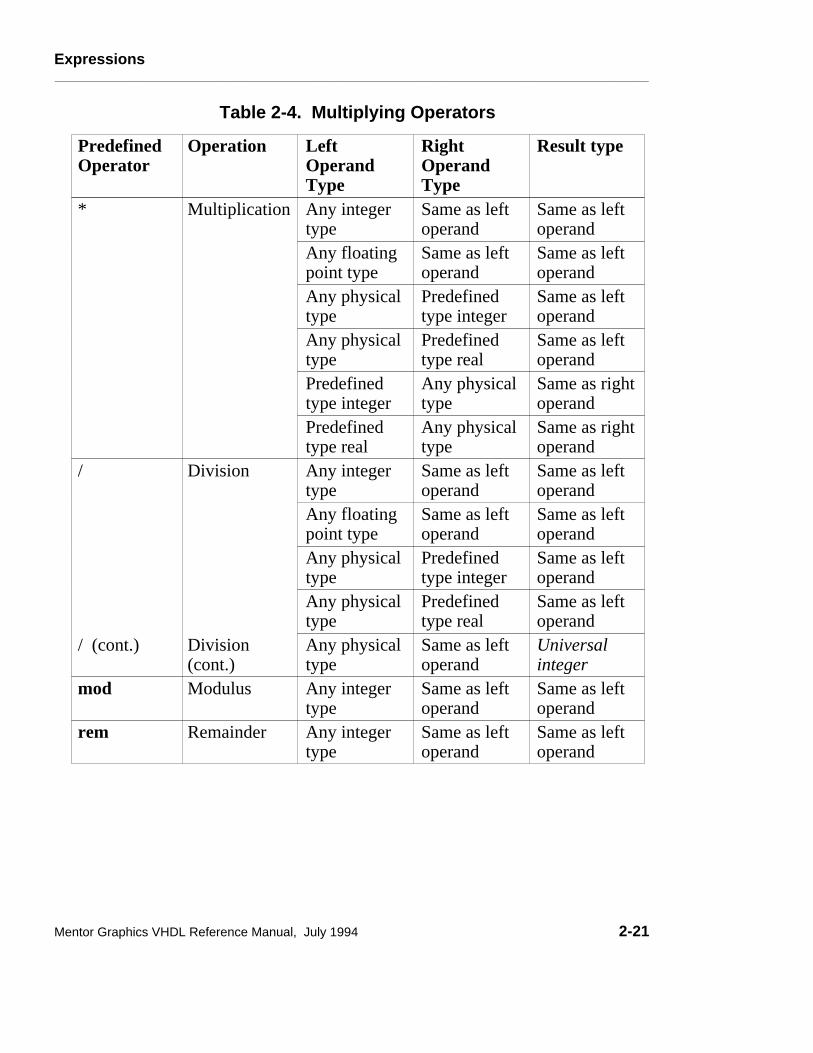
Expressions________________________________________________________________________________________________________________________
Table 2-4. Multiplying Operators
PredefinedOperator
Operation LeftOperandType
RightOperandType
Result type
* Multiplication Any integertype
Same as leftoperand
Same as leftoperand
Any floatingpoint type
Same as leftoperand
Same as leftoperand
Any physicaltype
Predefinedtype integer
Same as leftoperand
Any physicaltype
Predefinedtype real
Same as leftoperand
Predefinedtype integer
Any physicaltype
Same as rightoperand
Predefinedtype real
Any physicaltype
Same as rightoperand
/ Division Any integertype
Same as leftoperand
Same as leftoperand
Any floatingpoint type
Same as leftoperand
Same as leftoperand
Any physicaltype
Predefinedtype integer
Same as leftoperand
Any physicaltype
Predefinedtype real
Same as leftoperand
/ (cont.) Division(cont.)
Any physicaltype
Same as leftoperand
Universalinteger
mod Modulus Any integertype
Same as leftoperand
Same as leftoperand
rem Remainder Any integertype
Same as leftoperand
Same as leftoperand
Mentor Graphics VHDL Reference Manual, July 1994 2-21

Expressions________________________________________________________________________________________________________________________
Sign
The predefined sign operators "+" and "-" have their conventional definition. Thepositive "+" represents the identity function, and the negative "-" represents thenegation function. For the predefined sign operators, the operand and result havethe same type. The predefined sign operators are also called unary operators (asare abs and not). The formal syntax is shown as follows:
sign ::= + | -
The precedence of the predefined sign operators places restrictions on where youcan use them. A signed operand cannot follow these operators:
● A multiplying operator (For information on multiplying operators, refer topage 2-20.)
● A miscellaneous operator (For information on miscellaneous operators, referto page 2-18.)
● An adding operator (For additional information, refer to "Adding Operators").
For example:
A * - B --Illegal exp., sign follows multiplying operator.B / + C --Illegal exp., sign follows multiplying operator.Z ** - B --Illegal exp., sign follows miscellaneous operator.A +- B --Illegal exp., sign follows an adding operator.
If you use parentheses, the previous examples can be written as legal expressions.For example:
A * (- B) -- legal expressionB / (+ C) -- legal expressionZ ** (- B) -- legal expressionA + (-B) -- legal expression
2-22 Mentor Graphics VHDL Reference Manual, July 1994

Expressions________________________________________________________________________________________________________________________
Adding Operators
The adding operators are as follows:
adding_operator ::= - | & | +
The predefined adding operators "+" and "-" have their conventional definition.The concatenation operator (&) defines the connection of one-dimensional arraysand elements.
Table 2-5 lists the adding operators, their operations, and their operand and resulttypes.
Table 2-5. Adding Operators
PredefinedOperator
Operation LeftOperandType
RightOperandType
Result Type
+ Addition Any numerictype
Same as leftoperand
Same as leftoperand
- Subtraction Any numerictype
Same as leftoperand
Same as leftoperand
& Concatenation Anysingle-dim.array type
Same as left-operand arraytype
Same as leftoperand arraytype
Anysingle-dim.array type
Same aselement typeof leftoperand
Same as left-operand arraytype
Same aselement typeof rightoperand
Anysingle-dim.array type
Same asright-operandarray type
Any elementtype
The same asleft-operandelement type
An array ofelement type
Mentor Graphics VHDL Reference Manual, July 1994 2-23

Expressions________________________________________________________________________________________________________________________
For concatenation, the following three cases apply:
1. Both operands are one-dimensional arrays.
2. Only one operand is a one-dimensional array.
3. Both operands are of the array-element type.
These cases are described in the following paragraphs.
1. Following is an example of concatenation in which the operands are bothone-dimensional arrays:
PROCESS (sens_sig1)TYPE ref_array IS ARRAY (positive RANGE <>) OF integer;VARIABLE vector : ref_array (5 TO 9); --size is 5VARIABLE null_array: ref_array (5 TO 1); --typing error (TO)VARIABLE one_d : ref_array (6 DOWNTO 3); --size is 4 VARIABLE new_array : ref_array (9 DOWNTO 1); --size is 9
BEGINnew_array := vector & one_d; --Concatenate arrays, size is 9
END PROCESS;
The concatenation operation and the value of new_array from the precedingsens_sig1 process example is equivalent to the following:
�����������������������������������������������������������������������������������������������������������������������������������������������������������������������������������������������������������������������������������������������������������������������������������������������������������������������������������������������������������������������������������������������������������������������������������������������������������������������������������������������������������������������������������������������������������������������������������������������������������������������������������������������
������������������������������������������������������������������������������������������������������������������������������������������������������������������������������������������������������������������������������������������������������������������������������������������������������������������������������������������������������������������������������������������������������������������������������������������������������������������������������������������������������������������������������������������
vector
5 6 7 8 9 6 5 4 3
& one_d
5 6 7 8 9 10 11 12 13
resultant array from concatenation
������������������������������������������������������������������������������������������������������������������������������������������������������������������������������������������������������������������������������������������������������������������������������������������������������������������������������������������������������������������������������������������������������������������������������������������������������������������������������������������������������������������������������������������������������
9 8 7 6 5 4 3 2 1
new_array
The array created by the concatenation of two one-dimensional arrays has therange and direction of the left operand. In the sens_sig1 process, the leftoperand vector has an ascending range (5 TO 9). Therefore, the resultantarray also has an ascending range. The target variable new_array has the range
2-24 Mentor Graphics VHDL Reference Manual, July 1994

Expressions________________________________________________________________________________________________________________________
and direction specified in its own declaration, not that of the array created fromthe concatenation of the other two variables.
The left bound of the resulting array is the left bound of the left operand. If theleft operand is a null array*, the resulting concatenated array uses the range anddirection of the right operand. In the previous sens_sig1 process, the resultingconcatenated array has the left bound of 5 as determined by the left bound of theleft operand vector.
The size of the resulting array matches the total size of the combined right andleft operand array sizes. The elements of the resulting array consist of theelements of the left operand followed by the elements of the right operand.
2. Following is an example of concatenation in which only one operand is aone-dimensional array:PROCESS (sens_sig2)TYPE ref_array IS ARRAY (positive RANGE <>) OF integer;-- VARIABLE vector : ref_array (5 TO 9); -- size is 5VARIABLE next_array : ref_array (6 DOWNTO 1); -- size is 6
BEGINnext_array := vector & 3; --Concatenate "vector" with "3",
END PROCESS;
The concatenation operation and the value of next_array from the precedingsens_sig2 process is equivalent to the following:
vector &������������������������������������������������������������������������������������������������������������������������������������������
3 3
�����������������������������������������������������������������������������������������������������������������������������������������������������������������
3 resultant array from concatenation
5 6 7 8 9
5 6 7 8 9 10
6 5 4 3 2 1
next_array������������������������������������������������������������������������������������������������������������������������������������������
3
___________________*One way to encounter a null array like null_array is if the range isreversed, in this case typing TO instead of DOWNTO in the null_array variabledeclaration in the sens_sig1 process.
Mentor Graphics VHDL Reference Manual, July 1994 2-25

Expressions________________________________________________________________________________________________________________________
The resultant array created by the concatenation of a one-dimensional array withan array element has the range and direction of the index subtype of the leftoperand. In the sens_sig2 process, the resulting array uses an ascendingdirection as specified in the left operand (vector) declaration: VARIABLE vector : ref_array (5 TO 9);
The left bound of the resulting array is the left bound of the index subtype of theleft operand. In the sens_sig2 process, the left bound of the index subtype ofthe left operand vector is 5. The elements of the resulting array consist of theelements of the left operand followed by the elements of the right operand.
Had the concatenation in the sens_sig2 process placed the single element as theleft operand as shown below, the same rules would apply.
next_array := 3 & vector; --Concatenate "3" with "vector"
The single element "3" is viewed as an implied one-dimensional array with oneelement. The resultant array created by the concatenation of an array elementwith a one-dimensional array has the range and direction of the index subtype ofthe left operand. In this case, the resultant array from the concatenation startswith an index of 1 and has a range of 1 to 6. The following paragraphs include adescription of how a single element is treated as an implied array.
3. Following is an example of concatenation in which both operands are of thesame type as an array element type:
PROCESS (sens_sig3)TYPE ref_array IS ARRAY (positive RANGE <>) OF integer; VARIABLE x, z : integer;VARIABLE element_array : ref_array (6 TO 7);
BEGINx := 3; z := 5;element_array := x & z; --Concatenate to form 2-elem. array
END PROCESS;
The concatenation operation and the value of element_array from thepreceding sens_sig3 process is equivalent to the following:
2-26 Mentor Graphics VHDL Reference Manual, July 1994

Expressions________________________________________________________________________________________________________________________
&������������������������������������������������������������������������������������������������������������������������������������������1 TO 1
51 TO 1
3
3
1 2
�����������������������������������������������������������������������������������������������������������������������������������������������������������������
5
resultant array from concatenation
3
6 7
element_array�����������������������������������������������������������������������������������������������������������������������������������������������������������������
5
When you concatenate two non-array objects, each non-array object is treated asa one-dimensional array containing one element. It is important that at least onearray type declaration is visible in the current scope and that this visible arraytype declaration contain an element type that matches the type of the elementsyou are concatenating. In the case of the sens_sig3 process, variables x and zare both of type integer, which is the same as the elements in arrays of typeref_array.
In the sens_sig3 process, there is only one visible array type declaration thathas an element type that matches the type of the variables being concatenated.This means that the left bound and range of each of the implied one-elementarrays are determined by the ref_array type declaration. Each element of theimplied array has a left bound of 1 (the left bound of the positive <> value set)and an ascending range as determined by the range of the positive subtypedeclaration (SUBTYPE positive IS integer RANGE 1 TO integer’high;).The range of the implied arrays for x and z are 1 to 1.
Had the following type declaration also been included in the sens_sig3 process,overloading rules would determine which array type declaration to use todetermine the left bound and range of the implied arrays for x and z.
TYPE ref_array2 IS ARRAY (natural <>) OF integer; --unconst.
Now that we have determined what the implied arrays for x and z look like, wecan determine the left bound and range of the array that results from theconcatenation of the two implied arrays for x and z. The resultant array from theconcatenation of the two implied arrays has the range and direction of the indexsubtype of the implied array of the left operand. In the sens_sig3 process, theleft bound of the index subtype of the implied array is 1 and the range is
Mentor Graphics VHDL Reference Manual, July 1994 2-27

Expressions________________________________________________________________________________________________________________________
ascending. The elements of the resulting array consist of the left operandelements followed by the right operand elements.
You can also concatenate items to form a bus. The following example shows theinitialization of a four-bit type called my_qsim_state_vector:
VARIABLE a_bus: my_qsim_state_vector(0 TO 3); --variable decl.
a_bus := ’0’ & ’1’ & ’Z’ & ’X’ ; -- Assign initial valuesa_bus := "01ZX"; -- (or do it this way)
In the preceding example, the four bits are concatenated to form a bus. There is anatural inclination to assign a bus without using the "&" operator, or by usingsingle quotes, creating an illegal condition, as follows:
a_bus := ’01ZX’ ; -- illegal condition
Shift OperatorsS The shift operators perform bit shifting and rotation on operands. This release
of System-1076 fully supports the six shift operators defined in the IEEE Std1076-1993, IEEE Standard VHDL Hardware Description Language Manual.The following BNF description shows the shift operators:
relational_operator ::= sll | srl | sla | sra | rol | ror
Relational Operators
The relational operators check for equality, inequality, and the ordering ofoperands. The following BNF description shows the relational operators:
relational_operator ::= = | /= | < | <= | > | >=
Table 2-6 shows the standard VHDL relational operators, their operations, andtheir operand and result types. When you are using the standard VHDL operators(not using an overloaded version of one of these operators), the operands you usemust be of the same type, and the result type is always boolean.
2-28 Mentor Graphics VHDL Reference Manual, July 1994

Expressions________________________________________________________________________________________________________________________
Table 2-6. VHDL Relational Operators
Operator Operation Operand Type Result Type
= Equality Any type except file types Boolean
/= Inequality Any type except file types Boolean
< Ordering Any scalar or discretearray type
Boolean
<= Ordering Any scalar or discretearray type
Boolean
> Ordering Any scalar or discretearray type
Boolean
>= Ordering Any scalar or discretearray type
Boolean
Predefined Equality and Inequality Operators
As Table 2-6 shows, the equality and inequality operators are predefined for alltypes, except file types.
The equality operator "=" returns a value of TRUE if the left and right operandsare equal. Otherwise, a value of FALSE is returned. The inequality operator"/=" returns a value of FALSE if the left and right operands are equal.Otherwise, a value of TRUE is returned.
When you use two scalar values of the same type as operands, they are equal onlyif their values are the same. When you use two composite values of the sametype as operands, they are equal only if the following conditions exist:
● Each element of the left operand has a matching element in the right operand.(The left operand is no larger than the right operand.)
● Each element of the right operand has a matching element in the left operand.(The right operand is no larger than the left operand.)
● The matching elements in the left and right operands are equal.
Mentor Graphics VHDL Reference Manual, July 1994 2-29

Expressions________________________________________________________________________________________________________________________
Using the preceding conditions, two null arrays of the same type are alwaysconsidered equal.
When two one-dimensional arrays are compared, matching elements aredetermined by matching index values. Index values match if the left boundelement values of the index ranges match. If the left bound element valuesmatch, the next element values to the right are compared. This process continuesuntil the right bound of one of the arrays is reached.
Predefined Ordering Operators
As Table 2-6 shows, the ordering operators are predefined for any scalar ordiscrete array type. A discrete array type is a one-dimensional array that containselements that are of enumeration or integer types. Each ordering operator returnsa value of TRUE if the specified relation is satisfied. Otherwise, a value ofFALSE is returned.
Scalar type ordering operations are defined by the left and right operand relativevalues. For discrete array types, the relational operator "less than" (<) means thatthe left operand is less than the right operand if the following conditions aresatisfied:
● The left operand is a null array and the right operand is not a null array.
● The left and right operands are not null arrays. If they are not null arrays, oneof the following conditions must be met:
❍ The left-most element of the left operand is less than the left-most elementof the right operand.
❍ The left-most element of the left operand is equal to the left-most elementof the right operand, and the tail of the left operand is less than the tail ofthe right operand.
The tail of an operand is the remaining elements to the right of theleft-most element. The tail can be null.
The relational operator "less than or equal to" (<=), for discrete array types is trueif either "<" or "=" is true for the left and right operands you specify.
2-30 Mentor Graphics VHDL Reference Manual, July 1994

Expressions________________________________________________________________________________________________________________________
Using the definition of equality and less than, the remaining relational operatorscan be defined as follows:
● "Less than" is the complement to "greater than or equal to".
● "Greater than" is the complement to "less than or equal to".
Logical Operators
The logical operators are predefined for the types bit and boolean andone-dimensional arrays of type bit or boolean. The logical operators have theirconventional definitions (0 is false and 1 is true). The following syntaxdescription shows the logical operators:
logical_operator ::= and | or | nand | nor | xor | xnor
If the operands are arrays and the logical operator is a logical operator other thannot, then the following information applies to the expression:
● The operands must be the same length.
● The operation is accomplished by computing the result of applying theoperator to matching elements of the the arrays.
● The result is an array of the same subtype as the left operand with the sameindex range.
If the operand is an array and the logical operator is not, the not operation isperformed on each array element and the result is an array of the same subtype asthe operand with the same index range.
There are other expressions that are special cases that do not fall into theexpression categories in the previous discussion about expressions. Theseexpressions are identified as follows and are further described in the followingsubsections:
● Static expressions
● Universal expressions
Mentor Graphics VHDL Reference Manual, July 1994 2-31

Expressions________________________________________________________________________________________________________________________
Static ExpressionsStatic expressions fall into two categories:
● Locally static
● Globally static
A locally static expression is an expression that can be completely evaluatedwhen the design unit in which it appears is evaluated. The values for locallystatic expressions depend only on those declarations that are local to the designunit or on any packages used by the design unit.
A locally static expression must use operators that are predefined and all theoperands and results of the expression must be scalar types. Therefore, if you usean overloaded operator in an expression, it is not a locally static expression.Every operand in the expression must be a locally static operand. A locally staticoperand is one of the items listed in Table 2-7.
A globally static expression is an expression that can be evaluated when thedesign hierarchy where the expression appears is elaborated. The values forglobally static expressions may depend upon declarations that appear in otherdesign units. The values for globally static expressions are determined when thedesign unit is elaborated.
A globally static expression must use operators that are predefined. Therefore, ifyou use an overloaded operator in an expression, it is not a globally staticexpression. Every operand in the expression must be a globally static operand.A globally static operand is one of the items listed in Table 2-8.
2-32 Mentor Graphics VHDL Reference Manual, July 1994

Expressions________________________________________________________________________________________________________________________
Table 2-7. Local Static Operands
Locally StaticOperand
Rules For the Locally Static Operand
Constant No deferred constants are allowed. Constant must bedeclared with a locally static subtype and initializedusing a locally static expression.
Predefinedattribute
Must be an attribute of a locally static subtype that is avalue or a function with actual parameters that arelocally static.
Function call The function name must designate a predefinedoperator. Actual parameters must be locally static.
Literal Any scalar literal type. Qualifiedexpression
The type mark must designate a locally static subtype.The operand must be a locally static expression.
Locally staticexpression
May be enclosed by parentheses.
Mentor Graphics VHDL Reference Manual, July 1994 2-33

Expressions________________________________________________________________________________________________________________________
In this manual, several items are defined as locally static :
● Locally static range: a range with bounds that are locally static expressions.
● Locally static range constraint: a range constraint with a range that is locallystatic.
● Locally static scalar subtype: a scalar type (or subtype) or base type that isformed by restricting a locally static subtype by imposing a locally staticrange.
● Locally static discrete range: a locally static subtype or locally static range.
● Locally static index constraint: an index constraint in which each indexsubtype of the corresponding array type is locally static. Each discrete rangeis locally static.
● Locally static array subtype: a constrained array subtype that is formed byrestricting an unconstrained array type using a locally static index constraint.
Ranges are discussed on page 5-5, scalar types are discussed on page 5-4, andarrays are discussed on page 5-22.
2-34 Mentor Graphics VHDL Reference Manual, July 1994

Expressions________________________________________________________________________________________________________________________
Table 2-8. Global Static Operands
Globally StaticOperand
Rules For the Globally Static Operand
Locally staticoperand
Any locally static operand is considered a globallystatic operand.
Constant Deferred and generic constants are allowed. Constantsmust be declared with globally static subtype.
Predefinedattribute
Must be an attribute of a globally static subtype that isa value, range, or a function with actual parameters thatare globally static.
Function call The function name must designate a predefinedoperator. Actual parameters must be globally static.
Qualifiedexpression
The type mark must designate a globally static subtype.The operand must be a globally static expression.
Globally staticexpression
May be enclosed by parentheses.
Aggregate Must have a globally static subtype, and its elementassociations can contain only globally staticexpressions.
In this manual, several items are defined as being globally static:
● Globally static range: a range with bounds that are globally staticexpressions.
● Globally static range constraint: a range constraint with a range that isglobally static.
● Globally static scalar subtype: a scalar type (or subtype) or base type that isformed by restricting a globally static subtype by imposing a globally staticrange.
● Globally static discrete range: a globally static subtype or globally staticrange.
● Globally static index constraint: an index constraint in which each indexsubtype of the corresponding array type is globally static. Each discrete rangeis globally static.
Mentor Graphics VHDL Reference Manual, July 1994 2-35

Expressions________________________________________________________________________________________________________________________
● Globally static array subtype: a constrained array subtype that is formed byrestricting an unconstrained array type using a globally static index constraint.
Ranges are discussed on page 5-5, scalar types are discussed on page 5-4, andarrays are discussed on page 5-22.
Universal ExpressionsA universal expression is an expression that has a result type of universal_integeror universal_real. For a discussion about universal_integer and universal_real,refer to pages 5-9 and 5-12, respectively.
For any integer-type predefined operation, there is an equivalentuniversal_integer predefined operation. Likewise, for any floating-point typepredefined operation, there is an equivalent universal_real predefined operation.Table 2-9 lists the additional operand and result types for the multiplication anddivision predefined operators.
Table 2-9. Universal Expression Operators
Operator Operation LeftOperandType
RightOperandType
Result Type
* Multiplication universalreal
universalinteger
universalreal
universalinteger
universalreal
universalreal
/ Division universalreal
universalinteger
universalreal
2-36 Mentor Graphics VHDL Reference Manual, July 1994

Naming, Scope, and Visibility________________________________________________________________________________________________________________________
Section 3Naming, Scope, and Visibility
S This section discusses two topics: the concept of names and the concept ofscope and visibility. You must identify every design item you declare with someform of name. The system requires a design item to be named before the systemcan manipulate the design item. Each design you create may have hundreds ofnames within it. This collection of names forms a name space. There can onlybe one declaration of a given name per name space, and the collection of namespaces forms the complete name space.
To make the task of managing the complete name space controllable, VHDLprovides scope and visibility rules. The scope of a design item is the region oftext in which the declaration of the item has effect. Visibility rules define wherethe name from a declaration can be seen. The following ordered list shows thetopics described in this section:
Naming 3-3Simple Names 3-4Selected Names 3-4Indexed Names 3-8Slice Names 3-9Attribute Names 3-10
Scope and Visibility 3-12Declarative Region 3-12Scope 3-13Visibility 3-16Overload Resolution 3-24
Mentor Graphics VHDL Reference Manual, July 1994 3-1

Naming, Scope, and Visibility________________________________________________________________________________________________________________________
Naming Scope & Visibility
Naming, Scope, and Visibility
Lexical Elements
Expressions
Simple NamesSelected NamesIndexed Names
Slice NamesAttribute Names
Operator Symbols
������������������������������������������������������������������������������������������������������������������������������
SignalsTypes
Configurations
Design Entities
ComponentsAttributes
Packages
Design Units
Subprograms
Declarations
Statements
Figure 3-1. Naming, Scope, and Visibility
3-2 Mentor Graphics VHDL Reference Manual, July 1994

Naming, Scope, and Visibility________________________________________________________________________________________________________________________
NamingYour VHDL code must be able to refer to a declared item to act upon it.Therefore, each declared item must have a name. Names formally designate oneof the following:
● Explicitly or implicitly declared items
● Subelements of composite objects
● Attributes
● Objects denoted by access values
Here are some examples that show the use of names:
VARIABLE vcc : integer := 5; -- "vcc" is a simple nametest’base’left -- "test’base’left" is an attribute name
To refer to a design item, you use the name assigned to that design item.Declared items such as design entities, packages, and procedures are named usingthe simple_name construct. In some cases, you may want to reference a certainportion of an item, such as element of an array or record. In those cases, youmight use an indexed name or selected name. In all, there are six forms of namesyou can use, as the following BNF description illustrates.
name ::= simple_name | operator_symbol | selected_name | indexed_name | slice_name | attribute_name
The following subsections show you how to use simple names, selected names,indexed names, slice names and attribute names. The operator symbol is a namefor an operator that you can overload and use to manipulate objects. This topic isdiscussed in the subprogram declaration description on page 7-6.
Mentor Graphics VHDL Reference Manual, July 1994 3-3

Naming, Scope, and Visibility________________________________________________________________________________________________________________________
Simple Names
When you declare an item using an identifier, you use a simple name. When thesimple name is evaluated, the item to which it refers is determined. Every itemyou explicitly declare has a simple name, and some items declared implicitlyhave a simple name (such as labels and loop indexes). The following BNFsyntax description shows the related syntax for a simple name:
simple_name ::= identifier
identifier ::= letter {[_] letter | digit}
All declarations require simple names. The following are some valid simplename examples within a line of code:
ARCHITECTURE behave OF shifter IS --"behave" is the simple name (identifier) in the first line -- of the architecture_body construct.
ENTITY counter IS --"counter" is the simple name (identifier) in the first line-- of the entity_declaration construct.
FUNCTION chk_parity--"chk_parity" is the simple name (identifier) in the first -- line of the subprogram_specification construct.
Selected Names
Selected names designate elements of record types, objects pointed to by accessvalues, and items declared within another item, design library, or package. Youuse selected names in use clauses, which are discussed on page 3-22. You canuse a selected name to designate all the items declared in a library or package byusing the reserved word all. You can also use selected names to resolveoverloading conflicts.
The use of selected names to access individual elements of records is discussedunder "record_type_definition," beginning on page 5-29. The use of selectednames for objects pointed to by access values is discussed under "Allocators,"beginning on page 2-13.
3-4 Mentor Graphics VHDL Reference Manual, July 1994

Naming, Scope, and Visibility________________________________________________________________________________________________________________________
The following BNF descriptions show the syntax for a selected name:
selected_name ::= prefix . suffix
suffix ::= simple_name | character_literal | operator_symbol | all
The following examples show the use of selected names:
USE standard.time; -- The item "time" in package standardUSE standard.ALL; -- All the items in package standard
USE prim_lib.gates.and2; --AND from "gates" in "prim_lib"
USE gen_lib.or2, gen_lib.exor; --OR and XOR gates from gen_lib
The selected, indexed, slice, and attribute names require a prefix. As thefollowing BNF description shows, the prefix can be either a name or a functioncall.
prefix ::= name | function_call
When a name prefix is a function call, the suffix designates an attribute, element,or slice of the function call result. For information on function calls, refer topage 7-15.
When a name is evaluated, the item designated by the name is determined. If thename has a prefix, the name or function call designated by the prefix is evaluated.
Throughout this manual, there are several rules that involve a concept called thelongest static prefix. The longest static prefix is equivalent to the static signalname you use. If you do not use a static signal name, the longest static prefix is
Mentor Graphics VHDL Reference Manual, July 1994 3-5

Naming, Scope, and Visibility________________________________________________________________________________________________________________________
the static part of the name you use. For example:
sname(5)(7)
Static Name
���������������������������������������������������������������������������������������������������������������������������������������������������������������������������������������������������������������������������������������������������
sname(5)(7)
Longest Static Prefix
In the preceding example, the signal name contains the static expressions(5)(7), which designate the name as a static signal name. Therefore, the entiresignal name is the longest static prefix. Another example follows:
sname(5)(j)
Static Name
������������������������������������������������������������������������������������������������������������������������������������������������������������������������������������������������������������������������������������������������������������������������������
sname(5)
Longest Static Prefix
Non-Static Expression
In the preceding example, j is a variable. Therefore, the expression (j) isnon-static. The longest static prefix is the static part sname(5). Anotherexample follows:
sname(x)(j)
Static Name
���������������������������������������������������������������������������������������������������������������������������������������������������������������������������������������������������������������������������������������������������
sname
Longest Static Prefix
Non-Static Expression
In the preceding example, j and x are variables. Therefore, the expression(x)(j) is non-static. The longest static prefix is the static part sname.
3-6 Mentor Graphics VHDL Reference Manual, July 1994
Naming, Scope, and Visibility________________________________________________________________________________________________________________________
Another form of the selected name is the expanded name. The expanded namedesignates one of the following:
● Primary unit in a design library. In this case, the prefix designates the library,and the suffix is a primary unit simple name, which you declare within thelibrary designated by the prefix. For example: USE design_lib.and_gate ;
● Item declared in a package. In this case, the prefix designates the package,and the suffix is not the reserved word all. The simple name character literalor operator symbol declaration you use as the suffix must be declaredimmediately within the package designated in the prefix.
● All items declared in a package. In this case, the prefix designates thepackage, and the suffix is all.
● Item declared immediately within a named construct. In this case, the prefixdesignates one of the following:
❍ Entity
❍ Architecture
❍ Subprogram
❍ Block statement
❍ Process statement
❍ Loop statement
The suffix must not be the reserved word all. The simple name characterliteral or operator symbol declaration you use as the suffix must be declaredimmediately within the construct designated in the prefix.
An expanded name used to designate an item declared immediately within anamed construct is allowed only within the construct named in the prefix.
The suffix is the item in a design library or package that you wish to select. Thisselection can be a single item, several items, or all the items that the designlibrary or package contains. To select all the items, you use the reserved wordall.
Mentor Graphics VHDL Reference Manual, July 1994 3-7

Naming, Scope, and Visibility________________________________________________________________________________________________________________________
Indexed Names
You use an indexed name to designate an element of an array. The followingBNF description shows the syntax for an indexed name.
indexed_name ::= prefix ( expression { , expression } )
The prefix you use must be valid for array types. For information on array types,refer to page 5-22.
You use one or more expressions to designate the index value for an arrayelement. For example:
PROCESS TYPE one_array IS ARRAY (positive RANGE <>) OF integer; TYPE two_array IS ARRAY (positive RANGE <>, positive RANGE <>) OF integer; VARIABLE my_matrix : one_array (1 TO 5); VARIABLE d_matrix : two_array (1 TO 10, 1 TO 10); VARIABLE y, w : integer;BEGIN y := my_matrix(3); --The element in the position of the --array my_matrix designated by the index value 3
W := d_matrix(2,3); --The element in the position of the --two-dimensional array 2d_matrix --designated by the index 2,3 WAIT FOR 10 ns;END PROCESS;
You must use a corresponding number of expressions for the dimension of thearray. In the preceding example, if you designate an element of d_matrix, youneed two expressions (for example (2,3)). If you use one expression (forexample (3)), an error occurs, because another dimension is needed to locate thearray element.
3-8 Mentor Graphics VHDL Reference Manual, July 1994

Naming, Scope, and Visibility________________________________________________________________________________________________________________________
Slice Names
A slice name designates a one-dimensional array that is created from aconsecutive portion of another one-dimensional array. A slice of a design itemequates to a new design item of the same type. The following diagram shows thesyntax for a slice name:
slice_name ::= prefix ( discrete_range )
The following example shows the concept of using a slice name:
PROCESS (sens_signal)TYPE ref_array IS ARRAY (positive RANGE <>) OF integer; VARIABLE array_a : ref_array (1 TO 12); -- declare "array_a"VARIABLE array_b : ref_array (1 TO 4); -- declare "array_b"
BEGINFOR i IN 1 TO 12 LOOP --Load array with values array_a (i) := i + 10 ; --11 through 22
END LOOP;array_b := array_a (6 TO 9); -- slice of "array_a"
END PROCESS;
Figure 3-2 illustrates the preceding example.
������������������������������������������������������������������������������������������������������������������������������������������������������������������������������������������������������������������������������������������������������������������������������������������������������������������������������������������������������������������������������������������������������������������������������������������������������������������������������������������������������������������������������������������������������������������������������������������������������������������������������������������������������������������������������������������������������������������������������������������������������������������������������������������������������������������������������������������������������������������������������������
������������������������������������������������������������������������������������������������������������������������������������������������������������������������������������������������������������������������������������������������������������������������������������������������������������������������������������������������������������������������������������������������������������������������������������������������������������������������������������������������������������������������������������������������������������������������������������������������������������������������������������������������������������������������������������������������������������������������������������������������������������������������������������������������������������������������������������������������������������������������������������
11 12 13 14 15 16 17 18 19 20 21 22
16 17 18 19
array_a
array_b
1 2 3 4 5 6 7 8 9 10 11 12
1 2 3 4
Figure 3-2. Slice Name Concept
Mentor Graphics VHDL Reference Manual, July 1994 3-9

Naming, Scope, and Visibility________________________________________________________________________________________________________________________
The prefix you use must be valid for one-dimensional array types. Forinformation on array types, refer to page 5-22.
You specify the array bounds of the slice by using a discrete range. The discreterange you specify must be of the same type as the index of the array you areslicing. If you specify a null discrete range or a range direction opposite to theobject designated by the slice name prefix, the slice is a null slice.
When a slice name is evaluated, an error occurs if you specify a discrete rangewith bounds that do not belong to the index range specified in the prefix array.No error occurs if a null slice is specified, because the null slice bounds do nothave to be a subtype of the index range specified by the prefix array.
Some slice name examples follow:
-- Begin by declaring a constant, signal, and variable:--TYPE this_array IS ARRAY (natural RANGE <>) OF integer; CONSTANT result: this_array (0 TO 100) := (OTHERS => 0);SIGNAL traffic_lights: bit_vector (0 TO 7);--Declare a signalVARIABLE test: this_array (10 DOWNTO 1); --Declare a variable
-- Slices of the constant, signal, and variable:--result (25 TO 50) --Slice of the array resulttraffic_lights (5 TO 4) --Null slice because wrong directiontest (5 DOWNTO 1) --Slice of the array testresult (0 DOWNTO 100) --Null slice, because range of slice
--is opposite of the range declared for the array result. --(Also, a range of 0 downto 100 is null by itself.)
Attribute Names
An attribute name consists of a prefix and an attribute designator. For predefinedattributes, the prefix denotes an array, block, signal, or type. The prefix for auser-defined attribute may denote an entity declaration, an architecture body, aconfiguration, a procedure, a function, a package, a type, a subtype, a constant, asignal, a variable, a component, or a label.
The attribute designator is the simple name for the predefined attribute. Theattribute returns certain information about the item named in the prefix, such aslength of an array or whether a signal is active. The complete discussion ofattributes is covered in Section 10. The following diagram shows the related
3-10 Mentor Graphics VHDL Reference Manual, July 1994

Naming, Scope, and Visibility________________________________________________________________________________________________________________________
syntax for an attribute name.
attribute_name ::= prefix ’ attribute_designator [ ( expression ) ]
attribute_designator ::= attribute_simple_name
The expression in the attribute name may be required or may be optional,depending on the particular attribute definition.
The following examples show the declaration of two types and the use ofattribute names to determine information on these types. These are source-codefragments taken out of context.
TYPE color IS(red, white, blue, orange, purple); --type decl.TYPE vector IS ARRAY (1 TO 10, 1 TO 15) OF integer;
color’val(2) --Returns the value of element in position 2 of --the type "color" which is blue (positions --start at zero)
vector’right(1) --returns right bound of the specified index -- "1" in the array "vector" which is 10
There are several terms used to describe to a certain subclass of names, as thefollowing list shows:
● Static name
● Static expression
● Static signal name
Indexed names have an expression as part of the language construct. If you use astatic expression, the name is a static name.
A static expression* is one whose value is determined either at compile time or atelaboration time. For example, when you use a signal that is declared in aprevious design unit, the signal value is not known in the current design unit.Therefore, using this signal name in an expression makes it a non-static
___________________*For more information on static expressions, refer to page 2-32.
Mentor Graphics VHDL Reference Manual, July 1994 3-11

Naming, Scope, and Visibility________________________________________________________________________________________________________________________
expression. For detailed information about the design unit, refer to Section 9.
If you use a static name to designate a signal, the name is considered a staticsignal name.
Scope and VisibilityS Scope and visibility are concepts that are closely related. The scope is the region of code text over which an item exists (declarative region). Within thescope, visibility refers to an item that has a unique name that you can reference.If an item is hidden, it is not visible without using a selected name. This topic isdiscussed on page 3-17.
Using the concepts of scope and visibility and by using the rules of overloading,you can control the name space. That is, you can control where names haveeffect without worrying about the global effects of manipulating a named item.This becomes a very important factor when your design contains hundreds ofnames. The following subsections describe in detail the following items:
● The declarative region
● The concept of scope and the scope rules
● The concept of visibility and the visibility rules
● Overloading concepts
Declarative Region
Scope and visibility are defined in terms of declarative regions. The declarativeregion is a part of the text of a description. The declarative region is formed bythe text of the following items:
● Component declaration (page 8-21)
● Entity declaration (combined with an architecture body) (page 8-4)
● Package declaration (combined with a package body if it exists) (page 9-13)
● Subprogram declaration (combined with a subprogram body) (page 7-6)
3-12 Mentor Graphics VHDL Reference Manual, July 1994

Naming, Scope, and Visibility________________________________________________________________________________________________________________________
● Block statement (page 6-12)
● Loop statement (page 6-36)
● Process statement (page 6-41)
Each declarative region in the preceding list is associated with a correspondingdeclaration or statement. The declaration is immediately within a declarativeregion if the corresponding region is the innermost region enclosing thedeclaration. This innermost region does not include the declarative region (if itexists) of the declaration. The following example shows a skeleton of a blockstatement and the declarative region:
test_block:BLOCK -- declarative regionTYPE test IS 1 TO 10;
BEGIN
-- concurrent statements
END BLOCK test_block;
Scope
Scope is the region of code over which a declared item has effect. For example,if you declare objects inside a block statement, the scope of the objects extendsfrom the point where you first name the objects to the end of the block statement.
Figure 3-3 shows an architecture body that contains a procedure within a process.Region A shows the scope of the subprogram specification (procedure); region Bshows the scope of the process statement; and region C shows the scope of thearchitecture body.
Mentor Graphics VHDL Reference Manual, July 1994 3-13

Naming, Scope, and Visibility________________________________________________________________________________________________________________________
ARCHITECTURE
SIGNAL
BEGIN
PROCESS
VARIABLE
END;
PROCEDURE
BEGIN
BEGIN
END PROCESS;
END;
.
.
.
.
.
A B C
Figure 3-3. Scope
Figure 3-4 shows that even though the architecture body can be stored andevaluated in a file separate from the entity declaration, an item declared in theentity declaration (such as signal1) is visible throughout region C. An itemdeclared in a package header is visible to the package header and the packagebody.
3-14 Mentor Graphics VHDL Reference Manual, July 1994

Naming, Scope, and Visibility________________________________________________________________________________________________________________________
ARCHITECTURE a1 OF en1 IS
SIGNAL2
BEGIN
PROCESS
VARIABLE
END a1;
PROCEDURE
BEGIN
BEGIN
END PROCESS;
END;
.
.
.
.
.
In File "arch1.hdl"
ENTITY en1 IS
SIGNAL1
END en1;
In File "entity1.hdl"
AB
C
Figure 3-4. Scope of Entity Plus Architecture
Scope Rules
The scope rules discussed in this subsection are valid for all declaration forms,implicit or explicit.
Immediate scope is the scope of a declaration that is directly within a declarativeregion. Table 3-1 lists the cases in which a declaration extends beyond itsimmediate scope.
Mentor Graphics VHDL Reference Manual, July 1994 3-15

Naming, Scope, and Visibility________________________________________________________________________________________________________________________
Table 3-1. Immediate Scope Exceptions
Declaration Occurring Within
Formal parameter Subprogram declaration *
Declaration Package declaration **
Local generic Component declaration
Local port Component declaration
Formal generic Entity declaration
Formal port Entity declaration
* This extension is also valid if a separate subprogram declaration is missing and the subprogram body is used as the declaration.
** The declaration must occur immediately within the package declaration.
The library unit scope and logical library name scope in a design library extendbeyond the immediate scope.
Visibility
Visibility refers to an item that has a unique name, thereby making it an item youcan refer to in a code description. An item may be hidden from other portions ofcode by the nesting of language constructs and by the use of homographs. Figure3-5 shows the variable declared within the procedure is visible only to thehighlighted area (or its scope).
An item declared in the entity declaration such as signal1 in Figure 3-4 can bevisible to the entire scope identified by region C unless it is hidden, as describedlater.
3-16 Mentor Graphics VHDL Reference Manual, July 1994

Naming, Scope, and Visibility________________________________________________________________________________________________________________________
����������������������������������������������������������������������������������������������������������������������������������������������������������������������������������������������������������������������������������������������������������������������������������������������������������������������������������������������������������������������������������������������������������������������������������������������������������������������������������������������������������������������������������������������������������������������������������������������������������������������������������������������������������������������������������������������������������������������������������������������������������������������������������������������������������������������������������������������������������������������������������������������������������������������������������������������������������������������������������������������������������������������������������������������������������������������������������������������������������������������������������������������������������������������������������������������������������������������������������������������������������������������������������������������������������������������������������������������������������������������������������������������������������������������������������������������������������������������������������������������������������������������������������������������������������������������������������������������������������������������������������������������������������������������������������������������������������������������������������������������������������������������������������������������������������������������������������������������������������������������������������������������������������������������������������������������������������������������������������������������������������������������������������������������������������������������������������������������������������������������������������������������������������������������������������������������������������������������������������������������
ARCHITECTURE
SIGNAL
BEGIN
PROCESS
VARIABLE
END;
PROCEDURE
BEGIN
BEGIN
END PROCESS;
END;
.
.
.
.
.
VARIABLE
Figure 3-5. Visibility
Visibility Rules
The visibility rules establish the meaning of an identifier. The possible meaningsof the occurrence of this identifier are determined during evaluation. Thefollowing list shows the two possible results of this determination:
● One possible meaning: the visibility rules alone find the declaration thatdefines the identifier meaning. If this declaration does not exist, the visibilityrules alone determine that the identifier is not legal.
● Multiple meanings: the visibility rules find multiple meanings for theidentifier. In other words, it is overloaded. Within the related context, onevisible declaration is used if the overloading rules have been met. Forinformation on overloading rules, refer to page 3-24.
An identifier can be made visible by two different means, as the following listshows:
Mentor Graphics VHDL Reference Manual, July 1994 3-17

Naming, Scope, and Visibility________________________________________________________________________________________________________________________
● Selection: if the item is hidden, it becomes visible only when you use aselected name. Selected names designate an item declared within anotheritem. For more information on selected names, refer to page 3-4.
● Directly visible: if the item is not hidden, it is directly visible. A directlyvisible declaration is also visible by selection.
Table 3-2 shows the places where a declaration is visible by selection.
Any declaration that occurs immediately within a declarative region of alanguage construct is visible by selection at the suffix of an expanded name. Theprefix of this expanded name must designate the language construct. For moreinformation on expanded names, refer to page 3-6.
A declaration is directly visible in a specific area of the immediate scope. Thisarea encompasses the area between the declaration and the end of the immediatescope, except for areas where the declaration is hidden. You can make adeclaration that occurs immediately within the visible part of a package directlyvisible outside the package by using the use clause. For more information on theuse clause, refer to page 3-22.
Two declarations are homographs of each other if they both use a commonidentifier and if overloading is allowed for at most one of the two declarations.There are two homograph cases: one declaration can be overloaded and the othercannot; or both declarations can be overloaded and they have the same parameterand result type profile. Only enumeration literals or subprogram declarations canbe overloaded.
Homographs declared within the same declarative region create an error. Withhomographs declared in different regions, the inner declaration hides thecorresponding outer declaration within the inner scope region. In this case, thehomograph declared in the outer region is not visible within the inner region.
Two formal parameter lists have the parameter type profile if they have the samenumber of parameters in the list and if the parameters at each position in the listhave the same base type. Two subprograms have the same parameter and resulttype profile if they both have the same parameter profile and if they arefunctions, the functions return a result with the same base type. In the case ofenumeration literals, no homograph exists if the base types are different. Forinformation on overloading, refer to page 3-24.
3-18 Mentor Graphics VHDL Reference Manual, July 1994

Naming, Scope, and Visibility________________________________________________________________________________________________________________________
Table 3-2. Visibility by Selection
Design Item Selected By
Primary unit in library Suffix in selected name (prefix designates thelibrary)
Declaration in packagedeclaration
Suffix in selected name (prefix designates thepackage)
Predefined attribute thatapplies to a given rangeof definition
Attribute designator (after ’) in attribute name.
Formal parameter decl.of specified subprogramdeclaration
Formal designator (before =>) in parameterassociation list.
Local generic decl. ofspecified componentdeclaration
Formal designator (before =>) in a namedgeneric association list of a correspondingcomponent instantiation statement; or actualdesignator (after =>) in generic association listof a corresponding binding indication
Local port decl. ofspecified componentdeclaration
Formal designator (before =>) in a named portassociation list of a corresponding componentinstantiation statement; or actual designator(after =>) in port association list of acorresponding binding indication
Formal generic decl. ofspecified entity decl.
Formal designator (before =>) in generic assoc.list of a corresponding binding indication
Formal port decl. ofspecified entity decl.
Formal designator (before =>) in port assoc. listof a corresponding binding indication
Element of a record Suffix in selected name (prefix denotes record)
Figure 3-6 shows an example of hidden declarations and homographs.
Mentor Graphics VHDL Reference Manual, July 1994 3-19

Naming, Scope, and Visibility________________________________________________________________________________________________________________________
������������������������������������������������������������������������������������������������������������������������������������������������������������������������������������������������������������������������������������������������������������������������������������������������������������������������������������������������������������������������������������������������������������������������������������������������������������������������������������������������������������������������������������������������������������������������������������������������������������������������������������������������������������������������������������������������������������������������������������������������������������������������������������������������������������������������������������������������������������������������������������������������������������������������������������������������������������������������������������������������������������������������������������������������������������������������������������������������������������������������������������������������������������������������������������������������������������������������������������������������������������������������������������������������������������������������������������������������������������������������������������������������������������������������������������������������������������������������������������������������������������������������������������������������������������������������������������������������������������������������������������������������������������������������������������������������������������������������������������������������������������������������������������������������������������������������������������������������������������������������������������������������������������������������������������������������������������������������������������������������������������������������������������������������������������������������������������������������������������������������������������������������������������������������������������������������������������������������������������������������������������������������������������������������������������������������������������������������������������������������������������������������������������������������������������������������������������������������������������������������������������������������������������������������������������������������������������������������������������������������������������������������������������������������������������������������������������������������������������������������������������������������������������������������������������������������������������������������������������������������������������������������������������������������������������������������������������������������������������������������������������������������������������������������������������������������������������������������������������������������������������������������������������������������������������������������������������������������������������������������������������������������������������������������������������������������������������������������������������������������������������������������������������������������������������������������������������������������������������������������������������������������������������������������������������������������������������������������������������������������������������������������������������������������������������������������������������������������������������������������������������������������������������������������������������������������������������������������������������������������������������������������������������������������������������������������������������������������������������������������������������������������������������������������������������������������������������������������������������������������������������������������������������������������������������������������������������������������������������������������������������������������������������������������������������������������������������������������������������������������������������������������������������������������������������������������������������������������������������������������������������������������������������������������������������������������������������������������������������������������������������������������������������������������������������������������������������������������������������������������������������������������������������������������������������������������������������������������������������������������������������������������������������������������������������������������������������������������������������������������������������������������������������������������������������������������������������������������������������������������������������������������������������������������������������������������������������������������������������������������������������������������������������������������������������������������������������������������������������������������������������������������������������������������������������������������������������������������������������������������������������������������������������������������������������������������������������������������������������������������������������������������������������������������������������������������������������������������������������������������������������������������������������������������������������������������������������������������������������������������������������������������������������������������������������������������������������������������������������������������������������������������������������������������������������������������������������������������������������������������������������������������������������������������������������������������������������������������������������������������������������������������������������������������������������������������������������������������������������������������������������������������������������������������������������������������������������������������������������������������������������������������������������������������������������������������������������������������������������������������������������������������������������������������������������������������������������������������������������������������������������������������������������������������������������������������������������������������������������������������������������������������������������������������������������������������������������������������������������������������������������������������������������������������������������������������������������������������������������������������������������������������������������������������������������������������������������������������������������������������������������������������������������������������������������������������������������������������������������������������������������������������������������������������������������������������������������������������������������������������������������������������������������������������������������������������������������������������������������������������������������������������������������������������������������������������������������������������������������������������������������������������������������������������������������������������������������������������������������������������������������������������������������������������������������������������������������������������������������������������������������������������������������������������������������������������������������������������������������������������������������������������������������������������������������������������������������������������������������������������������������������������������������������������������������������������������������������������������������������������������������������������������������������������������������������������������������������������������������������������������������������������������������������������������������������������������������������������������������������������������������������������������������������������������������������������������������������������������������������������������������������������������������������������������������������������������������������������������������������������������������������������������������������������������������������������������������������������������������������������������������������������������������������������������������������������������������������������������������������������������������������������������������������������������������������������������������������������������������������������������������������������������������������������������������������������������������������������������������������������������������������������������������������������������������������������������������������������������������������������������������������������������������������������������������������������������������������������������������������������������������������������������������������������������������������������������������������������������������������������������������������������������������������������������������������������������������������������������������������������������������������������������������������������������������������������������������������������������������������������������������������������������������������������������������������������������������������������������������������������������������������������������������������������������������������������������������������������������������������������������������������������������������������������������������������������������������������������������������������������������������������������������������������������������������������������������������������������������������������������������������������������������������������������������������������������������������������������������������������������������������������������������������������������������������������������������������������������������������������������������������������������������������������������������������������������������������������������������������������������������������������������������������������������������������������������������������������������������������������������������������������������������������������������������������������������������������������������������������������������������������������������������������������������������������������������������������������������������������������������������������������������������������������������������������������������������������������������������������������������������������������������������������������������������������������������������������������������������������������������������������������������������������������������������������������������������������������������������������������������������������������������������������������������������������������������������������������������������������������������������������������������������������������������������������������������������������������������������������������������������������������������������������������������������������������������������������������������������������������������������������������������������������������������������������������������������������������������������������������������������������������������������������������������������������������������������������������������������������������������������������������������������������������������������������������������������������������������������������������������������������������������������������������������������������������������������������������������������������������������������������������������������������������������������������������������������������������������������������������������������������������������������������������������������������������������������������������������������������������������������������������������������������������������������������������������������������������������������������������������������������������������������������������������������������������������������������������������������������������������������������������������������������������������������������������������������������������������������������������������������������������������������������������������������������������������������������������������������������������������������������������������������������������������������������������������������������������������������������������������������������������������������������������������������������������������������������������������������������������������������������������������������������������������������������������������������������������������������������������������������������������������������������������������������������������������������������������������������������������������������������������������������������������������������������������������������������������������������������������������������������������������������������������������������������������������������������������������������������������������������������������������������������������������������������������������������������������������������������������������������������������������������������������������������������������������������������������������������������������������������������������������������������������������������������������������������������������������������������������������������������������������������������������������������������������������������������������������������������������������������������������������������������������������������������������������������������������������������������������������������������������������������������������������������������������������������������������������������������������������������������������������������������������������������������������������������������������������������������������������������������������������������������������������������������������������������������������������������������������������������������������������������������������������������������������������������������������������������������������������������������������������������������������������������������������������������������������������������������������������������������������������������������������������������������������������������������������������������������������������������������������������������������������������������������������������������������������������������������������������������������������������������������������������������������������������������������������������������������������������������������������������������������������������������������������������������������������������������������������������������������������������������������������������������������������������������������������������������������������������������������������������������������������������������������������������������������������������������������������������������������������������������������������������������������������������������������������������������������������������������������������������������������������������������������������������������������������������������������������������������������������������������������������������������������������������������������������������������������������������������������������������������������������������������������������������������������������������������������������������������������������������������������������������������������������������������������������������������������������������������������������������������������������������������������������������������������������������������������������������������������������������������������������������������������������������������������������������������������������������������������������������������������������������������������������������������������������������������������������������������������������������������������������������������������������������������������������������������������������������������������������������������������������������������������������������������������������������������������������������������������������������������������������������������������������������������������������������������������������������������������������������������������������������������������������������������������������������������������������������������������������������������������������������������������������������������������������������������������������������������������������������������������������������������������������������������������������������������������������������������������������������������������������������������������������������������������������������������������������������������������������������������������������������������������������������������������������������������������������������������������������������������������������������������������������������������������������������������������������������������������������������������������������������������������������������������������������������������������������������������������������������������������������������������������������������������������������������������������������������������������������������������������������������������������������������������������������������������������������������������������������������������������������������������������������������������������������������������������������������������������������������������������������������������������������������������������������������������������������������������������������������������������������������������������������������������������������������������������������������������������������������������������������������������������������������������������������������������������������������������������������������������������������������������������������������������������������������������������������������������������������������������������������������������������������������������������������
ARCHITECTURE
SIGNAL
BEGIN
PROCESS
VARIABLE x : boolean
END;
PROCEDURE
BEGIN
BEGIN
END PROCESS;
END;
.
.
.
.
.
VARIABLE x : boolean
A B C
Figure 3-6. Declaration Hiding and Homographs
In Figure 3-6 variable x is declared within the procedure in scope A and withinthe process in scope B. The variable x declared in the process is hidden withinscope A by the variable x declared in the procedure. The variable in scope A is ahomograph of the variable in scope B, because the variables have the sameidentifier.
Figure 3-7 shows an example of hidden declarations and overloading that resultsin no homograph.
3-20 Mentor Graphics VHDL Reference Manual, July 1994

Naming, Scope, and Visibility________________________________________________________________________________________________________________________
��������������������������������������������������������������������������������������������������������������������������������������������������������������������������������������������������������������������������������������������������������������������������������������������������������������������������������������������������������������������������������������������������������������������������������������������������������������������������������������������������������������������������������������������������������������������������������������������������������������������������������������������������������������������������������������������������������������������������������������������������������������������������������������������������������������������������������������������������������������������������������������������������������������������������������������������������������������������������������������������������������������������������������������������������������������������������������������������������������������������������������������������������������������������������������������������������������������������������������������������������������������������������������������������������������������������������������������������������������������������������������������������������������������������������������������������������������������������������������������������������������������������������������������������������������������������������������������������������������������������������������������������������������������������������������������������������������������������������������������������������������������������������������������������������������������������������������������������������������������������������������������������������������������������������������������������������������������������������������������������������������������������������������������������������������������������������������������������������������������������������������������������������������������������������������������������������������������������������������������������������������������������������������������������������������������������������������������������������������������������������������������������������������������������������������������������������������������������������������������������������������������������������������������������������������������������������������������������������������������������������������������������������������������������������������������������������������������������������������������������������������������������������������������������������������������������������������������������������������������������������������������������������������������������������������������������������������������������������������������������������������������������������������������������������������������������������������������������������������������������������������������������������������������������������������������������������������������������������������������������������������������������������������������������������������������������������������������������������������������������������������������������������������������������������������������������������������������������������������������������������������������������������������������������������������������������������������������������������������������������������������������������������������������������������������������������������������������������������������������������������������������������������������������������������������������������������������������������������������������������������������������������������������������������������������������������������������������������������������������������������������������������������������������������������������������������������������������������������������������������������������������������������������������������������������������������������������������������������������������������������������������������������������������������������������������������������������������������������������������������������������������������������������������������������������������������������������������������������������������������������������������������������������������������������������������������������������������������������������������������������������������������������������������������������������������������������������������������������������������������������������������������������������������������������������������������������������������������������������������������������������������������������������������������������������������������������������������������������������������������������������������������������������������������������������������������������������������������������������������������������������������������������������������������������������������������������������������������������������������������������������������������������������������������������������������������������������������������������������������������������������������������������������������������������������������������������������������������������������������������������������������������������������������������������������������������������������������������������������������������������������������������������������������������������������������������������������������������������������������������������������������������������������������������������������������������������������������������������������������������������������������������������������������������������������������������������������������������������������������������������������������������������������������������������������������������������������������������������������������������������������������������������������������������������������������������������������������������������������������������������������������������������������������������������������������������������������������������������������������������������������������������������������������������������������������������������������������������������������������������������������������������������������������������������������������������������������������������������������������������������������������������������������������������������������������������������������������������������������������������������������������������������������������������������������������������������������������������������������������������������������������������������������������������������������������������������������������������������������������������������������������������������������������������������������������������������������������������������������������������������������������������������������������������������������������������������������������������������������������������������������������������������������������������������������������������������������������������������������������������������������������������������������������������������������������������������������������������������������������������������������������������������������������������������������������������������������������������������������������������������������������������������������������������������������������������������������������������������������������������������������������������������������������������������������������������������������������������������������������������������������������������������������������������������������������������������������������������������������������������������������������������������������������������������������������������������������������������������������������������������������������������������������������������������������������������������������������������������������������������������������������������������������������������������������������������������������������������������������������������������������������������������������������������������������������������������������������������������������������������������������������������������������������������������������������������������������������������������������������������������������������������������������������������������������������������������������������������������������������������������������������������������������������������������������������������������������������������������������������������������������������������������������������������������������������������������������������������������������������������������������������������������������������������������������������������������������������������������������������������������������������������������������������������������������������������������������������������������������������������������������������������������������������������������������������������������������������������������������������������������������������������������������������������������������������������������������������������������������������������������������������������������������������������������������������������������������������������������������������������������������������������������������������������������������������������������������������������������������������������������������������������������������������������������������������������������������������������������������������������������������������������������������������������������������������������������������������������������������������������������������������������������������������������������������������������������������������������������������������������������������������������������������������������������������������������������������������������������������������������������������������������������������������������������������������������������������������������������������������������������������������������������������������������������������������������������������������������������������������������������������������������������������������������������������������������������������������������������������������������������������������������������������������������������������������������������������������������������������������������������������������������������������������������������������������������������������������������������������������������������������������������������������������������������������������������������������������������������������������������������������������������������������������������������������������������������������������������������������������������������������������������������������������������������������������������������������������������������������������������������������������������������������������������������������������������������������������������������������������������������������������������������������������������������������������������������������������������������������������������������������������������������������������������������������������������������������������������������������������������������������������������������������������������������������������������������������������������������������������������������������������������������������������������������������������������������������������������������������������������������������������������������������������������������������������������������������������������������������������������������������������������������������������������������������������������������������������������������������������������������������������������������������������������������������������������������������������������������������������������������������������������������������������������������������������������������������������������������������������������������������������������������������������������������������������������������������������������������������������������������������������������������������������������������������������������������������������������������������������������������������������������������������������������������������������������������������������������������������������������������������������������������������������������������������������������������������������������������������������������������������������������������������������������������������������������������������������������������������������������������������������������������������������������������������������������������������������������������������������������������������������������������������������������������������������������������������������������������������������������������������������������������������������������������������������������������������������������������������������������������������������������������������������������������������������������������������������������������������������������������������������������������������������������������������������������������������������������������������������������������������������������������������������������������������������������������������������������������������������������������������������������������������������������������������������������������������������������������������������������������������������������������������������������������������������������������������������������������������������������������������������������������������������������������������������������������������������������������������������������������������������������������������������������������������������������������������������������������������������������������������������������������������������������������������������������������������������������������������������������������������������������������������������������������������������������������������������������������������������������������������������������������������������������������������������������������������������������������������������������������������������������������������������������������������������������������������������������������������������������������������������������������������������������������������������������������������������������������������������������������������������������������������������������������������������������������������������������������������������������������������������������������������������������������������������������������������������������������������������������������������������������������������������������������������������������������������������������������������������������������������������������������������������������������������������������������������������������������������������������������������������������������������������������������������������������������������������������������������������������������������������������������������������������������������������������������������������������������������������������������������������������������������������������������������������������������������������������������������������������������������������������������������������������������������������������������������������������������������������������������������������������������������������������������������������������������������������������������������������������������������������������������������������������������������������������������������������������������������������������������������������������������������������������������������������������������������������������������������������������������������������������������������������������������������������������������������������������������������������������������������������������������������������������������������������������������������������������������������������������������������������������������������������������������������������������������������������������������������������������������������������������������������������������������������������������������������������������������������������������������������������������������������������������������������������������������������������������������������������������������������������������������������������������������������������������������������������������������������������������������������������������������������������������������������������������������������������������������������������������������������������������������������������������������������������������������������������������������������������������������������������������������������������������������������������������������������������������������������������������������������������������������������������������������������������������������������������������������������������������������������������������������������������������������������������������������������������������������������������������������������������������������������������������������������������������������������������������������������������������������������������������������������������������������������������������������������������������������������������������������������������������������������������������������������������������������������������������������������������������������������������������������������������������������������������������������������������������������������������������������������������������������������������������������������������������������������������������������������������������������������������������������������������������������������������������������������������������������������������������������������������������������������������������������������������������������������������������������������������������������������������������������������������������������������������������������������������������������������������������������������������������������������������������������������������������������������������������������������������������������������������������������������������������������������������������������������������������������������������������������������������������������������������������������������������������������������������������������������������������������������������������������������������������������������������������������������������������������������������������������������������������������������
ARCHITECTURE
FUNCTION x: RETURN integer;
BEGIN
PROCESS
END;
PROCEDURE x;
BEGIN
END PROCESS;
END;
.
.
.
.
BEGIN
.
VARIABLE x : boolean
A B C
Figure 3-7. No Homograph Instance
In Figure 3-7, function x is declared in scope C, and procedure x is declared inscope A. In this case, function x and procedure x are not homographs of eachother because the system can determine a difference between the two x values bythe context. Therefore, overloading is allowed for both of the values. If youreplace the function with a procedure, the two procedures are homographs ofeach other (if the procedures have the same parameter type), because the systemcannot determine a difference between the two identifiers.
Mentor Graphics VHDL Reference Manual, July 1994 3-21
Naming, Scope, and Visibility________________________________________________________________________________________________________________________
use_clauseThe use clause allows you to make directly visible a declaration in a package orlibrary that is visible by selection.
Construct Placementblock_declarative_item, context_item, entity_declarative_item,package_body_declarative_item, package_declarative_item,process_declarative_item, subprogram_declarative_item
Syntax
use_clause ::= use selected_name { , selected_name } ;
DescriptionYou can specify one or more selected names to identify declarations that youwant to become directly visible. (For more information on selected names, referto page 3-4.) You can also specify the use of all of the declarations by using thereserved word all. For example:
USE package_1.test_func1,package_1.test_func2 -- line 1 USE package_2.ALL -- line 2
Line 1 makes the functions test_func1 and test_func2, from package_1directly visible. Line 2 makes all the top level declarations of package_2 visible.For examples of use clauses in relation to libraries, refer to page 9-5.
There are two cases in which a declaration is not made directly visible by the useclause:
● The use clause designates a place within the immediate scope of a homographof a declaration.
● Two declarations you wish to make visible have the same designator and arenot a subprogram declaration or an enumeration literal specification.
Any declaration you make directly visible by a use clause does not hide aprevious directly visible declaration in any situation. This is assured by the rulesof the use clause.
There is a situation you must be aware of when utilizing the use clause. If youhave a use clause in one model (Model A for reference) that references a package
3-22 Mentor Graphics VHDL Reference Manual, July 1994

Naming, Scope, and Visibility________________________________________________________________________________________________________________________
that also contains a use clause, the items that are made visible to the package arenot made directly visible to the original model (Model A). For more information,see the following example and Figure 3-8.
ExampleFigure 3-8 shows an example of multiple use clauses in packages. The figureshows Model A that contains a use clause that makes all the declarations inpkg_b directly visible. Within pkg_b is a use clause that makes the function x inpkg_a visible. Function x is not directly visible to the Model A code, butfunction z in pkg_b is directly visible.
FUNCTION x: RETURN bit;
USE pkg_a.x
FUNCTION z: RETURN bit;
USE pkg_b.all
���������������������������������������������������������������������������������
���������������������������������������������������������������������������������
������������������������������������������������������������������������
������������������������������������������������������������������������
������������������������������������������������������������������������
������������������������������������������������������������������
������������������������������������������������������
Package: pkg_a Package: pkg_b
Model A
Figure 3-8. Multiple Use Clauses
Mentor Graphics VHDL Reference Manual, July 1994 3-23

Naming, Scope, and Visibility________________________________________________________________________________________________________________________
Overload Resolution
When the rules for visibility determine there is more than one acceptablemeaning for an enumeration literal or subprogram name, overload resolutiondetermines the actual meaning. Overload resolution also determines the actualmeaning of an operator occurrence. All visible declarations are examined todetermine overloading legality. The overloading is legal only if there is oneinterpretation of the innermost declaration, specification, or statement (completecontext).
The actual interpretation of the overloaded, complete context, is governed by thefollowing rules:
● Scope rules
● Syntax rules
● Visibility rules
● Miscellaneous rules, which include the following:
❍ Rules requiring expressions or names to have a specified type or the sametype as another expression or name
❍ Rules requiring the type of expressions or names to be of a specified typeclass
❍ Rules requiring a specified type to be one of the following:
■ Boolean
■ Character
■ Discrete
■ Integer
■ Physical
■ Real
■ Universal
3-24 Mentor Graphics VHDL Reference Manual, July 1994

Naming, Scope, and Visibility________________________________________________________________________________________________________________________
❍ Rules requiring an appropriate prefix for a specified type
❍ Rules requiring the type of an aggregate to be determined from contextonly
❍ Rules requiring the type of the attribute prefix, of the expression in a casestatement, or of the operand of a type conversion being determinedindependent of context
❍ Rules for resolution of subprogram calls that are overloaded or for implicituniversal expression conversion
❍ Rules for interpreting discrete ranges that have universal type bounds
❍ Rules for interpreting an expanded name that has a prefix designating asubprogram
The preceding rules are discussed in the appropriate sections of this manual. Tofind the exact page location for the subject you wish to explore in detail, refer tothe index or table of contents. The rules for each of these subjects are discussedin the context of the complete discussion about the item.
For information about overloading enumeration literals, refer to page 5-19; aboutoverloading subprograms, refer to page 7-17.
Mentor Graphics VHDL Reference Manual, July 1994 3-25

Declarations________________________________________________________________________________________________________________________
Section 4Declarations
This section discusses the subject of declarations and how to use them. Adeclaration defines a design item and relates an identifier to that design item. Forthe system to manipulate design items, you must declare them explicitly or theymust be declared implicitly. The following ordered list shows the topics andrelated constructs discussed in this section:
type_declaration 4-4
subtype_declaration 4-7
object_declaration 4-10
constant_declaration 4-13
variable_declaration 4-15
Signal Declaration Summary 4-17
file_declaration 4-18
Interface Declarations 4-21interface_list 4-22interface_constant_declaration 4-24interface_signal_declaration 4-26interface_variable_declaration 4-29association_list 4-31
alias_declaration 4-35
component_declaration 4-36
Type Conversion Functions 4-37
You must declare design items before you can operate, assign values, orotherwise manipulate them. Every declaration has a defined text region calledthe declaration scope. (For information on scope and visibility, refer to page
Mentor Graphics VHDL Reference Manual, July 1994 4-1

Declarations________________________________________________________________________________________________________________________
3-12.) The declared items are visible only to certain defined regions of yourdescription. Figure 4-1 shows where declarations belong in the overall languageand the various declarations that this section discusses.
��������������������������������������������������������������������������������������������������������������������������������������������������������������������������������������������������������������������������������������������������������������������������������������������������������������������������������������������������������������������������������������������������������������������������������������������������������������������������������������������������������������������������������������������������������������������������������������������������������������������������������������������������������������������
Objects
Declarations
TypeSubtype
Component
ConstantVariableSignal
FileInterface
SignalsTypes
Configurations
Design Entities
ComponentsAttributes
Packages
Naming, Scope, and Visibility
Lexical Elements
Expressions
Design Units
Subprograms
DeclarationsStatements
Figure 4-1. Declarations
The items in this section that the declaration defines are discussed in varioussections of this manual. This section concentrates mainly on the declaration of adesign item, not a complete discussion on what the design item is and the rulesfor using it. For the actual pages where these topics are discussed, refer to theindex, page references, and the table of contents. Appendix B contains a majorlanguage construct tree that shows you where you can use all the declarations in
4-2 Mentor Graphics VHDL Reference Manual, July 1994

Declarations________________________________________________________________________________________________________________________
VHDL.
You can make several declarations, as shown in the following diagram:
declaration ::= type_declaration | subtype_declaration | object_declaration | file_declaration | interface_declaration | alias_declaration | attribute_declaration | component_declaration | entity_declaration | subprogram_declaration | package_declaration
The following subsections show you how to declare types, subtypes, objects,files, interfaces, aliases and components. The following list shows the pageswere you can find information on the remaining declarations:
● Entity declaration: page 8-4
● Subprogram declaration: page 7-6
● Package declaration: page 9-13
● Attribute declaration: page 10-54
To determine where you can make a particular declaration, refer to Appendix B.This appendix contains a diagram showing all the declarations in relation to themajor language constructs.
Mentor Graphics VHDL Reference Manual, July 1994 4-3

Declarations________________________________________________________________________________________________________________________
type_declarationA type declaration specifies a template or skeleton for objects that includes a setof values and a set of operations.
Construct Placementdeclaration, block_declarative_item, entity_declarative_item,package_body_declarative_item, package_declarative_item,process_declarative_item, subprogram_declarative_item
Syntax
type_declaration ::= full_type_declaration | incomplete_type_declaration
full_type declaration ::= type identifier is type_definition ;
incomplete_type declaration ::= type identifier ;
type_definition ::= scalar_type_definition | composite_type_definition | access_type_definition | file_type_definition
Definitions
■ identifierA name that you provide for the type.
■ type_definitionSpecifies one of four classifications (which are described in Section 5).
4-4 Mentor Graphics VHDL Reference Manual, July 1994

Declarations________________________________________________________________________________________________________________________
DescriptionThe full type declaration establishes a name (identifier) for the type and definesthe classification for the type. The incomplete type declaration names the type,but defers the definition of the type. The subject of types is discussed in detail inSection 5. The use of incomplete type declarations is treated in that section aswell, under Incomplete Types on page 5-32.
As the preceding syntax descriptions indicate, you can use one of four typedefinitions: the scalar type, which includes enumeration, integer, floating, andphysical types; the composite type, which is an array type that can be constrained(specific range) or unconstrained; the access type, the values of which designate,or point to, objects created by allocators; and the file type, which designatesexternal files.
The following examples show some possible type declarations:
TYPE add_sz IS RANGE 0 TO 255;--integer type decl. (scalar)
TYPE color IS (red, yellow, green, flashing);--enum. type --decl. (scalar)
TYPE mem_info IS ARRAY (0 TO 1024) OF bit; --const. array -- type decl. (composite)
TYPE tfd_4 IS ARRAY (integer RANGE <>) OF integer; --unconst. --array type decl. (composite)
Type declarations define separate types for each identifier you specify. This isthe case even if the type definitions are textually equivalent, except for theidentifier. The following example shows the declaration of two types that looksimilar in definition, followed by the declaration of two variables of these types:
TYPE add_size IS RANGE 0 TO 255; -- add_size and sub_size TYPE sub_size IS RANGE 0 TO 255; -- are two distinct types
VARIABLE check : add_size; -- variable declarationsVARIABLE next_check : sub_size; --
In the previous example, the variable check and the variable next_check are ofdifferent types, even though the they have the same definition. This allows youto be confident that when you declare a type with your own unique identifier, thattype, and not a type with a similar definition, is used.
Mentor Graphics VHDL Reference Manual, July 1994 4-5

Declarations________________________________________________________________________________________________________________________
You can use a simple name to declare both a base type and subtype of the basetype. In this case, the base type is an anonymous (unnamed) type, and the simplename refers to the subtype. This situation occurs with numeric types (integer,floating point, and physical) and array types. The following example shows bothan array type declaration and the implicit declarations the system makes:
TYPE data_ar IS ARRAY (positive RANGE 1 TO 1024) OF integer;
--Following declarations are implicitly made by the system
SUBTYPE index_sbtp IS positive RANGE 1 TO 1024; --index type TYPE array_type IS ARRAY (index_subtype RANGE <>) OF integer;SUBTYPE data_ar IS array_type (index_subtype);
In the previous example, the base type of data_ar is not defined explicitly, but isdefined by the subtype of data_ar. Notice that the range constraint on the arrayhas its own type.
4-6 Mentor Graphics VHDL Reference Manual, July 1994

Declarations________________________________________________________________________________________________________________________
subtype_declarationA subtype declaration declares a subset of values of a specified type or subtype.
Construct Placementdeclaration, block_declarative_item, entity_declarative_item,package_body_declarative_item, package_declarative_item,process_declarative_item, subprogram_declarative_item
Syntax
subtype_declaration ::= subtype identifier is subtype_indication ;
subtype_indication ::= [ resolution_function_name ] type_mark [ constraint ]
type_mark ::= type_name | subtype_name
constraint ::= range_constraint | index_constraint
Definitions
■ identifierA name that you provide for the subtype.
■ subtype_indicationIndicates restrictions placed on the subtype.
Mentor Graphics VHDL Reference Manual, July 1994 4-7

Declarations________________________________________________________________________________________________________________________
DescriptionWhen you define a subtype you are not defining a new type, you are defining aname for a subset of the type with a specific range or index constraint.
There are two major advantages of using subtypes:
1. You save time, because you don’t need to declare a new type when a subset ofa larger type definition will do.
2. You can perform calculations on primaries of different subtypes that have thesame base type. This is not legal for different types.
Here is an example of taking a subtype of a larger type:
TYPE color IS (red,yellow,green,orange,blue,violet,purple, pink,brown,olive,gray,black,white,copper,silver);SUBTYPE traffic_color IS color RANGE red TO green;
The following examples compare calculations involving different types tocalculations involving different subtypes:
TYPE result IS RANGE 1 TO 20;TYPE ans IS RANGE 10 TO 50;VARIABLE a : result;VARIABLE b, z : ans;--any operation with the--preceding variables--illegal
a + b; -- illegalz := a + b -- illegal
ZSUBTYPE result IS integerZ RANGE 1 TO 20;ZSUBTYPE ans IS integer Z RANGE 10 TO 50;ZVARIABLE a : result;ZVARIABLE b, z : ans;Z--Intermediate operations with Z--the preceding variables is Z--legalZa + b; -- legalZz := a + b --Range check done to Z --determine if legal or illegal
In the preceding example, the left column shows the declaration of two differenttypes, the declaration of two variables, and an example of an intermediatecalculation using the different types. This calculation is not legal, becauseoperations must be performed on items that have the same base type.
In the preceding example, the right column shows the declaration of two differentsubtypes, the declaration of two variables, and an example of an intermediatecalculation using the different subtypes. This calculation is legal, because the
4-8 Mentor Graphics VHDL Reference Manual, July 1994

Declarations________________________________________________________________________________________________________________________
operations are performed on items that have the same base type, which is integer.When you make the assignment, a range check is made to determine if thecalculation result is in the range of the subtype of the target.
Here are some rules and additional information about the subtype declaration:
● The subtype indication designates what restrictions are placed on the subtypeyou declare. When you use the optional resolution function name, everydeclared signal of the specified subtype is resolved by this function. Theresolution function name is only for signal objects, with no effect on otheritem declarations. A subtype indication designating a file type or access typemust not use a resolution function. For more information on resolutionfunctions, refer to page 11-10.
● When you use a constraint in the subtype indication, it must be compatiblewith any constraint implied by the type mark. Range constraints are discussedon page 5-5. Index constraints are discussed starting on page 5-23.
● The type mark designates a type or subtype. In the following subtypedeclaration, the type mark is integer.
SUBTYPE result IS integer RANGE 1 TO 20;
Mentor Graphics VHDL Reference Manual, July 1994 4-9
Declarations________________________________________________________________________________________________________________________
object_declarationAn object is an item that has a value and a type. Each object can be operatedupon and manipulated.
Construct Placementdeclaration
Syntax
object_declaration ::= constant_declaration | signal_declaration | variable_declaration
Definitions
■ constant_declarationDeclares an object in which the object value is set and cannot be changed.
■ variable_declarationDeclares an object in which the object value has a single current value thatcan be changed.
■ signal_declarationDeclares an object in which the object value has a history, and has currentand projected values.
DescriptionAn object belongs to one of three classes: constant, variable, or signal. Youspecify the class of an object when you explicitly declare it by using the reservedword that corresponds to the classification of the object. The details of how todeclare these objects are discussed in the following "constant_declaration","variable_declaration", and "signal_declaration" subsections.
4-10 Mentor Graphics VHDL Reference Manual, July 1994

Declarations________________________________________________________________________________________________________________________
The following examples show some possible object declarations:
CONSTANT vcc: integer := 5;--"vcc" is object of const. classVARIABLE limit: real; --"limit" is object of var. classSIGNAL enable: my_qsim_state;--"enable" is obj. of sig. class
The classification of implicitly-declared objects depends on their use. In thiscase, the reserved words constant, variable, and signal do not appear in thedeclaration. These objects are the objects in Table 4-1, except for the first entry.The first entry is the explicit declaration of objects as the preceding exampleshows.
Table 4-1 shows what a VHDL object is and gives a partial code example for thatobject. The items in this table are discussed in detail in various sections in thismanual. Refer to the index for exact page locations.
Keeping in mind the objects that Table 4-1 shows, the following list shows whereyou can use these objects:
● You can use explicitly declared objects anywhere they are visible.
● You can use the loop parameter only within the corresponding loop statement.
● The remaining objects that Table 4-1 shows are declared by interfacedeclarations. These objects provide channels of communication betweenindependent portions of your design. For information on interface objects,refer to page 4-21.
Each of the three object declaration classes have an identifier list languageconstruct. The syntax for an identifier list is shown in the following diagram:
identifier_list ::= identifier { , identifier }
An object declaration is a single object declaration if the identifier list has oneidentifier. If you use two or more identifiers, the declaration is a multiple objectdeclaration. The multiple object declaration is equivalent to a series of singleobject declarations. For example:
Mentor Graphics VHDL Reference Manual, July 1994 4-11

Declarations________________________________________________________________________________________________________________________
CONSTANT round_off, term, offset : real := 0.5;
The preceding constant declaration is equivalent to:
CONSTANT round_off : real := 0.5; --single object decl.CONSTANT term : real := 0.5; --single object decl.CONSTANT offset : real := 0.5; --single object decl.
Table 4-1. Objects
Object ExampleItem declared by an objectdeclaration
CONSTANT gnd : integer := 0;-- "gnd" is an object
Element or slice of anotherobject
VARIABLE x : bit_vector (1 TO 20);x (10 TO 15) -- slice
File declared by a filedeclaration
FILE stats : integer IS OUT "tfd";-- "stats" is an object
A loop parameter FOR i IN 1 TO 20 LOOP-- "i" is the loop parameter
Formal parameter in asubprogram
FUNCTION z (m: IN bit) RETURN bit;-- "m" is a formal parameter
Formal port in design entity ENTITY check IS PORT (sin : IN bit);-- "sin" is a formal port
A local port COMPONENT and3 PORT (in_1 : IN bit);-- "in_1" is a local port
A formal generic ENTITY adder IS GENERIC (dly : time);-- "dly" is a formal generic
A local generic COMPONENT and2 GENERIC (ldly : time);-- "ldly" is a local generic
The following subsections show you the specific details for declaring each of theVHDL objects.
4-12 Mentor Graphics VHDL Reference Manual, July 1994

Declarations________________________________________________________________________________________________________________________
constant_declarationA constant declaration declares an object in which the object value is set andcannot be changed.
Construct Placementblock_declarative_item, entity_declarative_item, object_declaration,package_body_declarative_item, package_declarative_item,process_declarative_item, subprogram_declarative_item
Syntax
constant_declaration ::= constant identifier_list : subtype_indication [ := expression ] ;
Definitions
■ identifier_list An identifier list is one or more names that you provide for each declaredobject.
■ subtype_indicationIndicates the type and any related restrictions that apply to the object(s) beingdeclared.
■ expressionDefines the value of the constant.
DescriptionA constant declaration specifies a list of simple names, a type, and an optionalvalue for objects that cannot change value. These objects are constants.
If you use an expression after the ":=" delimiter, this expression defines the valueof the constant. This expression must be of the same type as the constant, and theexpression subtype must be convertible to the subtype indication. The type of theconstant cannot be a file type. The following examples show some possibleconstant declarations that use the constant value expression:
CONSTANT offset : real := 0.5;CONSTANT vcc, high, voltage, logic_1 : integer := 5;CONSTANT bit_mask : string := "1001";
Mentor Graphics VHDL Reference Manual, July 1994 4-13

Declarations________________________________________________________________________________________________________________________
If you omit the expression and the ":=" delimiter, the constant declarationspecifies a deferred constant. A deferred constant allows you to declare aconstant but not to specify the value of the constant at that point. Deferredconstant declarations can appear only in package declarations. The full constantdeclaration, with the value expression, must appear in the corresponding packagebody. This full declaration must match the deferred declaration exactly (exceptfor the value expression). The following example shows a deferred constantdeclaration and the corresponding full constant declaration:
PACKAGE common_info IS CONSTANT xtal_value : real; -- deferred constantEND common_info;
PACKAGE BODY common_info IS CONSTANT xtal_value : real := 1.556E6;--full constant decl. . .
For more information on packages, refer to page 9-12. The following list showsthe objects that are constants in VHDL:
● Any object you explicitly declare as a constant using the constant declarationis a constant.
● A slice or subelement of a constant is always a constant.
● Formal subprogram parameters that are mode in can be constants.
● Formal and local generics are constants (automatically).
● A loop parameter in a loop statement is a constant (but its value does changefrom iteration to iteration).
4-14 Mentor Graphics VHDL Reference Manual, July 1994

Declarations________________________________________________________________________________________________________________________
variable_declarationA variable declaration declares an object in which the object value has a singlecurrent value that can be changed.
Construct Placementobject_declaration, process_declarative_item, subprogram_declarative_item
Syntax
variable_declaration ::= variable identifier_list : subtype_indication [ := expression ] ;
Definitions
■ identifier_list An identifier list is one or more names that you provide for each declaredobject.
■ subtype_indicationA subtype indication specifies the type and any related restrictions that applyto the object(s) being declared.
■ expressionAn expression defines the initial value of the variable.
Description
A variable declaration specifies simple names, a type, and an optional initialvalue for objects that have a single current value that can be changed.
If you use an expression after the ":=" delimiter, this expression defines the initialvalue of the variable. This expression must be of the same type as the variable,and the expression subtype must be convertible to the subtype indication. Thetype of the variable cannot be a file type. The following examples show somepossible variable declarations that use the initial variable value expression:
VARIABLE calc_result : integer := 0;VARIABLE x, y, z : real := 0.707;VARIABLE data : integer RANGE 0 TO 1024 := 256;
Mentor Graphics VHDL Reference Manual, July 1994 4-15

Declarations________________________________________________________________________________________________________________________
If you do not use the initial value expression, the system determines the defaultinitial value for the variable. This default is the left-most value of the variabletype. This value is determined by using the predefined attribute ’left. Thefollowing example shows a type declaration, a variable declaration without theinitial expression, and the equivalent default value the system determines:
TYPE mem_addr IS RANGE 0 TO 1024; -- type declarationVARIABLE up_bit : mem_addr; --variable decl. with no initial --variable value expressionVARIABLE up_bit : mem_addr := mem_addr’left; --default --assumes left-most value as the default
In the previous example, the initial default for the variable up_bit is theleft-most value of the type mem_addr, which is "0".
You change the current value of variable by using the variable assignmentstatement. The variable assignment statement is discussed in detail on page 6-48.The following examples show some possible variable assignments:
calc_result := a * b;c := out_a AND out_b AND out_c;next_add := cur_add + 4;
Here are some additional rules relating to variable declarations:
● Variable assignments take immediate effect.
● Variables you declare in a subprogram exist until the subprogram completesand until control returns to the description that called the subprogram.
● Procedure parameters of mode in, out, or inout can be variables.
● Procedure parameters of mode in can be file variables.
4-16 Mentor Graphics VHDL Reference Manual, July 1994

Declarations________________________________________________________________________________________________________________________
Signal Declaration SummaryA signal declaration declares an object whose value has a current value, a history,and a projected value. Signal declarations are discussed in detail under"signal_declaration", beginning on page 11-14.
Construct Placementblock_declarative_item, entity_declarative_item, object_declaration,package_declarative_item,
Syntax
signal_declaration ::= signal identifier_list : subtype_indication [ signal_kind ] [:= expression] ;
Definitions
■ identifier_list An identifier list is one or more signal names that you provide for eachdeclared object. Multiple names must be separated by commas.
■ subtype_indicationA subtype indication specifies the subtype of the signal(s) and any resolutionfunction or constraints that apply. The subtype must not be a file type oraccess type.
■ signal_kindValid entries for a signal kind are bus or register.
■ expressionAn expression defines the initial value of the signal.
DescriptionA signal declaration specifies the simple names, type, kind, and default value of asignal, which is an object that has a current value, a history, and a projectedvalue.
Mentor Graphics VHDL Reference Manual, July 1994 4-17

Declarations________________________________________________________________________________________________________________________
file_declarationA file declaration creates a file object that can have data written into it or readfrom it.
Construct Placementblock_declarative_item, entity_declarative_item, declarationpackage_body_declarative_item, package_declarative_item,process_declarative_item, subprogram_declarative_item,
Syntax
file_declaration ::= file identifier : subtype_indication is [ mode ] file_logical_name ;
file_logical_name ::= string_expression
Definitions
■ identifierA name that you provide for the file object being defined.
■ subtype_indicationIndicates the subtype (must be a file type) and any related restrictions thatapply to the object being declared.
■ modeSpecifies the direction of information flow.
■ file_logical_nameMaps the name of your file to a system physical file name.
DescriptionA file declaration specifies a file-object name, a file-data type, optional mode,and a logical filename that maps to a filesystem. A file object is actually amember of the variable class of objects; however, an assignment to a file object isnot allowed, as shown in the following examples:
4-18 Mentor Graphics VHDL Reference Manual, July 1994

Declarations________________________________________________________________________________________________________________________
VARIABLE x : real; -- variable declarationx := 0.707 * output; -- assignment to a variable is legal
FILE z : int_file IS OUT "test_file"; -- file declarationz := 8; -- assignment to a file object is not legal
The following examples show some possible file-type and file-objectdeclarations:
TYPE rom_d IS FILE OF integer;TYPE stat_file IS FILE OF real;TYPE vectors IS FILE OF bit_vector (0 TO 15);FILE stats : stat_file IS "out_data";FILE rom_data : rom_d IS IN "rom_contents";FILE test_vectors : vectors IS IN "vectors";
The following rules apply to the file declaration:
● The subtype indication can be only a subtype of a file type. For informationon file types, refer to page 5-34.
● The optional mode can be only in or out.
● The file logical name must be an expression of type string, defined in package"standard".
The mode indicates whether the file object is read-only or write-only. When themode is in, the external file contents are read but not updated during thesimulation of your design. When the mode is out, the external file contents arewritten but cannot be read during the simulation of your design. If you do notspecify a mode, the default is mode in.
The file logical name maps to a physical file name within the file system. Thus,during simulation, information is read from or written into a file that is externalto your design.
Multiple concurrent processes can read from a file object of mode IN and write toa file object of mode OUT. Moreover, any combination of reading and writingallowed by the operating system can occur concurrently on a given logical file,which can have multiple file objects mapped to it.
However, because it is impossible to predict the order in which concurrentprocesses will be executed during simulation, you should be aware that
Mentor Graphics VHDL Reference Manual, July 1994 4-19

Declarations________________________________________________________________________________________________________________________
concurrent file operations could lead to unexpected results. For example, thefollowing architecture body contains two concurrent processes that read the samefile object. In this case, you never know the order in which the processes readfrom the file, and because each read operation moves the pointer to the file data,you cannot predict what data will be read by either of processes.
ARCHITECTURE behave OF controller IS
FILE test: rom_d IS IN "t"; . . .BEGIN
. .pro_1 :PROCESS (a, b, c)BEGINread (test, data1);
. . .pro_2 :PROCESS (a, b, c)BEGINread (test, data2);
. . .
A given file can be sequentially written to and read from in any combination,with predictable results; this facilitates modeling such devices as RAMs.
4-20 Mentor Graphics VHDL Reference Manual, July 1994

Declarations________________________________________________________________________________________________________________________
Interface DeclarationsAn interface declaration declares an object that provides a channel for passinginformation between a portion of a design and its environment. The interfaceobjects can be constants, variables, or signals, depending on their intended use, asFigure 4-2 shows.
InterfaceObject
Constant Signal
Variable
Generics in design entities
Generics in components
Parameters in subprograms
Parameters in subprograms
Ports in design entities
Ports in components
Parameters in subprograms
Figure 4-2. Interface Object Concept
Mentor Graphics VHDL Reference Manual, July 1994 4-21

Declarations________________________________________________________________________________________________________________________
interface_listAn interface list declares one or more interface objects. These objects can begenerics for a design entity, component, or block; constant parameters for asubprogram; ports for a design entity, component, or block; signal parameters fora subprogram; or variable parameters for a subprogram.
Construct PlacementSee Figure 4-2
Syntax
interface_list ::= interface_declaration { ; interface_declaration }
interface_declaration ::= interface_constant_declaration | interface_signal_declaration | interface_variable_declaration
DescriptionThe interface list contains one or more interface declarations, separated bysemicolons. The following rules are common to all three kinds of interfacedeclaration:
● For each interface declaration, you can specify a mode. The mode specifieswhich direction information flows through the communication channel thatthe interface object provides. The following BNF description lists theavailable modes:
mode ::= in | out | inout | buffer | linkage
Mode in: The interface object may only be read.Mode out: The interface object value may be updated but not read.Mode inout: The interface object may be read and updated.Mode buffer: The interface object may be read, but updated by at most onesource. Any associated actual may have at most one source.
4-22 Mentor Graphics VHDL Reference Manual, July 1994

Declarations________________________________________________________________________________________________________________________
Mode linkage: The interface object may be read and updated, but only byappearing as an actual corresponding to an object of mode linkage.
If you do not specify a mode, in is the default mode that the system uses. Theinterface constant declaration can be only of mode in.
● For each interface object, you can specify a default value using an optionaldefault expression. This expression, consisting of the symbol := followed bya static expression, assigns the expression value to an interface object if thatobject is not otherwise given a value within a design. The type of theexpression must match the type of the interface object. The default expressioncannot be used with an interface object that is a file type, or cannot be usedwhen the mode of the object is linkage.
● Interface objects are associated with other objects in the design environmentthrough an association list. The association list establishes actualcommunication paths between separate portions of a design. For moreinformation on this topic, refer to page 4-31.
The following subsections describe each kind of interface declaration in detail.
ExampleThe following examples show the use of the interface list in portions of code:
-- component declarationCOMPONENT xor2 GENERIC (prop_delay : time; --interface constant decl. temp : real); PORT (SIGNAL a, b : IN bit; --interface signal decl. z : OUT bit); END COMPONENT;
-- entity declarationENTITY mux IS GENERIC (CONSTANT capac : real; --interface constant decl. real_delay : time); PORT (a0, a1, sel : IN bit; --interface signal decl. y : OUT bit); END mux;
-- subprogram specificationPROCEDURE check (VARIABLE x : IN bit_vector (0 TO 7);--intfc. CONSTANT z : IN bit; --decl. SIGNAL tester : IN bit) IS --
Mentor Graphics VHDL Reference Manual, July 1994 4-23

Declarations________________________________________________________________________________________________________________________
interface_constant_declarationAn interface constant declaration declares one or more objects that can serve asgenerics in design entities, generics in component declarations, or constantparameters in subprograms.
Construct Placementgeneric_list, interface_declaration, (subprogram_specification)
Syntax
interface_constant_declaration ::= [ constant ] identifier_list : [ in ] subtype_indication [ := static_expression ]
Definitions
■ identifier_list Lists one or more constant names. Multiple names must be separated bycommas.
■ subtype_indicationIndicates the subtype and any constraints that apply.
■ expressionDefines the initial value of the constant.
DescriptionThe interface constant declaration specifies the following interface objects:
● Constants that appear as generics in entity or component declarations
● Constants that are parameters in subprograms
The following list summarizes the rules for using the interface constantdeclaration:
● You can optionally use the reserved word constant at the beginning of theinterface constant declaration. A generic is a constant; therefore, using thereserved word constant is purely for documentation and understandability. Ifthe constant is a subprogram parameter, you may or may not want to useconstant. This issue is discussed in detail on page 7-8.
4-24 Mentor Graphics VHDL Reference Manual, July 1994

Declarations________________________________________________________________________________________________________________________
● You can optionally use the reserved word in to indicate the mode for theconstant. Again, this is purely for documentation if the constant is a generic.If the constant is a subprogram parameter, you may or may not want to use in.This issue is discussed in detail on page 7-8.
● The subtype indication must not be a file type or access type.
● For each interface constant, you can specify a default value using the optionaldefault expression (:= followed by a static expression). This expressionassigns the constant a value when it is not otherwise given value within adesign (such as by association through a generic map). The type of theexpression must match the type of the interface constant.
ExampleThe following examples show the interface constant declaration within a portionof code:
-- component declarationCOMPONENT nand2 GENERIC (prop_delay : time; -- interface constant decl. grd : integer := 5); . .
-- entity declarationENTITY controller IS GENERIC (CONSTANT capac: IN real;--interface constant decl. real_delay : IN time); . .
-- subprogram declarationPROCEDURE check (CONSTANT offset : IN bit := ’1’) IS -- . --interface constant . --declaration .
Mentor Graphics VHDL Reference Manual, July 1994 4-25

Declarations________________________________________________________________________________________________________________________
interface_signal_declarationAn interface signal declaration declares one or more objects that can serve asports in design entities, ports in component declarations, or signal parameters insubprograms.
Construct Placementport_list, interface_declaration, (subprogram_specification)
Syntax
interface_signal_declaration ::= [ signal ] identifier_list : [ mode ] subtype_indication [ bus ] [ := static_expression ]
Definitions
■ identifier_list Lists one or more signal names. Multiple names must be separated bycommas.
■ subtype_indicationIndicates the subtype of the signal(s) and any resolution function orconstraints that apply. The subtype must not be a file type or access type.
■ expressionDefines the initial value of the signal.
DescriptionThe interface signal declaration specifies the following interface objects:
● Signals that are ports that appear in entity or component declarations.
● Signals that are parameters in subprograms.
The following rules apply to the interface signal declaration:
● You have the option to use the reserved word signal at the beginning of theinterface signal declaration. A port is a signal. Therefore, using the reservedword signal is purely for documentation and understandability. If you want asignal in a subprogram parameter, you must use signal. Subprogramparameters are discussed on page 7-8.
4-26 Mentor Graphics VHDL Reference Manual, July 1994

Declarations________________________________________________________________________________________________________________________
● You have the option to specify the mode for the signal. If you do not specifythe mode, the signal defaults to mode in.
● The subtype indication must not be a file type.
● If you use the reserved word bus, this signal declaration indicates a signal thatis guarded and has a signal kind of bus. This topic is discussed on page 11-5.
● For each interface signal, you can specify a default value using the optionaldefault expression (:= followed by a static expression). The defaultexpression sets the initial value of the driver for the signal, unless the signal isa port. For additional information on default port values, refer to page 4-34.For additional information on signals and related topics, refer to Section 11.
❍ The IEEE std 1076/INT-1991 document recommends that withinsubprograms, the optional default expression is not allowed. This IEEEdocument helps clarify ambiguities in the IEEE Std 1076-1987, IEEEStandard VHDL Language Reference Manual. The following notesdocument how each Mentor Graphics VHDL implementation handles thissituation:
S In an interface signal declaration within subprograms, the System-1076compiler flags the default expression as an error.
E In an interface signal declaration within subprograms, the ExplorerVHDLSim compiler allows use of a default expression.
Mentor Graphics VHDL Reference Manual, July 1994 4-27

Declarations________________________________________________________________________________________________________________________
ExampleThe following examples show the interface signal declaration within portions ofcode:
-- component declarationCOMPONENT nand2 GENERIC ...... PORT (SIGNAL a, b : IN bit; -- interface signal decl. z : OUT bit); . . .
-- entity declarationENTITY controller IS GENERIC ...... PORT (a0, a1, sel : IN bit; -- interface signal decl. y : OUT bit); . . .
-- subprogram declarationPROCEDURE check (SIGNAL test : IN bit) IS --interface . --signal declaration . .
-- subprogram declarationPROCEDURE check (SIGNAL test: IN bit := ’0’) IS -- System-1076 . -- ERROR . --Default expression not allowed here . --in all VHDL implementations. . --This case does compile in Explorer VHDLSim
4-28 Mentor Graphics VHDL Reference Manual, July 1994

Declarations________________________________________________________________________________________________________________________
interface_variable_declarationAn interface variable declaration declares one or more variable objects that serveas variable parameters in subprograms.
Construct Placementinterface_declaration, (subprogram_specification)
Syntax
interface_variable_declaration ::= [ variable ] identifier_list : [ mode ] subtype_indication [ := static_expression ]
Definitions
■ identifier_list Lists one or more variable names. Multiple names must be separated bycommas.
■ subtype_indicationIndicates the type and any constraints that apply.
■ expressionDefines the initial value of the variable.
DescriptionThe following list shows information and the rules for using the interface variabledeclaration:
● You have the option to use the reserved word variable at the beginning of theinterface variable declaration. There are defaults for subprograms when youomit this reserved word. This issue is discussed in detail on page 7-8.
● You have the option to specify a mode for the variable parameter. If omitted,the mode defaults to in.
● The subprogram parameter can be a file type when the interface object is avariable.
● Based on the recommendation in the IEEE std 1076/INT-1991 document, theoptional default expression in a variable interface declaration is allowed for
Mentor Graphics VHDL Reference Manual, July 1994 4-29

Declarations________________________________________________________________________________________________________________________
identifiers of mode in. Also based on a recommendation in the IEEE std1076/INT-1991 document, the optional default expression in a variableinterface declaration is not allowed for identifiers of mode out or inout. ThisIEEE document helps clarify ambiguities in the IEEE Std 1076-1987, IEEEStandard VHDL Language Reference Manual.
ExampleThe following example shows the interface variable declaration within a portionof code:
-- subprogram declarationPROCEDURE check (VARIABLE x : IN bit_vector (0 TO 7); VARIABLE z : OUT integer; VARIABLE y : INOUT bit) IS . .
-- subprogram declarationPROCEDURE chec2 (VARIABLE x: IN integer := 0; --Legal default VARIABLE z: IN bit := ’0’; --expressions VARIABLE y: INOUT bit:= ’0’; --ERROR VARIABLE ok: OUT bit) IS . .
4-30 Mentor Graphics VHDL Reference Manual, July 1994

Declarations________________________________________________________________________________________________________________________
association_listAssociation lists provide the mapping between formal or local generics, ports, orsubprogram parameter names and local or actual names or expressions. Figure4-3 shows this concept.
Construct Placementactual_parameter_part, (function_call, procedure_call_statement),generic_map_aspect, port_map_aspect
Syntax
association_list ::= association_element { , association_element }
association_element ::= [formal_part =>] actual_part
formal_part ::= formal_designator | function_name ( formal_designator )
formal_designator ::= generic_name | port_name | parameter_name
actual_part ::= actual_designator | function_name ( actual_designator )
actual_designator ::= expression | signal_name | variable_name | open
Definitions
■ A formal is a generic or port of a design entity or a parameter of asubprogram.
Mentor Graphics VHDL Reference Manual, July 1994 4-31

Declarations________________________________________________________________________________________________________________________
■ An actual is a port, signal, variable, or expression that is associated with acorresponding formal.
■ A local is a special name for a generic or port in a component declaration.
Description
FORMAL or LOCAL
Generic NamePort NameSubprogram Parameter Name
LOCAL or ACTUAL
Generic NamePort NameSubprogram Parameter NameExpression
��������������������������������������������������������������������������������������������������������������������������������������������������������
��������������������������������������������������������������������������������������������������������������������������������������������������������
Figure 4-3. Association List Concept
Every association element in an association list relates an actual designator witha corresponding interface declaration. The interface declaration is in the interfacelist of a component, entity, or subprogram declaration. This relation can be madeby the following methods:
● Named
● Positional
You make a named association when you use the "=>" delimiter to stateexplicitly which formal is associated with which actual. This association can bemade in any order.
You make a positional association when you omit the "=>" delimiter. Theassociation between the formal and the actual is made by the position of thedesignators. For example, the first formal in the list is associated with the firstactual in the list and so on.
The following example shows how to associate formal generics and ports to localand actual generics and ports. The formals for this example are declared in thefollowing entity declaration:
ENTITY gates IS GENERIC (x : time; -- formal generic clause
4-32 Mentor Graphics VHDL Reference Manual, July 1994

Declarations________________________________________________________________________________________________________________________
y : real; z : real := 5.0); PORT (in1, in2 : IN bit; -- formal port clause out3 : OUT bit);END gates;
Here is the declarative part of an architecture body named struct that usesdesign entity gates as a component:
ARCHITECTURE struct OF struct_entity IS COMPONENT and2 -- component declaration GENERIC (prop_delay : time; temp : real; vcc : real := 5.0); PORT (i1, i2 : IN bit; out1 : OUT bit); END COMPONENT; FOR ALL: and2 USE ENTITY gates (gates_arch)--config. spec. GENERIC MAP (25 ns, 27.0, 4.7) -- association list PORT MAP (in1 => i1, out3 => out1, in2 => i2); --assoc. BEGIN --list
In this architecture body, the formal generics of design entity gates arepositionally associated with local generics in a component declaration, beginningwith the line COMPONENT and2. Here, the association list of the genericdeclaration maps the local generic prop_delay to the formal generic x. The localgenerics are, in turn, positionally associated with actuals in the generic map ofthe configuration specification; thus, prop_delay is mapped to 25 ns. Theformal ports of design entity gates are positionally associated with the localports in the component declaration for and2. However, the association of thelocals with the actuals is a named association; the association is done in the portmap of the configuration declaration.
The preceding example associates formal ports and generics with locals, andlocals with actuals. For a discussion of association as it applies to subprogramparameters, refer to page 7-13. For further discussion on the association ofcomponent generics and ports, refer to page 8-23.
The following list shows information and rules for association lists:
● When the mode of the formal is in or inout (and the actual is not open), thetype of the actual must match the type of the formal.
Mentor Graphics VHDL Reference Manual, July 1994 4-33

Declarations________________________________________________________________________________________________________________________
● When the mode of the formal is out or inout (and the actual is not open), thetype of the formal must match the type of the corresponding actual.
● A formal port associated with the reserved word open means the formal isunconnected. For more information on unconnected ports, refer to page 8-8.For an example of using open, refer to page 9-10 .
● If you mix named and positional associations in the same association list, allpositional associations must be listed first, and the remainder of the list canuse only named association.
● If you omit an association element in the association list, all the associationsafter that point must be named.
● The default expression in an interface signal declaration for a port determinesthe value of the port during simulation, when the port is left unconnected.Unlike signals that are not ports, the default expression for a port is not thevalue of the implicit association element for the port. This is because portsmust be associated with signals not values.
4-34 Mentor Graphics VHDL Reference Manual, July 1994

Declarations________________________________________________________________________________________________________________________
alias_declarationAn alias declaration defines an alternate name for a signal, variable, or constant.
Construct Placementblock_declarative_item, entity_declarative_item, package_declarative_item,package_body_declarative_item, process_declarative_item,subprogram_declarative_item
Syntax
alias_declaration ::= alias identifier : subtype indication is name ;
Definitions
■ identifierThe alias.
■ subtype indicationThe name of a type or subtype, with an optional range or index constraint.The base type must be the same as that of the aliased object, but the subtypesmay differ to the extent of any range or index constraint applied to the aliassubtype. The type of an alias must not be a multidimensional array type.
■ nameThe name of the aliased object.
Example
The following example shows two alias declarations:
SIGNAL sbus_data : bit_vector ( 15 DOWNTO 0 ) ; ALIAS sdata_h : bit_vector ( 7 DOWNTO 0 ) ISsbus_data ( 15 DOWNTO 8 ) ;
ALIAS sdata_l : bit_vector ( 7 DOWNTO 0 ) ISsbus_data ( 7 DOWNTO 0 ) ;
Mentor Graphics VHDL Reference Manual, July 1994 4-35

Declarations________________________________________________________________________________________________________________________
component_declarationA component declaration is the local interface to a component whose architecturemay be described in another design entity. The component declaration specifiesthe name of this local component, as well as the local ports and generics. Thetopic of components is also discussed on page 8-208.
Construct Placementdeclaration, block_declarative_item, package_declarative_item
Syntax
component_declaration ::= component identifier [ local_generic_clause ] [ local_port_clause ] end component ;
ExampleThe following example shows component declarations within an architecturedeclarative part:
ARCHITECTURE struct_descrip OF mux ISCOMPONENT and2 -- ---------------------------------------- GENERIC(prop_delay: time := 10 ns); --local_generic_clause PORT(a, b : IN bit; z : OUT bit); --local_port_clauseEND COMPONENT;COMPONENT or2 -- ---------------------------------------- GENERIC (prop_delay : time := 14 ns); PORT (a, b : IN bit; z : OUT bit); END COMPONENT;COMPONENT inverter -- ----------------------------------- PORT (i : IN bit; z : OUT bit); END COMPONENT;
BEGIN . . .
4-36 Mentor Graphics VHDL Reference Manual, July 1994

Declarations________________________________________________________________________________________________________________________
Type Conversion FunctionsAs the syntax description for association lists on page 4-31 shows, the formal andactual part in an element association can be a function call. The function in thiscase is a user-defined type conversion function. This function allows you to mapformals of one type to actuals of another type. This is especially important forthe mapping of signals, because you want to return a converted signal with all thecorresponding signal attributes included. For information about writingfunctions, refer to Section 7.
There are several common type conversion functions provided in the package"my_qsim_base". The example following this paragraph shows a typicalsituation for the mapping of signals and the use of a conversion function from"my_qsim_base" (to_integer). In this example, there are two design items thatare connected together that have different signal types. The following codeshows a call to the type conversion function for connecting port a with port busing signal s. The entity declaration struct_entity does not appear in thisexample.
Mentor Graphics VHDL Reference Manual, July 1994 4-37

Declarations________________________________________________________________________________________________________________________
ENTITY a_ent IS PORT (b : IN integer; -- formal port clause c : OUT integer);END a_ent;
ENTITY a_com IS PORT (z : IN bit_vector; a : OUT bit_vector);END a_com;
ARCHITECTURE struct OF struct_entity IS SIGNAL s : bit_vector (0 TO 31); SIGNAL d, y : integer; COMPONENT a_ent -- component declaration PORT (b : IN integer; c : OUT integer); END COMPONENT;
COMPONENT a_com PORT (z : IN bit_vector; a : OUT bit_vector); END COMPONENT;BEGIN u1: a_ent PORT MAP (b => to_integer(s), c => d); -- assoc. u2: a_com PORT MAP ( a => s, z => to_bit(y)); --listsEND struct;
4-38 Mentor Graphics VHDL Reference Manual, July 1994

Types________________________________________________________________________________________________________________________
Section 5Types
This section discusses data types and the different classes into which they arecategorized. A type is like a template that defines the set of values that an objectcan take on and the kinds of operations that apply to that object. For example,the predefined type boolean has a value set of TRUE or FALSE, so objectsdeclared to be of that type can have either of those two values, and no others.The following ordered list contains the topics explained in this section:
scalar_type_definition 5-4range_constraint 5-5integer_type_definition 5-9floating_type_definition 5-12physical_type_definition 5-15enumeration_type_definition 5-19
composite_type_definition 5-22array_type_definition 5-22record_type_definition 5-29
access_type_definition 5-31Incomplete Types 5-32
file_type_definition 5-34
An analogy can be made between VHDL and the English language. In theEnglish language, sentences contain objects, which are the targets of actions. InVHDL, objects are the targets of actions that, taken together, make up the desireddesign behavior. The kinds of actions that can be taken on an object, and thevalues that the object can take on, are determined by its type. The followingexample shows this concept.
Mentor Graphics VHDL Reference Manual, July 1994 5-1

Types________________________________________________________________________________________________________________________
PROCESSTYPE result IS RANGE 1 TO 255;-- type declarationVARIABLE a, b : result := 8; -- Declare var. type "result"
BEGINb := a + 25; --Perform operation with "a" and assign to "b"WAIT FOR 10 ns;
END PROCESS;
VHDL is a strongly typed language, which means that all objects must possess aspecific type. Operations on the typed object are limited to the operationsspecified for that type. Therefore, if you make a mistake by trying to illegallyoperate on an object of a given type, an error condition is identified when typechecking is performed. For example, if you try to assign a value of type floatingpoint to a variable of type integer, an error occurs. For more information abouttype declarations, refer to page 4-4.
There are occasions when you want to use a subset of values of a given type. Inthis case, you can define a subtype. When you use a subtype, it saves you fromhaving to declare another type (if you are dealing with a large set of enumerationliterals). The following example shows a subtype declaration that has threeelements from the type environment.
TYPE environment IS (op_temp,stor_temp,capac,dissipat,load);SUBTYPE basic_sim IS environment RANGE op_temp TO capac;
When you define a subtype, you are not defining a new type; you are defining aname for a subset of the type with a specific range or index constraint. Theseconstraints are discussed later in this section, beginning on page 5-8.
Every subtype has an associated type called a base type. In the previousexample, the base type of basic_sim is environment. For consistency, everytype has itself as a base type. In the previous example, the base type ofenvironment is environment. For more information on subtypes, otherbenefits of using them, and their declarations, refer to page 4-7.
You can convert a value of one type to another value of a closely related type byusing the type conversion construct. For example, you can convert a floatingpoint type object to an integer type object. Detailed information on typeconversion begins on page 2-12.
5-2 Mentor Graphics VHDL Reference Manual, July 1994

Types________________________________________________________________________________________________________________________
VHDL has a mechanism for you to determine information about thecharacteristics (attributes) of a type, such as the upper or lower bound, or thevalue at a position. This mechanism is the predefined attribute. All thepredefined attributes are described beginning on page 10-5. Figure 5-1 showswhere types belong in the overall language and the categories of types that arediscussed in this section.
TYPES
SCALAR COMPOSITE FILEACCESS
���������������������������������������������������������������������������������������������������������������������������������������������������������������������������������������������������������������������������������������������������������������������������������������������������������������������������������������������������������������������������������������������������������������������������������������������������������������������������������������������������������������������������������������������������������������������������������������������������������������������������������������������������������������������������������������������������������������������������������������������������������������������������������������������������������������������������������������������������������������������������������������������������������������������������������������������������������������������������������������������������������������������������������������������������������������������������������������������������������������������������������������������������������������������������������������������������������������������������������������������������������������������������������������������������������������������������������������������������������������������������������������������������������������������������������������������������������������������������������������������������������������������������������������������������������������������������������������������������������������������������������������������������������������������������������������������������������������������������������������������������������������������������������������������������������������������������������������������������������������������������������������������������������������������������������������������������������������������������������������������������������������������������������������������������������������������������������������������������������������������������������������������������������������������������������������������������������������������������������������������������������������������������������������������������������������������������������������������������������������������������������������������������������������������������
Naming, Scope, and Visibility
Lexical Elements
Expressions
SignalsTypes
Configurations
Design Entities
ComponentsAttributes
Packages
Design Units
Subprograms
Declarations
Statements
Integer PhysicalFloating Point Enumeration
Array Record
Figure 5-1. Types
Mentor Graphics VHDL Reference Manual, July 1994 5-3

Types________________________________________________________________________________________________________________________
scalar_type_definitionA scalar type definition creates a template for an object that can take on scalarvalues. A scalar value is one that cannot be subdivided and that can be orderedalong a single scale.
Construct Placementtype_definition, (type_declaration, block_declarative_item,entity_declarative_item, package_body_declarative_item,package_declarative_item, process_declarative_item,subprogram_declarative_item )
Syntax
scalar_type_definition ::= enumeration_type_definition | integer_type_definition | floating_type_definition | physical_type_definition
DescriptionThere are four scalar types, as Figure 5-1 shows. The scalar type definitiondefines a range of values that the object can assume. For example:
a := 10 ns; --Physical type "10 ns", completely specifies "a"b := 4.7; --Floating point type "4.7" specifies "b"
Subsets of values for scalar types are specified by a range. If the subset is empty,the range is defined as a null range. The following subsection shows the relatedsyntax for a range.
5-4 Mentor Graphics VHDL Reference Manual, July 1994

Types________________________________________________________________________________________________________________________
range_constraintSubsets of values for scalar types are specified by a range constraint.
Construct Placementconstraint, floating_point_type_definition, integer_type_definition,physical_type_definition
Syntax
range_constraint ::= range range
range ::= range_attribute_name | simple_expression direction simple_expression
direction ::= to | downto
Definitions
■ simple_expressionYou define the upper and lower range bounds with a simple expression.
■ directionYou define a range direction as either ascending or descending.
DescriptionThe relationship between range constraint bounds left, right, low, and high isimportant to understand, especially when you use the corresponding predefinedattributes ’left, ’right, ’low, and ’high, which are described in Section 10. Whenusing a range of items, you can specify two directions:
● Ascending: using the reserved word to
● Descending: using the reserved word downto
The following examples show the use of the range.
● TYPE test_integer IS RANGE -5 TO 4;
In this example, test_integer is any of the integers
Mentor Graphics VHDL Reference Manual, July 1994 5-5

Types________________________________________________________________________________________________________________________
-5 -4 -3 -2 -1 0 1 2 3 4 -- ascending ^ ^where the left-most integer (-5) is equal to the low range constraint bound andthe right-most integer (4) is equal to the high range constraint bound.
● TYPE next_integer IS RANGE 4 DOWNTO -5;
In this example, next_integer is any of the integers
4 3 2 1 0 -1 -2 -3 -4 -5 -- descending ^ ^where the left-most integer (4), in this case, is equal to the high rangeconstraint bound, and the right-most integer (-5) is equal to the low rangeconstraint bound.
The same principle of direction applies to composite types (arrays). For anexample of array direction, refer to the discussion starting on page 5-22.
The following table summarizes the relationship between the range and direction.
RangeConstraintBound
Ascending Range DescendingRange
Left-most = Lowest value Highest valueRight-most = Highest value Lowest valueLowest = Left-most value Right-most valueHighest = Right-most value Left-most value
Using a range constraint allows you to specify the range of a certain type onlyonce in your code description and then use this range elsewhere in your codewithout explicitly specifying it. The following example shows a type andsubtype declaration with range constraints, followed by a variable and a typedeclaration that could exist later in a description:
TYPE my_array IS ARRAY (positive RANGE <>) OF integer; -- --unconst. array decl. SUBTYPE ar_ran IS positive RANGE 1 TO 255; --Type decl. with --range const.VARIABLE hold : my_array (ar_ran); --Use "ar_ran" as the --range constraintTYPE x IS ARRAY (ar_ran) OF integer; --Use "ar_ran" as the
5-6 Mentor Graphics VHDL Reference Manual, July 1994

Types________________________________________________________________________________________________________________________
--range constraint
The preceding example illustrates a fundamental coding practice you should tryto follow: avoid "hard-coding" values that you use many times in a description.Having to change just one value is much more desirable than having to changeseveral "hard-coded" values in a description. For more information on codingguidelines, refer to the Mentor Graphics Introduction to VHDL.
If you use a range constraint in a subtype indication, the simple expression typein the language construct "range", must match the type you specify in the subtypeindication. For more information on subtype indications, refer to page 4-7.Figure 5-2 illustrates this concept.
The following code shows the concept that Figure 5-2 illustrates:
TYPE test IS RANGE 1 TO 10; --Range expr. is type integerSUBTYPE my_test IS test RANGE 1 TO 5; --Type_mark "test" also --integer type
Must have the same base type.
rangerange _attribute_name
direction simple_expression simple_expression
type_mark subtype_indication _name
constraint
resolution_function
Figure 5-2. Range Constraints in Subtype Indications
Mentor Graphics VHDL Reference Manual, July 1994 5-7

Types________________________________________________________________________________________________________________________
If each element in a range constraint bound is a member of the range subtype andthe range bounds are not exceeded, then the range constraint is compatible withthe subtype range. If they have different base types or range bounds, then therange constraint is not compatible with the subtype range. For example:
TYPE tfd IS RANGE 1 TO 10; --The two ranges are not SUBTYPE jrd IS tfd RANGE 11 TO 25; --compatible because range --bounds exceeded.
If the range constraint is a null range, then any applicable subtype range boundtype can be specified.
Each of the scalar types use the preceding range concepts. The followingsubsections discuss each of the scalar types in detail.
5-8 Mentor Graphics VHDL Reference Manual, July 1994

Types________________________________________________________________________________________________________________________
integer_type_definitionAn integer type represents any member of the set of positive and negative wholenumbers, including zero, depending on the range you specify. In 32-bit, two’scomplement hardware, this range is usually between -2,147,483,648 and+2,147,483,647, inclusive (32-bit integer).
Construct Placementscalar_type_definition, (type_definition, type_declaration -block_declarative_item, entity_declarative_item,package_body_declarative_item, package_declarative_item,process_declarative_item, subprogram_declarative_item )
Syntax
integer_type_definition ::= range_constraint
Definitions
■ range_constraintSpecifies subset of values for integer type definition.
DescriptionTo define an integer type or subtype you use the integer type definition. Aninteger type definition defines both a subtype and an anonymous type. Integertypes are subtypes of an anonymous type. Anonymous types cannot bereferenced directly because they do not have a name.
Each range constraint bound you specify in the integer type definition must be anexpression that can be evaluated during the current design unit analysis (a locallystatic expression) and must be of an integer type. The two range constraintbounds can have different sign values. For example:
TYPE group_integer IS RANGE -1025 TO 1025; --Different signs
The following example shows an illegal range constraint:
TYPE test_int IS RANGE 0 TO 255.5; --Illegal high range bound
In the preceding example, the right or high range constraint bound is 225.5,which is of a floating point type. Since the bound is not of an integer type, it isnot a legal bound. The following example shows another illegal condition:
Mentor Graphics VHDL Reference Manual, July 1994 5-9

Types________________________________________________________________________________________________________________________
TYPE my_int IS RANGE 0 TO nonlocst;--High bound not loc. stc.
In the preceding example, the right or high range constraint bound is the variablenonlocst, which has been declared previously in the same design unit.Therefore, nonlocst is not a locally static expression,and is not legal as a rangeconstraint bound.
You can use all integer types with the appropriate predefined arithmeticoperators. For information on operators, refer to page 2-16 . If an arithmeticoperation result is not an integer type in the range you specify, an error occurs.For example:
PROCESS VARIABLE x : integer RANGE 0 TO 7;VARIABLE j : integer;
BEGINj := 7;x := j + 1; -- error conditionWAIT FOR 10 ns;
END PROCESS;
In this example, the arithmetic operation j + 1 results in a value which is not inthe specified range for x. Therefore, a run-time error condition exists when theassignment to x occurs during simulation. The following examples show sometypical uses of integer types from within VHDL code:
TYPE mem_address IS RANGE 0 TO 1023;SUBTYPE mem_data IS mem_address RANGE 0 TO 63;VARIABLE offset : mem_address;CONSTANT decade : mem_data := 10;
5-10 Mentor Graphics VHDL Reference Manual, July 1994

Types________________________________________________________________________________________________________________________
Predefined Integer Types
There is one predefined integer type: integer. Integer is specified in package"standard" as follows:
TYPE integer IS RANGE -2147483648 TO 2147483647; --This --assumes a 32-bit machine
There are two predefined subtypes specified in package "standard":SUBTYPE natural IS integer RANGE 0 TO integer’high;SUBTYPE positive IS integer RANGE 1 TO integer’high;
������������������������������������ CAUTION
Do not use predefined type or subtype names for your owndefinitions. While it is possible to do so, it can become veryconfusing for you to keep track of when the system is using itsdefinition of a predefined type or is being overwritten to use yourdefinition.
Mentor Graphics VHDL Reference Manual, July 1994 5-11

Types________________________________________________________________________________________________________________________
floating_type_definitionA floating point type provides real number approximations.
Construct Placemescalar_type_definition, (type_definition, type_declaration -block_declarative_item, entity_declarative_item,package_body_declarative_item, package_declarative_item,process_declarative_item, subprogram_declarative_item )
Syntax
floating_type_definition ::= range_constraint
Definitions
■ range_constraintSpecifies a subset of values for a floating type definition.
DescriptionAn example of a floating point number is the ratio 5/3, which results in thedecimal number 1.66666..., where the numeral six repeats indefinitely. Sincehardware can provide only a finite number of bits, a real-number approximationis required.
To define a floating point type or subtype, you use the floating type definition. Afloating type definition defines both a subtype and an anonymous type. Floatingpoint types are a subtype of an anonymous type. Anonymous types cannot bereferenced directly because they do not have a name.
The range constraint bounds you specify in the floating type definition must bean expression that can be evaluated during the current design unit analysis(locally static expression) and must be of a floating point type. The two rangeconstraint bounds can have different sign values. For example:
TYPE fpt_result IS RANGE -1.0 TO 1000.0; --Different signs
The following example shows an illegal range constraint bound:
TYPE tst_fpt IS RANGE 100.75 DOWNTO 5; --Ill. low range bound
5-12 Mentor Graphics VHDL Reference Manual, July 1994

Types________________________________________________________________________________________________________________________
In the preceding example, the right or low range constraint bound is "5", which isof an integer type. Since the bound is not of a floating point type, it is not a legalbound. The following example shows another illegal condition:
TYPE my_result IS RANGE 0.5 TO result;--Bound not loc. static
In the preceding example, the right or high range constraint bound is the variableresult, which has been declared previously in the same design unit. Therefore,result is not a locally static expression and is not legal as a range constraintbound.
You can use all floating point types with the appropriate predefined arithmeticoperators. For information on operators, refer to page 2-16. If an arithmeticoperation result is not a floating point type in the range specified, an error occursFor example:
PROCESSVARIABLE f, z : real RANGE 1.0 TO 100.0;
BEGIN f := 10.0; z := f + 1988.0; -- error conditionWAIT FOR 10 ns;
END PROCESS;
In the preceding example, the arithmetic operation z := f + 1988.0 results ina value which is not in the specified range for z. Therefore, a run-time errorcondition exists when the assignment to z occurs during simulation. Thefollowing examples show some typical uses of floating point types from withinVHDL code.
TYPE result IS RANGE 0.0 TO 11063.5;SUBTYPE p_result IS result RANGE 2765.88 TO 8297.63;VARIABLE a, b, c : result;CONSTANT offset : p_result := 3000.5;
Mentor Graphics VHDL Reference Manual, July 1994 5-13

Types________________________________________________________________________________________________________________________
Predefined Floating Point Types
Type real is the only predefined floating point type. Real is specified in package"standard" as:TYPE real IS RANGE -1.79769E308 TO 1.79769E308; --This --assumes a machine that follows IEEE --double-precision standard
������������������������������������ CAUTION
Do not use predefined type names for your own definitions. Whileit is possible to do so, it can become very confusing for you to keeptrack of when the system is using its definition of a predefined typeor is being overwritten to use your definition.
5-14 Mentor Graphics VHDL Reference Manual, July 1994

Types________________________________________________________________________________________________________________________
physical_type_definitionPhysical types describe measurements of a tangible quantity, in a multiple of thebase unit of measurement, within the range you specify.
Construct Placementscalar_type_definition, (type_definition, type_declaration -block_declarative_item, entity_declarative_item,package_body_declarative_item, package_declarative_item,process_declarative_item, subprogram_declarative_item )
Syntax
physical_type_definition ::= range_constraint units base_unit_declaration { secondary_unit_declaration } end units
base_unit_declaration ::= identifier ;
secondary_unit_declaration ::= identifier = physical_literal ;
physical_literal ::= [ abstract_literal ] unit_name
Definitions
■ base_unit_declarationThe base unit declaration is used to define a unit name. The base unitdeclaration can be considered the root measure.
■ secondary_unit_declarationThe secondary unit declaration is also used to define a unit name. Thesecondary unit declarations are defined in multiples of the root, or multiplesof a previously defined secondary unit.
Mentor Graphics VHDL Reference Manual, July 1994 5-15

Types________________________________________________________________________________________________________________________
DescriptionThe range you specify as the range constraint must be between -2147483648 and+2147483647, inclusive on a 32-bit machine.
The range constraint bounds you specify in the physical type definition must bean expression that can be evaluated during the current design unit analysis (alocally static expression) and must be an integer type. The range constraintbounds can have different sign values. For example:
TYPE phy_type IS RANGE -2147483647 TO 2147483647; --Different . --signs .
The following example shows an illegal range constraint bound:
TYPE test_int IS RANGE 0 TO 10.5; . .
In the preceding example, the right or high range constraint bound is 10.5, whichis of a floating point type. Since the bound is not of an integer type, it is not alegal bound. The following example shows another illegal condition:
TYPE my_int IS RANGE 0 TO mem_value; -- illegal range bound . .
In the preceding example, the right or high range constraint bound is the variablemem_value, which has been previously declared in the same design unit.Therefore, mem_value is not a locally static expression and is not legal as a rangeconstraint bound.
The base unit declaration and the secondary unit declaration are used to define aunit name. The base unit declaration can be considered the root measure. Thesecondary unit declarations are defined in multiples of the root or in multiples ofa previously defined secondary unit. For example:
5-16 Mentor Graphics VHDL Reference Manual, July 1994

Types________________________________________________________________________________________________________________________
PROCESS TYPE weight IS RANGE 0 TO 1E6 -- range constraintUNITSg; -- base_unit_declaration: gramdg = 10 g; -- secondary_unit_declaration: decagramhg = 10 dg; -- secondary_unit_declaration: hectogramkg = 1000 g; -- secondary_unit_declaration: kilogramEND UNITS;
VARIABLE w, z : weight; --Declare variables of type "weight"BEGIN w := 100 dg + 1 kg - 10 g; --Use the phy. types in equationsz := 16 kg + dg; --WAIT FOR 10 ns;
END PROCESS;
The following examples show some typical uses of physical types from withinVHDL code.
GENERIC (prop_delay : time); --"time" is physical typeCONSTANT drift_freq : frequency := 25 Hz; --"frequency" is --physical typeSUBTYPE p_weight IS weight RANGE 1 g TO 10 dg; --"weight" is -- physical type
All physical types can be used with the appropriate predefined arithmeticoperators. For information on operators, refer to page 2-16. If an arithmeticoperation result is not a physical type in the range specified, an error occurs. Forexample:
PROCESS (sens_sig)TYPE sys_unit IS RANGE 0 TO 1000UNITStu; -- base_unit_declaration tv = 10 tu; -- secondary_unit_declarationtz = 20 tv; -- secondary_unit_declarationEND UNITS;
VARIABLE s: sys_unit; --Declare variable of type "sys_unit"BEGIN s := 1000 tu + 2000 tv; --Using physical type sys_unit, do
--an arithmetic operationEND PROCESS;
In the previous example, the arithmetic operation s := 1000 tu + 2000 tvresults in a value that is not in the specified range for sys_unit. The result ofany expression that uses a physical type is truncated to the nearest base unit.
Mentor Graphics VHDL Reference Manual, July 1994 5-17

Types________________________________________________________________________________________________________________________
Predefined Physical Types
S There is one predefined physical type: time. You must specify all delays withthe type time. The type time is specified in package "standard" as follows:
TYPE time IS RANGE -a_number TO +a_number UNITS -- a_number is machine-dependentfs; -- femtosecondsps = 1000 fs; -- picosecondsns = 1000 ps; -- nanosecondsus = 1000 ns; -- microsecondsms = 1000 us; -- millisecondssec = 1000 ms; -- secondsmin = 60 sec; -- minuteshr = 60 min; -- hoursEND UNITS;
5-18 Mentor Graphics VHDL Reference Manual, July 1994

Types________________________________________________________________________________________________________________________
enumeration_type_definitionAn enumeration type consists of a list of values that can be character literals oridentifiers. Using the enumeration type definition, you can define enumerationtypes other than those predefined in VHDL.
Construct Placementscalar_type_definition, (type_definition, type_declaration,block_declarative_item, entity_declarative_item,package_body_declarative_item, package_declarative_item,process_declarative_item, subprogram_declarative_item )
Syntax
enumeration_type_definition ::= ( enumeration_literal { , enumeration_literal } )
enumeration_literal ::= identifier | character_literal
Definitions
■ enumeration_literalA list of character literals or identifiers, specified by you.
DescriptionTo define an enumeration type or subtype, you use the enumeration typedefinition, which consists of a list of enumeration literals separated by commas.
The enumeration literals each have a distinct enumeration value. The firstenumeration literal listed has the predefined position of zero. The enumerationliterals that follow the first enumeration literal are arranged in ascendingpositions. For example:
TYPE light IS (active, off, flashing); ^ ^ ^ Position: 0 1 2
In the preceding example, active, off, and flashing are identifiers forenumeration literals, each having a distinct enumeration value. Notice that theposition of the enumeration literals is predefined, starting at 0 for the first literalactive and ascending to position 2 for flashing. Position is important when
Mentor Graphics VHDL Reference Manual, July 1994 5-19

Types________________________________________________________________________________________________________________________
using the predefined attributes. For more information on attributes, refer to page10-5.
The following examples show the use of enumeration types.
TYPE logic_volt IS (’0’,’5’,’z’, ’x’);SUBTYPE ideal_v IS logic_volt RANGE ’0’ TO ’5’;TYPE shift IS (shr, shl, shrc, shlc);
If you use an identifier or character literal that has been specified in the samesection of code (same scope or outer scope*) and give it a different value, youhave overloaded the literal. For example, if previously in a process you wrote;
TYPE traffic IS (car, cab, truck, van);
then you write the following code later in the same process:
TYPE vehicle IS (cab,car,truck,motorcycle,van); --Overloaded
the enumeration literals car, cab, truck and van are overloaded by being usedin another enumerated type vehicle.
Overloading provides you with a method for using the same identifier name fordifferent enumerated types within the same process. For more information onoverloading, refer to page 3-24.
___________________*For more information on scope, refer to page 3-12.
5-20 Mentor Graphics VHDL Reference Manual, July 1994

Types________________________________________________________________________________________________________________________
Predefined Enumeration Types
The following enumeration types have been predefined in package "standard":
● Character
● Bit
● Boolean
● severity_level
The equivalent code for package "standard" is discussed on page 9-18. Refer tothat discussion for detailed information on the predefined enumeration types.
������������������������������������
CAUTION
Do not use predefined type names for your own definitions. Whileit is possible to do so, it may become very confusing for you to keeptrack of when the system is using its definition of a predefined typeor is being overwritten to use your definition.
Mentor Graphics VHDL Reference Manual, July 1994 5-21

Types________________________________________________________________________________________________________________________
composite_type_definitionA composite type specifies groups of values under a single identifier.
Construct Placementtype_definition, (type_declaration - block_declarative_item,entity_declarative_item, package_body_declarative_item,package_declarative_item, process_declarative_item,subprogram_declarative_item )
Syntax
composite_type_definition ::= array_type_definition | record_type_definition
Definitions
■ array_type_definitionDeclares an array, which is a collection of elements of the same type that areorganized in one or more dimensions. Elements of type file are notpermitted.
■ record_type_definitionDeclares a record which is a collection of named elements.
DescriptionThe composite type allows you to group items that are naturally bundled togetheror represented as tables.
array_type_definitionAn array is a collection of elements of the same type that are organized in one ormore dimensions. (Elements of type file are not permitted).
Construct Placementcomposite_type_definition, (type_definition, type_declaration,block_declarative_item, entity_declarative_item,package_body_declarative_item, package_declarative_item,process_declarative_item, subprogram_declarative_item )
Syntax
5-22 Mentor Graphics VHDL Reference Manual, July 1994

Types________________________________________________________________________________________________________________________
array_type_definition ::= unconstrained_array_definition | constrained_array_definition
unconstrained_array_definition ::= array ( index_subtype_definition { , index_subtype_definition } ) of element_subtype_indication
constrained_array_definition ::= array index_constraint of element_subtype_indication
index_subtype_definition ::= type_mark range <>
index_constraint ::= ( discrete_range { , discrete_range } )
discrete_range ::= discrete_subtype_indication | range
Definitions
■ unconstrained_array_definitionDefines an unconstrained array in which you specify the type of the indices,but do not specify the range.
■ constrained_array_definitionDefines a constrained array which has a specific subset of values for therange of the array indices.
DescriptionVHDL does not limit the number of dimensions you can have in an array. Thevalues in an array are referenced by indices that also have a specified type. Formore information on this topic, refer to page 4-5. The following example showsthe code you can use to declare an array.
Mentor Graphics VHDL Reference Manual, July 1994 5-23
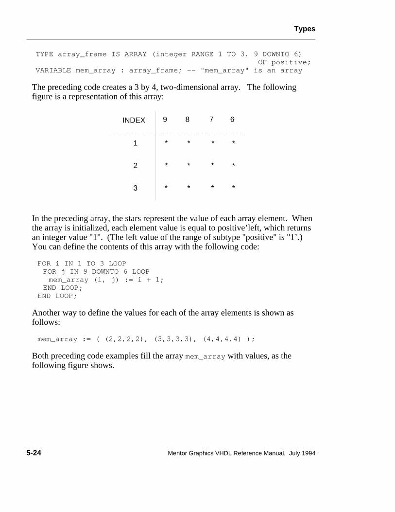
Types________________________________________________________________________________________________________________________
TYPE array_frame IS ARRAY (integer RANGE 1 TO 3, 9 DOWNTO 6) OF positive;VARIABLE mem_array : array_frame; -- "mem_array" is an array
The preceding code creates a 3 by 4, two-dimensional array. The followingfigure is a representation of this array:
INDEX
1
2
3
*
*
*
*
*
*
*
*
*
*
*
*
9 8 7 6
In the preceding array, the stars represent the value of each array element. Whenthe array is initialized, each element value is equal to positive’left, which returnsan integer value "1". (The left value of the range of subtype "positive" is "1’.)You can define the contents of this array with the following code:
FOR i IN 1 TO 3 LOOPFOR j IN 9 DOWNTO 6 LOOPmem_array (i, j) := i + 1;
END LOOP;END LOOP;
Another way to define the values for each of the array elements is shown asfollows:
mem_array := ( (2,2,2,2), (3,3,3,3), (4,4,4,4) );
Both preceding code examples fill the array mem_array with values, as thefollowing figure shows.
5-24 Mentor Graphics VHDL Reference Manual, July 1994

Types________________________________________________________________________________________________________________________
INDEX
1
2
3
2 2 2 2
3
4
3
4
3
4
3
4
9 8 7 6
The preceding array example shows you an example of a constrained array andsome of the syntax for declaring and manipulating a constrained array. An arraycan be either constrained or unconstrained, as the following pages describe. Thediagrams on page 5-23 show some of the related syntax for defining aconstrained or unconstrained array.
As indicated by the BNF descriptions on page 5-23 arrays have the followingcharacteristics:
● An array can be constrained or unconstrained.
● The range bounds can be of types other than integer types.
● You can specify the range bound type of a constrained array.
A constrained array is an array that has a specific subset of values for the range ofthe array indices. You saw an example of a constrained array on page 5-24. Ifyou specify a range using universal_integers or integer literals, the systemassumes these indices are a subset of the type integer (from package "standard").For example, the first line in the following code is equivalent to the second lineof code:
TYPE int_array IS ARRAY(1 TO 25) OF integer; --This is equiv.TYPE int_array IS ARRAY(integer RANGE 1 TO 25) --to this OF integer;
The most common array ranges are integer types. The range type for arrays doesnot have to be of type integer. However, the left and right bounds must be of thesame type. The range bounds can be any discrete type. For example:
Mentor Graphics VHDL Reference Manual, July 1994 5-25
Types________________________________________________________________________________________________________________________
TYPE month IS (jan, feb, mar, apr, may, jun, jly, aug, sep, oct, nov, dec);TYPE hours IS RANGE 0.0 TO 23.0;TYPE vacation IS ARRAY (month RANGE jun TO sep) OF hours;
In the previous example, the array vacation is a one-dimensional array type thatis constrained by a range of the enumerated type month. The elements of thearray are specified to be of the type hours, which are floating point numbers.
If constrained arrays were the only arrays allowed in VHDL, you could neverspecify two arrays that have the same type but different range bounds. This iswhy the unconstrained array exists.
An unconstrained array is an array in which you specify the type of the indicesbut do not specify the range. In place of specifying the range, you use the boxsymbol "<>". In this way you can declare the array type without declaring itsrange, and then you can declare as many arrays of the same type with the desiredrange. This allows you to pass arrays of arbitrary size as parameters. Figure 5-3shows this concept of unconstrained arrays.
The following example shows you the declaration of an unconstrained array andthe declaration of two arrays of the same type as the unconstrained array, whichcould possibly appear elsewhere in your code description:
TYPE data_array IS ARRAY (integer RANGE <>) OF integer;
--With the unconst. array declared, the following code can be --used in a hardware description.
VARIABLE address : data_array (0 TO 255);VARIABLE hex_code : data_array (255 TO 1023);
5-26 Mentor Graphics VHDL Reference Manual, July 1994

Types________________________________________________________________________________________________________________________
))
))
((
((
))
))
((
((
Constrained ArrayOf The Same Type
Constrained ArrayOf The Same Type
Unconstrained Array
Figure 5-3. Unconstrained Arrays
Summary of Array Type Rules
The following list is a summary of the rules that govern the use of arrays:
● All the elements in an array must be of the same type.
● The element types in an array can be only scalar, other array types, or recordtypes; no file types are allowed.
● If you use a subtype indication as a discrete range, the subtype indication mustnot contain a resolution function. For information on resolution functions,refer to page 11-10.
● You use index constraints for arrays, and you use range constraints forsubtypes.
Mentor Graphics VHDL Reference Manual, July 1994 5-27
Types________________________________________________________________________________________________________________________
Array Operations
There are several operations you can perform using arrays, through the use ofexpressions and specific array operations. You can extract a single array elementby specifying an index value in an expression. You specify an index by using anindexed name. For more information on indexed names, refer to page 3-8.
You can compare two arrays of the same type with relational operators. Formore information on expressions and operators, refer to Section 2.
You can concatenate one-dimensional arrays to form larger one-dimensionalarrays, as the following example shows:
PROCESS (sens_sig)TYPE ref_array IS ARRAY (natural RANGE <>) OF integer; VARIABLE x : ref_array (0 TO 899); -- Size is 900VARIABLE z : ref_array (0 TO 99); -- Size is 100VARIABLE comp_arry : ref_array (0 TO 999); -- Size is 1000
BEGINcomp_arry := x & z; -- concatenate the arrays, size is 1000
END PROCESS;
You concatenate the one-dimensional arrays using the concatenation operator"&". You can also concatenate an array with a single element value of the sametype. For a discussion on concatenation, refer to page 2-23.
You can also select a contiguous subset of a one-dimensional array by using aslice name. A slice name designates a portion of a one-dimensional array, as thefollowing example shows:
PROCESS (sens_sig)TYPE ref_array IS ARRAY (natural RANGE <>) OF integer; VARIABLE main_bus : ref_array (0 TO 255); --Declare arrays VARIABLE addr, data : ref_array (0 TO 127); --
BEGINaddr := main_bus (0 TO 127);data := main_bus (128 TO 255);
END PROCESS;
For more information on slice names and slicing arrays, refer to page 3-9.
5-28 Mentor Graphics VHDL Reference Manual, July 1994

Types________________________________________________________________________________________________________________________
record_type_definitionA record is a composite type whose elements can be of various types. The recordtype definition specifies a particular record type.
Construct Placementcomposite_type_definition, (type_definition, type_declaration -block_declarative_item, entity_declarative_item,package_body_declarative_item, package_declarative_item,process_declarative_item, subprogram_declarative_item )
Syntax
record_type_definition ::= record element_declaration { element_declaration } end record
element_declaration ::= identifier_list : element_subtype_definition ;
element_subtype_definition ::= subtype_indication
Definitions
■ element_declarationDeclares the subtypes of one or more record elements named in the identifierlist.
DescriptionA record type groups objects of different types so they can be operated on as asingle object. The record type definition contains of a series of elementdeclarations, each of which contains one or more element identifiers and asubtype indication for those elements. All the element identifiers must be unique.The following example shows two record type definitions.
Mentor Graphics VHDL Reference Manual, July 1994 5-29

Types________________________________________________________________________________________________________________________
TYPE coordinates IS RECORD xvalue,yvalue : integer;
END RECORD;
TYPE half_day IS (am, pm);TYPE clock_time IS RECORD
hour : integer RANGE 1 TO 12;minute,second : integer RANGE 1 TO 60;ampm : half_day;
END RECORD;
You can read from and assign data to individual elements of a record. To accessan individual record element, you use the selected name construct, as shown inthe following examples:
VARIABLE time_of_day : clock_time;. . .time_of_day.minute := 35; -- loads 35 into element "minute"
start_hour := time_of_day.hour; -- assigns value of element -- "hour" to "start_hour"
When assigning values to or reading from record elements, the types of therecord elements must match the types of the variables. You can also access arecord as an aggregate, in which case all the elements are assigned at once, asshown in the following example:
VARIABLE time_of_day : clock_time;VARIABLE start_hour : integer RANGE 1 TO 12;. . .time_of_day := (12, 05, 23, am);
5-30 Mentor Graphics VHDL Reference Manual, July 1994

Types________________________________________________________________________________________________________________________
access_type_definitionAccess types are types whose values point to other objects; they allow access toobjects such as FIFOs and linked lists that contain unnamed elements for whichstorage is dynamically allocated.
Construct Placementtype_definition, (type_declaration - block_declarative_item,entity_declarative_item, package_body_declarative_item,package_declarative_item, process_declarative_item,subprogram_declarative_item )
Syntax
access_type_definition ::= access subtype_indication
Definitions
■ subtype_indicationDefines the type of the objects pointed to by the access type. This subtype iscalled the designated subtype, and the base type is called the designated type.The designated type must not be a file type. The only kind of constraintallowed in the subtype indication is an index constraint.
DescriptionDeclaring an access type is a preliminary step to setting up an object called adesignator; such an object can be assigned access values that designate, or pointto, other unnamed objects containing values of the designated subtype. Once anaccess type has been declared, you can create a designator (hereafter called apointer) by declaring a variable of that type and then assigning an access value tothat variable using an allocator expression. Only variables can be declaredaccess types, and only variables may be pointed to by access values.
The following example illustrates the process of creating an access type, accessvalue, and pointer:
TYPE buff IS RANGE 0 TO 1023 ;
TYPE buff_ptr IS ACCESS buff ;
VARIABLE ptr1 : buff_ptr := NEW buff ’ (511) ;
Mentor Graphics VHDL Reference Manual, July 1994 5-31

Types________________________________________________________________________________________________________________________
This example accomplishes three things: First, it declares the type buff, that is,the type of object that will be pointed to. Second, it declares an access type,buff_ptr, of type buff. This access type is now available for variables that will beused as pointers to objects of type buff. Third, it declares a variable ptr1 ofaccess type buff_ptr and uses an allocator expression (the reserved word NEWfollowed by buff), which does three things:
● Allocates enough memory to store an object of type buff.
● Creates and assigns a value to an (unnamed) object of type buff. In this case,an initial value of 511 is assigned to the object.
● Assigns an access value (address) to ptr1, which can then be used to referencethe object. You can also initialize a pointer variable to a value of null withoutusing an allocator expression, as shown in the following example. In this casethe pointer points to no object.
VARIABLE ptr1 : buff_ptr := NULL ;
The use of allocators is discussed in more detail in Section 2 of this manual,under Allocators, beginning on page 2-13. The following subsection discussesincomplete type declarations and their use with access types in creatingself-referencing structures such as linked lists.
Incomplete Types
An incomplete type declaration names a type without specifying anything elseabout the type. You can use this kind of type declaration with access types tocreate interdependent, self-referencing structures such as linked lists. Thefollowing restrictions apply to incomplete type declarations:
● Each incomplete type declaration must have a corresponding full typedeclaration with the same identifier.
● The corresponding full type declaration must occur within the samedeclarative part as the incomplete type declaration.
● Between the incomplete type declaration and the end of the corresponding fulltype declaration, you can use the name of the incomplete type only as a typemark in the subtype indication of an access type definition. No constraints areallowed in the subtype indication.
5-32 Mentor Graphics VHDL Reference Manual, July 1994

Types________________________________________________________________________________________________________________________
The following example shows how an incomplete type declaration is used:
TYPE dl_data IS RANGE (0 TO 255) ;TYPE dl_block IS ARRAY ( 0 TO 7 ) OF dl_data ;
TYPE dl_pntr ; -- Incomplete type declaration
TYPE dl_record IS RECORDdata_block : dl_block ;next_rec : dl_pntr; -- The incomplete type is used here.
END RECORD ;
-- The following declaration completes the declaration of -- dl_pntr as an access type to objects of type dl_record.
TYPE dl_pntr IS ACCESS dl_record; -- Complete type declaration
This example declares a record type to hold data in a linked-list structure. Atsame time it sets up a pointer that will be used to gain access to the elements ofthe linked list. Notice that the record type for the list elements (beginning TYPEdl_record IS RECORD) consists of two parts: an array of integers( data_block) that holds the data; and a pointer (next_rec) to the next elementof the list. The pointer needs to be an access type, which can be assigned anaccess value that points to the location of the next list element.
Notice that without an incomplete type declaration, you would be unable toinclude the pointer as part of the structure that it refers to. You must first use anincomplete type declaration to make the name of the access type available to therecord type declaration. Once the record type has been declared, you completethe declaration of the access type, which can now refer to the record type.
For additional information on access types, refer to the preceding subsection,access_type_definition. For a formal syntax description of both full andincomplete type declarations, refer to type_declaration on page 4-4.
Mentor Graphics VHDL Reference Manual, July 1994 5-33

Types________________________________________________________________________________________________________________________
file_type_definitionThe file type definition defines data types for use in file declarations.
Construct Placementtype_definition, (type_declaration - block_declarative_item,entity_declarative_item, package_body_declarative_item,package_declarative_item, process_declarative_item,subprogram_declarative_item )
Syntax
file_type_definition ::= file of type_mark
Definitions
■ type_markDefines the type of the values contained in the file.
DescriptionFiles may be read-only or write-only, but not both. Some uses of file types arethe following:
● Logging and tracing error conditions
● Collecting data for statistics
● Loading the contents of memory with data
● Loading test vectors for your model
The following examples show the declaration of file types:
TYPE rom_data IS FILE OF integer;TYPE error_file IS FILE OF string;TYPE input_data IS FILE OF bit_vector;
When you declare a file type with a type mark that is scalar or a constrained arraysubtype, read and write procedures and an endfile function are implicitly definedimmediately following the file type declaration. For more information on filedeclarations, refer to page 4-18. The following example shows the declaration of
5-34 Mentor Graphics VHDL Reference Manual, July 1994

Types________________________________________________________________________________________________________________________
a file type, a file declaration, and the implicit subprogram definitions that aredeclared by the system.
TYPE stat IS FILE OF integer; -- file type decl.FILE my_stats : stat IS "stat_file"; -- file decl.
-- implicit definitions
PROCEDURE read (VARIABLE my_stats : INOUT stat; value : OUT integer); PROCEDURE write (my_stats: INOUT stat; value: IN integer); FUNCTION endfile(VARIABLE my_stats: IN stat) RETURN boolean;
The read procedure returns a value from the file you specify, allowing you to doa file read. The write procedure appends a value to the file you specify,allowing you to do a file write. The endfile function returns a Boolean value ofTRUE when a read operation cannot return another value from the file; otherwisethe function returns a value of FALSE. An error condition exists if a read ismade on a file that has an endfile value of TRUE.
The content of value is the value of the item in the file. This value must be thesame type as the file. In the preceding example, value in the read and writeprocedures must be of type integer. In the following example, value in the readprocedure must be an array of type real.
The following example shows a file type that has an unconstrained array type as atype mark, and the implicit read procedure that follows. The write andendfile operations are the same as the previous example.
TYPE rom_array IS ARRAY (integer RANGE <>) OF real; --uncons.TYPE data_values IS FILE OF rom_array; --file type decl.FILE rval : data_values IS my_file; -- file declaration
PROCEDURE read (VARIABLE rval: INOUT data_values; value: OUT rom_array; length: OUT natural); -- implicit read def.
The read procedure from the preceding example returns a value from the file anda parameter called length that specifies the actual length of the array value read.For information on file objects and their declaration, refer to page 4-18.
Mentor Graphics VHDL Reference Manual, July 1994 5-35

Statements________________________________________________________________________________________________________________________
Section 6Statements
This section discusses the statements that you can use in VHDL. A statement is aconstruct you use to specify one or more actions to take place in a hardwaredescription. These actions can take place one after another (sequentially) or atthe same time (concurrently). The following list shows the topics and constructsexplained in this section:
Statement Classes 6-2sequential_statement 6-5concurrent_statement 6-7
Statement Quick Reference 6-8
assertion_statement 6-10
block_statement 6-12
case_statement 6-15
component_instantiation_statement 6-17
concurrent_assertion_statement 6-19
concurrent_procedure_call 6-21
concurrent_signal_assignment_stmnt 6-23conditional_signal_assignment 6-25selected_signal_assignment 6-27
exit_statement 6-28
generate_statement 6-30
if_statement 6-34
loop_statement 6-36
Mentor Graphics VHDL Reference Manual, July 1994 6-1

Statements________________________________________________________________________________________________________________________
next_statement 6-38
null_statement 6-39
procedure_call_statement 6-40
process_statement 6-41
return_statement 6-44
signal_assignment_statement 6-46
variable_assignment_statement 6-48
wait_statement 6-49
Statement ClassesThere are two classes of statements you can use in your VHDL descriptions:
● Sequential statements
● Concurrent statements
The following example illustrates the difference between sequential andconcurrent statement execution:
p1: PROCESS (a, b, c) BEGIN --sequential area a <= b AND c; d <= a AND c;END PROCESS p1;
b1: BLOCKBEGIN --concurrent area a <= b AND c; d <= a AND c;END BLOCK b1;
In this example, the code in the left-hand column contains two sequential signalassignments within a process labeled p1. In the right-hand column of theexample, two concurrent signal assignments within block b1 perform the samefunctions as the statements in p1.
Statements within a process must be sequential statements; they are evaluated inthe order in which they appear in the code. In contrast, statements within thestatement part of a block must be concurrent statements. During simulation,
6-2 Mentor Graphics VHDL Reference Manual, July 1994

Statements________________________________________________________________________________________________________________________
concurrent statements are evaluated as if they occur simultaneously. Thus, thesignal assignments in p1 occur one after the other, while the signal assignmentsin b1 occur simultaneously.
For more information on how sequential and concurrent statements are evaluated,refer to the Mentor Graphics Introduction to VHDL, the "Contrasting Concurrentand Sequential Modeling subsection".
Figure 6-1 shows where statements belong in the language hierarchy, and it liststhe available concurrent and sequential statements.
Several of the statements (and other constructs) use the "label" construct. Rulesfor using the label with each construct are discussed in the appropriatesubsection. The following BNF description shows that a label is an identifier:
label ::= identifier
Mentor Graphics VHDL Reference Manual, July 1994 6-3

Statements________________________________________________________________________________________________________________________
����������������������������������������������������������������������������������������������������������������������������������������������������������������������������������������������������������������������������������������������������������������������������������������������������������������������������������������������������������������������������������������������������������������������������������������������������������������������������������������������������������������������������������������������������������������������������������������������������������������������������������������������������������������������������������������������������������������������������������������������������������������
Concurrent Statements
Statements
Sequential Statements
WaitAssertion
Signal AssignmentProcedure Call
BlockProcess
Concurrent Procedure CallConcurrent Assertion
Concurrent Signal AssignmentComponent Instantiation
Generate
SignalsTypes
Configurations
Design Entities
ComponentsAttributes
Packages
Naming, Scope, and Visibility
Lexical Elements
Expressions
Design Units
Subprograms
Declarations
Statements
If ExitCase ReturnLoop NullNext
Figure 6-1. Statements
6-4 Mentor Graphics VHDL Reference Manual, July 1994

Statements________________________________________________________________________________________________________________________
sequential_statement Sequential statements represent hardware algorithms that define the behavior of adesign.
Construct Placementprocess_statement_part, subprogram_statement_part,sequence_of_statements, (if_statement, loop_statement,case_statement_alternative, - case_statement )
Syntax
sequential_statement ::= wait_statement | assertion_statement | signal_assignment_statement | variable_assignment_statement | procedure_call_statement | if_statement | case_statement | loop_statement | next_statement | exit_statement | return_statement | null_statement
DescriptionYou can use sequential statements only inside a process statement or within asubprogram (procedure or function). Each statement executes in the order inwhich it is encountered. The preceding BNF description listed the sequentialstatements available in VHDL.
Sequential statements are divided into categories, based on their operation. Thefollowing list shows the categories for the sequential statements.
● Assignment statements. These statements provide you with a method forchanging the value of variables and signals. The statements include thefollowing:
❍ Variable assignment statement
❍ Signal assignment statement
Mentor Graphics VHDL Reference Manual, July 1994 6-5

Statements________________________________________________________________________________________________________________________
● Conditional statements. These statements provide you with a method ofcontrolling the execution of other sequential statements. This control dependson the resulting value of an expression. The statements include the following:
❍ Case statement
❍ If statement
❍ Wait statement
● Iterative statements. These statements provide you with a method ofexecuting a sequence of statements repeatedly. The statements include thefollowing:
❍ Loop statement
❍ Next statement (Also controls loop iteration)
❍ Exit statement (Also controls loop iteration)
● Procedure control statements. These statements provide you with a method ofcontrolling subprogram execution. The statements include the following:
❍ Procedure call statement
❍ Return statement
● Miscellaneous statements. These statements include:
❍ Assertion statement
❍ Null statement
6-6 Mentor Graphics VHDL Reference Manual, July 1994

Statements________________________________________________________________________________________________________________________
concurrent_statementConcurrent statements define blocks and processes that are connected together todescribe the general behavior or structure of a design. You can think ofconcurrent statements as processes that exist in parallel, waiting for a specifiedcondition to be satisfied before executing.
Construct Placementarchitecture_statement_part, block_statement_part
Syntax
concurrent_statement ::= block_statement | process_statement | concurrent_procedure_call | concurrent_assertion_statement | concurrent_signal_assignment_stmnt | component_instantiation_statement | generate_statement
DescriptionYou use the block statement to group together other concurrent statements. Themain concurrent statement is the process statement, which defines a sequentialoperation representing a part of the design. The remaining concurrent statements(except for the component instantiation statement) provide you with a shorthandmethod for specifying processes that commonly occur. These statements use animplied process that is automatically created by the system.
The preceding BNF description shows the concurrent statements that areavailable in VHDL. The ability to express concurrent action is especiallyimportant when you model logic circuits. The reason for this is that logic circuitsoften work in parallel, where a change in one signal can propagate throughseveral devices at the same time.
Mentor Graphics VHDL Reference Manual, July 1994 6-7

Statements________________________________________________________________________________________________________________________
Statement Quick ReferenceTable 6-1 is a quick reference table that lists all the VHDL statements. The tableheading descriptions for this table follow:
● Statement: the name of the statement
● Reserved Words: the reserved words used in the statement, if any
● Class: "Con." indicates a concurrent statement classification "Seq." indicatesa sequential statement classification.
● Description: a brief description of the statement
Table 6-1. System-1076 Statements
StatementReservedWords Class Description
Assertion assertreportseverity
Seq. Checks if specified condition is true, andif so, reports a message and a severitylevel
Block blockbeginend
Con.Defines an internal block, and groupsconcurrent statements together
Case caseisend
Seq.Selects one of a number of statementsequences for execution
ComponentInstantiation
None Con.
Instantiates a subcomponent within adesign entity
Concurrent Assertion
assertreportseverity
Con.Represents a process statementcontaining an assertion statement
ConcurrentProcedureCall
NoneCon.
Represents a process containing thecorresponding sequential procedure call
ConcurrentSignalAssignment
guardedtransport Con.
Represents an equivalent processstatement that assigns values to a signal
6-8 Mentor Graphics VHDL Reference Manual, July 1994

Statements________________________________________________________________________________________________________________________
Table 6-1. System-1076 Statements [continued]
StatementReservedWords Class Description
Assertion assertreportseverity
Seq. Checks if specified condition is true, andif so, reports a message and a severitylevel
Exit exitwhen
Seq. Exits from an enclosing loop statement
Generate generateend
Con. Generates a regular structure, such as aregister, within a structural description
If ifthenelsifend
Seq.Selects 0 or 1 of the enclosed sequentialstatements for execution
Loop loopend
Seq. Iteractively executes a sequence ofstatements
Next nextwhen
Seq. Completes the execution of one of theiterations of an enclosing loop statement
Null null Seq. Specifies no action is to be performed;passes execution to the next statement
ProcedureCall
None Seq. Executes a particular procedure body
Processprocessbeginend
Con.Defines an independent sequentialprocess, representing the behavior of aportion of a design
Return return Seq. Completes execution of the innermostenclosing function or procedure
Signal Assignment
NoneSeq.
Modifies projected output waveform inthe driver of a signal
VariableAssignment
None Seq. Replaces current variable value with anew value
Wait waiton
Seq. Suspends a process or procedure
Mentor Graphics VHDL Reference Manual, July 1994 6-9

Statements________________________________________________________________________________________________________________________
assertion_statementThe assertion statement checks a condition you specify to determine if it is true,and can report a message with a specified severity if the condition is not true.There is also a concurrent assertion statement, which is defined on page 6-19.
Construct Placementsequential_statement, (process_statement_part, subprogram_statement_part,sequence_of_statements)
Syntax
assertion_statement ::= assert condition [ report expression ] [ severity expression ] ;
DescriptionWhen you use a report expression, it must include an expression of thepredefined type string that specifies a message to be reported. If you do notspecify a report expression, a default value of "assertion violation" is used forthis string.
When you use a severity expression, it must specify an expression of thepredefined type severity_level that specifies to what degree the severity of theassertion condition exists. If you do not specify a severity expression, a defaultvalue of ERROR is used for the severity_level.
The types string and severity_level are predefined in package "standard", whichis discussed on page 9-18.
The following list shows the predefined severity levels from least to mostsevere.
● NOTE: use for general information messages.
● WARNING: use for a possible undesirable condition.
● ERROR: use for a task completed with the wrong results.
● FAILURE: use for a task that is not completed.
6-10 Mentor Graphics VHDL Reference Manual, July 1994

Statements________________________________________________________________________________________________________________________
ExampleThe following example shows how to use assertion statements to report setup-time and pulse-width violations on a synchronous device. ASSERT NOT (clock’event AND clock = ’1’ AND preset = ’1’ AND NOT(preset’stable(20 ns))) REPORT "Setup time violation" SEVERITY warning;
This statement asserts that when the clock changes to a high and the delayedpreset signal is a "one" and remains stable for 20 ns, the setup time is not inviolation. However, if the assertion fails, a "Setup time violation" warning isgenerated.
ASSERT (preset’delayed = ’1’ AND preset = ’0’ AND preset’delayed’last_event >= 25 ns) REPORT "Pulse width violation" SEVERITY warning;
The preceding example asserts that when preset changes from a high to a low andthe preset signal stays in the same state for at least 25 ns, the pulse width is not inviolation. If the assertion fails, a "Pulse width violation" warning is generated.
The items that follow the tic mark (’) are predefined signal attributes. For moreinformation on signal attributes, refer page 10-28.
Mentor Graphics VHDL Reference Manual, July 1994 6-11

Statements________________________________________________________________________________________________________________________
block_statementThe block statement groups together other concurrent statements, forming aninternal block that represents a section of a design description. You can nestinternal blocks hierarchically to organize your design.
Construct Placementconcurrent_statement, (architecture_statement_part, block_statement_part)
Syntax
block_statement ::= block_label : block [ ( guard_expression ) ] block_header block_declarative_part begin block_statement_part end block [ block_label ] ;
block_header ::= [ generic_clause [ generic_map_aspect ; ] ] [ port_clause [ port_map_aspect ; ] ]
block_declarative_part ::= { block_declarative_item }
6-12 Mentor Graphics VHDL Reference Manual, July 1994

Statements________________________________________________________________________________________________________________________
block_declarative_item ::= subprogram_declaration | subprogram_body | type_declaration | subtype_declaration | constant_declaration | signal_declaration | file_declaration | alias_declaration | component_declaration | attribute_declaration | configuration_specification | attribute_specification | disconnection_specification | use_clause
block_statement_part ::= { concurrent_statement }
Definitions
■ guard_expression An expression of type boolean that you can use to control the execution ofthe concurrent signal assignment statements within a block.
DescriptionYou use a hierarchy of blocks to describe a design entity, which in turn describesa portion of a complete design. The highest level block in this hierarchy is thedesign entity itself, which is an external block residing in a library. You can usethis external block as an element in other designs. The block statement, however,describes the internal blocks of your design.
You use the block label to help you keep track of the different internal blocks ofyour design. The block label at the end of the block statement is optional.However, if you use a block label here, it must match the block label at thebeginning of the block statement.
You can specify a guard expression of type boolean to control the execution ofthe concurrent signal assignment statements within a block. When you use this
Mentor Graphics VHDL Reference Manual, July 1994 6-13

Statements________________________________________________________________________________________________________________________
expression, the system automatically declares a signal with a simple name of"guard" of type boolean. The signal "guard" can be passed as an actual signal ina component instantiation statement. The topic of guarded signals is discussed indetail on page 11-5.
In the block header, you can define ports and generics for a block. This definitionallows you to map signals and generics external to the block to those containedwithin the block. For additional information refer to the port_clause,port_map_aspect, generic_clause, and generic_map_aspect discussions in Section8.
You can specify zero or more block declarative items in a block statement.These items are declarations that are used within the block. Block declarativeitems can also be declared in the architecture declarative part and are discussed inthat subsection on page 8-17.
The block statement part contains zero or more concurrent statements.
ExampleThe following example shows the possible use of a block statement:
ARCHITECTURE data_flow OF test IS SIGNAL clk, a, b, c : bit;BEGINsig_assign: -- block label BLOCK (clk = ’1’) -- guard expression SIGNAL z : bit; -- block_declarative_item BEGIN z <= GUARDED a; -- z gets a if "clk" = ’1’ END BLOCK sig_assign;END data_flow;
6-14 Mentor Graphics VHDL Reference Manual, July 1994

Statements________________________________________________________________________________________________________________________
case_statementThe case statement selects one or more sets of sequential statements for executiondepending on on the result of an expression.
Construct Placementsequential_statement, (process_statement_part, subprogram_statement_part,sequence_of_statements)
Syntax
case_statement ::= case expression is case_statement_alternative { case_statement_alternative } end case ;
case_statement_alternative ::= when choices => sequence_of_statements
sequence_of_statements ::= { sequential_statement }
DescriptionThe following list shows the rules for using the case statement:
● The expression must be an integer, enumeration, or one-dimensional characterarray type.
● Each choice in the case statement alternative must be the same type as theexpression you use.
● All the possible values of the expression must appear in the choices for thecase statement and must be of the same type as the expression (and locallystatic).
● You can use each choice only once.
You use the choice of others to represent any values of the expression that youdo not list in the case statement alternative. This choice must be the lastalternative. The reserved word others must be the only choice in this situation.The following example shows an illegal use of others:
Mentor Graphics VHDL Reference Manual, July 1994 6-15

Statements________________________________________________________________________________________________________________________
CASE slt ISWHEN ’1’ => sctl <= false;WHEN ’0’ | OTHERS => sctl <= true; --Illegal. More than one
END CASE; --choice when using OTHERS
Example
The following example shows a use of the case statement:
CASE (traffic_sensor) IS --"traffic_sensor" is expressionWHEN "00" => color <= red; --Case statement WHEN "01" => color <= yellow; --alternativesWHEN "10" => color <= green; --WHEN OTHERS => color <= flashing;--
END CASE;
The preceding example states the following: assign the signal color a value depending on the value of the expressiontraffic_sensor.
6-16 Mentor Graphics VHDL Reference Manual, July 1994
Statements________________________________________________________________________________________________________________________
component_instantiation_statementThe component instantiation statement creates an instance of a subcomponentwithin a design entity, connects signals to that subcomponent, and associatesgenerics in the design entity with generics in the subcomponent.
Construct Placementconcurrent_statement, (architecture_statement_part, block_statement_part)
Syntax
component_instantiation_statement ::= instantiation_label : component_name [ generic_map_aspect ] [ port_map_aspect ] ;
Definitions
■ instantiation_label A unique identifier that you supply to identify the component instance.
■ component_nameThe name of the component (from the component declaration) that is beinginstantiated.
DescriptionUsing component instantiation statements, along with component declarationsand signals, allows you to decompose a structural design into subcomponents.The instantiated subcomponents must be bound to external design entities thatdetermine the behavior of the subcomponents. You can alter the characteristicsof a design at any point in the design process by binding different design entitiesto the subcomponents. The topic of components and their use is discussedbeginning on page 8-20.
The following list shows the rules and information for using the componentinstantiation statement:
● The component name you use must be the name of a component you declarein the component declaration.
Mentor Graphics VHDL Reference Manual, July 1994 6-17

Statements________________________________________________________________________________________________________________________
● The optional generic map aspect associates a single actual with each localgeneric in the component declaration. Each of these local generics must beassociated exactly once.
● The optional port map aspect associates a single actual with each local port inthe component declaration. Each of these local ports must be associatedexactly once.
For information on the generic and port map aspect, refer to page 8-32.
ExampleThe following example shows the declaration of three components and theinstantiation of these components using component instantiation statements:
ENTITY mux ISPORT (a0, a1, sel : IN bit; y : OUT bit);
END mux;
ARCHITECTURE structure_descript OF mux ISCOMPONENT and2 --component declaration for "and2"PORT (a, b : IN bit; z : OUT bit); --local port clause
END COMPONENT;
COMPONENT or2 --component declaration for "or2" PORT (a, b : IN bit; z : OUT bit);
END COMPONENT;
COMPONENT inv --component declaration for "inv" PORT (i : IN bit; z : OUT bit);
END COMPONENT;
SIGNAL aa, ab, nsel : bit; -- signal declarationFOR U1 : inv USE ENTITY WORK.invrt(behav);--configurationFOR U2, U3: and2 USE ENTITY WORK.and_gt(dflw);--specif.FOR U4, : or2 USE ENTITY WORK.or_gt(arch1);--
BEGIN U1: inv PORT MAP (sel,nsel); --Instantiation of the U2: and2 PORT MAP (a0,nsel,aa); --components using componentU3: and2 PORT MAP (a1,sel,ab); --instantiationU4: or2 PORT MAP (aa,ab,y); --statements
END structure_descript;
6-18 Mentor Graphics VHDL Reference Manual, July 1994

Statements________________________________________________________________________________________________________________________
concurrent_assertion_statementThe concurrent assertion statement is an equivalent process statement generatedby the system that contains a sequential assertion statement and a wait statementat the end. This equivalent process is a passive process, because it has no signalassignment statements. For more information on the sequential assertionstatement, refer to page 6-10.
Construct Placemententity_statement, concurrent_statement, (architecture_statement_part,block_statement_part)
Syntax
concurrent_assertion_statement ::= [ label : ] assertion_statement
DescriptionExcept for the optional label, the syntax for this statement is the same as for thesequential assertion statement . The system knows when to create a concurrentassertion by the location in which the assertion statement appears, becauseconcurrent statements are allowed only in architectures or blocks.
If you specify an operand that is a signal in the expression of the assertionstatement, the signal’s longest static prefix name appears in the sensitivity list ofthe implied wait statement. If you specify an operand in the expression that is nota signal, no sensitivity clause, condition clause, or timeout clause appears in theimplied wait statement. For more information on the wait statement, refer topage 6-49.
A guarded signal has no effect on the assertion evaluation unless the guardedsignal appears in the assertion condition.
Mentor Graphics VHDL Reference Manual, July 1994 6-19

Statements________________________________________________________________________________________________________________________
ExampleThe following example shows a concurrent assertion statement and the equivalentprocess statement that the system creates.
ARCHITECTURE test OF parts ISBEGIN sig_check : --Label ASSERT preset = 1 AND clk = 1 --Concurrent assertion stmnt REPORT "Output Change Allowed" SEVERITY note;END test;
-- equivalent process
PROCESS BEGIN ASSERT preset = 1 AND clk = 1 REPORT "Output Change Allowed" SEVERITY note; WAIT ON preset, clk; --Sensitivity list formed by signalsEND PROCESS; --in the assertion condition expres.
6-20 Mentor Graphics VHDL Reference Manual, July 1994

Statements________________________________________________________________________________________________________________________
concurrent_procedure_callThe concurrent procedure call statement is an equivalent process statementgenerated by the system that contains a sequential procedure call and a waitstatement at the end. For more information on the sequential procedure callstatement, refer to page 6-40.
Construct Placemententity_statement, concurrent_statement, (architecture_statement_part,block_statement_part)
Syntax
concurrent_procedure_call ::= [ label : ] procedure_call_statement
DescriptionThe syntax for this statement is the same as for the sequential procedure callstatement, except for the optional label. The system knows when to create aconcurrent procedure call by the location of the procedure call statement, becauseconcurrent statements are allowed only in internal and external blocks.
The concurrent procedure call is a shorthand way to declare procedures thatrepresent commonly used processes, by calling the procedure as a concurrentstatement; the equivalent process is automatically created by the system. Theimplied wait statement gets its sensitivity list from signals of mode in or inoutfrom the actual part of any association element in the concurrent procedure call.Any other condition produces no sensitivity clause. For more information on thewait statement, refer to page 6-49.
A guarded signal has no effect on the concurrent procedure call statementevaluation unless the guarded signal appears in association list of the actualparameter part construct.
A concurrent procedure call appearing in an entity-statement part must bepassive.
Mentor Graphics VHDL Reference Manual, July 1994 6-21

Statements________________________________________________________________________________________________________________________
ExampleThe following example shows a procedure declaration, a concurrent procedurecall, a small procedure body, and the equivalent process that the system creates:
ARCHITECTURE test OF parts ISSIGNAL clock, tester : bit;CONSTANT offsets : real := 0.5;PROCEDURE test_vectors (SIGNAL clk : IN bit; --proced. SIGNAL test : INOUT bit; --decl. CONSTANT offset: IN real := 0.5);
PROCEDURE test_vectors (SIGNAL clk : IN bit; --proced. SIGNAL test : INOUT bit; --body CONSTANT offset: IN real := 0.5) IS BEGIN NULL; -- ummy body for exampleEND;
BEGIN
test_vectors (clock, tester, offsets); --con. proced. call
PROCESS -- equivalent processBEGIN test_vectors (clock, tester, offsets); WAIT ON clock, tester; --sens. list formed by in and END PROCESS; --inout signals
END test;
6-22 Mentor Graphics VHDL Reference Manual, July 1994

Statements________________________________________________________________________________________________________________________
concurrent_signal_assignment_stmntThe concurrent signal assignment statement is an equivalent process statementgenerated by the system that assigns values to signals.
Construct Placementconcurrent_statement, (architecture_statement_part, block_statement_part)
Syntax
concurrent_signal_assignment_statement ::= [ label : ] conditional_signal_assignment | [ label : ] selected_signal_assignment
options ::= [ guarded ] [ transport ]
DescriptionThe concurrent signal assignment can take two forms:
● Conditional signal assignment
● Selected signal assignment
The following rules apply to both forms of the concurrent signal assignmentstatement:
● You cannot use a null waveform element on the right-hand side of theconcurrent signal assignment. An error occurs if this is the case.
● If you use a concurrent signal assignment that has a static target and staticwaveforms, the equivalent process that the system creates includes a waitstatement with no sensitivity list. This means the equivalent process executesone time during the start of the simulation and suspends action permanently.
● You can use the reserved word guarded or transport, or both as options inthe concurrent signal assignment statements you use.
The option guarded controls the execution of the signal assignment throughone of the following:
Mentor Graphics VHDL Reference Manual, July 1994 6-23
Statements________________________________________________________________________________________________________________________
❍ An implied guard signal declared through a guard expression on a block
❍ An explicitly declared signal of type boolean that you supply
The signal assignment is made when the guard value changes from FALSE toTRUE, or when the guard is at a TRUE value and an event occurs on a guardsignal input. The topic of guarded signals is discussed in detail on page 11-5.
When you use the option transport, you specify that the signal assignmenthas transport delay. Transport delay means that any pulse is transmitted to thesignal with no regard to how short the pulse width or duration. The topic oftransport delay is discussed in detail on page 11-19.
The following subsections discuss the two forms of the concurrent signalassignment statements.
6-24 Mentor Graphics VHDL Reference Manual, July 1994

Statements________________________________________________________________________________________________________________________
conditional_signal_assignmentThe conditional signal assignment form of the concurrent signal assignmentstatement results in an equivalent process statement generated by the system thatassigns values to signals using an "if" statement format.
Construct Placementconcurrent_signal_assignment_statement, (concurrent_statement, -architecture_statement_part, block_statement_part)
Syntax
conditional_signal_assignment ::= target <= options conditional_waveforms ;
conditional_waveforms ::= { waveform when condition else } waveform
DescriptionBecause of the similarity in appearance of the assignment operator and the "lessthan or equal" operator, both of which are written <=, you should be careful thatyour code does not produce unexpected results. For example, the intent of thesignal assignment statement in the following code was this: "If en1 is 1, assigndata_a to test. If en2 is 1, assign data_b to test. If neither of the above is true,assign 1 to test."
ENTITY tester ISEND tester;
ARCHITECTURE data_flow OF tester IS SIGNAL test, data_a, data_b : qsim_state; SIGNAL en1, en2 : bit;BEGIN test <= data_a AFTER 2 ns WHEN en1 = ’1’ ELSE test <= data_b AFTER 2 ns WHEN en2 = ’1’ ELSE test <= ’1’ AFTER 2 ns;
END data_flow; However, the following example shows what the preceding example actuallydoes. This example evaluates certain relational expressions ("test less than or
Mentor Graphics VHDL Reference Manual, July 1994 6-25

Statements________________________________________________________________________________________________________________________
equal to data_b", and so on) and then assigns the boolean result of the expressionto the signal test.
ENTITY tester ISEND tester;
ARCHITECTURE data_flow OF tester IS SIGNAL test, data_a, data_b : qsim_state; SIGNAL en1, en2 : bit;BEGIN test <= (data_a) AFTER 2 ns WHEN en1 = ’1’ ELSE (test <= data_b) AFTER 2 ns WHEN en2 = ’1’ ELSE ( test <= ’1’) AFTER 2 ns; END data_flow;
The following example, although similar to the first example, shows a valid useof a conditional signal assignment:
ARCHITECTURE data_flow OF tester IS SIGNAL test, data_a, data_b : my_qsim_state; SIGNAL en1, en2 : bit;BEGIN bus_test : BLOCK BEGIN --The following code shows cond. sig. assignments test <= TRANSPORT data_a AFTER 2 ns WHEN en1 = ’1’ ELSE data_b AFTER 2 ns WHEN en2 = ’1’ ELSE ’1’ AFTER 2 ns; END BLOCK bus_test;END data_flow;
Using the preceding example, the following example shows the equivalentprocess the system creates for the conditional signal assignment.
PROCESS (data_a, data_b, en1, en2) --sens. list createdBEGIN --from all signalsIF en1 = ’1’ THEN test <= TRANSPORT data_a AFTER 2 ns; ELSIF en2 = ’1’ THEN test <= TRANSPORT data_b AFTER 2 ns;ELSE test <= TRANSPORT ’1’ AFTER 2 ns;END IF;
END PROCESS;
6-26 Mentor Graphics VHDL Reference Manual, July 1994
Statements________________________________________________________________________________________________________________________
selected_signal_assignmentThe selected signal assignment form of the concurrent signal assignmentstatement results in an equivalent process statement generated by the system thatassigns values to signals using a "case" statement format.
Construct Placementconcurrent_signal_assignment_statement, (concurrent_statement,architecture_statement_part, block_statement_part)
Syntax
selected_signal_assignment ::= with expression select target <= options selected_waveforms ;
selected_waveforms ::= { waveform when choices , } waveform when choices
ExampleThe following example shows a possible use of the selected signal assignment.
ARCHITECTURE data_flow OF tester ISSIGNAL test, data_a, data_b : my_qsim_state;SIGNAL en1 : bit;
BEGINWITH en1 SELECTtest <= data_a WHEN ’0’, data_b WHEN ’1’;
END data_flow;
Using the previous example, the following example shows the equivalent formthe system creates for the selected signal assignment.
PROCESS (test, data_a, data_b, en1) --sens. list createdBEGIN --from all signalsCASE en1 ISWHEN ’0’ => test <= data_a;WHEN ’1’ => test <= data_b;
END CASE;END PROCESS;
Mentor Graphics VHDL Reference Manual, July 1994 6-27

Statements________________________________________________________________________________________________________________________
exit_statementThe exit statement relates to the loop statement in that you use this statement toleave an enclosing loop. After execution of the exit statement, control goes to thepoint immediately following the exited loop.
Construct Placementsequential_statement, (process_statement_part, subprogram_statement_part,sequence_of_statements)
Syntax
exit_statement ::= exit [ loop_label ] [ when condition ] ;
DescriptionAs the BNF description shows, the exit statement can take several forms. Forexample:
EXIT; --Leave the nearest enclosing loop.EXIT sum_data; --Leave loop named by loop_label "sum_data"EXIT WHEN data = 1024; --Leave enclosing loop if condition --"data = 1024" is true.EXIT fill_memory WHEN enable = 1; --Leave named loop if the --condition "enable = 1" is true
An exit statement with a loop label is valid only within a loop that has acorresponding label. You can use an exit statement in a loop that does not have aloop label. In this case, the statement applies only to the innermost enclosingloop.
If the condition you use evaluates to FALSE, the exit statement has no effect.
6-28 Mentor Graphics VHDL Reference Manual, July 1994

Statements________________________________________________________________________________________________________________________
ExampleThe following example shows the exit statement in a nested loop structure.
sum_data: --Loop label for outer loopWHILE count < 10 LOOP
-- sequence of sequential statements
eval_data: --Loop label for inner loopFOR i IN 0 TO 10 LOOP
-- sequence of sequential statements
EXIT sum_data WHEN i = a; --Exit outer loop on the condition
-- sequence of sequential statements
END LOOP eval_data;END LOOP sum_data;
In the preceding example, if you change the exit statement to the following, theinner loop exits on the condition and remains in the loop sum_data.
EXIT eval_data WHEN i = a;
Mentor Graphics VHDL Reference Manual, July 1994 6-29

Statements________________________________________________________________________________________________________________________
generate_statementGenerate statements efficiently model regular structures, such as registers andmultiplexers, in structural design descriptions. A generate statement can replicatea block of concurrent statements a specified number of times or can conditionallycreate a block of concurrent statements.
Construct Placementconcurrent_statement (architecture_statement_part, block_statement_part,generate_statement)
Syntax
generate_statement ::= generate_label : generation_scheme generate { concurrent_statement } end generate [ generate_label ] ;
generation_scheme ::= for generate_parameter_specification | if condition
parameter_specification ::= identifier in discrete_range
Definitions
■ generate_labelIdentifies the generate statement. If a label appears at the end of the generatestatement, it must repeat the generate label.
■ generation_schemeA for generation scheme specifies how many times a block of concurrentstatements is to be replicated. An if generation scheme causes one replicationif the condition expression evaluates to TRUE; otherwise, it generates norepetitions.
■ parameter_specificationIn a for generation scheme, defines the generate parameter. The generateparameter takes on each value in the specified discrete range as the
6-30 Mentor Graphics VHDL Reference Manual, July 1994
Statements________________________________________________________________________________________________________________________
concurrent-statement block is replicated (generated) once for each value inthe specified discrete range. The generate parameter acts as a constantwhose value may be read; it has meaning only within the generate statementit applies to.
Description
You can describe repetitive structures in a structural design by individuallyinstantiating all the required subcomponents, or you can use generate statementsto build the structure automatically by replication. Beside being more efficientfor large structures, the latter approach is more flexible, since you can make thestructure entirely configurable by using generics to specify its size.
The following example generates a 16-line to 8-line data selector by repeating abasic 2-line to 1-line multiplexer eight times. The generate statement (labeledG1) not only repeats subsections of the multiplexer but maps all the inputs andouputs automatically. The generate parameter I takes on each value in thediscrete range 0 to 7, and the port mapping uses that parameter to map individualinput and output bits to individual sections of the multiplexer. The single selectinput, dsel, is connected in parallel to the sel ports of all the individualmultiplexers.
--Design entity for a 16-line to 8-line data selector:ENTITY mux16to8 IS
PORT (dsel : IN bit; din1 : IN bit_vector ( 0 to 7 ) ;din2 : IN bit_vector ( 0 to 7 ) ;dout : OUT bit_vector ( 0 to 7 ) ) ;
END mux16to8;
--Architecture for mux16to8ARCHITECTURE gen8 OF mux16to8 IS
COMPONENT mux2 -- Basic 2-input muxPORT (a, b, sel : IN bit; y : OUT bit);
END COMPONENT ;
BEGIN-- Instantiate 8 copies of the basic mux:
G1 : for I in 0 to 7 GENERATEMx : mux2
PORT MAP (din1(I), din2(I), dsel, dout(I));END GENERATE ;
END gen8;
Mentor Graphics VHDL Reference Manual, July 1994 6-31

Statements________________________________________________________________________________________________________________________
Notice that no component binding is specified in the architecture of the precedingexample. For components that are instantiated by a generate statement,component binding must take place in a configuration declaration. For anexample of such a configuration declaration, refer to "block_configuration",beginning on page 8-39 of this manual.
The following example is an 8-bit synchronous counter consisting of j-kflip-flops and some AND gates that generate a ripple carry. This example showshow "if-generate" statements can be used to cope with irregularities in anotherwise regular structure. In this case, the counter stages at the ends of thechain are connected differently than those in the middle. Conditional generatestatements are used to instantiate the counter stages according to their positions inthe chain.
6-32 Mentor Graphics VHDL Reference Manual, July 1994

Statements________________________________________________________________________________________________________________________
1 ENTITY counter IS2 PORT(clock : IN bit ;3 qout : BUFFER bit_vector(7 DOWNTO 0) ) ;4 END counter ;
1 ARCHITECTURE gen_counter OF counter IS2 3 COMPONENT jkff4 PORT ( clk, j, k : bit; q, qb : BUFFER bit ) ;5 END COMPONENT;6 7 COMPONENT and28 PORT ( a, b : bit; y : OUT bit ) ;9 END COMPONENT;10 11 SIGNAL rc : bit_vector(7 DOWNTO 0) ;12 SIGNAL high : bit := ’1’ ;13 14 BEGIN15 g1: FOR I IN 7 DOWNTO 0 GENERATE16 g2: IF I = 7 GENERATE 17 ff7 : jkff PORT MAP 18 (clock, rc(I-1), rc(I-1), qout(I), OPEN) ;19 END GENERATE;20 21 g3: IF I < 7 AND I > 0 GENERATE22 andx: and2 PORT MAP ( qout(I), rc(I-1), rc(I) ) ;23 ffx: jkff PORT MAP24 (clock, rc(I-1), rc(I-1), qout(I), OPEN ) ;25 END GENERATE ;26 27 g4: IF I = 0 GENERATE28 ff0: jkff PORT MAP (clock, high, high, qout(I), OPEN)
;29 rc(I) <= qout(I) ;30 END GENERATE;31 END GENERATE ;32 33 END gen_counter ;
Mentor Graphics VHDL Reference Manual, July 1994 6-33
Statements________________________________________________________________________________________________________________________
if_statementThe if statement selects one or more groups of sequential statements forexecution (or selects no statements), based on conditions you specify using aboolean expression.
Construct Placementsequential_statement, (process_statement_part, subprogram_statement_part,sequence_of_statements)
Syntax
if_statement ::= if condition then sequence_of_statements { elsif condition then sequence_of_statements } [ else sequence_of_statements ] end if ;
Description
To set up a condition for an if statement, you must use a boolean expression. Ifthe expression evaluates to TRUE, the sequence of statements is executed; if theexpression evaluates to FALSE, the sequence of statements is not executed.
There are three basic forms of the if statement:
● The if-then form selects a statement or sequence of statements for executionif a single condition is true, as shown in the following example:
--The if - then statement formatIF sum < 256 THEN sum := sum + 1; END IF;
6-34 Mentor Graphics VHDL Reference Manual, July 1994

Statements________________________________________________________________________________________________________________________
● The if-then-else form selects one of two sequences of statement if a conditionis true, as shown in the following example:
--if - then - else statement formatIF preset = ’1’ AND clear = ’0’ AND clock = ’1’ THEN output := ’1’;
ELSEoutput := ’0’;
END IF;
● The if-then-elsif-else form selects from alternative sequences of statements,based on a set of conditions. Here is an example:
-- Selecting alternative sequences with the ELSIFIF main = ’1’ AND cross = ’1’ AND left = ’1’ THEN main_color <= green; sensor_count := false;
ELSIF main = ’0’ AND cross = ’1’ AND left = ’1’ THENmain_color <= red;sensor_count := true;
ELSEmain_color <= yellow;sensor_count := true;
END IF;
Mentor Graphics VHDL Reference Manual, July 1994 6-35

Statements________________________________________________________________________________________________________________________
loop_statementThe loop statement allows you to have a sequence of sequential statementsexecute zero or more times, depending on an iteration scheme you specify.
Construct Placementsequential_statement, (process_statement_part, subprogram_statement_part,sequence_of_statements)
Syntax
loop_statement ::= [ loop_label : ] [ iteration_scheme ] loop sequence_of_statements end loop [ loop_label ] ;
iteration_scheme ::= while condition | for loop_parameter_specification
parameter_specification ::= identifier in discrete_range
DescriptionAn iteration scheme consists of a "while" or "for" structure, which controls theexecution of the loop. If you do not specify an iteration scheme, the loop willcycle indefinitely, unless the sequence of statements contains an exit or returnstatement. In this case, if the condition or expression is satisfied, the statementexecutes, and the loop sequence stops.
The "while" iteration scheme controls the loop using a condition you specify.This condition is a Boolean expression. If the expression evaluates to TRUE, thesequence of statements in the loop executes. If the return value is FALSE, theloop exits and the sequence of statements is not executed.
The "for" iteration scheme controls the number of times the loop executes using adiscrete range you specify in the loop parameter. You can use only the loopparameter value inside the loop (for example, as an array index), and this valuecannot be modified within the loop. (An example of modification is when youuse the loop parameter as the target of an assignment statement.) The loop
6-36 Mentor Graphics VHDL Reference Manual, July 1994

Statements________________________________________________________________________________________________________________________
parameter is an implicitly declared object that is declared by the loop statement.
ExampleThe following examples show possible uses of the loop statement.
--Example of an infinite loop
LOOP sample_data := sample_time & result; --Declaration not shownEND LOOP;
--Example of a possible infinite loop with an "exit" statement
get_data: --Loop labelLOOP sample_data := sample_time & result; --Either exits EXIT get_data WHEN sample_data > 900256; --first time or inEND LOOP get_data; --infinite loop because --sample_time and result can never change
--Example using the "while" iteration scheme
answer: -- loop labelWHILE b < 50 LOOP --while loop b := 1024 * 8; END LOOP answer; --Label must match corresponding loop label
-- example using the "for" iteration scheme and no loop label
FOR i IN 1 TO 100 LOOP --"for" loop a(i) := i ** 2; --Use loop parameter as an array indexEND LOOP;
The following example shows the illegal use of the loop parameter in the "for"loop.
FOR i IN 1 TO 20 LOOP i := 256 * 16; -- cannot use loop parameter as target of -- assignmentEND LOOP;
Mentor Graphics VHDL Reference Manual, July 1994 6-37

Statements________________________________________________________________________________________________________________________
next_statementThe next statement is used to complete the execution of one of the iterations of anenclosing loop statement. Completion depends on a condition you specify. Thecondition must be a Boolean expression.
Construct Placementsequential_statement, (process_statement_part, subprogram_statement_part,sequence_of_statements)
Syntax
next_statement ::= next [ loop_label ] [ when condition ] ;
DescriptionIf you use a loop label, it must be within an enclosing loop with the same label.If you do not use a loop label, the next statement applies only to the nearestenclosing loop in which it appears.
ExampleThe following example shows the next statement in an enclosing loop:
outer: --Outer loop labelWHILE a < 10 LOOP
--Sequence of statements inner: --Inner loop label FOR i IN 0 TO 10 LOOP
--Sequence of statements NEXT outer WHEN i = a; END LOOP inner;
--Sequence of statementsEND LOOP outer;
6-38 Mentor Graphics VHDL Reference Manual, July 1994

Statements________________________________________________________________________________________________________________________
null_statementThe null statement allows you to explicitly state that no action occurs. Thisstatement has no effect on your description other than causing execution to passon to the next construct.
Construct Placementsequential_statement, (process_statement_part, subprogram_statement_part,sequence_of_statements)
Syntax
null_statement ::= null ;
DescriptionYou can use this statement in your code as a placeholder for readability or tospecify that no action is to be taken when a condition is true.
The most common use of the null statement is within the case statement. Sincean action for all the possible values for a case statement expression is required,you can use the null statement as a choice for situations that require no action.For more information on the case statement, refer to page 6-15.
ExampleThe following example uses a null statement within a case statement.
CASE (opcode) IS WHEN "00" => instruction := add; WHEN "01" => instruction := sub; WHEN "10" => instruction := jmp; WHEN OTHERS => NULL; -- specify no actionEND CASE;
This example assigns the variable instruction a value depending on theopcode value. Values other than "00", "01", or "10" require no action.
Mentor Graphics VHDL Reference Manual, July 1994 6-39

Statements________________________________________________________________________________________________________________________
procedure_call_statementThe procedure call statement causes the execution of a procedure body.
Construct Placementsequential_statement, (process_statement_part, subprogram_statement_part,sequence_of_statements)
Syntax
procedure_call_statement ::= procedure_name [ ( actual_parameter_part ) ] ;
DescriptionThe procedure name is the name of the procedure body that you want to execute.You use the optional actual parameter part to specify the association of actualwith formal parameters of the procedure. For more information on parameters,refer to page 7-8 and page 7-13. The concurrent procedure call is also discussedon page 6-21.
ExampleThe following example shows a procedure specification and a call to theprocedure:
-- procedure specificationPROCEDURE examine_data (my_part : IN string; read_data: OUT bit_vector (0 TO 23); prop_delay : IN time);
-- procedure call later in a code descriptionexamine_data (shifter, data_contents, t_ns);
In the preceding example, the parameter shifter corresponds to my_part,data_contents to read_data, and t_ns to prop_delay.
6-40 Mentor Graphics VHDL Reference Manual, July 1994

Statements________________________________________________________________________________________________________________________
process_statementThe process statement is a concurrent statement that contains within it a series ofsequentially executed statements that define the behavior of a portion of a design.
Construct Placemententity_statement, concurrent_statement, (architecture_statement_part,block_statement_part)
Syntax
process_statement ::= [ process_label : ] process [ ( sensitivity_list ) ] process_declarative_part begin process_statement_part end process [ process_label ] ;
sensitivity_list ::= signal_name { , signal_name }
process_declarative_part ::= { process_declarative_item }
process_declarative_item ::= subprogram_declaration | subprogram_body | type_declaration | subtype_declaration | constant_declaration | variable_declaration | file_declaration | alias_declaration | configuration_declaration | attribute_specification | use_clause
process_statement_part ::= { sequential_statement }
Mentor Graphics VHDL Reference Manual, July 1994 6-41

Statements________________________________________________________________________________________________________________________
Definitions
■ process_declarative_partContains declarations that are local to the process. Signal declarations arenot allowed in this part.
■ process_statement_partContains one or more sequential statements.
■ sensitivity_listDefines a list of signals that cause the process to execute when they change.
DescriptionThe sensitivity list defines a list of signals that cause the process to execute whenthey change. The sensitivity list for the process statement is optional. However,if you use one, an implied wait statement is included at the end of the process.This implied wait statement has a sensitivity list that is the same as the sensitivitylist in the process statement.
You can use only static signal names in the sensitivity list of the processstatement, and the signals must be readable.
For simulation, a process without a sensitivity list must contain a wait statement.If you use the sensitivity list in the process statement, you cannot use a waitstatement with a sensitivity list in the process statement part. You also cannotuse a wait statement within a procedure if the procedure is called by a processthat uses a sensitivity list
When the process statement executes, the sequence of sequential statementsexecute. When the last sequential statement executes, the first sequentialstatement in the sequence then executes. This is analogous to a looping action.
The process declarative part contains declarations that are local to the process.The declarations allowed are listed in the previous syntax. When you use asignal assignment statement in the process, this statement defines a driver for thedestination signal. All drivers for a signal in the process are combined into onesource. For a discussion on signals and drivers, refer to Section 11.
If no signal assignment statement appears in the process or in a procedure calledby the process, the process is called a passive process. Only a passive processcan appear in the entity statement part of an entity declaration. For more
6-42 Mentor Graphics VHDL Reference Manual, July 1994

Statements________________________________________________________________________________________________________________________
information on this subject, refer to page 8-12.
ExampleThe following example shows the possible use of a process statement:
ENTITY shifter IS GENERIC (prop_delay : time := 25 ns); PORT (sin : IN bit_vector (0 TO 3); sout : OUT bit_vector (0 TO 3); sctl : IN bit_vector (0 TO 1) ); END shifter;
ARCHITECTURE behav OF shifter IS TYPE temp IS ARRAY (1 TO 3) OF integer; BEGIN shf_desc: PROCESS (sin, sout, sctl) VARIABLE shifted: bit_vector (0 TO 3); --proc. decl. part BEGIN CASE sctl IS --sequential statements
WHEN "00" => shifted := sin; WHEN "01" => shifted := sin (1 TO 3) & ’0’; WHEN "10" => shifted := ’0’ & sin (0 TO 2); WHEN "11" => shifted := sin (0) & sin (0 TO 2); END CASE; sout <= shifted AFTER prop_delay; END PROCESS shf_desc; --Label must match label atEND behav; --beginning of the process
Mentor Graphics VHDL Reference Manual, July 1994 6-43

Statements________________________________________________________________________________________________________________________
return_statementThe return statement terminates execution of a subprogram. A subprogram is aprocedure or a function. For more information on subprograms, refer to Section7.
Construct Placementsequential_statement, (subprogram_statement_part)
Syntax
return_statement ::= return [ expression ] ;
DescriptionThe return statement is allowed only within a subprogram. When it executes, itapplies to the innermost enclosing subprogram in the nested calling structure.
The expression value defines the result that the function returns to the callingcode. This expression is required when the return statement appears in a functionbody. The expression is not allowed in a procedure body. The expression typemust be the same as the base type specified in the type mark after the wordreturn, in the function specification.
When a return statement is encountered in a subprogram, execution returns to thecalling code (that is, it exits the subprogram).
To avoid an error condition you should do the following:
● Supply a return statement for every function.
● Make sure the expression-value type is the same as the base type given (by thetype mark) after the reserved word return in the corresponding functionspecification.
6-44 Mentor Graphics VHDL Reference Manual, July 1994

Statements________________________________________________________________________________________________________________________
ExampleThe following examples show the return statement in a function and in aprocedure.
-- example of a return statement in a function
FUNCTION chk_pty (CONSTANT ram_data_conc: IN bit_vector (0 TO 23); CONSTANT op_code_conc : IN bit_vector (0 TO 23)) RETURN boolean IS VARIABLE sum1, sum2 : boolean := false;BEGIN
FOR i IN 0 TO 23 LOOP IF ram_data_conc(i) = ’1’ THEN sum1 := NOT sum1; --Compute parity for ram data END IF; IF op_code_conc(i) = ’1’ THEN sum2 := NOT sum2; --Compute parity for op code data END IF; END LOOP; RETURN sum1 = sum2; --Return true if sum1 = sum2,END chk_pty; --false if not =
-- example of a return statement in a procedure
PROCEDURE ram_exam (VARIABLE ram_con: IN bit_vector (0 TO 17); VARIABLE address: IN integer; VARIABLE new_add: OUT integer) ISCONSTANT count_const : integer := 3; VARIABLE incr_count : integer;
BEGINIF address > 255 THENRETURN; --When encountered, returns to calling code.
ELSEnew_add := address + 3;
END IF;incr_count := incr_count + count_const;
END ram_exam;
Mentor Graphics VHDL Reference Manual, July 1994 6-45

Statements________________________________________________________________________________________________________________________
signal_assignment_statementThe signal assignment statement changes the values of the projected outputwaveforms that are in the driver for one or more signals. Signals are not updateduntil a process suspends.
Construct Placementsequential_statement, (process_statement_part, subprogram_statement_part,sequence_of_statements)
Syntax
signal_assignment_statement ::= target <= [ transport ] waveform ;
target ::= name | aggregate
waveform ::= waveform_element { , waveform_element }
waveform_element ::= value_expression [ after time_expression ] | null [ after time_expression ]
DescriptionYou can think of a signal driver as a container for the projected output waveform.The value of a signal is related to the current values of its drivers. For moreinformation on signals and drivers, refer to Section 11.
The target is the signal to which you wish to assign the value of the expressionthat follows the "<=" delimiter. The "<=" delimiter differentiates a signalassignment from a variable assignment and can be thought of as the word "gets".Therefore, the signal assignment statement reads as follows: The signal gets avalue of the waveform specified by a waveform element. Do not confuse the"<=" with the relational operator "<=" meaning "less than or equal to.".
You can specify a comma-separated series of waveform elements. If you do so,the sequence of the elements must be in be in ascending time order.
6-46 Mentor Graphics VHDL Reference Manual, July 1994

Statements________________________________________________________________________________________________________________________
You can use the reserved word transport to specify that the delay associatedwith the first waveform element is a transport delay. Transport delay causes anypulse to be transmitted to the signal name you specify, no matter how short theduration. In other words, transport delay exhibits a frequency response that ischaracteristic of transmission lines; thus, it can be used to model interconnect, orwire, delays.
If you do not use the reserved word transport, the default for the first waveformelement is inertial delay. (All subsequent elements are considered to havetransport delay.) Inertial delay applied to a waveform element prevents pulseswith a width shorter than the delay time you specify from being transmitted to thesignal name you specify. This type of delay is characteristic of switchingcircuits. For more detailed information on transport and inertial delay, refer topage 11-19.
The evaluation of the waveform elements determines the future behavior of thedrivers for the target you specify. The waveform element takes two forms:
● Assign the target a specific value at a specified time.
● Specify that the target is turned off after a specified time.
If you specify time expressions in the waveform element, these delay times mustuse the time units from package "standard". If you do not specify a timeexpression, the default is zero nanoseconds. A time expression must not evaluateto negative number. It is an error if the target of the signal assignment is not aguarded signal and you assign the target a null waveform (turn off the signal).For more information on guarded signals, refer to page 11-5.
ExampleThe following examples show possible signal assignments:clk <= ’1’ AFTER 100 ns; --clk gets ’1’ after time specified.clock <= GUARDED NULL AFTER 100 ns; --Clock turned off after --time specified. "clock" must be a guarded signal.
result <= a OR b OR c; --result gets expression value in 0 ns
wire <= TRANSPORT 5 AFTER 25 ns; --Transport delay after time
-- This assignment includes a series of waveform elements:clk <= ’1’ AFTER 1 ns, ’0’ AFTER 2 ns, ’1’ AFTER 3 ns;
Mentor Graphics VHDL Reference Manual, July 1994 6-47

Statements________________________________________________________________________________________________________________________
variable_assignment_statementThe variable assignment statement replaces a current variable value, specified bythe target, with a new value, specified by an expression. The target and theexpression must be of the same base type.
Construct Placementsequential_statement, (process_statement_part, subprogram_statement_part,sequence_of_statements)
Syntax
variable_assignment_statement ::= target := expression ;
DescriptionYou usually use a variable for temporary storage when performing calculations.Unlike signals, variables have no history and their value cannot be scheduled tooccur in the future. The value of a variable is updated immediately within aprocess. The valid targets of variable assignment are variable names, array-variable names, and aggregates. The variable assignment statement cannot assigna new value to a file-type variable.
When you use an array variable name as the target of the variable assignment, thenew value of the target is specified by the matching element in the correspondingarray-value expression result.
ExampleThe following examples show possible variable assignments:
PROCESSTYPE b_array IS ARRAY (positive RANGE <>) OF integer; VARIABLE z : b_array (1 TO 1023); --Variable declarationsVARIABLE a, b, c_sqrd : integer := 1;--
BEGIN a := 25; --Variable name targetsb := 50; --c_sqrd := a ** 2 + b ** 2; --FOR i IN 1 TO 1023 LOOP z (i) := i + c_sqrd; --Array variable name as a targetEND LOOP;WAIT FOR 10 ns;
END PROCESS;
6-48 Mentor Graphics VHDL Reference Manual, July 1994

Statements________________________________________________________________________________________________________________________
wait_statementThe wait statement suspends a process statement or a process called by aprocedure.
Construct Placementsequential_statement, (process_statement_part, subprogram_statement_part,sequence_of_statements)
Syntax
wait_statement ::= wait [ sensitivity_clause ] [ condition_clause ] [ timeout_clause ] ;
sensitivity_clause ::= on sensitivity_list
condition_clause ::= until condition
condition ::= boolean_expression
timeout_clause ::= for time_expression
Definitions
■ sensitivity_clauseDefines the set of signals to which the wait statement responds.
■ condition_clauseUses a Boolean expression to specify a condition to be met before the waitterminates and the process resumes.
■ timeout_clauseSpecifies the maximum time that the wait statement suspends a process.
DescriptionYou can control the suspension of a process with the wait statement by using thesensitivity clause, condition clause, or the timeout clause. For simulationpurposes, a process that has no sensitivity list must include a wait statement, orthe wait statement must be included in a subprogram that is called from theprocess.
The sensitivity clause allows you to define the set of signals to which the waitstatement responds. The signal names used in this clause must be static signalnames, and each name must designate a readable signal. If you omit the
Mentor Graphics VHDL Reference Manual, July 1994 6-49

Statements________________________________________________________________________________________________________________________
sensitivity clause, the wait-statement sensitivity defaults to the longest staticprefix of the signal names in the condition clause, if any.
If you use a signal name in the sensitivity clause, which defines a signal of acomposite type, every element of the composite appears in the sensitivity list.For more information about signals, refer to Section 11.
The condition clause allows you to use a Boolean expression to specify acondition to be met before the wait terminates and the process resumes. If you donot use the condition clause, the default is a condition value of TRUE allowingthe sensitivity and timeout clause to control the wait statement.
Note, the condition construct is part of several other VHDL statements. For pagereferences to the statements that contain a condition construct, refer to the indexentry "Condition".
The timeout clause allows you to specify the maximum time that the waitstatement suspends a process. The time expression you use cannot evaluate to anegative number. If you do not use the timeout clause, the maximum waitdefaults to an infinite value. The process resumes, at the latest, after the timeoutvalue expires (if no other clauses cause the process to resume).
The following are illegal uses of the wait statement that generate errors:
● You use the wait statement in a function.
● You use the wait statement in a procedure that is called from a function.
● You use the wait statement in process statement that has a sensitivity list.
● You use the wait statement in a procedure that is called by a process with asensitivity list.
ExampleThe following examples show some of the various forms the wait statement cantake:
WAIT ON sync_pulse; --No condition or timeout clauseWAIT UNTIL counter > 7; --Using condition clauseWAIT ON interrupt FOR 25 ns; --Using timeout clauseWAIT ON clk,sensor UNTIL counter = 3 FOR 25 ns;--Using allWAIT FOR 1 ns; --Using only the timeout clause
6-50 Mentor Graphics VHDL Reference Manual, July 1994

Subprograms________________________________________________________________________________________________________________________
Section 7Subprograms
This section describes subprograms, which can be either procedures or functions.Subprograms allow you to place computational sequences or behaviordescriptions into stand-alone modules that can be invoked repeatedly from otherlocations in your design description. The following list contains the topics andconstructs explained in this section:
Definition of a Subprogram 7-3
subprogram_declaration 7-6formal_parameter_list 7-8
subprogram_body 7-10
Subprogram Calls 7-13function_call 7-15The Procedure Call 7-17
Subprograms and Overloading 7-17Overloading Operators 7-18
Complete Subprogram Example 7-19
Mentor Graphics VHDL Reference Manual, July 1994 7-1

Subprograms________________________________________________________________________________________________________________________
Figure 7-1 shows where subprograms belong in the overall language and theitems that comprise them.
������������������������������������������������������������������������������������������������������������������������������������������������������������������������������������������������������������������������������������������������������������������������������������������������������������������������������������������������������������������������������������������������������������������������������������������������������������������������������������������������������������������������������������������������������������������������������������������������������������������������������������������������������������������������������������������������
Subprogram Declaration
Subprograms
Subprogram Body
Subprogram Specification
SignalsTypes
Configurations
Design Entities
ComponentsAttributes
Packages
Naming, Scope, and Visibility
Lexical Elements
Expressions
Design Units
SubprogramsDeclarations
Statements
Procedure
Function
Subprogram Specification
Procedure
Function
Subprogram Declarative Part
Subprogram Statement Part
Figure 7-1. Subprograms
7-2 Mentor Graphics VHDL Reference Manual, July 1994

Subprograms________________________________________________________________________________________________________________________
Definition of a SubprogramA subprogram consists of algorithms for calculating values, or it consists ofbehavior descriptions. Subprograms give you the ability to define an algorithmonce and then call it many times or to write a description that calls an algorithmthat has not be defined yet (but which must be defined before simulation).
A subprogram is a function or a procedure. As a guideline, you use a function tocalculate and return one value, and you use a procedure to define an algorithmthat describes a behavior. Table 7-1 shows the comparison between functionsand procedures to assist you in determining which subprogram to use.
Table 7-1. Comparison of Functions and Procedures
Functions Procedures
One value is always returned. Multiple values returned asparameters, or no value is returned
Formal parameter mode must be in.The parameter object class can be aconstant or a signal.
Parameter mode can be in, out, orinout. The parameter object classcan be a constant, signal, orvariable.
Called within an expression Called by a sequential or concurrentstatement.
Must use the reserved word returnand provide an expression to return.
The reserved word return is notrequired.
No side-effects allowed Side-effects are possible
A side-effect refers to the execution of a subprogram that produces a change in anobject value outside of the subprogram.
Mentor Graphics VHDL Reference Manual, July 1994 7-3

Subprograms________________________________________________________________________________________________________________________
The following example is also discussed in the Mentor Graphics Introduction toVHDL. It is used in this manual to explain in detail the items that compose asubprogram. The example is a high-level description of a memory programmingand testing device, without regard to implementation details, such as controllines.
The following list contains a brief statement about the subprograms necessary todescribe the example device:
● Memory write: procedure that writes opcodes to the memory device. Thisprocedure demonstrates that you can write a procedure with only oneparameter that makes changes to an external file without side-effects.
● Memory read: procedure that reads a random three address line section of thememory device, to check that the write operation performs correctly. Thisprocedure demonstrates the return of multiple values to the calling codewithout an input parameter.
● Concatenation: procedure that joins the memory device data to check theparity. This procedure demonstrates the passing of an input parameter and thereturn of an output parameter to the calling code.
● Check parity: function that returns a TRUE or FALSE value after checkingthe parity between the written data and the read data. This functiondemonstrates the use of a function.
Figure 7-2 shows the block diagram for the memory programmer and tester. Thearrows show the necessary parameters that need to pass between the subprogramcalls and the subprograms. Parameters are discussed in detail on page 7-8. Thesmall figure at the bottom right shows the hierarchical structure of this blockdiagram.
The following subsections discuss the items that make up a subprogram and therules for using these items, using the memory programmer and tester as anexample.
7-4 Mentor Graphics VHDL Reference Manual, July 1994

Subprograms________________________________________________________________________________________________________________________
Procedure
Procedure
Function
Procedure
Procedure Call
Function Call
Procedure Call
RAMLoad
Design Description Code
RAMRead
RAMDescription
DesignUnit
Address
RAM_Code(4)
Boolean
Value
Subprogram Code
CheckParity
ConcatRAM Data
Procedure Call
RAM_Data_Conc
RAM_Data(4)
RAM_Data_Conc
Op_Code_Conc
Op_Code(256)
RAM_Data(4)
RAMFile
Op_Code(256)
Design Description Code
Subprogram Code
RAMFile
RAM_Package
Figure 7-2. Memory Programmer and Tester Block Diagram
Mentor Graphics VHDL Reference Manual, July 1994 7-5

Subprograms________________________________________________________________________________________________________________________
subprogram_declarationA subprogram declaration defines a convention for calling a subprogram. Thisconvention is an interface between the subprogram and external descriptions.
Construct Placement block_declarative_item, declaration, entity_declarative_item,package_body_declarative_item, package_declarative_item,process_declarative_item, subprogram_declarative_item
Syntax
subprogram_declaration ::= subprogram_specification ;
subprogram_specification ::= procedure identifier [ ( formal_parameter_list ) ] | function designator [ ( formal_parameter_list ) ] return type_mark
designator ::= identifier | operator_symbol
operator_symbol ::= string_literal
DescriptionAs the BNF description shows, the subprogram declaration consists of asubprogram specification, which defines the name of the subprogram and theparameters, if any, to be passed. The subprogram specification determines theparameter types. If the subprogram is a function, the subprogram specificationdefines the result type returned.
The following list shows the rules that govern subprogram declarations:
● A procedure designator can only be an identifier.
● The subprogram specification must match the subprogram specification in thesubprogram body.
● A function designator can be an identifier or an operator symbol (for operatoroverloading).
7-6 Mentor Graphics VHDL Reference Manual, July 1994

Subprograms________________________________________________________________________________________________________________________
● The operator symbol must be one of the predefined operators discussed onpage 2-16.
● Procedures and functions can be called recursively.
Example
The following subprogram declaration is from the code for the memoryprogrammer and tester described in the introduction to this section. (It is theRAM read procedure ).
RAMRead
Address
Procedure
RAM_Data(4) RAM_Code(4)
PROCEDURE ram_read(VARIABLE ram_data : OUT ram_data_array; VARIABLE test_add_start: OUT integer(0 TO 255)); --ram_data is read from RAM starting at location specified --by test_add_start
The subprogram declarations for the remaining subprograms in the memoryprogrammer and tester follow:
PROCEDURE ram_load (CONSTANT op_code : IN op_code_array); PROCEDURE concat_data (CONSTANT ram_data : IN ram_data_array; VARIABLE ram_data_conc : OUT bit_vector (0 TO 31));FUNCTION chk_pty (CONSTANT ram_data_conc: IN bit_vector (0 TO 31); CONSTANT op_code_conc: IN bit_vector (0 TO 31)) RETURN boolean;
Mentor Graphics VHDL Reference Manual, July 1994 7-7

Subprograms________________________________________________________________________________________________________________________
formal_parameter_listSubprogram parameters are the items that designate which object type and inwhich mode the values in subprograms are passed. These parameters arespecified in a formal parameter list. For information on interface lists and modes,refer to page 4-22.
Construct Placementsubprogram_specification
Syntax
formal_parameter_list ::= parameter_interface_list
DescriptionTable 7-2 shows the valid object type and mode for a function and a procedure.
Table 7-2. Subprogram Parameters
Procedures Functions
ObjectClasses
constantsignalvariable
constantsignal
Modes inoutinout
in
When you do not specify an object class in the subprogram declaration, there is adefault. These defaults are defined by the following list:
● For procedures:
❍ If the mode is in, constant is the default.
❍ If the mode is out or inout, variable is the default.
❍ If no mode is given, in is the default mode and constant is the defaultclass.
7-8 Mentor Graphics VHDL Reference Manual, July 1994
Subprograms________________________________________________________________________________________________________________________
● For functions:
❍ constant is the default.
❍ If no mode is given, in is the default.
The mode of the formal parameter determines how it is accessed within thesubprogram. The three modes are defined as follows:
● in: The subprogram reads the parameter but does not modify the value.
● out: The subprogram defines a parameter value to be used by the callingcode, but the subprogram is not read.
● inout: The subprogram reads and defines a parameter value.
ExampleThe following example shows the subprogram declaration from the code of thememory programmer and tester:
PROCEDURE ram_read (VARIABLE ram_data: OUT ram_data_array; VARIABLE test_add_start: OUT integer(0 TO 255));
The default object class for a procedure with the mode out is variable.Therefore, the preceding example can be written as the following:
PROCEDURE ram_read (ram_data : OUT ram_data_array; test_add_start : OUT integer (0 TO 255));
The following examples show illegal parameter modes and object classes:
FUNCTION tester(chk_data: OUT result) RETURN integer ; --Mode OUT not allowed
FUNCTION today(date: INOUT 1s) RETURN integer ; --Mode INOUT not allowed
FUNCTION tfd_4(VARIABLE b: IN day) RETURN integer ; --VARIABLE not allowed
Mentor Graphics VHDL Reference Manual, July 1994 7-9

Subprograms________________________________________________________________________________________________________________________
subprogram_bodyA subprogram body defines how of a procedure or function behaves, using asequence of sequential statements in the subprogram statement part of the body.
Construct Placementblock_declarative_item, entity_declarative_item,package_body_declarative_item, process_declarative_item,subprogram_declarative_item
Syntax
subprogram_body ::= subprogram_specification is subprogram_declarative_part begin subprogram_statement_part end [ designator ] ;
subprogram_declarative_part ::= { subprogram_declarative_item }
subprogram_declarative_item ::= subprogram_declaration | subprogram_body | type_declaration | subtype_declaration | constant_declaration | variable_declaration | file_declaration | alias_declaration | attribute_declaration | attribute_specification | use_clause
subprogram_statement_part ::= { sequential_statement }
7-10 Mentor Graphics VHDL Reference Manual, July 1994

Subprograms________________________________________________________________________________________________________________________
DescriptionIf you use a designator at the end of the subprogram body, it must be the same asthe name you use in the subprogram specification.
The subprogram specification appears in the subprogram body and in thesubprogram declaration. The reason for this duplication is that the declaration ofa subprogram is not required. When you do not declare a procedure or function,the subprogram specification in the subprogram body is used as the declaration.The following rules apply:
● When you declare a subprogram, it must have a corresponding subprogrambody.
● The subprogram declaration and corresponding subprogram body must be inthe same declarative region.
● When you declare a subprogram and define a subprogram body, the twosubprogram specifications must match.
Because of the visibility rules, you must use a subprogram declaration if youwish to call a subprogram whose body occurs textually after the call. Thisdeclaration must occur before the call, in your description code. For moreinformation on visibility rules, refer to page 3-17.
Example
The following subprogram body is from the code for the memory programmerand tester described in the introduction to this section (in the check parityfunction).
Boolean
Value
Function
CheckParity
RAM_Data_Conc
Op_Code_Conc
Mentor Graphics VHDL Reference Manual, July 1994 7-11

Subprograms________________________________________________________________________________________________________________________
-- subprogram specificationFUNCTION chk_pty(CONSTANT ram_data_conc: IN bit_vector(0 TO 31); CONSTANT op_code_conc: IN bit_vector(0 TO 31)) RETURN boolean IS
--subprogram_declarative_part VARIABLE sum1, sum2 : boolean := false;BEGIN
--subprogram statement part FOR i IN 0 TO 31 LOOP IF ram_data_conc(i) = ’1’ THEN sum1 := NOT sum1; --Compute parity for ram data END IF; IF op_code_conc(i) = ’1’ THEN sum2:= NOT sum2; --Compute parity for op code data END IF; END LOOP; RETURN sum1 = sum2; --Return true if parity matches, falseEND chk_pty; --if parity does not match
7-12 Mentor Graphics VHDL Reference Manual, July 1994

Subprograms________________________________________________________________________________________________________________________
Subprogram Calls
A subprogram call causes the execution of a procedure or function and specifiesthe parameter passing conventions (if parameters exist). The function call is anexpression, while the procedure call can be a sequential or concurrent statement.To call a subprogram, use one of the following methods:
● Positional parameter notation
● Named parameter association notation
● Default parameters
You also use these methods for generic and port association. For moreinformation on this topic, refer to page 4-31.
To illustrate the three subprogram calling methods, the following discussionrefers to the following specification:
PROCEDURE examine_data (my_part : IN string; read_data: OUT bit_vector (0 TO 23); prop_delay: IN time := 1 ns);
Positional parameter notation is the most common method for calling asubprogram. In this method, the parameters you specify in the call must matchthe order of the parameters in the subprogram. Using the example specificationfor examine_data, the following example shows a positional parameter call.
examine_data ("shifter", data_contents, 25 ns); -- "shifter" corresponds to "my_part", "data_contents" to -- "read_data", and "25 ns" to "prop_delay"
If the type of the parameter in the call does not match the type of the parameter inthe subprogram, an error occurs.
You can also use named parameter association as a method for calling asubprogram. In this method, you explicitly relate the parameter in the call to theparameter in the subprogram. This method allows you to use a differentparameter order in the call than the order in which the parameters appear in thesubprogram.
Mentor Graphics VHDL Reference Manual, July 1994 7-13

Subprograms________________________________________________________________________________________________________________________
Named parameter association is also a good way to document exactly what istaking place in the call. Using the example specification for examine_data, thefollowing example shows a parameter association call.
examine_data (my_part => "shifter", prop_delay => 25 ns, read_data => data_contents );
-- "shifter" corresponds to "my_part", "data_contents" to -- "read_data", and "25 ns" to "prop_delay"
You can also use default parameters as a method for calling a subprogram. Usingthis method, you omit parameters in the call that have default values assigned,thereby using the default value. The following example shows a defaultparameter call for examine_data.
examine_data ("shifter", data_contents); -- the default value for prop_delay is "1 ns"
Although the documentation of the call may be unclear when using the defaultparameter method for calls, you can safely use the default method when thesubprogram values do not change in the majority of calls. For more examplesand the rules for association, refer to page 4-33.
7-14 Mentor Graphics VHDL Reference Manual, July 1994

Subprograms________________________________________________________________________________________________________________________
function_callA function call causes the execution of a function body.
Construct Placementprimary, prefix
Syntax
function_call ::= function_name [ ( actual_parameter_part ) ]
actual_parameter_part ::= parameter_association_list
DescriptionA function call must have an associated parameter for each formal parameter ofthe called function. If you do not specify an actual parameter in the associationlist, a default expression is used. For more information on association lists, referto page 4-31.
Before the function call executes, all the actual parameter expressions youspecify are evaluated. For formal parameters that do not have matching actualparameters, the corresponding default expressions evaluate. The result of theexpression must match the formal parameter type.
If the formal parameter is an unconstrained array, the actual parameter must havethe same base type as the formal parameter. The formal parameter takes theactual parameter subtype.
When the function body executes, a value is returned. This value type is theresult type of the function declaration.
For more information on function call expressions, refer to page 2-10.
Mentor Graphics VHDL Reference Manual, July 1994 7-15

Subprograms________________________________________________________________________________________________________________________
ExampleAn example of a function call from the memory programmer and tester follows:
-- subprogram specification for chk_pty function
FUNCTION chk_pty (ram_data_conc : IN bit_vector (0 TO 23); op_code_conc : IN bit_vector (0 TO 23) )
RETURN boolean ;
ASSERT chk_pty (ram_data_conc => a, op_code_conc => b) -- REPORT "Parity Failed"; --function call expres. to chk_pty
7-16 Mentor Graphics VHDL Reference Manual, July 1994

Subprograms________________________________________________________________________________________________________________________
The Procedure Call
The procedure call causes the execution of the procedure body. Procedure callscan be sequential or concurrent. The sequential procedure call is shown onpage 6-40, and the concurrent procedure call is shown on page 6-21.
The following example shows the sequential procedure calls for the memoryprogrammer and tester. PROCEDURE ram_read(VARIABLE ram_data: OUT bit_vector(0 TO 7); VARIABLE test_add_start: OUT integer(0 TO 255));
PROCEDURE ram_load(VARIABLE op_code: IN bit_vector(0 TO 7));
PROCEDURE concat_data(VARIABLE test_add_start: IN integer (0 TO 255)); VARIABLE ram_data: IN bit_vector(0 TO 7); VARIABLE op_code : IN bit_vector(0 TO 7); VARIABLE ram_data_conc, op_code_concat : OUT bit_vector (0 TO 23));
-- sequential procedure callsram_read (ram_data => mem_data, test_add_start => address);ram_load (codes);
concat_data (test_add_start, ram_data, op_code, ram_data_conc, op_code_concat);
Subprograms and OverloadingThere are two common uses of overloading related to subprograms:
● Overloading subprogram names, where multiple subprograms declarationshaving different parameter- and/or result-type profiles use the same name
● Overloading operators, where an operator such as "+" or "OR" is given anadditional meaning by declaring a function that uses the operator symbol as itsname
For a detailed example and discussion about overloading subprogram names,refer to the Mentor Graphics Introduction to VHDL.
Mentor Graphics VHDL Reference Manual, July 1994 7-17

Subprograms________________________________________________________________________________________________________________________
Overloading Operators
You use a function to define a new operation for a predefined operator(overloading). Assume that a package called "my_qsim_base" performsoverloading of predefined operators to use values from the "my_qsim" package.Here are some examples that show overloading of operators with functions frommy_qsim_base:
TYPE my_qsim_state IS (’x’, ’0’, ’1’, ’z’);
FUNCTION "or" (L, R : my_qsim_state) RETURN my_qsim_state;FUNCTION "=" (L, R : my_qsim_state) RETURN boolean;FUNCTION "+" (L, R : my_qsim_state) RETURN my_qsim_state;
In this example, "L" is the parameter for the left operand and "R" is the parameterfor the right operand. The function designator for operator overloading functionsis an operator symbol, which is a string literal. Therefore, the operator you wishto overload must be enclosed in double quotes. For more information aboutpredefined operators, refer to page 2-16.
Rules for Operator Overloading
The following rules apply to operator overloading:
● The subprogram specification of a unary operator ("abs", "not", "+", and "-")must have only one parameter.
● The subprogram specification of a binary operator must have two parameters(the first for the left operand, the second for the right operand).
● Overloading is legal for "+" and "-" as both unary and binary operators.
● Overloading the "=" operator has no effect on choices in the case statement orthe selected signal assignment statement.
● You can make a function call by using the function call notation or by usingthe operator notation only. For example:
"OR"(a, b) --"OR" function call with parameters "a" and "b"
a OR b -- operator notation only
7-18 Mentor Graphics VHDL Reference Manual, July 1994

Subprograms________________________________________________________________________________________________________________________
Complete Subprogram ExampleThe following example shows the code description for the memory programmerand tester. The elements of this code are explained individually in the precedingsubsections. The contents of the package "new_math" and the file "ram_cntnts"do not appear in this example.
-- The ram write procedure
PACKAGE memory_write IS TYPE op_code_array IS ARRAY(0 TO 255) OF bit_vector(0 TO 7); PROCEDURE ram_load (VARIABLE op_code : IN op_code_array);END memory_write;
PACKAGE BODY memory_write IS PROCEDURE ram_load (VARIABLE op_code : IN op_code_array) IS USE ram.ALL; -- ram to load BEGIN ram_code := op_code; END ram_load;END memory_write;
-- The ram read procedure
PACKAGE memory_read IS TYPE op_code_array IS ARRAY(0 TO 255) OF bit_vector(0 TO 7); TYPE ram_file IS FILE OF op_code_array; FILE ram_cntnts: ram_file IS IN "/user/sys_1076_lib/ram1_file"; PROCEDURE ram_read (VARIABLE ram_data : OUT ram_data_array; VARIABLE test_add_start: OUT integer);END memory_read;
Mentor Graphics VHDL Reference Manual, July 1994 7-19

Subprograms________________________________________________________________________________________________________________________
PACKAGE BODY memory_read IS PROCEDURE ram_read (VARIABLE ram_data : OUT ram_data_array; VARIABLE test_add_start: OUT integer) IS USE new_math.ALL; --Random number generator in this package VARIABLE address : integer ; VARIABLE op_code : op_code_array; CONSTANT seed: real := 0.1; --seed for random number BEGIN address := integer(erand48(seed)* 63.0)* 4;--random address test_add_start := address; FOR a IN 0 TO (address + 3) LOOP read (ram_cntnts, op_code(a)); --Read file for desired data IF a >= address THEN ram_data (a- address) := op_code(a); --Extract the data END IF; END LOOP; END ram_read;END memory_read;
-- The concatenation for parity check procedure
PACKAGE concat IS TYPE ram_data_array IS ARRAY (0 TO 3) OF bit_vector (0 TO 7); PROCEDURE concat_data (VARIABLE ram_data : IN ram_data_array; VARIABLE ram_data_conc : OUT bit_vector (0 TO 31));END concat;
PACKAGE BODY concat IS PROCEDURE concat_data (VARIABLE ram_data : IN ram_data_array; VARIABLE ram_data_conc: OUT bit_vector(0 TO 31)) IS BEGIN ram_data_conc := ram_data(0) & ram_data(1) & ram_data(2) & ram_data(3); -- concatenate the data END concat_data;END concat;
-- Parity checker function
PACKAGE parity_check IS FUNCTION chk_pty (ram_data_conc : IN bit_vector (0 TO 23); op_code_conc : IN bit_vector (0 TO 23)) RETURN boolean;END parity_check;
7-20 Mentor Graphics VHDL Reference Manual, July 1994

Subprograms________________________________________________________________________________________________________________________
PACKAGE BODY parity_check IS FUNCTION chk_pty(CONSTANT ram_data_conc: IN bit_vector(0 TO 31); CONSTANT op_code_conc : IN bit_vector(0 TO 31)) RETURN boolean IS VARIABLE sum1, sum2 : boolean := false; BEGIN FOR i IN 0 TO 31 LOOP IF ram_data_conc(i) = ’1’ THEN sum1 := NOT sum1; --compute parity for ram data END IF; IF op_code_conc(i) = ’1’ THEN sum2 := NOT sum2; --compute parity for op code data END IF; END LOOP; RETURN sum1 = sum2; --Return true if sum1 = sum2, END chk_pty; --false if not equal END parity_check;
Mentor Graphics VHDL Reference Manual, July 1994 7-21

Design Entities and Configurations________________________________________________________________________________________________________________________
Section 8Design Entities and
Configurations
This section describes the major hardware abstraction in VHDL, the designentity. It also discusses components, which are the basic units of structuraldesigns, and configurations, which can assemble external design entities into ahigher-level design. The following list summarizes the topics contained in thissection:
Design Entities 8-2
entity_declaration 8-4entity_header 8-6generic_clause 8-7port_clause 8-8entity_declarative_part 8-10entity_statement_part 8-12
architecture_body 8-14architecture_declarative_part 8-17architecture_statement_part 8-18
Components 8-20Component Declarations 8-21Component Instantiations 8-22Component Binding 8-23configuration_specification 8-25binding_indication 8-29entity_aspect 8-31Generic and Port Map Aspects 8-32Default Binding Indication 8-33
Configurations 8-34configuration_declaration 8-35block_configuration 8-39component_configuration 8-43
Mentor Graphics VHDL Reference Manual, July 1994 8-1

Design Entities and Configurations________________________________________________________________________________________________________________________
Design EntitiesThe design entity is the basic unit of design description. You can create a designentity that describes any level of a design, from a complex system to a singlelogic gate. A given design entity can be reused as many times in a design as youwish, and you can substitute different design descriptions (through differentarchitecture bodies) into a design entity to compare implementation results. Thedesign entity is composed of two parts:
● The entity declaration
● The architecture body
Figure 8-1 shows where design entities belong in the overall language and it liststhe items they contain.
8-2 Mentor Graphics VHDL Reference Manual, July 1994

Design Entities and Configurations________________________________________________________________________________________________________________________
������������������������������������������������������������������������������������������������������������������������������������������������������������������������������������������������������������������������������������������������������������������������������������������������������������������������������������������������������������������������������������������������������������������������������������������������������������������������������������������������������������������������������������������������������������������������������������������������������������������������������������������������������������������������������������������������������������������������������������������������������������������������������������������������������������������������������������������������������������������������������������������������������������������������������������������������������������������������������������������������������������������������������������������������������������������������������������������������������������������������������������������������������������������������������������������������������������������������������������������������������������������������������������������������������������������������������������������������������������������������������������������������������������������������������������������������������������������������������������������������������������������������������������������������������������������������������������������������������������������������������������������������������������������������������������������������������������������������������������������������������������������������������������������������������������������������������������������������������������������������������������������������������������������������������������������������������������������������������������������������������������������������������
Entity Declaration
Design Entities
Architecture Body
Architecture Declarative Part
SignalsTypes
Configurations
Design Entities
ComponentsAttributes
Packages
Naming, Scope, and Visibility
Lexical Elements
Expressions
Design Units
Subprograms
Declarations
Statements
Entity Header
Generics
Ports
Entity Declarative Part
Entity Statement Part
Architecture Statement Part
Figure 8-1. Design Entities
Mentor Graphics VHDL Reference Manual, July 1994 8-3

Design Entities and Configurations________________________________________________________________________________________________________________________
entity_declarationThe entity declaration establishes a name for a design entity, and it defines aninterface for communication with the design entity.
Construct Placementdeclaration, primary_unit
Syntax
entity_declaration ::= entity entity_simple_name is entity_header entity_declarative_part [ begin entity_statement_part ] end [ entity_simple_name ] ;
Definitions
■ entity_simple_nameAn identifier that you provide to give the design entity a unique name that isreferenced by other primary units. If you use the optional name after thereserved word end, it must match the name that you used between thereserved words entity and is.
■ entity_headerDeclares the interface for the design entity to communicate with other itemsin the design environment.
■ entity_declarative_partContains declarations of items that are shared with other architectures havingthe same interface.
■ entity_statement_partContains passive concurrent statements that are shared with otherarchitectures having the same interface.
8-4 Mentor Graphics VHDL Reference Manual, July 1994

Design Entities and Configurations________________________________________________________________________________________________________________________
DescriptionAn entity declaration can be used by many architectures. This feature gives youthe ability to declare one design entity with one interface and then write differentarchitecture abstractions for that design entity.
The following subsections describe the language constructs that compose theentity declaration.
ExampleAn example of an entity declaration follows:
ENTITY shifter IS -- entity_simple_name is "shifter" GENERIC (prop_delay: time); --These 4 lines until PORT (sin : IN bit_vector (0 TO 3); --the "TYPE" are the sout: OUT bit_vector(0 TO 3); --entity header. sct : IN bit_vector (0 TO 1) ); -- TYPE temp IS ARRAY (1 TO 3) OF integer; --entity decl. part BEGIN ASSERT sin’delayed’stable AND sctl’active --entity stmnt prt REPORT "Timing violation"; -- END shifter; --If you use entity name here, it must match --the entity_simple_name used on the first line.
Mentor Graphics VHDL Reference Manual, July 1994 8-5

Design Entities and Configurations________________________________________________________________________________________________________________________
entity_headerThe entity header declares the interface for the entity to communicate with otheritems in the design environment. This interface consists of ports and generics.
Construct Placemententity_declaration
Syntax
entity_header ::= [ formal_generic_clause ] [ formal_port_clause]
generic_clause ::= generic ( generic_list ) ;
port_clause ::= port ( port_list ) ;
DescriptionAll object types used in the entity header must be declared either in package"standard" or in a user-defined package.
ExampleThe following examples show entity headers for separate entities:
ENTITY idea_check IS --An entity decl. with no header, END idea_check; --declarative, or statement part is legal ENTITY shifter IS GENERIC (prop_delay : time); --Entity header with a generic PORT (sin : IN bit_vector (0 TO 3); --and port decl. sout: OUT bit_vector(0 TO 3); sctl: IN bit_vector (0 TO 1) ); END shifter;
ENTITY proto IS PORT (input : IN bit_vector (0 TO 7); --Entity header with output: OUT bit_vector (0 TO 7); --port decl. only bus1 : INOUT bit_vector(0 TO 7) ); END proto;
In the previous examples, types time and bit_vector are declared in package"standard".
8-6 Mentor Graphics VHDL Reference Manual, July 1994

Design Entities and Configurations________________________________________________________________________________________________________________________
generic_clauseGenerics provide a method for passing data or fixed design parameters intointernal and external blocks. Internal blocks are defined within an architecture byusing the block statement and external blocks are defined by other design entities.For more information on block statements, refer to page 6-12.
Construct Placementformal_generic_clause, (entity_header), local_generic_clause,(component_declaration)
Syntax
generic_clause ::= generic ( generic_list ) ;
generic_list ::= interface_constant_declaration {; interface_constant_declaration}
DescriptionGenerics allow you to reuse a single design entity by passing in information thatis unique to that design entity, such as delays, temperature, and capacitance.They also provide a method for documenting your design.
The interface declarations are discussed in detail beginning on page 4-21.
ExampleThe following examples show generic declarations from separate entity headers:
GENERIC(propagation_delay: time := 15 ns);--Default to 15 ns
GENERIC(temperature : real); --No default value
GENERIC(capacitance: real; resistance: integer); --multiple --declarations
Mentor Graphics VHDL Reference Manual, July 1994 8-7

Design Entities and Configurations________________________________________________________________________________________________________________________
port_clauseA port clause declares one or more ports. A port is a signal that serves as acommunication channel between a block of a description and its externalenvironment.
Construct Placementformal_port_clause, (entity_header), local_port_clause,(component_declaration)
Syntax
port_clause ::= port ( port_list ) ;
port_list ::= interface_signal_declaration { ; interface_signal_declaration }
DescriptionInternal blocks are defined within an architecture by using the block statementand external blocks are defined by other design entities. For more information onblock statements, refer to page 6-12.
The port modes are in (read the signal), out (update the signal), inout (read andupdate the signal), buffer (read, but update by at most one source), and linkage(read, but update only by appearing as an actual of an interface object of modelinkage). The interface declarations and the modes are discussed in detailbeginning on page 4-21.
If you associate a formal port with an actual port or signal, the port is connected.If you associate the formal port with the reserved word open, the port isunconnected. For more information about association, refer to page 4-31.
An input port (mode is in) cannot be left unconnected if there is no defaultexpression to handle such a situation. The default expression is discussed indetail on page 11-15. A port that has any other mode can be left unconnected ifits type is not an unconstrained array.
8-8 Mentor Graphics VHDL Reference Manual, July 1994
Design Entities and Configurations________________________________________________________________________________________________________________________
ExampleThe following examples show port declarations from separate entity headers:
PORT (in_pin : IN bit_vector (0 TO 3); out_pin : OUT bit_vector (0 TO 3) );
PORT (a_line : IN bit; bus_lines : OUT bit_vector (0 TO 7); chk_bit : INOUT bit );
Mentor Graphics VHDL Reference Manual, July 1994 8-9

Design Entities and Configurations________________________________________________________________________________________________________________________
entity_declarative_partThe entity declarative part contains declarations of items that are shared withother architectures having the same interface.
Construct Placemententity_declaration
Syntax
entity_declarative_part ::= { entity_declarative_item }
entity_declarative_item ::= subprogram_declaration | subprogram_body | type_declaration | subtype_declaration | constant_declaration | signal_declaration | file_declaration | alias_declaration | attribute_declaration | attribute_specification | disconnection_specification | use_clause
DescriptionWhen you declare items in the entity declarative part, the names you use arevisible to all the architectures that correspond to the design entity. For moreinformation on visibility, refer to page 3-12.
8-10 Mentor Graphics VHDL Reference Manual, July 1994

Design Entities and Configurations________________________________________________________________________________________________________________________
ExampleThe following example shows some possible entity declarative items:
ENTITY bus_monitor IS GENERIC (prop_delay : time); PORT (data_bus : IN bit_vector (0 TO 7); prty : IN bit; error : OUT bit ); USE parity.ALL; -- use clause TYPE code IS ARRAY(integer RANGE <>) OF integer; --type --decl. SUBTYPE bcode IS code (0 TO 1); -- subtype declaration CONSTANT even_check : string := "10000010"; --constant CONSTANT odd_check : string := "00000001"; --decl.s END bus_monitor;
Mentor Graphics VHDL Reference Manual, July 1994 8-11

Design Entities and Configurations________________________________________________________________________________________________________________________
entity_statement_partThe entity statement part contains passive concurrent statements that are sharedwith other architectures having the same interface.
Construct Placemententity_declaration
Syntax
entity_statement_part ::= { entity_statement }
entity_statement ::= concurrent_assertion_statement | passive_concurrent_procedure_call | passive_process_statement
DescriptionPassive concurrent statements are process statements and concurrent procedurecalls that do not make signal assignments or do not execute file operations. (Theconcurrent assertion statement is inherently passive.) You can use thesestatements to monitor your design during simulation. For more information onconcurrent statements, refer to page 6-7.
8-12 Mentor Graphics VHDL Reference Manual, July 1994

Design Entities and Configurations________________________________________________________________________________________________________________________
ExampleThe following example shows some possible entity statement parts:
-- Define the design entity
ENTITY controller IS PORT (sensor : IN bit; count : IN bit; output : OUT bit ); --Entity statement part until "BEGIN" BEGIN ASSERT count = ’1’ REPORT "The state is changing" --con. SEVERITY note; --assert.
update_lights: -- passive process statement PROCESS (sensor) VARIABLE sensor_check : character; BEGIN IF sensor = ’0’ THEN sensor_check := ’f’; END IF; END PROCESS update_lights; END controller;
Mentor Graphics VHDL Reference Manual, July 1994 8-13

Design Entities and Configurations________________________________________________________________________________________________________________________
architecture_bodyAn architecture body describes how the inputs and outputs of a design entityrelate to one another. In other words, the architecture body specifies what thedesign entity does. You can express an architecture in terms of structural,behavioral, or data-flow descriptions.
Construct Placementsecondary_unit
Syntax
architecture_body ::= architecture architecture_simple_name of entity_name is architecture_declarative_part begin architecture_statement_part end [ architecture_simple_name ] ;
Definitions
■ architecture_simple_nameDefines the identifier for the architecture body.
■ entity_nameSpecifies the entity declaration to use with the architecture body.
■ architecture_declarative_partContains declarations of items that are used in a block that is defined by adesign entity.
■ architecture_statement_partContains concurrent statements that describe the operation and therelationship between the inputs and outputs in the block defined by thedesign entity.
8-14 Mentor Graphics VHDL Reference Manual, July 1994

Design Entities and Configurations________________________________________________________________________________________________________________________
DescriptionThe following list briefly describes the three kinds of description methods thatyou can use in an architecture:
● Structural Description: describes a design as an arrangement ofinterconnected components.
● Behavioral Description: describes a design’s functional behavior, usingalgorithms, without describing the design structure.
● Data-flow Description: describes design in terms of the flow of informationfrom one input to another input or output. This method of description issimilar to a register-transfer language.
Using any combination of the three description methods, you can describe adesign in a complete or incomplete manner. For detailed information on the threemethods of design description, refer to the Mentor Graphics Introduction toVHDL.
The architecture simple name defines the identifier for the architecture body.This identifier allows you to distinguish between different architecture bodieswritten for a single entity declaration. In the architecture body example, thearchitecture name is data_flow.
The entity name specifies the entity declaration to use with the architecture body.The entity declaration you specify must be in the same library as the associatedarchitecture body. In the architecture body example, the entity name is shifter.
If the design contains more than one architecture body, the architecture bodiescan have the same architecture simple name provided they are associated withdifferent entity declarations. This is true even if the architecture bodies are in thesame library. For more information on libraries, refer to page 9-8.
Mentor Graphics VHDL Reference Manual, July 1994 8-15

Design Entities and Configurations________________________________________________________________________________________________________________________
ExampleAn example of an architecture body follows:
ARCHITECTURE data_flow OF shifter ISTYPE temp IS ARRAY (1 TO 3) OF integer; -- arch. decl. part
BEGIN sout <= sin(1 TO 3) & ’0’ AFTER prop_delay --From this point WHEN sctl = "01" --until the "END"ELSE --is the arch. ’0’ & sin (0 TO 2) AFTER prop_delay --statement_part WHEN sctl = "10" ELSE sin (0) & sin (0 TO 2) AFTER prop_delay WHEN sctl = "11" ELSE sin (0 TO 3) AFTER prop_delay;
END data_flow; --If you use architecture name here, it --must match architecture name used --on the "ARCHITECTURE" line
8-16 Mentor Graphics VHDL Reference Manual, July 1994

Design Entities and Configurations________________________________________________________________________________________________________________________
architecture_declarative_partThe architecture declarative part contains declarations of items that are used in ablock that is defined by a design entity.
Construct Placementarchitecture_body
Syntax
architecture_declarative_part ::= { block_declarative_item }
block_declarative_item ::= subprogram_declaration | subprogram_body | type_declaration | subtype_declaration | constant_declaration | signal_declaration | file_declaration | alias_declaration | component_declaration | attribute_declaration | configuration_specification | attribute_specification | disconnection_specification | use_clause
ExampleThe following example shows a possible architecture declarative part:
ARCHITECTURE declare_part OF declared_entity ISUSE parity.ALL; -- use clause TYPE code IS ARRAY(integer RANGE<>) OF integer; --Type decl. SUBTYPE bcode IS code (0 TO 1); -- subtype declarationCONSTANT even_check : string := "10000010"; -- constant CONSTANT odd_check : string := "00000001"; -- declarationsSIGNAL x, y : bit; -- signal decl.
BEGIN . . END declare_part;
Mentor Graphics VHDL Reference Manual, July 1994 8-17

Design Entities and Configurations________________________________________________________________________________________________________________________
architecture_statement_partThe architecture statement part contains concurrent statements that describe theoperation and the relationship between the inputs and outputs in the block definedby the design entity.
Construct Placementarchitecture_body
Syntax
architecture_statement_part ::= { concurrent_statement }
DescriptionConcurrent statements execute asynchronously with respect to one another. Formore information on concurrent statements, refer to page 6-7.
8-18 Mentor Graphics VHDL Reference Manual, July 1994

Design Entities and Configurations________________________________________________________________________________________________________________________
ExampleThe following example shows an architecture statement part within a partial codedescription for a traffic light controller:
ARCHITECTURE mixed OF tlc IS SIGNAL count : bit_vector (1 TO 3) := B"000";BEGIN --architecture statement main_green: --part from this point on BLOCK(main_color = green) PORT (SIGNAL c, l, m : IN rf_bit; SIGNAL cnt : IN bit_vector (1 TO 3); SIGNAL mc : INOUT color ); -- The PORT MAP establishes the corresponding -- mapping of the internal and external signals. PORT MAP (c => cross, l => left, m => main, cnt => count, mc => main_color); --Signal control is used to determine the correct color --transition based upon the counter and the three sensors. -- SIGNAL control : bit_vector (1 TO 6); BEGIN -- Assign the values of cnt, c, l and m to -- control, if main_color is green. -- control <= GUARDED (((cnt & c) & l) & m); -- 1st concurrent -- statement. WITH control SELECT -- 2nd concurrent statement. mc <= GUARDED yellow WHEN B"011010", yellow WHEN B"011110", yellow WHEN B"011100", yellow WHEN B"111011", yellow WHEN B"111111", yellow WHEN B"111101", green WHEN OTHERS; END BLOCK main_green; . . .
END mixed ;
Mentor Graphics VHDL Reference Manual, July 1994 8-19

Design Entities and Configurations________________________________________________________________________________________________________________________
ComponentsComponents are the basic units of structural design descriptions. Componentsallow you to declare a device and instantiate it within an architecture withouthaving to specify the actual architecture of the instantiated device.
You then use a configuration specification or configuration declaration to bindthe component instantiation to the entity architecture that describes thecomponent. If you want an explicit binding, this specification must appear beforethe instantiation of a component. Otherwise, the default binding is used. Figure8-2 illustrates the component concept.
ConfigurationSpecification
Entity Declaration
Binding
ArchitectureBody
ComponentDeclaration
ComponentInstantiation
Entity Declaration
ArchitectureBody
ArchitectureBody
ArchitectureBody
Figure 8-2. Components
8-20 Mentor Graphics VHDL Reference Manual, July 1994

Design Entities and Configurations________________________________________________________________________________________________________________________
Component Declarations
A component declaration defines a design-entity interface that is used in acomponent instantiation statement. The component declaration is also describedon page 4-36. The following examples show some possible componentdeclarations:
COMPONENT and_2 GENERIC (prop_delay : time); PORT (a, b : IN bit; o : OUT bit);END COMPONENT;
COMPONENT inv PORT (in_line : IN bit; out_line : OUT bit);END COMPONENT;
COMPONENT my_design GENERIC (x : integer := 5; z : real := 0.5); PORT (enab : IN bit; output : OUT bit);END COMPONENT;
Mentor Graphics VHDL Reference Manual, July 1994 8-21

Design Entities and Configurations________________________________________________________________________________________________________________________
Component InstantiationsS Once you declare a component, you can instantiate it multiple times. The
component instantiation statement creates a component instance and isdescribed on page 6-17. The component instantiation statement associates anygeneric values with the component and identifies the signals that are connectedto the component ports. The following example shows componentinstantiations.
ENTITY mux ISPORT (a0, a1, sel : IN bit;
y : OUT bit); END mux;
ARCHITECTURE structure_descript OF mux ISCOMPONENT and2 PORT (a, b: IN bit;
z: OUT bit); END COMPONENT;
COMPONENT or2 PORT (a, b : IN bit;
z : OUT bit); END COMPONENT;
COMPONENT inverter PORT (i : IN bit;
z : OUT bit); END COMPONENT; SIGNAL aa, ab, nsel : bit;
BEGIN U1: inverter PORT MAP (sel, nsel); U2: and2 PORT MAP (a0, nsel, aa); --instantiationU3: and2 PORT MAP (a1, sel, ab); --statementsU4: or2 PORT MAP (aa, ab, y);
END structure_descript;
Generic and port maps are discussed on page 8-32.
8-22 Mentor Graphics VHDL Reference Manual, July 1994

Design Entities and Configurations________________________________________________________________________________________________________________________
Component Binding
Component binding is the method you use to connect your declared andinstantiated components to the design entities that actually supply thefunctionality for the components. Binding may be compared to plugging an ICinto a socket on a circuit board. The component declaration and instantiationprovide the socket; binding plugs an external design entity into the socket. Theconnection is made through three kinds of ports:
● Formal ports, which are the inputs and outputs of an entity declaration
● Local ports, which are ports declared in a component declaration
● Actual ports, which are declared in the port map of a component instantiationstatement
The following three examples show formal, local, and actual ports.
The figure at the right shows formalports declared in the followingcode:
ENTITY test IS PORT (a,c,dir,en,b: IN bit; z: OUT bit);END test; --a,c,dir,en,b, --z are formal ports
en
bz
a
c
dir test
Mentor Graphics VHDL Reference Manual, July 1994 8-23

Design Entities and Configurations________________________________________________________________________________________________________________________
The figure at the right illustratesthe local ports in the following code:COMPONENT inv PORT (inp : IN bit; otp : OUT bit);END COMPONENT;
COMPONENT and2 PORT (inp, inp_2 : IN bit; otp : OUT bit);END COMPONENT;--inp,inp_2,otp are local ports
inv
and2
inp otp
inp
inp_2otp
The figure at the right illustratesthe actual ports of the following code:
SIGNAL ne : bit;U1 : inv PORT MAP (en, ne);U2 : and2 PORT MAP (ne, b, z);-- en,ne,b,z are actual ports
neu1
u2en
bz
a
c
dir
The local ports in a component declaration are connected to actual ports by usinga port map in a component instantiation statement. The connection between localports and the formal ports in an external design entity is made in a configurationspecification or configuration declaration.
The configuration specification and related topics are discussed in the followingsubsections.
8-24 Mentor Graphics VHDL Reference Manual, July 1994

Design Entities and Configurations________________________________________________________________________________________________________________________
configuration_specificationS The configuration specification binds one or more component instances to the
desired entity declaration, by using a binding indication.
Construct Placementblock_declarative_item
Syntax
configuration_specification ::= for component_specification use binding_indication ;
component_specification ::= instantiation_list : component_name
instantiation_list ::= instantiation_label { , instantiation_label } | others | all
DescriptionThe following rules govern the use of the configuration specification:
● You supply a list of instantiation labels. The labels associate one or moreinstantiated components with a given component name. The labels must bedeclared in the immediately enclosing declarative region. The componentname associated with the labels must be declared in a component declarationstatement.
● When you use the reserved word others, the configuration specificationapplies to those instances of a component not bound by a previousconfiguration specification. A configuration specification that uses othersmust be the last configuration specification for the given component name.
● When you use the reserved word all, the configuration specification applies toall instances of of a given component. A configuration specification that usesall must be the only configuration specification for the given componentname.
Mentor Graphics VHDL Reference Manual, July 1994 8-25

Design Entities and Configurations________________________________________________________________________________________________________________________
ExampleIn the following example, a design entity for an inverter (lines 1 through 11), twoversions of an AND gate (lines 14 through 34), and an OR gate (lines 37 through45) are defined. Then an entity declaration and architecture body for amultiplexer is defined (lines 48 through 79) that bind the inverter, the OR gate,and the AND gate component to the multiplexer using configurationspecifications (lines 66 through 70).
1 -- The design entity for an inverter is defined 2 ENTITY inv IS3 GENERIC (del : time); 4 PORT (a : IN bit; na : OUT bit);5 END inv;6 7 8 ARCHITECTURE not_a OF inv IS9 BEGIN 10 na <= NOT a AFTER del; 11 END not_a;12 13 -- Design entities for two versions of an AND gate follow:14 ENTITY and2_s IS 15 GENERIC (del : time := 4.5ns);16 PORT (a, b : IN bit; c : OUT bit);17 END and2_s;18 19 20 ARCHITECTURE behav_and2 OF and2_s IS21 BEGIN22 c <= a AND b AFTER del;23 END behav_and2;24 25 26 ENTITY and2_input IS27 PORT (d, e : IN bit; f : OUT bit);28 END and2_input;29 30 31 ARCHITECTURE basic_and2 OF and2_input IS32 BEGIN33 f <= d AND e AFTER 10 ns;34 END basic_and2;35 36
8-26 Mentor Graphics VHDL Reference Manual, July 1994

Design Entities and Configurations________________________________________________________________________________________________________________________
37 ENTITY or2_input IS38 PORT (d, e : IN bit; f : OUT bit);39 END or2_input;40 41 42 ARCHITECTURE or2_behav OF or2_input IS43 BEGIN44 f <= d OR e AFTER 10 ns;45 END or2_behav;46 47 48 ENTITY mux IS -- The design entity for a mux is defined 49 PORT (a0, a1, sel : IN bit; y : OUT bit); 50 END mux;51 52 53 ARCHITECTURE structure_descript OF mux IS54 COMPONENT and2 -- Component declarations55 PORT (a, b : IN bit; z : OUT bit); 56 END COMPONENT;57 COMPONENT or2 58 PORT (a, b : IN bit; z : OUT bit); 59 END COMPONENT;60 COMPONENT inverter 61 PORT (i : IN bit; z : OUT bit); 62 END COMPONENT; 63 64 SIGNAL aa, ab, nsel : bit;65 66 -- The configuration specifications:67 FOR U1 : inverter USE ENTITY WORK.inv (not_a) 68 GENERIC MAP (7 ns) 69 PORT MAP (i, z); 70 FOR U2 : and2 USE ENTITY WORK.and2_input (basic_and2);71 FOR OTHERS : and2 USE ENTITY WORK.and2_s (behav_and2);72 73 BEGIN74 -- Component instantiation statements: 75 U1: inverter PORT MAP (sel, nsel); 76 U2: and2 PORT MAP (a0, nsel, aa); 77 U3: and2 PORT MAP (a1, sel, ab); --positional assoc.78 U4: or2 PORT MAP(a => aa, b => ab, z => y);--named assoc.79 END structure_descript;
Mentor Graphics VHDL Reference Manual, July 1994 8-27

Design Entities and Configurations________________________________________________________________________________________________________________________
The previous example shows three configuration specifications (lines 66 through70), one with the reserved word others (line 70), and two specifying an explicitlabel name (lines 66 and 69). The following example is a section of codeshowing the use of the reserved word all:
FOR ALL : or2 USE ENTITY or2_input (or2_behav);
In this example, all the component instances named or2 are bound to the designentity or2_input and the architecture or2_behav.
8-28 Mentor Graphics VHDL Reference Manual, July 1994

Design Entities and Configurations________________________________________________________________________________________________________________________
binding_indicationThe binding indication associates (binds) one or more component instances to anexternal entity declaration, and it optionally maps the ports and generics of thoseinstances to ports and generics of the entity declaration.
Construct Placementconfiguration_specification
Syntax
binding_indication ::= entity_aspect [ generic_map_aspect ] [ port_map_aspect ]
Definitions
■ entity_aspectBinds a component instance to the entity declaration and entity architectureyou specify.
■ generic_map_aspectAssociates a value with the formal generic declared in the entity declaration.
■ port_map_aspectAssociates signals with the formal ports declared in the entity declaration.
DescriptionFor more information on the association of local ports and generics in componentdeclarations with formal ports and generics in entity declarations, refer to page4-31.
If you do not specify a generic or port map aspect, a default binding indication isused. For more information on the default binding indication, refer to page 8-33.
Mentor Graphics VHDL Reference Manual, July 1994 8-29

Design Entities and Configurations________________________________________________________________________________________________________________________
ExampleThe following examples show a portion of code from within an architecture.This code shows the use of the binding indication as part of the configurationspecification.
FOR U1 : inverter USE ENTITY inv (not_a) --entity_aspect --starting at "ENTITY" ending at "GENERIC" GENERIC MAP (7 ns) -- generic_map_aspect PORT MAP (sel, nsel); -- port_map_aspect
FOR U2 : and2 USE ENTITY WORK.and2_input (basic_and2);FOR OTHERS : and2 USE ENTITY WORK.and2_s;
FOR ALL : or2 USE ENTITY WORK.or_2input (or_struct);
8-30 Mentor Graphics VHDL Reference Manual, July 1994

Design Entities and Configurations________________________________________________________________________________________________________________________
entity_aspectThe entity aspect binds a component instance to the entity declaration andarchitecture body you specify.
Construct Placementbinding_indication
Syntax
entity_aspect ::= entity entity_name [ ( architecture_identifier ) ] | configuration configuration_name | open
DescriptionS As the BNF description shows, the architecture identifier is optional. If you do
not use an architecture identifier, the most recently analyzed architecture bodyassociated with the named entity is chosen. It is an error if no such architectureexists. Refer also to "Default Binding Indication" on page 8-33.
ExampleThe following examples show the use of the entity aspect as part of the bindingindication.
FOR device_1: mux USE ENTITY WORK.test_mux (mux_architecture);
FOR U9 : counter USE ENTITY my_lib.4bit_count;
FOR exor : exor_gate USE ENTITY my_lib.gates (xor_gate);
FOR dsp2 : display_cont USE CONFIGURATION work.cfg1_dsp;
Mentor Graphics VHDL Reference Manual, July 1994 8-31
Design Entities and Configurations________________________________________________________________________________________________________________________
Generic and Port Map Aspects
A generic map aspect associates a value with the formal generic declared in theentity declaration. A port map aspect associates signals with the formal portsdeclared in the entity declaration. The following diagram shows the syntax forgeneric and port map aspects. For more information on association lists, refer topage 4-31.
generic_map_aspect ::= generic map ( generic_association_list )
port_map_aspect ::= port map ( port_association_list )
The following example is a code fragment from an architecture body that showsthe use of the generic and port map aspects as part of a binding indication.
FOR U7 : dec USE ENTITY decoder (decode_behav)GENERIC MAP (45 ns, decoder_type) -- generic_map_aspectPORT MAP (a, b, c, d, output); -- port_map_aspect
In the preceding example, the configuration specification for U7 specifies that thedesign entity decoder and the architecture body decode_behav are to be usedfor the component dec. The generic map aspect associates 45 ns with the genericdeclared in the entity declaration decoder. The port map aspect associates thesignals a, b, c, d, and output with the signals specified in the entitydeclaration for decoder. This entity declaration does not appear in the precedingexample.
The following rules apply to generic and port map aspects:
● Each local generic or port in the applicable configuration specification mustbe associated with at least one formal in an entity declaration.
● No formal can be associated with more than one actual.
● An actual associated with a formal port in the port map aspect must be asignal, and an actual associated with a formal generic in a generic map aspectmust be an expression.
There are more specific rules for associating formal ports with actual ports, inrelation to which formal ports with a given mode can be associated with actual
8-32 Mentor Graphics VHDL Reference Manual, July 1994

Design Entities and Configurations________________________________________________________________________________________________________________________
ports of a given mode. Table 8-1 shows the appropriate modes for associatingformal ports with actual ports.
Table 8-1. Port Association Rules
Formal Port Mode Actual Port Mode
in in, inout, or buffer
out out, inout
inout inout
buffer buffer
linkage any mode
Default Binding Indication
S There are certain cases in which a default binding indication is applied whenyou do not use an explicit binding indication in the configuration specification.The default binding indication is composed of a default entity aspect anddefault generic and port map aspects (which are optional).
The default entity aspect is determined by the following methods:
● When you instantiate a component that has a simple name that is not the sameas a visible entity declaration, no default is determined and an error occurs.
● When you instantiate a component that has a simple name that is the same as avisible entity declaration, and that design entity has no architecture to use, theentity aspect is the simple name of the instantiated component.
● In all other cases, the default entity aspect is the entity name of theinstantiated component and the architecture, which is identified by thearchitecture body associated with the entity declaration that was most recentlyanalyzed by the compiler.
When the design entity implied by the entity aspect has formal generics or ports,the default binding indication uses a default generic map aspect or port mapaspect. The default generic map aspect associates every local generic named in
Mentor Graphics VHDL Reference Manual, July 1994 8-33

Design Entities and Configurations________________________________________________________________________________________________________________________
the component instantiation with a formal generic of the same name in the entitydeclaration. The default port map aspect associates every local port named in thecomponent instantiation with a formal port of the same name in the entitydeclaration. The following conditions create an error:
● The formal generic or port in the entity declaration does not exist.
● The mode and type of the formal generic or port are not legal for theassociation for the local generic or port. For more information on the conceptof association, refer to page 4-31.
ConfigurationsThe preceding section discusses the concept of binding components to designentities using configuration specifications. It is often more useful to gather all thecomponent bindings for a design entity into a single library unit. The designconfiguration provides the means to do this. Using design configurations,different implementations of a design, using entirely different componentbindings, may be evaluated without having to modify and reanalyze the designitself. The most important constructs that make up a design configuration are thefollowing:
● Configuration declaration defines and encloses the configuration.
● Block configurations develop structure within the configuration. Any numberof block configurations may be used.
● Component configurations, in addition to developing structure, supplycomponent bindings within the configuration.
Together, these constructs open up the hierarchy of a design, make the internalcomponents of the design visible, and bind the components instantiated in thedesign to other design entities. The configuration declaration, blockconfiguration, and component configuration are discussed in detail in thefollowing three subsections.
8-34 Mentor Graphics VHDL Reference Manual, July 1994

Design Entities and Configurations________________________________________________________________________________________________________________________
configuration_declarationA configuration declaration defines a configuration, which binds separate designentities to individual components within another design entity. A configuration isa primary unit and, therefore, can be analyzed separately from other primaryunits.
Construct Placementdeclarations, primary_unit
Syntax
configuration_declaration ::= configuration identifier of entity_name is configuration_declarative_part block_configuration end [ configuration_simple_name ] ;
configuration_declarative_part ::= configuration_declarative_item
configuration_declarative_item ::= use_clause | attribute_specification
Definitions
■ configuration_simple_nameSame as the identifier you supply for the configuration.
■ entity_nameSpecifies the entity declaration to which the configuration applies.
■ configuration_declarative_itemOptional use clauses make library contents visible; optional attributespecifications associate user-defined attributes with the configuration.
■ block_configurationA block_configuration defines the bindings of internal components of anarchitecture, block, or generate statement.
Description
Mentor Graphics VHDL Reference Manual, July 1994 8-35

Design Entities and Configurations________________________________________________________________________________________________________________________
The following example shows how a configuration can be used. It is similar toan example given earlier under "configuration_specification" on page 8-25,except that this time a configuration declaration is used to bind the componentsof the design instead of using a configuration specification.
In this example, assume that the entity declarations and architecture bodies forthe inverter, AND gate, and OR gate are stored individually in a parts librarynamed my_parts_lib. Furthermore, assume that the entity declaration andarchitecture body for the multiplexer have been placed in the "work" library.
1 -- Design entity for an inverter in "my_parts_lib": 2 ENTITY inv IS3 GENERIC (Del : time := 2ns); 4 PORT (i : IN bit; i_bar : OUT bit);5 END inv;6 7 ARCHITECTURE inv_basic OF inv IS8 BEGIN 9 i_bar <= NOT i AFTER Del; 10 END inv_basic;11 12 --Design entity for an "and" gate in my_parts_lib:13 ENTITY and2 IS --defined14 GENERIC (Del : time := 4.5ns);15 PORT (a, b : IN bit; y : OUT bit);16 END and2_s;17 ARCHITECTURE and2_basic OF and2_s IS18 BEGIN19 y <= a AND b AFTER Del;20 END and2_basic;21 22 --Design entity for the OR gate in "my_parts_lib":23 ENTITY or2 IS24 PORT (a, b : IN bit; y : OUT bit);25 END or2;26 27 ARCHITECTURE or2_basic OF or2_input IS28 BEGIN29 y <= a OR b AFTER 7 ns;30 END or2_basic;31
8-36 Mentor Graphics VHDL Reference Manual, July 1994

Design Entities and Configurations________________________________________________________________________________________________________________________
32 --The design entity for the mux, placed in "work":33 ENTITY mux IS 34 PORT (a0, a1, sel : IN bit; y : OUT bit); 35 END mux;36 37 ARCHITECTURE struct OF mux IS38 COMPONENT and2 --Component declarations39 PORT (a, b : IN bit; y : OUT bit); 40 END COMPONENT;41 COMPONENT or2 42 PORT (a, b : IN bit; y : OUT bit); 43 END COMPONENT;44 COMPONENT inverter 45 PORT (a : IN bit; not_a : OUT bit); 46 END COMPONENT; 47 SIGNAL aa, ab, nsel : bit;48 BEGIN49 --Component instantiations for the mux: 50 U1: inverter PORT MAP (sel, nsel);51 U2: and2 PORT MAP (a0, nsel, aa);52 U3: and2 PORT MAP (a1, sel, ab);53 U4: or2 PORT MAP(a => aa, b => ab, y => y);54 END struct;55 56 --Here is the configuration for the mux; this must 57 --reside in the same library as the mux design entity:58 LIBRARY my_parts_lib, work;59 CONFIGURATION ver1 OF mux IS60 USE WORK.ALL;61 FOR struct62 FOR U1 : inverter USE ENTITY 63 my_parts_lib.inv(inv_basic);64 GENERIC MAP (Del => 1.5 ns);65 PORT MAP ( i => a, i_bar => not_a );66 END FOR;67 FOR ALL : and2 USE ENTITY 68 my_parts_lib.and2(and2_basic);69 END FOR;70 FOR U4 : or2 USE ENTITY 71 my_parts_lib.or2(or2_basic);72 END FOR;73 END FOR;74 END ver1;
The configuration declaration in this example (lines 58 through 74) binds theinverter, OR gate, and AND gate components of the multiplexer to particular
Mentor Graphics VHDL Reference Manual, July 1994 8-37

Design Entities and Configurations________________________________________________________________________________________________________________________
entities and architectures. The first line of the declaration names theconfiguration (ver1) and names the entity declaration (mux) to which theconfiguration applies. If you use a name at the end of the declaration, it mustmatch the identifier given in the first line, as in line 74. The use clause(USE WORK.ALL;) makes the work library visible to the configuration. You canadd any number of use clauses at this point to make additional libraryinformation visible or to add user-defined attributes.
Beginning on line 61 and ending on line 73 is a block configuration. Thisconfiguration makes the top-level components of architecture struct visible forbinding. Within the block configuration are three component configurations.The first component configuration, beginning on line 62 and ending on line 66,binds the component labeled U1. This component, which is an instance ofinverter, is bound to the entity declaration inv and architecture bodyinv_basic that reside in my_parts_lib. The component configuration for U1also includes a generic map, which sets the value of the generic Del to 1.5 ns.The port map is necessary because the port names specified in the componentdeclarations within mux do not match the port names given in the entitydeclaration inv.
The reserved word all is used in line 67 to bind all instances of and2 to the entitydeclaration and2 and the architecture body and2_basic.
The preceding example was relatively simple, having only one level of hierarchybelow the top-level design entity. You can, however, specify a configurationhaving no internal block configurations or component configurations at all, as inthe following example:
CONFIGURATION Ver1 OF mux IS FOR struct END FOR; END Ver1;
This is called a default configuration. In this case, a set of default rules will beapplied to bind components that may appear within the hierarchy of the design.These rules and others are discussed in more detail in the following twosubsections.
8-38 Mentor Graphics VHDL Reference Manual, July 1994

Design Entities and Configurations________________________________________________________________________________________________________________________
block_configurationA block configuration makes the internal components of an architecture, block,or generate statement visible for binding.
Construct Placementconfiguration_declaration, block_configuration, component_configuration
Syntax
block_configuration::= for block_specification { use_clause } { configuration_item } end for ;
block_specification ::= architecture_name | block_statement_label | generate_statement_label [ ( index_specification ) ]
configuration_item ::= block_configuration | component_configuration
index_specification ::= discrete_range | static_expression
DescriptionTo make the internal structure of an architecture body visible for componentbinding, any number of block configurations may appear within a configurationdeclaration. Block configurations can be nested within other blockconfigurations and within component configurations.
The top-level block configuration, immediately within the configurationdeclaration, must apply to the architecture body of the design entity named by theconfiguration. In other words, a top-level block configuration is required to openup the top-level architecture body, and it must name that architecture body in itsblock specification. Within the top-level block, other block configurations andcomponent configurations can be nested, as shown in the following example:
Mentor Graphics VHDL Reference Manual, July 1994 8-39

Design Entities and Configurations________________________________________________________________________________________________________________________
CONFIGURATION ver1 OF processor IS FOR struct -- The architecture FOR alu -- A block within the architecture FOR ALL : adder USE -- A component configuration ENTITY work.fa16(struct) ; FOR struct -- This block config. opens struct FOR ALL : ha USE ENTITY work.ha1(bhv) ; . . END FOR ; . . END FOR ; -- This component configuration nests another config: FOR amux, bmux : mux16 USE CONFIGURATION work.mux16_cfg ; END FOR ; . . END FOR; END ver1;
As shown in this example, you can nest a block configuration inside a componentconfiguration to open up the scope of a lower-level architecture within thatcomponent configuration. The following rules apply to block configurationswithin component configurations:
● The corresponding components must be fully bound.
● The block specification must name an architecture body.
● The named architecture body must be the same as that to which thecorresponding components are bound.
Block configurations nested within another block configuration open up eitherblock statements or generate statements for configuration. These blockconfigurations must contain either block-statement or generate-statement labelsin their block specifications, and corresponding statements must appearimmediately within the containing block of the architecture.
If you do not explicitly supply a block configuration for a given block statementwithin an architecture, an implicit block configuration is assumed for that block.Implicit blocks are assumed to appear after all explicit block configurations.
8-40 Mentor Graphics VHDL Reference Manual, July 1994

Design Entities and Configurations________________________________________________________________________________________________________________________
Block configurations for generate statements contain implicit blockconfigurations corresponding to all the generated blocks. A block configurationfor a generate statement may contain an index specification, in which case thefollowing rules apply:
● The block configuration applies to all the corresponding implicit blockstatements that are generated for each value of the index specification.
● The block configuration applies to each static expression in the generatestatement that corresponds to a value in the index specification of the blockconfiguration.
● If no index specification is supplied, then the block configuration applies toall implicit blocks generated by the corresponding generate statement.
Example
The following example shows a block configuration for a design unit containinga generate statement. This particular configuration applies to an example givenin Section 6 of this manual, under "generate_statement" on page 6-30.
CONFIGURATION mux8_cfg OF mux8 ISUSE work.ALL ;
FOR gen8 -- This is the architecture body.FOR g1 ( 0 TO 7 ) -- Block configuration with index.
FOR ALL : mux2 USE ENTITY work.mux2(bhv) ; END FOR ;
END FOR ;END mux8_cfg ;
The following example shows a block configuration for a design unit thatcontains nested generate statements. Like the previous example, thisconfiguration applies to an example given under "generate_statement". Formore information, refer to page 6-30.
Mentor Graphics VHDL Reference Manual, July 1994 8-41

Design Entities and Configurations________________________________________________________________________________________________________________________
CONFIGURATION cntr_cfg1 OF counter IS FOR gen_counter -- Architecture FOR g1 -- Outer generate FOR g2 -- Nested generate FOR ff7 : jkff USE ENTITY work.jkff(bhv) PORT MAP (clk => clk, j => j, k => k, q => q, qb => qb) ; END FOR ; END FOR ;
FOR g3 FOR ffx : jkff USE ENTITY work.jkff(bhv) PORT MAP ( clk => clk, j => j, k => k, q => q, qb => qb ) ; END FOR ; FOR andx : and2 USE ENTITY work.and2(bhv) PORT MAP ( a => a, b => b, y => y ) ; END FOR ; END FOR ;
FOR g4 FOR ff0 : jkff USE ENTITY work.jkff(bhv) PORT MAP ( clk => clk, j => j, k => k, q => q, qb => qb ) ; END FOR ; END FOR ;
END FOR ; END FOR ;END cntr_cfg1 ;
8-42 Mentor Graphics VHDL Reference Manual, July 1994

Design Entities and Configurations________________________________________________________________________________________________________________________
component_configurationA component configuration specifies the component bindings within a block ofan architecture body.
Construct Placementblock_configuration
Syntax
component_configuration::= for component_specification [ use binding_indication ; ] [ block_configuration ] end for ;
Description
A component configuration serves the same purpose within a configurationdeclaration that a configuration specification serves within an entity declaration:to bind instantiated components to the design entities that describe theirfunctionality. The difference is that component configurations can be nested sothat they can be used hierarchically to open up the structure of an architecture.
The component specification identifies the instances to which a given componentconfiguration applies. All the component instances named in the componentspecification must lie at the same level of the hierarchy, immediately within theblock that encloses the component configuration.
A given component configuration may or may not have a binding indication. i Ifa binding indication appears, it has the same effect as a component specificationfor the specified components. It is, however, an error to have both an explicitconfiguration specification and explicit component configuration for the sameinstantiated component. If no binding indication is given for a component, eitherin a configuration specification or in a component configuration, a defaultbinding indication is applied, as described earlier in this section. For moreinformation, refer to Default Binding Indication on page 8-33.
Mentor Graphics VHDL Reference Manual, July 1994 8-43

Design Units and Packages________________________________________________________________________________________________________________________
Section 9Design Units and Packages
This section includes information on the design unit and the package. A designunit is composed of certain language constructs that you can store and analyzeindependently. You can place a design unit into a library. You can think of apackage as a container for collecting various commonly used declarations andsubprograms. The following ordered list shows the topics and constructsdescribed in this section:
Design Unit Overview 9-2context_clause 9-5library_clause 9-8Example of a Design Library 9-10
Packages 9-12package_declaration 9-13package_body 9-15
Predefined Packages 9-18Package Standard 9-18
Figure 9-1 shows where design units and predefined packages belong in theoverall language and shows which items are described in this section.
Mentor Graphics VHDL Reference Manual, July 1994 9-1

Design Units and Packages________________________________________________________________________________________________________________________
������������������������������������������������������������������������������������������������������������������������������������������������������������������������������������������������������������������������������������������������������������������������������������������������������������������������������������������������������������������������������������������������������������������������������������������������������������������������������������������������������������������������������������������������������������������������������������������������������������������������������������������������������������������������������������������������������������������������������������������������������������������������������������������������������������������������������������������������������������������������������������������������������������������������������������������������������������������������������������������������������������������������������������������������������������������������������������������������������������������������������������������������������������������������������������������������������������������������������������������������������������������������������������������������������������������������������������������������������������������������������������������������������������������������������������������������������������������������������������������������������������������������������������������������������������������������������������������������������������������������������������������������������������������������������������������������������������������������������������������������������������������������������������������������������������������������������������������������������������������������������������������������������������������������������������������������������������������������������������������������������������������������������������������������������������������������������������������������������������������������������������������������������������������������������������������������������������������������������������������������������������������������������������������������������������������������������������������������������������������������������������������������������������������������������������������������������������������������������������������������������������������������������������������������������������������������������������������������������������������������������������������������������������������������������������������������������������������������������������������������������������������������������������������������������������������������������������������������������������������������������������������������������������������������������������������������������������������������������������������������������������������������������������������������������������������������������������������������������������������������������������������������������������������������������������������������������������������������������������������������������������������������������������������������������������������������������������������������������������������������������������������������������������������������������������������������������������������������������������������������������������������������������������������������������������������������������������������������������������������������������������������������������������������������������������������������������������������������������������������������������������������������������������������������������������������������������������������������������������������������������������������������������������������������������������������������������������������������������������������������������������������������������������������������������������
����������������������������������������������������������������������������������������������������������������������������������������������������������������������������������������������������������������������������������������������������������������������������������������������������������������������������������������������������������������������������������������������������������������������������������������������������������������������������������������������������������������������������������������������������������������������������������������������������������������������������������������������������������������������������������������������������������������������������������������������������������������������������������������������������������������������������������������������������������������������������������������������������������������������������������������������������������������������������������������������������������������������������������������������������������������������������������������������������������������������������������������������������������������������������������������������������������������������������������������������������������������������������������������������������������������������������������������������������������������������������������������������������������������������������������������������������������������������������������������������������������������������������������������������������������������������������������������������������������������������������������������������������������������������������������������������������������������������������������������������������������������������������������������������������������������������������������������������������������������������������������������������������������������������������������������������������������������������������������������������������������������������������������������������������������������������������������������������������������������������������������������������������������������������������������������������������������������������������������������������������������������������������������������������������������������������������������������������������������������������������������������������������������������������������������������������������������������������������������������������������������������������������������������������������������������������������������������������������������������������������������������������������������������������������������������������������������������������������������������������������������������������������������������������������������������������������������������������������������������������������������������������������������������������������������������������������������������������������������������������������������������������������������������������������������������������������������������������������������������������������������������������������������������������������������������������������������������������������������������������������������������������������������������������������������������������������������������������������������������������������������������������������������������������������������������������������������������������������������������������������������������������������
Design Units
Context Clause
SignalsTypes
ConfigurationsDesign Entities
ComponentsAttributes
Packages
Naming, Scope, and Visibility
Lexical Elements
Expressions
Design Units
Subprograms
Declarations
Statements
Package Declaration
Package Body
Predefined PackagesDesign Libraries
Packages
Figure 9-1. Design Units and Packages
Design Unit OverviewCertain VHDL language constructs can be independently stored and analyzed.These constructs are called library units. Library units fall into two categories:
● Primary units:
❍ Entity declaration
❍ Configuration declaration
❍ Package declaration
● Secondary units:
9-2 Mentor Graphics VHDL Reference Manual, July 1994

Design Units and Packages________________________________________________________________________________________________________________________
❍ Architecture body
❍ Package body
A library unit that contains a context clause is called a design unit. One or moredesign units make up a design file. The design units in a design file are analyzedin the order in which they appear in the file.
The following BNF descriptions show the syntax for the design unit and relatedconstructs.
design_file ::= design_unit { design_unit }
design_unit ::= context_clause library_unit
library_unit ::= primary_unit | secondary_unit
primary_unit ::= entity_declaration | configuration_declaration | package_declaration
secondary_unit ::= architecture_body | package_body
The following example shows one design unit within a partial design file:
LIBRARY my_lib; -- context clauseENTITY and2 IS -- library unit (primary unit)GENERIC (prop_delay :time);PORT (in1, in2 : IN bit; out1 : OUT bit);
BEGIN . .END and2;
ARCHITECTURE alt_arc OF and2 IS --lib. unit (secondary unit) . .END alt_arc;
Mentor Graphics VHDL Reference Manual, July 1994 9-3
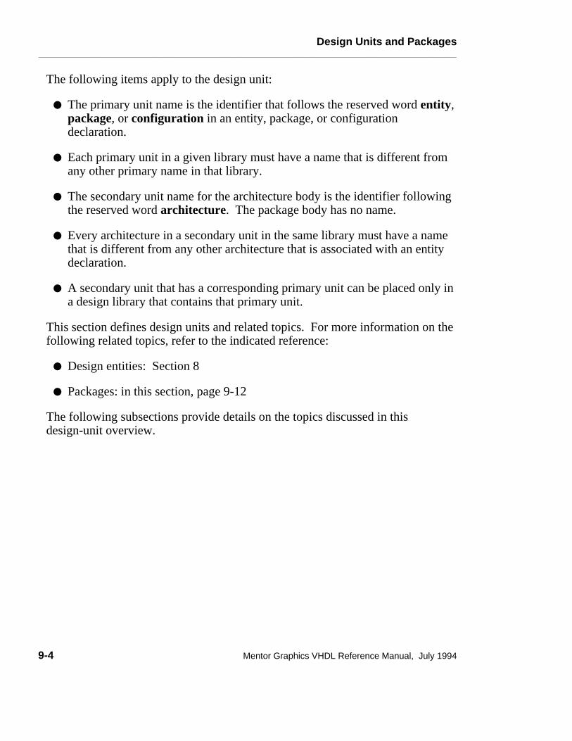
Design Units and Packages________________________________________________________________________________________________________________________
The following items apply to the design unit:
● The primary unit name is the identifier that follows the reserved word entity,package, or configuration in an entity, package, or configurationdeclaration.
● Each primary unit in a given library must have a name that is different fromany other primary name in that library.
● The secondary unit name for the architecture body is the identifier followingthe reserved word architecture. The package body has no name.
● Every architecture in a secondary unit in the same library must have a namethat is different from any other architecture that is associated with an entitydeclaration.
● A secondary unit that has a corresponding primary unit can be placed only ina design library that contains that primary unit.
This section defines design units and related topics. For more information on thefollowing related topics, refer to the indicated reference:
● Design entities: Section 8
● Packages: in this section, page 9-12
The following subsections provide details on the topics discussed in thisdesign-unit overview.
9-4 Mentor Graphics VHDL Reference Manual, July 1994

Design Units and Packages________________________________________________________________________________________________________________________
context_clauseContext clauses make design libraries and their contents visible to a design unit.Design libraries contain compiled library units that are available for use bydesign units. A design unit is analyzed within the environment specified by itscontext clauses.
Construct Placementdesign_unit
Syntax
context_clause ::= { context_item }
context_item ::= library_clause | use_clause
Definitions
■ library_clauseA library clause makes library units within a design library visible to adesign unit.
■ use_clause A use clause makes visible certain declarations within library units containedin a design library. The use clause is a shorthand method that relieves youfrom having to use a full selected name for declarations, if they exist in adesign library.
Mentor Graphics VHDL Reference Manual, July 1994 9-5

Design Units and Packages________________________________________________________________________________________________________________________
DescriptionS Figure 9-2 shows the context clause concept. The following list describes the
three situations (A,B, and C) shown in the figure.
A. In this situation, the design file contains a use clause to make the contents ofpackage "x" directly visible. This package is already visible by selection tothe design file environment.
B. In this situation, the design file contains a library clause to make library "a"and "b" visible. The library names within the design file are mapped to theoutside libraries with an implementation-dependent method. The physicallibraries then become visible to the current design file.
C. In this situation, the design file contains a library clause to make library "c"visible. A use clause is also in the context clause, which enables you to usethe shorthand method of making the items of library "c" directly visible. Thelibrary names within the design file are mapped to the outside libraries withan implementation-dependent method. Visibility is discussed in detail onpage 3-12.
For detailed information about the use clause, refer to page 3-22.
ExampleThe following example shows the context clause in a partial design file:
LIBRARY c ; USE c.ALL; -- context clause ENTITY tester IS PORT (pin1, pin2, pin3 : IN bit; pin4 : OUT bit); . . .
A VHDL implementation generates an implicit context clause for every designunit. This context clause consists of a library clause and a use clause, as thefollowing example shows:
LIBRARY std, work; USE std.standard.ALL;
The previous example shows that "std" is the library logical name for the designlibrary in which package "standard" is located. The use clause makes all thedeclarations in package "standard" directly visible. For more information on theworking library (work), refer to page 9-9.
9-6 Mentor Graphics VHDL Reference Manual, July 1994

Design Units and Packages________________________________________________________________________________________________________________________
���������������������������������������������
�����������������������������������
���������������������������������������������������������������
���������������������������������������������
USE x . ALL ;
PACKAGE x IS
LIBRARY a, b ;
LIBRARY c ;
USE c . ALL ;
Library a
Library b
Library cLogical-to-PhysicalMapping
Library a
Library b
Library c
A
B
Design Files
PhysicalLibraries
Logical-to-PhysicalMapping
C
Figure 9-2. Context Clause Concept
Mentor Graphics VHDL Reference Manual, July 1994 9-7

Design Units and Packages________________________________________________________________________________________________________________________
library_clauseA design library provides storage capability for compiled library or design unitsthat can be used in other hardware design descriptions. The library clausespecifies the logical names of libraries that the design unit can reference. Thelibrary clause is part of the context clause.
Construct Placementcontext_item, (context_clause, - design_unit)
Syntax
library_clause ::= library logical_name_list ;
logical_name_list ::= logical_name { , logical_name }
logical_name ::= identifier
DescriptionS The mapping of the logical name list in the library clause to the actual file
names occurs in the VHDL environment.
VHDL provides two classifications for design libraries:
● Working libraries
● Resource libraries
The working library is the library in which the compiled design unit is placed.The analogy to the working library is your working directory. When you compilethe design unit, it exists in the working directory in which you performed thecompilation. There is only one working library during the compilation of adesign unit.
The resource library is a library that contains the library units that the design unitbeing compiled references. There can be any number of resource libraries for agiven design unit. The working library itself can be a resource library.
Example
9-8 Mentor Graphics VHDL Reference Manual, July 1994
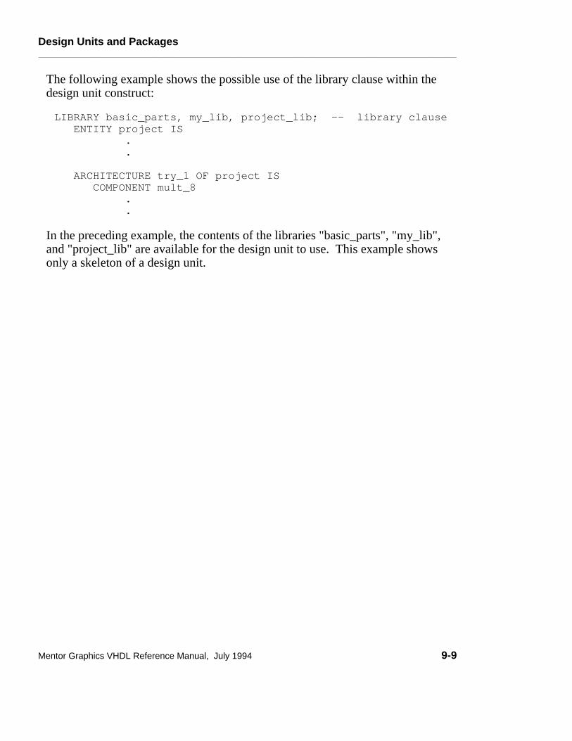
Design Units and Packages________________________________________________________________________________________________________________________
The following example shows the possible use of the library clause within thedesign unit construct:
LIBRARY basic_parts, my_lib, project_lib; -- library clause ENTITY project IS . .
ARCHITECTURE try_1 OF project IS COMPONENT mult_8 . .
In the preceding example, the contents of the libraries "basic_parts", "my_lib",and "project_lib" are available for the design unit to use. This example showsonly a skeleton of a design unit.
Mentor Graphics VHDL Reference Manual, July 1994 9-9

Design Units and Packages________________________________________________________________________________________________________________________
Example of a Design Library
The following example shows a design library containing one design unit. Thisdesign unit is a four input buffer with three control lines, as Figure 9-3 shows.
c2c3c1
a0a1
a2a3
q0q1
q2q3
N15
N20I3I4 I1
I2
74LS75
74LS75
74LS0074LS02
1_Q1QEN
1D 2Q2D 2_Q
1_Q1QEN
1D 2Q2D 2_Q
Figure 9-3. Input Buffer Schematic
The following code description shows a possible structural representation of theinput buffer in a design unit.
LIBRARY ls_lib, my_lib; -- context itemUSE ls_lib.ALL; -- context itemUSE my_lib.my_qsim_base.ALL; -- context itemENTITY alu_loader IS -- primary unitPORT(C1,C2,C3,A0,A1,A2,A3: IN my_qsim_12state; Q3,Q2,Q1,Q0: OUT my_qsim_12state);
BEGINEND alu_loader;
ARCHITECTURE struct OF alu_loader IS -- secondary unitCOMPONENT nand2 PORT (I0, I1 : IN my_qsim_12state;
OUT1 : OUT my_qsim_12state);END COMPONENT;COMPONENT nor2 PORT (I0, I1 : IN my_qsim_12state;
OUT1 : OUT my_qsim_12state);END COMPONENT;COMPONENT latch PORT ( EN, D1, D2 : IN my_qsim_12state;
9-10 Mentor Graphics VHDL Reference Manual, July 1994

Design Units and Packages________________________________________________________________________________________________________________________
Q1,Q_1,Q2,Q_2 : OUT my_qsim_12state);END COMPONENT;
FOR I1: latch USE ENTITY ls75;FOR I2: latch USE ENTITY ls75;FOR I3: nand2 USE ENTITY ls00;FOR I4: nor2 USE ENTITY ls02;
SIGNAL N15: my_qsim_12state;SIGNAL N20: my_qsim_12state;
BEGIN
I1: latch PORT MAP(EN => N20, D1 => A0, D2 => A1, Q1 => Q0, Q_1 => OPEN, Q2 => Q1, Q_2 => OPEN);
I2: latch PORT MAP(EN => N20, D1 => A2, D2 => A3, Q1 => Q2, Q_1 => OPEN, Q2 => Q3, Q_2 => OPEN);
I3: nand2 PORT MAP(I0 => C2, I1 => C3, OUT1 => N15);I4: nor2 PORT MAP(I0 => N15, I1 => C1, OUT1 => N20);
END struct;
Mentor Graphics VHDL Reference Manual, July 1994 9-11

Design Units and Packages________________________________________________________________________________________________________________________
PackagesPackages provide you with a location for collecting various commonly useddeclarations and subprograms. The items in a package are visible anywhere thename of the package is visible or where a use clause makes them visible. The useclause is discussed in detail on page 3-22.
Packages consist of two parts: a declaration and a body. This has the samebenefits as having separate declarations and bodies for entities and subprograms:
● One interface, the declaration, can have several different bodies.
● You can rewrite the bodies without having to recompile the declaration.
These features are all necessary for dividing up a project between teams. Figure9-4 shows the package concept.
Declarationsand
Subprograms
DescriptionCode
SharingOne Package
Package
Figure 9-4. Package Concept
9-12 Mentor Graphics VHDL Reference Manual, July 1994
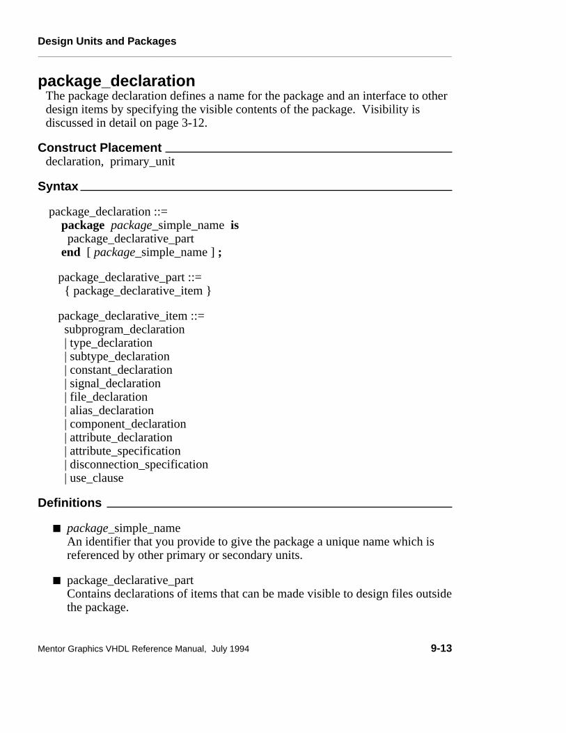
Design Units and Packages________________________________________________________________________________________________________________________
package_declarationThe package declaration defines a name for the package and an interface to otherdesign items by specifying the visible contents of the package. Visibility isdiscussed in detail on page 3-12.
Construct Placementdeclaration, primary_unit
Syntax
package_declaration ::= package package_simple_name is package_declarative_part end [ package_simple_name ] ;
package_declarative_part ::= { package_declarative_item }
package_declarative_item ::= subprogram_declaration | type_declaration | subtype_declaration | constant_declaration | signal_declaration | file_declaration | alias_declaration | component_declaration | attribute_declaration | attribute_specification | disconnection_specification | use_clause
Definitions
■ package_simple_nameAn identifier that you provide to give the package a unique name which isreferenced by other primary or secondary units.
■ package_declarative_partContains declarations of items that can be made visible to design files outsidethe package.
Mentor Graphics VHDL Reference Manual, July 1994 9-13
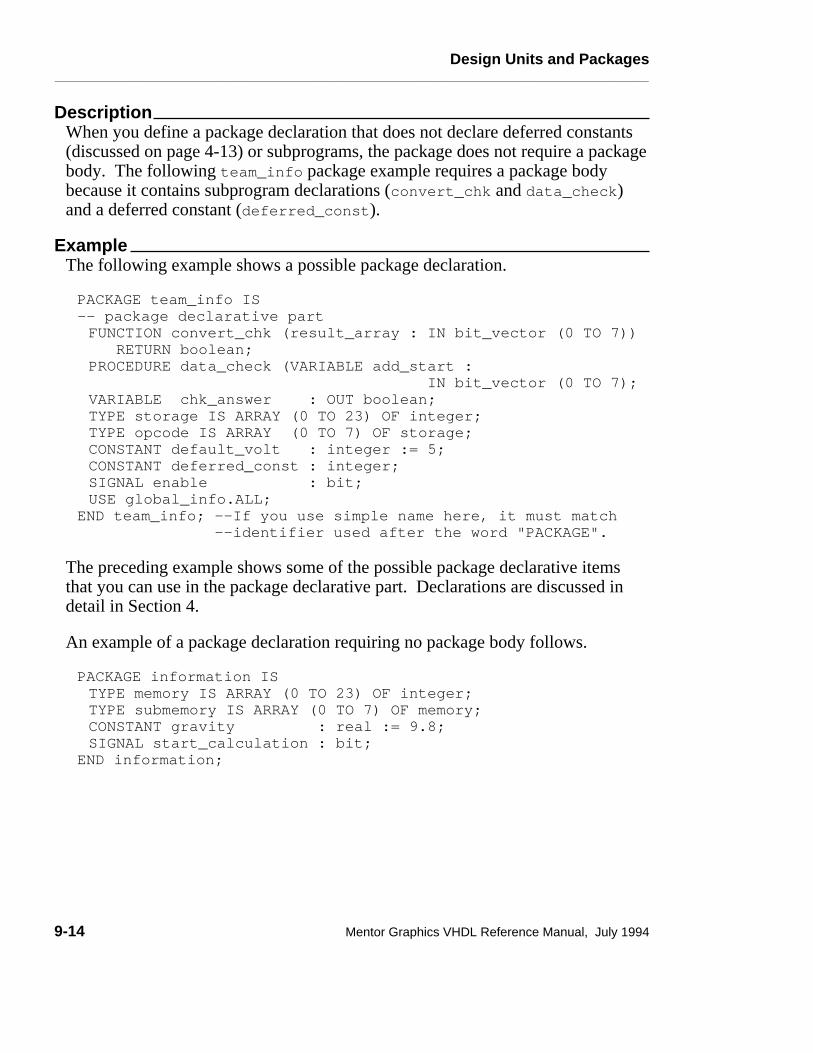
Design Units and Packages________________________________________________________________________________________________________________________
DescriptionWhen you define a package declaration that does not declare deferred constants(discussed on page 4-13) or subprograms, the package does not require a packagebody. The following team_info package example requires a package bodybecause it contains subprogram declarations (convert_chk and data_check)and a deferred constant (deferred_const).
ExampleThe following example shows a possible package declaration.
PACKAGE team_info IS-- package declarative part FUNCTION convert_chk (result_array : IN bit_vector (0 TO 7)) RETURN boolean; PROCEDURE data_check (VARIABLE add_start : IN bit_vector (0 TO 7);VARIABLE chk_answer : OUT boolean; TYPE storage IS ARRAY (0 TO 23) OF integer; TYPE opcode IS ARRAY (0 TO 7) OF storage;CONSTANT default_volt : integer := 5;CONSTANT deferred_const : integer; SIGNAL enable : bit;USE global_info.ALL;
END team_info; --If you use simple name here, it must match --identifier used after the word "PACKAGE".
The preceding example shows some of the possible package declarative itemsthat you can use in the package declarative part. Declarations are discussed indetail in Section 4.
An example of a package declaration requiring no package body follows.
PACKAGE information ISTYPE memory IS ARRAY (0 TO 23) OF integer;TYPE submemory IS ARRAY (0 TO 7) OF memory;CONSTANT gravity : real := 9.8;SIGNAL start_calculation : bit;
END information;
9-14 Mentor Graphics VHDL Reference Manual, July 1994
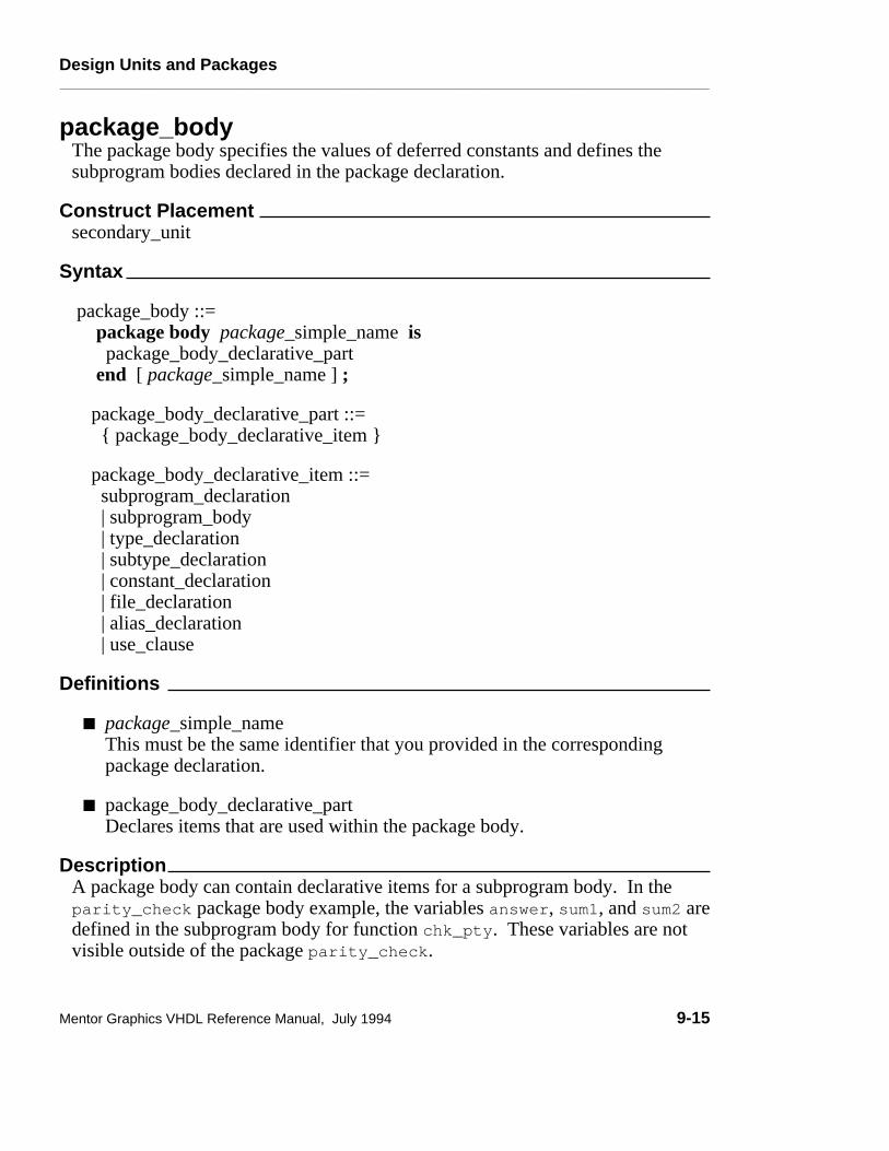
Design Units and Packages________________________________________________________________________________________________________________________
package_bodyThe package body specifies the values of deferred constants and defines thesubprogram bodies declared in the package declaration.
Construct Placementsecondary_unit
Syntax
package_body ::= package body package_simple_name is package_body_declarative_part end [ package_simple_name ] ;
package_body_declarative_part ::= { package_body_declarative_item }
package_body_declarative_item ::= subprogram_declaration | subprogram_body | type_declaration | subtype_declaration | constant_declaration | file_declaration | alias_declaration | use_clause
Definitions
■ package_simple_name This must be the same identifier that you provided in the correspondingpackage declaration.
■ package_body_declarative_partDeclares items that are used within the package body.
DescriptionA package body can contain declarative items for a subprogram body. In theparity_check package body example, the variables answer, sum1, and sum2 aredefined in the subprogram body for function chk_pty. These variables are notvisible outside of the package parity_check.
Mentor Graphics VHDL Reference Manual, July 1994 9-15

Design Units and Packages________________________________________________________________________________________________________________________
When you use deferred constants in your package declaration, the correspondingpackage must contain a constant declaration with a value for that deferredconstant. For more information on deferred constants, refer to page 4-13.
The value you assign to the deferred constant must be of the same type as definedin the package declaration. In the parity_check package body example, checkis a deferred constant whose value is resolved in the package body.
You can only use the name of the deferred constant in the default expression for alocal generic or port, or a formal parameter if this name is used before theconstant value is defined.
The VHDL standard predefines two packages for use in your designs. Thosepackages are package standard, which provides an assortment of commonpredefined functions, types, and subtypes, and package textio, which allows youto read from and write to formatted ASCII text files. Information on thesepackages is given in the in the following subsection, starting on page 9-18.
9-16 Mentor Graphics VHDL Reference Manual, July 1994

Design Units and Packages________________________________________________________________________________________________________________________
ExampleAn example of a package declaration with a package body follows:
-- Package declaration--PACKAGE parity_check IS FUNCTION chk_pty (ram_data_conc : IN bit_vector (0 TO 23); orig_data_conc: IN bit_vector (0 TO 23)) RETURN boolean;CONSTANT check : integer; --A deferred constant
END parity_check;
-- Package body
PACKAGE BODY parity_check ISCONSTANT check : integer := 0; --Deferred constantFUNCTION chk_pty (ram_data_conc : IN bit_vector (0 TO 23); orig_data_conc : IN bit_vector (0 TO 23)) RETURN boolean IS --subprogram body until "RETURN" VARIABLE answer : integer; --"answer" is not visible
--outside of this package VARIABLE sum1, sum2 : boolean := false; --"sum1" and "sum2"BEGIN --not visible outside this pack. FOR i IN 0 TO 17 LOOP
IF ram_data_conc(i) = ’1’ THEN sum1 := NOT sum1; -- compute parity for ram data END IF; IF orig_data_conc(i) = ’1’ THEN sum2 := NOT sum2; -- compute parity for opcode data END IF;
END LOOP; answer := check + 1; RETURN sum1 = sum2; -- return true if sum1 = sum2 END chk_pty;
END parity_check; --If you use package_simple_name, it must --match name used after "PACKAGE BODY"
Mentor Graphics VHDL Reference Manual, July 1994 9-17

Design Units and Packages________________________________________________________________________________________________________________________
Predefined PackagesPackage Standard
This subsection contains an annotated listing of VHDL package standard.Package "standard", which is a required part of all VHDL implementations,contains a number of useful predefined types, subtypes, and functions. You donot have to include explicit context clauses in your library units to make use ofitems declared in package standard. You cannot modify package standard.
������������������������������������ CAUTION
Do not use predefined type names for your own definitions. Whileit is possible to do so, it may become very confusing for you to keeptrack of when the system is using its definition of a predefined typeor is being overwritten to use your definition.
The following are the equivalent VHDL "headers" for package "standard":
PACKAGE standard IS
--predefined enumeration types:
TYPE bit IS (’0’, ’1’);
TYPE boolean IS (false, true);
9-18 Mentor Graphics VHDL Reference Manual, July 1994

Design Units and Packages________________________________________________________________________________________________________________________
TYPE character IS ( nul, soh, stx, etx, eot, enq, ack, bel, bs, ht, lf, vt, ff, cr, so, si, dle, dc1, dc2, dc3, dc4, nak, syn, etb, can, em, sub, esc, fsp, gsp, rsp, usp,
’ ’, ’!’, ’"’, ’#’, ’$’, ’%’, ’&’, ’’’, ’(’, ’)’, ’*’, ’+’, ’,’, ’-’, ’.’, ’/’, ’0’, ’1’, ’2’, ’3’, ’4’, ’5’, ’6’, ’7’, ’8’, ’9’, ’:’, ’;’, ’<’, ’=’, ’>’, ’?’,
’@’, ’A’, ’B’, ’C’, ’D’, ’E’, ’F’, ’G’, ’H’, ’I’, ’J’, ’K’, ’L’, ’M’, ’N’, ’O’, ’P’, ’Q’, ’R’, ’S’, ’T’, ’U’, ’V’, ’W’, ’X’, ’Y’, ’Z’, ’[’, ’\’, ’]’, ’^’, ’_’,
’‘’, ’a’, ’b’, ’c’, ’d’, ’e’, ’f’, ’g’, ’h’, ’i’, ’j’, ’k’, ’l’, ’m’, ’n’, ’o’, ’p’, ’q’, ’r’, ’s’, ’t’, ’u’, ’v’, ’w’, ’x’, ’y’, ’z’, ’{’ ’|’, ’}’, ’~’, DEL);
The ASCII mnemonics for file separator "fs", group separator "gs", recordseparator "rs", and unit separator "us" are represented by fsp, gsp, rsp, and usp,respectively, in type character in order to avoid conflict with the units of typetime.
TYPE severity_level IS (note, warning, error, failure);
-- predefined numeric types:
TYPE integer IS RANGE -2147483648 TO 2147483647; TYPE real IS RANGE -1.79769E308 TO 1.79769E308;
The ranges for types integer and real are machine-dependent. The valuesshown in the previous type definitions assume a 32-bit, two’s complementmachine that follows IEEE double-precision standard.
Mentor Graphics VHDL Reference Manual, July 1994 9-19

Design Units and Packages________________________________________________________________________________________________________________________
SE
-- predefined type time;
TYPE time IS RANGE -a_number TO +a_number UNITS -- a_number is machine-dependentfs; -- femtosecondsps = 1000 fs; -- picosecondsns = 1000 ps; -- nanosecondsus = 1000 ns; -- microsecondsms = 1000 us; -- millisecondssec = 1000 ms; -- secondsmin = 60 sec; -- minuteshr = 60 min; -- hoursEND UNITS
-- function that returns the current simulator time;
FUNCTION now RETURN time;
-- predefined numeric subtypes:
SUBTYPE natural IS integer RANGE 0 TO integer’high;SUBTYPE positive IS integer RANGE 1 TO integer’high;
-- predefined array types
TYPE string IS ARRAY (positive RANGE <>) OF character;TYPE bit_vector IS ARRAY (natural RANGE <>) OF bit;
END standard;
9-20 Mentor Graphics VHDL Reference Manual, July 1994

Design Units and Packages________________________________________________________________________________________________________________________
std_logic_1164S Package "std_logic_1164" and the related extensions package containsdeclarations of types and subprograms that support a standard nine-state logicsystem. These packages are located in the "ieee" library. The "std_logic_1164"package has been developed by the IEEE Design Automation StandardsSubcommittee (Modeling group).
-- ------------------------------------------------------------ Title : std_logic_1164 multi-value logic system-- Library : This package shall be compiled into a library -- : symbolically named IEEE.-- : -- Developers: IEEE model standards group (par 1164)-- Purpose : This packages defines a standard for designers-- : to use in describing the interconnection data -- : types used in vhdl modeling.-- : -- Limitation: The logic system defined in this package may-- : be insufficient for modeling switched -- : transistors, since such a requirement is out of -- : the scope of this effort. Furthermore, -- : mathematics, primitives, timing standards, etc. -- : are considered orthogonal issues as it relates to-- : this package and are therefore beyond the scope -- : of this effort.-- Note : No declarations or definitions shall be included -- : in, or excluded from this package. The "package -- : declaration" defines the types, subtypes and -- : declarations of std_logic_1164. The -- : std_logic_1164 package body shall be considered-- : the formal definition of the semantics of this -- : package. Tool developers may choose to implement -- : the package body in the most efficient manner -- : available to them.-- ------------------------------------------------------------ modification history :---- version | mod. date:| -- v4.200 | 01/02/92 |
-- -----------------------------------------------------------
Mentor Graphics VHDL Reference Manual, July 1994 9-21

Design Units and Packages________________________________________________________________________________________________________________________
PACKAGE std_logic_1164 IS
-- logic state system (unresolved)
TYPE std_ulogic IS ( ’U’, -- Uninitialized ’X’, -- Forcing Unknown ’0’, -- Forcing 0 ’1’, -- Forcing 1 ’Z’, -- High Impedance ’W’, -- Weak Unknown ’L’, -- Weak 0 ’H’, -- Weak 1 ’-’ -- Don’t care ); -------------------------------------------------------------- -- unconstrained array of std_ulogic for use with the -- resolution function TYPE std_ulogic_vector IS ARRAY(NATURAL RANGE <>) OF std_ulogic;
--------------------------------------------------------------- -- resolution function FUNCTION resolved (s: std_ulogic_vector ) RETURN std_ulogic;
--------------------------------------------------------------- -- *** industry standard logic type ***
SUBTYPE std_logic IS resolved std_ulogic;
--------------------------------------------------------------- -- unconstrained array of std_logic for use in declaring -- signal arrays TYPE std_logic_vector IS ARRAY (NATURAL RANGE <>) OF std_logic;
--------------------------------------------------------------- -- common subtypes SUBTYPE X01 IS resolved std_ulogic RANGE ’X’ TO ’1’; -- (’X’,’0’,’1’) SUBTYPE X01Z IS resolved std_ulogic RANGE ’X’ TO ’Z’; -- (’X’,’0’,’1’,’Z’) SUBTYPE UX01 IS resolved std_ulogic RANGE ’U’ TO ’1’; -- (’U’,’X’,’0’,’1’) SUBTYPE UX01Z IS resolved std_ulogic RANGE ’U’ TO ’Z’; -- (’U’,’X’,’0’,’1’,’Z’)
9-22 Mentor Graphics VHDL Reference Manual, July 1994

Design Units and Packages________________________________________________________________________________________________________________________
----------------------------------------------------------- -- overloaded logical operators FUNCTION "and" ( l: std_ulogic; r: std_ulogic ) RETURN UX01; FUNCTION "nand" ( l: std_ulogic; r: std_ulogic ) RETURN UX01; FUNCTION "or" ( l: std_ulogic; r: std_ulogic ) RETURN UX01; FUNCTION "nor" ( l: std_ulogic; r: std_ulogic ) RETURN UX01; FUNCTION "xor" ( l: std_ulogic; r: std_ulogic ) RETURN UX01;-- function "xnor" (l: std_ulogic; r: std_ulogic ) return ux01; FUNCTION "not" ( l : std_ulogic ) RETURN UX01;
--------------------------------------------------------------- -- vectorized overloaded logical operators FUNCTION "and" (l, r: std_logic_vector ) RETURN std_logic_vector; FUNCTION "and" (l, r: std_ulogic_vector ) RETURN std_ulogic_vector;
FUNCTION "nand" (l, r: std_logic_vector ) RETURN std_logic_vector; FUNCTION "nand" (l, r: std_ulogic_vector ) RETURN std_ulogic_vector;
FUNCTION "or" (l, r: std_logic_vector ) RETURN std_logic_vector; FUNCTION "or" (l, r: std_ulogic_vector ) RETURN std_ulogic_vector;
FUNCTION "nor" (l, r: std_logic_vector ) RETURN std_logic_vector; FUNCTION "nor" (l, r: std_ulogic_vector ) RETURN std_ulogic_vector;
FUNCTION "xor" (l, r: std_logic_vector ) RETURN std_logic_vector; FUNCTION "xor" (l, r: std_ulogic_vector) RETURN std_ulogic_vector;
---------------------------------------------------------------- Note: The declaration and implementation of the "xnor" -- function is specifically commented until at which time the -- VHDL language has been officially adopted as containing such-- a function. At such a point, the following comments may be -- removed along with this notice without further "official" -- ballotting of this std_logic_1164 package. -- It is the intent of this effort to provide such a function -- once it becomes available in the VHDL standard.---------------------------------------------------------------
Mentor Graphics VHDL Reference Manual, July 1994 9-23

Design Units and Packages________________________________________________________________________________________________________________________
-- function "xnor" ( l, r : std_logic_vector ) -- return std_logic_vector;-- function "xnor" ( l, r : std_ulogic_vector ) -- return std_ulogic_vector;
FUNCTION "not" (l: std_logic_vector ) RETURN std_logic_vector; FUNCTION "not" (l: std_ulogic_vector) RETURN std_ulogic_vector;
--------------------------------------------------------------- -- conversion functions FUNCTION To_bit (s: std_ulogic; xmap : BIT := ’0’) RETURN BIT; FUNCTION To_bitvector (s: std_logic_vector ; xmap : BIT := ’0’) RETURN BIT_VECTOR; FUNCTION To_bitvector (s: std_ulogic_vector; xmap : BIT := ’0’) RETURN BIT_VECTOR; FUNCTION To_StdULogic (b: BIT ) RETURN std_ulogic; FUNCTION To_StdLogicVector (b: BIT_VECTOR) RETURN std_logic_vector; FUNCTION To_StdLogicVector (s: std_ulogic_vector ) RETURN std_logic_vector; FUNCTION To_StdULogicVector (b: BIT_VECTOR ) RETURN std_ulogic_vector; FUNCTION To_StdULogicVector (s: std_logic_vector ) RETURN std_ulogic_vector
-------------------------------------------------------------- -- strength strippers and type convertors FUNCTION To_X01 (s: std_logic_vector ) RETURN std_logic_vector; FUNCTION To_X01 (s: std_ulogic_vector ) RETURN std_ulogic_vector; FUNCTION To_X01 (s: std_ulogic ) RETURN X01; FUNCTION To_X01 (b: BIT_VECTOR ) RETURN std_logic_vector; FUNCTION To_X01 (b: BIT_VECTOR ) RETURN std_ulogic_vector; FUNCTION To_X01 (b: BIT ) RETURN X01;
FUNCTION To_X01Z (s: std_logic_vector) RETURN std_logic_vector; FUNCTION To_X01Z (s:std_ulogic_vector) RETURN std_ulogic_vector; FUNCTION To_X01Z (s: std_ulogic ) RETURN X01Z; FUNCTION To_X01Z (b: BIT_VECTOR ) RETURN std_logic_vector; FUNCTION To_X01Z (b: BIT_VECTOR ) RETURN std_ulogic_vector; FUNCTION To_X01Z (b: BIT ) RETURN X01Z; FUNCTION To_UX01 (s: std_logic_vector) RETURN std_logic_vector;
9-24 Mentor Graphics VHDL Reference Manual, July 1994

Design Units and Packages________________________________________________________________________________________________________________________
FUNCTION To_UX01 (s: std_ulogic_vector) RETURN std_ulogic_vector; FUNCTION To_UX01 (s: std_ulogic ) RETURN UX01; FUNCTION To_UX01 (b: BIT_VECTOR ) RETURN std_logic_vector; FUNCTION To_UX01 (b: BIT_VECTOR ) RETURN std_ulogic_vector; FUNCTION To_UX01 (b: BIT ) RETURN UX01;--------------------------------------------------------------- -- edge detection FUNCTION rising_edge (SIGNAL s : std_ulogic) RETURN BOOLEAN; FUNCTION falling_edge (SIGNAL s : std_ulogic) RETURN BOOLEAN;
--------------------------------------------------------------- -- object contains an unknown FUNCTION Is_X ( s : std_ulogic_vector ) RETURN BOOLEAN; FUNCTION Is_X ( s : std_logic_vector ) RETURN BOOLEAN; FUNCTION Is_X ( s : std_ulogic ) RETURN BOOLEAN;
END std_logic_1164;
Mentor Graphics VHDL Reference Manual, July 1994 9-25

Design Units and Packages________________________________________________________________________________________________________________________
std_logic_1164_extS The IEEE 1164 extensions package contains declarations of types and subprograms that support a standard nine-state logic system. This package islocated in the "ieee" library.
-- ------------------------------------------------------------- File name : std_logic_1164_ext_header.pkg.vhdl-- Title : STD_LOGIC_1164_EXTENSIONS package -- : ( multivalue logic system )-- Library : -- Author(s) : MENTOR GRAPHICS CORPORATION.-- Purpose : This packages defines a standard for digital -- : designers to use in describing the-- : interconnection data types used in modeling-- : common ttl, cmos, GaAs, nmos, pmos, and ecl -- : digital devices. -- :-- Notes : The logic system defined in this package may-- : be insufficient for modeling switched-- : transistors, since that requirement is out of -- : the scope of this effort.-- :-- : No other declarations or definitions shall be -- : included in this package. Any additional -- : declarations shall be placed in other orthogonal-- : packages ( ie. timing, etc )
-- -------------------------------------------------------------- Modification History :-- ------------------------------------------------------------- Version No:| Author:| Mod. Date:| Changes Made:-- v1.00 | kk | 05/26/91 | functions/types used as -- extensions to support-- synthesis.-- ------------------------------------------------------------LIBRARY IEEE;
PACKAGE std_logic_1164_extensions IS USE ieee.std_logic_1164.ALL;
------------------------------------------------------------ -- FUNCTIONS AND TYPES DECLARED FOR SYNTHESIS
-- Resolution function and resolved subtype for STD_ULOGIC: FUNCTION std_ulogic_wired_x (input : std_ulogic_vector)
9-26 Mentor Graphics VHDL Reference Manual, July 1994

Design Units and Packages________________________________________________________________________________________________________________________
RETURN std_ulogic; -- a wired ’X’ operation is performed on the inputs to -- determine the resolved value FUNCTION std_ulogic_wired_or (input : std_ulogic_vector) RETURN std_ulogic; -- a wired OR operation is performed on the inputs to -- determine the resolved value FUNCTION std_ulogic_wired_and (input : std_ulogic_vector) RETURN std_ulogic; -- a wired AND operation is performed on the inputs to -- determine the resolved value SUBTYPE std_ulogic_resolved_x IS std_ulogic_wired_x std_ulogic; TYPE std_ulogic_resolved_x_vector IS ARRAY(NATURAL RANGE <>) OF std_ulogic_resolved_x; SUBTYPE std_ulogic_resolved_or IS std_ulogic_wired_or std_ulogic; TYPE std_ulogic_resolved_or_vector IS ARRAY(NATURAL RANGE <>) OF std_ulogic_resolved_or; SUBTYPE std_ulogic_resolved_and IS std_ulogic_wired_and std_ulogic; TYPE std_ulogic_resolved_and_vector IS ARRAY(NATURAL RANGE <>) OF std_ulogic_resolved_and; ------------------------------------------------------------ -- Overloaded Logical Operators -- FUNCTION "and" ( l, r : std_ulogic ) RETURN std_ulogic;-- FUNCTION "nand" ( l, r : std_ulogic ) RETURN std_ulogic;-- FUNCTION "or" ( l, r : std_ulogic ) RETURN std_ulogic;-- FUNCTION "nor" ( l, r : std_ulogic ) RETURN std_ulogic;-- FUNCTION "xor" ( l, r : std_ulogic ) RETURN std_ulogic;-- FUNCTION "not" ( l : std_ulogic ) RETURN std_ulogic;
------------------------------------------------------------
Mentor Graphics VHDL Reference Manual, July 1994 9-27

Design Units and Packages________________________________________________________________________________________________________________________
-- Vectorized Overloaded Logical Operators -- FUNCTION "and" (l, r: std_ulogic_vector ) -- RETURN std_ulogic_vector;-- FUNCTION "nand"(l, r: std_ulogic_vector ) -- RETURN std_ulogic_vector;-- FUNCTION "or" (l, r: std_ulogic_vector ) -- RETURN std_ulogic_vector;-- FUNCTION "nor" (l, r: std_ulogic_vector ) -- RETURN std_ulogic_vector;-- FUNCTION "xor" (l, r: std_ulogic_vector ) -- RETURN std_ulogic_vector;-- FUNCTION "not" (l : std_ulogic_vector ) -- RETURN std_ulogic_vector;
------------------------------------------------------------ -- Overloaded Relational Operators FUNCTION "=" ( l, r : std_ulogic ) RETURN std_ulogic; FUNCTION "/=" ( l, r : std_ulogic ) RETURN std_ulogic; FUNCTION "<" ( l, r : std_ulogic ) RETURN std_ulogic; FUNCTION ">" ( l, r : std_ulogic ) RETURN std_ulogic; FUNCTION "<=" ( l, r : std_ulogic ) RETURN std_ulogic; FUNCTION ">=" ( l, r : std_ulogic ) RETURN std_ulogic;
FUNCTION "=" ( l, r : std_ulogic ) RETURN boolean; FUNCTION "/=" ( l, r : std_ulogic ) RETURN boolean; FUNCTION "<" ( l, r : std_ulogic ) RETURN boolean; FUNCTION ">" ( l, r : std_ulogic ) RETURN boolean; FUNCTION "<=" ( l, r : std_ulogic ) RETURN boolean; FUNCTION ">=" ( l, r : std_ulogic ) RETURN boolean;
------------------------------------------------------------ -- Vectorized Overloaded Relational Operators FUNCTION "=" ( l, r : std_ulogic_vector ) RETURN std_ulogic; FUNCTION "/=" ( l, r : std_ulogic_vector ) RETURN std_ulogic; FUNCTION "<" ( l, r : std_ulogic_vector ) RETURN std_ulogic; FUNCTION ">" ( l, r : std_ulogic_vector ) RETURN std_ulogic; FUNCTION "<=" ( l, r : std_ulogic_vector ) RETURN std_ulogic; FUNCTION ">=" ( l, r : std_ulogic_vector ) RETURN std_ulogic;
FUNCTION "=" ( l, r : std_ulogic_vector ) RETURN boolean; FUNCTION "/=" ( l, r : std_ulogic_vector ) RETURN boolean; FUNCTION "<" ( l, r : std_ulogic_vector ) RETURN boolean; FUNCTION ">" ( l, r : std_ulogic_vector ) RETURN boolean; FUNCTION "<=" ( l, r : std_ulogic_vector ) RETURN boolean; FUNCTION ">=" ( l, r : std_ulogic_vector ) RETURN boolean;
------------------------------------------------------------
9-28 Mentor Graphics VHDL Reference Manual, July 1994

Design Units and Packages________________________________________________________________________________________________________________________
-- Overloaded "+" and "-" Operators FUNCTION "+" ( l, r : std_ulogic ) RETURN std_ulogic; FUNCTION "-" ( l, r : std_ulogic ) RETURN std_ulogic;
------------------------------------------------------------ -- Vectorized Overloaded Arithmetic Operators FUNCTION "+"(l,r: std_ulogic_vector) RETURN std_ulogic_vector; FUNCTION "-"(l,r: std_ulogic_vector) RETURN std_ulogic_vector; FUNCTION "*"(l,r: std_ulogic_vector) RETURN std_ulogic_vector; FUNCTION "/"(l,r: std_ulogic_vector) RETURN std_ulogic_vector; FUNCTION "MOD" (l,r: std_ulogic_vector) RETURN std_ulogic_vector; FUNCTION "REM" (l,r: std_ulogic_vector) RETURN std_ulogic_vector; FUNCTION "**" (l,r: std_ulogic_vector) RETURN std_ulogic_vector;
------------------------------------------------------------ -- Conversion Functions -------------------------------------------------------------- FUNCTION Convert_to_Bit (val: std_ulogic_vector )-- RETURN bit_vector; FUNCTION Convert_to_Integer(val: std_ulogic_vector; x: integer := 0) RETURN integer;
FUNCTION Convert_to_Std_ulogic (val: integer; size: integer ) RETURN std_ulogic_vector; FUNCTION Convert_to_Std_ulogic (val: bit_vector ) RETURN std_ulogic_vector; FUNCTION Convert_to_Std_ulogic (val: bit ) RETURN std_ulogic;
END std_logic_1164_extensions;
Mentor Graphics VHDL Reference Manual, July 1994 9-29
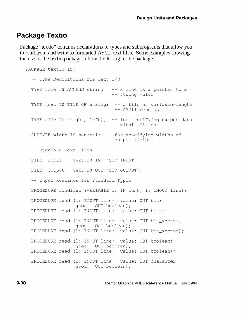
Design Units and Packages________________________________________________________________________________________________________________________
Package Textio
Package "textio" contains declarations of types and subprograms that allow youto read from and write to formatted ASCII text files. Some examples showingthe use of the textio package follow the listing of the package.
PACKAGE textio IS: -- Type Definitions for Text I/O TYPE line IS ACCESS string; -- a line is a pointer to a -- string value TYPE text IS FILE OF string; -- a file of variable-length -- ASCII records TYPE side IS (right, left); -- for justifying output data -- within fields SUBTYPE width IS natural; -- for specifying widths of -- output fields -- Standard Text Files FILE input: text IS IN "STD_INPUT"; FILE output: text IS OUT "STD_OUTPUT"; -- Input Routines for Standard Types PROCEDURE readline (VARIABLE f: IN text; l: INOUT line); PROCEDURE read (l: INOUT line; value: OUT bit; good: OUT boolean); PROCEDURE read (l: INOUT line; value: OUT bit); PROCEDURE read (l: INOUT line; value: OUT bit_vector; good: OUT boolean); PROCEDURE read (l: INOUT line; value: OUT bit_vector); PROCEDURE read (l: INOUT line; value: OUT boolean; good: OUT boolean); PROCEDURE read (l: INOUT line; value: OUT boolean); PROCEDURE read (l: INOUT line; value: OUT character; good: OUT boolean);
9-30 Mentor Graphics VHDL Reference Manual, July 1994

Design Units and Packages________________________________________________________________________________________________________________________
PROCEDURE read (l: INOUT line; value: OUT character); PROCEDURE read (l: INOUT line; value: OUT integer ; good: OUT boolean); PROCEDURE read (l: INOUT line; value: OUT integer); PROCEDURE read (l: INOUT line; value: OUT real; good: OUT boolean); PROCEDURE read (l: INOUT line; value: OUT real); PROCEDURE read (l: INOUT line; value: OUT string; good: OUT boolean); PROCEDURE read (l: INOUT line; value: OUT string); PROCEDURE read (l: INOUT line; value: OUT time; good: OUT boolean); PROCEDURE read (l: INOUT line; value: OUT time); -- Output Routines for Standard Types PROCEDURE writeline (f: OUT text; l: INOUT line); PROCEDURE write (l: INOUT line; value: IN bit; justified: IN side:= right; field: IN width := 0); PROCEDURE write (l: INOUT line; value: IN bit_vector; justified: IN side:= right; field: IN width := 0); PROCEDURE write (l: INOUT line; value: IN boolean; justified: IN side:= right; field: IN width := 0); PROCEDURE write (l: INOUT line; value: IN character; justified: IN side:= right; field: IN width := 0); PROCEDURE write (l: INOUT line; value: IN integer; justified: IN side:= right; field: IN width := 0); PROCEDURE write (l: INOUT line; value: IN real; justified: IN side:= right; field: IN width := 0; digits: IN natural:= 0); PROCEDURE write (l: INOUT line; value: IN string; justified: IN side:= right; field: IN width := 0); PROCEDURE write (l: INOUT line; value: IN time; justified: IN side:= right; field: IN width := 0; unit: IN time:= ns);
Mentor Graphics VHDL Reference Manual, July 1994 9-31

Design Units and Packages________________________________________________________________________________________________________________________
-- File Position Predicates FUNCTION endfile (f: IN text) RETURN boolean; END textio;
The following example writes two characters, "H" and "I", on separate lines, to afile named txtio_tmp.
USE std.textio.ALL;
ENTITY textio_ex ISBEGINEND textio_ex ;
ARCHITECTURE behav OF textio_ex IS
FILE out1: text IS OUT "txtio_tmp";
BEGIN
PROCESS
VARIABLE line1 : line; VARIABLE char1 : character; BEGIN
char1 := ’H’; write(line1,char1,RIGHT,0); char1 := ’I’; write(line1,char1,RIGHT,0); writeline(out1,line1); WAIT;
END PROCESS;
END behav;
9-32 Mentor Graphics VHDL Reference Manual, July 1994

Design Units and Packages________________________________________________________________________________________________________________________
Mentor Graphics Predefined Packages
Mentor Graphics has created packages that define various types and subprogramsthat make it possible to write and simulate a VHDL model within the MentorGraphics environment. These packages are written in standard VHDL and can becompiled on any system that supports the language.
E Of the packages that Mentor Graphics supplies, one package called "math" is located in the "std" library along with the "standard" and "textio" packages. Themath package contains the set of ANSI C math functions and constants.
Other Mentor Graphics supplied packages are located in a library called"mgc_portable". These packages are as follows:
● "qsim_logic" The package qsim_logic contains basic 4-state and 12-statetypes along with supporting resolution, conversion, and operator functions.
● "qsim_relations" The package qsim_relations defines all relational operatorsfor qsim_state that return boolean, to deal with unknown states (’X’)reasonably. Also defined are relational operators for bit_vector that donumerical comparisons by zero-extending shorter operands.
The "headers" for the Mentor Graphics predefined packages have been providedin the following subsections. The package bodies are available from MentorGraphics.
Mentor Graphics VHDL Reference Manual, July 1994 9-33

Design Units and Packages________________________________________________________________________________________________________________________
std.math
--These functions and procedures provide access to system --supplied math functions. As such, they are not guaranteed --portable or even available between different hosts. In --other words, different host platforms may produce different --results under the same circumstances. Mentor Graphics is --not responsible for the availability or performance of these --functions. For a description of how these functions work, --please refer to the ANSI C Language Reference Manual.
PACKAGE math IS
SUBTYPE natural_real IS real RANGE 0.0 TO real’high
--NOTE: The precision of these constants is specified-- greater than the host implementation is capable of -- representing. REAL’s are only accurate to -- approximately 16 decimal digits.
CONSTANT e : real := 2.7182818284590452354 CONSTANT log2e : real := 1.4426950408889634074 CONSTANT log10e : real := 0.43429448190325182765 CONSTANT ln2 : real := 0.69314718055994530942 CONSTANT ln10 : real := 2.30258509299404568402 CONSTANT pi : real := 3.14159265358979323846
-- e^x FUNCTION exp( x : real ) RETURN real;
-- natural logarithm FUNCTION log( x : natural_real ) RETURN real;
-- logarithm base 10 FUNCTION log10( x : natural_real ) RETURN real;
-- square root FUNCTION sqrt( x : natural_real ) RETURN real;
-- X*2^n FUNCTION ldexp( x : real; n : integer ) RETURN real;
-- X^Y -- if x is negative then y must be a whole number. FUNCTION pow( X, Y : real ) RETURN real;
--remainder of x/y
9-34 Mentor Graphics VHDL Reference Manual, July 1994

Design Units and Packages________________________________________________________________________________________________________________________
--returns the value x - i * y, for some integer i such --that, if y is nonzero, the result has the same sign as x --and magnitude less than the magnitude of y. Y should not --be zero. FUNCTION fmod( x, y : real ) RETURN real;
-- largest integer -- returns the largest integer not greater than x FUNCTION floor( x : real ) RETURN real;
-- smallest integer -- returns the smallest integer not less than x FUNCTION ceil( x : real ) RETURN real;
-- hyperbolic functions FUNCTION sinh( x : real ) RETURN real; FUNCTION cosh( x : real ) RETURN real; FUNCTION tanh( x : real ) RETURN real;
-- trigonometric functions FUNCTIONS sin( x : real ) RETURN real; FUNCTIONS cos( x : real ) RETURN real; FUNCTIONS tan( x : real ) RETURN real; FUNCTIONS asin( x : real ) RETURN real; FUNCTIONS acos( x : real ) RETURN real; FUNCTIONS atan( x : real ) RETURN real; FUNCTIONS atan2( x, y : real ) RETURN real;
-- pseudo-random numbers -- should be used as follows: -- -- VARIABLE rn : real; -- . . . -- rn := .1459; -- . . . -- rn := rand( rn ); -- -- -- rn is the random number -- --Generate random number from seed --returns a number between [0.0, 1.0) based on the seed. --The results from this function is not guaranteed to be --portable. FUNCTION rand( seed : real ) RETURN real;END math;
Mentor Graphics VHDL Reference Manual, July 1994 9-35

Design Units and Packages________________________________________________________________________________________________________________________
mgc_portable.qsim_logic
SPACKAGE qsim_logic IS
This predefined Mentor Graphics package provides enumerated types that allowthe designer to interface from a VHDL model to a Mentor Graphics model orallow a VHDL model to be used in a non-VHDL design.
The qsim_state type provides signal values that are typically found in mostsimulators, with minimum worry about signal strengths. The signal is mapped asfollows: -- Mentor maps to STATE -- ------------------------- -- 0S, 0r => 0 -- 1S, 1r => 1 -- XS, Xr, Xi => X -- 0i, 1i => X -- 0Z, Xz, 1Z => Z -- STATE maps to Mentor -- -------------------------- -- 0 => 0S -- 1 => 1S -- X => XS -- Z => XZ
TYPE qsim_state IS (’X’, ’0’, ’1’, ’Z’); TYPE qsim_state_vector IS ARRAY (natural RANGE <>) OF qsim_state;
-- Resolution function and resolved subtype for qsim_state: FUNCTION qsim_wired_x (input : qsim_state_vector) RETURN qsim_state; --A wired ’X’ operation is performed on the inputs to --determine the resolved value as follows: -- X 0 1 Z -- X ’X’,’X’,’X’,’X’ -- 0 ’X’,’0’,’X’,’0’ -- 1 ’X’,’X’,’1’,’1’ -- Z ’X’,’0’,’1’,’Z’
9-36 Mentor Graphics VHDL Reference Manual, July 1994

Design Units and Packages________________________________________________________________________________________________________________________
FUNCTION qsim_wired_or (input: qsim_state_vector) RETURN qsim_state; --A wired OR operation is performed on the inputs to --determine the resolved value as follows: -- X 0 1 Z -- X ’X’,’X’,’1’,’X’ -- 0 ’X’,’0’,’1’,’0’ -- 1 ’1’,’1’,’1’,’1’ -- Z ’X’,’0’,’1’,’Z’
FUNCTION qsim_wired_and (input: qsim_state_vector) RETURN qsim_state; --A wired AND operation is performed on the inputs to --determine the resolved value as follows: -- X 0 1 Z -- X ’X’,’0’,’X’,’X’ -- 0 ’0’,’0’,’0’,’0’ -- 1 ’X’,’0’,’1’,’1’ -- Z ’X’,’0’,’1’,’Z’
SUBTYPE qsim_state_resolved_x IS qsim_wired_x qsim_state; TYPE qsim_state_resolved_x_vector IS ARRAY(natural RANGE <>) OF qsim_state_resolved_x;
SUBTYPE qsim_state_resolved_or IS qsim_wired_or qsim_state; TYPE qsim_state_resolved_or_vector IS ARRAY(natural RANGE <>) OF qsim_state_resolved_or;
SUBTYPE qsim_state_resolved_and IS qsim_wired_and qsim_state; TYPE qsim_state_resolved_and_vector IS ARRAY(natural RANGE <>) OF qsim_state_resolved_and;
The qsim_12state values and strengths map one-for-one with QuickSim II. Thishas an implicit resolution function that matches QuickSim II. The qsim_12stateand the qsim_12state_vector types are provided for accessing all stateinformation and for interfacing to other Mentor Graphics primitives. Onlyconversion functions to and from are provided.
TYPE qsim_12state IS ( SXR, SXZ, SXS, SXI, S0R, S0Z, S0S, S0I, S1R, S1Z, S1S, S1I );
--Now a vector for qsim_12state: TYPE qsim_12state_vector IS ARRAY (natural RANGE <>) OF qsim_12state;
Mentor Graphics VHDL Reference Manual, July 1994 9-37

Design Units and Packages________________________________________________________________________________________________________________________
--Resolution function and resolved subtype for qsim_12state: FUNCTION qsim_12state_wired (input : qsim_12state_vector) RETURN qsim_12state; --This resolution function implements QuickSim’s --resolution function as follows: -- SXR SXZ SXS SXI S0R S0Z S0S S0I S1R S1Z S1S S1I -- ----------------------------------------------- -- SXR | SXR SXR SXS SXI SXR SXR S0S SXI SXR SXR S1S SXI -- SXZ | SXR SXZ SXS SXI S0R SXZ S0S SXI S1R SXZ S1S SXI -- SXS | SXS SXS SXS SXS SXS SXS SXS SXS SXS SXS SXS SXS -- SXI | SXI SXI SXS SXI SXI SXI SXS SXI SXI SXI SXS SXI -- S0R | SXR S0R SXS SXI S0R S0R S0S S0I SXR S0R S1S SXI -- S0Z | SXR SXZ SXS SXI S0R S0Z S0S S0I S1R SXZ S1S SXI -- S0S | S0S S0S SXS SXS S0S S0S S0S S0S S0S S0S SXS SXS -- S0I | SXI SXI SXS SXI S0I S0I S0S S0I SXI SXI SXS SXI -- S1R | SXR S1R SXS SXI SXR S1R S0S SXI S1R S1R S1S S1I -- S1Z | SXR SXZ SXS SXI S0R SXZ S0S SXI S1R S1Z S1S S1I -- S1S | S1S S1S SXS SXS S1S S1S SXS SXS S1S S1S S1S S1S -- S1I | SXI SXI SXS SXI SXI SXI SXS SXI S1I S1I S1S S1I
SUBTYPE qsim_12state_resolved IS qsim_wired qsim_12state; TYPE qsim_12state_resolved_vector IS ARRAY(natural RANGE <>) OF qsim_12state_resolved;
--Other miscellaneous types related to qsim_12state. SUBTYPE qsim_value IS qsim_state RANGE ’X’ TO ’1’; TYPE qsim_value_vector IS ARRAY (natural RANGE <>) OF qsim_value; TYPE qsim_strength IS (’I’, ’Z’, ’R’, ’S’); TYPE qsim_strength_vector IS ARRAY (natural RANGE <>) OF qsim_strength;
--Other miscellaneous types:
--Resolution function and type for bit types: FUNCTION bit_wired_or (input : bit_vector) RETURN bit;
SUBTYPE bit_resolved_or IS bit_wired_or bit; TYPE bit_resolved_or_vector IS ARRAY (natural RANGE <>) OF bit_resolved_or;
FUNCTION bit_wired_and (input : bit_vector) RETURN bit;
SUBTYPE bit_resolved_and IS bit_wired_and bit; TYPE bit_resolved_and_vector IS ARRAY (natural RANGE <>) OF bit_resolved_and;
9-38 Mentor Graphics VHDL Reference Manual, July 1994

Design Units and Packages________________________________________________________________________________________________________________________
--An array of time values: TYPE time_vector IS ARRAY (natural RANGE <>) OF time;
--Timing mode selection: TYPE timing_type IS (min, typ, max);
--Conversions to and from qsim_state, qsim_strength, --and qsim_value: FUNCTION qsim_value_from (val : qsim_12state) RETURN qsim_value; -- Conversion is: -- State Result -- S0S, S0R, S0Z, S0I 0 -- S1S, S1R, S1Z, S1I 1 -- SXS, SXR, SXZ, SXI X
FUNCTION qsim_strength_from (val : qsim_12state) RETURN qsim_strength; -- conversion is -- state result -- S0Z, S1Z, SXZ Z -- S0R, S1R, SXR R -- S0S, S1S, SXS S -- S0I, S1I, SXI I
FUNCTION qsim_state_from (val : qsim_12state) RETURN qsim_state; -- Conversion is: -- State Result -- S0S, S0R, 0 -- S1S, S1R, 1 -- SXS, SXR, SXI, S0I, S1I X -- SXZ, S0Z, S1Z Z
Conversion for arrays is the same as for scalars, the result is the same size as theargument, and the conversion is applied to each element. For those functionstaking a vector argument and returning a vector, the range of the result is takenfrom the input vector.
FUNCTION qsim_value_from (val : qsim_12state_vector) RETURN qsim_value_vector;
FUNCTION qsim_strength_from (val : qsim_12state_vector) RETURN qsim_strength_vector;
Mentor Graphics VHDL Reference Manual, July 1994 9-39
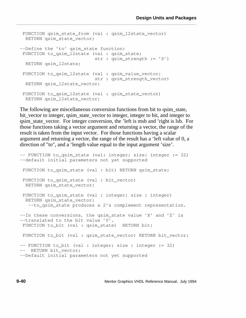
Design Units and Packages________________________________________________________________________________________________________________________
FUNCTION qsim_state_from (val : qsim_12state_vector) RETURN qsim_state_vector;
--Define the ’to’ qsim_state function: FUNCTION to_qsim_12state (val : qsim_state; str : qsim_strength := ’S’) RETURN qsim_12state;
FUNCTION to_qsim_12state (val : qsim_value_vector; str : qsim_strength_vector) RETURN qsim_12state_vector;
FUNCTION to_qsim_12state (val : qsim_state_vector) RETURN qsim_12state_vector;
The following are miscellaneous conversion functions from bit to qsim_state,bit_vector to integer, qsim_state_vector to integer, integer to bit, and integer toqsim_state_vector. For integer conversion, the ’left is msb and ’right is lsb. Forthose functions taking a vector argument and returning a vector, the range of theresult is taken from the input vector. For those functions having a scalarargument and returning a vector, the range of the result has a ‘left value of 0, adirection of "to", and a ‘length value equal to the input argument ’size’.
-- FUNCTION to_qsim_state (val: integer; size: integer := 32)--default initial parameters not yet supported
FUNCTION to_qsim_state (val : bit) RETURN qsim_state;
FUNCTION to_qsim_state (val : bit_vector) RETURN qsim_state_vector;
FUNCTION to_qsim_state (val : integer; size : integer) RETURN qsim_state_vector; --to_qsim_state produces a 2’s complement representation.
--In these conversions, the qsim_state value ’X’ and ’Z’ is --translated to the bit value ’0’. FUNCTION to_bit (val : qsim_state) RETURN bit;
FUNCTION to_bit (val : qsim_state_vector) RETURN bit_vector;
-- FUNCTION to_bit (val : integer; size : integer := 32) -- RETURN bit_vector;--Default initial parameters not yet supported
9-40 Mentor Graphics VHDL Reference Manual, July 1994

Design Units and Packages________________________________________________________________________________________________________________________
FUNCTION to_bit (val: integer; size: integer) RETURN bit_vector; --to_bit produces a 2’s complement representation.
FUNCTION to_integer (val : bit_vector) RETURN integer; -- to_integer assumes a 2’s complement representation.
--In this conversion function, the qsim_state value ’X’ and --’Z’ are translated to the integer value of the second --parameter x. By default the value is zero (0).-- FUNCTION to_integer (val: qsim_state_vector; -- x: integer := 0) --default initial parameters not yet supported.
FUNCTION to_integer (val : qsim_state_vector; x : integer) RETURN integer; --to_integer assumes a 2’s complement representation.
--Overloaded math and logic operations:
FUNCTION "AND" (l, r: qsim_state) RETURN qsim_state; -- -- AND r\l 0 1 X Z -- 0 0 0 0 0 -- 1 0 1 X X -- X 0 X X X -- Z 0 X X X
FUNCTION "OR" (l, r: qsim_state) RETURN qsim_state; -- -- OR r\l 0 1 X Z -- 0 0 1 X X -- 1 1 1 1 1 -- X X 1 X X -- Z X 1 X X
FUNCTION "NAND" (l, r: qsim_state) RETURN qsim_state; -- -- NAND r\l 0 1 X Z -- 0 1 1 1 1 -- 1 1 0 X X -- X 1 X X X -- Z 1 X X X
Mentor Graphics VHDL Reference Manual, July 1994 9-41

Design Units and Packages________________________________________________________________________________________________________________________
FUNCTION "NOR" (l, r: qsim_state) RETURN qsim_state; -- -- NOR r\l 0 1 X Z -- 0 1 0 X X -- 1 0 0 0 0 -- X X 0 X X -- Z X 0 X X
FUNCTION "XOR" (l, r: qsim_state) RETURN qsim_state; -- -- XOR r\l 0 1 X Z -- 0 0 1 X X -- 1 1 0 X X -- X X X X X -- Z X X X X
FUNCTION "NOT" (l : qsim_state) RETURN qsim_state; -- -- NOT -- 0 1 -- 1 0 -- X X -- Z X
FUNCTION "=" (l, r : qsim_state) RETURN qsim_state; -- -- "=" r\l 0 1 X Z -- 0 1 0 X X -- 1 0 1 X X -- X X X X X -- Z X X X X
FUNCTION "/=" (l, r : qsim_state) RETURN qsim_state; -- -- "/=" r\l 0 1 X Z -- 0 0 1 X X -- 1 1 0 X X -- X X X X X -- Z X X X X
FUNCTION "<" (l, r : qsim_state) RETURN qsim_state; -- -- "<" r\l 0 1 X Z -- 0 0 0 0 0 -- 1 1 0 X X -- X X 0 X X -- Z X 0 X X
9-42 Mentor Graphics VHDL Reference Manual, July 1994

Design Units and Packages________________________________________________________________________________________________________________________
FUNCTION ">" ( l, r: qsim_state) RETURN qsim_state; -- -- ">" r\l 0 1 X Z -- 0 0 1 X X -- 1 0 0 0 0 -- X 0 X X X -- Z 0 X X X
FUNCTION "<=" (l, r : qsim_state) RETURN qsim_state; -- -- "<=" r\l 0 1 X Z -- 0 1 0 X X -- 1 1 1 1 1 -- X 1 X X X -- Z 1 X X X
FUNCTION ">=" (l, r : qsim_state) RETURN qsim_state; -- -- ">=" r\l 0 1 X Z -- 0 1 1 1 1 -- 1 0 1 X X -- X X 1 X X -- Z X 1 X X
FUNCTION "+" ( l, r : qsim_state) RETURN qsim_state; -- -- "+" r\l 0 1 X Z -- 0 0 1 X X -- 1 1 0 X X -- X X X X X -- Z X X X X
FUNCTION "-" ( l, r : qsim_state) RETURN qsim_state; -- -- "-" r\l 0 1 X Z -- 0 0 1 X X -- 1 1 0 X X -- X X X X X -- Z X X X X
--The operators of &, unary +, unary -, *, /, mod, rem--**, abs are not defined for qsim_state;
The overload functions for qsim_state_vector assume the standard MentorGraphics notation of the most-significant-bit (msb) being the left- most element.All functions, unless otherwise stated, work with arrays of unequal length. The
Mentor Graphics VHDL Reference Manual, July 1994 9-43

Design Units and Packages________________________________________________________________________________________________________________________
shorter arrays will be prepended with ’0’ to make them the same length. This istrue for the relational operators to prevent expressions like("011" < "10") = TRUE .
Functions returning vector types have a result that has a length of the longestoperand, and the result has a ’left and direction equal to the ’left and direction ofthe left operand unless otherwise noted
The relational operators and logical operators work as if the qsim_state operatorwere applied individually to each operand pair. The relational operator rules forarrays apply for qsim_state_vectors. qsim_state_vectors are treated as unsignedintegers in all arithmetic operations. If either operand contains ’X’ or ’Z’, anattempt is made to compute an answer as optimistically as possible. In somecases, a partial result will be produced. Otherwise, the result will be ’X’ or anarray of ’X’s.
-- bitwise operations FUNCTION "AND" (l, r: qsim_state_vector) RETURN qsim_state_vector; FUNCTION "OR" (l, r: qsim_state_vector) RETURN qsim_state_vector; FUNCTION "NAND"(l, r: qsim_state_vector) RETURN qsim_state_vector; FUNCTION "NOR" (l, r: qsim_state_vector) RETURN qsim_state_vector; FUNCTION "XOR" (l, r: qsim_state_vector) RETURN qsim_state_vector; FUNCTION "NOT" (l : qsim_state_vector) RETURN qsim_state_vector;
For these relational operators, an algorithm is employed to provide the mostoptimistic answer possible in the case where ’X’s are present For example theresult of ("011" >= "0X1") is ’1’. In effect, a comparison is done with the ’X’replaced with a ’0’ and then repeated with the ’X’ replaced with a ’1’. If the resultsof both comparisons are the same, then that result is returned. If the results don’tmatch, an ’X’ is returned.
FUNCTION "<" (l, r: qsim_state_vector) RETURN qsim_state; FUNCTION ">" (l, r: qsim_state_vector) RETURN qsim_state; FUNCTION "=" (l, r: qsim_state_vector) RETURN qsim_state; FUNCTION "/=" (l, r: qsim_state_vector) RETURN qsim_state; FUNCTION ">=" (l, r: qsim_state_vector) RETURN qsim_state; FUNCTION "<=" (l, r: qsim_state_vector) RETURN qsim_state;
9-44 Mentor Graphics VHDL Reference Manual, July 1994

Design Units and Packages________________________________________________________________________________________________________________________
Addition and subtraction of qsim_state_vectors use the table defined forqsim_state "+" and "-" operators. The result vector is the size of the largeroperand. The range of the result array will have a ’left and direction equal to the’left and direction of the left operand. The result will be as optimistic as possiblewhen ’X’s are present. For example: -- ("01X0" + "0100") = "10X0"-- ("01X0" + "0110") = "1XX0"
FUNCTION "+" (l, r: qsim_state_vector) RETURN qsim_state_vector; FUNCTION "-" (l, r: qsim_state_vector) RETURN qsim_state_vector;
For these multiplying operators, the result is the size of the larger operand with a’left and direction of the left operand. The operators "*", "/", "mod", "rem", and"**" will do the following: convert the entry to a natural universal integer,perform the operation, and truncate the result to the size of the result array. Thesize of the result is the same as for addition and subtraction: the size of the largeroperand. The size of the result for "*" is the sum of the lengths of the twooperands. If any ’X’s or ’Z’s are present in either operand, the complete result isall ’X’s. FUNCTION "*" (l, r: qsim_state_vector) RETURN qsim_state_vector; FUNCTION "/" (l, r: qsim_state_vector) RETURN qsim_state_vector; FUNCTION "MOD"(l, r: qsim_state_vector) RETURN qsim_state_vector;
--NOTE: Since the operands are treated as unsigned integers -- REM returns the same result as MOD. FUNCTION "REM"(l, r: qsim_state_vector) RETURN qsim_state_vector; FUNCTION "**" (l, r: qsim_state_vector) RETURN qsim_state_vector;
--The operators unary "+", "-" and "abs" are not defined. --"&" has the normal meaning.
Mentor Graphics VHDL Reference Manual, July 1994 9-45

Design Units and Packages________________________________________________________________________________________________________________________
--Define logic operators on bit vectors. --These differ from the standard in that they accept vectors --of different lengths.
FUNCTION "AND" (l, r : bit_vector) RETURN bit_vector; FUNCTION "OR" (l, r : bit_vector) RETURN bit_vector; FUNCTION "NAND" (l, r : bit_vector) RETURN bit_vector; FUNCTION "NOR" (l, r : bit_vector) RETURN bit_vector; FUNCTION "XOR" (l, r : bit_vector) RETURN bit_vector;
--Define addition and subtraction for bit vectors. --’left is the most significant bit and ’right is the least --significant bit. The result is the size of the larger --operand. Bit_vectors are treated as unsigned integers.
FUNCTION "+" (l, r : bit_vector) RETURN bit_vector; FUNCTION "-" (l, r : bit_vector) RETURN bit_vector;
--"*", "/", "mod", "rem", and "**" are defined to be: -- convert the entry to a natural universal integer, -- perform the operation and truncate it to the size of the -- resultant array. FUNCTION "*" (l, r : bit_vector) RETURN bit_vector; FUNCTION "/" (l, r : bit_vector) RETURN bit_vector; FUNCTION "MOD" (l, r : bit_vector) RETURN bit_vector;
--NOTE: Since the operands are treated as unsigned integers -- REM returns the same result as MOD. FUNCTION "REM" (l, r : bit_vector) RETURN bit_vector; FUNCTION "**" (l, r : bit_vector) RETURN bit_vector;
--The operators unary +, unary - and abs are not defined.
END qsim_logic;
9-46 Mentor Graphics VHDL Reference Manual, July 1994

Design Units and Packages________________________________________________________________________________________________________________________
mgc_portable.qsim_relations
SIn this package, the "=", "<", ">", etc. operators are defined for type qsim_state todeal effectively an reasonably with unknown states (’X’).
LIBRARY mentor;USE mentor.qsim_logic.ALL;
PACKAGE qsim_relations IS FUNCTION "=" ( l, r : qsim_state) RETURN boolean; -- -- "=" r\l 0 1 X Z -- 0 T F F F -- 1 F T F F -- X F F F F -- Z F F F F FUNCTION "/=" (l, r : qsim_state) RETURN boolean; -- -- "/=" r\l 0 1 X Z -- 0 F T F F -- 1 T F F F -- X F F F F -- Z F F F F FUNCTION "<" (l, r : qsim_state) RETURN boolean; -- -- "<" r\l 0 1 X Z -- 0 F F F F -- 1 T F F F -- X F F F F -- Z F F F F FUNCTION ">" (l, r: qsim_state) RETURN boolean; -- -- ">" r\l 0 1 X Z -- 0 F T F F -- 1 F F F F -- X F F F F -- Z F F F F
Mentor Graphics VHDL Reference Manual, July 1994 9-47

Design Units and Packages________________________________________________________________________________________________________________________
FUNCTION "<=" (l, r : qsim_state) RETURN boolean; -- -- "<=" r\l 0 1 X Z -- 0 T F F F -- 1 T T T T -- X T F F F -- Z T F F F FUNCTION ">=" (l, r : qsim_state) RETURN boolean; -- -- ">=" r\l 0 1 X Z -- 0 T T T T -- 1 F T F F -- X F T F F -- Z F T F F
FUNCTION same( l, r : qsim_state ) RETURN boolean; -- True equivalence FUNCTION "<" (l, r : qsim_state_vector) RETURN boolean; FUNCTION ">" (l, r : qsim_state_vector) RETURN boolean; FUNCTION "=" (l, r : qsim_state_vector) RETURN boolean; FUNCTION "/=" (l, r : qsim_state_vector) RETURN boolean; FUNCTION ">=" (l, r : qsim_state_vector) RETURN boolean; FUNCTION "<=" (l, r : qsim_state_vector) RETURN boolean;
--Only the relational operators for qsim_strength are defined.--All other operations on qsim_strength are undefined.
FUNCTION "=" (l, r : qsim_strength) RETURN boolean; -- -- "=" r\l Z R S I -- Z T F F F -- R F T F F -- S F F T F -- I F F F F FUNCTION "/="( l, r : qsim_strength) RETURN boolean; -- -- "/=" r\l Z R S I -- Z F T T F -- R T F T F -- S T T F F -- I F F F F
9-48 Mentor Graphics VHDL Reference Manual, July 1994
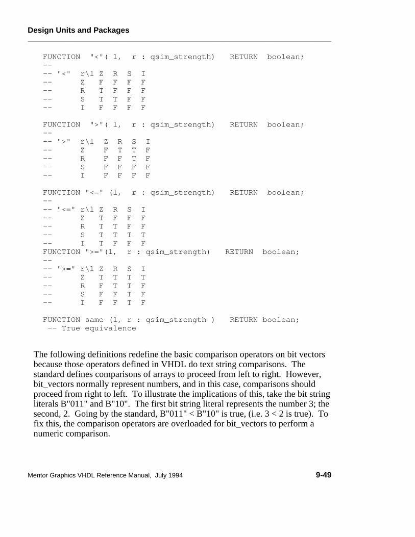
Design Units and Packages________________________________________________________________________________________________________________________
FUNCTION "<"( l, r : qsim_strength) RETURN boolean; -- -- "<" r\l Z R S I -- Z F F F F -- R T F F F -- S T T F F -- I F F F F FUNCTION ">"( l, r : qsim_strength) RETURN boolean; -- -- ">" r\l Z R S I -- Z F T T F -- R F F T F -- S F F F F -- I F F F F FUNCTION "<=" (l, r : qsim_strength) RETURN boolean; -- -- "<=" r\l Z R S I -- Z T F F F -- R T T F F -- S T T T T -- I T F F F FUNCTION ">="(l, r : qsim_strength) RETURN boolean; -- -- ">=" r\l Z R S I -- Z T T T T -- R F T T F -- S F F T F -- I F F T F FUNCTION same (l, r : qsim_strength ) RETURN boolean; -- True equivalence
The following definitions redefine the basic comparison operators on bit vectorsbecause those operators defined in VHDL do text string comparisons. Thestandard defines comparisons of arrays to proceed from left to right. However,bit_vectors normally represent numbers, and in this case, comparisons shouldproceed from right to left. To illustrate the implications of this, take the bit stringliterals B"011" and B"10". The first bit string literal represents the number 3; thesecond, 2. Going by the standard, B"011" < B"10" is true, (i.e. 3 < 2 is true). Tofix this, the comparison operators are overloaded for bit_vectors to perform anumeric comparison.
Mentor Graphics VHDL Reference Manual, July 1994 9-49

Design Units and Packages________________________________________________________________________________________________________________________
FUNCTION "<" (l, r : bit_vector) RETURN bit; FUNCTION ">" (l, r : bit_vector) RETURN bit; FUNCTION "=" (l, r : bit_vector) RETURN bit; FUNCTION "/=" (l, r : bit_vector) RETURN bit; FUNCTION ">=" (l, r : bit_vector) RETURN bit; FUNCTION "<=" (l, r : bit_vector) RETURN bit;
FUNCTION "<" (l, r : bit_vector) RETURN boolean; FUNCTION ">" (l, r : bit_vector) RETURN boolean; FUNCTION "=" (l, r : bit_vector) RETURN boolean; FUNCTION "/=" (l, r : bit_vector) RETURN boolean; FUNCTION ">=" (l, r : bit_vector) RETURN boolean; FUNCTION "<=" (l, r : bit_vector) RETURN boolean;
END qsim_relations;
9-50 Mentor Graphics VHDL Reference Manual, July 1994

Attributes________________________________________________________________________________________________________________________
Section 10Attributes
This section includes information on attributes, both user-defined and predefined.Attributes allow you to associate information with an item. The followingordered list shows the constructs and topics this section discusses:
Attribute Overview 10-1attribute_name 10-3
Predefined Attributes 10-5Detailed Predefined Attribute Description 10-7Array Object Attributes 10-8Block Attributes 10-24Signal Attributes 10-28Type Attributes 10-40
User-Defined Attributes 10-53attribute_declaration 10-54attribute_specification 10-55
Attribute OverviewAn attribute is a named characteristic that is associated with one or more items ina VHDL description. There are two varieties of attributes:
● Predefined attributes are part of the predefined language environment.Predefined attributes are useful for examining the characteristics of arrays,types, and blocks or for querying and manipulating the values of signals.
● User-defined attributes allows you to add additional information that cannotbe described using other VHDL constructs. For example, you might want toback-annotate physical characteristics such as output and input capacitances toa design.
Mentor Graphics VHDL Reference Manual, July 1994 10-1

Attributes________________________________________________________________________________________________________________________
���������������������������������������������������������������������������������������������������������������������������������������������������������������������������������������������������������������������������������������������������������������������������������������������������������������������������������������������������������������������������������������������������������������������������������������������������������������������������������������������������������������������������������������������������������������������������������������������������������������������������������������������������������������������������������������������������������������������������������������������������������������������������������������������������������������������������������������������������������������������������������������������������������������������������������������������������������������������������������������������������������������������������������������������������������������������������������������������
Attributes
User-Defined Attributes
SignalsTypes
Configurations
Design Entities
ComponentsAttributes
Packages
Naming, Scope, and Visibility
Lexical Elements
Expressions
Design Units
Subprograms
Declarations
Statements
Predefined Attributes
Array Object
Block
Signal
Type
Figure 10-1. Attributes
10-2 Mentor Graphics VHDL Reference Manual, July 1994

Attributes________________________________________________________________________________________________________________________
attribute_nameAn attribute name denotes a particular characteristic associated with a type,subprogram, object, design unit, component, or label.
Construct Placementname
Syntax
attribute_name ::= prefix ’ attribute_designator [ ( expression ) ]
attribute_designator ::= attribute_simple_name
Definitions
■ attribute_designatorThe attribute designator names the attribute that you wish to use.
DescriptionWhen referenced by its name, an attribute returns certain information about theitem named in the prefix, such as length of an array or whether a signal is active.
The apostrophe character (’) designates that the identifier immediately followingit is an attribute. (The apostrophe character is also used to designate qualifiedexpressions and to enclose character literals.) The following code exampleshows the use of a predefined attribute:
clock’delayed(50 ns) -- -- "clock" is the prefix (signal name) -- "’delayed" is the attribute designator (simple name) -- (50 ns) is the optional static_expression -- This attribute creates and accesses a signal that has -- the same value as "clock," except it is delayed 50 ns.
The prefix indicates the object that the attribute relates to. The prefix for apredefined attribute denotes a particular array, block, signal, or type. On theother hand, the prefix for a user-defined attribute may denote an entitydeclaration, an architecture body, a configuration, a procedure, a function, apackage, a type, a subtype, a constant, a signal, a variable, a component, or a
Mentor Graphics VHDL Reference Manual, July 1994 10-3

Attributes________________________________________________________________________________________________________________________
label. In the preceding example, the prefix clock is of type signal; therefore, theattribute relates to the signal called clock.
The attribute designator is the name of the attribute that you wish to use. In thepreceding example, delayed is the attribute designator.
The optional expression is an expression that designates a specific parameter forthe attribute. In the preceding example, the expression is "50 ns". Not all thepredefined attributes allow parameters. The expression in the attribute name maybe required or may be optional, depending on the particular attribute definition.
The following examples show the declaration of two types and the use ofattribute names to determine information about those types. These codefragments have been taken out of context from a description.
Type declarations:TYPE color IS(red, white, blue, orange, purple);TYPE vector IS ARRAY (1 TO 10, 1 TO 15) OF integer;
color’val(2) --Returns the value of element in position 2 --of the type "color" which is blue (positions --start at zero)
vector’right(1) --returns right bound of the specified --index"1" in the array "vector" --which is 10
10-4 Mentor Graphics VHDL Reference Manual, July 1994

Attributes________________________________________________________________________________________________________________________
Predefined AttributesPredefined attributes are a means of determining types, ranges, and values thatrelate to design items. For example, you can examine array bounds or determinewhether a certain condition is true or false. You can use some attributes assubprogram parameters. For information on this topic, refer to page 7-8.
Each predefined attribute relates to only one valid object kind. This object kindcorresponds to the prefix you use before the attribute designator. Eachpredefined attribute falls into one of the four object kind categories: arrayobjects, blocks, signals (scalar or composite), and types (scalar, composite orfile). For example, if you want information about a signal, you use a signalattribute or if you want information about an array, you use an array objectattribute. It would not be logical, for instance, to determine if an integer (scalartype) was stable at a certain time, because only signals can be stable.
Table 10-1 lists each predefined attribute name and the related object kind.
The object kind should not be confused with the attribute kind. The attributekind tells you what the attribute actually is and the rules for using the attributevalue. The attribute kinds are as follows:
● Function ● Range ● Signal ● Type ● Value
For example, the attribute ’low of the array object kind is an attribute of thefunction kind. This means that when you use the attribute, it actually calls afunction that returns a value. Also, all the rules for functions apply to theattribute.
Another example is the attribute ’quiet that has an object kind of signal and is anattribute of signal kind. Therefore, if you state test’delayed (10 ns), there actuallyexists a signal called "test’delayed", which is "test" delayed by 10 ns, with all therules that apply to signals. You can use this signal just as you would the signal"test".
Mentor Graphics VHDL Reference Manual, July 1994 10-5
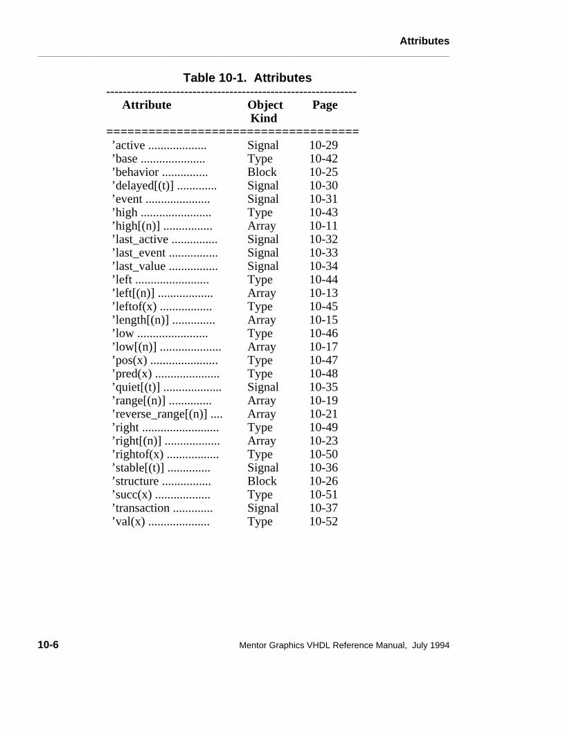
Attributes________________________________________________________________________________________________________________________
Table 10-1. Attributes-------------------------------------------------------------
Attribute Object Kind
Page
====================================’active ...................’base .....................’behavior ...............’delayed[(t)] .............’event .....................’high .......................’high[(n)] ................’last_active ............... ’last_event ................’last_value ................’left ........................’left[(n)] ..................’leftof(x) .................’length[(n)] ..............’low .......................’low[(n)] ....................’pos(x) ......................’pred(x) .....................’quiet[(t)] ...................’range[(n)] ..............’reverse_range[(n)] ....’right .........................’right[(n)] ..................’rightof(x) .................’stable[(t)] ..............’structure ................’succ(x) ..................’transaction .............’val(x) ....................
SignalType Block SignalSignalTypeArraySignalSignalSignalTypeArrayTypeArrayTypeArrayTypeTypeSignalArrayArrayType ArrayTypeSignalBlockTypeSignalType
10-2910-4210-2510-3010-3110-4310-1110-3210-3310-3410-4410-1310-4510-1510-4610-1710-4710-4810-3510-1910-2110-4910-2310-5010-3610-2610-5110-3710-52
10-6 Mentor Graphics VHDL Reference Manual, July 1994

Attributes________________________________________________________________________________________________________________________
Detailed Predefined Attribute Description
The predefined attributes are divided into four categories according to theirobject kind. If you are not sure which object kind the attribute relates to, refer toTable 10-1 on page 10-6. A discussion on each object kind precedes a detaileddescription of each predefined attribute for that object kind.
The descriptions for the attributes appear in the following format:
KindThis subsection designates which kind the attribute is (attribute kind). Anattribute can be a function, range, signal, type, or value. The attribute kind is notthe object kind. Table 10-1 on page 10-6 lists the object kind for each attribute.
PrefixThis subsection defines the valid prefix for the attribute. The prefix is the objectname or function call of the item to which to apply the attribute.
ParameterThis subsection defines the parameter (if applicable) for the attribute. Youprovide the parameter, which is a value that specifies an exact location or time.
In the descriptions, the parameter is indicated by a letter set off in parentheses(which are required) and, in some cases, brackets (which are not used in thecode). If you do not provide a value for a parameter, it assumes a default value.
Result TypeThis subsection discusses the resulting type after evaluating the attribute.
Evaluation Result This subsection discusses the results of the attribute evaluation.
ExampleThis subsection contains an example for using the attribute and the results afterevaluation.
RestrictionsThis subsection discusses any restrictions that apply to the attribute.
Mentor Graphics VHDL Reference Manual, July 1994 10-7

Attributes________________________________________________________________________________________________________________________
Array Object Attributes
You use array object attributes for passing array parameter information to otherarrays (such as unconstrained arrays). Aan important concept to keep in mindwhen using array object attributes, is that the evaluation results are the bounds ofthe array, not the contents of the array. For more information on array types,refer to page 5-22.
For this subsection, one array is used for the examples. This array is calledmatrix as the following code shows:
TYPE arr_1 IS ARRAY (integer RANGE <>) OF integer; VARIABLE matrix: arr_1(1 TO 3, 9 DOWNTO 6);--array var. decl.
The preceding line of code creates a 3 by 4, two-dimensional array. Thefollowing is a representation of this array:
INDEX
1
2
3
*
*
*
*
*
*
*
*
*
*
*
*
9 8 7 6
In the previous array, the star "*" represents the array contents. Since thepredefined attributes for array objects relate to the array bounds, the examples donot require actual array element values. When specifying a parameter [(n)], youare either referencing an index row from above the dashed line, or an indexcolumn to the left of the solid line. For example: matrix’high(1) -- parameter n = 1
The parameter (1) is referencing the boxed column shown in the followingdiagram:
10-8 Mentor Graphics VHDL Reference Manual, July 1994

Attributes________________________________________________________________________________________________________________________
INDEX
1
2
3
*
*
*
*
*
*
*
*
*
*
*
*
N = 1
9 8 7 6
If you specify a parameter of (2) as follows: matrix’high(2) -- parameter N = 2
the parameter (2) is referencing the boxed row shown in the following matrix:
INDEX
1
2
3
*
*
*
*
*
*
*
*
*
*
*
*
N = 2
9 8 7 6
You cannot use parameter values that exceed the dimension of the array. Forexample, if you specify "n = 3" using the example array, an error occurs becausethe example array is two-dimensional, not three-dimensional.
When you are examining arrays, the ascending and descending range refers to thedirection of the index. The boxed regions of Figure 10-2 illustrate this concept.
Mentor Graphics VHDL Reference Manual, July 1994 10-9

Attributes________________________________________________________________________________________________________________________
INDEX
1
2
3
*
*
*
*
*
*
*
*
*
*
*
*
Ascending
left = low
right = high
left = high right = low
Descending
9 8 7 6
Figure 10-2. Array Direction
In the preceding array, the vertical index is ascending (1 TO 3). Therefore,"left" or "low" corresponds to vertical index "1", and "right" or "high"corresponds to vertical index "3".
The horizontal index is descending (9 DOWNTO 6). Therefore, "left" or "high"corresponds to horizontal index "9", and "right" or "low" corresponds tohorizontal index "6". The direction relationships between the range indices aredetermined by using this table:
RangeConstraintBound
Ascending Range DescendingRange
Left-most = Lowest value Highest valueRight-most = Highest value Lowest valueLowest = Left-most value Right-most valueHighest = Right-most value Left-most value
The following subsections describe each predefined array object attribute indetail.
10-10 Mentor Graphics VHDL Reference Manual, July 1994

Attributes________________________________________________________________________________________________________________________
’high[(n)]
KindFunction
PrefixAny valid array object prefix or a prefix that designates a constrained arraysubtype.
ParameterAn expression of type universal_integer, that can be evaluated during the currentdesign unit analysis (locally static expression). The value of this expressioncannot be larger than the array object dimension. If you do not include thisexpression, the default value is one (1).
Result TypeThe result type corresponds to the type indicated by the specified parameter [(n)].
Evaluation Result The result returns the upper bound of the index range specified by the parameter[(n)]. The index range is all the possible index values in a specified range.
Mentor Graphics VHDL Reference Manual, July 1994 10-11

Attributes________________________________________________________________________________________________________________________
ExampleThe following example shows an attribute portion of a code description:
TYPE arr_1 IS ARRAY (integer RANGE <>) OF integer; VARIABLE matrix: arr_1(1 TO 3, 9 DOWNTO 6);--array var. decl.matrix’high(1) --parameter n is 1 - Returned value is 3matrix’high(2) --parameter n is 2 - Returned value is 9
When the parameter [(n)] is 1, the boxed column is examined:
INDEX
1
2
3
*
*
*
*
*
*
*
*
*
*
*
*
9 8 7 6
The value that returns is "3", which is the value of the upper bound of the arrayindex that the parameter (1) specifies.
When the parameter [(n)] is 2, the horizontal row is examined. In this example, a"9" is returned.
10-12 Mentor Graphics VHDL Reference Manual, July 1994

Attributes________________________________________________________________________________________________________________________
’left[(n)]
KindFunction
PrefixAny valid array object prefix or a prefix that designates a constrained arraysubtype.
ParameterAn expression of type universal_integer, which can be evaluated during thecurrent design unit analysis (locally static expression). The value of thisexpression cannot be larger than the array object dimension. If you do notinclude this expression, the default value is one (1).
Result TypeThe result type corresponds to the left bound type indicated by the specifiedparameter [(n)].
Evaluation Result The result returns the left bound of the index range specified by the parameter[(n)]. The index range is all the possible index values in a specified range.
Mentor Graphics VHDL Reference Manual, July 1994 10-13

Attributes________________________________________________________________________________________________________________________
ExampleThe following example shows an attribute portion of a code description:
TYPE arr_1 IS ARRAY (integer RANGE <>) OF integer; VARIABLE matrix: arr_1(1 TO 3, 9 DOWNTO 6);--array var. decl.matrix’left(2) --parameter N is 2 - Returned value is 9matrix’left(1) --parameter N is 1 - Returned value is 1
When the parameter [(n)] is "2", the boxed column is examined:
INDEX
1
2
3
*
*
*
*
*
*
*
*
*
*
*
*
9 8 7 6
The value that returns is "9", which is the value of the left bound that theparameter (2) specifies.
When the parameter [(n)] is "1", the vertical column is examined. In thisexample, a "1’ is returned.
10-14 Mentor Graphics VHDL Reference Manual, July 1994

Attributes________________________________________________________________________________________________________________________
’length[(n)]
KindValue
PrefixAny valid array object prefix or a prefix that designates a constrained arraysubtype.
ParameterAn expression of type universal_integer, which can be evaluated during thecurrent design unit analysis (locally static expression). The value of thisexpression cannot be larger than the array object dimension. If you do notinclude this expression, the default value is one (1).
Result Typeuniversal_integer
Evaluation Result The result is the number of values within the index range specified by theparameter. The following is the algebraic expression for ’length[(n)]:
’length(n) = ’high(n) - ’low(n) + 1
If you specify a prefix that designates a null array, the evaluation result is zero.
Mentor Graphics VHDL Reference Manual, July 1994 10-15

Attributes________________________________________________________________________________________________________________________
ExampleThe following example shows an attribute portion of a code description:
TYPE arr_1 IS ARRAY (integer RANGE <>) OF integer; VARIABLE matrix: arr_1(1 TO 3, 9 DOWNTO 6);--array var. decl.matrix’length(1) --parameter n is 1 - Returned value is 3
Since the parameter [(n)] is "1", the boxed column is examined:
INDEX
1
2
3
*
*
*
*
*
*
*
*
*
*
*
*
-
+ 1 9 8 7 6
The value that returns is "3", which is the number of values within the specifiedparameter (1). The return value is determined by substituting values in thealgebraic expression, as the following example shows:
’length(1) = ’high(1) - ’low(1) + 1’length(1) = 3 - 1 + 1’length(1) = 3
10-16 Mentor Graphics VHDL Reference Manual, July 1994
Attributes________________________________________________________________________________________________________________________
’low[(n)]
KindFunction
PrefixAny valid array object prefix or a prefix that designates a constrained arraysubtype.
ParameterAn expression of type universal_integer, which can be evaluated during thecurrent design unit analysis (locally static expression). The value of thisexpression cannot be larger than the array object dimension. If you do notinclude this expression, the default value is one (1).
Result TypeThe result type corresponds to the type indicated by the specified parameter [(n)].
Evaluation Result The result returns the lower bound of the index range that the parameter [(n)]specifies. The index range is all the possible index values in a specified range.
Mentor Graphics VHDL Reference Manual, July 1994 10-17

Attributes________________________________________________________________________________________________________________________
Example The following example shows an attribute portion of a code description:
TYPE arr_1 IS ARRAY (integer RANGE <>) OF integer; VARIABLE matrix: arr_1(1 TO 3, 9 DOWNTO 6);--array var. decl.matrix’low(2) --parameter n is 2 - Returned value is 6matrix’low(1) --parameter n is 1 - Returned value is 1
When the parameter [(n)] is "2", the boxed column is examined:
INDEX
1
2
3
*
*
*
*
*
*
*
*
*
*
*
*
9 8 7 6
The value returned is "6", which is the value of the right bound that the parameter(2) specifies.
When the parameter [(n)] is "1", the vertical column is examined. In thisexample, the returned value is "1"
10-18 Mentor Graphics VHDL Reference Manual, July 1994

Attributes________________________________________________________________________________________________________________________
’range[(n)]
KindRange
PrefixAny valid array object prefix or a prefix that designates a constrained arraysubtype.
ParameterAn expression of type universal_integer, which can be evaluated during thecurrent design unit analysis (locally static expression). The value of thisexpression cannot be larger than the array object dimension. If you do notinclude this expression, the default value is one (1).
Result TypeThe result type corresponds to the type indicated by the specified parameter [(n)].
Evaluation Result The result is the range of the array you specify in the prefix, using the reservedword to if ascending, and downto if descending. The result is not a visible stringbut a value you can use as a range constraint or in a for statement.
Mentor Graphics VHDL Reference Manual, July 1994 10-19

Attributes________________________________________________________________________________________________________________________
ExampleThe following example shows an attribute portion of a code description: matrix’range(1)
Since the parameter [(n)] is "1", the boxed column is examined:
INDEX 9 8 7 6
1
2
3
*
*
*
*
*
*
*
*
*
*
*
*
TO
The value of the attribute is "1 to 3", which is the value of the ascending range ofthe specified parameter (1). This returned value can be used only whenspecifying a range.
● The following example shows the specification of a range of another array byusing the preceding example: x: ARRAY (1 TO 4, matrix’range(1));
This is equivalent to the following:x: ARRAY (1 TO 4, 1 TO 3); -- 4 by 3, two-dimen. array
● An example using ’range in a loop statement follows:FOR test IN matrix’range(1) LOOP . . .
This is equivalent to the following:FOR test IN 1 TO 3 LOOP . . .
10-20 Mentor Graphics VHDL Reference Manual, July 1994

Attributes________________________________________________________________________________________________________________________
’reverse_range[(n)]
KindRange
PrefixAny valid array object prefix or a prefix that designates a constrained arraysubtype.
ParameterAn expression of type universal_integer, which can be evaluated during thecurrent design unit analysis (locally static expression). The value of thisexpression cannot be larger than the array object dimension. If you do notinclude this expression, the default value is one (1).
Result TypeThe result type corresponds to the type indicated by the specified parameter [(n)].
Evaluation Result The result is the conversion of ascending range to a descending range, or theconversion of a descending to an ascending range, using the specified parameter.
Mentor Graphics VHDL Reference Manual, July 1994 10-21

Attributes________________________________________________________________________________________________________________________
Example The following example shows an attribute portion of a code description: matrix’reverse_range(1)
Since the parameter [(n)] is "1", the boxed column is examined:
INDEX
1
2
3
*
*
*
*
*
*
*
*
*
*
*
*
DOWNTO
9 8 7 6
The value of the attribute is "3 downto 1", which is the value of the descendingrange (converted from ascending range) of the specified parameter (1). Thisreturned value can be used only when specifying a range.
● The following example shows the specification of a range of another array byusing the preceding example: x: ARRAY (1 TO 4, matrix’reverse_range(1));
This is equivalent to the following:x: ARRAY (1 TO 4, 3 DOWNTO 1); -- 4 by 3, two-dimen. array
● An example using ’range in a loop statement follows:FOR test IN matrix’reverse_range(1) LOOP . . .
This is equivalent to the following:FOR test IN 3 DOWNTO 1 LOOP . . .
10-22 Mentor Graphics VHDL Reference Manual, July 1994

Attributes________________________________________________________________________________________________________________________
’right[(n)]
KindFunction
PrefixAny valid array object prefix or a prefix that designates a constrained arraysubtype.
ParameterAn expression of type universal_integer, which can be evaluated during thecurrent design unit analysis (locally static expression). The value of thisexpression cannot be larger than the array object dimension. If you do notinclude this expression, the default value is one (1).
Result TypeThe result type corresponds to the type indicated by the specified parameter [(n)].
Evaluation Result The result returns the right bound of the index range that the parameter [(n)]specifies. The index range is all the possible index values in a specified range.
Mentor Graphics VHDL Reference Manual, July 1994 10-23

Attributes________________________________________________________________________________________________________________________
ExampleThe following example shows an attribute portion of a code description:
TYPE arr_1 IS ARRAY (integer RANGE <>) OF integer; VARIABLE matrix: arr_1(1 TO 3, 9 DOWNTO 6);--array var. decl. matrix’right(2) --parameter n is 2 - Returns value of 6 matrix’right(1) --parameter n is 1 - Returns value of 3
When the parameter [(n)] is "2", the boxed column is examined:
INDEX
1
2
3
*
*
*
*
*
*
*
*
*
*
*
*
9 8 7 6
The value that returns is "6", which is the value of the right bound that theparameter (2) specifies.
When the parameter [(n)] is "1", the vertical column is examined. In thisexample, the returned value is "3".
Block Attributes
Block attributes provide you with a means for checking whether certainconditions exist within a block or for returning certain information about theblock.
10-24 Mentor Graphics VHDL Reference Manual, July 1994

Attributes________________________________________________________________________________________________________________________
’behavior
KindValue
PrefixAny block (designated by the corresponding block label) or design entity(designated by the corresponding architecture name).
Result TypeBoolean
Evaluation Result The result of evaluating the attribute is TRUE if the specified block (specified bythe block statement or design entity) does not contain a component instantiationstatement. If a component instantiation statement is present, the attribute value isFALSE.
If the result is TRUE, the code contains a behavioral description.
ExampleThe following example shows a block within an architecture:
ARCHITECTURE sig_test OF test ISSIGNAL tester : wired_or bit_vector BUS; -- signal decl.SIGNAL a, b, c : bit;
BEGINsig_assign: -- block labelBLOCK (tester = ’1’) -- guard expression SIGNAL z : bit_vector; -- block_declarative_item DISCONNECT tester : bit_vector AFTER 10 ns;BEGIN z <= GUARDED a; -- "z" gets "a" if "test" = ’1’END BLOCK sig_assign;
END sig_test;
The following example shows the use of the predefined attribute ’behavior inrelation to the preceding example:
sig_assign’behavior
The value that returns from the preceding code is TRUE because the blocksig_assign does not contain a component instantiation statement.
Mentor Graphics VHDL Reference Manual, July 1994 10-25

Attributes________________________________________________________________________________________________________________________
’structure
KindValue
PrefixAny block (designated by the corresponding block label) or design entity(designated by the corresponding architecture name).
Result TypeBoolean
Evaluation Result The result of evaluating the attribute is TRUE if the specified block (specified bythe block statement or design entity) does not contain a signal assignmentstatement or concurrent statement that contains a signal assignment statement.The value is FALSE for any other case.
If the result is TRUE, it informs you that the code contains a structureddescription.
10-26 Mentor Graphics VHDL Reference Manual, July 1994
Attributes________________________________________________________________________________________________________________________
ExampleThe following example shows a block within an architecture:
ARCHITECTURE sig_test OF test ISSIGNAL tester : wired_or bit_vector BUS; -- signal decl.SIGNAL a, b, c : bit;
BEGINsig_assign: --block label BLOCK (tester = ’1’) -- guard expression SIGNAL z : bit_vector; -- block_declarative_item DISCONNECT tester : bit_vector AFTER 10 ns;BEGIN z <= GUARDED a; --z gets a if "test" = ’1’--sig. assign.END BLOCK sig_assign;
END sig_test;
The following example shows the use of the predefined attribute ’structure inrelation to the preceding example:
sig_assign’structure
The value that returns from the preceding code is FALSE because the blocksig_assign contains a signal assignment statement.
Mentor Graphics VHDL Reference Manual, July 1994 10-27

Attributes________________________________________________________________________________________________________________________
Signal Attributes
You use signal attributes to determine if certain signal conditions are true, toreturn information about signals, or to add delay time to signals. An importantconcept to keep in mind is that the ’delayed signal attribute is actually a signal ofthe same base type as the prefix. Figure 10-3 shows an example of this concept.
time (ns)
preset
preset’delayed
ASSERT NOT(preset’delayed(5 ns) = ’1’ AND preset = ’0’) REPORT "Check Failed" SEVERITY warning;
25
Code Portion Signal Waveforms
2015 30 35
(bit)
(bit)
Figure 10-3. Signal Attribute Concept
The previous example shows the signal attribute ’delayed combined with thesignal preset (the prefix) to create another signal preset’delayed. This signalis preset delayed by 5 ns. You can use the signal attribute signal in severalways, as the following list shows:
● Sensitivity lists of process and wait statements
● Guard expressions
● Read the signal
You cannot make assignments to the attribute signal. The remaining signalattributes are functions that return values about a signal. For more informationon signals, refer to Section 11.
The following subsections discuss each predefined signal attribute in detail.Examples of the signal attributes are more informative if they are shown together.Therefore, there is one example on page 10-38 that shows the use and effects ofall the signal attributes.
10-28 Mentor Graphics VHDL Reference Manual, July 1994

Attributes________________________________________________________________________________________________________________________
’active
KindFunction
PrefixAny signal designated by the signal name. All the expressions in the signal namecan only depend on constants or generics.
Result TypeBoolean
Evaluation Result If the signal that the prefix specifies is active while in the current simulationcycle, the return result for a scalar signal is a value of TRUE .
If any scalar subelement specified by the prefix is active, the return result for acomposite signal is a value of TRUE .
If the preceding conditions are not met, the return value is FALSE.
ExampleFor an example of this attribute in contrast to all the other signal attributes, referto page 10-38.
Mentor Graphics VHDL Reference Manual, July 1994 10-29

Attributes________________________________________________________________________________________________________________________
’delayed[(t)]
KindSignal
PrefixAny signal designated by the signal name. All the expressions in the signal namecan depend only on constants or generics.
ParameterA static expression of type time. Type time is a predefined physical type (refer toSection 5) from package "standard" (refer to page 9-18). The static expressioncannot be negative. If you do not specify the parameter (t), it defaults to 0 ns.
Result TypeThe result type corresponds to the base type of the specified prefix.
Evaluation Result The result is a new signal that is the prefix signal delayed by the period of timespecified by the parameter (t).
If the default value of 0 ns is specified as the parameter, the following expressionis not the same (for one simulation cycle) only if the signal has just changed. Ifthe signal has not just changed, then: signal_name’delayed(0 ns) = signal_name where "signal_name" is the prefix.
ExampleFor an example of this attribute in contrast to all the other signal attributes, referto page 10-38.
10-30 Mentor Graphics VHDL Reference Manual, July 1994

Attributes________________________________________________________________________________________________________________________
’event
KindFunction
PrefixAny signal designated by the signal name. All the expressions in the signal namecan depend only on constants or generics.
Result TypeBoolean
Evaluation Result If an event on the signal specified by the prefix has just occurred while in thecurrent simulation cycle, the return result for a scalar signal is a value of TRUE.
If an event on any scalar subelement, that the prefix specifies, has just occurredwhile in the current simulation cycle, the return result for a composite signal is avalue of TRUE .
If the preceding conditions are not met, the return value is FALSE.
ExampleFor an example of this attribute in contrast to all the other signal attributes, referto page 10-38.
Mentor Graphics VHDL Reference Manual, July 1994 10-31

Attributes________________________________________________________________________________________________________________________
’last_active
KindFunction
PrefixAny signal designated by the signal name. All the expressions in the signal namecan depend only on constants or generics.
Result TypeThe result type is type time, which is a predefined physical type (refer to Section5) from package "standard" (refer to page 9-18).
Evaluation Result The result is the elapsed time value since the signal specified by the prefix wasactive.
For composite signals, the value that returns is the last time any element in thecomposite was active.
ExampleFor an example of this attribute in contrast to all the other signal attributes, referto page 10-38.
10-32 Mentor Graphics VHDL Reference Manual, July 1994

Attributes________________________________________________________________________________________________________________________
’last_event
KindFunction
PrefixAny signal designated by the signal name. All the expressions in the signal namecan depend only on constants or generics.
Result TypeThe result type is type time, which is a predefined physical type (refer to Section5) from package "standard" (refer to page 9-18).
Evaluation Result Because an event occurred on the signal specified by the prefix, the result is theelapsed time value.
For composite signals, the value that returns is the last time any element in thecomposite had an event.
ExampleFor an example of this attribute in contrast to all the other signal attributes, referto page 10-38.
Mentor Graphics VHDL Reference Manual, July 1994 10-33

Attributes________________________________________________________________________________________________________________________
’last_value
KindFunction
PrefixAny signal designated by the signal name. All the expressions in the signal namecan depend only on constants or generics.
Result TypeThe result type corresponds to the base type of the specified prefix.
Evaluation Result The result is the value of the signal specified by the prefix immediately before thesignal changed value.
For composite signals, the value that returns is the last time any element in thecomposite changed value.
ExampleFor an example of this attribute in contrast to all the other signal attributes, referto page 10-38.
10-34 Mentor Graphics VHDL Reference Manual, July 1994

Attributes________________________________________________________________________________________________________________________
’quiet[(t)]
KindSignal
PrefixAny signal designated by the signal name. All the expressions in the signal namecan depend only on constants or generics.
ParameterA static expression of type time, which must not be negative. Type time is apredefined physical type (refer to Section 5) from package "standard" (refer topage 9-18). If you do not specify the parameter (t), it defaults to 0 ns.
Result TypeBoolean
Evaluation Result If the signal has not been active (quiet) for the period of time specified by theparameter (t), the result is a signal with a value of TRUE .
If the default value of 0 ns is specified as the parameter, the result is TRUE onlyif the signal is quiet for the current simulation cycle.
If the preceding conditions are not met, the value of the signal is FALSE.
ExampleFor an example of this attribute in contrast to all the other signal attributes, referto page 10-38.
Mentor Graphics VHDL Reference Manual, July 1994 10-35

Attributes________________________________________________________________________________________________________________________
’stable[(t)]
KindSignal
PrefixAny signal designated by the signal name. All the expressions in the signal namecan depend only on constants or generics.
ParameterA static expression of type time, which must not be negative. Type time is apredefined physical type (refer to Section 5) from package "standard" (refer topage 9-18). If you do not specify the parameter (t), it defaults to 0 ns.
Result TypeBoolean
Evaluation Result If an event has not occurred on the signal for the period of time specified by theparameter (t), the result is a signal with a value of TRUE . If the precedingcondition is not met, the value of the signal is FALSE.
If the parameter is omitted, it defaults to 0 ns. In this case, the value of the signalis FALSE (for one simulation cycle) only if the signal has just changed. (In otherwords, signal’stable(0) = (signal’delayed(0) = signal), where signal is the name ofthe signal.)
ExampleFor a comparison of this attribute with other signal attributes, refer to page 10-38.
10-36 Mentor Graphics VHDL Reference Manual, July 1994

Attributes________________________________________________________________________________________________________________________
’transaction
KindSignal
PrefixAny signal designated by the signal name. All the expressions in the signal namecan depend only on constants or generics.
Result TypeThe result type is type bit, which is a predefined enumeration type (refer toSection 5) defined in package "standard" (refer to page 9-18).
Evaluation Result If, while in a simulation cycle, the signal becomes active, the result of thisattribute is a signal that is the inverse of its previous value.
ExampleFor an example of this attribute in contrast to all the other signal attributes, referto page 10-38.
Mentor Graphics VHDL Reference Manual, July 1994 10-37
Attributes________________________________________________________________________________________________________________________
Signal Attribute Example
The following code shows a simple process that is sensitive on the signal clk andmakes assignments to the signal sig (these signals are of type Boolean and aredeclared elsewhere):
signal_att_example:PROCESS (clk) --process is sensitive to the signal "clk"
VARIABLE x : bit := ’0’;BEGIN
IF clk = ’1’ THEN x := NOT x; END IF;sig <= x AFTER 0 ns; -- signal assignment
END PROCESS signal_att_example;
The previous example shows that sig gets the value of x at every edge of thesignal clk. This means that sig is active at every edge of clk even if the valueof sig does not change.
Figure 10-4 shows the attribute signals in relation to the preceding example. Thesignal attributes that have the option to specify a time parameter are denoted witha value of "t". The "*" indicates an attribute value of TRUE.
The following relationships between the signal attributes exist:
● The attribute ’stable tracks the attribute ’event.
● The attribute ’transaction tracks the attribute ’active.
● The attribute ’quiet tracks the attribute ’active.
● The attribute ’last_event tracks the attribute ’event.
● The attribute ’last_active tracks the attribute ’active.
10-38 Mentor Graphics VHDL Reference Manual, July 1994

Attributes________________________________________________________________________________________________________________________
clk
sig
t
1T 2T 3T 4T 5T 6T 7T 8T
* * * * * * * *
* * * *
sig’active = true
sig’delayed(t)
sig’event = true
sig’quiet(t)
sig’stable(t)
(boolean)
(boolean)
(boolean)
(bit)
(boolean)
sig’transaction
Figure 10-4. Example of All The Signal Attributes
Mentor Graphics VHDL Reference Manual, July 1994 10-39

Attributes________________________________________________________________________________________________________________________
The following table shows the values of the attributes that Figure 10-4 does notshow at times "4T" through "6T". These examples assume 3T= 30 ns,4T = 40 ns , 5T = 50 ns ...
Signal Attribute Value at "4T" Value at "5T" Value at "6T" sig’last_active 4T - 4T (0 ns) 5T - 5T (0 ns) 6T - 6T (0 ns) sig’last_event 4T - 3T (10 ns) 5T - 5T (0 ns) 6T - 5T (10 ns) sig’last_value ’1’ ’0’ ’0’
Type Attributes
You use the type attributes for determining bounds, position, or actual values ofthe various types. Types are discussed in Section 5.
The following list shows the three classes of types in VHDL:
● Scalar: integer, floating point, physical, and enumeration types
● Composite: array types and records
● File: files
Each type attribute has a prefix that corresponds to one of three type classes.
As is the case with array type attributes, type attributes deal with direction. It isimportant to understand the relationship between "left", "right", "low", and"high" between attributes. When using a range of items, you can specify twodirections:
● Ascending: using the reserved word to
● Descending: using the reserved word downto
10-40 Mentor Graphics VHDL Reference Manual, July 1994

Attributes________________________________________________________________________________________________________________________
In the following example:TYPE test_integer IS RANGE -5 TO 4
type test_integer is any of the following integers:
-5 -4 -3 -2 -1 0 1 2 3 4 -- ascending ^ ^where the left-most integer (-5) is equal to "low" and the right-most integer (4) isequal to "high". In the following example:TYPE next_integer IS RANGE 4 DOWNTO -5
type next_integer is any of the following integers:
4 3 2 1 0 -1 -2 -3 -4 -5 -- descending ^ ^where the left-most integer (4 ), in this case, is equal to "high", and the right-mostinteger (-5) is equal to "low".
The following table summarizes type-attribute direction relationships:
RangeConstraintBound
Ascending Range DescendingRange
Left-most = Lowest value Highest valueRight-most = Highest value Lowest valueLowest = Left-most value Right-most valueHighest = Right-most value Left-most value
The following subsections discuss each predefined type attribute in detail.
Mentor Graphics VHDL Reference Manual, July 1994 10-41
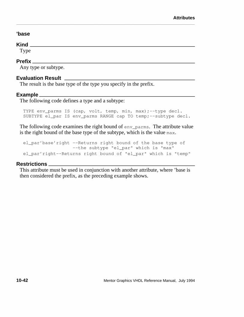
Attributes________________________________________________________________________________________________________________________
’base
KindType
PrefixAny type or subtype.
Evaluation Result The result is the base type of the type you specify in the prefix.
ExampleThe following code defines a type and a subtype:
TYPE env_parms IS (cap, volt, temp, min, max);--type decl.SUBTYPE el_par IS env_parms RANGE cap TO temp;--subtype decl.
The following code examines the right bound of env_parms. The attribute valueis the right bound of the base type of the subtype, which is the value max.
el_par’base’right --Returns right bound of the base type of --the subtype "el_par" which is "max"el_par’right--Returns right bound of "el_par" which is "temp"
RestrictionsThis attribute must be used in conjunction with another attribute, where ’base isthen considered the prefix, as the preceding example shows.
10-42 Mentor Graphics VHDL Reference Manual, July 1994

Attributes________________________________________________________________________________________________________________________
’high
KindValue
PrefixAny scalar type or subtype.
Result TypeThe same type as the prefix type.
Evaluation Result The result is the upper bound of the specified prefix type.
ExampleThe following code defines address_range:TYPE address_range IS RANGE 0 TO 16;
The following code returns the value "16", which is the upper bound ofaddress_range:address_range’high
The following code defines down_address_range:TYPE down_address_range IS RANGE 10 DOWNTO 1;
The following code returns the value "10", which is the upper bound ofdown_address_rang:.down_address_range’high
Mentor Graphics VHDL Reference Manual, July 1994 10-43

Attributes________________________________________________________________________________________________________________________
’left
KindValue
PrefixAny scalar type or subtype.
Result TypeThe same type as the prefix type.
Evaluation Result The result is the left bound of the specified prefix type.
ExampleThe following code defines address_range:
TYPE address_range IS RANGE 0 TO 31;
The following code returns the value "0", which is the left bound ofaddress_range:
address_range’left
10-44 Mentor Graphics VHDL Reference Manual, July 1994

Attributes________________________________________________________________________________________________________________________
’leftof(x)
KindFunction
PrefixAny enumeration, integer, physical type or subtype.
ParameterThe value for the parameter (x) must be of the same base as the specified prefix.
Result TypeThe result type corresponds to the base type of the specified prefix.
Evaluation Result The evaluation result is the value that is to the left of the specified parameter.
ExampleThe following code defines the enumerated type color: TYPE color IS (red, yellow, green, flash);
The following code returns the value yellow, which is the value at the position tothe left of the position specified by the parameter green.color’leftof(green)
RestrictionsThe specified parameter (x) cannot be equal to the left bound of the base type.An error occurs if you try to examine an item to the left of the left-most item.
Mentor Graphics VHDL Reference Manual, July 1994 10-45

Attributes________________________________________________________________________________________________________________________
’low
KindValue
PrefixAny scalar type or subtype.
Result TypeThe same type as the prefix type.
Evaluation Result The result is the lower bound of the specified prefix type.
ExampleThe following code defines address_range:
TYPE address_range IS RANGE 16 DOWNTO 0;
The following code returns the value "0", which is the lower bound ofaddress_range:
address_range’low
10-46 Mentor Graphics VHDL Reference Manual, July 1994

Attributes________________________________________________________________________________________________________________________
’pos(x)
KindFunction
PrefixAny enumeration, integer, physical type, or subtype.
ParameterThe value for the parameter (x) must be of the same base as the specified prefix.
Result Typeuniversal_integer.
Evaluation Result The result is the position number of the item specified by the parameter (x).
Example The following code defines the enumerated type color:TYPE color IS (red, yellow, green, flash);
The following returns the integer 2, which is the value of the position of green:color’pos(green)
The position number for an enumerated type is always referenced from zero andincreases left to right. From the previous example:
Value: red yellow green flashPosition: 0 1 2 3
Mentor Graphics VHDL Reference Manual, July 1994 10-47

Attributes________________________________________________________________________________________________________________________
’pred(x)
KindFunction
PrefixAny enumeration, integer, physical type, or subtype.
ParameterThe value for the parameter (x) must be of the same base as the specified prefix.
Result TypeThe result type corresponds to the base type of the specified prefix.
Evaluation Result The result returns the value that is located one position less than the specifiedparameter (x).
ExampleThe following code shows the definition of num: TYPE num IS RANGE -3 TO 17;
The following code returns the value "9", which is the value at one position lessthan the position specified by the parameter (10): num’pred(10)
RestrictionsYou cannot specify a parameter that is equal to the lower bound of the base type.Using the previous example, an error occurs if you specify the following code:num’pred(-3)
The previous example shows an error condition, since there is no value in theposition one lower than "-3".
10-48 Mentor Graphics VHDL Reference Manual, July 1994

Attributes________________________________________________________________________________________________________________________
’right
KindValue
PrefixAny scalar type or subtype.
Result TypeThe same type as the prefix type.
Evaluation Result The result is the right bound of the specified prefix type.
ExampleThe following example shows the definition of address_range:
TYPE address_range IS RANGE 1 TO 32;
The following code returns the value "32", which is the right bound ofaddress_range:
address_range’right
Mentor Graphics VHDL Reference Manual, July 1994 10-49

Attributes________________________________________________________________________________________________________________________
’rightof(x)
KindFunction
PrefixAny enumeration, integer, physical type, or subtype.
ParameterThe value for the parameter (x) must be of the same base as the specified prefix.
Result TypeThe result type corresponds to the base type of the specified prefix.
Evaluation Result The evaluation result is the value that is to the right of the specified parameter.
ExampleThe following code defines color:
TYPE color IS (red, yellow, green, flash);
The following code returns the value flash, which is the value at the position tothe right of the position specified by the parameter green: color’rightof(green)
RestrictionsThe specified parameter (x) cannot be equal to the right bound of the base type.An error occurs if you try to examine an item to the right of the right-most item.
10-50 Mentor Graphics VHDL Reference Manual, July 1994

Attributes________________________________________________________________________________________________________________________
’succ(x)
KindFunction
PrefixAny enumeration, integer, physical type, or subtype.
ParameterThe value for the parameter (x) must be of the same base as the specified prefix.
Result TypeThe result type corresponds to the base type of the specified prefix.
Evaluation Result The result returns the value that is located one position greater than the specifiedparameter (x).
ExampleThe following code defines num:TYPE num IS RANGE -3 TO 25;
The following code returns the value "-1", which is the value at one positiongreater than the position specified by the parameter "-2".num’succ(-2)
RestrictionsYou cannot specify a parameter that is equal to the upper bound of the base type.Using the previous example, an error occurs if you specify the following code: num’pred(25)
The previous example shows an error condition, since there is no value in theposition one greater than "25".
Mentor Graphics VHDL Reference Manual, July 1994 10-51

Attributes________________________________________________________________________________________________________________________
’val(x)
KindFunction
PrefixAny enumeration, integer, physical type, or subtype.
ParameterAny integer type expression.
Result TypeThe result type corresponds to the base type of the specified prefix.
Evaluation Result The result returns the value of the position number specified by parameter (x).
Example The following code defines the enumeration type color: TYPE color IS (red, yellow, green, flash);
The following code returns the value green, which is the value at position "2"specified by the parameter "2": color’val(2)
The position number for an enumerated type is always referenced from zero andincreases left to right. From the previous example:
Value: red yellow green flashPosition: 0 1 2 3
10-52 Mentor Graphics VHDL Reference Manual, July 1994

Attributes________________________________________________________________________________________________________________________
User-Defined AttributesUser-defined attributes allow you to add to design descriptions incidental orsupplemental information that cannot be described using other VHDL constructs.For example, you might want to back-annotate such physical characteristics ascomponent placement, signal-to-pin assignments, or output and inputcapacitances to a design.
You employ user-defined attributes through the following VHDL constructs:
● Attribute declaration names and sets the type of a user-defined attribute
● Attribute specification, which associates a user-defined attribute with one ormore members of a particular "entity class," such as an entity declaration,procedure, signal, or component. The specification also defines the value ofan attribute.
● Attribute name gives you access to a user-defined attribute, in the same wayas for predefined attributes.
The attribute declaration and attribute specification constructs are described onpages 10-54 and 10-55, respectively; the attribute name construct is described onpage 10-3.
Mentor Graphics VHDL Reference Manual, July 1994 10-53

Attributes________________________________________________________________________________________________________________________
attribute_declarationAn attribute declaration defines a user-defined attribute. Attribute declarationsare not allowed for predefined attributes.
Construct Placementdeclaration, package_declarative_item, process_declarative_item,subprogram_declarative_item
Syntax
attribute_declaration ::= attribute identifier : type_mark
Definitions
■ identifierThis is the simple name of the attribute.
■ type_markDenotes a subtype that is neither an access type nor a file type. The subtypedoes not need to be constrained.
DescriptionBefore a user-defined attribute can be used in a VHDL description, it has to bedeclared. The declaration establishes the name of the attribute and the type of theattribute. Once declared, the attribute can be used (through an attributespecification) anywhere within the scope of the region in which it was declared.
Examples
ATTRIBUTE technology : STRING;
ATTRIBUTE part_count : INTEGER;
TYPE capacitance IS RANGE 0.0 TO 1.0E-6;ATTRIBUTE output_cap : capacitance;
TYPE coordinates IS RECORD Xvalue,Yvalue : integer; -- type declaration
END RECORD;ATTRIBUTE component_location : coordinates; -- attribute decl.
10-54 Mentor Graphics VHDL Reference Manual, July 1994

Attributes________________________________________________________________________________________________________________________
attribute_specificationAn attribute specification associates a user-defined attribute with one or moremembers of an "entity class" within a VHDL description. It also defines thevalue of that attribute for those members. Attribute specifications are notallowed for predefined attributes.
Construct Placementconfiguration_declarative_part, entity_declarative_item,package_declarative_item, process_declarative_item,subprogram_declarative_item
Syntax
attribute_specification ::= attribute attribute_designator of entity_specification is expression ;
attribute_designator ::= attribute_simple_name
entity_specification ::= entity_name_list : entity_class
entity_name_list ::= entity_designator { , entity_designator } | others | all
entity_class ::= entity | architecture | configuration | procedure | function | package | type | subtype | constant | signal | variable | component | label
entity_designator ::= simple_name | operator_symbol
Mentor Graphics VHDL Reference Manual, July 1994 10-55

Attributes________________________________________________________________________________________________________________________
Definitions
■ attribute_designatorThis denotes a previously declared attribute.
■ entity_specificationThis specifies the items that the attribute specification applies to andidentifies the entity class of those items.
■ entity_name_listThis identifies the items that will inherit the attribute.
DescriptionAn attribute specification associates a previously declared user-defined attributewith particular members of one of the following entity classes:
● Entities
● Architectures
● Configurations
● Subprograms
● Packages
● Types
● Subtypes
● Constants
● Signals
● Variables
● Components
● Labels
All members that you designate in the entity name list inherit the attribute,provided that the classes of those members are the same as the specified entityclass; it is an error if the classes do not match. Here are some examples ofattribute specifications:ATTRIBUTE technology OF rd_wrt_cont5 : CONFIGURATION IS ecl
ATTRIBUTE part_count OF rd_wrt_cont5 : CONFIGURATION IS 35
ATTRIBUTE output_cap OF strobe1 : SIGNAL IS 5.0E-12
ATTRIBUTE component_location OF U210 : LABEL is (110,450)
A given attribute must not be associated more than once with a particularentity-class member. Likewise, two different attributes with the same simple
10-56 Mentor Graphics VHDL Reference Manual, July 1994

Attributes________________________________________________________________________________________________________________________
name must not be associated with the same entity-class member.
If you use others in the entity name list, the specification applies, within theimmediately enclosing declarative region, to members of the specified entityclass whose names have not appeared in the name list of a previous attributespecification.
If you use all in the entity name list, the specification applies to all members ofthe specified entity class within the immediately enclosing declarative region.
An attribute specification that uses either others or all for a given entity classmust be not used again for that entity class within a given declarative region.
To supply a particular value that you want to associate with the designatedentity-class members, you use the expression portion of the attributespecification. User-defined attributes must be constants. The type of theexpression must be the same as (or must implicitly convert to) the type specifiedin the corresponding attribute declaration. The information supplied through auser-defined attribute is local only and cannot be passed from one element of adescription to another.
If you apply an attribute specification to a design unit (entity declaration,architecture body, configuration, package declaration, or package body) it mustappear immediately within the declarative part of the design unit. For otherentity-class members (procedures, types, subtypes, objects, components, andlabels), the attribute specification must appear within the declarative part wherethe individual members are declared.
Mentor Graphics VHDL Reference Manual, July 1994 10-57

Signals________________________________________________________________________________________________________________________
Section 11Signals
This section discusses the subject of signals and how to use them. A signal is anobject that you can assign projected future values to and has a history and a timedimension. The following ordered list shows the constructs and topics thissection discusses:
Signal Concepts 11-4Drivers 11-4Guarded Signals 11-5disconnection_specification 11-8Multiple Drivers and Resolution Functions 11-10
signal_declaration 11-14Default Expression 11-15
Signal Assignments 11-16Sequential Signal Assignments 11-16Concurrent Signal Assignments 11-17
Delay Concepts 11-19Delta Delay 11-20
Figure 11-1 shows where signals belong in the overall language and shows thetopics that this section discusses.
Signals are the fundamental design object in VHDL. Signals are the only meansfor interfacing two or more entities, as they provide the channels ofcommunication. You can make the analogy that signals are the equivalent of netsand pins on a schematic sheet. Since a signal is an object, it must be declaredbefore you can use it. A signal declaration takes two forms, as the following listshows:
● Explicitly declare the signal using a signal declaration. You can use the signaldeclaration in an entity declaration, architecture declaration, block statement,or a package declaration.
Mentor Graphics VHDL Reference Manual, July 1994 11-1

Signals________________________________________________________________________________________________________________________
● Declare the signal as a port. You can declare a port in the entity header of anentity declaration, in a parameter in a subprogram specification, or in acomponent declaration. For information on ports, refer to page 8-8.
������������������������������������������������������������������������������������������������������������������������������������������������������������������������������������������������������������������������������������������������������������������������������������������������������������������������������������������������������������������������������������������������������������������������������������������������������������������������������������������������������������������������������������������������������������������������������������������������������������������������������������������������������������������������������������������������������������������������������������������������������������������������������������������������������������������������������������������������������������������������������������������������������������������������������������
Signals
Signal Declaration
SignalsTypes
Configurations
Design Entities
ComponentsAttributes
Packages
Naming, Scope, and Visibility
Lexical Elements
Expressions
Design Units
Subprograms
Declarations
Statements
Signal Assignment
SequentialConcurrent
Signal Concepts
DriversGuarded Signals
Disconnection Specification
Multiple Drivers &Resolution Functions
Figure 11-1. Signals
After declaring a signal, you assign values to it using a sequential or concurrentsignal assignment statement. For example, the following code shows a signal
11-2 Mentor Graphics VHDL Reference Manual, July 1994

Signals________________________________________________________________________________________________________________________
assignment that can be sequential or concurrent, depending on where in yourcode it appears:
enable <= ’0’,’1’ AFTER 5 ns,’0’ AFTER 10ns,’1’ AFTER 30 ns;
In the preceding example, the items to the right of the "<=" are waveformelements. Each of the waveform elements is "held" in a container called a driver.These values are the projected output waveform for the signal.
The signal is the item on the left of the "<=" delimiter, and the simulator creates adriver for this signal, which is a source for the value of a signal. Each time thesignal assignment statement executes, the value of the waveform element isappended to the driver when the time you designate arrives. The driver is theitem that is read by the system to determine the new value for the signal.
A signal may have more than one driver, which means the drivers collectivelydetermine the value of the signal. If this is the case, you must specify whathappens to the signal by specifying a resolution. You accomplish this by using aresolution function.
The signal also contains attribute information. You use signal attributes todetermine information about a signal, such as when the last time an event tookplace or what the last value of the signal was. Some signal attributes are actuallyanother signal, while others return a value. For detailed information on all thepredefined signal attributes, refer to page 10-28. Figure 11-2 shows the conceptof what comprises a signal. This figure shows a signal with two drivers.
Signal
Current Value
Attributes
Driver Driver
Figure 11-2. Composition of a Signal
The following subsections elaborate on the preceding topics, as well as introduceyou to other signal concepts.
Mentor Graphics VHDL Reference Manual, July 1994 11-3

Signals________________________________________________________________________________________________________________________
Signal ConceptsThis subsection discusses the various concepts that apply to signals and their use.The following list shows you the topics that are covered:
● Drivers
● Guarded signals (registers and buses)
● Disconnection specification
● Multiple drivers and resolution functions
Drivers
You use the signal assignment statement to change the value of the projectedoutput waveforms that are in the driver for a signal. You can think of a driver asa container for the projected output waveform that the system creates. The valueof a signal is related to the current values of its drivers. The following exampleshows a signal assignment statement, and is followed by an illustration showinghow the driver determines the value of the signal.
enable <= ’0’,’1’ AFTER 5 ns,’0’ AFTER 10ns,’1’ AFTER 20 ns;
0 5 10 15time (ns)
Driver for "enable"
’0’
’1’
sign
al v
alue
20
A driver contains the projected output waveform for the signal. The projectedoutput waveform contains at least one transaction. A transaction is a signal value
11-4 Mentor Graphics VHDL Reference Manual, July 1994

Signals________________________________________________________________________________________________________________________
and time for the transaction to occur. The transactions from the previousexample consist of the following pairs of items:
Value Time
’0’ 0 ns ’1’ 5 ns’0’ 10 ns ’1’ 20 ns
A signal can have multiple drivers or sources. In this case a resolution function isrequired to resolve the effective value of the signal that has two or more driverscontributing to the signal. For more information about resolution functions, referto page 11-10.
Guarded Signals
A signal guard allows you to control the assigning of signal values. The guard isa Boolean expression that assigns the drivers of the guarded signal a nulltransaction, which turns the driver off when the value of the expression isFALSE. If the value of the guard is TRUE, the signal assignment is made. Youspecify the delay time for the driver to turn off by using a disconnectionspecification. For information on the disconnection specification, refer to page11-8.
The methods for guarding signals is to specify register or bus as the signal kindin a signal declaration. (Refer also to the discussion of concurrent signalassignments on page 6-23.) Here is an example of a signal declaration that usesbus as the signal kind:
SIGNAL data_bus : wired_or bit_vector (0 TO 7) BUS;
Registers and buses are automatically guarded signals. You specify the guardexpression in a block statement. Signals of the kind register, retain the last outputvalue when all drivers are disconnected. Signals of the kind bus, re-evaluate theoutput value when all drivers are disconnected. The following example showsthe difference between the register and bus signal kinds.
This first example shows the declaration of a signal called test of type bit andsignal kind bus. Notice that the signal test has two drivers, so a resolutionfunction (called wired_or) is necessary. The partial code that describes a simple
Mentor Graphics VHDL Reference Manual, July 1994 11-5

Signals________________________________________________________________________________________________________________________
circuit, and the illustration of what the circuit could look like follows.
SIGNAL test : wired_or bit BUS; -- signal declaration
-- partial code descriptions of circuit with signal "test"
test <= GUARDED data AFTER 2 ns WHEN en1 = ’1’ ELSE test AFTER 3 ns;
test <= GUARDED cntrl AFTER 2 ns WHEN en2 = ’1’ ELSE test AFTER 3 ns;
en1 en2
data cntrl
Signal "test"
11-6 Mentor Graphics VHDL Reference Manual, July 1994

Signals________________________________________________________________________________________________________________________
This second example shows the declaration of a signal called test of type bit andsignal kind register. It also shows the use of this signal in a simple circuit. Thepartial code that describes the circuit is the same code as in the previous example,except for the signal kind.
SIGNAL test : wired_or bit REGISTER; -- signal declaration
-- partial code descriptions of circuit with signal "test"
test <= GUARDED data AFTER 2 ns WHEN en1 = ’1’ ELSE test AFTER 3 ns;
test <= GUARDED cntrl AFTER 2 ns WHEN en2 = ’1’ ELSE test AFTER 3 ns;
en1 en2
data cntrl
Signal "test"
guards Signal "test" Value
Mentor Graphics VHDL Reference Manual, July 1994 11-7

Signals________________________________________________________________________________________________________________________
disconnection_specificationYou use the disconnection specification to specify the time delay for turning off adriver of a guarded signal, when the guard is false.
Construct Placementblock_declarative_item, entity_declarative_item, package_declarative_item
Syntax
disconnection_specification ::= disconnect guarded_signal_specification after time_expression ;
guarded_signal_specification ::= guarded_signal_list : type_mark
signal_list ::= signal_name { , signal_name } | others | all
DescriptionThe following list shows the rules for using the disconnection specification:
● When you specify a signal list, each signal name in the list must be a locallystatic name that refers to a guarded signal.
● The time expression must be static and evaluate to a positive value.
● The disconnection specification can apply only to the drivers of one signal. Iftwo or more disconnection specifications apply to the drivers of the samesignal, an error occurs.
There is a disconnection specification for every guarded signal, whether youexplicitly define one or you elect to use the implicit default. The defaultdisconnection specification is generated by the system internally and takes thefollowing form:
DISCONNECT guarded_sig_name: guarded_sig_type AFTER 0 ns;
11-8 Mentor Graphics VHDL Reference Manual, July 1994

Signals________________________________________________________________________________________________________________________
ExampleThe following example shows a possible use of the disconnection specification:
ARCHITECTURE sig_test OF test ISSIGNAL tester : wired_or bit BUS; -- signal declarationsSIGNAL a : bit;DISCONNECT tester : bit AFTER 10 ns; -- discon. spec.
BEGINsig_assign: -- block labelBLOCK (tester = ’1’) -- guard expression SIGNAL z : bit; -- block_declarative_itemBEGIN z <= GUARDED a; -- "z" gets "a" if "test" = ’1’END BLOCK sig_assign;
END sig_test;
Mentor Graphics VHDL Reference Manual, July 1994 11-9

Signals________________________________________________________________________________________________________________________
Multiple Drivers and Resolution Functions
Every signal you define that is the target of a signal assignment has a driver. Ifthe signal has more than one driver (is a target for more than one signalassignment statement), you need to define a resolution function.
The resolution function is a subprogram that defines what single value the signalshould have when there are multiple drivers for that signal. The input parameterto the resolution function is an array that contains all the driver values for thesignal. The resolution function is called every time the signal is active. Forinformation on subprograms (functions and procedures), refer to page 7-1.
For example, you create the signal "test" that has three drivers. The systemcreates an array that contains the value of the drivers as the input to a resolutionfunction.
Assume that signal "test" is of the following my_qsim_state type: TYPE my_qsim_state IS (’X’, ’0’, ’1’, ’Z’);
You then write a resolution function that represents a wired OR function, basedon a driver resolution table for the states ’1’, ’X’, ’0’, and ’Z’. The resolutionfunction returns a resolved value for the signal. Figure 11-3 illustrates thisconcept.
11-10 Mentor Graphics VHDL Reference Manual, July 1994

Signals________________________________________________________________________________________________________________________
en1
data_a
en2
data_b
en3
data_c
data_a data_b data_c
Resolution Function
Code describing a signalwith three drivers(represented at the right):
Array of the threedrivers created:
Array of the threedrivers is the inputparameter to the resolutionfunction:
Signal value is resolved:
Signal test
Figure 11-3. Resolution Function Concept
The following steps show you how to write the description and the resolutionfunction for the example in Figure 11-3.
1. The following architecture body shows the description for the signal testwith three drivers.
ARCHITECTURE data_flow OF tester IS SIGNAL test : wired_or my_qsim_state; SIGNAL data_a, data_b, data_c : my_qsim_state; SIGNAL en1, en2, en3 : bit; BEGIN
test <= data_a AFTER 2 ns WHEN en1 = ’1’ ELSE ’Z’; test <= data_b AFTER 2 ns WHEN en2 = ’1’ ELSE ’Z’; test <= data_c AFTER 2 ns WHEN en3 = ’1’ ELSE ’Z’; END data_flow;
Mentor Graphics VHDL Reference Manual, July 1994 11-11

Signals________________________________________________________________________________________________________________________
2. Table 11-1 shows the driver resolution value for two drivers. To determinethe resolution value, you locate one driver value along the bottom row and theother driver value along the left-hand column. The cross-point indicates theresolution value. To find the resolution of the third driver, you compare yourfirst result to the third driver value.
Table 11-1. Driver Resolution Table
1 1 X X 1
X X X X X
F 0 X X 0 0
Driver Z 1 X 0 Z
ValueH 1 X 0 Z
For example: if en1, en2, and en3 are "1" and if data_a is "X", data_b is"1" and data_c is "0", the resolution value for signal test is "X", because"X" dominates any other driver value.
3. Using Table 11-1 you can write a resolution function similar to the following:
ENTITY tester IS FUNCTION wired_or(driv_array: my_qsim_state_vector) RETURN my_qsim_state IS VARIABLE temp1, temp0, tempz : boolean; BEGIN IF driv_array’length = 0 THEN -- Check if all drivers RETURN ’Z’; -- are disconnected. END IF; -- Loop to check each FOR i IN driv_array’range LOOP -- driver array value. IF driv_array(i) = ’X’ THEN -- Check for ’X’. RETURN ’X’; ELSIF driv_array(i) = ’1’ THEN -- Check for "1". temp1 := true; -- Set temp1 true. ELSIF driv_array(i) = ’0’ THEN -- Check for ’0’. temp0 := true; -- Set temp0 true. ELSE tempz := true; -- Must be ’Z’. END IF; END LOOP;
11-12 Mentor Graphics VHDL Reference Manual, July 1994

Signals________________________________________________________________________________________________________________________
--Check the temporary values (temp1, temp0, and tempz) IF temp1 AND temp0 THEN -- If there are drivers of ’1’ RETURN ’X’; -- and ’0’, return an ’X’, ELSIF temp1 THEN -- otherwise if ’1’ driver, RETURN ’1’; -- return a ’1’, ELSIF temp0 THEN -- otherwise if ’0’ driver, RETURN ’0’; -- return a ’0’, ELSE -- otherwise return ’Z’. RETURN ’Z’; END IF; END wired_or;END tester;
The following list shows the rules that govern the use of the resolution function:
● Every signal of signal kind bus or register must have a resolution function tohandle the disconnection specification.
● If the signal kind is bus, the resolution function must provide a return valuefor the case when all the drivers are disconnected. The previous examplechecks for this using the following code:
IF driv_array’length = ’0’ THEN -- check if all driversRETURN ’Z’; -- are disconnected
END IF;
● There can be only one input parameter to the function. You can use any legalname you wish for this parameter. In the previous example, the namedriv_array is used as the following code shows:
FUNCTION wired_or (driv_array: my_qsim_state_vector)RETURN my_qsim_state IS
. . .
Mentor Graphics VHDL Reference Manual, July 1994 11-13

Signals________________________________________________________________________________________________________________________
signal_declarationA signal declaration declares an object that has a current value, a history, and aprojected value.
Construct Placementblock_declarative_item, entity_declarative_item, object_declaration,package_declarative_item,
Syntax
signal_declaration ::= signal identifier_list : subtype_indication [ signal_kind ] [:= expression] ;
signal_kind ::= register | bus
Definitions
■ identifier_list Lists one or more signal names. Multiple names must be separated bycommas.
■ subtype_indicationIndicates the subtype of the signal(s) and any resolution function orconstraints that apply. The subtype must not be a file type or access type.
■ signal_kindValid entries are bus or register.
■ expressionDefines the initial value of the signal.
DescriptionA signal declaration specifies the simple names, type, kind, and default value ofan object that has a current value, a history, and a projected value.
Using previous signal concepts as a foundation, you can now explore the detailsof signals. One of these details is the signal declaration. Throughout this sectionyou have seen examples of signal declarations. The following list shows what asignal declaration accomplishes:
11-14 Mentor Graphics VHDL Reference Manual, July 1994

Signals________________________________________________________________________________________________________________________
● Assigns names to the signals (identifier_list)
● Defines the resolution function, the type of the signal, and any index or rangeconstraints (subtype_indication)
● Optionally defines the signal to be a bus or register (signal_kind)
● Optionally defines a default expression for the signal
The following examples show some possible signal declarations:
SIGNAL data_in, data_out : bit;--With identifier_list, and --type_mark.SIGNAL add_line : wired_or bit_vector(1 TO 3) BUS; --With --resolution function, type_mark --and signal_kind.SIGNAL enable: bit := ’0’; --With default expression.
The following list shows the rules that govern the signal declaration:
● You cannot declare a signal that is a file type.
● When you specify the signal as being guarded by using the reserved wordsbus or register, you must include a resolution function.
● If the signal has multiple sources, it also must have a resolution function.
Default Expression
The expression construct at the end of the signal declaration is the default valuefor the signal driver at initialization of the simulation and for the times when thesignal is left unconnected. The expression type you use for the default must bethe same type as the signal. For example:
SIGNAL enable: my_qsim_state := ’X’; --Defaults to ’X’ state
If you do not use a default statement, the system assumes a default for the signal.This implicit default is the left-most value of the signal type, determined by thevalue of the predefined signal attribute ’left. The following example shows asignal type declaration, a signal declaration with no default expression specified,and the implicit default the system assumes.
TYPE my_qsim_state IS (’X’, ’0’, ’1’, ’Z’); --Type decl.
Mentor Graphics VHDL Reference Manual, July 1994 11-15

Signals________________________________________________________________________________________________________________________
SIGNAL enable : my_qsim_state; -- declaration with no default
my_qsim_state’left -- system assumes the default
In the previous example, the default value of the signal "enable" is the left-mostvalue of the signal type, which is ’X’.
The default expression for signals differs from the default expression for ports interms of its interpretation in association lists. For a discussion on this topic, referto page 4-31.
Signal AssignmentsAfter you declare a signal, you assign values to it using a sequential or concurrentsignal assignment. The following example shows the form that signal assignmentstatements take:
test_signal <= ’1’ AFTER 25 ns, ’0’ AFTER 30 ns;
The value to the left of the "<=" delimiter is the signal, which is the target of theassignment. The values to the right of the "<=" are the waveform elements.
The following subsections give you an overview of the sequential and concurrentsignal assignments in relation to the previous discussion on signal concepts. Formore detailed information on the sequential signal assignment statement, refer topage 6-46. For more detailed information on the concurrent signal assignmentstatement, refer to page 6-23.
Sequential Signal Assignments
The sequential signal assignment schedules a waveform element to be assigned toa signal’s driver after a time you specify. If you do not specify a time, a value ofzero nanoseconds is used as the delay. A target in a signal assignment that uses azero nanosecond delay does not get updated within the current simulatoriteration; it is updated at the beginning of the next simulator iteration. If youhave several assignments, the signal assignments are evaluated sequentially.Each evaluation schedules an event (a minimum of one iteration later); it does notupdate the signal immediately in the current simulator iteration. For example:
data_out <= t AND d; --Current value a ’0’, new value a ’1’ result <= data_out AND carry_bit;
11-16 Mentor Graphics VHDL Reference Manual, July 1994

Signals________________________________________________________________________________________________________________________
In the preceding example, the value for data_out evaluates first and thenschedules an event to update the signal. (In this example, the current value fordata_out is a ’0’, and the current evaluation has scheduled data_out to beupdated to a ’1’.) The next sequential signal assignment statement then executesand schedules an event for signal result. The evaluation of the result signaluses the value for data_out within the current iteration, which in this example isa ’0’. Based on the evaluation in the current iteration, a new value is scheduledfor signal result.
The evaluation of the waveform elements determines the future behavior of thedrivers for the target you specify. During the evaluation of a waveform element,the following action occurs:
● Assign the target a specific value at a specified time.
● Specify that the target is turned off after a specified time.
If you specify time expressions in the waveform element, these delay times mustuse the time units from package "standard". If you do not specify a timeexpression, the default is zero nanoseconds. The following examples showpossible sequential signal assignments from within portions of code:
clk <= ’1’ AFTER 100 ns; --clk gets 1 after time specifiedresult <= a OR b OR c; --result gets expression in 0 nswire <= TRANSPORT 5 AFTER 25 ns; --Trans. delay after timeline <= TRANSPORT 100; --Transport delay at 0 ns
Concurrent Signal Assignments
The concurrent signal assignment statement is an equivalent process statementthat the system generates to assign values to signals. If you have severalassignments, the signal assignments are made all at the same time step(concurrently). For example:
data_out <= t AND d;result <= data_out AND carry_bit;
In the preceding example, the value for data_out evaluates during the same timestep as the value for result evaluates. Therefore, the evaluation for resultuses the new value of data_out determined by the t AND d evaluation. Morethan one iteration is required within a given time step to evaluate and assign newvalues to the targets of concurrent statements.
Mentor Graphics VHDL Reference Manual, July 1994 11-17

Signals________________________________________________________________________________________________________________________
The concurrent signal assignment can take two forms:
● Conditional signal assignment
● Selected signal assignment
The conditional signal assignment form of the concurrent signal assignmentstatement is an equivalent process statement that the system generates thatassigns values to signals using an "if" statement format. You do not actually seethis format. It is created internally when you use the syntax the followingexample shows:
bus_test : BLOCK SIGNAL test, data_a, data_b : wired_or my_qsim_state_vector (0 TO 7); SIGNAL en1, en2 : bit;BEGIN -- the following code shows cond. signal assignments
test <= data_a AFTER 2 ns WHEN en1 = ’1’ ELSE data_b AFTER 2 ns; END BLOCK bus_test;
The selected signal assignment form of the concurrent signal assignmentstatement is an equivalent process statement generated by the system. Theconcurrent signal assignment statement assigns values to signals using a casestatement format. You do not actually see this format. It is created internallywhen you use the format the following example shows:
11-18 Mentor Graphics VHDL Reference Manual, July 1994

Signals________________________________________________________________________________________________________________________
bus_drive: BLOCK SIGNAL test, data_a, data_b : my_qsim_state_vector (0 TO 7); SIGNAL en1 : bit;
BEGIN -- the following code shows selected sig. assign. WITH en1 SELECT test <= data_a WHEN ’0’, data_b WHEN ’1’;
END BLOCK bus_drive;
For more information on concurrent signal assignments, refer to page 6-23.
Delay ConceptsIn each of the three forms of signal assignments, you can specify two models torepresent delay:
● Transport delay
● Inertial delay
You use the reserved word transport to specify that the delay associated with thefirst waveform element is a transport delay. Transport delay indicates that anypulse is transmitted to the signal name you specify, with no regard to how shortthe pulse width or duration. This pulse waveform exhibits a frequency responsethat is nearly infinite, which is characteristic of items such as wires and metalpaths.
You typically use transport delay to model pure delay, without any considerationof the real, physical behavior, at high levels of abstraction. All input changespass to the output after the delay time you specify.
If you do not use the reserved word transport, the default is inertial delay.Inertial delay applied to a waveform indicates that pulses with a width shorterthan the delay time you specify in the waveform element are not transmitted tothe signal name you specify. This type of delay is characteristic of switchingcircuits, because of the effect of filtering out pulses that are not required.
You typically use inertial delay to model real, physical behavior where a rise orfall time of the output is equivalent to the delay time. The output begins to reactto the input change. However, the new value is not recognized until after thedelay time.
Mentor Graphics VHDL Reference Manual, July 1994 11-19

Signals________________________________________________________________________________________________________________________
The following example shows two signal assignments: one with transport delay,the other with the default inertial delay. Figure 11-4 shows the differencebetween the two waveforms.
a_tran <= TRANSPORT wave AFTER 10 ns;
a_iner <= wave AFTER 10 ns;
wave
a_tran
a_iner
0 5 10 20time (ns)2515 30 40 4535 50
Figure 11-4. Inertial and Transport Delay
In the preceding example, the 5 ns pulse (circled area) on wave is assigned to thesignal a_tran, which has transport delay. The 5 ns pulse on wave is not assignedto a_iner because this signal has inertial delay, which means any pulse widthsmaller than 10 ns is not assigned to a_iner.
Delta Delay
Another delay concept that is important to understand is the concept of deltadelay. Delta delay is an infinitesimal value of time that is greater than zero. Youcan think of delta delay as one simulation iteration. The concept of delta delay isnecessary when you make a signal assignment with no delay expression. Forexample:
pure_delay <= a + b;
11-20 Mentor Graphics VHDL Reference Manual, July 1994

Signals________________________________________________________________________________________________________________________
The default delay in the preceding example is 0 ns. The preceding example canbe rewritten as follows:
pure_delay <= a + b AFTER 0 ns;
However, nothing in the simulation environment happens in absolutely zero time.The simulation iteration takes a delta amount of time. To understand this conceptbetter, the following list presents a fundamental overview of the simulationiteration cycle:
● At the beginning of the iteration, any pending events for the given timemature.
● When the event maturity triggers a process that is sensitive to the signalchange, the process is evaluated.
● When a signal assignment that has a 0 ns delay is found, the iterationincrements and the preceding steps repeat. The iterations continue until all the0 ns delay assignments are scheduled.
● The simulation then advances by one simulator time step.
Given the preceding overview, signal assignment values that you define to occurall at one given time are actually scheduled, by the simulator, a delta delay apart.The value the simulator assigns does take effect in the future. However, since thedelta delay is so very small, the scheduled signal assignments with 0 ns delay alltake effect before any signal assignment that has an actual delay value (greaterthan 0).
There can be any number of delta delays for a given time step, and the sum ofthese delays will never equal the next time step.
The remainder of this discussion shows you, through examples, the concept ofdelta delay. Figure 11-5 shows three AND gates, cascaded together. The ANDgates are modeled with 0 ns delay. The input signal "in_1" goes high at thesimulation timestep of 25 ns. Input signals "in_2", "in_3", and "in_4" are allhigh, and have been since the last timestep.
Mentor Graphics VHDL Reference Manual, July 1994 11-21

Signals________________________________________________________________________________________________________________________
a
b
c
in_1
in_2
in_3
in_4
Figure 11-5. Zero Delay Gates
When you trace the signal in the simulator, you see the output signals "a", "b",and "c" all change to a high state at 25 ns. However, if you could trace what thesimulator actually "sees," you would see each of the output signals scheduled onedelta delay (or iteration) apart. Figure 11-6 shows the trace you see at the left,and it shows the trace the simulator "sees" at the right.
time (ns)
25 25
a
b
c
25 ns + 1 iteration 25 ns + 2 iterations25 ns + 3 iterations
Figure 11-6. Comparing Traces
’The delta delay model allows you to model event sequences without taking intoconsideration when the events occur. This concept is called unit-delay modeling.Each delta delay is an equivalent amount of time. However, you should keep inmind, that when you model with signal assignments using the 0 ns default, there
11-22 Mentor Graphics VHDL Reference Manual, July 1994

Signals________________________________________________________________________________________________________________________
actually is a unit-delay.
Figure 11-7 illustrates this concept by using the three AND gates with zero delayas one input to a device and by using a straight signal as the other input. Noticethat the path to "d0" (an edge-triggered input), takes three delta delays, while thepath to "d1" takes one delta delay. This is a potential race condition in a realhardware circuit.
1 Unitdelay
1 Unitdelay
1 Unitdelay
3 Units ofdelay total
d1
d0q>
Figure 11-7. Unit-delay Modeling
Mentor Graphics VHDL Reference Manual, July 1994 11-23

Syntax Summary________________________________________________________________________________________________________________________
Appendix ASyntax Summary
This appendix includes the following information:
● Table A-1 lists the VHDL constructs in alphabetical order and provides a pagenumber for the syntax drawing and a page number where information for eachconstruct can be found in this manual.
● A subsection shows how to use the syntax diagrams.
● All the syntax diagrams for VHDL are listed in alphabetical order.
Table A-1. VHDL Construct Listing
---------------------------------------------------------------------------------------------- Location of Syntax For More Language Construct Diagram Information=======================================================abstract_literalaccess_type_definition actual_designator actual_parameter_partactual_part adding_operatoraggregate alias_declarationallocatorarchitecture_body architecture_declarative_part architecture_statement_part array_type_definition
A-11A-11A-11A-11A-11A-12A-12A-12A-12A-13A-13A-13A-13
1-165-314-317-154-312-232-84-352-148-148-178-185-23
Mentor Graphics VHDL Reference Manual, July 1994 A-1

Syntax Summary________________________________________________________________________________________________________________________
Table A-1. VHDL Construct Listing [continued]---------------------------------------------------------------------------------------------- Location of Syntax For More Language Construct Diagram Information=======================================================assertion_statement association_elementassociation_list attribute_declarationattribute_designatorattribute_name attribute_specificationbasebase_specifierbase_unit_declarationbased_integerbased_literalbinding_indication bit_string_literalbit_valueblock_configurationblock_declarative_item block_declarative_partblock_headerblock_specificationblock_statement block_statement_part case_statement case_statement_alternative choice choicescomponent_configurationcomponent_declaration component_instantiation_statement component_specification
A-14A-14A-14A-14A-14A-15A-15A-15A-15A-16A-16A-16A-16A-16A-17A-17A-18A-19A-19A-19A-20A-20A-20A-21A-21A-21A-21A-22A-22A-22
6-104-314-3110-5410-310-310-551-171-205-151-171-178-291-201-208-398-176-126-128-396-126-136-156-152-82-88-434-366-178-25
A-2 Mentor Graphics VHDL Reference Manual, July 1994

Syntax Summary________________________________________________________________________________________________________________________
Table A-1. VHDL Construct Listing [continued]---------------------------------------------------------------------------------------------- Location of Syntax For More Language Construct Diagram Information=======================================================composite_type_definition concurrent_assertion_statement concurrent_procedure_call concurrent_signal_assignment_statementconcurrent_statement conditioncondition_clauseconditional_signal_assignmentconditional_waveforms configuration_declarationconfiguration_declarative_itemconfiguration_declarative_partconfiguration_itemconfiguration_specification constant_declaration constrained_array_definition constraint context_clausecontext_item decimal_literaldeclaration design_filedesign_unitdesignatordigitdirectiondisconnection_specification discrete_rangeelement_association
A-22A-22A-23A-23A-23A-24A-24A-24A-24A-25A-25A-25A-25A-25A-26A-26A-26A-26A-26A-27A-27A-28A-28A-28A-28A-28A-29A-29A-29
5-226-196-216-236-76-496-496-256-258-358-358-358-398-254-135-234-79-59-51-164-39-39-37-61-55-511-85-232-8
Mentor Graphics VHDL Reference Manual, July 1994 A-3

Syntax Summary________________________________________________________________________________________________________________________
Table A-1. VHDL Construct Listing [continued]---------------------------------------------------------------------------------------------- Location of Syntax For More Language Construct Diagram Information=======================================================element_declarationelement_subtype_definition subtype_indicationentity_aspect entity_classentity_declaration entity_declarative_item entity_declarative_part entity_designatorentity_header entity_name_list entity_specification entity_statement entity_statement_part enumeration_literalenumeration_type_definition exit_statement exponentexpression extended_digit factor file_declaration file_logical_name file_type_definition floating_type_definitionformal_designator formal_parameter_listformal_part full_type_declarationfunction_call
A-29A-29A-65A-30A-31A-32A-32A-33A-33A-33A-33A-33A-34A-34A-34A-34A-34A-34A-35A-35A-36A-36A-36A-36A-36A-37A-37A-37A-37A-37
5-295-294-78-3110-558-48-108-1010-558-610-5510-558-128-125-195-196-281-162-41-172-44-184-185-345-124-317-84-314-47-15
A-4 Mentor Graphics VHDL Reference Manual, July 1994

Syntax Summary________________________________________________________________________________________________________________________
Table A-1. VHDL Construct Listing [continued]---------------------------------------------------------------------------------------------- Location of Syntax For More Language Construct Diagram Information=======================================================generate_statementgeneration_schemegeneric_clause generic_list generic_map_aspect graphic_characterguarded_signal_specificationidentifier identifier_listif_statement incomplete_type_declarationindex_constraintindex_specificationindex_subtype_definitionindexed_nameinstantiation_list integerinteger_type_definitioninterface_constant_declaration interface_declaration interface_list interface_signal_declaration interface_variable_declaration iteration_scheme labelletterlibrary_clauselibrary_unit literal logical_name
A-38A-38A-38A-38A-38A-39A-39A-39A-39A-40A-40A-40A-40A-40A-41A-41A-41A-41A-42A-42A-42A-42A-43A-43A-43A-43A-44A-44A-44A-44
6-306-308-78-78-321-511-81-84-116-344-45-238-395-233-88-251-165-94-244-224-224-264-296-366-31-59-89-31-159-8
Mentor Graphics VHDL Reference Manual, July 1994 A-5

Syntax Summary________________________________________________________________________________________________________________________
Table A-1. VHDL Construct Listing [continued]---------------------------------------------------------------------------------------------- Location of Syntax For More Language Construct Diagram Information=======================================================logical_name_listlogical_operatorloop_statement miscellaneous_operatormode multiplying_operator name next_statement null_statementnumeric_literal object_declaration operator_symboloptionspackage_body package_body_declarative_item package_body_declarative_part package_declaration package_declarative_item package_declarative_part parameter_specification physical_literalphysical_type_definition port_clause port_list port_map_aspect prefix primary primary_unit procedure_call_statement process_declarative_item
A-44A-45A-45A-45A-46A-46A-47A-47A-47A-47A-48A-48A-48A-49A-49A-49A-50A-50A-51A-51A-51A-51A-51A-51A-52A-52A-52A-53A-53A-54
9-82-316-362-184-222-203-36-386-391-154-107-66-239-159-159-159-139-139-136-361-165-158-88-88-323-52-69-36-406-41
A-6 Mentor Graphics VHDL Reference Manual, July 1994

Syntax Summary________________________________________________________________________________________________________________________
Table A-1. VHDL Construct Listing [continued]---------------------------------------------------------------------------------------------- Location of Syntax For More Language Construct Diagram Information=======================================================process_declarative_part process_statement process_statement_part qualified_expression range range_constraintrecord_type_definitionrelation relational_operatorreturn_statement scalar_type_definition secondary_unit secondary_unit_declaration selected_nameselected_signal_assignment selected_waveformssensitivity_clausesensitivity_listsequence_of_statements sequential_statement signsignal_assignment_statement signal_declaration signal_kindsignal_list simple_expression simple_name
A-54A-55A-55A-55A-56A-56A-56A-56A-57A-57A-57A-58A-58A-58A-58A-58A-58A-59A-59A-60A-60A-61A-61A-61A-61A-62A-62
6-416-416-412-105-55-55-292-42-286-445-49-35-153-56-276-276-496-416-156-52-226-4611-1411-1411-82-43-4
Mentor Graphics VHDL Reference Manual, July 1994 A-7

Syntax Summary________________________________________________________________________________________________________________________
Table A-1. VHDL Construct Listing [continued]---------------------------------------------------------------------------------------------- Location of Syntax For More Language Construct Diagram Information=======================================================slice_namespecial_charactersstring_literalsubprogram_body subprogram_declaration subprogram_declarative_item subprogram_declarative_part subprogram_specification subprogram_statement_part subtype_declaration subtype_indication suffix targetterm timeout_clausetype_conversiontype_declarationtype_definition type_mark unconstrained_array_definition use_clause variable_assignment_statement variable_declaration wait_statement waveform waveform_element
A-62A-62A-63A-63A-63A-64A-64A-65A-65A-65A-65A-66A-66A-66A-66A-66A-67A-67A-67A-67A-68A-68A-68A-68A-69A-69
3-91-51-197-107-67-107-107-67-104-74-73-56-462-46-492-124-44-44-75-233-226-484-156-496-466-46
A-8 Mentor Graphics VHDL Reference Manual, July 1994

Syntax Summary________________________________________________________________________________________________________________________
How to Read a Syntax DiagramThe syntax diagram is a visual representation of the rules for constructing andarranging your code. The example in Figure A-1 illustrates all the possibleelements of a syntax diagram:
construct
construct_one example_construct
,
reserved_word
_two construct_three
Figure A-1. Example Syntax Diagram
The syntax diagram is read from left to right by following the arrow directions.The following list describes each element of the syntax diagram:
● Each individual syntax diagram is called a language construct. The name ofthe construct is the left-most item. In Figure A-1, the language construct isnamed "example_construct".
● "example_construct" is composed of three different items. By following thearrows, you can take three different paths as shown in Figure A-2 by Path Aor Path B or Path C.
● In taking Path A, the boxed item "construct_one" is encountered. All boxeditems indicate another language construct, which is defined by anotherindividual syntax diagram.
Mentor Graphics VHDL Reference Manual, July 1994 A-9

Syntax Summary________________________________________________________________________________________________________________________
construct
construct_one example_construct
,
reserved_word
construct_three
Path B
Path C
Path A
_two
Figure A-2. Multiple Syntax Diagram Paths
The loop back in Path A indicates you can use one or more of the languageconstruct "construct_one", separated by a comma. All items in a circle orellipse indicate a terminal. A terminal is what you actually use in the code (areserved word or character).
● In taking Path B, you must use "construct_two", but "construct_three" can beeither used or omitted.
● The italic words give you additional information and do not represent anactual language construct. The words that follow the italics represent anactual language construct.
● In taking Path C, a reserved_word (terminal) must be used.
The complete syntax for VHDL follows. The number under each languageconstruct shows you where to look in this manual for more information.
A-10 Mentor Graphics VHDL Reference Manual, July 1994

Syntax Summary________________________________________________________________________________________________________________________
A ====================================================
decimal_literal abstract_literal
based_literal
1-16
subtype_indicationaccess_type_definition access
5-31
signal
variable
expression actual_designator
_name
_name
open
4-31
parameter_association_list actual_parameter_part
7-15
function
actual_designator actual_part
_name actual_designator ( )
4-31
Mentor Graphics VHDL Reference Manual, July 1994 A-11

Syntax Summary________________________________________________________________________________________________________________________
adding_operator -
&
+
2-23
element_association aggregate
,
( )
2-8
alias_declaration
;
identifier
namesubtype_indication is
:alias
4-35
allocator new subtype_indication
qualified_expression
2-14
A-12 Mentor Graphics VHDL Reference Manual, July 1994

Syntax Summary________________________________________________________________________________________________________________________
entity
architecture
architecturearchitecture_body architecture
architecture_declarative_part
architecture_statement_part
_simple_name
begin
of
end ;
is_name
_simple_name
8-14
block_declarative_item architecture_declarative_part
8-17
concurrent_statement architecture_statement_part
8-18
unconstrained_array_definition array_type_definition
constrained_array_definition
5-23
Mentor Graphics VHDL Reference Manual, July 1994 A-13

Syntax Summary________________________________________________________________________________________________________________________
assertion_statement assert condition
expression severity
report expression
;
6-10
formal_part association_element => actual_part
4-31
association_element association_list
,
4-31
attribute_declaration :
type_mark ;
attribute identifier
10-54
_simple_name attribute_designator attribute
10-3
A-14 Mentor Graphics VHDL Reference Manual, July 1994

Syntax Summary________________________________________________________________________________________________________________________
attribute_name prefix attribute_designator ’
( _expression )static
10-3
attribute_specification attribute
expression
attribute_designator of
is entity_specification ;
10-55
B =====================================================
integer base
1-17
base_specifier
B
O
X
b
o
x
1-20
Mentor Graphics VHDL Reference Manual, July 1994 A-15

Syntax Summary________________________________________________________________________________________________________________________
identifier base_unit_declaration ;
5-15
extended_digit based_integer
_
1-17
based_literal base based_integer #
based_integer . exponent #
1-17
entity_aspect binding_indication generic_map_aspect
port_map_aspect
8-29
base_specifier bit_string_literal "" bit_value
1-20
extended_digit bit_value
_
A-16 Mentor Graphics VHDL Reference Manual, July 1994

Syntax Summary________________________________________________________________________________________________________________________
1-20
block_configuration for block_specification
configuration_item ; use_clause end for
8-39
subprogram_declaration block_declarative_item
subprogram_body
type_declaration
subtype_declaration
constant_declaration
signal_declaration
file_declaration
component_declaration
configuration_specification
disconnection_specification
use_clause
attribute_specification
Mentor Graphics VHDL Reference Manual, July 1994 A-17

Syntax Summary________________________________________________________________________________________________________________________
8-17
block_declarative_item block_declarative_part
6-12
block_header generic_clause
port_map_aspect ; port_clause
generic_map_aspect ;
6-12
block_specification architecture_name
block_statement_label
generate_statement_label
index_specification( )
A-18 Mentor Graphics VHDL Reference Manual, July 1994

Syntax Summary________________________________________________________________________________________________________________________
8-39
block
guard
block_statement _label : block
( )_expression
block_statement_part
begin
end block ; _label
block
block_declarative_partblock_header
6-12
concurrent_statement block_statement_part
6-13
C====================================================
expression case_statement case is
case_statement_alternative end case ;
6-15
Mentor Graphics VHDL Reference Manual, July 1994 A-19

Syntax Summary________________________________________________________________________________________________________________________
choices case_statement_alternative
=> sequence_of_statements
when
6-15
graphic_character ’character_literal ’
1-18
simple_expression choice
others
discrete_range
_simple_name element
2-8
choice choices
|
2-8
component_configuration
use
component_specification
block_configuration ; binding_indication
end for ;
for
8-43
A-20 Mentor Graphics VHDL Reference Manual, July 1994

Syntax Summary________________________________________________________________________________________________________________________
local local
component_declaration component identifier
_generic_clause
;
_port_clause
end component
4-36
instantiation
component
component_instantiation_statement
_name generic_map_aspect
port_map_aspect
_label :
;
6-17
componentcomponent_specification instantiation_list : _name
8-25
composite_type_definition array_type_definition
record_type_definition
5-22
concurrent_assertion_statement : assertion_statement label
6-19
Mentor Graphics VHDL Reference Manual, July 1994 A-21

Syntax Summary________________________________________________________________________________________________________________________
concurrent_procedure_call
procedure_call_statement : label
6-21
concurrent_signal_assignment_statement
: conditional_signal_assignment
selected_signal_assignment
label
6-23
block_statement concurrent_statement
process_statement
concurrent_procedure_call
concurrent_assertion_statement
component_instantiation_statement
generate_statement
concurrent_signal_assignment_statement
6-7
A-22 Mentor Graphics VHDL Reference Manual, July 1994

Syntax Summary________________________________________________________________________________________________________________________
boolean_expression condition
6-49
condition_clause until condition
6-49
conditional_waveforms ;
target conditional_signal_assignment <= options
6-25
when
waveform
waveform
conditional_waveforms
condition else
Mentor Graphics VHDL Reference Manual, July 1994 A-23

Syntax Summary________________________________________________________________________________________________________________________
6-25
configuration_declaration configuration
entity_name is
;
of configuration_simple_name
configuration_declarative_part block_configuration
end configuration_simple_name
8-35
use_clause configuration_declarative_item
attribute_specification
8-35
configuration_declarative_item configuration_declarative_part
8-35
block_configuration configuration_item
component_configuration
8-39
configuration_specification for component_specification
binding_indication use ;
8-25
A-24 Mentor Graphics VHDL Reference Manual, July 1994

Syntax Summary________________________________________________________________________________________________________________________
constant_declaration identifier_list
subtype_indication
:
expression ;
constant
:=
4-13
element
index_constraint constrained_array_definition array
_subtype_indication
of
5-23
range_constraint constraint
index_constraint
4-7
context_item context_clause
9-5
library_clause
use_clause
context_item
9-5
Mentor Graphics VHDL Reference Manual, July 1994 A-25

Syntax Summary________________________________________________________________________________________________________________________
D====================================================
decimal_literal integer . integer exponent
1-16
type_declaration declaration
subtype_declaration
object_declaration
file_declaration
interface_declaration
component_declaration
entity_declaration
subprogram_declaration
package_declaration
alias_declaration
attribute_declaration
configuration_declaration
4-3
A-26 Mentor Graphics VHDL Reference Manual, July 1994

Syntax Summary________________________________________________________________________________________________________________________
design_unit design_file
9-3
context_clause library_unit design_unit
9-3
identifier designator
operator_symbol
7-6
digit
0 1 2 3 4 5 6 7 8 9
1-5
direction
downto
to
5-5
Mentor Graphics VHDL Reference Manual, July 1994 A-27

Syntax Summary________________________________________________________________________________________________________________________
time
guarded
disconnection_specification
disconnect _signal_specification
after _expression ;
11-8
discrete _subtype_indication discrete_range
range
5-23
E====================================================
choices element_association => expression
2-8
: identifier_list
;
element_declaration
element_subtype_definition
5-29
subtype_indication element_subtype_definition
5-29
A-28 Mentor Graphics VHDL Reference Manual, July 1994

Syntax Summary________________________________________________________________________________________________________________________
entity
architecture
_name entityentity_aspect
( )_identifier
configuration
open
configuration_identifier
8-31
Mentor Graphics VHDL Reference Manual, July 1994 A-29

Syntax Summary________________________________________________________________________________________________________________________
entity_class entity
procedure
type
signal
label
architecture
function
subtype
variable
package
constant
component
configuration
10-55
A-30 Mentor Graphics VHDL Reference Manual, July 1994

Syntax Summary________________________________________________________________________________________________________________________
entity
entityentity_declaration entity entity_header
entity_declarative_part entity_statement_part
_simple_name end
is
;
begin
_simple_name
8-4
subprogram_declaration entity_declarative_item
subprogram_body
type_declaration
subtype_declaration
constant_declaration
signal_declaration
file_declaration
disconnection_specification
use_clause
attribute_specification
8-10
Mentor Graphics VHDL Reference Manual, July 1994 A-31

Syntax Summary________________________________________________________________________________________________________________________
entity_declarative_item entity_declarative_part
8-10
simple_name entity_designator
operator_symbol
10-55
formal formal_generic_clause entity_header _port_clause
8-6
entity_designator entity_name_list
,
others
all
10-55
entity_specification entity_name_list : entity_class
10-55
A-32 Mentor Graphics VHDL Reference Manual, July 1994

Syntax Summary________________________________________________________________________________________________________________________
passive
passive
concurrent_assertion_statement entity_statement
_concurrent_procedure_call
_process_statement
8-12
entity_statement entity_statement_part
8-12
identifier enumeration_literal
character_literal
5-19
enumeration_literal enumeration_type_definition
,
( )
5-19
loopexit _label exit_statement when condition ;
6-28
exponent integer +E
e -
1-16
Mentor Graphics VHDL Reference Manual, July 1994 A-33

Syntax Summary________________________________________________________________________________________________________________________
and relation expression relation
or relation
xor relation
nand relation
nor relation
2-4
extended_digit digit
A B C D E F
a b c d e f
1-17
A-34 Mentor Graphics VHDL Reference Manual, July 1994

Syntax Summary________________________________________________________________________________________________________________________
F====================================================
factor
not
primary
primary
abs
primary primary **
2-4
file_declaration identifier :file subtype_indication
is mode file_logical_name ;
4-18
stringfile_logical_name _expression
4-18
file_type_definition offile type_mark
5-34
floating_type_definition range_constraint
5-12
Mentor Graphics VHDL Reference Manual, July 1994 A-35

Syntax Summary________________________________________________________________________________________________________________________
generic
port
parameter
_name
_name
_name
formal_designator
4-31
parameter_interface_list formal_parameter_list
7-8
function
formal_designator formal_part
_name formal_designator ( )
4-31
identifier
type_definition is ;
full_type_declaration type
4-4
function _name
actual_parameter_part ( )
function_call
7-15
A-36 Mentor Graphics VHDL Reference Manual, July 1994

Syntax Summary________________________________________________________________________________________________________________________
G====================================================
generate_statement
generate
; end generate
generate _label : generation_scheme
concurrent_statement
generate _label
6-30
generation_scheme for generate _parameter_specification
condition if
6-30
generic_list ( )generic_clause generic ;
8-7
interface_constant_declaration generic_list
;
8-7
generic
generic_map_aspect generic map
_association_list ( )
8-32
Mentor Graphics VHDL Reference Manual, July 1994 A-37

Syntax Summary________________________________________________________________________________________________________________________
letter graphic_character
digit
special_characters
1-5
guarded _signal_list
type_mark :
guarded_signal_specification
11-8
I====================================================
letter identifier
digit
letter _
1-8
identifier identifier_list
,
4-11
A-38 Mentor Graphics VHDL Reference Manual, July 1994

Syntax Summary________________________________________________________________________________________________________________________
condition
sequence_of_statements
if
;
if_statement then
elsif condition sequence_of_statements then
else end if
sequence_of_statements
6-34
incomplete_type_declaration ;identifiertype
4-4
discrete_range index_constraint
,
( )
5-23
discrete_range index_specification
_expressionstatic
8-39
index_subtype_definition range <> type_mark
5-23
Mentor Graphics VHDL Reference Manual, July 1994 A-39

Syntax Summary________________________________________________________________________________________________________________________
expression indexed_name
,
( ) prefix
3-8
instantiation _label instantiation_list
,
others
all
8-25
integer
_
digit
1-16
integer_type_definition range_constraint
5-9
static
interface_constant_declaration constant identifier_list
subtype_indication : in := _expression
A-40 Mentor Graphics VHDL Reference Manual, July 1994

Syntax Summary________________________________________________________________________________________________________________________
4-24
interface_constant_declaration interface_declaration
interface_signal_declaration
interface_variable_declaration
4-22
interface_list
;
interface_declaration
4-22
static
interface_signal_declaration signal identifier_list :
mode subtype_indication bus
_expression :=
4-26
static
interface_variable_declaration variable identifier_list :
mode subtype_indication _expression :=
4-29
Mentor Graphics VHDL Reference Manual, July 1994 A-41

Syntax Summary________________________________________________________________________________________________________________________
loop
iteration_scheme
for
condition
_parameter_specification
while
6-36
L====================================================
identifier label
6-3
letter
A B C X Y Z
a b c x y z
1-5
logical_name_list library_clause library ;
9-8
primary_unit
secondary_unit
library_unit
9-3
A-42 Mentor Graphics VHDL Reference Manual, July 1994

Syntax Summary________________________________________________________________________________________________________________________
numeric_literal literal
enumeration_literal
string_literal
bit_string_literal
null
1-15
identifier logical_name
9-8
logical_name_list logical_name
,
9-8
logical_operator and
or
nor
xor
nand
2-31
Mentor Graphics VHDL Reference Manual, July 1994 A-43

Syntax Summary________________________________________________________________________________________________________________________
loop
loop
loop_statement _label : iteration_scheme loop
sequence_of_statements end loop _label ;
6-36
M====================================================
miscellaneous_operator **
abs
not
2-18
mode in
out
linkage
out
buffer
4-22
A-44 Mentor Graphics VHDL Reference Manual, July 1994

Syntax Summary________________________________________________________________________________________________________________________
multiplying_operator
*
rem
/
mod
2-20
Mentor Graphics VHDL Reference Manual, July 1994 A-45

Syntax Summary________________________________________________________________________________________________________________________
N====================================================
simple_name name
operator_symbol
selected_name
indexed_name
slice_name
attribute_name
3-3
loop ;next_statement _label next condition when
6-38
null_statement null ;
6-39
numeric_literal abstract_literal
physical_literal
1-15
A-46 Mentor Graphics VHDL Reference Manual, July 1994

Syntax Summary________________________________________________________________________________________________________________________
O====================================================
constant_declaration object_declaration
signal_declaration
variable_declaration
4-10
operator_symbol string_literal
7-6
options guarded transport
6-23
Mentor Graphics VHDL Reference Manual, July 1994 A-47

Syntax Summary________________________________________________________________________________________________________________________
P====================================================
package
package
package_body package _simple_name
package_body_declarative_part
_simple_name
body is
end
;
9-15
subprogram_declaration package_body_declarative_item
subprogram_body
type_declaration
subtype_declaration
constant_declaration
file_declaration
use_clause
alias_declaration
9-15
package_body_declarative_item package_body_declarative_part
9-15
A-48 Mentor Graphics VHDL Reference Manual, July 1994

Syntax Summary________________________________________________________________________________________________________________________
package
packagepackage_declaration package
package_declarative_part _simple_name
is
end ;
_simple_name
9-13
subprogram_declaration package_declarative_item
component_declaration
type_declaration
subtype_declaration
constant_declaration
signal_declaration
file_declaration
disconnection_specification
use_clause
attribute_declaration
attribute_specification
alias_declaration
9-13
Mentor Graphics VHDL Reference Manual, July 1994 A-49

Syntax Summary________________________________________________________________________________________________________________________
package_declarative_item package_declarative_part
9-13
parameter_specification identifier discrete_range in
6-36
unit _name physical_literal abstract_literal
1-16
end
secondary_unit_declaration
units range_constraint physical_type_definition
base_unit_declaration
units
5-15
port_list ( )port_clause port ;
8-8
interface_signal_declaration port_list
;
8-8
A-50 Mentor Graphics VHDL Reference Manual, July 1994

Syntax Summary________________________________________________________________________________________________________________________
port
port_map_aspect port map
_association_list ( )
8-32
name prefix
function_call
3-5
name primary
literal
aggregate
function_call
qualified_expression
type_conversion
expression ( )
allocator
2-6
Mentor Graphics VHDL Reference Manual, July 1994 A-51

Syntax Summary________________________________________________________________________________________________________________________
entity_declaration
package_declaration
primary_unit
configuration_declaration
9-3
procedure_name
actual_parameter_part ( )
procedure_call_statement
;
6-40
A-52 Mentor Graphics VHDL Reference Manual, July 1994

Syntax Summary________________________________________________________________________________________________________________________
subprogram_declaration process_declarative_item
subprogram_body
type_declaration
subtype_declaration
constant_declaration
variable_declaration
file_declaration
use_clause
alias_declaration
attribute_declaration
attribute_specification
6-41
process_declarative_item process_declarative_part
6-41
Mentor Graphics VHDL Reference Manual, July 1994 A-53

Syntax Summary________________________________________________________________________________________________________________________
process
process
process_statement _label :
process ( ) sensitivity_list
process_declarative_part process_statement_part begin
end _label ;process
6-41
sequential_statement process_statement_part
6-41
Q====================================================
type_mark qualified_expression
type_mark
expression
aggregate
( )’
’
2-10
A-54 Mentor Graphics VHDL Reference Manual, July 1994

Syntax Summary________________________________________________________________________________________________________________________
R====================================================
rangerange _attribute_name
direction simple_expression simple_expression
5-5
range range_constraint range
5-5
element_declaration record_type_definition endrecord record
5-29
relational_operator
simple_expression
simple_expression
relation
2-4
Mentor Graphics VHDL Reference Manual, July 1994 A-55

Syntax Summary________________________________________________________________________________________________________________________
relational_operator =
/ =
<=
>
>=
<
same
2-28
return_statement return expression ;
6-44
S====================================================
enumeration_type_definition scalar_type_definition
integer_type_definition
floating_type_definition
physical_type_definition
5-4
A-56 Mentor Graphics VHDL Reference Manual, July 1994

Syntax Summary________________________________________________________________________________________________________________________
architecture_body
package_body
secondary_unit
9-3
secondary_unit_declaration identifier physical_literal = ;
5-15
selected_name prefix suffix .
3-5
selected_signal_assignment with expression
target options ;
select
<= selected_waveforms
6-27
when waveform selected_waveforms choices
,
6-27
sensitivity_list sensitivity_clause on
6-49
Mentor Graphics VHDL Reference Manual, July 1994 A-57

Syntax Summary________________________________________________________________________________________________________________________
signal _name sensitivity_list
,
6-41
sequential_statement sequence_of_statements
6-15
A-58 Mentor Graphics VHDL Reference Manual, July 1994

Syntax Summary________________________________________________________________________________________________________________________
wait_statement sequential_statement
assertion_statement
signal_assignment_statement
variable_assignment_statement
procedure_call_statement
if_statement
case_statement
loop_statement
next_statement
exit_statement
return_statement
null_statement
6-5
sign +
-
2-22
Mentor Graphics VHDL Reference Manual, July 1994 A-59

Syntax Summary________________________________________________________________________________________________________________________
signal_assignment_statement target transport
;
<=
waveform
6-46
signal_declaration identifier_list subtype_indication :
signal_kind ;
signal
:= expression
11-14
register
bus
signal_kind
11-14
signal_name signal_list
,
others
all
11-8
A-60 Mentor Graphics VHDL Reference Manual, July 1994

Syntax Summary________________________________________________________________________________________________________________________
term
sign simple_expression term
adding_operator
2-4
simple_name identifier
3-4
discrete_range slice_name ( ) prefix
3-9
# &’ ( ) *+
,_ .
/
:;<
=
>
-
|$ %
@
?[ ]\^
‘ { }
~ "
!
special_characters
1-5
Mentor Graphics VHDL Reference Manual, July 1994 A-61

Syntax Summary________________________________________________________________________________________________________________________
graphic_character "string_literal "
1-19
subprogram_body subprogram_specification
subprogram_declarative_part
subprogram_statement_part
designator
end
is
;
begin
7-10
subprogram_declaration ; subprogram_specification
7-6
A-62 Mentor Graphics VHDL Reference Manual, July 1994

Syntax Summary________________________________________________________________________________________________________________________
subprogram_declaration subprogram_declarative_item
subprogram_body
type_declaration
subtype_declaration
constant_declaration
variable_declaration
file_declaration
use_clause
alias_declaration
attribute_declaration
attribute_specification
7-10
subprogram_declarative_item subprogram_declarative_part
7-10
Mentor Graphics VHDL Reference Manual, July 1994 A-63

Syntax Summary________________________________________________________________________________________________________________________
formal_parameter_list ( )
formal_parameter_list ( )
subprogram_specification procedure
function designator
return type_mark
identifier
7-6
sequential_statement subprogram_statement_part
7-10
subtype_declaration subtype identifier is
subtype_indication ;
4-7
type_mark subtype_indication _name
constraint
resolution_function
4-7
A-64 Mentor Graphics VHDL Reference Manual, July 1994

Syntax Summary________________________________________________________________________________________________________________________
simple_name suffix
all
character_literal
operator_symbol
3-5
T====================================================
name target
aggregate
6-46
multiplying_operator factor factor term
2-4
timetimeout_clause for _expression
6-49
expression ( ) type_mark type_conversion
2-12
Mentor Graphics VHDL Reference Manual, July 1994 A-65

Syntax Summary________________________________________________________________________________________________________________________
type_declaration full_type_declaration
incomplete_type_declaration
4-4
scalar_type_definition type_definition
file_type_definition
access_type_definition
composite_type_definition
4-4
type
subtype
_name type_mark
_name
4-7
U====================================================
index_subtype_definition (
unconstrained_array_definition
array
_subtype_indication of
,
)
element
5-23
A-66 Mentor Graphics VHDL Reference Manual, July 1994

Syntax Summary________________________________________________________________________________________________________________________
selected_name use_clause use ;
,
3-22
V====================================================
expression variable_assignment_statement target := ;
6-48
variable_declaration identifier_list subtype_indication :
expression ;
variable
:=
4-15
W====================================================
waitwait_statement sensitivity_clause
condition_clause timeout_clause ;
6-49
Mentor Graphics VHDL Reference Manual, July 1994 A-67

Syntax Summary________________________________________________________________________________________________________________________
waveform_element waveform
,
6-46
value time
time
_expression _expression afterwaveform_element
afternull _expression
6-46
A-68 Mentor Graphics VHDL Reference Manual, July 1994

Locating Language Constructs________________________________________________________________________________________________________________________
Appendix BLocating Language Constructs
This appendix describes two methods for assisting you in the location of theVHDL language constructs. The following list shows these methods:
● The major language construct tree
● The vscan (VHDL scan) script
The major language construct tree starting on page B-3 shows you where you canuse the language constructs that you use often and that form the basic foundationof VHDL. This tree corresponds to the major language construct discussion inthe Mentor Graphics Introduction to VHDL. The majority of the languageconstructs in this tree are declarations.
����������
���������������
NOTE
The diagrams on pages B-3 and B-4 consolidate the "ConstructPlacement" information that appears on the Mentor GraphicsVHDL Summary poster. If you are reading this document online,you should print out pages B-3 and B-4 to make the diagramseasier to view.
When you are interested in language constructs that do not appear in the majorlanguage construct tree, you can use the vscan script. This script allows you toperform an on-line search of the VHDL syntax for any language construct orreserved word.
For System-1076 users, the vscan script can be called from within the DesignArchitect VHDL Editor with the Help > On VHDL > Syntax menu choice* or itcan be found in the following directory:
$MGC_HOME/shared/pkgs/sys_1076/manual
___________________*For more information on the VHDL Syntax Viewer in the VHDL Editor,refer to "Finding VHDL Syntax Information Within the Editor" in theSystem-1076 Design and Model Development Manual.
Mentor Graphics VHDL Reference Manual, July 1994 B-1

Locating Language Constructs________________________________________________________________________________________________________________________
For Explorer VHDLsim users, the vscan script resides in the following directory:
$SCSDIR/ind/bin ($SCSDIR is set to the location where the Explorer tools are installed.)
The following examples show how to use the vscan script:
$ $MGC_HOME/shared/pkgs/sys_1076/manual/vscan
% $SCSDIR/ind/bin/vscan
The script responds with the following prompt:
Enter phrase to use in search <cr to stop>:
You can then enter a phrase to search for. For example:
Enter phrase to use in search <cr to stop>: entity_header
The preceding command executes the "vscan" script and returns any occurrenceof the language construct "entity_header". To exit the script, you enter a carriagereturn. If you require help, you can use the -h option, as shown in the followingexamples:
$ $MGC_HOME/shared/pkgs/sys_1076/manual/vscan -h
% $SCSDIR/ind/bin/vscan -h
B-2 Mentor Graphics VHDL Reference Manual, July 1994

Lo
cating
Lan
gu
age C
on
structs
________________________________________________________________________________________________________________________
library_clause use_clause
entity package_declaration package_body architecture
generic_clauseport_clause
subprogram_body
type_declarationsubtype_declarationconstant_declarationsignal_declarationfile_declarationattribute_specification
use_clausedisconnection_specification
type_declaration
constant_declarationsignal_declarationfile_declaration
component_declaration
attribute_specification
use_clausedisconnection_specification
subtype_declarationtype_declarationsubtype_declarationconstant_declarationfile_declarationuse_clause
type_declarationsubtype_declarationconstant_declarationsignal_declarationfile_declarationattribute_specificationuse_clause
component_declaration
block
process
subprogram_body
design_file
C
B
AD
E
A
A
entity_statement_partcontains
concurrent_statements
architecture_statement_partcontains
concurrent_statements
configuration_declaration
block_configurationcomponent_configurationattribute_specification
alias_declaration
attribute_declaration
subprogram_declaration
attribute_declarationalias_declaration
subprogram_declaration
E
alias_declaration
subprogram_body
subprogram_declaration
alias_declarationsubprogram_declaration
attribute_declaration
Mentor G
raphics VH
DL R
eference Manual, July 1994
B-3

Lo
cating
Lan
gu
age C
on
structs
________________________________________________________________________________________________________________________
component_declaration block process
generic_clauseport_clause
type_declarationsubtype_declarationconstant_declarationvariable_declarationfile_declarationalias_declarationattribute_declaration
type_declarationsubtype_declarationconstant_declarationsignal_declarationfile_declarationalias_declaration
use_clausegeneric_clause
port_clauseconfiguration_specificationdisconnection_specification component_declaration block
process
type_declarationsubtype_declarationconstant_declarationvariable_declarationfile_declarationalias_declaration
use_clause
subprogram_body
CBA D
process_statement_partcontains
sequential_statements
block_statement_partcontains
concurrent_statements
subprogram_statement_partcontains
sequential_statements
text
text
text
= A box indicates the construct is non-terminal.
= An oval indicates objects of this type can be declared within the object itself.
= Indicates the construct is terminal meaning no declarations can occur within it.
subprogram_declaration
Eprocedurefunction
attribute_specificationattribute_declaration
attribute_specificationattribute_declaration
subprogram_body
subprogram_body
subprogram_body
subprogram_declaration
subprogram_declaration
attribute_specificationuse_clausesubprogram_declaration
B-4
Mentor G
raphics VH
DL R
eference Manual, July 1994

Index________________________________________________________________________________________________________________________
INDEX
ABS, 2-18 BNF syntax description, how to read, xixAbstract literal, 1-16 Boolean, type declaration, 9-18Access type, definition, 5-31 Box, <>, 5-26Access types, 5-31 Buses, 11-5Actual ports, 8-23Actuals, 4-32 Case statement, 6-15Adding operators, 2-23 Character and string literal, difference, 1-20Aggregate, 2-8 Character literal, 1-18Allocators, 2-13, 5-31 Character set, 1-5AND, 2-31 Digits, 1-5Anonymous types, 1-16, 4-6, 5-9 Format effectors, 1-6Architecture bodies, 8-14, 8-35 Letters, 1-5Architecture declarative part, 8-17, 8-39, 8-43 Special characters, 1-5Architecture statement part, 8-18 Character, type declaration, 9-19Array concatenation, 5-28 Comments, 1-15Array direction, 10-10 Compatibility, range, 5-8Array object attributes, see Predefined Compatible, range constraints, 5-8 attributes Complete context, 3-24Array type rules, 5-27 Component Binding, 8-23Array types, 5-22 Component declarations, 4-35, 4-36Array, definition, 5-22 Component declarations, overview, 8-21Array, operations on, 5-28 Component Instantiation, 8-22Arrays, slicing, 5-28 Component instantiation statement, 6-17Assertion statement, 6-10 Components, 8-20Assignment statements, 6-5 Composite types, 5-22Association list, 4-31 Compound delimiter, 1-22Attribute declaration, 10-54 Concatenation operator, 2-23Attribute kind, 10-5 Concatenation, of arrays, 5-28Attribute name, 10-3 Concatenation, of string literals, 1-19Attribute names, 3-10 Concatenation, to form a bus, 2-28Attribute specification, 10-55 Concurrency, difference between sequential,Attributes, predefined, 10-5 6-2
Concurrent Assertion Statement, 6-19Base specifiers, 1-21 Concurrent procedure call statement, 6-21Base type, 5-2 Concurrent signal assignment statement, 6-23Based literal, 1-17 Concurrent statements, 6-7Behavioral description, 8-15 Block, 6-12Binding indication, 8-29 Component instantiation, 6-17Bit string literals, 1-20 Concurrent assertion, 6-19Bit, type declaration, 9-18 Concurrent procedure call, 6-21Bit_vector, type declaration, 9-20 Concurrent signal assignment, 6-23Block attributes, see Predefined attributes Process, 6-41Block statement, 6-12
Mentor Graphics VHDL Reference Manual, July 1994 Index-1

Index________________________________________________________________________________________________________________________
INDEX [continued]
Condition Drivers, multiple, 11-10 In a next statement, 6-38 In a wait statement, 6-50 Element association, named, 2-9 In an assertion statement, 6-10 Element association, positional, 2-9 In an exit statement, 6-28 Entity aspect, 8-31 In an if statement, 6-34 Entity declaration, 8-4Conditional signal assignment, 6-25 Entity declarative part, 8-10Conditional statements, 6-6 Entity header, 8-6Configuration specification, 8-25 Entity statement part, 8-12Constant declarations, 4-13 Enumeration types, 5-19Constants, deferred, 4-14 Equality operator, 2-29Constrained array, 5-25 Exit statement, 6-28Constraint Expanded name, 3-7 Index, 4-8 Exponentiation, 2-18 Range, 4-8, 5-5 Expression, 2-3Context clauses, 9-5 Expression, general rules for, 2-4Context of overload resolution, 3-24 Extended digit, 1-18Conversion functions, type, 4-37
File declarations, 4-18Data-flow description, 8-15 File logical name, 4-19Decimal literal, 1-16 File mode, 4-19Declaration, definition of, 4-1 File types, 5-34Declarative region, 3-12 Files, implicit subprograms created, 5-34Default binding indication, 8-33 Floating point arithmetic, important note toDefault expression for signals, 11-15 read, 2-17Deferred constants, in constant declarations, Floating point types, 5-12 4-14 Formal ports, 8-23Deferred constants, in packages, 9-14 Formals, 4-31Delay, concepts for modeling, 11-19 Function, 7-3Delimiters, 1-22 Function call, as a primary, 2-10Delta delay, 11-20 Function calls, 7-15Design entity, 8-2 Function calls, rules for using, 7-15Design file, 9-3 Functions, type conversion, 4-37Design libraries, 9-8Design library, complete example, 9-10 Generate statement, 6-30Design unit, definition of, 9-1 Generic map aspect, 8-32Designator, 5-31 Generics, 8-7Direct visibility, 3-18 Globally static array subtype, 2-36Disconnection specification, 11-8 Globally static discrete range, 2-35Discrete array type, 2-30 Globally static expressions, 2-32Driver, 6-46, 11-4 Globally static index constraint, 2-35Driver, definition of, 11-3, 11-4 Globally static operand, 2-32Drivers, 11-4 Globally static range, 2-35
Index-2 Mentor Graphics VHDL Reference Manual, July 1994

Index________________________________________________________________________________________________________________________
INDEX [continued]
Globally static range constraint, 2-35 5-16Globally static scalar subtype, 2-35 Locally static index constraint, 2-34Guarded signals, 6-23, 11-5 Locally static operand, 2-32
Locally static range, 2-34Hidden declaration, 3-18 Locally static range constant, 2-34Homograph, 3-18 Locally static scalar subtype, 2-34
Locals, 4-32Identifier list, 4-11 Locating language constructs, B-1Identifiers, 1-8 Logical library name, 9-8If statement, 6-34 Logical operators, 2-31Immediate scope, 3-15 Longest static prefix, 3-5Incomplete Types, 5-32 Loop parameter, 4-11, 6-36Index constraint, 4-8, 5-27 Loop statement, 6-36Indexed names, 3-8Inequality operators, 2-29 Major language construct tree, B-1Inertial delay, 6-47, 11-19 Miscellaneous operators, 2-18Integer literal, 1-16 Mode, 4-22Integer types, 5-9 File, 4-19Integer, type declaration, 9-19 Parameters, 7-8Interface constant declaration, 4-24 Ports, 8-8Interface declarations, 4-21 Side-effect, 7-3Interface lists, 4-22 Multiple object declaration, 4-11Interface objects, 4-21 Multiplying operators, 2-20Interface signal declaration, 4-26Interface variable declaration, 4-29 Name space, 3-1Iteration scheme, 6-36 Name, logical library, 9-8Iterative statements, 6-6 Named notation, 7-13
NamesLabels, 6-3 Attribute names, 3-10Language construct tree, B-1 Indexed names, 3-8Language constructs, 1-3 Prefix, 3-5Language constructs, locating, B-1 Selected names, 3-4Leading digit, 1-21 Simple names, 3-4Lexical element definition, 1-3 Slice names, 3-9Library clause, 9-8 Naming, 3-3Library logical name, 9-8 NAND, 2-31Library, resource, 9-8 Natural, type declaration, 5-11, 9-20Library, working, 9-8 Next statement, 6-38Literals, 1-15 NOR, 2-31Local ports, 8-23 NOT, 2-31Locally static array subtype, 2-34 Null range, 5-4Locally static discrete range, 2-34 Null slice, 3-10Locally static expression, 2-32, 5-9, 5-12, Null statement, 6-39
Mentor Graphics VHDL Reference Manual, July 1994 Index-3

Index________________________________________________________________________________________________________________________
INDEX [continued]
Numeric literal, 1-15 Precedence, operator, 2-16Predefined Array types
Objects Bit_vector, 9-20 Declaration of, 4-10 String, 9-20 Definition of, 4-10 Predefined attributes, 10-5 What an object is, 4-11 ’active, 10-29Operands, primaries, 2-6 ’base, 10-42Operations on arrays, 5-28 ’behavior, 10-25Operator and signal assignment similarity, ’delayed[(t)], 10-30 6-25 ’event, 10-31Operator precedence, 2-16 ’high, 10-43Operators, 2-16 ’high[(N)], 10-11Operators, important note to read, 2-17 ’last_active, 10-32Operators, overloading, 7-18 ’LAST_EVENT, 10-33OR, 2-31 ’last_value, 10-34Ordering operators, 2-30 ’left, 10-44Overload interpretation rules, 3-24 ’leftof(x), 10-45Overloading ’left[(N)], 10-13 Enumeration types, 5-20 ’length[(N)], 10-15 Operators, 7-18 ’low, 10-46 Rules for operator overloading, 7-18 ’low[(n)], 10-17 Subprograms, 7-17 ’pos(x), 10-47
’pred(x), 10-48Package body, 9-15 ’quiet[(t)], 10-35Package declaration, 9-13 ’range[(n)], 10-19Package standard, 9-18 ’reverse_range[(n)], 10-21Package std_logic_1164, 9-21 ’right, 10-49Package std_logic_1164_ext, 9-26 ’rightof(x), 10-50Package textio, 9-30 ’right[(n)], 10-23Packages, 9-12 ’stable[(t)], 10-36Parameter type profile, 3-18 ’structure, 10-26Parameter, attribute, 10-7 ’succ(x), 10-51Parameters, subprogram, 7-8 ’transaction, 10-37Passive process, 6-42 ’val(x), 10-52Physical file name, 4-19 Predefined Enumeration typesPhysical types, 5-15 Bit, 5-21, 9-18Pointer, see Access types Boolean, 5-21, 9-18Port map aspect, 8-32 Character, 5-21, 9-19Ports, 8-8 Severity_level, 5-21, 9-19Ports, default expression, 4-34 Predefined floating point typesPorts, unconnected, 4-34, 8-8 Real, 5-14Positional notation, 7-13 Predefined integer typesPositive, type declaration, 5-11, 9-20 Integer, 5-11
Index-4 Mentor Graphics VHDL Reference Manual, July 1994

Index________________________________________________________________________________________________________________________
INDEX [continued]
Predefined Numeric subtypes alias, 1-10 Natural, 5-11, 9-20 all, 1-10 Positive, 5-11, 9-20 and, 1-10Predefined Numeric types architecture, 1-10 Integer, 9-19 array, 1-10 Real, 9-19 assert, 1-10Predefined Operators, 2-16 attribute, 1-10Predefined Physical types begin, 1-10 Time, 5-18 block, 1-10Predefined VHDL packages body, 1-10 standard, 9-18 buffer, 1-10 std_logic_1164, 9-21 bus, 1-10 std_logic_1164_ext, 9-26 case, 1-11 textio, 9-30 component, 1-11Prefix, attribute, 10-3 configuration, 1-11Prefix, names, 3-5 constant, 1-11Primary, 2-6 disconnect, 1-11Procedure, 7-3 downto, 1-11Procedure call statement, 6-40 else, 1-11Procedure calls, 7-17 elsif, 1-11Procedure control statements, 6-6 end, 1-11Process statement, 6-41 entity, 1-11Projected output waveform, 11-3, 11-4 exit, 1-11
file, 1-12Qsim values, character literal issues, 1-18 for, 1-12Qualified expression, 2-10 generate, 1-12
generic, 1-12Range constraint, 4-8, 5-5, 5-27, 10-19 guarded, 1-12Range of integer types, maximum, 5-9 if, 1-12Range of physical types, maximum, 5-16 in, 1-12Range, scalar types, 5-4 inout, 1-12Ranges, important concepts, 5-5 is, 1-12Real literal, 1-16 label, 1-12Real, type declaration, 9-19 library, 1-12Record types, 5-29 linkage, 1-12Record, definition, 5-29 loop, 1-12Registers, 11-5 map, 1-12Relational operators, 2-28 mod, 1-12Replacement characters, 1-6 nand, 1-12Reserved words, 1-9 to 1-14 new, 1-12 abs, 1-9 next, 1-12 access, 1-9 nor, 1-12 after, 1-9 not, 1-13
Mentor Graphics VHDL Reference Manual, July 1994 Index-5

Index________________________________________________________________________________________________________________________
INDEX [continued]
Reserved words [continued] Selected names, 3-4 null, 1-13 Selected signal assignment, 6-27 of, 1-13 Sensitivity list, process, 6-42 on, 1-13 Sensitivity list, wait statement, 6-49 open, 1-13 Separators, 1-21 or, 1-13 Sequential statements, 6-5 others, 1-13 Assertion, 6-10 out, 1-13 Case, 6-15 package, 1-13 Exit, 6-28 port, 1-13 Generate, 6-30 procedure, 1-13 If, 6-34 process, 1-13 Loop, 6-36 range, 1-13 Next, 6-38 record, 1-13 Null, 6-39 register, 1-13 Procedure call, 6-40 rem, 1-13 Return, 6-44 report, 1-13 Signal assignment, 6-46 return, 1-13 Variable assignment, 6-48 select, 1-14 Wait, 6-49 severity, 1-14 Sequential, difference between concurrent, signal, 1-14 6-2 subtype, 1-14 Severity_level, type declaration, 9-19 then, 1-14 Shift operators, 2-28 to, 1-14 Short-circuit operation, 2-17 transport, 1-14 Side-effect, for functions, 7-3 type, 1-14 Sign, 2-22 units, 1-14 Signal assignment and operator similarity, until, 1-14 6-25 use, 1-14 Signal assignment statement, 6-46 variable, 1-14 Signal assignments, overview wait, 1-14 Concurrent, 11-17 when, 1-14 Sequential, 11-16 while, 1-14 Signal attributes, see Predefined attributes with, 1-14 Signal declarations, summary, 4-17 xor, 1-14 Signal, definition of, 11-1Resolution functions, 4-9, 11-10 Signal, initial value, 11-15Resource library, 9-8 Signal, unconnected, 11-15Result type profile, 3-18 Signals, default values, 11-15Return statement, 6-44 Signals, guarded, 11-5
Simple names, 3-4Scalar types, 5-4 Simulation iteration cycle, 11-21Scope, 3-13 Single object declaration, 4-11Scope rules, 3-15 Slice names, 3-9
Index-6 Mentor Graphics VHDL Reference Manual, July 1994

Index________________________________________________________________________________________________________________________
INDEX [continued]
Slicing arrays, 3-9, 5-28 Type mark, 2-12, 4-9Statements Types Assignment, 6-5 Access, 5-31 Classes of, 6-2 Array, 5-22 Concurrent, 6-7 Composite, 5-22 Concurrent vs sequential, 6-2 Definition of, 5-1 Conditional, 6-6 Enumeration, 5-19 Iterative, 6-6 Enumeration, predefined, 5-21 Procedure control, 6-6 File, 5-34 Quick reference table, 6-8 Floating point, 5-12 Sequential, 6-5 Floating point, predefined, 5-14Static expressions, 2-32, 3-11 Integer, 5-9Static name, 3-11 Integer, predefined, 5-11Static signal name, 3-11 Overview, 5-1String literal, 1-19 Physical, 5-15String, type declaration, 9-20 Physical, predefined, 5-18Strongly typed language, 5-2 Record, 5-29Structural description, 8-15 Scalar type definition, 5-4Subprogram bodies, 7-10 Subtype, 5-2Subprogram calls Default parameters, 7-14 Unary operator, 2-22 Named parameter association notation, 7-13 Unconnected signal, 11-15 Positional parameter notation, 7-13 Unconstrained array, 5-26Subprogram declarations, 7-6 Unit name, 5-16 Valid modes, 7-8 Unit-delay, 11-23 Valid object types, 7-8 Universal expressions, 2-36Subprogram overloading, 7-17 universal_integer, 1-16Subprogram, complete example, 7-19 universal_real, 1-16Subtype, 5-2 Use clauses, 3-22, 9-5Subtype declarations, 4-7 User-defined attributes, 10-53Suffix, names, 3-7Syntax diagrams, how to read, A-9 Variable assignment statement, 6-48Syntax summary, A-1 Variable declarations, 4-15
Variables, default initial value, 4-16Tail, operand, 2-30 Variables, initial value, 4-15Terminal, A-10 Visibility, 3-16textio, 9-30 Visibility by selection, 3-18Transaction, 11-4 Visibility rules, 3-17Transport delay, 6-24, 6-47, 11-19 Visibility, direct, 3-18Type Attributes, see Predefined attributes vscan script, B-1Type conversion, 2-12Type conversion functions, 4-37 Wait statement, 6-49Type declaration, 4-4 While iteration scheme, 6-36
Mentor Graphics VHDL Reference Manual, July 1994 Index-7

Index________________________________________________________________________________________________________________________
INDEX [continued]
Working library, 9-8
XOR, 2-31
Index-8 Mentor Graphics VHDL Reference Manual, July 1994