memoria descriptiva graña
TRANSCRIPT

Memoria Descriptiva Planta de tratamiento de agua por tecnología de osmosis
inversa aplicado para consumo humano directo
Cliente: Graña y Montero Vivienda 21/07/2011 Merinsac Mercantil Interamericana S.A.C
Merinsac |Jr Antenor Rizo Patron 157 Surquillo – Lima
2
Contenido
1- Introducción
2- Objetivos
3- Generalidades
4- Descripción del problema
4.1 Caracterización del agua a tratar
5- Resumen Ejecutivo
6- Parámetros de diseño
6.1 Capacidad
6.2 Área
6.3 Factores fisicoquímicos y microbiológicos
6.4 Caracterización de los LMP – DIGESA 2010
6.5 Proyección de la calidad de agua final
7- Descripción del sistema
7.1 Dosificación de cloro gas
7.2 Filtro Multimedia
7.3 Filtro de carbón activado
7.4 Equipo de osmosis inversa
a. Diagrama isométrico del equipo de osmosis
b. Diagrama PID del equipo de osmosis
7.5 Dosificador de hipoclorito de sodio
8- Anexos
8.1 Diagrama PID
8.2 Ficha técnica de los equipos

Merinsac |Jr Antenor Rizo Patron 157 Surquillo – Lima
3
8.3 Layout
8.4 Vista de corte de la planta
Merinsac |Jr Antenor Rizo Patron 157 Surquillo – Lima
4
1. INTRODUCCIÓN
La planta de tratamiento de agua con osmosis inversa (PTA-RO-CARABAYLLO)
diseñada para Graña y Montero S.A.A., (en adelante GMV) permitirá tener agua
apta para consumo humano, con parámetros dentro de la normatividad vigente
del reglamento de calidad de agua para consumo humano de DIGESA.
La planta está diseñada para tratar agua salobre subterránea con altos niveles
de sulfato y carbonatos; el tratamiento consiste en desinfección, filtración y
desalinización por tecnología de osmosis inversa.
Este proyecto se ha divido en tres etapas, dando cada etapa una producción de
10LPS, con un total de 30 LPS.
El funcionamiento de la planta es automático siendo operada por personal
debidamente entrenado y capacitado en estas tecnologías.

Merinsac |Jr Antenor Rizo Patron 157 Surquillo – Lima
5
2. OBJETIVO:
La presente memoria describe el proceso de tratamiento de agua proveniente del
pozo de agua en Parques de Carabayllo, el cual se realizará en la Planta de
Tratamiento con Osmosis Inversa para contar con agua potable dentro del
Reglamento de la Calidad de Agua para Consumo Humano del DIGESA.
3. GENERALIDADES:
3.1 UBICACIÓN:
La planta de tratamiento se ubicará en el proyecto Los Parques de
Carabayllo, ubicado a 1 km del By Pass en Puente Piedra –
Carabayllo.
La infraestructura del cuarto de máquinas es un cuarto por debajo del
nivel del piso, acondicionada para el caso.
3.2 NORMATIVA:
La planta de tratamiento de agua permitirá obtener agua de calidad
apta para consumo humano ya que estará dentro de los parámetros
como los LPMs (límites máximos permisibles de parámetros
microbiológicos y parasitológicos, parámetros de calidad
organoléptica, y parámetros químicos inorgánicos y orgánicos), según
el reglamento de DIGESA.

Merinsac |Jr Antenor Rizo Patron 157 Surquillo – Lima
6
4. DESCRIPCION DEL PROBLEMA
Como se menciono la fuente de agua es un pozo salobre con valores
de sulfatos, carbonatos y sólidos totales disueltos por encima de la
calidad exigida por DIGESA, a continuación podemos observar los
análisis realizados.
4.1 CARACTERIZACIÓN DEL AGUA A TRATAR:
El agua a tratar según el análisis del agua alcanzada,
tenemos:


Merinsac |Jr Antenor Rizo Patron 157 Surquillo – Lima
8
5. RESUMEN EJECUTIVO
En base al problema se planteó una solución empleando la tecnología de
filtración y membranas, cabe mencionar que este proyecto se ha diseñado por
etapas, por lo que se empezará con la etapa 1, consistiendo en lo siguiente:
El agua proveniente del pozo subterráneo es bombeada hacia un reservorio de
60 m3, en el trayecto desde el pozo hasta el reservorio es dosificado con cloro
gas hasta obtener un valor residual de 1ppm.
El agua ya clorada se rebombea hacia los filtros multimedia, en la etapa 1
únicamente se considerarán 02 filtros multimedia en paralelo, los cuales están
compuestos por grava, arena de cuarzo, granate y antracita, esta diversidad de
medios permite una mayor filtración y adherencia de partículas coloidales al
medio filtrante.
Luego de los filtros multimedia se generan 02 líneas, una de ellas va hacia los
filtros de carbón activado y la siguiente va hacia el equipo de osmosis inversa, la
razón de la derivación de líneas es que se va a mezclar agua osmotizada con
agua filtrada a la salida del carbón, esta mezcla controlada nos brinda una
calidad de agua dentro de los parámetros de DIGESA y evita un
sobredimensionamiento del equipo de osmosis inversa.
En la línea que va hacia el filtro de carbón activado, pasará por 02 filtros en
paralelo que contienen grava y carbón activado granular, con la finalidad de
retener materia orgánica y coloide que pueda haber atravesado el filtro
multimedia.

Merinsac |Jr Antenor Rizo Patron 157 Surquillo – Lima
9
En la línea que va hacia el equipo de osmosis inversa, se dosifica primero
metabisulfito de sodio para remover la carga de cloro residual (la cual es
perjudicial para las membranas), luego se inyecta el antiescalante MSI310 para
generar el efecto umbral y evitar la formación de cristales y sales en la
membrana lo cual puede dañar su perfomance.
El equipo de osmosis inversa de la primera etapa esta diseñado para producir
100 gpm y la línea de agua filtrada a la salida del carbón debe estar en 50 gpm,
dando un total de 150 gpm, aprox 10 L/s.
En la línea de agua ya mezclada se instala un medidor de flujo para controlar la
producción de agua y además se inyecta hipoclorito de sodio para mantener un
valor de cloro residual entre 0.5 – 1 ppm y evitar nuevamente la proliferación de
bacterias.
Merinsac |Jr Antenor Rizo Patron 157 Surquillo – Lima
1
0
6. PARAMETROS DE DISEÑO:
Los datos que se presenta en la siguiente tabla son la base para el
diseño de la planta de tratamiento.
Fuente Agua de pozo
Caudal a tratar 10 Litros por segundo x
etapa
Horas de operación
máxima x día 20 horas
Presión de trabajo 60 PSI
Turbidez del agua de pozo 1 NTU
pH promedio 6.87
Presencia de Sulfatos 367.50
Presencia de dureza total 650 ppm
Operación de filtros Automática por tiempo
Limpieza de los medios
filtrantes Automática por tiempo
Tabla 1
6.1 CAPACIDAD:
La capacidad de la planta de tratamiento es de 10 litros por segundo
(L/S) por cada etapa, un total de 30 LPS.
Merinsac |Jr Antenor Rizo Patron 157 Surquillo – Lima
1
1
6.2 AREA:
El área reservada para la instalación de la planta de tratamiento es de
120m2 distribuida en 15 metros de largo por 8 metros de ancho para
todos los equipos de las 3 etapas, tanto el pre-tratamiento como el
tratamiento con el RO, la altura del cuarto es de 3.5 m.
El área contará con techo para tener protegido los equipos contra la
lluvia, rayos solares directos.
6.3 FACTORES FISICO – QUÍMICOS Y MICROBIOLOGICOS:
Los factores fisicoquímicos y microbiológicos que están considerados
en el tratamiento son:
Turbiedad
Color
Alcalinidad
pH
Dureza
Coliformes totales
Coliformes Fecales
Sulfatos
Nitratos
Nitritos
Metales pesados
Merinsac |Jr Antenor Rizo Patron 157 Surquillo – Lima
1
2
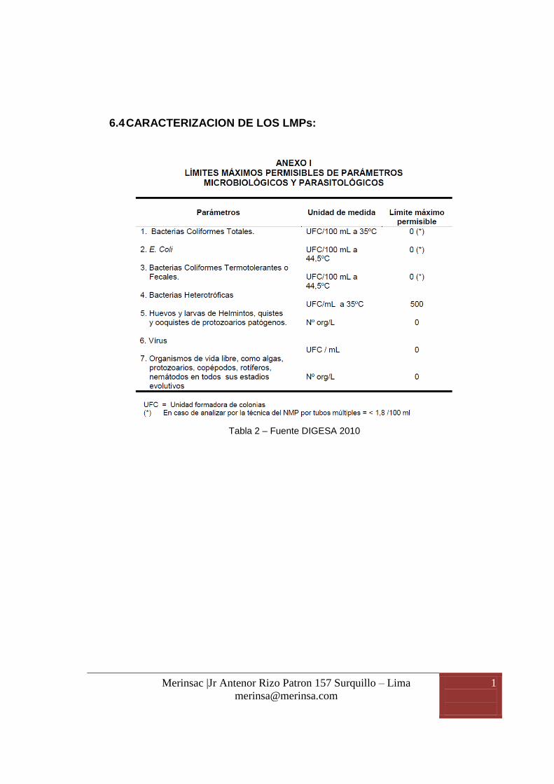
6.4 CARACTERIZACION DE LOS LMPs:
Tabla 2 – Fuente DIGESA 2010

Merinsac |Jr Antenor Rizo Patron 157 Surquillo – Lima
1
3
Tabla 3 – Fuente DIGESA 2010

Merinsac |Jr Antenor Rizo Patron 157 Surquillo – Lima
1
4
6.5 PROYECCIÓN DE LA CALIDAD DE AGUA FINAL:
Se ha empleado la simulación generada por el software del
proveedor del equipo, en este caso General Electric.
El software usado se llama Winflow, el reporte lo vemos a
continuación:

Winflows 3.0.0 Input Data Summary
Project Name SIMULACION GRAÑA - PROPUESTA1 - OSMOSIS GRANDEEngineer MIGUEL UBILLUS BORJALocation CARABAYLLOMail ID [email protected] No. 991145596Comments
Flowsheet Type Single Stage FlowsheetFeed Dosing YesAfterFeed Dosing NoProduct Dosing NoFeed Stripping NoProduct Stripping NoRaw Feed Bypass YesRO1 to RO1 Recycle Yes
Temperature, C 22.00Feed pH : 6.87Silt Density Index : 1.00
Feed Stream Composition(mg/l)Calcium (Ca) 233.25Magnesium (Mg) 16.39Sodium (Na) 45.11Potassium (K) 1.70Ammonia - N (NH4) 0.00Barium (Ba) 0.00Strontium (Sr) 0.00Iron (Fe) 0.00Manganese (Mn) 0.00Sulfate (SO4) 367.50Chloride (Cl) 117.46Fluoride (F) 0.00Nitrate (NO3) 101.21Bromide (Br) 0.00Phosphate (PO4) 0.00Boron (B) 0.00Silica (SiO2) 0.00Hydrogen Sulfide (H2S) 0.00Bicarbonate (HCO3) 146.17Carbon Dioxide (CO2) 27.66Carbonate (CO3) 0.07
Flow Rate Specifications
Product Flow: 158.00 gpmRO1 Recovery: 75.00 %Feed ByPass: 55.77 gpmRO1 to RO1 Recycle: 4.40 gpm
GE Water
Project Information
Flowsheet Configuration
Feed Information
Classification: GE Internal

First Pass Array Data
Stage Housing Elements Element TypeElement Age
(yr)Boost Drop Permeate A-Value B-Value
1 3 3 AG8040F400 3.00 0.00 0.00 0.00 7.00 5.002 2 3 AG8040F400 3.00 0.00 0.00 0.00 7.00 5.003 2 3 AG8040F400 3.00 0.00 0.00 0.00 7.00 5.00
Dosing Specification
Annual Change %Interstage Pressure, psi
Classification: GE Internal
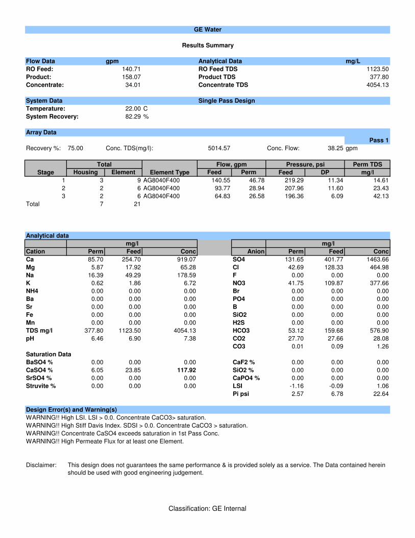
Flow Data gpm Analytical Data mg/L
RO Feed: 140.71 RO Feed TDS 1123.50
Product: 158.07 Product TDS 377.80
Concentrate: 34.01 Concentrate TDS 4054.13
System Data Single Pass Design
Temperature: 22.00 C
System Recovery: 82.29 %
Array Data
Pass 1
Recovery %: 75.00 Conc. TDS(mg/l): 5014.57 Conc. Flow: 38.25 gpm
Perm TDS
Housing Element Feed Perm Feed DP mg/l
1 3 9 AG8040F400 140.55 46.78 219.29 11.34 14.61
2 2 6 AG8040F400 93.77 28.94 207.96 11.60 23.43
3 2 6 AG8040F400 64.83 26.58 196.36 6.09 42.13
Total 7 21
Analytical data
Cation Perm Feed Conc Anion Perm Feed Conc
Ca 85.70 254.70 919.07 SO4 131.65 401.77 1463.66
Mg 5.87 17.92 65.28 Cl 42.69 128.33 464.98
Na 16.39 49.29 178.59 F 0.00 0.00 0.00
K 0.62 1.86 6.72 NO3 41.75 109.87 377.66
NH4 0.00 0.00 0.00 Br 0.00 0.00 0.00
Ba 0.00 0.00 0.00 PO4 0.00 0.00 0.00
Sr 0.00 0.00 0.00 B 0.00 0.00 0.00
Fe 0.00 0.00 0.00 SiO2 0.00 0.00 0.00
Mn 0.00 0.00 0.00 H2S 0.00 0.00 0.00
TDS mg/l 377.80 1123.50 4054.13 HCO3 53.12 159.68 576.90
pH 6.46 6.90 7.38 CO2 27.70 27.66 28.08
CO3 0.01 0.09 1.26
Saturation Data
BaSO4 % 0.00 0.00 0.00 CaF2 % 0.00 0.00 0.00
CaSO4 % 6.05 23.85 117.92 SiO2 % 0.00 0.00 0.00
SrSO4 % 0.00 0.00 0.00 CaPO4 % 0.00 0.00 0.00
Struvite % 0.00 0.00 0.00 LSI -1.16 -0.09 1.06
Pi psi 2.57 6.78 22.64
Design Error(s) and Warning(s)
WARNING!! High LSI. LSI > 0.0. Concentrate CaCO3> saturation.
WARNING!! High Stiff Davis Index. SDSI > 0.0. Concentrate CaCO3 > saturation.
WARNING!! Concentrate CaSO4 exceeds saturation in 1st Pass Conc.
WARNING!! High Permeate Flux for at least one Element.
Disclaimer: This design does not guarantees the same performance & is provided solely as a service. The Data contained herein
should be used with good engineering judgement.
Element Type
Total
Results Summary
GE Water
mg/l mg/l
Flow, gpm Pressure, psi
Stage
Classification: GE Internal

Classification: GE Internal

Flow Data gpm Analytical Data mg/L
RO Feed: 140.71 RO Feed TDS 1123.50
Product: 158.07 Product TDS 377.80
Concentrate: 34.01 Concentrate TDS 4054.13
System Data Single Pass Design
Temperature: 22.00 C
Pass 1
Feed Flow gpm 140.71
Feed Pressure psi 219.29
Recovery % 75.00
Permeate Flow gpm 105.50
Split Permeate Flow gpm 0.00
Pumping Summary
Pass 1
Feed Flow gpm 140.71
Discharge Pressure psi 219.29
Efficiency % 66.90
Power kW 21.55
Dosing
Chemical kg/day Dose To
Argo Analyser
Antiscalant Selected
Dose Rate in
Feed, kg/day
MDC700 83.84 15.00
GE Water
Process Data Sheet
Feed
Concentration in Brine,
ppm
Classification: GE Internal

Note: Dosed Antiscalant will flow to concentrate.
Cartridge Filter
26 RO.Zs 05-40 Filter Cartridges at 0.9084865 m3/hr Flow per TIE.
dP for new filters = 1.02 psi.
Classification: GE Internal

Classification: GE Internal

233.25 233.25 233.25 254.70 5.25
16.39 16.39 16.39 17.92 0.14
45.11 45.11 45.11 49.29 0.74
1.70 1.70 1.70 1.86 0.03
0.00 0.00 0.00 0.00 0.00
0.00 0.00 0.00 0.00 0.00
0.00 0.00 0.00 0.00 0.00
0.00 0.00 0.00 0.00 0.00
0.00 0.00 0.00 0.00 0.00
367.50 367.50 367.50 401.77 3.07
117.46 117.46 117.46 128.33 1.92
0.00 0.00 0.00 0.00 0.00
101.21 101.21 101.21 109.87 9.33
0.00 0.00 0.00 0.00 0.00
0.00 0.00 0.00 0.00 0.00
0.00 0.00 0.00 0.00 0.00
0.00 0.00 0.00 0.00 0.00
0.00 0.00 0.00 0.00 0.00
146.17 146.17 146.17 159.68 2.70
27.66 27.66 27.66 27.66 27.48
0.07 0.07 0.07 0.09 0.00
1028.87 1028.87 1028.87 1123.50 23.18
Flow gpm 192.08 55.77 136.31 140.71 102.30
Temperature C 22.00 22.00 22.00 22.00 22.00
Pressure psi 0.00 0.00 0.00 219.29 0.00
Osm. Pressure psi 6.25 6.25 6.25 6.78 0.38
pH 6.87 6.87 6.87 6.90 5.21
S&DI -0.47 -0.47 -0.47 -0.36 -5.47
Conductivity µS/cm 1445.00 1445.00 1445.00 1562.00 41.00
Saturation Data
BaSO4 % 0.00 0.00 0.00 0.00 0.00
CaF2 % 0.00 0.00 0.00 0.00 0.00
CaSO4 % 21.37 21.37 21.37 23.85 0.08
SiO2 % 0.00 0.00 0.00 0.00 0.00
SrSO4 % 0.00 0.00 0.00 0.00 0.00
CaPO4 % 0.00 0.00 0.00 0.00 0.00
Struvite % 0.00 0.00 0.00 0.00 0.00
LSI -0.18 -0.18 -0.18 -0.09 -3.82
Final Downstream
PermIons, mg/l
Streams Analytical Data
Manganese
Sulfate
Chloride
Fluoride
GE Water
Total Feed Feed Bypass Predosed Feed 1st Pass Feed
Calcium
Magnesium
Sodium
Potassium
Nitrate
Bromide
Ammonia - N
Barium
Strontium
Iron
Carbonate
TDS, mg/l
Phosphate
Boron
Silica
Hydrogen Sulfide
Carbon Dioxide
Bicarbonate
Classification: GE Internal

85.70 919.07
5.87 65.28
16.39 178.59
0.62 6.72
0.00 0.00
0.00 0.00
0.00 0.00
0.00 0.00
0.00 0.00
131.65 1463.66
42.69 464.98
0.00 0.00
41.75 377.66
0.00 0.00
0.00 0.00
0.00 0.00
0.00 0.00
0.00 0.00
53.12 576.90
27.70 28.08
0.01 1.26
377.80 4054.13
Flow gpm 158.07 34.01
Temperature C 22.00 22.00
Pressure psi 0.00 190.26
Osm. Pressure psi 2.57 22.64
pH 6.46 7.38
S&DI -1.73 1.11
Conductivity µS/cm 590.00 4805.00
Saturation Data
BaSO4 % 0.00 0.00
CaF2 % 0.00 0.00
CaSO4 % 6.05 117.92
SiO2 % 0.00 0.00
SrSO4 % 0.00 0.00
CaPO4 % 0.00 0.00
Struvite % 0.00 0.00
LSI -1.16 1.06
Carbon Dioxide
Carbonate
TDS, mg/l
Boron
Silica
Hydrogen Sulfide
Bicarbonate
Fluoride
Nitrate
Bromide
Phosphate
Manganese
Sulfate
Chloride
Streams Analytical Data
Ammonia - N
Barium
Strontium
Iron
Calcium
Magnesium
Sodium
Potassium
GE Water
Ions, mg/l Product Concentrate
Classification: GE Internal

Element By Element Data
Pass 1
Stage 1
Elem 1 Elem 2 Elem 3
Flow, gpm
Feed 46.90 41.58 36.39
Perm 5.32 5.19 5.08
Pressure, psi
Feed 219.29 214.75 210.99
Net Driving 209.22 204.02 199.27
Delta P 4.54 3.76 3.04
Feed Osm. Press 6.78 7.57 8.56
Other
Recovery, % 11.35 12.49 13.96
Beta (Conc. Pol.) 1.10 1.10 1.11
Flux, gfd 19.2 18.7 18.3
A-Value, µm/(s-MPa) 7.04 7.04 7.05
Permeate Ions, mg/l
Calcium 2.56 3.05 3.68
Magnesium 0.07 0.09 0.10
Sodium 0.37 0.44 0.53
Potassium 0.01 0.02 0.02
Ammonia - N 0.00 0.00 0.00
Barium 0.00 0.00 0.00
Strontium 0.00 0.00 0.00
Iron 0.00 0.00 0.00
Manganese 0.00 0.00 0.00
Sulfate 1.61 1.89 2.25
Chloride 0.90 1.07 1.31
Fluoride 0.00 0.00 0.00
Nitrate 4.50 5.37 6.50
Bromide 0.00 0.00 0.00
Phosphate 0.00 0.00 0.00
Boron 0.00 0.00 0.00
Silica 0.00 0.00 0.00
Hydrogen Sulfide 0.00 0.00 0.00
Bicarbonate 1.75 1.91 2.13
Carbon Dioxide 27.25 27.30 27.35
Carbonate 0.00 0.00 0.00
TDS, mg/l 12.27 14.43 17.26
pH 5.03 5.06 5.11
S&DI -6.15 -6.00 -5.83
Conductivity, µS/cm 23.00 26.00 30.00
Saturation Data
BaSO4, % 0.00 0.00 0.00
CaF2, % 0.00 0.00 0.00
CaSO4, % 0.04 0.04 0.05
SiO2 , % 0.00 0.00 0.00
SrSO4, % 0.00 0.00 0.00
CaPO4, % 0.00 0.00 0.00
Struvite, % 0.00 0.00 0.00
LSI -4.33 -4.21 -4.08
GE Water
Element detail Data
GE Water
Classification: GE Internal

Element By Element Data
Pass 1
Stage 2
Elem 1 Elem 2 Elem 3 Elem 4 Elem 5 Elem 6
Flow, gpm
Feed 46.96 42.01 37.19 32.49 27.93 23.49
Perm 4.96 4.82 4.69 4.57 4.44 4.29
Pressure, psi
Feed 207.96 203.38 199.53 196.36 193.80 191.78
Net Driving 194.38 188.80 183.58 178.52 173.34 167.60
Delta P 4.58 3.85 3.17 2.56 2.01 1.52
Feed Osm. Press 9.83 10.91 12.22 13.86 15.96 18.76
Other
Recovery, % 10.56 11.48 12.63 14.06 15.89 18.27
Beta (Conc. Pol.) 1.09 1.09 1.10 1.10 1.11 1.12
Flux, gfd 17.9 17.4 16.9 16.5 16.0 15.5
A-Value, µm/(s-MPa) 7.06 7.07 7.08 7.08 7.09 7.09
Permeate Ions, mg/l
Calcium 4.26 5.02 5.98 7.26 9.03 11.63
Magnesium 0.12 0.13 0.16 0.19 0.23 0.29
Sodium 0.61 0.71 0.84 1.01 1.24 1.58
Potassium 0.02 0.03 0.03 0.04 0.05 0.07
Ammonia - N 0.00 0.00 0.00 0.00 0.00 0.00
Barium 0.00 0.00 0.00 0.00 0.00 0.00
Strontium 0.00 0.00 0.00 0.00 0.00 0.00
Iron 0.00 0.00 0.00 0.00 0.00 0.00
Manganese 0.00 0.00 0.00 0.00 0.00 0.00
Sulfate 2.54 2.95 3.48 4.16 5.09 6.44
Chloride 1.54 1.82 2.19 2.69 3.38 4.41
Fluoride 0.00 0.00 0.00 0.00 0.00 0.00
Nitrate 7.56 8.91 10.64 12.94 16.12 20.77
Bromide 0.00 0.00 0.00 0.00 0.00 0.00
Phosphate 0.00 0.00 0.00 0.00 0.00 0.00
Boron 0.00 0.00 0.00 0.00 0.00 0.00
Silica 0.00 0.00 0.00 0.00 0.00 0.00
Hydrogen Sulfide 0.00 0.00 0.00 0.00 0.00 0.00
Bicarbonate 2.34 2.62 2.98 3.47 4.16 5.18
Carbon Dioxide 27.40 27.46 27.52 27.60 27.71 27.87
Carbonate 0.00 0.00 0.00 0.00 0.00 0.00
TDS, mg/l 19.83 23.19 27.50 33.21 41.12 52.70
pH 5.15 5.19 5.25 5.31 5.39 5.48
S&DI -5.68 -5.52 -5.33 -5.12 -4.87 -4.57
Conductivity, µS/cm 34.00 39.00 46.00 55.00 67.00 85.00
Saturation Data
BaSO4, % 0.00 0.00 0.00 0.00 0.00 0.00
CaF2, % 0.00 0.00 0.00 0.00 0.00 0.00
CaSO4, % 0.06 0.08 0.10 0.12 0.16 0.21
SiO2 , % 0.00 0.00 0.00 0.00 0.00 0.00
SrSO4, % 0.00 0.00 0.00 0.00 0.00 0.00
CaPO4, % 0.00 0.00 0.00 0.00 0.00 0.00
Struvite, % 0.00 0.00 0.00 0.00 0.00 0.00
LSI -3.97 -3.85 -3.72 -3.57 -3.39 -3.18
Element detail Data
Classification: GE Internal

Merinsac |Jr Antenor Rizo Patron 157 Surquillo – Lima
1
5
Tabla 4 – Resumen de resultados

Merinsac |Jr Antenor Rizo Patron 157 Surquillo – Lima
1
6
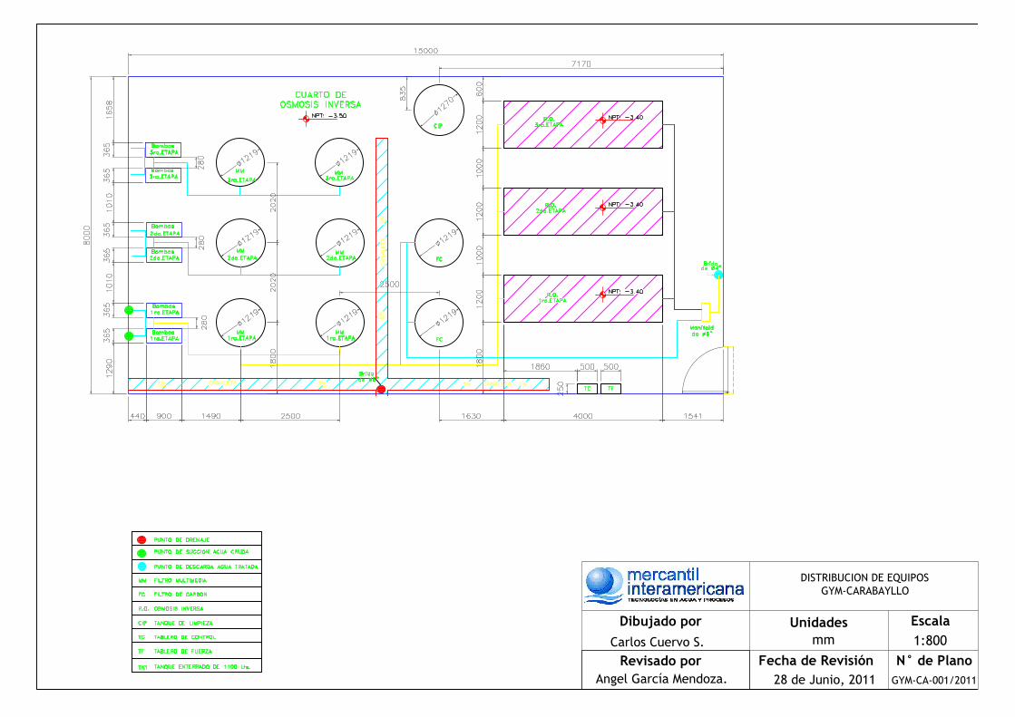
7. DESCRIPCION DEL SISTEMA
A continuación se presenta la lista de equipos principales de la planta
considerando todas las etapas del proyecto.
ETAPA 1 ETAPA 2 ETAPA 3
Dosificador de cloro gas 01 UND -----------
-----------
Bombas de alimentación + tablero variador 02 UND. 02 UND (adicionales)
02 UND (adicionales)
Filtros multimedia 02 UND. 02 UND (adicionales)
02 UND (adicionales)
Filtros de carbón activado 02 UND. -----------
-----------
Dosificador de antiescalante 01 UND 01 UND (adicionales)
01 UND (adicionales)
Dosificador de MBS 01 UND 01 UND (adicionales)
01 UND (adicionales)
Equipo de osmosis inversa 01 UND 01 UND (adicional)
01 UND (adicional)
Medidor de flujo 01 UND -----------
-----------
Medidor de ORP 01 UND 01 UND (adicional)
01 UND (adicional)
Dosificador de cloro final 01 UND -----------
-----------
Producción de agua 10l/s 10l/s 10l/s
----------- No se adiciona otro equipo.
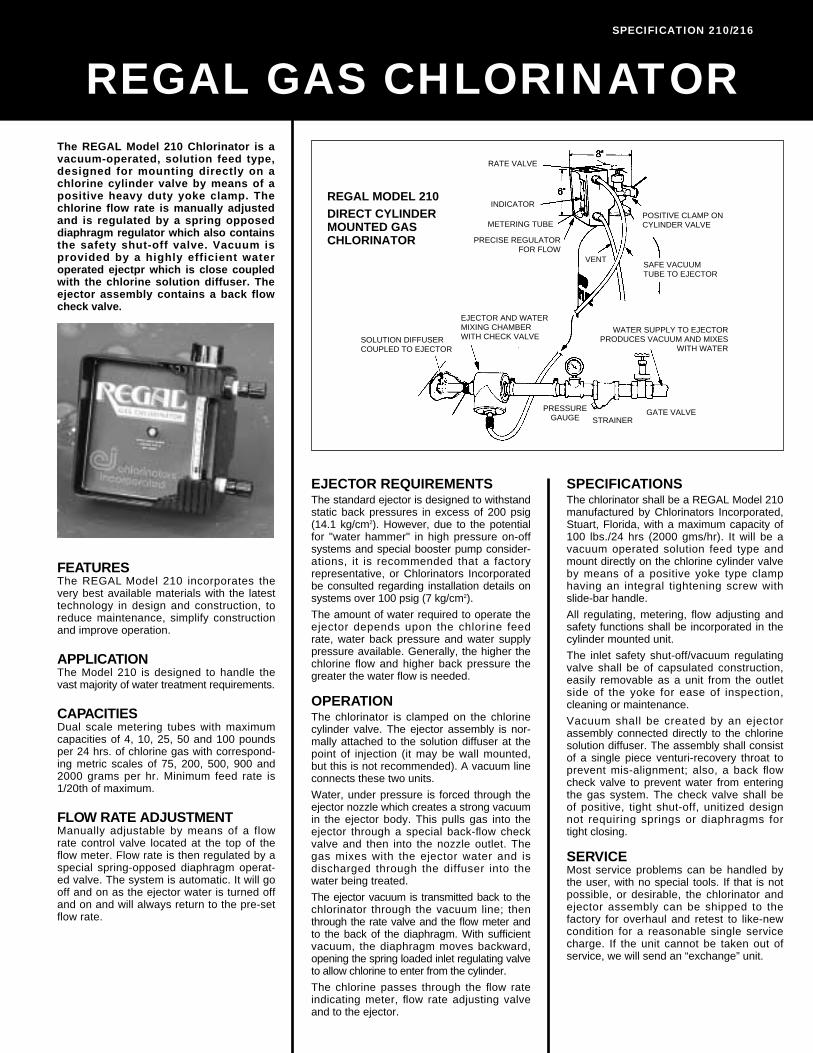
7.1 Dosificación de cloro gas
El equipo es de la marca Regal y está diseñado para que 02 Cloradores
sean montados directamente sobre la válvula del cilindro de cloro por
medio de una abrazadera resistente tipo yugo. El flujo de cloro es ajustado
y regulado manualmente por una perilla reguladora que va en la parte
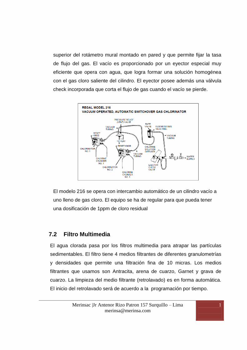
Merinsac |Jr Antenor Rizo Patron 157 Surquillo – Lima
1
7
superior del rotámetro mural montado en pared y que permite fijar la tasa
de flujo del gas. El vacío es proporcionado por un eyector especial muy
eficiente que opera con agua, que logra formar una solución homogénea
con el gas cloro saliente del cilindro. El eyector posee además una válvula
check incorporada que corta el flujo de gas cuando el vacío se pierde.
El modelo 216 se opera con intercambio automático de un cilindro vacío a
uno lleno de gas cloro. El equipo se ha de regular para que pueda tener
una dosificación de 1ppm de cloro residual
7.2 Filtro Multimedia
El agua clorada pasa por los filtros multimedia para atrapar las partículas
sedimentables. El filtro tiene 4 medios filtrantes de diferentes granulometrías
y densidades que permite una filtración fina de 10 micras. Los medios
filtrantes que usamos son Antracita, arena de cuarzo, Garnet y grava de
cuarzo. La limpieza del medio filtrante (retrolavado) es en forma automática.
El inicio del retrolavado será de acuerdo a la programación por tiempo.

Merinsac |Jr Antenor Rizo Patron 157 Surquillo – Lima
1
8
Las diferentes densidades de los medios filtrantes permiten que cuando se
realice el retrolavado y los medios estén flotando puedan recomponerse a su
estado inicial. Si los medios solo varían en su granulometría y son de la
misma densidad estos después del primer retrolavado se mezclan obviando
el efecto multimedia.
Modelo MM – 48
Velocidad de flujo de servicio 8 gpm/ft2
Marca del Tanque de FRP Wave Cyber
Medidas de tanque de FRP 48”x72”
Cantidad de tanques de FRP 02 unds.
Apertura superior e inferior 6” Brida
Válvulas de control x tanque 5 unidades
Modo de operación Hidráulica o neumática
Tipo de Controlador STAGER
Procedencia USA
Máxima presión de operación 100 PSI
Cantidad de Medio Filtrante 80 ft3 Total.
40 t3 por cada tanque
La operación de limpieza o retrolavado es automática en el equipo, esta es
operada por tiempo y comandada por un stager o controlador previamente
programado.
7.3 FILTRO DE CARBÓN ACTIVADO:
El agua filtrada pasa por este filtro de carbón activado donde se

Merinsac |Jr Antenor Rizo Patron 157 Surquillo – Lima
1
9
retiene los malos olores, sabores indeseables, compuestos
Halógenos, metales pesados. El inicio del retrolavado será de acuerdo
a la programación por tiempo.
Modelo GAC – 48
Velocidad de flujo de servicio 2.5 gpm/ft2
Marca del Tanque de FRP Wave Cyber
Medidas de tanque de FRP 48”x72”
Cantidad de tanques de FRP 02 unds.
Apertura superior e inferior 6” Brida
Válvulas de control x tanque 5 unidades
Modo de operación Hidráulica o neumática
Tipo de Controlador STAGER
Procedencia USA
Máxima presión de operación 100 PSI
Cantidad de Medio Filtrante 80 ft3 Total.
40 ft3 por cada tanque
Marca del Carbón Activado Hydraffin 40N, DONAU
CARBON GmbH & Co
Soporte de Grava de cuarzo 320 kilogramos, 160 Kg por
tanque
La operación de limpieza o retrolavado es automática en el equipo, esta es
operada por tiempo y comandada por un stager o controlador previamente
programado.
Merinsac |Jr Antenor Rizo Patron 157 Surquillo – Lima
2
0
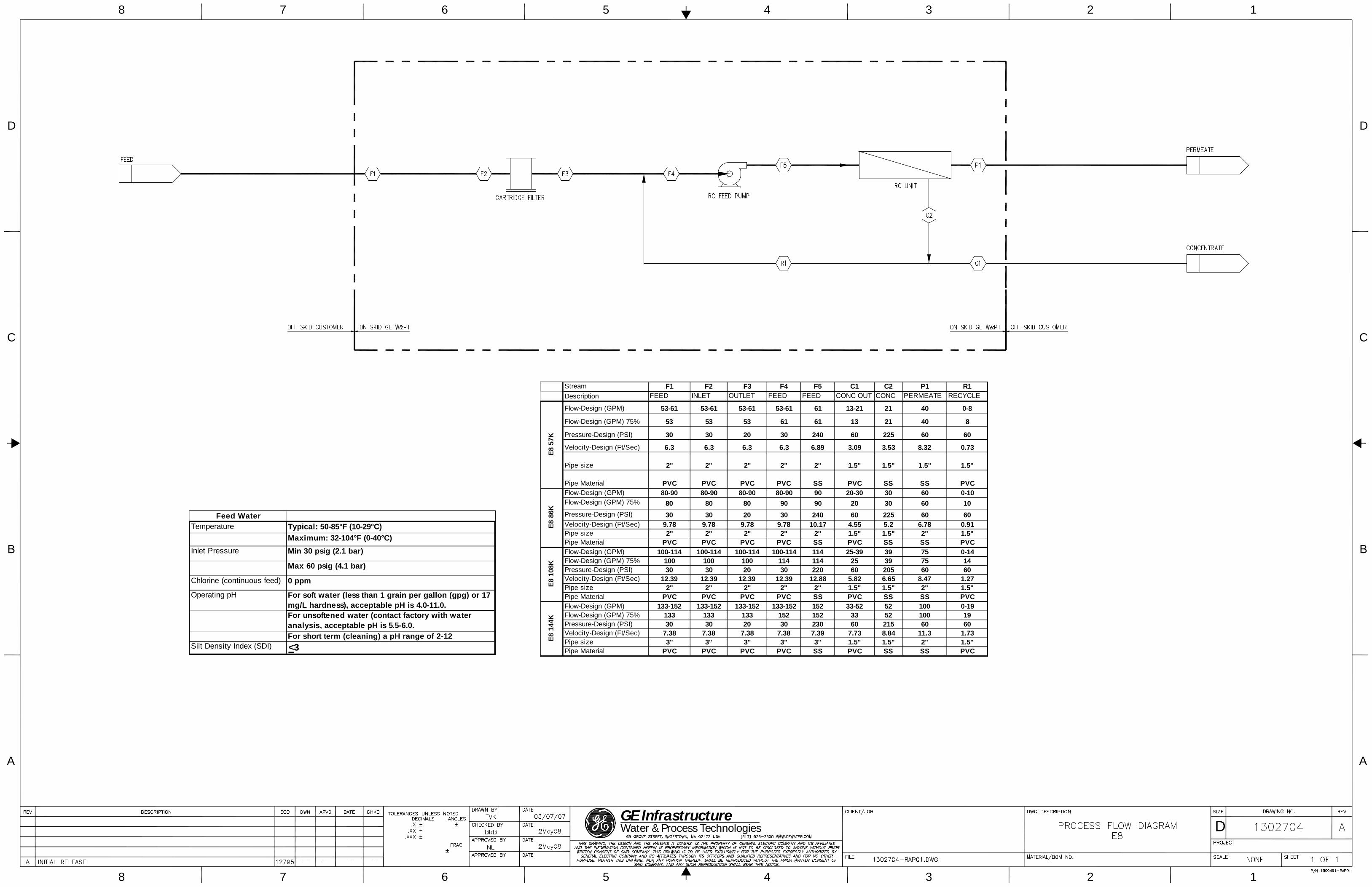
7.4 Osmosis inversa primera etapa:
El equipo de osmosis inversa de la primera etapa está compuesto por 21
membranas de alta presión de medidas 8” x 40” distribuidas en un arreglo
3-2-2, su conexión de entrada es de 3”, su descarga de permeado es de
2” y su concentrado es de 1.5”.
Posee un medidor de conductividad para poder determinar la cantidad de
sales (us/cm) a la descarga del equipo.
El equipo de osmosis posee las siguientes características:
Autoflush
Apagado por baja presión
Apagado por alta presión en el permeado
Medición del ph de permeado
Apagado del equipo por nivel alto del tanque de agua permeada
Estación de limpieza (CIP)
Registro de datos en un memoria SD-card
Es importante mencionar que las membranas de osmosis inversa no
soportan los oxidantes debido a su material (poliamida) por lo que el nivel
de cloro se debe mantener siempre igual a 0 ppm, esto se consigue con la
bomba de metabilsulto de sodio.

Merinsac |Jr Antenor Rizo Patron 157 Surquillo – Lima
2
1
Se debe evitar la precipitación de sales en la membrana y para esto
empleamos el químico antiescalante MSI310, especialmente indicado por
GE para este proceso.
El agua proveniente del filtro multimedia es nuevamente filtrado pero hasta
5 micras para luego elevar la presión a 200 psi y poder vencer la presión
osmótica del agua y generar tanto la línea de permeado como la de
concentrado.
Normalmente el concentrado va a poseer 3 a 4 veces más la salinidad del
agua de ingreso por lo que podemos estimar que estará en 3000 a 4000
us/cm (ver simulación)
Las características del OSMOSIS INVERSA son:
Osmosis Inversa
Fabricante General Electric
Marca de la membrana General Electric
Modelo del equipo Etapa 1 E8-144K-DLX
Produccion Estimada x equipo 100 gpm
Marca de la Bomba de altapresion Tonkaflow
Potencia del motor 40 Hp
Modelo de membrana AG-8040
Numero de Membranas 21.
Arreglo 3-2-2

Merinsac |Jr Antenor Rizo Patron 157 Surquillo – Lima
2
2
Voltaje 220V - Trifásico
Prefiltro 1 micras
Presión de Operación (psi) 180-220
Rango de Recobro % 75%
Retención de sales % 98 – 99.5
Temperatura de Operación (ºC) 13- 30
Manómetros 04 und
Medidor de conductividad Incluido
Sensor de baja presión Incluido
Autoflush incluido
Sensor de Alta presión en la línea
de permeado incluido

28
A
8
B
D
7 6 5 4 3 1
7 6 5 4 3 2 1
D
B
C
A
GE Water & Process Technologies D
C
28
A
8
B
D
7 6 5 4 3 1
7 6 5 4 3 2 1
D
B
C
A
GE Water & Process Technologies D
C

BWater & Process TechnologiesGE
BWater & Process TechnologiesGE

BWater & Process TechnologiesGE

BWater & Process TechnologiesGE

BWater & Process TechnologiesGE

BWater & Process TechnologiesGE
Merinsac |Jr Antenor Rizo Patron 157 Surquillo – Lima
2
3
7.5 Dosificación de cloro final:
Como hemos mencionado líneas arriba la dosificación de hipoclorito de sodio es
necesario para evitar un crecimiento bacteriológico al agua ya tratada, el valor a
considerar debe estar entre 0.5 – 1 ppm de cloro residual.
SISTEMA DE DOSIFICACION DE CLORO
Marca de la Bomba Dosificadora SEKO
Modelo AKL600NHH1000
Capacidad 2.5 LPH @ 20 Bar
Procedencia Italia
Consumo de energía 12.2 Watts
Tanque de almacenamiento de productos
químicos 1 unid.
Capacidad del tanque de químicos 50 Lt.
Sensor de nivel 1 unid.
Merinsac |Jr Antenor Rizo Patron 157 Surquillo – Lima
2
4
8. ANEXOS:
8.1 DIAGRAMA PID DE LA PLANTA DE TRATAMIENTO
8.2 FICHA TÉCNICA DE LOS EQUIPOS
8.3 LAYOUT
8.4 VISTA DE CORTE

N° de PlanoFecha de Revisión
Escala---
Revisado por
P&D GYMV
Dibujado por UnidadesmmCarlos Cuervo S.
Miguel Ubillus GYM-CA-005/201104 de Julio, 2011

N° de PlanoFecha de Revisión
Escala1:800
Revisado por
DISTRIBUCION DE EQUIPOSGYM-CARABAYLLO
Dibujado por UnidadesmmCarlos Cuervo S.
Angel García Mendoza. GYM-CA-001/201128 de Junio, 2011
1% 1%
1% 1%
1%
1%
CANALETA
CANALETA
CA
NA
LE
TA

N° de PlanoFecha de Revisión
Escala1:800
Revisado por
Dibujado por UnidadesmmCarlos Cuervo S.
Angel García Mendoza. GYM-CA-004/201128 de Junio, 2011
PLANO DE ELEVACIONCUARTO DE OSMOSIS INVERSA
GYM-CARABAYLLO

1%
1%
1% 1%
1%
1%
CANALETA
CANALETA
CA
NA
LE
TA
N° de PlanoFecha de Revisión
Escala1:800
Revisado por
VISTA DE PLANTA 1ra ETAPAGYM-CARABAYLLO
Dibujado por UnidadesmmCarlos Cuervo S.
Angel García Mendoza. GYM-CA-003/201128 de Junio, 2011
DETALLE REJILLA
CANALETA
SECCION B-B
B B
REJILLA
ESCALA 1:500
EJECTOR REQUIREMENTSThe standard ejector is designed to withstandstatic back pressures in excess of 200 psig(14.1 kg/cm2). However, due to the potentialfor "water hammer" in high pressure on-offsystems and special booster pump consider-ations, it is recommended that a factoryrepresentative, or Chlorinators Incorporatedbe consulted regarding installation details onsystems over 100 psig (7 kg/cm2).
The amount of water required to operate theejector depends upon the chlorine feedrate, water back pressure and water supplypressure available. Generally, the higher thechlorine flow and higher back pressure thegreater the water flow is needed.
OPERATIONThe chlorinator is clamped on the chlorinecylinder valve. The ejector assembly is nor-mally attached to the solution diffuser at thepoint of injection (it may be wall mounted,but this is not recommended). A vacuum lineconnects these two units.
Water, under pressure is forced through theejector nozzle which creates a strong vacuumin the ejector body. This pulls gas into theejector through a special back-flow checkvalve and then into the nozzle outlet. Thegas mixes with the ejector water and isdischarged through the diffuser into thewater being treated.
The ejector vacuum is transmitted back to thechlorinator through the vacuum line; thenthrough the rate valve and the flow meter andto the back of the diaphragm. With sufficientvacuum, the diaphragm moves backward,opening the spring loaded inlet regulating valveto allow chlorine to enter from the cylinder.
The chlorine passes through the flow rateindicating meter, flow rate adjusting valveand to the ejector.
The REGAL Model 210 Chlorinator is avacuum-operated, solution feed type,designed for mounting directly on achlorine cylinder valve by means of apositive heavy duty yoke clamp. Thechlorine flow rate is manually adjustedand is regulated by a spring opposeddiaphragm regulator which also containsthe safety shut-off valve. Vacuum isprovided by a highly efficient wateroperated ejectpr which is close coupledwith the chlorine solution diffuser. Theejector assembly contains a back flowcheck valve.
SPECIFICATIONSThe chlorinator shall be a REGAL Model 210manufactured by Chlorinators Incorporated,Stuart, Florida, with a maximum capacity of100 lbs./24 hrs (2000 gms/hr). It will be avacuum operated solution feed type andmount directly on the chlorine cylinder valveby means of a positive yoke type clamphaving an integral tightening screw withslide-bar handle.
All regulating, metering, flow adjusting andsafety functions shall be incorporated in thecylinder mounted unit.
The inlet safety shut-off/vacuum regulatingvalve shall be of capsulated construction,easily removable as a unit from the outletside of the yoke for ease of inspection,cleaning or maintenance.
Vacuum shall be created by an ejectorassembly connected directly to the chlorinesolution diffuser. The assembly shall consistof a single piece venturi-recovery throat toprevent mis-alignment; also, a back flowcheck valve to prevent water from enteringthe gas system. The check valve shall beof positive, tight shut-off, unitized designnot requiring springs or diaphragms fortight closing.
SERVICEMost service problems can be handled bythe user, with no special tools. If that is notpossible, or desirable, the chlorinator andejector assembly can be shipped to thefactory for overhaul and retest to like-newcondition for a reasonable single servicecharge. If the unit cannot be taken out ofservice, we will send an “exchange” unit.
REGAL GAS CHLORINATORSPECIFICATION 210/216
FEATURESThe REGAL Model 210 incorporates thevery best available materials with the latesttechnology in design and construction, toreduce maintenance, simplify constructionand improve operation.
APPLICATIONThe Model 210 is designed to handle thevast majority of water treatment requirements.
CAPACITIESDual scale metering tubes with maximumcapacities of 4, 10, 25, 50 and 100 poundsper 24 hrs. of chlorine gas with correspond-ing metric scales of 75, 200, 500, 900 and2000 grams per hr. Minimum feed rate is1/20th of maximum.
FLOW RATE ADJUSTMENTManually adjustable by means of a flowrate control valve located at the top of theflow meter. Flow rate is then regulated by aspecial spring-opposed diaphragm operat-ed valve. The system is automatic. It will gooff and on as the ejector water is turned offand on and will always return to the pre-setflow rate.
REGAL MODEL 210DIRECT CYLINDERMOUNTED GASCHLORINATOR
PRESSUREGAUGE
POSITIVE CLAMP ONCYLINDER VALVE
PRECISE REGULATOR FOR FLOW
WATER SUPPLY TO EJECTORPRODUCES VACUUM AND MIXES
WITH WATER
SAFE VACUUMTUBE TO EJECTOR
SOLUTION DIFFUSERCOUPLED TO EJECTOR
EJECTOR AND WATERMIXING CHAMBERWITH CHECK VALVE
INDICATOR
VENT
STRAINERGATE VALVE
RATE VALVE
METERING TUBE

The REGAL Model 216 AutomaticSwitchover Gas Chlorinator is a totallyvacuum-operated system which isdesigned to automatically switch thechlorine feed from an empty cylinder to afull cylinder. It is also designed to providesystem-backup. Should a problem developwith either vacuum regulator, chlorinationcan be continued. The chlorinators are ofthe vacuum-operated solution-feed type,designed for mounting directly on a chlorinecylinder valve. The switchovers are self-actuating, eliminating the need for a separateswitchover module. A separate gas flowmeter and rate control valve panel may belocated wherever it is most convenient forthe operator and connected between thevacuum regulator junction at the pressurerelief (vent) valve, and the ejector, by meansof safe vacuum tubing. The ejector assemblycontains a back flow check valve. Chlorinegas flow rate is regulated by a spring-opposed diaphragm regulator which is alsothe automatic safety shut-off valve. Shouldvacuum be interrupted for any reasonanywhere in the system the safety shut-off/inlet valve immediately closes, shuttingoff the chlorine supply from the cylinder. Apressure relief valve designed to “vent”the system also provides a centralinterconnection point for the vacuum tubing.
OTHER IMPORTANT FEATURES• System Back-up — Each cylinder’s chlorinator
has its own vacuum regulating diaphragm andsafety/inlet valve insuring that chlorination canbe continued if service should be required oneither chlorinator.
• Corrosion-resistant, Factory-adjusted DetentMechanism — Detent does not require anyfield adjustment assuring that cylinderswitchover will occur at the proper time, andthat all available gas in supply cylinder willbe used.
• In-Use/Stand-by Indication — Prominentindicator on face quickly tells which is thestand-by cylinder and which cylinder is inuse. Optional flowmeter panels are availablefor applications where the feed rate must beknown at the chlorinator and the flowmeter/rate valve panel cannot be seen.
CAPACITIESDual scale metering tubes with maximumcapacities of 4, 10, 25, 50 and 100 poundsper 24 hrs. of chlorine gas with correspondingmetric scales of 75, 200, 500, 900 and 2000grams per hr.
FLOW RATE ADJUSTMENTManually adjustable by means of a flow ratecontrol valve located at the top of the flowmeter. Flow rate is then regulated by a specialspring-opposed diaphragm operated valve.The system is automatic. It will go off and onas the ejector water is turned off and on andwill always return to the pre-set flow rate.
MATERIALS OF CONSTRUCTIONAll materials used in REGAL gas chlorinatorshave been carefully chosen for their excellentcorrosion-resistant, ultra-violet-resistant proper-
ties plus their ability to withstand stresses fargreater than will be encountered in actual use.
OPERATIONThe chlorinators are clamped onto the chlorinecylinder valves. The ejector assembly isnormally attached to the solution diffuser atthe point of injection. A vacuum line isconnected from each cylinder unit to the wall-mounted, pressure-relief (vent) valve, and asingle vacuum line connects the outlet of theconnector to a wall-mounted, flow-meter/ratevalve panel. The ejector is connected to therate valve panel with a single vacuum line.
Water, under pressure, is forced through theejector nozzle which creates a strong vacuumin the ejector body. This pulls gas into theejector through a special back-flow checkvalve and then into the nozzle outlet. The gasmixes with the ejector water and is dischargedthrough the diffuser into the water being treat-ed. The ejector vacuum is transmitted throughthe vacuum line to the rate valve and the flowmeter; then through the connector on thepressure-relief (vent) valve and on to the backof the operating chlorinator diaphragm. Withsufficient vacuum, the diaphragm movesbackward, opening the spring-loaded inlet reg-ulating valve to allow chlorine to enter from thecylinder. The chlorine passes through thechlorinator, the pressure-relief (vent) valveconnector and the flow rate indicatingmeter/flow rate adjusting valve to the ejector.
When the operating cylinder starts to run out,the vacuum starts to build up in the systemcausing the diaphragm of the chlorinator on“stand-by” to be drawn back, overcoming adetent mechanism and opening thesafety/inlet valve. This allows chlorine gas tobe withdrawn from the “stand-by” cylinder tosatisfy the increased system vacuum and thevacuum falls back to the operating level.
The original supply cylinder also continues tofeed until it is empty, virtually assuring thatthere will be no interruption of chlorination
and that full use will be made of all availablechlorine. This also reduces the possibility andrisk of returning cylinders with some remain-ing gas to the supplier.
SPECIFICATIONSThe chlorinator system shall be a vacuum-operated, solution-feed type and shall auto-matically switch the chlorine supply from anempty cylinder to a full cylinder. It shall beREGAL Model 216 manufactured byChlorinators Incorporated, Stuart, Florida, andshall have a maximum capacity of 100 lbs./24hrs (2000 gms/hr).
The Model 216 Vacuum-Operated AutomaticSwitchover Chlorinator shall consist of thefollowing components: Two (2) automaticswitchover vacuum regulators for mountingdirectly on chlorine gas cylinder valves, one(1) pressure-relief (vent) valve, one (1)chlorine gas flow meter panel with rate valve,& one (1) ejector/check valve assembly.
The vacuum regulators shall mount directlyonto the cylinder valve by means of a positiveyoke type clamp having an integral tighteningscrew with slide bar handle. The main vacuum-regulating diaphragm of each chlorinator shallhave a minimum operating area of 13 sq. inchesin order to achieve required accuracy andrepeatability of the set chlorine flow rate. Allmetallic bolts shall mate with metallic threadednuts or inserts. Plastic mating threads formetallic bolts shall not be acceptable.
Each chlorinator vacuum regulator shall haveits own diaphragm, safety-shutoff/inlet valveand switchover detent mechanism, thereby,allowing chlorination to continue should itbecome necessary to remove either vacuumregulator from service for cleaning or servicing.Switchover detent mechanism shall be madeof corrosion-resistant materials and shall notrequire any field adjustment.
SEE CONTENTS GUIDE 210 OR 216FOR STANDARD ACCESSORIES ANDSHIPPING WEIGHTS.
1044 SE Dixie Cutoff Road, Stuart, FL 34994 USA • Tel: 772-288-4854 • Fax: 772-287-3238 • www.regalchlorinators.com • E-mail: [email protected]
© 1998 Chlorinators Incorporated Printed in USA Pub. No. 598-3
REGAL MODEL 216VACUUM OPERATED, AUTOMATIC SWITCHOVER GAS CHLORINATOR
PRESSURE RELIEF(VENT) VALVE
CHLORINECYLINDER
NO. 1
CHLORINECYLINDER
NO. 1
FLOW METER RATEVALVE PANEL
EJECTORCHECKVALVE
CHLORINESOLUTIONDIFFUSER
WATERSUPPLY
RATEVALVEVACUUM
TUBING
VACUUMTUBING
RESETKNOB
RESET KNOB
VACUUMTUBING
TO VENT
CHLORINATORNO. 1
CHLORINATORNO. 2

Fact Sheet
Asia/Pacific Shanghai, China +86 (0) 411-8366-6489
©2006, General Electric Company. All rights reserved. *Trademark of General Electric Company; may be registered in one or more countries. FS1129EN 0606
Americas Watertown, MA +1-617-926-2500
Europe/Middle East/Africa Heverlee, Belgium +32-16-40-20-00
Find a contact near you by visiting gewater.com or e-mailing [email protected].
Global Headquarters Trevose, PA +1-215-355-3300
E8 Series 60 Hz Reverse Osmosis Machine 57,000 to 144,000 gallons per day
Figure 1: E8 Series 60 Hz
When you mention reverse osmosis (RO), GE Water & Process Technologies is the first name to come to mind. Our E-series RO machines (Figure 1) are de-signed for durable operation, high quality product water production, easy installation and straightforward control.
General Properties
Typical Applications • Process ingredient water • Safe drinking water • Boiler feed water • Ion exchange pre-treatment
Standard Economy Features • Energy saving 400 ft2 (37.2 m2) membrane
elements • SS high-pressure piping • 1-micron pre-filter and SS housing • Automatic inlet shut-off valve
• Accutrak RO microprocessor controller • Permeate and concentrate paddlewheel
flow sensors • Permeate conductivity sensor • Permeate tank level monitoring • SD card for collection of operating data • ALARMS: Low inlet pressure, high concen-
trate pressure, high temperature, high per-meate conductivity, motor fault, and fill-time exceeded
• Remote machine on/off capability • Feed water flush on shut down • Panel-mounted pre-filter, post-filter, primary,
and final pressure gauges
Deluxe (DLX) Features – in addition to ECN features • Inlet pH sensor • Chemical dosing pump for antiscalant dosing or
pH adjustment • Clean-In-Place pump plumbed, wired and
mounted; remote tank • ALARMS: Same as above plus high/
low inlet pH, high permeate pressure
Table 1: Operating Parameters
Operating Pressure 200-250 psig (13.8-17.2 bar)
Maximum Recovery 75% Nominal Rejection 95-98% Operating Temperature 55-85 °F (13-30 °C) Minimum Inlet Pressure 30 psig (2 bar) Design Temperature 77 °F (25 °C)

Page 2 FS1129EN 0606
Table 2: Materials of Construction
Frame Painted Carbon Steel Membrane Elements Desal AG8040F-400 Membrane Housing FRP Low Pressure Pipe Schedule 80 PVC High Pressure Pipe Stainless Steel Motor Starters NEMA 4
Table 3: Pump and Motor
Pump Manufacturer Tonkaflo Pump Type Multi-stage, centrifugal Materials SS shell/housing, Noryl* internals Castings SS inlet/discharge Motor 3-phase, TEFC, 460 VAC
Table 4: E8 Specifications - 60 Hz
Model E8-57K E8-86K E8-108K E8-144K
ECN DLX
1202846 1202284
1202850 1202286
1202833 1202287
1202835 1202288
Flow Specifications
Recovery Range: Permeate Rate: gpm (m3/h) Concentrate Rate: gpm (m3/h)
66-75% 40 (9)
21-13 (5-3)
66-75% 60 (14)
30-20 (7-5)
66-75% 75 (17)
39-25 (9-6)
66-75% 100 (23)
52-33 (12-8) Pump and Motor
RO Pump Model SS8510KA SS8512KB SS12508KC SS24006KE RO Motor: HP (KW) 15 (11.2) 20 (15) 25 (18.7) 40 (29.8) CIP Pump Model: (DLX only) SS5504G SS5504G SS8504G SS8504G CIP Motor: HP (KW) 5 (3.7) 5 (3.7) 7.5 (5.6) 7.5 (5.6)
Membrane Elements and Filters Membrane Quantity Array Pre-Filter Quantity
8 1-1-1
7, RO.Zs 01-40-XK
12 2-1-1
7, RO.Zs 01-40-XK
15 3-2
7, RO.Zs 01-40-XK
21 3-2-2
7, RO.Zs 01-40-XK Connections
Inlet: inch (cm) Permeate: inch (cm) Concentrate: inch (cm)
2.0 (5.1) 1.5 (3.8) 1.5 (3.8)
2.0 (5.1) 2.0 (5.1) 1.5 (3.8)
2.0 (5.1) 2.0 (5.1) 1.5 (3.8)
3.0 (7.6) 2.0 (5.1) 1.5 (3.8)
Dimensions & Weights
Height: inch (cm) Width: inch (cm) Depth: inch (cm) ECN Depth: inch (cm) DLX
76 (193) 153 (388) 42 (107) 91 (231)
76 (193) 153 (388) 42 (107) 91 (231)
76 (193) 153 (388) 42 (107) 91 (231)
76 (193) 153 (388) 42 (107)
103 (262)
Shipping Weight Estimate: lb (kg) ECN 2600 (1200) 3000 (1360) 3400 (1500) 3800 (1750)
Shipping Weight Estimate: lb (kg) DLX 2800 (1300) 3300 (1500) 3700 (1700) 4200 (1900)
Feed WaterTemperature Typical: 50-85°F (10-29°C)
Maximum: 32-104°F (0-40°C)
Inlet Pressure Min 30 psig (2.1 bar)
Max 60 psig (4.1 bar)
Chlorine (continuous feed) 0 ppm
Operating pH For soft water (less than 1 grain per gallon (gpg) or 17 mg/L hardness), acceptable pH is 4.0-11.0.For unsoftened water (contact factory with water analysis, acceptable pH is 5.5-6.0.For short term (cleaning) a pH range of 2-12
Silt Density Index (SDI) <3
Stream F1 F2 F3 F4 F5 C1 C2 P1 R1Description FEED INLET OUTLET FEED FEED CONC OUT CONC PERMEATE RECYCLE
Flow-Design (GPM) 53-61 53-61 53-61 53-61 61 13-21 21 40 0-8
Flow-Design (GPM) 75% 53 53 53 61 61 13 21 40 8
Pressure-Design (PSI) 30 30 20 30 240 60 225 60 60
Velocity-Design (Ft/Sec) 6.3 6.3 6.3 6.3 6.89 3.09 3.53 8.32 0.73
Pipe size 2" 2" 2" 2" 2" 1.5" 1.5" 1.5" 1.5"
Pipe Material PVC PVC PVC PVC SS PVC SS SS PVCFlow-Design (GPM) 80-90 80-90 80-90 80-90 90 20-30 30 60 0-10Flow-Design (GPM) 75% 80 80 80 90 90 20 30 60 10
Pressure-Design (PSI) 30 30 20 30 240 60 225 60 60Velocity-Design (Ft/Sec) 9.78 9.78 9.78 9.78 10.17 4.55 5.2 6.78 0.91Pipe size 2" 2" 2" 2" 2" 1.5" 1.5" 2" 1.5"Pipe Material PVC PVC PVC PVC SS PVC SS SS PVCFlow-Design (GPM) 100-114 100-114 100-114 100-114 114 25-39 39 75 0-14Flow-Design (GPM) 75% 100 100 100 114 114 25 39 75 14Pressure-Design (PSI) 30 30 20 30 220 60 205 60 60Velocity-Design (Ft/Sec) 12.39 12.39 12.39 12.39 12.88 5.82 6.65 8.47 1.27Pipe size 2" 2" 2" 2" 2" 1.5" 1.5" 2" 1.5"Pipe Material PVC PVC PVC PVC SS PVC SS SS PVCFlow-Design (GPM) 133-152 133-152 133-152 133-152 152 33-52 52 100 0-19Flow-Design (GPM) 75% 133 133 133 152 152 33 52 100 19Pressure-Design (PSI) 30 30 20 30 230 60 215 60 60Velocity-Design (Ft/Sec) 7.38 7.38 7.38 7.38 7.39 7.73 8.84 11.3 1.73Pipe size 3" 3" 3" 3" 3" 1.5" 1.5" 2" 1.5"Pipe Material PVC PVC PVC PVC SS PVC SS SS PVC
E8
86K
E8
108K
E8
144K
E8
57K
28
A
8
B
D
7 6 5 4 3 1
7 6 5 4 3 2 1
D
B
C
A
GE InfrastructureWater & Process Technologies D
C


teknaEVOsolenoid dosing pumps
innovation > technology > future

water & industry > solenoid dosing pumps tekna evo2
The evolution of solenoid dosing pumps
CompatiblePVDF pump head and ceramic ball valve asstandard
Full chemical compatibility
PVDF is suitable for almost all chemical usedin the Industrial, Waste Water Treatment andpotable Water applications
The use of Ceramic balls as standardimproves the pumping reliability and thechemical compatibility of the whole liquid end
evo
Inventory Reduction
Reduce spares stock holding
4 models that cover 1 to 60 lt/h with anoutput pressure up to 20 Bar
1 Casing allows skids to be pre-constructed,as the fixing points remain constant, and thepumps can be selected on confirmation of thedosing flow
flow rate from 1 to 20 lt/hflow rate from 20 to 60 lt/h
evo
CleverJust 4 Models, Just PVDF, All functions in one pump
Models
600
603
800
Models
803
water & industry > solenoid dosing pumps tekna evo4
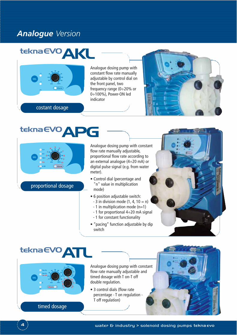
proportional dosage
SEL
Alarm
SEL
1:1
C
9
8
7
654
3
2
1 90
80
703040 50 60
20
10
min 100% 10
4:1
10:1
1:n
4-20
Analogue Version
teknaEVOAPGAnalogue dosing pump with constantflow rate manually adjustable,proportional flow rate according toan external analogue (4÷20 mA) ordigital pulse signal (e.g. from watermeter).
• Control dial (percentage and"n" value in multiplicationmode)
• 6 position adjustable switch:- 3 in division mode (1, 4, 10 = n)- 1 in multiplication mode (n=1)- 1 for proportional 4÷20 mA signal- 1 for constant functionality
• “pacing” function adjustable by dipswitch
timed dosage
Alarm
SELSEL
Time On
Time OnTime Off
C
90
80
703040
50 60
20
10
min 100%
0"
30"
60" 90"
120"
150"
180"
0"
30"
60" 90"
120"
150"
180"
teknaEVOATL
costant dosage
teknaEVOAKLAnalogue dosing pump withconstant flow rate manuallyadjustable by control dial onthe front panel, twofrequency range (0÷20% or0÷100%), Power-ON ledindicator
Analogue dosing pump with constantflow rate manually adjustable andtimed dosage with T on-T offdouble regulation.
• 3 control dials (flow ratepercentage - T on regulation -T off regulation)

innovation > technology > future 5
Digital Version
proportional dosage
ESCstartstop
PROGmodeenter
Alarm
teknaEVO TPGDigital dosing pump withconstant flow rate manuallyadjustable, proportional flow rateaccording to an external analog(4÷20 mA) or digital pulse signal(e.g. from water meter).
This digital version of the APG,includes additonal characteristics:Timer function, ppm dosing,statistics, password and On/Offinput (remote switch)
proportional dosage
CAL
ESCstartstop
PROGmodeenter
Alarm
teknaEVO TPRDigital dosing pump withpH/Redox control meter built in.
• Digital interface for constant orproportional dosing, dependingon the measured pH or Rx value
• PT100 probe input forthermal compensation
• Repetition alarm relay
• Input On-Off for remotecontrol
• 4÷20 mA output for measuretransmission
timed dosage
ESCstartstop
PROGmodeenter
Alarm
teknaEVO TCKDigital dosing pump withconstant flow rate manuallyadjustable, or timer control.
• Programmable timed relay

water & industry > solenoid dosing pumps tekna evo6
100 ÷ 240 Vac50-60 Hz
24 ÷ 48 Vac (just for AKL and APG version)
AKL 603 N H H 0 000
AKL
APG
ATL
TPG
TPRTCK
Analogue dosing pump with constant flow rate manually adjustableAnalogue dosing pump with constant flow rate manually adjustable, with proportional flow rate according toan external analog (4÷20 mA) or digital signal (water meter)Analogue dosing pump with constant flow rate manually adjustable and timed dosage with T on-T off doubleregolation
Digital dosing pump with constant flow rate manually adjustable, with proportional flow rate according to anexternal analog (4÷20 mA) or digital signal (water meter)Digital dosing pump with pH/Redox control meter on board
Digital dosing pump with constant flow rate or timed
Digital
Analogue
VersionInterfaceCode Description
ModelCode Pressure
[bar]Flow rate
[lt/h]Fequency max[stroke./min]
Stroke capacity[cc/stroke]
Ø ConnectionsIN / OUT [mm]
Consumption[W]
2018
2.53
1200,350,41
4 / 6 suc.4 / 7 dis.
12,0600121082
4568
160
0,420,520,630,83
4 / 6 12,2603
121051
7101518
320
0,360,520,780,94
4 / 6 23,9800
5421
20254054
300
1,111,392,22
3
8 / 12 22,2803
Power supplyCode
NO
Pump head materialCode Balls DiaphragmPump head Connections
H Ceramic PTFEPVDF
Installation KitCode
H PVDF
SealsCode Materials
0 FPM
1 EPDM
OptionsCode Description
000 Standard
Code
Materials

C
A
D
B
• Casing made of PP reinforced
with glass fibre
• IP 65 rated
• PTFE diaphragm
• Level control input
• Priming valve
• Complete standard installation
kit composed by: foot filter and
injection valve, PVC suction
tube, PE delivery tube and
fixing bracket
innovation > technology > future 7
Technical Features - Flow Rate and Dimensional Drawings
Model
600603800803
A(Height) [mm]
B(Width) [mm]
C(Depth) [mm]
D(Max Height) [mm]
231 119 145 257
149
600
603
800
803
Pressure[bar]
FlowRate[lt/h]

water & industry > solenoid dosing pumps tekna evo8
Typical Installation
40kontrol
MODEesc
CALente r
Backpressure valve
Pulse-emitter water meter
Flow Sensor
Multifuction ValveBleed valve
Mixer
Priming-aid
Tank
Suction Devices
On pulse-emitter water meter
On control instrument