megathrust motors - nsk ltd. 1 megathrust motors the megathrust motor is a linear motor system that...
TRANSCRIPT
Maximum speed 2 000 mm/s, 1 µm resolutionNSK Megathrust Motors greatly contribute to cutting-edge precision technology.
Megathrust MotorsPM Series/Y Series
1
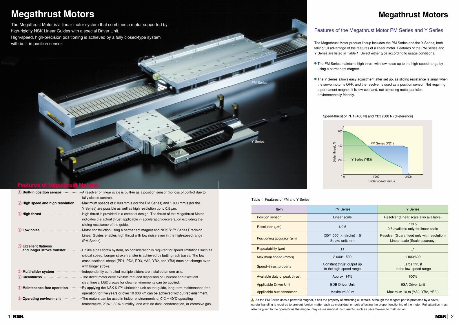
Megathrust MotorsThe Megathrust Motor is a linear motor system that combines a motor supported by
high-rigidity NSK Linear Guides with a special Driver Unit.
High-speed, high-precision positioning is achieved by a fully closed-type system
with built-in position sensor.
Megathrust Motors
Features of the Megathrust Motor PM Series and Y Series
The Megathrust Motor product lineup includes the PM Series and the Y Series, both
taking full advantage of the features of a linear motor. Features of the PM Series and
Y Series are listed in Table 1. Select either type according to usage conditions.
The PM Series maintains high thrust with low noise up to the high-speed range by
using a permanent magnet.
The Y Series allows easy adjustment after set up, as sliding resistance is small when
the servo motor is OFF, and the resolver is used as a position sensor. Not requiring
a permanent magnet, it is low-cost and, not attracting metal particles,
environmentally friendly.
Item PM Series Y Series
Position sensor Linear scale Resolver (Linear scale also available)
Resolution (µm) 1/0.51/0.5
0.5 available only for linear scale
Positioning accuracy (µm)(30/1 000) × (stroke) + 5 Resolver (Guaranteed only with resolution)
Stroke unit: mm Linear scale (Scale accuracy)
Repeatability (µm) ±1 ±1
Maximum speed (mm/s) 2 000/1 500 1 800/600
Speed–thrust propertyConstant thrust output up Large thrustto the high-speed range in the low-speed range
Available duty of peak thrust Approx. 14% 100%
Applicable Driver Unit EDB Driver Unit ESA Driver Unit
Applicable butt connection Maximum 30 m Maximum 10 m (YA2, YB2, YB3 )
2 0001 000
400
200
600
00
Slid
er th
rust
, N
Slider speed, mm/s
PM Series (PD1)
Y Series (YB3)
Table 1 Features of PM and Y Series
As the PM Series uses a powerful magnet, it has the property of attracting all metals. Although the magnet part is protected by a cover,
careful handling is required to prevent foreign matter such as metal dust or tools affecting the proper functioning of the motor. Full attention must
also be given to the operator as the magnet may cause medical instruments, such as pacemakers, to malfunction.
PM Series
Y Series
Speed-thrust of PD1 (400 N) and YB3 (588 N) (Reference)
Features of Megathrust Motors:➀ Built-in position sensor………………A resolver or linear scale is built-in as a position sensor (no loss of control due to
fully closed control).
➁ High speed and high resolution ……Maximum speeds of 2 000 mm/s (for the PM Series) and 1 800 mm/s (for the
Y Series) are possible as well as high resolution up to 0.5 µm.
➂ High thrust ……………………………High thrust is provided in a compact design. The thrust of the Megathrust Motor
indicates the actual thrust applicable in acceleration/deceleration excluding the
sliding resistance of the guide.
➃ Low noise ………………………………Motor construction using a permanent magnet and NSK S1™ Series Precision
Linear Guides enables high thrust with low noise even in the high-speed range
(PM Series).
➄ Excellent flatness and longer stroke transfer …………Unlike a ball screw system, no consideration is required for speed limitations such as
critical speed. Longer stroke transfer is achieved by butting rack bases. The low
cross-sectional shape (PD1, PD2, PD3, YA2, YB2, and YB3) does not change even
with longer stroke.
➅ Multi-slider system……………………Independently controlled multiple sliders are installed on one axis.
➆ Cleanliness ……………………………The direct motor drive exhibits reduced dispersion of lubricant and excellent
cleanliness. LG2 grease for clean environments can be applied.
➇ Maintenance-free operation…………By applying the NSK K1™ lubrication unit on the guide, long-term maintenance-free
operation for five years or over 10 000 km can be achieved without replenishment.
➈ Operating environment ………………The motors can be used in indoor environments of 0˚C ~ 40˚C operating
temperature, 20% ~ 80% humidity, and with no dust, condensation, or corrosive gas.
2
How to Select Megathrust Motors
In selecting Megathrust Motors, the important factors are maximum acceleration, maximum speed, load (mass and size), and duty. Calculation formulas➀ Find peak thrust F ……………F = maximum acceleration × (mass of load + mass of slider) × η (safety factor) (Reference 1)➁ Obtain average thrust…………Obtain the average thrust by the drive pattern of actual operation. (Reference 2) ➂ Select Series of motors ………Confirm that the peak thrust obtained in ➀ falls within the usable range through the speed and thrust
properties of the motor. Especially for the Y Series, pay attention to the peak thrust variationdepending on speed. For the PM Series, confirm that the average thrust falls within the rated thrust range.
➃ Confirm the mass of load ……Confirm that the load is within the permissible mass of load and transportable moment for theselected motor size.
➄ Calculate the travelling life……Calculate the travelling life using the maximum load applied to the linear guide according to the loadconditions. (Reference 3)
➅ Confirm necessity of external
regeneration resistance ………Confirm necessity of regeneration resistor through the operating conditions. (Reference 4)
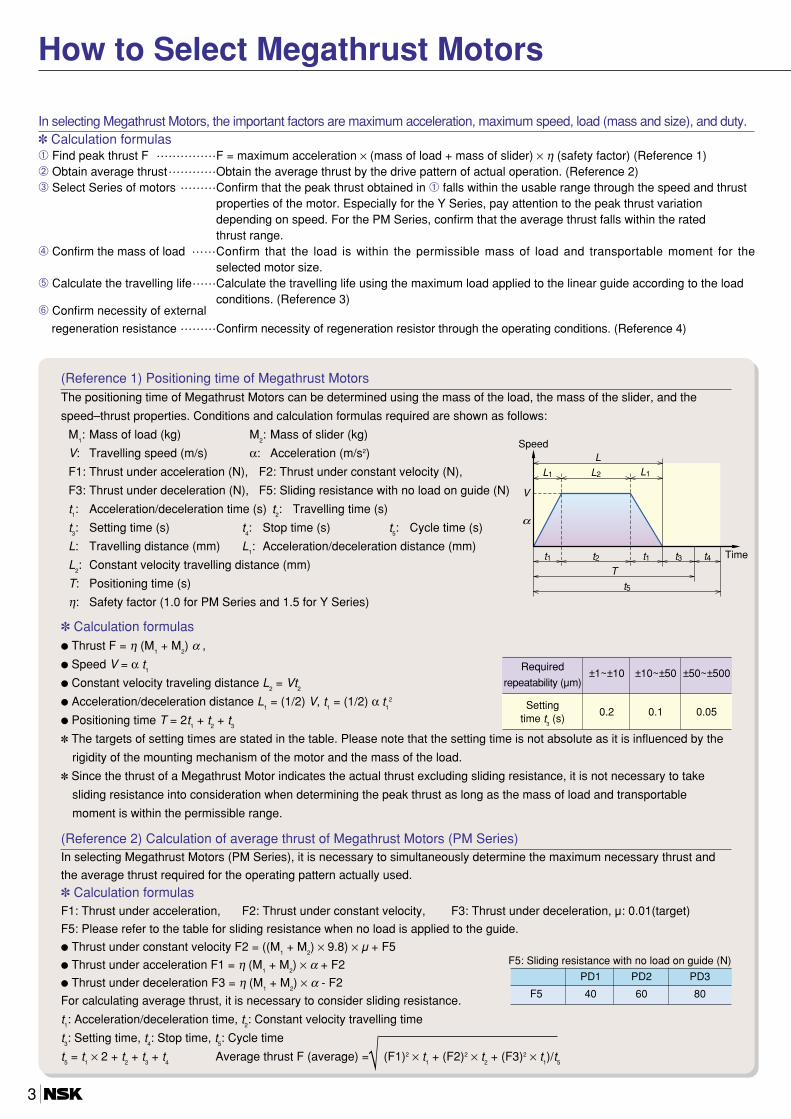
(Reference 1) Positioning time of Megathrust MotorsThe positioning time of Megathrust Motors can be determined using the mass of the load, the mass of the slider, and the
speed–thrust properties. Conditions and calculation formulas required are shown as follows:
M1: Mass of load (kg) M
2: Mass of slider (kg)
V: Travelling speed (m/s) α: Acceleration (m/s2)
F1: Thrust under acceleration (N), F2: Thrust under constant velocity (N),
F3: Thrust under deceleration (N), F5: Sliding resistance with no load on guide (N)
t1: Acceleration/deceleration time (s) t
2: Travelling time (s)
t3: Setting time (s) t
4: Stop time (s) t
5: Cycle time (s)
L: Travelling distance (mm) L1: Acceleration/deceleration distance (mm)
L2: Constant velocity travelling distance (mm)
T: Positioning time (s)
η: Safety factor (1.0 for PM Series and 1.5 for Y Series)
Calculation formulas Thrust F = η (M
1+ M
2) α ,
Speed V = α t1
Constant velocity traveling distance L2= Vt
2
Acceleration/deceleration distance L1= (1/2) V, t
1= (1/2) α t
12
Positioning time T = 2t1+ t
2+ t
3
The targets of setting times are stated in the table. Please note that the setting time is not absolute as it is influenced by the
rigidity of the mounting mechanism of the motor and the mass of the load.
Since the thrust of a Megathrust Motor indicates the actual thrust excluding sliding resistance, it is not necessary to take
sliding resistance into consideration when determining the peak thrust as long as the mass of load and transportable
moment is within the permissible range.
α
L1
t1 t2 t1
t5
t3 t4
L1
LL2
T
V
Speed
Time
Required±1~±10 ±10~±50 ±50~±500
repeatability (µm)
Setting0.2 0.1 0.05
time t3(s)
(Reference 2) Calculation of average thrust of Megathrust Motors (PM Series)In selecting Megathrust Motors (PM Series), it is necessary to simultaneously determine the maximum necessary thrust and
the average thrust required for the operating pattern actually used.
Calculation formulasF1: Thrust under acceleration, F2: Thrust under constant velocity, F3: Thrust under deceleration, µ: 0.01(target)
F5: Please refer to the table for sliding resistance when no load is applied to the guide.
Thrust under constant velocity F2 = ((M1+ M
2) × 9.8) × µ + F5
Thrust under acceleration F1 = η (M1+ M
2) × α + F2
Thrust under deceleration F3 = η (M1+ M
2) × α - F2
For calculating average thrust, it is necessary to consider sliding resistance.
t1: Acceleration/deceleration time, t
2: Constant velocity travelling time
t3: Setting time, t
4: Stop time, t
5: Cycle time
t5= t
1× 2 + t
2+ t
3+ t
4Average thrust F (average) =√ (F1)2 × t
1+ (F2)2 × t
2+ (F3)2 × t
1)/t
5
F5: Sliding resistance with no load on guide (N)
PD1 PD2 PD3
F5 40 60 80
3

(Reference 3) Calculation of travelling life of Megathrust MotorsThe approximate travelling life of a Megathrust Motor (PM Series) can be assumed by the following calculation formulas. If
lifetime falls short of the required travelling life, use a motor construction with an additional supplementary guide, or
separately design a table receiving a load mass to use the Megathrust Motor as a driving source.
Calculation formulasObtain the maximum load W applied on one ball slide (considered as a static load) under conditions of no external shock
or vibration.
For a simple load (where the center of the slider and the center of gravity of the load mass are matched on the plane
surface): W = (M1+ M
2)/(number of bearings)
In case of load acting as moment load: Moment load component W1 = (carrying load × eccentric value of gravity-center
position/guide space in the direction of moment)/2
W = (M1+ M
2)/(number of ball slides) + W1
Calculate the travelling life of a guide at maximum load W (N).
Travelling life L (km) = 50 × [C (basic dynamic load rating of the guide)/fw/(W + K) ]3
Please consult NSK if travelling life is smaller than the required design life.
Hardness coefficient is defined as 1.0. Load coefficient fw is 1.0 to 3, depending on usage conditions; this should usually
be set to 1.2.
C and K values are as shown in the following table.
(Reference 4) Selection of regeneration resistor (PM Series)➀ Find the energy possessed by a Megathrust Motor at deceleration.
Energy is obtained as the sum of kinetic energy and potential energy. h: height (m)Kinetic energy = 1
2 × (M1+ M
2) × V2 Potential energy = (M
1+ M
2) × 9.8 × h
For horizontal drive, it is not necessary to consider potential energy.
➁ Obtain deceleration time.a (maximum deceleration) = peak thrust/(M
1+ M
2)
t (deceleration time) = V/a or deceleration time for the operating pattern
➂ Regeneration damping capacity of internal regeneration resistor (in case of EDB Driver Unit)Regeneration damping capacity = 240 × t + 40
➃ When energy possessed at deceleration is smaller than regeneration damping capacity, an external regeneration resistor is
not required. However, when it is larger, an external regeneration resistor is required.
➄ In case of stopping in 0.5 s when moving a load mass of 200 kg at 2 m/s,
Energy possessed at deceleration: 400 (J) (the sum of kinetic energy and potential energy)
Regeneration energy consumed by the Driver Unit and motor body: 160 (J) 160 = 240 × 0.5 + 40
Regeneration energy consumed by the Driver Unit and motor body becomes less than the energy possessed at
deceleration, so that an external regeneration resistor is required.
➅ Damping capacity of an external regeneration resistor (Determined depending on Driver Unit specifications.) For an EDB Driver Unit,
External regeneration resistor: RH 220 B 100 (Ω)
Power consumption at regeneration ON: 1 400 (W)
Regeneration energy which has to be consumed with an external regeneration resistor: 240 (J) = 400 –160 Power consumption of an external regeneration resister: 480 (W) = 240 (J) ÷ 0.5 (s)
No problem occurs as long as power consumption is 1400 (W) or less.
Use with natural cooling: No problem occurs so long as average duty consumes 350 (W) or less (with other than
deceleration time taken as zero).
Limit of usage rate at forced cooling: When duty consumes power of more than 350 (W), usable consumed power can be
increased by applying forced cooling to regeneration resistance.
C and KPD1 PD2 PD3
C 8 500 8 500 8 500
K 450 450 540
4
Megathrust Motors
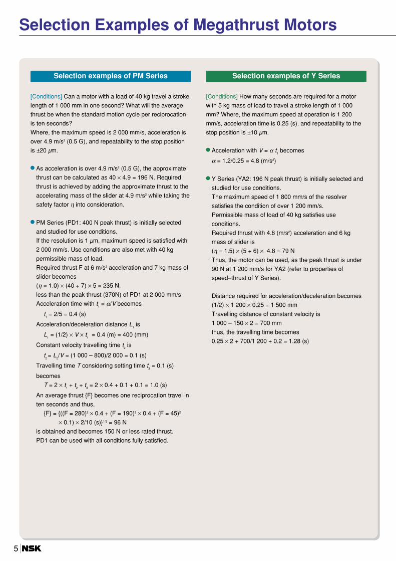
[Conditions] Can a motor with a load of 40 kg travel a stroke
length of 1 000 mm in one second? What will the average
thrust be when the standard motion cycle per reciprocation
is ten seconds?
Where, the maximum speed is 2 000 mm/s, acceleration is
over 4.9 m/s2 (0.5 G), and repeatability to the stop position
is ±20 µm.
As acceleration is over 4.9 m/s2 (0.5 G), the approximate
thrust can be calculated as 40 × 4.9 = 196 N. Required
thrust is achieved by adding the approximate thrust to the
accelerating mass of the slider at 4.9 m/s2 while taking the
safety factor η into consideration.
PM Series (PD1: 400 N peak thrust) is initially selected
and studied for use conditions.
If the resolution is 1 µm, maximum speed is satisfied with
2 000 mm/s. Use conditions are also met with 40 kg
permissible mass of load.
Required thrust F at 6 m/s2 acceleration and 7 kg mass of
slider becomes
(η = 1.0) × (40 + 7) × 5 = 235 N,
less than the peak thrust (370N) of PD1 at 2 000 mm/s
Acceleration time with t1= α/V becomes
t1= 2/5 = 0.4 (s)
Acceleration/deceleration distance L1is
L1= (1/2) × V × t
1= 0.4 (m) = 400 (mm)
Constant velocity travelling time t2is
t2 = L
2/V = (1 000 – 800)/2 000 = 0.1 (s)
Travelling time T considering setting time t3= 0.1 (s)
becomes
T = 2 × t1+ t
2+ t
3= 2 × 0.4 + 0.1 + 0.1 = 1.0 (s)
An average thrust F becomes one reciprocation travel in
ten seconds and thus,
F = ((F = 280)2 × 0.4 + (F = 190)2 × 0.4 + (F = 45)2
× 0.1) × 2/10 (s)1/2 = 96 N
is obtained and becomes 150 N or less rated thrust.
PD1 can be used with all conditions fully satisfied.
[Conditions] How many seconds are required for a motor
with 5 kg mass of load to travel a stroke length of 1 000
mm? Where, the maximum speed at operation is 1 200
mm/s, acceleration time is 0.25 (s), and repeatability to the
stop position is ±10 µm.
Acceleration with V = α t1becomes
α = 1.2/0.25 = 4.8 (m/s2)
Y Series (YA2: 196 N peak thrust) is initially selected and
studied for use conditions.
The maximum speed of 1 800 mm/s of the resolver
satisfies the condition of over 1 200 mm/s.
Permissible mass of load of 40 kg satisfies use
conditions.
Required thrust with 4.8 (m/s2) acceleration and 6 kg
mass of slider is
(η = 1.5) × (5 + 6) × 4.8 = 79 N
Thus, the motor can be used, as the peak thrust is under
90 N at 1 200 mm/s for YA2 (refer to properties of
speed–thrust of Y Series).
Distance required for acceleration/deceleration becomes
(1/2) × 1 200 × 0.25 = 1 500 mm
Travelling distance of constant velocity is
1 000 – 150 × 2 = 700 mm
thus, the travelling time becomes
0.25 × 2 + 700/1 200 + 0.2 = 1.28 (s)
Selection Examples of Megathrust Motors
5
Selection examples of PM Series Selection examples of Y Series
PM Series
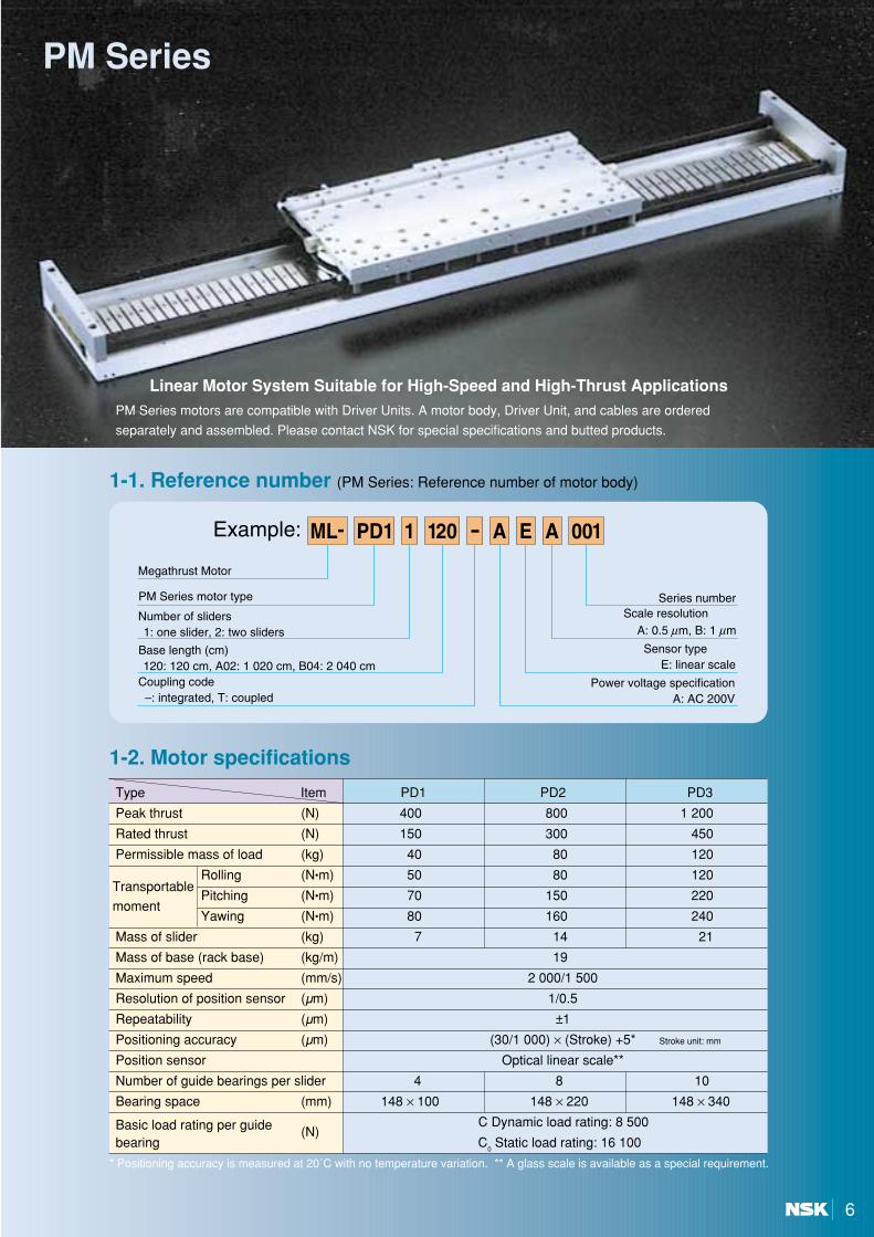
Linear Motor System Suitable for High-Speed and High-Thrust Applications
1-2. Motor specifications
* Positioning accuracy is measured at 20˚C with no temperature variation. ** A glass scale is available as a special requirement.
Type Item PD1 PD2 PD3
Peak thrust (N) 400 800 1 200
Rated thrust (N) 150 300 450
Permissible mass of load (kg) 40 80 120
TransportableRolling (N•m) 50 80 120
Pitching (N•m) 70 150 220moment
Yawing (N•m) 80 160 240
Mass of slider (kg) 7 14 21
Mass of base (rack base) (kg/m) 19
Maximum speed (mm/s) 2 000/1 500
Resolution of position sensor (µm) 1/0.5
Repeatability (µm) ±1
Positioning accuracy (µm) (30/1 000) × (Stroke) +5* Stroke unit: mm
Position sensor Optical linear scale**
Number of guide bearings per slider 4 8 10
Bearing space (mm) 148 × 100 148 × 220 148 × 340
Basic load rating per guide (N)C Dynamic load rating: 8 500
bearing C0Static load rating: 16 100
PM Series motors are compatible with Driver Units. A motor body, Driver Unit, and cables are ordered
separately and assembled. Please contact NSK for special specifications and butted products.
6
1-1. Reference number (PM Series: Reference number of motor body)

PM Series
1-4. System configuration (PM Series)
Fig. 2 System configuration
DC 24V
PM Series Megathrust Motor body
Sensor unit (optional)
Cable-guide device unit (optional)
To control powerTo main power
Handy Terminal(optional)
Master Controller
Cable set (flexible cable)
Driver Unit
Cables indicated with dotted lines or shown inside of are to be prepared by the customer.
1-3. Properties of speed and thrust
Fig. 1 Properties of speed and thrust
00
50
100
150
200
250
300
350
400
1.0 2.0 00
200
400
650
800
1 000
1 200
1.0 2.000
200
400
600
800
1.0 2.0
Thr
ust,
N
Thr
ust,
N
Thr
ust,
N
Peak thrust
Rated thrust
Peak thrust
Rated thrust
Peak thrust
Rated thrust
Slider speed, m/s Slider speed, m/s Slider speed, m/s
PD1 PD2 PD3
7
100
90
L (180×N)
90
40 40
104
72 20
40
110
330
15 220
20022
0
10
10 15
10
100
100
73
195
195
180
180
200
180
20
180P× (N–1)
10
4-M8 Depth 16
Stopper
Minus Plus 2N- 9 thru ~ 14 Depth 3.5φ φ
Stroke
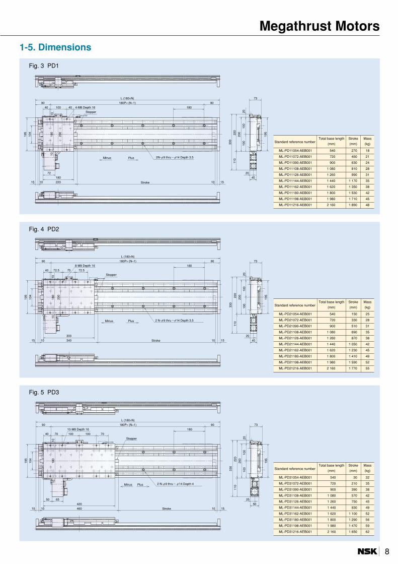
1-5. Dimensions
Fig. 3 PD1
Fig. 4 PD2
Fig. 5 PD3
72.5 75 72.5
90
L (180×N)
90
40
104
20
40
110
330
15 10 340
20022
0
10
10 15
10
100
100
73
195
195
180
180
200
300
20
180P× (N–1)
8-M8 Depth 16
Stopper
Minus Plus 2 N- 9 thru ~ 14 Depth 3.5φ φ
Stroke
70 100 100 70
90
L (180×N)
90
40
104
15 10 460
20022
0
10 15
10
100
50
256550
100
110
330
73
195
195
180
180
420
20
180P× (N–1)
10
10-M8 Depth 16
Stopper
Minus Plus 2 N- 9 thru ~ 14 Depth 4φ φ
Stroke
Standard reference numberTotal base length Stroke Mass
(mm) (mm) (kg)
ML-PD11054-AEB001 540 270 18
ML-PD11072-AEB001 720 450 21
ML-PD11090-AEB001 900 630 24
ML-PD11108-AEB001 1 080 810 28
ML-PD11126-AEB001 1 260 990 31
ML-PD11144-AEB001 1 440 1 170 35
ML-PD11162-AEB001 1 620 1 350 38
ML-PD11180-AEB001 1 800 1 530 42
ML-PD11198-AEB001 1 980 1 710 45
ML-PD11216-AEB001 2 160 1 890 48
Standard reference numberTotal base length Stroke Mass
(mm) (mm) (kg)
ML-PD21054-AEB001 540 150 25
ML-PD21072-AEB001 720 330 28
ML-PD21090-AEB001 900 510 31
ML-PD21108-AEB001 1 080 690 35
ML-PD21126-AEB001 1 260 870 38
ML-PD21144-AEB001 1 440 1 050 42
ML-PD21162-AEB001 1 620 1 230 45
ML-PD21180-AEB001 1 800 1 410 49
ML-PD21198-AEB001 1 980 1 590 52
ML-PD21216-AEB001 2 160 1 770 55
Standard reference numberTotal base length Stroke Mass
(mm) (mm) (kg)
ML-PD31054-AEB001 540 30 32
ML-PD31072-AEB001 720 210 35
ML-PD31090-AEB001 900 390 38
ML-PD31108-AEB001 1 080 570 42
ML-PD31126-AEB001 1 260 750 45
ML-PD31144-AEB001 1 440 930 49
ML-PD31162-AEB001 1 620 1 100 52
ML-PD31180-AEB001 1 800 1 290 56
ML-PD31198-AEB001 1 980 1 470 59
ML-PD31216-AEB001 2 160 1 650 62
8
Megathrust Motors

PM Series1-6. How to butt the PM SeriesButt connection of the PM Series
Longer stroke can be achieved by butting the motor base (stator) for the PM Series. The base length to be butted is the standard baselength (whole-number multiples of 180 mm). A maximum base length of 30 m is available. (Cable length is also available up to amaximum of 30 m.) Butted-type PM Series are shipped from the factory in a base unit.For butting the base, customers are required to carry out simple work such as adjustment of center deviation and parallelism of thelinear guide installed on the base. (A set-up manual for the base is enclosed at shipment.)
Outline of the set-up manual1. Preliminary setting of the base2. Correction of center deviation and adjustment of parallelism of the guide rail3. Fixing the scale track of the linear scale4. Fixing the linear scale along the scale track5. Alignment adjustment of the scale head6. Confirmation of the signal output
* Please apply the linear scale enclosed at shipment.In case the motor is disassembled for transportation, carefully detach it according to the manual. Linear scales can be reused.
Joint of the linear guide rail NSK Linear Guide
Base mounting hole
Slider
Frame A Frame B
Base joint
180 mm (Mounting hole pitch) 90 mm PM Series (Base)
Frame joint
Fig. 6
Instructions for manufacturing a mounting frame for a Megathrust Motor
Mounting frames for Megathrust Motors should preferably be manufactured as an integrated construction and notin separate pieces. In case of separate pieces, any height difference in the frame joint should be minimized toavoid center deviation when mounting the base. Furthermore, the frame joint should not be matched with thebase joint.To prevent any center deviation in the vertical direction, we recommend that the frame joint is shifted from thebase joint by two pitches of the base mounting hole. The base of the Megathrust Motor (PM Series) is made ofaluminum. The frame should be designed to have enough strength to receive motor and load mass since the base itself isnot durable enough to support a large load mass. In particular, the motor can be used at high speed and withpowerful thrust, and consideration should be given to the large reaction force generated by such acceleration.
9

Input power voltage 3-phase AC200V/230V±10% 50/60Hz
Input power capacity 1.8KVA (PD1) 3.4KVA (PD2) 5.0KVA (PD3)
Mass 4.0 kg
Environmental condition (at operation) Temperature 0°C ~ 50°C, Humidity 20% ~ 90% (No condensation), No dust
Entry current Controlled power 15A or less, Main power 30A or less
Leakage current 3.5 mA (Driver unit single piece)
Pulse train input Maximum input pulse frequency: 800 kppsInput pulse type: PLS/MNS system(1)
Input signal Emergency stop, servo on, internal program selection (maximum 64 steps), positioning start,Control input Control input Home return operation start, home position limit switch, jog, jog travel direction
command, integral control off, over travel, analog speed • thrust command (±10 VDC)
Position feedback signalOutput signal format: line driver
Output signal A/B-Phase • Z-phase: depending on scale specificationControl output Driver Unit ready, in position, servo status
Excess position error , soft-thermal over, over travel, control power voltage drop,Protection function position sensor error, magnetic pole sensor error, power module alarm, regeneration error,
main power voltage error, over speedCommunication Serial RS-232C communication, transmission speed: 9 600 bps
1-7. Reference number
The proprietary EDB type Driver Unit has been developed for the Megathrust Motor PM Series. A user-friendly Driver Unit whose features include easy servo gain adjustment through an integrated automatic tuning function, as well as internal program operation and pulse train input and analog inputoperations.
1-8. SpecificationsTable 2 General specifications
Table 3 Function specifications
* (1) The PLS/MNS system can be switched to the pulse/direction system or to the A/B-phase system.
EDB Driver Unit
10
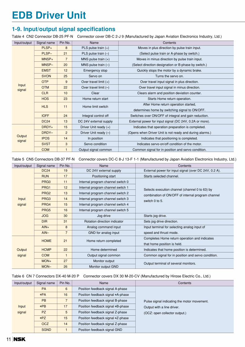
Input/output Signal name Pin No. Name Contents
PLSP+ 8 PLS pulse train (+) Moves in plus direction by pulse train input.
PLSP– 21 PLS pulse train (–) (Select pulse train or A-phase by switch.)
MNSP+ 7 MNS pulse train (+) Moves in minus direction by pulse train input.
MNSP– 20 MNS pulse train (–) (Select direction designation or B-phase by switch.)
EMST 12 Emergency stop Quickly stops the motor by a dynamic brake.
SVON 25 Servo on Turns the servo on.
InputOTP 9 Over travel limit (+) Over travel input signal in plus direction.
OTM 22 Over travel limit (–) Over travel input signal in minus direction.signal
CLR 10 Clear Clears alarm and position deviation counter.
HOS 23 Home return start Starts Home return operation.
HLS 11 Home limit switchAfter Home return operation started,
determines home by switching signal to ON/OFF.
IOFF 24 Integral control off Switches over ON/OFF of integral and gain reduction.
DC24 13 DC 24V external supply External power for input signal (DC 24V, 0.2A or more).
DRDY+ 15 Driver Unit ready (+) Indicates that operation preparation is completed.
OutputDRDY– 2 Driver Unit ready (–) (Opens when Driver Unit is not ready and during alarms.)
IPOS 14 In position Indicates that positioning is completed.signal
SVST 3 Servo condition Indicates servo-on/off condition of the motor.
COM 1 Output signal common Common signal for in position and servo condition.
1-9. Input/output signal specificationsTable 4 CN2 Connector DB-25 PF-N Connector cover DB-C 2-J 9 (Manufactured by Japan Aviation Electronics Industry, Ltd.)
Input/output Signal name Pin No. Name Contents
DC24 19 DC 24V external supply External power for input signal (over DC 24V, 0.2 A).
RUN 17 Positioning start Starts selected channel.
PRG0 11 Internal program channel switch 0
PRG1 12 Internal program channel switch 1Selects execution channel (channel 0 to 63) by
PRG2 13 Internal program channel switch 2combination of ON/OFF of internal program channel
Input PRG3 14 Internal program channel switch 3switch 0 to 5.
signal PRG4 15 Internal program channel switch 4
PRG5 16 Internal program channel switch 5
JOG 30 Jog drive Starts jog drive.
DIR 31 Rotation direction indicator Sets jog drive direction.
AIN+ 8 Analog command input Input terminal for selecting analog input of
AIN– 7 GND for analog input speed and thrust mode.
HOME 21 Home return completedCompletes Home return operation and indicates
that home position is held.
Output HCMP 22 Home determined Indicates that home position is determined.
signal COM 1 Output signal common Common signal for in position and servo condition.
MON+ 27 Monitor outputOutput terminal of several monitors.
MON– 26 Monitor output GND
Table 5 CN5 Connectors DB-37 PF-N Connector covers DC-C 8-J 13-F 1-1 (Manufactured by Japan Aviation Electronics Industry, Ltd.)
EDB Driver Unit
Input/output Signal name Pin No. Name Contents
PA 6 Position feedback signal A-phase
PA 16 Position feedback signal A-phase
PB 7 Position feedback signal B-phase Pulse signal indicating the motor movement.
Input PB 17 Position feedback signal B-phase Output with a line driver.
signal PZ 5 Position feedback signal Z-phase (OCZ: open collector output.) PZ 15 Position feedback signal Z-phase
OCZ 14 Position feedback signal Z-phase
SGND 1 Position feedback signal GND
Table 6 CN 7 Connectors DX-40 M-20 P Connector covers DX 30 M-20-CV (Manufactured by Hirose Electric Co., Ltd.)
11
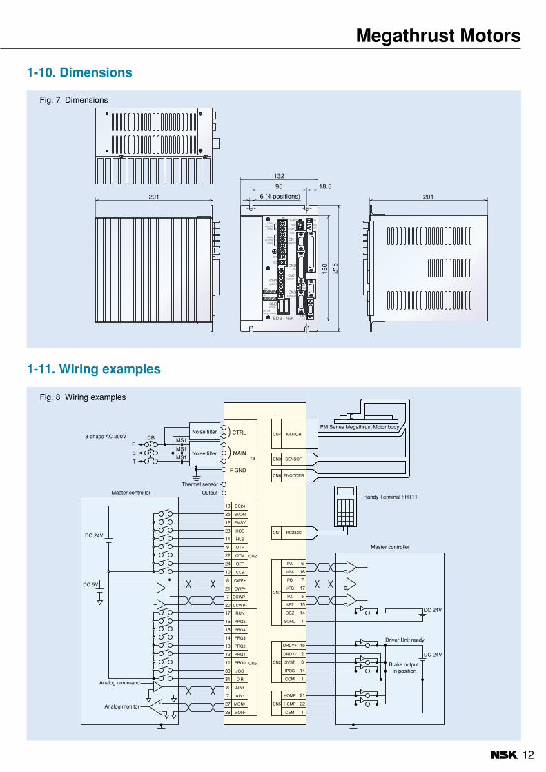
1-10. Dimensions
1-11. Wiring examples
Fig. 7 Dimensions
Fig. 8 Wiring examples
132
18.595
180
215
201201 6 (4 positions)
DC2413
SVON25
EMSY12
HOS23
HLS11
OTP9
OTM22 CN2
OFF24
CLS10
CWP+8
CWP-21
CCWP+7
CCWP-20
RUN17
PRG516
PRG415
PRG314
PRG213
PRG112
PRG011 CN5
JOG30
DIR31
AIN+8
AIN-7
MON+27
MON-26
+
-
21
HCMP
HOME
22
CEM 1
CN5
DC 24V
DC 5V
DRDY+ 15
DRDY- 2
SVST 3
IPOS 14
COM 1
CN2
PB 17
PB 7
PA 16
PA 6
PZ 5
PZ 15
OCZ 14
SGND 1
CN7
DC 24V
DC 24V
F GND
MAIN
CBR
S
T
CTRL
TB
MS1
MS1
MS1 SENSORCN3
ENCODERCN6
MOTORCN4
RC232CCN1
3-phase AC 200V
Master controller
Analog command
Analog monitor
Noise filter
Noise filter
Thermal sensor
Output
PM Series Megathrust Motor body
Handy Terminal FHT11
Driver Unit ready
Brake output In position
Master controller
12
Megathrust Motors
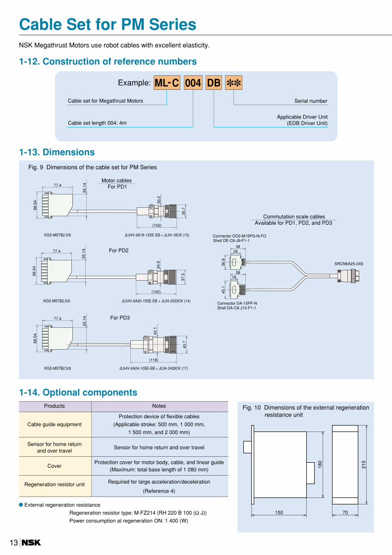
Cable Set for PM Series
1-12. Construction of reference numbers
NSK Megathrust Motors use robot cables with excellent elasticity.
004 ML-C DBExample:
Cable set for Megathrust Motors
Cable set length 004: 4m
Serial number
Applicable Driver Unit(EDB Driver Unit)
JL04V-6A24-10SE-EB + JL04-2428CK (17)
43.7
42.1
(118)
KGS-MSTB2.5/8
55.1
477.4
68.5
4
For PD3
Fig. 9 Dimensions of the cable set for PM Series
1-13. Dimensions
Products Notes
Protection device of flexible cables
Cable guide equipment (Applicable stroke: 500 mm, 1 000 mm,
1 500 mm, and 2 000 mm)
Sensor for home returnSensor for home return and over travel
and over travel
CoverProtection cover for motor body, cable, and linear guide
(Maximum: total base length of 1 080 mm)
Regeneration resistor unit Required for large acceleration/deceleration
(Reference 4)
1-14. Optional components
External regeneration resistance
Regeneration resistor type: M-FZ214 (RH 220 B 100 (Ω J))
Power consumption at regeneration ON: 1 400 (W)
150 70
180
215
Fig. 10 Dimensions of the external regenerationresistance unit
35.7
30.2
JL04V-6A18-12SE-EB + JL04-18CK (13)KGS-MSTB2.5/8
55.1
477.4
68.5
4
(102)
Motor cables For PD1
36.8
2638
1838
45.1
SRCN6A25-24S
Commutation scale cablesAvailable for PD1, PD2, and PD3
Connector DO2-M15PG-N-FOShell DE-C8-J9-F1-1
Connector DA-15PF-NShell DA-C8-J10-F1-1
37.3
(102)
34.9
JL04V-6A20-15SE-EB + JL04-2022CK (14)KGS-MSTB2.5/8
55.1
477.4
68.5
4
For PD2
13
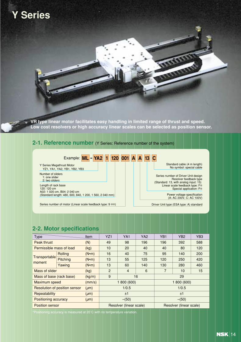
Y Series
VR type linear motor facilitates easy handling in limited range of thrust and speed.Low cost resolvers or high accuracy linear scales can be selected as position sensor.
14
Type Item YZ1 YA1 YA2 YB1 YB2 YB3
Peak thrust (N) 49 98 196 196 392 588
Permissible mass of load (kg) 10 20 40 40 80 120
TransportableRolling (N•m) 16 40 75 95 140 200
Pitching (N•m) 13 55 125 120 250 420moment
Yawing (N•m) 13 60 140 130 280 460
Mass of slider (kg) 2 4 6 7 10 15
Mass of base (rack base) (kg/m) 9 16 29
Maximum speed (mm/s) 1 800 (600) 1 800 (600)
Resolution of position sensor (µm) 1/0.5 1/0.5
Repeatability (µm) ±1 ±1
Positioning accuracy (µm) –(50) –(50)
Position sensor Resolver (linear scale) Resolver (linear scale)
2-2. Motor specifications
2-1. Reference number (Y Series: Reference number of the system)
1 120 13001 AA CYA2MLExample:
Y Series Megathrust Motor YZ1, YA1, YA2, YB1, YB2, YB3
Number of sliders1: one slider2: two sliders
Length of rack base 120: 120 cmA02: 1 020 cm, B04: 2 040 cm(Standard length: 480, 600, 840, 1 200, 1 560, 2 040 mm)
Series number of motor (Linear scale feedback type: 9 )
Standard cable (4 m length)No symbol: special cable
Series number of Driver Unit designResolver feedback type
(Standard: 13, with analog input: 15) Linear scale feedback type: F
Special application: F
Power voltage specification(A: AC 200V, C: AC 100V)
Driver Unit type (ESA type: A) standard
*Positioning accuracy is measured at 20˚C with no temperature variation.

2-4. Effective strokeSix types of length (480 mm to 2 040 mm) are available for the standard rack base of the Megathrust Motor Y Series. The effective
stroke per each motor to the length of rack base is shown in Table 7. The stroke can be extended by the butting method, except for
types YZ1, YA1, and YB1. In this system, three types of standard rack base (1 200, 1 560, and 2 040 mm) are combined for a rack
base of length of 2 040 mm or more.
Motor type Base Combination BaseYZ1 YA1 YA2 YB1 YB2 YB3 length of bases specifications
310 310 205 310 205 100 480 420 × 1
430 430 325 430 325 220 600 600 × 1Integrated type
Effective stroke670 670 565 670 565 460 840 840 × 1
rack base1 030 1 030 925 1 030 925 820 1 200 1 200 × 1
specifications1 390 1 390 1 285 1 390 1 285 1 180 1 560 1 560 × 1
– 1 870 1 765 1 870 1 765 1 660 2 040 2 040 × 1
Table 7 Effective stroke
Notes : Lengths not stated in this table are also available. Please contact NSK for details.Linear motors capable for long stroke are delivered with separate rack bases. Customers can simply assemble according to the set up manualfor the base included with the motors. All assembly is to be carried out by the customer.
Unit: mm
Y Series2-3. Properties of speed and thrust
Fig. 11 Properties of speed and thrust
0
100
YA2
YA1
YZ1
200
1.81.20.6
YZ , YA (Resolver feedback type)
Power voltage AC 200V
Power voltage AC 100V
Slid
er th
rust
, N
Slider speed, m/s
0
100
300
400
500
600
700
200
1.81.20.6
YB1
YB2YB3
Power voltage AC 200V
Power voltage AC 100V
Slid
er th
rust
, N
Slider speed, m/s
YB (Resolver feedback type)
0 0.6
YA2
YA1
YZ1
100
200
YZ , YA (Linear scale feedback type)
Power voltage AC 200V
Power voltage AC 100V
Slid
er th
rust
, N
Slider speed, m/s
0 0.6
100
300
400
500
600
700
200 YB1
YB2
YB3
YB (Linear scale feedback type)
Power voltage AC 200V
Power voltage AC 100V
Slid
er th
rust
, N
Slider speed, m/s
15
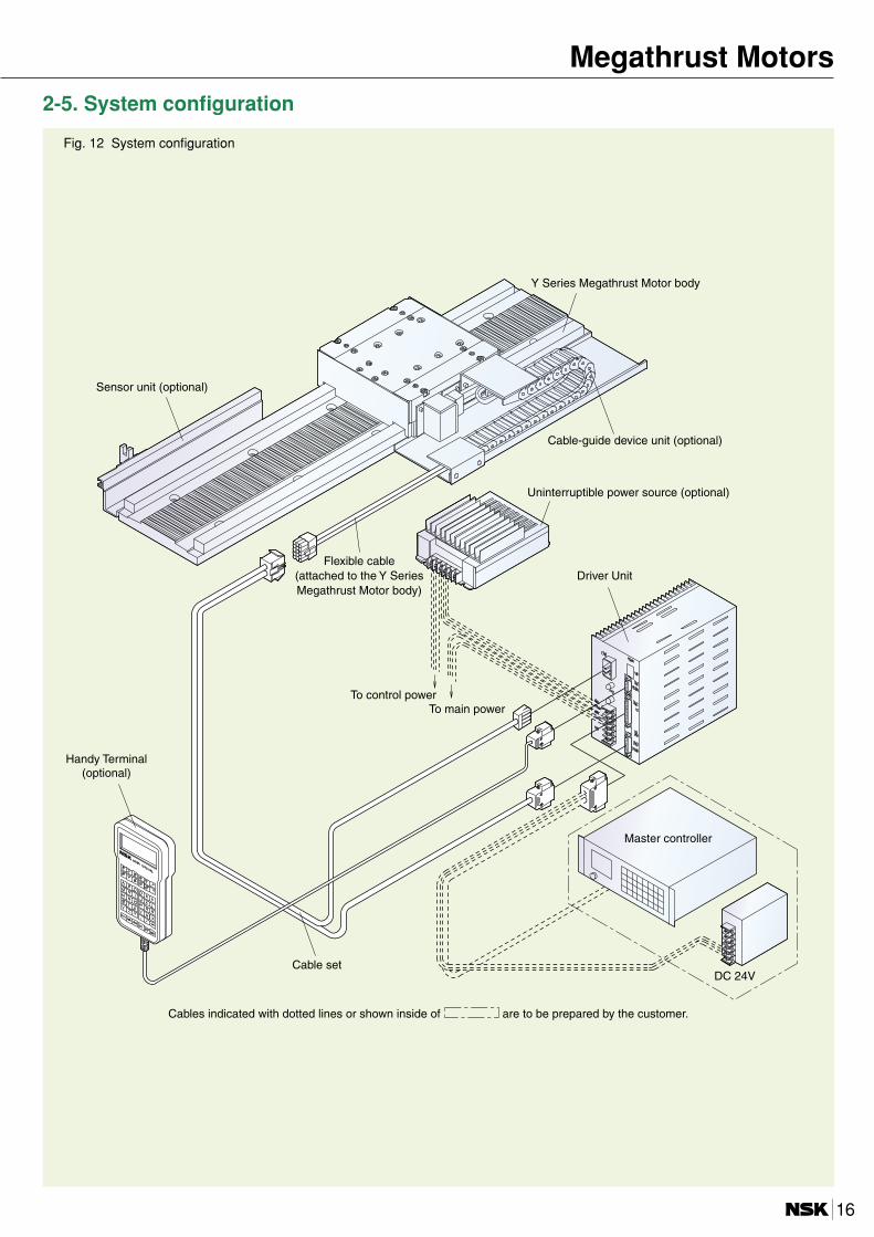
2-5. System configuration
Fig. 12 System configuration
DC 24V
Y Series Megathrust Motor body
Sensor unit (optional)
Cable-guide device unit (optional)
Uninterruptible power source (optional)
Flexible cable(attached to the Y SeriesMegathrust Motor body)
To control powerTo main power
Handy Terminal(optional)
Master controller
Cable set
Driver Unit
Cables indicated with dotted lines or shown inside of are to be prepared by the customer.
16
Megathrust Motors

Y Series2-6. Dimensions
Fig. 13 YZ1 Resolver feedback type
Fig. 14 YA1 Resolver feedback type
Fig. 15 YA2 Resolver feedback type
Reference number of motor Stroke (mm) L (mm) Mass (kg)
ML-TZ11048001 310 480 6.5
ML-TZ11060001 430 600 7.5
ML-TZ11084001 670 840 9.5
ML-TZ11120001 1 030 1 200 13
ML-TZ11156001 1 390 1 560 16
Reference number of motor Stroke (mm) L (mm) Mass (kg)
ML-YA11048001 310 480 12
ML-YA11060001 430 600 14
ML-YA11084001 670 840 18
ML-YA11120001 1 030 1 200 23.5
ML-YA11156001 1 390 1 560 29
ML-YA11204001 1 870 2 040 37
Reference number of motor Stroke (mm) L (mm) Mass (kg)
ML-YA21048001 205 480 14
ML-YA21060001 325 600 16
ML-YA21084001 565 840 20
ML-YA21120001 925 1 200 25.5
ML-YA21156001 1 285 1 560 31
ML-YA21204001 1 765 2 040 39
17

2-7. Dimensions
Fig. 16 YZ1 Linear scale feedback type
Fig. 17 YA1 Linear scale feedback type
Fig. 18 YA 2 Linear scale feedback type
120120P × N = 120N60
L 44
4517
10.5
96
555515510
510
1170
15
98.5
36.5
67
15025
189
1 40
7573
30.5
7.5
36.5
60
L-20 (Length of NSK Linear Guide)Stroke
Minus Plus
Mounting tap for users, heli-coil 6-M5×0.8 Depth 7.5Head cable
Motor cableMounting hole of fixed part 5.5 thru 9.5 Depth 15φ φ Slider
M3×0.5 Depth 6 (Tap hole position is in phase with mounting holes of fixed part.)
Detective headMain scale
Head cable length(stroke/2 + 500 mm)
Motor cable length(stroke/2 + 500 mm)
70140
25.5
9.5
14086 2727
106
120
2525
90
6060
1717
510
510
44120P × N = 120N
L
35.5
8482
64
4514
0.5
5423
0
4010
7.5
30.5
L-20 (Length of NSK Linear Guide)Stroke
Minus Plus
Mounting hole of fixed part 6.6 thru 11 Depth 15φ φ
M3×0.5 Depth 6 (Tap hole position is in phase with mounting holes of fixed part.)
Head cable
Motor cableSlider
Detective headMain scale
Head cable length(stroke/2 + 500 mm)
Motor cable length(stroke/2 + 500 mm)
Mounting tap for users, heli-coil 4-M6×1.0 Depth 12
70140
25.5
9.5
106
120
2525
90
6060
1717
510
510
44120P × N = 120N
L
35.5
8482
64
4514
0.5
5423
0
4010
7.5
30.5
24533 179 33
L-20 (Length of NSK Linear Guide)Stroke
Minus Plus
Mounting tap for users, heli-coil 4-M6×1.0 Depth 12
M3×0.5 Depth 6 (Tap hole position is in phase with mounting holes of fixed part.)
Mounting hole of fixed part 6.6 thru 11 Depth 15φ φ Slider
Head cable
Motor cable
Detective headMain scale
Head cable length(stroke/2 + 500 mm)
Motor cable length(stroke/2 + 500 mm)
Reference number of motor Stroke (mm) L (mm) Mass (kg)
ML-YZ11048901 300 480 15.5
ML-YZ11060901 420 600 19
ML-YZ11084901 660 840 26
ML-YZ11120901 1 020 1 200 36
ML-YZ11156901 1 380 1 560 46
Reference number of motor Stroke (mm) L (mm) Mass (kg)
ML-YA11048901 310 480 24
ML-YA11060901 430 600 29
ML-YA11084901 670 840 39
ML-YA11120901 1 030 1 200 54
ML-YA11156901 1 390 1 560 69
Reference number of motor Stroke (mm) L (mm) Mass (kg)
ML-YA21048901 205 480 26
ML-YA21060901 325 600 31
ML-YA21084901 565 840 41
ML-YA21120901 925 1 200 56
ML-YA21156901 1 285 1 560 71
18
Megathrust Motors

Y Series2-8. Dimensions
Fig. 19 YB1 Resolver feedback type
Fig. 20 YB2 Resolver feed back type
Fig. 21 YB3 Resolver feedback type
Reference number of motor Stroke (mm) L (mm) Mass (kg)
ML-YB11048001 310 480 21
ML-YB11060001 430 600 24.5
ML-YB11084001 670 840 31.5
ML-YB11120001 1 030 1 200 42
ML-YB11156001 1 390 1 560 52.5
ML-YB11204001 1 870 2 040 66.5
Reference number of motor Stroke (mm) L (mm) Mass (kg)
ML-YB21048001 205 480 24
ML-YB21060001 325 600 27.5
ML-YB21084001 565 840 34.5
ML-YB21120001 925 1 200 45
ML-YB21156001 1 285 1 560 55.5
ML-YB21204001 1 765 2 040 69.5
Reference number of motor Stroke (mm) L (mm) Mass (kg)
ML-YB31048001 100 480 29
ML-YB31060001 220 600 32.5
ML-YB31084001 460 840 39.5
ML-YB31120001 820 1 200 50
ML-YB31156001 1 180 1 560 60.5
ML-YB31204001 1 660 2 040 74.5
19
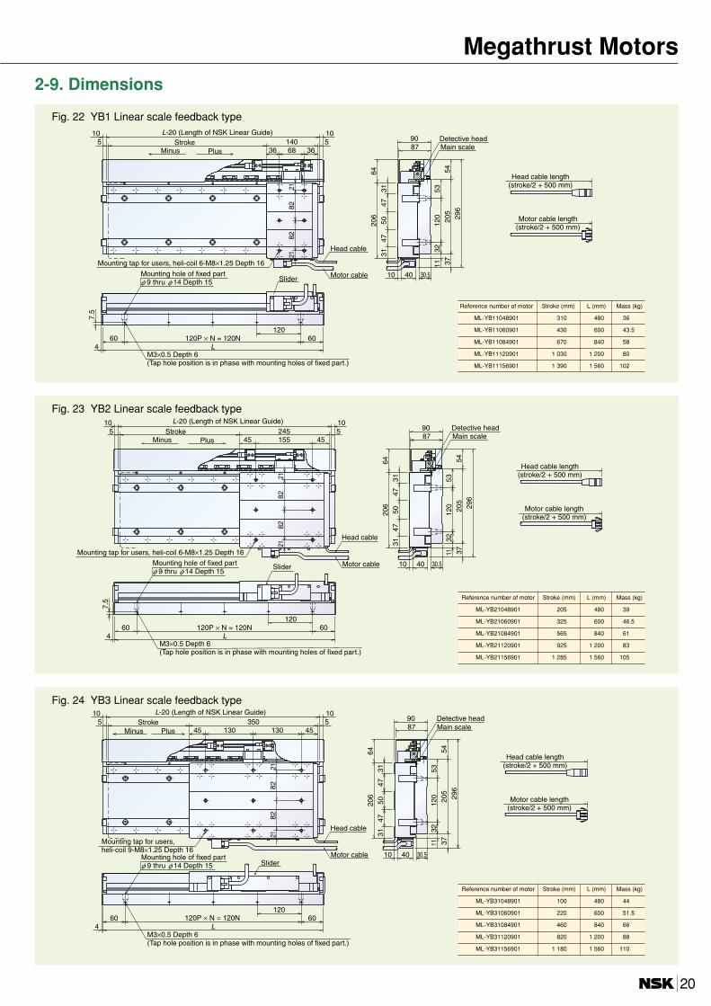
2-9. Dimensions
Fig. 22 YB1 Linear scale feedback type
Fig. 23 YB2 Linear scale feedback type
Fig. 24 YB3 Linear scale feedback type
12060120P × N = 120N60
L
5312
032
205
8790
54
5
296
37
5
3147
5047
3120
664
1010
10 40
4
30.5
7.5
11
140
2182
8221
366836
L-20 (Length of NSK Linear Guide)Stroke
Minus Plus
Mounting tap for users, heli-coil 6-M8×1.25 Depth 16
Mounting hole of fixed part 9 thru 14 Depth 15φ φ Slider
M3×0.5 Depth 6 (Tap hole position is in phase with mounting holes of fixed part.)
Head cable
Motor cable
Detective headMain scale
Head cable length(stroke/2 + 500 mm)
Motor cable length(stroke/2 + 500 mm)
Reference number of motor Stroke (mm) L (mm) Mass (kg)
ML-YB11048901 310 480 36
ML-YB11060901 430 600 43.5
ML-YB11084901 670 840 58
ML-YB11120901 1 030 1 200 80
ML-YB11156901 1 390 1 560 102
Reference number of motor Stroke (mm) L (mm) Mass (kg)
ML-YB21048901 205 480 39
ML-YB21060901 325 600 46.5
ML-YB21084901 565 840 61
ML-YB21120901 925 1 200 83
ML-YB21156901 1 285 1 560 105
Reference number of motor Stroke (mm) L (mm) Mass (kg)
ML-YB31048901 100 480 44
ML-YB31060901 220 600 51.5
ML-YB31084901 460 840 66
ML-YB31120901 820 1 200 88
ML-YB31156901 1 180 1 560 110
20
Megathrust Motors
Motor type YA2 YB2 YB3 Total length of rack base (L) Combination of rack base
2 125 2 125 2 020 2 400 1 200 × 2
2 845 2 845 2 740 3 120 1 560 × 2
3 325 3 325 3 220 3 600 (1 560 × 1) + (2 040 × 1)
3 805 3 805 3 700 4 080 2 040 × 2
Effective stroke4 885 4 885 4 780 5 160 (1 560 × 2) + (2 040 × 1)
5 845 5 845 5 740 6 120 2 040 × 3
6 925 6 925 6 820 7 200 (1 560 × 2) + (2 040 × 2)
7 885 7 885 7 780 8 160 2 040 × 4
8 965 8 965 8 860 9 240 (1 560 × 2) + (2 040 × 3)
9 925 9 925 9 820 10 200 2 040 × 5
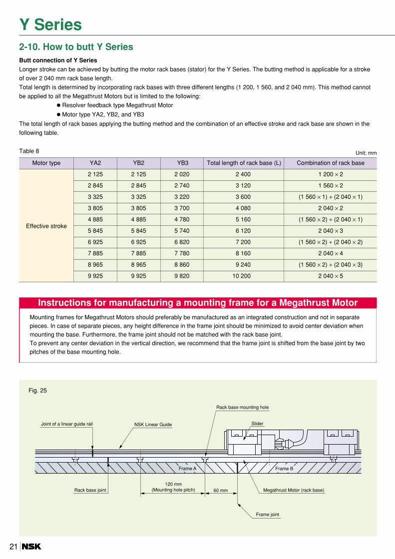
2-10. How to butt Y SeriesButt connection of Y Series
Longer stroke can be achieved by butting the motor rack bases (stator) for the Y Series. The butting method is applicable for a stroke
of over 2 040 mm rack base length.
Total length is determined by incorporating rack bases with three different lengths (1 200, 1 560, and 2 040 mm). This method cannot
be applied to all the Megathrust Motors but is limited to the following: Resolver feedback type Megathrust Motor
Motor type YA2, YB2, and YB3
The total length of rack bases applying the butting method and the combination of an effective stroke and rack base are shown in the
following table.
Table 8 Unit: mm
Joint of a linear guide rail NSK Linear Guide
Rack base mounting hole
Slider
Frame A Frame B
Rack base joint120 mm
(Mounting hole pitch) 60 mm Megathrust Motor (rack base)
Frame joint
Fig. 25
Instructions for manufacturing a mounting frame for a Megathrust MotorMounting frames for Megathrust Motors should preferably be manufactured as an integrated construction and not in separatepieces. In case of separate pieces, any height difference in the frame joint should be minimized to avoid center deviation whenmounting the base. Furthermore, the frame joint should not be matched with the rack base joint.To prevent any center deviation in the vertical direction, we recommend that the frame joint is shifted from the base joint by twopitches of the base mounting hole.
Y Series
21
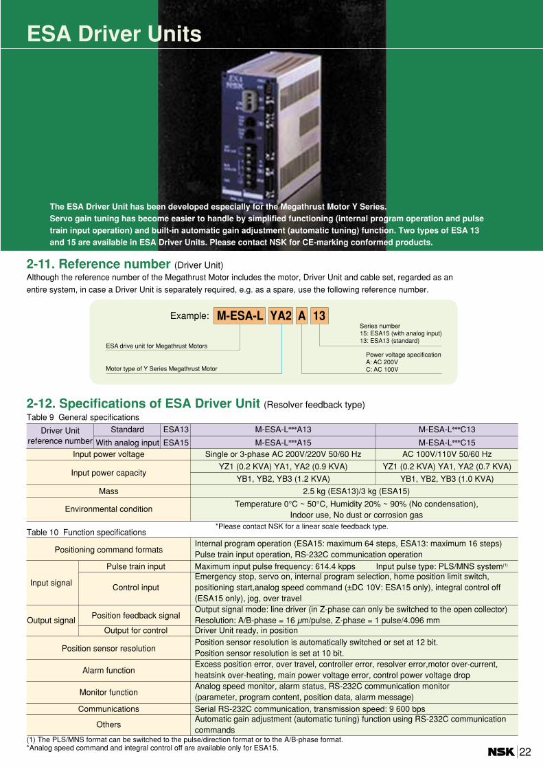
2-11. Reference number (Driver Unit)
The ESA Driver Unit has been developed especially for the Megathrust Motor Y Series. Servo gain tuning has become easier to handle by simplified functioning (internal program operation and pulsetrain input operation) and built-in automatic gain adjustment (automatic tuning) function. Two types of ESA 13and 15 are available in ESA Driver Units. Please contact NSK for CE-marking conformed products.
ESA Driver Units
AYA2M-ESA-L 13Example:
ESA drive unit for Megathrust Motors
Motor type of Y Series Megathrust Motor
Series number15: ESA15 (with analog input)13: ESA13 (standard)
Power voltage specificationA: AC 200VC: AC 100V
Although the reference number of the Megathrust Motor includes the motor, Driver Unit and cable set, regarded as an
entire system, in case a Driver Unit is separately required, e.g. as a spare, use the following reference number.
Driver Unit Standard ESA13 M-ESA-LA13 M-ESA-LC13reference number With analog input ESA15 M-ESA-LA15 M-ESA-LC15
Input power voltage Single or 3-phase AC 200V/220V 50/60 Hz AC 100V/110V 50/60 Hz
Input power capacityYZ1 (0.2 KVA) YA1, YA2 (0.9 KVA) YZ1 (0.2 KVA) YA1, YA2 (0.7 KVA)
YB1, YB2, YB3 (1.2 KVA) YB1, YB2, YB3 (1.0 KVA)
Mass 2.5 kg (ESA13)/3 kg (ESA15)
Environmental conditionTemperature 0°C ~ 50°C, Humidity 20% ~ 90% (No condensation),
Indoor use, No dust or corrosion gas
2-12. Specifications of ESA Driver Unit (Resolver feedback type)Table 9 General specifications
*Please contact NSK for a linear scale feedback type.
Positioning command formatsInternal program operation (ESA15: maximum 64 steps, ESA13: maximum 16 steps)Pulse train input operation, RS-232C communication operation
Pulse train input Maximum input pulse frequency: 614.4 kpps Input pulse type: PLS/MNS system(1)
Input signalEmergency stop, servo on, internal program selection, home position limit switch,
Control input positioning start,analog speed command (±DC 10V: ESA15 only), integral control off (ESA15 only), jog, over travel
Position feedback signalOutput signal mode: line driver (in Z-phase can only be switched to the open collector)
Output signal Resolution: A/B-phase = 16 µm/pulse, Z-phase = 1 pulse/4.096 mmOutput for control Driver Unit ready, in position
Position sensor resolutionPosition sensor resolution is automatically switched or set at 12 bit.Position sensor resolution is set at 10 bit.
Alarm functionExcess position error, over travel, controller error, resolver error,motor over-current,heatsink over-heating, main power voltage error, control power voltage drop
Monitor functionAnalog speed monitor, alarm status, RS-232C communication monitor(parameter, program content, position data, alarm message)
Communications Serial RS-232C communication, transmission speed: 9 600 bps
OthersAutomatic gain adjustment (automatic tuning) function using RS-232C communication commands
Table 10 Function specifications
(1) The PLS/MNS format can be switched to the pulse/direction format or to the A/B-phase format. *Analog speed command and integral control off are available only for ESA15. 22

2-14. Specifications of type ESA 13 input/output signal
Input/output Signal name Pin No. Name Contents
PLSP+ 8 PLS pulse train (+) Moves in plus direction by pulse train input.
PLSP– 21 PLS pulse train (–) (Select pulse train or A-phase by switch.)
MNSP+ 7 MNS pulse train (+) Moves in minus direction by pulse train input.
MNSP– 20 MNS pulse train (–) (Select direction designation or B-phase by switch.)
EMST 12 Emergency stop Quickly stops the motor by a dynamic brake.
SVON 25 Servo on Turns the servo on.
Input OTP 9 Over travel limit (+) Over travel input signal in plus direction.
OTM 22 Over travel limit (–) Over travel input signal in minus direction.signalCLR 10 Clear Clears alarm and position deviation counter.
HOS 23 Home return start Starts Home return operation.
After Home return operation started,HLS 11 Home limit switch
determines home by switching signal to ON/OFF.
RUN 24 Positioning start Starts selected channel.
DC24 13 DC 24V external supply External power for input signal (over DC 24V, 0.2 A).
CHA 6 Position feedback signal A-phaseCHA 19 Position feedback signal A-phase
CHB 5 Position feedback signal B-phase Pulse signal indicating the motor movement.
CHB 18 Position feedback signal B-phase Output with a line driver.
OutputCHZ 4 Z-phase position feedback signal MSB (OCZ: open collector output.)
CHZ 17 Position feedback signal Z-phasesignal SGND 16 Signal ground for position feedback signal
DRDY+ 15 Driver Unit ready (+) Indicates that operation preparation is completed.
DRDY– 2 Driver Unit ready (–) (Opens when drive unit is not ready and during alarms.)
IPOS 14 In position Indicates that positioning is completed.— 3 — —
COM 1 Output signal common Common signal for in position and servo condition.
*The signal of pin No. 10 and 23 can be changed by setting changes from the RS-232C as follows:
Input RPG2 10 Internal program channel switch 2 Selects the execution channel by combination of ON/OFFSignal RPG3 23 Internal program channel switch 3 of the channel switches 2 and 3.
Y Series
DC2413
SVON25
EMST12
MLS11
RUN24
OTP9
OTM22
DRDY+ 15
DRDY- 2
– 3
IPOS 14
COM 1
CN2
CN2
RS-232CCN1
F GND
MAIN
DC 24V
DC 24VDC 5V
CBR
S
T
CONT
SENSORCN3TB
MOTORCN4
CLR10
HOS23
PLSP+8
PLSP-21
MNSP+7
MNSP-20
MS1
MS1
MS1
3-phase AC 200Vor single phase
AC 200V, AC 100V
Noise filter
Noise filter
Y Series Megathrust Motor body
Handy TerminalFHT11
Servo onEmergency stopHome limit switchPositioning startOver travel (+) Over travel (–)
ClearHome return operation start
MNS pulse train
MNS pulse train
Driver Unit ready
In position
Master controller
Master controller
ESA13
2-13. Wiring example of ESA 13
Table 10 CN 2 Connectors DB-25PF-N Connector covers DB-C 2-J 9 (Manufactured by Japan Aviation Electronics Industry, Ltd.)
23

2-15. Wiring example of ESA 15
SENSORCN3
MOTORCN4
RS-232CCN1
DC2413
SVON25
EMSY12
HOS23
HLS11
OTP9
OTM22 CN2
OFF24
CLS10
CWP+8
CWP-21
CCWP+7
CCWP-20
RUN17
PRG516
PRG415
PRG314
PRG213
PRG112
PRG011 CN5
JOG30
DIR31
AIN+8
AIN-7
MON+27
MON-26
+
-
21
HCMP
HOME
22
CEM 1
CN5
DC 24V
DC 5V
DRDY+ 15
DRDY- 2
SVST 3
IPOS 14
COM 1
CN2
DC 24V
F GND
MAIN
CBR
S
T
CONT
TB
MS1
MS1
MS1
3-phase AC 200V Noise filter
Noise filter
Y Series Megathrust Motor body
Master controller
Analog command
Analog monitor
Handy TerminalFHT11
Master controller
Driver Unit ready
Brake output In position
ESA15
2-16. Dimensions
NSK Ltd. MADE IN JAPAN
170
180
215
8550
POWER
DISP.
CN1
CN2
CN3
CN4 RS
-232C
I/O
SE
NS
OR
VEL.GND
FGND
MOTOR
CONT.AC90-220V
MAINAC200-220V
FUSE1250V10AFUSE2250V10A
R
S
T
Type No.
17.5
17.5
6
ESA13 ESA15
24
170
CN5I/O2
VR1MON.GND
180
215
1058550
8.5
POWER
DISP.
CN1
CN2
CN3
CN4 RS
-232C
I/O
SE
NS
OR
VEL.GND
FGND
MOTOR
CONT.AC90-220V
MAINAC200-220V
FUSE1250V10AFUSE2250V10A
R
S
T
Type No.
NSK Ltd. MADE IN JAPAN
17.5
17.5
6
Megathrust Motors

Cable sets for Y Series
2-18. Dimensions
Fig. 26 Dimensions of cable sets for Y Series
2-17. Reference number
NSK Megathrust Motors use robot cables with excellent elasticity.
005 05ML-C MSExample:
Cable set for Megathrust Motors
Cable set length
005: 5m
Series number
Applicable Driver Unit
MS: For ESA Driver Unit
2-19. Optional uninterruptable power source (Reference number: M-FZ 041) (specially for Y Series)
This uninterruptable power source is used to provide an electronic brake function. If the power is connected to a Megathrust Motor,braking force occurs without mechanical equipment when power fails. However, since the braking force is only generated in about two seconds after power fails, it cannot be used for negative braking of theupper and lower axes. The applicable range of the uninterruptable power source is shown in Fig. 27. YB3 using the EDA Driver Unitwith 200V main power voltage (mass of slider: 15 kg), when 85 kg mass of load and 100 kg total mass are driven at 0.6 m/s, the brakeaction can function within the range in Fig. 27. However, when the mass of load of the same 85 kg is driven at 1 m/s, the brakingaction cannot function out of the range of . In such cases, alternative braking mechanisms have to be studied.
00.0
0.2
0.4
0.6
0.8
1.0
1.2
1.4
1.6
1.8
2.0
20 40 60 80 100 120
Applicable range
Mass of slider + mass of load, kg
Spe
ed, m
/s
Main power 100VMain power 200V
Approximate braking distance is obtained by the following formula.
Braking distance L =1
V 2m
2 F
Where, V: Usable speed (m/s)m:Total mass of moving part including mass of slider (kg)F: Braking force classified by motor type
(please refer to Table 10)
Motor type Braking force F (N)
YZ1 50
YA1 100
YA2 200
YB1 170
YB2 330
YB3 500
Table 11 Braking force classified by motor type
Fig. 27 ESA Driver Unit
25

The Handy Terminal FHT-11 is a communication
terminal for the Driver Unit, using an RS-232C
interface.
This terminal can be easily used by simply
connecting it to the CN1 connector.
Easily-viewable LCD screen displays 4 lines
of 20 characters each
No external power required
A wide range of characters can be handled
(Alphanumeric + special characters in
conformity with ASCII code)
Reference number: M-FHT11
Handy Terminal
Power voltage DC 5V ±5%
Power consumption 200 mW
Applicable ambient temperature 0 ~ 50 ˚C
Applicable ambient humidity 35 ~ 85% RH (No freeze)
Applicable ambient atmosphere No corrosive gas
Storage ambient temperature –10 ~ +65 ˚C
Transmission speed: 9 600 bps
RS-232C communication Data bit: 8 bit
Stop bit: 2 bitspecifications Start bit: 1 bit
Parity check: No
Transfer data ASCII code
Usable connectorDE-9 P-N (Manufactured by Japan Aviation
Electronics Industry, Ltd.)
Fitting coverDE-CI-J6 (Manufactured by Japan Aviation
Electronics Industry, Ltd.)
Body mass Approx. 250g (Excluding cables)
Terminal number 1 2 3 4 5 6 7 8 9
Signal code RXD RTS TXD DTR DSR SG CTS +5V FG
1. Specifications
3. Arrangement of connector pins (DE-9 P-N use)
2. Shape and dimensions
Available for PM Series and Y Series
26
Megathrust Motors