medicinal leech electrophysiology: retzius readings€¦ · medicinal leech electrophysiology:...
TRANSCRIPT

Hannah Liechty
A09522659
May 22, 2014
Phys 173
Spring 2014
Medicinal Leech Electrophysiology: Retzius Readings
Introduction
Initially when this lab began, the idea was to be able to set up a system that would allow
two electrodes to be placed into two different cells from a fresh leech ganglion and measure the
effect of stimulus into one cell on another cell to understand the complex interactions that occur
within the ganglion. Yet many difficulties arose such as lighting, focus, issues with the amplifier
and the probes, and lack of time to practice probing cells other than the Retzius cell. Finally a
reading of the Retzius cell was obtained as seen in figure 4 with periodic pulses for 10 seconds
averaging about 1 pulse per second.
Experimental Procedure
Solutions Preparation
In order to properly conduct basic electrophysiology of the leech ganglion two solutions
were prepared, saline and potassium chloride/potassium acetate. The saline solution (aka instant
ocean) was made with the following salts per liter of solution:
mM Composition g/L g/6L g/2L
115 NaCl 6.71 40.26 13.42
4 KCl 0.30 1.80 0.60
1.8 CaCl2 * 2H2O 0.27 1.62 0.54
1.5 MgCl2 * 6H2O 0.30 1.80 0.60
10 Glucose 1.80 10.80 3.60
10 Tris 1.58 9.46 3.16
This was used as a frozen mixture along with the liquid form to transport the leech and conduct
the “wet” dissection. Then the potassium chloride/potassium acetate solution was made with
20mM potassium chloride in 1M potassium acetate which was used in the micropipette as an
electrolyte pathway for the silver chloride-coated electrode.
Leech Preparation
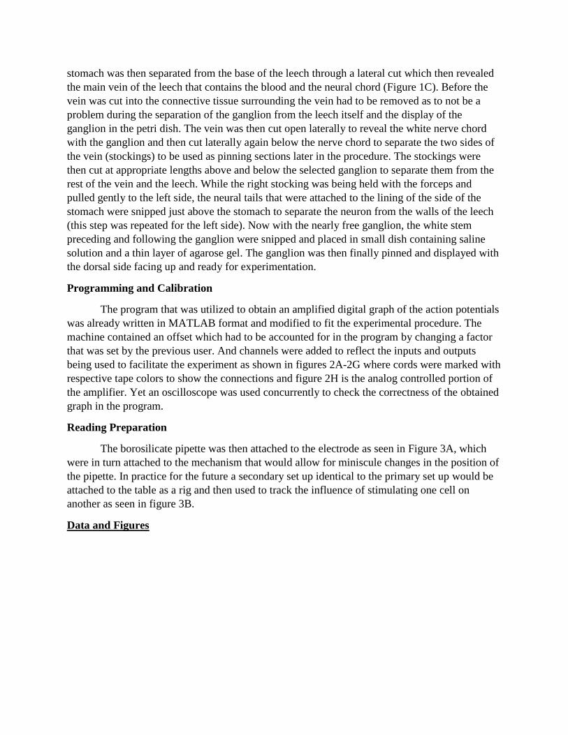
Leeches were first obtained from the Kristan Lab then placed in a cold dissection tray as
shown in Figure 1A with saline solution. The smaller end of the leech is the “head” where it was
pinned to one end of the wax and the large end with the sucker was pinned and stretched to the
opposite end. Then using a small scalpel (obtained from Kristan Lab) the leech was fillet open in
a zipper-like fashion while being careful to not prod the scalpel too deep as to not damage the
ganglia. Then using the smaller pins, the epithelia of the leech was pinned open at intervals of
~1in to reveal the internal structure of the leech as shown in Figure 1B. The lining of the
stomach was then separated from the base of the leech through a lateral cut which then revealed
the main vein of the leech that contains the blood and the neural chord (Figure 1C). Before the
vein was cut into the connective tissue surrounding the vein had to be removed as to not be a
problem during the separation of the ganglion from the leech itself and the display of the
ganglion in the petri dish. The vein was then cut open laterally to reveal the white nerve chord
with the ganglion and then cut laterally again below the nerve chord to separate the two sides of
the vein (stockings) to be used as pinning sections later in the procedure. The stockings were
then cut at appropriate lengths above and below the selected ganglion to separate them from the
rest of the vein and the leech. While the right stocking was being held with the forceps and
pulled gently to the left side, the neural tails that were attached to the lining of the side of the
stomach were snipped just above the stomach to separate the neuron from the walls of the leech
(this step was repeated for the left side). Now with the nearly free ganglion, the white stem
preceding and following the ganglion were snipped and placed in small dish containing saline
solution and a thin layer of agarose gel. The ganglion was then finally pinned and displayed with
the dorsal side facing up and ready for experimentation.
Programming and Calibration
The program that was utilized to obtain an amplified digital graph of the action potentials
was already written in MATLAB format and modified to fit the experimental procedure. The
machine contained an offset which had to be accounted for in the program by changing a factor
that was set by the previous user. And channels were added to reflect the inputs and outputs
being used to facilitate the experiment as shown in figures 2A-2G where cords were marked with
respective tape colors to show the connections and figure 2H is the analog controlled portion of
the amplifier. Yet an oscilloscope was used concurrently to check the correctness of the obtained
graph in the program.
Reading Preparation
The borosilicate pipette was then attached to the electrode as seen in Figure 3A, which
were in turn attached to the mechanism that would allow for miniscule changes in the position of
the pipette. In practice for the future a secondary set up identical to the primary set up would be
attached to the table as a rig and then used to track the influence of stimulating one cell on
another as seen in figure 3B.
Data and Figures
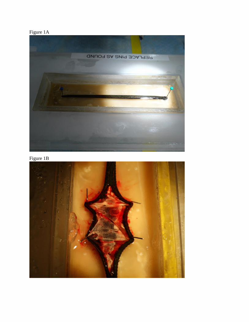
Figure 1A
Figure 1B
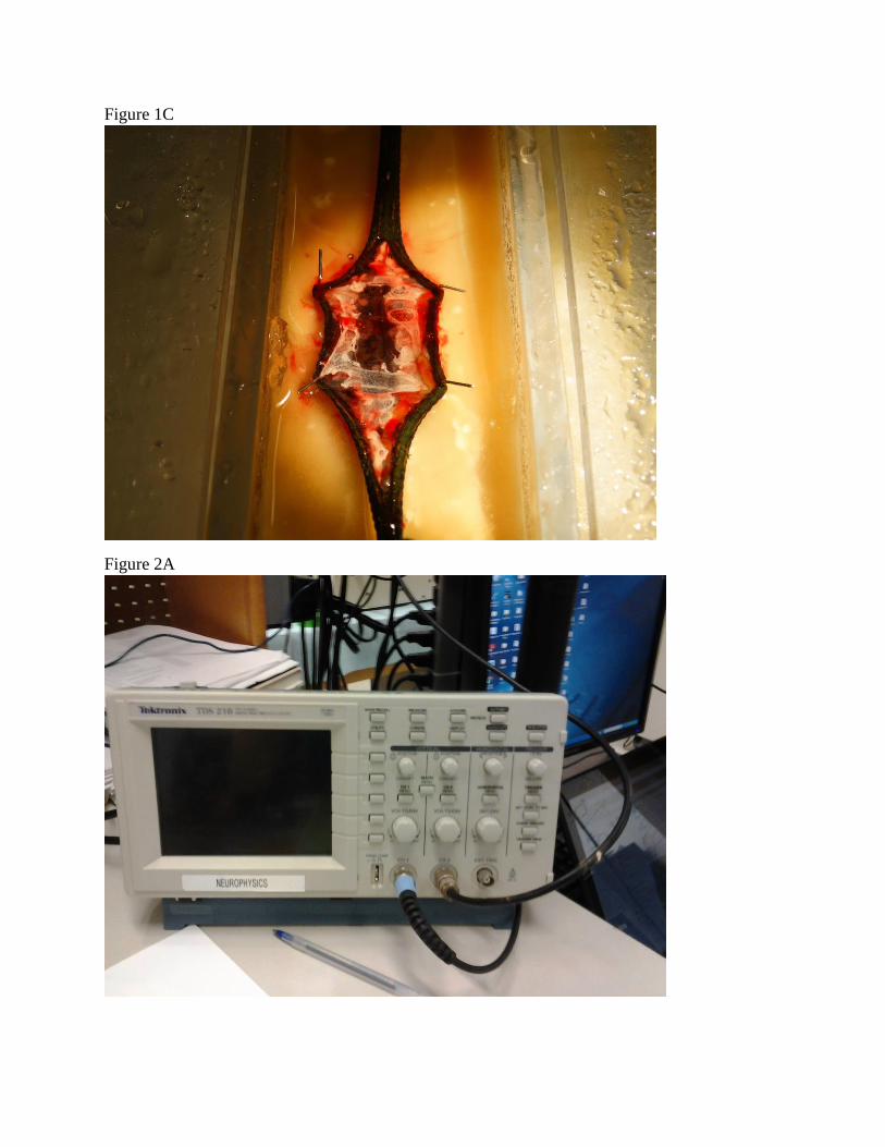
Figure 1C
Figure 2A
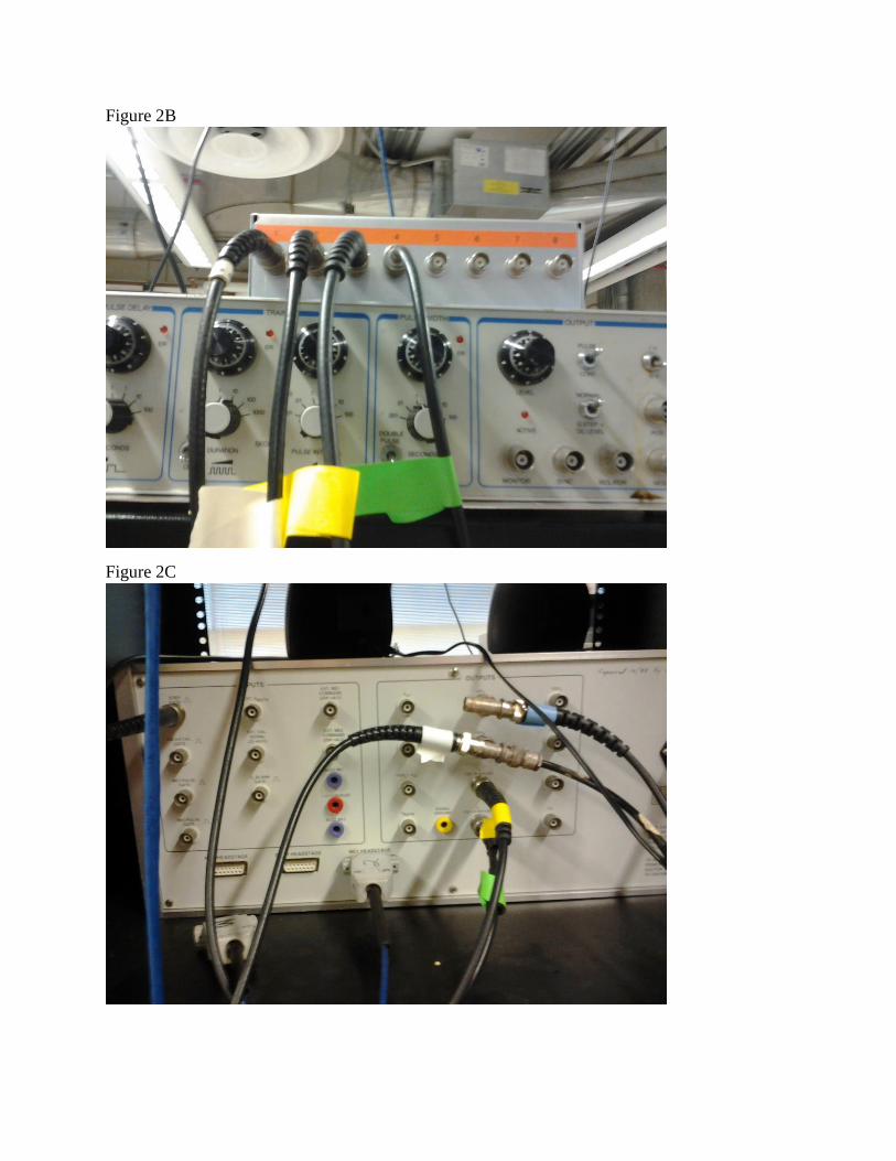
Figure 2B
Figure 2C
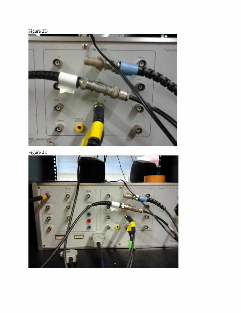
Figure 2D
Figure 2E
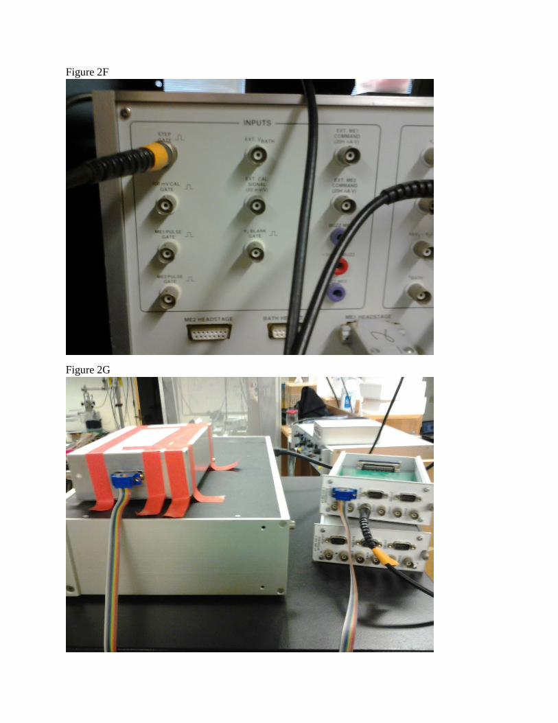
Figure 2F
Figure 2G
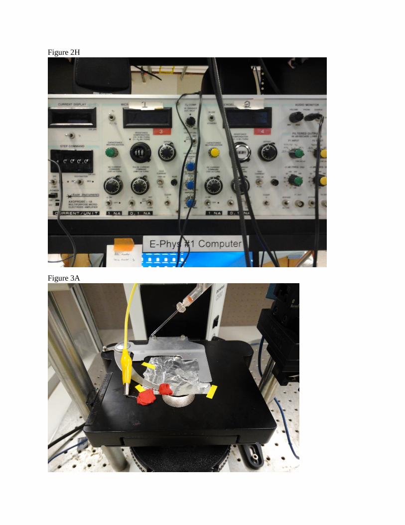
Figure 2H
Figure 3A
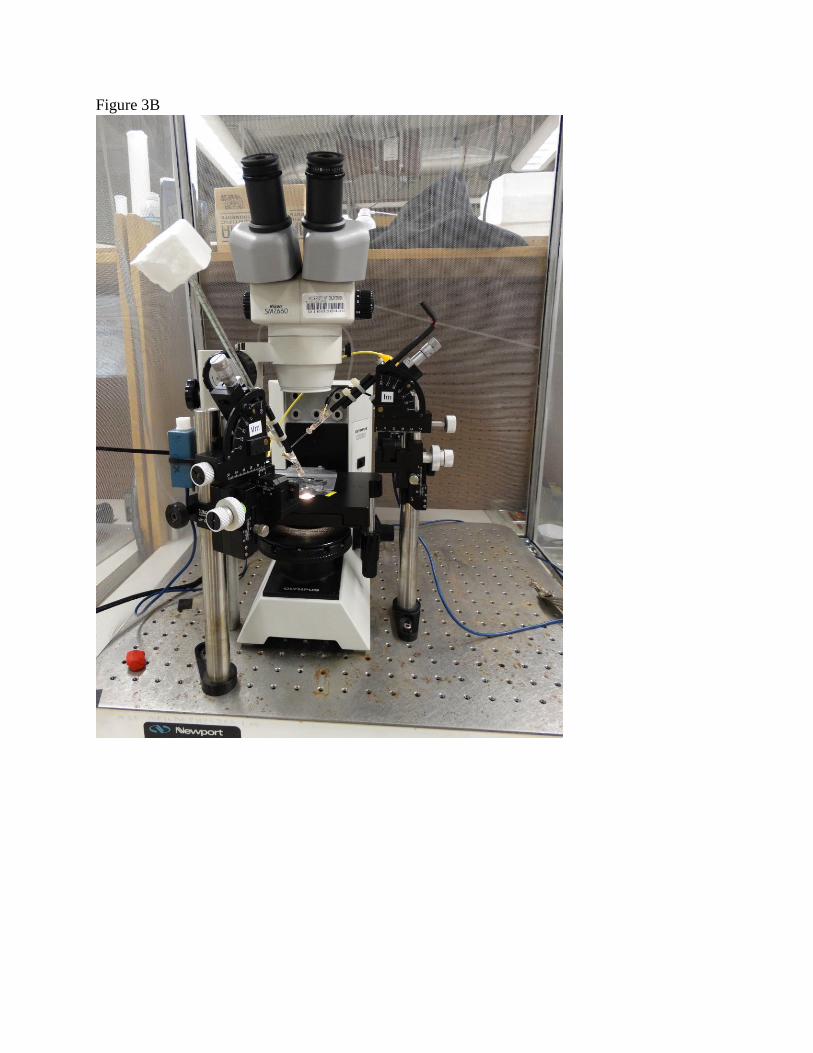
Figure 3B
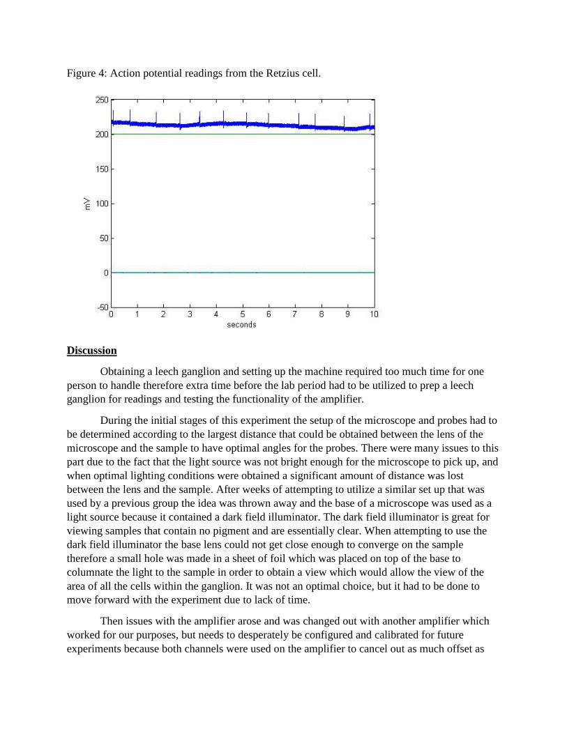
Figure 4: Action potential readings from the Retzius cell.
Discussion
Obtaining a leech ganglion and setting up the machine required too much time for one
person to handle therefore extra time before the lab period had to be utilized to prep a leech
ganglion for readings and testing the functionality of the amplifier.
During the initial stages of this experiment the setup of the microscope and probes had to
be determined according to the largest distance that could be obtained between the lens of the
microscope and the sample to have optimal angles for the probes. There were many issues to this
part due to the fact that the light source was not bright enough for the microscope to pick up, and
when optimal lighting conditions were obtained a significant amount of distance was lost
between the lens and the sample. After weeks of attempting to utilize a similar set up that was
used by a previous group the idea was thrown away and the base of a microscope was used as a
light source because it contained a dark field illuminator. The dark field illuminator is great for
viewing samples that contain no pigment and are essentially clear. When attempting to use the
dark field illuminator the base lens could not get close enough to converge on the sample
therefore a small hole was made in a sheet of foil which was placed on top of the base to
columnate the light to the sample in order to obtain a view which would allow the view of the
area of all the cells within the ganglion. It was not an optimal choice, but it had to be done to
move forward with the experiment due to lack of time.
Then issues with the amplifier arose and was changed out with another amplifier which
worked for our purposes, but needs to desperately be configured and calibrated for future
experiments because both channels were used on the amplifier to cancel out as much offset as
possible on the first channel and the remaining offset was fixed on the matlab program. Luckily
an oscilloscope was paired with some of the channels to obtain direct data to determine
grounding and noise issues yet there was a slight issue of drift that occurred and was not able to
be fixed due to the possibility that the drift was being caused by the amplifier.
Usually for this experiment a sound indicator is used to determine when a cell was
breached with the probe. But the frequency was way too high for comfort for the others in lab,
thus it was very difficult to obtain a reading without a strong indicator other than viewing the
oscilloscope while attempting to probe. This is also the reason why data for other categorized
cells was never obtained due to the difficulty in telling when a cell was probed or close to a cell.
When the data in figure 4 was obtained it was first compared to accepted data for the
Retzius cell to determine the efficiency of the noise reduction from grounding and the Faraday
cage. It closely resembled the accepted data yet the base line for the accepted data was a lot
thinner than the baseline obtained and the spikes were much larger.
Conclusion
In conclusion this experiment was very difficult to conduct single handedly with the
teaching assistants due to the time required for prepping the sample and the setup therefore it is
recommended that this experiment be done with partners. Secondly the amplifier needs to
desperately be calibrated for future use and to lessen the headaches of future students. It is highly
recommended that the microscope setup be redone to optimize the view because the view
obtained was very rudimentary, but worked for the purpose of testing the whole system; and
instead of using leeches as a test for the microscope’s view a scrapping of cheek cells should be
used during the first weeks while simultaneously learning the leech dissection. For future
experiments it would be optimal to practice probing smaller neural cells (this lab was done in
short time therefore practice was very minimal) and utilizing both channels of the amplifier to do
what this lab initially intended and monitor the interactions between cells.
References
1. http://www.biomedcentral.com/1471-2202/13/S1/F1/figure/F1
2. http://physics.ucsd.edu/neurophysics/courses/physics_173_273/leech_kernel.pdf
3.http://physics.ucsd.edu/neurophysics/courses/physics_173_273/Myomodulin_effects_on_P%2
0to_AP.pdf