mechanics of the panama canal slides. - … of the panama canal slides. 255 section of the bank must...
TRANSCRIPT
MECHANICS OF THE PANAMA CANAL SLIDES.
By GEORGE F. ~ECKER.
PREFATORY NOTE.
By GEORGE OTIS SMITH.
This geophysical study of the Panama Canal slides is now presented for the reasons set forth in the following letter of transmittal:
The DIRECTOR.
SIR:
I have the honor to transmit herewith a paper on the mechanics of the Panama Canal slides. It was prepared as a contribution to the report of the committee of the National Academy of Sciences on the Panama Canal slides, appointed at the instance of the President of the United States.
As some delay is anticipated in completing the full report, this chapter is now submitted for publication with the sanction of President C. R. Van Rise, chairman of the committee.
Very truly, yours, GEORGE F. BECKER.
Dr. Becker visited the Canal Zone in 1913 as a geologist of the United States Geological Survey and since that time has given the problem the benefit of his study. His appointment as a member of the committee of the National Academy of Sciences has made it appropriate for his conclusions, based upon his personal observations and already reported in part to the Canal Connnission, to be stated for the benefit of his associates and other American scientists and engineers.
OBSERVATIONS ON THE SLIDES.
Early in 1913, before water was admitted, I spent some weeks in examining the geology of the Culebra Cut, now officially known as the Gaillard Cut, with special reference to the origin of the landslides.1 These appear to me to be of two kinds--rnere superficial slips on joint planes or other slippery surfaces and deeperseated "breaks," as they are known by the
1Ihad.thegreat advantage of Mr. Donald MacDonald's companionship throughout these field studies.
engineers. It is only with the latter that this paper is concerned.
The breaks in their inception are marked on comparatively level banks by groups of cracks or narrow fissures nearly parallel to the cut, . and these almost immediately develop into series of step faults with small throws, many of them only a fraction of an inch in height, the hade where not vertical being invariably toward the canal so far as I could observe.2 :Many of the steps of these faults are . only a _yard or two in width. There seems little order in the time of formation of the cracks; in some breaks groups of small faults first appear rather close to the cut, those at a greater distance from it developing later. In others the earliest cracks are hundreds of feet from the canal and the intermediate ground splits up afterward. In all the breaks which I could examine the first small movements involved no perceptible gaping, or none of the same order of magnitude as the throws of the faults. At or about the same time as the cracks on the bank were formed nearly horizontal cracks also appeared in the cut near the bottom of the bank, but which of these were the earlier it seemed impossible to decide.
After a break has made a fair start the cracks more remote from the cut gape and show underlying curved surfaces which reach the general level of the top of the bank nearly at right angles or crop out almost vertically, and at the outcrop the vertical cross section of such a surface shows a very moderate radius of curvature. The surfaces of rupture are fairly smooth, many of them slickenslided a little
2 Mr. MacDonald records that ''some of the blocks sank a little in front and tilted up in the rear, so that they were a yard above the front part of the block behind." This behavior was unusual, and I saw no instances of it. Local inhomogeneities in the bank might perhaps bring about irregularities in surfaces of rupture which would account for excevtional throws of 2 or 3 feet. No other suggestion on this subject occurs to me.
253
254 SHORTER CONTRIBUTIONS TO GENERAL GEOLOGY, 1916.
below the outcrop, but not smooth enough to make accurate measurements of their radii of curvature practicable. As nearly as I could discover these radii measured between 100 and 200 feet. Where these underlying surfaces are exposed to a considerable extent it is apparent that the radii of curvature increase rapidly with increasing -depth, and some exposures from which disintegrated material had been removed appeared to prove that as the cut is approached the radius of curvature becomes very large indeed.
Movement of the slides perhaps never entirely ceases, but it varies greatly in velocity, from a fraction of an inch a day to many yards. After considerable motion has taken place the sheets of rock are broken up and the external surface of the slide becomes as rough as a choppy sea.
A certain amount of consolidation and of what might be called secondary cohesion sometimes occurs in a slowly moving slide of large dimensions after the material has been reduced to a chaotic condition. In such cases welldeveloped curved surfaces of rupture and step faults form, indistinguishable in general character from the initial disturbances in the solid bank. This surprising fact indicates that definite mechanical laws of wide applicability underlie the formation of slides. I was witness to these phenomena in the Cucaracha slide, and they have made their appearance in other and more recent breaks.
During the progress of a large slide upheaval of the bottom of the canal may take place from time to time, showing that deformation of the rocks extends to a certain depth below the deepest excavation; but this upheaval does not attend every spasm of activity in the slide, nor does the amount of material thrust up indicate that deformation extends more than a few yards beneath the bottom of the canal. A layer of rock say a hundred feet in width, buckled by nearly horizontal pressure, would show, even if it were only a couple of yards in thickness, mounds of rubble as much as 20 or 30 feet in height, or of the order of magnitude of the observed upthrusts.
LIMITING DEPTH OF DISTURBANCE.
To simplify the mechanical problem as much as possible, suppose the case of a level plain underlain to a great depth by an ideally ho-
mogeneous rock. At any depth in this rock the pressure will be hydrostatic and equal to the depth multiplied by the density. Suppose a narrow trench to b~ sunk vertically in this rock, the width being so small that caving of the sides can be prevented by mine timbering. Then, because of the one-sided relief of pressure there will be at the bottom of the cut a horizontal stress, directed from the wall into the cut, which is equal to the product of the depth ·and the density. This stress will tend to produce a horizontal shear and to drive the bottom of the wall into the cut. If the cut is sunk deep enough, so deep that the stress is equal to the resistance of the rock to simple , shearing stress at the elastic limit, this deformation will occur and the wall will bulge.
This seems a rather hasty statement, but in the last section of this paper the strains are considered in detail; it is there shown that the elastic limit for simple shear would be reached long before the limit for mere linear compression, and that of all elementary resistances that resistance which opposes stress such as is exerted by a pair of scissors is the weakest.
Let the limiting depth at which this one species of flow makes its appearance be denoted by y17 so that if p is the density the hydrostatic pressure is py17 which is also the value of the shearing stress.
CONDITIONS IN A WIDE CUT.
The hypothesis of a narrow timbered cut was employed in finding the limiting depth, y 1,
in order to avoid the complication of a caving bank. Let a wide cut be substituted, one a mile wide if the reader chooses, but let the bank be vertical. Then even before the depth y1 is attained any real rock wall would break down or cave. But imagine for a moment the rock replaced by a substance so tough that, though it would undergo permanent deformation at the same limit as the rock, it would hang on long enough to be studied. A ductile substance, such as wrought iron, would act in this way.
Consider a surface of uniform deformation nearly as deep as y1 and extending into the wall. This surface will surely not be horizontal, for such a strain would imply the expenditure of an infinite amount of energy.
Before caving oan take place in a homogeneous bank the material of the bank must be strained to its elastic limit. rfhe vertical cross
MECHANICS OF THE PANAMA CANAL SLIDES. 255
section of the bank must therefore include a line along which the strain is uniform. This line must reach the top of the bank somewhere, and it may be assumed that the line is curved, because that is a far more general hypothesis than that it is straight, besides being in harmony with observation.
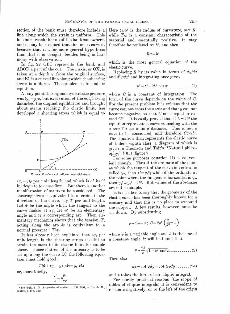
In fig. 22 OBO represents the bank and ABOD a part of the cut. The x axis, or OX, is taken at a depth y 1 from the original surface, and EO is a curved line along which the shearing stress is uniform. The problem is to find its equation.
At any point the original hydrostatic pressure was (y1 -y)p, but excavation of the cut, having disturbed the original equilibrium and brought about strain reaching the elastic limit, has developed a shearing stress which is equal to
y I I I I
~------r:~o.__--------T--
E
D --------------X
FIGURE 22.-Curve of uniform t an gential strain.
(y1 -y)p per unit length and which is of itself inadequate to cause flow. But there is another manifestation of stress to be considered. The shearing stress is equivalent to a tension in the direction of the curve, say T per unit length. Let if; be the angle which the tangent to the curve makes at xy; let oif; be an elementary angle and os a corresponding arc. Then elementary mechanics shows that the tension, T, acting .along the arc os is equivalent to a normal pressure 1 Toif;.
It has already been explained that py1 per unit length is the shearing stress needful to strain the mass to its elastic limit for simple shear. Hence if stress of this intensity is to be set up along the curve EO the following equation must hold good:
Toif;+ (y1 -y) pos=y1 pos
or, more briefly, T OS -=y-p oif;
1 See 'l'ait, P. G., Properties of matt er, p. 2&1, 1894; or Lamb, H., Statics, p. 276, 1912.
Here osjoif; is the radius of curvature) say R, while T j p is a constant characteristic of the material and essentially positive. It may therefore be replaced by b2
, and then
which is the most general equation of the elastic curve.
Replacing R by its value in terms of dyjdx and d2y/dx2 and integrating once gives
y 2 = 0- 2b2 COS if; ___________ (1)
where 0 is a constant of integration. The form of the curve depends on the value of 0. For the present pNblem it is evident that the curve can not cross the x axis and that y can not become negative, so that 0 must equal or exceed 2b2• It is easily proved that if 0= 2b2 the equation represents a curve coinciding with the x axis for an infinite distance. This is not a case to be considered, and therefore 0> 2b2
•
The equation then represents the elastic curve of Euler's eighth class, a diagram of which is given in Thomson and Tait's "Natural philosophy," § 611, figure 7.
For some purposes equation (1) is convenient enough. Thus if the ordinate of the point at which the tangent of the curve is vertical is called Yv, then O=yi; while if the ordinate at the point where the tangent is horizontal is y 0 ,
then y02 = Yv2 - 2b2• But values of the abscissae
are not so simple. It is needless to say that the geometry of the
elastic curve has been thoroughly known for a century and that this is no place to expound the subject. A few results, however, must be set down. By substituting
where cp is a variable angle and 7c is the sine of a constant angle, it will be found that
- 2b I Jc2 . z (2) Y - JC -y 1 - Sln cp- - - - - - - - - - -
Then also
dx =cot if;dy == cot 2cpdy _______ (2a)
and x takes the form of an elliptic integral. For purely practical reasons (the scope of
tables of elliptic integrals) it is convenient to reckon x negatively, or to the left of the origin

256 SHORTER CONTRIBUTIONS TO GENERAL GEOLOGY, 1916.
in figure 23. Then, in the conventional terminology of these integrals/
If, for example, the horizontal distance from the origin to the vertical tangent of the curve is required, if;= -n/2 and cp=7r/4, and the value of x can be computed from tables of elliptic integrals. Because of symmetry, positive values of x have the same absolute value as negative values.2
The element of area of the curve, ydx, rs independent of k:
ydx= 4b2 (sin2cp -~) dcp= b2 cos if;dif;
so that
Itt-ydx = b2 sin t/; _____________ ( 4)
a result which can be found directly from (1) and (2a).
The length of the curve counted from the horizontal point is given by
-%=k{K- F (k,cp)} ___________ (5)
and s/b is thus si1nply proportional to the first part of the value for - xjb.
It should be remarked that b2 is an absolute constant dependent· only on the density and tenacity of the rock, so that geometrically b is the unit in which lengths are computed and b2
the unit area. On the other hand, k varies from curve to curve of a family of curves, all of which share a common value of b, but as 7c
· is the sine of an angle it can not exceed unity.
_LIMITING VALUES OF k.
It has already been pointed out that if 0= 2b2 the elastic curve is a horizontal straight line coinciding with the x axis. The same equality implies that k is unity, and therefore; for the problem under discussion, k must always be the sine of an angle less than 1rj2. It
1 For the meaning of the symbols in equation (3), see for example Peirce's "Short table of integrals."
2 Equation (3) is substantially identical with that given by Lamb (Statics, p. 279), who, however, takes tha origin at a different point, making x and cp disappear toget:B.er, so that the y axis includes the maximum value of y. In (3) the origin is so transposed that x and ,p disappear together, so that, as required for the problem in hand, they axis passes through the minimum value of y, or the point for which cp=7r/2.
is equally evident that k can not vanish, for were it to do so the curve would intercept the vertical axis at an infinite distance. There are other reasons for supposing that k can not be very small, and these can be very briefly stated. In this discussion it has not been needful to consider any strains except those at the elastic limit, but the general theory of elastic strains shows that at the edge of a vertical cliff or bank there will be no strain at all, and for some distance from such an edge the strains will be exceedingly small. Hence strains reaching the elastic limit are not to be considered near this edge. It might be possible, but it would not be worth while, to determine how near to this edge the elastic limit· could be reached.
On the other hand, it is very important to consider how far back a curve of critical shear can reach, and this I believe to be a simple problem. From the manner in which the equation of the elastic curve was derived it is apparent that the pressure due to tension is a secondary phenomenon due to elastic strain. It is unthinkable that this part of the pressure should exceed the whole pressure requisite to produce flow. But when the curve crops out on the bank at 90° to tlre horizontal, the pressure due to tension at the outcrop exactly equals the critical tension, y1p. Hence for a given value of y1 the lowest possible curve is that which intersects the level bank at right angles. From this condition the maximum value of ~ can be determined.
EXAMPLES OF SLIDE CURVES.
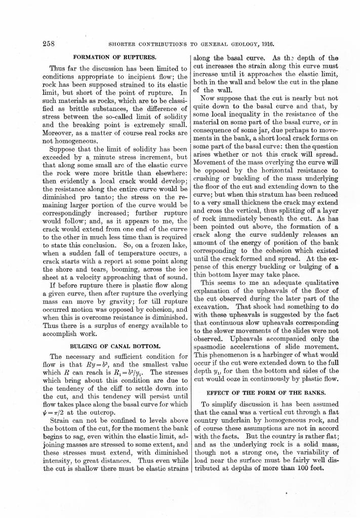
In order to illustrate conditions resembling, to a first approximation, those met with in the Culebra Cut, I have computed a few values of the more important elements of the curves, and these are tabul~ted below. It is easy to see that only relatively large values of k =sin a are of interest and I have begun with a = 7 5°. Taking x1 as the abscissa of the vertical tangent, it is found from equation (3), while if Yo is the value of the ordinate for x = o, y0/b = 2 cot a. Then y1
2/b2 =y02/b2 +2. The fundamental rela
tion y/b =b/R makes it easy to find the radii of curvature answering to X1Y1 and XoYo· For the purpose of the diagram it is not requisite to compute other points; after describing an arc at the axis of symmetry with ~/band a second

MECHANICS OF THE PANAMA CANAL SLIDES. 257
arc at x1y1 with R 1/b, the two can be connected without serious error by the help of a curved ruler.
Points on the elastic curve.
k X1/b Yofb ytfb Rofb Rtfb
--- ---
sin 75°---- _. 1. 3411 0.5358 1. 512 1. 866 0.661 sin 80° ______ 1.7094 . 3526 1.458 2.836 0 686 sin 85° - -- - - - 2.3728 .1750 1.425 5. 714 . 702 sin 89° - - ---- 3.9690 . 0350 1. 415 28.570 . 707 sin 90° ______
00 0 1. 414 00 . 707
To estimate an appropriate value for b it is requisite to adopt some value for the resistance of the rock either to shearing stress or to crushing. The ultimate resistance to crushing of such materials as soft-burned brick, inferior concrete, and the poorest sandstones is somewhat less than 3,000 pounds per square inch.
X i I I I
r:soo'r' -------.r--r---.-----..-~-----
·zoo
FIGURE 23.-Elastic curve for a=75°, 80°, 85°, 89°.
The Cucaracha formation is probably of similar strength, and I will assume its resistance to be 2, 760 pounds. In the concluding section of thi~paper reasons are giv~n for supposing that 6 ..j2 times the resistance to shear is about equal to the resistance to crushing; and this implies that for the Cucaracha the resistance to shear is 325 pounds per square inch. This is the weight of a column of rock of a density 2.5 times that of water and 300 feet high.
If the curve for which a= 89° is selected and y1 is taken as 300 feet,
2
b2 = 2 (l+~1 cot2a) 44,972; b=212
By multiplying all the lengths given in the table by 212 a consistent set of values is obtained.
In the diagram (fig. 23) the height of the bank above the x axis is taken as 300 feet and the curve for a=89° cuts it perpendicularly at a distance of 841 feet from the y axis. The
curves for smaller valu~s of a give larger _values for y1 and therefore cut the 300-foot level at acute angles.
According to the theory here set forth, a limit is set to the vertical height of a cliff or of any rock. Results obtained by the United States Geological Survey indicate that granites show resistances up to 34,000 pounds per square inch, which would correspond to a cliff 3,700 feet high. The brow of El Capitan, in the Yosemite Valley, stands 3,100 feet above the valley, but the top of the dome, some 2,000 feet bac.k from the brow, is about 500 feet higher.
HYDROSTATIC ANALOGY.
If two rectangular blocks of very clean glass are placed in a dish, parallel to one another, and if water is added until the faces of the blocks nearest together are wet to the top in consequence of capillarity, then the vertical cross section of the water surface between the blocks is the elastic curve represented by equations (2) and (3); the height of the blocks above the general water level is given by y1b, and the amount of water raised above this level by capillarity or surface tension is b2 per unit length for each wall of the channel between the blocks. If the surface tension is T and the density is p then Tfp= b2
•
This system is in ~table equilibrium, the surface of the water is minimal for the boundary conditions, and, as the equilibrium is stable, the gravitational potential is a minimum. The whole system may be supposed solidified without disturbance of equilibrium. One-half of this model, to the right or the left of the point at which the capillary curve is lowest, represents the mass beneath a slide on the Culebra Cut. The whole model represents the slide surfaces as they would be were the cut extremely narrow, provided that the material sliding in were removed as fast as it came until the slides ''died.''
This very perfect analogy and the theory of this paper seem to me to show that the profile of the bed or bottom of a straight watercourse or river, flowing through a homogeneous stretch of country, must tend to approach the elastic curve, and that this profile is also most suitable for a canal.
258 SHORTER CONTRIBUTIONS TO GENERAL GEOLOGY, 1916.
FORMATION OF RUPTURES.
Thus far the discussion has been limited to conditions appropriate to incipient flow; the rock has been supposed strained to its elastic limit, but short of the point of rupture. In such materials as rocks, which are to be classified as brittle substances, the difference of stress between the so-called limit of solidity and the breaking point is . extremely small. Moreover, as a matter of course real rocks are not homogeneous.
Suppose that the limit of solidity has been exceeded by a. minute stress increment, but that along some small arc of the elastic curve the rock were more brittle than elsewhere: then evidently a local crack would develop; the resistance along the entire curve would be diminished pro tanto; the stress on the remaining larger portion of the curve would be correspondingly increased; further rupture would follow; and, as it appears to me, the crack would extend from one end of the curve to the other in much less time than is required to state this conclusion. So, on a frozen lake, when a sudden fall of temperature occurs, a crack starts with a report at some point along the shore and tears, booming, across the ice sheet at a velocity approaching that of sound.
If before rupture there is plastic flow along a given curve, then after rupture the overlying mass can move by gravity; for till rupture occurred motion was opposed by cohesion, and when this is overcome resistance is diminished. Thus there is a surplus of energy available to accomplish work.
BULGING OF CANAL BOTTOM.
The necessary and sufficient condition for flow is that Ry = b2 , and the smallest value which R can reach is R1 = b2/y1• The stresses which bring about this condition are due to the tendency of the cliff to settle down into the cut, and this tendency will persist until flow takes place along the basal curve for which 1/; = 1r/2 at the outcrop.
Strain can not be confined to levels above the bottom of the cut, for the moment the bank begins to sag, even within the elastic limit, adjoining masses are stressed to some extent, and these stresses must extend, with diminished intensity, to great distances. Thus even while the cut is shallow there must be elastic strains
along the basal curve. As thJ depth of the cut increases the strain along this curve must increase until it approaches the elastic limit, both in the wall and below the cut in the plane of the wall.
Now suppose that the cut is nearly but not quite down to the basal curve and that, by some local inequality in the resistance of the material on some part of the basal curve, or in consequence of some jar, due perhaps to movements in the bank, a short local crack forms on some part of the basal curve: then the question arises whether or not this crack will spread. Movement of themass overlying the curve will be opposed by the horizon tal resistance to crushing or buckling of the mass underlying the floor of the cut and extending down to the curve; but when this stratum has been reduced to a very small thickness the crack may extend and cross the vertical, thus splitting off a layer of rock immediately beneath the cut. As has been pointed out above, the formation of a crack along the curve suddenly releases an amount of the energy of position of the bank corresponding to the cohesion which existed until the crack formed and spread. At the expense of this energy buckling or bulging of a thin bottom layer may take place.
This seems to me an adequate qualitative explanation of the upheavals of the floor of the cut observed during the later part of the excavation. That shockhad something to do with these upheavals is suggested by the fact that continuous slow upheavals corresponding to the slower movements of the slides were not
·observed. Upheavals accompanied on(y the spasmodic accelerations of slide movement. This phenomenon is a harbinger of what would occur if the cut were extended down to the full depth Yu for then the bottom and sides of the cut would ooze in, continuously by plastic flow.
EFFECT OF THE FORM OF THE BANKS.
To simplify discussion it has been assumed that the canal was a vertical cut through a flat country underlain by homogeneous rock, and of course these assumptions are · not in accord with the facts. But the country is rather flat; and as the .underlying rock is a solid mass, though not a strong one, the variability of load near the surface must be fairly well distributed at depths of more than 100 feet.
MECHANICS OF THE PANAMA CANAL SLIDES. 259
Until slides began to give trouble the banks of the cut were very steep-quite too steep, in fact, as everyone would now concede. It is well to consider what would have been the effect of giving the excavation lower slopes.
The ordinary theory of earth pressures on retaining walls is based on the existence of an angle of rest in a pile of discrete particles. It appears to me to be totally inapplicable to conditions in the Cucaracha formation, for the mere existence of breaks demonstrates that the mass possesses continuity. The rocks of the Culebra Cut behave very much as a mass of agar-agar jelly might do if a rectangular mold of this substance, a foot or so in depth, were turned out on a horizontal table. If the jelly were of the right degree of stiffness, the edges of the mass ·would first sag, and then breaks would make their appearance; but nothing resembling a constant angle of rest would be developed. To work out a complete theory of the relief of pressure in such a jelly, or in the Cucaracha formation, due to an inclination of the walls, would probably be very difficult. Nevertheless, very simple considerations show that sloping the walls is an effectual method of reducing the pressure.
If the Culebra Cut were replaced by an exceedingly strong wall, the pressure against the wall would be hydrostatic. For a small change of depth the increment of pressure would be p(y1 -y)d(y1 -y) , and the whole horizontal pressure from the surface to depth y1 - Yo
would be i (y1 - Yo) 2•
Now, imagine a plane inclined to the horizon at 45° and passing through the point x=o, y=y0 • This plane would cut off a triangular slab, say of unit thickness and of mass w =! p(y1 - Yo)2
•
The amount of frictional resistance depends primarily upon normal pressure, so that if F is the frictional resistance and N the normal pressure
F N=J.t=tan {}
where J.t is the coefficient of sliding friction and {}the angle of friction. Now, F can not exceed the normal pressure N, which excites it, so that J.t can not exceed unity and {} can not exceed 45 °. Hence friction can not prevent
movement on a slope of 45°. Thus if the triangular mass of rock (or of jelly) were actually separated from the remainder of the mass, friction would not prevent it slipping down the steep slope. The tangential pressure which the mass w would exert on the 45 ° plane would be wf-J2, and this would be resolved into a vertical pressure and a horizon tal pressure each equal to w/2.
Thus of the whole hydrostatic horizontal thrust exerted against the vertical wall, just one-half is exerted by the triangular slab. Hence also sloping the bank of a cut at 45° would diminish the horizontal thrust to onehalf of its maximum value.
It is not difficult to perceive by the further application of elementary statics that the thrust would be still more diminished by making the slope smaller than 45°.
The precaution of giving the banks a low slope might have prevented the occurrence of slides, but as a remedial measure, after breaks have developed to a considerable extent, it seems to me of little avail. After the basal curve has developed into a crack, the material overlying it is either in motion or in unstable equilibrium; and sooner or later all, or nearly all of it, will reach the bottom. Slides of origin similar to those of the Culebra Cut are by no means confined to the Canal Zone. In my opinion banks of cuts should be watched with extreme care, and the moment any cracks make their appearance all other work should be suspended until a safe slope has been established. Breaks should be prevented, because they can not be cured.
NOTE ON FINITE STRAINS.
Plastic flow is continuous deformation without change of density. It takes place at the so-called limit of solidity. During flow, therefore, a solid must be treated as compressed to a constant extent, and as the elasticity of volume is perfect, when stress is relieved the original volume is restored. In nearly all cases a solid mass undergoing flow is to be treated as incompressible.
This limit of solidity depends on the type of strain to which the mass is subjected and to some extent on viscosity. It would also depend on heterotropy, but this paper deals only with isotropic matter.

260 SHORTER CONTRIBUTIONS TO GENERAL GEOLOGY, 1916.
In any strain ellipsoid there are two symmetrically oriented sets of planes of maximum tangential strain or maximum slide. If the strain is a rotational one (so that the groups of material particles through which the ellipsoidal axes pass vary with the progress of the strain), then there is a difference in behavior of the mass on these two sets of planes. Along that set of geometrical planes which ro~ates more rapidly through the mass, or on which the material particles change more quickly, greater resistance is offered to flow or rupture than on the other set, because the resistance to be overcome is rigidity plus viscosity and because viscosity offers great resistance to a sudden stress but very small resistance to a stress slowly applied.
In one strain, called simple shear, shearing motion, slide, or scission by various writers, there is one set of these planes which is :fixed
their product is constant, and if all three diameters pass through the same material particles at all stages of the strain, then this strain is a shear, though not a siJ:I?.ple shear but yet far simpler than a simple shear. Both ~trains are illustrated in figure 24.
A pure shear may be conceived as the result-1 ant of two scissions whose rotations are equal and opposite, a fact of which use may be made in the present discussion.
If a cube of homogeneous isotropic matter is subjected to uniformly distributed pressure ori two opposite faces, or if the cube rests on al
I
rigid plane and carries a normal load or initial stress, P, then, no matter whether the load and the strain produced are infinitesimal or finite, just one-third of the load is employed in producing cubical compression, the remaining two-thirds being employed in producing two pure shears at right angles to each other.
r·········--~~~:.~~~-~-- - ···-- - ·····: I I
' ' ,:
_i_··------·----··-····------- ----------- --·--j FIGURE 24.-Diagram illustrating simple shear and shear, each of ratio 5/4. The broken lines show
directions of maximum. tangential stram.
relatively to the material, while the other set of planes of maximum tangential strain changes its position relatively to the material particles more rapidly than in any other strain.
In scission, therefore, flow will be more easily produced on the fixed set of planes than in a strain of any other type; but on the other set of planes flow will be less easily produced in scission than in a strain of any other type. Scission is due to a couple acting against aresistance. It is the only strain produced in a rod of circular cross section when the rod is twisted about its axis.
Irrotational or pure shear, usually denoted simply as shear, is the simplest conceivable deformation. If a sphere is so distorted that one diameter retains its length unaltered while two other orthogonal diameters, in a plane perpendicular to the first, are so changed that
If the strain at the elastic limit is small and if P just exceeds the initial stress needful to produce this strain, the conditions for flow are fulfilled. But to produce yielding relative motion must take place parallel to four planes all of which are at or very close to inclinations of 45 ° to the direction of the load. Suppose that there were only four planes of relative moti_on, each passing through two opposite edges of the cube; then if a face of the cube is assumed as the unit area, the area of each of the planes of relative motion will be {2, and to produce any yielding by shear the total area of relative motion must be at least 4{2 = 5.657.
Now on each of these four surfaces the relative motion may be conceived as due to a scission, the four rotations of the scissions annulling one another by pairs. But if the cube were cut or permanently deformed by scission along a

MECHANICS OF THE PANAMA CANAL SLIDES. 261
plane parallel to any face the area of deformation would be only unity instead of 5.657.
Call the load or initial stress, P, when just sufficient to induce flow by pure shears K, and let Ks be the tangential stress needful to induce incipient scission. Then it follows from the reasoning stated above that
~- K i K=4-v2Ks, or Ks= 8.485
so that if K is known a rational estimate of Ks can be made.
Experimental data as to the relative values of K and Ks for stone, concrete, or brick are not to be had, so far as I know; but for these substances the limit of elastic strain and the breaking point lie very close together. According to Bauschinger the ultimate resistance to shearing of stone is a thirteenth of the resistance to crushing, and this substantially coincides with Von Bach's result for granite. Thus experiment confirms the conclusion that relatively brittle substances will yield to shearing stresses very much less in tense than would be needed to produce flow by irrotational strains.
As flow is thus dependent on the type of strain, it follows that flow on one set of planes
of maximum tangential strain may be accompanied by no sensible plastic deformation on the opposite set or may there even be attended by rupture.
SUMMARY.
After describing the essential features of the breaks on the Culebra Cut the author points out that there is a limit to the depth of a vertical cut in an homogeneous isotropic mass, the upper surface of which is plane. This limit is that at which the pressure is sufficient to produce simple shear in the mass, and in a concluding note reasons are given for believing that 6-./2 multiplied by the resistance to such shear is about equal to the ultimate strength under linear compression. The depth at which one-sided relief of pressure will produce simple shear is called y1•
It is shown that in such a bank the profile of a surface along which the mass is strained to the elastic limit must be a form of the elastic curve, the directrix of which lies at a depth Yt·
The lowest or basal slide curve is one which intersects the horizontal bank at right angles. Examples are worked out for this and other cases.
A complete analogy exists between the form of these curves and those whieh the surface of water assumes when it rises by capillarity between verti al, parallel glass plates.
In view of these results the auth r discusses to some extent the formation of ruptures, t bulging of the canal bottom, and the effect upon pres ure of the form of the banks. A note on finite strains is laced at the end of the paper in order to facilitate skippi g.