mechanical principles of wheelchair design - mitweb.mit.edu/sp.784/www/documents/wheelchair...
TRANSCRIPT

Fperson
CG
F1
F2F3
Mechanical Principles Mechanical Principles Mechanical Principles Mechanical Principles
of Wheelchair Designof Wheelchair Designof Wheelchair Designof Wheelchair Design
Amos WinterAmos WinterAmos WinterAmos WinterGraduate Student, Department of Mechanical EngineeringGraduate Student, Department of Mechanical EngineeringGraduate Student, Department of Mechanical EngineeringGraduate Student, Department of Mechanical Engineering
Massachusetts Institute of TechnologyMassachusetts Institute of TechnologyMassachusetts Institute of TechnologyMassachusetts Institute of Technology
Ralf HotchkissRalf HotchkissRalf HotchkissRalf HotchkissChief Engineer Chief Engineer Chief Engineer Chief Engineer
Whirlwind Wheelchair InternationalWhirlwind Wheelchair InternationalWhirlwind Wheelchair InternationalWhirlwind Wheelchair International
This manual is free to anyone. Please photocopy and distribute.
Where useful
This manual is free to anyone. Please photocopy and distribute. 1
Description
Forces
A force is the amount one object tries to push or
pull another object. The earth exerts a force on
every object, pulling it towards the ground. This
is known as the force due to gravity. When you
measure the weight of a person, you are
measuring the force of gravity pulling on him.
When an object is stationary all the forces acting
on it are balanced. When the forces are not
balanced, the object will move. Forces are
measured in Newtons or pounds. To convert
kilograms to Newtons, multiply the number of
kilograms by 9.81. One kilogram is equal to 2.2
lbs.
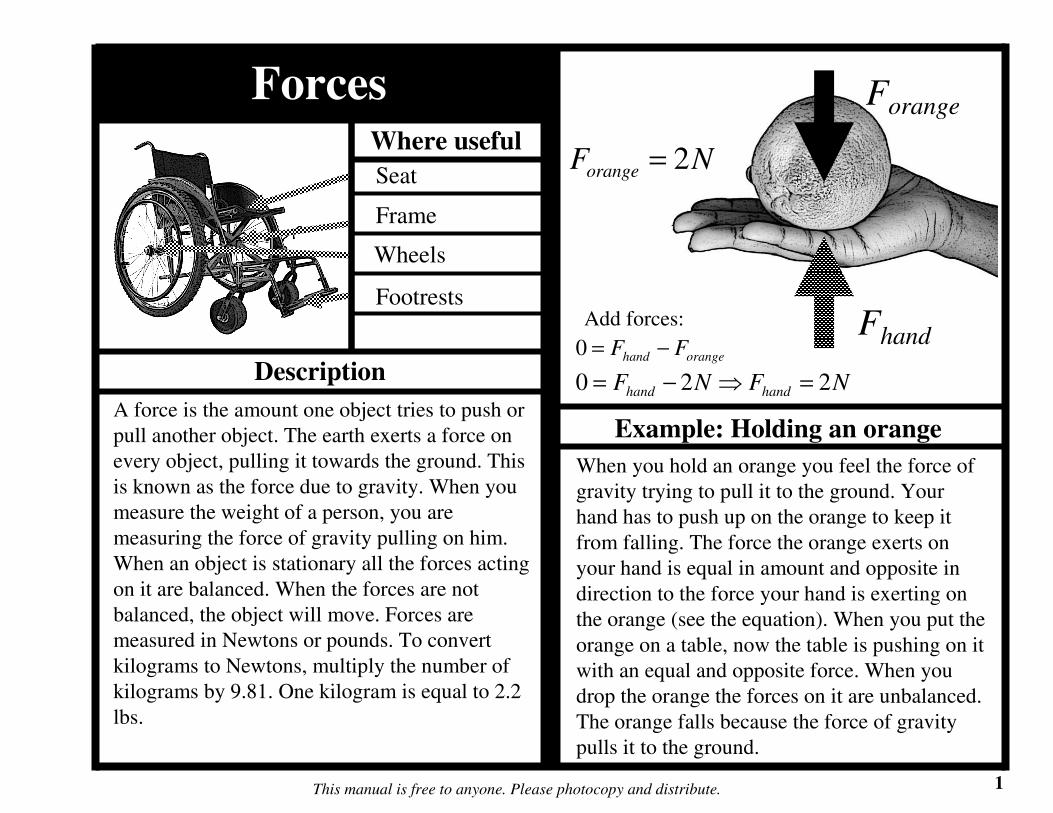
When you hold an orange you feel the force of
gravity trying to pull it to the ground. Your
hand has to push up on the orange to keep it
from falling. The force the orange exerts on
your hand is equal in amount and opposite in
direction to the force your hand is exerting on
the orange (see the equation). When you put the
orange on a table, now the table is pushing on it
with an equal and opposite force. When you
drop the orange the forces on it are unbalanced.
The orange falls because the force of gravity
pulls it to the ground.
Seat
Frame
Footrests
Example: Holding an orange
Wheels
Forange
Fhandorangehand FF −=0
NFNF handhand 220 =⇒−=
NForange 2=
Add forces:

Where useful
This manual is free to anyone. Please photocopy and distribute. 2
Description
Center of gravity
The center of gravity (CG) of an object is the
point where it can be balanced. If you wanted to
think of gravity pulling on an object at a single
point, the CG is that location. Understanding CG
location is important in wheelchair design. You
can approximate the force a person exerts on a
wheelchair as his total weight applied at the CG
of his body, which is a point around his hips.
Seat
Frame
Footrests
Example: Find the CG of a wrench
Wheels
The CG of the wrench is the point where the
wrench can be balanced. More mass is
concentrated at the head, which makes the CG
closer to the head and not at the center of the
handle.
Fwrench
Ffinger
NFFF fingerwrenchfinger 100 =⇒−=
CG
Lhandle Lhead
headhandle LL >
NFwrench 10=
Add forces:

Where useful
This manual is free to anyone. Please photocopy and distribute. 3
Description
Free body diagram
A free body diagram (FBD) is a visual
representation of the forces acting on an object.
You have already seen FBDs in the previous
examples. As in the case of stationary objects,
like the orange and wrench example, there are
forces acting on them to balance the force of
gravity pulling them to the ground.
Seat
Frame
Footrests
Example: Sitting in a wheelchair
Wheels
The figure shows the FBD of a person in a
wheelchair. If you know the weight of the
person you know the force her body exerts on
the wheelchair. Because the wheelchair is not
moving the forces the ground exerts on the
wheels and casters must add up to be equal and
opposite to the force from the person’s weight
(note the “Add forces” equation is for 2 wheels
and 2 casters). In the next sections you will
learn how to calculate the forces exerted by the
ground on the wheels and casters.
Fperson
Fwheel
CG
Fcaster
NFperson 500=
personwheelcaster FFF −+= 220
?=wheelF
?=casterF
Add forces:
Where useful
This manual is free to anyone. Please photocopy and distribute. 4
Description
Moments
A moment is like a force, but instead of trying to
push an object it tries to twist it. A moment is a
force applied to a lever arm. When you tighten a
bolt, you apply a moment to the bolt with a
wrench. You produce the force with your body
and the lever arm is the handle of the wrench.
The moment is calculated by multiplying the
force times the perpendicular (at a 90o angle)
distance from the pivot point. In every FBD, if
the object is stationary, both the forces and
moments need to add up to zero.
Frame
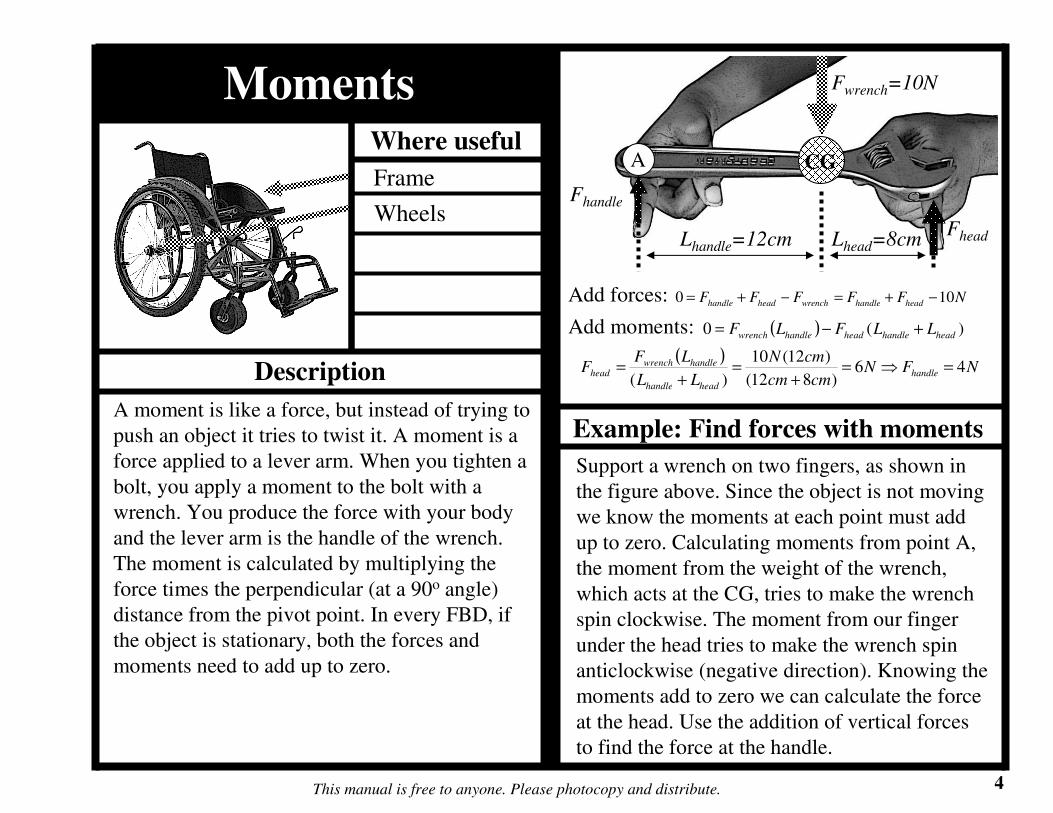
Example: Find forces with moments
Wheels
Support a wrench on two fingers, as shown in
the figure above. Since the object is not moving
we know the moments at each point must add
up to zero. Calculating moments from point A,
the moment from the weight of the wrench,
which acts at the CG, tries to make the wrench
spin clockwise. The moment from our finger
under the head tries to make the wrench spin
anticlockwise (negative direction). Knowing the
moments add to zero we can calculate the force
at the head. Use the addition of vertical forces
to find the force at the handle.
Fwrench=10N
Fhandle
Lhandle=12cm Lhead=8cm
CG
Fhead
( ) )(0 headhandleheadhandlewrench LLFLF +−=
NFFFFF headhandlewrenchheadhandle 100 −+=−+=
A
Add forces:
Add moments:
( )NFN
cmcm
cmN
LL
LFF handle
headhandle
handlewrenchhead 46
)812(
)12(10
)(=⇒=
+=
+=

5This manual is free to anyone. Please photocopy and distribute.
Example: Forces on a wheelchair Example: Wheelchair tipping angle
A wheelchair will tip over when the forces and
moments acting on the chair become
unbalanced. When the wheelchair tips to a point
where the CG of the user is vertically aligned
with the point where the wheel contacts the
ground, the chair is unstable. The angle the
wheelchair makes with the ground at this point
is called the tipping angle (θtip), as shown in the
figure above. If the wheelchair tips further it
will fall over because there is no moment to
counteract the moment generated by the CG.
Find the forces acting on the wheels of the
wheelchair in the above figure. If you know the
weight of the person in the chair, the location of
her CG, and the distance between the wheels,
you can calculate the forces on the wheels by
using moments. The calculations in the
example above add the moments about the front
caster.
Fperson
FwheelFcaster
CG
Lcaster
Lwheel
( ) )(20 wheelcasterwheelcasterperson LLFLF +−=
personwheelscasters FFF −+= 220
Add forces:
Add moments:
( )
)( wheelcaster
casterperson
wheelLL
LFF
+=
NFF wheelscasters 500220 −+=
( )N
cmcm
cmNFwheel 200
)2.106.40(
6.40500=
+=
NFcaster 50=⇒
Fperson
Fwheel-ground
CG
θtiphtip
B
A
Tipping angle:
=⇒=B
A
B
Atiptip arctantan θθ
Can also calculate θtip from
height wheels lift off ground
=
A
htip
tip2
arcsinθ
Tipping angle and height for
different chairs geometries:
htipθtipA/B
28cm27o0.5
18cm21o0.4
11cm17o0.3

Where useful
This manual is free to anyone. Please photocopy and distribute. 6
Description
Internal forces
Forces and moments also act on the inside of an
object. We can use the same methods as in the
previous examples to find internal forces and
moments. If an object is stationary, you know
that all the forces and moments have to balance
each other. There are some different terms used
to describe what occurs inside an object: Forces
that try to stretch or compress an object are
called tensile (stretch) and compressive
(compress) forces. Forces trying to tear the
object are called shear forces. Moments are still
called moments on the inside of the object.
Frame
Example: Moments inside a wrench
Wheels
The moment a wrench applies to a nut is the
force multiplied by the length of the handle.
There is a moment at the head but no moment
at the end of the handle. Now imagine taking a
cut of the wench and drawing a FBD of both
pieces, which are stationary. The forces and
moments that act on the surface where the cut
was made on one piece are equal and opposite
to those on the cut surface of the other piece.
Imagine cuts at different places along the
wrench and notice the internal moment
decreases from the head to the handle.
Fhand
Mnut
LnutF
L/2
Cut
Mcut
Fhand
cutF L/2
Add forces:
Add moments:
handcutnut FFF ==
==
2),(
LFMLFM handcuthandnut

7This manual is free to anyone. Please photocopy and distribute.
Example: Internal moments and forces in a wheelchair axle
The forces and moments acting on the rear axle of a wheelchair can be calculated the same way as for
the wrench in the previous example. The maximum moment occurs where the axel is welded to the
frame. Think about what might cause moments on the axle. There are vertical forces exerted on the
wheel from the ground, but there also may be horizontal forces that act on the wheel when the chair
tips over. The total moment in the axle is difficult to calculate and requires using trigonometry. If you
are comfortable with trigonometry determine the moments in the axle when the chair is at the tipping
angle. As an estimation, calculate the moments caused from the full weight of a person pushing on
one rear wheel, both vertically and horizontally. As you will see in the next sections, the moment in
the axle will determine if the metal is strong enough. See the figure for the axle-moment calculation.
Fperson
Fperson=500NFperson
R
L
Faxle-vert
Faxle-horiz
R=0.305m
L=0.076m
( ) Axlepersonperson MRFLF +−= )(0
NFFF horizaxlehorizaxleperson 5000 =⇒−= −−
Add forces:
Add moments:
( )LRFM personaxle −=
NFFF vertaxlevertaxleperson 5000 =⇒−= −−
Maxle
( )mmNM axle 076.0305.0500 −=
mNM axle ⋅= 5.114

Where useful
This manual is free to anyone. Please photocopy and distribute. 8
Description
Area, volume, mass
In engineering you often need to calculate the
area or volume of a part. Area is important when
calculating the stress (see next section) and
volume is important when calculating the
weight. You can calculate the weight of an
object if you know its volume and density.
Density is a material property that tells how
much mass there is for a given volume. For
example, the density of water is 1 gram per each
cubic centimeter (written as 1g/cm3) and the
density of steel is 7.8g/cm3. Steel is heavier than
water, thus it sinks. If you want to know the
mass of a steel part, you would multiply the
density of the steel by the volume of the part.
For example, if your steel part had the
dimensions of 10cm by 10cm by 20cm, the
volume would be 10cm X 10cm X 20cm =
2000cm3. The mass would then be 7.8g/cm3 X
2000cm3 = 15600g (notice the units of cm3
cancelled out). 15600g is the same as 156kg.
Seat
Frame
Footrests
Example: Calculating mass of a part
Wheels
h
b
L
bhAArea ==
ALVVolume ==
hb
L
2
bhA =
ALV =
d L
4
2d
Aπ
=
di
do
( )22
4io ddA −=
π
ALV = ALV =
L
ρ(kg/m3)Material
13Plastic
(PVC)
12Rubber
(Butyl)
27Alum.
78.7Steel
(mild)
Density = ρ

9This manual is free to anyone. Please photocopy and distribute.
Example: Mass of one side of wheelchair frame
You can estimate the total weight of a frame by adding up the weight of all the tubing in the frame. If
you know the inner diameter, outer diameter, and length of each tube you can calculate the volume. If
you know the density of the tubing material, you can calculate the total mass. See the above example
for calculating the mass of a frame.
L1
L2L3
L4
L5
Ri
Ro( ) ( ) 22222 02.176.095.0 cmRRA io =−=−= ππ
Find the area of the frame tubing:
L1=76cm
L2=51cm
L3=76cm
L4=81cm
L5=13cm
Ro=76cm
Ri=76cm
ρsteel= 7.8g/cm3
Find the total length of frame tubing:
54321 LLLLLLtotal ++++=
32 30329702.1 cmcmcmLAV total =⋅=⋅=
cmL
cmcmcmcmcmL
total
total
297
1381765176
=
++++=
kggcmcm
gVm steel 36.22363303
8.7 3
3==⋅== ρ
Find the volume of steel:
Find the mass of the frame:
Where useful
This manual is free to anyone. Please photocopy and distribute. 10
Description
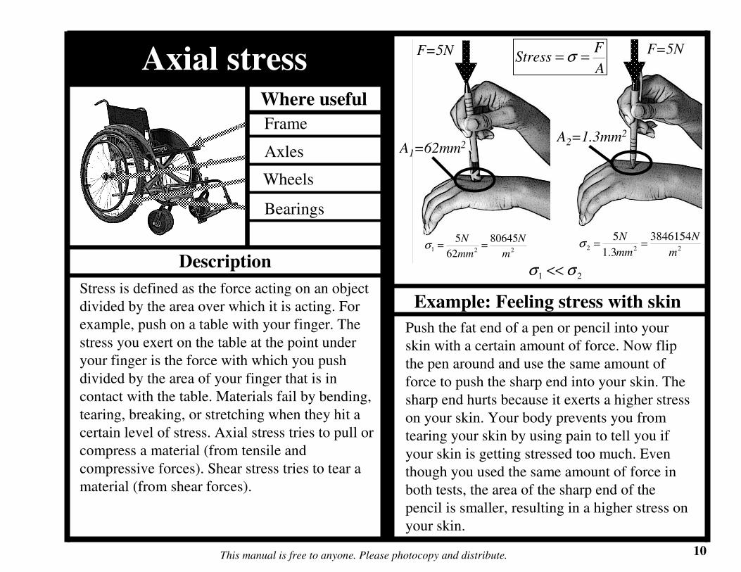
Axial stress
Stress is defined as the force acting on an object
divided by the area over which it is acting. For
example, push on a table with your finger. The
stress you exert on the table at the point under
your finger is the force with which you push
divided by the area of your finger that is in
contact with the table. Materials fail by bending,
tearing, breaking, or stretching when they hit a
certain level of stress. Axial stress tries to pull or
compress a material (from tensile and
compressive forces). Shear stress tries to tear a
material (from shear forces).
Push the fat end of a pen or pencil into your
skin with a certain amount of force. Now flip
the pen around and use the same amount of
force to push the sharp end into your skin. The
sharp end hurts because it exerts a higher stress
on your skin. Your body prevents you from
tearing your skin by using pain to tell you if
your skin is getting stressed too much. Even
though you used the same amount of force in
both tests, the area of the sharp end of the
pencil is smaller, resulting in a higher stress on
your skin.
Frame
Axles
Bearings
Example: Feeling stress with skin
Wheels
A
FStress == σ
221
80645
62
5
m
N
mm
N==σ
F=5N F=5N
A1=62mm2A2=1.3mm2
222
3846154
3.1
5
m
N
mm
N==σ
21 σσ <<

Where useful
This manual is free to anyone. Please photocopy and distribute. 11
Description
The level of stress when a metal first starts to
deform permanently under tensile or
compressive stresses is called the yield
strength. If more stress is applied to a metal
past the yield strength eventually the material
will break when it hits the ultimate strength.
Shear stresses can also permanently deform a
metal, and will be discussed in the next section.
When engineering a wheelchair you always
want to use a saftey factor (SF), meaning you
want to prevent the stresses from coming within
a certain factor of the yield strength. In most
cases a SF of 2 is enough but other cases
require much higher SFs, up to 10 or 20.
Take a piece of sheet metal and put it on a piece
of wood. Now take an indenter and hit it lightly
with a hammer. No dent is left because the
material was not stressed enough to
permanently deform. Now hit the material
harder and harder until you first start to make a
dent, which corresponds to the yield strength.
Hit harder so you make bigger dents and
eventually tear the metal, which corresponds to
the ultimate strength. As shown in the equation
above, the stress exerted on the metal is the
hammer force divided by the indenter area.
Behavior of metals
Frame
Axles
Bearings
Example: Stressing sheet metal
Wheels
Dent Size
Fhammer
Yield strength = σy
Ultimate strength = σUTS

12This manual is free to anyone. Please photocopy and distribute.
Example: Stresses on the X-brace
When the wheelchair goes over rough ground one wheel often lifts up, as shown in the figure. This
causes a moment to be transmitted through the X-brace, which causes stress on the bolt holes. To
determine the stress we can first calculate the force on the left wheel (F3) from the FBD looking at the
front of the chair. Next we look at the side of the chair and visualize the moment in the X-brace caused
by F3. Finally we calculate the stress on the bolt hole by estimating the contact area between the bolt
and the leg as ½ the surface area of the hole. Our final answer is well below the yield stress of mild
steel, but why do these holes still get over-stressed? The reason is shock loading, for instance when the
user jumps off a curb onto the road. Shock loading can easily magnify the static stresses (the stresses
caused by gravity when stationary) by 10 times, which in our example would raise the stress near the
steel’s yield strength. One way to decrease the stress would be to increase the contact area.
Fperson=500N
3 points contact the ground
CG
F1 F2F3
FBD of
chair front:
Fperson
F1
F2F3
A A
NF
Fperson
2502
3 ==
mmNM X ⋅= 50000
mm
N
tR
F
areaContact
F
bolt
bb 8.31===π
σ
ND
MFMDF X
bXb 20000 ==⇒−=
2,233000000031800000
m
N
m
Nsteely =<= σσ
FBD on X-brace:
From symmetry
FXMX
L
MX
FBD on 1 X-brace leg:
L=200mm
)(LFM personX =
Fb
Fb
F3
D=25mm
t=4mm Contact
areaRbolt
Rbolt=5mm
Add moments about left hole:
Calculate stress on contact area:
Design is safe for static loading but
possibly not for shock loads (read below)

Where useful
This manual is free to anyone. Please photocopy and distribute. 13
Description
Modulus and strain
The modulus of elasticity (E) is a material
property that tells how much a material tries not
to deform when it is under stress. Strain is the
measure of how much a material deforms when
under stress. Imagine pulling on a piece of metal
and creating a stress. The material will stretch a
little because of the stress. The amount it
stretches divided by its original length is the
strain. If you do not pull too hard the metal can
spring back to its original length, which means it
deformed elastically. When metals are deformed
elastically the modulus of elasticity equals the
stress divided by the strain. This relationship is
shown in the example to the right.
In the sheet metal/indenter example, when you
hit the indenter lightly it did not dent the metal.
The metal deformed elastically and was able to
spring back to its original shape. As shown in
the graph and equation above, the stress and
strain relate through the modulus of elasticity
up to the yield strength of the material. Metals
like steel and aluminum, shown on the graph,
have different modulus values. Steel feels
stiffer because it has a higher modulus, but
some types of aluminum (not all) are stronger
because they have a higher yield strength.
Frame
Axles
Bearings
Example: Stress, strain, modulus
Wheels
ε
σy,alum
σUTS, alumσ
ε
σ=E
old
oldnew
L
LLstrain
−== ε
Ealum
Esteel
σy, steel σUTS, steel
Modulus of
elasticity
40
17
276
330
σy
(N/mm2)
E
(N/mm2)Material
2500Plastic
(PVC)
-Rubber
(Butyl)
68900Alum.
(6061)
200000Steel
(mild)

Where useful
This manual is free to anyone. Please photocopy and distribute. 14
Description
Shear stress
Shear stress is the stress that tries to rip
something apart. It is defined as the shear force
divided by the area over which the force is
acting. The shear strength of metals, the amount
of shear stress to cause failure, is approximately
½ the yield strength. This means you can easily
calculate the amount of shear stress a part can
withstand by knowing the yield strength. Make
sure the shear stressess are below ½ the yield
strength. If you used a safety factor of 2, which
is good engineering practice, you would make
sure the shear stress is below ¼ the yield
strength.
A punch uses shear stress to make a hole in
sheet metal. We can calculate the amount of
force it takes to make the hole by knowing the
yield strength (σy) and thickness (t) of the
material and the diameter of the punch (D). See
the example for the equation to predict
punching force. To find the force required for
any punching operation, all you have to do is
determine the shear area and know the material
properties of the metal getting punch.
Frame
X-brace
Casters
Example: Metal punch
Wheels
Metal punch
Sheet metal
Fpunch
Punched
hole
Fpunch
t
τy τy
D
Sheet
metal
DtA π=Area of metal being sheared:
Yield strength = σy
Shear strength = τy = σy/2
Punch force:
22
y
punch
ypunch
y
DyF
A
F σπστ =⇒==

15This manual is free to anyone. Please photocopy and distribute.
Example: Shear stresses on bolts
Sometimes bolts are subjected to shear stresses. One example is in the X-brace pivot of a wheelchair.
Under normal conditions, when the wheelchair is upright and on level ground, no shear stress exists in
the bolt. But as the wheelchair frame flexes, shear stresses can be exerted on the bolt where the two
legs of the X-brace meet. If you know the forces the legs of the X-brace apply to the bolt and the
diameter of the bolt, you can calculate the amount of shear stress in the bolt. To estimate the shear
force you can use the weight of the person in the chair. Remember shock loads will also exist, so the
actual forces might be many times the person’s weight. See the above example for the shear stress
calculation and to confirm the bolt is strong enough to withstand shock loading.
D
Fperson
Fperson
4
2D
Aπ
=
Area of metal being sheared:
Shear stress:
2237.6
4
)10(
500
mm
N
mm
N
A
Fperson ===π
τ
Fperson=500N
D=10mm
2, 330mm
Nsteely =σ
22
,37.6165
2 mm
N
mm
Nsteely=>>= τ
σ
Since the shear strength of the bolt is much
larger than the shear stress, the bolt is
plenty strong enough for the X-brace.

Where useful
This manual is free to anyone. Please photocopy and distribute. 16
Description
When a part is bent the applied moment creates
stresses in the material. On one side of the part
the material is stretched and thus has tensile
stresses. On the other side the material is
compressed by compressive stresses. Most
metals can be bent a little bit (elastically) and
spring back to their original shape. If you bend
metal too far it will pertinently deform because
the tensile and compressive stresses will
become larger than the yield stress of the
material. As you will see in the next section, the
moment in a part directly relates to the bending
stresses.
Take the handle of a spoon with the flat side up.
Bend the handle slightly and it will spring back.
Bend it a little farther and it will be
permanently bent. When the spoon is bent
downward (as shown) the top of the spoon is
being stretched by tensile stresses and the
bottom is being compressed by compressive
stresses. The spoon permanently bends when
tensile and compressive stresses become larger
than the yield stress of the metal from which
the spoon is made.
Bending stress
Frame
Axles
Example: Bending a spoon
Tensile stresses
M
M
Compressive
stresses

Where useful
This manual is free to anyone. Please photocopy and distribute. 17
Description
The strength and stiffness of a part depends
greatly on the part’s geometry. When a part is
bent the material at the outer surface feels the
highest stress. If the part is made thicker the
material at the outer surface has more leverage,
so the part will be stronger. The part will also
be stiffer because it will bend less under a given
moment. The moment of inertia (I) is a measure
of how well the part geometry uses material to
counteract bending moments. As you will see
on the next page, the maximum stress in a part
is directly related to the applied moment, the
thickness of the part, and the moment of inertia.
Use the same spoon you bent in the last
example. Now flip it so the thin side is facing
up and try bending it. The amount of material
did not change but the spoon seems stronger
and stiffer because the moment of inertia is
higher with the thin side up than with the flat
side up. If you know the moment applied to the
part, and the moment of inertia, you can find
the maximum stress the part experiences. See
the next example for the moment of inertia of a
variety of shapes as well as the maximum stress
felt by each shape when a moment is applied.
Moment of inertia
Frame
Axles
Example: Bending a spoon two ways
Tensile stresses
M M
Compressive
stresses

18This manual is free to anyone. Please photocopy and distribute.
Example: Shape/moment of inertia Example: Stress in wheelchair axle
Using your knowledge of moment of inertia
you can calculate the strength of a rear
wheelchair axle. The figure above shows a
hollow and solid axle. Both axles are the same
length, have the same moment applied (M), and
are made of the same material (ρ). As you can
see from the calculation, the hollow axle is 88%
stronger (because it has a lower stress under the
same moment) and 29% lighter than the solid
axle. By just changing the geometry (and
moment of inertia) a part can be made
significantly stronger and lighter.
Increasing the moment of inertia of a part
makes it both stronger and stiffer. The
geometry of the part determines the moment of
inertia. This fact is very powerful, as it allows
parts to be made stronger without adding more
material. Consider the frame of a bicycle; the
tubes are hollow to maintain a large moment of
inertia while keeping the weight low. The
above figure shows some common shapes of
wheelchair components and how to calculate
the moment of inertia and the maximum stress
on the part under an applied moment.
h
b
Iinertia
ofMoment
=
maxσ=
stressMax
hb
ddi
do
Loading
condition for
max stress
equations
M
M,
12
3bh
I =I
Mh
2max =σ ,
36
3bh
I =I
Mh
3
2max =σ
,64
4d
Iπ
=I
Md
2max =σ
I
Mdo
2max =σ
( ),64
44
io ddI −=π
d=1.7cm
L=7.6cm
Solid axle Hollow axle
do=2.5cm
L=7.6cm
di=2.0cm
64
4d
Iπ
= ( ),64
44
io ddI −=π
Md
M
I
Md07.2
32
2 3max ===π
σ( )44max
32
2 io
oo
dd
Md
I
Md
−==
πσ
ρπ
ρ 3.17,4
2
==
=
Ld
m
mmass
( )ρ
πρ 4.13
4
22
0 =−
= Ldd
m i
M10.1max =σ

Where useful
This manual is free to anyone. Please photocopy and distribute. 19
Description
Stiffness vs. strength
Stiffness (k) is defined as the force applied to an
object divided by the resulting deflection. For
example, when you push on a spring with a force
it compresses, resulting in a deflection. The
stiffness of a material depends on the modulus
of elasticity. The stiffness and strength of a part
depends on the modulus and the part’s geometry.
Just because something is stiff does not mean it
is strong. Rubber bands are strong but have very
low stiffness. Glass is very stiff but not strong
when it is bent. Steel is a great material because
it is stiff and strong. It makes a wheelchair
rugged and feel sturdy.
All parts have a certain amount of stiffness. The
stiffness of a part depends on the material and
the geometry. Equations for the stiffness of
different parts are given in the figure above.
Notice that the stiffness of each part has the
modulus of elasticity (E) in the equation. This
means the part can be made stiffer if it is made
from a material with a higher modulus of
elasticity. In the beam examples, stiffness also
increases with the moment of inertia.
Frame
Axles
Bearings
Example: Stiffness of different parts
Wheels
Column Cantilevered
beam
Center-loaded
beamF
Ground
L
A
L
EAk =
deflection=δ
δ
Fk =
3
3
L
EIk =
δ
Fk =
L
FIFI
L
3
48
L
EIk =
δ
Fk =

Where useful
This manual is free to anyone. Please photocopy and distribute. 20
Description
Stress and failure
Parts in wheelchairs can fail from different kinds
of stresses, including compressive stresses (in
bearings), bending stresses (in axles), or shear
stresses (in cotter pins). It is the job of an
engineer to determine what type of stress may
cause failure. In most instances one kind of
stress will be much higher than the others so the
part will fail due to the highest stress. In other
instances if two stresses are about the same
level, for example bending and shear, you have
to use an equivalent stress. The equivalent stress
can be approximated as 2 times the largest
individual stress (see the example for using an
equivalent stress).
The axles in this example are under simple
cantilevered loading. In a normal to very long
axle bending stresses will be the largest type of
stress. In a very short axle the shear stresses
will dominate. In a medium length axle the
shear and bending stresses will be about the
same size. In this case an equivalent stress has
to be used. If the equivalent stress reaches the
yield stress of the material the axle will fail. See
the above examples for calculating stresses for
each type of axle.
Frame
Axles
Example: Axle length and stress
Bearings
Casters
Footrests
( )LFMNF vertaxlevert == ,500
For each axle: d=17mm, I=4100mm4
Long-normal Medium Short
shearbend
bend
shear
mm
N
mm
N
σσ
σ
σ
>⇒
=
=
2
2
9.78
2.2
I
Md
A
Fbend
vertshear
2, == σσ
L=76mm L=3mm L=0.5mm
max
2
2
2
1.3
2.2
σσ
σσ
σ
σ
asuse
mm
N
mm
N
bend
shearbend
bend
shear
≈⇒
=
=
bendshear
bend
shear
mm
N
mm
N
σσ
σ
σ
>⇒
=
=
2
2
5.0
2.2

Where useful
This manual is free to anyone. Please photocopy and distribute. 21
Description
When a part has a sudden change in geometry
the stresses will be higher in that area, resulting
in a stress concentration (K). The stress
concentration is a number that tells you how
much the geometry intensifies the stress. To
find the actual stress at a location, first calculate
the stress without the concentration and then
multiply by the stress concentration (see the
example for stress concentrations in different
geometries). As a conservative estimate, most
stress concentrations are about 3. This means if
you have a sudden change in geometry, plan for
the stresses at the change to be about 3 times
larger than in the rest of the part.
The figure above shows stress concentrations
for common geometries. You can decrease
stress concentrations by using a more gradual
geometry (example: use a fillet instead of a
sharp corner) Note: If you need to put a hole in
a part that has a moment applied to it, drill the
hole near the center, as the highest stresses will
be on the outer surface of the part (see the
figure). If the hole diameter is small compared
to the height of the part (less than 1/5th) you do
not have to account for the stress concentration.
Stress concentration
Frame
Axles
Example: Common concentrations
Casters
MM
MM
FF
h h/5 No stress
concentration
σ3σ
K=3
K=3

Where useful
This manual is free to anyone. Please photocopy and distribute. 22
Description
A good design rule of thumb to remember is
that effects (for example stress concentrations
or clamping force) on one part of a machine at
one point are not felt 3 to 5 characteristic
lengths away from that point. This is called St.
Venant’s Principle. A characteristic length is
the important dimension at a specific location
in a machine. It may be a hole diameter, the
thickness of a plate, or the diameter of a shaft.
The opposite is also true: if you want a part to
feel an effect (for example being clamped
firmly into place) it should be held over 3 to 5
characteristic lengths.
St. Venant’s principle is very useful when
designing wheelchair frames. If any part
protrudes more than 3 to 5 characteristic
lengths away from the wheelchair (the
characteristic length could be the tubing
diameter or the part height) then the frame
might not feel stiff. The footrest frame on
African-made wheelchairs is very well
designed. The footrests are cantilevered but do
not extend more than 3 to 5 times the height of
the caster frame.
St. Venant’s
Frame
Axles
Example: Caster frame design
Bearings
Casters
Footrests
h
3h
23This manual is free to anyone. Please photocopy and distribute.
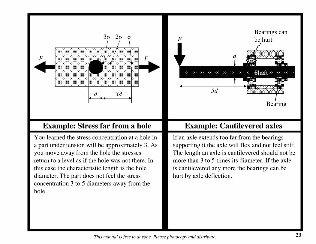
Example: Stress far from a hole Example: Cantilevered axles
If an axle extends too far from the bearings
supporting it the axle will flex and not feel stiff.
The length an axle is cantilevered should not be
more than 3 to 5 times its diameter. If the axle
is cantilevered any more the bearings can be
hurt by axle deflection.
You learned the stress concentration at a hole in
a part under tension will be approximately 3. As
you move away from the hole the stresses
return to a level as if the hole was not there. In
this case the characteristic length is the hole
diameter. The part does not feel the stress
concentration 3 to 5 diameters away from the
hole.
F
σ3σ
F
d 3d
2σ
Bearing
Shaft
F
5d
d
Bearings can
be hurt

Where useful
This manual is free to anyone. Please photocopy and distribute. 24
Description
If you want a frame or any kind of structure to
be stiff you should design the components of
the structure to be close together. A structural
loop is a visual way of representing how forces
travel through a structure. If the path the forces
take is narrow, the structure will be stiff. For
example, picture the forces that travel through
the caster frame. The forces start at the ground
and move up through the caster barrel. At the
top of the barrel they travel into the frame, loop
around the frame, and come back to the bottom
of the barrel. Now imagine if the caster frame
was very long – the structural loop would be
larger and the frame would be less stiff.
Imagine you are evaluating whether to use two
different frame layouts. One frame is a narrow
rectangle and another is a long rectangle. Each
frame has a force applied to the end, as shown
in the figure. Follow the force flow through the
frame and back to the point where the force is
applied. The narrow frame will be stiffer
because it has a tighter structural loop.
Structural loops
Frame
Caster frame
Example: Structural loops in frames
Footrests
F
F
More stiffLess stiff
Fo
rce flow
Force flow

Where useful
This manual is free to anyone. Please photocopy and distribute. 25
Description
The golden ratio, 1.618 to 1, is a proportion
commonly found in nature that is also useful in
many engineering applications. Your body is
built around this ratio; it is approximately the
ratio between your overall height and the
distance from your hips to the ground. Many
other animals and plants are built around this
proportion. When used in engineering the
golden ratio makes devices look aesthetically
pleasing and perform well. For example, the
distance between the tires along the length of a
car is usually about 1.6 times the width of the
car.
Look at the different doors in the above
example. Which one looks the most attractive?
The door that fits the golden ratio has the most
pleasing proportions.
Golden ratio
Frame
Axles
Example: Door proportions
Bearings
Casters
Footrests 1
1.6
1
1
1/3
1
26This manual is free to anyone. Please photocopy and distribute.
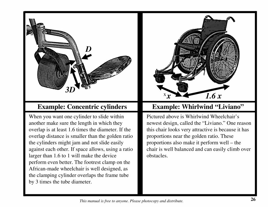
Example: Concentric cylinders Example: Whirlwind “Liviano”
Pictured above is Whirlwind Wheelchair’s
newest design, called the “Liviano.” One reason
this chair looks very attractive is because it has
proportions near the golden ratio. These
proportions also make it perform well – the
chair is well balanced and can easily climb over
obstacles.
When you want one cylinder to slide within
another make sure the length in which they
overlap is at least 1.6 times the diameter. If the
overlap distance is smaller than the golden ratio
the cylinders might jam and not slide easily
against each other. If space allows, using a ratio
larger than 1.6 to 1 will make the device
perform even better. The footrest clamp on the
African-made wheelchair is well designed, as
the clamping cylinder overlaps the frame tube
by 3 times the tube diameter.
xx 1.6 x
D
3D

Where useful
This manual is free to anyone. Please photocopy and distribute. 27
Description
An object can move 6 different ways, each of
which is called a Degree of Freedom (DOF); it
can rotate in 3 different DOFs and translate
(move in a strait line) in 3 different DOFs. Any
movement an object makes is composed of
some or all of these DOFs. You can constrain
DOFs to limit an object’s movement. Exact
constraint design is a method of using only one
constraint for each unwanted DOF. As you will
see in the examples, over constraining objects is
often necessary but in other instances can make
them deform or break.
The cube shown is not touching anything so it
has 6 DOFs: 3 rotational (curved arrows) and 3
translational (strait arrows). The 3-legged milk
stool has three points that touch the ground.
Each point acts as a constraint, thus the stool
has only 3 DOFs. From geometry, 2 points
define a line and 3 points define a plane. No
matter how rough the surface on which the
stool sits, three legs will always touch 3 points
that define the plane of the ground. This is why
a milk stool does not rock back and forth, no
matter what kind of ground it is on.
Exact constraint
Frame
Axles
Example: DOFs of objects
Bearings
Casters
FootrestsDOFs of free-
floating cube
Z
θZ
Y θY
X
θX
Exactly constrained
milk stool
Plane of the
ground
Contact
points
28This manual is free to anyone. Please photocopy and distribute.
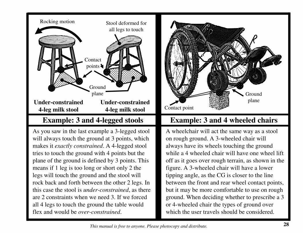
Example: 3 and 4-legged stools Example: 3 and 4 wheeled chairs
A wheelchair will act the same way as a stool
on rough ground. A 3-wheeled chair will
always have its wheels touching the ground
while a 4 wheeled chair will have one wheel lift
off as it goes over rough terrain, as shown in the
figure. A 3-wheeled chair will have a lower
tipping angle, as the CG is closer to the line
between the front and rear wheel contact points,
but it may be more comfortable to use on rough
ground. When deciding whether to prescribe a 3
or 4-wheeled chair the types of ground over
which the user travels should be considered.
As you saw in the last example a 3-legged stool
will always touch the ground at 3 points, which
makes it exactly constrained. A 4-legged stool
tries to touch the ground with 4 points but the
plane of the ground is defined by 3 points. This
means if 1 leg is too long or short only 2 the
legs will touch the ground and the stool will
rock back and forth between the other 2 legs. In
this case the stool is under-constrained, as there
are 2 constraints when we need 3. If we forced
all 4 legs to touch the ground the table would
flex and would be over-constrained.
Under-constrained
4-leg milk stool
Ground
plane
Contact
points
Rocking motion
Under-constrained
4-leg milk stool
Stool deformed for
all legs to touch
Ground
plane
Contact point
Where useful
This manual is free to anyone. Please photocopy and distribute. 29
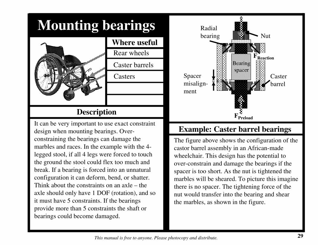
Description
It can be very important to use exact constraint
design when mounting bearings. Over-
constraining the bearings can damage the
marbles and races. In the example with the 4-
legged stool, if all 4 legs were forced to touch
the ground the stool could flex too much and
break. If a bearing is forced into an unnatural
configuration it can deform, bend, or shatter.
Think about the constraints on an axle – the
axle should only have 1 DOF (rotation), and so
it must have 5 constraints. If the bearings
provide more than 5 constraints the shaft or
bearings could become damaged.
The figure above shows the configuration of the
castor barrel assembly in an African-made
wheelchair. This design has the potential to
over-constrain and damage the bearings if the
spacer is too short. As the nut is tightened the
marbles will be sheared. To picture this imagine
there is no spacer. The tightening force of the
nut would transfer into the bearing and shear
the marbles, as shown in the figure.
Mounting bearings
Rear wheels
Caster barrels
Example: Caster barrel bearings
Casters
FPreload
Nut
Bearing
spacer
Radial
bearing
Caster
barrel
Spacer
misalign-
ment
FReaction

30This manual is free to anyone. Please photocopy and distribute.
Example: Under-constrained and exactly constrained caster barrel bearings
In the caster barrel the assembly, if the spacer is too long the bearings will be under-constrained and
able to slide up and down a little. This case is better than over constraining the bearings. No matter
how precisely the spacer and caster barrel are made they will not be perfect – the assembly will either
be over or under-constrained. There is a way to assemble the bearings so they are exactly constrained,
as shown in the second picture of the figure. In this design all the forces from the nut are transferred
through the bearing race and not through the marbles. Nut tightness will never harm the marbles. Study
the assembly – it cannot slide up and down because the internal threaded nut holts the assembly in
place.
FPreload
External
thread nut
Bearing
spacer
Radial
bearingNut
Caster
Barrel
FReaction

Where useful
This manual is free to anyone. Please photocopy and distribute. 31
Description
Radial bearings are designed to take radial
loads. Angular contact bearings are designed to
take radial and axial loads. An axial load is a
force acting in the direction of the center of the
shaft and a radial load is a force acting
perpendicular to the shaft, as shown in the
example. It is the job of an engineer to
determine what kinds of forces will act on a
bearing (radial, axial, or both), and choose the
best bearing for that particular machine.
The figure above shows a radial and an angular
contact bearing. Notice how the races of each
bearing are different. The angular contact
bearing has angled races so it can support both
radial and axial forces. The radial bearing is not
good for axial forces. There is not much area of
the race to support the marbles when they are
loaded in the axial direction.
Bearing types
Rear wheels
Caster barrels
Example: Types of bearings
Casters
Radial bearing Angular contact
bearings
www.ntnamerica.comwww.gsportbmx.co.uk
Fradial
Freaction
Race Marble
Fradial
Freaction
Race
Marble
Faxial

32This manual is free to anyone. Please photocopy and distribute.
Example: Angular contact bearings used in bicycles
Angular contact bearings are used in bicycles because bicycles experience both radial and axial forces.
These bearings may be good alternatives to the radial bearings used in wheelchairs, especially in caster
barrels where the highest forces are axial. Different types of angular contact bearings are made for
different areas of the bicycle, such as the hubs and stem. Bicycle bearings are usually over-constrained
but are designed with a lock nut. When you install a bicycle bearing first tighten the marbles so they
are securely in place, and then tighten the locknut to keep the assembly from coming apart.
The figure above shows a concept for a caster barrel and caster design using bicycle hubs. The caster
barrel is made from a bicycle hub welded directly to the wheelchair frame. Some wheelchair
manufacturers already use bicycle hubs pressed into molded rubber casters – the African-made
wheelchair shown throughout this manual has this caster design.
Stem bearings
Assembled view
Disassembled view
Front hub
Assembled view
Disassembled view
Frame
Hub

Where useful
This manual is free to anyone. Please photocopy and distribute. 33
Description
It is important to keep bearings lubricated with
grease. Grease is composed of soap and oil. The
soap keeps the oil from running out of the
bearing and insures it remains under the bearing
marbles. When the bearing is lubricated
properly the marbles never touch the race and
actually roll on a thin film of oil. It is very
important to keep bearings clean, as small
particles of dirt can damage the marbles and
races.
The figure above shows grease wedged between
the bearing marble and race. Grease becomes
very stiff and acts almost like a solid when it is
squeezed between the marble and the race in
the contact zone. This is how it prevents getting
squeezed out when the bearing is loaded. The
grease film is very thin, only a few millionths
of a meter thick. It is extremely important to
keep the bearings clean, as dirt within the
grease film can damage the marbles and races.
Bearing lubrication
Rear wheels
Caster barrels
Example: Grease under marbles
Casters
F
Marble
Grease
Race
Contact
zone

Where useful
This manual is free to anyone. Please photocopy and distribute. 34
Description
Lean manufacturing is a term used to describe
manufacturing practices and strategies that
reduce cost and production time. The lean
manufacturing techniques presented in this
section may or may not be useful to your
workshop. Before implementing these
strategies the workshop should estimate or run
an experiment to see whether or not the strategy
can save time and/or money.
OutsourcingOutsourcing is a term to describe hiring another
company to make components instead of
making them within your wheelchair workshop.
Many wheelchair workshops already outsource
caster wheels by having the rubber molded at
another facility. For parts that require many
hours to fabricate or the use of a special
machine, one should consider the cost and
benefit of producing the part within the
wheelchair workshop or at another company.
For example, there are wheelchair parts which
need to be turned on a lathe. If the profit made
from those parts takes more than a few years to
equal the cost of the lathe, those parts should
probably be outsourced to a company that
specializes in metal fabrication. The money that
would be used to buy a lathe could be invested
elsewhere within the workshop.
Pull method for acquiring partsThe pull method is a strategy where a company
buys parts only when needed. Instead of storing
a large inventory of parts, the company will
make or order parts when necessary. There are
cases when parts do need to be stored, for
Lean manufacturing
Frame
Axles
Bearings
Casters
Footrests

35This manual is free to anyone. Please photocopy and distribute.
have to check that the tubing size is practical.
Even if it has the best strength to weight it
might not be a sensible choice. For example, if
the diameter is 10 centimeters and the weight is
50 kilograms per meter, the tubing is too big
and heavy to be used in a wheelchair.
Utilize purchased partsJust like you do with outsourcing, consider both
material and labor costs of parts that have to be
fabricated. If you can buy parts that are made in
China or India, they may save you a lot of
money. You will have to compare cost with
reliability of the parts, as you want to maintain
high-quality wheelchairs.
Using bicycle partsThe use of bicycle parts in wheelchairs has
many advantages. Bicycle parts are often
available throughout Africa, they can be easily
disassembled to be cleaned and greased, and
they are easily repaired by bicycle mechanics.
Bicycle parts are often much cheaper than other
parts that perform the same function. For
example, in Tanzania the majority of the parts
in hand-powered tricycles are purchased bicycle
example if they can only be bought in large
quantities or if it is faster to make many parts at
one time. The pull strategy is sometimes useful
because it decreases inventory size, which
reduces the required workshop size. Also, by
purchasing a few parts at a time the company
can avoid paying a lot of money at once.
Minimal weight designWeight should be considered when designing a
wheelchair. Reducing weight not only makes
the chair easier to use, it also lowers the
material cost. One weight-reducing strategy is
to design your frame so all the features add
strength. Try to avoid features that add weight
but do not add strength. Another strategy is to
maximize the strength and minimize the weight
of the frame tubing. Review the section of this
manual on volume and moment of inertia
calculations. Calculate the moment of inertia
and weight for a 1 meter section of all the
available sizes of steel tubing you can buy.
Then find which tubing geometry has the
highest ratio of moment of inertia divided by
the weight. This tube will have the best strength
to weight ratio and can be used to make the
strongest frame at the least weight. You will

36This manual is free to anyone. Please photocopy and distribute.
parts. By using these parts tricycle
manufacturers have to fabricate very few items,
which greatly reduces their production cost.
They are able to sell tricycles for $100US less
than most Tanzanian-made wheelchairs.
Single jig/symmetric frame designA wheelchair has a left and right side. Some
components are only used on one side or the
other. Manufacturing time for a wheelchair can
be reduced if parts can be used on both sides.
For example, if the frame components on each
side of a wheelchair were the same, only one jig
would be required during fabrication. Making
“universal” parts which work on both sides of
the chair also decreases the number of different
parts you have to keep in your inventory.