meca0063 : driveline systems...h. heisler. « vehicle and engine technology ». 2nd edition. (1999)...
TRANSCRIPT
MECA0063 : Driveline systems
Pierre DuysinxResearch Center in Sustainable Automotive
Technologies of University of Liege
Academic Year 2019-2020
1
Bibliography
◼ T. Gillespie. « Fundamentals of vehicle Dynamics », 1992, Society of Automotive Engineers (SAE)
◼ J. Happian-Smith ed. « An introduction to modern vehicle design ». Butterworth-Heinemann. (2002)
◼ H. Heisler. « Vehicle and Engine Technology ». 2nd edition. (1999) Butterworth Heineman.
◼ H. Heisler. “Advanced Vehicle Technology”. 2nd edition. Elsevier Butterworh Heinemann (2002)
◼ D. Crolla. Ed. “Automotive engineering – Powertrain, chassis system, and vehicle body”. Elsevier Butterworh Heinemann (2009)
◼ R. Langoria. « Vehicle Power Transmission: Concepts, Components, and Modelling ». Lecture notes of Vehicle System Dynamics and Control, The University of Texas at Austin, 2004.
2

Bibliography
◼ INTERNET ressources:
◼ http://www.howstuffworks.com
◼ http://www.carbibles.com/transmission_bible.html
3
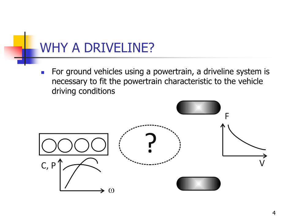
WHY A DRIVELINE?
◼ For ground vehicles using a powertrain, a driveline system is necessary to fit the powertrain characteristic to the vehicle driving conditions
4
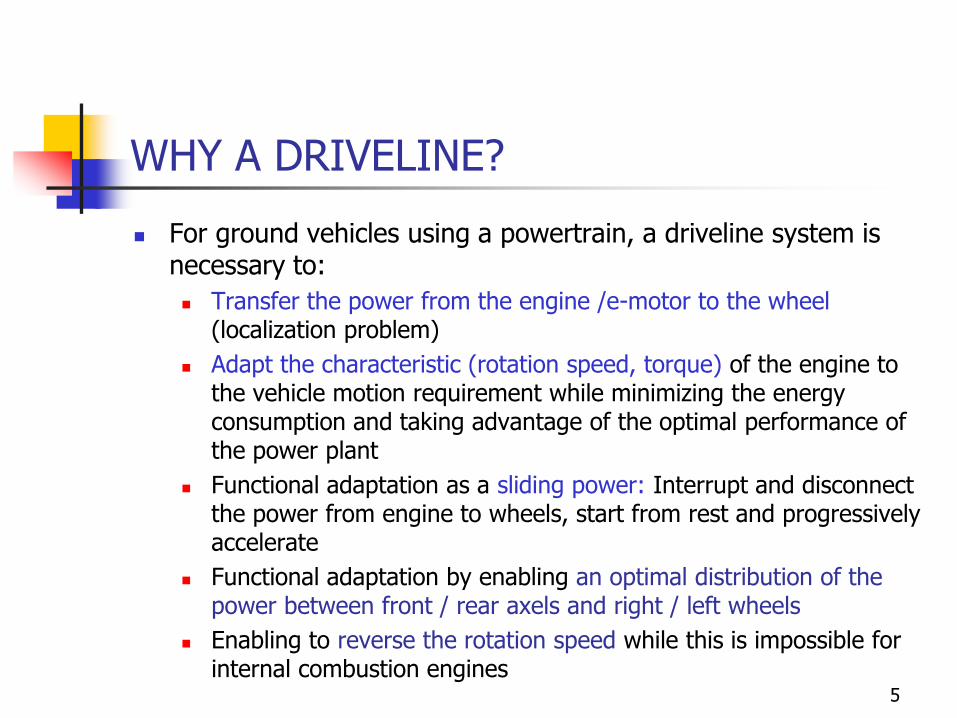
WHY A DRIVELINE?
◼ For ground vehicles using a powertrain, a driveline system is necessary to:
◼ Transfer the power from the engine /e-motor to the wheel (localization problem)
◼ Adapt the characteristic (rotation speed, torque) of the engine to the vehicle motion requirement while minimizing the energy consumption and taking advantage of the optimal performance of the power plant
◼ Functional adaptation as a sliding power: Interrupt and disconnect the power from engine to wheels, start from rest and progressively accelerate
◼ Functional adaptation by enabling an optimal distribution of the power between front / rear axels and right / left wheels
◼ Enabling to reverse the rotation speed while this is impossible for internal combustion engines
5
WHY A DRIVELINE?
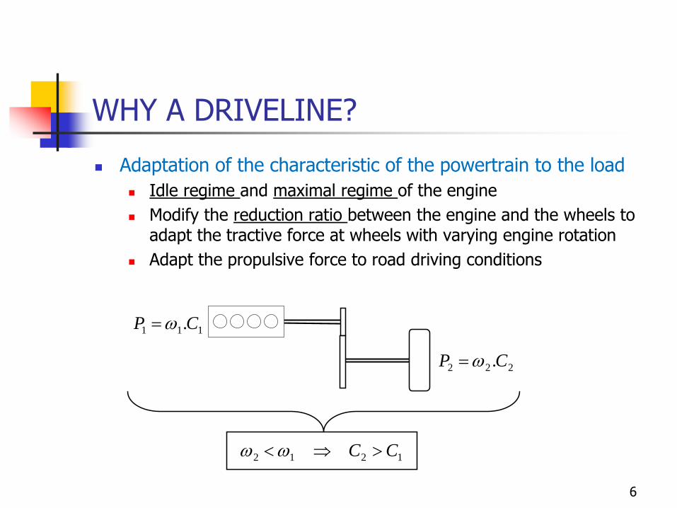
◼ Adaptation of the characteristic of the powertrain to the load
◼ Idle regime and maximal regime of the engine
◼ Modify the reduction ratio between the engine and the wheels to adapt the tractive force at wheels with varying engine rotation
◼ Adapt the propulsive force to road driving conditions
222 .CP =
111 .CP =
1212 CC
6
WHY A DRIVELINE?
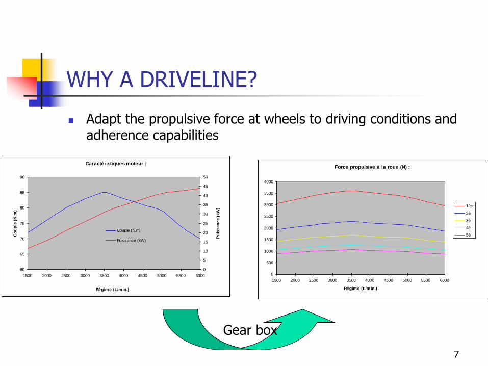
◼ Adapt the propulsive force at wheels to driving conditions and adherence capabilities
Caractéristiques moteur :
60
65
70
75
80
85
90
1500 2000 2500 3000 3500 4000 4500 5000 5500 6000
Régime (t./min.)
Co
up
le (
N.m
)
0
5
10
15
20
25
30
35
40
45
50
Pu
issan
ce (
kW
)
Couple (N.m)
Puissance (kW)
Force propulsive à la roue (N) :
0
500
1000
1500
2000
2500
3000
3500
4000
1500 2000 2500 3000 3500 4000 4500 5000 5500 6000
Régime (t./min.)
1ère
2è
3è
4è
5è
Gear box
7
WHY A DRIVELINE?
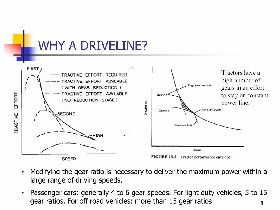
• Modifying the gear ratio is necessary to deliver the maximum power within a large range of driving speeds.
• Passenger cars: generally 4 to 6 gear speeds. For light duty vehicles, 5 to 15 gear ratios. For off road vehicles: more than 15 gear ratios 8
WHY A DRIVELINE?
◼ Functional adaptation as a sliding power
◼ Enabling the interruption of the power flow to the wheels,
◼ Enabling the coupling and uncoupling of the engine and of the wheels with a progressive maneuver
◼ Functional adaptation of the power by managing the repartition of the power split between the tires :
◼ Optimal distribution between front and left/right wheels
◼ Distribution in turn
◼ Distribution of power in low grip conditions: anti-skip and limited slip operation
◼ Stability control
9
DRIVELINE SYSTEM
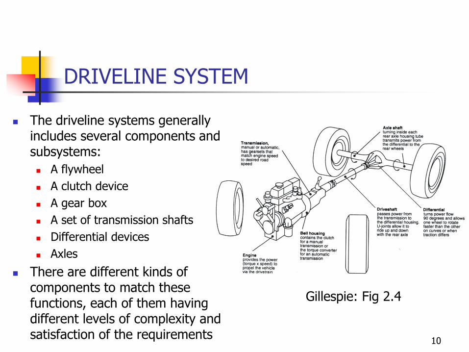
◼ The driveline systems generally includes several components and subsystems:
◼ A flywheel
◼ A clutch device
◼ A gear box
◼ A set of transmission shafts
◼ Differential devices
◼ Axles
◼ There are different kinds of components to match these functions, each of them having different levels of complexity and satisfaction of the requirements
Gillespie: Fig 2.4
10
DRIVELINE SYSTEM
11
DRIVELINE SYSTEM
12
DRIVELINE SYSTEM
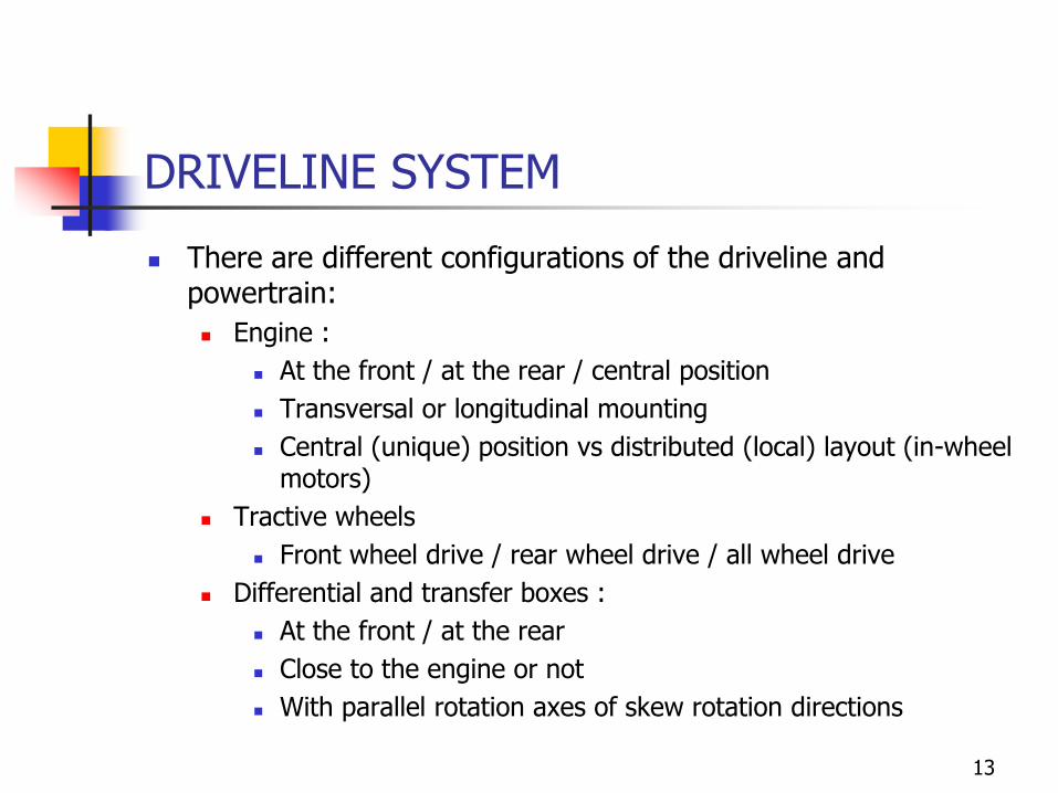
◼ There are different configurations of the driveline and powertrain:
◼ Engine :
◼ At the front / at the rear / central position
◼ Transversal or longitudinal mounting
◼ Central (unique) position vs distributed (local) layout (in-wheel motors)
◼ Tractive wheels
◼ Front wheel drive / rear wheel drive / all wheel drive
◼ Differential and transfer boxes :
◼ At the front / at the rear
◼ Close to the engine or not
◼ With parallel rotation axes of skew rotation directions
13
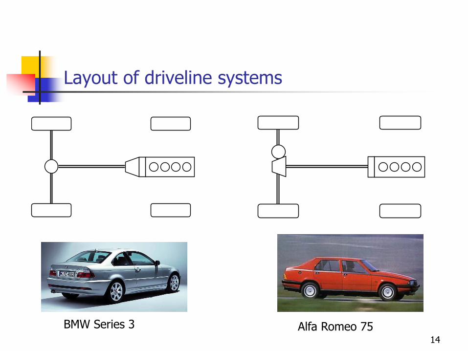
Layout of driveline systems
14
Alfa Romeo 75BMW Series 3
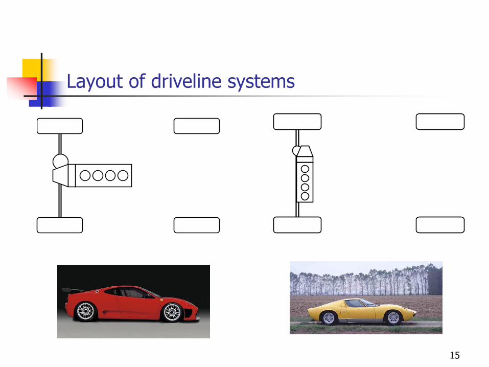
Layout of driveline systems
15
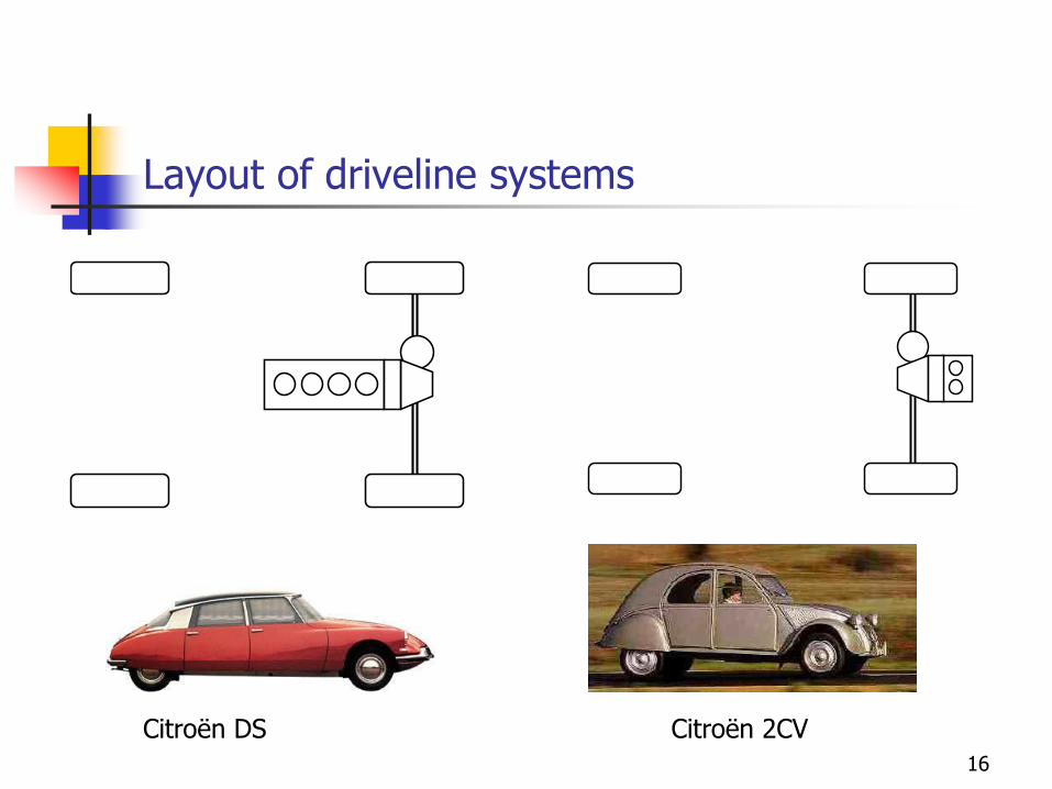
Layout of driveline systems
16
Citroën DS Citroën 2CV
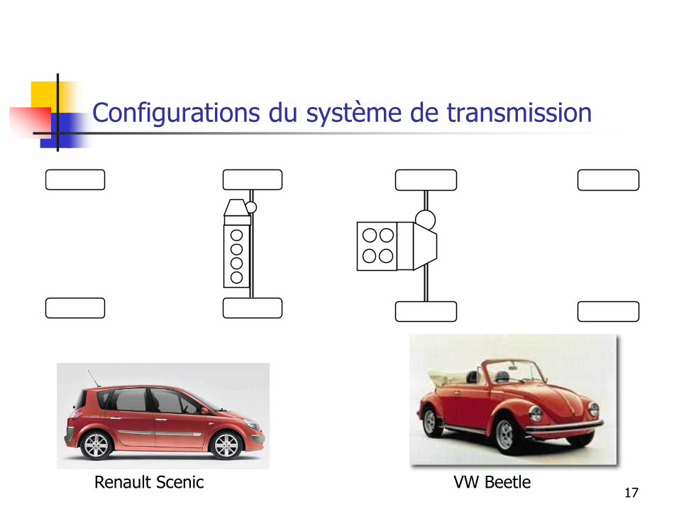
Configurations du système de transmission
17Renault Scenic VW Beetle
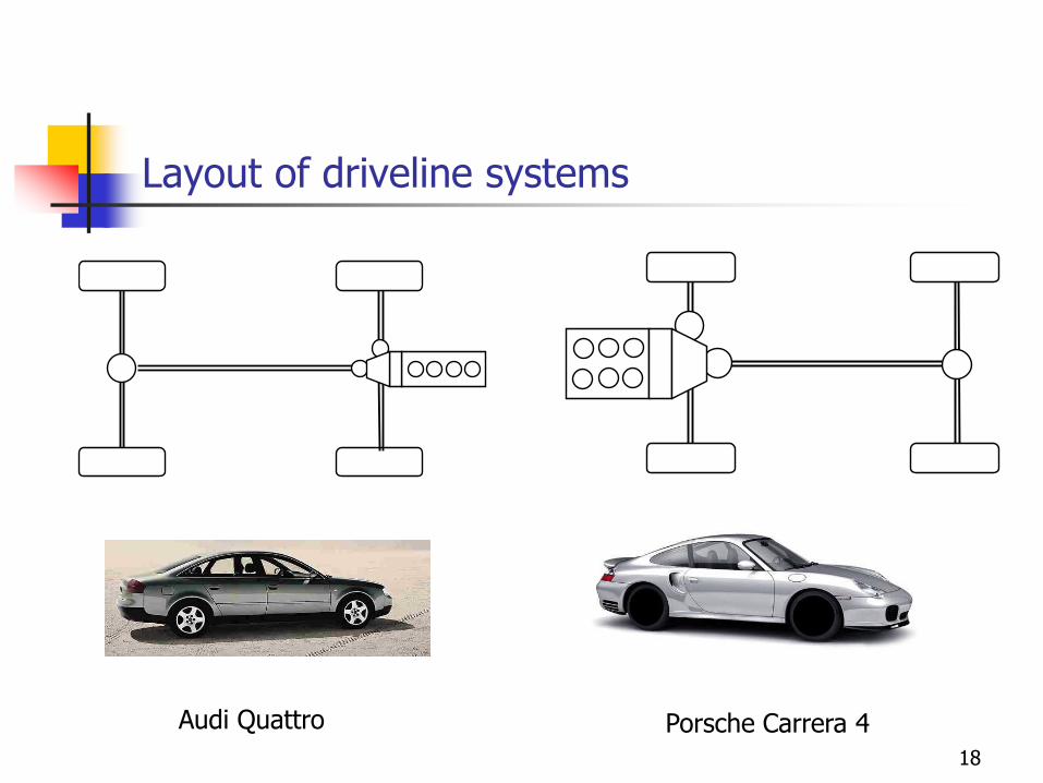
Layout of driveline systems
18
Porsche Carrera 4Audi Quattro
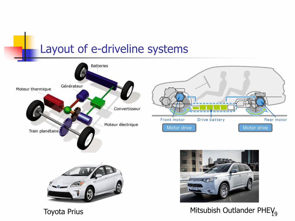
Layout of e-driveline systems
19Toyota Prius Mitsubish Outlander PHEV
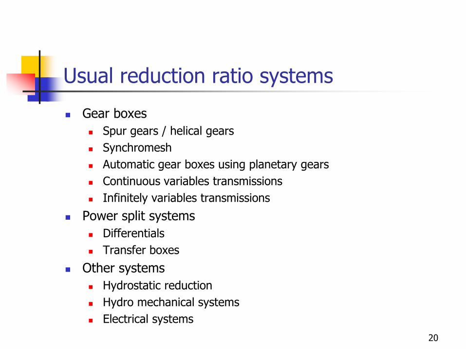
Usual reduction ratio systems
◼ Gear boxes
◼ Spur gears / helical gears
◼ Synchromesh
◼ Automatic gear boxes using planetary gears
◼ Continuous variables transmissions
◼ Infinitely variables transmissions
◼ Power split systems
◼ Differentials
◼ Transfer boxes
◼ Other systems
◼ Hydrostatic reduction
◼ Hydro mechanical systems
◼ Electrical systems
20
PERFORMANCE SPECIFICATIONS
21
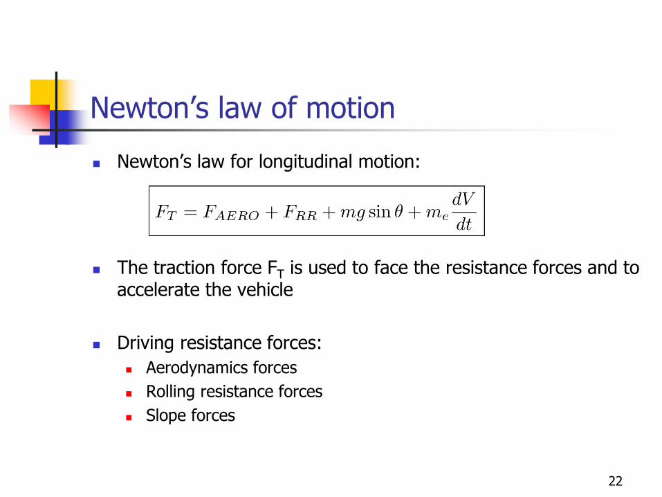
Newton’s law of motion
◼ Newton’s law for longitudinal motion:
◼ The traction force FT is used to face the resistance forces and to accelerate the vehicle
◼ Driving resistance forces:
◼ Aerodynamics forces
◼ Rolling resistance forces
◼ Slope forces
22
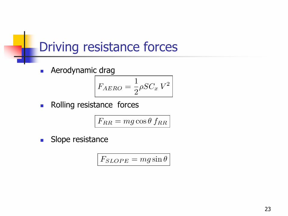
Driving resistance forces
◼ Aerodynamic drag
◼ Rolling resistance forces
◼ Slope resistance
23
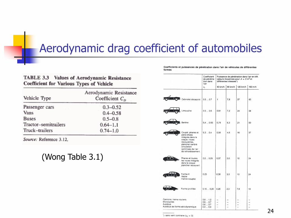
Aerodynamic drag coefficient of automobiles
(Wong Table 3.1)
24
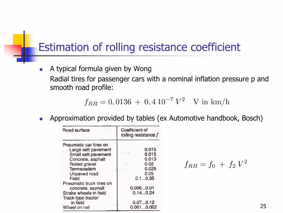
Estimation of rolling resistance coefficient
◼ A typical formula given by Wong
Radial tires for passenger cars with a nominal inflation pressure p and smooth road profile:
◼ Approximation provided by tables (ex Automotive handbook, Bosch)
25
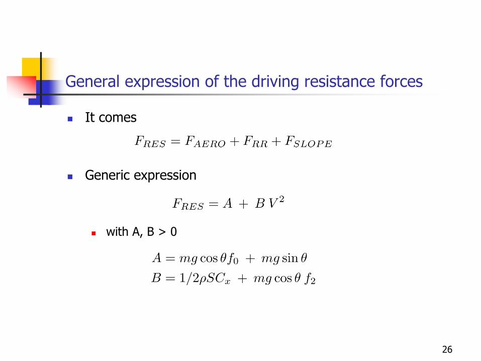
General expression of the driving resistance forces
◼ It comes
◼ Generic expression
◼ with A, B > 0
26
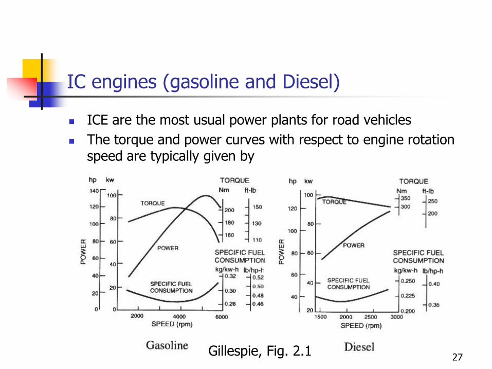
IC engines (gasoline and Diesel)
◼ ICE are the most usual power plants for road vehicles
◼ The torque and power curves with respect to engine rotation speed are typically given by
Gillespie, Fig. 2.127
Tractive power and forces
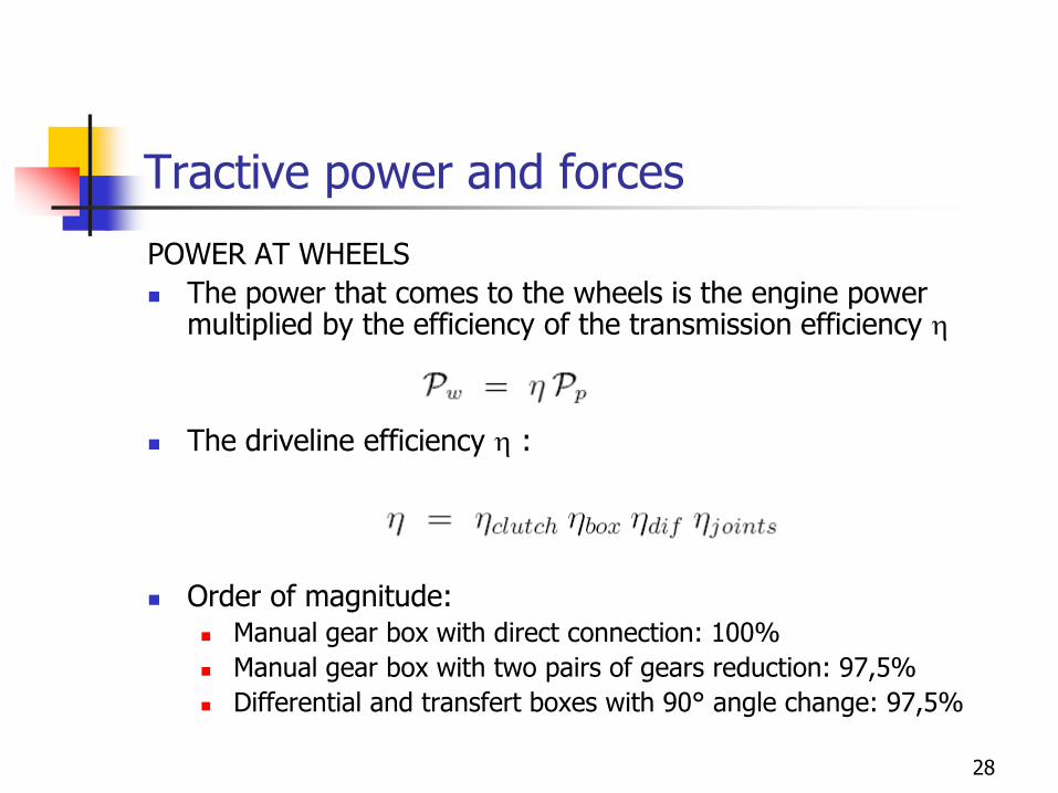
POWER AT WHEELS
◼ The power that comes to the wheels is the engine power multiplied by the efficiency of the transmission efficiency h
◼ The driveline efficiency h :
◼ Order of magnitude:◼ Manual gear box with direct connection: 100%
◼ Manual gear box with two pairs of gears reduction: 97,5%
◼ Differential and transfert boxes with 90° angle change: 97,5%
28
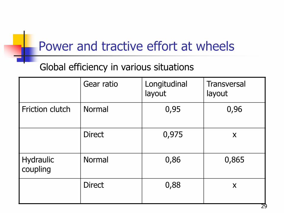
Power and tractive effort at wheels
Gear ratio Longitudinal layout
Transversal layout
Friction clutch Normal 0,95 0,96
Direct 0,975 x
Hydraulic coupling
Normal 0,86 0,865
Direct 0,88 x
Global efficiency in various situations
29
Tractive power and effort at wheels
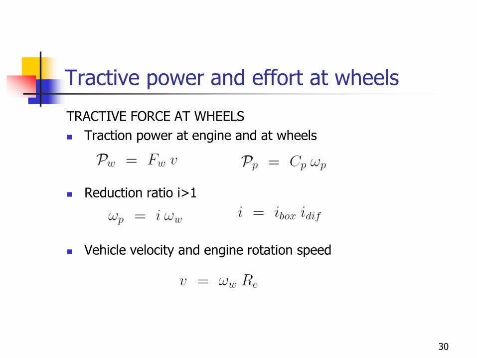
TRACTIVE FORCE AT WHEELS
◼ Traction power at engine and at wheels
◼ Reduction ratio i>1
◼ Vehicle velocity and engine rotation speed
30
Traction power and forces at wheels
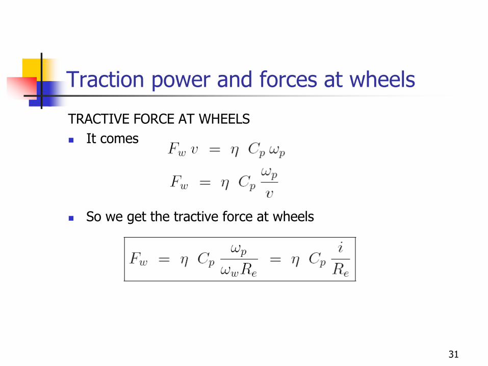
TRACTIVE FORCE AT WHEELS
◼ It comes
◼ So we get the tractive force at wheels
31
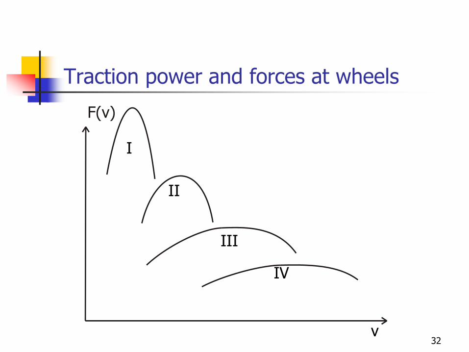
Traction power and forces at wheels
v
I
II
III
IV
32
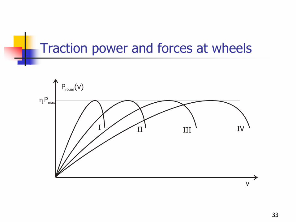
Traction power and forces at wheels
Proues(v)
v
h Pmax
I II III IV
33
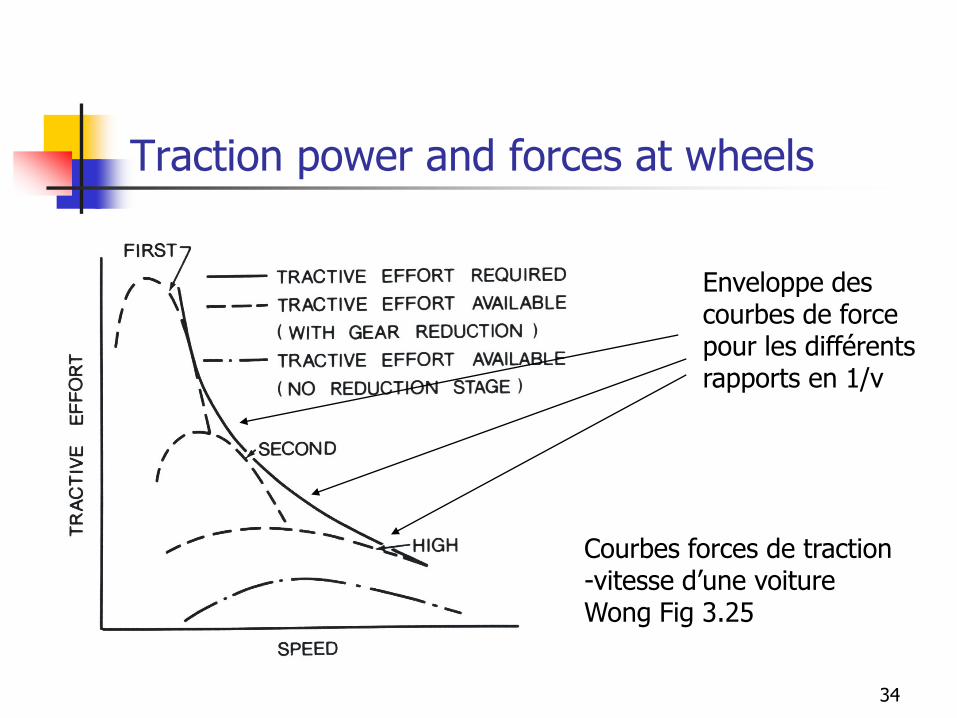
Traction power and forces at wheels
Enveloppe descourbes de forcepour les différents rapports en 1/v
Courbes forces de traction-vitesse d’une voitureWong Fig 3.25
34
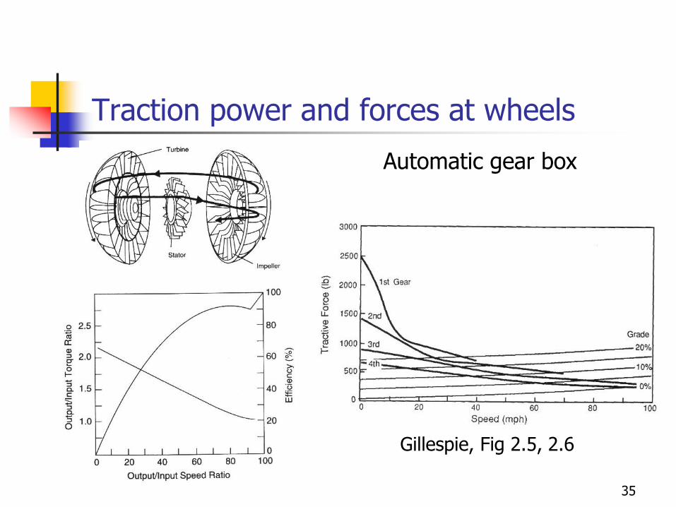
Traction power and forces at wheels
Gillespie, Fig 2.5, 2.6
Automatic gear box
35
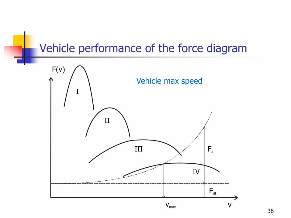
Vehicle performance of the force diagram
v
I
II
III
vmax
IV
Fa
Frlt
Vehicle max speed
36
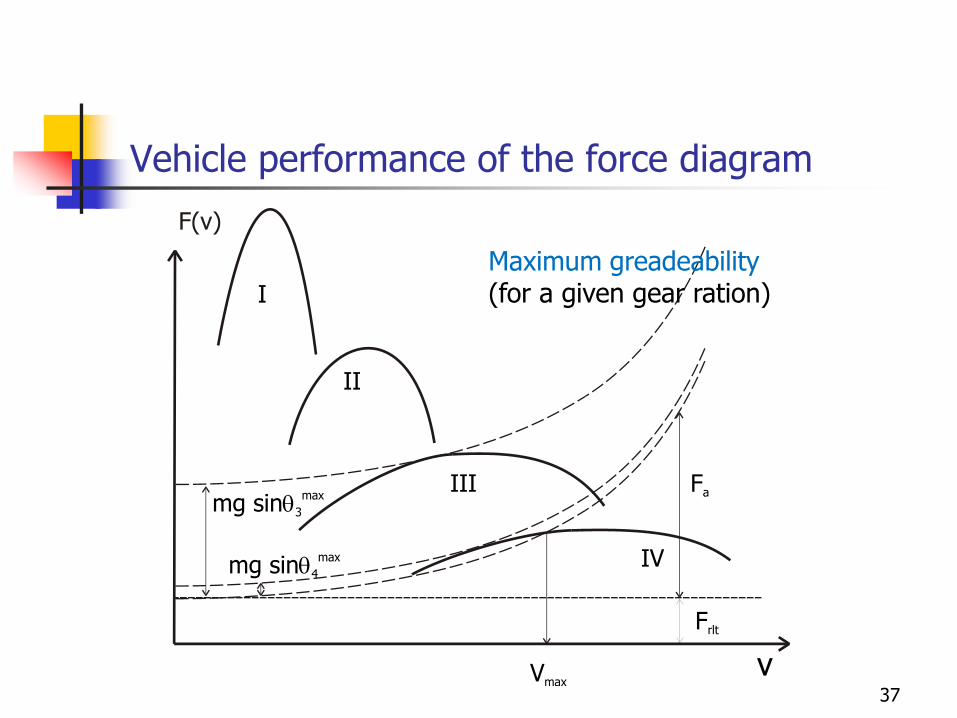
Vehicle performance of the force diagram
v
I
II
III
IV
Vmax
mg sin3
max
mg sin4
max
Fa
Frlt
Maximum greadeability(for a given gear ration)
37
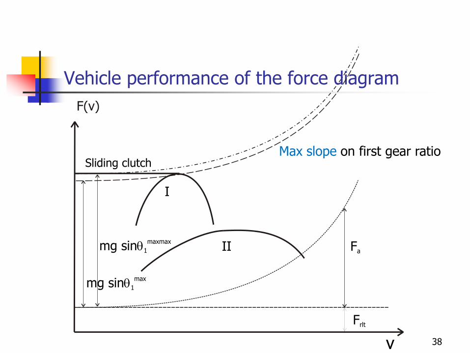
Vehicle performance of the force diagram
v
I
II
mg sin1
max
mg sin1
maxmax
Sliding clutch
Fa
Frlt
Max slope on first gear ratio
38
ENGINE FLYWHEEL
39
ENGINE FLYWHEEL
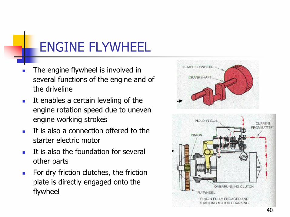
◼ The engine flywheel is involved in
several functions of the engine and of
the driveline
◼ It enables a certain leveling of the
engine rotation speed due to uneven
engine working strokes
◼ It is also a connection offered to the
starter electric motor
◼ It is also the foundation for several
other parts
◼ For dry friction clutches, the friction
plate is directly engaged onto the
flywheel
40
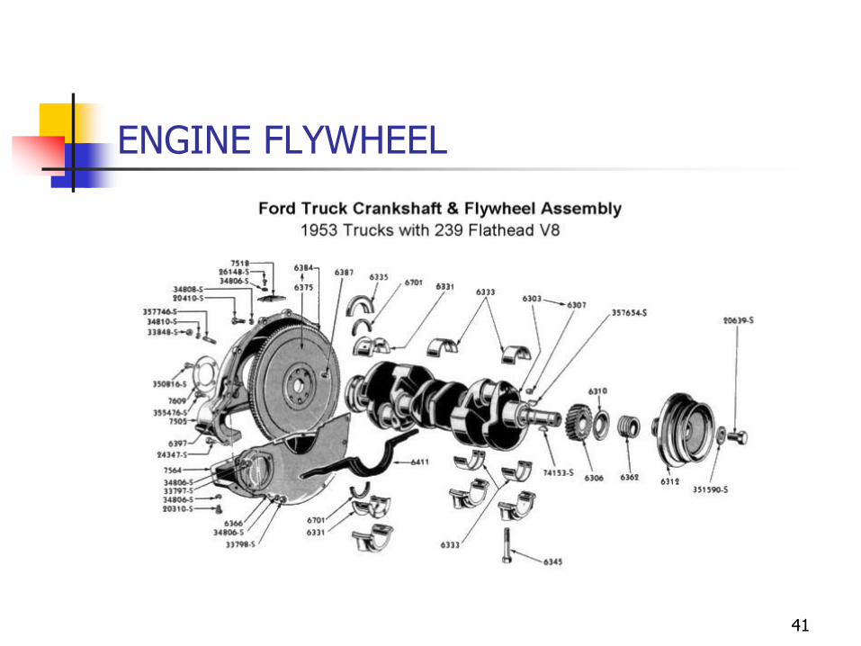
ENGINE FLYWHEEL
41

CLUTCH SYSTEMS
42
CLUTCH
◼ Functions:◼ The clutch is necessary to connect / disconnect the engine and the
wheels
◼ In a vehicle, the clutch is used to transmit the power flowing from the engine to the wheels while enabling to disconnect it during gear changes
◼ The clutch enables also to comply with engine idling speed while the vehicle is at rest without using the neutral position of the gear box
43
CLUTCH
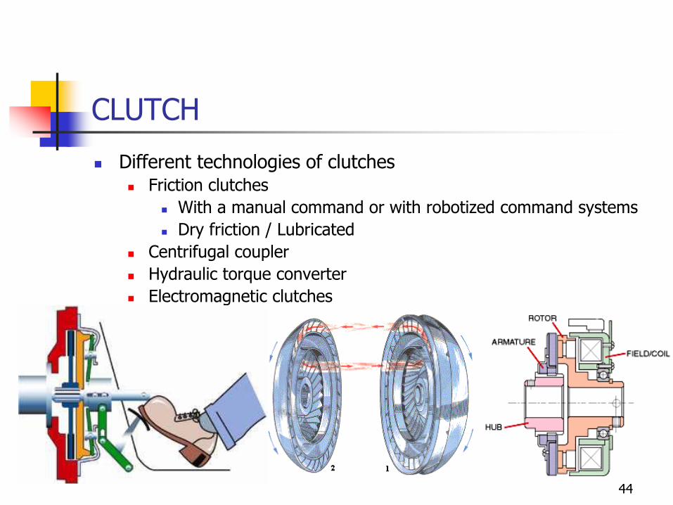
◼ Different technologies of clutches◼ Friction clutches
◼ With a manual command or with robotized command systems
◼ Dry friction / Lubricated
◼ Centrifugal coupler
◼ Hydraulic torque converter
◼ Electromagnetic clutches
44
Dry friction clutch
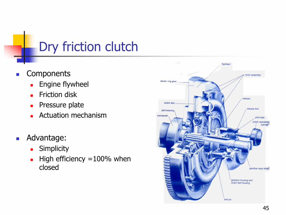
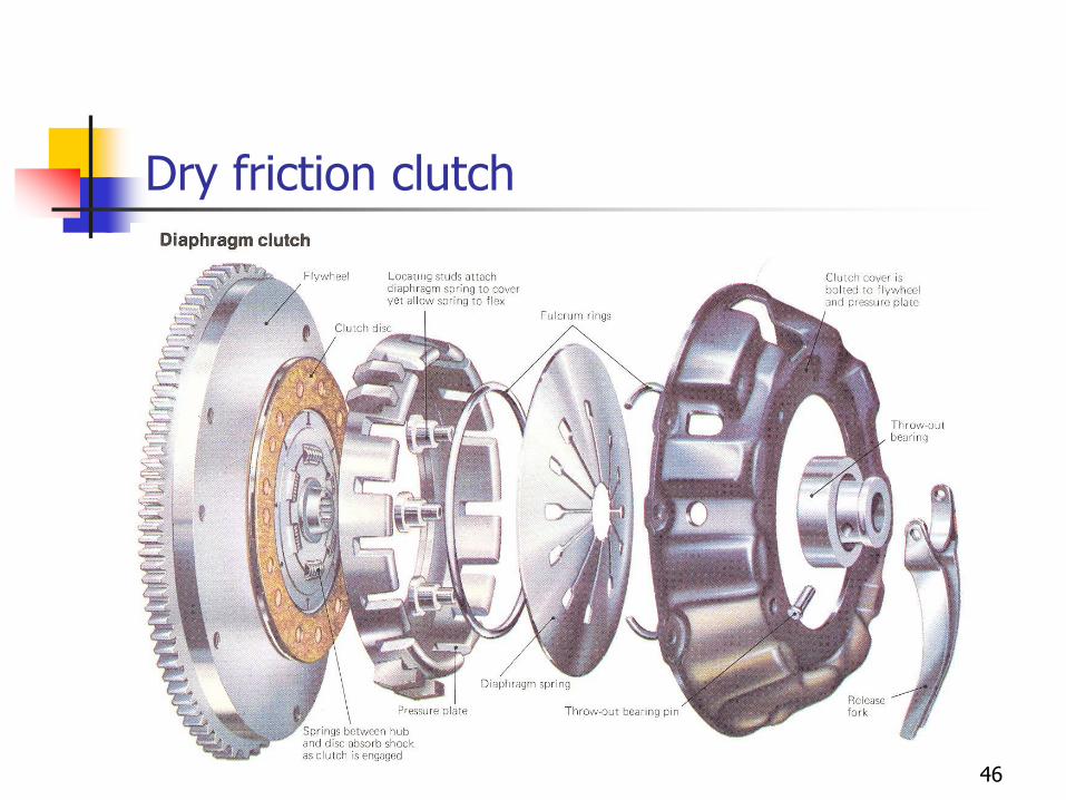
◼ Components
◼ Engine flywheel
◼ Friction disk
◼ Pressure plate
◼ Actuation mechanism
◼ Advantage:
◼ Simplicity
◼ High efficiency =100% when closed
45
Dry friction clutch
46
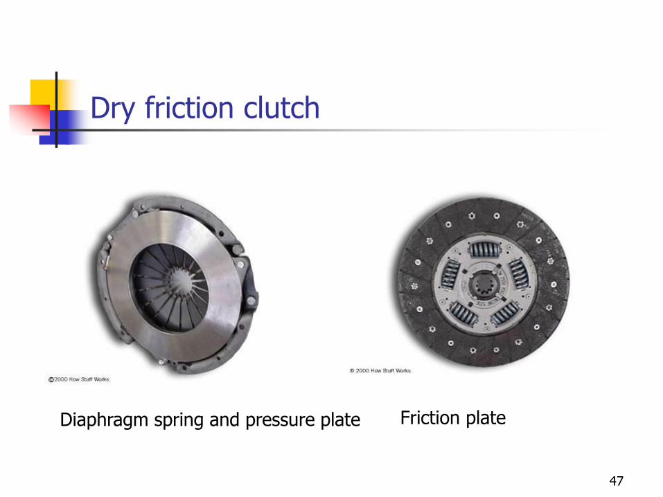
Dry friction clutch
Friction plateDiaphragm spring and pressure plate
47
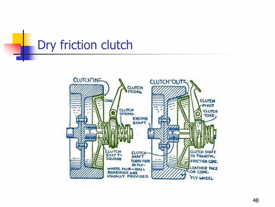
Dry friction clutch
48
Dry friction clutch
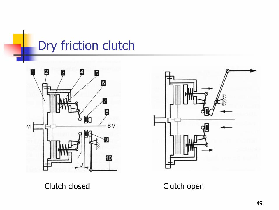
Clutch closed Clutch open
49
Dry friction clutch
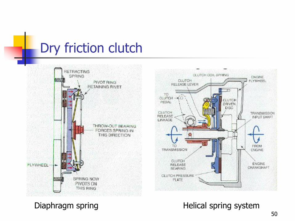
Diaphragm spring Helical spring system50
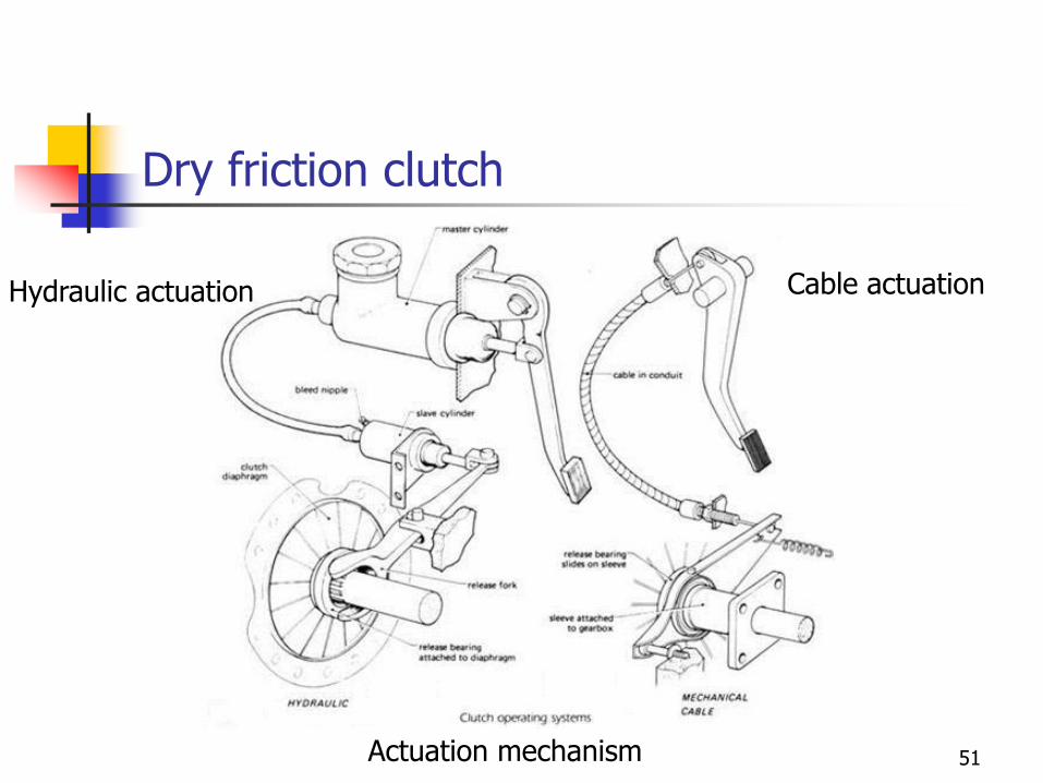
Dry friction clutch
Actuation mechanism 51
Cable actuationHydraulic actuation
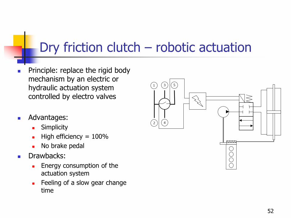
Dry friction clutch – robotic actuation
◼ Principle: replace the rigid body mechanism by an electric or hydraulic actuation system controlled by electro valves
◼ Advantages:
◼ Simplicity
◼ High efficiency = 100%
◼ No brake pedal
◼ Drawbacks:
◼ Energy consumption of the actuation system
◼ Feeling of a slow gear change time
1 3
4
5
2
52
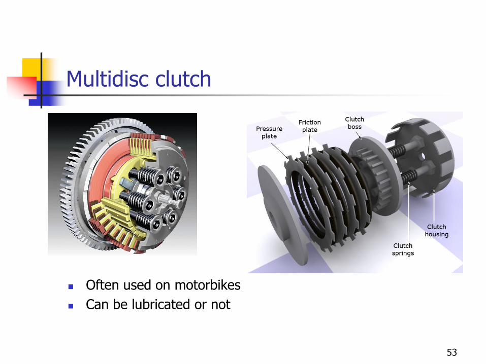
Multidisc clutch
◼ Often used on motorbikes
◼ Can be lubricated or not
53
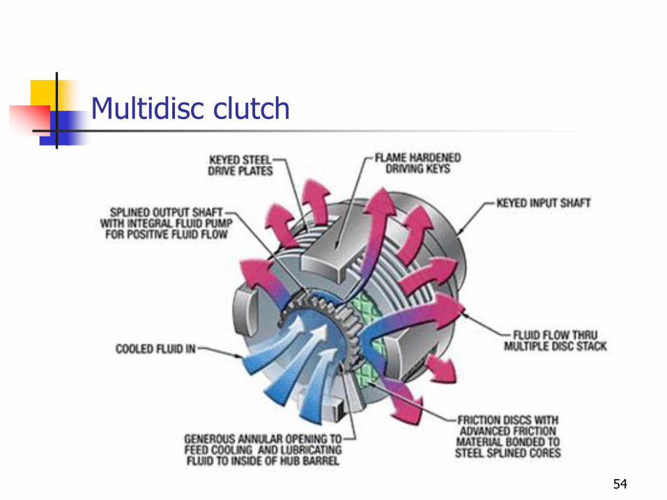
Multidisc clutch
54
Hydraulic transmission
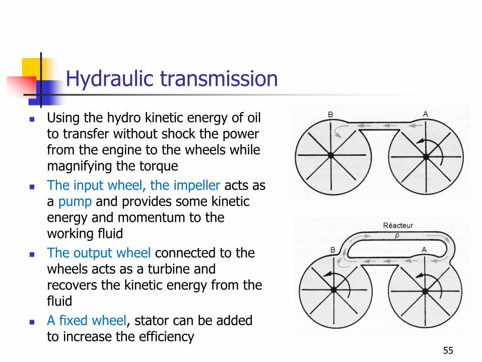
◼ Using the hydro kinetic energy of oil to transfer without shock the power from the engine to the wheels while magnifying the torque
◼ The input wheel, the impeller acts as a pump and provides some kinetic energy and momentum to the working fluid
◼ The output wheel connected to the wheels acts as a turbine and recovers the kinetic energy from the fluid
◼ A fixed wheel, stator can be added to increase the efficiency
55
Hydraulic torque converter
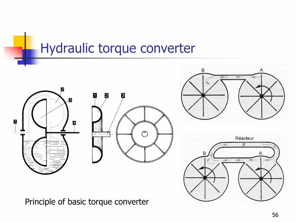
Principle of basic torque converter
56
Hydraulic torque converter
◼ Because of its working principle, the torque coupler naturally complies with the difference of rotation speed of input and output shafts
◼ Thus it is well adapted to start functions.
57
Hydraulic transmission
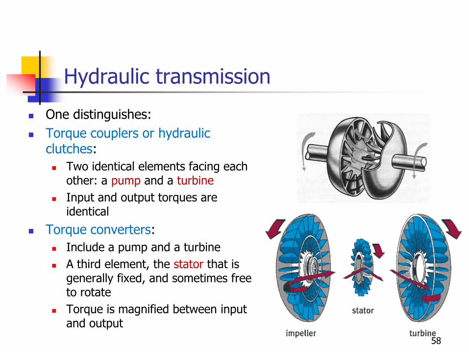
◼ One distinguishes:
◼ Torque couplers or hydraulic clutches:
◼ Two identical elements facing each other: a pump and a turbine
◼ Input and output torques are identical
◼ Torque converters:
◼ Include a pump and a turbine
◼ A third element, the stator that is generally fixed, and sometimes free to rotate
◼ Torque is magnified between input and output
58
Torque coupler
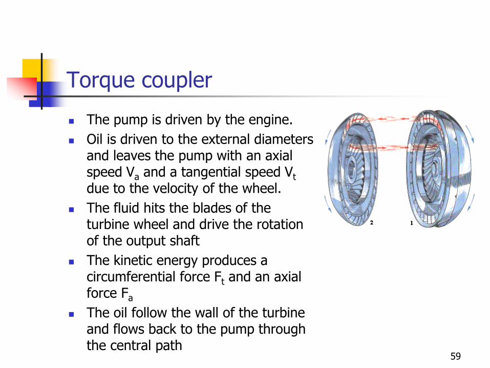
◼ The pump is driven by the engine.
◼ Oil is driven to the external diameters and leaves the pump with an axial speed Va and a tangential speed Vt
due to the velocity of the wheel.
◼ The fluid hits the blades of the turbine wheel and drive the rotation of the output shaft
◼ The kinetic energy produces a circumferential force Ft and an axial force Fa
◼ The oil follow the wall of the turbine and flows back to the pump through the central path
59
Hydraulic torque coupling
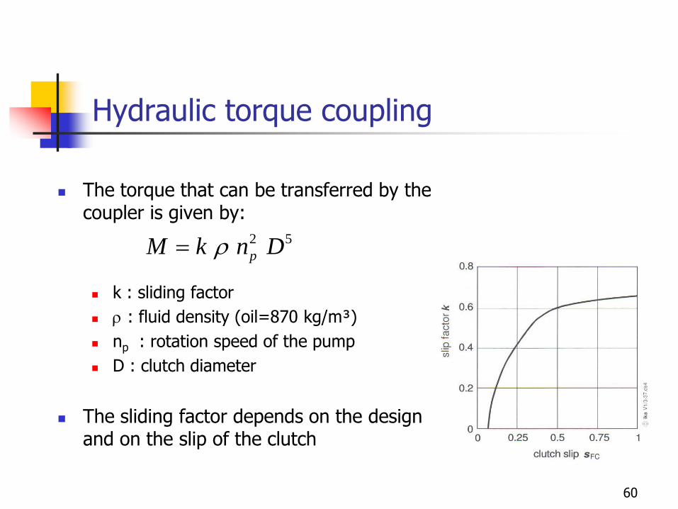
◼ The torque that can be transferred by the coupler is given by:
◼ k : sliding factor
◼ r : fluid density (oil=870 kg/m³)
◼ np : rotation speed of the pump
◼ D : clutch diameter
◼ The sliding factor depends on the design and on the slip of the clutch
2 5
pM k n Dr=
60
Hydraulic torque converter
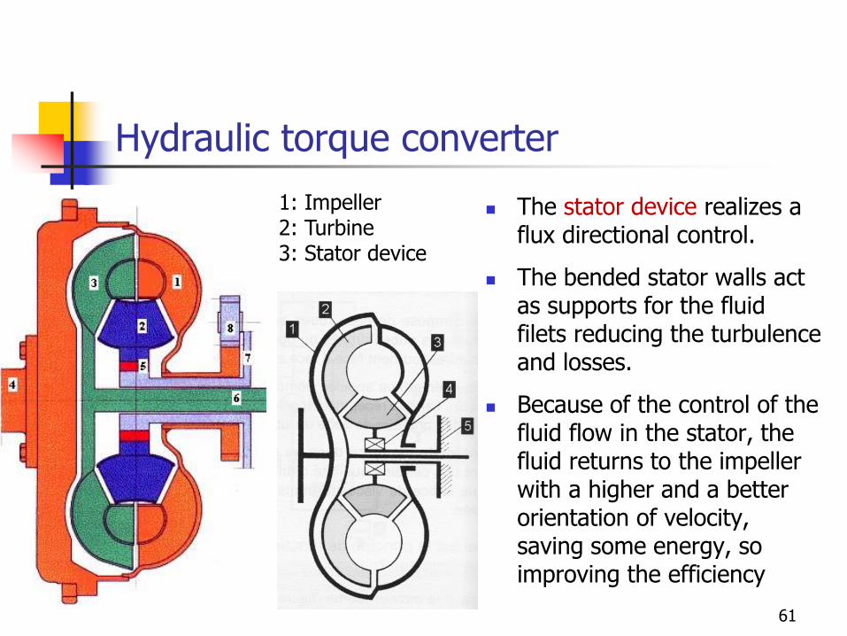
◼ The stator device realizes a flux directional control.
◼ The bended stator walls act as supports for the fluid filets reducing the turbulence and losses.
◼ Because of the control of the fluid flow in the stator, the fluid returns to the impeller with a higher and a better orientation of velocity, saving some energy, so improving the efficiency
1: Impeller2: Turbine3: Stator device
61
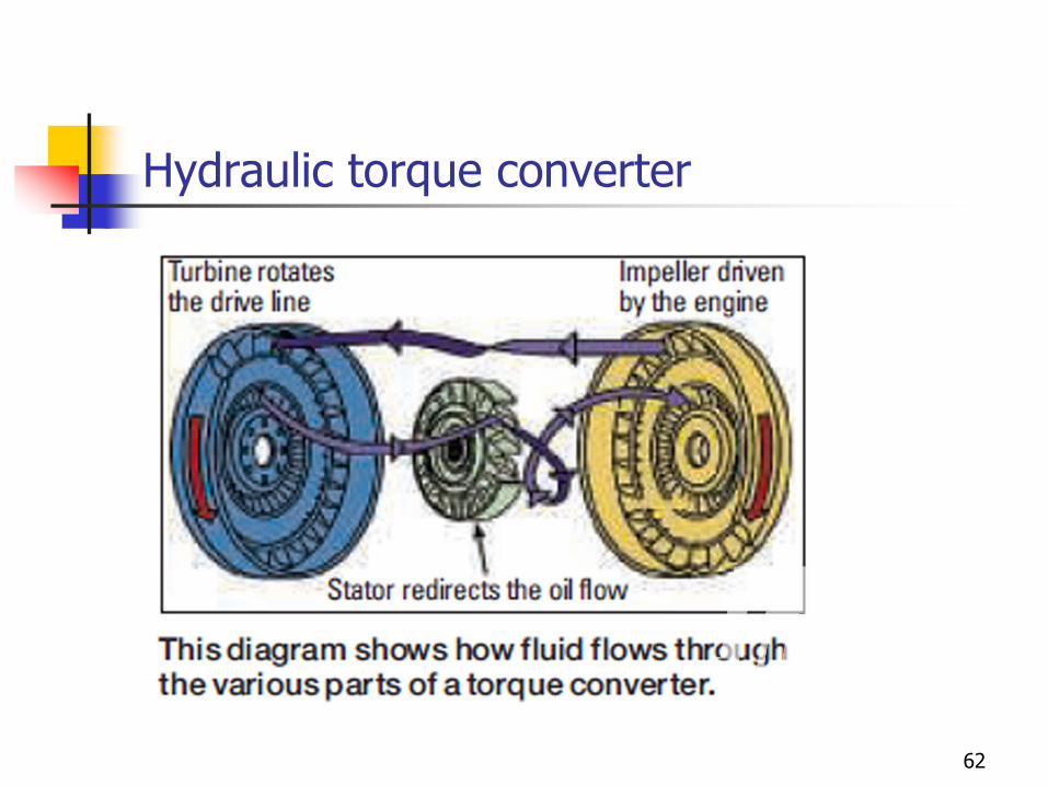
Hydraulic torque converter
62
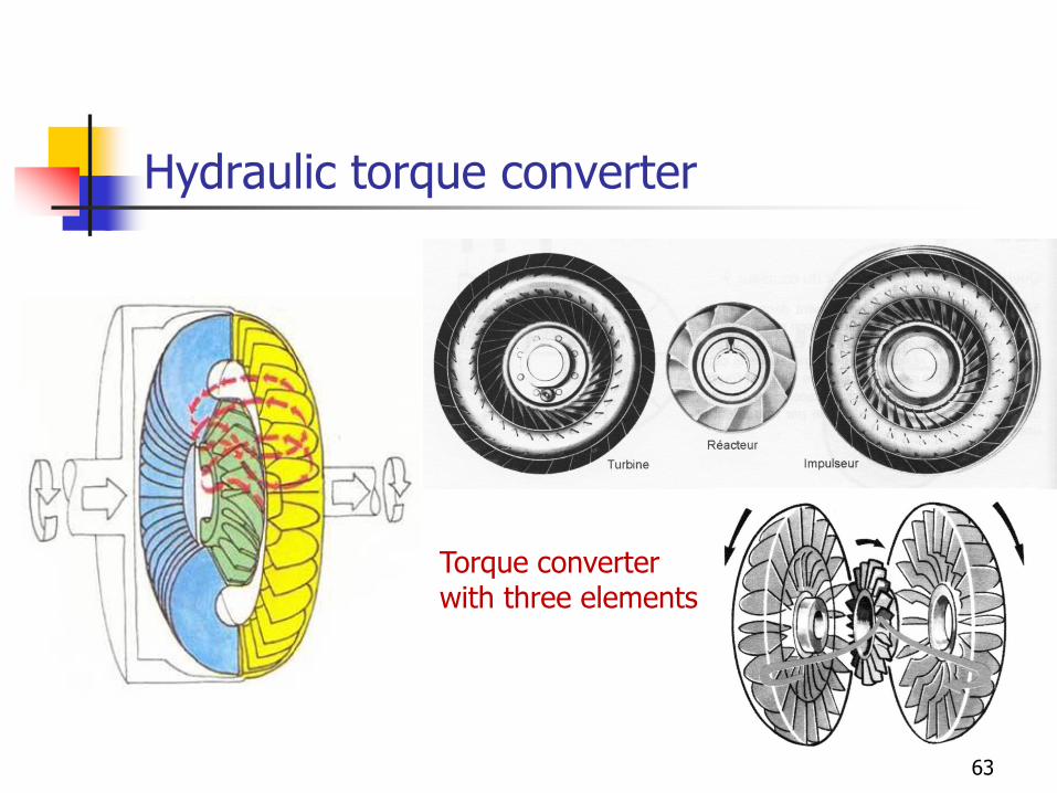
Hydraulic torque converter
Torque converter with three elements
63
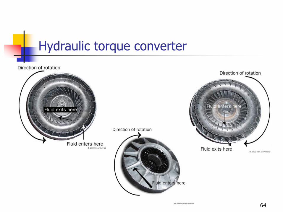
Hydraulic torque converter
64
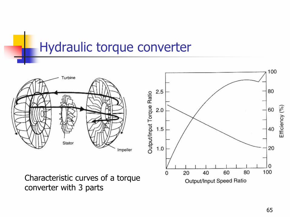
Hydraulic torque converter
Characteristic curves of a torque converter with 3 parts
65
Hydraulic torque converter
◼ Advantages:
◼ Simplicity of the working principle
◼ Suppression of the clutch pedal
◼ Higher progressivity compared to dry friction clutches
◼ Magnification of the torque for high load torques and low rotation speed of the output shaft
◼ Longer lifetime
◼ Drawbacks:
◼ Lower efficiency because of the presence of a velocity slip even when closed. Zero efficiency when the output shaft experiences high slip
◼ Irreversible character: no torque transmitted when the output shaft spins in the reverse way. So no engine brake is possible
◼ Higher weight
66
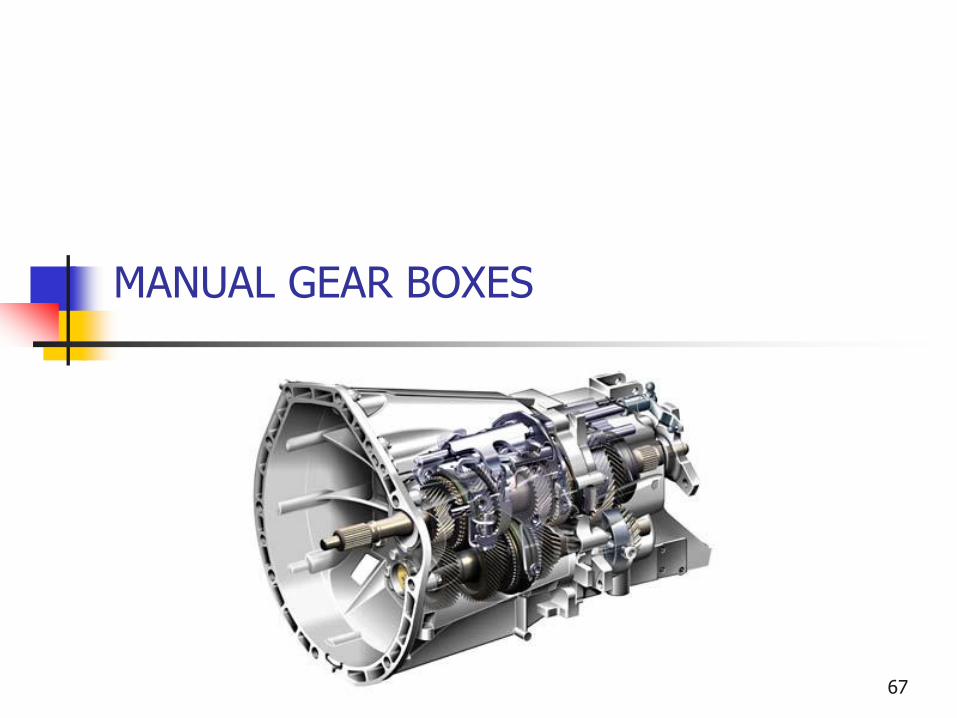
MANUAL GEAR BOXES
67
GEAR BOXES
◼ Adapt the rotation speed and the torque to driving conditions
◼ To be able to deliver the maximum power of the power plant whatever be the driving speed
◼ To be able to match the operating range of ICE with the range of the wheel rotation speeds during driving from rest to maximum speed
◼ Idle regime
◼ Maximum speed regime
◼ The gear box is not the sole element to introduce a reduction ratio. The differential generally provides a fixed (final) gear ratio. This reduces the size and the weight of the gear box.
◼ The gear box is often the only component to have a variable gear ratio
68
GEAR BOXES
69
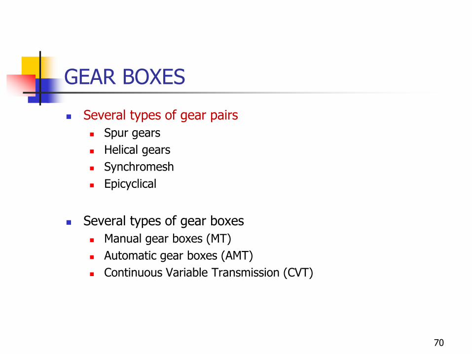
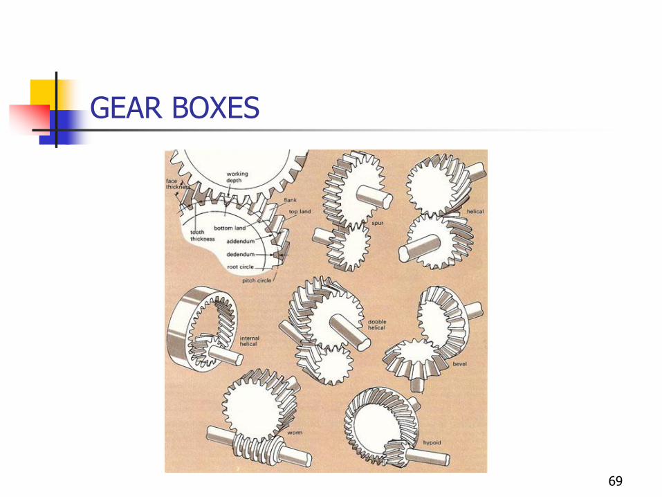
GEAR BOXES
◼ Several types of gear pairs
◼ Spur gears
◼ Helical gears
◼ Synchromesh
◼ Epicyclical
◼ Several types of gear boxes
◼ Manual gear boxes (MT)
◼ Automatic gear boxes (AMT)
◼ Continuous Variable Transmission (CVT)
70
MANUAL GEAR BOXES
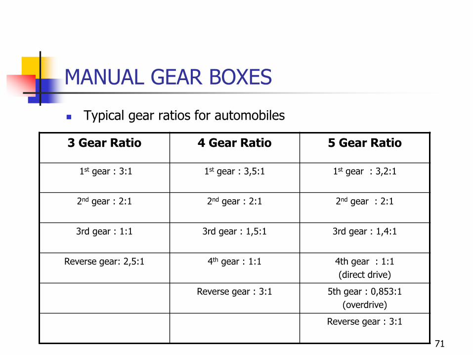
◼ Typical gear ratios for automobiles
3 Gear Ratio 4 Gear Ratio 5 Gear Ratio
1st gear : 3:1 1st gear : 3,5:1 1st gear : 3,2:1
2nd gear : 2:1 2nd gear : 2:1 2nd gear : 2:1
3rd gear : 1:1 3rd gear : 1,5:1 3rd gear : 1,4:1
Reverse gear: 2,5:1 4th gear : 1:1 4th gear : 1:1
(direct drive)
Reverse gear : 3:1 5th gear : 0,853:1
(overdrive)
Reverse gear : 3:1
71
MANUAL GEAR BOXES
72
MANUAL GEAR BOXES
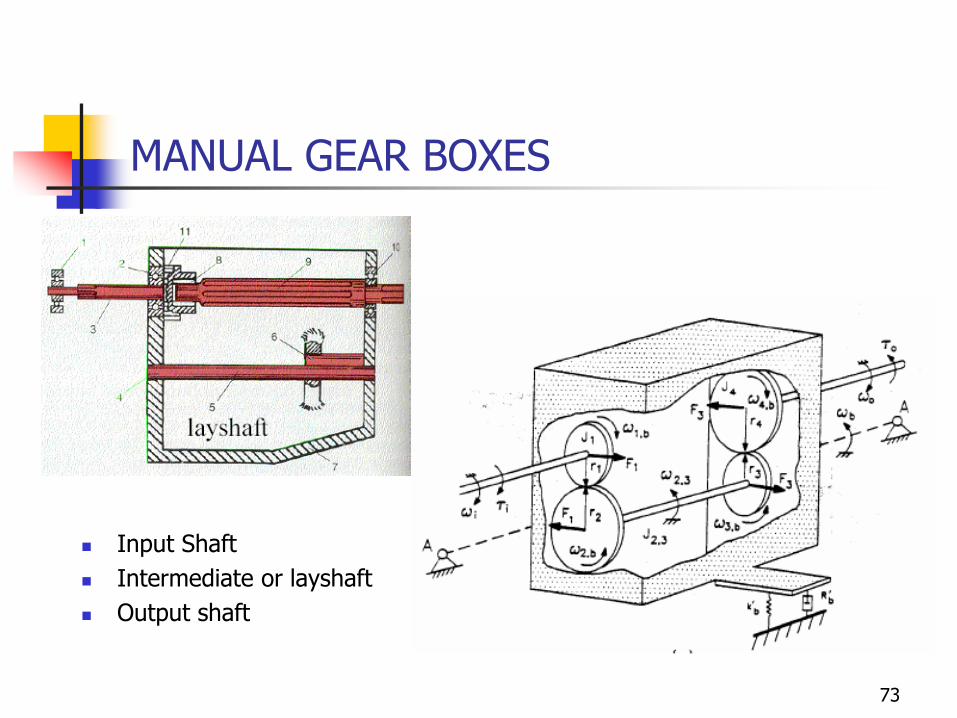
◼ Input Shaft
◼ Intermediate or layshaft
◼ Output shaft
73
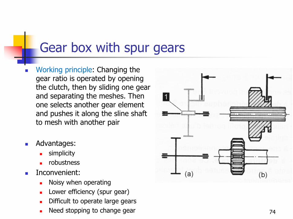
Gear box with spur gears
◼ Working principle: Changing the gear ratio is operated by opening the clutch, then by sliding one gear and separating the meshes. Then one selects another gear element and pushes it along the sline shaft to mesh with another pair
◼ Advantages:
◼ simplicity
◼ robustness
◼ Inconvenient:
◼ Noisy when operating
◼ Lower efficiency (spur gear)
◼ Difficult to operate large gears
◼ Need stopping to change gear 74
Helical gear boxes
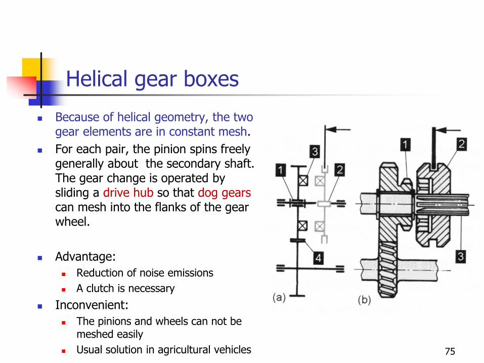
◼ Because of helical geometry, the two gear elements are in constant mesh.
◼ For each pair, the pinion spins freely generally about the secondary shaft. The gear change is operated by sliding a drive hub so that dog gears can mesh into the flanks of the gear wheel.
◼ Advantage:
◼ Reduction of noise emissions
◼ A clutch is necessary
◼ Inconvenient:
◼ The pinions and wheels can not be meshed easily
◼ Usual solution in agricultural vehicles 75
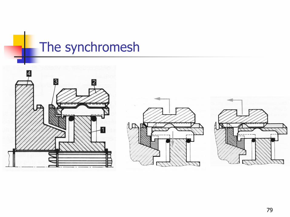
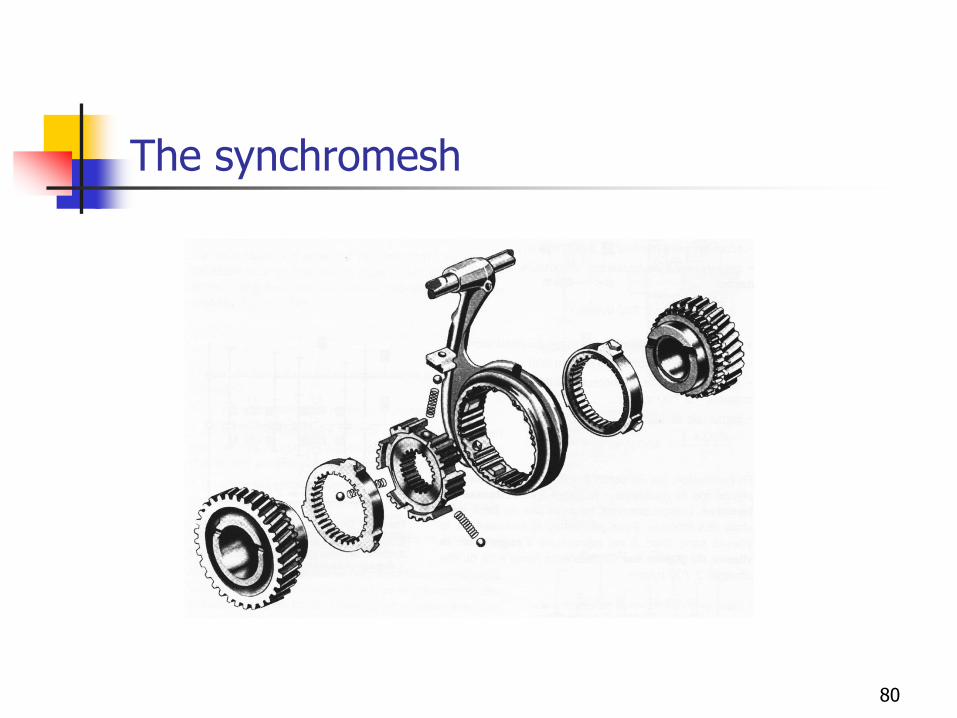
The synchromesh
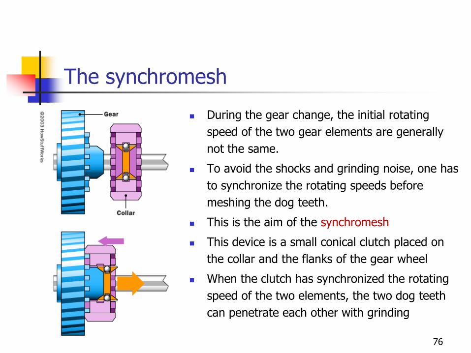
◼ During the gear change, the initial rotating
speed of the two gear elements are generally
not the same.
◼ To avoid the shocks and grinding noise, one has
to synchronize the rotating speeds before
meshing the dog teeth.
◼ This is the aim of the synchromesh
◼ This device is a small conical clutch placed on
the collar and the flanks of the gear wheel
◼ When the clutch has synchronized the rotating
speed of the two elements, the two dog teeth
can penetrate each other with grinding
76
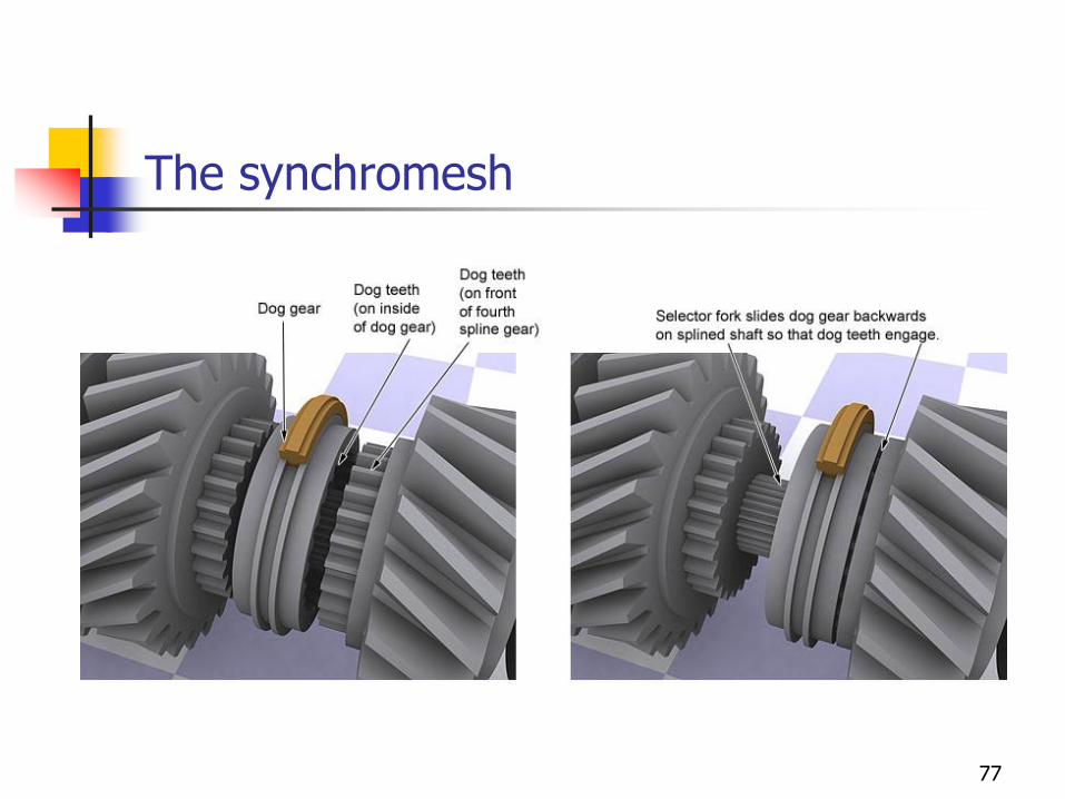
The synchromesh
77
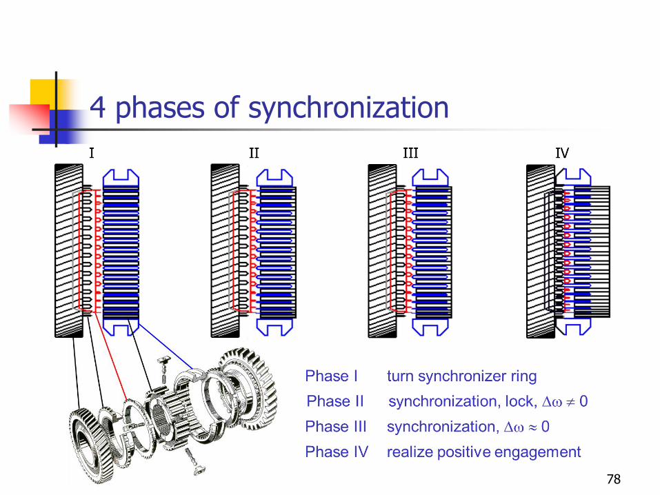
4 phases of synchronization
78
The synchromesh
79
The synchromesh
80
The synchromesh
81
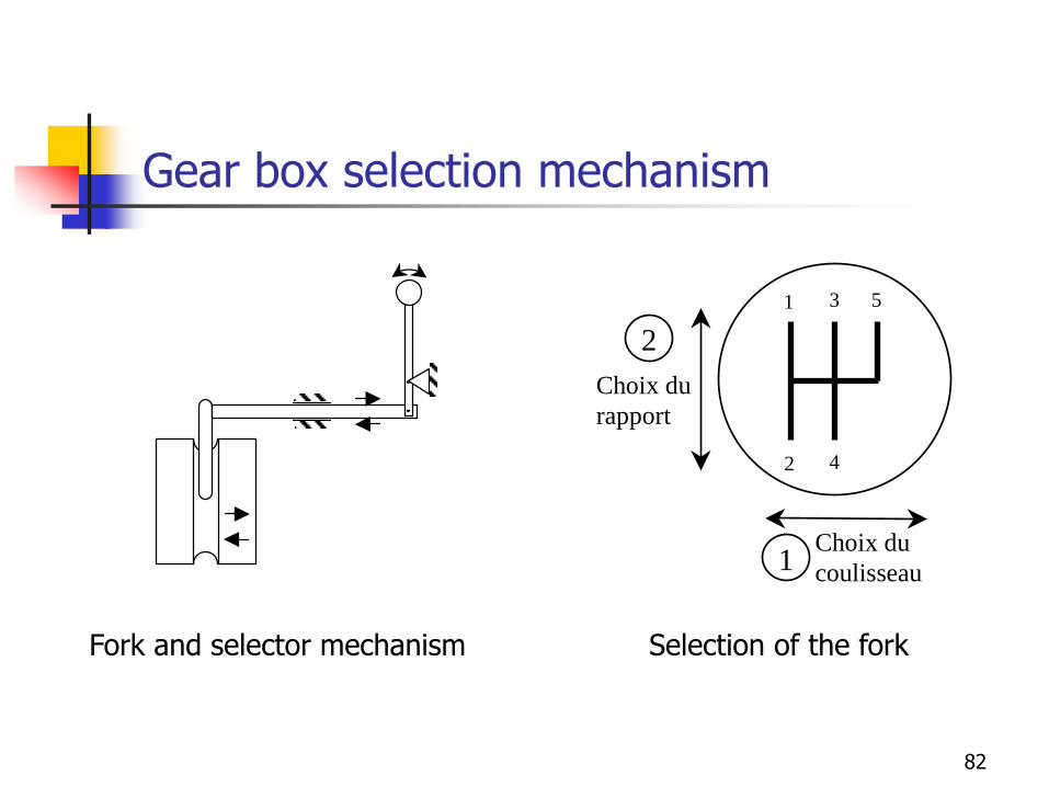
Gear box selection mechanism
Fork and selector mechanism
1 3
4
5
2
Choix du
coulisseau
Choix du
rapport
1
2
Selection of the fork
82
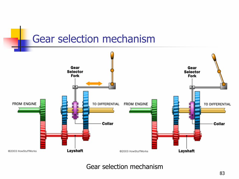
Gear selection mechanism
Gear selection mechanism83
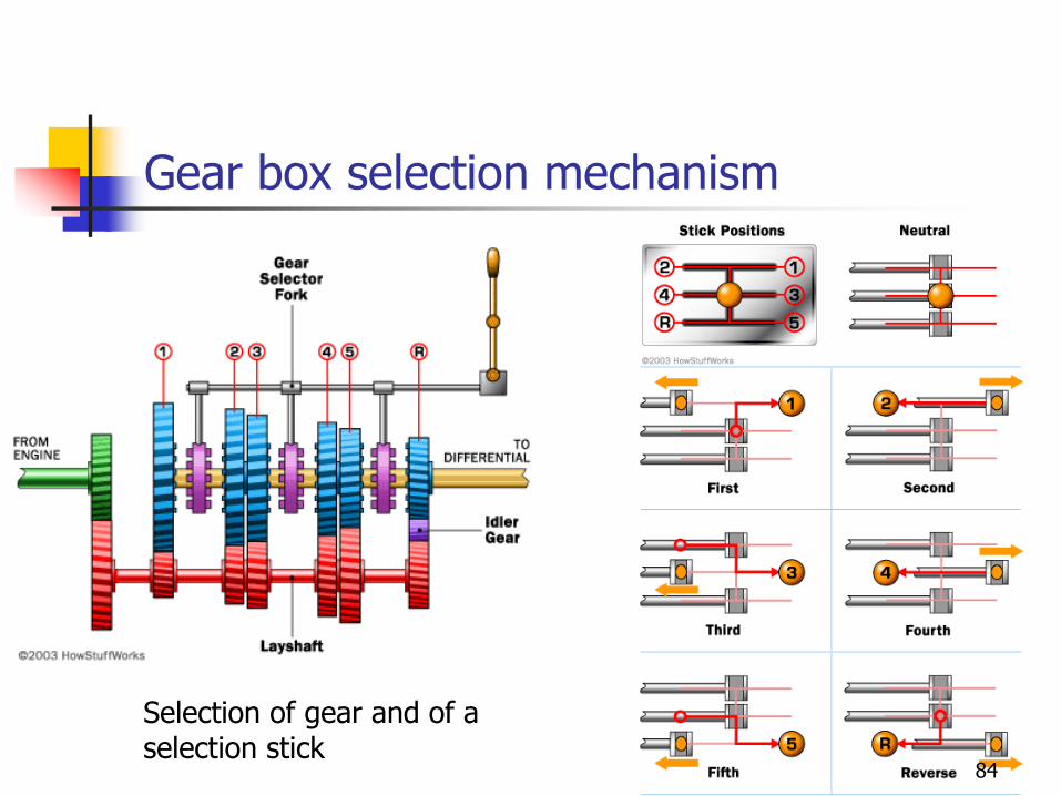
Gear box selection mechanism
Selection of gear and of a selection stick
84
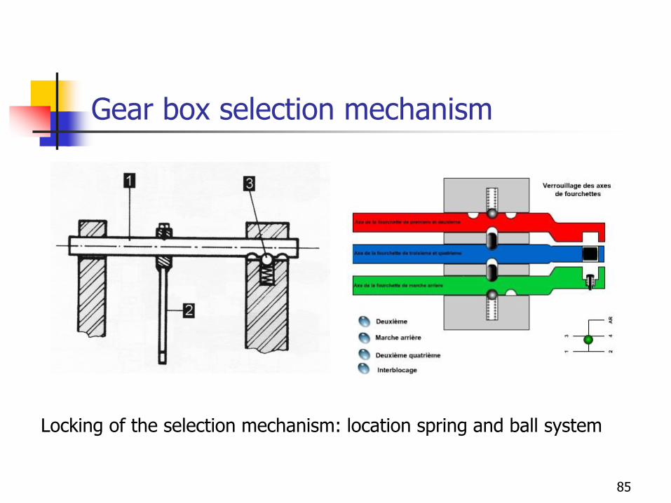
Gear box selection mechanism
Locking of the selection mechanism: location spring and ball system
85
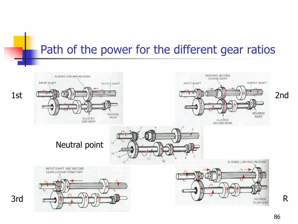
Path of the power for the different gear ratios
Neutral point
1st 2nd
3rd R
86
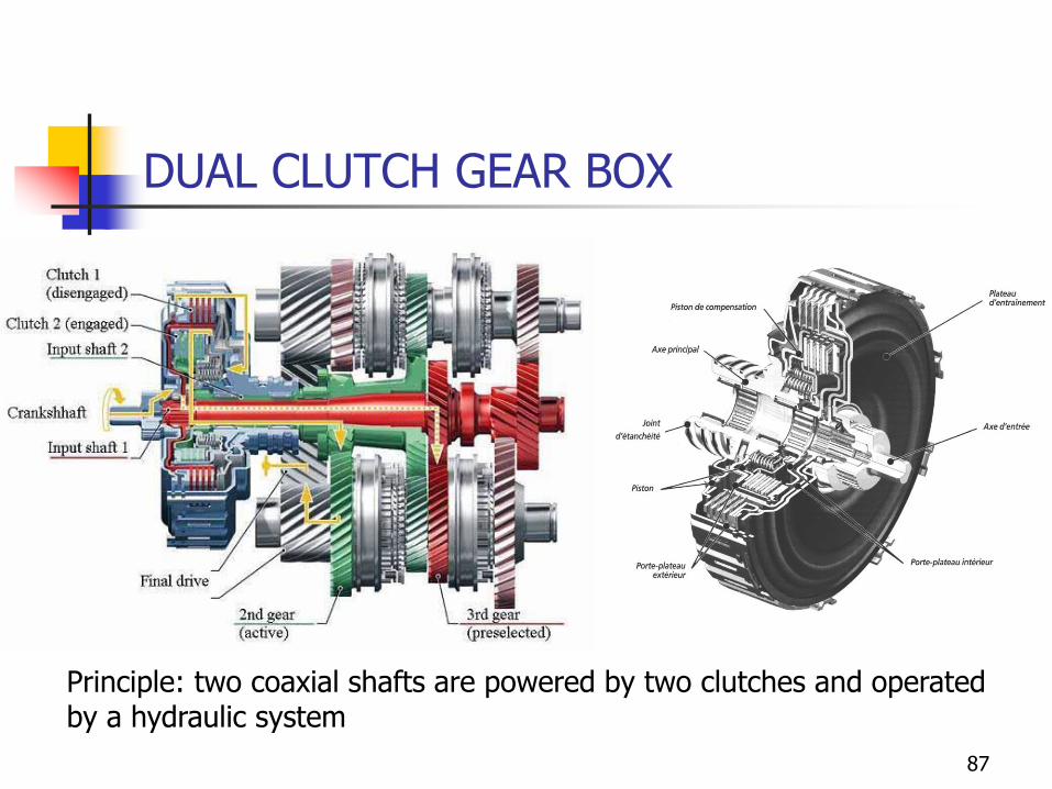
DUAL CLUTCH GEAR BOX
Principle: two coaxial shafts are powered by two clutches and operated by a hydraulic system
87
GEAR RATIO SELECTION
◼ The choice of the gear ratios is realized on the following bases:
◼ The highest ratio is calculated to match the maximum speed of the vehicle
◼ The first gear ratio is based on the maximum gradeability and on the drawbar pull specifications
◼ The selection of the intermediate gear ratios are made following a strategy
◼ Geometric distribution
◼ Fuel consumption minimization
88
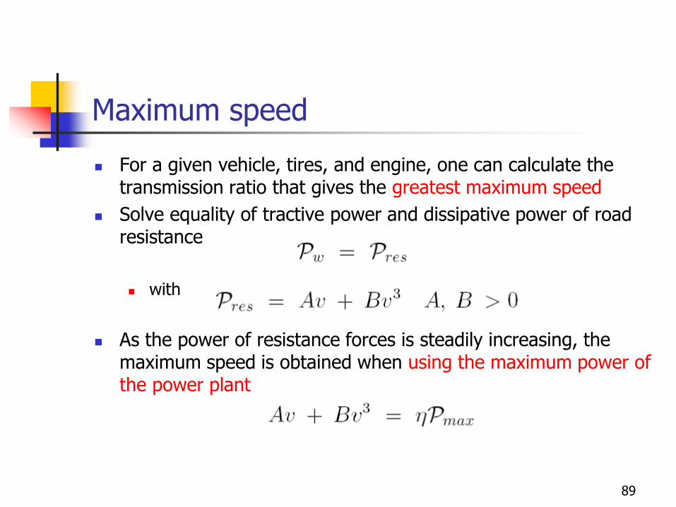
Maximum speed
◼ For a given vehicle, tires, and engine, one can calculate the transmission ratio that gives the greatest maximum speed
◼ Solve equality of tractive power and dissipative power of road resistance
◼ with
◼ As the power of resistance forces is steadily increasing, the maximum speed is obtained when using the maximum power of the power plant
89
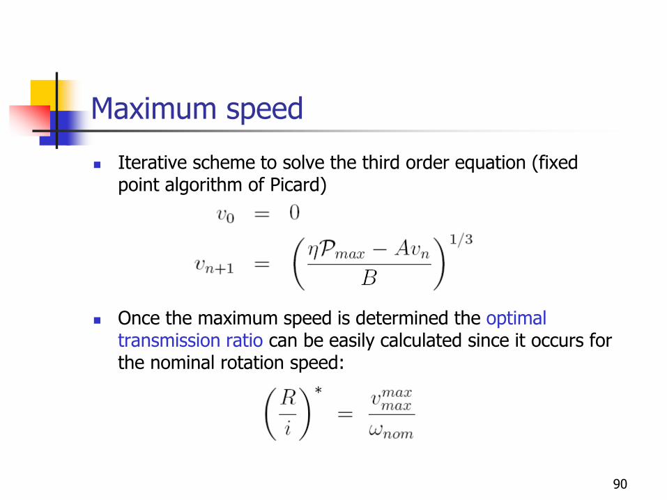
Maximum speed
◼ Iterative scheme to solve the third order equation (fixed point algorithm of Picard)
◼ Once the maximum speed is determined the optimal transmission ratio can be easily calculated since it occurs for the nominal rotation speed:
90
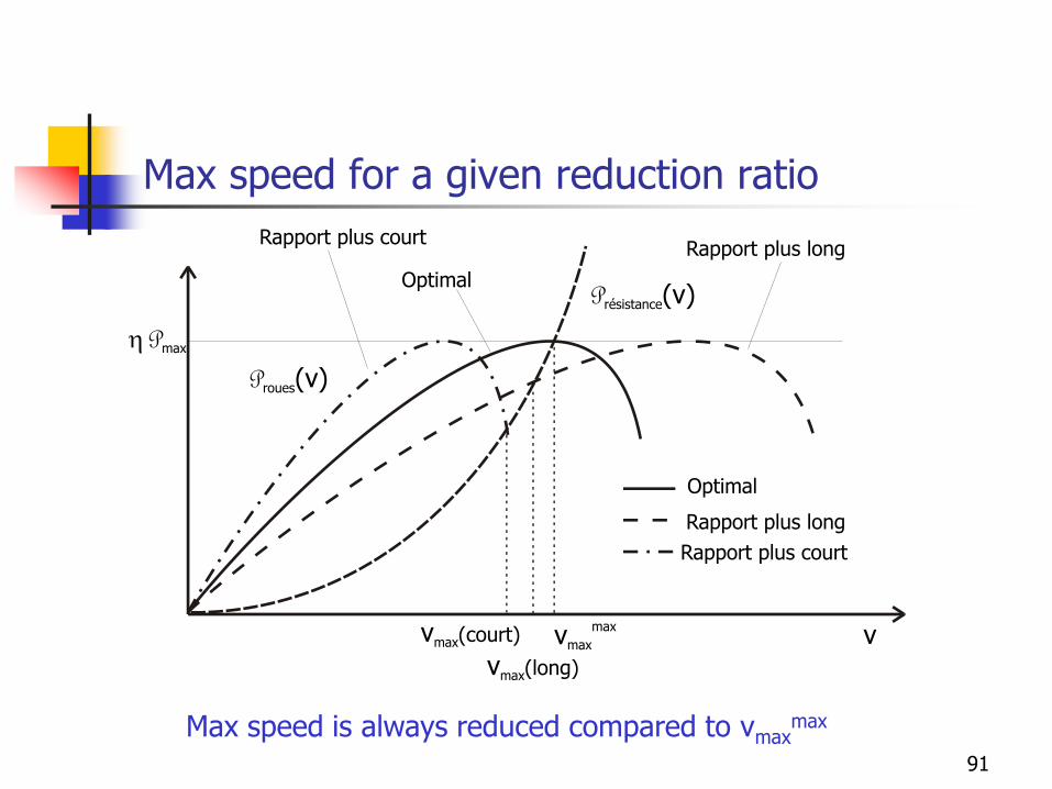
Max speed for a given reduction ratio
Proues(v)
v
h Pmax
vmax(long)
Présistance(v)
Rapport plus long
Optimal
Rapport plus court
vmax
maxvmax(court)
Rapport plus court
Optimal
Rapport plus long
Max speed is always reduced compared to vmaxmax
91
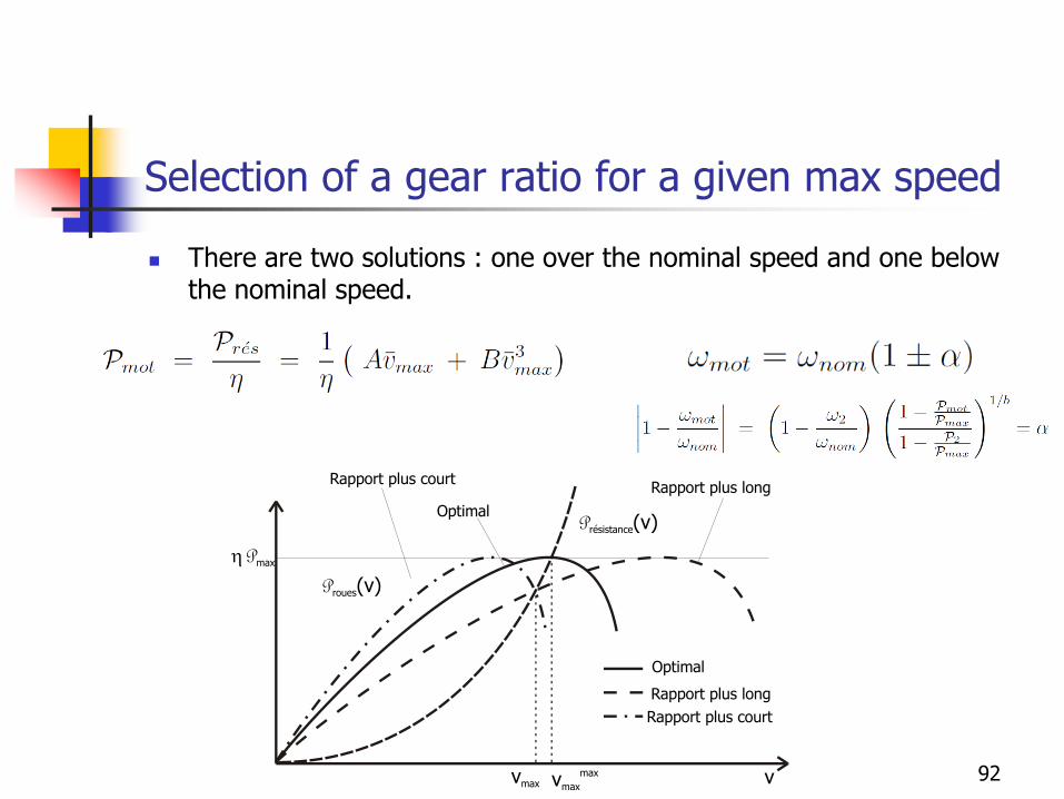
Selection of a gear ratio for a given max speed
◼ There are two solutions : one over the nominal speed and one below the nominal speed.
Proues(v)
v
h Pmax
Présistance(v)
Rapport plus long
Optimal
Rapport plus court
vmax
maxvmax
Rapport plus court
Optimal
Rapport plus long
92
Selection of the final gear ratio
◼ Design specifications related to the maximum speed (from Wong)
◼ To be able to drive at the maximum speed with the given engine
◼ To be able to keep a constant speed between 88 and 96 kph while climbing a slope of at least 3% on the final gear ratio
◼ These specifications enable to calculate the final gear ratio
◼ The specification about the maximum speed gives a final gear ratio
◼ If two choices are possible, one will choose the gear ratio that is a bit above the nominal speed in order to keep a certain power reserve against the ageing or the engine, gust winds, etc.
93
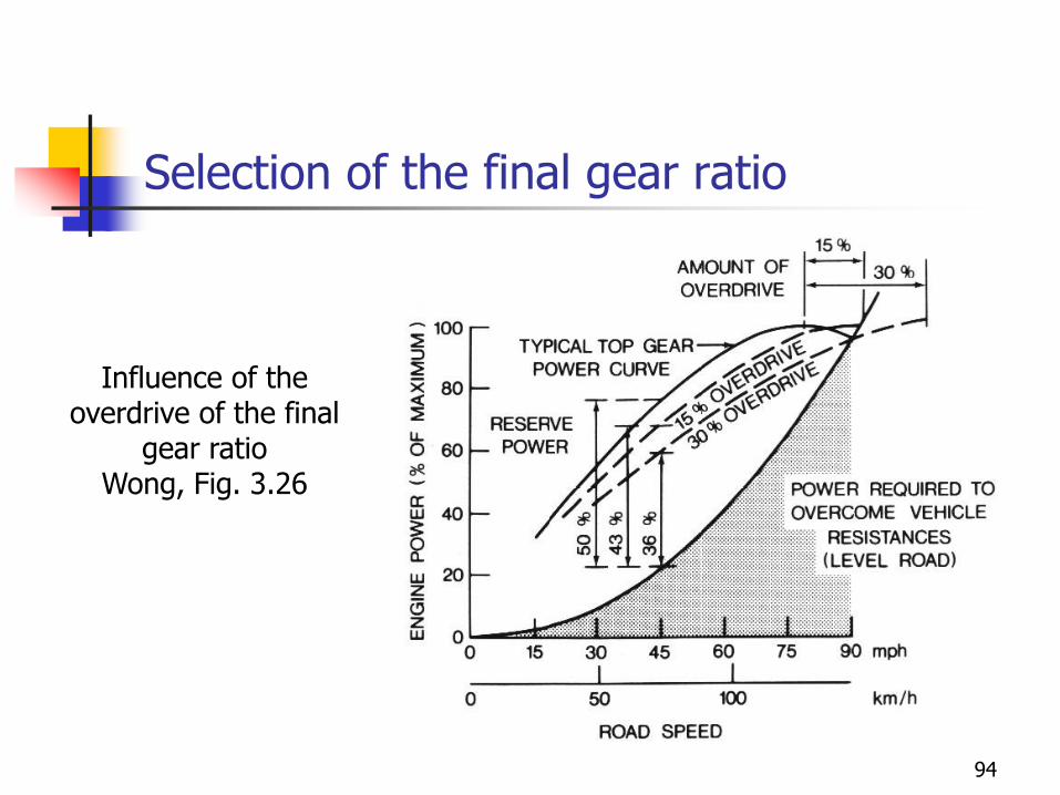
Selection of the final gear ratio
Influence of the overdrive of the final
gear ratio Wong, Fig. 3.26
94
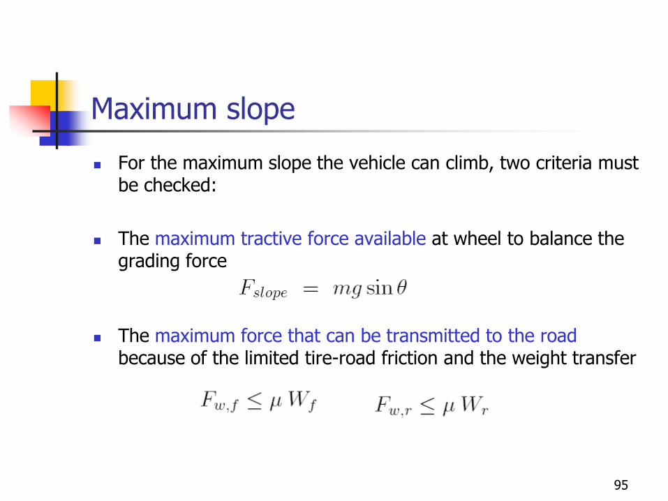
Maximum slope
◼ For the maximum slope the vehicle can climb, two criteria must be checked:
◼ The maximum tractive force available at wheel to balance the grading force
◼ The maximum force that can be transmitted to the roadbecause of the limited tire-road friction and the weight transfer
95
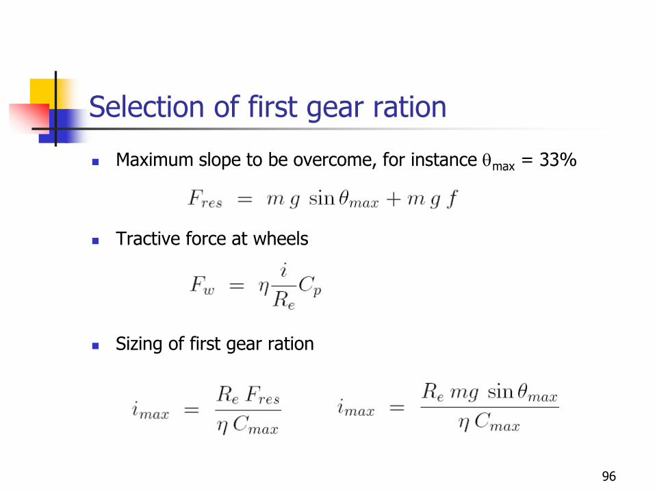
Selection of first gear ration
◼ Maximum slope to be overcome, for instance max = 33%
◼ Tractive force at wheels
◼ Sizing of first gear ration
96
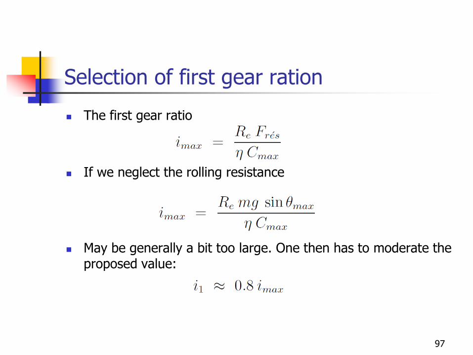
Selection of first gear ration
◼ The first gear ratio
◼ If we neglect the rolling resistance
◼ May be generally a bit too large. One then has to moderate the proposed value:
97
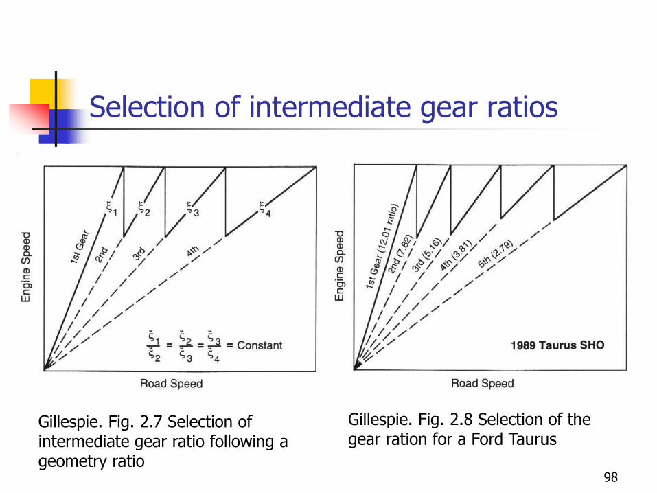
Selection of intermediate gear ratios
Gillespie. Fig. 2.7 Selection of intermediate gear ratio following a geometry ratio
Gillespie. Fig. 2.8 Selection of the gear ration for a Ford Taurus
98
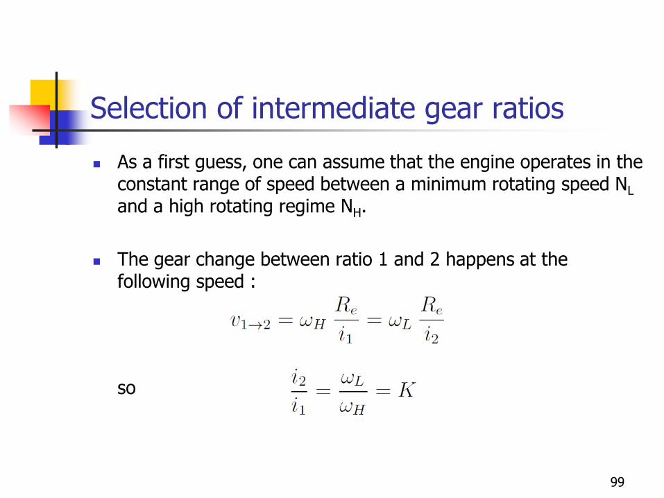
Selection of intermediate gear ratios
◼ As a first guess, one can assume that the engine operates in the constant range of speed between a minimum rotating speed NL
and a high rotating regime NH.
◼ The gear change between ratio 1 and 2 happens at the following speed :
so
99
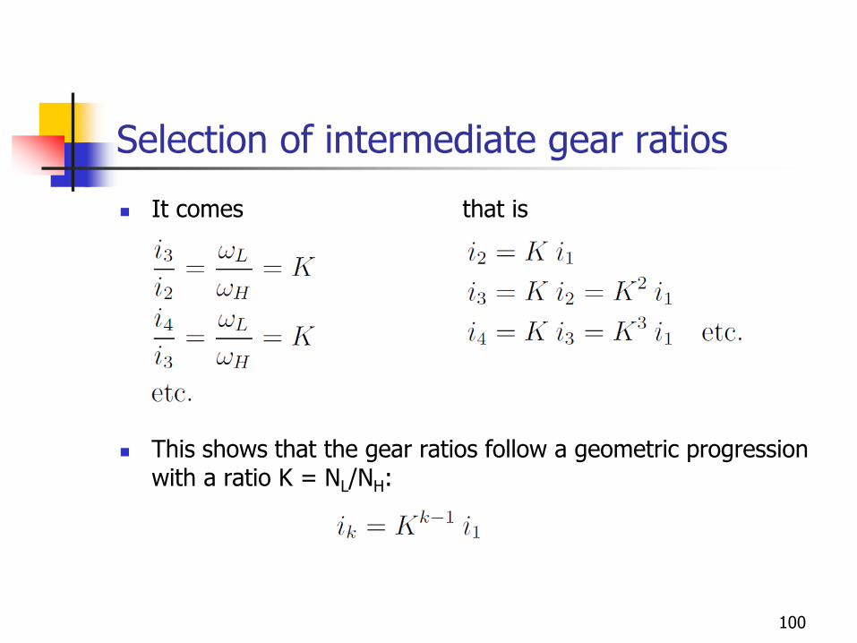
Selection of intermediate gear ratios
◼ It comes that is
◼ This shows that the gear ratios follow a geometric progression with a ratio K = NL/NH:
100
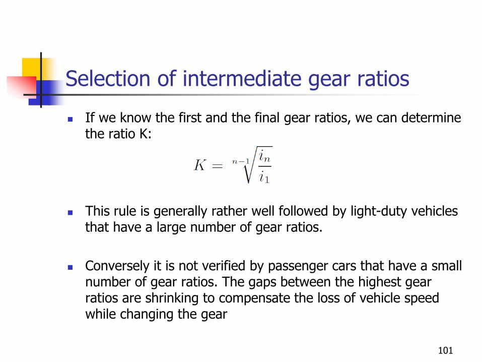
Selection of intermediate gear ratios
◼ If we know the first and the final gear ratios, we can determine the ratio K:
◼ This rule is generally rather well followed by light-duty vehicles that have a large number of gear ratios.
◼ Conversely it is not verified by passenger cars that have a small number of gear ratios. The gaps between the highest gear ratios are shrinking to compensate the loss of vehicle speed while changing the gear
101
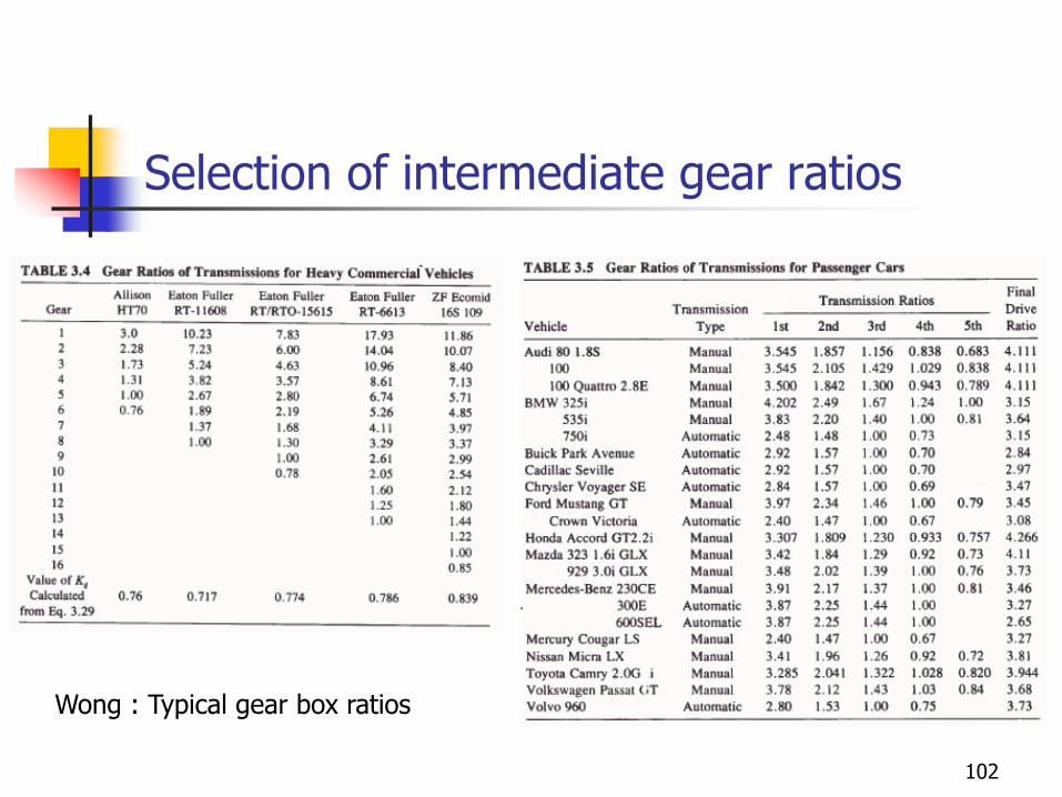
Selection of intermediate gear ratios
Wong : Typical gear box ratios
102
Selection of intermediate gear ratios
◼ However nowadays, the selection of the gear ratios has become a very complex problems because of its strong impact on fuel consumption and emissions, because of the driving comfort.
103
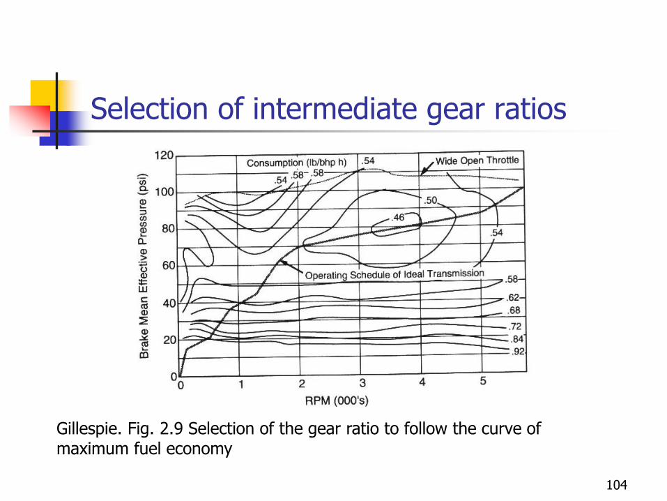
Selection of intermediate gear ratios
Gillespie. Fig. 2.9 Selection of the gear ratio to follow the curve of maximum fuel economy
104