measuring irrigation flow
TRANSCRIPT
1 LSU AgCenter Pub. 3241-L: Measuring Irrigation Flow
Measuring Irrigation FlowRon E. Sheffield, Biological and Agricultural Engineering, LSU AgCenter
Christopher G. Henry, Biological and Agricultural Engineering, University of Arkansas David Bankston, Food Sciences, LSU AgCenter
William A. Hadden, Extension Specialist (retired), LSU AgCenter
Measuring irrigation flow contributes to better management and scheduling of irrigation events, thus improving profitability.
Such measurements are needed to evaluate the performance of an irrigation pumping plant. Irrigation flow measurements also are a tool for quantifying irrigation water use and are useful in evaluating the effects of management changes or conservation measures.
This publication will help irrigators learn to select, install and use irrigation flow meters, as well as estimate flow manually using simple hydraulic formulas. In almost all cases, for flow meters to be accurate, pipes must be full of water (full pipe flow).
Propeller Flow MetersPropeller flow meters are the most
common devices used for measuring water flow rate and totalization (Figure 1). The accuracy standard of plus or minus 2 percent for water propeller meters is set by the American Water Works Association Standard No. C704-12.
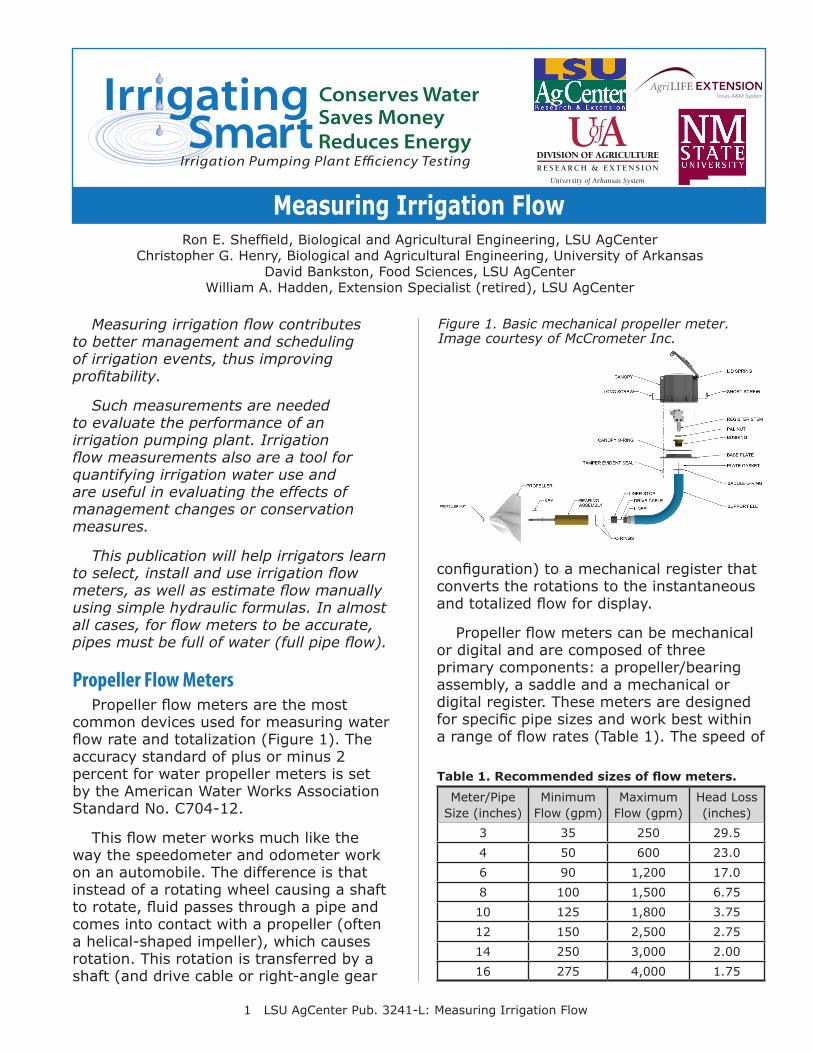
This flow meter works much like the way the speedometer and odometer work on an automobile. The difference is that instead of a rotating wheel causing a shaft to rotate, fluid passes through a pipe and comes into contact with a propeller (often a helical-shaped impeller), which causes rotation. This rotation is transferred by a shaft (and drive cable or right-angle gear
configuration) to a mechanical register that converts the rotations to the instantaneous and totalized flow for display.
Propeller flow meters can be mechanical or digital and are composed of three primary components: a propeller/bearing assembly, a saddle and a mechanical or digital register. These meters are designed for specific pipe sizes and work best within a range of flow rates (Table 1). The speed of
Figure 1. Basic mechanical propeller meter. Image courtesy of McCrometer Inc.
Table 1. Recommended sizes of flow meters.
Meter/Pipe Size (inches)
MinimumFlow (gpm)
Maximum Flow (gpm)
Head Loss(inches)
3 35 250 29.54 50 600 23.06 90 1,200 17.08 100 1,500 6.7510 125 1,800 3.7512 150 2,500 2.7514 250 3,000 2.0016 275 4,000 1.75
2 LSU AgCenter Pub. 3241-L: Measuring Irrigation Flow
the propeller is a function of the flow rate. The register accumulates the number of turns of the propeller and converts this to the flow rate or volume of water passing the propeller.
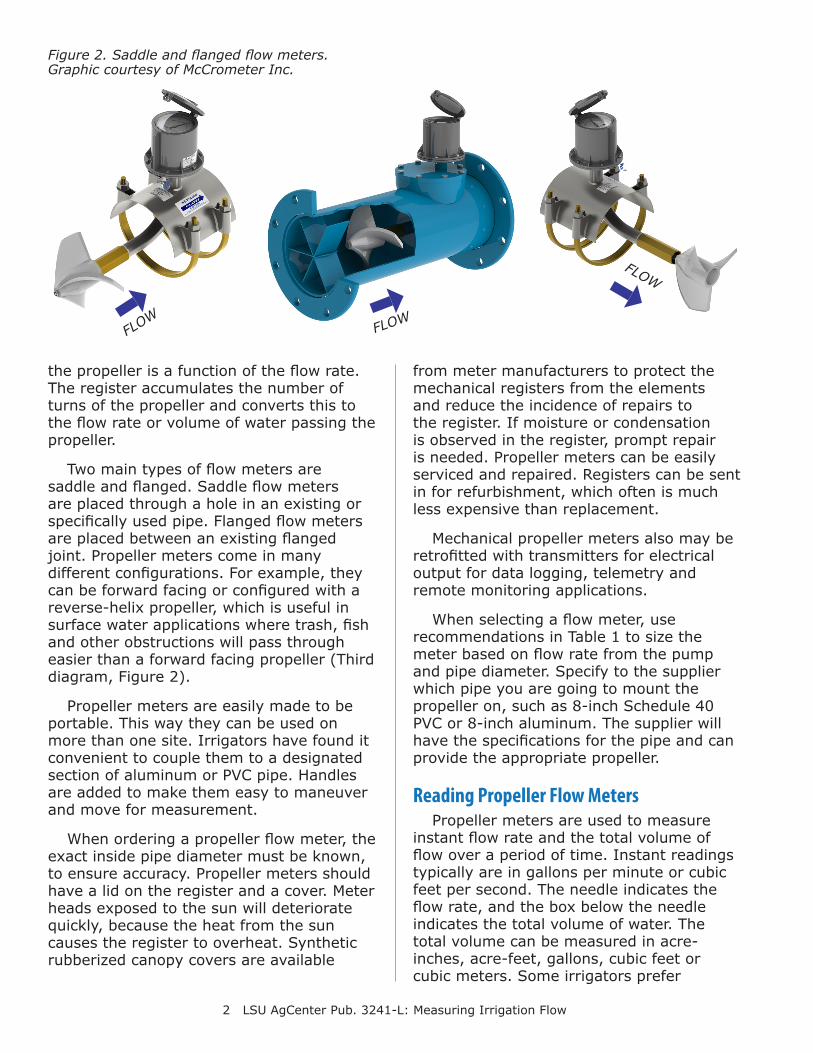
Two main types of flow meters are saddle and flanged. Saddle flow meters are placed through a hole in an existing or specifically used pipe. Flanged flow meters are placed between an existing flanged joint. Propeller meters come in many different configurations. For example, they can be forward facing or configured with a reverse-helix propeller, which is useful in surface water applications where trash, fish and other obstructions will pass through easier than a forward facing propeller (Third diagram, Figure 2).
Propeller meters are easily made to be portable. This way they can be used on more than one site. Irrigators have found it convenient to couple them to a designated section of aluminum or PVC pipe. Handles are added to make them easy to maneuver and move for measurement.
When ordering a propeller flow meter, the exact inside pipe diameter must be known, to ensure accuracy. Propeller meters should have a lid on the register and a cover. Meter heads exposed to the sun will deteriorate quickly, because the heat from the sun causes the register to overheat. Synthetic rubberized canopy covers are available
Figure 2. Saddle and flanged flow meters. Graphic courtesy of McCrometer Inc.
FLOW
FLOW
FLOW
from meter manufacturers to protect the mechanical registers from the elements and reduce the incidence of repairs to the register. If moisture or condensation is observed in the register, prompt repair is needed. Propeller meters can be easily serviced and repaired. Registers can be sent in for refurbishment, which often is much less expensive than replacement.
Mechanical propeller meters also may be retrofitted with transmitters for electrical output for data logging, telemetry and remote monitoring applications.
When selecting a flow meter, use recommendations in Table 1 to size the meter based on flow rate from the pump and pipe diameter. Specify to the supplier which pipe you are going to mount the propeller on, such as 8-inch Schedule 40 PVC or 8-inch aluminum. The supplier will have the specifications for the pipe and can provide the appropriate propeller.
Reading Propeller Flow MetersPropeller meters are used to measure
instant flow rate and the total volume of flow over a period of time. Instant readings typically are in gallons per minute or cubic feet per second. The needle indicates the flow rate, and the box below the needle indicates the total volume of water. The total volume can be measured in acre-inches, acre-feet, gallons, cubic feet or cubic meters. Some irrigators prefer
3 LSU AgCenter Pub. 3241-L: Measuring Irrigation Flow
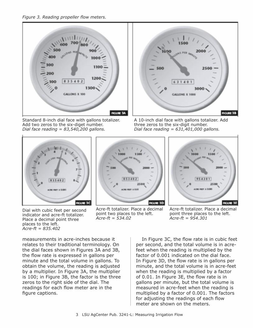
measurements in acre-inches because it relates to their traditional terminology. On the dial faces shown in Figures 3A and 3B, the flow rate is expressed in gallons per minute and the total volume in gallons. To obtain the volume, the reading is adjusted by a multiplier. In Figure 3A, the multiplier is 100; in Figure 3B, the factor is the three zeros to the right side of the dial. The readings for each flow meter are in the figure captions.
In Figure 3C, the flow rate is in cubic feet per second, and the total volume is in acre-feet when the reading is multiplied by the factor of 0.001 indicated on the dial face. In Figure 3D, the flow rate is in gallons per minute, and the total volume is in acre-feet when the reading is multiplied by a factor of 0.01. In Figure 3E, the flow rate is in gallons per minute, but the total volume is measured in acre-feet when the reading is multiplied by a factor of 0.001. The factors for adjusting the readings of each flow meter are shown on the meters.
Standard 8-inch dial face with gallons totalizer. Add two zeros to the six-diget number.Dial face reading = 83,540,200 gallons.
A 10-inch dial face with gallons totalizer. Add three zeros to the six-digit number.Dial face reading = 631,401,000 gallons.
Dial with cubic feet per second indicator and acre-ft totalizer. Place a decimal point three places to the left.Acre-ft = 835.402
Acre-ft totalizer. Place a decimal point two places to the left.Acre-ft = 534.02
Acre-ft totalizer. Place a decimal point three places to the left.Acre-ft = 954.301
Figure 3. Reading propeller flow meters.
4 LSU AgCenter Pub. 3241-L: Measuring Irrigation Flow
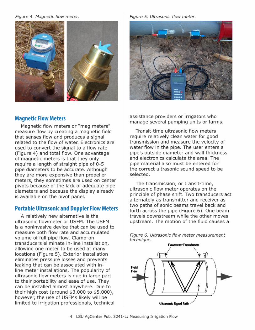
Magnetic Flow MetersMagnetic flow meters or “mag meters”
measure flow by creating a magnetic field that senses flow and produces a signal related to the flow of water. Electronics are used to convert the signal to a flow rate (Figure 4) and total flow. One advantage of magnetic meters is that they only require a length of straight pipe of 0-5 pipe diameters to be accurate. Although they are more expensive than propeller meters, they sometimes are used on center pivots because of the lack of adequate pipe diameters and because the display already is available on the pivot panel.
Portable Ultrasonic and Doppler Flow MetersA relatively new alternative is the
ultrasonic flowmeter or USFM. The USFM is a noninvasive device that can be used to measure both flow rate and accumulated volume of full pipe flow. Clamp-on transducers eliminate in-line installation, allowing one meter to be used at many locations (Figure 5). Exterior installation eliminates pressure losses and prevents leaking that can be associated with in-line meter installations. The popularity of ultrasonic flow meters is due in large part to their portability and ease of use. They can be installed almost anywhere. Due to their high cost (around $3,000 to $5,000), however, the use of USFMs likely will be limited to irrigation professionals, technical
assistance providers or irrigators who manage several pumping units or farms.
Transit-time ultrasonic flow meters require relatively clean water for good transmission and measure the velocity of water flow in the pipe. The user enters a pipe’s outside diameter and wall thickness and electronics calculate the area. The pipe material also must be entered for the correct ultrasonic sound speed to be selected.
The transmission, or transit-time, ultrasonic flow meter operates on the principle of phase shift. Two transducers act alternately as transmitter and receiver as two paths of sonic beams travel back and forth across the pipe (Figure 6). One beam travels downstream while the other moves upstream. The motion of the fluid causes a
Figure 4. Magnetic flow meter. Figure 5. Ultrasonic flow meter.
Figure 6. Ultrasonic flow meter measurement technique.
5 LSU AgCenter Pub. 3241-L: Measuring Irrigation Flow
frequency shift in both waves. This shift is related to the velocity of the fluid. Research has shown that, when installed properly, USFM accuracy ranges from plus or minus 1 percent to plus or minus 5 percent of full scale.
Doppler flow meters are less common and operate similarly to ultrasonic flow meters, although these meters use Doppler waves to measure the velocity of particles in the water. For Doppler flow meters to work accurately, the water cannot be perfectly clean (so these possibly are a solution where an ultrasonic flow meter cannot measure flow because the water is too “dirty”).
Installing Flow MetersWhen measuring fluid flow in a pipeline,
proper flow meter installation is one of the most important requirements for accurate flow measurement. This is true for any type of meter – propeller, magnetic, insertion, ultrasonic or other type.
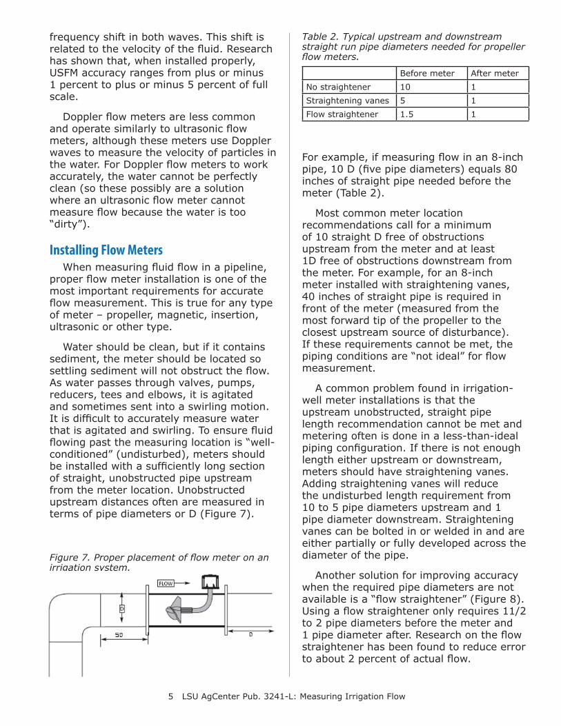
Water should be clean, but if it contains sediment, the meter should be located so settling sediment will not obstruct the flow. As water passes through valves, pumps, reducers, tees and elbows, it is agitated and sometimes sent into a swirling motion. It is difficult to accurately measure water that is agitated and swirling. To ensure fluid flowing past the measuring location is “well-conditioned” (undisturbed), meters should be installed with a sufficiently long section of straight, unobstructed pipe upstream from the meter location. Unobstructed upstream distances often are measured in terms of pipe diameters or D (Figure 7).
For example, if measuring flow in an 8-inch pipe, 10 D (five pipe diameters) equals 80 inches of straight pipe needed before the meter (Table 2).
Most common meter location recommendations call for a minimum of 10 straight D free of obstructions upstream from the meter and at least 1D free of obstructions downstream from the meter. For example, for an 8-inch meter installed with straightening vanes, 40 inches of straight pipe is required in front of the meter (measured from the most forward tip of the propeller to the closest upstream source of disturbance). If these requirements cannot be met, the piping conditions are “not ideal” for flow measurement.
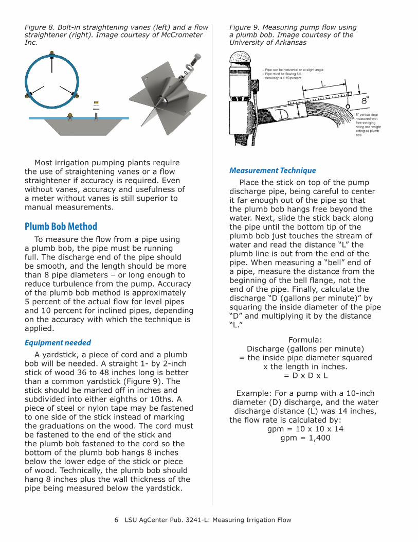
A common problem found in irrigation-well meter installations is that the upstream unobstructed, straight pipe length recommendation cannot be met and metering often is done in a less-than-ideal piping configuration. If there is not enough length either upstream or downstream, meters should have straightening vanes. Adding straightening vanes will reduce the undisturbed length requirement from 10 to 5 pipe diameters upstream and 1 pipe diameter downstream. Straightening vanes can be bolted in or welded in and are either partially or fully developed across the diameter of the pipe.
Another solution for improving accuracy when the required pipe diameters are not available is a “flow straightener” (Figure 8). Using a flow straightener only requires 11/2 to 2 pipe diameters before the meter and 1 pipe diameter after. Research on the flow straightener has been found to reduce error to about 2 percent of actual flow.
Before meter After meterNo straightener 10 1Straightening vanes 5 1Flow straightener 1.5 1
Table 2. Typical upstream and downstream straight run pipe diameters needed for propeller flow meters.
Figure 7. Proper placement of flow meter on an irrigation system.
6 LSU AgCenter Pub. 3241-L: Measuring Irrigation Flow
Most irrigation pumping plants require the use of straightening vanes or a flow straightener if accuracy is required. Even without vanes, accuracy and usefulness of a meter without vanes is still superior to manual measurements.
Plumb Bob MethodTo measure the flow from a pipe using
a plumb bob, the pipe must be running full. The discharge end of the pipe should be smooth, and the length should be more than 8 pipe diameters – or long enough to reduce turbulence from the pump. Accuracy of the plumb bob method is approximately 5 percent of the actual flow for level pipes and 10 percent for inclined pipes, depending on the accuracy with which the technique is applied.
Equipment neededA yardstick, a piece of cord and a plumb
bob will be needed. A straight 1- by 2-inch stick of wood 36 to 48 inches long is better than a common yardstick (Figure 9). The stick should be marked off in inches and subdivided into either eighths or 10ths. A piece of steel or nylon tape may be fastened to one side of the stick instead of marking the graduations on the wood. The cord must be fastened to the end of the stick and the plumb bob fastened to the cord so the bottom of the plumb bob hangs 8 inches below the lower edge of the stick or piece of wood. Technically, the plumb bob should hang 8 inches plus the wall thickness of the pipe being measured below the yardstick.
Figure 8. Bolt-in straightening vanes (left) and a flow straightener (right). Image courtesy of McCrometer Inc.
Figure 9. Measuring pump flow using a plumb bob. Image courtesy of the University of Arkansas
Measurement TechniquePlace the stick on top of the pump
discharge pipe, being careful to center it far enough out of the pipe so that the plumb bob hangs free beyond the water. Next, slide the stick back along the pipe until the bottom tip of the plumb bob just touches the stream of water and read the distance “L” the plumb line is out from the end of the pipe. When measuring a “bell” end of a pipe, measure the distance from the beginning of the bell flange, not the end of the pipe. Finally, calculate the discharge “D (gallons per minute)” by squaring the inside diameter of the pipe “D” and multiplying it by the distance “L.”
Formula: Discharge (gallons per minute)
= the inside pipe diameter squared x the length in inches.
= D x D x L
Example: For a pump with a 10-inch diameter (D) discharge, and the water discharge distance (L) was 14 inches,
the flow rate is calculated by: gpm = 10 x 10 x 14
gpm = 1,400
7 LSU AgCenter Pub. 3241-L: Measuring Irrigation Flow
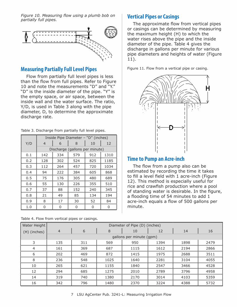
Measuring Partially Full Level PipesFlow from partially full level pipes is less
than the flow from full pipes. Refer to Figure 10 and note the measurements “D” and “Y.” “D” is the inside diameter of the pipe. “Y” is the empty space, or air space, between the inside wall and the water surface. The ratio, Y/D, is used in Table 3 along with the pipe diameter, D, to determine the approximate discharge rate.
Vertical Pipes or CasingsThe approximate flow from vertical pipes
or casings can be determined by measuring the maximum height (H) to which the water rises above the pipe and the inside diameter of the pipe. Table 4 gives the discharge in gallons per minute for various pipe diameters and heights of water (Figure 11).
Figure 10. Measuring flow using a plumb bob on partially full pipes.
Y/DInside Pipe Diameter – “D” (inches)
4 6 8 10 12Discharge (gallons per minute)
0.1 142 334 579 912 13100.2 128 302 524 825 11850.3 112 264 457 720 10340.4 94 222 384 605 8680.5 75 176 305 480 6890.6 55 130 226 355 5100.7 37 88 152 240 3450.8 21 49 85 134 1940.9 8 17 30 52 841.0 0 0 0 0 0
Table 3. Discharge from partially full level pipes.
Table 4. Flow from vertical pipes or casings.
Water Height
(H) (inches)
Diameter of Pipe (D) (inches)4 6 8 10 12 14 16
gallons per minute (gpm)3 135 311 569 950 1394 1898 24794 161 369 687 1115 1612 2194 28666 202 469 872 1415 1975 2688 35118 236 548 1025 1640 2281 3104 405510 265 621 1155 1840 2547 3466 452812 294 685 1275 2010 2789 3796 495814 319 740 1380 2170 3014 4103 535916 342 796 1480 2370 3224 4388 5732
Figure 11. Flow from a vertical pipe or casing.
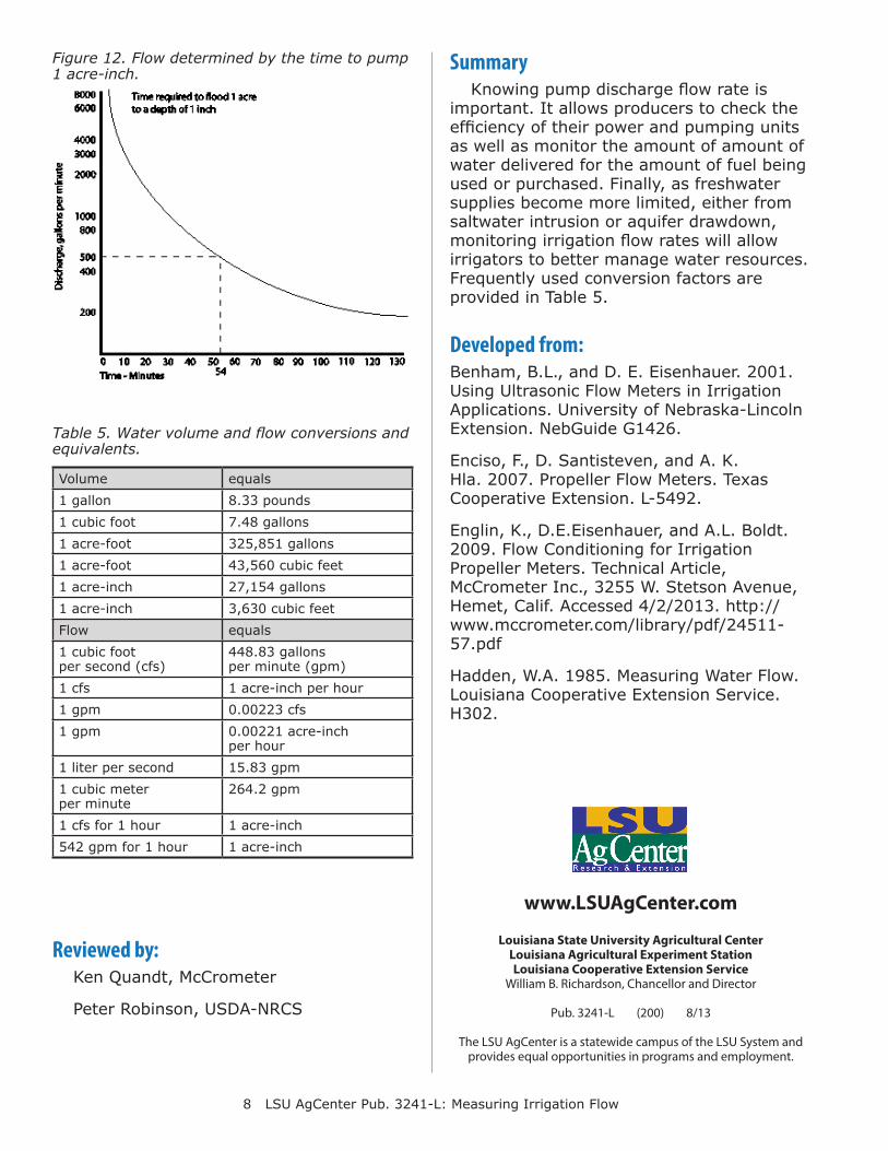
Time to Pump an Acre-inchThe flow from a pump also can be
estimated by recording the time it takes to fill a level field with 1 acre-inch (Figure 12). This method is especially useful for rice and crawfish production where a pool of standing water is desirable. In the figure, a flooding time of 54 minutes to add 1 acre-inch equals a flow of 500 gallons per minute.
8 LSU AgCenter Pub. 3241-L: Measuring Irrigation Flow
Louisiana State University Agricultural CenterLouisiana Agricultural Experiment StationLouisiana Cooperative Extension Service
William B. Richardson, Chancellor and Director
Pub. 3241-L (200) 8/13
The LSU AgCenter is a statewide campus of the LSU System and provides equal opportunities in programs and employment.
www.LSUAgCenter.com
Figure 12. Flow determined by the time to pump 1 acre-inch.
Table 5. Water volume and flow conversions and equivalents.
Volume equals1 gallon 8.33 pounds1 cubic foot 7.48 gallons1 acre-foot 325,851 gallons1 acre-foot 43,560 cubic feet1 acre-inch 27,154 gallons1 acre-inch 3,630 cubic feetFlow equals1 cubic foot per second (cfs)
448.83 gallons per minute (gpm)
1 cfs 1 acre-inch per hour1 gpm 0.00223 cfs1 gpm 0.00221 acre-inch
per hour1 liter per second 15.83 gpm1 cubic meter per minute
264.2 gpm
1 cfs for 1 hour 1 acre-inch542 gpm for 1 hour 1 acre-inch
SummaryKnowing pump discharge flow rate is
important. It allows producers to check the efficiency of their power and pumping units as well as monitor the amount of amount of water delivered for the amount of fuel being used or purchased. Finally, as freshwater supplies become more limited, either from saltwater intrusion or aquifer drawdown, monitoring irrigation flow rates will allow irrigators to better manage water resources. Frequently used conversion factors are provided in Table 5.
Reviewed by:Ken Quandt, McCrometer
Peter Robinson, USDA-NRCS
Developed from:Benham, B.L., and D. E. Eisenhauer. 2001. Using Ultrasonic Flow Meters in Irrigation Applications. University of Nebraska-Lincoln Extension. NebGuide G1426.
Enciso, F., D. Santisteven, and A. K. Hla. 2007. Propeller Flow Meters. Texas Cooperative Extension. L-5492.
Englin, K., D.E.Eisenhauer, and A.L. Boldt. 2009. Flow Conditioning for Irrigation Propeller Meters. Technical Article, McCrometer Inc., 3255 W. Stetson Avenue, Hemet, Calif. Accessed 4/2/2013. http://www.mccrometer.com/library/pdf/24511-57.pdf
Hadden, W.A. 1985. Measuring Water Flow. Louisiana Cooperative Extension Service. H302.