measurementand analysis of electromagnetic fields...
TRANSCRIPT
MEASUREMENT AND ANALYSIS OF ELECTROMAGNETICFIELDS FROM TRAMS, TRAINS AND HYBRID CARSMalka N. Halgamuge*, Chathurika D. Abeyrathne and Priyan MendisCivil and Environmental Engineering, School of Engineering, The University of Melbourne, Parkville, VIC3010, Melbourne, Australia
*Corresponding author: [email protected]
Received January 20 2010, revised April 28 2010, accepted May 2 2010
Electricity is used substantially and sources of electric and magnetic fields are, unavoidably, everywhere. The transportationsystem is a source of these fields, to which a large proportion of the population is exposed. Hence, investigation of the effectsof long-term exposure of the general public to low-frequency electromagnetic fields caused by the transportation system is cri-tically important. In this study, measurements of electric and magnetic fields emitted from Australian trams, trains and hybridcars were investigated. These measurements were carried out under different conditions, locations, and are summarised in thisarticle. A few of the measured electric and magnetic field strengths were significantly lower than those found in prior studies.These results seem to be compatible with the evidence of the laboratory studies on the biological effects that are found in theliterature, although they are far lower than international levels, such as those set up in the International Commission on Non-Ionising Radiation Protection guidelines.
INTRODUCTION
Transportation systems create a number of environ-mental problems through the emission of harmfulgases into the atmosphere. In the twenty-first century,inhabitants of both developing and developedcountries are consuming more energy for productionand transport, thus increasing the level of CO2 emis-sions. Consequently, it is vital to limit energy con-sumption at the same time as developing thetransport industry(1). Electrical and hybrid technol-ogies have been introduced to reduce the emission ofharmful gases. Most trams, trains and hybrid carsare now electrically operated, therefore emitting lessCO2 and less pollution into the environment.Because of the use of electricity in these transpor-tation systems, the issue of electromagnetic fields(EMFs) has arisen. People using trains, trams andhybrid cars are exposed to higher alternating andstatic magnetic field strength than are in the sur-rounding area. This study analyses the weak mag-netic field strength from transportation systems. Thefindings can be used: (1) to reduce the magneticfields from transportation system and (2) to set-upnew laboratory experiments to observe the possiblebiological effects. Those replicated biological studiescan contribute to future recommendations forexposure limits, such as those published by theWorld Health Organization and the InternationalCommission on Non-Ionising Radiation Protection(ICNIRP)(2). The recommendations of the ICNIRPfor an exposure limit value for low-frequency EMFsand microwaves aims to protect people against nervestimulation and body heating, respectively. About
30 y ago, the question arose as to whether weak,low-frequency EMFs constitutes a major healthhazard. This question has still not been answeredsatisfactorily, particularly in the case of long-termexposure. The understanding of the impact of EMFscan be increased by the replicated biological studies.
Recently, magnetic levitation systems have begunto be developed around the globe. Both the Japaneseand the German transportation systems use mag-netic fields: these are called magnetic levitation ormaglev systems. The most sophisticated ‘conventional’electrified system is the French TGV system, wherehigh-speed trains having reached 574.8 km h–1(3). TheJapanese Series 700 Shinkansen and a range ofsophisticated high speed electric railway systemshave been deployed in Europe and, more recently, inother countries, specifically in the northeast USA(4).In ‘conventional’ transportation systems, energy issupplied as fuel and the internal combustion engine(ICE) uses a motor with electrical ignition. In‘advanced’ systems, the motors are electrical (alter-nating current (AC) or direct current (DC)) and thepower supplies can also be electrical (AC or DC).Railway safety signalling systems also use electricity,initially when lanterns are replaced with signallights, and more recently by radio controls(4). High-speed intercity lines became popular and some cities(for example Shanghai) hail these infrastructures asprestigious. DC is used in early applications; later,AC is used, particularly when it is essential to trans-mit electrical energy over extensive distances(5).Hybrid electric vehicles (HEV) produce less carbondioxide emissions and have better fuel economy than
# The Author 2010. Published by Oxford University Press. All rights reserved. For Permissions, please email: [email protected]
Radiation Protection Dosimetry (2010), Vol. 141, No. 3, pp. 255–268 doi:10.1093/rpd/ncq168Advance Access publication 16 June 2010
at University of M
elbourne on Novem
ber 20, 2010rpd.oxfordjournals.org
Dow
nloaded from
conventional cars with an ICE(6). Toyota’s Prius isthe first commercial HEV that is introduced inJapan in 1997, and the batteries are redesigned in2000(7). All these ‘advancements’ contribute to thegrowth in concern about the impact of EMFs fromtransportation systems. During the 1960s and 1970s,when high voltage power lines are more visible,health and safety concerns were enlarged(4). There ismuch speculation that there may be a considerable,and still not sufficiently investigated, impact of exist-ing transportation systems (tram, train and hybridvehicle and high-speed maglev lines) on the environ-ment, specifically on biological tissue that is exposedover a long period. Given the potential effect ofEMFs, organisations that are responsible for mana-ging health issues have taken some practical steps toprovide clear information about these effects.Managing health issues in relation to the transpor-tation systems is presently at an early stage ofdeployment. This clarification significantly changesthe range of frequencies to be considered for ‘trans-portation system EMFs’, producing open-endedquestions about the impact of technology onhumans and/or the environment. The developmentof transportation systems towards higher speeds andgreater efficiency seems largely to ignore the poten-tial risks associated with these changes.
Higher currents and voltages are required by largerand more efficient systems, which subsequently causeslarger magnetic and electric fields. On the other hand,smaller systems put the user or operator closer to thesource of the fields, which can sometimes lead tohigher local exposures. All these factors demonstratethe difficulty in establishing the patterns of potentialexposure that are connected to the transportationsystems. A local example is a consideration of themeasurements of EMFs that are emitted from theAustralian tram, train and hybrid car system. Thisinvestigation involves the following measurements: (1)exposure as a passenger inside and outside of a tram,train and hybrid car; (2) field exposure at head level,seat level and floor level; (3) field exposure whenengines move at a higher speed, when a tram climbs ahill and when a vehicle is stationary and (4) compari-son of exposure levels with existing experimentalresults for the biological effect of magnetic fields inthe literature and with the international limits(ICNIRP), in order to quantify the biological effects.
This paper is organised as follows. In theResearch findings section, the scientific studies ofEMFs from transportation systems are describedthat have been carried out in several countries. Theoperation of trams, trains and hybrid cars areexplained in the section on operation of transpor-taion systems. In the experimental setup and resultssection, the experimental study and results ofmeasured EMF strengths of the Australian transpor-tation system are described. In the discussion, an
analysis of measured field strength from transpor-tation system with ICNIRP limit and the biologicaleffects of the laboratory studies carried out in the lit-erature are given and the conclusion concludes thepaper.
THE RESEARCH FINDINGS
Trams and trains
Scientific investigations of the impact of EMFs fromtransportation systems have been carried out inseveral countries. These studies have focused on bothoccupational and public exposure, such as enginedrivers, transport workers and passengers. Thestudies of EMF exposure levels for several types oftrains, such as DC underground, AC trains andMaglev, are summarised in Table 1. The measure-ments were carried out using various types of mag-netic field measuring instruments that are operatedin various frequency bands. The static and alternat-ing magnetic flux densities in the electric trains andtrams used in the UK were studied(8). The recordingdevice was an EMDEX II logging magnetic fielddosemeter. The measurements were taken for theLondon underground 600 V DC system, the subur-ban railways at 750 V DC, and mainline railways at25 kV and 50 Hz. In the underground system, staticmagnetic flux densities and alternating fields onboth the standard and experimental trains wereobserved. Moreover, in the suburban railways, thealternating magnetic flux densities of a train with avariable frequency AC induction motor wererecorded. In addition, the (quasi) static magneticflux densities in the mainline railways were recorded.The maximum alternating flux density was at 100 Hz,and the typical static magnetic flux densities towhich passengers might be exposed was less than300 mG(8). In another study carried out in the UKelectric transport system, the static magnetic fieldsand time-varying magnetic fields near facilities wereobserved using a root-mean-square (RMS) magnet-ometer(9). Chen and Yianting(10) took measurementsof the EMFs emitted from the Beijing 825 V DCmetro system using a spectral analysis instrument.EMF’s measured from the loop antenna in theTunis, 750 V DC railway systems were found to liewithin the frequency range 100 kHz–20 MHz,which mainly radiated from the power electronicsystems embedded in the train(11).
Measurements taken in the USA were carried outon a platform directly above the contact wire forelectric traction as a train passed. Measurementsperformed inside two types of locomotives in the ACSwiss railway system revealed that, in modernsystems the maximum magnetic fields are less thanthose of older systems. Measurements from Japanesetrains showed magnetic fields in the substation,
M. N. HALGAMUGE ET AL.
256
at University of M
elbourne on Novem
ber 20, 2010rpd.oxfordjournals.org
Dow
nloaded from
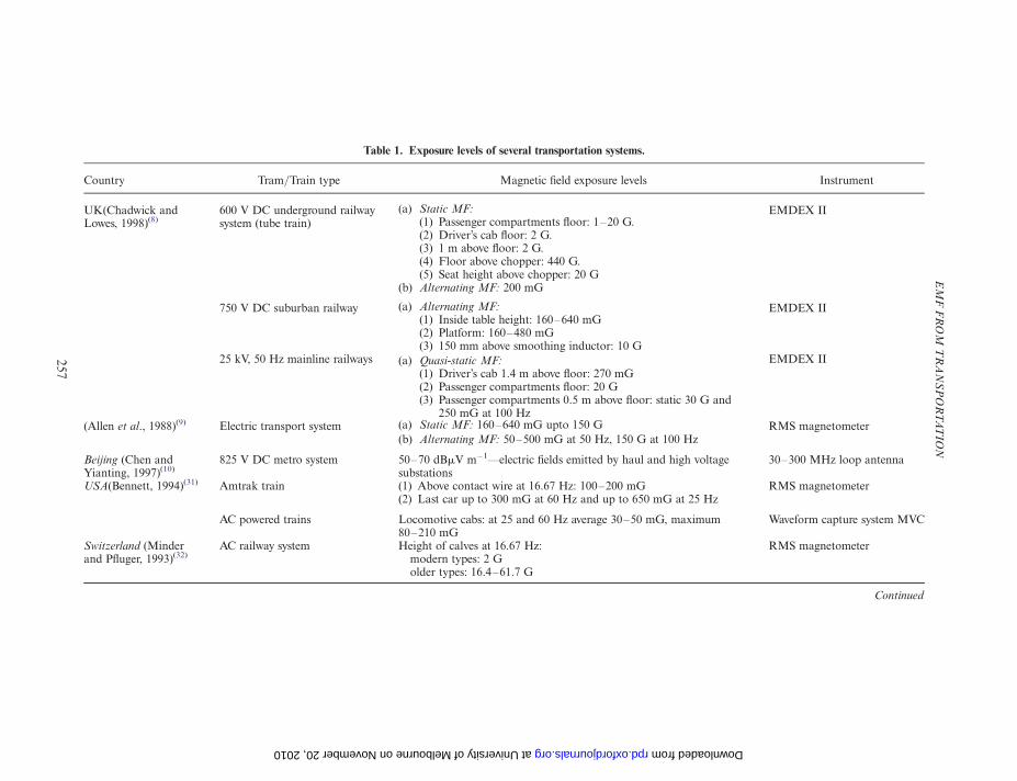
Table 1. Exposure levels of several transportation systems.
Country Tram/Train type Magnetic field exposure levels Instrument
UK(Chadwick andLowes, 1998)(8)
600 V DC underground railwaysystem (tube train)
(a) Static MF:(1) Passenger compartments floor: 1–20 G.(2) Driver’s cab floor: 2 G.(3) 1 m above floor: 2 G.(4) Floor above chopper: 440 G.(5) Seat height above chopper: 20 G
(b) Alternating MF: 200 mG
EMDEX II
750 V DC suburban railway (a) Alternating MF:(1) Inside table height: 160–640 mG(2) Platform: 160–480 mG(3) 150 mm above smoothing inductor: 10 G
EMDEX II
25 kV, 50 Hz mainline railways (a) Quasi-static MF:(1) Driver’s cab 1.4 m above floor: 270 mG(2) Passenger compartments floor: 20 G(3) Passenger compartments 0.5 m above floor: static 30 G and
250 mG at 100 Hz
EMDEX II
(Allen et al., 1988)(9) Electric transport system (a) Static MF: 160–640 mG upto 150 G(b) Alternating MF: 50–500 mG at 50 Hz, 150 G at 100 Hz
RMS magnetometer
Beijing (Chen andYianting, 1997)(10)
825 V DC metro system 50–70 dBmV m– 1—electric fields emitted by haul and high voltagesubstations
30–300 MHz loop antenna
USA(Bennett, 1994)(31) Amtrak train (1) Above contact wire at 16.67 Hz: 100–200 mG(2) Last car up to 300 mG at 60 Hz and up to 650 mG at 25 Hz
RMS magnetometer
AC powered trains Locomotive cabs: at 25 and 60 Hz average 30–50 mG, maximum80–210 mG
Waveform capture system MVC
Switzerland (Minderand Pfluger, 1993)(32)
AC railway system Height of calves at 16.67 Hz: RMS magnetometermodern types: 2 Golder types: 16.4–61.7 G
Continued
EM
FF
RO
MT
RA
NS
PO
RTA
TIO
N
257
at University of Melbourne on November 20, 2010 rpd.oxfordjournals.org Downloaded from
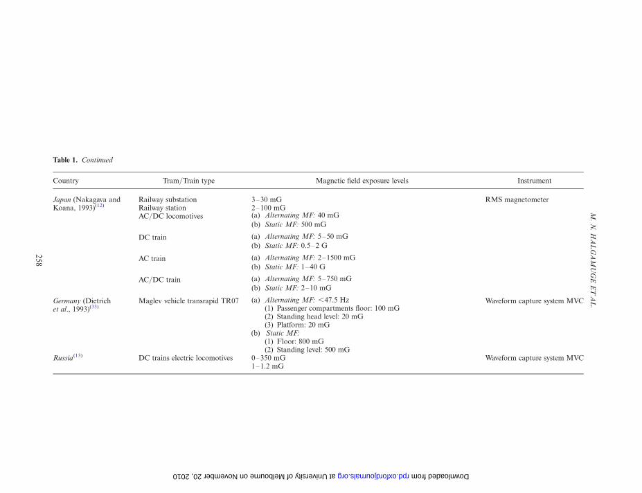
Table 1. Continued
Country Tram/Train type Magnetic field exposure levels Instrument
Japan (Nakagava andKoana, 1993)(12)
Railway substation 3–30 mG RMS magnetometerRailway station 2–100 mGAC/DC locomotives (a) Alternating MF: 40 mG
(b) Static MF: 500 mG
DC train (a) Alternating MF: 5–50 mG(b) Static MF: 0.5–2 G
AC train (a) Alternating MF: 2–1500 mG(b) Static MF: 1–40 G
AC/DC train (a) Alternating MF: 5–750 mG(b) Static MF: 2–10 mG
Germany (Dietrichet al., 1993)(33)
Maglev vehicle transrapid TR07 (a) Alternating MF: ,47.5 Hz(1) Passenger compartments floor: 100 mG(2) Standing head level: 20 mG(3) Platform: 20 mG
(b) Static MF:(1) Floor: 800 mG(2) Standing level: 500 mG
Waveform capture system MVC
Russia(13) DC trains electric locomotives 0–350 mG Waveform capture system MVC1–1.2 mG
M.N
.H
AL
GA
MU
GE
ET
AL
.
258
at University of Melbourne on November 20, 2010 rpd.oxfordjournals.org Downloaded from
railway station, DC train, AC train and AC/DClocomotives(12). A waveform capturing system,Magneto-Variation Complex (MVC), was used forrecording magnetic fields in AC powered US trainsand in the Maglev Vehicle Transrapid TR07 inGermany(13). In Maglev, most of the time-variablemagnetic fields were at frequencies below 47.5 Hzand within the waiting area of the passenger station,time-variable magnetic field levels produced by thepassing train were observed. A portable waveformcapture system MVC was used to measure magneticlevels in Russian DC trains. The most probable DClevels of electric locomotives and the quasi-staticfields in DC trains were found to be higher than thenatural geomagnetic field(13).
Hybrid cars
Several research efforts(14 – 16) have showed that sig-nificant magnetic fields are radiated from steel beltedtyres in hybrid cars. These magnetic fields are gener-ated from the tyres as a result of the reinforcing beltsof magnetised steel wire that are used in their manu-facture. Passengers in a car can be exposed to alter-nating magnetic fields generated by the car(15). Thevehicle’s geometry in relation to the tyres can also bea vital factor in verifying the level of exposure of thepassengers. Vedholm and Hamnerius(15) have carriedout magnetic field analysis while a car is stationary,using a NARDA EFA200 EMF analyser. The fieldstrengths in the 5–2000 Hz range were found to bearound 29 mG at the front left seat, 9 mG at the backleft seat, 9 mG at the front right seat and 19 mG atthe back right seat level. Higher magnetic fields wereproduced on the left side of the car where the leftrear foot level was 140 mG. Another study hasobserved magnetic field strength in the same low fre-quency range of 5–2000 Hz while a car is moving at80 km h– 1, using 12 different cars(14). Average read-ings at the left floor level were found to be 32.2 mGand at the back seat were found to be 32.8 mG. Thisstudy also measured magnetic field strength fromtyres at a distance 2 cm away from the wheel using abalancing machine. Average magnetic field strengthfrom new tyres was 224 mG, and from used tyres was292 mG. Moreover, field strengths from tyres withsteel rims, such as 381 mG, were higher than thosewith aluminium rims.
Recent work(17) has measured the magnetic fieldstrength from Toyota Prius cars in the same fre-quency range. The magnetic field strength was con-sistently higher at the rear seats than at the frontseats. The study also suggested that the low-fre-quency magnetic field strength is larger when boththe gasoline engine and electric motor were running;for example, when the car is accelerating, warmingup, climbing slight hills or charging the battery. Forthe period of hard acceleration, field strength could
go up to 6–8 mG at the rear seat level; when operat-ing with the electric motor alone, field strength wasfound to be 3 mG at the seat level.
OPERATION OF TRANSPORTATIONSYSTEMS
Trams and trains
In an electric railway, the trains and trams are sup-plied via sliding contacts from a supply line—calledthe centenary or overhead line—that is situated overthe railway tracks. The current generally returnsto the substation via the rails, a separate return con-ductor, or via the earth. The large electrical plantsin the network are constituted of sub-plants, whichare electrically independent. Each single sub-plantconsists essentially of overhead lines, buried cablesand rails. Two different substations that are equippedwith static AC–DC conversion groups supply thesub-network.
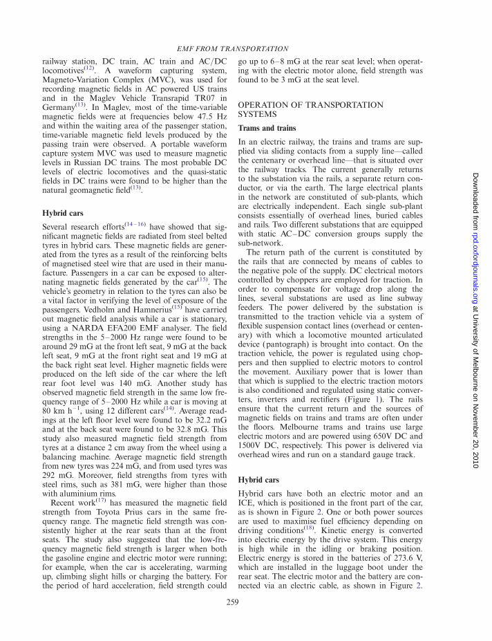
The return path of the current is constituted bythe rails that are connected by means of cables tothe negative pole of the supply. DC electrical motorscontrolled by choppers are employed for traction. Inorder to compensate for voltage drop along thelines, several substations are used as line subwayfeeders. The power delivered by the substation istransmitted to the traction vehicle via a system offlexible suspension contact lines (overhead or centen-ary) with which a locomotive mounted articulateddevice (pantograph) is brought into contact. On thetraction vehicle, the power is regulated using chop-pers and then supplied to electric motors to controlthe movement. Auxiliary power that is lower thanthat which is supplied to the electric traction motorsis also conditioned and regulated using static conver-ters, inverters and rectifiers (Figure 1). The railsensure that the current return and the sources ofmagnetic fields on trains and trams are often underthe floors. Melbourne trams and trains use largeelectric motors and are powered using 650V DC and1500V DC, respectively. This power is delivered viaoverhead wires and run on a standard gauge track.
Hybrid cars
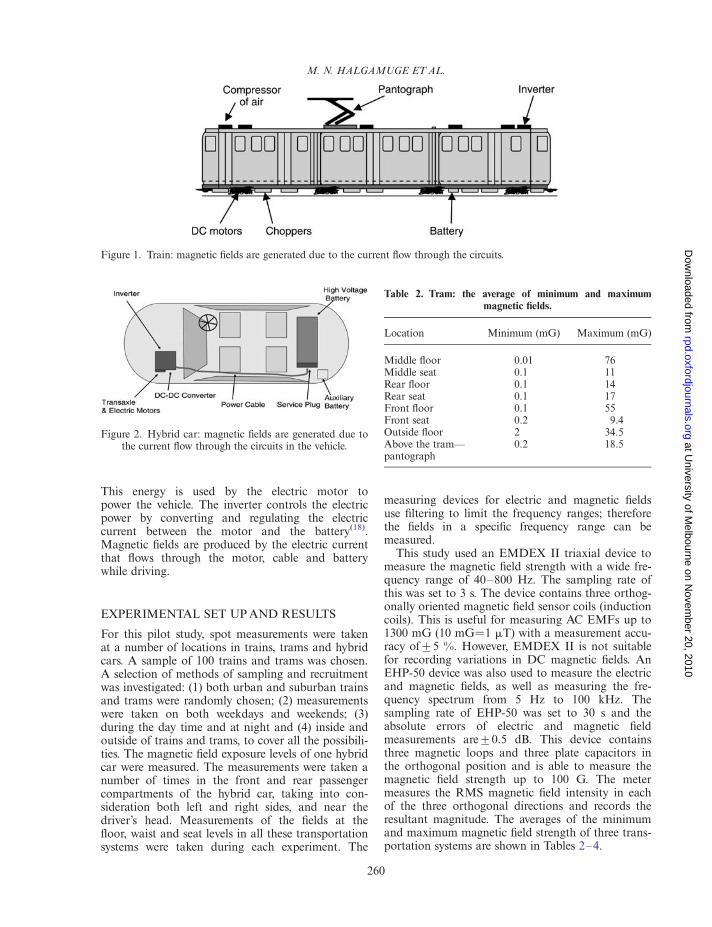
Hybrid cars have both an electric motor and anICE, which is positioned in the front part of the car,as is shown in Figure 2. One or both power sourcesare used to maximise fuel efficiency depending ondriving conditions(18). Kinetic energy is convertedinto electric energy by the drive system. This energyis high while in the idling or braking position.Electric energy is stored in the batteries of 273.6 V,which are installed in the luggage boot under therear seat. The electric motor and the battery are con-nected via an electric cable, as shown in Figure 2.
EMF FROM TRANSPORTATION
259
at University of M
elbourne on Novem
ber 20, 2010rpd.oxfordjournals.org
Dow
nloaded from
This energy is used by the electric motor topower the vehicle. The inverter controls the electricpower by converting and regulating the electriccurrent between the motor and the battery(18).Magnetic fields are produced by the electric currentthat flows through the motor, cable and batterywhile driving.
EXPERIMENTAL SET UP AND RESULTS
For this pilot study, spot measurements were takenat a number of locations in trains, trams and hybridcars. A sample of 100 trains and trams was chosen.A selection of methods of sampling and recruitmentwas investigated: (1) both urban and suburban trainsand trams were randomly chosen; (2) measurementswere taken on both weekdays and weekends; (3)during the day time and at night and (4) inside andoutside of trains and trams, to cover all the possibili-ties. The magnetic field exposure levels of one hybridcar were measured. The measurements were taken anumber of times in the front and rear passengercompartments of the hybrid car, taking into con-sideration both left and right sides, and near thedriver’s head. Measurements of the fields at thefloor, waist and seat levels in all these transportationsystems were taken during each experiment. The
measuring devices for electric and magnetic fieldsuse filtering to limit the frequency ranges; thereforethe fields in a specific frequency range can bemeasured.
This study used an EMDEX II triaxial device tomeasure the magnetic field strength with a wide fre-quency range of 40–800 Hz. The sampling rate ofthis was set to 3 s. The device contains three orthog-onally oriented magnetic field sensor coils (inductioncoils). This is useful for measuring AC EMFs up to1300 mG (10 mG¼1 mT) with a measurement accu-racy of+5 %. However, EMDEX II is not suitablefor recording variations in DC magnetic fields. AnEHP-50 device was also used to measure the electricand magnetic fields, as well as measuring the fre-quency spectrum from 5 Hz to 100 kHz. Thesampling rate of EHP-50 was set to 30 s and theabsolute errors of electric and magnetic fieldmeasurements are+0.5 dB. This device containsthree magnetic loops and three plate capacitors inthe orthogonal position and is able to measure themagnetic field strength up to 100 G. The metermeasures the RMS magnetic field intensity in eachof the three orthogonal directions and records theresultant magnitude. The averages of the minimumand maximum magnetic field strength of three trans-portation systems are shown in Tables 2–4.
Figure 1. Train: magnetic fields are generated due to the current flow through the circuits.
Figure 2. Hybrid car: magnetic fields are generated due tothe current flow through the circuits in the vehicle.
Table 2. Tram: the average of minimum and maximummagnetic fields.
Location Minimum (mG) Maximum (mG)
Middle floor 0.01 76Middle seat 0.1 11Rear floor 0.1 14Rear seat 0.1 17Front floor 0.1 55Front seat 0.2 9.4Outside floor 2 34.5Above the tram—pantograph
0.2 18.5
M. N. HALGAMUGE ET AL.
260
at University of M
elbourne on Novem
ber 20, 2010rpd.oxfordjournals.org
Dow
nloaded from
DISCUSSION
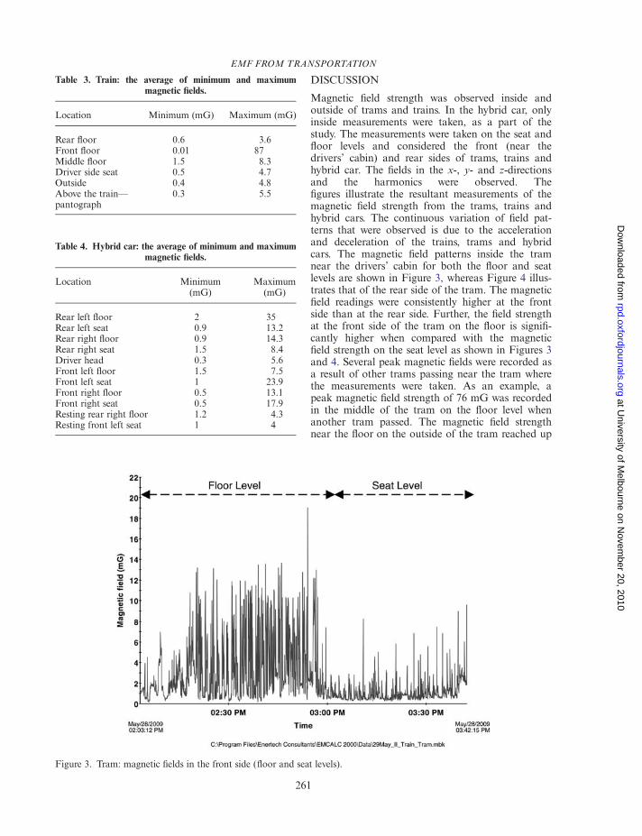
Magnetic field strength was observed inside andoutside of trams and trains. In the hybrid car, onlyinside measurements were taken, as a part of thestudy. The measurements were taken on the seat andfloor levels and considered the front (near thedrivers’ cabin) and rear sides of trams, trains andhybrid car. The fields in the x-, y- and z-directionsand the harmonics were observed. Thefigures illustrate the resultant measurements of themagnetic field strength from the trams, trains andhybrid cars. The continuous variation of field pat-terns that were observed is due to the accelerationand deceleration of the trains, trams and hybridcars. The magnetic field patterns inside the tramnear the drivers’ cabin for both the floor and seatlevels are shown in Figure 3, whereas Figure 4 illus-trates that of the rear side of the tram. The magneticfield readings were consistently higher at the frontside than at the rear side. Further, the field strengthat the front side of the tram on the floor is signifi-cantly higher when compared with the magneticfield strength on the seat level as shown in Figures 3and 4. Several peak magnetic fields were recorded asa result of other trams passing near the tram wherethe measurements were taken. As an example, apeak magnetic field strength of 76 mG was recordedin the middle of the tram on the floor level whenanother tram passed. The magnetic field strengthnear the floor on the outside of the tram reached up
Table 3. Train: the average of minimum and maximummagnetic fields.
Location Minimum (mG) Maximum (mG)
Rear floor 0.6 3.6Front floor 0.01 87Middle floor 1.5 8.3Driver side seat 0.5 4.7Outside 0.4 4.8Above the train—pantograph
0.3 5.5
Figure 3. Tram: magnetic fields in the front side (floor and seat levels).
Table 4. Hybrid car: the average of minimum and maximummagnetic fields.
Location Minimum(mG)
Maximum(mG)
Rear left floor 2 35Rear left seat 0.9 13.2Rear right floor 0.9 14.3Rear right seat 1.5 8.4Driver head 0.3 5.6Front left floor 1.5 7.5Front left seat 1 23.9Front right floor 0.5 13.1Front right seat 0.5 17.9Resting rear right floor 1.2 4.3Resting front left seat 1 4
EMF FROM TRANSPORTATION
261
at University of M
elbourne on Novem
ber 20, 2010rpd.oxfordjournals.org
Dow
nloaded from
to 35 mG when a tram passed on the rail. Most ofthe field strength was in the range of 0.1–55 mG.The magnetic field strength above the centenarytramline varies, with a maximum of 18.5 mG whenthe pantograph of a tram touches it.
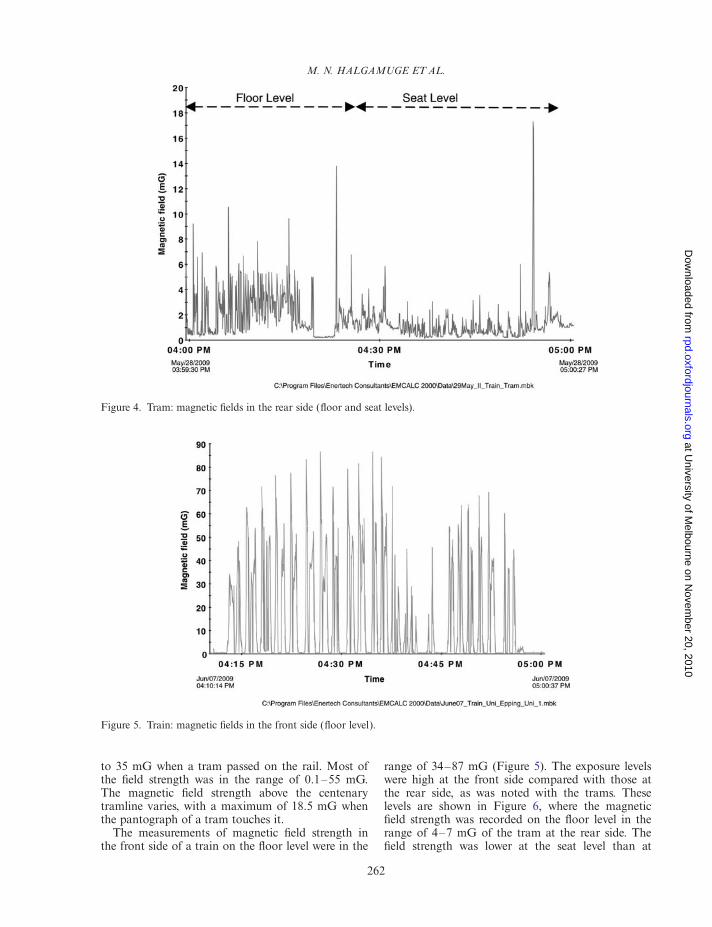
The measurements of magnetic field strength inthe front side of a train on the floor level were in the
range of 34–87 mG (Figure 5). The exposure levelswere high at the front side compared with those atthe rear side, as was noted with the trams. Theselevels are shown in Figure 6, where the magneticfield strength was recorded on the floor level in therange of 4–7 mG of the tram at the rear side. Thefield strength was lower at the seat level than at
Figure 4. Tram: magnetic fields in the rear side (floor and seat levels).
Figure 5. Train: magnetic fields in the front side (floor level).
M. N. HALGAMUGE ET AL.
262
at University of M
elbourne on Novem
ber 20, 2010rpd.oxfordjournals.org
Dow
nloaded from
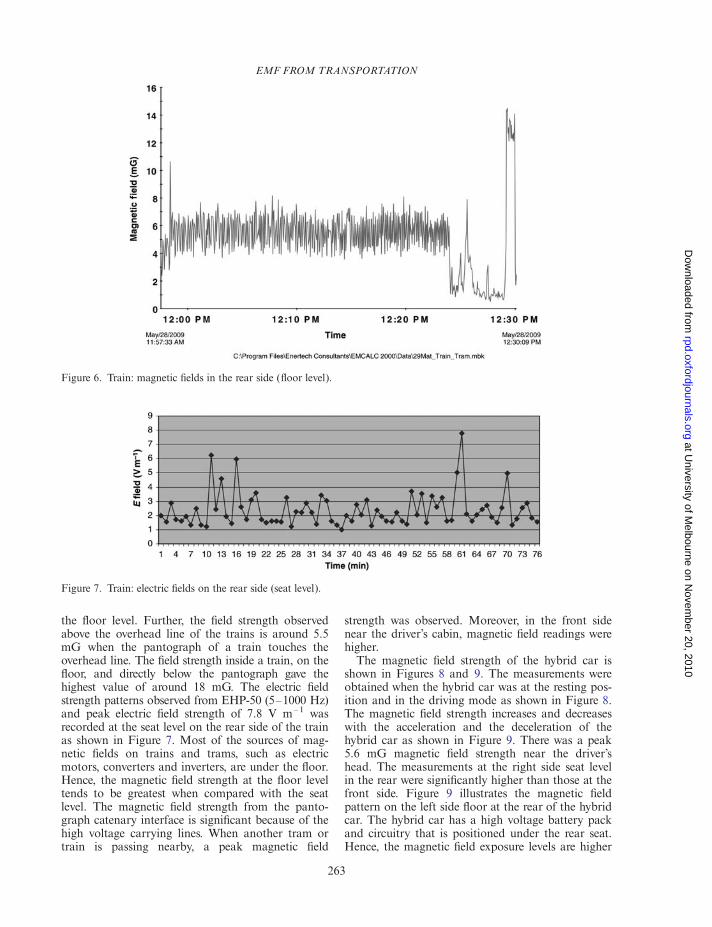
the floor level. Further, the field strength observedabove the overhead line of the trains is around 5.5mG when the pantograph of a train touches theoverhead line. The field strength inside a train, on thefloor, and directly below the pantograph gave thehighest value of around 18 mG. The electric fieldstrength patterns observed from EHP-50 (5–1000 Hz)and peak electric field strength of 7.8 V m– 1 wasrecorded at the seat level on the rear side of the trainas shown in Figure 7. Most of the sources of mag-netic fields on trains and trams, such as electricmotors, converters and inverters, are under the floor.Hence, the magnetic field strength at the floor leveltends to be greatest when compared with the seatlevel. The magnetic field strength from the panto-graph catenary interface is significant because of thehigh voltage carrying lines. When another tram ortrain is passing nearby, a peak magnetic field
strength was observed. Moreover, in the front sidenear the driver’s cabin, magnetic field readings werehigher.
The magnetic field strength of the hybrid car isshown in Figures 8 and 9. The measurements wereobtained when the hybrid car was at the resting pos-ition and in the driving mode as shown in Figure 8.The magnetic field strength increases and decreaseswith the acceleration and the deceleration of thehybrid car as shown in Figure 9. There was a peak5.6 mG magnetic field strength near the driver’shead. The measurements at the right side seat levelin the rear were significantly higher than those at thefront side. Figure 9 illustrates the magnetic fieldpattern on the left side floor at the rear of the hybridcar. The hybrid car has a high voltage battery packand circuitry that is positioned under the rear seat.Hence, the magnetic field exposure levels are higher
Figure 6. Train: magnetic fields in the rear side (floor level).
Figure 7. Train: electric fields on the rear side (seat level).
EMF FROM TRANSPORTATION
263
at University of M
elbourne on Novem
ber 20, 2010rpd.oxfordjournals.org
Dow
nloaded from
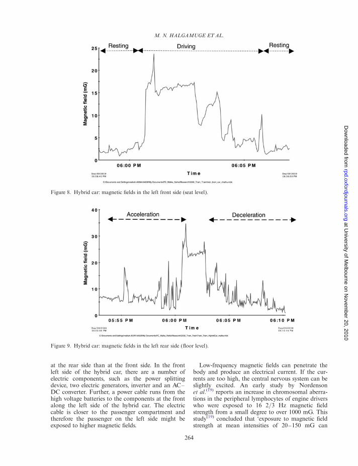
at the rear side than at the front side. In the frontleft side of the hybrid car, there are a number ofelectric components, such as the power splittingdevice, two electric generators, inverter and an AC–DC converter. Further, a power cable runs from thehigh voltage batteries to the components at the frontalong the left side of the hybrid car. The electriccable is closer to the passenger compartment andtherefore the passenger on the left side might beexposed to higher magnetic fields.
Low-frequency magnetic fields can penetrate thebody and produce an electrical current. If the cur-rents are too high, the central nervous system can beslightly excited. An early study by Nordensonet al.(19) reports an increase in chromosomal aberra-tions in the peripheral lymphocytes of engine driverswho were exposed to 16 2/3 Hz magnetic fieldstrength from a small degree to over 1000 mG. Thisstudy(19) concluded that ‘exposure to magnetic fieldstrength at mean intensities of 20–150 mG can
Figure 8. Hybrid car: magnetic fields in the left front side (seat level).
Figure 9. Hybrid car: magnetic fields in the left rear side (floor level).
M. N. HALGAMUGE ET AL.
264
at University of M
elbourne on Novem
ber 20, 2010rpd.oxfordjournals.org
Dow
nloaded from
induce chromosomal damage’. The hydrogennuclear polarisation model(20) predicts a biologicalresponse for oscillating magnetic field strengthsabove 10 mG. The presence of a static magnetic fieldis required for the resonance behaviour and biologi-cal effects can be expected for all frequencies belowa few hundred hertz. In 2001, Belova and Lednevfound that the gravitropic bending of flax seedlingdeviated anomalously from the expected values atvery low amplitudes (0.75,B,50 mG) of the time-varying magnetic field(21). Lednev explained theresults by assuming that the hydrogen nuclei in watermolecules are polarised by the combination of co-parallel static and dynamic magnetic fields(20). Thebiological effect is expected to be dependent on theamplitude of the time-varying magnetic field for agiven frequency. In this model, no resonance fre-quencies occur; however, amplitude windows dooccur. Consequently, in principle, all frequencies thatoccur in the environment up to several hundredhertz can give rise to biological effects. The presenceof the earth’s magnetic field in parallel to the time-varying magnetic field still needs to be included, butthe strength of this static magnetic field is not criti-cal for the predicted biological effect.
Most studies did not intend to clarify how theseweak fields can interact with biological molecules;rather, environmental frequencies and unrealisticallyhigh amplitudes were used to determine the effect ofexposure. A crucial problem that any interactionmodel must deal with is how a large enough signal-to-noise ratio can be obtained to enable the livingcell to detect the signal. For strong signals, the bio-logical effects are well understood due to theirthermal effect. For example, strong microwave
radiation heats body tissue, mainly by setting waterdipoles into rotation; and strong low-frequency elec-tric or magnetic fields will induce electric currents inthe body that can lead to nerve excitation. On theother hand, for extremely weak electromagneticsignals there is no generally accepted theory that canexplain all the biological effects reported in the lit-erature(20,22); Halgamuge et al.(23 – 25).
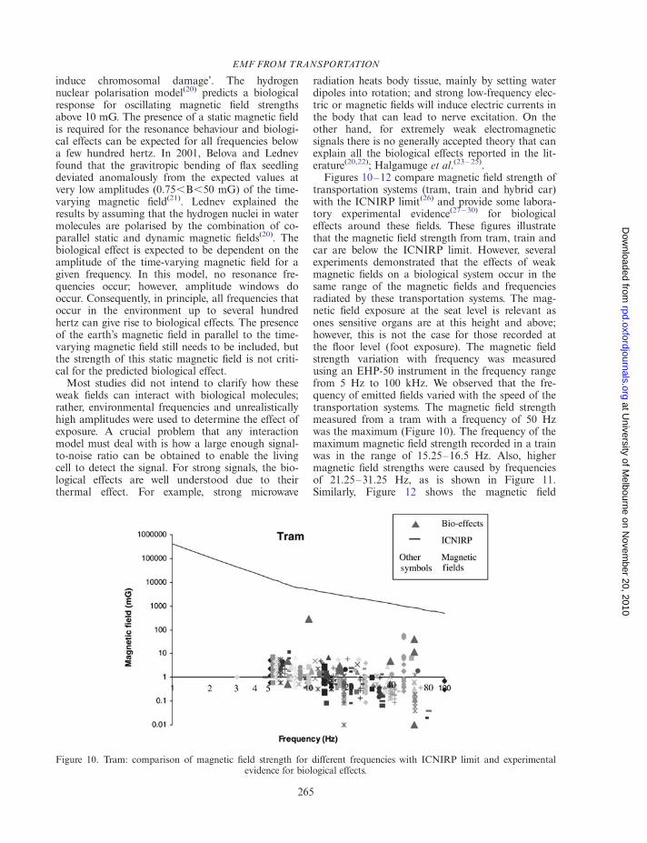
Figures 10–12 compare magnetic field strength oftransportation systems (tram, train and hybrid car)with the ICNIRP limit(26) and provide some labora-tory experimental evidence(27 – 30) for biologicaleffects around these fields. These figures illustratethat the magnetic field strength from tram, train andcar are below the ICNIRP limit. However, severalexperiments demonstrated that the effects of weakmagnetic fields on a biological system occur in thesame range of the magnetic fields and frequenciesradiated by these transportation systems. The mag-netic field exposure at the seat level is relevant asones sensitive organs are at this height and above;however, this is not the case for those recorded atthe floor level (foot exposure). The magnetic fieldstrength variation with frequency was measuredusing an EHP-50 instrument in the frequency rangefrom 5 Hz to 100 kHz. We observed that the fre-quency of emitted fields varied with the speed of thetransportation systems. The magnetic field strengthmeasured from a tram with a frequency of 50 Hzwas the maximum (Figure 10). The frequency of themaximum magnetic field strength recorded in a trainwas in the range of 15.25–16.5 Hz. Also, highermagnetic field strengths were caused by frequenciesof 21.25–31.25 Hz, as is shown in Figure 11.Similarly, Figure 12 shows the magnetic field
Figure 10. Tram: comparison of magnetic field strength for different frequencies with ICNIRP limit and experimentalevidence for biological effects.
EMF FROM TRANSPORTATION
265
at University of M
elbourne on Novem
ber 20, 2010rpd.oxfordjournals.org
Dow
nloaded from
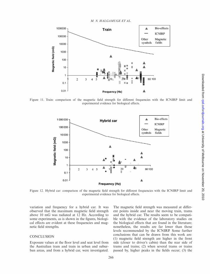
variation and frequency for a hybrid car. It wasobserved that the maximum magnetic field strengthabove 10 mG was radiated at 12 Hz. According tosome experiments, as is shown in the figures, biologi-cal effects are evident at these frequencies and mag-netic field strengths.
CONCLUSION
Exposure values at the floor level and seat level fromthe Australian tram and train in urban and subur-ban areas, and from a hybrid car, were investigated.
The magnetic field strength was measured at differ-ent points inside and near the moving train, tramsand the hybrid car. The results seem to be compati-ble with the evidence of the laboratory studies onthe biological effects that are found in the literature;nonetheless, the results are far lower than thoselevels recommended by the ICNIRP. Some furtherconclusions that can be drawn from this work are:(1) magnetic field strength are higher in the frontside (closer to driver’s cabin) than the rear side oftrams and trains; (2) when several trams or trainspassed by, higher peaks in the fields occur; (3) the
Figure 11. Train: comparison of the magnetic field strength for different frequencies with the ICNIRP limit andexperimental evidence for biological effects.
Figure 12. Hybrid car: comparison of the magnetic field strength for different frequencies with the ICNIRP limit andexperimental evidence for biological effects.
M. N. HALGAMUGE ET AL.
266
at University of M
elbourne on Novem
ber 20, 2010rpd.oxfordjournals.org
Dow
nloaded from
frequency and magnetic field strengths vary withspeed and these are higher during acceleration; (4)magnetic field strength are higher at the rear sidethan at the front side of the hybrid car; (5) magneticfield strength are higher at the left side than at theright side of the hybrid car and (6) the maximumlevels of recorded magnetic field strength are emittedat 50 Hz in the tram; 15.25–16.50 Hz in the trainand 12 Hz in the hybrid car.
ACKNOWLEDGMENTS
The authors would like to express their sincerethanks to the Australian Radiation Protection andNuclear Safety Agency (ARPANSA) for providingall the instruments used in this project. The firstauthor would like to thank Professor JacobEberhardt from Lund University, Sweden, for valu-able discussion about this work.
FUNDING
This work was supported by the Vice-Chancellor’sKnowledge Transfer Grant from The University ofMelbourne, Australia.
REFERENCES
1. Watanabe, T. Some aspects of rolling stock technologiesin the future. QR. RTRI. 44(1), 4–7 (2003).
2. ICNIRP. Guidelines for limiting exposure to time-varying electric, magnetic, and electromagnetic fields(up to 300 GHz). Health Phys. 74, 494–521 (1998).
3. Anthoine, J., Gouriet, J. B. and Rambaud, P. Reductionof the sonic boom from a high-speed train entering agallery, AIAA-2007-3559, 13th AIAA/CEASAeroacoustics Conference, Rome, Italy (2007).
4. Muc, A. Electromagnetic fields associated with trans-portation systems. Toronto: Radiation Health andSafety Consulting, pp. 52 (2001a).
5. Muc, A. Transportation system EMFs. Toronto:Radiation Health and Safety Consulting, pp. 52(2001b).
6. Lave, L. B. and MacLean, H. L. An environmental-economic evaluation of hybrid electric vehicles: Toyota’sPrius vs. its conventional internal combustion enginecorolla. Transport. Res. Part D. 7, 155–162 (2002).
7. Hann, P., Mueller, M. G. and Peters, A. Does thehybrid Toyota Prius lead to rebound effects? Analysis ofsize and number of cars previously owned by Swiss Priusbuyers. Ecol. Econ.. 58, 592–605 (2006).
8. Chadwick, P. and Lowes, F. Magnetic fields on Britishtrains. Ann. Occup. Hyg. 42(5), 331–335 (1998).
9. Allen, S. G., et al. Review of occupational exposure tooptical radiation and electric and magnetic fields withregard to the proposed CEC physical agents directive(Chilton, Didcot, Oxon: National RadiologicalProtection Board) p. 31 (1988).
10. Chen, Z. and Yianting, Z. Measurement and analysisof electromagnetic radiation of city rapid guided transitsystems. Paper presented at the IEEE International
Symposium on Electromagnetic Compatibility (IEEE)pp. 190–193 (1997).
11. Slama, J. B. H. and Chariag, D. Measurement andanalysis of magnetic field radiated from D.C. tramway:a case study for Tunis’s metro. J. Electr. Syst. 4(2),1–12 (2008).
12. Nakagava, M. and Koana, T. Electricity and magnet-ism in biology and medicine. In: Blank,, M., Ed.(San Francisco: Press Inc) pp. 264 (1993).
13. Stavroulakis, P. Biological Effects of ElectromagneticFields (Springer) (2003).
14. Stankowski, S., Kessi, A., Becheiraz, O., Meier-Engel,K. and Meier, M. Low frequency magnetic fieldsinduced by car tire magnetization. Health Phys. 90(2),148–153 (2006).
15. Vedholm, K. and Hamnerius, Y. Personal ExposureResulting from Low Level Low FrequencyElectromagnetic Fields in Automobiles (Goteborg,Sweden: Department of Electromagnetics, ChalmersUniversity of Technology) (1996).
16. Milham, S., Hatfield, J. B. and Tell, R. Magnetic fieldsfrom steel-belted radial tires: implications for epidemio-logic studies. Bioelectromagnetics. 20, 440–445 (1999).
17. Electromagnetic Health Organization. EMF test of2007 Toyota Prius hybrid. Electromagn. Health. (2008).
18. Automobile. Automobile research. Res. Bull. 8 (2000).Available at http://www.tech-cor.net/AutoResBulletin/2000-8/2000-8.html.
19. Nordenson, K., Hansson-Mild, H., Jarventaus, A.,Hirvonen, M., Sandstrom, J., Wilen, N. and Blix, H. N.Chromosomal aberrations in peripheral lymphocytes oftrain engine drivers. Bioelectromagnetics 21, 1–10 (2001).
20. Belova, N. A., Ermakova, O. N., Ermakov, A. M.,Rojdestvenskaya, Z. Y. and Lednev, V. V. The bioeffectsof extremely weak powerfrequency alternating magneticfields. Environmentalist 27(4), 411–416 (2007).
21. Belova, N. A. and Lednev, V. V. Extremely weak alter-nating magnetic fields affect the gravitropic response inplants. Biofizika 46(1), 122–125 (2001).
22. Adair, R. K. Criticism of Lednev’s mechanism for theinfluence of weak magnetic-fields on biological-systems.Bioelectromagnetics 13(3), 231–235 (1992).
23. Halgamuge, M. N., Abeyrathne, C. D. and Mendis, P.Effect of cyclotron resonance frequencies in particles dueto AC and DC electromagnetic fields. World Acad. Sci.40, 416–419 (2009).
24. Halgamuge, M. N., Abeyrathne, C. D. and Mendis, P.Influence of combined AC–DC electromagnetic fields oncell plasma membrane. Paper presented at theBioelectromagnetics (Davos, Switzerland) (2009).
25. Halgamuge, M. N., Persson, B. R. R., Salford, L. G.,Mendis, P. and Eberhardt, J. L. Comparison betweentwo models for interactions between electric and mag-netic fields and proteins in cell membranes. Environ.Eng. Sci. 26(10), 1473–1480 (2009).
26. NRPB. Advice on limiting exposure to electromagneticfields (0–300 GHz). DocNRPB 15(2) 55 (2004).
27. Prato, F. S., Desjardins-Holmes, D., Keenliside, L. D.,McKay, J. C., Robertson, J. A. and Thomas, A. W.Light alters nociceptive effects of magnetic field shield-ing in mice: intensity and wavelength considerations.J. R. Soc. 6, 17–28 (2009).
28. Persinger, M. A. Differential numbers of foci of lympho-cytes within the brains of Lewis rats exposed to weak
EMF FROM TRANSPORTATION
267
at University of M
elbourne on Novem
ber 20, 2010rpd.oxfordjournals.org
Dow
nloaded from
complex nocturnal magnetic fields during development ofexperimental allergic encephalomyelitis. Int. J. Neurosci.119, 166–184 (2009).
29. Novikov, V. V., Novikov, G. V. and Fesenko, E. E.Effect of weak combined static and extremely low-fre-quency alternating magnetic fields on tumor growth inmice inoculated with the Ehrlich ascites carcinoma.Bioelectromagnetics 30(5), 343–351 (2009).
30. Trebbi, G., Borghini, F., Lazzarato, L., Torrigiani, P.,Calzoni, G.L. and Betti, L. Extremely low-frequencyweak magnetic fields enhance resistance of NN tobaccoplants to tobacco mosaic virus and elicit stress-related
biochemical activities. Bioelectromagnetics 28(3),214–223 (2007).
31. Bennett, W. Cancer and power lines. Phys. Today 47,23–29 (1994).
32. Minder, C. M. and Pfluger, D. H. Extremely low fre-quency electromagnetic field measurements (ELF-EMFin Swiss railway engines. Radiat. Prot. Dosim. 48(4),351–354 (1993).
33. Dietrich, F. M., Steiner, G. A., Robserston, D. C. and Feero,W. E. Electricity and magnetism in biology and medicine.In: Bank,, M., Ed. (San Francisco: Press Inc) p. 267(1993).
M. N. HALGAMUGE ET AL.
268
at University of M
elbourne on Novem
ber 20, 2010rpd.oxfordjournals.org
Dow
nloaded from