measurement of the gyromagnetic ratio of a proton in a weak magnetic field
TRANSCRIPT
E LEC TRICAL MEASURE MENTS
MEASUREMENT OF THE GYROMAGNETIC RATIO OF A PROTON IN A
WEAK MAGNETIC FIELD
B. M. Y a n o v s k i i , N. V. S t u d e n t s e v and T . N. T t k h o m i r o v a
Paramagnetic nuclear resonance is at present widely used for measuring magnetizing force. From relation
o~ = r H , (I)
where w is the precession of the paramagnetic nuclei in the magnetic field H, and ~, is a constant called the gyro- magnetic nuclear ratio, the value of the magnetizing force is determined by measuring the frequency when the gyromagnetic nuclear ratio is known. Hence for practical magnetic measurements the value of ~ must be known, and it can only be determined experimentally. Relation (1) shows that ~' can be found if w is measured in a known magnetic field.
In the VNIIM* magnetic measurements laboratory work is being conducted at the present time for deter- mining the value of the gyromagnetic ratio of a proton by meam of the free nuclear induction method. Helmholtz rings serve as a source of the magnetic field whose intensity can be determined by the current flowing through the rings and their geometrical dimensions from the relationship
where K is the constant of the rings and, I the Current flowing through their windings. The Helmholtz rings used in these tests consist of quartz cylinders some 30 cm in diameter wound with bare wire. An accurate value of the parameters of one of the five rings is given in the table attached.
Distance between the mean planes of the windings, mm
135~ • 0,002
Mean diameter of the wire, mm
0.9470+0.0003
External diamemr of the windings, mm
I belt II belt I generatrix II generatrix I generatrix II generatrix
2704658 + 0,002 270.660 + 0 ,002 270o712-I-0,002 270j702 :I: 0,002
The value of the constant of this coil referred to its center is K = (0.666300 i 0.000020) Oe/amp.
The current in the windings is measured by a balancing method with an error of the order of 1" 10"s%. This accuracy was attained by means of enclosing the standard elelmnt and resistance in a thermostatically controlled chamber.
A glass cube of a volume of 8 cm s filled with distilled water is used as a transducer for measuring the magnetizing force. The irregularities of the Helmholtz ring magnetic field in such a volume do not exceed 2" lO'S%.
* Publ. note: VNIIM = All-Union Scientific Research Institute of Metrology.
126
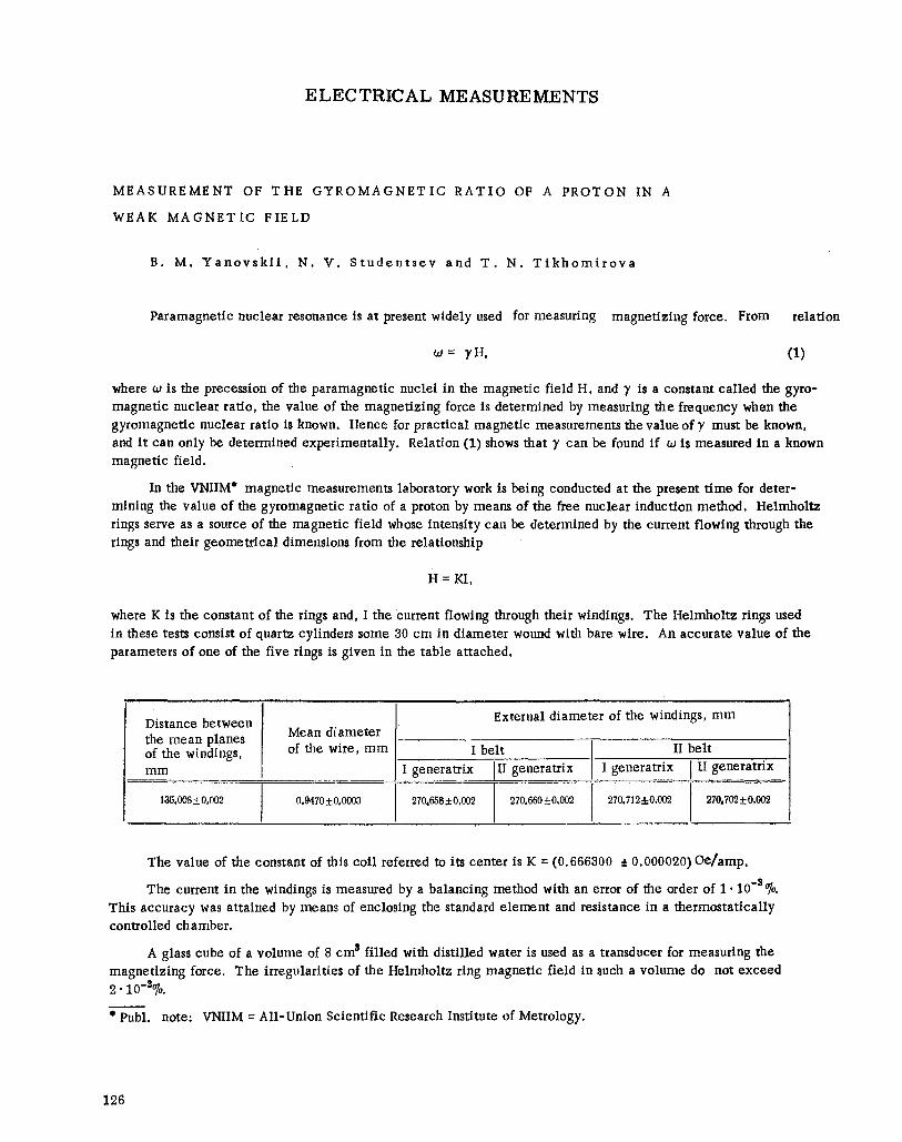
The value of frequency w is measured by beating the nuclear frequency against a standard frequency. block schematic of the circuit for measuring this frequency is shown in the figure attached.
F Signal
Frequency measuring circuit. R is the receiver, LO is the loop oscillograph, M is the mixer, SF are standard frequencies, and A is the amplifier.
The
In order to be able to measure accurately the difference frequency it is necessary to have the standard frequency clnse to the precession frequency of the nuclear spins. This frequency is obtained by means of dividing the crystal oscillator frequency which is periodically checked against a standard frequency received by the radio receiver R. The error of these standard frequencies does not exceed 10"4% . The measured and standard frequencies are fed to the mixer, M. The difference frequency is recorded on a film of a loop oscillograph which also records time signal pips every 0.01 sec.
Since the measurements are made in the magnetic field of the earth the frequency of the nuclear precession corresponds to the value of the vector sum of the magnetic field intensity of the coil and the earth. Hence in order to exclude the earth's
magnetic field, intensity measurements are made with the current in the coil flowing in two opposite directions. In this instance the gyromagnetic ratio can be expressed by the formula:
' = - ~ - - V 2
where f r and f9 are the frequencies corresponding to the two current directions in the coil, f3 is the frequency of the nuclear signal in the magnetic fietd of the earth, Epi isthe sum of the correcting terms.
Measurements were made in a surburban laboratory at Kavgolovo where is was possible to record the varia- tions in the earth's magnetic field components which form part of the correcting terms in (2).
The laboratory plans to measure the gyromagnetic ratio of the proton with the magnetic field of the earth
balanced out. The measuring technique will then be comiderably simplified.
The first determination of the gyromagnetic ratio of the proton made with the Helmholtz rings whose para-
meters are given in the table produced the following value
), = (2.67520 i 0.00015). 104 sec ' i . Oe "I.
Above error has in the main a random nature and is due to the error of reading the loop oscillograph film
and of the variable instruments.
The value of the gyromagnetic ratio of the proton was determined by the method of forced nuclear resonance by Thomas and others (USA) in a field of an electromagnet of some 5,000 Oe and by Wilhelmy (Germany) in a
field of a solenoid of some 100 Oe. The following data was obtained:
(2.67523 i 0.00006). 104 Oe -1. sec "1 [1] (2.67549 i 0.00008). 104 Oe "1. sec "1 [2]. All the values of )' are given without a diamagnetic correction.
In comparing the value of y obtained by us by the method of free nuclear induction in a field of 0 . 6 0 e with the values obtained in [1] and [21 we find that it differs from them by an amount of the order of the dif-
ference between the two latter results.
The measurement of the gyromagnetic ratio of the proton by the method of free nuclear induction has the advantage over the method of forced resonance in providing the possibility of calculating the field intensity H from the geometrical dimensions of the coil which can be determined fairly accurately. Whereas in the method of forced resonance [1] the magnetic field inten-~ity is determined experimentally by measuring interaction force between the magnetic field and the field of a current carrying coil. Hence in the latter method there are many
127
more sources of systematic errors. The measuring method of [2] hasthe drawbackof using 10 amp in order to produce the required field, and an accurate measurement of such a current is difficult.
The Khar 'kov State Institute of Measures and Measuring Instruments is determining the gyromagnetic ratio by a method similar to [1]. The results of the work of the KhGIMIP and the VNIIM which are using different methods may not only be of interest for determining the numerical value of ?' but also for evaluating the accuracy of reproducing the absolute ampere. In method [1] the value of the current measured in the experiment is used in the numerator of the formula for calculating ),, and in the method of free nuclear induction in the denominator. Thus the systematic error in reproducing the absolute ampere will in the first case tend to increase the value of )" and in the second ease to decrease it, if the error in measuring the remaining parameters is smaller than the systematic error in measuring current.
L I T E R A T U R E C I T E D
[1] Thomas, Driscoll and Hipple, Phys. Rev. 78, 787, 1950.
[2] W. Wilhelmy, Ann. Phys. 6 Folge, Bd. 19, 329, 1957.
H I G H V O L T A G E T E S T G E A R
Y u . Y a . D o n d e
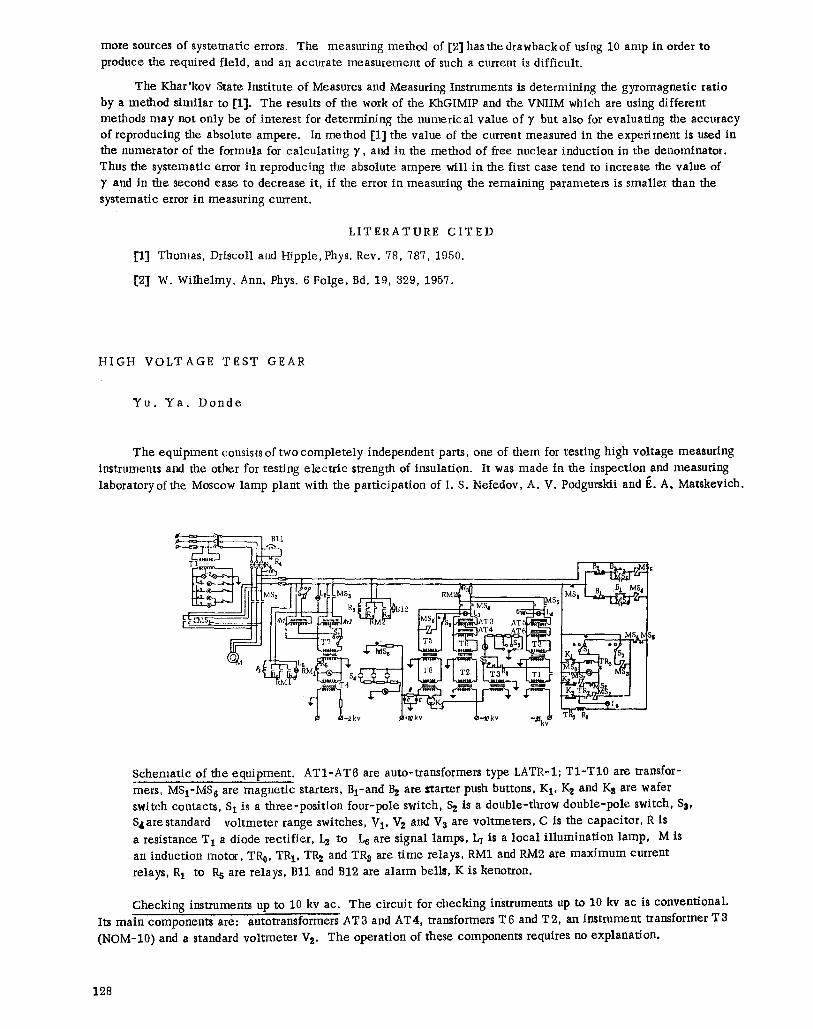
The equipment consists of two complete ly independent parts, one of them for testing high voltage measuring instruments and the other for testing electr ic strength of insulation. It was made in the inspection and measuring laboratory of the Moscow lamp plant with the participation of I. S. Nefedov, A. V. Podgurskii and E. A. Matskevich.
BI1
RM1 S4 T3
Schematic of the equipment. AT1-AT6 are auto-transformers type LATR-1; T1-T10 are transfor- mers, MSI-MS a are magnet ic starters, Bl-and B 2 are ttarter push buttons, K 1, K s and K 3 are wafer switch contacts, S 1 is a three-position four-pole switch, Sz is a double-throw double-pole switch, S 3, S4arestandard voltmeter range switches, V1, V2 and Vs are voltmeters, C is the capacitor, R is a resistance T 1 a diode rectifier, Ie to L6 are signal lamps, br is a local i l lumination lamp, M is an induction motor, TR 0' TR I, TR s and TR z are t ime relays, RM1 and RM2 are maximum current relays, R 1 to R 5 are relays, Bl l and B12 are alarm bells, K is kenotron.
Checking instruments up to 10 kv ac. The circuit for checking instruments up to 10 kv ac is conventional. Its main components are: autotransformers AT8 and AT4, transformers T6 and T2, an imtrument transformer T8 (NOM-10) and a standard voltmeter V s. The operation of these components requires no explanation.
128